ALUMINUM CA NTILEVER GATE INSTALLATION … CANTILEVER GATE INSTALLATION ... per industry standard...
36
ALUMINUM INSTALLAT M CANTILEVER TION INSTRUCT GATE TIONS
Transcript of ALUMINUM CA NTILEVER GATE INSTALLATION … CANTILEVER GATE INSTALLATION ... per industry standard...
ALUMINUM CA
INSTALLATION INSTRUCTIONS
ALUMINUM CANTILEVER GATE
INSTALLATION INSTRUCTIONS
NTILEVER GATE
INSTALLATION INSTRUCTIONS


927 Alloy Drive, Thunder Bay, ON P7B 5Z8 www.cmssi.com Phone: 807.623.3352 Fax: 807.623.8257 Toll Free: 1.800.371.0735
P a g e | - 3 -
ARMA Gate Installation Instructions
ALUMINUM CANTILEVER GATE INSTALLATION INSTRUCTIONS
Content:
Step 1: Introduction and Tools ………………………………………………………………......................................................... 4 Step 2: Post Placement …………………………………………………………………………………………………………………………………. 5 Step 3: Bearing Truck and Bracket Installation ……………………………………………………………………………………………… 6 Step 4: Gate Frame Segment Splice and Installation …………………………………………………………………………………..... 11 Step 5: Top and Bottom End Cap Installation ..……………………………………………………………………………………………… 18 Step 6: ARMA Gate Leveling………………………………………………………………………………………………………………………….. 22 Step 7: Roller Guide Assembly Installation ……………………………………………………………………………………………………. 23 Step 8: Gate Assembly Tensioning ………………………………………………………………………………………………………………… 27 Step 9: Closure Guide Assembly Installation …………………………………………………………………………………………………. 29 Step 10: Optional Barbed Wire Kit Installation ……………………………………………………………………………………………… 33 Step 11: Gap Filler Installation ……………………………………………………………………………………………………………………… 35 Step 12: Function Test ………………………………………………………………………………………………………………………………….. 35

927 Alloy Drive, Thunder Bay, ON P7B 5Z8 www.cmssi.com Phone: 807.623.3352 Fax: 807.623.8257 Toll Free: 1.800.371.0735
P a g e | - 4 -
ARMA Gate Installation Instructions
1. Introduction and Tools A basic tool list has been provided as a starting point for the gate installation. Where necessary, specific tools needed are listed and in other cases only wrench opening sizes are provided. This allows the installer to use whatever tools he has available or for personal preference.
1.1. 5/32” Allen Wrench 1.2. 7/32” Allen Wrench 1.3. 3/8” Pin Punch 1.4. 3/8” Metal Drill Bit 1.5. 7/16” Wrench 1.6. 1/2” Wrench 1.7. 9/16” Wrench 1.8. 3/4” Wrench 1.9. 15/16” Wrench opening two required 1.10. Mallet 1.11. Level 1.12. Jack

927 Alloy Drive, Thunder Bay, ON P7B 5Z8 www.cmssi.com Phone: 807.623.3352 Fax: 807.623.8257 Toll Free: 1.800.371.0735
P a g e | - 5 -
ARMA Gate Installation Instructions
2. Post Placement
(Figure 1-A)
Steps:
2.1. Consult customer specification for post size, depth below grade and method of installation below grade. (See figure 1-A)
2.2. “A” =Clear Opening between Gate Latch Post 1 and Main Gate Post per customer specification. The measurement is from inside to inside of post. (See figure 1-A)
2.3. Spacing between Main Gate Post and Counter Balance Post is determined by the following formula B (Post Spacing)=(A/2 )- 11.0” with post installed on center. (See figure 1-A)
2.4. Gate Latch Post 1 and 2 are placed 12.0” apart, measured from inside to inside of post and 90 degrees from long axis. (See figure 1-A)

927 Alloy Drive, Thunder Bay, ON P7B 5Z8 www.cmssi.com Phone: 807.623.3352 Fax: 807.623.8257 Toll Free: 1.800.371.0735
P a g e | - 6 -
ARMA Gate Installation Instructions
3. Bearing Truck and Bracket Installation
(Figure 1-B)
Steps:
3.1. To determine installation height of Bearing Truck Brackets, first refer to customer specification for gate clearance gap. (See figure 1-B)
3.2. Determine Bearing Truck Bracket installation height by measuring the height of the Gate Frame Segment, adding customer specified gate clearance gap and subtracting 3 1/2” for Truck and Top Rail. (See figure 1- B)
927 Alloy Drive, Thunder Bay, ON P7B 5Z8 www.cmssi.com Phone: 807.623.3352 Fax: 807.623.8257 Toll Free: 1.800.371.0735
P a g e | - 7 -
ARMA Gate Installation Instructions
(Figure 1-C)
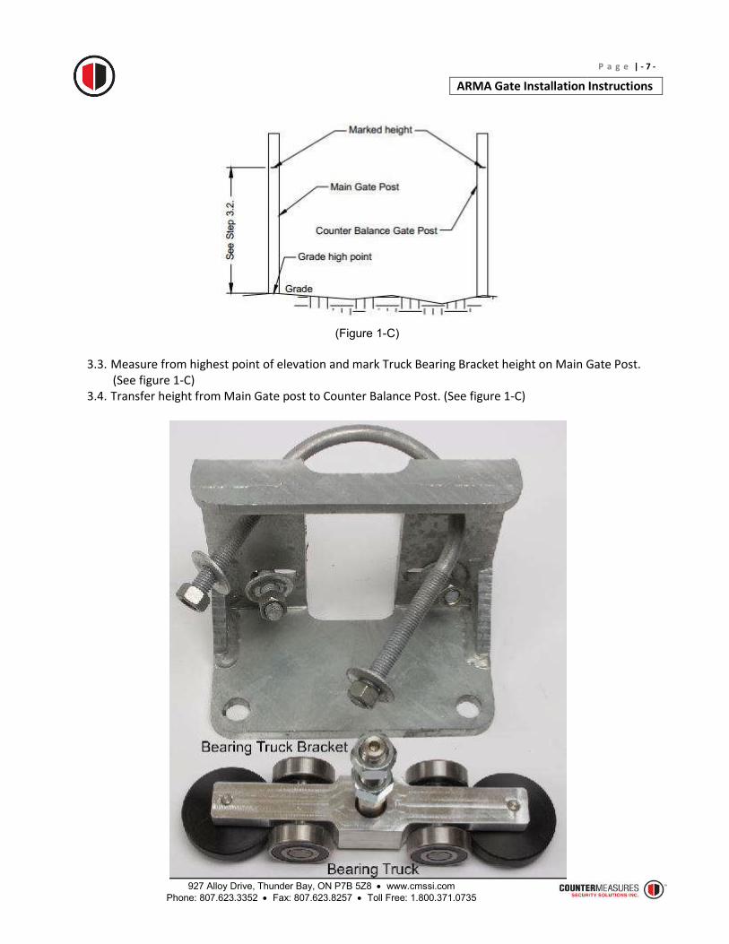
3.3. Measure from highest point of elevation and mark Truck Bearing Bracket height on Main Gate Post.
(See figure 1-C) 3.4. Transfer height from Main Gate post to Counter Balance Post. (See figure 1-C)

927 Alloy Drive, Thunder Bay, ON P7B 5Z8 www.cmssi.com Phone: 807.623.3352 Fax: 807.623.8257 Toll Free: 1.800.371.0735
P a g e | - 8 -
ARMA Gate Installation Instructions
(Figure 1-D)
3.5. Bearing Truck and Bearing Truck Bracket Kit. (See figure 1-D)

927 Alloy Drive, Thunder Bay, ON P7B 5Z8 www.cmssi.com Phone: 807.623.3352 Fax: 807.623.8257 Toll Free: 1.800.371.0735
P a g e | - 9 -
ARMA Gate Installation Instructions
(Figure 1-E)
3.6. For ease of installation, turn 5/8” Regular Hex Head Nut on Bearing Truck until it bottoms out with
unthreaded portion of shaft. (See figure 1-E)
(Figure 1-F)
3.7. Attach Bearing Truck to inside hole of Truck Bearing Bracket by removing 5/8” Locknut, then slide shaft
through hole and screw on 5/8” Locknut. (See figure 1-F). Install on the Main Gate post. 3.8. Attach Bearing Truck to inside hole of Truck Bearing Bracket by removing 5/8” Locknut, then slide shaft
through hole and screw on 5/8” Locknut. (See figure 1-F). Install on the Counter Balance Gate post.

927 Alloy Drive, Thunder Bay, ON P7B 5Z8 www.cmssi.com Phone: 807.623.3352 Fax: 807.623.8257 Toll Free: 1.800.371.0735
P a g e | - 10 -
ARMA Gate Installation Instructions
(Figure 1-G)
3.9. Ensure Truck Assemblies are installed on the secured side of Gate Posts. (See Figure 1-G) 3.10. Install Main Gate Truck Assembly to Main Gate Post with top flange in line with location mark and tighten
1/2” Hex Nuts. (See Figure 1-G) 3.11. Install Counter Balance Gate Truck Assembly to Counter Balance Gate Post with top flange in line with
location mark and tighten 1/2” Hex Nuts. (See Figure 1-G) 3.12. Final leveling of Gate Frame Segment will take place after splice. (See Figure 1-G)

927 Alloy Drive, Thunder Bay, ON P7B 5Z8 www.cmssi.com Phone: 807.623.3352 Fax: 807.623.8257 Toll Free: 1.800.371.0735
P a g e | - 11 -
ARMA Gate Installation Instructions
4. Gate Frame Segment Splice and Installation
4.1. Mesh Gate Frame Segment(s) per industry standard prior to hanging. 4.2. Always hang largest segment first. 4.3. Hang first Gate Frame Segment starting from Main Gate Post Truck Assembly through to Counter
Balance Gate Truck Assembly. (See Figure 1-J and 1-K)
(Figure 1-J)
(Figure 1-K)

927 Alloy Drive, Thunder Bay, ON P7B 5Z8 www.cmssi.com Phone: 807.623.3352 Fax: 807.623.8257 Toll Free: 1.800.371.0735
P a g e | - 12 -
ARMA Gate Installation Instructions
4.4. The following splice steps are needed for multiple gate segments only. Otherwise proceed to step 5, End
Cap Installation. 4.5. To prevent installed Gate Frame Segment from traveling during splice step, secure it to Main Gate Post.
(Figure 1-L)
4.6. Splice Kit. (See figure 1-L) 4.7. When attaching Splice Kit, start with installed Gate Frame Segment at Main Gate Post Side.
(Figure 1-M)

927 Alloy Drive, Thunder Bay, ON P7B 5Z8 www.cmssi.com Phone: 807.623.3352 Fax: 807.623.8257 Toll Free: 1.800.371.0735
P a g e | - 13 -
ARMA Gate Installation Instructions
4.8. Orientate threaded holes on Splice Bar with counter sunk holes on Top Rail. (See figure 1-M)
(Figure 1-N)
4.9. Insert Splice Bar into open cavity of Top Rail and align holes. (See figure 1-N)
(Figure 1-P)
4.10. Secure Splice Bar to Top Rail using 3/8” Flat Head Counter Sunk Screw 5 places and tighten fully with
7/32” Allen Wrench. (See figure 1-P)
927 Alloy Drive, Thunder Bay, ON P7B 5Z8 www.cmssi.com Phone: 807.623.3352 Fax: 807.623.8257 Toll Free: 1.800.371.0735
P a g e | - 14 -
ARMA Gate Installation Instructions
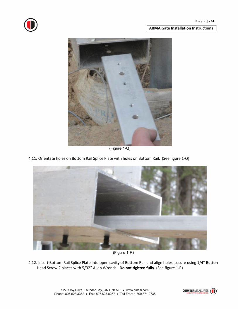
(Figure 1-Q)
4.11. Orientate holes on Bottom Rail Splice Plate with holes on Bottom Rail. (See figure 1-Q)
(Figure 1-R)
4.12. Insert Bottom Rail Splice Plate into open cavity of Bottom Rail and align holes, secure using 1/4” Button
Head Screw 2 places with 5/32” Allen Wrench. Do not tighten fully. (See figure 1-R)

927 Alloy Drive, Thunder Bay, ON P7B 5Z8 www.cmssi.com Phone: 807.623.3352 Fax: 807.623.8257 Toll Free: 1.800.371.0735
P a g e | - 15 -
ARMA Gate Installation Instructions
(Figure 1-S)
4.13. Join the next Gate Frame Segment to installed section by lifting it into place and sliding Top Rail and
Bottom Rail on to corresponding splice plates. (See figure 1-S)

927 Alloy Drive, Thunder Bay, ON P7B 5Z8 www.cmssi.com Phone: 807.623.3352 Fax: 807.623.8257 Toll Free: 1.800.371.0735
P a g e | - 16 -
ARMA Gate Installation Instructions
(Figure 1-T)
4.14. Use 3/8” Pin Punch in unthreaded hole to guide the two Gate Frame Segments into proper alignment.
(See figure 1-T)
(Figure 1-U)
4.15. Secure Top Rail to Splice Bar with remaining 3/8” Flat Head Counter Sunk Screw 5 places and tighten
fully with 7/32” Allen Wrench. (See figure 1-U)
(Figure 1-V)
4.16. Secure Bottom Rail Splice to Plate with remaining 1/4” Button Head Screw 2 places. Tighten fully all 4
Screws with 5/32” Allen Wrench. (See figure 1-V)

927 Alloy Drive, Thunder Bay, ON P7B 5Z8 www.cmssi.com Phone: 807.623.3352 Fax: 807.623.8257 Toll Free: 1.800.371.0735
P a g e | - 17 -
ARMA Gate Installation Instructions
(Figure 1-W)
4.17. Install Splice Corner Bracket to Top Rails with 1/4” Flat Head Counter Sunk Screw 4 places. Tighten
fully with 5/32” Allen Wrench. (See figure 1-W) 4.18. Repeat splice procedure as required.

927 Alloy Drive, Thunder Bay, ON P7B 5Z8 www.cmssi.com Phone: 807.623.3352 Fax: 807.623.8257 Toll Free: 1.800.371.0735
P a g e | - 18 -
ARMA Gate Installation Instructions
5. Top and Bottom End Cap Installation
(See figure 1-X)
5.1. Top and Bottom Rail End Cap Kits. (See figure 1-X)
(See figure 1-Y)
5.2. Stand outside of unsecured area and look towards the gate to determine left hand and right hand.
(Figure 1-Y) above shows left hand of Top Rail.

927 Alloy Drive, Thunder Bay, ON P7B 5Z8 www.cmssi.com Phone: 807.623.3352 Fax: 807.623.8257 Toll Free: 1.800.371.0735
P a g e | - 19 -
ARMA Gate Installation Instructions
(See figure 1-Z)
5.3. Guide left hand Top Rail End Cap into position. (See figure 1-Z)
(Figure 2-A)
5.4. Secure End Cap to Top Rail with 3/8” Flat Head Counter Sunk Screw and tighten fully with 7/32” Allen Wrench. (See figure 2-A)

927 Alloy Drive, Thunder Bay, ON P7B 5Z8 www.cmssi.com Phone: 807.623.3352 Fax: 807.623.8257 Toll Free: 1.800.371.0735
P a g e | - 20 -
ARMA Gate Installation Instructions
(Figure 2-B)
5.5. Insert 3/8” x 6.500” long Hex Head Cap Screw through holes on the side of Top Rail and screw on 3/8”
Nylon Insert Hex Nut and tighten fully. (See figures 2-B)
(Figure 2-C)
5.6. Guide left hand Bottom Rail End Cap into position. (See figure 2-C)

927 Alloy Drive, Thunder Bay, ON P7B 5Z8 www.cmssi.com Phone: 807.623.3352 Fax: 807.623.8257 Toll Free: 1.800.371.0735
P a g e | - 21 -
ARMA Gate Installation Instructions
(Figure 2-D)
5.7. Secure Bottom End Cap to Bottom Rail with 1/4” Button Head Screw and tighten fully with 5/32” Allen
Wrench. (See figure 2-D) 5.8. Repeat End Cap Installation procedure for right side.

927 Alloy Drive, Thunder Bay, ON P7B 5Z8 www.cmssi.com Phone: 807.623.3352 Fax: 807.623.8257 Toll Free: 1.800.371.0735
P a g e | - 22 -
ARMA Gate Installation Instructions
6. Leveling ARMA Gate
6.1. Center the Gate between Main Gate Post and Counter Balance Post then place a level in the middle of
Top Rail.
(Figure 2-F)
6.2. Adjust 5/8” Regular Hex Head Nut and Hex Head Lock Nut on Bearing Truck shaft until the gate is level.
(See figure 2-F) 6.3. For larger adjustments, loosen off U-Bolt 1/2” Hex Nuts and raise or lower the Bearing Truck Bracket by
striking it with a mallet to desired height then retighten nuts. (See figure 2-F) 6.4. Complete any fine tuning by adjusting 5/8” Regular Hex Head Nut and Hex Head Lock Nut on Bearing
Truck shaft. (See figure 2-F)
927 Alloy Drive, Thunder Bay, ON P7B 5Z8 www.cmssi.com Phone: 807.623.3352 Fax: 807.623.8257 Toll Free: 1.800.371.0735
P a g e | - 23 -
ARMA Gate Installation Instructions
7. Roller Guide Assembly Installation
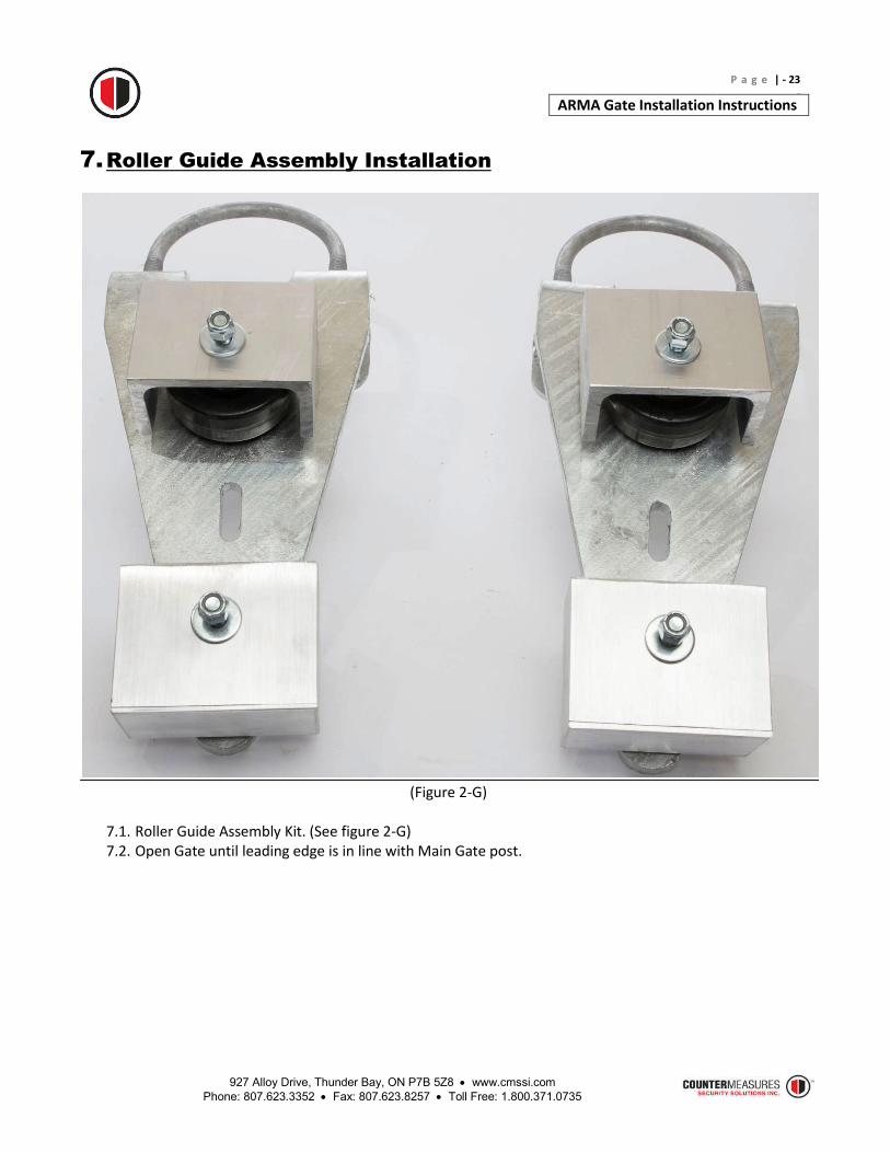
(Figure 2-G)
7.1. Roller Guide Assembly Kit. (See figure 2-G) 7.2. Open Gate until leading edge is in line with Main Gate post.

927 Alloy Drive, Thunder Bay, ON P7B 5Z8 www.cmssi.com Phone: 807.623.3352 Fax: 807.623.8257 Toll Free: 1.800.371.0735
P a g e | - 24 -
ARMA Gate Installation Instructions
(Figure 2-H)
7.3. Take wheel guards off by removing 3/8” Hex Locknut and 3/8” Washer from Roller Guide Assembly and
set aside. (Figure 2-H)
927 Alloy Drive, Thunder Bay, ON P7B 5Z8 www.cmssi.com Phone: 807.623.3352 Fax: 807.623.8257 Toll Free: 1.800.371.0735
P a g e | - 25 -
ARMA Gate Installation Instructions
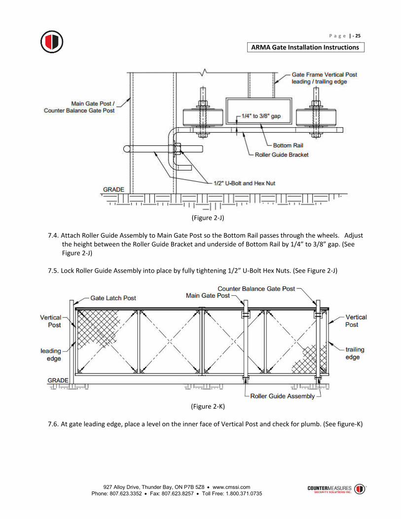
(Figure 2-J)
7.4. Attach Roller Guide Assembly to Main Gate Post so the Bottom Rail passes through the wheels. Adjust
the height between the Roller Guide Bracket and underside of Bottom Rail by 1/4” to 3/8” gap. (See Figure 2-J)
7.5. Lock Roller Guide Assembly into place by fully tightening 1/2” U-Bolt Hex Nuts. (See Figure 2-J)
(Figure 2-K)
7.6. At gate leading edge, place a level on the inner face of Vertical Post and check for plumb. (See figure-K)

927 Alloy Drive, Thunder Bay, ON P7B 5Z8 www.cmssi.com Phone: 807.623.3352 Fax: 807.623.8257 Toll Free: 1.800.371.0735
P a g e | - 26 -
ARMA Gate Installation Instructions
(Figure 2-M)
7.7. Position the required guide wheel to hold the gate in plumb position and tighten fully 3/8” Hex Head
Cap Screw and 3/8” Hex Nut. The gate is now locked into place. (Figure 2-M) 7.8. Position the other guide wheel with a gap of approximately 1/8” between wheel and Bottom Rail and
tighten fully 3/8” Hex Head Cap Screw and 3/8” Hex Nut. (Figure 2-M) 7.9. Reinstall wheel guards as shown and tighten fully 3/8” Hex Head Cap Screw and 3/8” Hex Locknut.
(See figure 2-M) 7.10. Close the gate completely prior to installing Counter Balance Gate Post Roller Guide Assembly. 7.11. Attach Roller Guide Assembly to Counter Balance Gate Post so the Bottom Rail passes through the
wheels. Adjust the height between Roller Guide Bracket and the underside of Bottom Rail by 1/4” to 3/8” gap. (See Figure 2-J)
7.12. Lock Roller Guide Assembly into place by fully tightening 1/2” U-Bolt Hex Nuts. (See Figure 2-J) 7.13. At gate trailing edge, place a level on the inner face of Vertical Post and check for plumb.
(See figure 2-K) 7.14. See step 7.7 (Figure 2-M) 7.15. See step 7.8 (Figure 2-M) 7.16. See step 7.9 (Figure 2-M)
927 Alloy Drive, Thunder Bay, ON P7B 5Z8 www.cmssi.com Phone: 807.623.3352 Fax: 807.623.8257 Toll Free: 1.800.371.0735
P a g e | - 27 -
ARMA Gate Installation Instructions
8. Gate Assembly Tensioning
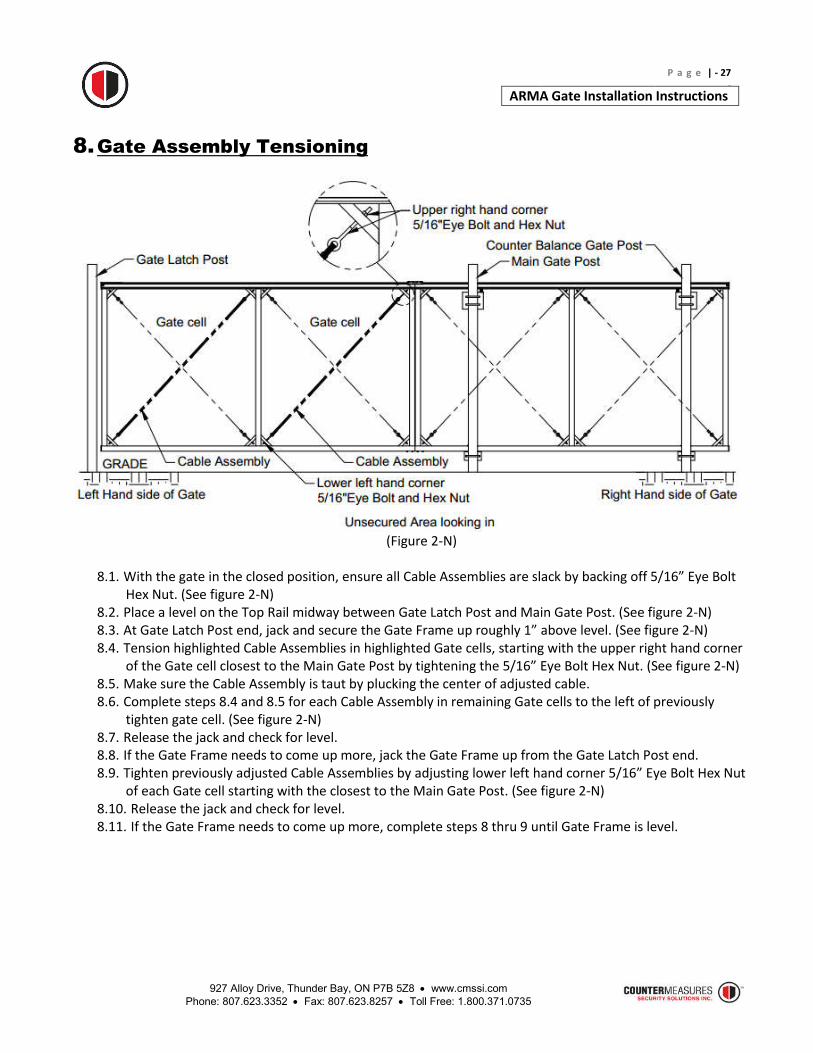
(Figure 2-N)
8.1. With the gate in the closed position, ensure all Cable Assemblies are slack by backing off 5/16” Eye Bolt
Hex Nut. (See figure 2-N) 8.2. Place a level on the Top Rail midway between Gate Latch Post and Main Gate Post. (See figure 2-N) 8.3. At Gate Latch Post end, jack and secure the Gate Frame up roughly 1” above level. (See figure 2-N) 8.4. Tension highlighted Cable Assemblies in highlighted Gate cells, starting with the upper right hand corner
of the Gate cell closest to the Main Gate Post by tightening the 5/16” Eye Bolt Hex Nut. (See figure 2-N) 8.5. Make sure the Cable Assembly is taut by plucking the center of adjusted cable. 8.6. Complete steps 8.4 and 8.5 for each Cable Assembly in remaining Gate cells to the left of previously
tighten gate cell. (See figure 2-N) 8.7. Release the jack and check for level. 8.8. If the Gate Frame needs to come up more, jack the Gate Frame up from the Gate Latch Post end. 8.9. Tighten previously adjusted Cable Assemblies by adjusting lower left hand corner 5/16” Eye Bolt Hex Nut
of each Gate cell starting with the closest to the Main Gate Post. (See figure 2-N) 8.10. Release the jack and check for level. 8.11. If the Gate Frame needs to come up more, complete steps 8 thru 9 until Gate Frame is level.

927 Alloy Drive, Thunder Bay, ON P7B 5Z8 www.cmssi.com Phone: 807.623.3352 Fax: 807.623.8257 Toll Free: 1.800.371.0735
P a g e | - 28 -
ARMA Gate Installation Instructions
(Figure 2-P)
8.12. Open the gate completely. (See figure 2-P) 8.13. Place a level on the Top Rail midway between Counter Balance Gate Post and trailing edge of Gate
Frame. (See figure 2-P) 8.14. Jack up and secure Gate Frame from trailing edge roughly 1” above level. (See figure 2-P) 8.15. Tension from highlighted Cable Assemblies in highlighted Gate cells, starting with the upper Left hand
corner of the Gate cell closest to the Counter Balance Gate Post by tightening the 5/16” Eye Bolt Hex Nut. (See figure 2-N)
8.16. Make sure the Cable Assembly is taut by plucking the center of adjusted cable. 8.17. Complete steps 8.15 and 8.16 for each Cable Assembly in remaining gate cells to the right of previously
tighten gate cell. (See figure 2-N) 8.18. Release the jack and check for level. 8.19. If the Gate Frame needs to come up more, jack up from the trailing edge. 8.20. Tighten previously adjusted Cable Assemblies by adjusting lower right hand corner 5/16” Eye Bolt Hex
Nut of each gate cell starting with the closest to the Counter Balance Gate Post. (See figure 2-N) 8.21. Release the jack and check for level. 8.22. If the Gate Frame needs to come up more, complete steps 8.19 thru 8.20 until Gate Frame is level. 8.23. With the Gate Frame level, tighten remaining loose Cable Assemblies. IMPORTANT, do not over
tighten as this will cause the Gate Frame to lose level.
927 Alloy Drive, Thunder Bay, ON P7B 5Z8 www.cmssi.com Phone: 807.623.3352 Fax: 807.623.8257 Toll Free: 1.800.371.0735
P a g e | - 29 -
ARMA Gate Installation Instructions
9. Closure Guide Assembly Installation
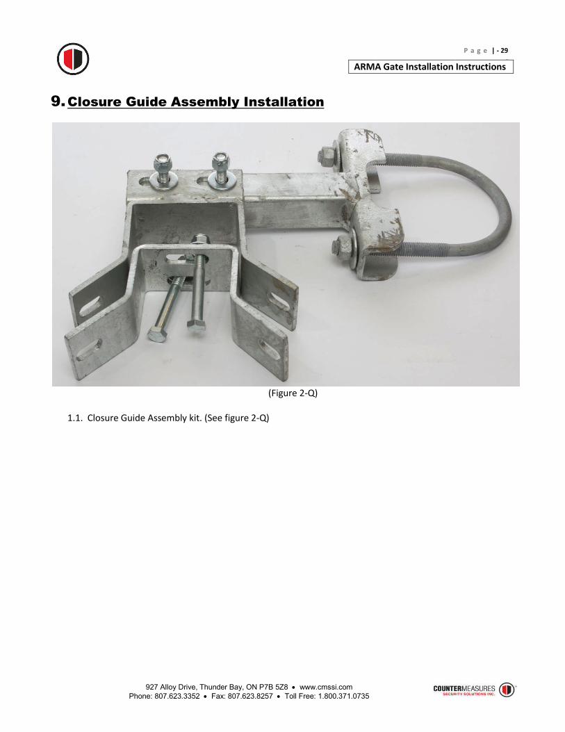
(Figure 2-Q)
1.1. Closure Guide Assembly kit. (See figure 2-Q)

927 Alloy Drive, Thunder Bay, ON P7B 5Z8 www.cmssi.com Phone: 807.623.3352 Fax: 807.623.8257 Toll Free: 1.800.371.0735
P a g e | - 30 -
ARMA Gate Installation Instructions
(Figure 2-R)
1.2. Closure Guide Assembly installation height per customer requirement. 1.3. Attach Closure Guide Assembly to Gate Latch Post 1 as shown and fully tighten 1/2” U-Bolt Hex Nuts.
(See Figure 2-R)
(Figure 2-S)
1.4. Line center of Closure Guide opening with the center of Gate Frame Vertical Post, tighten fully 3/8” Hex
Head Cap Screw and 3/8”Hex Nut. (See figure 2-S)
927 Alloy Drive, Thunder Bay, ON P7B 5Z8 www.cmssi.com Phone: 807.623.3352 Fax: 807.623.8257 Toll Free: 1.800.371.0735
P a g e | - 31 -
ARMA Gate Installation Instructions
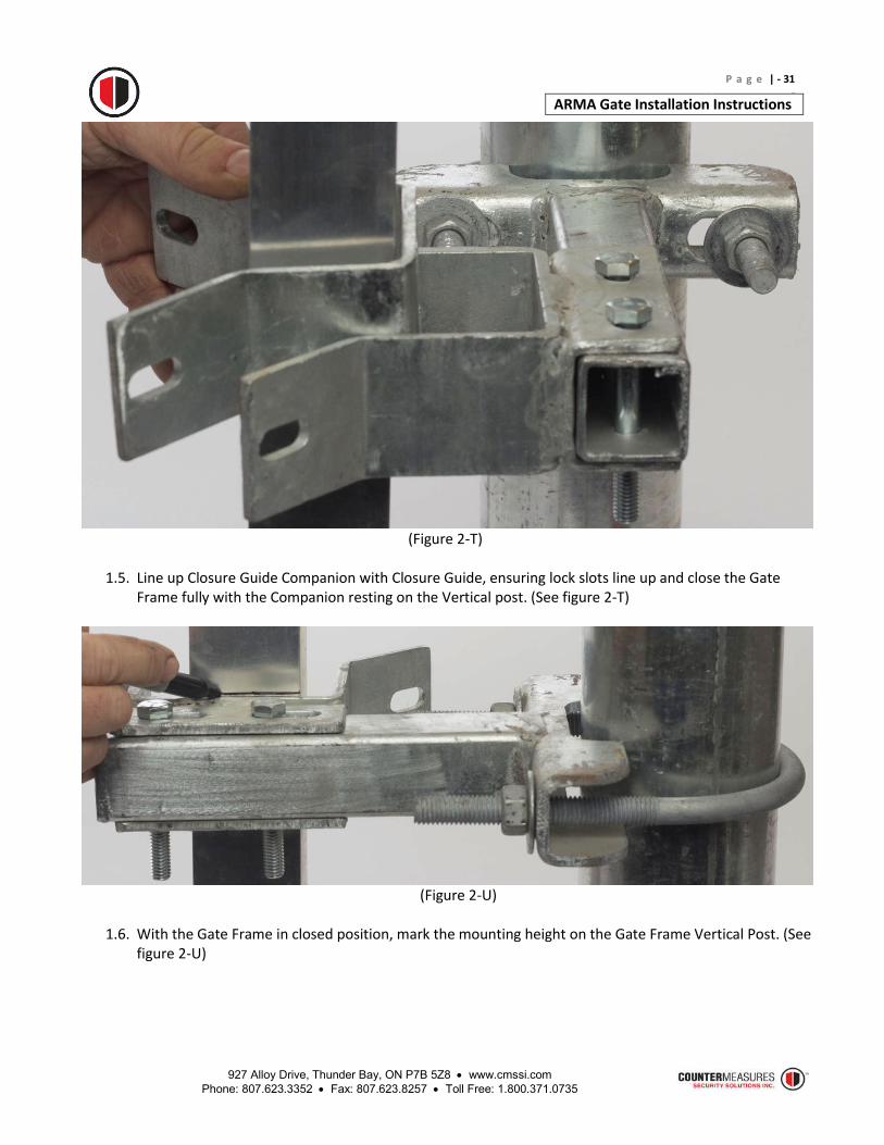
(Figure 2-T)
1.5. Line up Closure Guide Companion with Closure Guide, ensuring lock slots line up and close the Gate
Frame fully with the Companion resting on the Vertical post. (See figure 2-T)
(Figure 2-U)
1.6. With the Gate Frame in closed position, mark the mounting height on the Gate Frame Vertical Post. (See
figure 2-U)

927 Alloy Drive, Thunder Bay, ON P7B 5Z8 www.cmssi.com Phone: 807.623.3352 Fax: 807.623.8257 Toll Free: 1.800.371.0735
P a g e | - 32 -
ARMA Gate Installation Instructions
(Figure 2-V)
1.7. Open Gate Frame enough to mark the top Companion hole on the Gate Frame Vertical Post, then
remove companion. (See figure 2-V) 1.8. Drill hole through Gate Frame Vertical Post with 3/8” drill bit.
(Figure 2-W)
1.9. Use 3/8” Hex Head Cap Screw, Flat Washer and Hex Locknut to secure Companion to Gate Frame
Vertical Post. Drill remaining hole and install 3/8” Screw, Washer and Locknut (See figure 2-W)

927 Alloy Drive, Thunder Bay, ON P7B 5Z8 www.cmssi.com Phone: 807.623.3352 Fax: 807.623.8257 Toll Free: 1.800.371.0735
P a g e | - 33 -
ARMA Gate Installation Instructions
10. Optional Barbed Wire Kit Installation
(Figure 2-Y)
10.1. Barbed Wire Kit. (See figure 2-Y)
(Figure 2-Z)
10.2. Stand in unsecured area facing the Gate to determine left and right hand. (See figure 2-Z) 10.3. Install Left and Right hand Barb Arm Brackets 2.000” from the end of Top Rail. (See figure 2-Z) 10.4. Space Intermediate Barb Arms evenly across Top Rail with gap not to exceed 10ft. (See figure 2-Z)

927 Alloy Drive, Thunder Bay, ON P7B 5Z8 www.cmssi.com Phone: 807.623.3352 Fax: 807.623.8257 Toll Free: 1.800.371.0735
P a g e | - 34 -
ARMA Gate Installation Instructions
(Figure 3-A)
10.5. Center left/right hand Barb Arm Bracket over recess to the left of Bearing Truck and install to Top Rail
with 3 x 1/4” Hex Head Cap Screws Self Drilling. (See figure 3-A) 10.6. Repeat step 10.5 for Intermediate Barb Arms and install to Top Rail with 2 x 1/4” Hex Head Cap Screws
Self Drilling. (See figure 3-A)
(Figure 3-B)
10.7. Install 3 strands of Barbed Wire Using standard fencing procedure and tension with the supplied 5/16”
Eye Bolts attached to the Left or right hand Barb Arm Bracket.

927 Alloy Drive, Thunder Bay, ON P7B 5Z8 www.cmssi.com Phone: 807.623.3352 Fax: 807.623.8257 Toll Free: 1.800.371.0735
P a g e | - 35 -
ARMA Gate Installation Instructions
11. Gap Filler Installation
11.1. Install Gap Filler to Main Gate Post with 5/16” Carriage Bolt and Hex Nut 1.25” from top of Wheel Guard. (See figure 3-C)
(Figure 3-C)
12. Function Test
12.1. Open and close the Gate several times to ensure it is not binding or meeting resistance while traveling. The Gate should easily travel the full distance with the force applied by 2 fingers.