Aluminium plate-fin heat exchangers. · Raw material Raw material Parting sheets Fins Sidebars...
9
Aluminium plate-fin heat exchangers. Proven technology in a variety of designs.
Transcript of Aluminium plate-fin heat exchangers. · Raw material Raw material Parting sheets Fins Sidebars...
Aluminium plate-fin heat exchangers.Proven technology in a variety of designs.

One of the world’s largest brazing capacities
Our PFHEs are manufactured at our global production facilities using vacuum brazing technology. One of the largest brazing capacities in the world gives us the flexibility to meet customer demand for rapid turnarounds. Regardless of the complexity and size of the assembly, we can deliver sophisticated solutions designed to the highest quality standards – on time, on spec and on budget.
Broad experience base
We deliver PFHEs to a broad customer base, including Linde entities around the world, third parties and design institutes. The fact that we gain hands-on experience using our own equipment gives us a decisive edge, enabling us to channel these operational insights into design fine-tuning and the continued exploration of optimisation potential.
Know-how sharing
Our customer-centric teams bring together professional engineers, skilled employees and trained maintenance and service staff. These highly skilled and specialised teams travel the globe to support our customers during the entire equipment lifecycle - from installation through start-up to maintenance and support.
Our customers know that our service team is only ever a call away and that they can always rely on the vast and bundled experience we have gained over the years to solve even the most stubborn of challenges. These include processes that demand design pressures up to 130 bar, temperatures as low as 3 K and temperature differences of less than 1 K.
03
Highly skilled welders ensure the highest quality products.
Linde – partner of choice.
Proven expertise.
Designed to last
Since 1981, we have built over 12,000 vacuum-brazed plate-fin heat exchangers (PFHE) at our sites in Germany and China. Around the world, these Linde PFHEs enjoy a strong reputation for their market-leading quality and technical reliability across a wide variety of cryogenic applications. The fact that many of these PFHEs are still in operation after decades of service bears clear testimony to the enduring nature of our designs.
As one of the founding members of the Aluminium Plate-Fin Heat Exchanger Manufacturer‘s Association (ALPEMA), we have made a valuable contribution to the advancement of PFHE technology over the years.
Winning combination
Our PFHEs are designed to the individual needs of each customer. You can rely on our engineering experts to factor in your thermal and hydraulic performance requirements along with your availability and lifetime expectations while keeping investment costs and operation costs to a minimum.
By combining optimised design with proven technologies and the highest quality standards, we offer our customer state-of-the-art solutions. Our experts can also increase the lifetime of your equipment by analysing your process and reducing thermal and mechanical stress to the equipment.
“ Understanding our customers’ needs, offering a value-creating solution and executing are key capabilities at Linde Engineering.”Jürgen NowickiManaging Director Member of the Board of Directors
02
Linde is known for its uncompromising quality standards.
Linde manufactures PFHEs at its sites in Germany and China.
Partner of choiceProven expertise
05Brazing technology
Familiar CO₂ applications include the carbonation of beverages.
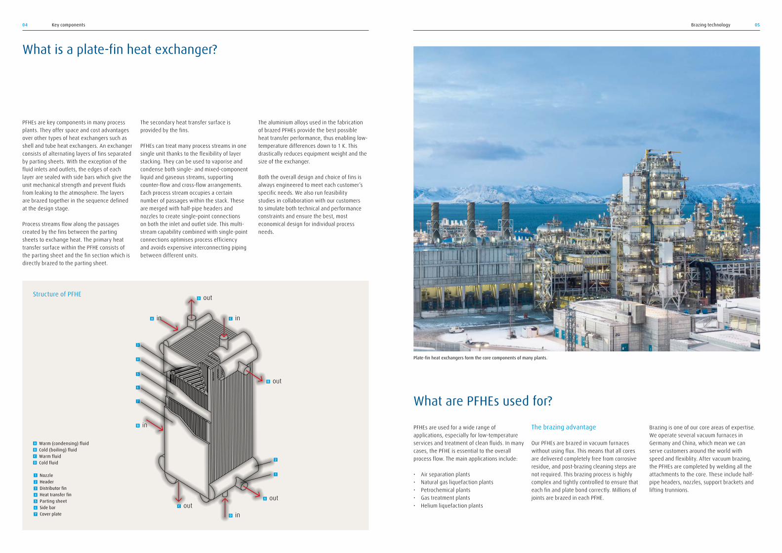
Plate-fin heat exchangers form the core components of many plants.
PFHEs are used for a wide range of applications, especially for low-temperature services and treatment of clean fluids. In many cases, the PFHE is essential to the overall process flow. The main applications include:
• Air separation plants • Natural gas liquefaction plants• Petrochemical plants• Gas treatment plants • Helium liquefaction plants
The brazing advantage
Our PFHEs are brazed in vacuum furnaces without using flux. This means that all cores are delivered completely free from corrosive residue, and post-brazing cleaning steps are not required. This brazing process is highly complex and tightly controlled to ensure that each fin and plate bond correctly. Millions of joints are brazed in each PFHE.
Brazing is one of our core areas of expertise. We operate several vacuum furnaces in Germany and China, which mean we can serve customers around the world with speed and flexiblity. After vacuum brazing, the PFHEs are completed by welding all the attachments to the core. These include half-pipe headers, nozzles, support brackets and lifting trunnions.
What are PFHEs used for?
04 Key components
What is a plate-fin heat exchanger?
The secondary heat transfer surface is provided by the fins.
PFHEs can treat many process streams in one single unit thanks to the flexibility of layer stacking. They can be used to vaporise and condense both single- and mixed-component liquid and gaseous streams, supporting counter-flow and cross-flow arrangements. Each process stream occupies a certain number of passages within the stack. These are merged with half-pipe headers and nozzles to create single-point connections on both the inlet and outlet side. This multi-stream capability combined with single-point connections optimises process efficiency and avoids expensive interconnecting piping between different units.
PFHEs are key components in many process plants. They offer space and cost advantages over other types of heat exchangers such as shell and tube heat exchangers. An exchanger consists of alternating layers of fins separated by parting sheets. With the exception of the fluid inlets and outlets, the edges of each layer are sealed with side bars which give the unit mechanical strength and prevent fluids from leaking to the atmosphere. The layers are brazed together in the sequence defined at the design stage.
Process streams flow along the passages created by the fins between the parting sheets to exchange heat. The primary heat transfer surface within the PFHE consists of the parting sheet and the fin section which is directly brazed to the parting sheet.
The aluminium alloys used in the fabrication of brazed PFHEs provide the best possible heat transfer performance, thus enabling low-temperature differences down to 1 K. This drastically reduces equipment weight and the size of the exchanger.
Both the overall design and choice of fins is always engineered to meet each customer’s specific needs. We also run feasibility studies in collaboration with our customers to simulate both technical and performance constraints and ensure the best, most economical design for individual process needs.
1 Nozzle2 Header3 Distributor fin4 Heat transfer fin5 Parting sheet6 Side bar7 Cover plate
D out
A in C in
B out
B in
C outD in
A out
1
2
3
4
5
7
6
Structure of PFHE
A Warm (condensing) fluidB Cold (boiling) fluidC Warm fluidD Cold fluid

Raw material
Raw material
Parting sheets Fins Sidebars
Brazing
Measuring, cutting
Measuring, cutting
Assembly
Heat exchanger
Vacuum furnace
Stamping, measuring, cutting Measuring, cutting
Washing Washing Washing
Stacking
Raw material Raw material
Testing
Design versatility
We use a variety of materials, fins and assembly models to match individual performance needs and cost constraints. Our compact designs ensure the best surface to volume ratio – more than 2000 m²/m³ are possible. This allows us to reduce weight, aluminium requirements and support structures. In addition, to minimise the number of exchangers required we build heat exchangers that are up to 8.2 metres in length, 1.5 metres in width and 3.4 metres in height.
The right materials
We use a variety of aluminium alloys to ensure optimum performance. These include
type 3003 for cores and 5083 for headers and nozzles. Customers can also request ASTM 5454/EN AW 5454. These materials are also suitable for higher temperatures (up to +93°C). Depending on the design code applicable to pressure vessels (i.e. the ASME code or EN code), we choose the materials and combinations best suited to individual performance needs.
Variety of fin corrugations We use a variety of fins with different corrugations and variable heights and densities to match hydraulic and thermal performance characteristics with individual needs. The geometry of these fins has been gradually optimised drawing on the experience gained in the field over the last
35 years. Different fin types can also be combined in a single stream.
Features for improved mercury resistance
Based on our long-standing, hands-on experience, we incorporate a range of mercury-tolerant features into our PFHE designs to provide the highest possible levels of mercury resistance. We generally recommend operating PFHEs within the range stated in ALPEMA. Above this range – depending on the actual design conditions – we often advise building in guard beds in order to minimise the risk of material corrosion as a result of mercury.
0706 Manufacturing process
PFHEs are manufactured from raw materials in a multi-step process with all steps rigorously controlled to ensure the highest quality. After the headers and nozzles have been welded to the core, the completed heat exchangers are subjected to non-destructive testing. This includes hydraulic or pneumatic pressure testing and leak testing.
Perfect fit.
Different fin types mean we can optimise the thermal and hydraulic performance to customer needs. We cover the full spectrum from plain through perforated to serrated fins, and from stand-alone PFHEs through manifold assemblies to block-in-shells and coldboxes.This ensures that we can provide the perfect fit for each customer’s application challenges, performance needs and budgetary constraints. Customers can also rely on our experts for process consulting support to optimise overall system design and help reduce operating costs further down the line.
Designed for individual needs
Serrated fin . Perforated fin. Plain fin.
Multi-step fabrication process

Single units
Our PFHEs can be supplied as single units with stub pipes, material transitions plus aluminium or stainless steel flanges for connection to the plant piping.
Manifold assemblies
If the required heat transfer performance cannot be achieved with a single PFHE, we offer manifold assemblies. These PFHE assemblies are batteries of two or more PFHEs. This complete heat exchanger system can be transported in a steel frame or in a combined transportation/operation frame for later use.
Coldboxes
One or more PFHEs are installed in a steel casing (normally carbon steel) which may include interconnect piping, phase separator vessels, rectification columns, appropriate valves and instruments as well as insulation material (perlite). The coldboxes are provided with flanges at the wall outlets for easy connection to on-site piping. Depending on the application, the coldbox footprint can be rectangular or circular. Coldbox advantages include:
→ These units are ready to operate, only perlite to be filled in. → No additional support structures are required. → The equipment integrated in the box is protected. → Insulation material can be replaced quickly and easily.
0908 Customised packaging options Advantages of block-in-shell units
Block-in-shell unit
A Gas in
B 2-phase inlet
B Gas out
A Liquid out
Shell
B DrainLevel
Block-in-shell units
Our block-in-shell units consist of one or more PFHEs installed in a steel shell. While matching the service of shell and tubular heat exchangers, these units offer a number of advantages:
→ Reduced temperature approach (less than 1 K), which results in energy savings.
→ Up to ten times greater heat transfer area per unit. → Smaller size, weight and footprint. → Lower installation costs.
Packaging options.
Read more:linde-engineering.com/plantcomponents
Our exchangers are also available in a variety of delivery modes to suit individual needs. Customers can choose between single exchangers and fully integrated assemblies and coldboxes.
Helium liquefaction unit.
A Condensing fluid B Boiling fluid
PFHE
Over 12,000 premium-quality plate-fin heat exchangers delivered since production started in 1981.

10 Technical specifications Aluminium plate-fin heat exchangers 11
Quality management and inspection
Quality management is an essential part of our company strategy.
Linde is certified according to:
• EN ISO 9001/EN ISO 14001• German Pressure Vessel Rules (AD-HP0)• ASME (U, U2) • National Board (NB, R)• Manufacture license of special
equipment (China)• Certificate of manufacture registration
of cylinder (Korea) Acceptance inspection is carried out by our own specialists and also by experts from various international inspection organisations, such as:
• TÜV (German Safety Inspectorate)• Arise • Others on request
Design standards
The process and mechanical design blueprint for PFHEs builds on our know-how as a leading engineering company for turnkey plants. We are a founding member of the Aluminium Plate-Fin Heat Exchanger Manufacturer‘s Association (ALPEMA) and also member of other international organisations such as HTRI and HTFS.
Equipment design and manufacturing, based on our customer‘s specifications and our own standards, are carried out in accordance with national and international standards such as:
• PED European Pressure Equipment Directive
• European standards• ASME Code• Chinese standards • Russian standards• And others
Technical data.
Ready for transportation.
Maximum dimensions per single heat exchanger: Width: 1.5 m Height: 3.4 m Length: 8.2 m Design temperature: -269°C to + 93°C (200°F)
Design pressure: Up to approx. 130 bar (1886 psig)
Materials: Core: ASTM 3003/EN AW 3003 Headers, nozzles, flanges: ASTM 5083/EN AW 5083 ASTM 5454/EN AW 5454
Aluminium plate-fin heat exchangers
Quality management and inspection.

Contours of velocity magnitude (m/s).
100
90
70
60
50
40
30
20
00
Contours of total pressure (kPA).
104.0
103.5
103.5
102.5
102.0
101.5
101.0
100.5
100.0
1312 Full service spectrum Full service spectrum
Full service spectrum.
We offer a broad range of engineering, installation and aftersales services to support our customers from the initial design and simulation stage throughout the whole lifetime of the equipment.
Optimisation of PFHE lifetime expectancy
PFHE customers are generally keen to maximise temperature and pressure capabilities. Instead of applying low, standard operating limitations for dynamic temperature differences, we have developed special 3D simulation tools to explore all fine-tuning and optimisation potential during the design process.
Through steady-state and dynamic simulations, we calculate the thermo-hydraulic performance, also applying computational fluid dynamics and finite element analysis for the best possible outcomes.
However, changes in the plant’s operation or in the load of the heat exchanger often mean a deviation from the original design. In these cases, a dependable assessment of the heat exchanger’s reliability and safety must be made.
With LIBAS® (Linde Brazed Plate-fin Analysis of Stress), Linde has developed a system which is able to reliably calculate the lifetime of the Linde heat exchanger on the basis of its geometry and real load data. The system is based on the combination of thermofluid-dynamic simulation with a finite-element analysis and has been extensively validated by practical tests.
Finite element analysis (FEA) in action
As illustrated in the top left illustration, finite element analysis can be used to simulate all PFHE parts. We then use the geometry and process data to calculate the temperature profile (top right illustration). This, in turn, reveals the mechanical stresses that each part of the PFHE is exposed to (bottom left illustration).
Coverplate
Sidebar
Partingsheet
Header
Module_layer
Fin1
Fin2
Fin3
Fin4
Fin5
Fin6
Fin7
Fin8
Fin9
Fin10
28.5
13.1
-2.3
-17.7
-33.1
-48.5
-63.9
-79.3
-94.7
-110.1
-125.5
Temperature (˚C)
Stress (MPa)
LIBAS® is a registered trademark of The Linde Group.
Computational fluid dynamics (CFD) in action
We use CFD to simulate the flow distribution (from the nozzle into the half-pipe headers) and then calculate the velocities and pressure differences (as illustrated below). These insights allow us to optimise the layer arrangement in the core and thus extend the lifetime.

Aluminium plate-fin heat exchanger.
1514 Overview of service offerings Benefits at a glance
Operational services.
Our after-sales and field services can help you with everything from operational improvements and maintenance to periodic inspections at our manufacturing yard.
Field installationQualified and experienced erection engineers, fitters and welders are available to carry out and/or to supervise the installation of our PFHEs on site.
OperationOur thermodynamic, hydraulic, process and mechanical engineering specialists are always ready to support you with thermal and hydraulic problem analysis and operational improvements.
CleaningIf fouling or plugging in exchanger passages occurs, we can run an immediate analysis and present cleaning proposals. We can also supervise the cleaning process.
Manufacturing excellence
All plate-fin heat exchangers are manufactured at our Linde Engineering sites in China and Germany. Schalchen (Germany) has been manufacturing premium-quality plant components and modules for the past 60 years. With over 800 engineers and skilled workers, Schalchen also offers field installation and advice on operation. A specialised service crew is available for immediate and professional on-site assistance.
At our site in Dalian (China), we combine leading technologies from The Linde Group with our professional management skills to support our customers with top-quality products and value-added services.
To find out how your process plant can benefit from our world-class technologies, global reach and outstanding support services, visit linde-engineering.com/plantcomponents or contact your local Linde Engineering sales office.
Read more: linde-engineering.com/plantcomponents
Published by: Linde AGEngineering Division, Dr.-Carl-von-Linde-Strasse 6–14 82049 Pullach, GermanyPhone +49 89 7445-0, Fax +49 89 7445-4908 [email protected], www.linde-engineering.com
PFHE lifetime screening
Interdisciplinary workshop (description of scenarios)
Top-rating critical cases
The PFHE lifetime screening service is available for both Linde and third-party PFHEs. Building on our experience and proprietary software, we provide a qualitative rating of all scenarios, highlighting critical cases in particular.
Step 1
Rough criticality assessment
Step 2 Step 3
PFHE lifetime estimation
The PFHE lifetime estimation service is available only for Linde PFHEs. Building on our experience and proprietary software, we provide a quantitative rating of all scenarios, highlighting critical cases in particular and allowing us to predict lifetime expectancy of a PFHE.
Pre-selected cases Thermal/hydraulic simulation
Stress calculation/ fatigue analysis
Event counting/ Estimation of lifetime
Step 1 Step 2 Step 3 Step 4
Repair service Should a malfunction of your PFHE system occur, we have an emergency team that has the right qualifications, experience, certificates and tools to quickly help you with the required repair work. Moreover, we organise technology-based maintenance work for you, particularly the replacement or repair of a PFHE.
Your benefits • Qualified analysis and consulting based on our technical expertise.• Optimal execution of repairs by qualified manufacturing experts.• Optimal value for money and quick delivery of essential consumables.• Full aluminium welding expertise with all relevant certificates. Repairs and troubleshooting • Failure analysis and emergency service. • Welding work on aluminium components such as heat exchangers and coldboxes.• We provide the tools and equipment needed for the service on site.
Inspection and diagnosis • Review of the condition of your PFHE.
Manufacturing sites at Schalchen (Germany) and Dalian (China).
PFHE lifetime services
In addition, we offer lifetime screening and assessment analysis, fault reconstruction and operational screening services.
2231
7_LC
S_03
17
Plant engineering → Air separation plants → LNG and natural gas processing plants → Petrochemical plants → Hydrogen and synthesis gas plants → Adsorption and membrane plants → Cryogenic plants → Carbon capture and utilisation plants → Furnaces, fired heaters, incinerators
Component manufacturing → Coldboxes and modules → Coil-wound heat exchangers → Plate-fin heat exchangers → Cryogenic columns → Cryogenic storage tanks → Liquefied helium tanks and containers → Air-heated vaporisers → Water bath vaporisers → Spiral-welded aluminium pipes
Collaborate. Innovate. Deliver.
Linde’s Engineering Division is a leading player in the international plant engineering business. Across the globe, we have delivered more than 4,000 plants and cover every step in the design, project management and construction of turnkey industrial facilities. Our proven process and technology know-how plays an indispensable role in the success of our customers across multiple industries – from crude oil, natural gas extraction and refining to chemical and metal processing.
At Linde, we value trusted, lasting business relationships with our customers. We listen carefully and collaborate closely with you to meet your needs. This connection inspires us to develop innovative process technologies and equipment at our high-tech R&D centres, labs and pilot plants – designed in close collaboration with our strategic partners and delivered with passion by our employees working in more than 100 countries worldwide.
From the desert to the Arctic, from small- to world-scale, from standardised to customised builds, our specialists develop plant solutions that operate reliably and cost-effectively under all conditions. You can always rely on us to deliver the solutions and services that best fit your needs – anywhere in the world.
Discover how we can contribute to your success at www.linde-engineering.com
Get in touch with our component manufacturing team: Phone: +49 8621 85-6473, e-mail: [email protected]
Services → Revamps and plant modifications → Plant relocations → Spare parts → Operational support, troubleshooting
and immediate repairs → Long-term service contracts → Expert reviews for plants, operations
and spare part inventory → Operator training
Core competencies at a glance