
Alton Victorian greenhouse instructions
24
Alton Victorian Installation Instructions (for all models) 6’5”/2046mm Wide 7’7”/2414mm Wide 10’/3144mm Wide
-
Upload
the-greenhouse-people -
Category
Documents
-
view
227 -
download
7
description
Alton Victorian greenhouse instructions for all widths
Transcript of Alton Victorian greenhouse instructions
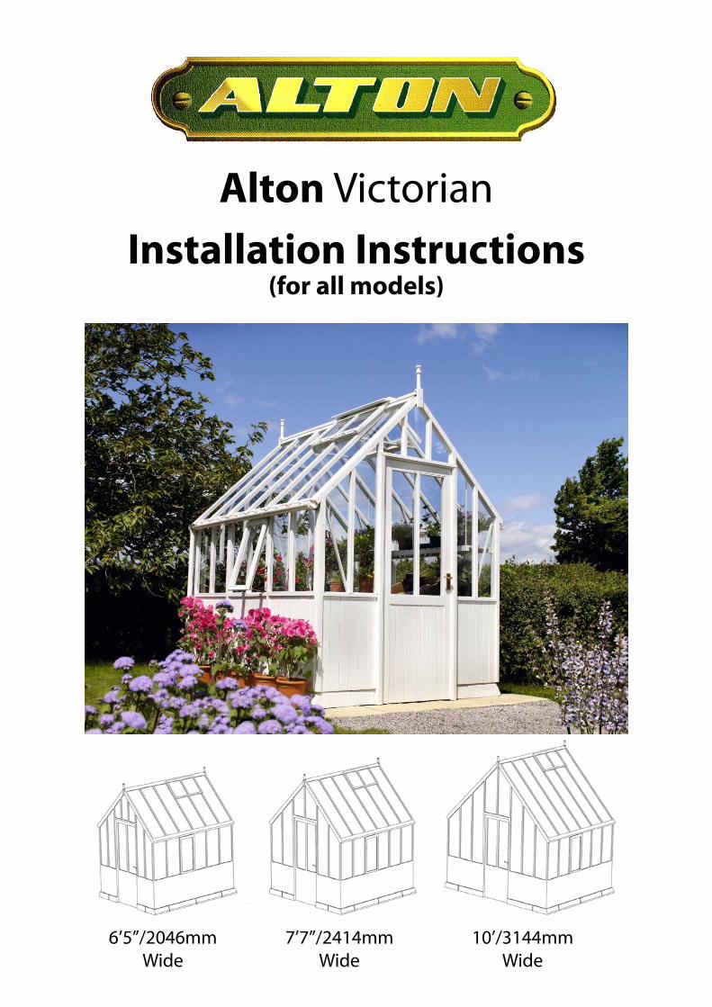
Alton Victorian Installation Instructions
(for all models)
6’5”/2046mm Wide
7’7”/2414mm Wide
10’/3144mm Wide

2
YOUR NEW CEDAR GREENHOUSE
Introduction Planning and Preparation
Optional Extras
Safety Advise
Fitting Service
Tools Required
Unpacking the Greenhouse
Thank you for buying an Alton Victorian Greenhouse. Please read carefully through these instructions before beginning to put your greenhouse up.
All of the illustrations relate to a 7’7”/2400mm wide x 10’5”/3156mm long Victorian Greenhouse. For other models you will have a greater or smaller number of side sections for your chosen model. Before you commence assembly of the frame it is advisable to pre-determine the layout of individual sections to ensure the roof vents are in the position you require. If you do not wish to cut one of the roof cover strips please avoid positioning a roof vent at the very end of the greenhouse. A bradawl should be used to pilot all screw holes, especially on the shelving and staging, to help prevent the timber from splitting. Sometimes the pre-drilled holes in the frames can be blocked - simply insert a screwdriver to clear them.
It is extremely important that you assemble your optional extras in the correct position. Throughout these instruction references will be made to each optional extra. Please refer to the appropriate page or leaflet for full details.
Before removing all the packaging please note the individual named pieces of greenhouse. This is not only a convenient way to check you have all the correct sections, but also to help you when determining the layout and assembly of your greenhouse. You will also notice all fixtures, nails, screws, bolts etc., come pre-packed and labelled for your convenience. If using a knife be careful not to cut into the wood. The plain gable end and the door gable end have carrying straps (pieces of timber) fixed to them and these should not be removed until after the greenhouse has been bolted together. The door gable end also has a transit strap nailed to the bottom of the door posts which must be removed as soon as this section is unwrapped.
It is advisable that the greenhouse should be assembled by two people. Particular care should be taken when handling glass and the wearing of gloves is strongly recommended. Favourable weather conditions should be chosen. Do not try to erect the building in windy conditions - the panels are difficult to handle in high winds. All side frames should be suitably propped until the roof frames are secured. Keep children and pets away until the work is finished. Take your time - rushing causes accidents
Please call your local dealer if you would like to have a quote for the erection of your greenhouse by an installer.
Drill & bits (for pilot holes), screwdrivers (slot and pozi-drive), spanners 10mm & 17mm, small hammer, pliers, spirit level, step ladder, tape measure, bradawl, silicone gun, saw & props.

3
SITING YOUR GREENHOUSE
Siting your greenhouse Site Preparation
You may have already considered the position of your new greenhouse and be aware of the general guidance given. But it may be advisable to consider the following advice: A flat level site is essential and further information on the preparation of the ground is given opposite. It is necessary to leave sufficient working room around your greenhouse when you’re putting it up and also to allow for the possible need to replace a piece of glass in the future. If possible try and leave a space of 2ft/610mm around the greenhouse. Locate the greenhouse where there is maximum amount of sunlight and avoid if possible any shade from trees, fences or other buildings. Over-hanging branches can be a particular nuisance and should be avoided. Choose a site where the greenhouse is relatively easy to get to and convenient to bring water to and possibly a supply of electricity. Finally, and most importantly, choose a site where your Alton Greenhouse will look right so that it will complement your garden.
It is essential that the concrete base kerbs are laid on firm level ground that is unlikely to let the greenhouse sink into it after a number of years. If the site for the greenhouse is not firm, level or well drained, it is advisable to lay concrete footings as illustrated (diagram 1), or lay a perimeter row of paving slabs. The depth of footings will depend on the nature of the ground on your site. For practical purposes a spade’s width and depth may be preferred.
Diagram 1

4
CONCRETE BASE KERBS
Base kerb dimensions
Standard Width: 6’5”
Standard Lengths
Internal External Width Length Width Length
5'4" 1792mm 1448mm 2046mm 1620mm 7'11" 1792mm 2225mm 2046mm 2397mm 10'5" 1792mm 2984mm 2046mm 3156mm 13' 1792mm 3778mm 2046mm 3950mm
15'5" 1792mm 4521mm 2046mm 4693mm 18' 1792mm 5299mm 2046mm 5401mm
20'5" 1792mm 6057mm 2046mm 6229mm
Standard Width: 7’7”
Standard Lengths
Internal External Width Length Width Length
5'4" 2160mm 1448mm 2414mm 1620mm 7'11" 2160mm 2225mm 2414mm 2397mm 10'5" 2160mm 2984mm 2414mm 3156mm 13' 2160mm 3778mm 2414mm 3950mm
15'5" 2160mm 4521mm 2414mm 4693mm 18' 2160mm 5299mm 2414mm 5401mm
20'5" 2160mm 6057mm 2414mm 6229mm
Standard Width: 10’
Standard Lengths
Internal External Width Length Width Length
5'4" 2972mm 1448mm 3144mm 1620mm 7'11" 2972mm 2225mm 3144mm 2397mm 10'5" 2972mm 2984mm 3144mm 3156mm 13' 2972mm 3778mm 3144mm 3950mm
15'5" 2972mm 4521mm 3144mm 4693mm 18' 2972mm 5299mm 3144mm 5401mm
20'5" 2972mm 6057mm 3144mm 6229mm
NB: All diagonal measurements should be equal to guarantee a square base.

5
The kerbs should be laid out according to the internal dimensions for your particular model. The dimensions are given opposite. Check the diagonal measurements are equal to ensure squareness. As a result of the manufacturing process the kerbs can in some cases be uneven on the underside and may need to be bedded on a dry sand/cement mix to correct any inaccuracy. Each kerb has a number on it to help you identify it and relates to the layout plan below (diagram 2).
The plan shows the position of each kerb. The ends are the same for all models but the number of kerbs (Ref S756) for the front varies with the particular length of model. The layout below shows an example for the 6’5”, 7’7” and the 10’ wide models. The corner kerbs should be positioned with the sloping side at the side of the greenhouse and the vertical side to the ends. Please note that gaps between the concrete kerbs are normal and these should be grouted after erection of the greenhouse has been completed.
Setting out the concrete kerbs
CONCRETE BASE KERBS
S756 S756 S756 S756
S756
S756
S756
S756
S756
S756 S756
S756 S756 S756
S756 S756 S756 S756
E585
E5
85
E585
E5
85
E594
E5
94
E453
E633
E6
33
R340
R340
R340
R340
R340
R340
L340
L340
L340
L340
L340
L340
E756
E400
E210
E2
10 E4
00 E7
56
10’ x 13’ Kerb Layout
7’ 7” x 10’ 5” Kerb Layout
6’ 5” x 7’ 11” Kerb Layout
Diagram 2
6
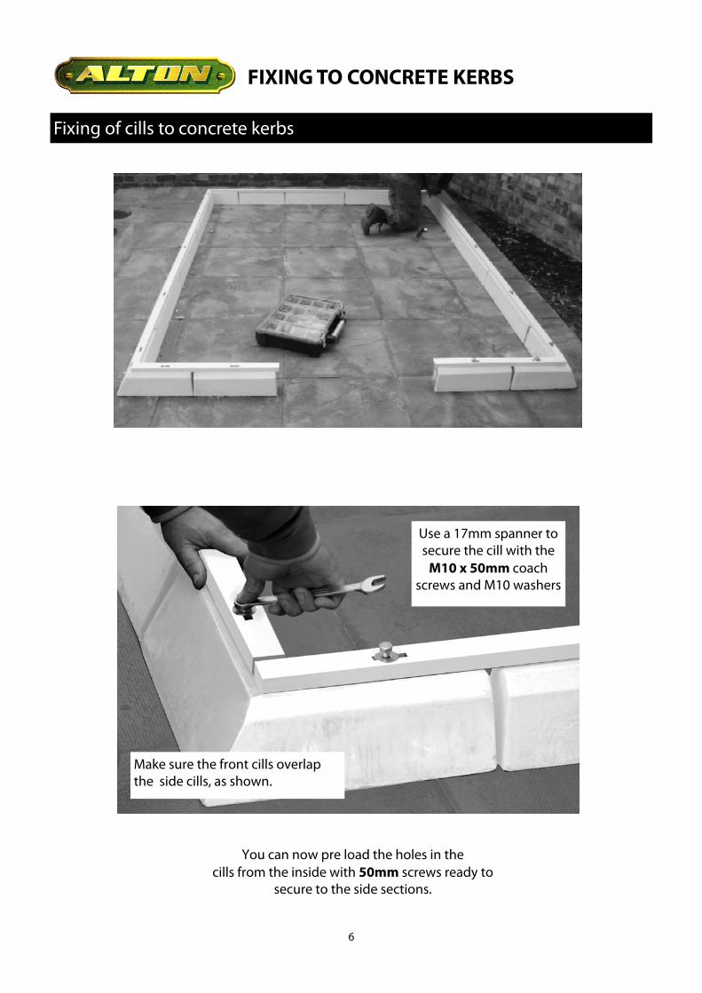
Fixing of cills to concrete kerbs
FIXING TO CONCRETE KERBS
Make sure the front cills overlap the side cills, as shown.
Use a 17mm spanner to secure the cill with the
M10 x 50mm coach screws and M10 washers
You can now pre load the holes in the cills from the inside with 50mm screws ready to
secure to the side sections.
7
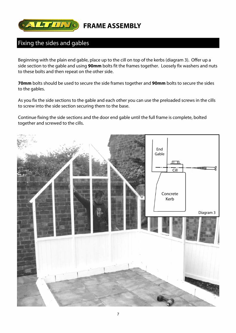
Fixing the sides and gables
FRAME ASSEMBLY
Beginning with the plain end gable, place up to the cill on top of the kerbs (diagram 3). Offer up a side section to the gable and using 90mm bolts fit the frames together. Loosely fix washers and nuts to these bolts and then repeat on the other side. 70mm bolts should be used to secure the side frames together and 90mm bolts to secure the sides to the gables. As you fix the side sections to the gable and each other you can use the preloaded screws in the cills to screw into the side section securing them to the base. Continue fixing the side sections and the door end gable until the full frame is complete, bolted together and screwed to the cills.
Diagram 3
Concrete Kerb
Cill
End Gable
8
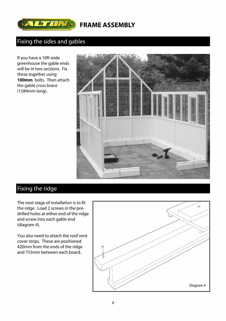
Fixing the sides and gables
FRAME ASSEMBLY
The next stage of installation is to fit the ridge. Load 2 screws in the pre-drilled holes at either end of the ridge and screw into each gable end (diagram 4). You also need to attach the roof vent cover strips. These are positioned 420mm from the ends of the ridge and 753mm between each board.
Fixing the ridge
Diagram 4
If you have a 10ft wide greenhouse the gable ends will be in two sections. Fix these together using 100mm bolts. Then attach the gable cross brace (1584mm long).

9
Fixing the ridge
FRAME ASSEMBLY
Diagram 5 Now run a bead of silicone along the top edge of the ridge to from a waterproof seal when the roof sections are fitted (diagram 5).
If you have a building longer than 13’ you will need to use the ridge extension bracket to join your ridge components (diagram 6). If you have a long building it may be necessary to prop the ridge up during instillation.
Diagram 6

10
Roof Assembly
FRAME ASSEMBLY
If you have an 8ft or 10ft wide greenhouse it is a good idea to fit the roof vents into the roof sections before you start fixing them in place. As the building is so tall it is very awkward to do this afterwards. Use 3 x 50mm screws per vent. It is also a good idea to fit the automatic openers at this stage. This will also hold the vent closed during fitting. Starting from the back of the greenhouse take the first roof section and offer it up to the ridge ensuring that it is pushed tightly against the top groove. With someone supporting this section push the 90mm bolts through the end section and into the roof section and loosely tighten. You should also screw through the roof section into the ridge using 60mm screws, you can only do this in a vent opening so use 2 screws per section. When this is complete continue with the remaining sections until the roof is complete. 70mm bolts are used to join roof sections together. 90mm bolts are used to join roof sections to the gables. NB: Remember you should use silicone between the roof sections and the ridge to create a good weather seal.
Fit roof vent before installation

11
Roof Assembly
FRAME ASSEMBLY
After assembling the roof you should fix the ridge brackets and eaves brackets into position. The ridge brackets fix directly into the ridge either side of the roof vent with a single 50mm screw. The eaves brackets fix at the join between the side section and the roof section with a single 25mm round head screw into each section. You should ensure that the side is straight and the overhang is equal before fixing.

12
Inserting the weather strips
FRAME ASSEMBLY
You should now fit the weather strips in the gaps between the panels. The shorter one fits in the side and the longer in the roof. Before inserting them double the end over, as shown below, to prevent the strip from sliding out.
Diagram 7

13
Installing eaves bracing
FRAME ASSEMBLY
Attach the metal eaves brace on the first frame section in from each end (375mm) and every other after that (750mm). Use 40mm round head screws.
Diagram 8

14
The majority of buildings will have a portal frame at 5ft intervals along the building. They are screwed into position with 50mm screws and the frame components bolt together using the 90mm bolts. Fix the side sway brace to the cill board (diagram 9), then fix it to the roof section (diagram 10) You may have to lift the ridge bar up to make it level before fixing the sway brace, you could either prop this up (if you haven’t already) or ask 2 helpers to push the side inwards. Then fix the horizontal top brace pushing this tight up to the side brace (diagram 11).
Fixing the portal frame
FRAME ASSEMBLY
Diagram 9
Diagram 11
Diagram 10

15
Fixing the portal frame
FRAME ASSEMBLY
Diagram 12 Finally bolt the middle brace to the sway brace and the top brace block. Screw the bottom of the middle brace to the sides (diagram 12).

16
Fixing end and ridge bracing
FRAME ASSEMBLY
Attach the end braces tight in the eaves with a 30mm wood screw, then fix brace at the other pre-drilled locations (diagram 13).
Diagram 13
Diagram 14
Also fix the ridge braces with 30mm screws. Use a small level to ensure these are installed correctly (diagram 14).

17
Finials, Cover Strips
The roof cover strips fix over the joint between the roof sections and the gable ends. They are screwed into position using three 30mm screws along the length of the component. Before screwing into position a bead of silicone should be applied along the internal groove to help ensure a waterproof seal is achieved. The finials are the decorative centrepiece of your greenhouse and screw on to the front and back gable ends with 50mm screws over the ridge end grain.
FINAL FIXING
18
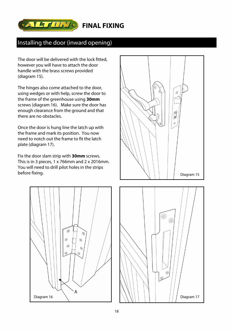
Installing the door (inward opening)
FINAL FIXING
Diagram 15
Diagram 16 Diagram 17
The door will be delivered with the lock fitted, however you will have to attach the door handle with the brass screws provided (diagram 15). The hinges also come attached to the door, using wedges or with help, screw the door to the frame of the greenhouse using 30mm screws (diagram 16). Make sure the door has enough clearance from the ground and that there are no obstacles. Once the door is hung line the latch up with the frame and mark its position. You now need to notch out the frame to fit the latch plate (diagram 17). Fix the door slam strip with 30mm screws. This is in 3 pieces, 1 x 766mm and 2 x 2016mm. You will need to drill pilot holes in the strips before fixing.
A

19
Installing rainwater kit
FINAL FIXING
Decide at which end the downpipes will be located. Use a length of string or a straight edge to give a fall of 12mm over every 3 meters. Fix the downpipe brackets into position with 19mm countersunk screws and slide the downpipe into the brackets and fix loosely with the bolt & nut (diagram 19). Drill a 5mm fixing hole in the stop end outlet, screw it into place with the downpipe connected, using a 19mm screw (diagram 18) Fix the support brackets (diagram 21) and joint bracket/s (diagram 20) as required for the length of greenhouse, use 19mm screws. Working from the downpipe end fix the guttering into the brackets having trimmed it to length if necessary with a fine saw. The stop end should finish level with the gable end of the greenhouse. Tighten up the downpipe and fix the shoe at the bottom (diagram 22). Repeat the process on the other side.
Diagram 18
Diagram 19
Diagram 20
Diagram 21
Diagram 22

20
OPTIONAL ACCESSORIES
The shelving can be installed on either side of the greenhouse. Start by installing the brackets for the shelving. Measure 335mm down from point ‘A’ (diagram 23) on each vertical side bar and place a mark. This gives you the location of the underside of the shelving. The small brackets go at each end of a run and the larger brackets are fixed at each intermediate frame section. Line the small brackets (point ‘B’, diagram 24) up with the marks you have made on the side frame of the greenhouse. Fix these with 19mm round head screws.
Installing high level shelf
A
B
Diagram 23
Diagram 24
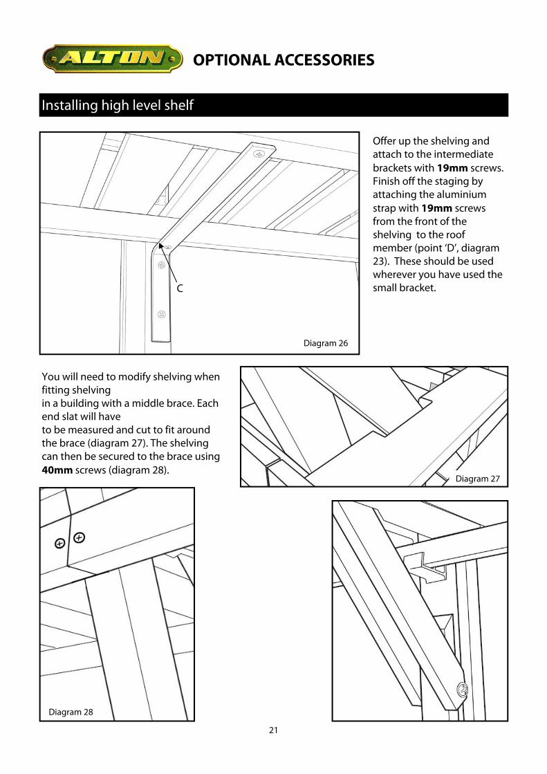
Line the larger intermediate brackets up with the mark you have made on the side frame (point ‘C’, diagram 26). Fix these brackets with 40mm screws. Where two pieces of shelving join two brackets will need to be used. A wooden splicing block will also need to be attached to the front bearers, use 30mm screws (diagram 25).
D
Diagram 25
21
Installing high level shelf
OPTIONAL ACCESSORIES
Diagram 26
C
Offer up the shelving and attach to the intermediate brackets with 19mm screws. Finish off the staging by attaching the aluminium strap with 19mm screws from the front of the shelving to the roof member (point ‘D’, diagram 23). These should be used wherever you have used the small bracket.
You will need to modify shelving when fitting shelving in a building with a middle brace. Each end slat will have to be measured and cut to fit around the brace (diagram 27). The shelving can then be secured to the brace using 40mm screws (diagram 28).
Diagram 27
Diagram 28

22
OPTIONAL ACCESSORIES
Staging
The Staging can also be installed on both side of the greenhouse. Start by measuring from the top of the cill board 720mm up the vertical frame sections and make a mark. This gives you the top edge of the brackets. The smaller single hole brackets go at each end of a run (diagram 29). The larger 2 hole brackets are used where 2 staging sections meet (diagram 30).
Offer up the staging and finish it off by installing the staging legs. Attach these to the next bearer in from the front (diagram 31) using 25mm round head screws. Attach the first two as close to the ends as possible, the rest should be lined up with every other glazing section there after (diagram 32).
Diagram 29
Diagram 30
Diagram 31
The smaller brackets are then used at the remaining intervals. Use 19mm round head screws to secure all of these brackets.

23
Staging
OPTIONAL ACCESSORIES
Diagram 33
Diagram 32
Where there is a portal frame you will need to measure and cut the spare slat and nail this in place. This will also cover the join between the two staging tops.

24
Alton Greenhouses, TGP Ltd, Blythe Park, Cresswell, Stoke-on-Trent, ST11 9RD
Telephone: 01782 385 409 www.Altongreenhouses.co.uk [email protected]