
Altivar Process ATV600, ATV900 NVE42416 06/2016 Altivar ...€¦ · Altivar Process ATV600, ATV900...
27
NVE42416.02 www.schneider-electric.com Altivar Process ATV600, ATV900 NVE42416 06/2016 Altivar Process ATV600, ATV900 Variable Speed Drives For Asynchronous and Synchronous motors ATEX manual for applications in explosive gas atmosphere or in the presence of combustible dust 06/2016
Transcript of Altivar Process ATV600, ATV900 NVE42416 06/2016 Altivar ...€¦ · Altivar Process ATV600, ATV900...
Altivar Process ATV600, ATV900
NVE42416 06/2016
NVE
4241
6.02
www.schneider-electric.com
Altivar Process ATV600, ATV900Variable Speed Drives For Asynchronous and Synchronous motors
ATEX manual for applications in explosive gas atmosphere or in the presence of combustible dust
06/2016

The information provided in this documentation contains general descriptions and/or technical character-istics of the performance of the products contained herein. This documentation is not intended as a substitute for and is not to be used for determining suitability or reliability of these products for specific user applications. It is the duty of any such user or integrator to perform the appropriate and complete risk analysis, evaluation and testing of the products with respect to the relevant specific application or use thereof. Neither Schneider Electric nor any of its affiliates or subsidiaries shall be responsible or liable for misuse of the information contained herein. If you have any suggestions for improvements or amendments or have found errors in this publication, please notify us. No part of this document may be reproduced in any form or by any means, electronic or mechanical, including photocopying, without express written permission of Schneider Electric.All pertinent state, regional, and local safety regulations must be observed when installing and using this product. For reasons of safety and to help ensure compliance with documented system data, only the manufacturer should perform repairs to components.When devices are used for applications with technical safety requirements, the relevant instructions must be followed. Failure to use Schneider Electric software or approved software with our hardware products may result in injury, harm, or improper operating results.Failure to observe this information can result in injury or equipment damage.© 2016 Schneider Electric. All rights reserved.
2 NVE42416 06/2016

Table of Contents
Safety Information. . . . . . . . . . . . . . . . . . . . . . . . . . . . . . . . . . . . . . . . . . . . 5About the Book . . . . . . . . . . . . . . . . . . . . . . . . . . . . . . . . . . . . . . . . . . . . . . 9
Chapter 1 Introduction . . . . . . . . . . . . . . . . . . . . . . . . . . . . . . . . . . . . . . . . . . . . . . . . . 13Functional Safety and ATEX applications . . . . . . . . . . . . . . . . . . . . . . . . . . . . . . . . . . . . . . . 13
Chapter 2 Applications for explosive atmosphere (ATEX) . . . . . . . . . . . . . . . . . . . . . 15ATEX zones. . . . . . . . . . . . . . . . . . . . . . . . . . . . . . . . . . . . . . . . . . . . . . . . . . . . . . . . . . . . . . 16ATEX Marking . . . . . . . . . . . . . . . . . . . . . . . . . . . . . . . . . . . . . . . . . . . . . . . . . . . . . . . . . . . . 17
Chapter 3 Wiring Diagrams For ATEX Applications . . . . . . . . . . . . . . . . . . . . . . . . . . 19General . . . . . . . . . . . . . . . . . . . . . . . . . . . . . . . . . . . . . . . . . . . . . . . . . . . . . . . . . . . . . . . . . 20ATEX Installation Case 1: Single drive with PTC and control unit. . . . . . . . . . . . . . . . . . . . . 21ATEX Installation Case 2: Single drive with PTC and control unit and with Safety Module Type Preventa XPS-AF . . . . . . . . . . . . . . . . . . . . . . . . . . . . . . . . . . . . . . . . . . . . . . . . . . . . . 22ATEX Installation Case 3: Drive Systems with PTC schematic 1 . . . . . . . . . . . . . . . . . . . . . 23ATEX Installation Case 4: Drive Systems with PTC schematic 2 . . . . . . . . . . . . . . . . . . . . . 24ATEX Installation Case 5: Drive Systems with PTC schematic 3 . . . . . . . . . . . . . . . . . . . . . 25ATEX Installation Case 6: Drive Systems with PTC schematic 4 . . . . . . . . . . . . . . . . . . . . . 26
NVE42416 06/2016 3

4 NVE42416 06/2016
Safety Information
Important Information
NOTICERead these instructions carefully, and look at the equipment to become familiar with the device before trying to install, operate, service, or maintain it. The following special messages may appear throughout this documentation or on the equipment to warn of potential hazards or to call attention to information that clarifies or simplifies a procedure.
PLEASE NOTEElectrical equipment should be installed, operated, serviced, and maintained only by qualified personnel. No responsibility is assumed by Schneider Electric for any consequences arising out of the use of this material.A qualified person is one who has skills and knowledge related to the construction and operation of electrical equipment and its installation, and has received safety training to recognize and avoid the hazards involved.
Qualification Of PersonnelOnly appropriately trained persons who are familiar with and understand the contents of this manual and all other pertinent product documentation are authorized to work on and with this product. In addition, these persons must have received safety training to recognize and avoid hazards involved. These persons must have sufficient technical training, knowledge and experience and be able to foresee and detect potential hazards that may be caused by using the product, by changing the settings and by the mechanical, electrical and electronic equipment of the entire system in which the product is used. All persons working on and with the product must be fully familiar with all applicable standards, directives, and accident prevention regulations when performing such work.
NVE42416 06/2016 5

Intended UseThis product is a drive for three-phase synchronous and asynchronous motors and intended for industrial use according to this manual.The product may only be used in compliance with all applicable safety standard and local regulations and directives, the specified requirements and the technical data. The product must be installed outside the hazardous ATEX zone. Prior to using the product, you must perform a risk assessment in view of the planned application. Based on the results, the appropriate safety measures must be implemented.Since the product is used as a component in an entire system, you must ensure the safety of persons by means of the design of this entire system (for example, machine design). Any use other than the use explicitly permitted is prohibited and can result in hazards. Electrical equipment should be installed, operated, serviced, and maintained only by qualified personnel.
Product Related InformationRead and understand these instructions before performing any procedure with this drive.
Drive systems may perform unexpected movements because of incorrect wiring, incorrect settings, incorrect data or other errors.
DANGERHAZARD OF ELECTRIC SHOCK, EXPLOSION OR ARC FLASH Only appropriately trained persons who are familiar with and understand the contents of this manual
and all other pertinent product documentation and who have received safety training to recognize and avoid hazards involved are authorized to work on and with this drive system. Installation, adjustment, repair and maintenance must be performed by qualified personnel.
The system integrator is responsible for compliance with all local and national electrical code requirements as well as all other applicable regulations with respect to grounding of all equipment.
Many components of the product, including the printed circuit boards, operate with mains voltage. Do not touch. Use only electrically insulated tools.
Do not touch unshielded components or terminals with voltage present. Motors can generate voltage when the shaft is rotated. Prior to performing any type of work on the
drive system, block the motor shaft to prevent rotation. AC voltage can couple voltage to unused conductors in the motor cable. Insulate both ends of unused
conductors of the motor cable. Do not short across the DC bus terminals or the DC bus capacitors or the braking resistor terminals. Before performing work on the drive system: Disconnect all power, including external control power that may be present. Place a Do Not Turn On label on all power switches. Lock all power switches in the open position. Wait 15 minutes to allow the DC bus capacitors to discharge. The DC bus LED is not an indicator
of the absence of DC bus voltage that can exceed 800 Vdc.Measure the voltage on the DC bus between the DC bus terminals (PA/+, PC/-) using a properly rated voltmeter to verify that the voltage is <42 Vdc
If the DC bus capacitors do not discharge properly, contact your local Schneider Electric represen-tative. Do not repair or operate the product.
Install and close all covers before applying voltage.Failure to follow these instructions will result in death or serious injury.
WARNINGUNANTICIPATED EQUIPMENT OPERATION Carefully install the wiring in accordance with the EMC requirements. Do not operate the product with unknown or unsuitable settings or data. Perform a comprehensive commissioning test.Failure to follow these instructions can result in death, serious injury, or equipment damage.
6 NVE42416 06/2016

Damaged products or accessories may cause electric shock or unanticipated equipment operation.
Contact your local Schneider Electric sales office if you detect any damage whatsoever.
(1) For USA: Additional information, refer to NEMA ICS 1.1 (latest edition), Safety Guidelines for the Application, Installation, and Maintenance of Solid State Control and to NEMA ICS 7.1 (latest edition), Safety Standards for Construction and Guide for Selection, Installation and Operation of Adjustable-Speed Drive Systems.
The temperature of the products described in this manual may exceed 80 °C (176 °F) during operation.
This equipment has been designed to operate outside of any hazardous location. Only install this equipment in zones known to be free of a hazardous atmosphere.
DANGERELECTRIC SHOCK OR UNANTICIPATED EQUIPMENT OPERATIONDo not use damaged products or accessories.Failure to follow these instructions will result in death or serious injury.
WARNINGLOSS OF CONTROL The designer of any control scheme must consider the potential failure modes of control paths and,
for critical control functions, provide a means to achieve a safe state during and after a path failure. Examples of critical control functions are emergency stop, overtravel stop, power outage and restart.
Separate or redundant control paths must be provided for critical control functions. System control paths may include communication links. Consideration must be given to the
implications of unanticipated transmission delays or failures of the link. Observe all accident prevention regulations and local safety guidelines (1). Each implementation of the product must be individually and thoroughly tested for proper operation
before being placed into service.Failure to follow these instructions can result in death, serious injury, or equipment damage.
NOTICEDESTRUCTION DUE TO INCORRECT MAINS VOLTAGEBefore switching on and configuring the product, verify that it is approved for the mains voltageFailure to follow these instructions can result in equipment damage.
WARNINGHOT SURFACES Ensure that any contact with hot surfaces is avoided. Do not allow flammable or heat-sensitive parts in the immediate vicinity of hot surfaces. Verify that the product has sufficiently cooled down before handling it. Verify that the heat dissipation is sufficient by performing a test run under maximum load conditions.Failure to follow these instructions can result in death, serious injury, or equipment damage.
DANGERPOTENTIAL FOR EXPLOSIONInstall and use this equipment in non-hazardous locations only.Failure to follow these instructions will result in death or serious injury.
NVE42416 06/2016 7

8 NVE42416 06/2016

About the Book
At a Glance
Document ScopeThe purpose of this document is to explain how the STO (Safe Torque Off) safety function allows the ATV630, 650, 660 & 680, ATV930, 950, 960 & 980 variable speed drives to control and command motors installed in explosive atmospheres (ATEX)
Validity NoteOriginal instructions and information given in this manual have been written in English (before optional translation).This documentation is valid for the Altivar Process drives described in the Installation manual.The technical characteristics of the devices described in this document also appear online. To access this information online:
The characteristics that are presented in this manual should be the same as those characteristics that appear online. In line with our policy of constant improvement, we may revise content over time to improve clarity and accuracy. If you see a difference between the manual and online information, use the online information as your reference.
Related DocumentsUse your tablet or your PC to quickly access detailed and comprehensive information on all our products on www.schneider-electric.comThe internet site provides the information you need for products and solutions The whole catalog for detailed characteristics and selection guides The CAD files to help design your installation, available in over 20 different file formats All software and firmware to maintain your installation up to date A large quantity of White Papers, Environment documents, Application solutions, Specifications... to
gain a better understanding of our electrical systems and equipment or automation And finally all the User Guides related to your drive, listed below:
Step Action1 Go to the Schneider Electric home page www.schneider-electric.com.2 In the Search box type the reference of a product or the name of a product range.
Do not include blank spaces in the reference or product range. To get information on grouping similar modules, use asterisks (*).
3 If you entered a reference, go to the Product Datasheets search results and click on the reference that interests you.If you entered the name of a product range, go to the Product Ranges search results and click on the product range that interests you.
4 If more than one reference appears in the Products search results, click on the reference that interests you.
5 Depending on the size of your screen, you may need to scroll down to see the data sheet.6 To save or print a data sheet as a .pdf file, click Download XXX product datasheet.
Title of Documentation Reference NumberATV600 Getting Started EAV63253 (English), EAV63254 (French),
EAV63255 (German), EAV63256 (Spanish), EAV64310 (Italian), EAV64298 (Chinese)
ATV600 Getting Started Annex (SCCR) EAV64300 (English)ATV630, ATV650 Installation Manual EAV64301 (English), EAV64302 (French),
EAV64306 (German), EAV64307 (Spanish), EAV63257 (Italian), EAV64317 (Chinese)
NVE42416 06/2016 9

You can download these technical publications and other technical information from our website at http://download.schneider-electric.com
ATV630, ATV650 Programming Manual EAV64318 (English), EAV64320 (French), EAV64321 (German), EAV64322 (Spanish), EAV64323 (Italian), EAV64324 (Chinese)
ATV600 Modbus Serial Link Manual (Embedded) EAV64325 (English)ATV600 Ethernet Manual (Embedded) EAV64327 (English)ATV600 Ethernet IP - Modbus TCP Manual (VW3A3720) EAV64328 (English)ATV600 PROFIBUS DP manual (VW3A3607) EAV64329 (English)ATV600 DeviceNet manual (VW3A3609) EAV64330 (English)ATV600 PROFINET manual (VW3A3627) EAV64331 (English)ATV600 CANopen Serial Link Manual (VW3A3608, 618, 628) EAV64333 (English)ATV600 Communication Parameters EAV64332 (English)ATV600 Safety Function manual EAV64334 (English)Drive Systems – Installation manual NHA37119 (English), NHA37121 (French),
NHA37118 (German), NHA37122 (Spanish), NHA37123 (Italian), NHA37130 (Chinese), NHA37124 (Dutch), NHA37126 (Polish), NHA37127 (Portuguese), NHA37128 (Russian), NHA37129 (Turkish)
ATV660 Handbook NHA37111 (English), NHA37110 (German)ATV680 Handbook NHA37113 (English), NHA37112 (German)ATV900 Getting Started NHA61578 (English), NHA61579 (French),
NHA61580 (German), NHA61581 (Spanish), EAV61724 (Italian), NHA61583 (Chinese)
ATV900 Getting Started Annex (SCCR) NHA61584 (English)ATV930, ATV950 Installation Manual NHA80932 (English), NHA80933 (French),
NHA80934 (German), NHA80935 (Spanish), NHA80936 (Italian), NHA80937 (Chinese)
ATV930, ATV950, ATV960, ATV980 Programming Manual NHA80757 (English), NHA80758 (French), NHA80759 (German), NHA80760 (Spanish), NHA80761 (Italian), NHA80762 (Chinese)
ATV900 Modbus SL manual (Embedded) NHA80939 (English)ATV900 Ethernet manual (Embedded) NHA80940 (English)ATV900 PROFIBUS DP manual (VW3A3607) NHA80941 (English)ATV900 DeviceNet manual (VW3A3609) NHA80942 (English)ATV900 PROFINET manual (VW3A3627) NHA80943 (English)ATV900 CANopen manual (VW3A3608, 618, 628) NHA80945 (English)ATV900 EtherCAT manual - (VW3A3601) NHA80946 (English)ATV900 Communication Parameters NHA80944 (English)ATV900 Service Instructions NHA80954 (English)ATV900 Safety Functions manual NHA80947 (English), NHA80948 (French),
NHA80949 (German), NHA80950 (Spanish), NHA80951 (Italian), NHA80953 (Chinese)
Drive Systems – Installation manual NHA37118 (German), NHA37119 (English), NHA37121 (French), NHA37122 (Spanish), NHA37123 (Italian), NHA37124 (Dutch), NHA37126 (Polish), NHA37127 (Portuguese), NHA37128 (Russian), NHA37129 (Turkish), NHA37130 (Chinese)
ATV960 Configuration guide NHA37115 (English), NHA37114(German)ATV980 Configuration guide NHA37117 (English), NHA37116(German)
Title of Documentation Reference Number
10 NVE42416 06/2016

TerminologyThe technical terms, terminology, and the corresponding descriptions in this manual normally use the terms or definitions in the relevant standards.In the area of drive systems this includes, but is not limited to, terms such as error, error message, failure, fault, fault reset, protection, safe state, safety function, warning, warning message, and so on.Among others, these standards include: IEC 61800 series: Adjustable speed electrical power drive systems IEC 61508 Ed 1 & 2: Functional safety of electrical/electronic/programmable electronic safety-related EN ISO 13849-1 & 2 Safety of machinery - Safety related parts of control systems. IEC 61158 series: Industrial communication networks - Fieldbus specifications IEC 61784 series: Industrial communication networks - Profiles IEC 60204-1: Safety of machinery - Electrical equipment of machines – Part 1: General requirementsIn addition, the term zone of operation is used in conjunction with the description of specific hazards, and is defined as it is for a hazard zone or danger zone in the EC Machinery Directive (2006/42/EC) and in ISO 12100-1.
EC Declaration of ConformityThe EC Declaration of Conformity can be obtained on www.schneider-electric.com
Certification for functional safetyThe integrated safety function is compatible and certified following IEC 61800-5-2 Ed.1 Adjustable speed electrical power drive systems – Part 5-2 : Safety requirements – FunctionalIEC 61800-5-2 as a product standard, sets out safety-related considerations of Power Drive Systems Safety Related PDS (SR) s in terms of the framework of IEC 61508.Compliance with IEC 61800-5-2 standard, for the following described safety function, will facilitate the incorporation of a PDS(SR) (Power Drive System with safety-related functions) into a safety-related control system using the principles of IEC 61508, IEC 60204-1, IEC 62061 and ISO 13849-1 & ISO 13849-2 for process-systems and machinery. The defined safety function is SIL 3 capability in compliance with IEC 61800-5-2 and IEC 61508 series Performance Level PL e in compliance with ISO 13849-1 Category 3 in compliance with European standard ISO 13849-1Also refer to the Safety function capability section in the ATV600 Safety Function manual EAV64334.The safety demand mode of operation is considered in high demand or continuous mode of operation according to the IEC 61800-5-2 standard.The certificate for functional safety is accessible on www.schneider-electric.com
NVE42416 06/2016 11

12 NVE42416 06/2016

Altivar Process ATV600, ATV900
NVE42416 06/2016
Introduction
Chapter 1Introduction
Functional Safety and ATEX applications
GeneralThe variable speed drive ATV630, 650, 660 & 680, ATV930, 950, 960 & 980 integrates the STO (Safe Torque Off) safety function which shuts off the motor torque safely. The use of the STO safety function allows the drive to be installed as a part of the safety-related electrical, electronic and programmable electronic control systems, dedicated to the safety of a machine or an industrial process.The integrated safety function is compatible and certified following the information given in the Certification for Functional Safety section (see page 11). It complies also with the EN 50495 (2010): Safety devices required for the safe functioning of equipment with respect to explosion risks.The use of the STO safety function is required for the variable speed drive ATV630, 650, 660 & 680, ATV930, 950, 960 & 980 to control and command motors installed in explosive atmospheres (ATEX).The STO safety function is an ATEX certified function, according ATEX 94/9/EC directive and forthcoming 2014/34/EU directive.
Monitoring Of the ATEX MotorThe STO input(s) is (are) connected to the switching system which is embedded in the thermal sensor of the ATEX motor (or connected to the switching system of the control system if ATEX sensors of PTC type are used).The variable speed drive ATV630, 650, 660 & 680, ATV930, 950, 960 & 980 intended to be used to command and control asynchronous motors shall be installed only outside potentially explosive atmospheres for the protection of explosion-protected motors.
NVE42416 06/2016 13

14 NVE42416 06/2016

Altivar Process ATV600, ATV900
NVE42416 06/2016
Applications for explosive atmosphere (ATEX)
Chapter 2Applications for explosive atmosphere (ATEX)
What Is in This Chapter?This chapter contains the following topics:
Topic PageATEX zones 16ATEX Marking 17
NVE42416 06/2016 15

ATEX zones
ClassificationThe European directive 1999/92/EC (also called ATEX 137, or directive for protection of workers) classifies the ATEX zones and the type of products that they are compatible with. The user should define the ATEX zone in which the ATEX motor will be installed.This equipment has been designed to operate outside of any hazardous location. Only install this equipment in zones known to be free of a hazardous atmosphere.Different wiring diagrams for installation are suggested in this document. They are compatible with the use of motors in ATEX zones 1/21 or 2/22The following table summarizes characteristics related to each ATEX zone
NOTE: Neither electrical equipment nor motors can be installed in ATEX zone 0 or 20.
GeneralThe European directive 94/9/EC and forthcoming 2014/34/UE (also called ATEX 95, or product directive) defines applicable requirements for ATEX products and requirements for procedure of certification.OEMs, installers, users are responsible for the choice and the commissioning of the products they use in order to realize the ATEX protection of systems that they design or systems that they implement. The motor needs to be ATEX certified EX “d” and compatible for use in zone 1/21 or 2/22. The motor shall be equipped with thermal sensor(s) with embedded switching system ATEX certified,
or shall be equipped with thermal sensor(s) ATEX certified, associated to a control unit (Level of protection intrinsic safety "i"), which is to be also ATEX certified.
NOTE: Usually, the control unit is designed to be used outside the hazardous ATEX zone. Then it is possible to install the control unit near the variable speed drive, outside the hazardous ATEX zone.The switching system, embedded into the thermal sensor, or included into the control unit of the thermal protection of the ATEX motor, shall be connected to the STO input of the variable speed drive ATV630, 650, 660 & 680, ATV930, 950, 960 & 980. When the excessive temperature of the ATEX motor is reached, the control system triggers the STO safety function. The electrical power of the motor is removed to help to ensure a temperature of the motor frame below the maximum temperature depending on the gas or the dust atmosphere in which the ATEX motor is installed.When the ATEX application needs to apply the STO safety function, and prevent automatic restart, then a safety module (type Preventa) is to be used. The suggested wiring diagrams describe how the switching system, embedded into the thermal sensor or included into the control unit, is connected to the safety module. The output of the safety module must be connected to the STO input of the variable speed drive ATV630, 650, 660 & 680, ATV930, 950, 960 & 980.
Atmosphere Zone Definition Presence of explosive atmosphere per year
Gas 0 Explosive atmosphere is present continuously, for long periods or frequently due to malfunctions
> 1000 hDust 20Gas 1 Explosive atmosphere is likely to occur due to expected malfunctions 10...1000 hDust 21Gas 2 Explosive atmosphere is unlikely to occur or, if occurring, is likely to only be
of short duration and not in normal duty< 10 h
Dust 22
16 NVE42416 06/2016
ATEX Marking
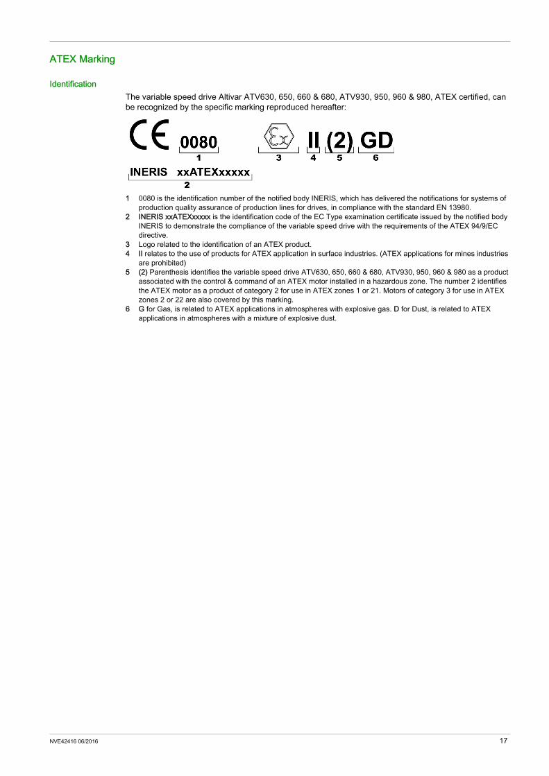
IdentificationThe variable speed drive Altivar ATV630, 650, 660 & 680, ATV930, 950, 960 & 980, ATEX certified, can be recognized by the specific marking reproduced hereafter:
1 0080 is the identification number of the notified body INERIS, which has delivered the notifications for systems of production quality assurance of production lines for drives, in compliance with the standard EN 13980.
2 INERIS xxATEXxxxxx is the identification code of the EC Type examination certificate issued by the notified body INERIS to demonstrate the compliance of the variable speed drive with the requirements of the ATEX 94/9/EC directive.
3 Logo related to the identification of an ATEX product.4 II relates to the use of products for ATEX application in surface industries. (ATEX applications for mines industries
are prohibited)5 (2) Parenthesis identifies the variable speed drive ATV630, 650, 660 & 680, ATV930, 950, 960 & 980 as a product
associated with the control & command of an ATEX motor installed in a hazardous zone. The number 2 identifies the ATEX motor as a product of category 2 for use in ATEX zones 1 or 21. Motors of category 3 for use in ATEX zones 2 or 22 are also covered by this marking.
6 G for Gas, is related to ATEX applications in atmospheres with explosive gas. D for Dust, is related to ATEX applications in atmospheres with a mixture of explosive dust.
NVE42416 06/2016 17

18 NVE42416 06/2016

Altivar Process ATV600, ATV900
NVE42416 06/2016
Wiring Diagrams For ATEX Applications
Chapter 3Wiring Diagrams For ATEX Applications
What Is in This Chapter?This chapter contains the following topics:
Topic PageGeneral 20ATEX Installation Case 1: Single drive with PTC and control unit 21ATEX Installation Case 2: Single drive with PTC and control unit and with Safety Module Type Preventa XPS-AF
22
ATEX Installation Case 3: Drive Systems with PTC schematic 1 23ATEX Installation Case 4: Drive Systems with PTC schematic 2 24ATEX Installation Case 5: Drive Systems with PTC schematic 3 25ATEX Installation Case 6: Drive Systems with PTC schematic 4 26
NVE42416 06/2016 19

General
RequirementsRequirements provided by the ATEX standards for installation should be fulfilled. Also follow the requirements below: IEC 60079-14 Electrical installations design, selection and erection, for applications in atmospheres
with explosive gas, local regulation, cabling rules for applications in atmospheres with presence of gas or dust.
Wiring Diagrams PresentationSchemes suggested in this document for installation and commissioning of variable speed drives ATV630, 650, 660 & 680, ATV930, 950, 960 & 980 for ATEX applications are based on thermal sensors (for example a PTC sensor) embedded in the ATEX motor and an intrinsic safety "i" control unit. The control unit is a device which converts in a switching function the variation of the characteristic of a thermal sensor.
ATEX Periodic testThe complete functional safety loop (which starts from the ATEX motor thermal sensor up to the STO safety function embedded in the drive), shall be activated at least once a year for preventive maintenance purposes, in order to check that the electrical power is always automatically removed from the motor in case of excessive temperature.
Shielded Cables on I/O
WARNINGUNEXPECTED EQUIPMENT OPERATION Use shielded cables for all digital and analog I/O and communication signals Ground cable shields at a single point. Route communication and I/O cables separately from power cables.Failure to follow these instructions can result in death, serious injury, or equipment damage.
20 NVE42416 06/2016

ATEX Installation Case 1: Single drive with PTC and control unit
Description ATEX motor in Zone 1 or 21 or 2 or 22 STO inputs used for protection of the ATEX motor sensor only, SIL1 capability according to IEC 61508,
stop category 0 according to IEC 60204-1without protection against supply interruption or voltage reduction and subsequent rotation.
Thermal protection of the ATEX motor by using an ATEX thermal sensor (PTC type, without embedded switching system), and a control unit for the PTC conversion, including the switching system.
Wiring Diagram
(1) ATEX Zone 1 or 21 or 2 or 22 with at least 1 thermal sensor PTC type(2) ATEX certified Control unit conversion / insulation / switching system with Level of protection intrinsic safety "i".(K72) ATEX certified PTC relay
NVE42416 06/2016 21
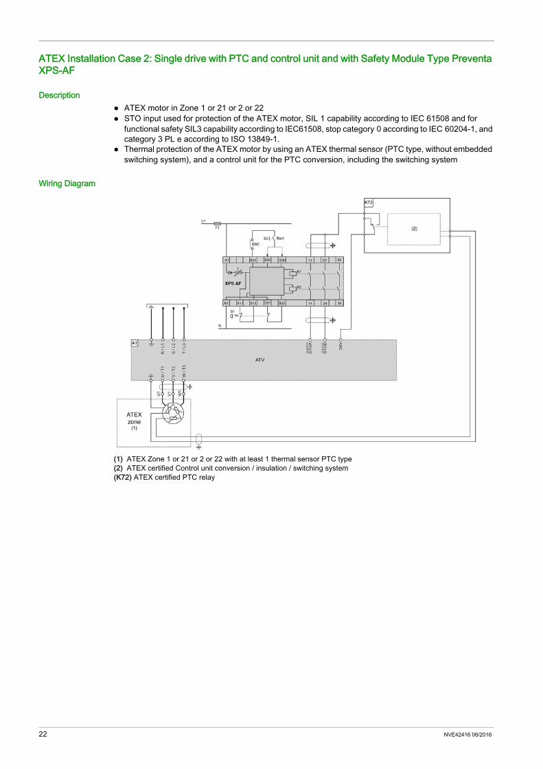
ATEX Installation Case 2: Single drive with PTC and control unit and with Safety Module Type Preventa XPS-AF
Description ATEX motor in Zone 1 or 21 or 2 or 22 STO input used for protection of the ATEX motor, SIL 1 capability according to IEC 61508 and for
functional safety SIL3 capability according to IEC61508, stop category 0 according to IEC 60204-1, and category 3 PL e according to ISO 13849-1.
Thermal protection of the ATEX motor by using an ATEX thermal sensor (PTC type, without embedded switching system), and a control unit for the PTC conversion, including the switching system
Wiring Diagram
(1) ATEX Zone 1 or 21 or 2 or 22 with at least 1 thermal sensor PTC type(2) ATEX certified Control unit conversion / insulation / switching system(K72) ATEX certified PTC relay
22 NVE42416 06/2016
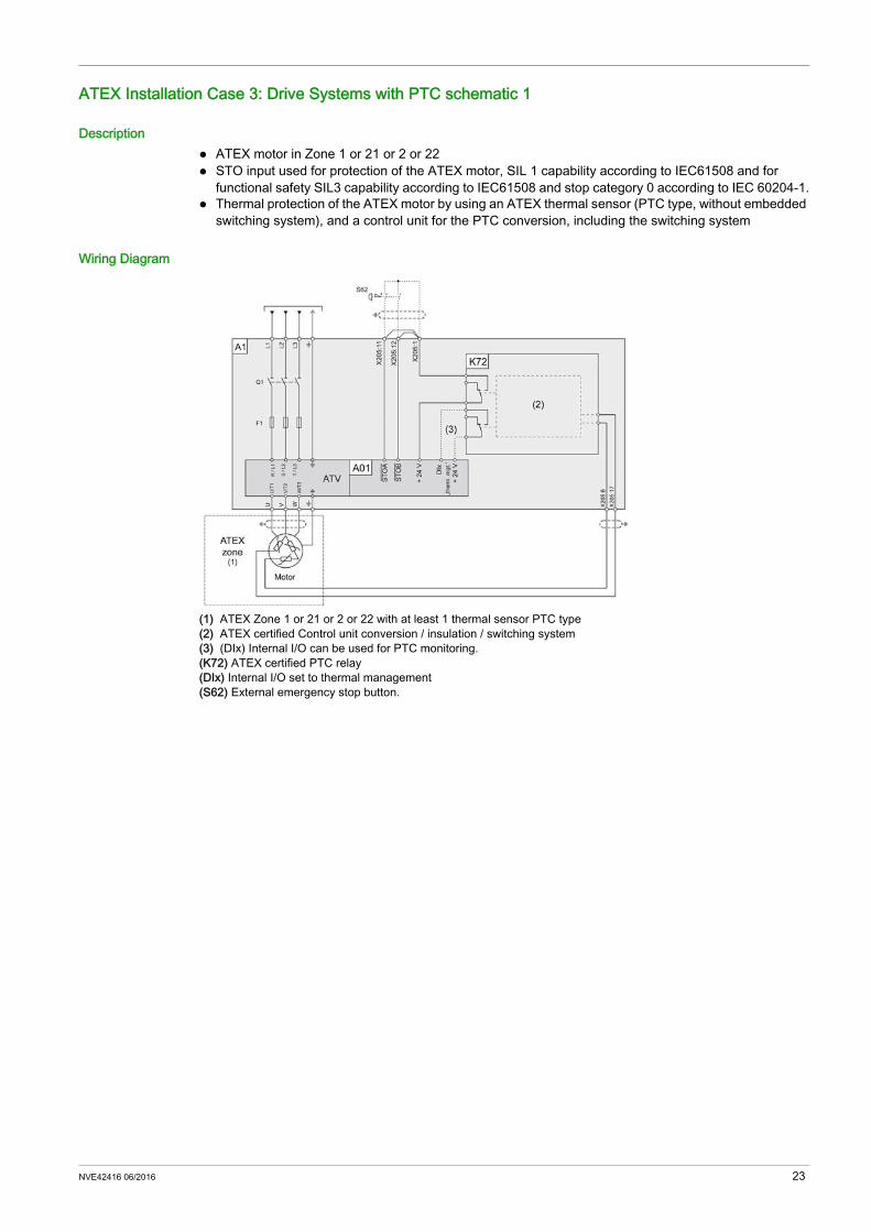
ATEX Installation Case 3: Drive Systems with PTC schematic 1
Description ATEX motor in Zone 1 or 21 or 2 or 22 STO input used for protection of the ATEX motor, SIL 1 capability according to IEC61508 and for
functional safety SIL3 capability according to IEC61508 and stop category 0 according to IEC 60204-1. Thermal protection of the ATEX motor by using an ATEX thermal sensor (PTC type, without embedded
switching system), and a control unit for the PTC conversion, including the switching system
Wiring Diagram
(1) ATEX Zone 1 or 21 or 2 or 22 with at least 1 thermal sensor PTC type(2) ATEX certified Control unit conversion / insulation / switching system(3) (DIx) Internal I/O can be used for PTC monitoring.(K72) ATEX certified PTC relay(DIx) Internal I/O set to thermal management(S62) External emergency stop button.
NVE42416 06/2016 23

ATEX Installation Case 4: Drive Systems with PTC schematic 2
Description ATEX motor in Zone 1 or 21 or 2 or 22 STO input used for protection of the ATEX motor, SIL 1 capability according to IEC61508 and for
functional safety SIL3 capability according to IEC61508 and stop category 0 according to IEC 60204-1. Thermal protection of the ATEX motor by using an ATEX thermal sensor (PTC type, without embedded
switching system), and a control unit for the PTC conversion, including the switching system
Wiring Diagram
(1) ATEX Zone 1 or 21 or 2 or 22 with at least 1 thermal sensor PTC type(2) ATEX certified Control unit conversion / insulation / switching system(K72) ATEX certified PTC relay(DIx) Internal I/O set to thermal management(Kx) Optional additional contacts within the safety path(S61) Emergency Stop button mounted in the enclosure door.(S62) External emergency stop button.
24 NVE42416 06/2016

ATEX Installation Case 5: Drive Systems with PTC schematic 3
Description ATEX motor in Zone 1 or 21 or 2 or 22 STO input used for protection of the ATEX motor, SIL 1 capability according to IEC61508 and for
functional safety SIL3 capability according to IEC61508, stop category 1 according to IEC 60204-1 and category 3 PL e according to ISO 13849-1.
Thermal protection of the ATEX motor by using an ATEX thermal sensor (PTC type, without embedded switching system), and a control unit for the PTC conversion, including the switching system
Wiring Diagram
(1) ATEX Zone 1 or 21 or 2 or 22 with at least 1 thermal sensor PTC type(2) ATEX certified Control unit conversion / insulation / switching system(K72) ATEX certified PTC relay(DIx) Internal I/O set to thermal management(DIy) Internal I/O set to fast stop(Kx) Optional additional contacts within the safety path(K61) Safety relay for monitoring the Emergency Stop circuit Preventa XPS-ATR(S61) Emergency Stop button mounted in the enclosure door(S62) External emergency stop button(S63) Manual reset button
NVE42416 06/2016 25

ATEX Installation Case 6: Drive Systems with PTC schematic 4
Description ATEX motor in Zone 1 or 21 or 2 or 22 STO input used for protection of the ATEX motor and for the functional safety of Category 3 (ISO 13849-
1) and for SIL 1 (IEC/EN 61508 or IEC/EN 61800-5-2) in stopping category 0 according to IEC/EN 60204-1,
Thermal protection of the ATEX motor by using an ATEX thermal sensor (PTC type, without embedded switching system), and a control unit for the PTC conversion, including the switching system
Embedded switching system protected against the failures of the installation.
Wiring Diagram
(1) ATEX Zone 1 or 21 or 2 or 22 with at least 1 thermal sensor PTC type(2) ATEX certified Control unit conversion / insulation / switching system(K72) ATEX certified PTC relay(DIx) Internal I/O set to thermal management(Kx) Optional additional contacts within the safety path(S61) Emergency Stop button mounted in the enclosure door.(S62) External emergency stop button.
26 NVE42416 06/2016

ATV600_900_ATEX_manual_NVE42416_02
06/2016


