Altivar AFE Configuration fuide for 120860 kW Altivar AFE Drive Systems 1 Active Front End Altivar...
100
Altivar AFE Configuration guide for 120...860 kW 04/2010
Transcript of Altivar AFE Configuration fuide for 120860 kW Altivar AFE Drive Systems 1 Active Front End Altivar...

Altivar AFE
Configuration guide for 120...860 kW
04/2010

General remarks
The following symbols should assist you in handling the instructions:
Advice, tip !
General information, note exactly !
The requirements for successful commissioning are correct selection of the device, proper planning and installation. If you have
any further questions, please contact the supplier of the device.
Capacitor discharge !
Before performing any work on or in the device, disconnect it from the mains and wait at least 15 minutes until the capacitors have
been fully discharged to ensure that there is no voltage on the device.
Automatic restart !
With certain parameter settings it may happen that the Active Front End restarts automatically when the mains supply returns after
a power failure. Make sure that in this case neither persons nor equipment is in danger.
Commissioning and service !
Work on or in the device must be done only by duly qualified staff and in full compliance with the appropriate instructions and
pertinent regulations. In case of a fault contacts which are normally potential-free and/or PCBs may carry dangerous voltages. To
avoid any risk to humans, obey the regulations concerning "Work on Live Equipment" explicitly.
Terms of delivery
The latest edition "General Terms of Delivery of the Austrian Electrical and Electronics Industry Association" form the basis of our
deliveries and services.
Specifications in this document
We are always anxious to improve our products and adapt them to the latest state of the art. Therefore, we reserve the right to
modify the specifications given in this document at any time, particular those referring to weights and dimensions. All planning
recommendations and connection examples are non-binding suggestions for which we cannot assume liability, particularly
because the regulations to be complied depend on the type and place of installation and on the use of the devices.
All foreign-language translations result from the German or English version. Please consider those in case of unclarity.
Basis of contract
The specifications in text and drawings of this document are no subject of contract in the legal sense without explicit confirmation.
Regulations
The user is responsible to ensure that the device and its components are used in compliance with the applicable regulations. It is
not permitted to use these devices in residential environments without special measures to suppress radio frequency
interferences.
Trademark rights
Please note that we do not guarantee that the connections, devices and processes described herein are free from patent or
trademark rights of third parties.
Copyright
Layout, equipment, logos, texts, diagrams and pictures of this document are copyrighted. All rights are reserved.

Content Altivar AFE Drive Systems
1
Active Front End Altivar AFE
Configuration guide for 120...860 kW
Content
Drive Systems
Drive Systems.............................................................................1 Overview .................................................................................................3
General specification..................................................................9 Basic concept .........................................................................................9 Quality ...................................................................................................12 Special safety notes..............................................................................16 Mains conditions...................................................................................17
Low harmonic drive / 4-quadrant single drive .........................21 Specification .........................................................................................21 Wiring diagram......................................................................................24
Common DC bus......................................................................35 Specification .........................................................................................35 Examples for calculation.......................................................................37 Wiring diagram......................................................................................39
Active Front End units parallel..................................................50 Specification .........................................................................................50 Examples for calculation.......................................................................54 Wiring diagram......................................................................................55
Technical data ..........................................................................65 Active Front End AFE............................................................................65 Line filter module LFM ..........................................................................66 Line filter choke LFC.............................................................................69 Active Infeed Converter AIC .................................................................72 Fuses and cable cross sections ...........................................................79 Cubicle installation................................................................................83
Options .....................................................................................86 Overview ...............................................................................................86 Control options .....................................................................................88 Options depending on the power.........................................................90
Inverter......................................................................................92 Data for the DC bus ..............................................................................92 Parameter settings................................................................................95

Content Altivar AFE Drive Systems
2

Overview Altivar AFE
3
Overview
Product Active Front End AFE
Brief description The Active Front End is used to reduce the mains current harmonics as well as to return excess energy
to the mains. Consequently it is possible to save energy by reducing the share of reactive power and the
costs can be reduced because the accumulating energy is returned to the mains.
Power range 120...860 kW
Voltage ranges 3 AC 380…480 V (120...675 kW)
3 AC 480 V (120...675 kW)
3 AC 500...690 V (145...860 kW)
Mains frequency 50 / 60 Hz5 %
Interfaces Removable operating panel, control terminals can be extended,
fieldbus connection via Modbus or CANopen
Protection degree Built-in units IP00
Components Active Infeed Converter AIC
Line Filter Module LFM
Line Filter Choke LFC
Further reading This catalogue contains all information about project planning and order of the Active Front End.
Further information about mounting are given in the mounting instructions and information about
parameterization in the Description of functions.

Overview Altivar AFE
4
The Active Front End allows energy regeneration
The Active Front End is an option for the frequency inverter to return
energy to the mains.
It provides 4-quadrant operation and thus it is well qualified for all
applications with generator operating mode.
60%
Special features
The Active Front End is a supply and regeneration
unit that provides a constant DC voltage supply
independent of the load situation. At this DC bus
one or several inverters can be operated. In this
way up to four Active Front End units can be
connected to this DC bar in parallel in order to
improve the redundancy and to increase the total
power.
Mains interferences / mains conditions
■ Power factor cos Phi 1 independent of the load
situation and the energy direction
■ No converter transformer required
■ Mains voltage drops up to 40 %
without interruption of operation
■ Wide mains frequency range permitted
■ Adjustable regenerating power
e.g. for operation with diesel generator
■ Mains short circuit power up to 100 kA permitted
Simple planning and installation
■ Line contactor already integrated
■ No external control voltage supply necessary
■ Integrated charging circuit for max. fourfold
power at the DC bus
■ Operation independent of the phase sequence
■ Optimised administration of spare parts due to
equal components in the Active Infeed Converter
and the inverter
Energy-saving operation
■ Energy regeneration to the supplying mains
■ Improved efficiency due to innovative control
system
■ No damping resistors with heavy losses required
and thus it is especially robust in respect of
heavily distorted mains voltages.
Typical applications
Crane applications (hoists, long-travels, …)
Downhill conveyors, winches, escalators
Complex drive systems
Test benches and high dynamic drives
Pump / turbine combinations

Overview Altivar AFE
5
Applications
The Active Front End is equipped with numerous
integrated functions and thus it meets the
sophisticated demands in industry, machine
building and automation. The design allows the simple use in combination
with an inverter as well as building up a common
DC bus for a multitude of drives.
The Active Front End is connected upstream to the
standard frequency inverter and consists of three
components: ■ Active Infeed Converter
■ Line Filter Module (EMC filter, line contactor and
charging circuit)
■ Line Filter Choke (3 parts)
Single drive Common DC bus Active Font End units parallel
M
ActiveFrontEnd
Inverter
Mains
DC link
M M M
Mains
DC bus
ActiveFrontEnd
Inverter Inverter Inverter
M M M
Mains
ActiveFrontEnd
ActiveFrontEnd
DC bus
InverterInverterInverter
When adding an Active Front
End to a standard drive the
arising energy (e.g. when
lowering a load) is returned
to the mains.
The supply via a common DC bus is often a
perfect solution for group drives (e.g. at sheet
metal processing machines, roller conveyors or
test benches). In this case the total power of the
inverters can be fourfold higher than the nominal
power of the Active Front End.
The parallel connection of up to four Active
Front End units is used to increase the safety by
redundancy and furthermore it enables increase
of power or the use of smaller Active Front End
units.
General technical data Voltage / frequency
380...400 V / 440 V / 480 V ±10 %:
500...525 V ±10 %:
575...600 V / 690 V ±10 %:
50/60 Hz ±5 % (30...70 Hz for short periods)
50 Hz ±5 %
50/60 Hz ±5 % (30...70 Hz for short periods) Overvoltage class Category III Power range 120...860 kW Overload +20 % for 60 seconds per 10 minutes Operating temperature -10...+45 °C (+60 °C with derating) Protection degree IP00 Control concept Controllable via terminals, CANopen bus or Modbus built-in Approvals CE, in preparation: UL, CSA
AFE-type 400V 120 145 175 240 275 340 430 540 675 AFE input current in A 177 212 255 348 395 495 628 780 980
DC power (400 V) in kW 120 143 172 238 268 336 425 530 665
AFE-type 480V 120 145 175 240-13 275 340 430-15 540-15 675 AFE input current in A 160 200 200 348 395 495 628 780 980
DC power (480 V) in kW 130 162 162 277 315 390 490 610 770
AFE-type 690V 145 175 220 275 340 430 540 675 860 AFE input current in A 120 150 185 (160)1) 228 285 360 450 563 715
DC power (500 V) in kW 102 127 157 193 242 305 382 478 607
DC power (600 V) in kW 123 153 162 230 290 365 460 575 730
DC power (690 V) in kW 142 172 215 268 335 424 528 663 842
1) only for DC-power (600 V)

Overview Altivar AFE
6
The Active Front End allows sinusoidal mains current
The Active Front End is used when drives should contain mains harmonics
particularly low.
State-of-the-art components, a new control concept as well as a top-
quality filter module reduce the total current distortion factor THD(i) to a
value less than 4 %.
Special features
In combination with the well-proven frequency
inverters Altivar 61 & 71 the Active Front End
represents a "Low Harmonic Drive" for almost all
applications.
Mains interferences / mains conditions
■ THD(i) less than 4 %
■ No converter transformer required
■ Integrated radio frequency interference filter
according to EN 61800-3 category C3
■ Power factor cos Phi 1 independent of the load
situation and the energy direction
■ Mains voltage drops up to 40 %
without interruption of operation
■ Wide mains frequency range permitted
■ Operation at a diesel generator possible
■ Mains short circuit power up to 100 kA permitted
Simple planning and installation
■ Line contactor already integrated
■ No external control voltage supply necessary
■ Operation independent of the phase sequence
■ Optimised administration of spare parts due to
equal components in the Active Infeed Converter
and the inverter
Energy-saving operation
■ Improved efficiency due to innovative control
system
■ No damping resistors with heavy losses required
and thus it is especially robust in respect of
heavily distorted mains voltages.
■ Reduction of transformer losses, wiring and
switching devices
Typical applications
Pumps
Fans
Conveyor belts
Compressors

Overview Altivar AFE
7
Applications / capabilities / design
The Active Front End with quite simple construc-
tion is quickly set up. All control connections are
pre-assembled and clearly marked. Usually it is
sufficient to adjust the existing mains voltage for
parameterization of the whole Active Front End.
The Active Front End is connected upstream to the
standard frequency inverter and consists of three
components: ■ Active Infeed Converter
■ Line Filter Module (EMC filter, line contactor and
charging circuit)
■ Line Filter Choke (3 parts)
General technical data Voltage / frequency
380...400 V / 440 V / 480 V ±10 %:
500...525 V ±10 %:
575...600 V / 690 V ±10 %:
50/60 Hz ±5 % (30...70 Hz for short periods)
50 Hz ±5 %
50/60 Hz ±5 % (30...70 Hz for short periods) Overvoltage class Category III Power range 120...860 kW Overload +20 % for 60 seconds per 10 minutes Operating temperature -10...+45 °C (+60 °C with derating) Protection degree IP00 Control concept
Controllable via terminals, CANopen bus or Modbus built-in,
other field busses via option cards Standards Devices are designed, built and tested on the basis of EN 61800-5-1 Approvals CE, in preparation: UL, CSA
Inverter Active Front End Altivar 71 Altivar 61 Type AIC LFM LFC up to ATV71HD90N4D up to ATV61HC11N4D 400V 120kW VW3A7250 VW3A7260 VW3A7265
ATV71HC11N4D ATV61HC13N4D 400V 145kW VW3A7251 VW3A7261 VW3A7266
ATV71HC13N4D ATV61HC16N4D 400V 175kW VW3A7252 VW3A7261 VW3A7266
ATV71HC16N4D ATV61HC22N4D 400V 240kW VW3A7253 VW3A7262 VW3A7267
ATV71HC20N4D ATV61HC25N4D 400V 275kW VW3A7254 VW3A7262 VW3A7267
ATV71HC25N4D ATV61HC31N4D 400V 340kW VW3A7255 VW3A7262 VW3A7267
ATV71HC28N4D...C31N4D ATV61HC40N4D 400V 430kW VW3A7256 2xVW3A7262 2xVW3A7267
ATV71HC40N4D ATV61HC50N4D 400V 540kW VW3A7257 2xVW3A7262 2xVW3A7267
ATV71HC50N4D ATV61HC63N4D 400V 675kW VW3A7258 2xVW3A7262 2xVW3A7267
up to ATV71HD90N4D up to ATV61HC11N4D 480V 120kW VW3A7250 VW3A7260 VW3A7265
ATV71HC11N4D ATV61HC13N4D 480V 145kW VW3A7251 VW3A7261 VW3A7266
ATV71HC13N4D - 480V 175kW VW3A7252 VW3A7261 VW3A7266
ATV71HC16N4D ATV61HC16N4D...C22N4D 480V 240kW VW3A7283 VW3A7262 VW3A7267
ATV71HC20N4D ATV61HC25N4D 480V 275kW VW3A7254 VW3A7262 VW3A7267
ATV71HC25N4D ATV61HC31N4D 480V 340kW VW3A7255 VW3A7262 VW3A7267
ATV71HC28N4D...C31N4D ATV61HC40N4D 480V 430kW VW3A7286 2xVW3A7262 2xVW3A7267
ATV71HC40N4D ATV61HC50N4D 480V 540kW VW3A7287 2xVW3A7262 2xVW3A7267
ATV71HC50N4D ATV61HC63N4D 480V 675kW VW3A7258 2xVW3A7262 2xVW3A7267
ATV71HC11Y 1) ATV61HC11 and HC13Y 1) 690V 145kW VW3A7270 VW3A7263 VW3A7268
ATV71HC13Y 1) ATV61HC16Y 1) 690V 175kW VW3A7271 VW3A7263 VW3A7268
ATV71HC16Y 1) ATV61HC20Y 1) 690V 220kW VW3A7272 VW3A7263 VW3A7268
ATV71HC20Y 1) ATV61HC25Y 1) 690V 275kW VW3A7273 VW3A7264 VW3A7269
ATV71HC25Y 1) ATV61HC31Y 1) 690V 340kW VW3A7274 VW3A7264 VW3A7269
ATV71HC31Y 1) ATV61HC40Y 1) 690V 430kW VW3A7275 VW3A7264 VW3A7269
ATV71HC40Y 2) ATV61HC50Y 2) 690V 540kW VW3A7276 2xVW3A7264 2xVW3A7269
ATV71HC50Y 2) ATV61HC63Y 2) 690V 675kW VW3A7277 2xVW3A7264 2xVW3A7269
ATV71HC63Y 2) ATV61HC80Y 2) 690V 860kW VW3A7278 2xVW3A7264 2xVW3A7269
1.) ... additionally the option Fan wiring 6V (VW3 A7 280) has to be ordered 1x
2.) ... additionally the option Fan wiring 6V (VW3 A7 280) has to be ordered 2x

Overview Altivar AFE
8

Basic concept Altivar AFE General specification
9
General specification
Basic concept
The Active Front End AFE is an option for the frequency inverters Altivar 61/71. With this option it is possible to return the braking
energy to the mains. Therefore it enables a 4-quadrant operation of the drive (motor and generator operation in both directions of
rotation).
The use of the Active Front End leads to a significant increase of the total system efficiency in the case of crane hoistings, test
benches, winches and other drives with frequent generator load. On the other hand not only the environment is conserved but also the
operating costs are reduced so that amortisation is often possible after a few months.
The Active Front End operates with high pulse frequency and carries a sinusoidal mains current. Therefore it represents next to the
possibility of energy regeneration also an alternative for active and passive filters. By using the Active Front End the THD(i) of the
frequency inverter is reduced to a value lower than 4 %.
The Active Front End AFE is connected in front of the frequency inverter and consists of several components:
Line Filter Module LFM
Line Filter Choke LFC
Active Infeed Converter AIC
L1
L2
L3
1L1
1L2
1L3
2L1
2L2
2L3
K1
3L3
3L2
3L1
PC/-
1
1
1
2
2
2
K2
Q1
PA/+
FB
FDR
AICLFM LFCFuse
DC
outp
ut
650...8
00V
or
840...1
100V
Control voltage24V DC
Controlblock
Fan
supplyINV
EmergenyOFF
Main
ssupply
3A
C380...4
80V
or
3A
C500...6
90V
50/6
0H
z
AFE (Active Front End)
Start / Stop
Fan
EMC
Already during the development of the individual components of the Active Front End a simple and safe installation and
commissioning has been kept in mind. Therefore the line filter module LFM contains in addition to the real filter elements also all
components of the charging circuit, the main contactor (= line contactor), the supply of all device fans and the required supply units
for the control voltages. For the control connections between the individual components pre-assembled cables and robust
connections are available.
CAUTION PERMISSIBLE FREQUENCY INVERTERS
Only the following frequency inverters may be operated with the Active Front End AFE:
ATV61H075N4 … HC63N4
ATV61HC11Y … HC80Y
ATV61EX●●D90N4 … M14N4
ATV61EX●●D90N … M18N
ATV61EX●●C11Y … M24Y
ATV71H075N4 … HC50N4
ATV71HC11Y … HC63Y
ATV71EX●●D90N4 … M13N4
ATV71EX●●D90N … M15N
ATV71EX●●C11Y … M20Y
Failure to follow these instructions can result in injury and/or equipment damage.

Basic concept Altivar AFE General specification
10
Robustness of the Active Front End
Due to a new control concept the Active Front End operates independent of the applied rotary field. At the same time this control
concept enables operation without damping resistors, whereby reliability is ensured also in case of distorted mains voltages and also
the losses are significantly reduced.
The line filter module is suitable for operation at all mains up to a mains short-circuit current of 100 kA.
An EMC filter with EMC category C3 is integrated. For higher requirements an additional EMC filter can be connected upstream.
Our high degree of quality awareness ranges from the basic requests in the product specification over the development of the cooling
system, of the mechanical design, of the electrical circuit diagram and the individual functions up to the production of the device. This
quality level is also long-term guaranteed by means of the corresponding quality assurance systems in the individual business
processes and is certified every year by independent authorities according to DIN EN ISO 9001:2000 and ISO 14001:2004.
Low harmonic drive – 1:1 application
The Altivar 61/71 standard frequency inverter becomes a "Low Harmonic Drive" by connecting the Active Front End in series. By this
way it reaches a THD(i) value smaller than 4 % and fulfills the requirements according to the recommendations in IEEE 519 to reduce
the current harmonics in the mains.
Assembling and connecting all components to a complete drive is simply possible by pre-assembled connecting lines and a well-
structured concept. Optimal presettings and a very simple control concept are the reason for blindingly easy commissioning.
As the inverter and the Active Infeed Converter have similar hardware structure, about 90 % of the spare parts are identical.
No additional fuses are required in the DC link.
4-quadrant single drive – 1:1 application
For the 1:1 application typically one Active Front End AFE and one inverter INV (= standard frequency inverter Altivar 61/71) of same
size are interconnected. Thus they form a fully-fledged 4-quadrant-drive with variable energy and speed direction. The accumulating
generator energy e.g. due to lowering a load or braking of a drive is returned to the mains.
Changing from motor to generator operation occurs completely shock-free, with any frequency and duration. For instance, a downhill
conveyor often works in a permanent interplay of the load affected by the current load of the conveyor. Also a 24-hours continuous
operation in generator power range is no problem for the Active Front End.
M
AFE (Active Front End)
3~
Ma
ins
sup
ply
50
/6
0H
z LFM
Line FilterModule
LFC
LineFilter
Choke
AIC
ActiveInfeed
Converter
INV
Inverter
In case of the 1:1 application the Active Infeed
Converter is connected with the inverter only via
the DC link.
Therefor no additional fuses are required in the
DC link.
As the inverter and the Active Infeed Converter
have similar hardware structure, about 90 % of
the spare parts are identical.

Basic concept Altivar AFE General specification
11
Common DC bus – 1:n application
Additionally to the single drive it is possible to supply several inverters with an Active Front End via a common DC link (1:n
configuration). Common applications are e.g. group drives in sheet metal processing machines, roller conveyors and motor test
benches. Thereby the Active Front End supplies energy into the DC bus or feeds the accumulating braking energy back into the
mains.
M
M
M
AFE (Active Front End)
3~
Main
ssupply
50
/60
Hz LFM
Line FilterModule
LFC
LineFilter
Choke
AIC
ActiveInfeed
Converter
INV 1
Inverter
INV 2
Inverter
INV 3
Inverter
DC bus
The total power of the installed inverters can be
higher than the nominal power of the Active Front
End. Next to the performance record also the
maximum possible load capacity of the line filter
module LFM has to be observed when
dimensioning the complete configuration.
Active Font End units parallel – n:n application
M
M
M
3~ Mains supply50 / 60 Hz
DC bus
Syn
ch
ron
isa
tio
n
AFE 1 (Active Front End)
AFE 2 (Active Front End)
LFM
Line FilterModule
LFC
LineFilter
Choke
AIC
ActiveInfeed
Converter
INV 2
Inverter
AFE 3 (Active Front End)
LFM
Line FilterModule
LFC
LineFilter
Choke
AIC
ActiveInfeed
Converter
INV 3
Inverter
LFM
Line FilterModule
LFC
LineFilter
Choke
AIC
ActiveInfeed
Converter
INV 1
Inverter
Due to the special design it is also possible to
connect several Active Front End units in parallel
(n:n application).
This enables
a higher supply / regenerating power
the use of smaller units e.g. adapted to the
size of the inverter in order to reduce the
spare parts
an increased reliability due to redundancy.
Depending on the power demand individual
Active Front End units can be locked or released
during operation.
However, connection and disconnection must
be only executed when there is no voltage!

Quality Altivar AFE General specification
12
Quality
CE Marking All devices and drives of the electric drive engineering may cause
electromagnetic interferences and otherwise they may be influenced by such
interferences. Therefore, they are subject to the EMC directive 2004/108/EEC
since 1.1.1996.
The Active Front End units have an operating voltage which is clearly in the
range of 50...1000 V AC or 75...1500 V DC. Therefore, they are also subject to
the Low-voltage directive 2006/95/EEC since 1.1.1997.
Because of the line filter module of the Active Front End the device is in
conformity with EN 61800-3 and EN 61800-5-1.
Active Front End units are not considered as machines with at least one
mechanically moving part. Therefore, they are not subject to the Machine
directive 2006/42/EEC.
Active Front End units are a product of the restricted sales according
to IEC 61800-3. In a residential environment this product can cause
radio frequency interferences whereupon the user can be called on to
take suitable measures.
The components of the Active Front End have a CE marking on the rating
plate. However, it is necessary to observe the installation regulations to
achieve the corresponding limits.
Installation regulations ■ The Active Front End units AFE include a radio frequency interference filter in
the line filter module LFM for use in industrial environments as standard. In
case of long motor cables, when several inverters are operated on a
common DC bus and for the use in residential environment the
implementation of an additional external filter is necessary to reduce the
radio interferences.
The installation regulations given in the respective device documentation are
valid for the total drive unit:
■ Use and proper connection of screened control cables
■ Consider the protective separation when preparing control lines and
coupling relays
■ Separate laying of power cables and control wiring

Quality Altivar AFE General specification
13
EMC product standard for PDS (Power Drive Systems) EN 61800-3 For frequency inverter drives the product standard EN/IEC 61800-3 edition 1
and 2 appeared. It has first priority over the existing general standards (generic
standards). If a drive is installed into another device for which a separate EMC
product standard exists, then this standard applies.
The aim of the EMC directive 2004/108/EEC is the ability of electric and
electronic installations to operate satisfactorily in their electromagnetic
environment without influencing the environment or other loads therein.
Therefore, the PDS product standard contains both limits for admissible
interferences and requirements for the necessary interference resistance.
The power drive standard EN 61800-3 covers the complete drive from the
mains supply to the motor shaft.
BDM: Base-Drive-Module Basic drive consisting of the power part
and the control electronics (e.g. frequency
inverter - built-in unit)
CDM: Complete-Drive-Module Drive modules consisting of BDM (basic
drive) and extensions, if existing (e.g.
enclosure including EMC filter, motor
choke, line contactor, ...)
PDS: Power-Drive-System Drive system consisting of CDM (drive
module) and motor, motor cable, local
control, power transformer, ...
(e.g. the complete electric drive of a
machine)
The differentiation in respect of the sales method and the range of use is
essential for the handling of frequency inverters.

Quality Altivar AFE General specification
14
Use in residential environment
Drives that are connected without an intermediate transformer to the power
supply network which also supplies residential areas. The standard refers to
these application areas as "first environment".
The valid limits for interferences are very low and can only be observed by
compliance with all installation instructions.
Category C1
Use in residential environments with general sales (unrestricted to every
person)
Conducted interferences Radiation
The admissible limits for interferences comply with the applied standard
EN 55011 class B; i.e. 66-56/56/60 dB(μV) quasi-peak and 30/37 dB(μV/m) at a
distance of 10 m.
Category C2
Use in residential environments with restricted sales (only EMC qualified
resellers)
Conducted interferences Radiation
All drives must comply with the limits of interferences of the former class A
group 1.
i.e. 79/73/73 dB(μV) quasi-peak and 40/47 dB(μV/m) at a distance of 10 m

Quality Altivar AFE General specification
15
Use in industrial environment
The standard refers to these application areas as "second environment". These
are areas that are separated from the public network by means of an own
transformer. The user must ensure that the suppression components
recommended by the manufacturer are used and that the introductions of the
manufacturer are observed. Moreover, the user must ensure that strong
interferences do not couple into neighbouring low-voltage networks.
If the neighbouring network is a public network with residential areas, the limits
66-56/56/60 dB(μV) quasi-peak apply. In case of industrial networks the higher
limits 79/73/73 dB(μV) quasi-peak can be used.
Furthermore, it is necessary to enhance the suppression of interferences if
other devices are influenced. The operator of the plant is responsible for this
improvement.
The limits for immunity are much stricter because they are based on a
generally higher level of interferences.
Category C3
Use in industrial environments
Conducted interferences
drive 100 A
Radiation
For drives with a size 100 A the admissible limits for interferences are
100/86/90-70 dB(μV) quasi-peak and 50/60 dB(μV/m) at a distance of 10 m
(class A group 2).
Conducted interferences
drive > 100 A
Radiation
For drives with a size > 100 A the admissible limits for interferences are
130/125/115 dB(μV) quasi-peak and 50/60 dB(μV/m) at a distance of 10 m
(class A group 2).
Category C4
Use in industrial environments for drives > 1000 V or > 400 A
For these drives are no limits defined. An EMC concept has to be compiled
within project planning.
In case of non-grounded mains it is usually not possible to keep the limits.
Filter capacitors make detection of insulation faults difficult and thus they
interfere with the concept of a floating power supply. However, filters that are
developed especially for IT mains can be used because they also cause a high
reduction of the conducted interferences in non-grounded mains.
The basic requirements for compliance with the relevant limits are the
observance and compliance of the installation requirements and the
use of the recommended options.

Special safety notes Altivar AFE General specification
16
Special safety notes
Mains undervoltage The Active Front End is very in respect of mains undervoltages. Voltage drops
of up to 40 % (depending on the nominal voltage) can be balanced without
interruption of operation.
As the low voltage is compensated by a higher current, there is an overload
situation that is limited in time. Therefore a switch-off due to overload may take
place when the Active Front End operates already close to the performance
limit.
Supplying the fans during mains undervoltage is also only possible for a limited
time.
Short-time mains interrupts Automatic restart In case of 1- or 3-phase mains failure, the Active Front End AFE can continue
operation only for short time. The control system has to initiate a safety
shutdown of the Active Front End and thus of the whole drive. When the mains
returns within short time, a restart takes place as standard by means of the
autoreset function when there is still a start command.
Locking of the Active Front End The Active Front End can be locked by means of the logic input "PWR" so that
a given or incoming start command is ignored. Independent therefrom also an
external emergency off command can be integrated into the control of the
Active Front End. Also this command leads to an immediate mains cut-off and
prevents any start. In both cases the device shows the device state "Lock" at
the display.
Parameter settings After device replacement, software update or reset to factory default, carry out
all settings that are required to guarantee the protection of the drive.
This is also valid for the inverter because it has to be adapted for the
operation with an Active Front End.
Mains conditions Altivar AFE General specification
17
Mains conditions
Mains voltage The Active Front End AFE is designed for the following mains voltages:
■ AFE 400 V:
3 AC 380…400 V 10 % (-30% for less than 1 min), 50 / 60 Hz 5 %
(30...70 Hz short-term or with separate fan supply)
3 AC 440 V 10 % (-40% for less than 1 min), 50 / 60 Hz5 %
(30...70 Hz short-term or with separate fan supply)
■ AFE 480V
3 AC 480 V 10 % (-40% for less than 1 min), 50 / 60 Hz 5 %
(30...70 Hz short-term or with separate fan supply) ■ AFE 690 V:
3 AC 500…525 V 10 % (-20% for less than 1 min), 50 Hz 5 %
3 AC 600 V 10 % (-30% for less than 1 min), 50 / 60 Hz 5 %
(30...70 Hz short-term or with separate fan supply)
3 AC 690 V 10 % (-40% for less than 1 min), 50 / 60 Hz5 %
(30...70 Hz short-term or with separate fan supply)
The nominal mains voltage has to be set at the Active Infeed Converter AIC
and the inverter INV. Thereby an optimal adjustment of the undervoltage
protective function takes place in both devices.
Radio interferences The Active Front End units include a radio frequency interference filter in as
standard. This filter fulfils the requirements for category "C3 – industrial
environments" according to EN/IEC 61800-3 (in the past: EN 55011 class A
group 2).
Active Front End units are a product of the restricted sales according
to IEC 61800-3. In a residential environment this product can cause
radio frequency interferences whereupon the user can be called on to
take suitable measures.
Mains current harmonics / Mains voltage distortion Due to the Active Front End the typical harmonic currents of frequency
inverters, caused by the mains supply via diode rectifier, do not occur. The
remaining total current distortion factor THD(i) is clearly less than 4 % during
mains supply operation as well as during regenerating operation.
Also the distortion of the mains voltage is very low according to the lower
current harmonics.
This table represents typical values of the individual current harmonics at
operation with the Active Front End.
Current harmonics in % Operating mode
H1 H5 H7 H11 H13 H17 H19 H23 H25 H29 H31 H35 H37 H41 H43 H47 H49 THD
motor 100 1.33 1.06 0.39 0.20 0.20 0.20 0.35 0.24 0.08 0.04 0.16 0.12 0.24 0.16 0.04 0.04 2.42
generator 100 1.30 0.55 0.39 0.39 0.71 0.63 0.24 0.43 0.20 0.24 0.16 0.20 0.16 0.08 0.04 0.04 2.40

Mains conditions Altivar AFE General specification
18
Nongrounded mains The use of the Active Front End units is basically in all mains variants
permitted.
Required settings at the line filter module LFM
The radio frequency interference filter built-in into the line filter module LFM
has to be adapted to the respective mains by means of switch-
over/reconnection.
IT mains orCorner grounded
TN or TT mains
(factory default)
In case of nongrounded mains a single earth fault in the supplying mains has
no effect to the function of the Active Front End. If the earth fault occurs in the
motor or the motor cables, the inverter is switched off. But the recognition
heavily depends on the earth capacitance of the mains.
Required settings at the Active Infeed Converter AIC
The integrated RFI filter has to be deactivated (position IT, non-grounded
mains) at all devices because there exists no direct mains connection of the
frequency inverter in case of operation with an Active Front End.
The radio frequency interference filters of the Active Infeed Converter
AIC and the inverter INV must be always set to position "non-
grounded mains".
Mains impedance / Short-circuit current The Active Front End is designed for a maximum mains short-circuit current of
100 kA. A corresponding supply and correct fuse protection must be provided.
Power factor correction systems In spite of the heavily reduced harmonics, resonances in power factor
correction systems without chokes cannot be excluded.
To protect against overload, we recommend the installation of chokes
for those parts.

Mains conditions Altivar AFE General specification
19
Ripple control signals The effects of the operation of Active Front End units on ripple control signals
in a system have to be checked from the operator of the plant.
Switching rate The maximum switching rate for the whole life cycle must not exceed
10 switching operations per hour.
Responsibility
The users are responsible to integrate the Active Front End units into
the protection and safety concept of the plant or machine.
All stated connection recommendations and planning remarks are to be taken
merely as suggestions which must be adapted to the local conditions and
regulations concerning installation and usage.
This applies especially to the safety regulations for machines, the EMC
regulations and the general regulations for human protection.
Overvoltage protective circuit
All inductivities like relays, contactors, magnetic brakes, etc. have to
be equipped with an overvoltage protective circuit. It prevents
malfunctions of the conventional device control as well as of the
fieldbus.
A free-wheeling diode is provided for DC control circuits.
For AC control circuits the R/C wiring is preferable compared to a wiring with
varistors because as a result not only the peak overvoltage is reduced but also
the rise-time.
Earth leakage circuit breaker The Active Front End as well as the inverter lead an increased leakage current
against earth.
Particularly because of the capacitors of the radio frequency
interference filter, an unintentional triggering of an earth leakage
circuit breaker may occur at the moment of switching on. As well, the
earth capacitances may cause an incorrect triggering during
operation. On the other hand, it is possible that the triggering is
blocked by means of DC component.
Therefrom, you should observe following:
■ Only use short-time delayed and pulse current sensitive earth leakage circuit
breakers with considerably higher tripping current.
■ Protect the other loads by means of a separate earth leakage circuit breaker.
■ Earth leakage circuit breakers in front of an Active Front End AFE do not
provide absolutely reliable protection in case of direct contact!! So they
should be always used in combination with other protective measures.
■ The Active Front End units have no current-limiting effect (in case of earth
leakage currents) and therefore they do not violate the protective multiple
earthing.
Depending on the conditions, the leakage current can be absolutely higher
than 100 mA!!
The earth leakage detection built into the inverter INV has no current-
limiting effect. It only protects the drive and is no human protection.

Mains conditions Altivar AFE General specification
20
Automatic restarting of the Active Front End By fixed wiring of a logic input and setting of the required parameters at the
Active Infeed Converter AIC, the Active Front End is switched on automatically
after each mains switch-on or mains recurrence without the power failure
having to be confirmed. This is an important and valuable function for the
increase in availability, especially for drives that are not integrated into the
plant control via a fieldbus system.
The automatic start of the Active Front End takes place in case of:
■ Switch-on of the mains voltage and given start command (only in case of
2-wire control)
■ After a mains failure when there is still a start command (only in case of
2-wire control)
■ After each trip confirmation and given start command (only in case of 2-wire
control)
Automatic restarting of the inverter If the Active Front End breaks down the inverter INV changes to drive state
"Ready" and shows USF [Undervoltage] at the display. As soon as the Active
Front End AFE restarts and thus the DC link voltage is increased to nominal
operating voltage, the inverter INV is ready for restart.
When a start command is given the inverter INV is starting automatically after
start of the Active Front End and after mains failure. When this behaviour is not
permitted for safety reasons, the following functions of the inverter can be
adjusted:
■ Behaviour of the trip relay
■ Trip state after each mains disconnection or mains failure
■ Selection of the start command (level rated, edge rated or
3-wire control)
Connecting and disconnecting the inverter Due to the capacities, connecting and disconnecting an inverter INV is only
allowed when the Active Front End is switched off and when the DC link is
discharged.
Connecting the inverter leads to a current pulse and thus may cause
damage of the devices connected to the DC bus.
Connecting and disconnecting the Active Front End In case of parallel operation at a common DC bus, connecting and
disconnecting an Active Front End AFE is only allowed when there is no mains
connection and the DC link is discharged because of the capacities.

Specification Altivar AFE Low harmonic drive / 4-quadrant single drive
21
Low harmonic drive / 4-quadrant single drive
Specification
Description For a single drive, typically one Active Front End AFE and one inverter INV
(= standard frequency inverter ) of same size are interconnected. Their power
connection is simply done via the DC bus.
Typical applications for the Active Front End are:
■ To enable 4-quadrant operation of a drive and thus to return energy to the
mains.
■ To reduce the current harmonics to a THDi ≤ 4 %.
When the Active Front End AFE and the inverter INV have the same
power, there are no DC fuses required.
Components of the Active Front End
M
AFE (Active Front End)
3~
Ma
ins
su
pp
ly5
0/
60
Hz LFM
Line FilterModule
LFC
LineFilter
Choke
AIC
ActiveInfeed
Converter
INV
Inverter
The Active Front End AFE is connected upstream to the inverter INV
(= standard frequency inverter) and consists of several components:
■ Active Infeed Converter AIC
■ Line Filter Module LFM
■ Line Filter Choke LFC
The Active Front End as well as its components can be allocated to the
respective inverter using the following tables.
Active Front End units of higher power are realized by parallel connection of
two line filter modules LFM and two line filter chokes LFC.
Active Front End for 400 V mains
Inverter Power Active Front End AFE
INV VT Active Infeed Converter AIC Line Filter Module LFM Line Filter Choke LFC
ATV 61 [kW] Type Reference Type Reference Type Reference ATV61H075N4...D90N4D up to 90 4V120 VW3A7250 4V120 VW3A7260 4V120 VW3A7265
ATV61HC11N4D 110 4V120 VW3A7250 4V120 VW3A7260 4V120 VW3A7265
ATV61HC13N4D 132 4V145 VW3A7251 4V175 VW3A7261 4V175 VW3A7266
ATV61HC16N4D 160 4V175 VW3A7252 4V175 VW3A7261 4V175 VW3A7266
ATV61HC22N4D 220 4V240 VW3A7253 4V340 VW3A7262 4V340 VW3A7267
ATV61HC25N4D 250 4V275 VW3A7254 4V340 VW3A7262 4V340 VW3A7267
ATV61HC31N4D 315 4V340 VW3A7255 4V340 VW3A7262 4V340 VW3A7267
ATV61HC40N4D 400 4V430 VW3A7256 2x4V340 2xVW3A7262 2x4V340 2xVW3A7267
ATV61HC50N4D 500 4V540 VW3A7257 2x4V340 2xVW3A7262 2x4V340 2xVW3A7267
ATV61HC63N4D 630 4V675 VW3A7258 2x4V340 2xVW3A7262 2x4V340 2xVW3A7267
Inverter Power Active Front End AFE
INV CT Active Infeed Converter AIC Line Filter Module LFM Line Filter Choke LFC
ATV 71 [kW] Type Reference Type Reference Type Reference ATV71H075N4...D90N4D up to 90 4V120 VW3A7250 4V120 VW3A7260 4V120 VW3A7265
ATV71HC11N4D 110 4V145 VW3A7251 4V175 VW3A7261 4V175 VW3A7266
ATV71HC13N4D 132 4V175 VW3A7252 4V175 VW3A7261 4V175 VW3A7266
ATV71HC16N4D 160 4V240 VW3A7253 4V340 VW3A7262 4V340 VW3A7267
ATV71HC20N4D 200 4V275 VW3A7254 4V340 VW3A7262 4V340 VW3A7267
ATV71HC25N4D 250 4V340 VW3A7255 4V340 VW3A7262 4V340 VW3A7267
ATV71HC28N4D 280 4V430 VW3A7256 2x4V340 2xVW3A7262 2x4V340 2xVW3A7267
ATV71HC31N4D 315 4V430 VW3A7256 2x4V340 2xVW3A7262 2x4V340 2xVW3A7267
ATV71HC40N4D 400 4V540 VW3A7257 2x4V340 2xVW3A7262 2x4V340 2xVW3A7267
ATV71HC50N4D 500 4V675 VW3A7258 2x4V340 2xVW3A7262 2x4V340 2xVW3A7267

Specification Altivar AFE Low harmonic drive / 4-quadrant single drive
22
Active Front End for 480 V mains
Inverter Power Active Front End AFE
INV VT Active Infeed Converter AIC Line Filter Module LFM Line Filter Choke LFC
ATV 61 [HP] Type Reference Type Reference Type Reference ATV61H075N4...D90N4D up to 125 4V120 VW3A7250 4V120 VW3A7260 4V120 VW3A7265
ATV61HC11N4D 150 4V120 VW3A7250 4V120 VW3A7260 4V120 VW3A7265
ATV61HC13N4D 200 4V145 VW3A7251 4V175 VW3A7261 4V175 VW3A7266
- 250 4V175 VW3A7252 4V175 VW3A7261 4V175 VW3A7266
ATV61HC16N4D...C22N4D 350 4V240-13 VW3A7283 4V340 VW3A7262 4V340 VW3A7267
ATV61HC25N4D 400 4V275 VW3A7254 4V340 VW3A7262 4V340 VW3A7267
ATV61HC31N4D 500 4V340 VW3A7255 4V340 VW3A7262 4V340 VW3A7267
ATV61HC40N4D 600 4V430-15 VW3A7286 2x4V340 2xVW3A7262 2x4V340 2xVW3A7267
ATV61HC50N4D 700 4V540-15 VW3A7287 2x4V340 2xVW3A7262 2x4V340 2xVW3A7267
ATV61HC63N4D 900 4V675 VW3A7258 2x4V340 2xVW3A7262 2x4V340 2xVW3A7267
Inverter Power Active Front End AFE
INV CT Active Infeed Converter AIC Line Filter Module LFM Line Filter Choke LFC
ATV 71 [HP] Type Reference Type Reference Type Reference ATV71H075N4...D90N4D up to 125 4V120 VW3A7250 4V120 VW3A7260 4V120 VW3A7265
ATV71HC11N4D 150 4V145 VW3A7251 4V175 VW3A7261 4V175 VW3A7266
ATV71HC13N4D 200 4V175 VW3A7252 4V175 VW3A7261 4V175 VW3A7266
ATV71HC16N4D 250 4V240-13 VW3A7283 4V340 VW3A7262 4V340 VW3A7267
ATV71HC20N4D 300 4V275 VW3A7254 4V340 VW3A7262 4V340 VW3A7267
ATV71HC25N4D 400 4V340 VW3A7255 4V340 VW3A7262 4V340 VW3A7267
ATV71HC28N4D...C31N4D 500 4V430-15 VW3A7286 2x4V340 2xVW3A7262 2x4V340 2xVW3A7267
ATV71HC40N4D 600 4V540-15 VW3A7287 2x4V340 2xVW3A7262 2x4V340 2xVW3A7267
ATV71HC50N4D 700 4V675 VW3A7258 2x4V340 2xVW3A7262 2x4V340 2xVW3A7267
Active Front End for 500 ... 690 V mains
Inverter Power Active Front End AFE
INV VT Active Infeed Converter AIC Line Filter Module LFM Line Filter Choke LFC
ATV 61 [kW] Type Reference Type Reference Type Reference ATV61HC11Y 1) 110 6V145 VW3A7270 6V220 VW3A7263 6V220 VW3A7268
ATV61HC13Y 1) 132 6V145 VW3A7270 6V220 VW3A7263 6V220 VW3A7268
ATV61HC16Y 1) 160 6V175 VW3A7271 6V220 VW3A7263 6V220 VW3A7268
ATV61HC20Y 1) 200 6V220 VW3A7272 6V220 VW3A7263 6V220 VW3A7268
ATV61HC25Y 1) 250 6V275 VW3A7273 6V430 VW3A7264 6V430 VW3A7269
ATV61HC31Y 1) 315 6V340 VW3A7274 6V430 VW3A7264 6V430 VW3A7269
ATV61HC40Y 1) 400 6V430 VW3A7275 6V430 VW3A7264 6V430 VW3A7269
ATV61HC50Y 2) 500 6V540 VW3A7276 2x6V430 2xVW3A7264 2x6V430 2xVW3A7269
ATV61HC63Y 2) 630 6V675 VW3A7277 2x6V430 2xVW3A7264 2x6V430 2xVW3A7269
ATV61HC80Y 2) 800 6V860 VW3A7278 2x6V430 2xVW3A7264 2x6V430 2xVW3A7269
Inverter Power Active Front End AFE
INV CT Active Infeed Converter AIC Line Filter Module LFM Line Filter Choke LFC
ATV 71 [kW] Type Reference Type Reference Type Reference ATV71HC11Y 1) 110 6V145 VW3A7270 6V220 VW3A7263 6V220 VW3A7268
ATV71HC13Y 1) 132 6V175 VW3A7271 6V220 VW3A7263 6V220 VW3A7268
ATV71HC16Y 1) 160 6V220 VW3A7272 6V220 VW3A7263 6V220 VW3A7268
ATV71HC20Y 1) 200 6V275 VW3A7273 6V430 VW3A7264 6V430 VW3A7269
ATV71HC25Y 1) 250 6V340 VW3A7274 6V430 VW3A7264 6V430 VW3A7269
ATV71HC31Y 1) 315 6V430 VW3A7275 6V430 VW3A7264 6V430 VW3A7269
ATV71HC40Y 2) 400 6V540 VW3A7276 2x6V430 2xVW3A7264 2x6V430 2xVW3A7269
ATV71HC50Y 2) 500 6V675 VW3A7277 2x6V430 2xVW3A7264 2x6V430 2xVW3A7269
ATV71HC63Y 2) 630 6V860 VW3A7278 2x6V430 2xVW3A7264 2x6V430 2xVW3A7269
3.) ... additionally the option Fan wiring 6V (VW3 A7 280) has to be ordered 1x
4.) ... additionally the option Fan wiring 6V (VW3 A7 280) has to be ordered 2x
Further technical data can be found in chapter "Technical data".

Specification Altivar AFE Low harmonic drive / 4-quadrant single drive
23
Order examples Following there are some order examples given for explanation.
Order example of an Active Front End for 400V and 145kW
One line filter module LFM, one line filter choke LFC and one Active Infeed
Converter AIC have to be ordered.
The listing of the components to be ordered follows:
Simplified diagram Device type Pcs. Order number
LFM 4V175 1 VW3A7261
LFC 4V175 1 VW3A7266
AIC 4V145 1 VW3A7251
LFCLFM AIC INV
Order example of an Active Front End for 480V and 540kW
Two line filter modules LFM, two line filter chokes LFC and one Active Infeed
Converter AIC have to be ordered.
The listing of the components to be ordered follows:
Simplified diagram Device type Pcs. Order number
LFM 4V340 2 VW3A7262
LFC 4V340 2 VW3A7267
AIC 4V540-15 1 VW3A7287
LFCLFM
AIC
LFCLFM
INV
Order example of an Active Front End for 690V and 220kW
One line filter module LFM, one line filter choke LFC and one Active Infeed
Converter AIC have to be ordered. Furthermore the option "Fan wiring 6V" for
the inverter has to be ordered once.
The listing of the components to be ordered follows:
Simplified diagram Device type Pcs. Order number
LFM 6V220 1 VW3A7263
LFC 6V220 1 VW3A7268
AIC 6V220 1 VW3A7272
LFCLFM AIC INV
Option
"Fan wiring 6V"
1 VW3A7280
Order example of an Active Front End for 690V and 675kW
Two line filter modules LFM, two line filter chokes LFC and one Active Infeed
Converter AIC have to be ordered. Furthermore the option "Fan wiring 6V" for
the inverter has to be ordered twice.
The listing of the components to be ordered follows:
Simplified diagram Device type Pcs. Order number
LFM 6V430 2 VW3A7264
LFC 6V430 2 VW3A7269
AIC 6V675 1 VW3A7277
Option
"Fan wiring 6V"
2 VW3A7280
LFCLFM
AIC
LFCLFM
INV

Wiring diagram Altivar AFE Low harmonic drive / 4-quadrant single drive
24
Wiring diagram
Power wiring The Active Front End consists of three components in principle: the Line Filter
Module LFM, the Line Filter Choke LFC and the Active Infeed Converter AIC.
The 3-phase mains connection is done at the Line Filter Module LFM. Further
power connection is done via the Line Filter Choke LFC (3 single phase
chokes) to the Active Infeed Converter AIC.
In the power range to 340 kW (up to 430 kW at 500 / 690 V) one LFM and one
LFC (consisting of three parts) is connected upstream to the Active Infeed
Converter AIC.
3L1
3L2
3L3
PA/+
PC/-
1L1
1L2
1L3
2L1
2L2
2L3
1
1
1
2
2
2
LFM LFC AIC
Active Front End AFE
L1
L2
L3
Q1
F1
F3
In the power range from 430 kW (from 540 kW at 500 / 690 V) the Active Front
End consists of an AIC, two LFMs and two LFCs (each consisting of three
single phase chokes).
3L1
3L2
3L3
PA/+
PC/-
1L1
1L2
1L3
2L1
2L2
2L3
1
1
1
2
2
2
LFM LFC AIC
Active Front End AFE
1L1
1L2
1L3
2L1
2L2
2L3
1
1
1
2
2
2
LFM LFC
L1 L2 L3
Q1
F1
F3
F4
F6
In case of a single drive an Active Front End AFE is directly connected to the
DC link of the inverter (= standard frequency inverter).
Basically the expansion of the DC bus should be kept as small as
possible. The distance between the components (AIC, INV) must not
exceed 3m. Arrangements with longer DC wiring must be checked
and damping elements to avoid resonances have to built in when
required. Further information is available on request.
In case of faulty wiring of the DC link, e.g. due to exchanging
terminals PA/+ and PC/- or an earth fault, the inverter as well as the
Active Front End may be damaged or destroyed.

Wiring diagram Altivar AFE Low harmonic drive / 4-quadrant single drive
25
Internal control wiring Fan supply and control voltage
The voltage for fan supply and the control voltage are generated in the line
filter module LFM.
The control wiring between the line filter module LFM and the Active Infeed
Converter AIC is realized by the provided connecting cables W2 and W3. As
soon as mains voltage is applied to the terminals 1L1, 1L2, 1L3, a 24 V
auxiliary voltage is produced to supply the Active Infeed Converter AIC. It can
be also used to buffer the control electronics of one inverter INV.
For the 400 V devices (except VW3 A7 250 due to DC fans) the cable W1 has
to be connected to the line filter module LFM in order to supply the fans in the
Active Infeed Converter AIC. The fans in the inverter INV are supplied from the
drive side between the terminals 4/5/6 in the line filter module LFM and the
auxiliary terminal block R0/S0/T0 (switching to external supply) in the INV.
With the fan supply it is possible to operate all fans of the Active Infeed
Converter AIC and the fans of up to four inverters.
L1
L2
L3
1L1
1L2
1L3
2L1
2L2
2L3
L1
L2
L3
K1
K2
Q1(RFI)
3 AC 380...480V50/60 Hz
FDR
3L3
3L2
3L1
PA/+
PC/-
FB
LFM AIC
1
1
1
2
2
2
LFC
RFI
PA/+
PC/-
INV
FB
W
V
U
M
Control voltage24V DC
Control part Control part
Active Front End AFE
Fan Fan
Fuse
The fans are internally protected when supplyed via the line filter module LFM. Therefore no additional fuses are required.

Wiring diagram Altivar AFE Low harmonic drive / 4-quadrant single drive
26
At the 690 V devices the fans are supplied via the transformer box at the top
side of the devices. The connection to the Active Infeed Converter AIC is
included in delivery and has to be connected to the Line Filter Module LFM
only.
The fans in the inverter INV are supplied from the drive side between the
terminals 4/5/6 in the Line Filter Module LFM and the transformer box at the
top side of the INV. Therefore a special connecting-option is necessary (as
option deliverable).
L1
L2
L3
1L1
1L2
1L3
2L1
2L2
2L3
L1
L2
L3
K1
K2
Q1(RFI)
3 AC 500...690V50/60 Hz
FDR
3L3
3L2
3L1
PA/+
PC/-
LFM AIC
1
1
1
2
2
2
LFC
RFI
PA/+
PC/-
INV
W
V
U
MFBFB
Control voltage24V DC
Control part Control part
Trafobox
Active Front End AFE
Trafobox
FanFan
Fuse
The fans are internally protected when supplyed via the line filter module LFM. Therefore no additional fuses are required.
For fan supply of the inverter(s) INV it is necessary to order the option "Fan wiring 6V" with reference number VW3A7280.
1x VW3A7280 for ATV61HC11Y...C40Y; ATV71HC11Y...C31Y
2x VW3A7280 for ATV61HC50Y...C80Y; ATV71HC40Y...C63Y

Wiring diagram Altivar AFE Low harmonic drive / 4-quadrant single drive
27
Terminal connections
The following presentation shows the wiring of the control terminals between
the line filter module LFM and the Active Infeed Converter AIC.
The wiring is significantly simplified by means of two ready-made cables with
plugs which are already connected to the AIC. The cables are designed for a
maximum distance of 1 m between AIC and LFM.
At 400 V devices up to 340 kW and at 690 V devices up to 430 kW, the Active
Infeed Converter AIC is connected with only one LFM. In case of higher power
the AIC is connected with two LFMs.
COM
AI2
0V
LI1
LI2
LI3
LI4
LI5
LI6
+24
PWR
R1A
R1B
R1C
R2A
R2C
COM
AO1
P24
X1:6
X1:5
X1:4
X1:3
X1:2
X1:1
2
1
0V
P24
X
X20
X1:6
X1:5
X1:4
X1:3
X1:2
X1:1
X3
X2
X3
X2
External fault
EmergencyOFF
Ground
24 V DC supply INV
Start / Stop
External reset
AIC (Basic device)
Ground
Analog input 0 (4)...20mA
0 V
Start AFE (2/3-wire)
Stop AFE (3-wire)
External fault
Lock (Emergency OFF)
+24 V DC for logic inputs
Lock (Power Removal)
Programmable contactFactory setting: Run
Analog output 0 (4)...20mA
External 24V DC supply
Start LFM
External reset
Feedback LFM
Plug (at measurement board)
Line filter module LFM
Fan INV L3
PE
Fan AIC L1
Fan AIC L2
Fan AIC L3
Fan INV L2
PE
Fan INV L1
2nd Line filter module LFM
Fan INV L3
PE
Fan AIC L1
Fan AIC L2
Fan AIC L3
Fan INV L2
PE
Fan INV L1
(only at high power)
0...+10 Vdc0(4)...20 mA

Wiring diagram Altivar AFE Low harmonic drive / 4-quadrant single drive
28
+24
LI7
LI8
LI9
LI10
0V
R3A
R3B
R3C
LO1
LO2
Source
Int.
Ext.
Sin
k
SW3
0 V
CLO
0V
AIC (Option card)
0 V
+24 V DC for logic inputs
Emergency operation AFE
not used
not used
Programmable contactFactory setting: Alarm
Programmable outputFactory setting: Overload
Imax 2 generator
Programmable contactFactory setting: DC On
Common
Emergency operation AFE
Imax 2 generator

Wiring diagram Altivar AFE Low harmonic drive / 4-quadrant single drive
29
External control wiring The following diagrams show typical wiring variants of the Active Front End.
The users are responsible to integrate the Active Front End units into
the protection and safety concept of the plant or machine.
In case of a mains failure during motor operation, the Active Front
End as well as the inverter recognise the undervoltage and react
according to their parameterization (impulse inhibit, alarm, trip). In
generator operation the inverter may not recognize a mains failure
always.
Control via start/stop signals
The Active Front End is controlled separately from the inverter by means of an
own start command.
In this case the Active Front End AFE and the inverter INV have to be
integrated to the superior control concept.

Wiring diagram Altivar AFE Low harmonic drive / 4-quadrant single drive
30
Control via start/stop signals of the inverter
The Active Front End is not controlled by an own start command but via the
inverter. The 24 V buffer voltage for the INV and for the AIC are provided from
the line filter module LFM.

Wiring diagram Altivar AFE Low harmonic drive / 4-quadrant single drive
31
Control of the Active Front End via mains connection/disconnection
It is also possible to operate the Active Front End without additional control. In
this case the Active Front End starts as soon as voltage is applied to the input
terminals of the line filter module LFM.

Wiring diagram Altivar AFE Low harmonic drive / 4-quadrant single drive
32
Control of the Active Front End via direct fieldbus control
When the communication at the PLC system takes place with CANopen or
Modbus, the inverter and the Active Infeed Converter can be directly
connected to and controlled by the bus system.
L1
L2
L3
1L1
1L2
1L3
Q1
3L3
3L2
3L1
PA/+
PC/-
LFM AICPA/+
PC/-
INV
W
V
U
M
2L1
2L2
2L3
1
1
1
2
2
2
LFC
24V 24V
1.)
PWR
Control part
Active Front End AFE
Control part
Message"Run"(AFE + INV)
EmergencyOFF
Control andmonitoring via
CANopen or Modbus
Message"Run"(AFE)
CANopen or Modbus
PLC
Fuse
1.) 24V bufferingfor INV

Wiring diagram Altivar AFE Low harmonic drive / 4-quadrant single drive
33
Control of the Active Front End via indirect fieldbus control
The Active Front End is controlled and monitored by means of the option card
"communication bridge" of the inverter. The connection to the Active Front
End AFE is done via CANopen.
By using a fieldbus option card it is possible to control the inverter as well as
the Active Infeed Converter via the inverter. Therefor each fieldbus system,
which is available for the inverter, can be used.
L1
L2
L3
1L1
1L2
1L3
Q1
3L3
3L2
3L1
PA/+
PC/-
LFM AICPA/+
PC/-
INV
W
V
U
M
2L1
2L2
2L3
1
1
1
2
2
2
LFC
24V 24V
1.)
PWR
Control part
Active Front End AFE
Control part
Message"Run"(AFE + INV)
EmergencyOFF
Control andmonitoring
AFE via CANopen
Op
tio
nfie
ldb
us
Message"Run"(AFE)
Op
tio
nco
mm
.br.
Fuse
Control and monitoringvia fieldbus
1.) 24V bufferingfor INV
Wiring diagram Altivar AFE Low harmonic drive / 4-quadrant single drive
34
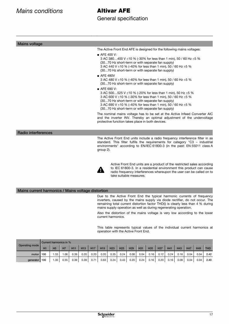
Required settings at the inverter It is absolutely necessary to carry out the following settings for all frequency inverters connected to an Active Front End:
AFE [Regen. connection] in menu [1.7 APPLICATION FUNCT.] (FUn-) in submenu [REGEN. CONNECTION] (OIr-) Setting: [Yes] (YES)
Thereby the undervoltage level of the frequency inverter is adapted to the operation with the Active Front End.
Please contact our service team if this parameter is not available in the parameter list of your device!
brA [Braking balance] in menu [1.7 APPLICATION FUNCT.] (FUn-) in submenu [RAMP TYPE] (rPt-) Setting: [No] (nO)
dEC [Deceleration] in menu [1.7 APPLICATION FUNCT.] (FUn-) in submenu [RAMP TYPE] (rPt-) For dynamic processes a very short deceleration ramp can cause an overload on the DC-bus with an overvoltage fault shut-
down.
This can be prevented by an extension or rounding of the deceleration ramp (parameters tA3 [Begin Dec round]; tA4 [End Dec
round]).
UrES [Mains voltage] in menu [1.8 FAULT MANAGEMENT] (FLt-) in submenu [UNDERVOLTAGE MGT.] (USb-) Same setting as the Active Front End.
Thereby the internal voltage levels of the frequency inverter are adapted.
IPL [Input phase loss] in menu [1.8 FAULT MANAGEMENT] (FLt-) in submenu [INPUT PHASE LOSS] (OPL-) Setting: [Ignore] (nO)
bUb [Brake res. fault Mgt] in menu [1.8 FAULT MANAGEMENT] (FLt-) in submenu [BU PROTECTION] (bUF-) Setting: [Ignore] (nO)
tCt [2 wire type] in menu [1.5 INPUTS/OUTPUTS CFG] (I-O-) Setting: [Level] (LEL)
In order to ensure an automatic restart by the AFE after an undervoltage recognition. An automatic restart only possible with 2-
wire control.
RFI filter The integrated RFI filter has to be deactivated (position IT, non-grounded mains) at all devices because there exists no direct
mains connection of the frequency inverter in case of operation with an Active Front End.
Non-observance of these precautions may cause material damage.
The 24 V control voltage of the Active Front End AFE can also be used to buffer the control electronics of the frequency
inverter.
When the frequency inverter is supplied via the DC link an external supply for the device fans is required!
Via the LFM (line filter module) it is possible to supply the device fans with up to 4 additional inverters (with the same power
as the AIC).
Specification Altivar AFE Common DC bus
35
Common DC bus
Specification
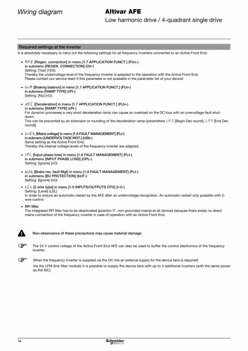
Description The Active Front End supplies a common DC bus at which several inverters
INV are connected. This enables an energy exchange between the individual
motor drives.
This concept is advantageous when there is a "load conjunction" that leads to
motor and generator operation of the individual inverters at the same time.
Thus, dimensioning of the Active Front End can be reduced to the required
acceleration and braking power of the of the whole drive unit.
Examples therefor are:
■ Test benches
(driving a shaft that is braked at the same time in order to test loads)
■ Belt drives
(winding up and off the belt with permanent traction)
M
M
M
AFE (Active Front End)
3~
Main
ssu
pply
50
/60
Hz LFM
Line FilterModule
LFC
LineFilter
Choke
AIC
ActiveInfeed
Converter
INV 1
Inverter
INV 2
Inverter
INV 3
Inverter
DC bus
Inverters of different power can be operated at the common DC bus.
Depending on the power demand individual Active Front End units can be
locked or released during operation.
However, connection and disconnection must be only executed when there is
no voltage!
Take care of correct fuse protection of all inverters.
Next to the performance record also the maximum possible load
capacity of the Active Front End has to be observed when
dimensioning.
Please observe the information and notes about the inverters in
chapter "Inverter", page 92 and the device documentation provided
on the CD-ROM which is attached to each inverter.

Specification Altivar AFE Common DC bus
36
Dimensioning
Pay attention to following points when several inverters are operated at a
common DC bus:
■ Total DC power
Check the sum of the motor power and the generator power at the DC bus
separately. The higher value determines the selection of the Active Front
End.
■ Capacity of the DC bus
In order to avoid overload of the charging circuit of the Active Front End,
observe the sum of the capacities of all inverters connected to the DC bus.
Active Front End for 400 V mains
Continuous DC power Load Active Front End AFE
[kW] capacity Active Infeed Converter AIC Line Filter Module LFM Line Filter Choke LFC
400 V [mF] Type Reference Type Reference Type Reference 120 30 4V120 VW3A7250 4V120 VW3A7260 4V120 VW3A7265
143 40 4V145 VW3A7251 4V175 VW3A7261 4V175 VW3A7266
172 40 4V175 VW3A7252 4V175 VW3A7261 4V175 VW3A7266
238 80 4V240 VW3A7253 4V340 VW3A7262 4V340 VW3A7267
268 80 4V275 VW3A7254 4V340 VW3A7262 4V340 VW3A7267
336 80 4V340 VW3A7255 4V340 VW3A7262 4V340 VW3A7267
425 160 4V430 VW3A7256 2x4V340 2xVW3A7262 2x4V340 2xVW3A7267
530 160 4V540 VW3A7257 2x4V340 2xVW3A7262 2x4V340 2xVW3A7267
665 160 4V675 VW3A7258 2x4V340 2xVW3A7262 2x4V340 2xVW3A7267
Active Front End for 480 V mains
Continuous DC power Load Active Front End AFE
[kW] capacity Active Infeed Converter AIC Line Filter Module LFM Line Filter Choke LFC
480 V [mF] Type Reference Type Reference Type Reference 130 30 4V120 VW3A7250 4V120 VW3A7260 4V120 VW3A7265
162 40 4V145 VW3A7251 4V175 VW3A7261 4V175 VW3A7266
162 40 4V175 VW3A7252 4V175 VW3A7261 4V175 VW3A7266
277 80 4V240-13 VW3A7283 4V340 VW3A7262 4V340 VW3A7267
315 80 4V275 VW3A7254 4V340 VW3A7262 4V340 VW3A7267
390 80 4V340 VW3A7255 4V340 VW3A7262 4V340 VW3A7267
490 160 4V430-15 VW3A7286 2x4V340 2xVW3A7262 2x4V340 2xVW3A7267
610 160 4V540-15 VW3A7287 2x4V340 2xVW3A7262 2x4V340 2xVW3A7267
770 160 4V675 VW3A7258 2x4V340 2xVW3A7262 2x4V340 2xVW3A7267
Active Front End for 500 / 690 V mains
Continuous DC power Load Active Front End AFE
[kW] capacity Active Infeed Converter AIC Line Filter Module LFM Line Filter Choke LFC
500 V 600 V 690 V [mF] Type Reference Type Reference Type Reference 102 123 142 16 6V145 VW3A7270 1) 6V220 VW3A7263 6V220 VW3A7268
127 153 172 16 6V175 VW3A7271 1) 6V220 VW3A7263 6V220 VW3A7268
157 162 215 16 6V220 VW3A7272 1) 6V220 VW3A7263 6V220 VW3A7268
193 230 268 32 6V275 VW3A7273 1) 6V430 VW3A7264 6V430 VW3A7269
242 290 335 32 6V340 VW3A7274 1) 6V430 VW3A7264 6V430 VW3A7269
305 365 424 32 6V430 VW3A7275 1) 6V430 VW3A7264 6V430 VW3A7269
382 460 528 64 6V540 VW3A7276 2) 2x6V430 2xVW3A7264 2x6V430 2xVW3A7269
478 575 663 64 6V675 VW3A7277 2) 2x6V430 2xVW3A7264 2x6V430 2xVW3A7269
607 730 842 64 6V860 VW3A7278 2) 2x6V430 2xVW3A7264 2x6V430 2xVW3A7269
1.) ... additionally the option Fan wiring 6V (VW3 A7 280) has to be ordered 1x
2.) ... additionally the option Fan wiring 6V (VW3 A7 280) has to be ordered 2x
Further technical data can be found in chapter "Technical data".

Examples for calculation Altivar AFE Common DC bus
37
Examples for calculation
Winch
In this example the winch is operated by an inverter and it is braked by a further drive. A mains voltage is 400 V is expected.
In order to select the Active Front End, the performance record and the total charging capacity at the DC bus have to be checked.
The drive is realised with a ATV71HC25N4D frequency inverter. Thus the inverter has to be supplied with a DC power of 270 kW, as
specified in the tables chapter "Inverter", page 92.
For braking of the second shaft a ATV71HC20N4D is used. As this inverter is used to return energy to the mains, its generator power
is deducted from the required DC power of the system.
As the capacities at the DC bus (independent of the energy direction) have to be charged by the Active Front End, they have to be
added.
Inverter Power Energy direction Capacity
ATV71HC20N4D 180 kW generator 14 mF
ATV71HC25N4D 270 kW motor 20 mF
Sum 90 kW motor 34 mF
In this example, due to the capacity the Active Front End with a load capacity of
40 mF is selected, consisting of following components:
AIC 4V145 VW3A7251
LFM 4V175 VW3A7261
LFC 4V175 VW3A7266
Load capacity:
40 mF
For drive groups with nearly balanced performance record, typically the load
capacity of the Active Front End is determining the selection of the device.

Examples for calculation Altivar AFE Common DC bus
38
Roller conveyor
In this example the roller conveyor is operated by several inverters. A mains voltage is 400 V is expected.
In order to select the Active Front End, the performance record and the total charging capacity at the DC bus have to be checked.
The drives are realised with ATV61HD30N4 frequency inverters. Thus each inverter has to be supplied with a DC power of 34 kW, as
specified in the tables in chapter "Inverter", page 92.
As the capacities at the DC bus (independent of the energy direction) have to be charged by the Active Front End, they have to be
added.
Inverter Power demand Capacity
6x ATV61HD30N4 6x 34 kW motor 6x
2 mF
Sum 204 kW motor 12 mF
In this example, due to the performance record the Active Front End is selected, which is able to supply the DC-bus with 204 kW. It
consists of the following components:
AIC 4V240 VW3A7253
LFM 4V340 VW3A7262
LFC 4V340 VW3A7267
DC power:
238 kW
For drive groups with predominant motor power, the power sum of all inverters is determining the selection of the Active Front End.

Wiring diagram Altivar AFE Common DC bus
39
Wiring diagram
Power wiring The Active Front End consists of three components in principle: the Line Filter
Module LFM, the Line Filter Choke LFC and the Active Infeed Converter AIC.
The 3-phase mains connection is done at the Line Filter Module LFM. Further
power connection is done via the Line Filter Choke LFC (3 single phase
chokes) to the Active Infeed Converter AIC.
In the power range to 340 kW (up to 430 kW at 500 / 690 V) one LFM and one
LFC (consisting of three parts) is connected upstream to the Active Infeed
Converter AIC.
3L1
3L2
3L3
PA/+
PC/-
1L1
1L2
1L3
2L1
2L2
2L3
1
1
1
2
2
2
LFM LFC AIC
Active Front End AFE
L1
L2
L3
Q1
F1
F3
In the power range from 430 kW (from 540 kW at 500 / 690 V) the Active Front
End consists of an AIC, two LFMs and two LFCs (each consisting of three
single phase chokes).
3L1
3L2
3L3
PA/+
PC/-
1L1
1L2
1L3
2L1
2L2
2L3
1
1
1
2
2
2
LFM LFC AIC
Active Front End AFE
1L1
1L2
1L3
2L1
2L2
2L3
1
1
1
2
2
2
LFM LFC
L1 L2 L3
Q1
F1
F3
F4
F6
In case of the common DC bar all inverters are connected to the DC output of
the Active Front End AFE.

Wiring diagram Altivar AFE Common DC bus
40
Basically the expansion of the DC bus should be kept as small as
possible. The distance between the components (AIC, INV) must not
exceed 3m. Arrangements with longer DC wiring must be checked
and damping elements to avoid resonances have to built in when
required. Further information is available on request.
In case of faulty wiring of the DC link, e.g. due to exchanging
terminals PA/+ and PC/- or an earth fault, the inverter as well as the
Active Front End may be damaged or destroyed.

Wiring diagram Altivar AFE Common DC bus
41
Internal control wiring Fan supply and control voltage
The voltage for fan supply and the control voltage are generated in the line
filter module LFM.
The control wiring between the line filter module LFM and the Active Infeed
Converter AIC is realized by the provided connecting cables W2 and W3. As
soon as mains voltage is applied to the terminals 1L1, 1L2, 1L3, a 24 V
auxiliary voltage is produced to supply the Active Infeed Converter AIC. It can
be also used to buffer the control electronics of one inverter INV.
For the 400 V devices (except VW3 A7 250 due to DC fans) the cable W1 has
to be connected to the line filter module LFM in order to supply the fans in the
Active Infeed Converter AIC. The fans in the inverter INV are supplied from the
drive side between the terminals 4/5/6 in the line filter module LFM and the
auxiliary terminal block R0/S0/T0 (switching to external supply) in the INV.
With the fan supply it is possible to operate all fans of the Active Infeed
Converter AIC and the fans of up to four inverters.
L1
L2
L3
1L1
1L2
1L3
2L1
2L2
2L3
L1
L2
L3
K1
K2
Q1(RFI)
3 AC 380...480V50/60 Hz
FDR
3L3
3L2
3L1
PA/+
PC/-
FB
LFM AIC
1
1
1
2
2
2
LFC
RFI
PA/+
PC/-
INV
FB
W
V
U
M
furtherINV
Control voltage24V DC
Control part Control part
Active Front End AFE
Fan Fan
Fuse
The inverters INV of the types
ATV61H075N4 ... HC11N4
ATV71H075N4 ... HD90N4
do not require an external fan supply from the line filter module
LFM.
The fans are internally protected when supplyed via the line filter
module LFM. Therefore no additional fuses are required.

Wiring diagram Altivar AFE Common DC bus
42
For the 690 V devices the fans are supplied via the transformer box at the top
side of the devices. The connection to the Active Infeed Converter AIC is
included in delivery and has to be connected to the line filter module LFM only.
The fans in the inverter INV are supplied from the drive side between the
terminals 4/5/6 in the line filter module LFM and the transformer box at the top
side of the INV. Therefore a terminal module is necessary (deliverable as option
"Fan wiring 6V" with reference number VW3A7280)
L1
L2
L3
1L1
1L2
1L3
2L1
2L2
2L3
L1
L2
L3
K1
K2
Q1(RFI)
3 AC 500...690V50/60 Hz
FDR
3L3
3L2
3L1
PA/+
PC/-
LFM AIC
1
1
1
2
2
2
LFC
RFI
PA/+
PC/-
INV
W
V
U
MFBFB
furtherINV
Control voltage24V DC
Control part Control part
Trafobox
Active Front End AFE
Trafobox
FanFan
Fuse
The fans are internally protected when supplyed via the line filter
module LFM. Therefore no additional fuses are required.
For fan supply of the inverter(s) INV it is necessary to order the option
"Fan wiring 6V" with reference number VW3A7280.
1x VW3A7280 for ATV61HC11Y...C40Y; ATV71HC11Y...C31Y
2x VW3A7280 for ATV61HC50Y...C80Y; ATV71HC40Y...C63Y

Wiring diagram Altivar AFE Common DC bus
43
Terminal connections
The following presentation shows the wiring of the control terminals between
the line filter module LFM and the Active Infeed Converter AIC.
The wiring is significantly simplified by means of two ready-made cables with
plugs which are already connected to the AIC. The cables are designed for a
maximum distance of 1 m between AIC and LFM.
At 400 V devices up to 340 kW and at 690 V devices up to 430 kW, the Active
Infeed Converter AIC is connected with only one LFM. In case of higher power
the AIC is connected with two LFMs.
COM
AI2
0V
LI1
LI2
LI3
LI4
LI5
LI6
+24
PWR
R1A
R1B
R1C
R2A
R2C
COM
AO1
P24
X1:6
X1:5
X1:4
X1:3
X1:2
X1:1
2
1
0V
P24
X
X20
X1:6
X1:5
X1:4
X1:3
X1:2
X1:1
X3
X2
X3
X2
External fault
EmergencyOFF
Ground
24 V DC supply INV
Start / Stop
External reset
AIC (Basic device)
Ground
Analog input 0 (4)...20mA
0 V
Start AFE (2/3-wire)
Stop AFE (3-wire)
External fault
Lock (Emergency OFF)
+24 V DC for logic inputs
Lock (Power Removal)
Programmable contactFactory setting: Run
Analog output 0 (4)...20mA
External 24V DC supply
Start LFM
External reset
Feedback LFM
Plug (at measurement board)
Line filter module LFM
Fan INV L3
PE
Fan AIC L1
Fan AIC L2
Fan AIC L3
Fan INV L2
PE
Fan INV L1
2nd Line filter module LFM
Fan INV L3
PE
Fan AIC L1
Fan AIC L2
Fan AIC L3
Fan INV L2
PE
Fan INV L1
(only at high power)
0...+10 Vdc0(4)...20 mA

Wiring diagram Altivar AFE Common DC bus
44
+24
LI7
LI8
LI9
LI10
0V
R3A
R3B
R3C
LO1
LO2
Source
Int.
Ext.
Sin
k
SW3
0 V
CLO
0V
AIC (Option card)
0 V
+24 V DC for logic inputs
Emergency operation AFE
not used
not used
Programmable contactFactory setting: Alarm
Programmable outputFactory setting: Overload
Imax 2 generator
Programmable contactFactory setting: DC On
Common
Emergency operation AFE
Imax 2 generator

Wiring diagram Altivar AFE Common DC bus
45
External control wiring The following diagrams show the control wiring when several inverters are
operated at an DC bus supplied by the Active Front End. Similar to the single
drive, there are several possibilities for control of the Active Front End.
The inverters supplied via the DC bus may have different power.
Ensure that the sum of the required DC power and the sum of the
capacities at the DC bus do not exceed the limits of the Active Infeed
Converter AIC.
The users are responsible to integrate the Active Front End units into
the protection and safety concept of the plant or machine.
In case of a mains failure during motor operation, the Active Front
End as well as the inverter recognise the undervoltage and react
according to their parameterization (impulse inhibit, alarm, trip). In
generator operation the inverter may not recognize a mains failure
always.
Control via start/stop signals
The Active Front End is controlled separately from the inverters by means of an
own start command.
In this case the Active Front End AFE and the inverters INV have to be
integrated separately to the superior control concept.
L1
L2
L3
1L1
1L2
1L3
Q1
3L3
3L2
3L1
PA/+
PC/-
LFM AIC
PA/+ PC/-
INV1W
V
U
M
2L1
2L2
2L3
1
1
1
2
2
2
LFC
PA/+ PC/-
INV2W
V
U
M
PWR PWR
No directinformation exchangebetween INV and AFE
Control part
Active Front End AFE
Control part
Message"Run"(INV1)
Start/Stopcommand
(INV1)
External communication
via logic inputsControlsignals
Message"Run"(AFE)
Start/Stopcommand
(AFE)
Fuse
EmergencyOFF
Control part
Message"Run"(INV2)
Start/Stop
(INV2)command
Control signals
DC bus
Control PLC

Wiring diagram Altivar AFE Common DC bus
46
Control via start/stop signals of the inverter
The Active Front End is not controlled by an own start command but via the
inverter.
L1
L2
L3
1L1
1L2
1L3
Q1
3L3
3L2
3L1
PA/+
PC/-
LFM AIC
PA/+ PC/-
INV1W
V
U
M
2L1
2L2
2L3
1
1
1
2
2
2
LFC
PA/+ PC/-
INV2W
V
U
M
PWR PWR
Control part
Active Front End AFE
Control part
Fuse
DC bus
Message"Run"(AFE + INV1)
EmergencyOFF
Message "Run" (AFE)
Start (AFE)
Op
tio
nfie
ldb
us
Control part
Message"Run"(INV2)
Control and monitoringvia fieldbus
Op
tio
nfie
ldb
us
Control PCL
The 24 V DC buffer voltage of the inverter, that controls the Active Front End, can be taken from the Active Infeed Converter
AIC.
When further inverters should be supplied with a buffer voltage, it has to be generated external.

Wiring diagram Altivar AFE Common DC bus
47
Control of the Active Front End via mains connection/disconnection
It is also possible with a common DC bus to operate the Active Front End
without additional control. In this case the Active Front End starts as soon as
voltage is recognised at the input.
L1
L2
L3
1L1
1L2
1L3
Q1
3L3
3L2
3L1
PA/+
PC/-
LFM AIC
PA/+ PC/-
INV1W
V
U
M
2L1
2L2
2L3
1
1
1
2
2
2
LFC
PA/+ PC/-
INV2W
V
U
M
PWR PWR
Only status signals No directinformation exchangebetween INV and AFE
Control part
Active Front End AFE
Control part
Message"Run"(INV1)
Start/Stopcommand
(INV1)
Control signals
Message"Run"(AFE)
Fuse
EmergencyOFF
Control part
Message"Run"(INV2)
Start/Stop
(INV2)command
Control signals
DC bus
Auto-start
Control PCL
In case of a mains failure during motor operation, the Active Front End as well as the inverter recognise the undervoltage and
react according to their parameterization (impulse inhibit, alarm, trip). In generator operation the inverter may not recognize a
mains failure always.
The 24 V DC buffer voltage of an inverter INV can be taken from the Active Infeed Converter AIC. When further inverters
should be supplied with a buffer voltage, it has to be generated external.

Wiring diagram Altivar AFE Common DC bus
48
Control of the Active Front End via direct fieldbus control
When the communication at the control system takes place with CANopen or
Modbus, the inverters and the Active Infeed Converter can be directly
connected to and controlled by the bus system.
L1
L2
L3
1L1
1L2
1L3
Q1
3L3
3L2
3L1
PA/+
PC/-
LFM AIC
PA/+ PC/-
INV1W
V
U
M
2L1
2L2
2L3
1
1
1
2
2
2
LFC
PA/+ PC/-
INV2W
V
U
M
PWR PWR
Control part
Active Front End AFE
Control part
Fuse
Control part
DC bus
Message"Run"(INV1)
EmergencyOFF
Control and monitoringvia CANopen or Modbus
Message"Run"(AFE)
CANopen or Modbus
Message"Run"(INV2)
Control PLC
The 24 V DC buffer voltage of an inverter INV can be taken from the Active Infeed Converter AIC. When further inverters
should be supplied with a buffer voltage, it has to be generated external.

Wiring diagram Altivar AFE Common DC bus
49
Control of the Active Front End via indirect fieldbus control
The Active Front End is controlled and monitored by means of the option card
"communication bridge" of the inverter. The connection to the Active Front
End AFE is done via CANopen.
By using a fieldbus option card it is possible to control the inverter as well as
the Active Infeed Converter via the inverter. Therefor each fieldbus system,
which is available for the inverter, can be used.
L1
L2
L3
1L1
1L2
1L3
Q1
3L3
3L2
3L1
PA/+
PC/-
LFM AIC
PA/+ PC/-
INV1W
V
U
M
2L1
2L2
2L3
1
1
1
2
2
2
LFC
PA/+ PC/-
INV2W
V
U
M
PWR PWR
Control part
Active Front End AFE
Control part
Fuse
DC bus
Control and monitoringvia fieldbus
Control PLC
Message"Run"(INV1)
EmergencyOFF
Control and
monitoringAFE via CANopen
Option
field
bus
Message"Run"(AFE)
Option
com
m.b
r.
Control part
Message"Run"(INV2)
Option
field
bus
The 24 V DC buffer voltage of an inverter INV can be taken from the Active Infeed Converter AIC. When further inverters
should be supplied with a buffer voltage, it has to be generated external.

Specification Altivar AFE Active Front End units parallel
50
Active Front End units parallel
Specification
Description In case of parallel connection of several Active Front End units AFE they supply
a common DC bus. Thus it is possible to ensure a higher power at the DC bus
or to increase reliability due to redundancy. Up to four Active Front End units
can be connected in parallel. Several inverters of different power can be
operated at the DC bus. This enables also balance of energy at the DC link.
M
M
M
3~ Mains supply50 / 60 Hz
DC bus
Syn
ch
ron
isatio
n
AFE 1 (Active Front End)
AFE 2 (Active Front End)
LFM
Line FilterModule
LFC
LineFilter
Choke
AIC
ActiveInfeed
Converter
INV 2
Inverter
AFE 3 (Active Front End)
LFM
Line FilterModule
LFC
LineFilter
Choke
AIC
ActiveInfeed
Converter
INV 3
Inverter
LFM
Line FilterModule
LFC
LineFilter
Choke
AIC
ActiveInfeed
Converter
INV 1
Inverter
Parallel connection of the Active Front End units is possible without derating.
Units of different power can be operated parallel whereas the smallest AFE unit
should not be less than 50 % of the power of the biggest unit.
Depending on the power demand individual Active Front End units can be
locked or released during operation.
However, connection and disconnection must be only executed when there is
no voltage!
Take care of correct fuse protection of all components connected to
the DC bus.
Please observe the information and notes about the inverters in
chapter "Inverter", page 92 and the device documentation provided
on the CD-ROM which is attached to each inverter.

Specification Altivar AFE Active Front End units parallel
51
Dimensioning
Pay attention to following points when several inverters are operated at a
common DC bus that is supplied by one or several Active Front End units:
■ Total DC power
Add the required DC power of all drives that are connected to a DC bus,
which is supplied by an Active Front End. Thereby you have to check the
motor and generator powers.
The DC link power of all connected inverters must not exceed the sum of the
DC link power of the Active Front End units.
■ Capacity of the DC bus
In order to avoid overload of the charging circuit of the Active Front End,
observe the sum of the capacities of all inverters connected to the DC bus.
The connected capacities must not be higher than the load capacity of the
Active Front End units.
■ AFE type
It is possible to connect two different types of Active Front End units parallel.
However, the smallest Active Front End should not be less than 50 % of the
power of the biggest unit.
Nevertheless we recommend to connect only Active Front End units of same
type parallel.
Active Front End for 400 V mains
Continuous DC power Load Active Front End AFE
[kW] capacity Active Infeed Converter AIC Line Filter Module LFM Line Filter Choke LFC
400 V [mF] Type Reference Type Reference Type Reference 120 30 4V120 VW3A7250 4V120 VW3A7260 4V120 VW3A7265
143 40 4V145 VW3A7251 4V175 VW3A7261 4V175 VW3A7266
172 40 4V175 VW3A7252 4V175 VW3A7261 4V175 VW3A7266
238 80 4V240 VW3A7253 4V340 VW3A7262 4V340 VW3A7267
268 80 4V275 VW3A7254 4V340 VW3A7262 4V340 VW3A7267
336 80 4V340 VW3A7255 4V340 VW3A7262 4V340 VW3A7267
425 160 4V430 VW3A7256 2x4V340 2xVW3A7262 2x4V340 2xVW3A7267
530 160 4V540 VW3A7257 2x4V340 2xVW3A7262 2x4V340 2xVW3A7267
665 160 4V675 VW3A7258 2x4V340 2xVW3A7262 2x4V340 2xVW3A7267
Active Front End for 480 V mains
Continuous DC power Load Active Front End AFE
[kW] capacity Active Infeed Converter AIC Line Filter Module LFM Line Filter Choke LFC
480 V [mF] Type Reference Type Reference Type Reference 130 30 4V120 VW3A7250 4V120 VW3A7260 4V120 VW3A7265
162 40 4V145 VW3A7251 4V175 VW3A7261 4V175 VW3A7266
162 40 4V175 VW3A7252 4V175 VW3A7261 4V175 VW3A7266
277 80 4V240-13 VW3A7283 4V340 VW3A7262 4V340 VW3A7267
315 80 4V275 VW3A7254 4V340 VW3A7262 4V340 VW3A7267
390 80 4V340 VW3A7255 4V340 VW3A7262 4V340 VW3A7267
490 160 4V430-15 VW3A7286 2x4V340 2xVW3A7262 2x4V340 2xVW3A7267
610 160 4V540-15 VW3A7287 2x4V340 2xVW3A7262 2x4V340 2xVW3A7267
770 160 4V675 VW3A7258 2x4V340 2xVW3A7262 2x4V340 2xVW3A7267

Specification Altivar AFE Active Front End units parallel
52
Active Front End for 500 / 600 / 690 V mains
Continuous DC power Load Active Front End AFE
[kW] capacity Active Infeed Converter AIC Line Filter Module LFM Line Filter Choke LFC
500 V 600 V 690 V [mF] Type Reference Type Reference Type Reference 102 123 142 16 6V145 VW3A7270 1) 6V220 VW3A7263 6V220 VW3A7268
127 153 172 16 6V175 VW3A7271 1) 6V220 VW3A7263 6V220 VW3A7268
157 162 215 16 6V220 VW3A7272 1) 6V220 VW3A7263 6V220 VW3A7268
193 230 268 32 6V275 VW3A7273 1) 6V430 VW3A7264 6V430 VW3A7269
242 290 335 32 6V340 VW3A7274 1) 6V430 VW3A7264 6V430 VW3A7269
305 365 424 32 6V430 VW3A7275 1) 6V430 VW3A7264 6V430 VW3A7269
382 460 528 64 6V540 VW3A7276 2) 2x6V430 2xVW3A7264 2x6V430 2xVW3A7269
478 575 663 64 6V675 VW3A7277 2) 2x6V430 2xVW3A7264 2x6V430 2xVW3A7269
607 730 842 64 6V860 VW3A7278 2) 2x6V430 2xVW3A7264 2x6V430 2xVW3A7269
3.) ... additionally the option Fan wiring 6V (VW3 A7 280) has to be ordered 1x
4.) ... additionally the option Fan wiring 6V (VW3 A7 280) has to be ordered 2x
DC bus capacities for 400 V – 440 V mains
Active Infeed Converter AIC DC fuse Recommended type of fuse DC capacity
Type Reference [A] Ferraz Shawmut 1) Bussmann 2) [mF] 4V120 VW3A7250 250 12.5 URD 70 TTF 0250 170M3395 6.5
4V145 VW3A7251 315 12.5 URD 71 TTF 0315 170M3396 9.8
4V175 VW3A7252 350 12.5 URD 71 TTF 0350 170M3397 9.8
4V240 VW3A7253 500 12.5 URD 72 TTF 0500 170M4445 13
4V275 VW3A7254 550 12.5 URD 72 TTF 0550 170M4446 14
4V340 VW3A7255 700 12.5 URD 73 TTF 0700 170M5447 20
4V430 VW3A7256 2x450 2x 12.5 URD 72 TTF 0450 2x 170M4394 21
4V540 VW3A7257 2x550 2x 12.5 URD 72 TTF 0550 2x 170M4446 30
4V675 VW3A7258 2x700 2x 12.5 URD 73 TTF 0700 2x 170M5447 39
1.) ... Ferraz Shawmut - Protistor semiconductor fuse PSC aR sizes 7x – 1250/1300Vac
2.) ... Bussmann - High speed fuse square body flush end contact – 1250/1300Vac
DC bus capacities for 480 V mains (UL)
Active Infeed Converter AIC DC fuse Recommended type of fuse DC capacity Type Reference [A] Ferraz Shawmut 1) Bussmann 2) [mF] 4V120 VW3A7250 250 A130 URD 70 TTI 0250 170M3395 6.5
4V145 VW3A7251 315 A130 URD 71 TTI 0315 170M3396 9.8
4V175 VW3A7252 350 A130 URD 71 TTI 0350 170M3397 9.8
4V240-13 VW3A7283 500 A130 URD 72 TTI 0500 170M4445 14
4V275 VW3A7254 550 A130 URD 72 TTI 0550 170M4446 14
4V340 VW3A7255 700 A130 URD 73 TTI 0700 170M5447 20
4V430-15 VW3A7286 2x450 2x A130 URD 72 TTI 0450 2x 170M4394 39
4V540-15 VW3A7287 2x550 2x A130 URD 72 TTI 0550 2x 170M4446 39
4V675 VW3A7258 2x700 2x A130 URD 73 TTI 0700 2x 170M5447 39
1.) ... Ferraz Shawmut - Protistor semiconductor fuse PSC aR sizes 7x – 1250/1300Vac
2.) ... Bussmann - High speed fuse square body flush end contact – 1250/1300Vac

Specification Altivar AFE Active Front End units parallel
53
DC bus capacities for 500 / 690 V mains Active Infeed Converter AIC DC fuse Recommended type of fuse DC capacity Type Reference [A] Ferraz Shawmut 1) Bussmann 2) [mF] 6V145 VW3A7270 160 CC 7.5 gRC 120 TTF 0160 170E3581 3.9
6V175 VW3A7271 200 CC 7.5 gRC 121 TTF 0200 170E5417 3.9
6V220 VW3A7272 250 CC 7.5 gRC 121 TTF 0250 170E5418 3.9
6V275 VW3A7273 315 CC 7.5 gRC 122 TTF 0315 170E8336 7.8
6V340 VW3A7274 400 CC 7.5 gRC 122 TTF 0400 170E8337 7.8
6V430 VW3A7275 500 CC 7.5 gRC 123 TTF 0500 170E9681 7.8
6V540 VW3A7276 630 2x CC 7.5 gRC 122 TTF 0630 2x 170E8336 16
6V675 VW3A7277 800 2x CC 7.5 gRC 122 TTF 0800 2x 170E8337 16
6V860 VW3A7278 1000 2x CC 7.5 gRC 123 TTF 1000 2x 170E9681 16
1.) ... Ferraz Shawmut - Protistor semiconductor fuse PSC aR sizes 7x – 1250/1300Vac
2.) ... Bussmann - High speed fuse square body flush end contact – 1250/1300Vac
DC bus capacities for 600 V mains (UL/CSA)
Active Infeed Converter AIC DC fuse Recommended type of fuse DC capacity
Type Reference [A] Bussmann 1) [mF] 6V145 VW3A7270 160 170M1826 3.9
6V175 VW3A7271 200 170M1827 3.9
6V220 VW3A7272 250 170M1828 3.9
6V275 VW3A7273 315 170M1829 7.8
6V340 VW3A7274 400 170M1831 7.8
6V430 VW3A7275 500 170M1833 7.8
6V540 VW3A7276 2x315 2x 170M1829 16
6V675 VW3A7277 2x400 2x 170M1831 16
6V860 VW3A7278 2x500 2x 170M1833 16
1.) ... Bussmann - High speed fuse square body flush end contact – 1250/1300Vac
Further technical data can be found in chapter "Technical data".
Generally also other models and types of fuses can be used provided that their electrical data are comparable.
In order to meet the requirements of UL/CSA, the specified fuse types have to be used.

Examples for calculation Altivar AFE Active Front End units parallel
54
Examples for calculation
Parallel connection
In this example two Active Front End units supply a common DC bus at which several inverters are operated. A mains voltage is 400 V
is expected.
The two Active Front End units are used to reach a higher power at the DC bus. The control has to ensure that both Active Front End
units are controlled simultaneously. It is not necessary to take the capacity of the Active Front End units into account because the
Active Front End itself supplies its capacities.
In case of parallel connection due to increase redundancy, the capacity of the Active Front End has to be observed because the
supply of the whole DC bus has to be provided if the Active Front End breaks down.
In order to select the Active Front End units, the performance record and the total charging capacity at the DC bus have to be
checked.
3 pieces ATV61HC11N4D and 2 pieces ATV61HC31N4D are used as inverters. Thus each inverter needs a DC power of 120 kW or
330 kW, as specified in the previous tables.
As the capacities at the DC bus (independent of the energy direction) have to be charged by the Active Front End, they have to be
added.
Inverter Power demand Capacity
ATV61HC11N4D 120 kW motor 6.5 mF
ATV61HC11N4D 120 kW motor 6.5 mF
ATV61HC11N4D 120 kW motor 6.5 mF
ATV61HC31N4D 330 kW motor 20 mF
ATV61HC31N4D 330 kW motor 20 mF
Sum 1020 kW motor 59.5 mF
Due to the parallel connection, two Active Front End units of same type are selected. Based on the performance record the following
two Active Front End units are selected, consisting of following components:
2x 1x AIC 4V540 VW3A7257
2x 2x LFM 4V340 VW3A7262
2x 2x LFC 4V340 VW3A7267
Total power (of both AFEs): 1060 kW
Load capacity (per AFE): 160 mF
Due to the tolerances of components, the load sharing between the two AFEs may differ up to 40 % in partial-load range.
When connecting two or more AFEs parallel to increase the total power, it has to be ensured by the superior control that
all AFEs are ready to run and that they are started simultaneously (within 100ms). Derating by parallel connection is not
required.

Wiring diagram Altivar AFE Active Front End units parallel
55
Wiring diagram
Power wiring The Active Front End consists of three components in principle: the Line Filter
Module LFM, the Line Filter Choke LFC and the Active Infeed Converter AIC.
The 3-phase mains connection is done at the Line Filter Module LFM. Further
power connection is done via the Line Filter Choke LFC (3 single phase
chokes) to the Active Infeed Converter AIC.
In the power range to 340 kW (up to 430 kW at 500 / 690 V) one LFM and one
LFC (consisting of three parts) is connected upstream to the Active Infeed
Converter AIC.
3L1
3L2
3L3
PA/+
PC/-
1L1
1L2
1L3
2L1
2L2
2L3
1
1
1
2
2
2
LFM LFC AIC
Active Front End AFE
L1
L2
L3
Q1
F1
F3
In the power range from 430 kW (from 540 kW at 500 / 690 V) the Active Front
End consists of an AIC, two LFMs and two LFCs (each consisting of three
single phase chokes).
3L1
3L2
3L3
PA/+
PC/-
1L1
1L2
1L3
2L1
2L2
2L3
1
1
1
2
2
2
LFM LFC AIC
Active Front End AFE
1L1
1L2
1L3
2L1
2L2
2L3
1
1
1
2
2
2
LFM LFC
L1 L2 L3
Q1
F1
F3
F4
F6
In case of parallel connection of Active Front End units they are connected to
all inverters via a DC bus.

Wiring diagram Altivar AFE Active Front End units parallel
56
Basically the expansion of the DC bus should be kept as small as
possible. The distance between the components (AIC, INV) must
not exceed 3m. Arrangements with longer DC wiring must be
checked and damping elements to avoid resonances have to built
in when required. Further information is available on request.
In case of faulty wiring of the DC link, e.g. due to exchanging
terminals PA/+ and PC/- or an earth fault, the inverter as well as the
Active Front End may be damaged or destroyed.

Wiring diagram Altivar AFE Active Front End units parallel
57
Internal control wiring The voltage for fan supply and the control voltage are generated in the line
filter module LFM.
The control wiring between the line filter module LFM and the Active Infeed
Converter AIC is realized by the provided connecting cables W2 and W3. As
soon as mains voltage is applied to the terminals 1L1, 1L2, 1L3, a 24 V
auxiliary voltage is produced to supply the Active Infeed Converter AIC. It can
be also used to buffer the control electronics of one inverter INV.
For the 400 V devices (except VW3 A7 250 due to DC fans) the cable W1 has
to be connected to the line filter module LFM in order to supply the fans in the
Active Infeed Converter AIC. The fans in the inverter INV are supplied from the
drive side between the terminals 4/5/6 in the line filter module LFM and the
auxiliary terminal block R0/S0/T0 (switching to external supply) in the INV.
With the fan supply it is possible to operate all fans of the Active Infeed
Converter AIC and the fans of up to four inverters.
L1
L2
L3
1L1
1L2
1L3
2L1
2L2
2L3
L1
L2
L3
K1
K2
Q1(RFI)
3 AC 380...480V50/60 Hz
FDR
3L3
3L2
3L1
PA/+
PC/-
FB
LFM AIC
1
1
1
2
2
2
LFC
RFI
PA/+
PC/-
INV
FB
W
V
U
M
furtherINV
Control voltage24V DC
Control part Control part
Active Front End AFE
Fan Fan
Fuse
The inverters INV of the types
ATV61H075N4 ... HC11N4
ATV71H075N4 ... HD90N4
do not require an external fan supply from the line filter module LFM.
The fans are internally protected when supplyed via the line filter module LFM. Therefore no additional fuses are required.
For parallel operation of Active Front End units an additional control line is required. It "synchronizes" the individual
Active Front End units.

Wiring diagram Altivar AFE Active Front End units parallel
58
For the 690 V devices the fans are supplied via the transformer box at the top
side of the devices. The connection to the Active Infeed Converter AIC is
included in delivery and has to be connected to the line filter module LFM only.
The fans in the inverter INV are supplied from the drive side between the
terminals 4/5/6 in the line filter module LFM and the transformer box at the top
side of the INV. Therefore a terminal module is necessary (deliverable as option
"Fan wiring 6V" with reference number VW3A7280)
L1
L2
L3
1L1
1L2
1L3
2L1
2L2
2L3
L1
L2
L3
K1
K2
Q1(RFI)
3 AC 500...690V50/60 Hz
FDR
3L3
3L2
3L1
PA/+
PC/-
LFM AIC
1
1
1
2
2
2
LFC
RFI
PA/+
PC/-
INV
W
V
U
MFBFB
furtherINV
Control voltage24V DC
Control part Control part
Trafobox
Active Front End AFE
Trafobox
FanFan
Fuse
For fan supply of the inverter(s) INV it is necessary to order the option "Fan wiring 6V" with reference number VW3A7280.
1x VW3A7280 for ATV61HC11Y...C40Y; ATV71HC11Y...C31Y
2x VW3A7280 for ATV61HC50Y...C80Y; ATV71HC40Y...C63Y

Wiring diagram Altivar AFE Active Front End units parallel
59
Terminal connections
The following presentation shows the wiring of the control terminals between
the line filter module LFM and the Active Infeed Converter AIC.
The wiring is significantly simplified by means of two ready-made cables with
plugs which are already connected to the AIC. The cables are designed for a
maximum distance of 1 m between AIC and LFM.
At 400 V devices up to 340 kW and at 690 V devices up to 430 kW, the Active
Infeed Converter AIC is connected with only one LFM. In case of higher power
the AIC is connected with two LFMs.
COM
AI2
0V
LI1
LI2
LI3
LI4
LI5
LI6
+24
PWR
R1A
R1B
R1C
R2A
R2C
COM
AO1
P24
X1:6
X1:5
X1:4
X1:3
X1:2
X1:1
2
1
0V
P24
X
X20
X1:6
X1:5
X1:4
X1:3
X1:2
X1:1
X3
X2
X3
X2
External fault
EmergencyOFF
Ground
24 V DC supply INV
Start / Stop
External reset
AIC (Basic device)
Ground
Analog input 0 (4)...20mA
0 V
Start AFE (2/3-wire)
Stop AFE (3-wire)
External fault
Lock (Emergency OFF)
+24 V DC for logic inputs
Lock (Power Removal)
Programmable contactFactory setting: Run
Analog output 0 (4)...20mA
External 24V DC supply
Start LFM
External reset
Feedback LFM
Plug (at measurement board)
Line filter module LFM
Fan INV L3
PE
Fan AIC L1
Fan AIC L2
Fan AIC L3
Fan INV L2
PE
Fan INV L1
2nd Line filter module LFM
Fan INV L3
PE
Fan AIC L1
Fan AIC L2
Fan AIC L3
Fan INV L2
PE
Fan INV L1
Syn
ch
ron
isa
tio
nlin
eto
the
ne
xtA
IC(o
nly
at
op
era
tio
nin
pa
ralle
l)
(only at high power)
Main switch Q1

Wiring diagram Altivar AFE Active Front End units parallel
60
+24
LI7
LI8
LI9
LI10
0V
R3A
R3B
R3C
LO1
LO2
Source
Int.
Ext.
Sin
k
SW3
0 V
CLO
0V
AIC (Option card)
0 V
+24 V DC for logic inputs
Emergency operation AFE
not used
not used
Programmable contactFactory setting: Alarm
Programmable outputFactory setting: Overload
Imax 2 generator
Programmable contactFactory setting: DC On
Common
Emergency operation AFE
Imax 2 generator
At parallel operation of 4 Active Front End units AFE an interruption of the synchronisation line may not be detected
definitely !
As soon as parameter 2.1.02 "Parallel operation" is set to "active", the analog outputs and inputs are not available any
longer because they are used for synchronisation.

Wiring diagram Altivar AFE Active Front End units parallel
61
External control wiring The following diagrams show the control wiring when several inverters are
operated at an DC bus supplied by several Active Front End units. There are
several possibilities for control of the Active Front End units.
For parallel operation of Active Front End units an additional control line is
required. It "synchronizes" the individual Active Front End units.
The inverters supplied via the DC bus may have different power.
Ensure that the sum of the required DC power and the sum of the
capacities at the DC bus do not exceed the limits of the Active Infeed
Converter AIC.
The users are responsible to integrate the Active Front End units into
the protection and safety concept of the plant or machine.
In case of a mains failure during motor operation, the Active Front
End as well as the inverter recognise the undervoltage and react
according to their parameterization (impulse inhibit, alarm, trip). In
generator operation the inverter may not recognize a mains failure
always.
When main switches Q1 are used in case of parallel connected Active
Front End units, they have to be integrated into the locking of the
Active Front End by means of an auxiliary contact (e.g. input PWR).

Wiring diagram Altivar AFE Active Front End units parallel
62
Control via start/stop signals
The Active Front End units are controlled separately from the inverters by
means of an own start command.
In this case the Active Front End units and the inverters have to be integrated
separately to the superior control concept.
For parallel operation of AFEs a connection between the Active Front End units
is required.
L1 L2 L3
1L1
1L2
1L3 3L3
3L2
3L1
PA/+
PC/-
LFM AIC
PA/+ PC/-
INV1W
V
U
M
2L1
2L2
2L3
1
1
1
2
2
2
LFC
PA/+ PC/-
INV2W
V
U
M
1L1
1L2
1L3
Q1
Q1
Q0
3L3
3L2
3L1
PA/+
PC/-
LFM AIC
2L1
2L2
2L3
1
1
1
2
2
2
LFC
PWR PWR
No directinformation exchangebetween INV and AFE
Control part
Active Front End AFE2
Control part
Message"Run"(INV1)
Start/Stop
(INV1)command
External communicationvia logic inputs
Control signals
Message"Run"(AFE2)
Start/Stopcommand
(AFE2)
Control part
Message"Run"(INV2)
Start/Stop
(INV2)command
Control signals
DC bus
Control part
Active Front End AFE1
Message"Run"(AFE1)
Start/Stopcommand
(AFE1)
Connection line forparallel operation
Control PLC

Wiring diagram Altivar AFE Active Front End units parallel
63
Control of the Active Front End via direct fieldbus control
The inverters INV as well as the Active Front End units can be tested and
monitored via CANopen or Modbus using the built-in interface.
For parallel operation of AFEs a connection between the Active Front End units
is required.
1L1
1L2
1L3 3L3
3L2
3L1
PA/+
PC/-
LFM AIC
PA/+ PC/-
INV1
2L1
2L2
2L3
1
1
1
2
2
2
LFC
PA/+ PC/-
INV2W
V
U
M
1L1
1L2
1L3 3L3
3L2
3L1
PA/+
PC/-
LFM AIC
2L1
2L2
2L3
1
1
1
2
2
2
LFC
L1 L2 L3
Q1
Q1
Q0
W
V
U
M
PWR PWR
Control part
Active Front End AFE2
Control part Control part
DC bus
Control part
Active Front End AFE1
Message"Run"(INV1)
Control and monitoringvia CANopen or Modbus
CANopen or Modbus
Message"Run"(INV2)
Control PLC
Message"Run"
(AFE1)
Message"Run"
(AFE1)
Connection line forparallel operation

Wiring diagram Altivar AFE Active Front End units parallel
64
Control of the Active Front End via indirect fieldbus control
When communication at the control system is not realized with CANopen or
Modbus but with another fieldbus system, the option card "communication
bridge" is required. Combined with a "fieldbus option card" it allows indirect
communication with the fieldbus system.
Please observe that the "communication bridge" card is built into the inverter.
By using the fieldbus option card it is possible to control the inverter as well as
the Active Infeed Converter.
PA/+ PC/-
INV1W W
V V
U UPA/+ PC/-
INV2
1L1
1L2
1L3 3L3
3L2
3L1
PA/+
PC/-
LFM AIC
2L1
2L2
2L3
1
1
1
2
2
2
LFC
1L1
1L2
1L3 3L3
3L2
3L1
LFM AIC
2L1
2L2
2L3
1
1
1
2
2
2
LFC
L1 L2 L3
Q1
Q1
Q0
M M
PA/+
PC/-
PWR PWR
Fuse
CANopen
Control part
DC bus
Control and monitoringvia fieldbus
Control PLC
Message"Run"(INV1)
Control and monitoringAFE via CANopen
Optio
nfie
ldb
us
Optio
nco
mm
.br.
Control part
Message"Run"(INV2)
Optio
nfie
ldb
us
Control part
Active Front End AFE2
Control part
Active Front End AFE1
Message"Run"
(AFE1)
Message"Run"
(AFE1)
Connection line forparallel operation

Active Front End AFE Altivar AFE Technical data
65
Technical data
Active Front End AFE
Active Front End AFE
LFCLFM AIC INV
The Active Front End AFE is used to reduce the mains current harmonics as well as to
return excess energy to the mains.
It consists of following components:
Line Filter Module LFM
Line Filter Choke LFC
Active Infeed Converter AIC
Active Front End AFE 400 V 480 V 500 V / 690 V
Input
380...400 V 10 %
(during operation: -30 %
for less than 1 min)
for TT, TN or IT mains
500...525 V 10 %
(during operation: -20 % for less than 1 min)
for TT, TN or IT mains
600 V 10 %
(during operation: -30 % for less than 1 min)
for TT, TN or IT mains
Voltage 440 V 10 %
(during operation: -40 %
for less than 1 min)
for TT, TN or IT mains
480 V 10 %
(during operation: -40 %
for less than 1 min)
for TT, TN or IT mains
690 V 10 %
(during operation: -40 % for less than 1 min)
for TT, TN or IT mains
50 Hz 5 % at 500...525 V
50/60 Hz 5 % at 600 V
(30...70 Hz short-term or with separate fan supply) Frequency 50/60 Hz 5 %
(30...70 Hz short-term or with separate fan supply) 50/60 Hz 5 % at 690 V
(30...70 Hz short-term or with separate fan supply)
Overvoltage class Class III according to EN EN 61800-5-1
Output
650 V DC
at a mains voltage of
3AC 380V/400V
840 V DC
at a mains voltage of 3AC 500V/525V
960 V DC
at a mains voltage of 3AC 600V
Nominal output voltage 720 V DC
at a mains voltage of
3AC 440V
770 V DC
at a mains voltage of 3AC
480V
1100 V DC
at a mains voltage of 3AC 690V
Overload 20 % for 60 seconds per 10 minutes, 35 % for 2 seconds
Active Front End units are a product of the restricted sales according
to IEC 61800-3. In a residential environment this product can cause
radio frequency interferences whereupon the user can be called on to
take suitable measures.

Line filter module LFM Altivar AFE Technical data
66
Netzfiltermodul LFM Line filter module LFM
Line filter module LFM
LFCLFM AIC INV
The line filter module LFM contains next to the real filter components also all components
of the charging circuit, the main contactor (= line contactor), the supply of all device fans
and the required supply units for the control voltages.
Line Filter Module LFM 400 V 500 V / 690 V
General
Design Built-in unit for vertical mounting
Cooling Natural convection / no forced ventilation
Switching rate Max. 10 switching operations per hour
Short circuit protection Due to upstream semiconductor fuses
Auxiliary voltage output 24 V DC, suitable to supply the control electronics of the AIC and of an inverter
Fan supply
380...480 V (according to mains voltage)
suitable to supply the fans in the AIC and 4
inverters of the same power
(direct connection possible)
500...690 V (according to mains voltage)
suitable to supply the fans in the AIC and 4
inverters of the same power
(fan supply via transformer box in the AIC and INV)
Mechanical strength
Mechanical vibration
According to IEC/EN 60068-2-6
1.5 mm in the range of 3...10 Hz, 0.6 g of 10...200 Hz
(3M3 according to IEC/EN 60721-3-3)
Shock
According to IEC/EN 60068-2-27
7 g for 11 ms (3M3 according to IEC/EN 60721-3-3)
Ambient conditions
Operating temperature
-10...+45°C
(3K3 according to IEC/EN 60721-3-3)
Beyond power decrease of 2 % per 1°C up to +60°C
Storage / Transport
temperature
-25...+70°C
Protection degree IP00
Environmental class /
Humidity
Class 3K3 in accordance with IEC/EN 60721-3-3 / no condensation, max. 95 % relative humidity
Altitude Up to 1000 m, beyond power decrease of 1 %
per 100 m up to 3000 m
Up to 1000 m, beyond power decrease of 1 %
per 100 m up to 2400 m
Allowed pollution Pollution degree 2 according to EN 61800-5-1
3C2 and 3S2 according to EN 60721-3-3
Protection class Class 1 according to EN 61800-5-1
Standards
Basic standard The devices are designed, built and tested on the basis of EN 61800-5-1.
Insulation Galvanic insulation from the control electronics in accordance with EN 61800-5-1 PELV (Protective
Extra Low Voltage)
Approvals CE, in preparation: UL, CSA
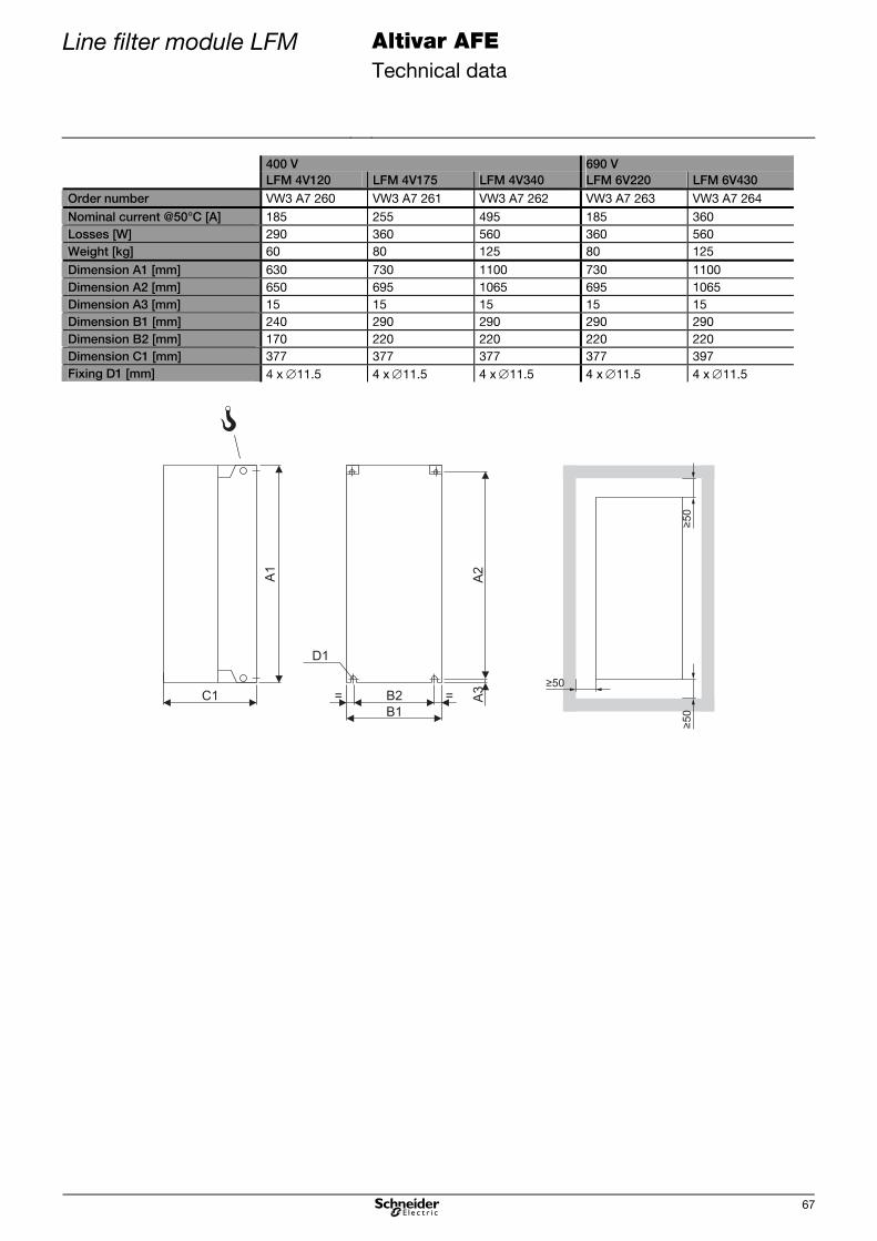
Line filter module LFM Altivar AFE Technical data
67
400 V 690 V LFM 4V120 LFM 4V175 LFM 4V340 LFM 6V220 LFM 6V430 Order number VW3 A7 260 VW3 A7 261 VW3 A7 262 VW3 A7 263 VW3 A7 264
Nominal current @50°C [A] 185 255 495 185 360
Losses [W] 290 360 560 360 560
Weight [kg] 60 80 125 80 125
Dimension A1 [mm] 630 730 1100 730 1100
Dimension A2 [mm] 650 695 1065 695 1065
Dimension A3 [mm] 15 15 15 15 15
Dimension B1 [mm] 240 290 290 290 290
Dimension B2 [mm] 170 220 220 220 220
Dimension C1 [mm] 377 377 377 377 397
Fixing D1 [mm] 4 x 11.5 4 x11.5 4 x11.5 4 x11.5 4 x11.5
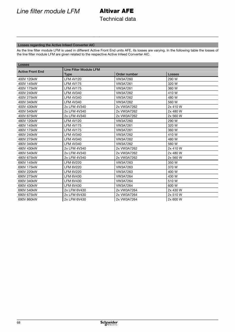
Line filter module LFM Altivar AFE Technical data
68
Losses regarding the Active Infeed Converter AIC
As the line filter module LFM is used in different Active Front End units AFE, its losses are varying. In the following table the losses of
the line filter module LFM are given related to the respective Active Infeed Converter AIC.
Losses Line Filter Module LFM
Active Front End Type Order number Losses
400V 120kW LFM 4V120 VW3A7260 290 W
400V 145kW LFM 4V175 VW3A7261 320 W
400V 175kW LFM 4V175 VW3A7261 360 W
400V 240kW LFM 4V340 VW3A7262 410 W
400V 275kW LFM 4V340 VW3A7262 480 W
400V 340kW LFM 4V340 VW3A7262 560 W
400V 430kW 2x LFM 4V340 2x VW3A7262 2x 410 W
400V 540kW 2x LFM 4V340 2x VW3A7262 2x 480 W
400V 675kW 2x LFM 4V340 2x VW3A7262 2x 560 W
480V 120kW LFM 4V120 VW3A7260 290 W
480V 145kW LFM 4V175 VW3A7261 320 W
480V 175kW LFM 4V175 VW3A7261 360 W
480V 240kW LFM 4V340 VW3A7262 410 W
480V 275kW LFM 4V340 VW3A7262 480 W
480V 340kW LFM 4V340 VW3A7262 560 W
480V 430kW 2x LFM 4V340 2x VW3A7262 2x 410 W
480V 540kW 2x LFM 4V340 2x VW3A7262 2x 480 W
480V 675kW 2x LFM 4V340 2x VW3A7262 2x 560 W
690V 145kW LFM 6V220 VW3A7263 350 W
690V 175kW LFM 6V220 VW3A7263 370 W
690V 220kW LFM 6V220 VW3A7263 400 W
690V 275kW LFM 6V430 VW3A7264 430 W
690V 340kW LFM 6V430 VW3A7264 510 W
690V 430kW LFM 6V430 VW3A7264 600 W
690V 540kW 2x LFM 6V430 2x VW3A7264 2x 430 W
690V 675kW 2x LFM 6V430 2x VW3A7264 2x 510 W
690V 860kW 2x LFM 6V430 2x VW3A7264 2x 600 W

Line filter choke LFC Altivar AFE Technical data
69
Line filter choke LFC
Line filter choke LFC
LFCLFM AIC INV
The line filter choke LFC is an essential component of the Active Front End AFE. It is
connected in the power path between the line filter module LFM and the Active Infeed
Converter AIC and consists of three single-phase chokes.
Line Filter Choke LFC 400 V 500 V / 690 V
General
Nominal voltage 380 V -30 % / 480 V +10 % 500 V -20 % / 690 V +10 %
Design Open constructions for installation into the cubicle
Cooling Natural convection / no forced ventilation
Mechanical strength
Winding protection Drenched in synthetic resin
Mechanical vibration
According to IEC/EN 60068-2-6
1.5 mm in the range of 3...10 Hz, 0.6 g of 10...200 Hz
(3M3 according to IEC/EN 60721-3-3)
Shock
According to IEC/EN 60068-2-27
7 g for 11 ms (3M3 according to IEC/EN 60721-3-3)
Ambient conditions
Operating temperature 45°C, up to +60°C with derating
Storage / Transport
temperature
-25...+70°C
Protection degree IP00
Environmental class /
Humidity
Class 3K3 in accordance with IEC/EN 60721-3-3 / no condensation, max. 95 % relative humidity
Altitude Up to 1000 m, beyond power decrease of 1 %
per 100 m up to 3000 m
Up to 1000 m, beyond power decrease of 1 %
per 100 m up to 2400 m
Standards
Insulation class H
Approvals CE, in preparation: UL, CSA
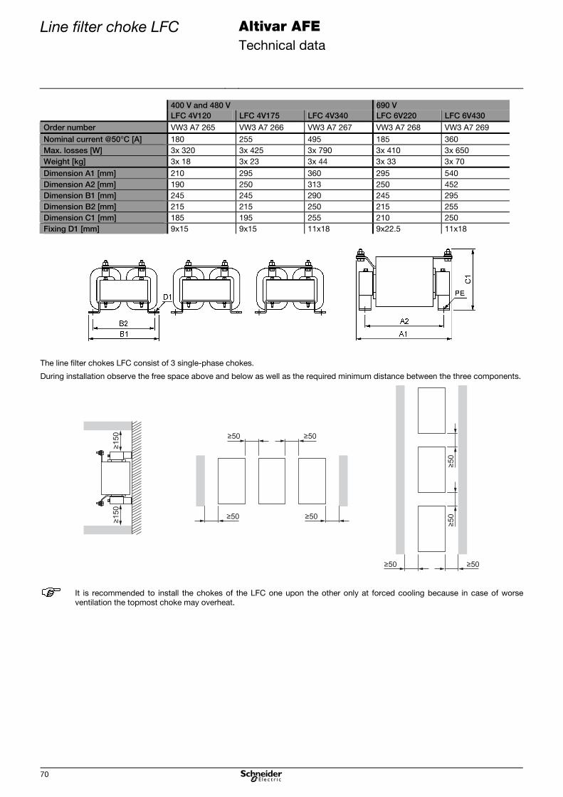
Line filter choke LFC Altivar AFE Technical data
70
400 V and 480 V 690 V LFC 4V120 LFC 4V175 LFC 4V340 LFC 6V220 LFC 6V430 Order number VW3 A7 265 VW3 A7 266 VW3 A7 267 VW3 A7 268 VW3 A7 269
Nominal current @50°C [A] 180 255 495 185 360
Max. losses [W] 3x 320 3x 425 3x 790 3x 410 3x 650
Weight [kg] 3x 18 3x 23 3x 44 3x 33 3x 70
Dimension A1 [mm] 210 295 360 295 540
Dimension A2 [mm] 190 250 313 250 452
Dimension B1 [mm] 245 245 290 245 295
Dimension B2 [mm] 215 215 250 215 255
Dimension C1 [mm] 185 195 255 210 250
Fixing D1 [mm] 9x15 9x15 11x18 9x22.5 11x18
The line filter chokes LFC consist of 3 single-phase chokes.
During installation observe the free space above and below as well as the required minimum distance between the three components.
It is recommended to install the chokes of the LFC one upon the other only at forced cooling because in case of worse
ventilation the topmost choke may overheat.

Line filter choke LFC Altivar AFE Technical data
71
Losses regarding the Active Infeed Converter AIC
As the line filter choke LFC (as the line filter module LFM) is used in different Active Front End units AFE, its losses are varying. In the
following table the losses of the line filter choke LFC are given related to the respective Active Infeed Converter AIC.
Losses Line Filter Choke LFC
Active Front End Type Order number Losses
400V 120kW LFC 4V120 VW3A7265 3x 320 W
400V 145kW LFC 4V175 VW3A7266 3x 370 W
400V 175kW LFC 4V175 VW3A7266 3x 425 W
400V 240kW LFC 4V340 VW3A7267 3x 530 W
400V 275kW LFC 4V340 VW3A7267 3x 620 W
400V 340kW LFC 4V340 VW3A7267 3x 790 W
400V 430kW 2x LFC 4V340 2x VW3A7267 2x (3x 530) W
400V 540kW 2x LFC 4V340 2x VW3A7267 2x (3x 620) W
400V 675kW 2x LFC 4V340 2x VW3A7267 2x (3x 790) W
480V 120kW LFC 4V120 VW3A7265 3x 320 W
480V 145kW LFC 4V175 VW3A7266 3x 370 W
480V 175kW LFC 4V175 VW3A7266 3x 425 W
480V 240kW LFC 4V340 VW3A7267 3x 530 W
480V 275kW LFC 4V340 VW3A7267 3x 620 W
480V 340kW LFC 4V340 VW3A7267 3x 790 W
480V 430kW 2x LFC 4V340 2x VW3A7267 2x (3x 530) W
480V 540kW 2x LFC 4V340 2x VW3A7267 2x (3x 620) W
480V 675kW 2x LFC 4V340 2x VW3A7267 2x (3x 790) W
690V 145kW LFC 6V220 VW3A7268 3x 360 W
690V 175kW LFC 6V220 VW3A7268 3x 380 W
690V 220kW LFC 6V220 VW3A7268 3x 410 W
690V 275kW LFC 6V430 VW3A7269 3x 440 W
690V 340kW LFC 6V430 VW3A7269 3x 540 W
690V 430kW LFC 6V430 VW3A7269 3x 650 W
690V 540kW 2x LFC 6V430 2x VW3A7269 2x (3x 440) W
690V 675kW 2x LFC 6V430 2x VW3A7269 2x (3x 540) W
690V 860kW 2x LFC 6V430 2x VW3A7269 2x (3x 650) W

Active Infeed Converter AIC
Altivar AFE Technical data
72
Active Infeed Converter AIC
Active Infeed Converter AIC
LFCLFM AIC INV
The Active Infeed Converter AIC is connected to the inverter INV via the DC bus. During
operation the energy is supplied to the DC bus or the accumulating braking energy is
feed back into the mains.
Active Infeed Converter AIC 400 V 500 V / 690 V
General
Design Built-in unit for vertical mounting
Cooling Forced
Mechanical strength
Mechanical vibration According to IEC/EN 60068-2-6
1.5 mm in the range of 3...10 Hz, 0.6 g of 10...200 Hz
(3M3 according to IEC/EN 60721-3-3)
Shock According to IEC/EN 60068-2-27
AIC 4V120...AIC 4V175: 7 g for 11 ms
(3M3 according to IEC/EN 60721-3-3)
AIC 4V240...AIC 4V675: 4 g for 11 ms
(3M2 according to IEC/EN 60721-3-3)
AIC 6V145...AIC 6V220: 7 g for 11 ms
(3M3 according to IEC/EN 60721-3-3)
AIC 6V275...AIC 6V860: 4 g for 11 ms
(3M2 according to IEC/EN 60721-3-3)
Ambient conditions
Operating temperature -10...+45°C
(3K3 according to IEC/EN 60721-3-3)
Beyond power decrease of 2 % per 1°C up to +60°C
Storage / Transport temperature -25...+70°C
Protection degree IP00
Environmental class / Humidity Class 3K3 in accordance with IEC/EN 60721-3-3 / no condensation, max. 95 % relative
humidity
Altitude Up to 1000 m, beyond power decrease of 1 %
per 100 m up to 3000 m
Up to 1000 m, beyond power decrease of 1 %
per 100 m up to 2400 m
Allowed pollution Pollution degree 2 according to EN 61800-5-1
3C2 and 3S2 according to EN 60721-3-3
Protection class Class 1 according to EN 61800-5-1
Standards
Basic standard The devices are designed, built and tested on the basis of EN 61800-5-1.
EMC immunity According to EN 61800-3, 1st and 2nd environment
(IEC 1000-4-2; IEC 1000-4-3; IEC 1000-4-4; IEC 1000-4-5; IEC 1000-4-6)
EMC emission In accordance with product standard EN 61800-3, 2nd environment, category C3
Insulation Galvanic insulation from the control electronics in accordance with EN 61800-5-1 PELV
(Protective Extra Low Voltage)
Approvals CE, in preparation: UL, CSA

Active Infeed Converter AIC
Altivar AFE Technical data
73
AIC 4V120 4V145 4V175 Order number VW3 A7 250 VW3 A7 251 VW3 A7 252
Nominal data Input voltage
VN [V] 380 V -30% ...
480 V +10%
380 V -30% ...
480 V +10%
380 V -30% ...
480 V +10%
Input current
IN [A] VN = 400 V 177 212 255
IN [A] VN = 480 V 160 200 200
Input power
PN 400 [kW] VN = 400 V 123 146 175
PN 480 [kW] VN = 480 V 133 166 166
Characteristics
Losses [W] at IN 2250 2660 2970
Losses control part [W] 270 300 360
Losses power part [W] 1980 2360 2610
Weight approx. [kg] 60 74 80
Ambient conditions Volume of cooling air IP23
[m3/h]
400 600 600
Volume of cooling air IP54
[m3/h]
115 145 165
Min. air inflow and air outlet
(IP23) [dm²]
5 7 7
Dimensions Dimension A1 [mm] 680 782 950
Dimension A2 [mm] 650 758 920
Dimension A3 [mm] 15 12 15
Dimension B1 [mm] 310 350 330
Dimension B2 [mm] 250 298 285
Dimension C1 [mm] 377 377 377
Fixing D1 [mm] 4x 11.5 4x 11.5 4x 11.5
If the devices are installed without any
free space sideways, higher minimum
distances are required for sufficient
cooling (values in brackets).
In either case avoid air short circuits.
Basic device without or with 1 option card
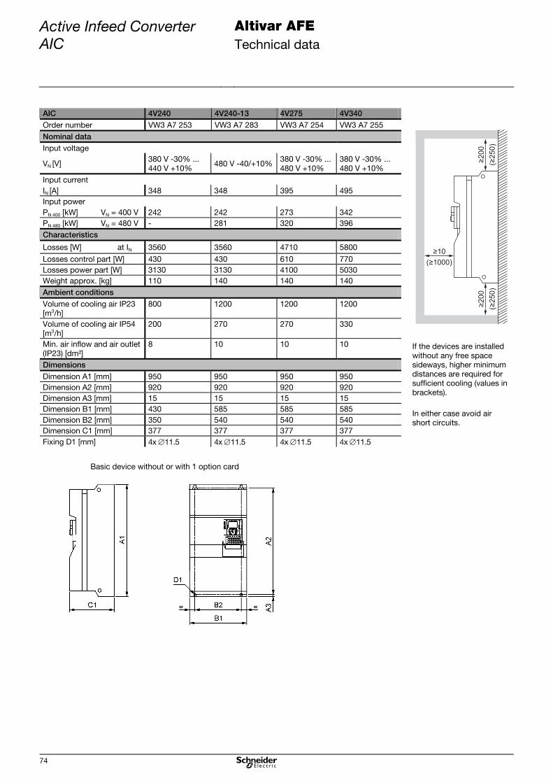
Active Infeed Converter AIC
Altivar AFE Technical data
74
AIC 4V240 4V240-13 4V275 4V340 Order number VW3 A7 253 VW3 A7 283 VW3 A7 254 VW3 A7 255
Nominal data Input voltage
VN [V] 380 V -30% ...
440 V +10% 480 V -40/+10%
380 V -30% ...
480 V +10%
380 V -30% ...
480 V +10%
Input current
IN [A] 348 348 395 495
Input power
PN 400 [kW] VN = 400 V 242 242 273 342
PN 480 [kW] VN = 480 V - 281 320 396
Characteristics
Losses [W] at IN 3560 3560 4710 5800
Losses control part [W] 430 430 610 770
Losses power part [W] 3130 3130 4100 5030
Weight approx. [kg] 110 140 140 140
Ambient conditions Volume of cooling air IP23
[m3/h]
800 1200 1200 1200
Volume of cooling air IP54
[m3/h]
200 270 270 330
Min. air inflow and air outlet
(IP23) [dm²]
8 10 10 10
Dimensions Dimension A1 [mm] 950 950 950 950
Dimension A2 [mm] 920 920 920 920
Dimension A3 [mm] 15 15 15 15
Dimension B1 [mm] 430 585 585 585
Dimension B2 [mm] 350 540 540 540
Dimension C1 [mm] 377 377 377 377
Fixing D1 [mm] 4x 11.5 4x 11.5 4x 11.5 4x 11.5
≥2
00
≥10
( 1000)≥
(2
50
)≥
≥2
00
(2
50
)≥
If the devices are installed
without any free space
sideways, higher minimum
distances are required for
sufficient cooling (values in
brackets).
In either case avoid air
short circuits.
Basic device without or with 1 option card

Active Infeed Converter AIC
Altivar AFE Technical data
75
AIC 4V430 4V430-15 4V540 4V540-15 4V675 Order number VW3 A7 256 VW3 A7 286 VW3 A7 257 VW3 A7 287 VW3 A7 258
Nominal data Input voltage
VN [V] 380 V -30% ...
440 V +10% 480 V -40/+10%
380 V -30% ...
440 V +10% 480 V -40/+10%
380 V -30% ...
440 V +10%
Input current
IN [A] 628 628 780 780 980
Input power
PN 400 [kW] VN = 400 V 431 431 539 539 676
PN 480 [kW] VN = 480 V - 496 - 619 781
Characteristics
Losses [W] at IN 6130 6130 8920 8920 11060
Losses control part [W] 860 860 1190 1190 1500
Losses power part [W] 5270 5270 7730 7730 9560
Weight approx. [kg] 215 300 225 300 300
Ambient conditions Volume of cooling air IP23
[m3/h]
1800 2400 1800 2400 2400
Volume of cooling air IP54
[m3/h]
450 660 500 660 660
Min. air inflow and air outlet
(IP23) [dm²]
15 20 15 20 20
Dimensions Dimension A1 [mm] 1150 1150 1150 1150 1150
Dimension A2 [mm] 1120 1120 1120 1120 1120
Dimension A3 [mm] 15 15 15 15 15
Dimension B1 [mm] 880 1110 880 1110 1110
Dimension B2 [mm] 417.5 533 417.5 533 533
Dimension C1 [mm] 377 377 377 377 377
Fixing D1 [mm] 5x 11.5 6x 11.5 5x 11.5 6x 11.5 6x 11.5
Basic device without or with 1 option card
If the devices are installed
without any free space
sideways, higher minimum
distances are required for
sufficient cooling (values in
brackets).
In either case avoid air short
circuits.
≥250
≥10
( 1000)≥
(300)
≥
≥250
(300)
≥

Active Infeed Converter AIC
Altivar AFE Technical data
76
AIC 6V145 6V175 6V220 Order number VW3 A7 270 VW3 A7 271 VW3 A7 272
Nominal data Input voltage
VN [V] 500V -20% ...
690V +10%
500V -20% ...
690V +10%
500V -20% ...
690V +10%
Input current
IN [A] 120 150 185 (160)1)
Input power
PN 400 [kW] VN = 500 V 104 130 160
PN 480 [kW] VN = 600 V 125 156 166
PN 480 [kW] VN = 690 V 144 175 218
Characteristics Losses [W] at IN 2200 2630 3220
Losses control part [W] 190 220 250
Losses power part [W] 2010 2410 2970
Weight approx. [kg] 110 110 110
Ambient conditions Volume of cooling air IP23
[m3/h]
600 600 600
Volume of cooling air IP54
[m3/h]
190 220 250
Min. air inflow and air outlet
(IP23) [dm²]
7 7 7
Dimensions Dimension A1 [mm] 950 950 950
Dimension A2 [mm] 920 920 920
Dimension A3 [mm] 15 15 15
Dimension A4 [mm] 1190 1190 1190
Dimension B1 [mm] 330 330 330
Dimension B2 [mm] 285 285 285
Dimension B3 [mm] 340 340 340
Dimension C1 [mm] 377 377 377
Fixing D1 [mm] 4x 11.5 4x 11.5 4x 11.5
If the devices are installed without any
free space sideways, higher minimum
distances are required for sufficient
cooling (values in brackets).
In either case avoid air short circuits.
1) only at 600 V
Basic device without or with 1 option card

Active Infeed Converter AIC
Altivar AFE Technical data
77
AIC 6V275 6V340 6V430 Order number VW3 A7 273 VW3 A7 274 VW3 A7 275
Nominal data Input voltage
VN [V] 500V -20% ...
690V +10%
500V -20% ...
690V +10%
500V -20% ...
690V +10%
Input current
IN [A] 228 285 360
Input power
PN 400 [kW] VN = 500 V 198 247 312
PN 480 [kW] VN = 600 V 235 295 371
PN 480 [kW] VN = 690 V 272 340 430
Characteristics Losses [W] at IN 4130 5050 6040
Losses control part [W] 330 380 440
Losses power part [W] 3800 4670 5600
Weight approx. [kg] 190 190 190
Ambient conditions Volume of cooling air IP23
[m3/h]
1200 1200 1200
Volume of cooling air IP54
[m3/h]
160 180 200
Min. air inflow and air outlet
(IP23) [dm²]
10 10 10
Dimensions Dimension A1 [mm] 950 950 950
Dimension A2 [mm] 920 920 920
Dimension A3 [mm] 15 15 15
Dimension A4 [mm] 1190 1190 1190
Dimension B1 [mm] 585 585 585
Dimension B2 [mm] 540 540 540
Dimension B3 [mm] 595 595 595
Dimension C1 [mm] 377 377 377
Fixing D1 [mm] 4x 11.5 4x 11.5 4x 11.5
≥2
00
≥10
( 1000)≥
(2
50
)≥
≥2
00
(2
50
)≥
If the devices are installed without any
free space sideways, higher minimum
distances are required for sufficient
cooling (values in brackets).
In either case avoid air short circuits.
Basic device without or with 1 option card

Active Infeed Converter AIC
Altivar AFE Technical data
78
AIC 6V540 6V675 6V860 Order number VW3 A7 276 VW3 A7 277 VW3 A7 278
Nominal data Input voltage
VN [V] 500V -20% ...
690V +10%
500V -20% ...
690V +10%
500V -20% ...
690V +10%
Input current
IN [A] 450 563 715
Input power
PN 400 [kW] VN = 500 V 390 488 619
PN 480 [kW] VN = 600 V 468 585 742
PN 480 [kW] VN = 690 V 536 673 854
Characteristics Losses [W] at IN 7730 9560 11980
Losses control part [W] 580 690 860
Losses power part [W] 7150 8870 11120
Weight approx. [kg] 400 400 400
Ambient conditions Volume of cooling air IP23
[m3/h]
2400 2400 2400
Volume of cooling air IP54
[m3/h]
260 300 400
Min. air inflow and air outlet
(IP23) [dm²]
20 20 20
Dimensions Dimension A1 [mm] 1150 1150 1150
Dimension A2 [mm] 1120 1120 1120
Dimension A3 [mm] 15 15 15
Dimension A4 [mm] 1390 1390 1390
Dimension B1 [mm] 1110 1110 1110
Dimension B2 [mm] 532.5 532.5 532.5
Dimension B3 [mm] 1120 1120 1120
Dimension C1 [mm] 377 377 377
Fixing D1 [mm] 6x 11.5 6x 11.5 6x 11.5
≥250
≥10
( 1000)≥
(300)
≥
≥250
(300)
≥
If the devices are installed without any
free space sideways, higher minimum
distances are required for sufficient
cooling (values in brackets).
In either case avoid air short circuits.
Basic device without or with 1 option card

Fuses and cable cross sections
Altivar AFE Technical data
79
Fuses and cable cross sections
The Active Front End is equipped with comprehensive protective devices.
It is absolutely necessary to protect the mains side of the whole Active Front End AFE with superfast (semiconductor) fuses
additionally as secondary protection. This protects the individual components in case of an internal short-circuit or if the electronic
protective mechanisms fail. It is also a precondition for operation at mains with high short-circuit power.
The protection at the DC output side is only required in case of connection variant "Active Front End units parallel". When selecting
the fuses, pay attention to the nominal voltage of the fuses and their special qualification to switch-off DC currents.
The mentioned diameters for 3-wire cables are recommended values for laying the cable in air at max. 40°C ambient temperature,
based on the regulations ÖVN EN 1 and VDE 0100.
The lines in the cubicles are dimensioned according to the specification for single conductors XLPE/EPR copper 90°C.
In case of other ambient conditions and different regulations the cable diameters must be adjusted.
Mains supply 3AC 400…440 V AFE DC output
Pre- or conduit fuses
Cu cable [mm²]
Mains fuse "AFE protection"
Lines in the cubicle [mm²] (per phase)
Continuous current AC [A]
Connection LFM
Type Continuous current DC
Connection AIC
Cable for DC connection (per pole) [mm²]
250 A 3x120 250 A sf 95 177 A 1 x M10 120 185 A 1 x M12 95
315 A 3x185 315 A sf 120 212 A 1 x M10 145 220 A 1 x M12 120
400 A 2x (3x120) 350 A sf 150 255 A 1 x M10 175 265 A 1 x M12 150
500 A 2x (3x150) 500 A sf 2x95 348 A 1 x M10 240 366 A 1 x M12 2x95
630 A 2x (3x185) 550 A sf 2x95 395 A 1 x M10 275 412 A 2 x M12 2x95
800 A 3x (3x185) 700 A sf 2x150 495 A 1 x M10 340 517 A 2 x M12 2x150
450 A sf 2x95 314 A 1 x M10 1000 A 4x (3x185)
450 A sf 2x95 314 A 1 x M10
430 654 A 4 x M12 4x95
550 A sf 2x95 390 A 1 x M10 1250 A 4x (3x240)
550 A sf 2x95 390 A 1 x M10
540 815 A 4 x M12 4x120
700 A sf 2x150 490 A 1 x M10 1600 A 6x (3x240)
700 A sf 2x150 490 A 1 x M10
675 1023 A 4 x M12 4x185
Mains supply 3AC 480 V AFE DC output Circuit breaker Rated current
Cu cable [mm²]
Mains fuse "AFE protection"
Lines in the cubicle [mm²] (per phase)
Continuous current AC [A]
Connection LFM Type Continuous
current DC Connection AIC
Cable for DC connection (per pole)
250 1x
(3x250 MCM)
250 A sf AWG 1/0 160 A 1 x M10 120 163 A 1 x M12 AWG 1/0
250 1x
(3x 350 MCM)
315 A sf AWG 3/0 200 A 1 x M10 145 203 A 1 x M12 AWG 3/0
400 2x
(3x AWG 4/0)
350 A sf AWG 4/0 200 A 1 x M10 175 203 A 1 x M12 AWG 4/0
400 2x
(3x350 MCM)
500 A sf 300 MCM 348 A 1 x M10 240 366 A 1 x M12 350 MCM
600 2x
(3x 400 MCM)
550 A sf 350 MCM 395 A 1 x M10 275 412 A 2 x M12 400 MCM or
2x AWG 4/0
600 2x
(3x 400 MCM)
700 A sf 2x 250 MCM 495 A 1 x M10 340 517 A 2 x M12 2x 300 MCM
500 A sf *) 300 MCM 314 A 1 x M10 800 5x
(3x 400 MCM) 500 A sf *) 300 MCM 314 A 1 x M10
430 654 A 4 x M12 2x 400 MCM
550 A sf *) 350 MCM 390 A 1 x M10 1000 6x
(3x 500 MCM) 550 A sf *) 350 MCM 390 A 1 x M10
540 815 A 4 x M12 2x 600 MCM or
3x 350 MCM
700 A sf *) 2x 250 MCM 490 A 1 x M10 1200 6x
(3x 700 MCM) 700 A sf *) 2x 250 MCM 490 A 1 x M10
675 1023 A 4 x M12 3x 500 MCM
*) Parallel connection of 2 LFM and 2 LFC

Fuses and cable cross sections
Altivar AFE Technical data
80
Mains supply 3AC 500/690 V AFE DC output
Pre- or conduit fuse
Cu cable [mm²]
Mains fuse "AFE protection"
Lines in the cubicle [mm²] (per phase)
Continuous current AC [A]
Connection LFM Type Continuous
current DC Connection AIC
Cable for DC connection (per pole) [mm²]
200 A 3x95 160 A sf 50 120 A 1 x M10 145 130 A 1 x M12 50
250 A 3x120 200 A sf 70 150 A 1 x M10 175 156 A 1 x M12 70
315 A 3x185 250 A sf 95 185 A 1 x M10 240 195 A 1 x M12 95
400 A 2x (3x120) 315 A sf 120 228 A 1 x M10 275 244 A 2 x M12 120
400 A 2x (3x120) 400 A sf 150 285 A 1 x M10 340 305 A 2 x M12 150
500 A 2x (3x150) 500 A sf 2x 95 360 A 1 x M10 430 386 A 2 x M12 2x 95
315 A sf *) 120 225 A 1 x M10 800 A 3x (3x185)
315 A sf *) 120 225 A 1 x M10
540 481 A 4 x M12 2x 120
400 A sf *) 150 282 A 1 x M10 800 A 3x (3x185)
400 A sf *) 150 282 A 1 x M10
675 604 A 4 x M12 2x 150
500 A sf *) 2x 95 358 A 1 x M10 1000 A 4x (3x185)
500 A sf *) 2x 95 358 A 1 x M10
860 765 A 4 x M12 3x 150
Mains supply 3AC 600 V AFE DC output Circuit breaker Rated current
Cu cable [mm²]
Mains fuse "AFE protection"
Lines in the cubicle [mm²] (per phase)
Continuous current AC [A]
Connection LFM Type Continuous
current DC Connection AIC
Cable for DC connection (per pole)
160 1x
(3x AWG 2/0)
160 A sf AWG 2 120 A 1 x M10 145 130 A 1 x M12 AWG 2
250 1x
(3x AWG 4/0)
200 A sf AWG 1/0 150 A 1 x M10 175 156 A 1 x M12 AWG 1/0
250 1x
(3x 300 MCM)
250 A sf AWG 2/0 160 A 1 x M10 240 170 A 1 x M12 AWG 2/0
400 1x
(3x 400 MCM)
315 A sf AWG 3/0 228 A 1 x M10 275 244 A 2 x M12 AWG 3/0
400 2x
(3x 250 MCM)
400 A sf AWG 4/0 285 A 1 x M10 340 305 A 2 x M12 250 MCM
600 2x
(3x 350 MCM)
500 A sf 350 MCM 360 A 1 x M10 430 386 A 2 x M12 350 MCM
315 A sf *) AWG 3/0 225 A 1 x M10 600 3x
(3x 350 MCM) 315 A sf *) AWG 3/0 225 A 1 x M10
540 481 A 4 x M12 500 MCM or 2x250
MCM
400 A sf *) AWG 4/0 282 A 1 x M10 800 3x
(3x 500 MCM) 400 A sf *) AWG 4/0 282 A 1 x M10
675 604 A 4 x M12 2x350 MCM
500 A sf *) 350 MCM 358 A 1 x M10 1000 6x
(3x 400 MCM) 500 A sf *) 350 MCM 358 A 1 x M10
860 765 A 4 x M12 3x350 MCM
*) Parallel connection of 2 LFM and 2 LFC
As mains fuses for protection of the AFE superfast (semiconductor) fuses have to be used.
If the mains fuses blow the Active Front End already has a primary defect. Therefore, exchanging the blown fuses and
switching the Active Front End on again is not effective.
In order to meet the requirements of UL/CSA, copper cables with temperature class 60/70°C have to be used.
In order to meet the requirements of UL/CSA, a listed circuit breaker has to be used.

Fuses and cable cross sections
Altivar AFE Technical data
81
Recommended mains fuses
Types of mains fuses for 400 V – 440 V mains
Recommended type of fuse AFE Type 400V-440V
Mains fuse Ferraz Shawmut, Protistor semiconductor fuse, PSC aR sizes 3x – 690/700Vac
Bussmann High speed fuse square body flush end contact – 690/700Vac
120 250 A 6.9 URD 30 TTF 0250 170M3416
145 315 A 6.9 URD 30 TTF 0315 170M3417
175 350 A 6.9 URD 30 TTF 0350 170M3418
240 500 A 6.9 URD 30 TTF 0500 170M3421
275 550 A 6.9 URD 30 TTF 0550 170M3422
340 700 A 6.9 URD 31 TTF 0700 170M4417
430 2x450 2x 6.9 URD 30 TTF 0450 2x 170M3420
540 2x550 2x 6.9 URD 30 TTF 0550 2x 170M3422
675 2x700 2x 6.9 URD 31 TTF 0700 2x 170M4417
Types of mains fuses for 480 V mains (UL)
Recommended type of fuse AFE Type 480V
Mains fuse Ferraz Shawmut, Protistor semiconductor fuse, PSC aR sizes 3x – 690/700Vac
Bussmann High speed fuse square body flush end contact – 690/700Vac
120 250 A A070 URD 30 TTI 0250 170M3416
145 315 A A070 URD 30 TTI 0315 170M3417
175 350 A A070 URD 30 TTI 0350 170M3418
240 500 A A070 URD 30 TTI 0500 170M3421
275 550 A A070 URD 30 TTI 0550 170M3422
340 700 A A070 URD 32 TTI 0700 170M4417
430 2x450 2x A070 URD 30 TTI 0450 2x 170M3421
540 2x550 2x A070 URD 30 TTI 0550 2x 170M3422
675 2x700 2x A070 URD 32 TTI 0700 2x 170M4417
Types of mains fuses for 500 V / 690 V mains
Recommended type of fuse AFE Type 500V / 690V
Mains fuse Ferraz Shawmut, Protistor semiconductor fuse, PSC aR sizes 3x – 690/700Vac
Bussmann High speed fuse square body flush end contact – 690/700Vac
145 160 A 6.9 URD 30 TTF 0160 170M3414
175 200 A 6.9 URD 30 TTF 0200 170M3415
220 250 A 6.9 URD 30 TTF 0250 170M3416
275 315 A 6.9 URD 30 TTF 0315 170M3417
340 400 A 6.9 URD 30 TTF 0400 170M3419
430 500 A 6.9 URD 30 TTF 0500 170M3421
540 2x315 2x 6.9 URD 30 TTF 0315 2x 170M3417
675 2x400 2x 6.9 URD 30 TTF 0400 2x 170M3419
860 2x500 2x 6.9 URD 30 TTF 0500 2x 170M3421

Fuses and cable cross sections
Altivar AFE Technical data
82
Types of mains fuses for 600 V mains (UL/CSA)
Recommended type of fuse AFE Type 500V / 690V
Mains fuse Ferraz Shawmut, Protistor semiconductor fuse, PSC aR sizes 3x – 690/700Vac
Bussmann High speed fuse square body flush end contact – 690/700Vac
145 160 A A070 URD 30 TTI 0160 170M3414
175 200 A A070 URD 30 TTI 0200 170M3415
220 250 A A070 URD 30 TTI 0250 170M3416
275 315 A A070 URD 30 TTI 0315 170M3417
340 400 A A070 URD 30 TTI 0400 170M3419
430 500 A A070 URD 32 TTI 0500 170M3421
540 2x315 2x A070 URD 30 TTI 0315 2x 170M3417
675 2x400 2x A070 URD 30 TTI 0400 2x 170M3419
860 2x500 2x A070 URD 32 TTI 0500 2x 170M3421
Generally also other models and types of fuses can be used provided that their electrical data are comparable.
In order to meet the requirements of UL/CSA, the specified fuse types have to be used.

Cubicle installation Altivar AFE Technical data
83
Cubicle installation
Cubicle installation IP23 Line Filter Module LFM
As the line filter module does not include an internal fan, it is necessary to
provide a fan in the door of the cubicle for exhaust. This prevents heat
accumulation and it also provides cooling of the Line Filter Choke LFC. The air
flow must not be constrained by means of fixtures or filter mats. The air flow
has to be determined regarding the ambient conditions and the losses in the
Line Filter Module LFM and Line Filter Choke LFC.
1. Line Filter Module LFM
2. Fan (without filter mat for IP23, with filter mat for IP54)
3. Line Filter Choke LFC
4. Air inlet grid (without filter mat for IP23, with filter mat for IP54)
Active Infeed Converter AIC
The illustration besides shows the typical cubicle design in protection degree
IP23. The stated losses and minimum cross sections for air inlet are related to
the Active Infeed Converter AIC. Further heat sources like fuses and
contactors must be considered additionally. The fan of the power part, which
is inside the device, provides the exhaust of the enclosure. The air flow must
not be constrained by means of fixtures or filter mats. Provide a separation of
the power part air to avoid internal air short-cuts.
1. Active Infeed Converter AIC
2. Air guide or transformer
3. Line Filter Choke LFC
4. Air inlet grid (without filter mat)
5. Metal cover with splash water protection
6. Separation wall to avoid internal air short-cuts
7. DC bus
A design with higher protection degrees (e.g. IP54) is possible on the
basis of the inverters INV.

Cubicle installation Altivar AFE Technical data
84
Exhaust concept for cubicle installation The components of the Active Front End AFE are designed in protection class
IP00 and thus they are intended for cubicle installation.
The following illustrations show the recommended installation of the individual
components into the cubicle. In order to avoid air short-cuts, it is necessary to
install a suitable air guide above the Active Infeed Converter AIC. The losses of
the line filter module LFM must be exhausted by means of filter fans in the
cubicle door.
AFE 400V to 175kW
AFE 480V to 175kW
AFE 690V to 220kW
LFC
LFC LFC
LFM
AMF
AIC INV
U WVL1 L3L2
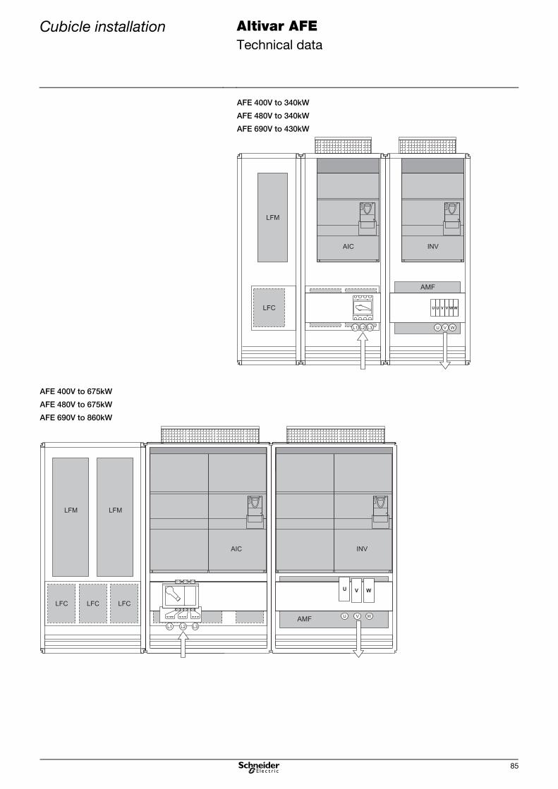
Cubicle installation Altivar AFE Technical data
85
AFE 400V to 340kW
AFE 480V to 340kW
AFE 690V to 430kW
LFC LFC
LFM
AIC
LFC V W WU U V
U WVL1 L3L2
AMF
INV
AFE 400V to 675kW
AFE 480V to 675kW
AFE 690V to 860kW
LFC LFC LFCLFC LFC LFC
LFMLFM
INVAIC
AMF
WVU

Overview Altivar AFE Options
86
Options
Overview
Operating and control options Option Brief description Order number Weight
[kg] Reference
Operating options Remote mounting kit Enables the installation of the graphic display terminal
in the cubicle door (protection degree IP54).
VW3 A1 102 0.150 See
product
catalogue
IP65 transparent cover Transparent IP65 cover for the door mounting kit of the
operating panel
VW3 A1 103 0.040 See
product
catalogue
Pre-assembled RJ45 connecting cable 1 m VW3 A1 104 R10 0.050 See
product
catalogue
Pre-assembled RJ45 connecting cable 3 m VW3 A1 104 R30 0.150 See
product
catalogue
Pre-assembled RJ45 connecting cable 5 m VW3 A1 104 R50 0.250 See
product
catalogue
Connecting cable for
decentralised
installation of the
graphic display terminal
Pre-assembled RJ45 connecting cable 10 m VW3 A1 104 R100 0.500 See
product
catalogue
RJ45 adapter socket RJ45 F/F adapter is required for the connection of the
operating panel to the connecting cable
VW3 A1 105
0.010 See
product
catalogue
Control options Basic I/O options card Terminal extension for additional logic inputs and
outputs
VW3 A3 201 0.320 See
product
catalogue
Option card
"Communication
bridge"
Option card for communication with other fieldbus
systems
(only useful for the inverter INV)
on request 0.320 Page 88
Wiring options Fan wiring 6V Option for connecting the fans at 690V devices.
This option is only necessary for the inverters.
1x for ATV61HC11Y...C40Y; ATV71HC11Y...C31Y
2x for ATV61HC50Y...C80Y; ATV71HC40Y...C63Y
VW3 A7 280 0.320 Page 89

Overview Altivar AFE Options
87
Fieldbus options Option Brief description Order number Weight
[kg] Reference
Modbus Modbus splitter Divides the Modbus signal into eight additional
channels using a star configuration. Several Modbus
splitters can be connected parallel.
LU9 GC3 0.500 See product
catalogue
Modbus T-adapter with 0.3 m connecting cable VW3 A8 306 TF03 0.190 See product
catalogue
Modbus T-adapter
Modbus T-adapter with 1 m connecting cable VW3 A8 306 TF10 0.210 See product
catalogue
Pre-assembled RJ45 connecting cable 0.3 m VW3 A8 306 R03 0.025 See product
catalogue
Pre-assembled RJ45 connecting cable 1 m VW3 A8 306 R10 0.060 See product
catalogue
Connecting cable
Pre-assembled RJ45 connecting cable 3 m VW3 A8 306 R30 0.130 See product
catalogue
Bus termination Bus termination RC VW3 A8 306 RC 0.010 See product
catalogue
CANopen CANopen adapter RJ45/Sub-D adapter for connecting the Active Front
End to a CANopen fieldbus system.
VW3 CAN A71 See product
catalogue
Plug connector Connecting plug for CANopen fieldbus system VW3 CAN KCDF 180T See product
catalogue
Pre-assembled standard connecting cable 50 m
minimal smoke emission, non-halogen
self-extinguishing (IEC 60332-1)
TSX CAN CA 50 4.930 See product
catalogue
Pre-assembled standard connecting cable 100 m
minimal smoke emission, non-halogen
self-extinguishing (IEC 60332-1)
TSX CAN CA 100 8.800 See product
catalogue
Standard connecting
cable
Pre-assembled standard connecting cable 300 m
minimal smoke emission, non-halogen
self-extinguishing (IEC 60332-1)
TSX CAN CA 300 24.560 See product
catalogue
Pre-assembled UL connecting cable 50 m
self-extinguishing (IEC 60332-2)
TSX CAN CB 50 3.580 See product
catalogue
Pre-assembled UL connecting cable 100 m
self-extinguishing (IEC 60332-2)
TSX CAN CB 100 7.840 See product
catalogue
UL connecting cable
Pre-assembled UL connecting cable 300 m
self-extinguishing (IEC 60332-2)
TSX CAN CB 300 21.870 See product
catalogue
Pre-assembled connecting cable 50 m
for difficult ambient conditions or mobile installation.
Minimal smoke emission, non-halogen
self-extinguishing (IEC 60332-1)
TSX CAN CD 50 3.510 See product
catalogue
Pre-assembled connecting cable 100 m
for difficult ambient conditions or mobile installation.
Minimal smoke emission, non-halogen
self-extinguishing (IEC 60332-1)
TSX CAN CD 100 7.770 See product
catalogue
Connecting cable
for difficult environment
Pre-assembled connecting cable 300 m
for difficult ambient conditions or mobile installation.
Minimal smoke emission, non-halogen
self-extinguishing (IEC 60332-1)
TSX CAN CD 300 21.700 See product
catalogue

Control options Altivar AFE Options
88
Control options
Option card "Communication bridge" Description
The option card "Communication bridge" enables indirect connection of the
Active Front End AFE to further fieldbus systems.
This option card serves as compiler between two fieldbus systems. It is
installed together with a fieldbus card in an inverter INV. By means of this
combination it is possible to address the inverter as well as up to 4 Active
Front End units AFE.
The communication between the option card "AFE COMM-Bridge" and the
Active Front End unit(s) takes place via CANopen.
Application
L1
L2
L3
1L1
1L2
1L3
Q1
3L3
3L2
3L1
PA/+
PC/-
LFM AICPA/+
PC/-
INV
W
V
U
M
2L1
2L2
2L3
1
1
1
2
2
2
LFC
24V 24V
1.)
PWR
Control part
Active Front End AFE
Control part
Message"Run"(AFE + INV)
EmergencyOFF
Control andmonitoring
AFE via CANopen
Option
field
bus
Message"Run"(AFE)
Option
com
m.b
r.
Fuse
Control and monitoringvia fieldbus
1.) 24V bufferingfor INV
The control and status word of the inverter is used for control and monitoring
of the Active Front End unit(s).
The management of the control and status words has to be realised in the
control system (PLC, ...).
As the option card "AFE COMM-Bridge" can be only used together
with an option card "Fieldbus", there are no further card slots
available at the inverter.

Control options Altivar AFE Options
89
Option "AFE Fan wiring 6V" VW3A7280 Description
The option "AFE Fan wiring 6V" enables simple wiring of the fans in the inverter
INV (at 690 V devices).
For the 690 V devices the fans are supplied via the transformer box at the top
side of the devices. The fans in the inverter INV are supplied from the drive
side between the terminals 4/5/6 in the line filter module LFM and the
transformer box at the top side of the inverter INV.
For fan supply of the inverter(s) INV it is necessary to order the option
"Fan wiring 6V" with reference number VW3A7280.
1x VW3A7280 for ATV61HC11Y...C40Y; ATV71HC11Y...C31Y
2x VW3A7280 for ATV61HC50Y...C80Y; ATV71HC40Y...C63Y
Application
To wire the fan supply at the inverters ATV71HC11Y to HC31Y and ATV61HC11Y to HC40Y respectively option "Fan wiring 6V"
(VW3 A7 280) has to be ordered once.
W1
LFM
AIC ... X1: 1/2/3INV ... X1: 4/5/6
X3
0
W1
LFM
AIC ... X1: 1/2/3INV ... X1: 4/5/6
X3
0
To wire the fan supply at the inverters ATV71HC40Y to HC63Y and ATV61HC50Y to HC80Y respectively option "Fan wiring 6V"
(VW3 A7 280) has to be ordered twice.
W1
LFM
AIC ... X1: 1/2/3INV ... X1: 4/5/6
X30
X30
As the option card "AFE COMM-Bridge" can be only used together with an option card "Fieldbus", there are no further card
slots available at the inverter.

Options depending on the power
Altivar AFE Options
90
Options depending on the power
Radio frequency interference filter RFI
The Active Front End units include a radio frequency interference filter for use
in industrial environments according to EN 61800-3 category C3 as standard.
For applications in "1st environment - residential environments" of category C2,
when several inverters INV are operated at the DC bus and in case of long
motor cables, the use of the additional RFI filters is required. These filters are
connected at the mains side of the Active Front End.
The determining factor for the radio frequency interference filters to be
effective is a HF connection as good as possible between motor,
motor cable screen, inverter components, line filter module and filter!
The RFI filters are not qualified for nongrounded (IT) mains as well as
for "Corner Grounded Networks". The radio frequency interference
filter which is built-in as standard can be switched-over/reconnected.
General technical data
Operating voltage RFI 480 3AC 380 V -15 % ... 480 V +10 %
Operating voltage RFI 6V 3AC 500 V -15 % ... 690 V +10 %
Nominal frequency 50/60 Hz 5 %
Overload capability 150 % for 60 s per 10 min, 200 % for 2 s
Ambient temperature -10...+50 °C (up to 60 °C with derating)
Storage temperature -40...+70 °C
Altitude 0...1000 m (up to 3000 m with derating)
Vibration resistance 1.5 mm at 3...13 Hz, 1 g at 13...200 Hz according to IEC/EN 60068-2-6
Shock resistance 15 g for 11 ms according to IEC/EN 60068-2-27
Approvals CE, UR, GOST
Allocation table Description Altivar Order number Weight
[kg] RFI filter 400V 4V120 … 4V175 VW3 A4 410 13.000
4V240 … 4V340 VW3 A4 411 15.000
4V430 … 4V675 2x VW3 A4 411 30.000
RFI filter 690V 6V145 … 6V220 VW3 A4 414 14.000
6V275 … 6V430 VW3 A4 415 18.000
6V540 … 6V860 2x VW3 A4 415 36.000

Options depending on the power
Altivar AFE Options
91
Radio frequency interference filter RFI 480/300-TN RFI 480/600-TN RFI 6V220-TN RFI 6V430-TN Order number VW3 A4 410 VW3 A4 411 VW3 A4 414 VW3 A4 415
Nominal current 300 A 580 A 220 A 430 A
Max. leakage current 350 mA 350 mA 450 mA 450 mA
Cont.leakage current 3 mA 3 mA 5 mA 5 mA
Protection degree IP00, with protection against contact
Losses 60 W 125 W 45 W 90 W
Weight 13 kg 15 kg 14 kg 18 kg
Dimension A1 306 mm 306 mm 306 mm 306 mm
Dimension A2 300 mm 300 mm 300 mm 300 mm
Dimension A3 40 mm 95 mm 40 mm 95 mm
Dimension A4 120 mm 120 mm 120 mm 120 mm
Dimension B1 260 mm 260 mm 260 mm 260 mm
Dimension B2 235 mm 235 mm 235 mm 235 mm
Dimension B3 210 mm 210 mm 210 mm 210 mm
Dimension C1 135 mm 135 mm 135 mm 135 mm
Dimension C2 65 mm 65 mm 65 mm 65 mm
Protective cover L 800 mm 800 mm 800 mm 800 mm
Fixing D1 6 x 12 mm 6 x 12 mm 6 x 12 mm 6 x 12 mm
Connection bar 25 x 6 mm
1 x M10
32 x 8 mm
2 x M10
25 x 6 mm
1 x M10
30 x 8 mm
2 x M10
PE connection M12 M12 M12 M12

Data for the DC bus Altivar AFE Inverter
92
Inverter
Data for the DC bus
LFCLFM AIC INV
Additionally to the single drive it is possible to supply several inverters with an Active
Front End via a common DC link (1:n configuration). Also parallel connection of several
Active Front End units AFE is possible (n:n configuration).
As the total power of the installed inverters may be higher than the nominal power of the
Active Front End, next to the performance record also the maximum possible load
capacity (see tables on page 36 or page 51) of the line filter module LFM has to be
observed when dimensioning the complete configuration.
In the following tables the DC bus power and capacities of the inverters INV are given:
DC bus power demand / capacities Power DC fuse 1)
Inverter INV Type Motor (VT)
[kW] DC (at 400 V) [kW]
DC (at 480 V) [kW]
[A]
DC capacity [mF]
ATV61H 075N4 0.8 1.1 1.2 16 0.2
U15N4 1.5 2.0 2.3 16 0.2
U22N4 2.2 2.8 3.2 16 0.3
U30N4 3.0 3.7 4.3 16 0.4
U40N4 4.0 4.9 5.6 20 0.6
U55N4 5.5 6.6 7.6 25 0.8
U75N4 7.5 8.8 10 32 1.1
D11N4 11 13 15 40 1.4
D15N4 15 17 20 63 1.9
D18N4 18 21 24 63 1.9
D22N4 22 25 29 80 1.4
D30N4 30 34 39 100 2.0
D37N4 37 41 47 125 2.4
D45N4 45 50 58 160 2.7
D55N4 55 60 69 160 3.9
D75N4 75 82 94 200 4.8
D90N4D 90 98 115 250 6.5
C11N4D 110 120 140 250 6.5
C13N4D 130 140 160 315 9.8
C16N4D 160 170 195 350 9.8
C22N4D 220 240 275 500 13
C25N4D 250 270 310 550 14
C31N4D 310 330 380 700 20
C40N4D 400 420 480 2x450 21
C50N4D 500 530 610 2x550 30
C63N4D 630 660 760 2x700 39
ATV61EXA● C63N4 630 660 706 60
C71N4 710 750 783 60
C90N4 900 940 977 120
M11N4 1100 1200 1170 120
1.) For the DC fuse the type "Ferraz Protistor DC fuse gR" is recommended. Otherwise a similar type for 800VDC at 10ms
L/R has to be sued for the DC fuse. (Also see AFE DC fuses)

Data for the DC bus Altivar AFE Inverter
93
DC bus power demand / capacities Power DC fuse 1)
Inverter INV Type Motor (CT)
[kW] DC (at 400 V) [kW]
DC (at 480 V) [kW]
[A]
DC capacity [mF]
ATV71H 075N4 0.8 1.1 1.2 16 0.2
U15N4 1.5 2.0 2.3 16 0.2
U22N4 2.2 2.8 3.2 16 0.3
U30N4 3.0 3.7 4.3 20 0.4
U40N4 4.0 4.9 5.6 25 0.6
U55N4 5.5 6.6 7.6 32 0.8
U75N4 7.5 8.8 10 40 1.1
D11N4 11 13 15 63 1.4
D15N4 15 17 20 63 1.9
D18N4 18 21 24 80 1.9
D22N4 22 25 29 100 1.4
D30N4 30 34 39 125 2.0
D37N4 37 41 47 160 2.4
D45N4 45 50 58 160 2.7
D55N4 55 60 69 200 3.9
D75N4 75 82 94 250 4.8
D90N4 90 98 115 250 6.5
C11N4D 110 120 140 315 9.8
C13N4D 130 140 160 350 9.8
C16N4D 160 170 195 500 13
C20N4D 200 210 240 550 14
C25N4D 250 270 310 700 20
C28N4D 280 300 345 800 20
C31N4D 310 330 380 2x450 21
C40N4D 400 420 485 2x550 30
C50N4D 500 530 610 2x700 39
ATV71EXA● C50N4 500 530 550 60
C63N4 630 660 706 60
C71N4 710 750 784 120
C90N4 900 940 977 120
M11N4 1100 1150 1170 120
1.) For the DC fuse the type "Ferraz Protistor DC fuse gR" is recommended. Otherwise a similar type for 800VDC at 10ms
L/R has to be sued for the DC fuse. (Also see AFE DC fuses)

Data for the DC bus Altivar AFE Inverter
94
DC bus power demand / capacities Power at 500 V Power at 600 V Power at 690 V
Inverter INV Type Motor (VT)
[kW] DC [kW]
Motor (VT) [HP]
DC [kW]
Motor (VT) [kW]
DC [kW]
DC fuse 1)
[A] DC capacity [mF]
ATV61H C11Y 90 100 125 105 110 120 160 3.9
C13Y 110 120 150 120 132 142 160 3.9
C16Y 132 142 180 143 160 172 200 3.9
C20Y 160 172 200 159 200 215 250 3.9
C25Y 200 215 250 199 250 268 315 7.8
C31Y 250 268 350 279 315 335 400 7.8
C40Y 315 335 450 355 400 424 500 7.8
C50Y 400 424 550 431 500 528 630 16
C63Y 500 528 700 547 630 663 800 16
C80Y 630 663 800 624 800 842 1000 16
ATV61EXA● C80Y 630 665 800 630 800 838 31
M10Y 800 842 1000 787 1000 1050 31
M12Y 900 948 1250 981 1200 1250 31
1.) For the DC fuse the type "Ferraz Protistor DC fuse gR" is recommended. Otherwise a similar type for 800VDC at 10ms
L/R has to be sued for the DC fuse. (Also see AFE DC fuses)
DC bus power demand / capacities Power at 500 V Power at 600 V Power at 690 V
Inverter INV Type Motor (CT)
[kW] DC [kW]
Motor (CT) [HP]
DC [kW]
Motor (CT) [kW]
DC [kW]
DC fuse 1)
[A] DC capacity [mF]
ATV71H C11Y 90 100 125 103 110 120 160 3.9
C13Y 110 120 150 120 132 142 200 3.9
C16Y 132 142 180 143 160 172 250 3.9
C20Y 160 172 200 159 200 215 315 7.8
C25Y 200 215 250 199 250 268 400 7.8
C31Y 250 268 350 279 315 335 500 7.8
C40Y 315 335 450 355 400 424 630 16
C50Y 400 424 550 431 500 528 800 16
C63Y 500 528 700 547 630 663 1000 16
ATV71EXA● C63Y 500 529 700 552 630 662 31
C80Y 630 665 800 631 800 838 31
M10Y 800 842 1000 787 1000 1050 31
1.) For the DC fuse the type "Ferraz Protistor DC fuse gR" is recommended. Otherwise a similar type for 800VDC at 10ms
L/R has to be sued for the DC fuse. (Also see AFE DC fuses)

Parameter settings Altivar AFE Inverter
95
Parameter settings
Required settings at the inverter It is absolutely necessary to carry out the following settings for all frequency inverters connected to an Active Front End:
AFE [Regen. connection] in menu [1.7 APPLICATION FUNCT.] (FUn-) in submenu [REGEN. CONNECTION] (OIr-) Setting: [Yes] (YES)
Thereby the undervoltage level of the frequency inverter is adapted to the operation with the Active Front End.
Please contact our service team if this parameter is not available in the parameter list of your device!
brA [Braking balance] in menu [1.7 APPLICATION FUNCT.] (FUn-) in submenu [RAMP TYPE] (rPt-) Setting: [No] (nO)
dEC [Deceleration] in menu [1.7 APPLICATION FUNCT.] (FUn-) in submenu [RAMP TYPE] (rPt-) For dynamic processes a very short deceleration ramp can cause an overload on the DC-bus with an overvoltage fault shut-
down.
This can be prevented by an extension or rounding of the deceleration ramp (parameters tA3 [Begin Dec round]; tA4 [End Dec
round]).
UrES [Mains voltage] in menu [1.8 FAULT MANAGEMENT] (FLt-) in submenu [UNDERVOLTAGE MGT.] (USb-) Same setting as the Active Front End.
Thereby the internal voltage levels of the frequency inverter are adapted.
IPL [Input phase loss] in menu [1.8 FAULT MANAGEMENT] (FLt-) in submenu [INPUT PHASE LOSS] (OPL-) Setting: [Ignore] (nO)
bUb [Brake res. fault Mgt] in menu [1.8 FAULT MANAGEMENT] (FLt-) in submenu [BU PROTECTION] (bUF-) Setting: [Ignore] (nO)
tCt [2 wire type] in menu [1.5 INPUTS/OUTPUTS CFG] (I-O-) Setting: [Level] (LEL)
In order to ensure an automatic restart by the AFE after an undervoltage recognition. An automatic restart only possible with 2-
wire control.
RFI filter The integrated RFI filter has to be deactivated (position IT, non-grounded mains) at all devices because there exists no direct
mains connection of the frequency inverter in case of operation with an Active Front End.
Non-observance of these precautions may cause material damage.
The 24 V control voltage of the Active Front End AFE can also be used to buffer the control electronics of the frequency
inverter.
When the frequency inverter is supplied via the DC link an external supply for the device fans is required!
Via the LFM (line filter module) it is possible to supply the device fans with up to 4 additional inverters (with the same power
as the AIC).

Parameter settings Altivar AFE Inverter
96


Schneider Electric Power Drives GmbH
04 / 20108 P02 513 EN.02/02
Due to evolution of standards and equipment, the characteristics indicated in texts and images of
this document do not constitute a commitment on our part without confirmation.
Design: Schneider Electric Power Drives
Photos: Schneider Electric Power Drives
Ruthnergasse 1
A-1210 Vienna
Phone:
Fax: +43 (0) 1 29191 15
+43 (0) 1 29191 0