Alternating Current
18
1 Physics: Alternating Current Chapter - 7 1. PHASORS Alternating Current A time varying periodic current with constant amplitude which reverses its direction at the end of every half cycle is referred to as alternating current. In its sinusoidal form, it can be represented as follows: The corresponding voltage is called alternating voltage. Most of the electric power is generated and used in the a.c form. Advantages of AC Alternating voltage can be easily increased or decreased by means of transformers. Alternating current energy can be transmitted and distributed over long distances without much loss of energy. Mathematical Representation a.c. is represented as I = I o sin t Or I = I o cos t Where, I is the instantaneous value of current at any instant t, I o is the peak value or maximum value of ac (called amplitude) and is the angular frequency of a.c. Also = 2 π 2π T f Where, T is the time period of a.c. Similarly, a.c. voltage can be represented as, E = E o sin t Or E = E o cos t The effective value of ac is given in terms of its rms value. The rms value of ac is the value of dc that would produce the same amount of heat across a conductor over a given time. For ac in sinusoidal form, the rms value is 1 2 times the peak value. 0 0 I I 0.707 I 2 rms 0 0 I I 0.707 I 2 rms , 0 rms 0 E E 0.707 E 2 Note: For triangular waves, 0 I I 3 rms For square waves, I rms = I 0 The mean value of ac over a full cycle is zero. As a practical measure, the average value is calculated as the mathematical mean of all the points’ absolute values. In sinusoidal form, the average value of ac, so calculated, is approximately 0.637 of its peak value. I av = 0.637 I 0 Phasor Diagrams A phasor is a vector which rotates about the origin with an angular speed . The phasor can be current phasor or voltage phasor. The length of the phasor gives the magnitude of the quantity (i.e. I or E). Phasors are inclined to horizontal axis at an angle equal to ‘t’ and rotates in the anticlockwise direction. Projection of the phasor on any axis represents the instantaneous value of the quantity. In sine form, projection is taken on the vertical axis. In cosine form, projection is taken on the horizontal axis. Phase difference between two alternating quantities is represented by the angle between the two vectors o E and o I The diagram or plot of phasors for analysing an a.c circuit is called phasor diagram.
-
Upload
atul-verma -
Category
Documents
-
view
117 -
download
0
description
vvv
Transcript of Alternating Current

1
Physics: Alternating Current
Chapter - 7
1. PHASORSAlternating Current A time varying periodic current with constant amplitude which reverses its
direction at the end of every half cycle is referred to as alternating current. In its sinusoidal form, it can be represented as follows: The corresponding voltage is called alternating voltage. Most of the electric power is generated and used in the a.c form.Advantages of AC Alternating voltage can be easily increased or decreased by means of
transformers. Alternating current energy can be transmitted and distributed over long
distances without much loss of energy.Mathematical Representationa.c. is represented as
I = Io sin tOr I = Io cos tWhere, I is the instantaneous value of current at any instant t, Io is the peak value or maximum value of ac (calledamplitude) and is the angular frequency of a.c.
Also = 2 π 2πT
f
Where, T is the time period of a.c.Similarly, a.c. voltage can be represented as,E = Eo sin t Or E = Eo cos t
The effective value of ac is given in terms of itsrms value. The rms value of ac is the value of dcthat would produce the same amount of heat
across a conductor over a given time. For ac in sinusoidal form, the rms value is 12
times the peak value.
00
II 0.707 I
2rms
00
II 0.707 I
2rms , 0rms 0
EE 0.707 E
2
Note: For triangular waves, 0II
3rms For square waves, Irms = I0
The mean value of ac over a full cycle is zero. As a practical measure, the average value is calculated as themathematical mean of all the points’ absolute values. In sinusoidal form, the average value of ac, so calculated, isapproximately 0.637 of its peak value.Iav = 0.637 I0
Phasor Diagrams A phasor is a vector which rotates about the origin with an angular speed . The phasor can be current phasor or voltage phasor. The length of the phasor gives the magnitude of the quantity (i.e. I or E). Phasors are inclined to horizontal axis at an angle equal to ‘t’ and rotates in the anticlockwise direction. Projection of the phasor on any axis represents the instantaneous value of the quantity. In sine form, projection is taken on the vertical axis. In cosine form, projection is taken on the horizontal axis.
Phase difference between two alternating quantities is represented by the angle between the two vectors oE
and oI
The diagram or plot of phasors for analysing an a.c circuit is called phasor diagram.
2
Physics: Alternating Current
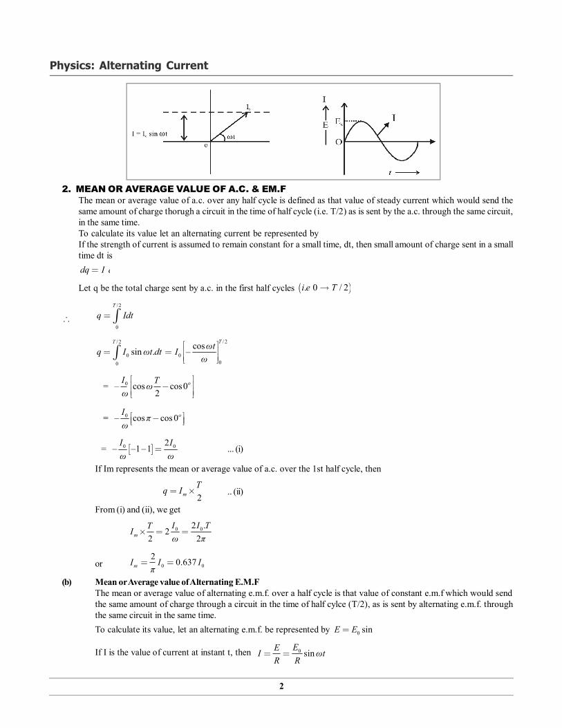
2. MEAN OR AVERAGE VALUE OF A.C. & EM.FThe mean or average value of a.c. over any half cycle is defined as that value of steady current which would send thesame amount of charge thorugh a circuit in the time of half cycle (i.e. T/2) as is sent by the a.c. through the same circuit,in the same time.To calculate its value let an alternating current be represented byIf the strength of current is assumed to remain constant for a small time, dt, then small amount of charge sent in a smalltime dt isdq I dt
Let q be the total charge sent by a.c. in the first half cycles . 0 / 2i e T
/2
0
T
q Idt
/ 2/ 2
0 000
cossin . –TT ωtq I ωt dt I
ω
= 0– cos cos02
oI Tωω
= 0– cos cos 0oI πω
= 0 02– –1 –1
I Iω ω
... (i)
If Im represents the mean or average value of a.c. over the 1st half cycle, then
2mTq I .. (ii)
From (i) and (ii), we get
0 02 .2
2 2mI I TTIω π
or 0 02 0.637mI I Iπ
(b) Mean or Average value of Alternating E.M.FThe mean or average value of alternating e.m.f. over a half cycle is that value of constant e.m.f which would sendthe same amount of charge through a circuit in the time of half cylce (T/2), as is sent by alternating e.m.f. throughthe same circuit in the same time.To calculate its value, let an alternating e.m.f. be represented by 0 sinE E ωt
If I is the value of current at instant t, then 0 sinEEI ωt
R R
3
Physics: Alternating Current
0 sin
where R is resistance of the circuit.If this current remains constant for a small time dt, then small amount of charge sent by alternating e.m.f in the smalltime dt is
Edq Idt ωt dtR
Time charge sent by alternating e.m.f in the first half cycle 0 / 2T would be
q = 0
/ 2/ 20 0
0
cossin –TT E E ωtωt dt
R R ω
= 0– cos – cos 02
oE TωωR
= 0– cos – cos 0oE πωR
q = 0 02– –1 –1
E EωR ωR
... (iii)
If Em is mean or average value of alternating e.m.f. over the first half cycle, then E TR 2
mq ... (iv)
from (iii) and (iv),
0 0 02 2 222 2
mE E E E TTπR ωR π RR
T
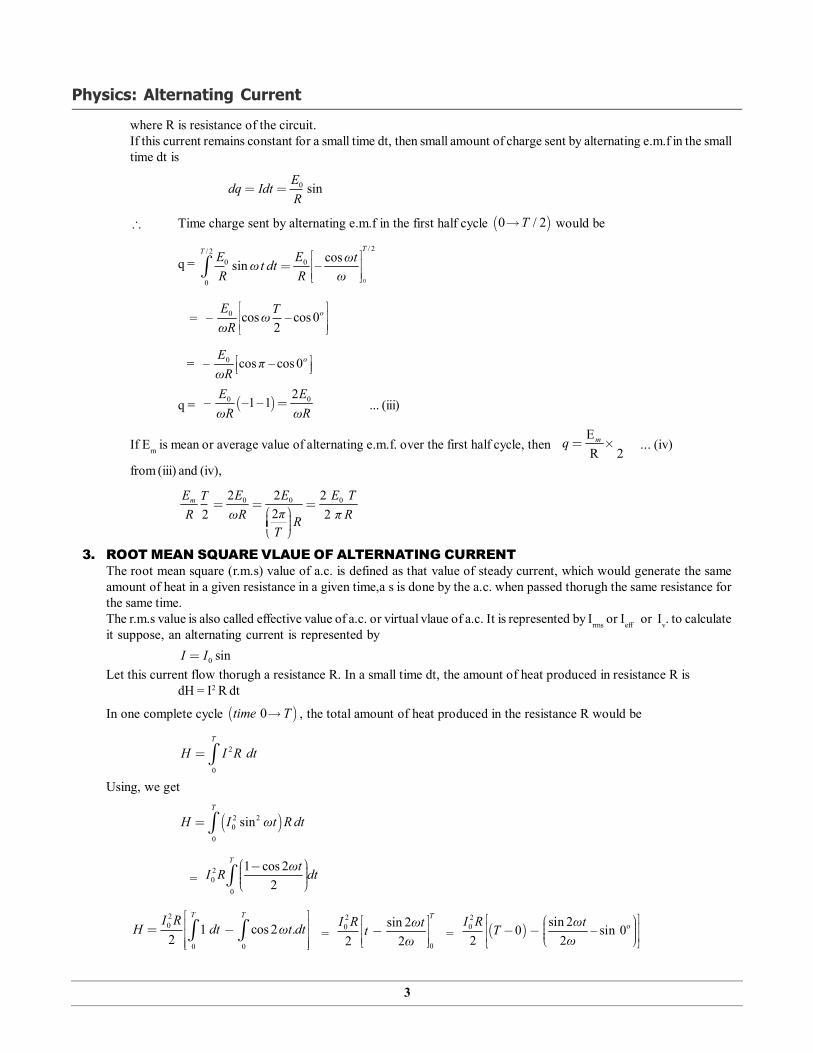
3. ROOT MEAN SQUARE VLAUE OF ALTERNATING CURRENTThe root mean square (r.m.s) value of a.c. is defined as that value of steady current, which would generate the sameamount of heat in a given resistance in a given time,a s is done by the a.c. when passed thorugh the same resistance forthe same time.The r.m.s value is also called effective value of a.c. or virtual vlaue of a.c. It is represented by Irms or Ieff or Iv. to calculateit suppose, an alternating current is represented by
0 sinI I ωtLet this current flow thorugh a resistance R. In a small time dt, the amount of heat produced in resistance R is
dH = I2 R dt
In one complete cycle 0time T , the total amount of heat produced in the resistance R would be
2
0
T
H I R dt Using, we get
2 20
0
sinT
H I ωt Rdt
= 20
0
1 cos 22
T ωtI R dt
20
0 0
1 cos 2 .2
T TI RH dt ωt dt
=
20
0
sin 22 2
TI R ωttω
= 2
o0 sin 20 – sin 02 2
I R ωtTω
4
Physics: Alternating Current
= 20 sin 2 22 2
I R πTω
20
2I RTH ... (v)
If r.m.s value or virtual vlaue of a.c. is represented by Iv , then the amount of heat produced in the same resistance R, in thesame time t would be
2vH I RT ... (vi)
From (v) and (vi), we get2
2 0
2vI RTI RT
000.707
2vI
I I
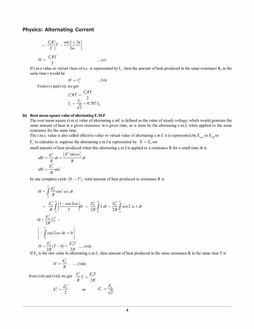
(b) Root mean square value of alternating E.M.FThe root mean square (r.m.s) value of alternating e.mf. is defined as the value of steady voltage; which would generate thesame amount of heat in a given resistance in a given time, as is done by the alternating e.m.f, when applied to the sameresistance for the same time.The r.m.s. value is also called effective value or virtual value of alternating e.m.f. it is represented by Erms or Eeff orEv to calculate it, suppose the alternating e.m.f is represented by 0 sinE E ωtsmall amount of heat produced when this alternating e.m.f is applied to a resistance R for a small time dt is
22 sinE ωtEdH dt dtR R
02
2sinE
dH ωt dtR
In one complete cycle 0 T , total amount of heat produced in resistance R is
220
0
H = sinT E ωt dt
R
= 20
0
1 cos 22
TE ωt dtR
= 2 20 0
0 0
1 cos 22 2
T TE Edt ω t dtR R
H = 0
20
2TE
t zeroR
0
cos 2 0T
ωt dt
2 20 00
2 2E E T
H TR R
......(vii)
If Ev is the rms value fo alternating e.m.f., then amount of heat produced in the same resistance R in the same time T is20E
H TR
.....(viii)
from (vii) and (viii) we get 2 2
0
2vE E TT
R R
22 0
2vE
E or 0
2vEE

5
Physics: Alternating Current
i.e. 0 00
1.4142. 0.70722 2v
E EE E
Hence r.m.s vaue of alternating e.m.f is 0.707 times the peak value of alternating e.m.f.4. ALTERNATING CURRENT THROUGH A PURE RESISTIVE CIRCUIT
An a.c resistive circuit is a circuit having only resistance component in it (i.e.a resistor R).In the a.c circuit shown an a.c source of alternating e.m.f (E) is connected toa pure resistance ‘R’The alternating emf is given by E = Eo sin t … (i)As soon as the circuit is closed, a.c. current I starts flowing such that,
EIR = E I =R
Using (i) we have,
oEI sin ωt
R
oI I sin ω t … (ii)
oI is the maximum value of current.
From o0
EI =
R, it is clear that an a.c
circuit too satisfies ohm’s law andthe behaviour of R in a.c. circuit issame as it is in d.c circuit, i.e. R canreduce a.c as well as d.c equallyeffectively.Comparing equations (i) and (ii) itis clear that E and I are in phase.Phasor diagram for a resistance circuitThe diagram shows that the current and voltage phasors are at the same phase.
5. AC THROUGH AN INDUCTORAn inductive circuit is a circuit having only inductor as a component in it.The circuit can be as shown
If Id
dt is the rate of change of current through L at any instant, then the induced emf in the inductor = – L Id
dt .
The – ve sign indicates that induced emf opposes the change of current.In order to maintain the flow of current in the circuit, applied emf must be equal and opposite of the induced voltage.
i.e., oIE – – L E sin t
dtd
oEI sin t
Ld ω dt … (1)
Integrating both sides of (1), we getoEI sin t
Ldt
o oE – E– cosI cos tL L
t I
6
Physics: Alternating Current
o– EI sin –L 2
t
o– EI sin –L 2
t
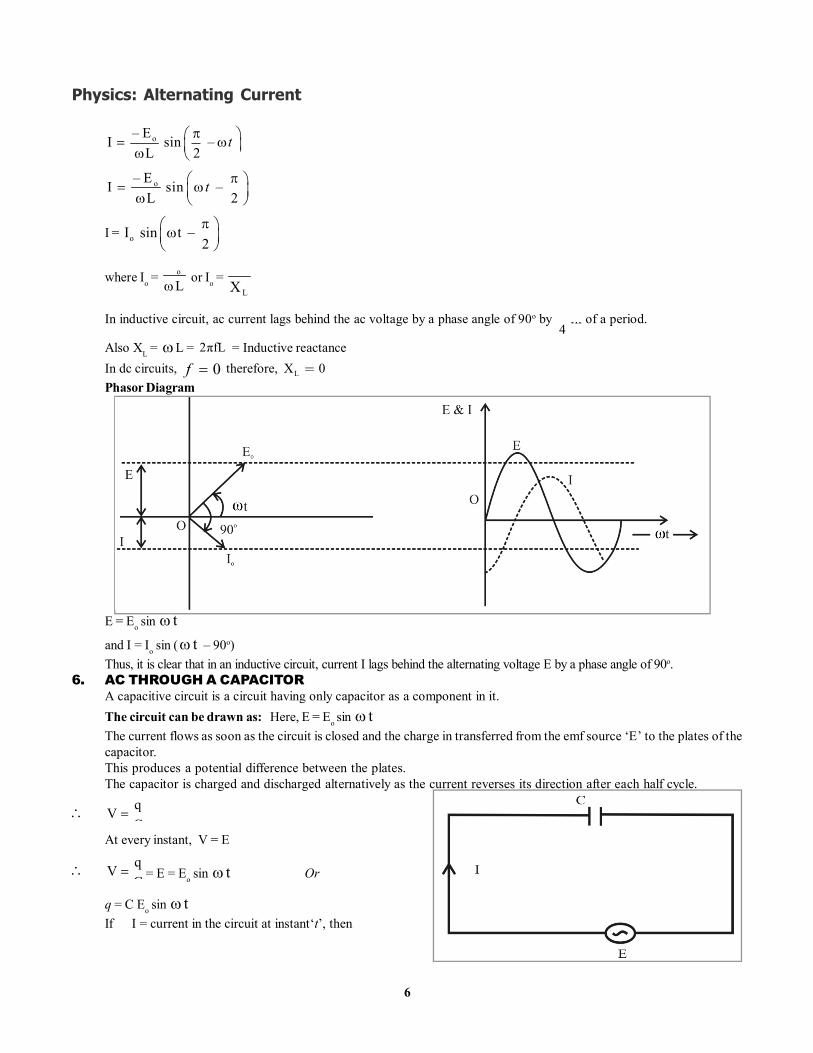
I = oI sin t –2
where Io = oEL
or Io = o
L
EX
In inductive circuit, ac current lags behind the ac voltage by a phase angle of 90o by 1 th4
of a period.
Also XL = L = 2πfL = Inductive reactanceIn dc circuits, 0f therefore, LX 0Phasor Diagram
E = Eo sin tand I = Io sin ( t – 90o)Thus, it is clear that in an inductive circuit, current I lags behind the alternating voltage E by a phase angle of 90o.
6. AC THROUGH A CAPACITORA capacitive circuit is a circuit having only capacitor as a component in it.The circuit can be drawn as: Here, E = Eo sin tThe current flows as soon as the circuit is closed and the charge in transferred from the emf source ‘E’ to the plates of thecapacitor.This produces a potential difference between the plates.The capacitor is charged and discharged alternatively as the current reverses its direction after each half cycle.
qVC
At every instant, V = E
qVC
= E = Eo sin t Or
q = C Eo sin tIf I = current in the circuit at instant‘t’, then
7
Physics: Alternating Current
I = dq ddt dt
(C Eo sin t)
I = C Eo (cos t)
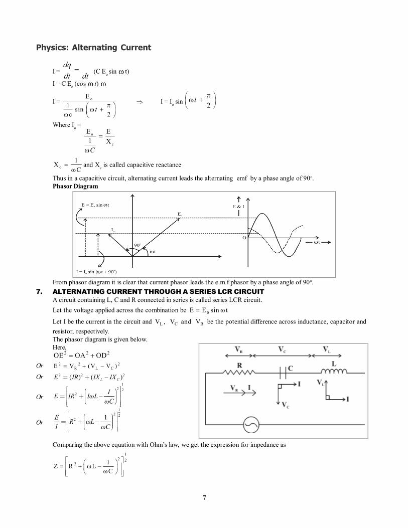
I = oE1 sinc 2
t
I = Io sin 2
t
Where Io = o o
c
E E1 X
C
c1XC
and Xc is called capacitive reactance
Thus in a capacitive circuit, alternating current leads the alternating emf by a phase angle of 90o.Phasor Diagram
From phasor diagram it is clear that current phasor leads the e.m.f phasor by a phase angle of 90o.7. ALTERNATING CURRENT THROUGH A SERIES LCR CIRCUIT
A circuit containing L, C and R connected in series is called series LCR circuit.Let the voltage applied across the combination be 0E E sin t
Let I be the current in the circuit and L C RV , V and V be the potential difference across inductance, capacitor andresistor, respectively.The phasor diagram is given below.Here,
2 2 2OE OA OD Or 2 2 2
R L CE V (V – V )
Or 2 2 2( ) ( – )L CE IR IX IX
Or
12 2
2 – IE IR IωLωC
Or
12 2
2 1–E R ωLI ωC
Comparing the above equation with Ohm’s law, we get the expression for impedance as1
2 22 1Z R L –
C
Physics/Class XII 8 © 2012 Vidyamandir Classes Pvt. Ltd.
Physics: Alternating Current
Hand-Out Chapter - 7
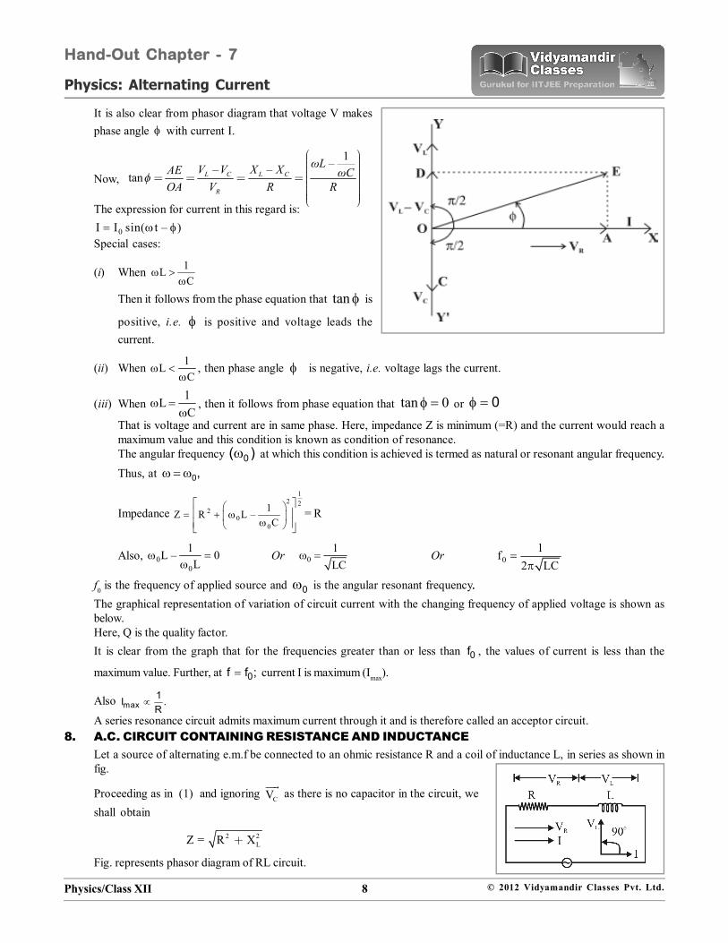
It is also clear from phasor diagram that voltage V makesphase angle with current I.
Now,
1–– –tan L C L C
R
ωLV V X XAE ωCOA V R R
The expression for current in this regard is:
0I I sin( t – ) Special cases:
(i) When 1LC
Then it follows from the phase equation that tan is
positive, i.e. is positive and voltage leads thecurrent.
(ii) When 1LC
, then phase angle is negative, i.e. voltage lags the current.
(iii) When 1LC
, then it follows from phase equation that tan 0 or 0That is voltage and current are in same phase. Here, impedance Z is minimum (=R) and the current would reach amaximum value and this condition is known as condition of resonance.The angular frequency 0( ) at which this condition is achieved is termed as natural or resonant angular frequency..Thus, at 0,
Impedance
12 2
20
0
1Z R L –C
= R
Also, 00
1L – 0L
Or 01LC
Or 01f
2 LC
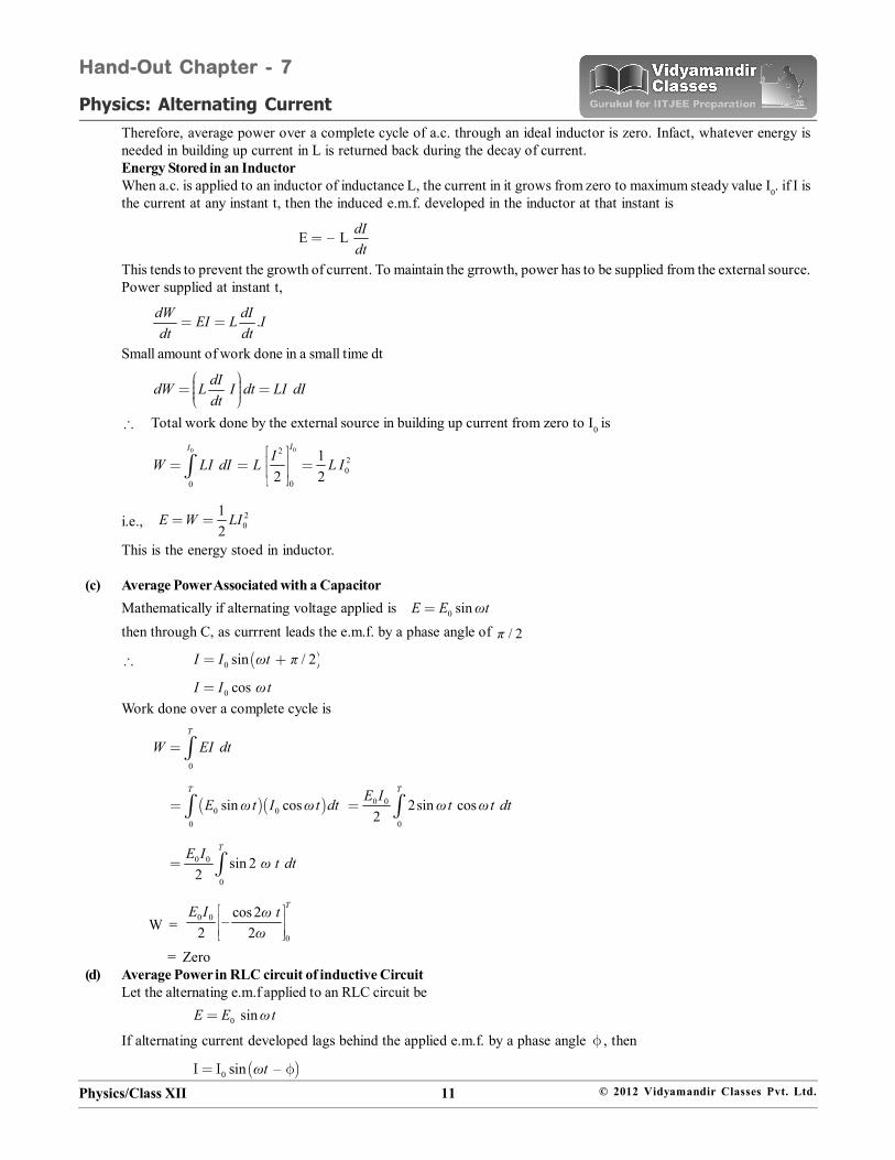
f0 is the frequency of applied source and 0 is the angular resonant frequency..The graphical representation of variation of circuit current with the changing frequency of applied voltage is shown asbelow.Here, Q is the quality factor.It is clear from the graph that for the frequencies greater than or less than 0f , the values of current is less than the
maximum value. Further, at 0f f ; current I is maximum (Imax).
Also max1I .R
A series resonance circuit admits maximum current through it and is therefore called an acceptor circuit.8. A.C. CIRCUIT CONTAINING RESISTANCE AND INDUCTANCE
Let a source of alternating e.m.f be connected to an ohmic resistance R and a coil of inductance L, in series as shown infig.
Proceeding as in (1) and ignoring CV
as there is no capacitor in the circuit, weshall obtain
2 2LZ = R X
Fig. represents phasor diagram of RL circuit.
Physics/Class XII 9 © 2012 Vidyamandir Classes Pvt. Ltd.
Physics: Alternating Current
Hand-Out Chapter - 7
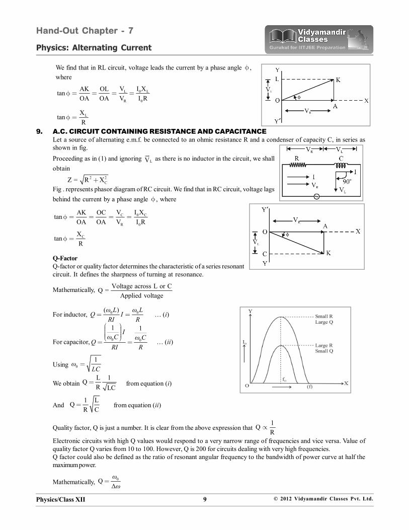
We find that in RL circuit, voltage leads the current by a phase angle ,where
0 LL
R 0
I XVAK OLtanOA OA V I R
LXtan
R
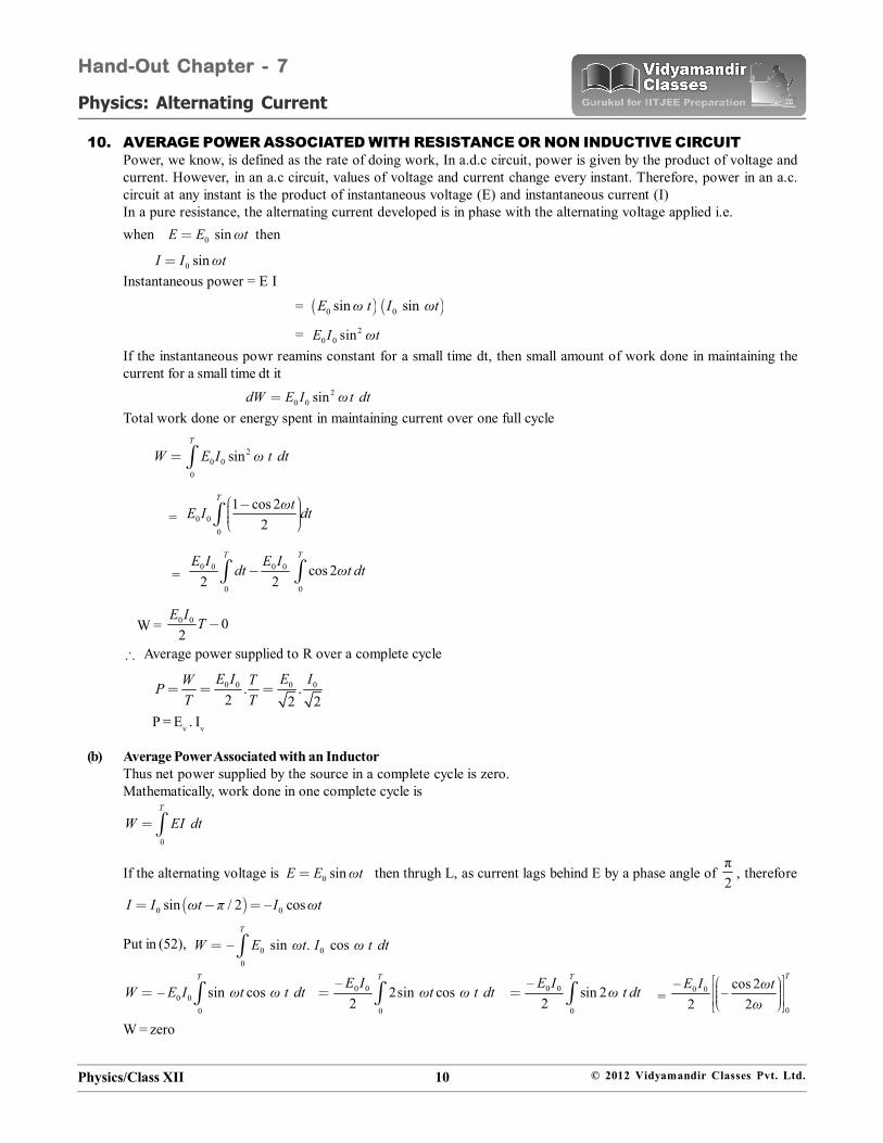
9. A.C. CIRCUIT CONTAINING RESISTANCE AND CAPACITANCELet a source of alternating e.m.f. be connected to an ohmic resistance R and a condenser of capacity C, in series asshown in fig.Proceeding as in (1) and ignoring LV
as there is no inductor in the circuit, we shall
obtain2 2
CZ = R XFig . represents phasor diagram of RC circuit. We find that in RC circuit, voltage lagsbehind the current by a phase angle , where
C 0 C
R 0
V I XAK OCtanOA OA V I R
CXtan
R
Q-FactorQ-factor or quality factor determines the characteristic of a series resonantcircuit. It defines the sharpness of turning at resonance.
Mathematically, Voltage across L or CQ =Applied voltage
For inductor, 0 0( )ω L ω LQ IRI R
… (i)
For capacitor, 0 0
1 1Iω C ω C
QRI R
… (ii)
Using 01ω
LC
We obtain L 1QR LC
from equation (i)
And 1 LQR C
from equation (ii)
Quality factor, Q is just a number. It is clear from the above expression that 1QR
Electronic circuits with high Q values would respond to a very narrow range of frequencies and vice versa. Value ofquality factor Q varies from 10 to 100. However, Q is 200 for circuits dealing with very high frequencies.Q factor could also be defined as the ratio of resonant angular frequency to the bandwidth of power curve at half themaximum power.
Mathematically, 0QΔωω
Physics/Class XII 10 © 2012 Vidyamandir Classes Pvt. Ltd.
Physics: Alternating Current
Hand-Out Chapter - 7
10. AVERAGE POWER ASSOCIATED WITH RESISTANCE OR NON INDUCTIVE CIRCUITPower, we know, is defined as the rate of doing work, In a.d.c circuit, power is given by the product of voltage andcurrent. However, in an a.c circuit, values of voltage and current change every instant. Therefore, power in an a.c.circuit at any instant is the product of instantaneous voltage (E) and instantaneous current (I)In a pure resistance, the alternating current developed is in phase with the alternating voltage applied i.e.when 0 sinE E ωt then
0 sinI I ωtInstantaneous power = E I
= 0 0sin sinE ω t I ωt
= 20 0 sinE I ωt
If the instantaneous powr reamins constant for a small time dt, then small amount of work done in maintaining thecurrent for a small time dt it
20 0 sindW E I ωt dt
Total work done or energy spent in maintaining current over one full cycle
20 0
0
sinT
W E I ω t dt
= 0 00
1 cos 22
T ωtE I dt
= 0 0 0 0
0 0
cos 22 2
T TE I E Idt ωt dt
W = 0 0 02
E I T
Average power supplied to R over a complete cycle
0 0 0 0. .2 2 2
E I E IW TPT T
P = Ev . Iv
(b) Average Power Associated with an InductorThus net power supplied by the source in a complete cycle is zero.Mathematically, work done in one complete cycle is
0
T
W EI dt
If the alternating voltage is 0 sinE E ωt then thrugh L, as current lags behind E by a phase angle of π2
, therefore
0 0sin / 2 – cosI I ωt π I ωt
Put in (52), 0 00
– sin . cosT
W E ωt I ω t dt
0 00
– sin cosT
W E I ωt ω t dt 0 0
0
–2sin cos
2
TE I ωt ω t dt 0 0
0
–sin 2
2
TE I ω t dt = 0 0
0
– cos 2–2 2
TE I ωtω
W = zero
Physics/Class XII 11 © 2012 Vidyamandir Classes Pvt. Ltd.
Physics: Alternating Current
Hand-Out Chapter - 7
Therefore, average power over a complete cycle of a.c. through an ideal inductor is zero. Infact, whatever energy isneeded in building up current in L is returned back during the decay of current.Energy Stored in an InductorWhen a.c. is applied to an inductor of inductance L, the current in it grows from zero to maximum steady value I0. if I isthe current at any instant t, then the induced e.m.f. developed in the inductor at that instant is
E – L dIdt
This tends to prevent the growth of current. To maintain the grrowth, power has to be supplied from the external source.Power supplied at instant t,
.dW dIEI L Idt dt
Small amount of work done in a small time dt
dIdW L I dt LI dIdt
Total work done by the external source in building up current from zero to I0 is
00 220
00
12 2
IIIW LI dI L L I
i.e., 20
12
E W LI
This is the energy stoed in inductor.
(c) Average Power Associated with a CapacitorMathematically if alternating voltage applied is 0 sinE E ωt
then through C, as currrent leads the e.m.f. by a phase angle of / 2π
0 sin / 2I I ωt π
0 cosI I ωtWork done over a complete cycle is
0
T
W EI dt
0 00
sin cosT
E ωt I ωt dt 0 0
0
2sin cos2
TE I ωt ωt dt
0 0
0
sin 22
TE I ω t dt
W = 0 0
0
cos 2–2 2
TE I ω tω
= Zero(d) Average Power in RLC circuit of inductive Circuit
Let the alternating e.m.f applied to an RLC circuit be
0 sinE E ωt
If alternating current developed lags behind the applied e.m.f. by a phase angle , then
0 sin –ωt
Physics/Class XII 12 © 2012 Vidyamandir Classes Pvt. Ltd.
Physics: Alternating Current
Hand-Out Chapter - 7
Power at instant t,
dW E Idt
0 0sin sindW E ωt I ωtdt
= 0 0 sin sin cos – cos sinE I ωt ωt ω t
= 20 0 0 0sin cos – sin cos sinE I ωt E I ωt ω t
= 2 0 00 0 sin cos – sin 2 sin
2E IE I ωt ωt
If this instantaneous power is assumed to remain constant for a small time dt, then small amount of work done in thistime is
2 0 00 0 sin cos – sin 2 sin
2E IdW E I ω t ω t θ dt
total work done over a complete cycle is
2 0 00 0
0 0
sin cos – sin 2 sin2
T T E IW E I ω t dt ωt dt
2 0 00 0
0 0
cos sin – sin sin 22
T TE IW E I ω t dt ωt dt
As 2
0 0
sin and sin 2 02
T TTω t dt ωt dt
0 0 cos2TW E I
0 0 0 0cos. cos
T 2 2 2E I E IW TP
T
cosv vP E I
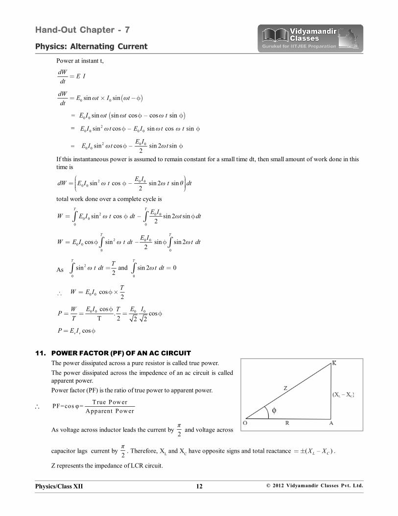
11. POWER FACTOR (PF) OF AN AC CIRCUITThe power dissipated across a pure resistor is called true power.The power dissipated across the impedence of an ac circuit is calledapparent power.Power factor (PF) is the ratio of true power to apparent power.
True Pow erPF=cos φ=Apparent Power
As voltage across inductor leads the current by 2π
and voltage across
capacitor lags current by 2π
. Therefore, XL and XC have opposite signs and total reactance ( – )L CX X .
Z represents the impedance of LCR circuit.
Physics/Class XII 13 © 2012 Vidyamandir Classes Pvt. Ltd.
Physics: Alternating Current
Hand-Out Chapter - 7
PF 2 2L C
R
R (X – X )
So, PF, R ResistancecosZ Impedance
In a non- inductive circuit,
L CX X
Therefore, 2
Rcos 1 90R
This is the maximum value of power factor.In a pure inductor or a capacitor
90 , i.e. PF = 0
Therefore, average power consumed in such circuits isos90rms rmsP V I c = 0
Current through pure inductor L or capacitor C consumes no power for its maintenance in the circuit and that is whythis is called the idle current or wattless current.For LCR circuit it can be shown that the average power consumed by the circuit
av rms rmsP E I cos
At resonance (as cos = 0),
0 0av rms rms
E IP E I2 2
Or, av 0 01P E I2
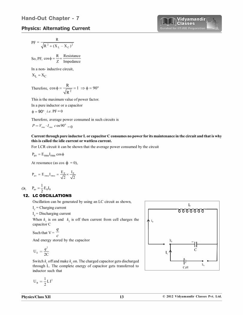
12. LC OSCILLATIONSOscillation can be generated by using an LC circuit as shown,IC = Charging currentId = Discharging currentWhen k1 is on and k2 is off then current from cell charges thecapacitor C
Such that V = qc
And energy stored by the capacitor
2
EU2Cq
Switch k1 off and make k2 on. The charged capacitor gets dischargedthrough L. The complete energy of capacitor gets transferred toinductor such that
2B
1U L I2
Physics/Class XII 14 © 2012 Vidyamandir Classes Pvt. Ltd.
Physics: Alternating Current
Hand-Out Chapter - 7
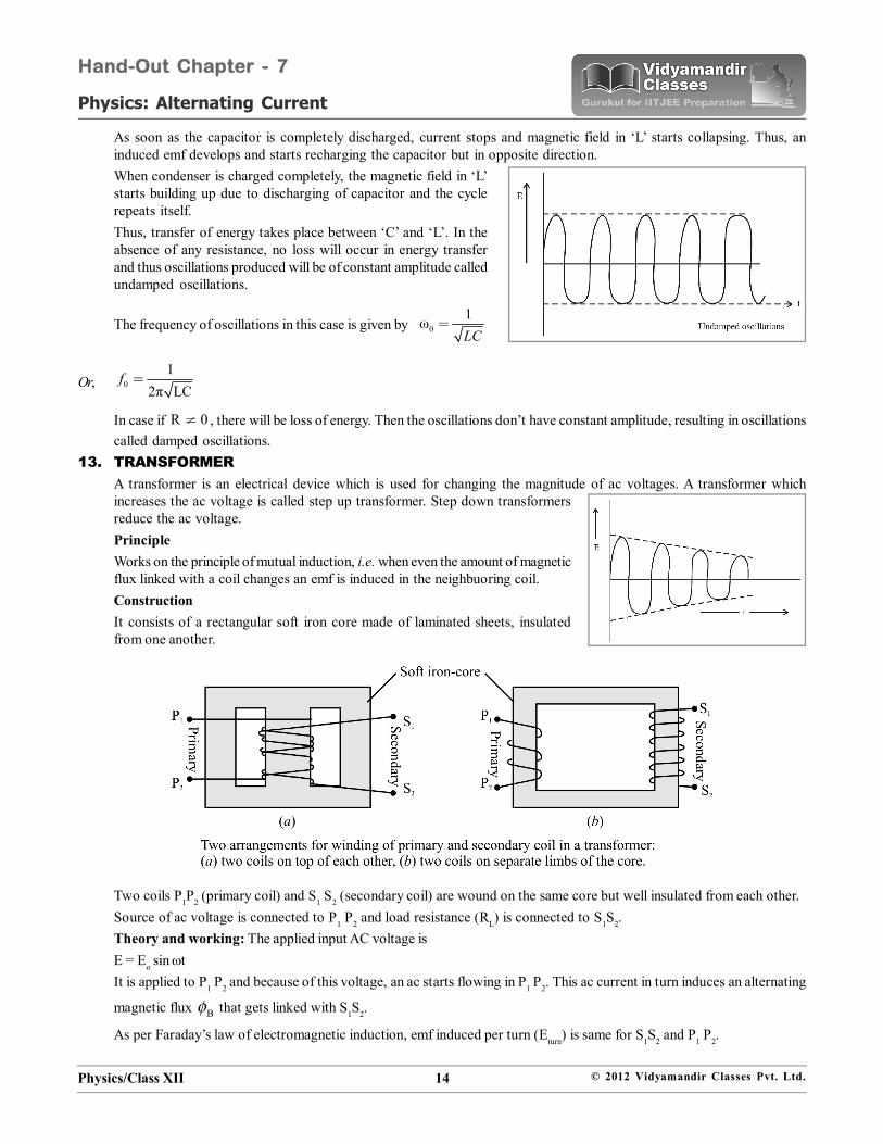
As soon as the capacitor is completely discharged, current stops and magnetic field in ‘L’ starts collapsing. Thus, aninduced emf develops and starts recharging the capacitor but in opposite direction.When condenser is charged completely, the magnetic field in ‘L’starts building up due to discharging of capacitor and the cyclerepeats itself.Thus, transfer of energy takes place between ‘C’ and ‘L’. In theabsence of any resistance, no loss will occur in energy transferand thus oscillations produced will be of constant amplitude calledundamped oscillations.
The frequency of oscillations in this case is given by 01ωLC
Or, 01
2π LCf
In case if R 0 , there will be loss of energy. Then the oscillations don’t have constant amplitude, resulting in oscillationscalled damped oscillations.
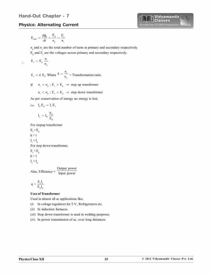
13. TRANSFORMERA transformer is an electrical device which is used for changing the magnitude of ac voltages. A transformer whichincreases the ac voltage is called step up transformer. Step down transformersreduce the ac voltage.PrincipleWorks on the principle of mutual induction, i.e. when even the amount of magneticflux linked with a coil changes an emf is induced in the neighbuoring coil.ConstructionIt consists of a rectangular soft iron core made of laminated sheets, insulatedfrom one another.
Two coils P1P2 (primary coil) and S1 S2 (secondary coil) are wound on the same core but well insulated from each other.Source of ac voltage is connected to P1 P2 and load resistance (RL) is connected to S1S2.Theory and working: The applied input AC voltage isE = Eo sin tIt is applied to P1 P2 and because of this voltage, an ac starts flowing in P1 P2. This ac current in turn induces an alternating
magnetic flux B that gets linked with S1S2.
As per Faraday’s law of electromagnetic induction, emf induced per turn (Eturn) is same for S1S2 and P1 P2.
Physics/Class XII 15 © 2012 Vidyamandir Classes Pvt. Ltd.
Physics: Alternating Current
Hand-Out Chapter - 7
p sBturn
E EE
p s
ddt n n
np and ns are the total number of turns in primary and secondary respectively.Ep and Es are the voltages across primary and secondary respectively.
s pE E s
p
nn
s PE Ek Where s
p
nkn
= Transformation ratio.
If s p; E E step up transformers pn n
s p; E E step down transformers pn n
As per conservation of energy no energy is lost,
i.e. p p s sI E I E
Ps P
S
EI I
E
For stepup transformerEs > Ep
k > 1Is < Ip
For step down transformer,Es < Ep
k < 1Is > Ip
Also, Efficiency = Output powerInput power
s s
p p
E Iq =
E I
Uses of TransformerUsed in almost all ac applications like,(i) In voltage regulators for T.V., Refrigerators etc.(ii) In induction furnaces.(iii) Step down transformer is used in welding purposes.(iv) In power transmission of ac. over long distances.

Physics/Class XII 16 © 2012 Vidyamandir Classes Pvt. Ltd.
Physics: Alternating Current
Hand-Out Chapter - 7
20121. The figure shows a series LCR circuit with L = 10.0 H, C = 40 F, R = 60 connected to a variable frequency 240 V source,
calculate (i) the angular frequency of the source which drives the circuit at resonance, (ii) the current at the resonatingfrequency, (iii) the rms potential drop across the inductor at resonance. (3 marks)
L
R
C2011
20111. Define the term ‘wattless current’. (1 marks)2. (i) With the help of a labelled diagram, describe briefly
the underlying principle and working of a step uptransformer.(ii) Write any two sources of energy loss in atransformer.(iii) A step up transformer converts a low input voltageinto a high output voltage. Does it violate law ofconservation of energy? Explain. (5 marks)
3. Derive an expression for the impedance of a series LCR circuit connected to an AC supply of variable frequency.Plot a graph showing variation of current with the frequency of the applied voltage. Explain briefly how the phenomenonof resonance in the circuit can be used in the tuning mechanism of a radio or a TV set. (5 marks)
20101. A coil Q is connected to low voltage bulb B and placed near another coil P as shown in the figure. Give reasons to
explain the following observations: (2 Marks)(a) The bulb ‘B’ lights(b) Bulb gets dimmer if the coil Q is moved towards left.
2. Describe briefly, with the help of a labelled diagram, the basic elements of an A.C. generator. State its underlyingprinciple. Show diagrammatically how an alternating emf is generated by a loop of wire rotating in a magnetic field. Writethe expression for the instantaneous value of the emf induced in the rotating loop.
(5 Marks)3. A series LCR circuit is connected to a source having voltage v = vm sin t. Derive the expression for the instantaneous
current I and its phase relationship to the applied voltage.Obtain the condition for resonance to occur. Define ‘Power factor’. State the conditions under which it is (i) maximumand (ii) minimum. (5 Marks)
20091. (a) Derive an expression for the average power consumed in a series LCR circuit connected to a.c. source in which the
phase difference between the voltage and the current i the circuit is .(b) Define the quality factor in an a.c. circuit. Why should the quality factor have high value in receiving circuits.
Name the factors on which it depends. (5 Marks)
Physics/Class XII 17 © 2012 Vidyamandir Classes Pvt. Ltd.
Physics: Alternating Current
Hand-Out Chapter - 7
2. (a) Derive the relationship between the peak and the rms value of current in an a.c. circuit.(b) Describe briefly, with the help of a labelled diagram, working of a step-up transformer.
A step-up transformer converts a low voltage into high voltage. Does it not violate the principle of conservationof energy. Explain (5 Marks)
20081. An inductor 200mH, capacitor 500 F, resistor 10 are connected in series with a 100 V, variable frequency ac source.
Calculate the(i) frequency at which the power factor of the circuit is unity(ii) current amplitude at this frequency(iii) Q-factor (3 Marks)
20071. In a series LCR circuit, the voltages across an inductor, a capacitor and a resistor are 30 V, 30 V and 60 V respectively.
What is the phase difference between the applied voltage and the current in the circuit. (1 Mark)2. Distinguish between the terms ‘average value’ and ‘rms value’ of an alternating current. The instantaneous current from
an ac source is I = 5 sin (314 t) ampere. What are the average and rms values of the current. (2 Marks)3. Calculate the current drawn by the primary coil of a transformer which steps down 200 V to 20 V to operate a device of
resistance. Assume the efficiency of the transformer to be 80%. (2 Marks)4. An ac voltage of 100 V, 50 Hz is connected across a 20 ohm resistor and mH inductor in series. Calculate (i) impedance
of the circuit, (ii) rms current in the circuit. (2 Marks)5. Explain with the help of a labelled diagram the underlying principle and working of a step-up transformer. Why cannot
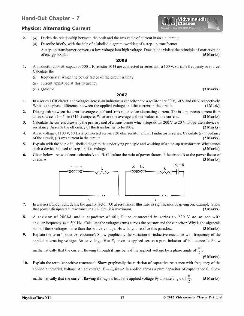
such a device be used to step-up d.c. voltage. (3 Marks)6. Given below are two electric circuits A and B. Calculate the ratio of power factor of the circuit B to the power factor of
circuit A. (3 Marks)
7. In a series LCR circuit, define the quality factor (Q) at resonance. Illustrate its significance by giving one example. Showthat power dissipated at resonance in LCR circuit is maximum. (3 Marks)
8. A resistor of 200 and a capacitor of 40 F are connected in series to 220 V ac source withangular frequency ω = 300 Hz . Calculate the voltages (rms) across the resistor and the capacitor. Why is the algebraicsum of these voltages more than the source voltage. How do you resolve this paradox. (3 Marks)
9. Explain the term ‘inductive reactance’. Show graphically the variation of inductive reactance with frequency of theapplied alternating voltage. An ac voltage 0 sinE E ωt is applied across a pure inductor of inductance L. Show
mathematically that the current flowing through it lags behind the applied voltage by a phase angle of 2π
.
(5 Marks)10. Explain the term ‘capacitive reactance’. Show graphically the variation of capacitive reactance with frequency of the
applied alternating voltage. An ac voltage 0 sinE E ωt is applied across a pure capacitor of capacitance C. Show
mathematically that the current flowing through it leads the applied voltage by a phase angle of 2π
. (5 Marks)
Physics/Class XII 18 © 2012 Vidyamandir Classes Pvt. Ltd.
Physics: Alternating Current
Hand-Out Chapter - 7
20061. A capacitor and a resistor are connected in series with an ac source. If the potential difference across C, R are 120 V, 90
V rspectively and if the r.m.s. current of the circuit is 3 A, calculate the (i) impedance, (ii) power factor of the circuit.(2 Marks)
2. An inductor 200 mH, a capacitor C and a resistor 10 ohm are connected in series with a 100 V, 50 s–1 ac source. If thecurrent and voltage are in phase with each other, calculate the capacitance of the capacitor. (2 Marks)
3. When an inductor L and a resistor R in series are connected across a 12 V, 50Hz supply, a current of 0.5 A flows in the
circuit. The current differs in phase from applied voltage by 3π
radians. Calculate the value of R. (3 Marks)
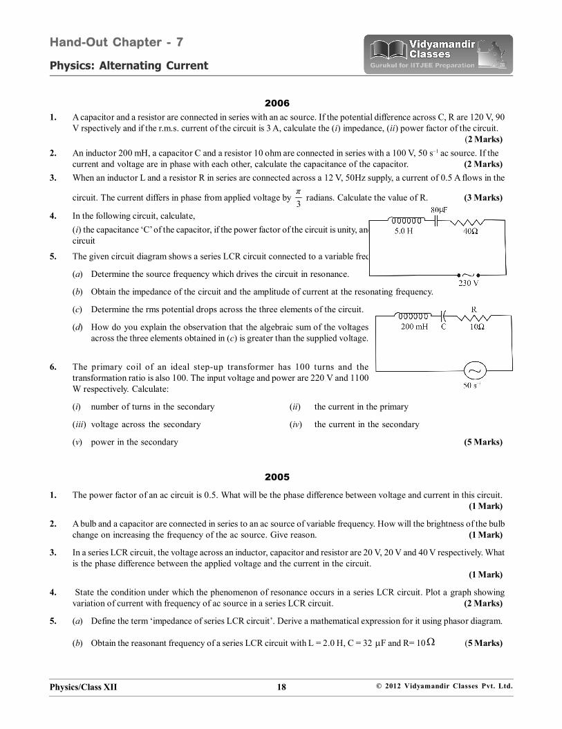
4. In the following circuit, calculate,(i) the capacitance ‘C’ of the capacitor, if the power factor of the circuit is unity, and (ii) also calculate the Q-factor of thecircuit
5. The given circuit diagram shows a series LCR circuit connected to a variable frequency 230 V source: (5 Marks)
(a) Determine the source frequency which drives the circuit in resonance.
(b) Obtain the impedance of the circuit and the amplitude of current at the resonating frequency.
(c) Determine the rms potential drops across the three elements of the circuit.
(d) How do you explain the observation that the algebraic sum of the voltagesacross the three elements obtained in (c) is greater than the supplied voltage.
6. The primary coil of an ideal step-up transformer has 100 turns and thetransformation ratio is also 100. The input voltage and power are 220 V and 1100W respectively. Calculate:
(i) number of turns in the secondary (ii) the current in the primary
(iii) voltage across the secondary (iv) the current in the secondary
(v) power in the secondary (5 Marks)
2005
1. The power factor of an ac circuit is 0.5. What will be the phase difference between voltage and current in this circuit.(1 Mark)
2. A bulb and a capacitor are connected in series to an ac source of variable frequency. How will the brightness of the bulbchange on increasing the frequency of the ac source. Give reason. (1 Mark)
3. In a series LCR circuit, the voltage across an inductor, capacitor and resistor are 20 V, 20 V and 40 V respectively. Whatis the phase difference between the applied voltage and the current in the circuit.
(1 Mark)
4. State the condition under which the phenomenon of resonance occurs in a series LCR circuit. Plot a graph showingvariation of current with frequency of ac source in a series LCR circuit. (2 Marks)
5. (a) Define the term ‘impedance of series LCR circuit’. Derive a mathematical expression for it using phasor diagram.
(b) Obtain the reasonant frequency of a series LCR circuit with L = 2.0 H, C = 32 F and R= 10 (5 Marks)