ALSM Data Collection Overview Preliminary imagery from GeoEarthScope Northern California LiDAR...
24
ALSM Data Collection Overview Preliminary imagery from GeoEarthScope Northern California LiDAR project. Final data products will be freely available from www.earthscope.org in coming months.
-
Upload
elise-scales -
Category
Documents
-
view
213 -
download
0
Transcript of ALSM Data Collection Overview Preliminary imagery from GeoEarthScope Northern California LiDAR...

ALSM Data Collection Overview
Preliminary imagery from GeoEarthScope Northern California LiDAR project.
Final data products will be freely available from www.earthscope.org in coming months.

Acknowledgements
• NCALM• Ken Hudnut (USGS)• Mike Bevis (OSU)

EarthScope
• Funded by NSF and conducted in partnership with the USGS and NASA
• EarthScope Facility– Seismic observatory (USArray)
– The San Andreas Fault Observatory at Depth (SAFOD) – Plate Boundary Observatory (PBO)
“EarthScope is a bold undertaking to apply modern observational, analytical and telecommunications technologies to investigate the structure and evolution of the North American continent and the physical processes controlling earthquakes and volcanic eruptions.”

• Includes acquisition of aerial and satellite
imagery and geochronology.
• Part of the EarthScope Facility project
funded by NSF (MREFC).
• Managed at UNAVCO.
• Assist with EarthScope instrument siting.
• Examine strain field at different
temporal/spatial scales than geodetic &
seismic instrumentation.
• Data will be freely available.
GeoEarthScope

UNAVCO
• UNAVCO is a membership-governed
consortium that supports and
promotes Earth science by advancing
high-precision techniques for the
measurement and understanding of
deformation
• UNAVCO is funded by NSF and NASA
• UNAVCO Facility supports PI projects
• UNAVCO is constructing the
EarthScope PBO
• UNAVCO manages GeoEarthScope
• UNAVCO hosts WInSAR
• UNAVCO is based in Boulder, CO, with
five regional offices to construct PBO

LiDAR and UNAVCO
• UNAVCO manages Airborne LiDAR (ALSM) acquisition projects for GeoEarthScope
• UNAVCO Facility provides GPS equipment and engineering support for Airborne LiDAR (ALSM) projects
• UNAVCO Facility acquiring pool of Tripod LiDAR (TLS) scanning instruments to support community projects

Airborne Laser Swath Mapping (ALSM)
Data Collection
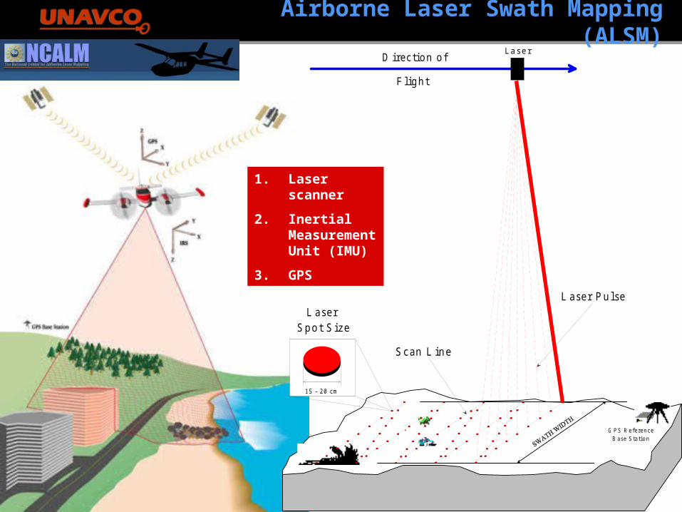
Airborne Laser Swath Mapping (ALSM)
1 5 - 2 0 c m
D irec tio n o f
F lig h t
G P S R e fe re n c eB a se S ta tio n
Laser
L ase r P u lseL ase r
S p o t S ize
S can L in e
1. Laser scanner
2. Inertial Measurement Unit (IMU)
3. GPS

Surface Point Spacing
Variable(1 - 30 m )
Spot 1
Spot 2
Spot 3
Spot 4
Spot 5
Spot 9
Spot 17
Spot 25
Spot 12
User definable to provide necessary point pacing on the surface

ALSM and InSAR
Comparisons of Techniques for measuring surfaces and detecting changes in surfaces*
GPS InSAR ALSM TLS
Sample
Density
1 site/10 km2 10,000 pixels/ km2 1-10 hits/ m2 1000 hits/ m2
Position
Precision
1-20 mm 2-3 m 5-15 cm 0.6-5 cm
Change
Detection
1 mm 1-2 cm 10 cm 1 cm
Scale Global 100 km 10-100 Km 1 km
* Ball park numbers for typical applications

• Aircraft: Cessna 337 Skymaster• Personnel
• One pilot, one operator in plane• GPS ground crew (2 to 10+ people)
• Scanner: Optech near-IR• PRF: 33-125 KHz• Flying height: 600 – 1,000m AGL• Flying speed: 120 mph• Swath overlap: 50% nominal• Ground truthing: GPS (campaign & CORS)• Navigation solution: KARS• Point spacing: sub-meter• Nominal Accuracy (on open hard and flat surface)
• Vertical: 3 – 6 cm.• Horizontal: 20 – 30 cm.
ALSM Data Collection Parameters (NCALM)

Some ALSM Acquisition Issues
• Target identification and prioritization
• Defining collection scheme and data product requirements
– Tradeoffs concerning resolution vs. coverage
– GPS ground control requirements
– End use: geomorphology, geodesy, etc.
– Cost (B4 ~$500/sq.km., NoCal ~$400/sq.km., DV ~$300/sq.km.)
– Will the data be useful to users 5+ years from now?
• Seasonal constraints
– “Leaf off”, snow, heat, etc.
• Data volume…lots of TB’s…yikes!
• Standard data products?
• Distribution scheme?

Workflow
• Project planning
– Target I.D., LiDAR parameters, GPS parameters, flight lines,
permits, etc.
• Data collection
– Flying and GPS deployments
• GPS data processing and trajectory generation
– Kinematic software (KARS, TRACK, etc.)
• LiDAR range processing and XYZ point cloud generation
– Proprietary software (at present)
– Filtered and unfiltered (e.g. full return and bare earth models)
• Surface generation
– Software (Surfer, Arc, GLW, etc.)
– Algorithms (tinning, kriging, etc.)
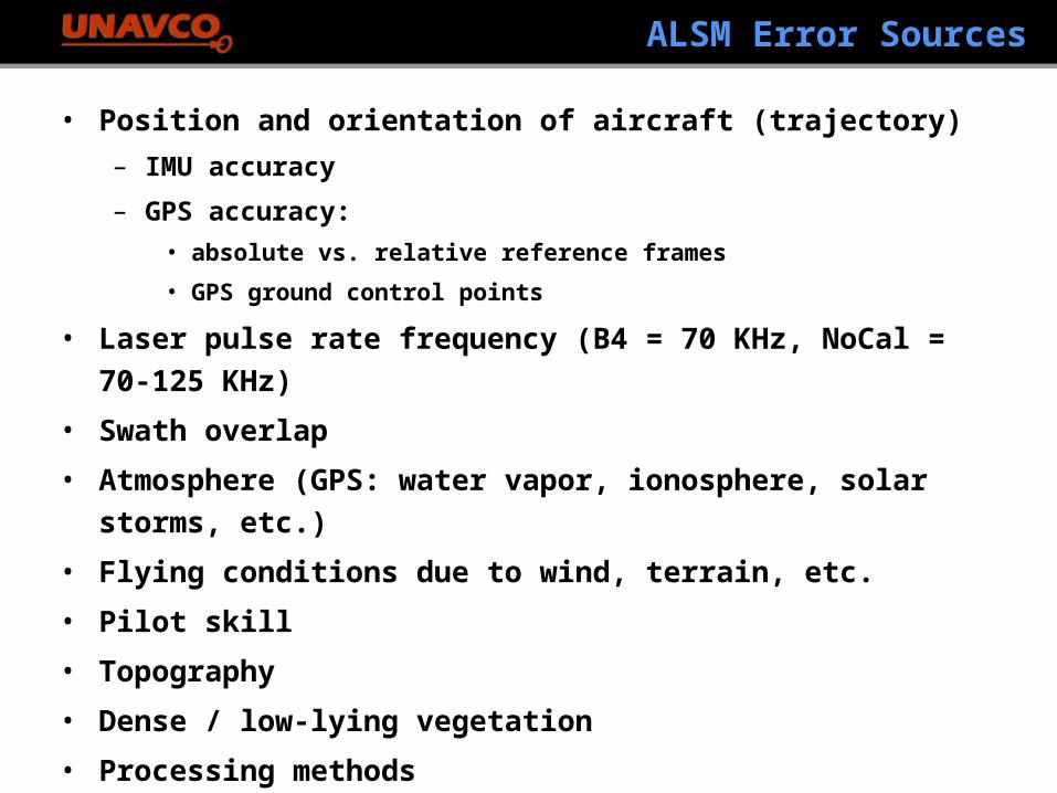
ALSM Error Sources
• Position and orientation of aircraft (trajectory)
– IMU accuracy
– GPS accuracy:
• absolute vs. relative reference frames
• GPS ground control points
• Laser pulse rate frequency (B4 = 70 KHz, NoCal = 70-125 KHz)
• Swath overlap
• Atmosphere (GPS: water vapor, ionosphere, solar storms, etc.)
• Flying conditions due to wind, terrain, etc.
• Pilot skill
• Topography
• Dense / low-lying vegetation
• Processing methods
• Many more, many yet to be identified…new field

SURFER 0.5 m DEM from NCALM - standard product
scanedge
Corduroy
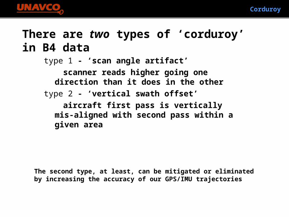
Corduroy
There are two types of ‘corduroy’ in B4 data
type 1 - ‘scan angle artifact’
scanner reads higher going one direction than it does in the other
type 2 - ‘vertical swath offset’
aircraft first pass is vertically mis-aligned with second pass within a given area
The second type, at least, can be mitigated or eliminated by increasing the accuracy of our GPS/IMU trajectories

Scan artifact - at scan edge on dry lake one sees a patternof up-down consistently; as mirror flips, height reads differently
Corduroy - type 1

Corduroy - type 2
scanedge
The inner scan is consistently lower than the outer scan;this is a different source of ‘corduroy,’ the second type.
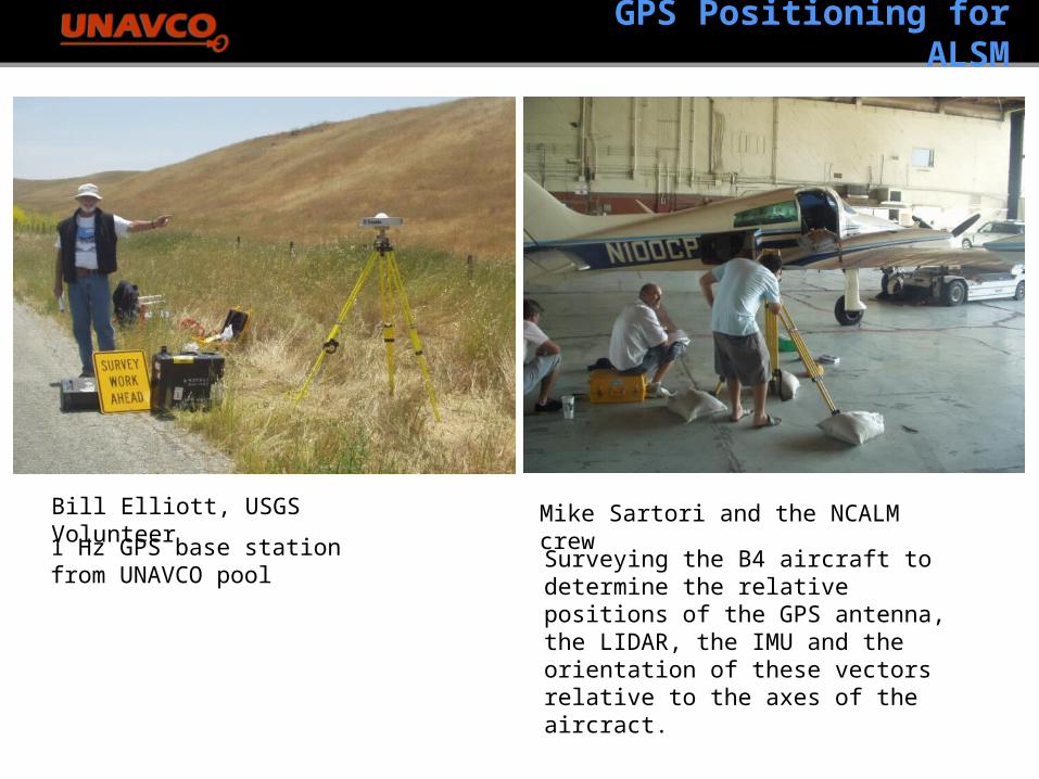
GPS Positioning for ALSM
Bill Elliott, USGS Volunteer
1 Hz GPS base station from UNAVCO pool
Mike Sartori and the NCALM crew
Surveying the B4 aircraft to determine the relative positions of the GPS antenna, the LIDAR, the IMU and the orientation of these vectors relative to the axes of the aircract.


B4 Project: Swath and GPS Points


• Southern/eastern California
• Intermountain Seismic Belt
• Pacific Northwest
• Alaska
Future GeoES LiDAR Projects