Alphatronic Propulsion Control Systems
26
MAN B&W Diesel A/S, Alpha, Denmark Contents: Alphatronic 2000 PCS Propulsion Control System Introduction ............................................................................................................ 3 Ship’s Propulsion Power – controlled by Alphatronic ......................................... 3 – Evolution of control .............................................................................................. 3 – Accumulated expertise ......................................................................................... 3 – Control is crucial .................................................................................................. 3 – Inherent advantages ............................................................................................ 4 – The engine and propeller manufacturer’s advantage ............................................. 4 Alphatronic Propulsion Control System – General .............................................. 4 – Plant configurations ............................................................................................. 4 – Included in the system ......................................................................................... 5 – Engine equipment ................................................................................................ 5 – Primary control function ....................................................................................... 5 – In case of emergency ........................................................................................... 6 – Load control ........................................................................................................ 6 – Control lever orders and commands .................................................................... 6 – Load program ...................................................................................................... 7 – Charge air limit curves ......................................................................................... 7 Modes of operation ................................................................................................ 8 – Combined mode .................................................................................................. 8 – Constant speed mode ......................................................................................... 8 – Separate mode .................................................................................................... 8 Bridge main manoeuvre panels ............................................................................. 9 – Bridge wing manoeuvre panels ............................................................................ 9 – Control levers in the manoeuvring handle panels .................................................. 9 – Electrical shaft system ......................................................................................... 10 – Telegraph system integrated in manoeuvre panels ................................................ 10 – Propulsion Control Panel ..................................................................................... 11 Interfaces to external systems .............................................................................. 12 – Voyage Data Recorder ......................................................................................... 12 – Power Take Home (PTH) ...................................................................................... 12 – Power Boost. ....................................................................................................... 12 – Power Take Off .................................................................................................... 12 – Gear and clutches ................................................................................................ 14 – Safety system ...................................................................................................... 15 – Engine ................................................................................................................. 16 – Joystick / coordinated control system .................................................................. 19 Main Cabinet ........................................................................................................... 20 Installation .............................................................................................................. 20 Cable plans ............................................................................................................. 24 – Commissioning .................................................................................................... 25 Instruction Manual ................................................................................................. 25
-
Upload
harshad-khire -
Category
Documents
-
view
760 -
download
22
Transcript of Alphatronic Propulsion Control Systems

MAN B&W Diesel A/S, Alpha, Denmark
Contents:
Alphatronic 2000 PCSPropulsion Control System
Introduction ............................................................................................................ 3
Ship’s Propulsion Power – controlled by Alphatronic ......................................... 3
– Evolution of control .............................................................................................. 3
– Accumulated expertise ......................................................................................... 3
– Control is crucial .................................................................................................. 3
– Inherent advantages ............................................................................................ 4
– The engine and propeller manufacturer’s advantage ............................................. 4
Alphatronic Propulsion Control System – General .............................................. 4
– Plant configurations ............................................................................................. 4
– Included in the system ......................................................................................... 5
– Engine equipment ................................................................................................ 5
– Primary control function ....................................................................................... 5
– In case of emergency ........................................................................................... 6
– Load control ........................................................................................................ 6
– Control lever orders and commands .................................................................... 6
– Load program...................................................................................................... 7
– Charge air limit curves ......................................................................................... 7
Modes of operation ................................................................................................ 8
– Combined mode .................................................................................................. 8
– Constant speed mode ......................................................................................... 8
– Separate mode .................................................................................................... 8
Bridge main manoeuvre panels ............................................................................. 9
– Bridge wing manoeuvre panels ............................................................................ 9
– Control levers in the manoeuvring handle panels .................................................. 9
– Electrical shaft system ......................................................................................... 10
– Telegraph system integrated in manoeuvre panels ................................................ 10
– Propulsion Control Panel ..................................................................................... 11
Interfaces to external systems .............................................................................. 12
– Voyage Data Recorder ......................................................................................... 12
– Power Take Home (PTH) ...................................................................................... 12
– Power Boost. ....................................................................................................... 12
– Power Take Off .................................................................................................... 12
– Gear and clutches ................................................................................................ 14
– Safety system ...................................................................................................... 15
– Engine ................................................................................................................. 16
– Joystick / coordinated control system .................................................................. 19
Main Cabinet ........................................................................................................... 20
Installation .............................................................................................................. 20
Cable plans ............................................................................................................. 24
– Commissioning .................................................................................................... 25
Instruction Manual ................................................................................................. 25


3
Alphatronic 2000 PCSPropulsion Control System
IntroductionThe purpose of the Product Informa-tion brochure is to act as a guidelineduring project planning and lay out ofthe Alphatronic Propulsion ControlSystems. The brochure gives adescription of the system in general,standard control elements and optionsavailable for tailoring a remote controlsystem for the individual vessel and itspropulsion system configuration, oper-ating modes and manoeuvre stations.Our product range is constantly underreview, being developed and improvedaccording to present and future re-quirements and conditions. We there-fore reserve the right to make changesto the technical specificationsand data without prior notice.Alphatronic Propulsion ControlSystems are usually specified togetherwith MAN B&W Alpha ControllablePitch Propellers.The propeller programme may bestudied in separate literature.
Ship’s Propulsion Power –controlled by AlphatronicMAN B&W Diesel A/S, Alpha launchedthe first CP propeller as part of a pro-pulsion system in 1902. A completepackage including engine, clutch,
shafting and propeller. A packagewhere all control and manoeuvre ac-tions were carried out, in accordancewith the standards of that time, locallyby hands–on.
Evolution of controlIn view of the following years of devel-opment, not only in the physicaldimensions of the ships, but also inthe propulsion equipment itself, – thecontrol and manoeuvre actions shiftedfrom local to remote by means of dif-ferent intermediates. These intermedi-ates developed from mechanical push/pull rod systems, flexible cable sys-tems, pneumatic systems up tilltoday’s electronic systems. Year byyear, both the operator and the equip-ment itself required more and moresophisticated control systems foreconomical cruising at various operat-ing modes, engine load sharing, re-dundant propulsion using PTI etc.The latest version of the Alphatronicsystem described in this material istype Alphatronic 2000 PCS. PCS is anabbreviation of Propulsion Control Sys-tem.
Accumulated expertiseSince 1902, more than 6500 propellersand propulsion packages have gone
into service – operated by varioustypes of MAN B&W Alpha control sys-tems. Today’s standard for MAN B&WAlpha CP propellers and propulsionpackages is the well–proven electronicremote control system, Alphatronic.Since its introduction in 1982, morethan 930 systems have been deliveredfor a wide range of propulsion plantcombinations with two–stroke enginesand propellers, four–stroke engines,reduction gearboxes and propellers forthe output range up to 30,000 kW(40,800 bhp) per propeller.
Control is crucialIn the process of projecting and esti-mating propulsion systems, the associ-ated control system is a ‘soft’ item fre-quently handled with less attention.The propulsion control system is oftenregarded as a necessary auxiliaryelement that just follows the primarypropulsion elements. But the fuel andpropulsion efficiency of the ‘hard’ engineand propeller elements are, however,undermined – without the correctmatching and performing controlsystem!
Fig. 1: Two–stoke propulsion package (8S50MC-C engine, tunnel gear, VBS1680 propeller)
4
Inherent advantagesA tailored Alphatronic control systemensures:• Safe control of the propulsion plant
and reliable manoeuvring of the ship• Economic operation due to
optimised engine/propeller loadcontrol
• Quick system response and efficientCP propeller manoeuvrability
• Load changes controlled in such away that the governor always keepsthe engine speed within the rangerequired, and thus prevents black-out during shaft alternator operation
• Good long term engine performancedue to overload protection
• Thermal protection of the engine viacontrolled running–up programmes
• Environmental friendliness due tobalanced manoeuvring dynamicsduring acceleration with minimalsmoke emission
• Flexibility and individualcustomization due to modularsystem principles
• Project support, simple installationprocedures and safe commissioning
• Minimal service and maintenancerequirements
• User–friendly operator functions dueto logic and ergonomic design ofcontrol panels
• Overall system reliability and durabil-ity
• Type approval by all major Classifica-tion Societies
The engine and propeller manufacturer’sadvantageIn general, the control system acts asthe central propulsion package ele-ment, being in charge of the remainingpropulsion package elements, their co-herence and their interaction with oneanother.The knowledge inherent in theAlphatronic systems, accumulatedduring 21 years of service:• Full knowledge of all propulsion
package elements• Full knowledge of two–stroke and
four–stroke engine design• Full knowledge of CP propeller de-
sign• Full knowledge regarding overall op-
erating economy, long term perfor-mance, load characteristics and sys-tem dynamics
– makes all the difference.
Alphatronic PropulsionControl System – GeneralWith this electronic propulsion controlsystem it is possible for the navigatorto manoeuvre the ship from the bridge.The navigator may operate the controlsystem without consideration for theengine load condition, since the sys-tem ensures automatic engine over-load protection.When desired, the manoeuvre respon-sibility may be transferred from themain bridge panel to the bridge wingpanels or to the control room panel.
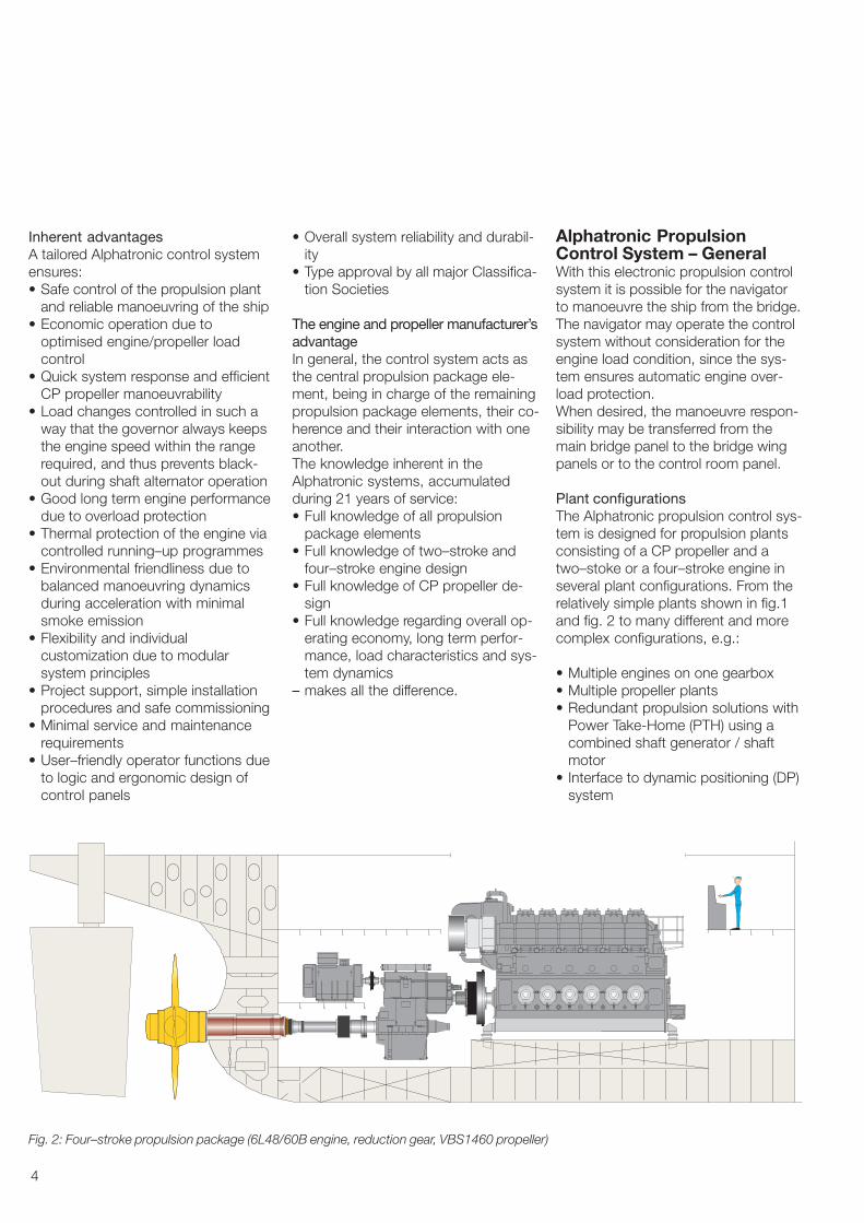
Plant configurationsThe Alphatronic propulsion control sys-tem is designed for propulsion plantsconsisting of a CP propeller and atwo–stoke or a four–stroke engine inseveral plant configurations. From therelatively simple plants shown in fig.1and fig. 2 to many different and morecomplex configurations, e.g.:
• Multiple engines on one gearbox• Multiple propeller plants• Redundant propulsion solutions with
Power Take-Home (PTH) using acombined shaft generator / shaftmotor
• Interface to dynamic positioning (DP)system
Fig. 2: Four–stroke propulsion package (6L48/60B engine, reduction gear, VBS1460 propeller)

5
Included in the systemA typical system consists of the follow-ing main components shown in theprinciple diagram fig. 3 :1 Manoeuvre panels for main bridge
(centre and wings)2 Manoeuvre panel for engine control
room3 Main cabinet including the process
computer4 Propeller servo electronics (closed
loop amplifier and propeller indica-tion electronics)
Engine equipmentThe governor and the safety systemare considered part of the engine andtherefore not a part of the propulsioncontrol system. Nevertheless, there isa close connection between these. Fordetails of interfacing engine, governorand safety system, please refer to theinterface descriptions on page 12.
Primary control functionThe manoeuvre panels are fitted withmanoeuvre levers for controlling thepropeller speed and pitch. The lever onthe bridge centre panel and the leveron the ECR panel have individual po-tentiometers connected to the maincabinet.Depending on the chosen mode of op-eration, these lever signals will be usedfor setting the engine speed and thepropeller pitch accordingly.
An electric speed setting signal istransmitted from the PCS main cabinetto the engine governor. If the enginehas a governor with pneumatic speedsetting, the electric speed order is con-verted into a pressure using an E/P–converter.
The propeller pitch is controlled by twosolenoid valves in the hydraulic sys-tem. The electronic servo unit controlsthe solenoid valves for ’ahead’ and’astern’ pitch changes by comparingactual pitch and set point. Actual pro-peller pitch is measured by two trans-mitters. One transmitter is used for
Fig. 3: Control system structure
1. Bridge wing 1. Main Bridge
2. Engine control room
3. Main cabinet
1. Bridge wing
4. Propellerservo electronics

6
indication of the actual position of thepropeller. The other transmitter givesthe feedback signal to the electronicservo unit.
In case of emergencyIf the propulsion control system is outof service, the propulsion plant maystill be operated from the bridge usingthe back-up system. The back-up sys-tem is independent of the main controlsystem, although it is operated fromthe same lever on the bridge.Selection of back-up will set the gover-nor to a fixed speed (normally corre-sponding to the nominal shaft genera-tor speed) and set the propeller pitchcorresponding to the present thrust.Change between normal control andback-up control will thus not changethe actual propeller thrust.
Load controlThe control system uses the propellerpitch and engine speed as controllingparameters. Fuel pump index, enginespeed and charge air pressure areused as feedback. The engine load iskept within the limits as specified bythe load limit curve of the engine. Theload curve for combined mode is ad-justed according to the specific engineand propulsion equipment – taking fueloil consumption, propeller efficiencyand manoeuvrability into considerationin order to obtain optimum overall pro-pulsion efficiency.
Control lever orders and commandsIn order to allow the engine and thevessel to respond, the system is ableto control the rate at which the enginespeed and the propeller pitch ischanged. The control lever orders aretranslated into engine speed and pro-peller pitch commands as shown in fig5. The slew rates will vary with theplant configurations.In addition to these slew rates, pitchwill be dynamically limited by the loadprogram and the actual charge airpressure.
Fig. 4: General load diagram
Fig. 5: Control lever slew rate for propeller pitch command
�100�80�60�40�20
020406080
100
�20 0 20 40 60
time [sec.]
Normal pitch rate ahead Pitch rate at crash stopNormal engine speed rate Engine speed rate at crash stopNormal pitch rate astern
Pitch and engine speed slew rates
Propeller pitch [%]
60 65 70 75 80 85 90 95 100
Speed [%]
Load Diagram
0
10
20
30
40
50
60
70
80
90
100
2
1
45
3
6
Theoretical Propeller Curve1 Combinator Curve4
100% MEP2 50% MEP5
Load Limit3 Zero Thrust Curve6
Power [%]
7
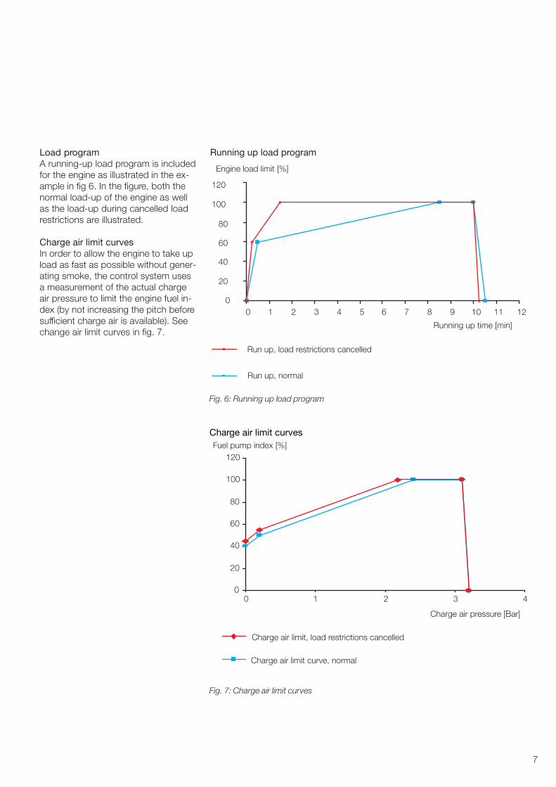
Load programA running-up load program is includedfor the engine as illustrated in the ex-ample in fig 6. In the figure, both thenormal load-up of the engine as wellas the load-up during cancelled loadrestrictions are illustrated.
Charge air limit curvesIn order to allow the engine to take upload as fast as possible without gener-ating smoke, the control system usesa measurement of the actual chargeair pressure to limit the engine fuel in-dex (by not increasing the pitch beforesufficient charge air is available). Seechange air limit curves in fig. 7.
Fig. 6: Running up load program
Running up load program
0
20
40
60
80
100
120
0 1 2 3 4 5 6 7 8 9 10 11 12
Running up time [min]
Engine load limit [%]
Run up, normal
Run up, load restrictions cancelled
Fig. 7: Charge air limit curves
0 1 2 3 4
Charge air pressure [Bar]
Charge air limit, load restrictions cancelled
Charge air limit curve, normal
0
20
40
60
80
100
120Fuel pump index [%]
Charge air limit curves
8
Modes of operationThe propulsion plant can be operated inthree different modes.
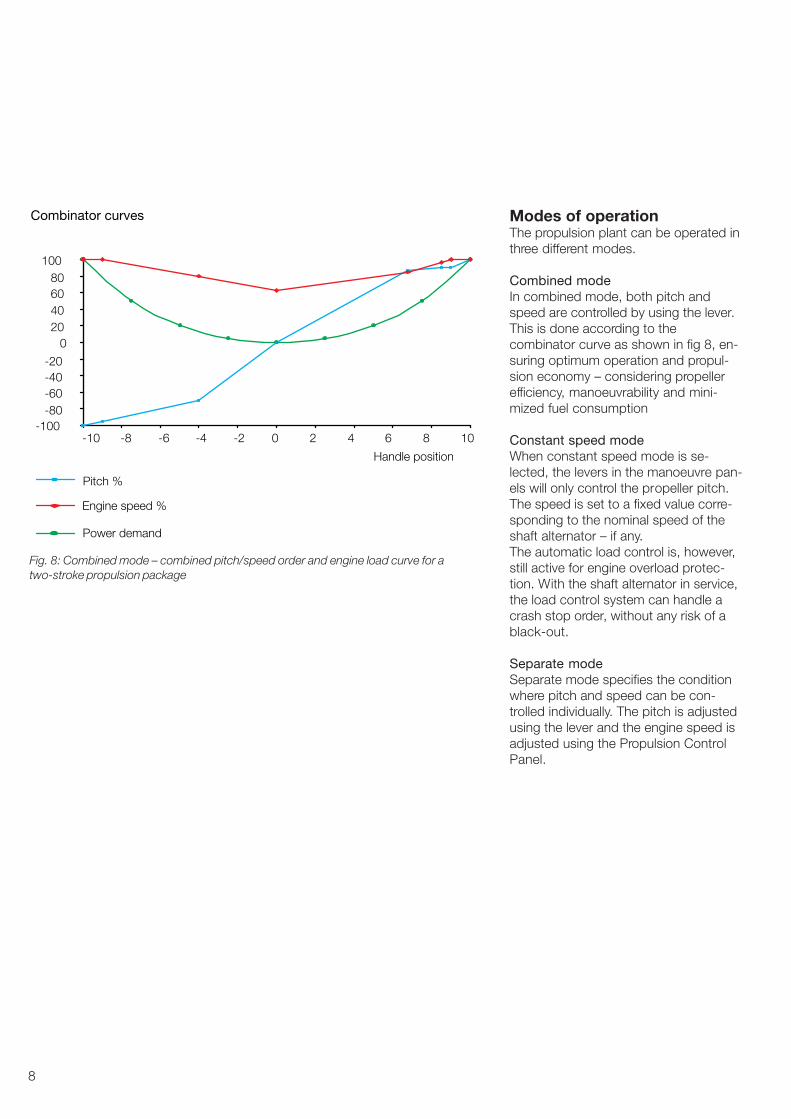
Combined modeIn combined mode, both pitch andspeed are controlled by using the lever.This is done according to thecombinator curve as shown in fig 8, en-suring optimum operation and propul-sion economy – considering propellerefficiency, manoeuvrability and mini-mized fuel consumption
Constant speed modeWhen constant speed mode is se-lected, the levers in the manoeuvre pan-els will only control the propeller pitch.The speed is set to a fixed value corre-sponding to the nominal speed of theshaft alternator – if any.The automatic load control is, however,still active for engine overload protec-tion. With the shaft alternator in service,the load control system can handle acrash stop order, without any risk of ablack-out.
Separate modeSeparate mode specifies the conditionwhere pitch and speed can be con-trolled individually. The pitch is adjustedusing the lever and the engine speed isadjusted using the Propulsion ControlPanel.
Fig. 8: Combined mode – combined pitch/speed order and engine load curve for atwo-stroke propulsion package
�100�80�60�40�20
020406080
100
Combinator curves
Handle position
�10 �8 �6 �4 �2 0 2 4 6 8 10
Power demand
Pitch %
Engine speed %

9
Bridge main manoeuvrepanelsAs a minimum the propulsion controlsystem will always include a mainbridge panel per engine/propeller,please refer to fig. 9.The main manoeuvre panel consists ofthree individual panels:• Propeller Instrument Panel, PIP
Indicating propeller speed and pro-peller pitch. These two instrumentsare working independently of the re-mote control system. The light dim-mer is operating on both PIP andMHP.
• Manoeuvring Handle Panel, MHPIncorporates the control lever andnormally also an emergency stoppush-button, a push-button for se-lection of back-up control and push-button /indicator for selection of con-trol position.
• Propulsion Control Panel, PCPThe primary functions of the panelare selection of control position andoperating mode. In addition, certainsafety functions and special machin-ery operation, including alarm lists,are available.
All three panels have the standard in-strument sizes 144 mm x 288 mm forconvenient installation together withother standard instruments in thebridge and ECR consoles.
Bridge wing manoeuvre panelsTypically, two bridge wing panels aresupplied. Wing panels are available inindoor and outdoor versions. Indoorwing panels may optionally beequipped with a Propulsion ControlPanel if desired. Please refer to figures10 and 11.
Control levers in the manoeuvringhandle panelsFig. 12 shows a typical control leverconfiguration. The control lever in thebridge main manoeuvre panel is con-nected to the main cabinet of the re-mote control system.
Fig. 9: Bridge manoeuvre panel – main bridge
Fig. 10: Bridge manoeuvre panel – bridge wing indoor
Fig. 11: Bridge manoeuvre panel – bridge wing outdoor

10
As standard the engine control room(ECR) is equipped with a similar controllever. Optionally the system can be de-livered without equipment in the en-gine control room.The control lever in the bridge mainmanoeuvre panel and the control leverin the ECR are independent of eachother.
Electrical shaft systemShips with bridge wing control areequipped with an electrical shaft sys-tem interconnecting the bridge mainand bridge wing control levers.The electric shaft system is a so-calledsynchronizing system, in which thenon-active control levers are followingthe active control lever. I.e. when thebridge main manoeuvre panel is se-lected as “IN CONTROL”, the twobridge wing levers will automaticallyfollow the bridge main control lever.This system design secures that thehandle chosen to be “IN CONTROL”will act as a master and the otherhandles on the bridge will follow its po-sition. This will avoid any synchronizingof handles at the time of changingcontrol position on the bridge.
The electrical shaft standard solutioncan handle three panels on the bridge.However additional manoeuvring pan-els may be added, providing for typi-cally also an aft bridge. A maximum of16 panels can be controlled in oneelectrical shaft system.
Telegraph system integrated inmanoeuvre panelsOptionally, the levers at the mainbridge and in the ECR may beequipped with a telegraph dial and oneadditional pointer. The additionalpointer on the bridge always showsthe position of the corresponding tele-graph lever, being either the lever in theECR or in the engine room dependingon the actual control position. Whenan active lever is moved, normally thebridge lever, the telegraph bells will
EMERGENCY
STOP
STAND
BY
FINISH
WITH
ENGINE
TAKE
CONTROL
IN
CONTROL
BACK UP
CONTROL
ON/OFF
DEADSLOW
SLOW
HALF
FULL
STOP
DEADSLOW
SLOW
HALF
FULL
EMERGENCY
STOP
STAND
BY
FINISH
WITH
ENGINE
ON
SERVICE
TELE-
GRAPH
ON/OFF
DEADSLOW
SLOW
HALF
FULL
STOP
DEADSLOW
SLOW
HALF
FULL
Fig. 13: Main bridge and ECR manoeuvring panels withintegrated telegraph function
Bridge Wing
Setpoint, ECRSet
poin
t, B
ridge
Pitc
h S
etpo
int,
Bac
k�up
Con
trol
Main Cabinet
Main Control StationBridge Center Bridge Wing
Remote ControlSystem
Propeller PitchClosed LoopControl Box
Electric ShaftControl Box
Pitch Setpoint, RCS
Fig. 12: A configuration of manoeuvre handles

11
Propulsion Control PanelFig. 14 shows the Propulsion ControlPanel. The contents of the display willvary during operation. In basic mode,the display will indicate the availablepower, the power demand from theactive control position and the actualpower delivered by the engine. Thelast line will show the oldestunacknowledged alarm, if any.
The keys and indicators of the panelhave the following functions:
a. Control position selection and indi-cation
b. Operating mode selection and indi-cation
c. Shut down indication and operation(cancel and reset)
d. Load reduction indication andoperation (cancel and reset)
e. Indication of active load restrictions.May be cancelled by pushing key
f. Machinery control. E.g. start andstop of engine, clutching in andout. Operation via softkeys S1through S4
Propulsion Control System Alphatronic 2000
S1 S2 S3 S4
ESC ENT
MAINTE-NANCE
SHUTDOWN
LOADREDUC.
CANCELSHUTDOWN
CANCELLOAD
REDUC.
MACHI-NERY
CONTROL
RESETSHUTDOWN
RESETLOAD.REDUC
STOPHORN
ACCEPT
SEPA-RATE
CONST.SPEED
COMBI-NATOR
ENGINECONTROL
ROOM
BRIDGE LOCALCONTROL
LOADRESTRICTCANCEL
OVERLOAD
FAULTALARM
i
c e f gd
h
j
a
b
l
k
m n
Fig. 16: Propulsion Control Panel
sound until the reply pointer has thesame position as acknowledgement bythe machinery crew that the requestedorder has been understood. Please re-fer to fig. 13 showing the main bridgeand ECR manoeuvring panels with in-tegrated telegraph function.
The telegraph function is a means ofcommunication between the bridgeand the engine area. It is normally onlyused in case of problems with the re-mote control system, and thus it iselectrically independent of the remotecontrol system.
In addition to the function of communi-cating manoeuvring orders betweenbridge and engine area, the telegraphsystem will normally also have the twoadditional communication functions forFinished With Engine (FWE) and StandBy included. Activating the push but-ton FWE on the bridge will start thetelegraph bells until the correspondingpush button is acknowledged in themachinery area. The same principleapplies for the Stand By function.
g. Navigation keys for moving aroundin lists and changing parameters
h. Collective dimming of keys, indica-tors and display in panel
i. Softkeys for operation. Actual func-tion will be explained in the displayabove the key
j. Keys for stopping the horn and ac-knowledge of alarms
k. Maintenance key. Gives access toalarm lists and advanced featuresand adjustments
l. Alarm lamp. Flashing when newalarms arrive
m. Lamp for indication of engine over-load. Used during back-up controlwhere no load control is in function
n. Lamp for indication of internal faultsin the propulsion control panel itself
Generally, operation of the plant willonly be possible from the active controllocation, i.e. bridge or engine controlroom. However, display facilities are al-ways open at all panels.

12
Power Management System /Main Switch Board
Remote Control Systemtype AT2000 PCS
El�motor load4 � 20 mAGalvanically separated
ET4816
EC4817, PTI start commandClosed contact = start(2 sec. pulse)
EC4818, PTI runningClosed contact = running above95% of nominal speed
EC4819, PTI stop commandClosed contact = stop(2 sec. pulse)
PTI rpm pick�up� Number of pulsesper revolution: 4 � 999
� Type: PNP or NPNnfSE2745
Gear
Fig. 15: Interface for a PTH solution
Interfaces to externalsystemsThe Alphatronic remote control systemcan be interfaced with a variety of ex-ternal systems. Included in this docu-ment, there is a description of a num-ber of often used interfaces that haveproven to work. For each of the belowdescribed interfaces, there is a morecomprehensive description available.
Voyage Data RecorderThe Alphatronic propulsion control sys-tem is equipped with a standard inter-face for a voyage data recorder (VDR)following the standard IEC 61996 asrequired by the IMO. The electrical in-terface is done according to IEC61162-1.
Power Take Home (PTH)For a number of vessels, e.g. chemicaltankers, it is desired to have a possibil-ity of alternative propulsion power if themain engine is not available. Such al-ternative propulsion can be estab-lished by using the shaft alternator as ashaft motor. A number of prerequisitesmust be considered. It must be pos-sible to disengage the main engine be-fore the shaft motor can be engaged,and there must be a way of bringingthe shaft motor from stand still tonominal speed.
As a rule of thumb, there must be elec-trical power available corresponding toat least 25 - 30 % of the main enginepower. Preferably, the combined PTO/PTI could be connected via a twospeed gear. This will reduce the size ofthe required PTI and the associatedequipment for starting the PTI fromstand still.Fig. 15 shows the interface for a PTHsolution.
Power BoostThis feature may be relevant for shortterm boosting of the propulsion power.It is necessary that the gear and thepropeller are designed for the total
power of diesel engine and shaft mo-tor. It is necessary that the amount ofpower supplied by the shaft motor iscontrolled by the ships power manage-ment system. No electrical interface isthus necessary to the remote controlsystem.
Power Take OffThe most common type of power takeoff (PTO) is a shaft generator running ata fixed frequency. However other typesof shaft generators exist, which areable to work at variable engine speed.

13
Remote Control Systemtype AT2000 PCS
MSB / SG (PTO)
EC4811, PTO readyClosed contact = Engine runningin Constant Speed mode and withinthe nominal rpm range.
EC4813PTO out of service requestClosed contact = request start ofDiesel generator to take over load.Always required for two�stroke engines.
ET4810Shaft Generator breaker closedClosed contact = breaker closed
ECS4824PTO in service requestClosed contact (pulse) = requestWill select Constant Speed modein PCS
ECS4825PTO out of service requestClosed contact (pulse) = requestWill select Constant Speed modein PCS
Optional signals. Only required if selectionof constant speed has to be done fromthe Power Management System
ECS4812A Increase RPMClosed contact (pulse) = increase
Optional signals. Only required if SGfrequency and load control has to be donefrom the Power Management System
ECS4812B Decrease RPMClosed contact (pulse) = decrease
Optional signal.Always required for two�stroke engines.
Fig 16: Interface for a PTO solution
14
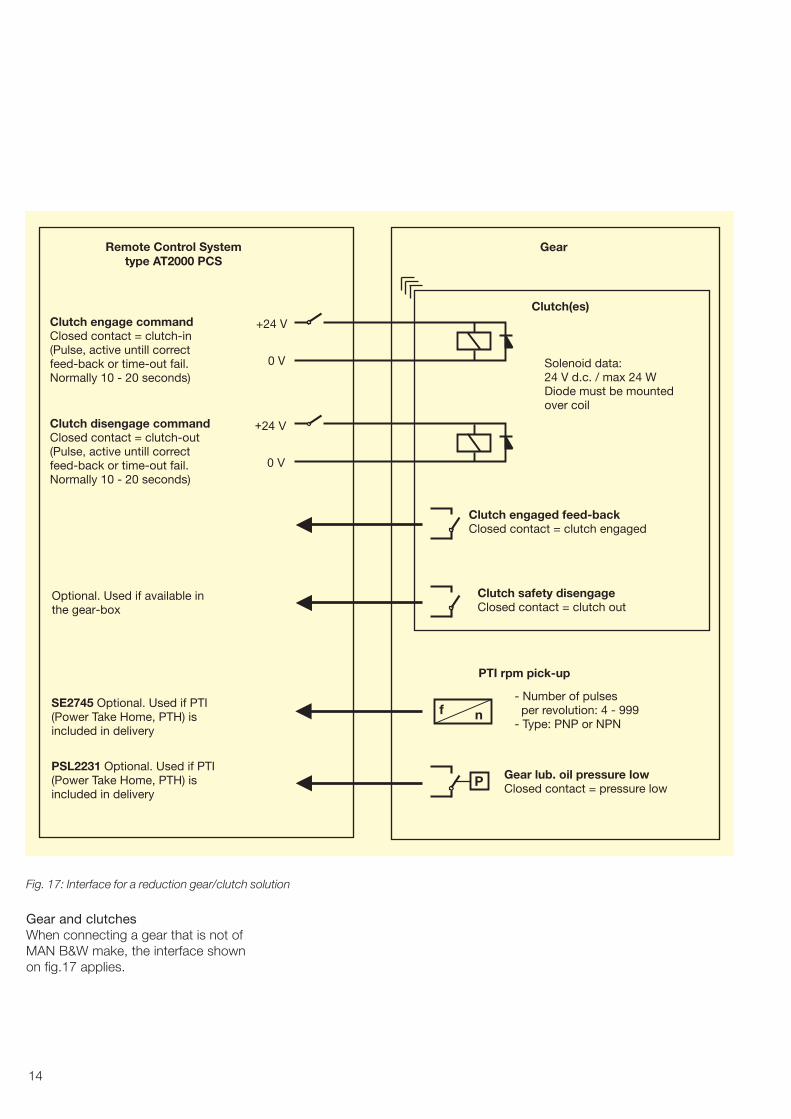
Gear and clutchesWhen connecting a gear that is not ofMAN B&W make, the interface shownon fig.17 applies.
� Number of pulsesper revolution: 4 � 999
� Type: PNP or NPNnfSE2745 Optional. Used if PTI
(Power Take Home, PTH) isincluded in delivery
Clutch safety disengageClosed contact = clutch out
Optional. Used if available inthe gear�box
Clutch engaged feed�backClosed contact = clutch engaged
+24 V
Solenoid data:24 V d.c. / max 24 WDiode must be mountedover coil
0 V
+24 V
0 V
Clutch disengage commandClosed contact = clutch�out(Pulse, active untill correctfeed�back or time�out fail.Normally 10 � 20 seconds)
PTI rpm pick�up
Gear lub. oil pressure lowClosed contact = pressure lowP
PSL2231 Optional. Used if PTI(Power Take Home, PTH) isincluded in delivery
Clutch(es)
GearRemote Control Systemtype AT2000 PCS
Clutch engage commandClosed contact = clutch�in(Pulse, active untill correctfeed�back or time�out fail.Normally 10 � 20 seconds)
Fig. 17: Interface for a reduction gear/clutch solution

15
Shut down systemRemote Control System type AT2000 PCS
ZSI4710, Emergency stoppedContact closed at stopped
SEH1704, Overspeed stoppedContact closed at stopped
SZI4739, Non cancellable shut downContact closed at activated sensor
SZI4740, Cancellable shut downContact closed at activated sensor
SZI4737, Shut down activeContact closed at active shut down
ZSI4735A, Shut down cancelledContact closed at cancelled
ZS4735A, Shut down cancel orderContact closed at cancel
ZS4736A, Shut down reset orderContact closed at reset (pulse, 2 sec.)ZS4710, Emergency stop switchContact closed at shut downSupervision resistor: 10 kohm
ZSI4748, Load reduction cancelledContact closed at cancelled
ZSI4747, Load reduction activeContact closed at active
ZS4747, Automatic load reduction/ slow down request
Contact closed at request
Load reduction / slow down interface Ships alarm system
Fig. 18: Interface for safety system with an engine not of MAN B&W make
Safety systemWhen the engine is not of MAN B&Wmake, neither is the safety system. Fig.18 shows the details of the necessaryinterface between the engine safetysystem and the Alphatronic propulsioncontrol system.

16
Two�stroke diesel engineRemote Control System type AT2000 PCS
ZT1401, Fuel indexTwo wire loop powered orfour wire galvanically separated4 � 20 mA = 0 � 110 % index
PT1331B, Charge air pressureTwo wire loop powered orfour wire galvanically separated4 � 20 mA = 0 � 4 bar
ZSH1401, Engine overload(Fuel index above 100%)Contact closed at overload
SE1704A, Engine speed4 � 20 mA or 0 � 10 V = 120 % mcrGalvanically separated
ZS4714, Engine start command24 V dc, max 1A
ZS4713B, Engine stop command24 V dc, max 1A
ZS4716, Engine slow turn command24 V dc, max 1A
ZS4701, Engine controlled locallyContact closed at local
ZS4702, Engine controlled remoteContact closed at remote
ZS4700A, Emergency controlledContact closed at emergency
ZS4700B, Engine governor engagedContact closed at engaged
ZS1705, Turning gear engagedContact closed at engaged
ZS1313, Main start air valve closedContact closed at closed valve
ZS1314, Start air distributor closedContact closed at closed valve
ZSI1330, Auxiliary blower runningContact closed at running
PSL1321, Control air system ventedContact closed at vented
PSL1322, Safety air system ventedContact closed at vented
or
or
Fig. 19a: Interface for a two-stroke diesel engine not of MAN B&W make
EngineWhen the diesel engine is not of MANB&W make, the interface shown onfig. 19a and 19b applies for a two-stroke engine. Fig. 20 applies for afour-stroke engine.

17
Remote Control System type AT2000 PCS Engine governor
SC1706A, Engine speed order4 � 20 mA = idle to 100%rpmGalvanically separatedMax load resistance: 500 ohm
ZS4713A, Governor stop command24 V dc, max 1A
SC1708, Governor speed enableClosed contact when enabled(Only for pneumatic governor)ZI3725B, Propeller pitch
feed back to governorGalvanically separated(Only for electronic governor)
SC1709, Governor limits cancelClosed contact at cancel
Fig. 19b: Interface for a two-stroke diesel engine not of MAN B&W make

18
Four�stroke diesel engineRemote Control System type AT2000 PCS
ZT1401, Fuel indexTwo wire loop powered orgalvanically separated4 � 20 mA = 0 � 110 % index
PT1331B, Charge air pressureTwo wire loop powered orgalvanically separated4 � 20 mA = 0 � 4 bar
Engine governor
ZSH1401, Engine overload(Fuel index above 100%)Contact closed at overload
SE1704A, Engine speed4 � 20 mA or 0 � 10 V = 120 % mcrGalvanically separated
SC1706A, Engine speed order4 � 20 mA = idle to 100%rpmGalvanically separated
SC1708, Governor speed enableClosed contact when enabled(Only for pneumatic governor)
ZS4701, Engine controlled locallyContact closed at local
ZS4702, Engine controlled remoteContact closed at remote
or
or
Max load: 500 ohm
SC4715, Engine Start BlockingContact Open at Start BlockingContact closed when pitch is zeroand CPP servo pump is running
ZS4714, Engine start commandContact closed at start.Pulse signal, duration 2 secondsZS4714, Engine stop commandContact closed at stopPulse signal, duration 2 secondsZS4709, Engine start failure resetContact closed at resetPulse signal, duration 2 secondsZS4715, Engine start blockedContact closed at blocking
The optional signals below are used when remote start / stop via AT2000�PCS is required butstart and stop sequences are carried out by the engine control system.
Four�stroke diesel enginecontrol system
Remote Control System type AT2000 PCS
Fig 20: Interface for a four-stroke diesel engine not of MAN B&W make
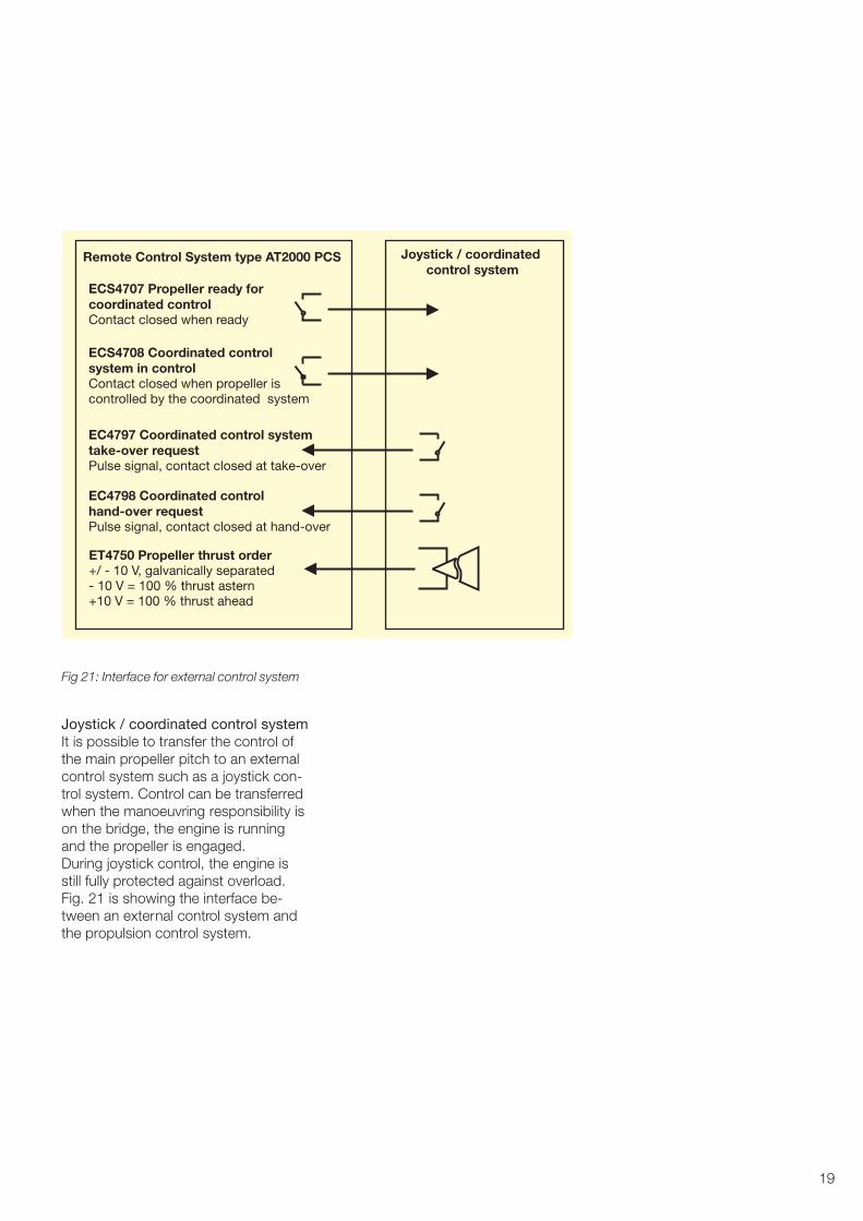
19
Joystick / coordinatedcontrol system
Remote Control System type AT2000 PCS
EC4797 Coordinated control systemtake�over requestPulse signal, contact closed at take�over
EC4798 Coordinated controlhand�over requestPulse signal, contact closed at hand�over
ECS4707 Propeller ready forcoordinated controlContact closed when ready
ECS4708 Coordinated controlsystem in controlContact closed when propeller iscontrolled by the coordinated system
ET4750 Propeller thrust order
� 10 V = 100 % thrust astern+10 V = 100 % thrust ahead
+/ � 10 V, galvanically separated
Fig 21: Interface for external control system
Joystick / coordinated control systemIt is possible to transfer the control ofthe main propeller pitch to an externalcontrol system such as a joystick con-trol system. Control can be transferredwhen the manoeuvring responsibility ison the bridge, the engine is runningand the propeller is engaged.During joystick control, the engine isstill fully protected against overload.Fig. 21 is showing the interface be-tween an external control system andthe propulsion control system.
20
1200
mm
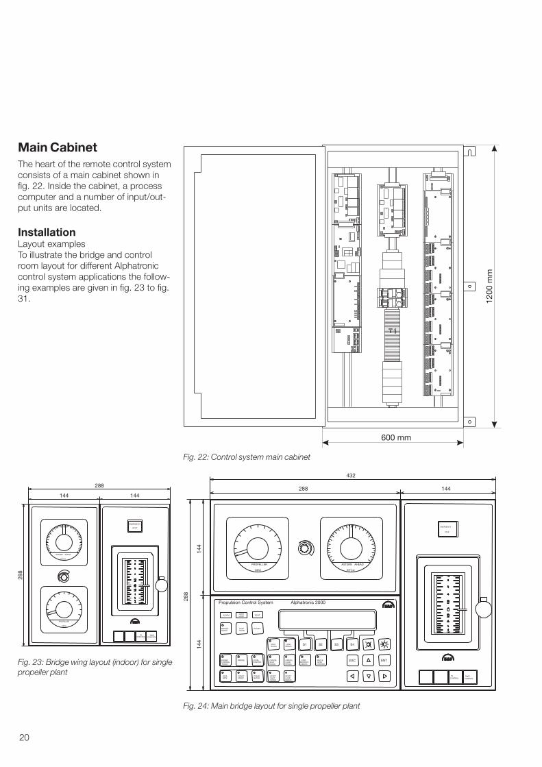
600 mm
Fig. 22: Control system main cabinet
ASTERN AHEAD
PITCH
PROPELLER
RPM
TAKECONTROL
INCONTROL
EMERGENCY
STOP
288
144 144
288
TAKECONTROL
INCONTROL
FAULTOVERLOADALARM
Propulsion Control System Alphatronic 2000
ACCEPTSTOPHORN
MAINTE�NANCE
COMBI�NATOR
CONST.SPEED
SEPA�RATE
LOCALCONTROL
BRIDGEENGINECONTROLROOM
MACHI�NERY
CONTROL
LOADRESTRICTCANCEL
RESETSHUTDOWN
RESETLOADREDUC.
CANCELLOADREDUC.
CANCELSHUTDOWN
LOADREDUC.
SHUTDOWN
S1 S2 S3 S4
ESC ENT
ASTERN AHEAD
PITCH
PROPELLER
RPM
EMERGENCY
STOP
288 144
432
144
144
288
Fig. 23: Bridge wing layout (indoor) for singlepropeller plant
Fig. 24: Main bridge layout for single propeller plant
Main CabinetThe heart of the remote control systemconsists of a main cabinet shown infig. 22. Inside the cabinet, a processcomputer and a number of input/out-put units are located.
InstallationLayout examplesTo illustrate the bridge and controlroom layout for different Alphatroniccontrol system applications the follow-ing examples are given in fig. 23 to fig.31.
21
TAKECONTROL
INCONTROL
FAULTOVERLOADALARM
Propulsion Control System Alphatronic 2000
ACCEPTSTOPHORN
MAINTE�NANCE
COMBI�NATOR
CONST.SPEED
SEPA�RATE
LOCALCONTROL
BRIDGEENGINECONTROLROOM
MACHI�NERY
CONTROL
LOADRESTRICTCANCEL
RESETSHUTDOWN
RESETLOADREDUC.
CANCELLOADREDUC.
CANCELSHUTDOWN
LOADREDUC.
SHUTDOWN
S1 S2 S3 S4
ESC ENT
ASTERN AHEAD
PITCH
PROPELLER
RPM
EMERGENCY
STOP
288 144
432
144
144
288
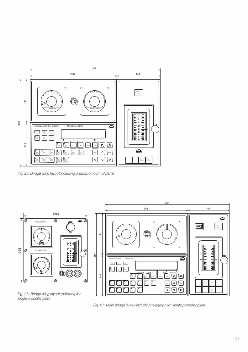
Fig. 26: Bridge wing layout (outdoor) forsingle propeller plant
Propeller RPM
Propeller Pitch
INCONTROL
TAKECONTROL
ST
YC
NE
EM
ER G
O P
288
288
STAND
BY
FINISH
WITH
ENGINEENTESC
S4S3S2S1SHUT
DOWN
LOAD
REDUC.
CANCEL
SHUT
DOWN
CANCEL
LOAD
REDUC.
RESET
LOAD
REDUC.
RESET
SHUT
DOWN
LOAD
RESTRICT
CANCEL
MACHI�
NERY
CONTROL
ENGINE
CONTROL
ROOM
BRIDGE LOCAL
CONTROL
SEPA�
RATE
CONST.
SPEED
COMBI�
NATOR
MAINTE�
NANCE
STOP
HORN
ACCEPT
Propulsion Control System Alphatronic 2000
ALARMOVER
LOADFAULT
ASTERN AHEAD
PITCH
PROPELLER
RPM
EMERGENCY
STOP
TELE�
GRAPH
ON/OFF
ON
SERVICE
288
144
144
432
144288
Fig. 25: Bridge wing layout including propulsion control panel
Fig. 27: Main bridge layout including telegraph for single propeller plant

22
STANDBY
FINISHWITH
ENGINE
TAKECONTROL
INCONTROL
BACK UPCONTROLON/OFF
ENTESC
S4S3S2S1SHUTDOWN
LOADREDUC.
CANCELSHUTDOWN
CANCELLOADREDUC.
RESETLOADREDUC.
RESETSHUTDOWN
LOADRESTRICTCANCEL
MACHI�NERY
CONTROL
ENGINECONTROLROOM
BRIDGE LOCALCONTROL
SEPA�RATE
CONST.SPEED
COMBI�NATOR
MAINTE�NANCE
STOPHORN
ACCEPT
Propulsion Control System Alphatronic 2000
ALARM OVERLOAD FAULT
ASTERN AHEAD
PITCH
PROPELLER
RPM
EMERGENCY
STOP
288
144
144
432
144288
Fig. 28: Engine control room layout including telegraph for single propeller plant
TAKE
CONTROL
IN
CONTROL
BACK�UP
CONTROLON/OFF
ENTESC
S4S3S2S1SHUTDOWN
LOADREDUC.
CANCELSHUTDOWN
CANCELLOADREDUC.
RESETLOADREDUC.
RESETSHUTDOWN
LOADRESTRICTCANCEL
MACHI�NERY
CONTROL
ENGINECONTROLROOM
BRIDGE LOCALCONTROL
SEPA�RATE
CONST.SPEED
COMBI�NATOR
MAINTE�NANCE
STOP
HORNACCEPT
Propulsion Control System Alphatronic 2000
ALARMOVERLOAD
FAULT
ASTERN AHEAD
PITCH
PROPELLER
RPM
EMERGENCY
STOP
288
144
144
432
144288
Fig. 29: Main bridge layout for single propeller plant

23
BACK UP
CONTROL
ON/OFF
ENTESC
S4S3S2S1SHUT
DOWN
LOAD
REDUC.
CANCEL
SHUT
DOWN
CANCEL
LOAD
REDUC.
RESET
LOAD
REDUC.
RESET
SHUT
DOWN
LOAD
RESTRICT
CANCEL
MACHI�
NERY
CONTROL
ENGINE
CONTROL
ROOM
BRIDGE LOCAL
CONTROL
SEPA�
RATE
CONST.
SPEED
COMBI�
NATOR
MAINTE�
NANCE
STOP
HORN
ACCEPT
Propulsion Control System Alphatronic 2000
ALARMOVER
LOADFAULT
ASTERN AHEAD
PITCH
PROPELLER
RPM
EMERGENCY
STOP
TAKE
CONTROL
IN
CONTROL
ASTERN AHEAD
PITCH
ENTESC
S4S3S2S1
BACK UP
CONTROL
ON/OFF
SHUT
DOWN
LOAD
REDUC.
CANCEL
SHUT
DOWN
CANCEL
LOAD
REDUC.
RESET
LOAD
REDUC.
RESET
SHUT
DOWN
LOAD
RESTRICT
CANCEL
MACHI�
NERY
CONTROL
ENGINE
CONTROL
ROOM
BRIDGE LOCAL
CONTROL
SEPA�
RATE
CONST.
SPEED
COMBI�
NATOR
MAINTE�
NANCE
STOP
HORN
ACCEPT
Propulsion Control System Alphatronic 2000
ALARMOVER
LOADFAULT
PROPELLER
RPM
EMERGENCY
STOP
TAKE
CONTROL
IN
CONTROL
288144
144
144
144288
144
864
144
288
Fig. 30: Main bridge layout for double propeller plant
PROPELLER
RPM
ASTERN AHEAD
PITCH
IN
CONTROLTAKE
CONTROL
TAKE
CONTROL
IN
CONTROL
PROPELLER
RPM
ASTERN AHEAD
PITCH
EMERGENCY
STOP
EMERGENCY
STOP
288
144 144
288 288
144 144
Fig. 31: Bridge wing layout for double propeller plant

24
SHIP ALARM SYSTEM
Remote control. Fuse 10A nominal consumption 150WSafety system. Fuse 10A nominel consumption 150W
ESC
W22
6x
1.5
W24
7x
1.5
PCP_MPIP_MMHP_M W15 3x0.75W13 4x0.75
24V DC SUPPLY
2048505�12050070�72052235�0
2048548�2ELECTRIC SHAFT
PROPULSION CTRL.PROPELLER INSTR.MANOEUVRE HANDLE
W49
10
x1.5
W39
10
x1.5
W29
10
x1.5
W19
10
x1.5
BRIDGE AREA
W25 3x0.75 PCP_1
2048505�1PROPULSION CTRL.
FUEL OIL INSTR.
706974�3Q96
W23 4x0.75
W32
6x
1.5
W34
7x
1.5
PIP_1MHP_1
2050070�72052231�3PROPELLER INSTR.MANOEUVRE HANDLE
W8S
2x
0.75
PIP_2MHP_2 W33 4x0.75
2050070�72052231�3PROPELLER INSTR.MANOEUVRE HANDLE
W42
6x
1.5
W44
7x
1.5
PIP_3MHP_3W43 4x0.75
2050070�72052231�3PROPELLER INSTR.MANOEUVRE HANDLE
W18 2x1.5
W28 2x1.5
W17 2x2x0.75 *W16 2x2x0.75 *
W14 7x1.5
W12 6x1.5
W1 4x1.5
W26
2x2
x0.7
5 *
W27
2x2
x0.7
5 *
W5 6x1.5W10 2x0.75
SLAVE 1
MAINBRIDGE
W101 2x2.5W102 2x2.5
W103 4x0.75
2052390�5
SLAVE 2
SLAVE 3
PROPULSION CONTROLSYSTEM
PCS
ENGINE AREA
W7S 2x0.75
GEARX412018448�6
W107 14x0.75
PMS/SWITCH BOARD
NOT MAN B&W SUPPLY
W296 2x0.75
W293 4x1.5
W295 5x0.75W294 12x1.5
TERMINAL BOXX52.1
* Type 3 cable
** Type 2 cable
Other Type 1 cable
2047849�6
The type is specifiedin the InstallationGuidance.
Abbreviations arespecified in2047850�6
W64 8x1.5W63 2x1.5W62 16x1.5W61 2x1.5
WOODWARDSERVO UNITBOX 11
MAIN�ENGINEBOX 1
W73 3x2x0.5 ** SHIP ALARM SYSTEM
W71 12x1.5
W65 3x0.75W66 3x2x0.75 **
W72 10x1.5 STAND�BY PUMP STARTER
MAX. LENGTH 10 M
W75 4x0.5 SHIP ALARM SYSTEM
2052410�0
W74 4x1.5
Fig. 32: Example of cable plan
Cable plansCable plan and connection lists show-ing each cable connection to controlsystem terminals are supplied by MANB&W Alpha – after the Purchase Con-tract has been signed and upon re-ceipt of all necessary shipyard informa-tion.
In order to ensure the optimum func-tion, reliability and safety of the controlsystem, without compromise – the fol-lowing installation requirements mustbe taken into consideration:
• Power supply cables must be at leastof size 2.5 mm2
• If the supply cable length betweenthe bridge and the engine room is inexcess of 60 metres, the voltage dropshould be considered
• The signal cables should have wireswith cross sectional area of min 0.75mm2 and max 1.5 mm2
• All cables should be shielded and thescreen must be connected to earth(terminal boxes) at both ends
• Signal cables are not to be locatedalongside any other power cablesconducting high voltage (ie largemotors etc) or radio communicationcables. The remote control signalscan be disturbed by current in-duced into the cables from their im-mediate environment. Induced cur-rent may disturb or even damagethe electronic control system if thecables are not installed according toour Installation Guidance.

25
Fig. 33: Example of connection list
CommissioningAs part of the on–board acceptanceprocedures, a final system test of theremote control system is carried out byMAN B&W Alpha commissioning engi-neers.A number of Classification Societiesusually require the on–board test to beperformed in the presence of a sur-veyor before the official sea trial. Priorto the functional test, and even beforethe power supply voltage is switchedon – the cable plan and connectionlists are cross–checked with all wiringand connections made by the ship-yard.The MAN B&W Alpha procedure forAlphatronic Remote Control SystemTest is carried out in accordance withan exhaustive check list covering anumber of tasks within the followingcategories:• Power up and control room respon-
sibility• Control panel operations and indica-
tions• Manoeuvre responsibility and trans-
fer• Failure and alarm simulation• Propeller pitch back–up control• Shaft alternator controlThe commissioning engineers will ad-just all lever positions and order signalsas preparation for the fine tuning ofsettings for propeller pitch, fuel indexetc performed during the sea trials.
Instruction ManualAs part of our technical documenta-tion, an instruction manual will be for-warded. The instruction manual is tai-lor–made for each individual controlsystem and includes:• Descriptions and technical data• Operation and maintenance guide
lines• Spare parts plates
The manual can be supplied in two dif-ferent versions – a printed copy as wellas an electronic book in English onCD–ROM.

26