Alpha Customer Application Manual Section 10 - Specifications · Alpha Customer Application Manual...
30
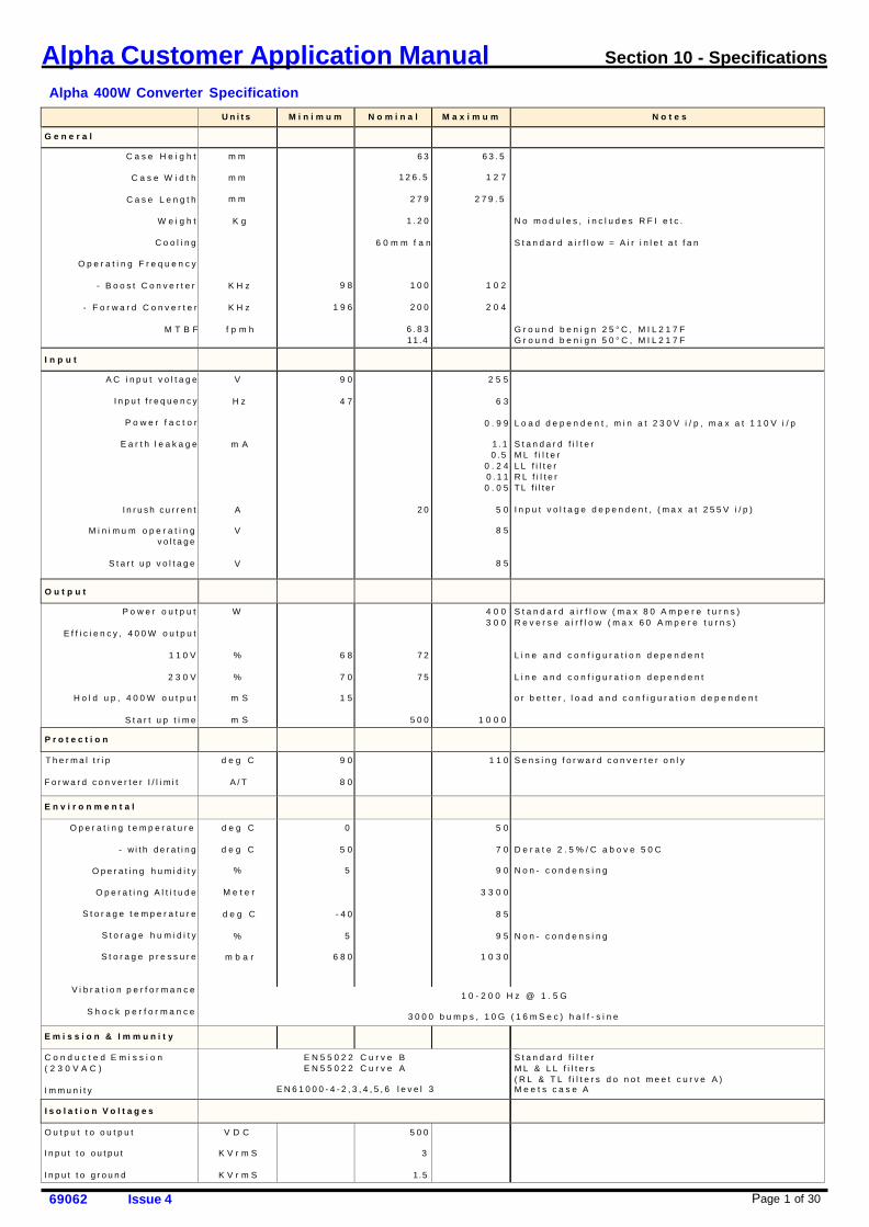
Alpha Customer Application Manual Section 10 - Specifications Alpha 400W Converter Specification Page 1 of 30 69062 Issue 4 Units Minimum Nominal M a x i m u m N o t e s General C a s e H e i g h t C a s e W i d t h Case Length Weight Cooling Operating Frequency - B o o s t C o n v e r t e r - Forward Converter M T B F mm mm mm K g KHz KHz f p m h 9 8 196 63 126.5 279 1.20 6 0 m m f a n 100 200 6.83 11.4 63.5 1 2 7 279.5 1 0 2 2 0 4 N o m o d u l e s , i n c l u d e s R F I e t c . S t a n d a r d a i r f l o w = A i r i n l e t a t f a n G r o u n d b e n i g n 2 5 ° C , M I L 2 1 7 F G r o u n d b e n i g n 5 0 ° C , M I L 2 1 7 F I n p u t A C i n p u t v o l t a g e Input frequency P o w e r f a c t o r E a r t h l e a k a g e Inrush current M i n i m u m o p e r a t i n g voltage Start up voltage V Hz m A A V V 9 0 4 7 20 2 5 5 6 3 0.99 1.1 0.5 0.24 0.11 0.05 5 0 8 5 8 5 L o a d d e p e n d e n t , m i n a t 2 3 0 V i / p , m a x a t 1 1 0 V i / p Standard filter ML filter LL filter R L f i l t e r TL filter I n p u t v o l t a g e d e p e n d e n t , ( m a x a t 2 5 5 V i / p ) Output Power output Efficiency, 400W output 110V 230V Hold up, 400W output S t a r t u p t i m e W % % m S m S 6 8 7 0 1 5 72 75 500 4 0 0 3 0 0 1 0 0 0 S t a n d a r d a i r f l o w ( m a x 8 0 A m p e r e t u r n s ) Reverse airflow (max 60 Ampere turns) Line and configuration dependent Line and configuration dependent o r b e t t e r , l o a d a n d c o n f i g u r a t i o n d e p e n d e n t Protection Thermal trip Forward converter I/limit d e g C A/T 9 0 8 0 110 Sensing forward converter only Environmental Operating temperature - with derating Operating humidity Operating Altitude Storage temperature Storage humidity Storage pressure Vibration performance S h o c k p e r f o r m a n c e d e g C d e g C % Meter d e g C % m b a r 0 5 0 5 -40 5 680 5 0 7 0 9 0 3 3 0 0 8 5 9 5 1 0 3 0 D e r a t e 2 . 5 % / C a b o v e 5 0 C Non- condensing Non- condensing 10-200 Hz @ 1.5G 3 0 0 0 b u m p s , 1 0 G ( 1 6 m S e c ) h a l f - s i n e E m i s s i o n & I m m u n i t y C o n d u c t e d E m i s s i o n ( 2 3 0 V A C ) Immunity E N 5 5 0 2 2 C u r v e B E N 5 5 0 2 2 C u r v e A EN61000-4-2,3,4,5,6 level 3 Standard filter M L & L L f i l t e r s ( R L & T L f i l t e r s d o n o t m e e t c u r v e A ) M e e t s c a s e A I s o l a t i o n V o l t a g e s O u t p u t t o o u t p u t Input to output Input to ground V D C K V r m S K V r m S 500 3 1.5
Transcript of Alpha Customer Application Manual Section 10 - Specifications · Alpha Customer Application Manual...
Alpha Customer Application Manual Section 10 - Specifications
Alpha 400W Converter Specification
Page 1 of 30 69062 Issue 4
U n i t s M i n i m u m N o m i n a l M a x i m u m N o t e s
G e n e r a l C a s e H e i g h t
C a s e W i d t h
C a s e L e n g t h
W e i g h t
C o o l i n g
O p e r a t i n g F r e q u e n c y
- B o o s t C o n v e r t e r
- F o r w a r d C o n v e r t e r
M T B F
m m
m m
m m
K g
K H z
K H z
f p m h
9 8
1 9 6
6 3
1 2 6 . 5
2 7 9
1 . 2 0
6 0 m m f a n
1 0 0
2 0 0
6 . 8 3 11 .4
6 3 . 5
1 2 7
2 7 9 . 5
1 0 2
2 0 4
N o m o d u l e s , i n c l u d e s R F I e t c .
S t a n d a r d a i r f l o w = A i r i n l e t a t f a n
G r o u n d b e n i g n 2 5 ° C , M I L 2 1 7 F G r o u n d b e n i g n 5 0 ° C , M I L 2 1 7 F
I n p u t A C i n p u t v o l t a g e
I n p u t f r e q u e n c y
P o w e r f a c t o r
E a r t h l e a k a g e
I n r u s h c u r r e n t
M i n i m u m o p e r a t i n g v o l t a g e
S t a r t u p v o l t a g e
V
H z
m A
A
V
V
9 0
4 7
2 0
2 5 5
6 3
0 . 9 9
1 . 1 0 . 5
0 . 2 4 0 . 1 1 0 . 0 5
5 0
8 5
8 5
L o a d d e p e n d e n t , m i n a t 2 3 0 V i / p , m a x a t 1 1 0 V i / p
S t a n d a r d f i l t e r M L f i l t e r L L f i l t e r R L f i l t e r T L f i l t e r
I n p u t v o l t a g e d e p e n d e n t , ( m a x a t 2 5 5 V i / p )
O u t p u t
P o w e r o u t p u t
E f f i c i e n c y , 4 0 0 W o u t p u t
1 1 0 V
2 3 0 V
H o l d u p , 4 0 0 W o u t p u t
S t a r t u p t i m e
W
%
%
m S
m S
6 8
7 0
1 5
7 2
7 5
5 0 0
4 0 0 3 0 0
1 0 0 0
S t a n d a r d a i r f l o w ( m a x 8 0 A m p e r e t u r n s ) R e v e r s e a i r f l o w ( m a x 6 0 A m p e r e t u r n s )
L i n e a n d c o n f i g u r a t i o n d e p e n d e n t
L i n e a n d c o n f i g u r a t i o n d e p e n d e n t
o r b e t t e r , l o a d a n d c o n f i g u r a t i o n d e p e n d e n t
P r o t e c t i o n T h e r m a l t r i p
F o r w a r d c o n v e r t e r I / l i m i t
d e g C
A / T
9 0
8 0
1 1 0 S e n s i n g f o r w a r d c o n v e r t e r o n l y
E n v i r o n m e n t a l O p e r a t i n g t e m p e r a t u r e
- w i t h d e r a t i n g
O p e r a t i n g h u m i d i t y
O p e r a t i n g A l t i t u d e
S t o r a g e t e m p e r a t u r e
S t o r a g e h u m i d i t y
S t o r a g e p r e s s u r e
V i b r a t i o n p e r f o r m a n c e
S h o c k p e r f o r m a n c e
d e g C
d e g C
%
M e t e r
d e g C
%
m b a r
0
5 0
5
- 4 0
5
6 8 0
5 0
7 0
9 0
3 3 0 0
8 5
9 5
1 0 3 0
D e r a t e 2 . 5 % / C a b o v e 5 0 C
N o n - c o n d e n s i n g
N o n - c o n d e n s i n g
1 0 - 2 0 0 H z @ 1 . 5 G
3 0 0 0 b u m p s , 1 0 G ( 1 6 m S e c ) h a l f - s i n e
E m i s s i o n & I m m u n i t y C o n d u c t e d E m i s s i o n ( 2 3 0 V A C )
I m m u n i t y
E N 5 5 0 2 2 C u r v e B E N 5 5 0 2 2 C u r v e A
E N 6 1 0 0 0 - 4 - 2 , 3 , 4 , 5 , 6 l e v e l 3
S t a n d a r d f i l t e r M L & L L f i l t e r s ( R L & T L f i l t e r s d o n o t m e e t c u r v e A ) M e e t s c a s e A
I s o l a t i o n V o l t a g e s O u t p u t t o o u t p u t
I n p u t t o o u t p u t
I n p u t t o g r o u n d
V D C
K V r m S
K V r m S
5 0 0
3
1.5
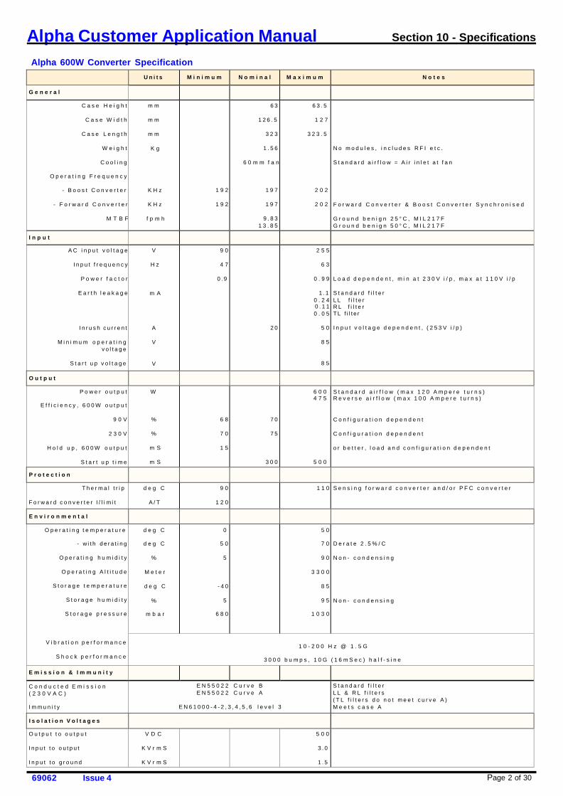
Page 2 of 30 69062 Issue 4
Alpha Customer Application Manual Section 10 - Specifications
Alpha 600W Converter Specification
U n i t s M i n i m u m N o m i n a l M a x i m u m N o t e s
G e n e r a l C a s e H e i g h t
C a s e W i d t h
C a s e L e n g t h
W e i g h t
C o o l i n g
O p e r a t i n g F r e q u e n c y
- B o o s t C o n v e r t e r
- F o r w a r d C o n v e r t e r
M T B F
m m
m m
m m
K g
K H z
K H z
f p m h
1 9 2
1 9 2
6 3
1 2 6 . 5
3 2 3
1 . 5 6
6 0 m m f a n
1 9 7
1 9 7
9 . 8 3 1 3 . 8 5
6 3 . 5
1 2 7
3 2 3 . 5
2 0 2
2 0 2
N o m o d u l e s , i n c l u d e s R F I e t c .
S t a n d a r d a i r f l o w = A i r i n l e t a t f a n
F o r w a r d C o n v e r t e r & B o o s t C o n v e r t e r S y n c h r o n i s e d
G r o u n d b e n i g n 2 5 ° C , M I L 2 1 7 F G r o u n d b e n i g n 5 0 ° C , M I L 2 1 7 F
I n p u t A C i n p u t v o l t a g e
I n p u t f r e q u e n c y
P o w e r f a c t o r
E a r t h l e a k a g e
I n r u s h c u r r e n t
M i n i m u m o p e r a t i n g v o l t a g e
S t a r t u p v o l t a g e
V
H z
m A
A
V
V
9 0
4 7
0 . 9
2 0
2 5 5
6 3
0 . 9 9
1 . 1 0 . 2 4 0 . 1 1 0 . 0 5
5 0
8 5
8 5
L o a d d e p e n d e n t , m i n a t 2 3 0 V i / p , m a x a t 1 1 0 V i / p
S t a n d a r d f i l t e r L L f i l t e r R L f i l t e r T L f i l t e r
I n p u t v o l t a g e d e p e n d e n t , ( 2 5 3 V i / p )
O u t p u t P o w e r o u t p u t
E f f i c i e n c y , 6 0 0 W o u t p u t
9 0 V
2 3 0 V
H o l d u p , 6 0 0 W o u t p u t
S t a r t u p t i m e
W
%
%
m S
m S
6 8
7 0
1 5
7 0
7 5
3 0 0
6 0 0 4 7 5
5 0 0
S t a n d a r d a i r f l o w ( m a x 1 2 0 A m p e r e t u r n s ) R e v e r s e a i r f l o w ( m a x 1 0 0 A m p e r e t u r n s )
C o n f i g u r a t i o n d e p e n d e n t
C o n f i g u r a t i o n d e p e n d e n t
o r b e t t e r , l o a d a n d c o n f i g u r a t i o n d e p e n d e n t
P r o t e c t i o n T h e r m a l t r i p
F o r w a r d c o n v e r t e r I / l i m i t
d e g C
A / T
9 0
1 2 0
1 1 0 S e n s i n g f o r w a r d c o n v e r t e r a n d / o r P F C c o n v e r t e r
E n v i r o n m e n t a l O p e r a t i n g t e m p e r a t u r e
- w i t h d e r a t i n g
O p e r a t i n g h u m i d i t y
O p e r a t i n g A l t i t u d e
S t o r a g e t e m p e r a t u r e
S t o r a g e h u m i d i t y
S t o r a g e p r e s s u r e
V i b r a t i o n p e r f o r m a n c e
S h o c k p e r f o r m a n c e
d e g C
d e g C
%
M e t e r
d e g C
%
m b a r
0
5 0
5
- 4 0
5
6 8 0
5 0
7 0
9 0
3 3 0 0
8 5
9 5
1 0 3 0
D e r a t e 2 . 5 % / C
N o n - c o n d e n s i n g
N o n - c o n d e n s i n g
1 0 - 2 0 0 H z @ 1 . 5 G
3 0 0 0 b u m p s , 1 0 G ( 1 6 m S e c ) h a l f - s i n e
E m i s s i o n & I m m u n i t y C o n d u c t e d E m i s s i o n ( 2 3 0 V A C )
I m m u n i t y
E N 5 5 0 2 2 C u r v e B E N 5 5 0 2 2 C u r v e A
E N 6 1 0 0 0 - 4 - 2 , 3 , 4 , 5 , 6 l e v e l 3
S t a n d a r d f i l t e r L L & R L f i l t e r s ( T L f i l t e r s d o n o t m e e t c u r v e A ) M e e t s c a s e A
I s o l a t i o n V o l t a g e s O u t p u t t o o u t p u t
I n p u t t o o u t p u t
I n p u t t o g r o u n d
V D C
K V r m S
K V r m S
5 0 0
3 . 0
1 . 5
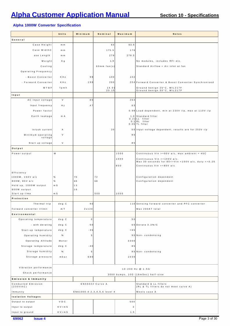
Page 3 of 30 69062 Issue 4
Alpha Customer Application Manual Section 10 - Specifications
Alpha 1000W Converter Specification
U n i t s M i n i m u m N o m i n a l M a x i m u m N o t e s
G e n e r a l C a s e H e i g h t
C a s e W i d t h C
a s e L e n g t h
W e i g h t
C o o l i n g
O p e r a t i n g F r e q u e n c y
- B o o s t C o n v e r t e r
- F o r w a r d C o n v e r t e r
M T B F
m m
m m
m m
K g
K H z
K H z
f p m h
9 8
1 9 6
6 3
1 7 5 . 5
2 7 9
1 . 9
6 0 m m f a n ( s )
1 0 0
2 0 0
1 4 . 0 1 2 3 . 1 5
6 3 . 5
1 7 6
2 7 9 . 5
1 0 2
2 0 4
N o m o d u l e s , i n c l u d e s R F I e t c .
S t a n d a r d A i r f l o w = A i r i n l e t a t f a n
F o r w a r d C o n v e r t e r & B o o s t C o n v e r t e r S y n c h r o n i s e d
G r o u n d b e n i g n 2 5 ° C , M I L 2 1 7 F G r o u n d b e n i g n 5 0 ° C , M I L 2 1 7 F
I n p u t A C i n p u t v o l t a g e
I n p u t f r e q u e n c y
P o w e r f a c t o r
E a r t h l e a k a g e
I n r u s h c u r r e n t
M i n i m u m o p e r a t i n g v o l t a g e
S t a r t u p v o l t a g e
V
H z
m A
A
V
V
8 5
4 7
2 0
2 6 4
6 3
0 . 9 9
1 . 0 0 . 2 1
0 . 1 0 . 0 5
5 0
8 5
8 5
L o a d d e p e n d e n t , m i n a t 2 3 0 V i / p , m a x a t 1 1 0 V i / p
S t a n d a r d f i l t e r L L f i l t e r R L f i l t e r T L f i l t e r
I n p u t v o l t a g e d e p e n d e n t , r e s u l t s a r e f o r 2 5 3 V i / p
O u t p u t P o w e r o u t p u t
E f f i c i e n c y
1 0 0 0 W , 1 5 0 V a / c
8 0 0 W , 8 5 V a / c
H o l d u p , 1 0 0 0 W o u t p u t
8 0 0 W o u t p u t
S t a r t u p t i m e
W %
%
m S
m S
7 0
6 5
1 3
1 6
7 2
6 8
5 0 0
1 0 0 0 1 0 0 0
8 0 0
1 0 0 0
C o n t i n u o u s V i n > = 9 0 V a / c , m a x a m b i e n t = 4 5 C C o n t i n u o u s V i n > = 1 0 0 V a / c . M a x 3 0 s e c o n d s f o r 8 5 < = V i n < 1 5 0 V a / c , d u t y < = 0 . 2 5
C o n t i n u o u s V i n > = 8 5 V a / c C o n f i g u r a t i o n d e p e n d e n t
C o n f i g u r a t i o n d e p e n d e n t
P r o t e c t i o n T h e r m a l t r i p
F o r w a r d c o n v e r t e r I / l i m i t
d e g C
A / T
9 0
2 x 1 2 0
1 1 0 S e n s i n g f o r w a r d c o n v e r t e r a n d P F C c o n v e r t e r M a x 2 0 0 A T t o t a l
E n v i r o n m e n t a l O p e r a t i n g t e m p e r a t u r e
- w i t h d e r a t i n g
S t a r t - u p t e m p e r a t u r e
O p e r a t i n g h u m i d i t y
O p e r a t i n g A l t i t u d e
S t o r a g e t e m p e r a t u r e
S t o r a g e h u m i d i t y
S t o r a g e p r e s s u r e
V i b r a t i o n p e r f o r m a n c e
S h o c k p e r f o r m a n c e
d e g C
d e g C
d e g C
%
M e t e r
d e g C
%
m b a r
0
5 0
- 3 5
5
- 4 0
5
6 8 0
5 0
6 5
+ 6 5
9 0
3 3 0 0
8 5
9 5
1 0 3 0
D e r a t e 3 . 3 % / C
N o n - c o n d e n s i n g
N o n - c o n d e n s i n g
1 0 - 2 0 0 H z @ 1 . 5 G
3 0 0 0 b u m p s , 1 0 G ( 1 6 m S e c ) h a l f - s i n e
E m i s s i o n & I m m u n i t y C o n d u c t e d E m i s s i o n ( 2 3 0 V A C )
I m m u n i t y
E N 5 5 0 2 2 C u r v e A
E N 6 1 0 0 0 - 4 - 2 , 3 , 4 , 5 , 6 l e v e l 4
S t a n d a r d & L L f i l t e r s ( R L & T L f i l t e r s d o n o t m e e t c u r v e A )
M e e t s c a s e A
I s o l a t i o n V o l t a g e s O u t p u t t o o u t p u t
I n p u t t o o u t p u t
I n p u t t o g r o u n d
V D C
K V r m S
K V r m S
5 0 0
3
1 . 5
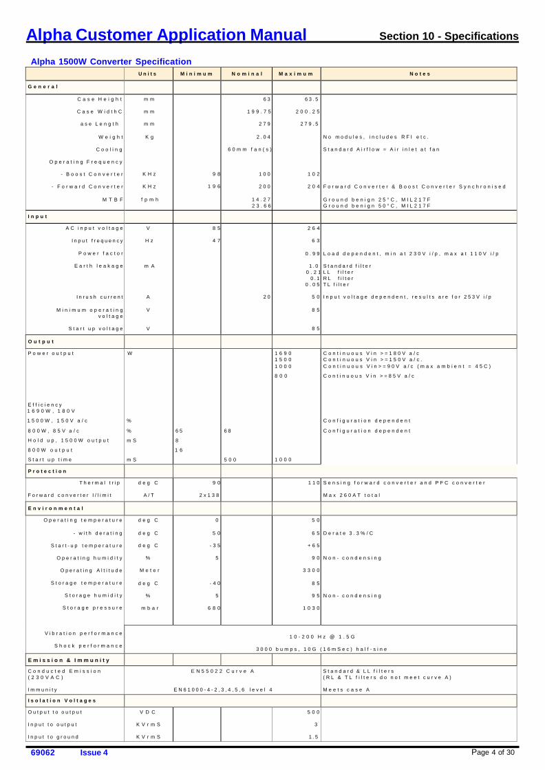
Page 4 of 30 69062 Issue 4
Alpha Customer Application Manual Section 10 - Specifications
Alpha 1500W Converter Specification
U n i t s M i n i m u m N o m i n a l M a x i m u m N o t e s
G e n e r a l C a s e H e i g h t
C a s e W i d t h C
a s e L e n g t h
W e i g h t
C o o l i n g
O p e r a t i n g F r e q u e n c y
- B o o s t C o n v e r t e r
- F o r w a r d C o n v e r t e r
M T B F
m m
m m
m m
K g
K H z
K H z
f p m h
9 8
1 9 6
6 3
1 9 9 . 7 5
2 7 9
2 . 0 4
6 0 m m f a n ( s )
1 0 0
2 0 0
1 4 . 2 7 2 3 . 6 6
6 3 . 5
2 0 0 . 2 5
2 7 9 . 5
1 0 2
2 0 4
N o m o d u l e s , i n c l u d e s R F I e t c .
S t a n d a r d A i r f l o w = A i r i n l e t a t f a n
F o r w a r d C o n v e r t e r & B o o s t C o n v e r t e r S y n c h r o n i s e d
G r o u n d b e n i g n 2 5 ° C , M I L 2 1 7 F G r o u n d b e n i g n 5 0 ° C , M I L 2 1 7 F
I n p u t A C i n p u t v o l t a g e
I n p u t f r e q u e n c y
P o w e r f a c t o r
E a r t h l e a k a g e
I n r u s h c u r r e n t
M i n i m u m o p e r a t i n g v o l t a g e
S t a r t u p v o l t a g e
V
H z
m A
A
V
V
8 5
4 7
2 0
2 6 4
6 3
0 . 9 9
1 . 0 0 . 2 1
0 . 1 0 . 0 5
5 0
8 5
8 5
L o a d d e p e n d e n t , m i n a t 2 3 0 V i / p , m a x a t 1 1 0 V i / p
S t a n d a r d f i l t e r L L f i l t e r R L f i l t e r T L f i l t e r
I n p u t v o l t a g e d e p e n d e n t , r e s u l t s a r e f o r 2 5 3 V i / p
O u t p u t P o w e r o u t p u t
E f f i c i e n c y 1 6 9 0 W , 1 8 0 V
1 5 0 0 W , 1 5 0 V a / c
8 0 0 W , 8 5 V a / c
H o l d u p , 1 5 0 0 W o u t p u t
8 0 0 W o u t p u t
S t a r t u p t i m e
W %
%
m S
m S
6 5
8
1 6
6 8
5 0 0
1 6 9 0 1 5 0 0 1 0 0 0
8 0 0
1 0 0 0
C o n t i n u o u s V i n > = 1 8 0 V a / c C o n t i n u o u s V i n > = 1 5 0 V a / c . C o n t i n u o u s V i n > = 9 0 V a / c ( m a x a m b i e n t = 4 5 C )
C o n t i n u o u s V i n > = 8 5 V a / c
C o n f i g u r a t i o n d e p e n d e n t
C o n f i g u r a t i o n d e p e n d e n t
P r o t e c t i o n T h e r m a l t r i p
F o r w a r d c o n v e r t e r I / l i m i t
d e g C
A / T
9 0
2 x 1 3 8
1 1 0 S e n s i n g f o r w a r d c o n v e r t e r a n d P F C c o n v e r t e r M a x 2 6 0 A T t o t a l
E n v i r o n m e n t a l O p e r a t i n g t e m p e r a t u r e
- w i t h d e r a t i n g
S t a r t - u p t e m p e r a t u r e
O p e r a t i n g h u m i d i t y
O p e r a t i n g A l t i t u d e
S t o r a g e t e m p e r a t u r e
S t o r a g e h u m i d i t y
S t o r a g e p r e s s u r e
V i b r a t i o n p e r f o r m a n c e
S h o c k p e r f o r m a n c e
d e g C
d e g C
d e g C
%
M e t e r
d e g C
%
m b a r
0
5 0
- 3 5
5
- 4 0
5
6 8 0
5 0
6 5
+ 6 5
9 0
3 3 0 0
8 5
9 5
1 0 3 0
D e r a t e 3 . 3 % / C
N o n - c o n d e n s i n g
N o n - c o n d e n s i n g
1 0 - 2 0 0 H z @ 1 . 5 G
3 0 0 0 b u m p s , 1 0 G ( 1 6 m S e c ) h a l f - s i n e
E m i s s i o n & I m m u n i t y C o n d u c t e d E m i s s i o n ( 2 3 0 V A C )
I m m u n i t y
E N 5 5 0 2 2 C u r v e A
E N 6 1 0 0 0 - 4 - 2 , 3 , 4 , 5 , 6 l e v e l 4
S t a n d a r d & L L f i l t e r s ( R L & T L f i l t e r s d o n o t m e e t c u r v e A )
M e e t s c a s e A
I s o l a t i o n V o l t a g e s O u t p u t t o o u t p u t
I n p u t t o o u t p u t
I n p u t t o g r o u n d
V D C
K V r m S
K V r m S
5 0 0
3
1 . 5
Page 5 of 30 69062 Issue 4
Alpha Customer Application Manual Section 10 - Specifications
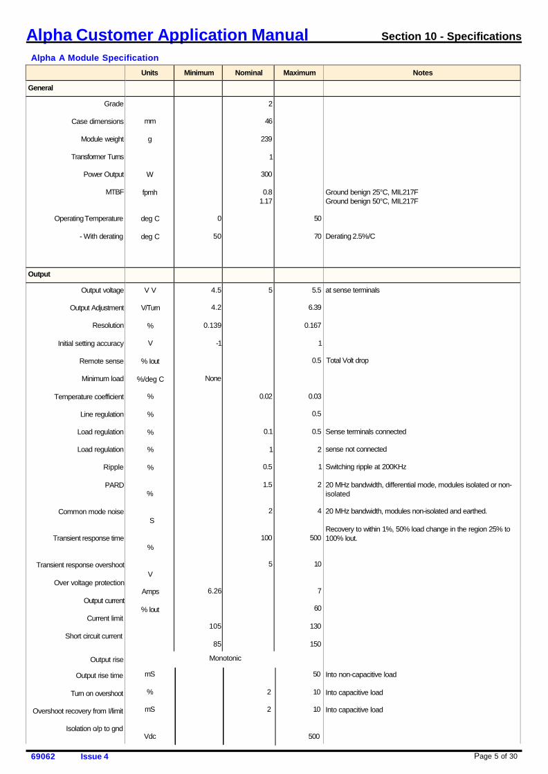
Alpha A Module Specification
Units Minimum Nominal Maximum Notes
General Grade
Case dimensions
Module weight
Transformer Turns
Power Output
MTBF
Operating Temperature
- With derating
mm
g
W
fpmh
deg C
deg C
0
50
2
46
239
1
300
0.8 1.17
50
70
Ground benign 25°C, MIL217F Ground benign 50°C, MIL217F
Derating 2.5%/C
Output Output voltage
Output Adjustment
Resolution
Initial setting accuracy
Remote sense
Minimum load
Temperature coefficient
Line regulation
Load regulation
Load regulation
Ripple
PARD
Common mode noise
Transient response time
Transient response overshoot
Over voltage protection
Output current
Current limit
Short circuit current
Output rise
Output rise time
Turn on overshoot
Overshoot recovery from I/limit
Isolation o/p to gnd
V V
V/Turn
%
V
% Iout
%/deg C
%
%
%
%
%
%
S
%
V
Amps
% lout
4.5
4.2
0.139
-1
None
6.26
105
85
5
0.02
0.1
1
0.5
1.5
2
100
5
5.5
6.39
0.167
1
0.5
0.03
0.5
0.5
2
1
2
4
500
10
7
60
130
150
at sense terminals Total Volt drop
Sense terminals connected
sense not connected
Switching ripple at 200KHz
20 MHz bandwidth, differential mode, modules isolated or non- isolated
20 MHz bandwidth, modules non-isolated and earthed.
Recovery to within 1%, 50% load change in the region 25% to 100% lout.
Into non-capacitive load
Into capacitive load
Into capacitive load
Monotonic
mS 50
% 2 10
mS 2 10
Vdc 500
Page 6 of 30 69062 Issue 4
Alpha Customer Application Manual Section 10 - Specifications
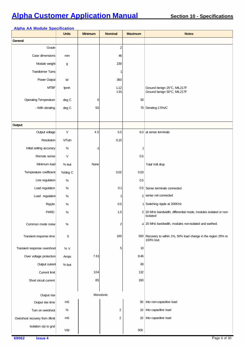
Alpha AA Module Specification
Units Minimum Nominal Maximum Notes
General Grade
Case dimensions
Module weight
Transformer Turns
Power Output
MTBF
Operating Temperature
- With derating
mm
g
W
fpmh
deg C
deg C
0
50
2
46
239
1
360
1.12 1.91
50
70
Ground benign 25°C, MIL217F Ground benign 50°C, MIL217F
Derating 2.5%/C
Output Output voltage
Resolution
Initial setting accuracy
Remote sense
Minimum load
Temperature coefficient
Line regulation
Load regulation
Load regulation
Ripple
PARD
Common mode noise
Transient response time
Transient response overshoot
Over voltage protection
Output current
Current limit
Short circuit current
Output rise
Output rise time
Turn on overshoot
Overshoot recovery from I/limit
Isolation o/p to gnd
V
V/Turn
%
V
% Iout
%/deg C
%
%
%
%
%
%
S
% V
Amps
% lout
4.5
-1
None
7.61
104
85
5.5
0.15
0.02
0.1
1
0.5
1.5
2
100
5
6.0
1
0.5
0.03
0.5
0.5
2
1
2
4
500
10
8.46
60
132
160
at sense terminals
Total Volt drop
Sense terminals connected
sense not connected
Switching ripple at 200KHz
20 MHz bandwidth, differential mode, modules isolated or non- isolated
20 MHz bandwidth, modules non-isolated and earthed.
Recovery to within 1%, 50% load change in the region 25% to 100% lout.
Into non-capacitive load Into capacitive load
Into capacitive load
Monotonic
mS 50
% 2 10
mS 2 10
Vdc 500
Page 7 of 30 69062 Issue 4
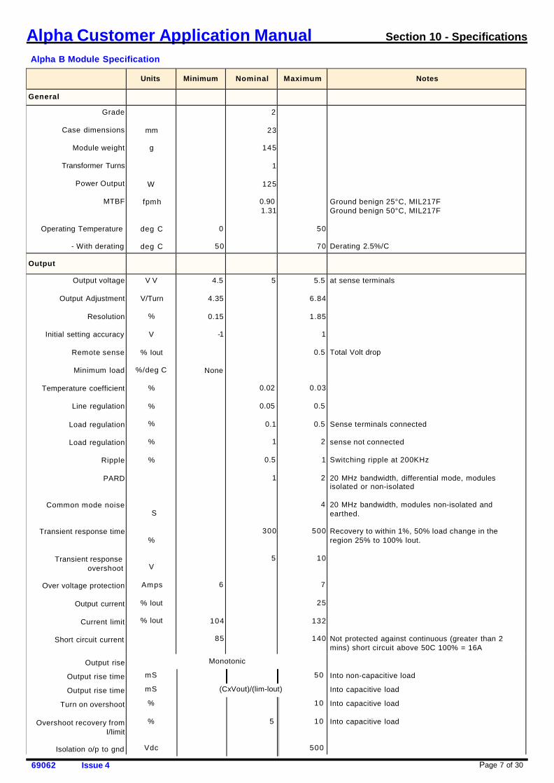
Alpha Customer Application Manual Section 10 - Specifications
Alpha B Module Specification
Units
Minimum
Nominal
Maximum
Notes
General Grade
Case dimensions
Module weight
Transformer Turns
Power Output
MTBF
Operating Temperature
- With derating
mm
g
W
fpmh
deg C
deg C
0
50
2
23
145
1
125
0.90 1.31
50
70
Ground benign 25°C, MIL217F Ground benign 50°C, MIL217F
Derating 2.5%/C
Output
Output voltage
Output Adjustment
Resolution
Initial setting accuracy
Remote sense
Minimum load
Temperature coefficient
Line regulation
Load regulation
Load regulation
Ripple
PARD
Common mode noise
Transient response time
Transient response overshoot
Over voltage protection
Output current
Current limit
Short circuit current
Output rise
Output rise time
Output rise time
Turn on overshoot
Overshoot recovery from I/limit
Isolation o/p to gnd
V V
V/Turn
%
V
% Iout
%/deg C
%
%
%
%
%
S
%
V
Amps
% lout
% lout
4.5
4.35
0.15
-1
None
6
104
85
5
0.02
0.05
0.1
1
0.5
1
300
5
5.5
6.84
1.85
1
0.5
0.03
0.5
0.5
2
1
2
4
500
10
7
25
132
140
at sense terminals Total Volt drop
Sense terminals connected
sense not connected
Switching ripple at 200KHz
20 MHz bandwidth, differential mode, modules isolated or non-isolated
20 MHz bandwidth, modules non-isolated and earthed.
Recovery to within 1%, 50% load change in the region 25% to 100% lout.
Not protected against continuous (greater than 2 mins) short circuit above 50C 100% = 16A
Into non-capacitive load
Into capacitive load
Into capacitive load
Into capacitive load
Monotonic
mS 50
mS (CxVout)/(lim-lout)
% 10
% 5 10
Vdc 500
Page 8 of 30 69062 Issue 4
Alpha Customer Application Manual Section 10 - Specifications
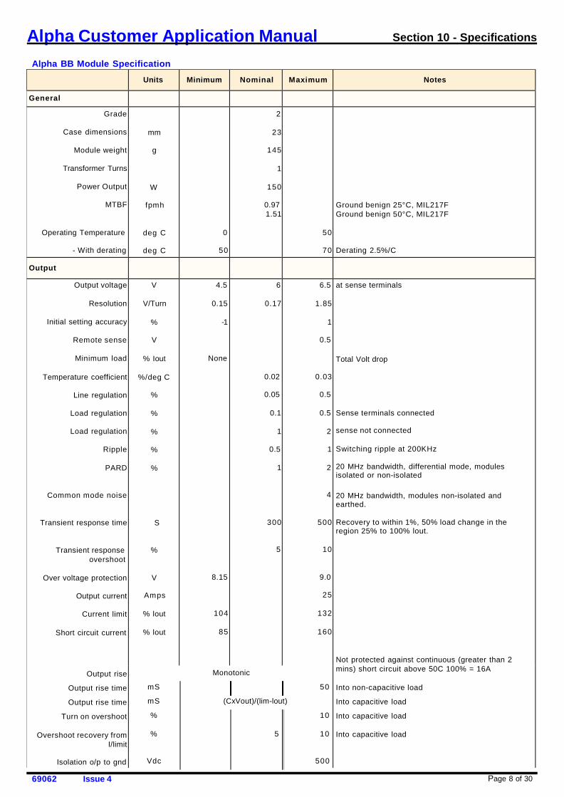
Alpha BB Module Specification
Units
Minimum
Nominal
Maximum
Notes
General Grade
Case dimensions
Module weight
Transformer Turns
Power Output
MTBF
Operating Temperature
- With derating
mm
g
W
fpmh
deg C
deg C
0
50
2
23
145
1
150
0.97 1.51
50
70
Ground benign 25°C, MIL217F Ground benign 50°C, MIL217F
Derating 2.5%/C
Output
Output voltage
Resolution
Initial setting accuracy
Remote sense
Minimum load
Temperature coefficient
Line regulation
Load regulation
Load regulation
Ripple
PARD
Common mode noise
Transient response time
Transient response overshoot
Over voltage protection
Output current
Current limit
Short circuit current
Output rise
Output rise time
Output rise time
Turn on overshoot
Overshoot recovery from I/limit
Isolation o/p to gnd
V
V/Turn
%
V
% Iout
%/deg C
%
%
%
%
%
S
%
V
Amps
% lout
% lout
4.5
0.15
-1
None
8.15
104
85
6
0.17
0.02
0.05
0.1
1
0.5
1
300
5
6.5
1.85
1
0.5
0.03
0.5
0.5
2
1
2
4
500
10
9.0
25
132
160
at sense terminals
Total Volt drop
Sense terminals connected
sense not connected
Switching ripple at 200KHz
20 MHz bandwidth, differential mode, modules isolated or non-isolated
20 MHz bandwidth, modules non-isolated and earthed.
Recovery to within 1%, 50% load change in the region 25% to 100% lout.
Not protected against continuous (greater than 2 mins) short circuit above 50C 100% = 16A
Into non-capacitive load
Into capacitive load
Into capacitive load
Into capacitive load
Monotonic
mS 50
mS (CxVout)/(lim-lout)
% 10
% 5 10
Vdc 500
Page 9 of 30 69062 Issue 4
Alpha Customer Application Manual Section 10 - Specifications
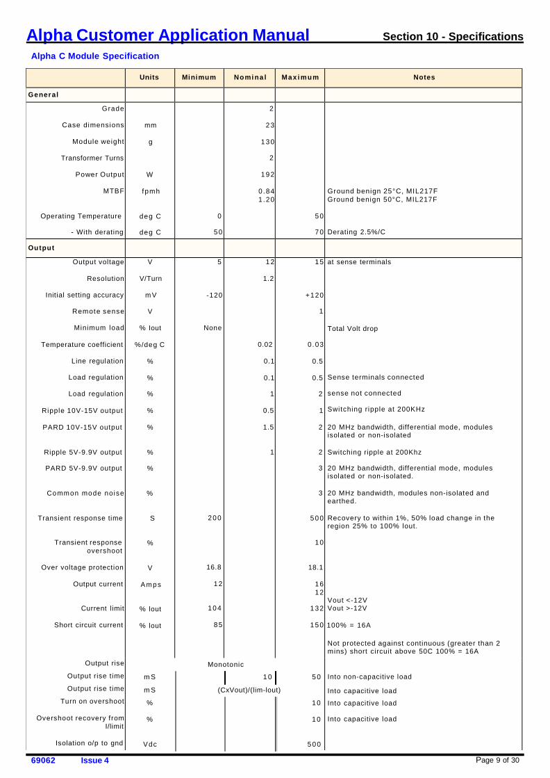
Alpha C Module Specification
Units
Minimum
Nomi na l
Max i mum
Notes
General Grade
Case dimensions
Module weight
Transformer Turns
Power Output
MTBF
Operating Temperature
- With derating
mm
g
W
f pmh
deg C
deg C
0
50
2
23
130
2
192
0.84 1 .20
50
70
Ground benign 25°C, MIL217F Ground benign 50°C, MIL217F
Derating 2.5%/C
Output
Output voltage
Resolution
Initial setting accuracy
Remote sense
Minimum load
Temperature coefficient
Line regulation
Load regulation
Load regulation
Ripple 10V-15V output
PARD 10V-15V output
Ripple 5V-9.9V output
PARD 5V-9.9V output
Common mode noise
Transient response time
Transient response overshoot
Over voltage protection
Output current
Current limit
Short circuit current
Output rise
Output rise time
Output rise time
Turn on overshoot
Overshoot recovery from I/limit
Isolation o/p to gnd
V
V/Turn
m V
V
% Iout
%/deg C
%
%
%
%
%
%
%
%
S
%
V
A mp s
% lout
% lout
5
-120
None
200
16.8
12
104
85
12
1.2
0.02
0.1
0.1
1
0.5
1.5
1
15
+120
1
0.03
0.5
0.5
2
1
2
2
3
3
500
10
18.1
16 12
132
150
at sense terminals Total Volt drop
Sense terminals connected sense not connected Switching r ipple at 200KHz
20 MHz bandwidth, differential mode, modules isolated or non-isolated
Switching ripple at 200Khz
20 MHz bandwidth, differential mode, modules isolated or non-isolated.
20 MHz bandwidth, modules non-isolated and earthed.
Recovery to within 1%, 50% load change in the region 25% to 100% lout.
Vout <-12V Vout >-12V
100% = 16A Not protected against continuous (greater than 2 mins) short circuit above 50C 100% = 16A
Into non-capacitive load Into capacitive load
Into capacitive load
Into capacitive load
Monotonic
m S 1 0 5 0
m S (CxVout)/(lim-lout)
% 10
% 10
Vdc 500
Page 10 of 30 69062 Issue 4
Alpha Customer Application Manual Section 10 - Specifications
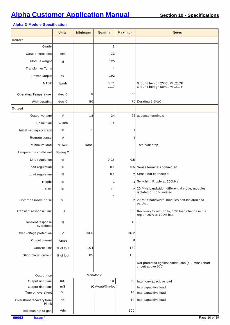
Alpha D Module Specification
Units
Minimum
Nominal
Maximum
Notes
General Grade
Case dimensions
Module weight
Transformer Turns
Power Output
MTBF
Operating Temperature
- With derating
mm
g
W
fpmh
deg C
deg C
0
50
2
23
125
4
192
0.82 1.17
50
70
Ground benign 25°C, MIL217F Ground benign 50°C, MIL217F
Derating 2.5%/C
Output
Output voltage
Resolution
Initial setting accuracy
Remote sense
Minimum load
Temperature coefficient
Line regulation
Load regulation
Load regulation
Ripple
PARD
Common mode noise
Transient response time
Transient response overshoot
Over voltage protection
Output current
Current limit
Short circuit current
Output rise
Output rise time
Output rise time
Turn on overshoot
Overshoot recovery from I/limit
Isolation o/p to gnd
V
V/Turn
%
V
% Iout
%/deg C
%
%
%
%
%
%
S
%
V
Amps
% of lout
% of lout
18
-1
None
33.4
104
85
24
1.4
0.02
0.1
0.1
1
0.5
1
28
1
1
0.03
0.5
0.5
2
1
2
2
500
10
36.2
8
132
160
at sense terminals Total Volt drop
Sense terminals connected
Sense not connected
Switching Ripple at 200kHz
20 MHz bandwidth, differential mode, modules isolated or non-isolated
20 MHz bandwidth, modules non-isolated and earthed.
Recovery to within 1%, 50% load change in the region 25% to 100% lout.
Not protected against continuous (> 2 mins) short circuit above 50C
Into non-capacitive load
Into capacitive load
Into capacitive load
Into capacitive load
Monotonic
mS 10 50
mS (CxVout)/(lim-lout)
% 10
% 10
Vdc 500
Page 11 of 30 69062 Issue 4
Alpha Customer Application Manual Section 10 - Specifications
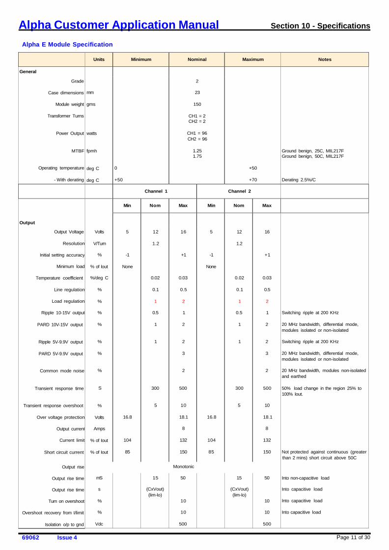
Alpha E Module Specification
Units
Minimum
Nominal
Maximum
Notes
General Grade
Case dimensions
Module weight
Transformer Turns
Power Output
MTBF
Operating temperature
- With derating
mm
gms
watts
fpmh
deg C deg C
0
+50
2
23
150
CH1 = 2 CH2 = 2
CH1 = 96 CH2 = 96
1.25 1.75
+50
+70
Ground benign, 25C, MIL217F Ground benign, 50C, MIL217F Derating 2.5%/C
Channel 1
Channel 2
Output
Min
Nom
Max
Min
Nom
Max
Output Voltage
Resolution
Initial setting accuracy
Minimum load
Temperature coefficient
Line regulation
Load regulation
Ripple 10-15V output
PARD 10V-15V output
Ripple 5V-9.9V output
PARD 5V-9.9V output
Common mode noise
Transient response time
Transient response overshoot
Over voltage protection
Output current
Current limit
Short circuit current
Output rise
Output rise time
Output rise time
Turn on overshoot
Overshoot recovery from I/limit
Isolation o/p to gnd
Volts
V/Turn
%
% of lout
%/deg C
%
%
%
%
%
%
%
S
%
Volts
Amps
% of Iout
% of Iout
5
-1
None
16.8
104
85
12
1.2
0.02
0.1
1
0.5
1
1
300
5
16
+1
0.03
0.5
2
1
2
2
3
2
500
10
18.1
8
132
150
5
-1
None
16.8
104
85
12
1.2
0.02
0.1
1
0.5
1
1
300
5
16
+1
0.03
0.5
2
1
2
2
3
2
500
10
18.1
8
132
150
Switching ripple at 200 KHz 20 MHz bandwidth, differential mode, modules isolated or non-isolated Switching ripple at 200 KHz 20 MHz bandwidth, differential mode, modules isolated or non-isolated 20 MHz bandwidth, modules non-isolated and earthed 50% load change in the region 25% to 100% lout. Not protected against continuous (greater than 2 mins) short circuit above 50C
Into non-capacitive load Into capacitive load
Into capacitive load
Into capacitive load
Monotonic
mS
s
%
%
Vdc
15
(CxVout) (lim-lo)
50
10
10
500
15
(CxVout) (lim-lo)
50
10
10
500

Page 12 of 30 69062 Issue 4
Alpha Customer Application Manual Section 10 - Specifications
Alpha EB Module Specification
Units
Minimum
Nominal
Maximum
Notes
General Grade
Case dimensions
Module weight
Transformer Turns
Power Output
MTBF
Operating temperature
- With derating
mm
gms
watts
fpmh
deg C deg C
0
+50
2
23
150
CH1 = 1 CH2 = 1
CH1 = 45 CH2 = 45
1.34 2.10
+50
+70
Ground benign, 25C, MIL217F Ground benign, 50C, MIL217F Derating 2.5%/C
Channel 1
Channel 2
Output
Min
Nom
Max
Min
Nom
Max
Output Voltage
Resolution
Initial setting accuracy
Minimum load
Temperature coefficient
Line regulation
Load regulation
Ripple
PARD
Common mode noise
Transient response time
Transient response overshoot
Over voltage protection
Output current
Current limit
Short circuit current
Output rise
Output rise time
Output rise time
Turn on overshoot
Overshoot recovery from I/limit
Isolation o/p to gnd
Volts
V/Turn
%
% of lout
%/deg C
%
%
%
%
%
S
%
Volts
Amps
% of Iout
% of Iout
4.5
-1
None
6.15
104
85
5.0
0.17
0.02
0.1
1
0.5
1
300
5
5.5
+1
0.03
0.5
2 1
2
2
500
10
7.0
9
132
150
4.5
-1
None
6.15
104
85
5.0
0.17
0.02
0.1
1 0.5
1
300
5
5.5
+1
0.03
0.5
2
1
2
2
500
10
7.0
9
132
150
Switching ripple at 200 KHz 20 MHz bandwidth, differential mode, modules isolated or non-isolated 20 MHz bandwidth, modules non-isolated and earthed 50% load change in the region 25% to 100% lout.
Not protected against continuous (greater than 2 mins) short circuit above 50C
Into non-capacitive load Into capacitive load
Into capacitive load
Into capacitive load
Monotonic
mS
s
%
%
Vdc
15
(CxVout) (lim-lo)
50
10
10
500
15
(CxVout) (lim-lo)
50
10
10
500

Page 13 of 30 69062 Issue 4
Alpha Customer Application Manual Section 10 - Specifications
Alpha EQ Module Specification
Units
Minimum
Nominal
Maximum
Notes
General Grade
Case dimensions
Module weight
Transformer Turns
Power Output
MTBF
Operating temperature
- With derating
mm
gms
watts
fpmh
deg C deg C
0
+50
2
23
150
CH1 = 1 CH2 = 1
CH1 = 45 CH2 = 45
1.25 1.75
+50
+70
Ground benign, 25C, MIL217F Ground benign, 50C, MIL217F Derating 2.5%/C
Channel 1
Channel 2
Output
Min
Nom
Max
Min
Nom
Max
Output Voltage
Resolution
Initial setting accuracy
Minimum load
Temperature coefficient
Line regulation
Load regulation
Ripple
PARD
Common mode noise
Transient response time
Transient response overshoot
Over voltage protection
Output current
Current limit
Short circuit current
Output rise
Output rise time
Output rise time
Turn on overshoot
Overshoot recovery from I/limit
Isolation o/p to gnd
Volts
V/Turn
%
% of lout
%/deg C
%
%
%
%
%
S
%
Volts
Amps
% of Iout
% of Iout
4.5
-1
None
6.15
104
85
5.0
0.17
0.02
0.1
1
0.5
1
300
5
5.5
+1
0.03
0.5
2
1
2
2
500
10
7.0
9
132
150
2.7
-1
None
4.26
104
85
3.3
0.3
0.02
0.1
1
0.5
1
300
5
3.9
+1
0.03
0.5
2
1
2
2
500
10
4.59
9
132
150
Switching ripple at 200 KHz 20 MHz bandwidth, differential mode, modules isolated or non-isolated 20 MHz bandwidth, modules non-isolated and earthed 50% load change in the region 25% to 100% lout.
Not protected against continuous (greater than 2 mins) short circuit above 50C
Into non-capacitive load Into capacitive load
Into capacitive load
Into capacitive load
Monotonic
mS
s
%
%
Vdc
15
(CxVout) (lim-lo)
50
10
10
500
15
(CxVout) (lim-lo)
50
10
10
500
Page 14 of 30 69062 Issue 4
Alpha Customer Application Manual Section 10 - Specifications
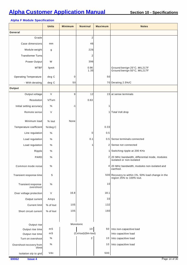
Alpha F Module Specification
Units
Minimum
Nominal
Maximum
Notes
General Grade
Case dimensions
Module weight
Transformer Turns
Power Output
MTBF
Operating Temperature
- With derating
mm
g
W
fpmh
deg C
deg C
0
50
2
46
226
2
396
0.96 1.35
50
70
Ground benign 25°C, MIL217F Ground benign 50°C, MIL217F
Derating 2.5%/C
Output
Output voltage
Resolution
Initial setting accuracy
Remote sense
Minimum load
Temperature coefficient
Line regulation
Load regulation
Load regulation
Ripple
PARD
Common mode noise
Transient response time
Transient response overshoot
Over voltage protection
Output current
Current limit
Short circuit current
Output rise
Output rise time
Output rise time
Turn on overshoot
Overshoot recovery from I/limit
Isolation o/p to gnd
V
V/Turn
%
V
% Iout
%/deg C
%
%
%
%
%
%
S
%
V
Amps
% of lout
% of lout
9
-1
None
16.8
105
105
12
0.63
0
0.1
1
15
1
1
0.03
0.5
0.5
2
1
2
4
500
10
18.1
33
132
160
at sense terminals Total Volt drop
Sense terminals connected
Sense not connected
Switching ripple at 200 KHz
20 MHz bandwidth, differential mode, modules isolated or non-isolated
20 MHz bandwidth, modules non-isolated and earthed.
Recovery to within 1%, 50% load change in the region 25% to 100% lout.
Into non-capacitive load
Into capacitive load Into capacitive load
Into capacitive load
Monotonic
mS 10 50
mS (CxVout)/(lim-lout)
% 2 10
% 10
Vdc 500
Page 15 of 30 69062 Issue 4
Alpha Customer Application Manual Section 10 - Specifications
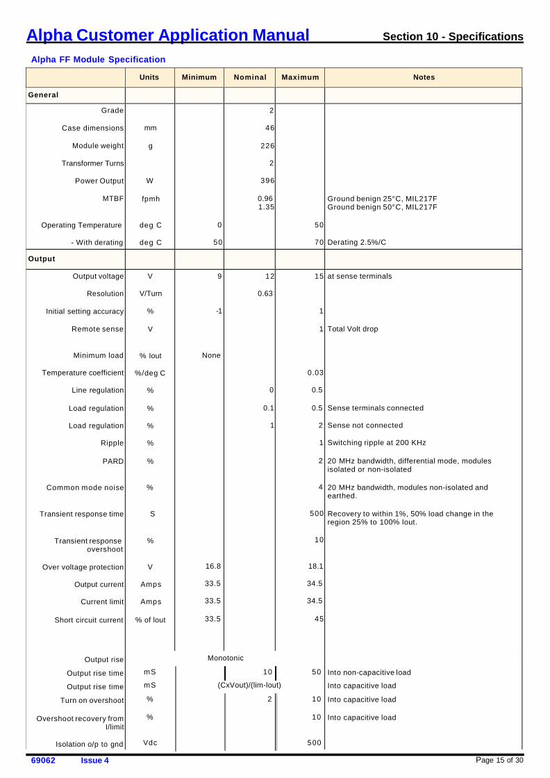
Alpha FF Module Specification
Units
Minimum
Nominal
Maximum
Notes
General Grade
Case dimensions
Module weight
Transformer Turns
Power Output
MTBF
Operating Temperature
- With derating
mm
g
W
fpmh
deg C
deg C
0
50
2
46
226
2
396
0.96 1.35
50
70
Ground benign 25°C, MIL217F Ground benign 50°C, MIL217F
Derating 2.5%/C
Output
Output voltage
Resolution
Initial setting accuracy
Remote sense
Minimum load
Temperature coefficient
Line regulation
Load regulation
Load regulation
Ripple
PARD
Common mode noise
Transient response time
Transient response overshoot
Over voltage protection
Output current
Current limit
Short circuit current
Output rise
Output rise time
Output rise time
Turn on overshoot
Overshoot recovery from I/limit
Isolation o/p to gnd
V
V/Turn
%
V
% Iout
%/deg C
%
%
%
%
%
%
S
%
V
Amps
Amps
% of lout
9
-1
None
16.8
33.5
33.5
33.5
12
0.63
0
0.1
1
15
1
1
0.03
0.5
0.5
2
1
2
4
500
10
18.1
34.5
34.5
45
at sense terminals Total Volt drop
Sense terminals connected
Sense not connected
Switching ripple at 200 KHz
20 MHz bandwidth, differential mode, modules isolated or non-isolated
20 MHz bandwidth, modules non-isolated and earthed.
Recovery to within 1%, 50% load change in the region 25% to 100% lout.
Into non-capacitive load
Into capacitive load Into capacitive load
Into capacitive load
Monotonic
mS 10 50
mS (CxVout)/(lim-lout)
% 2 10
% 10
Vdc 500
Page 16 of 30 69062 Issue 4
Alpha Customer Application Manual Section 10 - Specifications
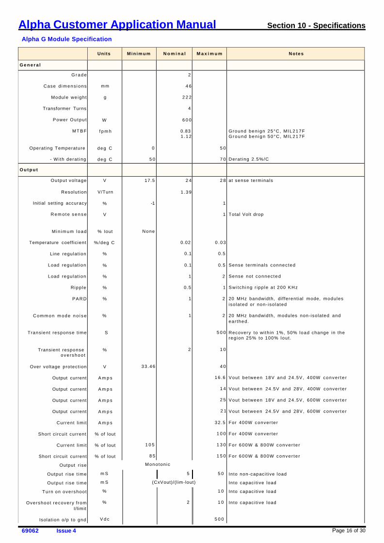
Alpha G Module Specification
Units
Min im um
N o m i n a l
M a x i m u m
N otes
G e n e r a l G r a d e
Case d i m ens i ons
Module weight
Transformer Turns
Power Ou tpu t
MT B F
Operating Temperature
- W i th derat ing
mm
g
W
f p m h
deg C
deg C
0
5 0
2
4 6
2 2 2
4
6 0 0
0.83 1 . 1 2
5 0
7 0
Ground ben ign 25°C, MIL217F Ground ben i gn 50°C , MIL 217F
Derat ing 2.5%/C
O u t p u t
Output vol tage
Resolut ion
Init ial setting accuracy
R em ot e se n s e
Mi n i m um l oad
Temperature coefficient
Line regulat ion
Load regulat ion
Load regulat ion
Ripp le
PAR D
C om m on m ode n o i s e
Transient response t ime
Transient response ove rshoo t
Over voltage protect ion
Output current
Output current
Output current
Output current
Current l imi t
Short ci rcui t current
Current l imi t
Short circuit current
Output r ise
Output r ise t ime
Output r i se t ime
Turn on overshoot
Overshoot recovery f rom I/limit
Isolation o/p to gnd
V
V/Turn
%
V
% Iout
%/deg C
%
%
%
%
%
%
S
%
V
A m p s
A m p s
A m p s
A m p s
A m p s
% of lout
% of lout
% of lout
17.5
-1
None
33 .4 6
1 0 5
8 5
2 4
1 . 3 9
0.02
0.1
0.1
1
0.5
1
1
2
2 8
1
1
0 . 0 3
0.5
0.5
2
1
2
2
5 0 0
1 0
4 0
16 .6
1 4
2 5
2 1
32 .5
1 0 0
1 3 0
1 5 0
at sense terminals Total Volt drop
Sense terminals connec ted
Sense not connec ted
S wi tch i ng r ipp le a t 200 KH z
20 MHz bandwidth, di f ferential mode, modules isolated or non- isolated
20 MHz bandwidth, modules non-isolated and ear thed.
Recovery to wi thin 1%, 50% load change in the reg ion 25% to 100% lou t .
Vout between 18V and 24.5V, 400W conver te r
Vout between 24.5V and 28V, 400W conve r ter
Vout between 18V and 24.5V, 600W conver te r
Vout between 24.5V and 28V, 600W conver ter
For 400W conver ter
For 400W conver ter For 600W & 800W conver te r
For 600W & 800W conver te r
Into non-capaci t ive load
Into capaci t ive load
Into capaci t ive load
Into capaci t ive load
Monoton ic
m S 5 5 0
m S (CxVout)/(l im-lout)
% 1 0
% 2 1 0
V d c 5 0 0
Page 17 of 30 69062 Issue 4
Alpha Customer Application Manual Section 10 - Specifications
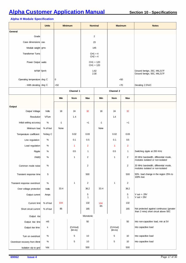
Alpha H Module Specification
Units
Minimum
Nominal
Maximum
Notes
General Grade
Case dimensions
Module weight
Transformer Turns
Power Output
MTBF
Operating temperature
- With derating
mm
gms
watts
fpmh
deg C deg C
0
+50
2
23
145
CH1 = 4 CH2 = 4
CH1 = 120 CH1 = 120
1.62 2.30
+50
+70
Ground benign, 25C, MIL217F Ground benign, 50C, MIL217F Derating 2.5%/C
Channel 1
Channel 2
Output
Min
Nom
Max
Min
Nom
Max
Output Voltage
Resolution
Initial setting accuracy
Minimum load
Temperature coefficient
Line regulation
Load regulation
Ripple
PARD
Common mode noise
Transient response time
Transient response overshoot
Over voltage protection
Output current
Current limit
Short circuit current
Output rise
Output rise time
Output rise time
Turn on overshoot
Overshoot recovery from I/limit
Isolation o/p to gnd
Volts
V/Turn
%
% of lout
%/deg C
%
%
%
%
%
S
%
Volts
Amps
% of Iout
% of Iout
18
-1
None
33.4
104
85
24
1.4
0.02
0.1
1
0.5
1
1
32
+1
0.03
0.5
2
1
2
2
500
2
36.2
5 1
132
165
18
-1
None
33.4
104 85
24
1.4
0.02
0.1
1
0.5
1
1
32
+1
0.03
0.5
2
1
2
2
500
2
36.2
5 1
132
165
Switching ripple at 200 KHz 20 MHz bandwidth, differential mode, modules isolated or non-isolated 20 MHz bandwidth, differential mode, modules isolated or non-isolated 50% load change in the region 25% to 100% lout.
V out <- 29V V out > 29V Not protected against continuous (greater than 2 mins) short circuit above 50C
Into non-capacitive load, min at 5V
Into capacitive load
Into capacitive load Into capacitive load
Monotonic
mS
s
%
%
Vdc
(CxVout) (lim-lo)
5
5
50
10
10
500
(CxVout) (lim-lo)
5
5
50
10
10
500
Page 18 of 30 69062 Issue 4
Alpha Customer Application Manual Section 10 - Specifications
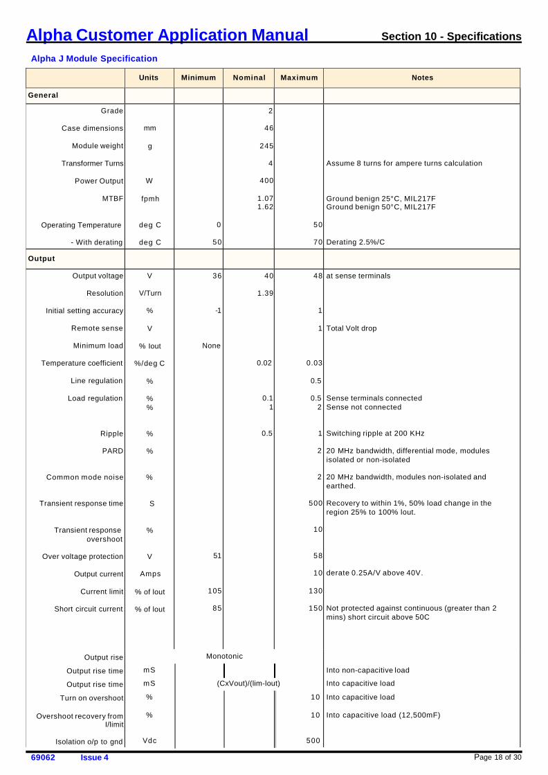
Alpha J Module Specification
Units
Minimum
Nominal
Maximum
Notes
General Grade
Case dimensions
Module weight
Transformer Turns
Power Output
MTBF
Operating Temperature
- With derating
mm
g
W
fpmh
deg C
deg C
0
50
2
46
245
4
400
1.07 1.62
50
70
Assume 8 turns for ampere turns calculation
Ground benign 25°C, MIL217F Ground benign 50°C, MIL217F
Derating 2.5%/C
Output
Output voltage
Resolution
Initial setting accuracy
Remote sense
Minimum load
Temperature coefficient
Line regulation
Load regulation
Ripple
PARD
Common mode noise
Transient response time
Transient response overshoot
Over voltage protection
Output current
Current limit
Short circuit current
Output rise
Output rise time
Output rise time
Turn on overshoot
Overshoot recovery from I/limit
Isolation o/p to gnd
V
V/Turn
%
V
% Iout
%/deg C
%
% %
%
%
%
S
%
V
Amps
% of lout
% of lout
36
-1
None
51
105
85
40
1.39
0.02
0.1 1
0.5
48
1
1
0.03
0.5
0.5 2
1
2
2
500
10
58
10
130
150
at sense terminals Total Volt drop
Sense terminals connected Sense not connected
Switching ripple at 200 KHz
20 MHz bandwidth, differential mode, modules isolated or non-isolated
20 MHz bandwidth, modules non-isolated and earthed.
Recovery to within 1%, 50% load change in the region 25% to 100% lout.
derate 0.25A/V above 40V.
Not protected against continuous (greater than 2 mins) short circuit above 50C
Into non-capacitive load
Into capacitive load Into capacitive load
Into capacitive load (12,500mF)
Monotonic
mS
mS (CxVout)/(lim-lout)
% 10
% 10
Vdc 500

Page 19 of 30 69062 Issue 4
Alpha Customer Application Manual Section 10 - Specifications
Alpha K Module Specification
Units
Minimum
Nominal
Maximum
Notes
General Grade
Case dimensions
Module weight
Transformer Turns
Power Output
MTBF
Operating Temperature
- With derating
mm
g
W
fpmh
deg C
deg C
0
50
2
46
150
4
360
0.84 1.22
50
70
Ground benign 25°C, MIL217F Ground benign 50°C, MIL217F
Derating 2.5%/C
Output
Output voltage
Resolution
Initial setting accuracy
Remote sense
Minimum load
Temperature coefficient
Line regulation
Load regulation
Load regulation
Ripple
PARD
Common mode noise
Transient response time
Transient response overshoot
Over voltage protection
Output current
Current limit
Short circuit current
Output rise
Output rise time
Output rise time
Turn on overshoot
Overshoot recovery from I/limit
Isolation o/p to gnd
V
V/Turn
%
V
% Iout
%/deg C
%
%
%
%
%
%
S
%
V
Amps
% of lout
% of lout
18
-1
None
32.8
104
85
24
1.39
0.02
0.1
0.1
1
0.5
1
28
1
1
0.03
0.5
0.5
2
1
2
2
500
10
35
15
132
160
at sense terminals Total Volt drop
Sense terminals connected
Sense not connected
Switching Ripple at 200kHz
20 MHz bandwidth, differential mode, modules isolated or non-isolated
20 MHz bandwidth, modules non-isolated and earthed.
Recovery to within 1%, 50% load change in the region 25% to 100% lout.
Not protected against continuous (> 2 mins) short circuit above 50C
Into non-capacitive load
Into capacitive load Into capacitive load
Into capacitive load
Monotonic
mS 10 50
mS (CxVout)/(lim-lout)
% 10
% 10
Vdc 500
Page 20 of 30 69062 Issue 4
Alpha Customer Application Manual Section 10 - Specifications
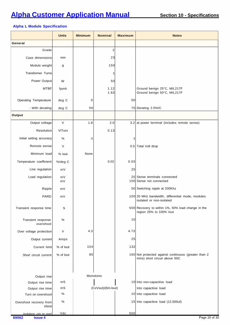
Alpha L Module Specification
Units
Minimum
Nominal
Maximum
Notes
General
Grade
Case dimensions
Module weight
Transformer Turns
Power Output
MTBF
Operating Temperature
- With derating
mm
g
W
fpmh
deg C
deg C
0
50
2
23
150
1
50
1.12 1.63
50
70
Ground benign 25°C, MIL217F Ground benign 50°C, MIL217F
Derating 2.5%/C
Output
Output voltage
Resolution
Initial setting accuracy
Remote sense
Minimum load
Temperature coefficient
Line regulation
Load regulation
Ripple
PARD
Transient response time
Transient response overshoot
Over voltage protection
Output current
Current limit
Short circuit current
Output rise
Output rise time
Output rise time
Turn on overshoot
Overshoot recovery from I/limit
Isolation o/p to gnd
V
V/Turn
%
V
% Iout
%/deg C
mV
mV mV
mV
mV
S
%
V
Amps
% of lout
% of lout
1.8
-1
None
4.3
104
85
2.0
0.13
0.02
3.2
1
0.5
0.03
25
25 100
50
100
500
10
4.73
25
132
160
at power terminal (includes remote sense) Total Volt drop
Sense terminals connected Sense not connected
Switching ripple at 200Khz
20 MHz bandwidth, differential mode, modules isolated or non-isolated
Recovery to within 1%, 50% load change in the region 25% to 100% Iout
Not protected against continuous (greater than 2 mins) short circuit above 50C
Into non-capacitive load
Into capacitive load
Into capacitive load
Into capacitive load (12,500uf)
Monotonic
mS
mS
%
%
Vdc
10
(CxVout)/(lim-lout)
10
15
500
Alpha Customer Application Manual Section 10 - Specifications
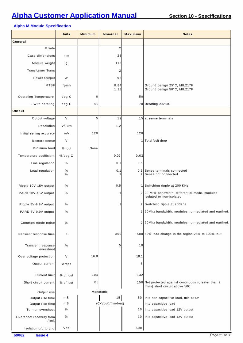
Alpha M Module Specification
Page 21 of 30 69062 Issue 4
Units
Minimum
Nominal
Maximum
Notes
General Grade
Case dimensions
Module weight
Transformer Turns
Power Output
MTBF
Operating Temperature
- With derating
mm
g
W
fpmh
deg C
deg C
0
50
2
23
115
2
96
0.84 1 .18
50
70
Ground benign 25°C, MIL217F Ground benign 50°C, MIL217F
Derating 2.5%/C
Output
Output voltage
Resolution
Initial setting accuracy
Remote sense
Minimum load
Temperature coefficient
Line regulation
Load regulation
Ripple 10V-15V output
PARD 10V-15V output
Ripple 5V-9.9V output
PARD 5V-9.9V output
Common mode noise
Transient response time
Transient response overshoot
Over voltage protection
Output current
Current limit
Short circuit current
Output rise
Output rise time
Output rise time
Turn on overshoot
Overshoot recovery from I/limit
Isolation o/p to gnd
V
V/Turn
m V
V
% Iout
%/deg C
%
% %
%
%
%
%
%
S
%
V
Amps
% of lout
% of lout
5
120
None
16.8
104
85
12
1.2
0.02
0.1
0.1 1
0.5
1
1
350
5
15
120
1
0.03
0.5
0.5 2
1
2
2
3
2
500
10
18.1
8
132
150
at sense terminals Total Volt drop
Sense terminals connected Sense not connected
Switching ripple at 200 KHz
20 MHz bandwidth, differential mode, modules isolated or non-isolated
Switching ripple at 200Khz
20Mhz bandwidth, modules non-isolated and earthed.
20Mhz bandwidth, modules non-isolated and earthed.
50% load change in the region 25% to 100% lout
Not protected against continuous (greater than 2 mins) short circuit above 50C
Into non-capacitive load, min at 5V
Into capacitive load
Into capacitive load 12V output Into capacitive load 12V output
Monotonic
m S 15 50
m S (CxVout)/(lim-lout)
% 10
% 10
Vdc 500
Page 22 of 30 69062 Issue 4
Alpha Customer Application Manual Section 10 - Specifications
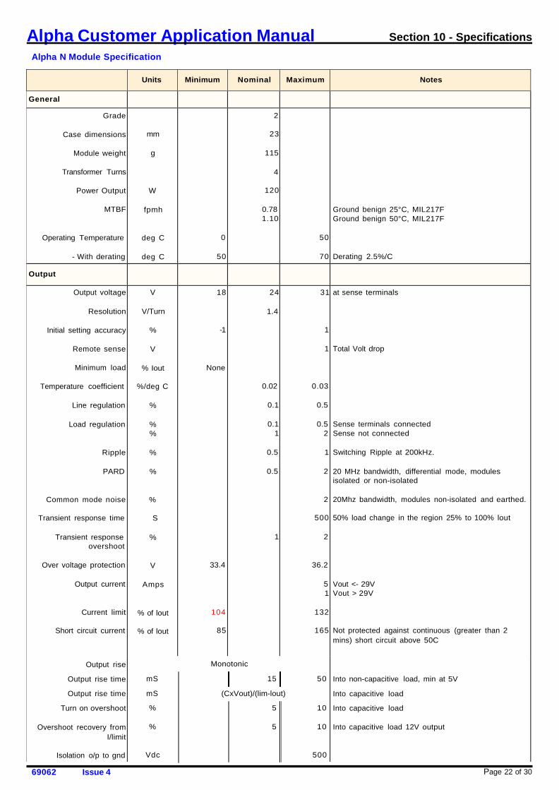
Alpha N Module Specification
Units
Minimum
Nominal
Maximum
Notes
General
Grade
Case dimensions
Module weight
Transformer Turns
Power Output
MTBF
Operating Temperature
- With derating
mm
g
W
fpmh
deg C
deg C
0
50
2
23
115
4
120
0.78 1.10
50
70
Ground benign 25°C, MIL217F Ground benign 50°C, MIL217F
Derating 2.5%/C
Output
Output voltage
Resolution
Initial setting accuracy
Remote sense
Minimum load
Temperature coefficient
Line regulation
Load regulation
Ripple
PARD
Common mode noise
Transient response time
Transient response overshoot
Over voltage protection
Output current
Current limit
Short circuit current
Output rise
Output rise time
Output rise time
Turn on overshoot
Overshoot recovery from I/limit
Isolation o/p to gnd
V
V/Turn
%
V
% Iout
%/deg C
%
% %
%
%
%
S
%
V
Amps
% of lout
% of lout
18
-1
None
33.4
104
85
24
1.4
0.02
0.1
0.1 1
0.5
0.5
1
31
1
1
0.03
0.5
0.5 2
1
2
2
500
2
36.2
5 1
132
165
at sense terminals Total Volt drop
Sense terminals connected Sense not connected
Switching Ripple at 200kHz.
20 MHz bandwidth, differential mode, modules isolated or non-isolated
20Mhz bandwidth, modules non-isolated and earthed.
50% load change in the region 25% to 100% lout
Vout <- 29V Vout > 29V
Not protected against continuous (greater than 2 mins) short circuit above 50C
Into non-capacitive load, min at 5V
Into capacitive load
Into capacitive load Into capacitive load 12V output
Monotonic
mS 15 50
mS (CxVout)/(lim-lout)
% 5 10
% 5 10
Vdc 500
Page 23 of 30 69062 Issue 4
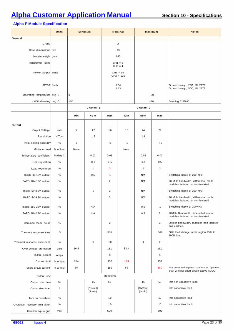
Alpha Customer Application Manual Section 10 - Specifications
Alpha P Module Specification
Units
Minimum
Nominal
Maximum
Notes
General Grade
Case dimensions
Module weight
Transformer Turns
Power Output
MTBF
Operating temperature
- With derating
mm
gms
watts
fpmh
deg C deg C
0
+50
2
23
145
CH1 = 2 CH2 = 4
CH1 = 96 CH2 = 120
1.64 2.33
+50
+70
Ground benign, 25C, MIL217F Ground benign, 50C, MIL217F Derating 2.5%/C
Channel 1
Channel 2
Output
Min
Nom
Max
Min
Nom
Max
Output Voltage
Resolution
Initial setting accuracy
Minimum load
Temperature coefficient
Line regulation
Load regulation
Ripple 10-15V output
PARD 10V-15V output
Ripple 5V-9.9V output
PARD 5V-9.9V output
Ripple 18V-29V output
PARD 18V-29V output
Common mode noise
Transient response time
Transient response overshoot
Over voltage protection
Output current
Current limit
Short circuit current
Output rise
Output rise time
Output rise time
Turn on overshoot
Overshoot recovery from I/limit
Isolation o/p to gnd
Volts
V/Turn
%
% of lout
%/deg C
%
%
%
%
%
%
%
%
%
S
%
Volts
Amps
% of Iout
% of Iout
5
-1
None
16.8
104
85
12
1.2
0.02
0.1
1
0.5
1
N/A
N/A
5
16
+1
0.03
0.5
2
1
2
2
3
2
500
10
18.1
8
132
150
18
-1
None
33.4
104
85
24
1.4
0.02
0.1
1
N/A
N/A
N/A
N/A
0.5
0.5
1
29
+1
0.03
0.5
2
1
2
2
500
2
36.2
5
132
150
Switching ripple at 200 KHz 20 MHz bandwidth, differential mode, modules isolated or non-isolated Switching ripple at 200 KHz 20 MHz bandwidth, differential mode, modules isolated or non-isolated Switching ripple at 200KHz 20MHz Bandwidth, differential mode, modules isolated or non-isolated 20MHz bandwidth, modules non-isolated and earthed. 50% load change in the region 25% to 100% lout. Not protected against continuous (greater than 2 mins) short circuit above 50CC
Into non-capacitive load Into capacitive load Into capacitive load Into capacitive load
Monotonic
mS
s
%
%
Vdc
15
(CxVout) (lim-lo)
50
10
10
500
15
(CxVout) (lim-lo)
50
10
10
500
Page 24 of 30 69062 Issue 4
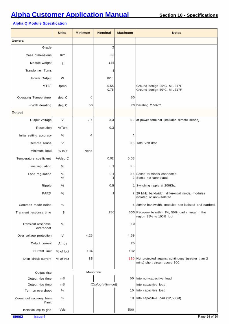
Alpha Customer Application Manual Section 10 - Specifications
Alpha Q Module Specification
Units
Minimum
Nominal
Maximum
Notes
General
Grade
Case dimensions
Module weight
Transformer Turns
Power Output
MTBF
Operating Temperature
- With derating
mm
g
W
fpmh
deg C
deg C
0
50
2
23
145
1
82.5
0.55 0.78
50
70
Ground benign 25°C, MIL217F Ground benign 50°C, MIL217F
Derating 2.5%/C
Output
Output voltage
Resolution
Initial setting accuracy
Remote sense
Minimum load
Temperature coefficient
Line regulation
Load regulation
Ripple
PARD
Common mode noise
Transient response time
Transient response overshoot
Over voltage protection
Output current
Current limit
Short circuit current
Output rise
Output rise time
Output rise time
Turn on overshoot
Overshoot recovery from I/limit
Isolation o/p to gnd
V
V/Turn
%
V
% Iout
%/deg C
%
% %
%
%
%
S
%
V
Amps
% of lout
% of lout
2.7
-1
None
4.26
104
85
3.3
0.3
0.02
0.1
0.1 1
0.5
1
150
3.9
1
0.5
0.03
0.5
0.5 2
1
2
4
500
10
4.59
25
132
150
at power terminal (includes remote sense) Total Volt drop
Sense terminals connected Sense not connected
Switching ripple at 200Khz
20 MHz bandwidth, differential mode, modules isolated or non-isolated
20Mhz bandwidth, modules non-isolated and earthed.
Recovery to within 1%, 50% load change in the region 25% to 100% Iout
Not protected against continuous (greater than 2 mins) short circuit above 50C
Into non-capacitive load
Into capacitive load
Into capacitive load
Into capacitive load (12,500uf)
Monotonic
mS 50
mS (CxVout)/(lim-lout)
% 10
% 10
Vdc 500
Page 25 of 30 69062 Issue 4
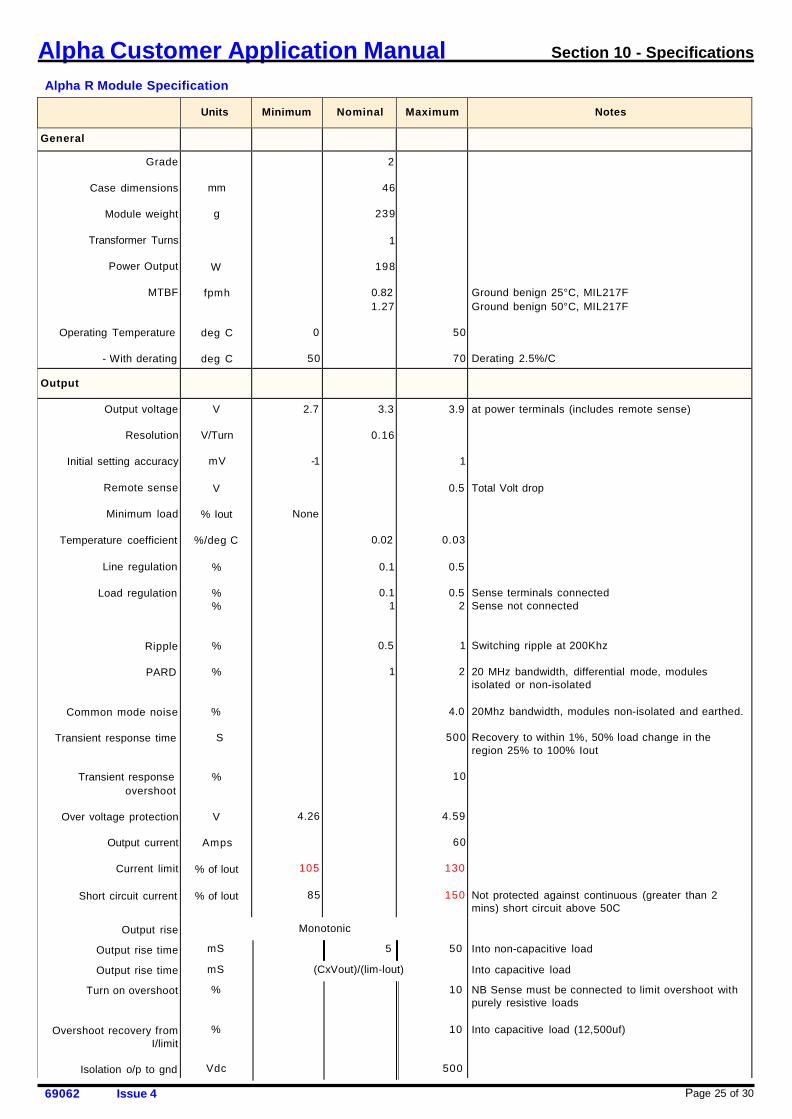
Alpha Customer Application Manual Section 10 - Specifications
Alpha R Module Specification
Units
Minimum
Nominal
Maximum
Notes
General
Grade
Case dimensions
Module weight
Transformer Turns
Power Output
MTBF
Operating Temperature
- With derating
mm
g
W
fpmh
deg C
deg C
0
50
2
46
239
1
198
0.82 1.27
50
70
Ground benign 25°C, MIL217F Ground benign 50°C, MIL217F
Derating 2.5%/C
Output
Output voltage
Resolution
Initial setting accuracy
Remote sense
Minimum load
Temperature coefficient
Line regulation
Load regulation
Ripple
PARD
Common mode noise
Transient response time
Transient response overshoot
Over voltage protection
Output current
Current limit
Short circuit current
Output rise
Output rise time
Output rise time
Turn on overshoot
Overshoot recovery from
I/limit
Isolation o/p to gnd
V
V/Turn
mV
V
% Iout
%/deg C
%
% %
%
%
%
S
%
V
Amps
% of lout
% of lout
2.7
-1
None
4.26
105
85
3.3
0.16
0.02
0.1
0.1 1
0.5
1
3.9
1
0.5
0.03
0.5
0.5 2
1
2
4.0
500
10
4.59
60
130
150
at power terminals (includes remote sense) Total Volt drop
Sense terminals connected Sense not connected
Switching ripple at 200Khz
20 MHz bandwidth, differential mode, modules isolated or non-isolated
20Mhz bandwidth, modules non-isolated and earthed.
Recovery to within 1%, 50% load change in the region 25% to 100% Iout
Not protected against continuous (greater than 2 mins) short circuit above 50C
Into non-capacitive load
Into capacitive load
NB Sense must be connected to limit overshoot with purely resistive loads
Into capacitive load (12,500uf)
Monotonic
mS 5 50
mS (CxVout)/(lim-lout)
% 10
% 10
Vdc 500
Page 26 of 30 69062 Issue 4
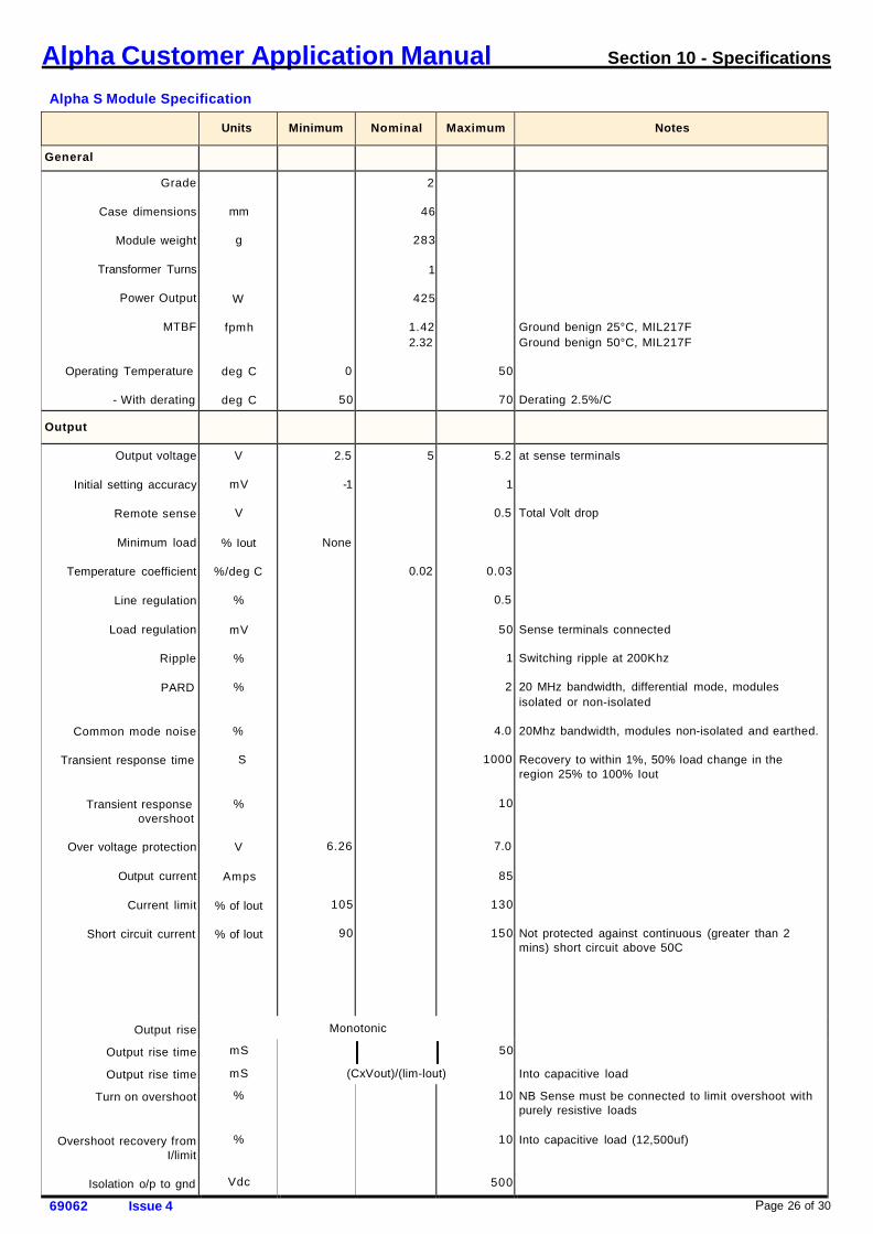
Alpha Customer Application Manual Section 10 - Specifications
Alpha S Module Specification
Units
Minimum
Nominal
Maximum
Notes
General
Grade
Case dimensions
Module weight
Transformer Turns
Power Output
MTBF
Operating Temperature
- With derating
mm
g
W
fpmh
deg C
deg C
0
50
2
46
283
1
425
1.42 2.32
50
70
Ground benign 25°C, MIL217F Ground benign 50°C, MIL217F
Derating 2.5%/C
Output
Output voltage
Initial setting accuracy
Remote sense
Minimum load
Temperature coefficient
Line regulation
Load regulation
Ripple
PARD
Common mode noise
Transient response time
Transient response overshoot
Over voltage protection
Output current
Current limit
Short circuit current
Output rise
Output rise time
Output rise time
Turn on overshoot
Overshoot recovery from
I/limit
Isolation o/p to gnd
V
mV
V
% Iout
%/deg C
%
mV
%
%
%
S
%
V
Amps
% of lout
% of lout
2.5
-1
None
6.26
105
90
5
0.02
5.2
1
0.5
0.03
0.5
50
1
2
4.0
1000
10
7.0
85
130
150
at sense terminals Total Volt drop
Sense terminals connected
Switching ripple at 200Khz
20 MHz bandwidth, differential mode, modules isolated or non-isolated
20Mhz bandwidth, modules non-isolated and earthed.
Recovery to within 1%, 50% load change in the region 25% to 100% Iout
Not protected against continuous (greater than 2 mins) short circuit above 50C
Into capacitive load
NB Sense must be connected to limit overshoot with purely resistive loads
Into capacitive load (12,500uf)
Monotonic
mS
mS
%
%
Vdc
50
(CxVout)/(lim-lout)
10
10
500
Page 27 of 30 69062 Issue 4
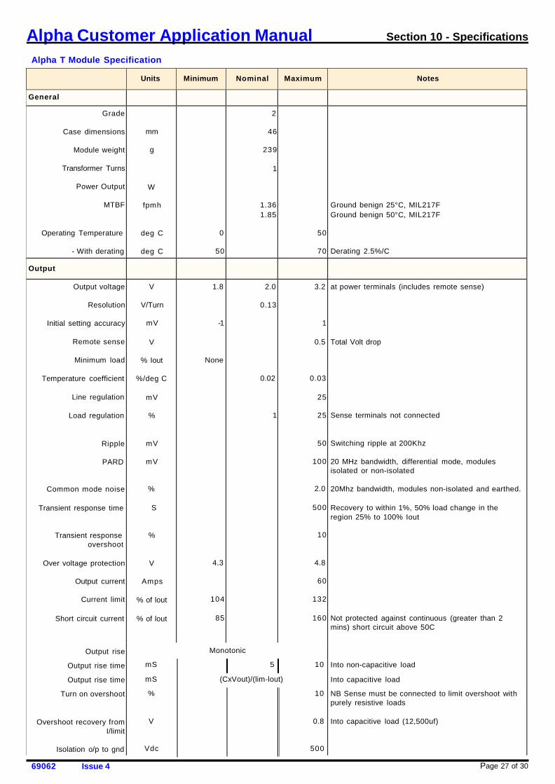
Alpha Customer Application Manual Section 10 - Specifications
Alpha T Module Specification
Units
Minimum
Nominal
Maximum
Notes
General
Grade
Case dimensions
Module weight
Transformer Turns
Power Output
MTBF
Operating Temperature
- With derating
mm
g
W
fpmh
deg C
deg C
0
50
2
46
239
1
1.36 1.85
50
70
Ground benign 25°C, MIL217F Ground benign 50°C, MIL217F
Derating 2.5%/C
Output
Output voltage
Resolution
Initial setting accuracy
Remote sense
Minimum load
Temperature coefficient
Line regulation
Load regulation
Ripple
PARD
Common mode noise
Transient response time
Transient response overshoot
Over voltage protection
Output current
Current limit
Short circuit current
Output rise
Output rise time
Output rise time
Turn on overshoot
Overshoot recovery from
I/limit
Isolation o/p to gnd
V
V/Turn
mV
V
% Iout
%/deg C
mV
%
mV
mV
%
S
%
V
Amps
% of lout
% of lout
1.8
-1
None
4.3
104
85
2.0
0.13
0.02
1
3.2
1
0.5
0.03
25
25
50
100
2.0
500
10
4.8
60
132
160
at power terminals (includes remote sense) Total Volt drop
Sense terminals not connected
Switching ripple at 200Khz
20 MHz bandwidth, differential mode, modules isolated or non-isolated
20Mhz bandwidth, modules non-isolated and earthed.
Recovery to within 1%, 50% load change in the region 25% to 100% Iout
Not protected against continuous (greater than 2 mins) short circuit above 50C
Into non-capacitive load
Into capacitive load
NB Sense must be connected to limit overshoot with purely resistive loads
Into capacitive load (12,500uf)
Monotonic
mS 5 10
mS (CxVout)/(lim-lout)
% 10
V 0.8
Vdc 500

Page 28 of 30 69062 Issue 4
Alpha Customer Application Manual Section 10 - Specifications
Alpha U Module Specification
Units
Minimum
Nominal
Maximum
Notes
General Grade
Case dimensions
Module weight
Transformer Turns
Power Output
MTBF
Operating Temperature
- With derating
mm
g
W
fpmh
deg C
deg C
0
50
2
23
133
3
256
1.06 1.61
50
70
Ground benign 25°C, MIL217F Ground benign 50°C, MIL217F
Derating 2.5%/C
Output
Output voltage
Resolution
Initial setting accuracy
Remote sense
Minimum load
Temperature coefficient
Line regulation
Load regulation
Load regulation
Ripple
PARD
Common mode noise
Transient response time
Transient response overshoot
Over voltage protection
Output current
Current limit
Short circuit current
Output rise
Output rise time
Output rise time
Turn on overshoot
Overshoot recovery from I/limit
Isolation o/p to gnd
V
V/Turn
%
V
% Iout
%/deg C
%
%
%
%
%
%
S
%
V
Amps
% of lout
% of lout
10
-1
None
21.9
104
85
16
1.0
0.02
0.1
0.1
1
0.5
1
20
1
1
0.03
0.5
0.5
2
1
2
2
500
10
24.3
16
132
160
at sense terminals
Total Volt drop
Sense terminals connected
Sense not connected
Switching Ripple at 200kHz
20 MHz bandwidth, differential mode, modules isolated or non-isolated
20 MHz bandwidth, modules non-isolated and earthed.
Recovery to within 1%, 50% load change in the region 25% to 100% lout.
Not protected against continuous (> 2 mins) short circuit above 50C
Into non-capacitive load
Into capacitive load Into capacitive load
Into capacitive load
Monotonic
mS 10 50
mS (CxVout)/(lim-lout)
% 10
% 10
Vdc 500
Page 29 of 30 69062 Issue 4
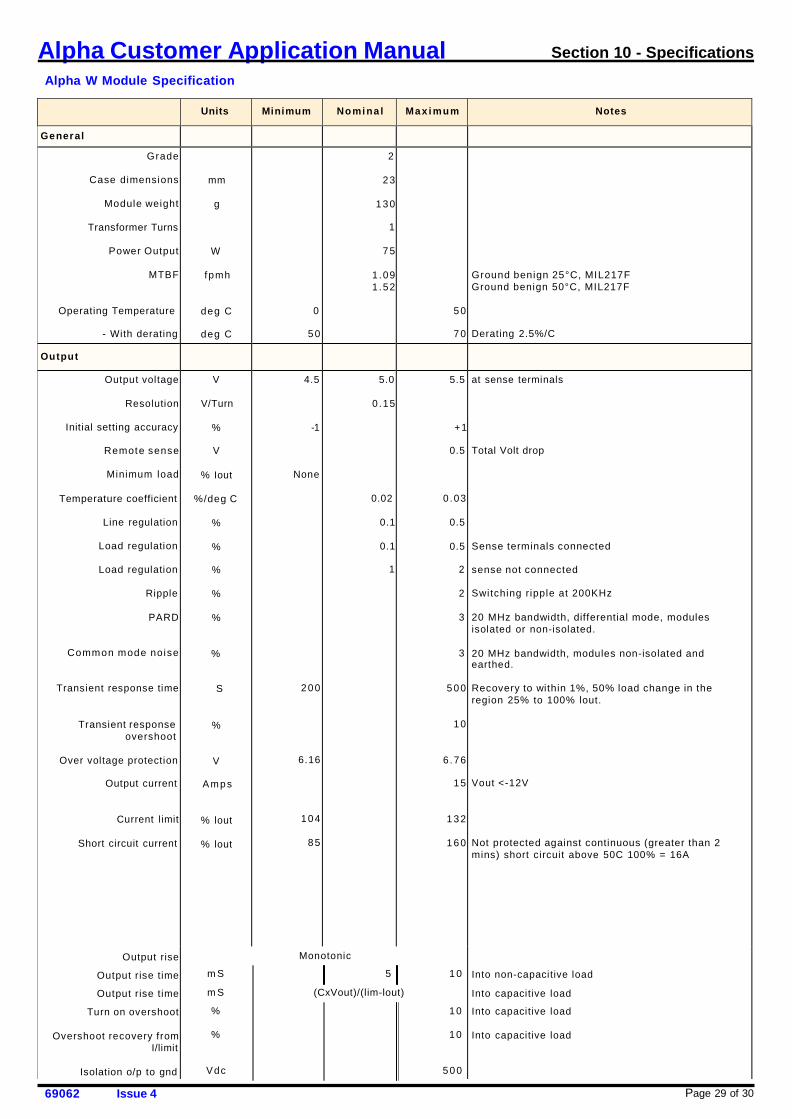
Alpha Customer Application Manual Section 10 - Specifications
Alpha W Module Specification
Units
Minimum
Nomi na l
Max i mum
Notes
General Grade
Case dimensions
Module weight
Transformer Turns
Power Output
MTBF
Operating Temperature
- With derating
mm
g
W
f pmh
deg C
deg C
0
50
2
23
130
1
75
1.09 1 .52
50
70
Ground benign 25°C, MIL217F Ground benign 50°C, MIL217F
Derating 2.5%/C
Output
Output voltage
Resolution
Initial setting accuracy
Remote sense
Minimum load
Temperature coefficient
Line regulation
Load regulation
Load regulation
Ripple
PARD
Common mode noise
Transient response time
Transient response overshoot
Over voltage protection
Output current
Current limit
Short circuit current
Output rise
Output rise time
Output rise time
Turn on overshoot
Overshoot recovery from I/limit
Isolation o/p to gnd
V
V/Turn
%
V
% Iout
%/deg C
%
%
%
%
%
%
S
%
V
A mp s
% lout
% lout
4.5
-1
None
200
6.16
104
85
5.0
0.15
0.02
0.1
0.1
1
5.5
+1
0.5
0.03
0.5
0.5
2
2
3
3
500
10
6.76
15
132
160
at sense terminals Total Volt drop
Sense terminals connected
sense not connected
Switching r ipple at 200KHz
20 MHz bandwidth, differential mode, modules isolated or non-isolated.
20 MHz bandwidth, modules non-isolated and earthed.
Recovery to within 1%, 50% load change in the region 25% to 100% lout.
Vout <-12V
Not protected against continuous (greater than 2 mins) short circuit above 50C 100% = 16A
Into non-capacitive load
Into capacitive load
Into capacitive load Into capacitive load
Monotonic
m S 5 1 0
m S (CxVout)/(lim-lout)
% 10
% 10
Vdc 500
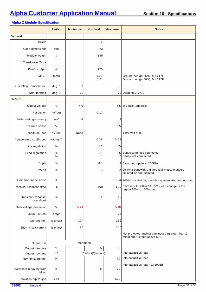
Page 30 of 30 69062 Issue 4
Alpha Customer Application Manual Section 10 - Specifications
Alpha Z Module Specification
Units
Minimum
Nominal
Maximum
Notes
General
Grade
Case dimensions
Module weight
Transformer Turns
Power Output
MTBF
Operating Temperature
- With derating
mm
g
W
fpmh
deg C
deg C
0
50
2
23
145
1
125
0.90 1.31
50
70
Ground benign 25°C, MIL217F Ground benign 50°C, MIL217F
Derating 2.5%/C
Output
Output voltage
Resolution
Initial setting accuracy
Remote sense
Minimum load
Temperature coefficient
Line regulation
Load regulation
Ripple
PARD
Common mode noise
Transient response time
Transient response overshoot
Over voltage protection
Output current
Current limit
Short circuit current
Output rise
Output rise time
Output rise time
Turn on overshoot
Overshoot recovery from
I/limit
Isolation o/p to gnd
V
V/Turn
mV
V
% Iout
%/deg C
%
% %
%
%
%
S
%
V
Amps
% of lout
% of lout
4.5
-1
None
5.73
104
85
0.17
0.02
0.1
0.1 1
0.5
1
300
5
5.5
1
0.5
0.03
0.5
0.5 2
1
2
4
500
10
5.48
25
132
140
at sense terminals Total Volt drop
Sense terminals connected Sense not connected
Switching ripple at 200Khz
20 MHz bandwidth, differential mode, modules isolated or non-isolated 20Mhz bandwidth, modules non-isolated and earthed.
Recovery to within 1%, 50% load change in the region 25% to 100% Iout
Not protected against continuous (greater than 2 mins) short circuit above 50C
Into capacitive load
Into capacitive load
Into capacitive load (12,500uf)
Monotonic
mS 5 50
mS (CxVout)/(lim-lout)
% 10
% 5 10
Vdc 500