ALMA A Low-cost Mission to an Asteroid - AIAA
97
ALMA A Low-cost Mission to an Asteroid Kyle Weiskircher, Michael Busch, Samyak Shah, Andrew Slowik, Jacob Denton, Matthew Crisman, Andrew Holm
Transcript of ALMA A Low-cost Mission to an Asteroid - AIAA

0
ALMA
A Low-cost Mission to an Asteroid
Kyle Weiskircher, Michael Busch, Samyak Shah, Andrew Slowik,
Jacob Denton, Matthew Crisman, Andrew Holm
1
Kyle Weiskircher
Team Lead and Orbit Determination Lead
464606
Michael Busch
Communications, Operations, and CDH Systems
Lead
688484
Samyak Shah
Lead Science Investigator
594762
Andrew Slowik
Attitude Determination and Control System and Risk
Determination Lead
688483
Jacob Denton
Thermal System Lead
556789
Matthew Crisman
Power Lead
688496
Andrew Holm
Propulsion Lead
688039
0

1
Executive Summary
There is a need within the space exploration community to perform crewed asteroid
exploration missions. While any spaceflight mission is inherently costly and risky, crewed
interplanetary missions will involve more cost and risk than most organizations are willing to
incur. Therefore, a low-cost robotic precursor mission is necessary to reduce the risk and inform
the design of future human exploration missions. In this document, A Low-cost Mission to an
Asteroid (ALMA), costing no more than $100M and designed to characterize a near earth asteroid
(NEA), is proposed. This mission will reduce the risk of future exploration missions by
performing remote-sensing characterization of the NEA. The design of the spacecraft proposed in
this document is driven by the mission goals and requirements, which can be seen in Table 1.
Currently 2008 EV5, a likely target of NASA’s Asteroid Redirect Mission (ARM), is being used
as the destination for ALMA because of its orbital parameters and the limited knowledge of the
asteroid.
Table 1. The mission objectives chosen to accomplish the requirements were formulated based on feasibility,
amount of data return per hardware cost, and data usefulness.
Mission Goals and Requirements
Lower the risk of a human exploration mission to a near-Earth asteroid
Provide science knowledge that could determine the suitability of an asteroid as a candidate for human exploration
Utilize a smallsat concept with emphasis on technology with space heritage
Keep the total cost of the mission under a $100M FY16 cap
Mission Objectives
Shall perform a detailed characterization of a near-Earth asteroid by:
● Collecting spin rate data of the asteroid ● Studying mass properties of the asteroid
● Determining chemical composition of the asteroid ● Creating a topographical map of the asteroid surface
The insufficient characterization of NEAs poses risks to any asteroid exploration mission.
If the target asteroid is not well characterized, there is a chance that no valuable science
information will be obtained, and that the full investigation will not be conducted as planned. To

2
characterize the NEA, ALMA will be equipped with a framing camera and a gamma ray and
neutron spectrometer. Information provided by these instruments will allow ALMA to determine
the spin rate, mass properties, chemical composition, and topography of the target NEA more
accurately than Earth-based methods.
The tight budget constraint necessitates a simple mission architecture to reduce the risks to
ALMA. The selected mission architecture involves remote sensing while station keeping near 2008
EV5; this utilizes simple and proven technology while exposing the spacecraft to minimal risk
and allowing the collection of important scientific data. After a six-month travel time to 2008
EV5, ALMA will spend just over 5 months on station characterizing the NEA and sending
information gathered back to Earth before the end of mission design life.
2008 EV5 is a good candidate target because it has an orbit very similar to that of Earth,
with a slightly different inclination. Changing inclination in this case requires a large amount
of propellant. In order to save on the amount of on-board propellant and, ultimately, launch mass,
ALMA will perform a lunar flyby. While this will add complexity, it will also nearly halve the
required Δv. After leaving the sphere of influence of the Moon, a 188 day Hohmann transfer will
result in a rendezvous with EV5.
Most low-cost, reliable, and American rockets meant for smallsats are not capable of
meeting the high-energy orbital delivery requirements for satellites such as ALMA. Common
heavy-lift launch vehicles are too costly unless ALMA capitalizes on a ridesharing opportunity as
a secondary payload. However, a strict launch schedule necessitates that ALMA is the primary
payload. Ultimately, the Minotaur V was selected as the launch vehicle for ALMA. As a medium
lift, cost-effective vehicle with a strong reliability in family heritage, the Minotaur V is uniquely
suited for smallsats requiring orbital injections above LEO. With additional mass delivery
performance to TLI, the launch vehicle will readily integrate ALMA via standard interfaces.

3
The attitude determination and control system will use sun sensors, star trackers, a radar
altimeter, and an inertial measurement unit to meet the pointing requirements of the payload and
the other subsystems. The sun sensors and star trackers will be used to determine the orientation
of the spacecraft throughout the duration of the mission. Once 2008 EV5 is within visual range,
the framing camera will be used in conjunction with the radar altimeter to determine the spatial
relationship between ALMA and 2008 EV5. A set of reaction control system thrusters will adjust
and maintain ALMA’s attitude as required by the individual subsystems, while the inertial
measurement unit measures the angular rates.
ALMA will utilize a solar electric power architecture to meet the power requirements of
the payload and the other subsystems. Silicon solar cells will provide power while the spacecraft
is in direct sunlight, while lithium ion secondary batteries will be used in case the ALMA
spacecraft unexpectedly enters eclipse. A regulated direct energy transfer system will be used to
control the bus voltage at a constant 28V.
ALMA will have significant on-board processing capabilities to handle the fast payload
data rates, large memory storage, and autonomous functions. Engineering and science data will be
processed by a central flight computer which will prioritize data flow and connect to other
subsystems via high speed interfaces. A RAD 750 processor was selected, in addition to 14 GB of
cost-effective EEPROM, housed in a radiation tolerant housing.
The communications system will connect ALMA to Earth through an X-band frequency
link to the Deep Space Network as part of a store and forward data architecture. A 2 meter
diameter, high-gain parabolic antenna was sized to meet the downlink data rate demand of 375
kbps. The Small Deep Space Transponder will interface to the data bus to receive data for
transmission and return telemetry and commands. An additional traveling wave tube amplifier will

4
ensure the downlink signals have the strength to meet the derived requirement of a 5dB downlink
margin.
The thermal control system will use a combination of passive and active elements to
maintain each component of the ALMA spacecraft at its operational temperature. The steady state
temperature must be kept between 10 ºC and 25 ºC as determined from the operational temperature
requirements of the spacecraft components. In order to accomplish this, a baseline architecture
consisting of MLI, thermal coating, electric heaters, heat pipes, solid state controllers, and
radiator will be implemented. By using the radiator or electric heaters, the required steady state
temperature will be achieved for all modes of operation.
The propulsion system of ALMA will provide the estimated 2.7 km/s of ∆v necessary for
the mission. ALMA’s propulsion system will use a chemical bipropellant system to obtain the
required specific impulse while meeting the cost, mass, and time requirements. Specifically,
hydrazine and nitrogen tetroxide have been selected as the propellants due to their heritage in
spaceflight and space storability.
A small, experienced teams will build, integrate, and assemble ALMA’s subsystems. The
Principal Investigator will have spacecraft and mission systems managers working directly under
them and have final authority for the mission. In addition, techniques for reducing mission cost
and schedule overruns should be utilized. This will ensure that ALMA has a highly competent
management team that can minimize programmatic risk.
ALMA has a 2.3 year development plan which will save money over the typical 3 year
schedule. This is possible because the majority of parts for ALMA are TRL 9 and will require little
development, only integration and testing. Various tests and reports will act as gates between
phases A-E, resulting ultimately in ALMA's launch aboard a Minotaur V on May 30, 2024.
Following launch, ALMA will fly by the Moon and, 188 days later, reach 2008 EV5. Five months
5
will be spent station keeping near the asteroid, which leaves a one month margin before the end
of the design life. At the end of planned science investigation, the amount of remaining resources
will determine the end of life operations; if money, propellant, and reliability allow, ALMA could
be used to take higher fidelity maps as requested by scientists.
The proposed design prioritizes the use of simple, proven technologies, and utilizes low-
cost technology with a high TRL in order to stay within the tight budget. ALMA’s overall mission
duration is relatively short, which will aid ALMA in meeting the strict cost and precursor status
requirements. Given current best estimates for each subsystem, ALMA will have a total mission
cost of $81M, which is sufficiently below the $100M budget.

6
Table of Contents
Executive Summary.......................................................................................................................................................1
I. Science Investigation ...........................................................................................................................................8
A. Science Goals and Objectives...........................................................................................................................8
1. Science Overview.........................................................................................................................................8
2. Target Selection ...........................................................................................................................................8
3. Science and Measurement Objectives ........................................................................................................10
4. Measurement Requirements .......................................................................................................................13
5. Baseline Science Scenario..........................................................................................................................16
B. Science Implementation .................................................................................................................................18
1. Science Payload .........................................................................................................................................18
2. Instrument Testing and Calibration ............................................................................................................21
II. Mission Implementation.....................................................................................................................................23
A. Technology Development...............................................................................................................................23
1. Mission Overview ......................................................................................................................................23
2. Orbit ............................................................................................... ............................................................27
3. Launch Vehicle ..........................................................................................................................................29
4. Configurations............................................................................................................................................33
5. Propulsion ............................................................................................... ...................................................38
6. Attitude Determination and Control System ..............................................................................................46
7. Command and Data Handling ....................................................................................................................53
8. Telecommunications ..................................................................................................................................62
9. Thermal ......................................................................................................................................................66
10. Power ........................................................................................... ..............................................................74
B. Project Management Plan and Schedule.........................................................................................................79
1. Schedule ............................................................................................... ......................................................79
2. Management ...............................................................................................................................................83
C. Cost and Cost Estimating Methodology .........................................................................................................85
D. Anticipated Risks and Mitigation Strategies ..................................................................................................86
III. References ............................................................................................... ...........................................................90
IV. Nomenclature and Abbreviations.......................................................................................................................94
V. Compliance Matrix.............................................................................................................................................95

7
Science Objective and Payload
Objectives Characterize NEA to support robotic and human asteroid missions
Payload
Framing Camera
Global image mapping
Topographic mapping
Physical property analysis
GRS Chemical composition
Boulder identification
ALMA
A Low-cost Mission to an Asteroid
Mission Goals and Requirements
Lower the risk of a future robotic or human exploration mission to a near-Earth asteroid
Provide knowledge that could determine the suitability of an asteroid as a candidate for human exploration
Utilize a smallsat concept with emphasis on technology that has been flight proven and is low in cost
Keep the total cost of the mission below $100M FY16
Mission Architecture
Launch Vehicle Minotaur V
Dry Mass with Contingency 156.2 kg
Wet Mass with Contingency 384.9 kg
Propellant Hydrazine/NTO
Power System Solar Electric Power
Communication Network Deep Space Network
Target 2008 EV5
Mission Trajectory Hohmann Transfer + Lunar Assist
Mission Design Remote sensing via station keeping
Mission Length 11 months
Subsystem Breakdown
Subsystem Cost ($kFY16) Mass, kg
Payload $10,290 16.28
Communications $5,730 23.86
Propulsion $6,920 35.05
C&DH $2,460 6.65
ADCS $3,230 8.26
Thermal $570 2.31
Power $4,140 7.09
Structures/Bus $3,040 20.65
Launch Vehicle $30,000 -
Operations $15,000 -
Total $81,380 120.15
8
I. Science Investigation
A. Science Goals and Objectives
1. Science Overview
A Low Cost Mission to an Asteroid (ALMA) will make high level contributions to lower
the risk of future robotic and human exploration missions to a Near-Earth Asteroid (NEA).
ALMA will be a smallsat precursor for missions similar to Asteroid Redirect Mission (ARM), a
NASA mission involving asteroid redirection and human exploration of an NEA. ALMA will
provide knowledge to determine the suitability of an NEA for further investigation and guide
human exploration activities by characterizing an asteroid.
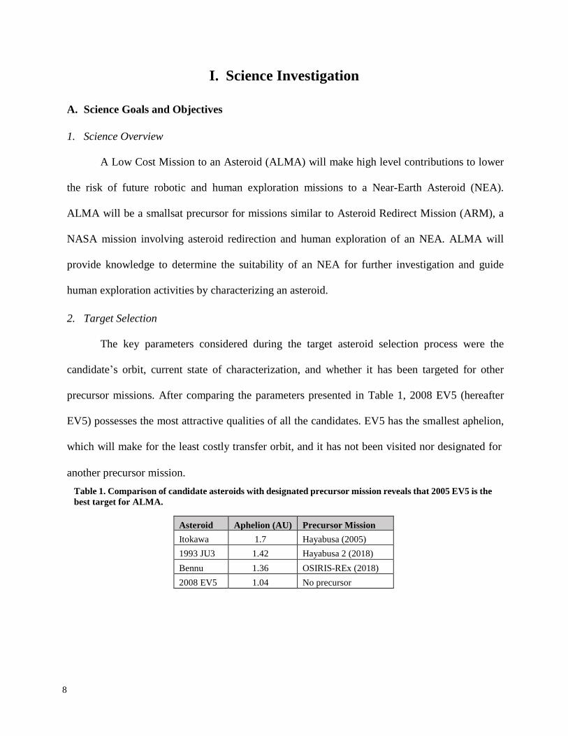
2. Target Selection
The key parameters considered during the target asteroid selection process were the
candidate’s orbit, current state of characterization, and whether it has been targeted for other
precursor missions. After comparing the parameters presented in Table 1, 2008 EV5 (hereafter
EV5) possesses the most attractive qualities of all the candidates. EV5 has the smallest aphelion,
which will make for the least costly transfer orbit, and it has not been visited nor designated for
another precursor mission.
Table 1. Comparison of candidate asteroids with designated precursor mission reveals that 2005 EV5 is the
best target for ALMA.
Asteroid Aphelion (AU) Precursor Mission
Itokawa 1.7 Hayabusa (2005)
1993 JU3 1.42 Hayabusa 2 (2018)
Bennu 1.36 OSIRIS-REx (2018)
2008 EV5 1.04 No precursor

9
If future exploration missions to EV5 fail, the current state of EV5’s characterization may
be to blame. Information about EV5’s physical properties are derived only from Earth-based
observations, which have yielded a mass estimate and a normal albedo, with 33% uncertainty in
each1. EV5 is a potential target for ARM. With such large uncertainties of the target properties,
ARM will risk mission failure or be forced to use large development margins. Given the low
surface resolution from delay-Doppler images, evident in Figure 1, there is not even the
guarantee that a suitable boulder can be found on EV5, so designing ARM to redirect one would
incur large risks. The mineral composition of EV5 is undetermined due to the ambiguous normal
albedo of EV5, which could compromise ARM’s mission objective to collect water-rich
carbonaceous asteroid material1,2. A better characterization will not be obtained unless a remote
sensing mission such as ALMA is flown. ALMA’s detailed characterization of EV5 will put to
rest the aforementioned uncertainties that threaten the success of ARM or other crewed asteroid
missions to EV5.
Figure 1. Delay-Doppler images from Arecibo (modified) have low surface resolutions, evidence of the
poor characterization knowledge of EV5 (Ref. 1).
ALMA will conduct an in-depth characterization of EV5. This involves determining the
rotational period, rotational axis, albedo, mass properties, elemental composition and abundance,
and topography at the respective resolutions necessary for an estimate of sufficient confidence to
determine the suitability of EV5 for future missions. Knowledge gained from ALMA will directly
reduce implementation and mission risks for human exploration missions to EV5.

10
3. Science and Measurement Objectives
Successful completion of the ALMA science objectives will enable ARM, or similar
missions, to demonstrate asteroid deflection techniques for planetary defense, collect water-rich
carbonaceous asteroid material, demonstrate resource utilization methods, and give crews the
requisite knowledge for safe surface interactions. Expected uncertainties, after the science
investigation, for rotation axis angle, albedo, and dimensions are derived from the minimum
requirements to complete the science objectives. Those minimum requirements are based on the
improvements from Earth-based observations that are possible given the mission budget and the
mission architecture. The uncertainty for each measurement is listed in Table 2.
Objective 1 is to determine the rotational period and rotation axis of EV5. The rotational
period is currently estimated to be 3.725 ± 0.001 rotations per hour and the obliquity is estimated
to be 180° ± 10° due to a retrograde rotation1,3. More accurate measurements will yield a greater
understanding of EV5’s orbit and aid future exploration missions.
Objective 2 is to determine the normal albedo over the entire surface of EV5. The albedo
is currently estimated to be 0.12 ± 0.04. ALMA will obtain the necessary information to determine
the albedo to less than 15% uncertainty, which is half the uncertainty of Earth-based observations.
The albedo will be used to determine EV5’s taxonomy using Tholen classification.
Objective 3 is to determine the mass properties of EV5, including the dimensions, bulk
density, mass, and moments of inertia. Accurate mass properties will create confident models of
the asteroid redirection process and cut design margins, which will reduce mission and
implementation risk. ALMA will verify the internal structure through measurements of the
rotational period, mass concentration, mass distribution, and surface gravity. The internal structure
of EV5 is thought to be a rubble-pile, which means that it could contain large interior voids

11
which may be prone to disruption1. The internal structure is important to understand because the
redirection process and human surface interactions may disrupt the structural equilibrium,
causing EV5 to break apart. This would be a catastrophic event, jeopardizing the mission.
Objective 4 is to determine the composition and abundance of minerals on EV5. Mineral
information will be combined with the measured albedo from Objective 2 to determine the Tholen
classification of EV5. A detailed understanding of mineral deposits will also allow scientific areas
of interest to be highlighted for a crewed mission.
Objective 5 is to determine the surface topography of EV5. A topographic map can be
constructed from stereogrammatry, a 3D stereo model technique where two images are obtained
from two different look directions under the same lighting conditions5,6. Another map will be
constructed from radar altimetry data for redundancy. A detailed map will allow humans to
navigate to and conduct science on the aforementioned areas of interest in a safe manner.

12
Table 2. ALMA’s science objectives flow directly from the RFP and will directly contribute to lowering the risk of human exploration missions to EV5 and determine the suitability of a target for redirection2.
ALMA Science Objective
ALMA Measurement Objective
Map - Altitude ALMA Measurement
Requirement
ALMA
Inst.
Instrument Requirement ALMA Science Data and
Analysis Products
Science Impact
1
Rotation Period and
Rotation Axis
Determine rotation period to < 0.01%
uncertainty
1 - HASK
Image EV5 facing nadir
FC
1 Hz imaging with clear filter • Rotation period and rotation
axis
• Global image map
• Greater understanding of
EV5 orbit
• Determine suitability of
target for redirection Determine the rotation axis to < 2˚
2
Normal Albedo
Determine albedo to < 15% uncertainty 1 - HASK
Image EV5 facing nadir FC
Image with clear filter • Normal albedo
• Global image map
• Tholen classification
3
Mass Properties
Determine dimensions to < 5%
uncertainty
1 - HASK Image EV5 facing nadir
FC Image with clear filter • Surface gravity field
• Mass, density, MOI
• Shape model of EV5
• Determine suitability of
target for redirection
Determine mass to < 2% uncertainty
2 - HASK Measure X-band Doppler shifts
HGA Send and receive radio signals
Determine bulk density to < 5%
uncertainty
3,4,5 - LASK
Measure VNIR spectrum with
resolution < 1m/pixel
FC
Image using 7 color and 1 clear
optical bandpass filters from 400
nm - 1050 nm
Measure Gamma ray lines to a
depth of 50cm
GRS
Energy resolution: 0.3% at 1332
keV, energy range: 10 eV – 1
MeV
4
Mineral Composition
and Abundance
Find and identify deposits of minerals
3,4,5 - LASK
Measure VNIR spectrum with
resolution < 1m/pixel
FC
Image using 7 color and 1 clear
optical bandpass filters from 400
nm - 1050 nm
• Global VNIR map
• Global gamma ray map
• Tholen classification
• Determine suitability of
target for redirection
• Guide human exploration
activities by highlighting areas
of scientific interest for further
investigation
Determine abundance of minerals Measure Gamma ray lines to a
depth of 50cm
GRS
Energy resolution: 0.3% at 1332
keV, energy range: 10 eV – 1
MeV
5
Surface Topography
Determine topographic variations and
identify boulders
3,4,5 - LASK
Stereogrammatry: 2 global maps (
+15˚ and -15˚ from nadir) with
resolution < 1m/pixel
FC
Image with clear filter • Global topographic map
• Shape model of EV5
• Guide human exploration
activities by accessing
dangerous topography
Measure radar Doppler shifts RA
Send and receive radio signals

13
4. Measurement Requirements
ALMA measurement requirements are derived directly from our science objectives and
take place over two different mapping altitudes. Table 2, on the previous page, is a comprehensive
view of how the science objectives influence the measurement requirements and trickle down to
the instrument requirements.
Two High Altitude Station Keeping (HASK) maps at an altitude of 1276 m from the surface
of EV5 are required for Objectives 1, 2, and 3, because the whole body must be in-frame. The
HASK altitude was determined based on the measurement objectives and the FOV constraints
from the ALMA Framing Camera (Section B.1). In order to maximize spatial resolution, 1276 m
is the lowest possible altitude that will ensure the FOV will allow for the entire face of the asteroid
to be in the frame when centered with a conservative 0.5° pointing error.
Three Low Altitude Station Keeping (LASK) maps at an altitude of 500 m from the surface
of EV5 are required for Objectives 3, 4, and 5. The LASK altitude was derived from the one year
ALMA mission life constraint and the surface resolution requirement. After six months of transit
and a one month margin, the science operations are limited to five months. There is an upper
limit to the data bandwidth that can be transmitted, given the capabilities of the Deep Space
Network, the design of the high gain antenna, and the transmission power. Each image in a
mapping swath must have a 20% overlap in coverage and a surface resolution of less than 1
m/pixel. The image overlap requirement is baselined from Dawn, which completed successful
characterizations of both Vesta and Ceres. The resolution requirement comes from the centimeter-
level characterization required for the boulder capture option for ARM8. The optimal altitude for
LASK is 500 m, because it satisfies all constraints and requirements without any additional risk.
The asteroid dimensions can be derived from images at a known distance from the target.
The mass and bulk density can be derived from a multitude of sources, however, the most precise

14
technique for determining mass is through examining the X-band Doppler shifts of the signals sent
by ALMA’s high gain antenna (HGA) at EV54,6. The frequency shifts are a byproduct of the
gravitational perturbations related to the mass of an asteroid4. This will reveal the mass
concentration and the mass distribution of EV5 to less than 2% uncertainty, significantly more
accurate than Earth-based observations, as is evident in Figure 2. Bulk density can be estimated to
less than 5% uncertainty by pairing subsurface measurements of gamma-ray lines yielding
elemental abundances with a map of mineral composition5. The accuracy of the mass and density
can be cross-checked using the dimension measurements. Moments of inertia can be derived from
the mass concentration and mass distribution. ALMA’s multifaceted approach to determining the
mass properties inspires a high level of confidence in the quality of the science return.
Figure 2. Distribution of the relative accuracy of mass estimates obtained with four different methods: (a)
orbit deflection during close encounters, (b) planetary ephemeris, (c) orbit of natural satellites or spacecraft
(gray bar), and (d) indirect determination of density converted into mass4. It is clear that ALMA will be
able to provide a mass estimate that is the most likely to be accurate of any remote sensing method.

15
To find and identify deposits of minerals, the surface of EV5 must be mapped according
to the Eight-Color Asteroid Survey required for Tholen classification which requires eight
broadband filters covering wavelengths from 340 nm to 1040 nm9. EV5 will most likely be a Type-
C asteroid, given the information from Earth-based observations1. The asteroid spectra for Type-
C shown in Figure 3 reveals that reflectivity effectively flat lines after 1000 nm. Detecting
wavelengths far beyond 1000 nm will not yield additional useful information for Type-C
asteroids. In the event that there are other trace elements, they will be picked up by gamma ray
spectrometry. Optical bandpass filters covering wavelengths from 400 nm to 1050 nm, which fall
in the visible and near-infrared spectrum (VNIR), will be sufficient to meet measurement
requirements in Table 2. To measure the abundance of minerals which compose EV5, gamma ray
lines will be measured to a depth of 50 cm (Ref. 7). The VNIR and gamma ray data will be of high
spatial and spectral resolution, respectively, which can be fused together to yield a better product
of both high spatial and spectral resolution.
Figure 3. Asteroid spectra and matching meteorite types5. ALMA spectroscopy is customized to detect the
wavelength required to identify minerals on a carbonaceous asteroid, which EV5 is believed to be.

16
5. Baseline Science Scenario
The ALMA baseline science scenario returns the measurements of EV5 necessary to
determine the suitability of further exploration and redirection, whether the target is the entire
asteroid or a boulder from the surface, to guide human exploration missions. ALMA will obtain
complimentary measurements derived from several different techniques in order to return the
highest quality data possible for a low-cost mission while maintaining minimal risk. There will be
a total of 5 maps in the baseline science scenario yielding data and products crucial to
characterizing EV5. Each map has been denoted in Table 2 on page 13. The complete science
operations timeline is in Section II.B.1.
For Map 1, ALMA will take images of EV5 at HASK at a surface resolution of 38 cm/pixel
(Section B.1) facing nadir as EV5 rotates for Objectives 1, 2, and 3. EV5 has an effective obliquity
of 10°, so shadow regions will not be a problem at any point in EV5’s orbit. The image data sent
back to the ground team will be used to create a global image map. The dimensions will have an
uncertainty of 1.08%, based on the uncertainty of the radar altimeter (Section II.A.6). The normal
albedo is a function of the diameter, and will have an uncertainty of 14.26%. For Map 2, ALMA
will orient the HGA to nadir and measure Doppler shifts to support Objective 3. Maps 1 and 2 will
take 7.45 hours to complete and are expected to yield 4.05 GB of data total.
For Maps 3, 4, and 5, ALMA will image EV5 in the VNIR spectrum at a surface resolution
of 15 cm/pixel (Section B.1) and collect gamma ray line measurements to a depth of 50 cm at
LASK over 2 swaths per map, covering 230 m per swath, to complete Objectives 3, 4 and 5.
ALMA will start at the center of Swath 1 and move down to the center of Swath 2 as depicted in
Figure 4. Two of the three maps are needed to complete the topography map through
stereogrammatry, however, each map will also include VNIR and gamma ray measurements
to maximize data collection and data redundancy. With respect to nadir, the first map will be

17
+15˚, the second map will be 0˚, and the third map will be -15˚. Each map will take 7.72 hours to
complete and collect an estimated 8.78 GB of data. These three maps will be used to create a
shape model, global VNIR map, gamma ray map, and a topographic map to guide future
exploration endeavors.
Figure 4. ALMA’s science concept of operations maximizes data collection through a redundant approach
which inspires confidence in the quality of science return.
After the completion of each swath, the images will be analyzed using the on-board
computer. The images will be judged on the basis of percent of the asteroid in a shadow region,
maintenance of altitude, and pointing performance. If the images do not meet the criteria, ALMA
will delete the unsatisfactory swath images and reimage the swath up to 2 more times before
moving to the next swath. Once the ground science team receives and examines the data, they will
have the option to request additional, higher resolution images of regions that may not have been

18
covered to satisfaction. This will be an end-of-life operation, designated as a secondary objective,
that will be completed if there are sufficient resources such as power, propellant, and mission cost.
B. Science Implementation
1. Science Payload
ALMA’s payload suite consists of components with a technology readiness level (TRL)
of 9 which ensures dependable, low risk performance based on flight heritage. The suite includes
the Framing Camera (FC) and the Gamma Ray Spectrometer (GRS), shown in Figures 7 and 8,
with specifications in Tables 4 and 5, respectively, on Page 21.
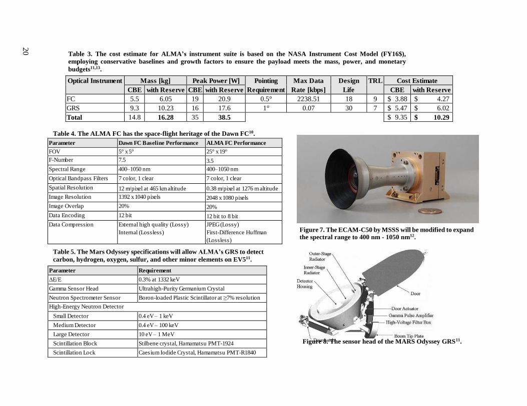
The ALMA FC specifications have been baselined using the Dawn FC specifications. The
Dawn FC was used to characterize Vesta and Ceres in a similar capacity that will be required of
the ALMA FC to characterize EV510. The FC has been classified as TRL 9 because the technology
for the FC requirements in Table 2 on Page 13 is very well understood and because it is a
commercial-off- the-shelf part with some modifications. The FC will be built by Malin Space
Science Systems (MSSS) based on the ECAM-C50, a color 5 megapixel camera with a CMOS
sensor, and an ECAM-NFOV lens with a field-of-view of 25° x 19°. The wavelength range of
the ECAM-C50 will be modified to be 400 nm – 1050 nm in compliance with the requirements
mentioned in Section A.4. The surface resolution at HASK and LASK will be 38 cm/pixel and 15
cm/pixel, respectively, enabling centimeter-level characterization which is required to resolve
boulders on the surface of EV5 (Ref. 8). The FC will be built by a reliable team with experience
from building many space qualified cameras for NASA missions, including Mars
Reconnaissance Orbiter’s Context Camera and Mars Global Surveyor’s Mars Orbiter Camera.
The ALMA GRS specifications have been baselined using the Mars Odyssey GRS
featuring an energy resolution of 0.3% at 1332 keV enabling it to sense gamma ray lines 50 cm

19
below the surface7. The Mars Odyssey possess a “large detector size and a high energy
resolution… which makes it the most likely of any heritage GRS instrument to be able to detect
carbon, sulfur, and other minor elements in carbonaceous asteroids,” (Lim et. al. 2015) as seen in
Figure 5. This capability makes it the most favorable heritage model GRS for the ALMA GRS.
Figure 6 shows that the Mars Odyssey GRS is resilient to background noise and sensitive enough
to detect hydrogen lines due to a high energy resolution from a High-purity Germanium (HPGe)
detector7. The ALMA GRS is planned to be built by Los Alamos National Laboratory, which built
the gamma subsystem and the neutron detector on the Mars Odyssey GRS.
Figure 5. The Mars GRS has a higher detector efficiency due to its large detector size across the board when compared to the MESSENGER GRS, meaning it is more adept at detecting carbon abundance7.
Figure 6. The Mars Odyssey GRS is sensitive enough to detect hydrogen, while remaining undeterred to background noise from the aluminum spacecraft bus7.
Optical Instrument Mass [kg] Peak Power [W] Pointing
Requirement
Max Data
Rate [kbps]
Design
Life
TRL Cost Estimate
CBE with Reserve CBE with Reserve CBE with Reserve
FC 5.5 6.05 19 20.9 0.5° 2238.51 18 9 $ 3.88 $ 4.27
GRS 9.3 10.23 16 17.6 1° 0.07 30 7 $ 5.47 $ 6.02
Total 14.8 16.28 35 38.5 $ 9.35 $ 10.29
Parameter Dawn FC Bas eline Performance ALMA FC Performance
FOV 5° x 5° 25° x 19°
F-Number 7.5 3.5
Spectral Range 400–1050 nm 400–1050 nm
Optical Bandpas s Filters 7 color, 1 clear 7 color, 1 clear
Spatial Res olution 12 m/pixel at 465 km altitude 0.38 m/pixel at 1276 m altitude
Image Res olution 1392 x 1040 pixels 2048 x 1080 pixels
Image Overlap 20% 20%
Data Encoding 12 bit 12 bit to 8 bit
Data Compres s ion External high quality (Los s y)
Internal (Los s les s )
JPEG (Los s y)
Firs t-Difference Huffman
(Los s les s )
Parameter Requirement
ΔE/E 0.3% at 1332 keV
Gamma Sens or Head Ultrahigh-Purity Germanium Crys tal
Neutron Spectrometer Sens or Boron-loaded Plas tic Scintillator at ≥7% res olution
High-Energy Neutron Detector
Small Detector 0.4 eV – 1 keV
Medium Detector 0.4 eV – 100 keV
Large Detector 10 eV – 1 MeV
Scintillation Block Stilbene crys tal, Hamamats u PMT-1924
Scintillation Lock Caes ium Iodide Crys tal, Hamamats u PMT-R1840
20
Table 3. The cost estimate for ALMA’s instrument suite is based on the NASA Instrument Cost Model (FY16$),
employing conservative baselines and growth factors to ensure the payload meets the mass, power, and monetary
budgets11,13.
Table 4. The ALMA FC has the space-flight heritage of the Dawn FC10.
Table 5. The Mars Odyssey specifications will allow ALMA’s GRS to detect
carbon, hydrogen, oxygen, sulfur, and other minor elements on EV511.
Figure 7. The ECAM-C50 by MSSS will be modified to expand the spectral range to 400 nm - 1050 nm12.
Figure 8. The sensor head of the MARS Odyssey GRS 11.

21
The GRS performance is baselined using the Mars Odyssey GRS, while the mass and
power requirements are baselined using the Dawn Gamma Ray and Neutron Detector (GRaND).
The Mars Odyssey GRS was flown in 2001, and there have been many gamma ray spectrometers
flown since then, which is why the GRS is TRL 7. Given the advancements in gamma ray
spectroscopy from 2001 to 2016, mass and power requirements have decreased for a similar
performance. Aspects of the original build are outdated and will require a refresh to 2016
standards. Although the Dawn GRaND utilizes different sensors than the Mars Odyssey GRS for
gamma ray detection, it is a more realistic lower bound for the mass and power requirements.
The NASA instrument cost model has been used with conservative growth factors of 10%
on the mass and power requirements of each instrument shown in Table 3. The design life of the
FC includes 1 year for development and testing plus 6 months of science operations. It is worth
noting that the design life of the ECAM-C50 is 10 years13. The design life of the GRS includes 1
year of testing and development, 1 year of contingency because the Mars Odyssey GRS build is
being updated, and 5 months of science operations.
2. Instrument Testing and Calibration
A battery of instrument tests will ensure ALMA produces the best possible
characterization. Each instrument used for data collection during science operations, including the
HGA and the Radar Altimeter, has a method of verification for their respective requirements as
described in Table 6. Attitude determination will confirm spatial resolution requirements. Tests
will be comprehensive and redundant to flag and determine sources of unexpected behavior and
reduce mission risk. The FC functionality tests will be conducted by Malin Space Science
Systems based on the tests they conduct for the ECAM-C50 during product quality control.
After spacraft integration, the ALMA FC personnel will verify expected operation during power
22
subsystem testing.
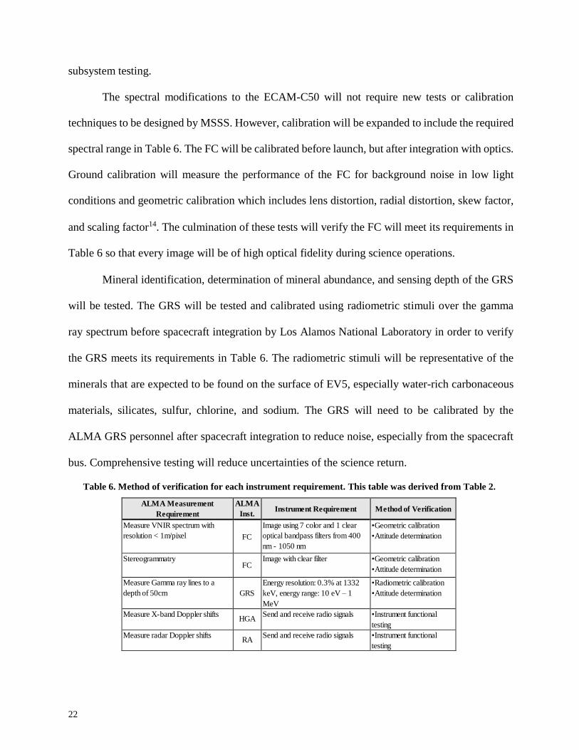
The spectral modifications to the ECAM-C50 will not require new tests or calibration
techniques to be designed by MSSS. However, calibration will be expanded to include the required
spectral range in Table 6. The FC will be calibrated before launch, but after integration with optics.
Ground calibration will measure the performance of the FC for background noise in low light
conditions and geometric calibration which includes lens distortion, radial distortion, skew factor,
and scaling factor14. The culmination of these tests will verify the FC will meet its requirements in
Table 6 so that every image will be of high optical fidelity during science operations.
Mineral identification, determination of mineral abundance, and sensing depth of the GRS
will be tested. The GRS will be tested and calibrated using radiometric stimuli over the gamma
ray spectrum before spacecraft integration by Los Alamos National Laboratory in order to verify
the GRS meets its requirements in Table 6. The radiometric stimuli will be representative of the
minerals that are expected to be found on the surface of EV5, especially water-rich carbonaceous
materials, silicates, sulfur, chlorine, and sodium. The GRS will need to be calibrated by the
ALMA GRS personnel after spacecraft integration to reduce noise, especially from the spacecraft
bus. Comprehensive testing will reduce uncertainties of the science return.
Table 6. Method of verification for each instrument requirement. This table was derived from Table 2.
ALMA Measurement
Requirement
ALMA
Inst.
Instrument Requirement
Method of Verification
Measure VNIR spectrum with
resolution < 1m/pixel
FC
Image using 7 color and 1 clear
optical bandpass filters from 400
nm - 1050 nm
•Geometric calibration
•Attitude determination
Stereogrammatry
FC Image with clear filter •Geometric calibration
•Attitude determination
Measure Gamma ray lines to a
depth of 50cm
GRS
Energy resolution: 0.3% at 1332
keV, energy range: 10 eV – 1
MeV
•Radiometric calibration
•Attitude determination
Measure X-band Doppler shifts
HGA Send and receive radio signals •Instrument functional
testing
Measure radar Doppler shifts
RA Send and receive radio signals •Instrument functional
testing

23
Description
Scientific Value Required Technology
Development
Driving Cost
Mission Risk
Earth-orbiting
Telescope
• Sufficient
characterization of
many asteroids
• No heritage telescope
for this application
• Expensive
payload
development from
low TRL
• The spacecraft
would primarily
stay in earth orbit
• No complicated maneuvers
Remote Sensing
• Sufficient characterization of one asteroid
• No new technologies have to be developed • Potential to use COTS parts
• Δv required to rendezvous with the NEA
• Extensive heritage • Orbital
requirements are
well known
Lander/Impactor
• Excellent characterization of one asteroid
•Landing/impacting system technology must be developed and built from scratch
• Development of landing/impacting system due to low TRL
• Docking complexity (Rosetta) • Difficult to test
low gravity
environments
II. Mission Implementation
A. Technology Development
1. Mission Overview
There are many approaches to designing a smallsat mission that satisfy the goal of the request
for proposal (RFP) of supporting a future asteroid exploration mission. Three distinct mission
architectures were proposed and evaluated based on the RFP requirements: a space-based
telescope, a remote sensing mission, and a lander/impactor mission. A high level trade study
comparing alternative mission architectures, outlined in Table 7, determined that remote sensing
has the most positive set of characteristics, and so it was chosen as ALMA’s mission architecture.
Table 7. A comparison of mission architectures clearly shows why the ALMA team decided on
remote sensing.

24
While in the vicinity of 2008 EV5, the ALMA spacecraft will fully characterize the asteroid
in order to support future exploration missions, crewed or otherwise. Characterization of EV5 will
support future missions by reducing the risk of nearly all facets of the mission. Future missions
will be able to reduce margins, which will reduce risk and cost significantly. In order to support
the science investigation, ALMA will have the requirements detailed in Table 8.
Table 8. The top-level requirements derived from the RFP, mission concept of operations, and feasible
architectures drive the overall spacecraft design towards proven and readily accomplished implementation.
Mission Requirements
Shall utilize smallsat concept by keeping total spacecraft mass below 500 kg
Shall keep total mission cost below $100M FY16 cap
ALMA shall characterize the properties of NEA 2008 EV5 to the accuracies set by the science team
System Requirements
ALMA shall travel to and station keep at 2008 EV5
ALMA shall have an operational life of greater than 1 year
Shall measure VNIR spectrum with resolution < 1/pixel and gamma ray lines to a depth of 50 cm
Subsystem Requirements
Launch vehicle shall deliver ALMA into a TLI in May 2024
ALMA shall communicate with Earth through the DSN in a store and forward architecture
ALMA electronics shall be robust to a TID of 30 krads of radiation
ALMA's ADCS shall control attitude with a pointing requirement 0.3°
ALMA's propulsion system shall provide 2.2 km/s Δv in 2 burns
ALMA's computer shall process 8.78 GB of science data and execute commands autonomously
ALMA's power system shall provide 205 W at peak power to the bus
ALMA shall maintain a bus temperature between 10°C and 25°C
In order to meet these requirements, the ALMA development team has designed a low-
cost, reliable mission. ALMA will launch in late May 2024 on a Minotaur V launch vehicle. The
Minotaur V will put ALMA on a trajectory to perform a flyby of the moon. Shortly after the flyby,
once ALMA is outside of the sphere of influence of the moon, the first of two main engine burns
will occur to put the spacecraft on a Hohmann trajectory to intercept 2008 EV5 188 days later.
When sufficiently close to the asteroid, the second main engine burn combined with a slow
25
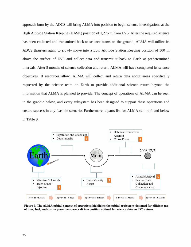
approach burn by the ADCS will bring ALMA into position to begin science investigations at the
High Altitude Station Keeping (HASK) position of 1,276 m from EV5. After the required science
has been collected and transmitted back to science teams on the ground, ALMA will utilize its
ADCS thrusters again to slowly move into a Low Altitude Station Keeping position of 500 m
above the surface of EV5 and collect data and transmit it back to Earth at predetermined
intervals. After 5 months of science collection and return, ALMA will have completed its science
objectives. If resources allow, ALMA will collect and return data about areas specifically
requested by the science team on Earth to provide additional science return beyond the
information that ALMA is planned to provide. The concept of operations of ALMA can be seen
in the graphic below, and every subsystem has been designed to support these operations and
ensure success in any feasible scenario. Furthermore, a parts list for ALMA can be found below
in Table 9.
Figure 9. The ALMA orbital concept of operations highlights the orbital trajectory designed for efficient use
of time, fuel, and cost to place the spacecraft in a position optimal for science data on EV5 return.

Table 9. Complete parts list with mass and contingency to reduce the possibility of mass overruns.
Subsystem Component Mass [kg]
Contingency [%] Mass with
Contingency [kg] TRL
Payload Framing Camera (FC) 5.5 10 6.1 9
Gamma Ray Spectrometer 9.3 10 10.2 7
Structures Bus 15.9 30 20.7 6
Thermal
Solid-State Controller 0.2 12 0.2 7
MLI 1.2 12 1.34 9
Coatings 0 12 - 9
Electric Heaters 0.4 12 0.4 9
Heat Pipes 0.5 12 0.6 6
Radiators 0.3 12 0.3 6
Power
Solar Panels 3.1 5 3.3 9
Li Ion Batteries 2.1 5 2.2 9
Power Control System 0.3 5 0.3 9
Power Distribution System 1.3 5 1.4 9
CDH
Spacewire Data Bus - SPA-S 2 10 2.2 9
RAD 750 computer 0.5 10 0.6 9
SpaceWire interface board 0.5 10 0.6 9
Subsystem Memory Cards 2 10 2.2 7
Mass Memory 1 10 1.1 8
Flight Software 0 10 - 7
Communications
SDST X-band Transponder 2.7 12 3.0 9
X-Band TWTA 2.3 12 2.6 9
X-Band Diplexer 0.6 12 0.7 9
X-Band Switching Cables (x2) 1 12 1.1 9
X-Band Cables (x12) 3.3 12 3.7 9
Low Gain Antenna 0.7 12 0.8 9
High Gain Antenna 10.7 12 12.0 9
ADCS
Sun Sensor (x4) 0.2 7 0.2 9
Star Tracker (x2) 0.3 7 0.3 8
IMU 0.7 7 0.7 9
RCS Thrusters (20N) (x4) 2.5 7 2.7 9
RCS Thrusters (1N) (x8) 2.6 7 2.8 9
Radar Altimeter 1.4 7 1.5 9
Propulsion
Main Engine 4.5 12 5.0 9
Fuel Tank 8.6 12 9.6 9
Oxidizer Tank 11 12 12.3 9
Plumbing 4.2 12 4.7 -
Pressurant Tank (x2) 3 12 3.4 9
Hydrazine 144.3 - - 9
Oxidizer 83.3 - - 9
Pressurant 1.1 - - 9
Total
Mass including contingencies 120.8
Dry Mass w/ 30% contingency 157.09
Launch Mass 404.1
26

27
2. Orbit
In order to successfully complete the remote sensing activities, the spacecraft must first
reach the asteroid. 2008 EV5 is a good target because it has an orbit that is similar to Earth's, albeit
at a seven degree inclination. This similarity reduces the amount of propellant required, which will
save money and mass in order to meet the budget and smallsat requirements. A Hohmann transfer,
chosen because it is the most efficient impulsive transfer orbit for orbits with relative sizes of that
of EV5 and Earth, will be used to reach 2008 EV5 after a lunar flyby is utilized to account for the
inclination change. Table 10 below highlights some important dates for the orbital profile of
ALMA.
Table 10. Important dates during ALMA’s orbital mission.
Launch 05/27/2024
Lunar Flyby 05/30/2024
First Hohmann Burn 05/31/2024
Second Hohmann Burn 12/03/2024
Asteroid Arrival 12/04/2024
The flyby is possible because the Minotaur V translunar injection (TLI) can put ALMA at
an inclination of 14.39° to the ecliptic, while the moon is at 5.14°. Since the desired inclination is
7.4°, the Moon can be used to pull ALMA down into the correct desired inclination. Because it
will occur immediately before a Hohmann transfer, the flyby will need to occur as close as possible
to the Moon being in its Third Quarter phase. The launch date is somewhat flexible; more research
will need to be conducted into the specific consequences of launching any number of days early
or late, but at this time it is believed that the effects of leaving a day early or late will be
insignificant. The desired Hohmann launch date was found to be May 30, 2024, which
coincidentally is the day that the Moon is in its Third Quarter phase.
Because of the nature of the lunar flyby that ALMA will be utilizing, the moon’s gravity
will only be used to perform an inclination change and will not increase the in-plane velocity of

28
ALMA. With that information in mind, the Hohmann orbit calculations have been done assuming
that no inclination change will be needed during the two necessary burns.
Using the characteristic energy for a TLI provided by the Minotaur V launch vehicle team
of -1.89, the velocity before and after the lunar flyby was calculated15. The first required Hohmann
burn of 1.78 km/s will be performed after ALMA has safely left the sphere of influence of the
moon with the correct inclination to intercept EV5. A depiction of the lunar flyby with the relative
angles can be seen below in Figure 10.
Figure 10. ALMA will utilize the Moon to match the 7.4 degree inclination of 2008 EV5.
To achieve the inclination change required, ALMA’s perilune will be at a distance of
51,292 km from the center of the Moon, which is within the sphere of influence of 60,000 km.
After the initial Hohmann burn, ALMA will be on an orbit to intercept 2008 EV5 in 188 days. An
overview of the orbit can be seen below in Figure 11.

29
Figure 11. Overview of ALMA's efficient Hohmann transfer to rendezvous with 2008 EV5
Once in the vicinity of EV5, another burn of 0.401 km/s will match ALMA’s orbit to that
of EV5 and allow science investigations to begin. A table of the Δv requirements for the major
orbital maneuvers can be found below in Table 11.
Table 11. Orbital maneuver Δv budget
Maneuver
Δv [km/s]
First Hohmann Burn
1.78
Second Hohmann Burn
0.40
Total
2.18
3. Launch Vehicle
3.1 Definition
ALMA’s orbital trajectory architecture imposes strict requirements on the launch vehicle
selection process as seen in Table 12. The concept of using the lunar flyby to reduce the propellant
mass of the spacecraft, to achieve a smallsat classification, means the launch vehicle shall deliver
ALMA to a TLI. ALMA also cannot produce any Δv other than what is necessary for the transfer

30
to 2008 EV5 without growing significantly in mass. Therefore, the spacecraft will rely on the
launch vehicle energy for the lunar flyby. Any vehicle candidates shall accommodate an estimated
launch mass of 400 kg based on the average of heritage interplanetary spacecraft with respect to
the ALMA payload mass. The launch vehicle payload fairing must also house the spacecraft bus’s
volume when fully integrated without violating the two meter diameter antenna on the spacecraft’s
side. Besides the high energy and mass capability requirements, the launch must also occur within
only a few days of the May 2024 target date based on the positions of the Earth, Moon, and 2008
EV5 in order to achieve the correct lunar flyby trajectory.
Table 12. The mission derived requirements on the launch vehicle converge the selection trade space to a reliable, high-performance vehicle reducing the risk of launch failure found in lower technology options.
Requirements Description Launch Vehicle Specifications
Final Target Orbit Direct transfer to Lunar Flyby Trans-Lunar Injection
Spacecraft On-Board Propulsion Limited propellant availability No parking orbit
Estimated Payload Mass Deep space probe with smallsat
classification of <500 kg
400 kg launch capability
Key Volume Accommodation Largest spacecraft dimension in
stowed launch configuration Payload fairing dynamic volume
dimension >2m
Launch Date Precision Lunar cycle limits flyby
opportunities
± 1 day
Cost $100M mission budget Medium performance class vehicle
Heavy-class vehicles capable of reaching the orbital target are not within the mission
budget even with ALMA utilizing a primary ride sharing opportunity such as those offered by
ULA’s Atlas V / Delta IV Dual Spacecraft System or external payload carrier XPC. ALMA’s mass
and volume are also beyond the capabilities of smaller, standard multi-payload adaptors, where
the spacecraft would be a secondary payload, such as those commercially available from ULA’s
Atlas and Delta, Space X’s Falcon 9, and Orbital ATK’s Antares16. As a secondary payload on
these vehicles, the issue of missing the launch date would be essentially guaranteed and the
program level challenges of contracting other spacecraft payloads to be delivered on time adds risk
to the mission operations. Considering the specific orbital delivery to an interplanetary trajectory,

31
precise time constraints for lunar and asteroid rendezvous, and the volumetric needs of a larger
smallsat, ALMA should fly as a primary payload on its own launch vehicle.
3.2 Minotaur V
The reliable Minotaur V has been selected to carry ALMA to the initial orbit injection. The
Minotaur V is a high performance derivative of Orbital ATK’s Minotaur IV rocket built to
“provide a cost-effective capability to place small spacecraft into high energy trajectories,” making
the vehicle ideally suited for ALMA17. Adding another stage to the reliable Minotaur IV for more
performance, the V is built with five solid stages based on the Peacekeeper intercontinental
ballistic missile and flight proven STARTM motors. Considered overpowered for common
smallsat missions, the Minotaur V is capable of delivering 440 kg of payload to TLI. The
consistent architecture across the Minotaur family, including similar avionics, structure, and
payload accommodation, leverages significant heritage into the TRL 9 vehicle configuration
shown in Figure 12 as well as in the appendix. Approximately 36 kg are available after ALMA is
integrated for the use of smaller ride share customers, a potential cost savings of up to $2.45M
based on mass, or as an additional 9% launch mass margin policy to be determined in Phase B
risk analysis.

32
Figures 12. The high reliability of the Minotaur V configuration is apparent from the reuse of flight proven components inherited from the successful Minotaur IV15.
The Minotaur V is uniquely capable of providing the necessary energy for a smallsat
interplanetary mission while staying within the programmatic constraints of ALMA. Nominal
performance figures of merit for the launch vehicle with respect to the ALMA orbital concept of
operations are found below in Table 13. The Minotaur V is extremely cost effective with near
escape trajectory capability for the reasonable purchase estimate of $30M. Use of the Mid-
Atlantic Regional Spaceport will ensure the best teams are available for ALMA’s integration as
well. This is due to the fact that Orbital ATK has baselined Wallops Flight Facility for Minotaur
V launches18. These teams, who are accustomed to working within the fast-paced architecture of
robotic precursor missions, will be suited to ensure minimal schedule and cost disturbances occur
up to launch.

33
Table 13. The orbital figures of merit for the Minotaur V bound show the feasibility of the launch vehicle selection achieving ALMA mission requirements 15. Orbit Type
Launch Site
Perigee [km] Apogee [km] Inclination [°] Arg. Of
Perigee [°] C3 [km2/s2]
Performance [kg]
TLI WFF 200 408556 37.83 180 -1.89 432
4. Configurations
4.1 Launch Vehicle Integration
ALMA will be integrated in the standard Minotaur V payload fairing which will
accommodate the spacecraft as a primary payload as well as optional secondary ride sharing
customers. Eliminating some of the available payload fairing volume, the fifth stage will interface
to ALMA through the Payload Attach Fitting, an anisogrid structure which connects to the
standard 803 mm diameter spacecraft interface ring on ALMA. Electrical interfaces supported by
Orbital ATK will provide power and battery charging, discrete telemetry and commands, and
separation indications to the spacecraft. Volume design constraints on the spacecraft bus shown
in Figure 13 are moderate as the fairing is designed for small and medium class satellites and
already includes negotiable volume around the fifth stage for ride shares.

34
Figures 13. The dyanamic volume envelope for ALMA shown within the Minotaur V payload fairing readily encapsulates the spacecraft as well as optional ridesharing payloads15.
4.2 Structure
The bus of the ALMA spacecraft will be a cubic skin-frame structure, which means that an
internal skeletal network will support the skin of the spacecraft. This common design will be
utilized because of its low complexity meaning reduced development costs. The cubic design is
easy to manufacture and allows for plenty of surface area for component mounting. The skin-frame
design will support the large loads experienced during launch by carrying the axial, torsion, and
bending loads in the internal frames while carrying the shear loads in the skin. Due to the need for
high strength and low cost, aluminum will be used to make the internal skeletal network of the
spacecraft.
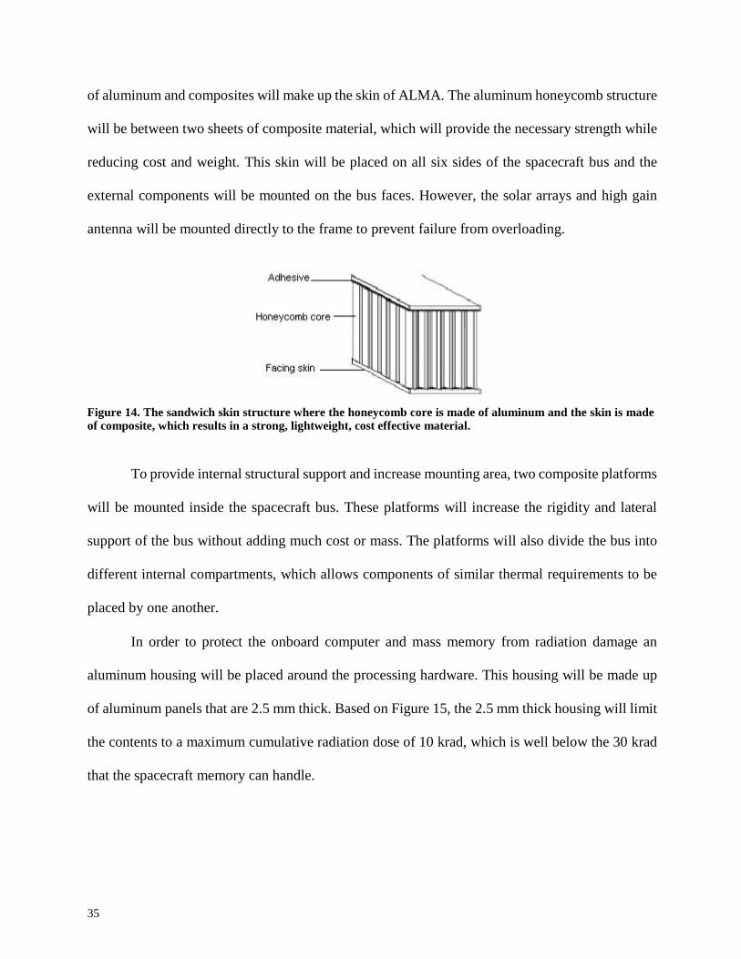
Since the skin will have to support shear forces, a sandwich structure will be utilized in the
skin with two layers of solid material on the outside of a honeycomb core, which can be seen in
Figure 14. In order to reduce cost while maximizing the strength per unit weight, a combination
35
of aluminum and composites will make up the skin of ALMA. The aluminum honeycomb structure
will be between two sheets of composite material, which will provide the necessary strength while
reducing cost and weight. This skin will be placed on all six sides of the spacecraft bus and the
external components will be mounted on the bus faces. However, the solar arrays and high gain
antenna will be mounted directly to the frame to prevent failure from overloading.
Figure 14. The sandwich skin structure where the honeycomb core is made of aluminum and the skin is made of composite, which results in a strong, lightweight, cost effective material.
To provide internal structural support and increase mounting area, two composite platforms
will be mounted inside the spacecraft bus. These platforms will increase the rigidity and lateral
support of the bus without adding much cost or mass. The platforms will also divide the bus into
different internal compartments, which allows components of similar thermal requirements to be
placed by one another.
In order to protect the onboard computer and mass memory from radiation damage an
aluminum housing will be placed around the processing hardware. This housing will be made up
of aluminum panels that are 2.5 mm thick. Based on Figure 15, the 2.5 mm thick housing will limit
the contents to a maximum cumulative radiation dose of 10 krad, which is well below the 30 krad
that the spacecraft memory can handle.

36
Figure 15. The absorbed radiation for a sheet of aluminum as a function of thickness, which was used to design a protective housing for the onboard computer and memory. Generated using SPENVIS.
4.3 Spacecraft Layout
The configuration of the various subsystem components on the bus was chosen to reduce
complexity, maintain moment requirements, and ease the plug and play assembly. The only
elements outside of the protective bus skin are the payload instruments, sensors, thrusters, radiator,
and high gain antenna. To accommodate the large parabolic dish and maintain the launch center
of mass constraints, ALMA will be integrated with the Minotaur V with the antenna pointing
upwards in the fairing and the standard payload attach fitting directly opposite as seen in Figure
16. Also, the reaction control thrusters are mounted on booms to accommodate the thruster exhaust
and reinforce control effectiveness. The two solar panels are on deployable arms which will rotate
on a single axis and fold up in the stowed configuration. Internally, the electronic elements are
mounted directly below the payload, but inside of the bus, to reduce size and complexity of the
wiring harness. A large percentage of the bus volume will go to the propulsion system tanks and
plumbing which, alongwith the different temperature requirements of individual subsystems,

37
drive locations of the intercostal support planes and divide the bus into three compartments. The
main engine is the final component extending below the spacecraft.
Figure 16. The ALMA spacecraft utilizes an efficient configuration to integrate the proven flight components
while remaining within the volume constraints of the payload fairing.
Fuel Tank
38
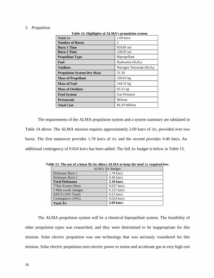
5. Propulsion Table 14. Highlights of ALMA's propulsion system
Total Δv 2.69 km/s
Number of Burns 2
Burn 1 Time 824.85 sec
Burn 2 Time 128.95 sec
Propellant Type Bipropellant
Fuel Hydrazine (N2H4)
Oxidizer Nitrogen Tetroxide (N2O4)
Propulsion System Dry Mass 31.30
Mass of Propellant 228.63 kg
Mass of Fuel 144.31 kg
Mass of Oxidizer 83.31 kg
Feed System Gas Pressure
Pressurant Helium
Total Cost $6.29 Million
The requirements of the ALMA propulsion system and a system summary are tabulated in
Table 14 above. The ALMA mission requires approximately 2.69 km/s of Δv, provided over two
burns. The first maneuver provides 1.78 km/s of Δv and the second provides 0.40 km/s. An
additional contingency of 0.024 km/s has been added. The full Δv budget is below in Table 15.
Table 15. The use of a lunar fly-by allows ALMA to keep the total Δv required low.
ALMA Δv Budget
Hohmann Burn 1 1.78 km/s
Hohmann Burn 2 0.40 km/s
Total Hohmann 2.18 km/s
776m Science Burn 0.027 km/s
3 90m swath changes 0.121 km/s
ADCS (10% Total) 0.22 km/s
Contingency (10%) 0.024 km/s
Total Δv 2.69 km/s
The ALMA propulsion system will be a chemical bipropellant system. The feasibility of
other propulsion types was researched, and they were determined to be inappropriate for this
mission. Solar electric propulsion was one technology that was seriously considered for this
mission. Solar electric propulsion uses electric power to ionize and accelerate gas at very high exit

39
velocities. This high exit velocity affords a very high specific impulse, which is desirable due to
the stringent size and cost constraints of the ALMA mission. A high specific impulse greatly
reduces the mass of propellant needed. However, in the case of solar electric propulsion, the high
specific impulse comes at the cost of thrust. Solar electric propulsion offers very low thrust, on the
milliNewton to Newton scale. ALMA is a precursor mission with the intent of assisting human
asteroid missions, and the thrust offered by solar electric propulsion is too low to fulfill this goal,
as it will increase mission duration so much that the science done by ALMA will not be useful in
time for future missions.
The bipropellant system used by ALMA will use hydrazine as the fuel and nitrogen
tetroxide (MON-3) as the oxidizer. A monopropellant system was considered, but the specific
impulse (Isp) offered by such systems was too low. Bipropellant systems offer high thrust at
relatively high specific impulse. Bipropellant systems also have extensive heritage on deep space
missions. The high thrust of a bipropellant system will allow ALMA to complete its mission in a
short time frame, and the high specific impulse will reduce the total mass of propellant needed.
ALMA will launch with 144.3 kg of hydrazine and 83.3 kg of nitrogen tetroxide (NTO). The
spacecraft has 104.1 kg of hydrazine for the Hohmann burns, including contingency; the rest of
the hydrazine is available to the ADCS system, which will use the fuel to complete the necessary
maneuvers to complete ALMA’s science mission.
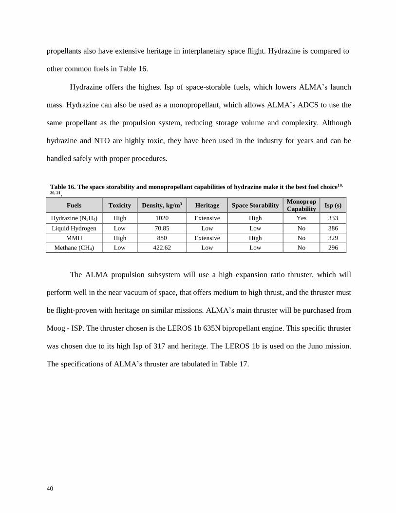
Hydrazine and NTO are desirable propellants due to their storability and heritage19. Liquid
propellants stored above their boiling temperature will vaporize, which is a common problem with
many propellants and oxidizers. NTO and hydrazine are space storable, and do not require
expensive tanks and cryogenic or pressurant technology to prevent boil-off19. These two
40
propellants also have extensive heritage in interplanetary space flight. Hydrazine is compared to
other common fuels in Table 16.
Hydrazine offers the highest Isp of space-storable fuels, which lowers ALMA’s launch
mass. Hydrazine can also be used as a monopropellant, which allows ALMA’s ADCS to use the
same propellant as the propulsion system, reducing storage volume and complexity. Although
hydrazine and NTO are highly toxic, they have been used in the industry for years and can be
handled safely with proper procedures.
Table 16. The space storability and monopropellant capabilities of hydrazine make it the best fuel choice19,
20, 21.
Fuels
Toxicity
Density, kg/m3
Heritage
Space Storability Monoprop
Capability
Isp (s)
Hydrazine (N2H4) High 1020 Extensive High Yes 333
Liquid Hydrogen Low 70.85 Low Low No 386
MMH High 880 Extensive High No 329
Methane (CH4) Low 422.62 Low Low No 296
The ALMA propulsion subsystem will use a high expansion ratio thruster, which will
perform well in the near vacuum of space, that offers medium to high thrust, and the thruster must
be flight-proven with heritage on similar missions. ALMA’s main thruster will be purchased from
Moog - ISP. The thruster chosen is the LEROS 1b 635N bipropellant engine. This specific thruster
was chosen due to its high Isp of 317 and heritage. The LEROS 1b is used on the Juno mission.
The specifications of ALMA’s thruster are tabulated in Table 17.

41
Table 17. ALMA's propulsion system thruster is reliable and robust while providing a relatively high Isp.
Propellant Hydrazine/NTO (MON)
Thrust (Steady-state) 635 N
Inlet Pressure Range 15-20 Bar
Throughput 4170 kg
Demonstrated Restarts 70
Oxidizer/Fuel Ratio 0.85
Valve Power 45 Watts
Mass 4.5 kg
Isp 317 sec
Max Steady State Firing 2520 sec
The propulsion subsystem requirements dictate the use of two steady-state thruster burns,
the first of which is 825 seconds, and the second of which lasts 129 seconds. ALMA’s main engine
is capable of up to 2520 seconds of steady state burning, so the engine will be more than capable
of achieving the required burns. The thruster features fault avoiding valves, which are spring
loaded to prevent the valves from getting stuck. This ensures that the main thruster valves
cannot get
stuck.
Figure 17. ALMA's main thruster built by Moog – ISP22
The ALMA propulsion system will employ a pressurized feed system to mix the fuel and
oxidizer together in the combustion chamber. Pressurized feed systems are reliable and relatively

42
simple19. Gas pressure feed systems use a pressurized gas to force propellants out of their
tanks in a controlled manner. ALMA’s feed system will use helium as the pressurant, as helium
is non-reactive with both the oxidizer and fuel, and will only slightly dissolve into the propellant
over the course of the mission19.
The ALMA propulsion system will utilize a plumbing system based off of bipropellant
systems from similar missions. A simplified version of ALMA’s propulsion system is depicted in
the block diagram below. The propulsion system is composed of nine pyrovalves (PV), five
standard accuracy pressure transducers (SAPT), two check valves (CV), a pressure regulator (PR),
and filters (F). The system will also include multiple maintenance valves which include relief
valves, fill, and drain valves.
The pyrovalves have two initial settings: normally open (NO) and normally closed (NC).
ALMA will begin its mission with all pyrovalves in their default state, which will depend on their
function. Once separation from the launch vehicle is achieved, the normally closed pyrovalves will
open to allow fluid flow. This will allow the ADCS subsystem to conduct its initial control burn
and for hydrazine and NTO to flow to the liquid apogee engine (LAE). In the event of a failure
within the system, the normally open pyro valves can be closed to prevent flow23,24.
The system check valves prevent fluid from flowing backwards toward the helium tanks.
Check valves only allow for flow in one direction, and their burst pressure is far above the
operating pressure of the propulsion system. The pressure transducers monitor the fluid pressure
within the system at five key points, using the piezoresistive effect, to ensure fluids are at the
correct pressure. The system filters ensure that there are no contaminants in the fluid stream.
ALMA will also carry multiple fill and drain valves for pre-launch tank filling, and relief valves
to correct any potential pressure anomalies27.

43
Figure 18. ALMA's propulsion system diagram which is based off of existing, successful bipropellant systems25
ALMA will use spherical tanks to contain the fuel, oxidizer, and pressurizing gas. Spherical
tanks minimize the dry mass of the propulsion system due to their minimal surface area. Both the
fuel and the oxidizer tank will be made of grade IV annealed titanium. This is the vendor
recommended metal for storing both the fuel and the oxidizer – titanium will resist corrosion and
is strong enough to store the propellants at high pressure26. The NTO, hydrazine, and helium tanks

44
will be purchased from Orbital ATK. Orbital ATK was chosen as the tank vendor due to their
extensive heritage and available selection of tanks that meet ALMA’s specifications. The helium
tank will be bought directly from Orbital ATK, while the fuel and oxidizer tanks will be custom
made to minimize the dry mass of the spacecraft and fit volume constraints. The tank propellant
management devices are shown above in Figure 19.
Figure 19. ALMA’s tanks use an all titanium PMD. The PMD uses simple vane technology to allow propellants
to flow “uphill” against the acceleration of the spacecraft, ensuring continuous flow of propellant29.
Table 18. ALMA uses TRL 9 parts with extensive heritage. This ensures low risk and cost23,24,27.
Part Manufacturer Heritage TRL
Main Engine Moog ISP Juno 9
Tanks Orbital ATK Extensive 9
SAPT Moog Bradford Galileo IOV, GB2, etc 9
Pyrovalve Airbus Extensive 9
Check Valve Airbus Extensive 9
Thruster Valve Moog ISP Juno 9
ALMA’s propulsion system is low risk; all parts in the system are TRL 9, and the system
has been designed to maximize fault tolerance and avoidance. All of ALMA’s parts have been
tested rigorously and extensively, which makes component failure very unlikely. The plumbing

45
and tanks of the system are leak-proof to pressures far higher than the operating pressures of this
mission. The subsystem parts and their respective manufacturers are tabulated above in Table 18.
The greatest potential risks to ALMA’s propulsion system are in Table 19.
Table 19. ALMA is a low risk mission with potential failures addressed26.
Failure
Corrective Action
Mission Effect
Likelihood
Main Engine Failure
None
Failure
Low
Loss of flow control
Close pyrovalve
Increased duration
Medium to Low
Loss of SAPT
signal
Operate on data from other
transducers
Minimal
Medium
The ALMA propulsion subsystem will cost approximately $2.3 million. This calculation
is based on the dry mass of the propulsion system, the cost of the propellants, and the main engine.
All subsystem components are TRL 9, which contributes to the propulsion subsytem’s low cost.
The market prices of propellants fluctuate, and they will not be purchased until shortly before
launch. Therefore, 10% contingency was added to cover that cost.
Table 20. ALMA uses TRL 9 technology to keep the final cost of the propulsion system low30.
Part Cost
Theoretical First Unit $1,525,265
Main Engine $687,310
Contingency (10%) $221,294
Total $2,434,229
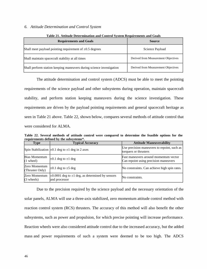
46
6. Attitude Determination and Control System
Table 21. Attitude Determination and Control System Requirements and Goals
Requirements and Goals Source
Shall meet payload pointing requirement of ±0.5 degrees
Science Payload
Shall maintain spacecraft stability at all times
Derived from Measurement Objectives
Shall perform station keeping maneuvers during science investigation
Derived from Measurement Objectives
The attitude determination and control system (ADCS) must be able to meet the pointing
requirements of the science payload and other subsystems during operation, maintain spacecraft
stability, and perform station keeping maneuvers during the science investigation. These
requirements are driven by the payload pointing requirements and general spacecraft heritage as
seen in Table 21 above. Table 22, shown below, compares several methods of attitude control that
were considered for ALMA.
Table 22. Several methods of attitude control were compared to determine the feasible options for the requirements defined by the subsystems48.
Type Typical Accuracy Attitude Maneuverability
Spin Stabilization
±0.1 deg to ±1 deg in 2 axes Use precision maneuvers to repoint, such as
torquers or thrusters
Bias Momentum (1 wheel)
±0.1 deg to ±1 deg Fast maneuvers around momentum vector Can repoint using precision maneuvers
Zero Momentum
(Thruster Only)
±0.1 deg to ±5 deg
No constraints. Can achieve high spin rates.
Zero Momentum
(3 wheels)
±0.0001 deg to ±1 deg, as determined by sensors
and processor
No constraints.
Due to the precision required by the science payload and the necessary orientation of the
solar panels, ALMA will use a three-axis stabilized, zero momentum attitude control method with
reaction control system (RCS) thrusters. The accuracy of this method will also benefit the other
subsystems, such as power and propulsion, for which precise pointing will increase performance.
Reaction wheels were also considered attitude control due to the increased accuracy, but the added
mass and power requirements of such a system were deemed to be too high. The ADCS

47
instruments that will be implemented are outlined below in Table 23. All of the components shown
below have proven flight heritage on similar mission types.
Table 23. The following instruments of attitude determination and control will meet the pointing requirements of all other subsystems and help ensure mission success.
Function
Component
Use
Quantity
Attitude Determination
Sun Sensors
Determine orientation based on position of Sun
4
Star Tracker Uses relative positions of specific stars to
determine attitude and position of spacecraft
2
Framing Camera Visually determines spacecraft position and orientation compared to object in view
1
Radar Altimeter Determines distance between spacecraft an asteroid
1
IMU Measures acceleration and angular rate of spacecraft
1
Attitude Control
RCS Thrusters
Provides directional thrust to change attitude
12
Star trackers will be the primary instruments used to determine the orientation and position
of ALMA, as well as when to initiate orbital maneuvers. ALMA uses two star trackers so that the
maximum possible accuracy is achieved on all three axes. The accuracy of the star trackers
combined with the redundancy of the sun sensors makes using both an attractive option. Sun
sensors will be used to ensure proper orientation during transit and while on-station. They are
lightweight, low-cost, and provide redundancy to the star trackers. The ALMA Framing Camera
will be used to obtain visual confirmation of 2008 EV5, which will assist in attitude determination
and control during target approach and the science investigation. A radar altimeter will assist in
maintaining the correct distance between the asteroid and spacecraft. The inertial measurement
unit (IMU) will determine when the main engine and RCS thrusters have been fired for enough
time, as well as how much the spacecraft has rotated in this time. RCS thrusters will be the sole
method of active attitude control; they will be used to achieve stability after launch, as well as for
maintaining stability during transit. During the science investigation, the thrusters will be used for

48
repositioning and other station keeping so that all necessary data is collected. Four 20 N thrusters
will be available for large repositioning maneuvers and eight 1 N thrusters will be used for small
maneuvers, but all RCS thrusters will be utilized for basic attitude control. The planned
configuration is shown below. This configuration will provide full, 3-axis attitude control. The
possibility of thruster exhaust making contact with the antenna has been considered and the risk
will be primarily reduced by mounting the thrusters on small booms in order to extend them past
the edge of the antenna. The risk will be further reduced by shielding the antenna where necessary.
Figure 19. The two central thrusters (seen as red dots) depict the 20 N thrusters, while the red thrusters on each corner depict the 1 N thrusters. This configuration provides full three-axis control.
A malfunction of the ADCS components would lead to problems with other subsystems
due to a failure to meet pointing requirements. In order to mitigate the risk of losing attitude
control, the TRL and heritage of each part have been major factors in the selection process. Proven
heritage decreases the chance of failure when compared to a newly developed product. This will
help ensure mission success.
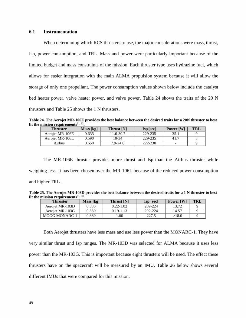
49
6.1 Instrumentation
When determining which RCS thrusters to use, the major considerations were mass, thrust,
Isp, power consumption, and TRL. Mass and power were particularly important because of the
limited budget and mass constraints of the mission. Each thruster type uses hydrazine fuel, which
allows for easier integration with the main ALMA propulsion system because it will allow the
storage of only one propellant. The power consumption values shown below include the catalyst
bed heater power, valve heater power, and valve power. Table 24 shows the traits of the 20 N
thrusters and Table 25 shows the 1 N thrusters.
Table 24. The Aerojet MR-106E provides the best balance between the desired traits for a 20N thruster to best fit the mission requirements31, 32.
Thruster Mass [kg] Thrust [N] Isp [sec] Power [W] TRL
Aerojet MR-106E 0.635 11.6-30.7 229-235 35.1 9
Aerojet MR-106L 0.590 10-34 229-235 41.7 8
Airbus 0.650 7.9-24.6 222-230 - 9
The MR-106E thruster provides more thrust and Isp than the Airbus thruster while
weighing less. It has been chosen over the MR-106L because of the reduced power consumption
and higher TRL.
Table 25. The Aerojet MR-103D provides the best balance between the desired traits for a 1 N thruster to best fit the mission requirements31, 33.
Thruster Mass [kg] Thrust [N] Isp [sec] Power [W] TRL
Aerojet MR-103D 0.330 0.22-1.02 209-224 13.72 9
Aerojet MR-103G 0.330 0.19-1.13 202-224 14.57 9
MOOG MONARC-1 0.380 1.00 227.5 >18.0 9
Both Aerojet thrusters have less mass and use less power than the MONARC-1. They have
very similar thrust and Isp ranges. The MR-103D was selected for ALMA because it uses less
power than the MR-103G. This is important because eight thrusters will be used. The effect these
thrusters have on the spacecraft will be measured by an IMU. Table 26 below shows several
different IMUs that were compared for this mission.

50
Table 26. The Northrop LN-200S is the best IMU for the mission because of its low mass and power requirements34, 35, 36.
IMU
Mass
[kg]
Power
[W]
Range
[deg/sec]
Bias
[deg/hr]
Angle Random Walk
[deg-rt-hr]
Scale Factor
[ppm]
Operating Temperature
[°C]
Northrop LN- 200S
0.748
12
1000
<0.1
<0.07
300
-54 – 71
Honeywell MIMU
4.44
22
375
<0.005
<0.005
<1
-30 – 65
Airbus ASTRIX 200
13
6.5 per ON
channel
5
<0.0005
<0.0002
30
-10 – 50
All of the IMUs considered were deemed accurate enough to achieve the science pointing
requirements, but the LN-200S has considerably less mass and a larger operating temperature
range than the other options. It also does not require as much power as the Honeywell MIMU. The
input range of the LN-200S will reduce the chance that the spacecraft will be in a situation where
the IMU cannot determine the angular rate or acceleration. The LN-200S is less accurate than the
other options, but meets the mission pointing requirements. The Northrop LN-200S is the best
choice for ALMA because of its low mass and power consumption, as well as its high input and
operating temperature ranges.
Table 27. The Sinclair ST-16RT is the best star tracker for the mission because of its low mass and power requirements37, 38, 39, 40.
Star Tracker
Mass
[kg]
Power [W]
Bore-sight accuracy
[arcsec]
Roll axis accuracy
[arcsec]
Radiation Tolerance
[krad]
Sinclair ST-16RT 0.158 1 <4 <30 9
BCT Nano Tracker 1.3 1 <6 <40 -
Surrey Procyon 1.2 6.5 <5 <30 5
Surrey Rigel-L 1.2 6.5 <3 <25 5
The Sinclair ST-16RT is the best choice for ALMA because of its low mass and power
requirements. All of the examined star trackers, shown above in Table 27, fall within the required
pointing accuracies, but the ST-16RT is the best rated with regards to radiation shielding. This will
lower the risk of failure during the mission, as well as reduce the length of time needed for

51
development and testing by the spacecraft build team. The ST-16RT is currently a TRL 8, but final
development and testing by the manufacturer will bring it up to TRL 9 before ALMA enters
development. Even if the component is TRL 8 at the time of ALMA development, the part will
still be desirable since it is based on TRL 9 technology.
Table 28. The SolarMEMS SSOC-D60 is the best sun sensor for the mission because of its proven flight heritage and wide range of operating temperatures41, 42, 43, 44, 45.
Sun Sensor
Type
Mass [kg]
Power
[W]
Accuracy
[°]
Radiation
Tolerance
[krad]
Operating Temp. [°C]
Number of Axes
TRL
SolarMEMS SSOC-D60
Digital
0.035
0.35
<0.3
30
-45 to 85
2
9
New Space Systems Fine
Sensor
Digital
0.035
0.13
<0.2
10
-25 to 50
2
9
New Space Systems
Cubesat Sun
Sensor
Analog
0.005
0.05
<0.5
-
-25 to 50
1
9
SolarMEMS nanoSSOC-
A60
Analog
0.004
0.01
<0.5
>100
-30 to 85
2
8
SolarMEMS nanoSSOC-
D60
Digital
0.007
0.115
<0.5
30
-30 to 85
2
8
The SolarMEMS SSOC-D60 is the best sun sensor for the ALMA spacecraft. Its accuracy
of 0.3 degrees will fulfill the requirements of several other subsystems, including communications
and the science payload. It has a wider range of operating temperatures than the other options,
which will reduce the strain on the thermal subsystem, as well as a higher radiation tolerance. The
SSOC-D60 has been chosen over its nano-SSOC counterparts because those versions are TRL 8,
while TRL 9 components are preferred. Using a product that already has proven flight heritage
will allow the ALMA team to save time and money on development and testing. It also eliminates
the risk related to using an unproven component. The mass and power characteristics of the sun
sensors were given less weight during the decision process because they all fell within the
allocated budgets. The decision was made to prioritize accuracy and environmental survivability,

52
such as temperature and radiation tolerance, to ensure that the sensors will be as accurate as
possible under any expected conditions.
The final ADCS component is a radar altimeter, which will be used to determine ALMA’s
distance from EV5. A Light Detection and Ranging (LIDAR) sensor was also considered for this
role, but the added cost, power, and thermal requirements were deemed to be too costly for this
mission. The key factor in determining which radar altimeter to use was the altitude range. ALMA
needs to detect when it is 1276 m away and 500 m away from the asteroid. Due to the large required
altitude range, and following the low mass and power requirements, the Honeywell HG8500 Series
Radar Altimeter was selected. The key specifications are shown below in Table 29. This particular
model will require radiation hardening, such as a conformal coating. A version of this altimeter
(HG8505DA) was used on the Pathfinder mission during the entry, descent, and landing phase 46.
This heritage further demonstrates the appropriateness of this component.
Table 29. Specifications of Honeywell HG8500 Series Radar Altimeter 47
Specification Value
Altitude Range 0 to 2.44 km
Input Power 16 W
Mass 1.36 kg
Accuracy ±(1 m + 1%)
6.2 Delta V Budget
The Δv required for sufficient ADCS design was derived from the science requirements
of the mission. For an effective science investigation, the spacecraft needs to move positions
around the asteroid so that different swaths can be examined. The distance traveled, and the
desired Δv required to do so, were the driving factors in these calculations. A low Δv was
desired to prevent adding more stress to the science instruments while they were in use, possibly
requiring recalibrations. From these driving factors, the following Δv budget was determined and
shown in Table 30.

53
Table 30. ALMA is prepared to make several maneuvers in order to support the science investigation, as well
as correct any instability during the mission. Maneuver Δv Required [m/s]
776m Altitude Change 26.71
3 90m Swath Changes 12.17
Station keeping 222.02
Total 260.9
In order to estimate how long each position change would take, and the propellant required,
the forward Euler method was used to numerically integrate the velocity and position with a Δt of
0.01 seconds. A constant force was assumed for the first half of each maneuver and then the force
direction was reversed for the second half, until the desired position change is achieved. From this,
a max velocity was found. The max velocity was doubled to obtain the total Δv for the maneuver.
The total time for each maneuver is shown below in Table 31.
Table 31. Estimated time elapsed during science maneuvers. Maneuver Elapsed Time [sec]
776m Altitude Change 115.89
90m Swath Change 177.41
7. Command and Data Handling
7.1 Architecture
All command functions and data will be handled by the on-board processing subsystem
whose design is driven by the science data needs and mission architecture requirements in Table
32. The subsystem shall handle the high payload science data collection rate that must be returned
to Earth. To maintain feasible communication downlink rates, the maps of the asteroid will be
compressed by a factor of 10 into JPEG format and fused with the spectral data for storage and
later transmission. In addition to science data processing, ALMA’s Command and Data Handling
(CDH) subsystem shall manage the spacecraft’s decisions and actions for guidance, navigation,
and control as well as any commands to the other powered subsystems to maintain spacecraft
health.

54
Table 32. Derived processing requirements for the CDH subsystem flow down from mission level
requirements and reinforce the feasibility of the data prioritizing mission.
Requirement Description Implication to On-Board Processing
Performance Process, store, and transmit 8.78 GB of
science data flowing at 2.2 Mbps High speed interfaces
Large data storage volume
Data content High resolution images and spectral data
Engineering housekeeping data
JPEG compression capability
Multiple subsystem control cards
Risk
High probability of success Autonomy must be tested and capable of
upgrades
Design Life
1 year in space environment Single string connections
Reasonable interplanetary radiation tolerance
The principal architecture trades for computation handling decided the amount of on-board
storage and processing, as well as whether a central or distributed processing topology is more
appropriate. ALMA implements a space-based data processing system with significant on-board
storage due to limited downlinking availability. A day-staff-only level of automation will ensure
all science data can be handled with high recovery percentages. The automation level concept is
defined for nominal operations to be automated with a small staff available for anomalous
situations. This high capability removes any command uplink latency issues common to
interplanetary spacecraft and minimizes ground operations equating to risk and cost reduction.
Based on the data flow in Figure 20, ALMA’s computer will prioritize processing sequencing in
the autonomous decision making process.

55
Figure 20. The ALMA data flow diagram demonstrates the efficient handling of data from the sources, where
processing occurs, and where the final data is used. The goal of the CDH subsystem is to move the needed
information from the payload to the science team with speed and at minimum cost and risk.
Figure 21. The ALMA spacecraft block diagram is based on proven remote-sensing mission design with an extremely capable CDH subsystem controlling all spacecraft functions through high speed interfaces.
Following the low cost mission architecture with moderate risk tolerance, the CDH
subsystem will utilize a centralized topology detailed in Figure 21 with a Central Electronic Unit
(CEU) handling the command routines to be executed, as well as the processing of collected data,
following the architecture of other asteroid space probes such as Dawn and Hayabusa 2. Since
56
attitude, payload, and communications functions rarely occur simultaneously in the near-asteroid
operations, the central computer can handle the functions grouped on the primary CEU computer.
The high reliability of the central architecture works well with the few powered subsystems whose
interfaces will be single string, and will focus on reliability over redundancy in order to reduce the
distributed wiring harness complexity and subsystem component cost.
7.2 Flight software
Flight software for ALMA will be common to other asteroid remote-sensing and
interplanetary observation missions in order to reduce software development and testing during
verification. ALMA’s code will distribute and manage onboard computational resources and
memory, sequence command and data flows, perform command execution validation, be able to
support three weeks of command sequences without uplink, and gather subsystem health reports.
Following heritage asteroid projects, ALMA will assume 80% of the code must be retested through
simulation to reduce risks inherent to automation code49. The considerable software development
costs were estimated from the unadjusted basic COCOMO 81 Development Effort Equation48.
Software costs are approximately $1.94M. The flight software’s many functions are evident in the
estimated source lines of code in Table 33 which has been tailored to the mission architecture.
Included in the estimated SLOC is a standard required post-launch reserve of 100% spare
capability, factored into the throughput requirement, which is used for preliminary capability
requirements.

57
Software Components SLOC comments
Executive 1000 Manages states and function group transitions
Communications 4500 Interprets commands and delivers final data
Command Processing 1000 Req.
Telemetry Processing w/ compression
3500
JPEG compression of science maps
Attitude/Orbit Sensor
Processing
1700
Handles sensor input/output and errors
Rate Gyro 800 Req.
Sun Sensor 500 Req.
Star Tracker w/out star ID 400 Req.
ADCS 21300 GNC software
Kinematic Integration 2000 gyro rate integration estimation of attitude
Kalman Filter 8000 filter applied in control loop
Error Determination 800 determine spacecraft orientation’s inaccuracy
Ephemeris Propagation 2000 minimized for short mission duration
Orbit Propagation Complex 8500 interplanetary trajectory model
Attitude Actuator Processing 900 thruster control
Fault Detection 15500 identifies on-board equipment failures
Monitor 8000 based on autonomy level
Fault Identification 2500 Req.
Fault Correction 5000 Req.
Utilities 7250 Nominal values
Basic math 800 Req.
Transcendental math 1500 Req.
Matrix math 1750 Req.
Time management 700 Req.
Coordinate Conversion 2500 Req.
Other Functions 5000 Nominal values
Momentum Management 3000 Req.
Power Management 1200 supports CDH functions
Thermal Control 800 supports CDH functions
Estimated SLOC 57150
Contingency 57150 post-launch reserve
RTOS 1000 real time operating system
TOTAL 115300
Table 33. The nominal performance SLOCs have been adjusted to improve ALMA’s reliability and ensure
the subsystem is robust to data and command faults. In particular, the communications code accounts for
telemetry compression, the ADCS accounts for the short but complex mission operations, and the fault
detection is tied to the high level of autonomy48.

58
Normalized Attribute Weights
0.07
0.64
0.28
7.3 CDH Subsystem Components
The ALMA CEU contains all of the spacecraft subsystem controllers and is capable of
autonomously commanding spacecraft functions, executing commands sent from Earth, handling
all science and engineering data, and dealing with inputs and outputs directly to other subsystems.
Figures of merit traded during selection of the primary computer included cost, reliability, and
capability. Space-qualified computers for interplanetary missions are more expensive than COTS
components used in typical LEO smallsats, must be robust to radiation exposure and single event
upsets, and must be able to perform complex command operations. An analytical hierarchal
weighting of the figures of merit accounts for the central architecture and multiple subsystem
responsibilities in Table 34.
Table 34. The analytical hierarchy process justifies the selection of a CEU compute with proven reliability based on heritage and performance success.
Note that the ALMA figure of merit priorities for the flight computer ensure the subsystem
will be robust to catastrophes regardless of the low budget. The capability requirement was derived
from the percentages of estimated SLOC for the software-driving ADCS and communications type
instructions, 37% and 8% of total SLOC respectively, and robust clock speeds for the ability to
hand shake with payload instruments. The throughput for a speed of 132 MHz requires
approximately 100 Million Instructions per Second (MIPS). From Figure 22, the RAD 750
processor can be seen to exceed this performance requirement and is a flight proven processor with
extensive reliability heritage and radiation hardening. Ideally suited to ALMA’s interplanetary
Cost Reliability Capability
Cost 1.00 0.14 0.20
Reliability 7.00 1.00 3.00
Capability 5.00 0.33 1.00

59
mission architecture requirements, this COTS processor’s non-trivial cost is mitigated due to its
flexible form factor, capability, and ease of integration.
Figure 22. The required power [W] versus the processor performance [MIPS] shows the exponential nature
space processors capability. The RAD 750 lies in the higher end of the performance, meeting the required
capabilities of the CDH subsystem, and comes in scalable 3U and 6U form factors50.
The CDH subystem minimizes development risk and nonrecurring cost through heritage
components. The payload, ADCS, communications, and CDH data processing and flight software
are run by a BAE “radiation-tolerant” RAD 750 processor. A “rad-hard” version is available but
unnecessary considering ALMA’s mission duration of one year and limited budget. ALMA’s Rad
750 is a 32-bit single board computer that will be housed in an industry standard 3U Compact PCI
(CPCI) form factor for availability, scalability, and reduced mass and complexity. The RAD 750
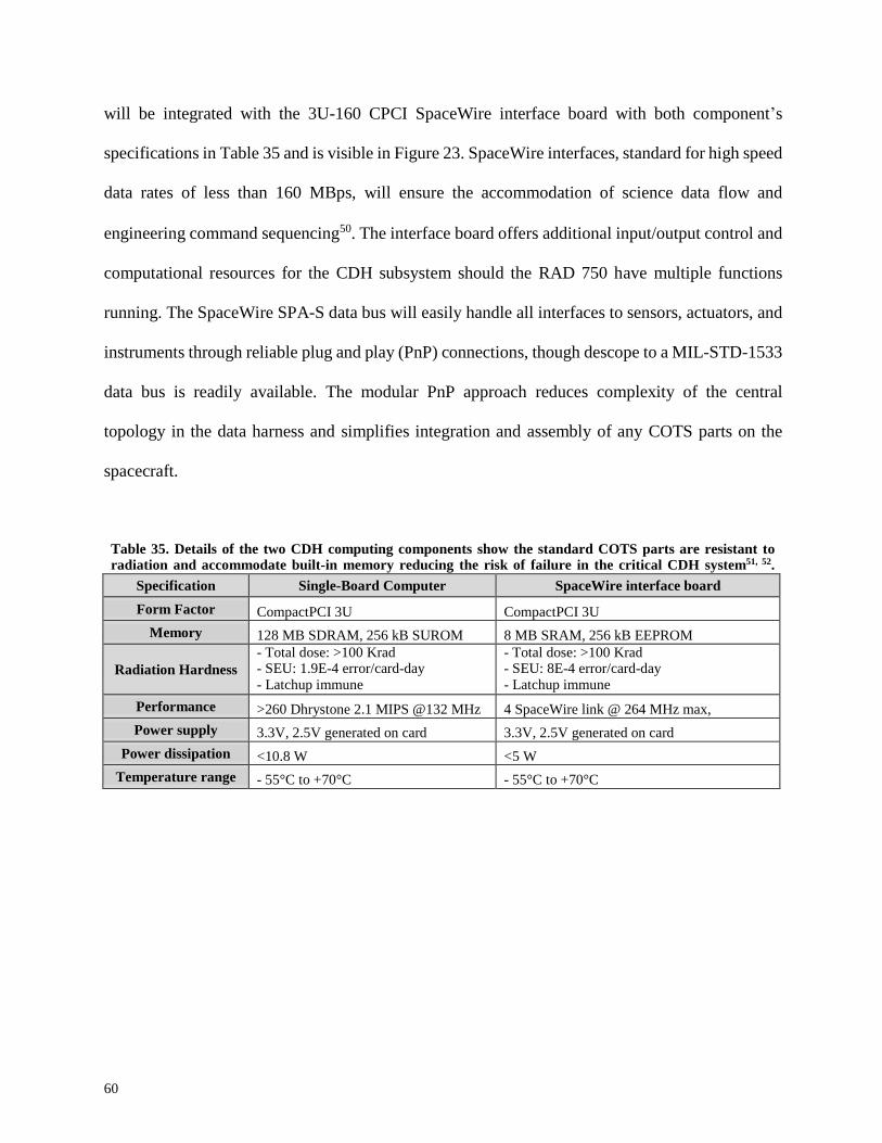
60
Specification Single-Board Computer SpaceWire interface board
Form Factor CompactPCI 3U CompactPCI 3U
Memory 128 MB SDRAM, 256 kB SUROM 8 MB SRAM, 256 kB EEPROM
Radiation Hardness
- Total dose: >100 Krad - SEU: 1.9E-4 error/card-day - Latchup immune
- Total dose: >100 Krad - SEU: 8E-4 error/card-day - Latchup immune
Performance >260 Dhrystone 2.1 MIPS @132 MHz 4 SpaceWire link @ 264 MHz max,
Power supply 3.3V, 2.5V generated on card 3.3V, 2.5V generated on card
Power dissipation <10.8 W <5 W
Temperature range - 55°C to +70°C - 55°C to +70°C
will be integrated with the 3U-160 CPCI SpaceWire interface board with both component’s
specifications in Table 35 and is visible in Figure 23. SpaceWire interfaces, standard for high speed
data rates of less than 160 MBps, will ensure the accommodation of science data flow and
engineering command sequencing50. The interface board offers additional input/output control and
computational resources for the CDH subsystem should the RAD 750 have multiple functions
running. The SpaceWire SPA-S data bus will easily handle all interfaces to sensors, actuators, and
instruments through reliable plug and play (PnP) connections, though descope to a MIL-STD-1533
data bus is readily available. The modular PnP approach reduces complexity of the central
topology in the data harness and simplifies integration and assembly of any COTS parts on the
spacecraft.
Table 35. Details of the two CDH computing components show the standard COTS parts are resistant to radiation and accommodate built-in memory reducing the risk of failure in the critical CDH system51, 52.

61
Figure 23. BAE’s RAD 750 single board computer (left) and SpaceWire interface board (right) are in a
standard 3U form factor allowing the powerful computational elements to be easily integrated on
ALMA51, 52.
CEU components including the payload, I/O, uplink/downlink, attitude, and power cards
are connected by a backplane and linked to the main processor. An additional 14.53 GB of mass
memory, besides the 136 MB of SRAM on the processor and interface board, holds a 50%
contingency on science and engineering data requirements and will be accessible by the CEU.
Consisting of cost-effective Electrically Erasable Programmable Read-Only Memory (EEPROM)
flash memory for storing the flight software, command sequences, and science data, the non-
volatile mass memory will retain data in case of a power outage during science operations.
The high reliability required of the CDH system in the central architecture is answered by
the subsystem’s components’ robustness to data volume and speed as well as the use of radiation
hardening techniques. The risk of single event upsets, the largest radiation-related danger in the
interplanetary conops, is mitigated through the heritage of the BAE electronics. An aluminum
housing structure for the electronic elements will ensure the total ionizing dose remains below 30
krads, the typical failure amount for the COTS flash memory. The SRAM and RAD 750
components have much higher radiation tolerance, minimizing radiation-related risk during the
operational lifecycle.

62
8. Telecommunications
8.1 Architecture Feasibility
As an interplanetary science mission, ALMA will communicate with Earth through the
Deep Space Network and follow the Consultative Committee for Space Data Systems (CCSDS)
recommendations on telemetry delivery for a communications architecture robust to data loss. A
store and forward approach for science data return will be used, with ALMA transmitting one hour
per week to the DSN. Science data volume and the contact availability set the subsystem’s required
downlink data rate which was input into the link budget analysis in Table 36. ALMA supports an
X-band frequency link, which allows for data rates 13.5 times faster than S-band, to be
compatible with the DSN and was chosen to accommodate downlink data rates over the worst
case distance of one AU. ALMA will link to the 34-meter Beam Wave Guide (BWG) ground
station antennas because of their proven capabilities, lower operations cost, and higher
availability compared to other DSN antennas. All uplink commands and downlink science data,
telemetry, and tracking will be passed through these DSN antennas, so ALMA requires a high gain
system of reliable components designed for maximum data delivery to the 34-meter BWG.
Specifications of the telemetry, tracking, and command subsystem were iterated through the link
analysis to achieve a required link margin of 5 dB with spacecraft antenna size, RF power, and
data rate being the primary design parameters.

63
X-Band Uplink X-Band Downlink Comments
Max link distance [AU] 1 1 worst case orbital distance
Signal frequency [GHz] 7.2 8.45 X-band DSN allocations
Data rate [kbps]
10
375 Uplink: minimal standard
Downlink: design constraint
Transmit DSN BWG Antennas Spacecraft HGA
Antenna Diameter [m] 34.00 2.00 design parameter
Pointing Accuracy [°] n/a 0.30 ADCS capability
Antenna beamwidth [°] n/a 1.24 θ = 21 / (freq(Ghz) * D(m))
Power [W] 20000.00 80.00 power budget constraint
Antenna gain [dB] 68.30 43.41 G = η *π^2*D^2/λ^2
Antenna efficiency n/a 0.70 assumed
Line loses [dB] -11.81 -2.00 assumed
EIRP [dBW] 99.50 60.44 EIRP=Pt*Gt*Lt
Losses DSN BWG Antennas Spacecraft HGA
Pointing [dB] -3.00 -0.70 Lθ = -12(offset/bandwidth)^2
Space [dB] -279.11 -274.48 Ls = (λ /(4* π *d)^2
Atm. Attenuation [dB] -0.20 -0.40 assume 90% availability
Implementation [dB] -2.00 -1.00 assume
Total Loss [dB] -284.31 -278.58
Receive Spacecraft HGA DSN BWG Antennas
Antenna diameter, m 2.00 34.00
Antenna efficiency 0.60 n/a Assumed
G/T, dB/K n/a 53.90 Given Smad
Line losses [dB] -2.00 n/a Assumed
Antenna gain [dB] 42.02 78.52 G/T = Gr-T
Power, dB -142.79 -133.51 Pr = Pt*Gt*Gr*Ls
Energy per bit dB -182.79 -191.35 Eb = Pr(W) / R(b/s)
System noise temp, K 50.00 290.00 DSN link handbook
Noise density dB -211.61 -203.98 No = K*Ts
Received Eb/N0 [dB] 28.82 12.62
Required Eb/N0 [dB]] 10.00 7.60 QPSK modulation
Link margin [dB] 18.82 5.02 5 dB downlink requirement
Table 36. Figures of merit used in preliminary subsystem design are bolded in the downlink analysis and
highlight the robustness of the telecommunications link for high-speed data rates and strong tracking
abilities.

64
The link analysis shows ALMA’s prioritization for payload data delivery, but the
Telemetry, Tracking, and Commanding (TTC) system will also provide highly accurate ranging
information and general engineering data for the operations team on the ground. Minimal radio
signals will be sent during the Hohmann transfer; likely, monthly uplinks and checkouts with
Doppler tracking will verify the orbital trajectory in order to reduce the DSN costs. Budgeting for
the use of the BWG antennas was done using the DSN hourly Aperture Fee (AF) equation and
determining the amount of time necessary for data transmission48. At an AF of $1,144.23 per hour,
ALMA will require just over $22K for TTC, radio science, and engineering support services53.
8.2 Functions and Components
The telecommunications subsystem parts were chosen for reliability and mission heritage
to meet the functional requirements of deep space communications, ranging navigation, and
gravimetric science. Comprised of largely government-off-the-shelf (GOTS) components, this
critical subsystem has low technical and cost risk. To achieve the considerable downlink rate of
375 kbps determined by science conops, a High-Gain Antenna (HGA) was sized to two meters in
diameter. Despite being the largest part on the spacecraft bus and needing to be custom
manufactured, the non-gimbaled parabolic reflector antenna has high technology readiness and
scalability. Since ALMA can achieve a high pointing accuracy, and does not require data collection
during downlink, the HGA can be fixed to the spacecraft bus to reduce mechanical complexity. A
redundant patch antenna, mounted opposite of the HGA for increased communications coverage,
shall also receive the uplink commands at a standard rate of 10 kbps and reduce link loss risk for
minimal cost.

65
The primary components of the communications system, however, are the Small Deep
Space Transponder (SDST) and Traveling Wave Tube Amplifier (TWTA). The SDST is the
interface between the telecommunications and CDH subsystems and creates the signals carrying
the science and housekeeping data to be sent to Earth. As the typical transponder for interplanetary
space missions, the SDST incorporates the technical capabilities of the Cassini Deep Space
Transponder with 70% fewer parts, 60% less mass, and 45% less cost. It has mission heritage from
Deep Space 1, the Mars rovers, Dawn, and many other missions50. The TWTA with an electronic
power conditioner amplifies the signals given by the SDST to the required radio frequency output
power of 80 W, a capability beyond the solid-state power amplifiers (SSPA) commonly found in
near earth missions. All signals handled by the telecommunications subsystem pass through the
common diplexer which isolates transmit and receive paths as depicted in Figure 24.
Figure 24. The communications subsystem block diagram shows ALMA minimizes the number of components for reduced complexity and mass while selecting high-quality parts to make sure the science architecture is robust to link loss54.

66
8.3 Safe Mode Communications
ALMA’s communications link design approach targets the risk of science data loss. Since
telecommunications link loss is a risk factor for any deep space mission, ALMA will implement a
safe mode during anomalous operations to reestablish a connection with Earth. A minimal uplink
and downlink rate of 10 bps requiring 1 W of power will allow either the high or low gain antennas
to achieve connection with Earth since the CDH will direct the ADCS to orient the spacecraft to
achieve nominal attitudes. ALMA’s autonomous functions shall maintain the safe mode operations
in the near-asteroid station until the next available DSN coverage opportunity to ensure spacecraft
tracking recapture.
9. Thermal
9.1 Constraints and Requirements
The primary objective of the thermal control system is to establish and maintain a suitable
thermal environment for the spacecraft bus and payload. The largest factors driving the design of
the thermal control system are the thermal requirements of the science payload and the components
that comprise the subsystems. Constraints derived from the spacecraft layout and management
plan also impact the thermal control system design. The ALMA thermal control system
requirements can be seen in Table 37.
Table 37. ALMA thermal control system requirements and goals, which were derived from physical
constraints and flowed down from requirements set for the science payload and subsystem components.
Requirements and Goals Source Type
Shall ensure the science payload maintains allowable temperature Flow-down, Payload Functional
Shall ensure the sub-system components stay within allowable operating and storage temperature ranges
Flow-down, Subsystems
Functional
Shall ensure that the thermal control system can be designed, tested, and
integrated within the allotted cost
Allocation, Cost
Breakdown
Constraint
Shall stay within the volumetric constraint defined by the launch vehicle
payload fairing dimensions
Derived, Launch Vehicle
Constraint

67
In order for ALMA to stay fully functional throughout the entirety of the mission, the
components onboard must stay within operational and storage temperature ranges. The operational
and storage temperature ranges are defined by the specifications of the particular components that
have been selected. Operational and storage temperature requirements were compiled from the
specifications of the components and can be seen in Table 38.
Table 38. Science payload and subsystem component storage and operational temperature requirements, which were derived from the specifications of particular components and must be met for proper operation
Subsystem Component Storage Temperature [ºC] Operational Temperature [ºC]
Science
Framing Camera -20 to 60 -10 to 50
GRS -34 to 65 -20 to 35
Power
Batteries 10 to 25 10 to 25
Solar Cells -200 to 130 -150 to 110
Attitude,
Determination,
and Control
IMU -62 to 85 -54 to 71
Star Tracker -10 to 40 0 to 30
Propulsion Hydrazine Tank and Lines 5 to 50 15 to 40
Communications
Antennas -120 to 120 -100 to 100
Antenna Gimbals -50 to 90 -40 to 80
9.2 Thermal Control Architecture
Thermal control of a spacecraft can be done with a number of different common methods,
and the ultimate design depends on requirements of the system. In order to meet the requirements
outlined above, many different thermal control components and architectures were analyzed, and
the different options can be seen in Table 39.

68
Table 39. Detailed breakdown of the thermal control architecture and components options that were analyzed in order to select the optimum system in terms of mass, power and configuration48.
Function Component Type Description
Temperature Determination
Solid State Controllers
Active Calculates and relays the temperature of a specific area
Interaction with
External Environment
Multi-Layer Insulation (MLI)
Passive Reduce the amount of heat exchange
via thermal radiation
Coatings
Passive Control emissivity of the spacecraft
exterior
Louvers
Active Control amount of thermal heat exchange with environment
Heat Provision
Electric Heaters
Active Provides heat by turning electricity
into thermal energy
Radio-isotope heaters Passive Provides heat via radioactive decay
Heat Storage
Phase Changing Material
Active Allow for storage of energy via phase change
Heat Collection and Transportation
Conductive Plates
Active Allows energy to dissipate through a
plate structure
Heat Pipes
Passive Transfers energy around the
spacecraft via piping
Cooling loops
Active Transfer energy to a dissipation unit via refrigeration loops
Thermal Joints
Passive Transfer energy from a fixed element
to a moving element
Heat Rejection
Radiators
Passive Transfer energy to the surrounding environment
Thermo-Electric Heat Pumps
Active Transfer energy to the environment at
a controlled rate
There are many key functions in the process of thermal control of a spacecraft in
interplanetary space. The main phases of thermal control on ALMA will be temperature
determination, interaction with the external environment, heat provision, heat transportation, and
heat rejection. In order to perform the different phases of thermal control, a number of different
devices are commonly used, which all have different power, mass, and TRL. In order to choose
the optimum components for ALMA, driving parameters had to be defined.
The driving parameters that were deemed a priority for the design of the thermal control
system are minimal power consumption, technology development, and mass. By placing
priority on these parameters, a baseline thermal control architecture was established and can

69
be seen in Table 40.
Table 40. The baseline thermal control system architecture designed to meet the thermal requirements and
ensure the components on ALMA stay within an allowable temperature range.
Component Type Use Quantity Total Power [W] Total Mass [Kg] TRL
Solid State Controller
Active Determine temperature across the spacecraft
5
1
0.15
7
MLI
Passive
Reduce the amount of heat
exchanged via thermal
radiation
6.5 m2
-
1.2
9
Coatings Passive Reflect Solar Radiation 3.37 m2 - - 9
Electric Heaters
Active
Provide heat to the propellant
4
40
0.4
9
Heat Pipes
Passive Moves energy via piping structure
2 m
-
0.5
6
Radiators
Passive Transfers heat to surrounding
environment
1
-
0.287
6
Five solid state controllers will be placed on ALMA at various locations including near the
science payload and propellant tanks. These solid state controllers will ensure accurate temperature
readings at critical locations. If the temperature is not within the required range, the appropriate
thermal control components will be activated.
The ALMA spacecraft will utilize multi-layer insulation (MLI) in order to reflect a large
amount of solar energy and reduce the amount of energy radiated. A two sided aluminum coated
polyimide with acrylic overcoat MLI will be utilized on ALMA because of its relatively low
emittance and solar absorbance properties, 0.04 and 0.14 respectively. The aluminum coating will
reflect a large amount of energy from the sun and the acrylic overcoat will protect the spacecraft
from humidity on Earth before launch. The MLI will have a total thickness of 0.005 mm, and will
be utilized on the five faces of the spacecraft bus that do not have the antenna, for a total of 6.5 m2
(Ref. 55). Thermal coatings will be applied to the areas on ALMA that are not already covered in
MLI. These thermal coatings will ensure that a specified level of absorbance and emittance on
those faces. The two primary components that will have thermal coatings applied to them are the
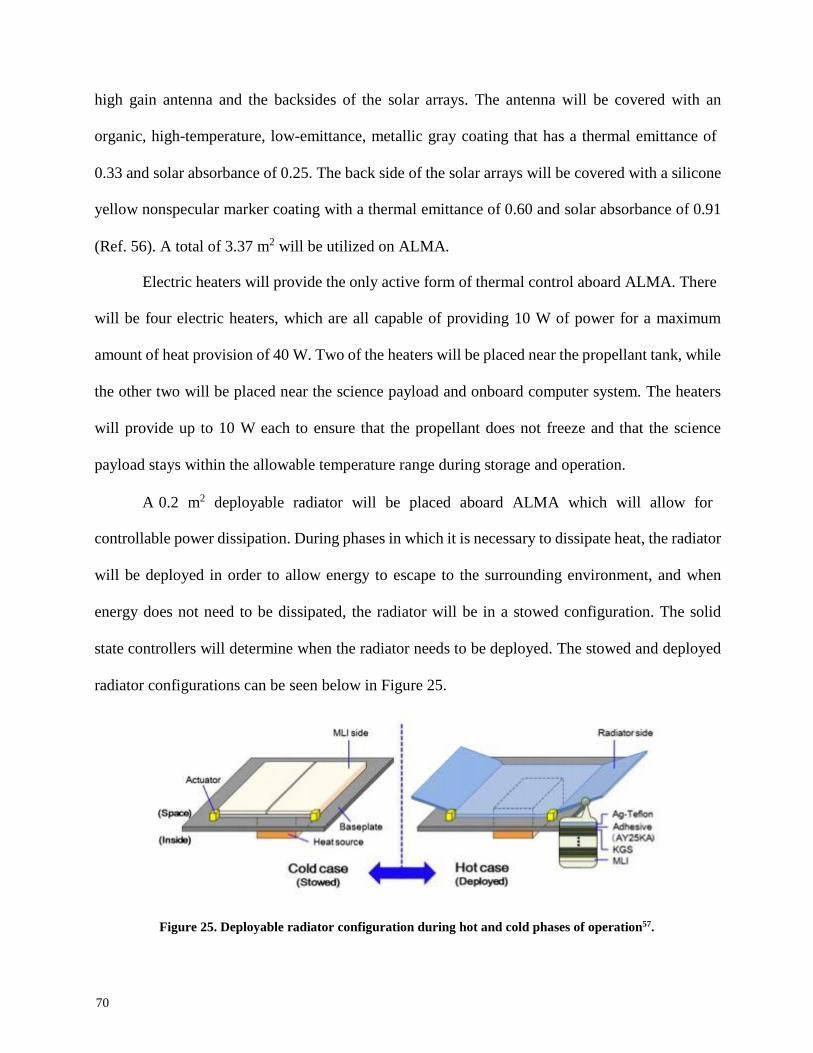
70
high gain antenna and the backsides of the solar arrays. The antenna will be covered with an
organic, high-temperature, low-emittance, metallic gray coating that has a thermal emittance of
0.33 and solar absorbance of 0.25. The back side of the solar arrays will be covered with a silicone
yellow nonspecular marker coating with a thermal emittance of 0.60 and solar absorbance of 0.91
(Ref. 56). A total of 3.37 m2 will be utilized on ALMA.
Electric heaters will provide the only active form of thermal control aboard ALMA. There
will be four electric heaters, which are all capable of providing 10 W of power for a maximum
amount of heat provision of 40 W. Two of the heaters will be placed near the propellant tank, while
the other two will be placed near the science payload and onboard computer system. The heaters
will provide up to 10 W each to ensure that the propellant does not freeze and that the science
payload stays within the allowable temperature range during storage and operation.
A 0.2 m2 deployable radiator will be placed aboard ALMA which will allow for
controllable power dissipation. During phases in which it is necessary to dissipate heat, the radiator
will be deployed in order to allow energy to escape to the surrounding environment, and when
energy does not need to be dissipated, the radiator will be in a stowed configuration. The solid
state controllers will determine when the radiator needs to be deployed. The stowed and deployed
radiator configurations can be seen below in Figure 25.
Figure 25. Deployable radiator configuration during hot and cold phases of operation57.

71
A heat pipe structure will be used to transport energy from different components and areas
to the deployable radiator. The heat pipes will be made up of thin walled, lightweight metal pipes
with liquid inside. The liquid will turn into vapor and transfer energy to the colder section of the
heat pipe. This energy can be used to heat components or be dissipated by the radiator.
Approximately 2 m of heat pipe structure will be used to transfer energy throughout the ALMA
bus.
9.3 Steady State Temperature Properties
From the thermal requirement ranges provided for each subsystem component, it can be
seen that the constraining requirement range is between 10 ºC and 25 ºC. By utilizing the baseline
thermal control architecture outlined above, a steady state temperature that falls within this range
will be reached. An analysis was performed for the worst case, “cold case,” and best case, “warm
case,” scenarios, which correspond to a distance from the sun of 0.989 AU and 1.030 AU,
respectively. These distances are the minimum and maximum distance the spacecraft will be from
the sun at any given time during the mission.
The two separate cases were evaluated for each mode of operation that ALMA will be in
throughout the duration of the mission. The steady state temperature of the spacecraft depends
upon the mode of operation due to the difference in power requirements for each of the modes. It
is assumed that 80% of the electric energy consumed will be converted into heat, which will
contribute to the thermal balance. The steady state temperature can be adjusted by dissipating or
providing heat.
The radiator will be used to control heat dissipation by either being stowed to slow thermal
radiation, or being deployed to aid thermal radiation. The electric heaters provide heat by
converting electrical power. By tuning these components for each mode of operation, the

72
spacecraft will reach a steady state temperature inside the required range. The steady state
temperature values corresponding to each mode of operation can be seen in Table 41.
Table 41. Steady state temperature of the spacecraft bus for each mode of operation, which is actively
controlled by changing the radiator status, stowed (S) or deployed (D), and adding heat via power.
Spacecraft Bus Temperature - Cold Case (1.03 AU)
TLI,
Eclipse
TLI,
Day
Burn
Cruise
Cruise,
Charging
Asteroid
Approach
Science
Downlink
Eclipse
Deployment
Radiator
Status
S
S
D
S
S
D
S
D
S
S
Power Addition [W]
40
-
-
-
20
-
-
-
40
-
Steady State Temp [ºC]
20.57
20.88
15.95
17.42
19.32
15.95
18.63
22.02
20.57
17.53
Spacecraft Bus Temperature - Hot Case (0.989 AU)
TLI,
Eclipse
TLI,
Day
Burn
Cruise
Cruise,
Charging
Asteroid
Approach
Science
Downlink
Eclipse
Deployment
Radiator
Status
S
S
D
S
S
D
S
D
S
S
Power
Addition [W]
40
-
-
-
20
-
-
-
40
-
Steady State Temp [ºC]
24.11
24.41
18.98
21.08
22.91
18.98
22.24
24.75
24.11
21.19
As can be seen in the table above, the temperature of the spacecraft bus will never go below
the lower limit of 10 ºC and never goes above the upper limit of 25 ºC. The steady state
temperatures are always within the required range, no matter the distance from the sun. An analysis
of steady state temperature versus distance from the sun was conducted and can be seen in in
Figure 26.

73
Figure 26. Steady state temperature of ALMA as a function of distance from the sun for every mode of operation, which shows that the spacecraft is always within the required thermal range. Generated using MATLAB.
The ALMA bus was analyzed separately from the solar arrays because they will not
transfer a large amount of energy to the spacecraft bus. In order to maximize the performance of
the solar arrays, the temperature of the arrays needs to stay as low as possible. In order to control
the temperature of the solar arrays, a thermal coating will be applied to the backside of each array,
which has an absorbance of 0.60 and an emittance of 0.91. By applying this coating, the arrays
will radiate a large amount of energy, which will lead to a steady state temperature of 60.9 ºC when
ALMA is closest to the sun, and a steady state temperature of 54.2 ºC when ALMA is farthest
from the sun.

74
10. Power
The power system will support the payload and the other subsystems as they accomplish their
goals. The main requirement of the power subsystem is to provide up to 205 W peak power. The
power system has been designed to utilize inexpensive and proven technology to provide the
electrical power needed for the payload and other subsystems in order to operate at a minimum
cost and risk. Additionally, the power system must stay within the cost, mass, and volumetric
constraints defined by the overall mission plan.
Several architectures were initially analyzed to determine the best way to power ALMA,
but in the end solar electric power was the only feasible way to provide enough power at low cost
and mass. Solar power has the most heritage of any power architecture, therefore the hardware for
solar electric power is also widely available.
Table 42. Solar electric power will be capable of supporting the ALMA spacecraft as it performs its mission.
Architecture Option
Advantages
Disadvantages
Solar Electric
Extensive heritage
Widely available
Inexpensive
Near constant power for long durations
Dependent on spacecraft attitude
Must remain in the inner solar system
While it is true that the power output of the solar arrays is dependent upon the spacecraft
orientation, and the spacecraft must be in the inner solar system in order to produce enough power,
these disadvantages are not expected to be issues. ALMA will stay within 1.05 AU of the Sun at
all times, and the pointing tolerances of the solar panels are well within the ADCS system’s
capabilities.

75
Table 43. Hardware options for the solar cells capable of providing ALMA enough power during sunlight
Hardware Options Advantages Disadvantages
Solar Cell
Si More efficient
Inexpensive
Less radiation tolerant
GaAs More radiation tolerant More Expensive
There are several materials that can be used to make the solar cells. Of these materials,
silicon and single junction gallium arsenide (SL GaAs) have the most heritage, and their relevant
properties are detailed in Table 15. Newer options, such as multi junction GaAs and gallium
indium solar cells are too immature to be considered for ALMA. According to SMAD, SL GaAs
solar cells are more radiation tolerant than Si cells, lasting 6 years in a high energy particle
radiation environment before losing 15% of their beginning of life (BOL) output compared to just
4 years for Si cells. Since Si is more mature than GaAs, Si has a higher achieved production
efficiency and a lower cost than GaAs48. These differences are detailed in Table 44. Therefore,
because Si solar cells are more efficient, more available, and less expensive, ALMA will utilize
Si solar cells.
Table 44. Hardware options for the solar cells capable of providing ALMA enough power during sunlight
Hardware
Options
Production Efficiency Cost per Watt
[W-1] Time to 15% Degradation in GEO
10MeV electrons
Solar Cell
Si 22% $378 4 yr
GaAs 18.5% $852 6 yr
The solar panels will need to be stowed for integration and launch. The arms on which the
solar panels are fixed will be folded to rest alongside the main spacecraft bus while in the launch
configuration. Once the ALMA spacecraft separates from the launch vehicle, the arms will fold
out and the solar panels will be oriented towards the Sun so they can begin powering the spacecraft.

76
Secondary batteries will power the ALMA spacecraft during solar panel deployment, as well as
during any unexpected loss of power from the solar panels.
The secondary batteries most often used in space applications are nickel cadmium (NiCd),
nickel metal hydride (NiH2), and lithium ion (Li Ion). To stay within the mission constraints, the
secondary batteries must be inexpensive and have a high energy density. This means that while
NiCd has a wider range of operating temperatures, and both NiCd and NiH2 have a longer history
and more lifetime charge/discharge cycles, ALMA will use Li Ion batteries since they provide the
highest available energy density at the lowest cost, as detailed in Table 45. While Li Ion is a much
newer technology, it is still a TRL 9 component, and since ALMA is not expected to go through
many eclipses, the number of lifetime charge/discharge cycles is not of high concern to ALMA.
Table 45. The advantages and disadvantages of different secondary battery options show that Li Ion batteries
are the superior choice over the more mature technologies.
Hardware Options
Advantages
Disadvantages
Secondary
Batteries
Li Ion
High Energy Density
Fewer Charge/Discharge Cycles
NiCd
Most Mature Technology
Most Charge/Discharge Cycles
Widest Operating Temperature
Lower Energy Density
Charge Memory
NiH2 Mature Technology
More Charge/Discharge Cycles
Small Operating Temperature
Lower Energy Density
Below in Table 46 is ALMA’s overall power budget. ALMA will require different amounts
of power depending on the mission phase. ALMA’s solar arrays are sized to provide 15% more
power than each subsystem’s current best power estimate. This acts as a conservative contingency
for TRL 9 technologies. The most power intensive modes are main engine burns, asteroid
approach, and downlink to the ground station. The largest amount of power consumed at any one
time by one subsystem is 135 W, which is consumed by the communications system during
downlink. While not in direct sunlight, ALMA will switch to a low-power mode, during which

77
102 W will be consumed by the spacecraft. Although ALMA is not designed to be in an eclipse of
the asteroid, the secondary batteries will be sized to power ALMA for two hours at 80% depth of
discharge using this low-power mode. This provides plenty of time for ALMA to autonomously
recognize the problem and escape the eclipse. ALMA is not expected to be in eclipse at any other
time when it is not connected to the launch vehicle.
Table 46. ALMA’s power consumption broken down by operational mode shows the efficient use of subsystem power. Primary mission modes are bolded.
Power
Thermal
Comms
Science
ADCS
Prop
C&DH
Structure Charge Battery
Total
TLI Eclipse
5.1 40.0 - - 20.1 1.5 35.0 - - 101.7
TLI
Daylight
7.7
-
32.0
-
20.1
1.5
35.0
-
16.9
111.1
Burn 10.4 - 32.0 - 41.1 50.0 35.0 - - 166.4
Cruise 6.7 - 32.0 - 21.1 - 35.0 - - 92.7
Cruise (Charge)
6.0
20.0
-
-
21.1
1.5
35.0
-
16.9
99.5
Asteroid Approach
10.4
-
32.0
-
41.1
50.0
35.0
-
-
166.4
Science 7.1 - - 38.5 36.1 1.5 35.0 - - 167.0
Downlink
12.2
-
135.0
-
21.1
1.5
35.0
-
-
202.7
Asteroid
Eclipse
5.1
40.0
-
-
20.1
1.5
35.0
-
-
101.7
Launch Vehicle
Separation
6.8
-
32.0
-
20.1
-
35.0
3.0
-
94.8
ALMA will have the capability to produce more power than is need for most of the mission
phases. Any unused energy must be dissipated as heat by the thermal control system. To reduce
stress on the thermal control system, the solar panels will be angled away from the Sun when the
spacecraft is not in downlink. The increased incidence angle will reduce the power produced by
solar panels, reducing the amount of unused energy that will need to be rejected as heat. This has
the added benefit of reducing the steady state temperature of the solar panels, because there is a

78
Solar Array
Mass [kg] Battery Mass
[kg] DET Control
Mass [kg] PDS Mass
[kg] Total Mass
[kg] Cost
[$M FY16]
4.0 2.0 0.4 1.5 7.6 4.14
smaller projected area receiving thermal energy from the Sun. This reduction in temperature
increases the overall efficiency of the solar cells.
ALMA will utilize a regulated direct energy transfer (R-DET) power control system. R-
DET provides an efficient power regulation in terms of power needed, required mass, and total
complexity. The major drawback of R-DET is that the full power generated by the solar arrays is
not available until the batteries are fully charged. However, the batteries are expected to be fully
charged at all times, so this is not an issue for ALMA.
The power control system will ensure the bus voltage remains at a constant 28 V. This is a
standard spacecraft bus voltage, allowing the ALMA team to easily find parts that can handle this
voltage. Any components that are not designed for 28 V will have their own power converter to
ensure they are not overdriven.
ALMA’s power system is expected to cost $4.14M FY16, estimated using the 2010 Small
Spacecraft Costing Model. The masses of the Si solar arrays, Li Ion secondary batteries, R-DET
power control system, and the harness of the power distribution system are detailed in Table 47
below.
Table 47. ALMA’s power system meets the power needs of the other subsystems at a minimum
cost and mass.
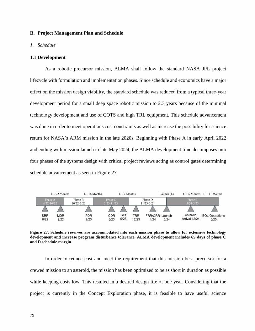
79
B. Project Management Plan and Schedule
1. Schedule
1.1 Development
As a robotic precursor mission, ALMA shall follow the standard NASA JPL project
lifecycle with formulation and implementation phases. Since schedule and economics have a major
effect on the mission design viability, the standard schedule was reduced from a typical three-year
development period for a small deep space robotic mission to 2.3 years because of the minimal
technology development and use of COTS and high TRL equipment. This schedule advancement
was done in order to meet operations cost constraints as well as increase the possibility for science
return for NASA’s ARM mission in the late 2020s. Beginning with Phase A in early April 2022
and ending with mission launch in late May 2024, the ALMA development time decomposes into
four phases of the systems design with critical project reviews acting as control gates determining
schedule advancement as seen in Figure 27.
Figure 27. Schedule reserves are accommodated into each mission phase to allow for extensive technology
development and increase program disturbance tolerance. ALMA development includes 65 days of phase C
and D schedule margin.
In order to reduce cost and meet the requirement that this mission be a precursor for a
crewed mission to an asteroid, the mission has been optimized to be as short in duration as possible
while keeping costs low. This resulted in a desired design life of one year. Considering that the
project is currently in the Concept Exploration phase, it is feasible to have useful science
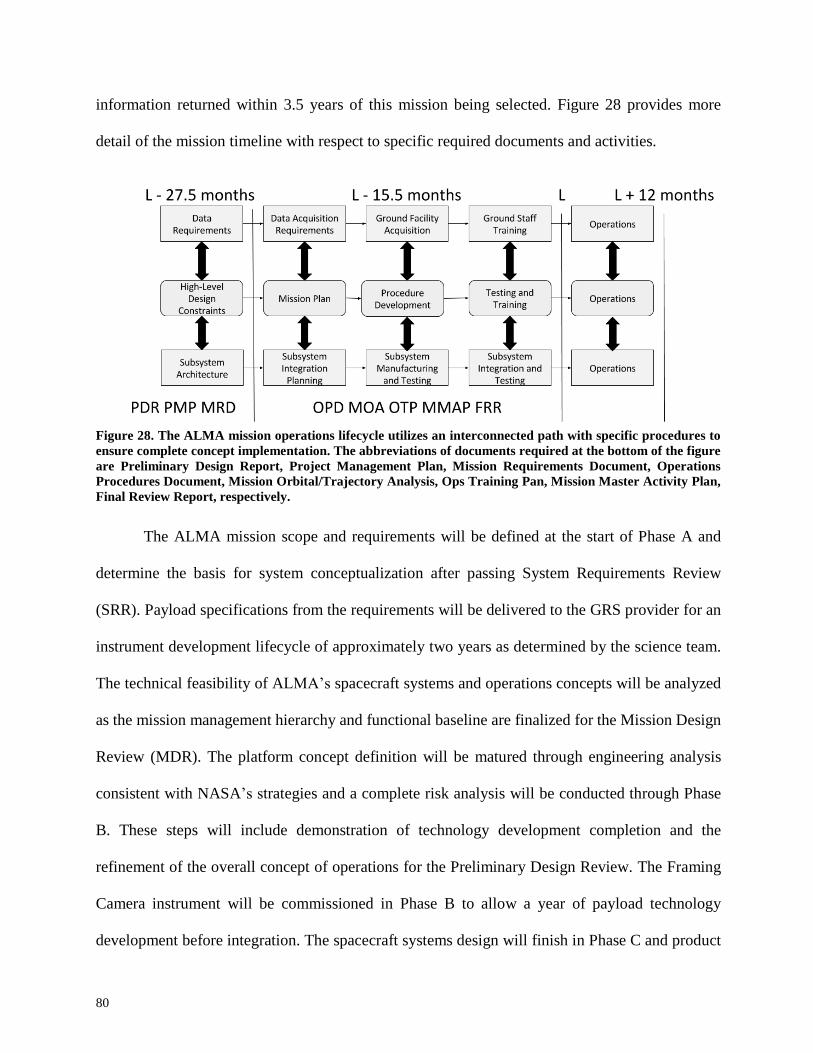
80
information returned within 3.5 years of this mission being selected. Figure 28 provides more
detail of the mission timeline with respect to specific required documents and activities.
Figure 28. The ALMA mission operations lifecycle utilizes an interconnected path with specific procedures to
ensure complete concept implementation. The abbreviations of documents required at the bottom of the figure
are Preliminary Design Report, Project Management Plan, Mission Requirements Document, Operations
Procedures Document, Mission Orbital/Trajectory Analysis, Ops Training Pan, Mission Master Activity Plan,
Final Review Report, respectively.
The ALMA mission scope and requirements will be defined at the start of Phase A and
determine the basis for system conceptualization after passing System Requirements Review
(SRR). Payload specifications from the requirements will be delivered to the GRS provider for an
instrument development lifecycle of approximately two years as determined by the science team.
The technical feasibility of ALMA’s spacecraft systems and operations concepts will be analyzed
as the mission management hierarchy and functional baseline are finalized for the Mission Design
Review (MDR). The platform concept definition will be matured through engineering analysis
consistent with NASA’s strategies and a complete risk analysis will be conducted through Phase
B. These steps will include demonstration of technology development completion and the
refinement of the overall concept of operations for the Preliminary Design Review. The Framing
Camera instrument will be commissioned in Phase B to allow a year of payload technology
development before integration. The spacecraft systems design will finish in Phase C and product

81
fabrications will begin in this first implementation phase after the Critical Design Review (CDR).
Development will move into product assembly after the System Integration Review is passed for
schedule progression into Phase D. Subsystems will be thoroughly tested for verification and
validation to meet the Flight Readiness Review before ALMA must be delivered for launch.
The development lifecycle includes a standard 5 days per month of funded schedule margin
for each phase to ensure the mission is robust to schedule setbacks. The risk of delays is inherent
in mission management architectures prioritizing high-speed, cost-effective design, but the
reduction in recurring development costs such as salary and facilities ensure ALMA’s timeline is
economically viable. The resulting development schedule reserve of 3.83 months, including one
month directly before launch integration, mitigates the risk of spacecraft delivery failure.
1.2 Operations
ALMA’s phase E operations schedule outlines the near Earth and Lunar flyby activities,
low-activity Hohmann transfer stage, and the near-asteroid station keeping science conduction.
Following separation from the Minotaur payload fairing and solar panel deployment, ALMA will
checkout with JPL for the Post-Launch Assessment Review (PLAR). Then the spacecraft will
travel for three days on a direct transfer to the moon using only the Minotaur characteristic energy.
Critical Event Readiness Review (CERR) 1 will occur on lunar approach to ensure ALMA can
safely complete the lunar flyby and first propulsive burn into the cruise stage. ALMA’s minimal
operations cruise to 2008 EV5 takes approximately 188 days with spacecraft health checks
occurring on a monthly basis to reduce DSN availability requirements. CERR 2 will take place
before the second Hohmann transfer burn and initial asteroid surveying approach, reducing the
risk of orbital trajectory errors when inserting into asteroid station in early February 2025.

82
Near asteroid events and
EV5 Operations
Duration
149d
CERR 3 0
Map 1 and 2: HASK 20.9d
Science Objectives 1,2,3 7.45h
Downlink 20d
Map 3: LASK 42.9d
Science Objectives 3,4,5 (+15° off-nadir) 7.72h
Downlink 42d
Map 4: LASK 42.9d
Science Objectives 3,4 5 (0° off-nadir) 7.72h
Downlink 42d
Map 5: LASK 42.9d
Science Objectives 3,4,5 (-15° off-nadir) 7.72h
Downlink 42d
The final CERR 3 verifies ALMA’s station is optimal for science data collection and
downlinking before actual operations, with time lengths in Table 48, take place. In order to
accommodate the DSN coverage, ALMA must downlink the maps assuming only one hour of
antenna availability per week. Therefore, most of the time spent in asteroid station will be a
downlink standby phase for data delivery opportunities. The data will be taken in an initial high-
altitude map and three subsequent maps at a lower altitude for a complete characterization of the
asteroid within 5.3 months of arrival. ALMA’s expected end of life occurs in September 2025 for
a total operations lifecycle of 352 days in space. The single string design of ALMA’s components
increases risk after one year, leaving approximately 5% schedule margin in the design life. At the
end of ALMA’s science investigation, if resources allow, such as propellant and money, ALMA
will image specific areas of interest on EV5 until system failure.
Table 48. The ALMA science operations deliver a large amount of usable data while keeping the mission lifecycle to a minimum simpler design implementation, development, and cost.

83
2. Management
All management decisions will be made in accordance with the mission objective of
providing valuable information to support a crewed asteroid mission. Reliability and ensuring
mission success will be the highest priority, followed closely by cost. A small, experienced team
is preferred over a large team because a small team will cost less overall and be easier to manage.
This will be possible due to the relatively short duration of the mission and the simplicity of science
and maneuvers being conducted.
While any organization with experience managing space missions will be able to handle
this relatively simple mission, ideally the mission will be managed by JPL due to its access to the
DSN and experience with interplanetary operations. This need not be a multi-institutional project;
any institution with experience overseeing space missions should be able to assemble a team with
enough experience to successfully complete this mission. A few small, dedicated teams will be in
charge of assembling and building ALMA’s subsystems. This is feasible because of the
limited development needed to design, manufacture, and integrate the parts of each subsystem.
Figure 29. The ALMA management hierarchy is designed to allow lower levels the autonomy to contribute to
the program while ensuring other system choices are not opposing each other to ensure mission success.

84
As can be seen in Figure 29, the ALMA principal investigator, who will have managers
working directly under him or her to provide clear communication, is the final authority for the
mission. However, decisions should be made at the lowest level by working within the
parameters set by margins to adhere to disciplined development guidelines and prevent adverse
effects. Due to the rigid constraints on mass and cost, great care should be taken when allowing
an increase in the allotted expenditure of either money or mass in any subsystem.
Smallsat missions typically have small teams, which can lend itself well to many of the
techniques listed in SMAD for reducing space mission cost and schedule48. The ALMA team
should be willing to explore new cost reduction programs and re-allocating resources where
possible if necessary to reduce cost. In addition, the team will be co-located to promote effective
communications and quick response times to problems. Reducing project cost should be rewarded
both at a personal and group level in whatever way deemed fit by the project managers. One
exception is that the use of TRL 9 components should be used as extensively as possible due to
the RFP preferring the use of “technologies already demonstrated on previous programs2.”
By following this plan, the ALMA management team will provide exceptional value to the
mission. As a new, relatively low-cost program, the ALMA management will be an example for
future missions by utilizing techniques that promote inventive, successful ways to keep costs low
and the timeline ahead of schedule.

85
C. Cost and Cost Estimating Methodology
The short duration nature of this mission will help to keep costs low. Table 49 below
highlights the allotted cost for each project element.
Table 49. Cost breakdown by work breakdown structure element, which leaves a large 23.6% margin.
Element Contingency
[%] Maximum Estimated Cost
[$M FY16]
Payload 10 10.29
Communications 15 5.73
Propulsion 10 6.29
ADCS 10 3.23
Thermal 8 0.57
Power 8 4.14
Structures 5 3.04
CDH 5 2.46
Launch Vehicle - 30
Operations - 15
Total - 81.36
Max Allowable - 100
Margin - 18.64
Every subsystem has a conservative maximum estimated cost, most of which are based on
the Small Spacecraft Cost Model (SSCM) developed by The Aerospace Corporation10. The
SSCM is a CER valid for small satellites which are Earth-orbiting, and is based on a study of 53
individual satellites. The SSCM estimate includes an estimate for integration and testing.
Although not an Earth-orbiting satellite, ALMA is a smallsat, and many aspects of the
subsystems will not change much from Earth-orbiting to interplanetary operations for ALMA.
This is because, while interplanetary, ALMA will never be more than 1 ± 0.1 AU from the Sun
and will not be doing anything unique to interplanetary missions such as landing or collecting
samples. The Operations element includes project management, systems engineering, and
facilities and staff.
The exceptions to ALMA’s SSCM estimates are the cost of the payload, which is based
on pricing found from vendors, the launch vehicle, which is derived from the cost of a Minotaur
V rocket, and the operations budget, which is calculated based on rough estimates of the number
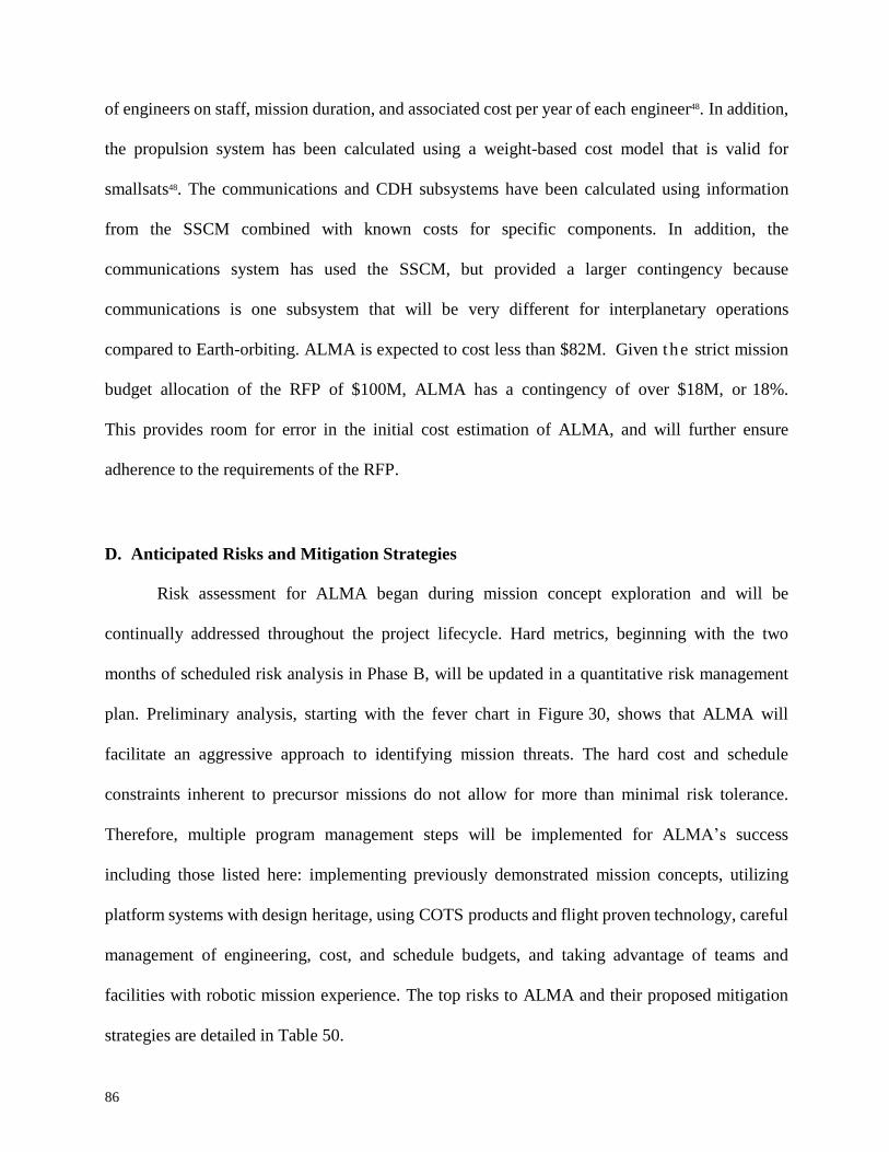
86
of engineers on staff, mission duration, and associated cost per year of each engineer48. In addition,
the propulsion system has been calculated using a weight-based cost model that is valid for
smallsats48. The communications and CDH subsystems have been calculated using information
from the SSCM combined with known costs for specific components. In addition, the
communications system has used the SSCM, but provided a larger contingency because
communications is one subsystem that will be very different for interplanetary operations
compared to Earth-orbiting. ALMA is expected to cost less than $82M. Given the strict mission
budget allocation of the RFP of $100M, ALMA has a contingency of over $18M, or 18%.
This provides room for error in the initial cost estimation of ALMA, and will further ensure
adherence to the requirements of the RFP.
D. Anticipated Risks and Mitigation Strategies
Risk assessment for ALMA began during mission concept exploration and will be
continually addressed throughout the project lifecycle. Hard metrics, beginning with the two
months of scheduled risk analysis in Phase B, will be updated in a quantitative risk management
plan. Preliminary analysis, starting with the fever chart in Figure 30, shows that ALMA will
facilitate an aggressive approach to identifying mission threats. The hard cost and schedule
constraints inherent to precursor missions do not allow for more than minimal risk tolerance.
Therefore, multiple program management steps will be implemented for ALMA’s success
including those listed here: implementing previously demonstrated mission concepts, utilizing
platform systems with design heritage, using COTS products and flight proven technology, careful
management of engineering, cost, and schedule budgets, and taking advantage of teams and
facilities with robotic mission experience. The top risks to ALMA and their proposed mitigation
strategies are detailed in Table 50.

87
Mission Risks
Risk Element
Mitigation Strategies Risk
Score
Impact
Likelihood
A
Telecommunications
link loss
Utilization of heritage communication
architecture through the DSN Scratch or GOTS development for HGA High power margins allocated for data
transmission
4
2
2
B
Shock failure –
thermal, acoustic
Heritage architecture technical approach Thorough environmental testing and part screening in schedule
Simple building block configuration bus
10
5
2
C
Science Data
Corrupt or
Incomplete
Reliable components Efficient data collection and transmission
operations robust to radiation
3
3
1
Implementation Risks
Risk Element
Mitigation Strategies Risk
Score
Impact
Likelihood
1
Science Payload
Development Risk
COTS TRL 9 FC/GRS with rad-hardening
High schedule (5 day/month) and cost (20%
mission) allocations for developments
Heritage custom rad-hardening techniques from asteroid and remote sensing missions
5
5
1
2
Missing intended launch date
Schedule and cost margins throughout design and construction
Research other launch dates in Phase B Risk Analysis
12
4
3
3
Infrastructure costs
and schedule
overages
Use of existing infrastructure Integration team margins
Small team accommodations
6
3
2
Table 50. Several mitigation strategies for each of ALMA’s primary risks accumulate to improve the feasibility
of the mission concept. Scores for each risk are determined by multiplying the mission impact score by the
mission likelihood for a comprehensive array of program threats.
Short transmission dumps
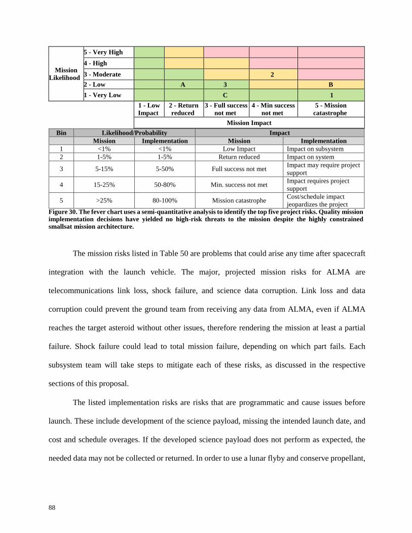
88
Mission
Likelihood
5 - Very High
4 - High
3 - Moderate
2
2 - Low A 3
B
1 - Very Low C
1
1 - Low
Impact 2 - Return
reduced 3 - Full success
not met 4 - Min success
not met 5 - Mission
catastrophe
Mission Impact
Bin Likelihood/Probability Impact
Mission Implementation Mission Implementation
1 <1% <1% Low Impact Impact on subsystem
2 1-5% 1-5% Return reduced Impact on system
3 5-15% 5-50% Full success not met Impact may require project
support
4 15-25% 50-80% Min. success not met Impact requires project
support
5 >25% 80-100% Mission catastrophe Cost/schedule impact
jeopardizes the project Figure 30. The fever chart uses a semi-quantitative analysis to identify the top five project risks. Quality mission implementation decisions have yielded no high-risk threats to the mission despite the highly constrained smallsat mission architecture.
The mission risks listed in Table 50 are problems that could arise any time after spacecraft
integration with the launch vehicle. The major, projected mission risks for ALMA are
telecommunications link loss, shock failure, and science data corruption. Link loss and data
corruption could prevent the ground team from receiving any data from ALMA, even if ALMA
reaches the target asteroid without other issues, therefore rendering the mission at least a partial
failure. Shock failure could lead to total mission failure, depending on which part fails. Each
subsystem team will take steps to mitigate each of these risks, as discussed in the respective
sections of this proposal.
The listed implementation risks are risks that are programmatic and cause issues before
launch. These include development of the science payload, missing the intended launch date, and
cost and schedule overages. If the developed science payload does not perform as expected, the
needed data may not be collected or returned. In order to use a lunar flyby and conserve propellant,

89
ALMA must be launched on a specific day. Missing this target, either due to missing a previous
deadline or due to unforeseen events, such as a storm, could lead to an extended waiting period
before another possible launch date arrives. Infrastructure costs and schedule overages could
contribute to a missed launch date or exceeding the mission budget. Mitigation strategies have and
will be used throughout the design process to ensure this will not happen.
ALMA management’s proactive approach to capture, track, and reduce risks throughout
the development and operations phases improves the feasibility of the already low-risk mission
concept. Other asteroid precursor mission approaches, including large space telescopes and
asteroid landers, require advanced technology which will incur heavy costs without serious risk
mitigation. ALMA’s use of demonstrated technology and commercial parts addresses the primary
risks inherent to the remote sensing architecture. The station keeping concept of operations also
reduces risk by avoiding uncertainties due to landing on an unknown asteroid, while still providing
more information in a shorter timeline than a telescope.
90
III. References
1Busch, M. W., Ostro, S. J., Benner, L. A., Brozovic, M., Giorgini, J. D., Jao, J. S., Scheeres, D. J., Magri, C., Nolan,
M. C., Howell, E. S., Taylor, P. A., Margot, J.-L., and Brisken, W., “Radar observations and the shape of near-Earth asteroid 2008 EV5,” Icarus, vol. 212, 2011, pp. 649–660.
2AIAA Foundation Student Design Competition 2015/16, “Low-Cost Asteroid Precursor Mission,” January 2016.
3“JPL Small-Body Database Browser,” JPL Small-Body Database Browser Available: http://ssd.jpl.nasa.gov/sbdb.cgi?sstr=2008 ev5;orb.
4Carry, B., “Density of asteroids,” Planetary and Space Science, vol. 73, 2012, pp. 98–118.
5Clark, P. E., and Rilee, M. L., Remote sensing tools for exploration: observing and interpreting the electromagnetic
spectrum, New York: Springer, 2010.
6Polanskey, C. A., Joy, S. P., and Raymond, C. A., “Dawn Science Planning, Operations and Archiving,” The Dawn
Mission to Minor Planets 4 Vesta and 1 Ceres, 2011, pp. 511–543.
7Lim, L. F., “46th Lunar and Planetary Science Conference (2015),” Measuring Bulk Carbon, Hydrogen, and Sulfur
from Orbit: Modeling Gamma-Ray Spectroscopy of Carbonaceous Asteroids, Houston.
8Mazanek, D. D., Merrill, R. G., Belbin, S. P., Reeves, D. M., Naasz, B. J., Abell, P. A., and Earle, K., “Asteroid
Redirect Robotic Mission: Robotic Boulder Capture Option Overview,” AIAA SPACE 2014 Conference and Exposition, 2014.
9Tedesco, E. F., Tholen, D. J., and Zellner, B., “The eight-color asteroid survey - Standard stars,” The Astronomical
Journal, vol. 87, 1982, p. 1585.
10Sierks, H., Keller, H. U., Jaumann, R., Michalik, H., Behnke, T., Bubenhagen, F., Büttner, I., Carsenty, U.,
Christensen, U., Enge, R., Fiethe, B., Marqués, P. G., Hartwig, H., Krüger, H., Kühne, W., Maue, T., Mottola, S., Nathues, A.,
Reiche, K.-U., Richards, M. L., Roatsch, T., Schröder, S. E., Szemerey, I., and Tschentscher, M., “The Dawn Framing Camera,”
The Dawn Mission to Minor Planets 4 Vesta and 1 Ceres, 2011, pp. 263–327.
11Boynton, W., Feldman, W., Mitrofanov, I., Evans, L., Reedy, R., Squyres, S., Starr, R., Trombka, J., D'uston, C.,
Arnold, J., Englert, P., Metzger, A., Wänke, H., Brückner, J., Drake, D., Shinohara, C., Fellows, C., Hamara, D., Harshman, K.,
Kerry, K., Turner, C., Ward, M., Barthe, H., Fuller, K., Storms, S., Thornton, G., Longmire, J., Litvak, M., and Ton'chev, A.,
“The Mars Odyssey Gamma-Ray Spectrometer Instrument Suite,” Space Science Reviews, vol. 110, 2004, pp. 37–83.
12ECAM-C50, Malin Space Science Systems, 2016.
13Mrozinski, J., "NASA Instrument Cost Model", 2016.
14Camera Calibration, University of Maryland, 2016.

91
15Schoneman, Scott, Amorosi, Lou, Cheke, Dan, & Chadwick, Mark, “Minotaur V Space Launch Vehicle for Small,
Cost-Effective Moon Exploration Missions”, SSC07-III-2
16"Rideshare Capabilities," United Launch Alliance, ULALaunch.com, 2015, URL:
http://www.ulalaunch.com/uploads/docs/About_ULA/2016_RideshareProductCard.pdf
17“Minotaur V Fact Sheet BR06006_3862”, Orbital ATK, Inc., 2015 URL: OrbitalATK.com
18Minotaur Program – Mission Development, Minotaur IV V VI User’s Guide, Release 2.2, Orbital ATK, Launch
Vehicles Division, Arizona, 2015
19 Sutton, G. P., and Biblarz, O., Rocket propulsion elements, New York: John Wiley &
Sons, 2001.
20 Mustafi, S., Francis, J., Li, X., DeLee, H., Purves, L., Lewis, D., Nixon, C., Mcguinness, D., Riall, S., Devine, M.,
and Hedayat, A., “Cryogenic Propulsion for the Titan Orbiter Polar Surveyor,” Aug. 2015.
21 Aerojet-Rocketdyne, “Bipropellant Data Sheets,” Bipropellant Rocket Engines Available:
http://www.rocket.com/propulsion-systems/bipropellant-rockets.
22 Upper Stage Engines, Moog ISP, 2016.
23 Mueller, T., “Liquid Rocket Components: Pyrotechnic Valves,”
http://www.maxentropy.net/rocketry/pyrovalve/PyroValve.pdf Apr. 2016
24 Borgmeyer, S. C., “Orbital Propulsion Fluidic Equipment,” Airbus Defense & Space Available: http://www.space-
propulsion.com/brochures/valves/space-propulsion-valves.pdf.
25 “Propulsion Systems,” Thales Available:
https://www.thalesgroup.com/sites/default/files/asset/document/propulsion_systems2012.pdf.
2002.
26 Brown, C. D., Elements of Spacecraft Design, Reston, VA: American Institute of Aeronautics and Astronautics,
27“Pressure Transducer,” Pressure Transducer Available:
http://www.moog.com/literature/space_defense/spacecraft/propulsion/stard_accuracy_pressure_transducer.pdf.
28“Liquid rocket systems,” Delft University of Technology Available:
http://www.lr.tudelft.nl/en/organisation/departments/space-engineering/space-systems-engineering/expertise-areas/space-
propulsion/propulsion-options/chemical-rockets/liquid/#2.
29“Data-sheet-index-PMD tanks,” Data-sheet-index-PMD tanks Available: http://www.psi-
pci.com/data_sheet_index_pmd-pn.htm.
30 Gerberich, M., and Oleson, S. R., “Estimation Model of Spacecraft Parameters and Cost Based on a Statistical
Analysis of COMPASS System Designs,” AIAA SPACE 2013 Conference and Exposition, 2013.
31Fisher, Jack, “Monopropellant Rocket Engines,” Aerojet Rocketdyne, Redmond, April 2006,URL:
http://www.rocket.com/files/aerojet/documents/Capabilities/PDFs/Monopropellant %20Data%20Sheets.pdf [cited 02 April
2016].
32Ellerbrock, Hartwig, “Hydrazine Thrusters,” Airbus Defence and Space, Ottobrunn, 2013, URL: http://www.space-
propulsion.com/brochures/hydrazine-thrusters/hydrazine-thrusters.pdf [cited 02 April 2016].
92
33“Monopropellant Thrusters,” Moog, Inc., Niagara Falls, 2013, URL:
http://www.moog.com/literature/Space_Defense/Spacecraft/Propulsion/Monopropellant_Thrusters_Rev_0613.pdf [cited 03 April
2016].
34 “LN-200S IMU,” Northrop Grumman Navigation and Maritime Systems, Woodland Hills, 2013, URL:
http://www.northropgrumman.com/Capabilities/LN200FOG/Documents/ ln200s.pdf [cited 09 April 2016].
35 “MIMU: Miniature Inertial Measurement Unit,” Honeywell, Clearwater, September 2003, URL:
https://www51.honeywell.com/aero/common/documents/myaerospacecatalog-documents/MIMU.pdf [cited 09 April 2016].
36 “ASTRIX 200,” Airbus Defence and Space, 2014, URL: http://www.space-
airbusds.com/media/document/gnc_4_astrix-200_2015-v_std_b-def.pdf [cited 09 April 2016].
37 “Second Generation Star Tracker (ST-16RT),” Sinclair Interplanetary, 2015, URL:
http://www.sinclairinterplanetary.com/startrackers [cited 11 April 2016].
38 “BCT Extended Baffle Nano Star Tracker,” Blue Canyon Technologies, Boulder, URL:
http://bluecanyontech.com/wp-content/uploads/2015/12/Ext-Baffle-NST-Data-Sheet_1.1.pdf [cited 01 April 2016].
39 “Procyon Star Tracker,” Surrey Satellite Technology, Guildford, 2015, URL:
https://www.sstl.co.uk/getattachment/c9a5e3e0-5ee6-4434-a2d4-b04ef6f767dd/Procyon-Star-Tracker [cited 19 April 2016].
40 “Rigel-L Star Tracker,” Surrey Satellite Technology, Guildford, 2014, URL:
https://www.sstl.co.uk/getattachment/15ebab75-8c95-4e32-865b-2e1a360728dd/Rigel-L-Star-Tracker [cited 19 April 2016].
41 “Solar MEMS SSOC-D60,” Solar MEMS Technologies, Sevilla, URL: http://www.solar-
mems.com/smt_pdf/commercial_brochure_SSOC-D.pdf [cited 19 April 2016].
42 “NSS Fine Sun Sensor Datasheet,” NewSpace Systems, Somerset West, URL: http://newspacesystems.com/wp-
content/themes/formationchild/datasheets/NSS_Fine_Sun_ Sensor_Datasheet_2b-.pdf [cited 19 April 2016].
43 “NSS Cubesat Sun Sensor,” NewSpace Systems, Somerset West, URL:
http://www.isispace.nl/brochures/NSS_Cubesat_Sun_Sensor_2a-.pdf [cited 19 April 2016].
44 “Solar MEMS nanoSSOC-A60,” Solar MEMS Technologies, Sevilla, URL: http://www.solar-
mems.com/smt_pdf/Brochure_NanoSSOC-A60.pdf [cited 19 April 2016].
45 “Solar MEMS nanoSSOC-D60,” Solar MEMS Technologies, Sevilla, URL: http://www.solar-
mems.com/smt_pdf/Brochure_NanoSSOC-D60.pdf [cited 19 April 2016].
46Spencer, D. A., Blanchard, R. C., Thurman, S. W., Braun, R. D., Peng, C., and Kallemeyn, P. H., “Mars Pathfinder
Atmospheric Entry Reconstruction,” AAS 98-146, 1998.

93
47 “Honeywell HG8500 Series Radar Altimeter,” Honeywell International Inc., Minneapolis, 2003, URL:
https://www51.honeywell.com/aero/common/documents/ myaerospacecatalog-
documents/MilitaryAC/HG8500_Radar_Altimeter.pdf [cited 19 April 2016].
48Wertz, J. R., Everett, D. F., and Puschell, J. J., Space mission engineering: the new SMAD, Hawthorne, CA:
Microcosm Press, 2011.
49Marc D Rayman, Thomas C. Fraschetti, Carol A. Raymon, Christopher T. Russel,
“Dawn: A mission in development for exploration of main belt asteroids Vesta and Ceres," ACTA Astronautica, vol. 15, p. 610, 2006.
50"Small Spacecraft Technology State of the Art," NASA/TP-2014-216648/REV1, Mission Design Division Staff, Ames
Research Center, California, 2014,2015.
51"RAD750 CompactPCI single-board computer", BAE Systems, Manassas, Virginia, 2008.
52"3U-160 CompactPCI SpaceWire interface board," BAE Systems, Manassas, Virginia, 2010.
53"NASA's Mission Operations and Communications Services AO NNH09ZDA007O," NASA's Announcement of Opportunity, January 2009.
54Noreen, G.K., Riley, A.L., and Pollmeier, V.M., "Small Deep Space Mission Telecommunications," Jet Propulsion
Laboratory, California Institute of Technology, Pasadena, California.
55”MLI materials,” Sheldahl: A Multek Brand, Northfield, URL:
http://www.sheldahl.com/Documents/Aerospace/MLI%20Materials.pdf, [cited 20 April 2016].
56”Spacecraft Thermal Control and Conductive Paints/Coatings and Service Catalog,” AZ Technology, Huntsville,
January 2008, URL: http://www.aztechnology.com/pdfs/materials-catalog.pdf, [cited 20 April 2016].
57”Small Spacecraft Technology State of the Art,” NASA, Moffett Field, December 2015, URL:
http://www.nasa.gov/sites/default/files/atoms/files/small_spacecraft_technology_state_of_the_art_2015_tagged.pdf, [cited 20
April 2016].
58Orbital ATK, Inc., Minotaur Mission History, 2015

94
IV. Nomenclature and Abbreviations
ADCS = Attitude Determination and Control System
ALMA = A Low-cost Mission to an Asteroid
ARM = Asteroid Redirect Mission
ARV = Asteroid Redirect Vehicle
AU = Astronomical Unit
BFL = Back Focal Length CDR = Command and Data Handling System CER = Cost Estimating Relationship
CONOPS = Concept of Operations
COTS = Commercial Off the Shelf
Deg = Degree DSN = Deep Space Network EV5 = 2008 EV5
FC = Framing Camera
FOV = Field of View
GaAs = Gallium Arsenide
GOTS = Government Off the Shelf GRaND = Gamma Ray and Neutron Detector HGA = High Gain Antenna
Hz = Hertz ICBM = Inter-Continental Ballistic Missile IFOV = Instantaneous Field of View
Isp = Specific Impulse IMU = Inertial Measurement Unit Kbps = Kilobits per second
Km/s = kilometers per second
Li Ion = Lithium Ion
MLI = Multilayer Insulation
MMH = Monomethyl Hydrazine
MOI = Moment of Inertia
NASA = National Aeronautics and Space Administration
NEA = Near Earth Asteroid
NiCd = Nickel Cadmium
NiH2 = Nickel Hydride
NTO = Nitrogen Tetroxide
RCS = Reaction Control Thrusters
RF = Radio Frequency RFP = Request for Proposal RTG = Radioisotope Thermoelectric Generator
SEP = Solar Electric Power Si = Silicon TLI = Translunar Injection
TRL = Technology Readiness Level USD = United States Dollar

95
V. Compliance Matrix
Element Page Number
Requirements Definition 24
Trade Studies
Precursor Mission Architecture 23
Target Selection 8-9
Mission Operations 23-78
Design Integration and Operation 23-78, 79-84
Cost Estimate 85-86
Summary 1-5
References 90-93
Concept and mission 7, 10-11
Science Approach 8-22
Communications Architecture 62-66
Mission Operations 25