ALLURAVISION™ SERIES ELECTRIC FIREPLACE · Napoleon Road arrie Ontario Canada LM aview rive arrie...
2
24 Napoleon Road, Barrie, Ontario, Canada L4M 0G8 • 214 Bayview Drive, Barrie, Ontario, Canada L4N 4Y8 Fireplaces, Heating and Cooling: 705-721-1212 • Grills: 705 726-4278 • napoleonproducts.com ALLURAVISION™ SERIES ELECTRIC FIREPLACE DATE 03/2018 Specifications Model BTU Width Height Depth Viewing Area Actual Framing Actual Framing Actual Framing NEFL32CHD 5000 32 5/8 33 1/8 15 7/8 16 1/8 5 13/16 6 1/16 30 13/16 x 11 1/16 NEFL42CHD 5000 42 1/16 42 9/16 15 7/8 16 1/8 5 13/16 6 1/16 40 1/4 x 11 1/16 NEFL50CHD 5000 50 5/16 50 13/16 15 7/8 16 1/8 5 13/16 6 1/16 48 1/2 x 11 1/16 NEFL60CHD 5000 60 3/16 60 11/16 15 7/8 16 1/8 5 13/16 6 1/16 58 5/16 x 11 1/16 NEFL74CHD 5000 74 5/16 74 13/16 15 7/8 16 1/8 5 13/16 6 1/16 72 1/2 x 11 1/16 NEFL100CHD 5000 100 5/16 100 13/16 15 7/8 16 1/8 5 13/16 6 1/16 98 1/2 x 11 1/16 NEFL32CHS 5000 32 5/8 33 1/8 15 7/8 16 1/8 4 1/4 4 1/2 30 13/16 x 11 1/16 NEFL42CHS 5000 42 1/16 42 9/16 15 7/8 16 1/8 4 1/4 4 1/2 40 1/4 x 11 1/16 NEFL50CHS 5000 50 5/16 50 13/16 15 7/8 16 1/8 4 1/4 4 1/2 48 1/2 x 11 1/16 NEFL60CHS 5000 60 3/16 60 11/16 15 7/8 16 1/8 4 1/4 4 1/2 58 5/16 x 11 1/16 NEFL74CHS 5000 74 5/16 74 13/16 15 7/8 16 1/8 4 1/4 4 1/2 72 1/2 x 11 1/16 NEFL100CHS 5000 100 5/16 100 13/16 15 7/8 16 1/8 4 1/4 4 1/2 98 1/2 x 11 1/16 A B F G VIEWING AREA CORD LOCATION Dimensions Model No. A B C D E F G H NEFL32CHS 35" (88.8cm) 17 5/16” (44cm) 4 1/4” (10.8cm) 15 7/8” (40.2cm) 32 5/8” (82.8cm) 30 13/16” (78.2cm) 11 1/16” (28.1cm) 3/4” (1.8cm) NEFL42CHS 44 7/16” (112.8cm) 17 5/16” (44cm) 4 1/4” (10.8cm) 15 7/8” (40.2cm) 42 1/16” (106.8cm) 40 1/4” (102.2cm) 11 1/16” (28.1cm) 3/4” (1.8cm) NEFL50CHS 52 11/16” (133.8cm) 17 5/16” (44cm) 4 1/4” (10.8cm) 15 7/8” (40.2cm) 50 5/16” (127.8cm) 48 1/2” (123.2cm) 11 1/16” (28.1cm) 3/4” (1.8cm) NEFL60CHS 62 9/16” (158.8cm) 17 5/16” (44cm) 4 1/4” (10.8cm) 15 7/8” (40.2cm) 60 3/16” (152.8cm) 58 5/16” (148.2cm) 11 1/16” (28.1cm) 3/4” (1.8cm) NEFL74CHS 76 3/4” (194.8cm) 17 5/16” (44cm) 4 1/4” (10.8cm) 15 7/8” (40.2cm) 74 5/16” (188.8cm) 72 1/2” (184.2cm) 11 1/16” (28.1cm) 3/4” (1.8cm) NEFL100CHS 102 11/16” (260.8cm) 17 5/16” (44cm) 4 1/4” (10.8cm) 15 7/8” (40.2cm) 100 5/16” (254.8cm) 98 1/2” (250.2cm) 11 1/16” (28.1cm) 3/4” (1.8cm) NEFL32CHD 35" (88.8cm) 17 5/16” (44cm) 5 13/16” (14.8cm) 15 7/8” (40.2cm) 32 5/8” (82.8cm) 30 13/16” (78.2cm) 11 1/16” (28.1cm) 3/4” (1.8cm) NEFL42CHD 44 7/16” (112.8cm) 17 5/16” (44cm) 5 13/16” (14.8cm) 15 7/8” (40.2cm) 42 1/16” (106.8cm) 40 1/4” (102.2cm) 11 1/16” (28.1cm) 3/4” (1.8cm) NEFL50CHD 52 11/16” (133.8cm) 17 5/16” (44cm) 5 13/16” (14.8cm) 15 7/8” (40.2cm) 50 5/16” (127.8cm) 48 1/2” (123.2cm) 11 1/16” (28.1cm) 3/4” (1.8cm) NEFL60CHD 62 9/16” (158.8cm) 17 5/16” (44cm) 5 13/16” (14.8cm) 15 7/8” (40.2cm) 60 3/16” (152.8cm) 58 5/16” (148.2cm) 11 1/16” (28.1cm) 3/4” (1.8cm) NEFL74CHD 76 3/4” (194.8cm) 17 5/16” (44cm) 5 13/16” (14.8cm) 15 7/8” (40.2cm) 74 5/16” (188.8cm) 72 1/2” (184.2cm) 11 1/16” (28.1cm) 3/4” (1.8cm) NEFL100CHD 102 11/16” (260.8cm) 17 5/16” (44cm) 5 13/16” (14.8cm) 15 7/8” (40.2cm) 100 5/16” (254.8cm) 98 1/2” (250.2cm) 11 1/16” (28.1cm) 3/4” (1.8cm) C D E H CORD LOCATION Product information provided is not complete and is subject to change without notice. Please consult the installation manual for the most up to date installation information.
Transcript of ALLURAVISION™ SERIES ELECTRIC FIREPLACE · Napoleon Road arrie Ontario Canada LM aview rive arrie...

24 Napoleon Road, Barrie, Ontario, Canada L4M 0G8 • 214 Bayview Drive, Barrie, Ontario, Canada L4N 4Y8Fireplaces, Heating and Cooling: 705-721-1212 • Grills: 705 726-4278 • napoleonproducts.com
ALLURAVISION™ SERIES ELECTRIC FIREPLACE
DATE 03/2018
Specifications
Model BTUWidth Height Depth
Viewing AreaActual Framing Actual Framing Actual Framing
NEFL32CHD 5000 32 5/8 33 1/8 15 7/8 16 1/8 5 13/16 6 1/16 30 13/16 x 11 1/16NEFL42CHD 5000 42 1/16 42 9/16 15 7/8 16 1/8 5 13/16 6 1/16 40 1/4 x 11 1/16NEFL50CHD 5000 50 5/16 50 13/16 15 7/8 16 1/8 5 13/16 6 1/16 48 1/2 x 11 1/16NEFL60CHD 5000 60 3/16 60 11/16 15 7/8 16 1/8 5 13/16 6 1/16 58 5/16 x 11 1/16NEFL74CHD 5000 74 5/16 74 13/16 15 7/8 16 1/8 5 13/16 6 1/16 72 1/2 x 11 1/16NEFL100CHD 5000 100 5/16 100 13/16 15 7/8 16 1/8 5 13/16 6 1/16 98 1/2 x 11 1/16NEFL32CHS 5000 32 5/8 33 1/8 15 7/8 16 1/8 4 1/4 4 1/2 30 13/16 x 11 1/16NEFL42CHS 5000 42 1/16 42 9/16 15 7/8 16 1/8 4 1/4 4 1/2 40 1/4 x 11 1/16NEFL50CHS 5000 50 5/16 50 13/16 15 7/8 16 1/8 4 1/4 4 1/2 48 1/2 x 11 1/16NEFL60CHS 5000 60 3/16 60 11/16 15 7/8 16 1/8 4 1/4 4 1/2 58 5/16 x 11 1/16NEFL74CHS 5000 74 5/16 74 13/16 15 7/8 16 1/8 4 1/4 4 1/2 72 1/2 x 11 1/16NEFL100CHS 5000 100 5/16 100 13/16 15 7/8 16 1/8 4 1/4 4 1/2 98 1/2 x 11 1/16
A
B
F
G VIEWING AREA
C
D
NOTE: MODEL SHOWN IS NEFL32CHS
E
H
CORD LOCATION
CORD LOCATION
FRONT VIEW RIGHT SIDE VIEW TOP VIEW
DimensionsModel No. A B C D E F G H
NEFL32CHS 35"(88.8cm)
17 5/16”(44cm)
4 1/4”(10.8cm)
15 7/8”(40.2cm)
32 5/8”(82.8cm)
30 13/16”(78.2cm)
11 1/16”(28.1cm)
3/4”(1.8cm)
NEFL42CHS 44 7/16”(112.8cm)
17 5/16”(44cm)
4 1/4”(10.8cm)
15 7/8”(40.2cm)
42 1/16”(106.8cm)
40 1/4”(102.2cm)
11 1/16”(28.1cm)
3/4”(1.8cm)
NEFL50CHS 52 11/16”(133.8cm)
17 5/16”(44cm)
4 1/4”(10.8cm)
15 7/8”(40.2cm)
50 5/16”(127.8cm)
48 1/2”(123.2cm)
11 1/16”(28.1cm)
3/4”(1.8cm)
NEFL60CHS 62 9/16”(158.8cm)
17 5/16”(44cm)
4 1/4”(10.8cm)
15 7/8”(40.2cm)
60 3/16”(152.8cm)
58 5/16”(148.2cm)
11 1/16”(28.1cm)
3/4”(1.8cm)
NEFL74CHS 76 3/4”(194.8cm)
17 5/16”(44cm)
4 1/4”(10.8cm)
15 7/8”(40.2cm)
74 5/16”(188.8cm)
72 1/2”(184.2cm)
11 1/16”(28.1cm)
3/4”(1.8cm)
NEFL100CHS 102 11/16”(260.8cm)
17 5/16”(44cm)
4 1/4”(10.8cm)
15 7/8”(40.2cm)
100 5/16”(254.8cm)
98 1/2”(250.2cm)
11 1/16”(28.1cm)
3/4”(1.8cm)
NEFL32CHD 35"(88.8cm)
17 5/16”(44cm)
5 13/16”(14.8cm)
15 7/8”(40.2cm)
32 5/8”(82.8cm)
30 13/16”(78.2cm)
11 1/16”(28.1cm)
3/4”(1.8cm)
NEFL42CHD 44 7/16”(112.8cm)
17 5/16”(44cm)
5 13/16”(14.8cm)
15 7/8”(40.2cm)
42 1/16”(106.8cm)
40 1/4”(102.2cm)
11 1/16”(28.1cm)
3/4”(1.8cm)
NEFL50CHD 52 11/16”(133.8cm)
17 5/16”(44cm)
5 13/16”(14.8cm)
15 7/8”(40.2cm)
50 5/16”(127.8cm)
48 1/2”(123.2cm)
11 1/16”(28.1cm)
3/4”(1.8cm)
NEFL60CHD 62 9/16”(158.8cm)
17 5/16”(44cm)
5 13/16”(14.8cm)
15 7/8”(40.2cm)
60 3/16”(152.8cm)
58 5/16”(148.2cm)
11 1/16”(28.1cm)
3/4”(1.8cm)
NEFL74CHD 76 3/4”(194.8cm)
17 5/16”(44cm)
5 13/16”(14.8cm)
15 7/8”(40.2cm)
74 5/16”(188.8cm)
72 1/2”(184.2cm)
11 1/16”(28.1cm)
3/4”(1.8cm)
NEFL100CHD 102 11/16”(260.8cm)
17 5/16”(44cm)
5 13/16”(14.8cm)
15 7/8”(40.2cm)
100 5/16”(254.8cm)
98 1/2”(250.2cm)
11 1/16”(28.1cm)
3/4”(1.8cm)
A
B
F
G VIEWING AREA
C
D
NOTE: MODEL SHOWN IS NEFL32CHS
E
H
CORD LOCATION
CORD LOCATION
FRONT VIEW RIGHT SIDE VIEW TOP VIEW
A
B
F
G VIEWING AREA
C
D
NOTE: MODEL SHOWN IS NEFL32CHS
E
H
CORD LOCATION
CORD LOCATION
FRONT VIEW RIGHT SIDE VIEW TOP VIEW
Product information provided is not complete and is subject to change without notice. Please consult the installation manual for the most up to date installation information.
24 Napoleon Road, Barrie, Ontario, Canada L4M 0G8 • 214 Bayview Drive, Barrie, Ontario, Canada L4N 4Y8Fireplaces, Heating and Cooling: 705-721-1212 • Grills: 705 726-4278 • napoleonproducts.com
ALLURAVISION™ SERIES ELECTRIC FIREPLACE
Date 03/2018
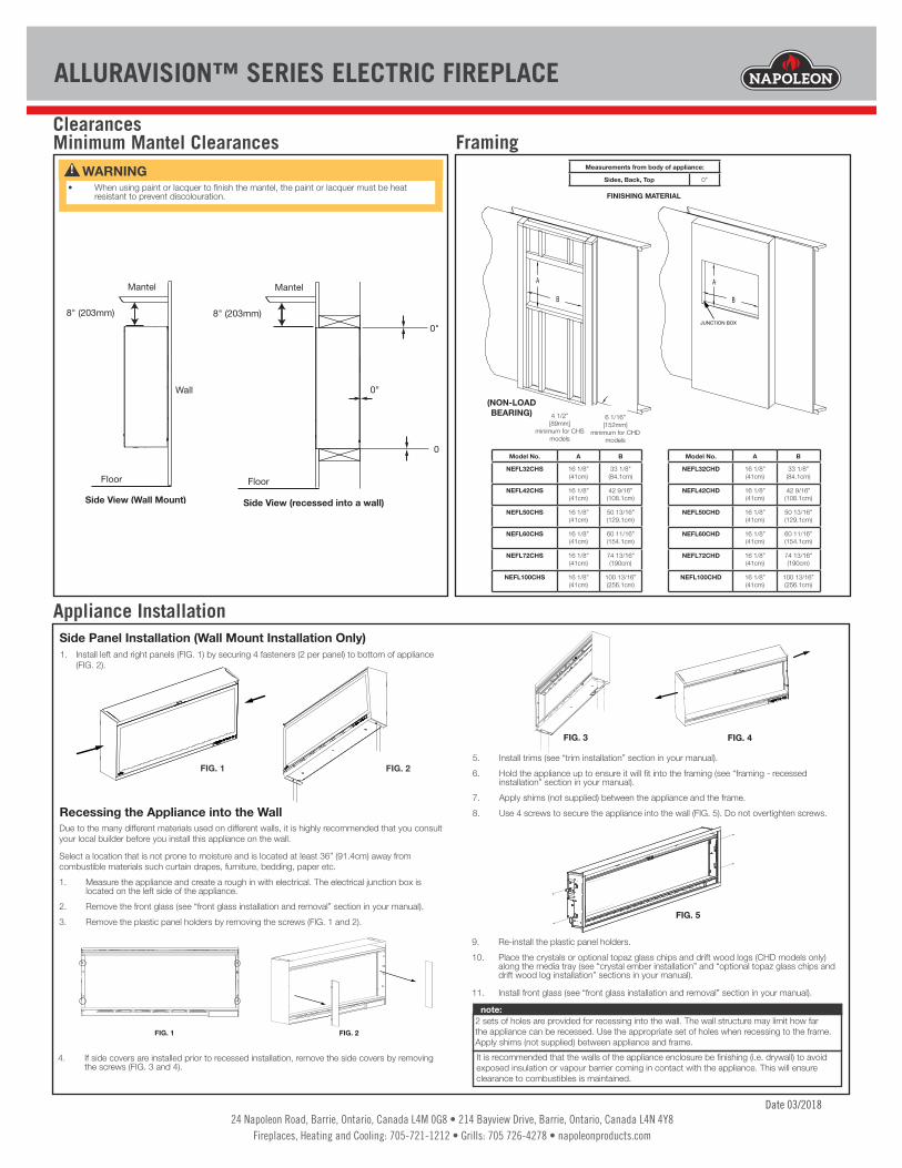
ClearancesMinimum Mantel Clearances
• When using paint or lacquer to finish the mantel, the paint or lacquer must be heat resistant to prevent discolouration.
! WARNING
Side View (Wall Mount)
8" (203mm)
Mantel
Floor
Wall
Side View (recessed into a wall)
8" (203mm)0"
0"
0"
Mantel
Floor
6 1/16"152mm
4 1/2"89mmMIN MAX
JUNCTION BOX
A
B
A
B
FINISHING MATERIAL
(NON-LOAD BEARING)
Model No. A B
NEFL32CHS 16 1/8”(41cm)
33 1/8”(84.1cm)
NEFL42CHS 16 1/8”(41cm)
42 9/16”(108.1cm)
NEFL50CHS 16 1/8”(41cm)
50 13/16”(129.1cm)
NEFL60CHS 16 1/8”(41cm)
60 11/16”(154.1cm)
NEFL72CHS 16 1/8”(41cm)
74 13/16”(190cm)
NEFL100CHS 16 1/8”(41cm)
100 13/16”(256.1cm)
Measurements from body of appliance:
Sides, Back, Top 0”
Model No. A B
NEFL32CHD 16 1/8”(41cm)
33 1/8”(84.1cm)
NEFL42CHD 16 1/8”(41cm)
42 9/16”(108.1cm)
NEFL50CHD 16 1/8”(41cm)
50 13/16”(129.1cm)
NEFL60CHD 16 1/8”(41cm)
60 11/16”(154.1cm)
NEFL72CHD 16 1/8”(41cm)
74 13/16”(190cm)
NEFL100CHD 16 1/8”(41cm)
100 13/16”(256.1cm)
4 1/2”[89mm]
minimum for CHS models
6 1/16”[152mm]
minimum for CHDmodels
Framing
Appliance Installation
1. Install left and right panels (FIG. 1) by securing 4 fasteners (2 per panel) to bottom of appliance (FIG. 2).
FIG. 1 FIG. 2
Side Panel Installation (Wall Mount Installation Only)
Due to the many different materials used on different walls, it is highly recommended that you consult your local builder before you install this appliance on the wall.
Select a location that is not prone to moisture and is located at least 36” (91.4cm) away from combustible materials such curtain drapes, furniture, bedding, paper etc.1. Measure the appliance and create a rough in with electrical. The electrical junction box is
located on the left side of the appliance.2. Remove the front glass (see “front glass installation and removal” section in your manual).3. Remove the plastic panel holders by removing the screws (FIG. 1 and 2).
5. Install trims (see “trim installation” section in your manual).6. Hold the appliance up to ensure it will fit into the framing (see “framing - recessed
installation” section in your manual).7. Apply shims (not supplied) between the appliance and the frame.8. Use 4 screws to secure the appliance into the wall (FIG. 5). Do not overtighten screws.
FIG. 1 FIG. 2
FIG. 4FIG. 3
4. If side covers are installed prior to recessed installation, remove the side covers by removing the screws (FIG. 3 and 4).
FIG. 5
9. Re-install the plastic panel holders.10. Place the crystals or optional topaz glass chips and drift wood logs (CHD models only)
along the media tray (see “crystal ember installation” and “optional topaz glass chips and drift wood log installation” sections in your manual).
11. Install front glass (see “front glass installation and removal” section in your manual).
Recessing the Appliance into the Wall
2 sets of holes are provided for recessing into the wall. The wall structure may limit how far the appliance can be recessed. Use the appropriate set of holes when recessing to the frame. Apply shims (not supplied) between appliance and frame.
note:
It is recommended that the walls of the appliance enclosure be finishing (i.e. drywall) to avoid exposed insulation or vapour barrier coming in contact with the appliance. This will ensure clearance to combustibles is maintained.