Allen-Bradley DH+/DH-485 Device Driver Helpftp.softwaretoolbox.com/.../v4_5/AllenBradley_DHP.pdf ·...
67
© 2009 Kepware Technologies Allen-Bradley DH+/DH-485 Device Driver Help
Transcript of Allen-Bradley DH+/DH-485 Device Driver Helpftp.softwaretoolbox.com/.../v4_5/AllenBradley_DHP.pdf ·...
© 2009 Kepware Technologies
Allen-Bradley DH+/DH-485Device Driver Help
Allen-Bradley DH+/DH-485 Device Driver Help1
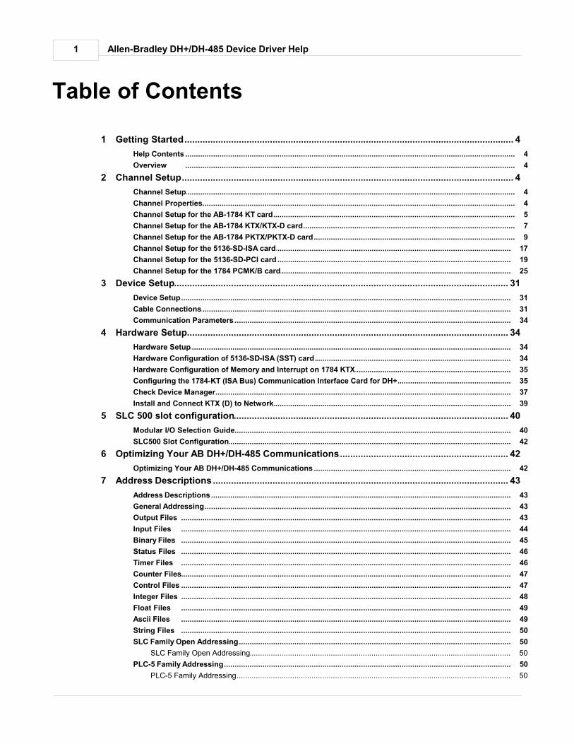
Table of Contents
................................................................................................................................... 41 Getting Started
.......................................................................................................................................................... 4Help Contents
.......................................................................................................................................................... 4Overview
................................................................................................................................... 42 Channel Setup
.......................................................................................................................................................... 4Channel Setup
.......................................................................................................................................................... 4Channel Properties
.......................................................................................................................................................... 5Channel Setup for the AB-1784 KT card
.......................................................................................................................................................... 7Channel Setup for the AB-1784 KTX/KTX-D card
.......................................................................................................................................................... 9Channel Setup for the AB-1784 PKTX/PKTX-D card
.......................................................................................................................................................... 17Channel Setup for the 5136-SD-ISA card
.......................................................................................................................................................... 19Channel Setup for the 5136-SD-PCI card
.......................................................................................................................................................... 25Channel Setup for the 1784 PCMK/B card
................................................................................................................................... 313 Device Setup
.......................................................................................................................................................... 31Device Setup
.......................................................................................................................................................... 31Cable Connections
.......................................................................................................................................................... 34Communication Parameters
................................................................................................................................... 344 Hardware Setup
.......................................................................................................................................................... 34Hardware Setup
.......................................................................................................................................................... 34Hardware Configuration of 5136-SD-ISA (SST) card
.......................................................................................................................................................... 35Hardware Configuration of Memory and Interrupt on 1784 KTX
.......................................................................................................................................................... 35Configuring the 1784-KT (ISA Bus) Communication Interface Card for DH+
.......................................................................................................................................................... 37Check Device Manager
.......................................................................................................................................................... 39Install and Connect KTX (D) to Network
................................................................................................................................... 405 SLC 500 slot configuration
.......................................................................................................................................................... 40Modular I/O Selection Guide
.......................................................................................................................................................... 42SLC500 Slot Configuration
................................................................................................................................... 426 Optimizing Your AB DH+/DH-485 Communications
.......................................................................................................................................................... 42Optimizing Your AB DH+/DH-485 Communications
................................................................................................................................... 437 Address Descriptions
.......................................................................................................................................................... 43Address Descriptions
.......................................................................................................................................................... 43General Addressing
.......................................................................................................................................................... 43Output Files
.......................................................................................................................................................... 44Input Files
.......................................................................................................................................................... 45Binary Files
.......................................................................................................................................................... 46Status Files
.......................................................................................................................................................... 46Timer Files
.......................................................................................................................................................... 47Counter Files
.......................................................................................................................................................... 47Control Files
.......................................................................................................................................................... 48Integer Files
.......................................................................................................................................................... 49Float Files
.......................................................................................................................................................... 49Ascii Files
.......................................................................................................................................................... 50String Files
.......................................................................................................................................................... 50SLC Family Open Addressing
......................................................................................................................................................... 50SLC Family Open Addressing
.......................................................................................................................................................... 50PLC-5 Family Addressing
......................................................................................................................................................... 50PLC-5 Family Addressing
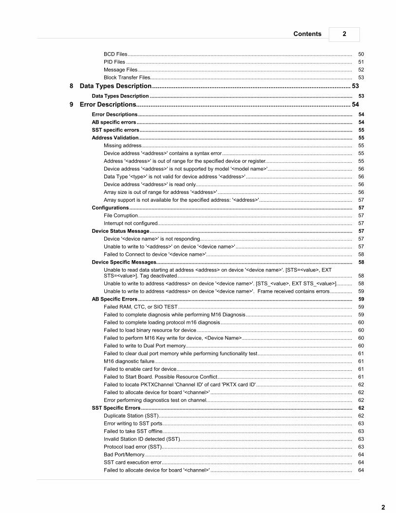
2Contents
2
......................................................................................................................................................... 50BCD Files
......................................................................................................................................................... 51PID Files
......................................................................................................................................................... 52Message Files
......................................................................................................................................................... 53Block Transfer Files
................................................................................................................................... 538 Data Types Description
.......................................................................................................................................................... 53Data Types Description
................................................................................................................................... 549 Error Descriptions
.......................................................................................................................................................... 54Error Descriptions
.......................................................................................................................................................... 54AB specific errors
.......................................................................................................................................................... 55SST specific errors
.......................................................................................................................................................... 55Address Validation
......................................................................................................................................................... 55Missing address
......................................................................................................................................................... 55Device address '<address>' contains a syntax error
......................................................................................................................................................... 55Address '<address>' is out of range for the specified device or register
......................................................................................................................................................... 56Device address '<address>' is not supported by model '<model name>'
......................................................................................................................................................... 56Data Type '<type>' is not valid for device address '<address>'
......................................................................................................................................................... 56Device address '<address>' is read only
......................................................................................................................................................... 56Array size is out of range for address '<address>'
......................................................................................................................................................... 57Array support is not available for the specified address: '<address>'
.......................................................................................................................................................... 57Configurations
......................................................................................................................................................... 57File Corruption
......................................................................................................................................................... 57Interrupt not configured
.......................................................................................................................................................... 57Device Status Message
......................................................................................................................................................... 57Device '<device name>' is not responding
......................................................................................................................................................... 57Unable to write to '<address>' on device '<device name>'
......................................................................................................................................................... 58Failed to Connect to device '<device name>'
.......................................................................................................................................................... 58Device Specific Messages
......................................................................................................................................................... 58Unable to read data starting at address <address> on device '<device name>'. [STS=<value>, EXTSTS=<value>]. Tag deactivated
......................................................................................................................................................... 58Unable to write to address <address> on device '<device name>'. [STS_<value>, EXT STS_<value>]
......................................................................................................................................................... 59Unable to write to address <address> on device '<device name>'. Frame received contains errors
.......................................................................................................................................................... 59AB Specific Errors
......................................................................................................................................................... 59Failed RAM, CTC, or SIO TEST
......................................................................................................................................................... 59Failed to complete diagnosis while performing M16 Diagnosis
......................................................................................................................................................... 60Failed to complete loading protocol m16 diagnosis
......................................................................................................................................................... 60Failed to load binary resource for device
......................................................................................................................................................... 60Failed to perform M16 Key write for device, <Device Name>
......................................................................................................................................................... 60Failed to write to Dual Port memory
......................................................................................................................................................... 61Failed to clear dual port memory while performing functionality test
......................................................................................................................................................... 61M16 diagnostic failure
......................................................................................................................................................... 61Failed to enable card for device
......................................................................................................................................................... 61Failed to Start Board. Possible Resource Conflict
......................................................................................................................................................... 62Failed to locate PKTXChannel 'Channel ID' of card 'PKTX card ID'
......................................................................................................................................................... 62Failed to allocate device for board '<channel>'
......................................................................................................................................................... 62Error performing diagnostics test on channel
.......................................................................................................................................................... 62SST Specific Errors
......................................................................................................................................................... 62Duplicate Station (SST)
......................................................................................................................................................... 63Error writing to SST ports
......................................................................................................................................................... 63Failed to take SST offline
......................................................................................................................................................... 63Invalid Station ID detected (SST)
......................................................................................................................................................... 63Protocol load error (SST)
......................................................................................................................................................... 64Bad Port/Memory
......................................................................................................................................................... 64SST card execution error
......................................................................................................................................................... 64Failed to allocate device for board '<channel>'

Allen-Bradley DH+/DH-485 Device Driver Help3
Index 65
4
www.kepware.com
Allen-Bradley DH+/DH-485 Device Driver Help
Allen-Bradley DH+/DH-485 Device Driver Help
Help version 1.019
CONTENTS
Overview
What is the Allen-Bradley DH+/DH-485 Device Driver? Channel Setup
How do I configure a channel for use with 1784 KTX(D), 1784 PKTX, 1784 PCMK/B, 5136-SD-ISA or 5136-SD-PCI? Device Setup
How do I configure a device for use with this driver? Hardware Setup
How do I configure hardware for use with this driver? Optimizing Your AB DH+/DH-485 Communications
How do I get the best performance from the Allen-Bradley DH+/DH-485 driver? Data Types Description
What data types are supported by this driver? Address Descriptions
How do I address a data location on an Allen-Bradley DH+/DH-485 device? Error Descriptions
What error messages are produced by the Allen-Bradley DH+/DH-485 driver?
Overview
The Allen-Bradley DH+/DH-485 Device Driver was specifically designed for use with 32 bit OPC server products runningon Intel microprocessor based computers. For operating system (OS) requirements, please refer to the OPC server helpdocumentation. This driver supports the Allen Bradley SLC family and PLC5 series PLCs, excluding the PLC5/250 series. Address rangesare open to support future models of these series of PLCs.
Channel Setup
Supported Network Cards
AB 1784-KT
AB 1784-KTX(D)
AB 1784-PKTX
AB-1784-PKTX(D)
AB 1784-PCMK/B
SST 5136-SD-ISA
SST 5136-SD-PCI and SST 5136-DHP-PCI
Supported Networks
Data Highway Plus (DH+)Data Highway-485 (DH-485): applicable to AB cards only.
Channel Properties
Board Type
This driver supports 8 different board types. They are KT, KTX, KTX-D, PKTX, PKTX-D and PCMK/B by Allen-Bradley and5136-SD-ISA and 5136-SD-PCI by SST.

5
www.kepware.com
Allen-Bradley DH+/DH-485 Device Driver Help
Note: In our board type selection, we will be choosing KTX (D) for both the KTX and KTX-D card.
Network Type
This driver supports both the DH+ and DH-485 network types. Each of the Allen-Bradley cards (KT, KTX, KTX-D, PKTX,PKTX-D and PCMK/B) support both DH+ and DH-485 networks. SST cards (5136-SD-ISA and 5136-SD-PCI) supportonly the DH+ network.
Station address
This is a unique node ID (0-77 octal for DH+ and 0-31 decimal for DH-485) of your device. You must make sure thatthis ID doesn't conflict with any other node ID on the network.
Baud Rate
There are several different baud rates that each of the card types support. The Allen-Bradley cards support 57.6K,115K and 230K for the DH+ network. For the DH-485 Network, the Allen-Bradley cards support 300, 600, 1.2K, 2.4K,4.8K, 9.6K and 19.2K. The SST cards as mentioned above support only the DH+ network, and the supported baudrates are 57.6K, 115K and 230K.
Memory Address
The ISA cards (KT, KTX, KTX-D and 5136-SD-ISA) require the user to manually set the memory address on the card.For more information on memory address setup, please refer to the appropriate catalogue. See Also: KTX (D)channel setup and5136-SD-ISA channel set up.
Interrupt
Each of the card types support interrupts. The PCI card types automatically set up the interrupts for your card. The ISAcards (KT, KTX, KTX-D and 5136-SD-ISA) require you to select a unique interrupt level from the drop down menu nextto the Interrupt label. Make sure it matches what you have selected while performing hardware configuration. Ifyou don't want to use interrupts, select None.
I/O Port Address
In addition to configuring the memory address on your 5136-SD-ISA card, you must also select a port addressmanually. Refer to the link below for more information.Please configure the I/O port and jumper settings on your SST ISA card. If the link does not provide youranswer, please refer to the appropriate SST catalogue that came with your card.
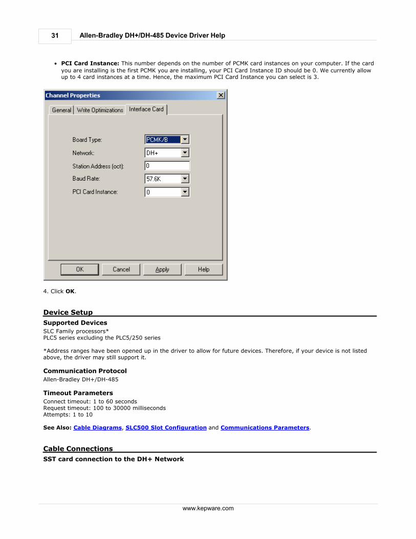
PCI Card Instance
This number depends on the number of similar PCI Card Instances on your computer. If the card is the first PCI you areinstalling, your PCI Card Instance should be 0. If the next PCI card you are installing is from the same vendor, the PCICard Instance for that card should be 1, etc. If, however, the next PCI card is from a different vendor and is the firstcard of that type you are installing, the PCI Card Instance should be 0. We currently allow up to 4 card instances at atime. Hence, the maximum PCI Card Instance you can select is 3.
PKTX Channel ID
PKTX cards come in two forms. It can either be a single channel (PKTX) or it can be a dual channel card (PKTX-D).Therefore, when a PKTX/PKTX-D card is used, the driver needs to know what channel it should be using. Selecting oneof the channels that shows up in the PKTX Channel ID drop down menu helps the driver know which channel to talk to.If you are using the PKTX-D card, select the channel (1 for PKTX Channel 1A and 2 for PKTX Channel 2) that you wantto use for your device.
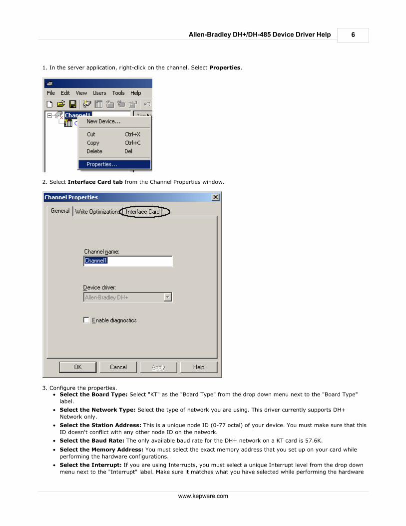
Channel Setup for the Allen Bradley- 1784 KT card
Before setting the channel properties, you must have the KT card configured for a unique memory address andinterrupt on the hardware. The selected address and interrupt should be noted, as these parameters will be used forsetting up the channel properties in the server.
Step 1: Configuration
Refer to your KT documents for Hardware configurations (Memory and Interrupt setup).
Step 2: Installation
Install the KT card on an available ISA slot and connect to the appropriate network.
Step 3: Channel Properties Setup for the KT Card.
6
www.kepware.com
Allen-Bradley DH+/DH-485 Device Driver Help
1. In the server application, right-click on the channel. Select Properties.
2. Select Interface Card tab from the Channel Properties window.
3. Configure the properties.
Select the Board Type: Select "KT" as the "Board Type" from the drop down menu next to the "Board Type"
label.
Select the Network Type: Select the type of network you are using. This driver currently supports DH+
Network only.
Select the Station Address: This is a unique node ID (0-77 octal) of your device. You must make sure that this
ID doesn't conflict with any other node ID on the network.
Select the Baud Rate: The only available baud rate for the DH+ network on a KT card is 57.6K.
Select the Memory Address: You must select the exact memory address that you set up on your card while
performing the hardware configurations.
Select the Interrupt: If you are using Interrupts, you must select a unique Interrupt level from the drop down
menu next to the "Interrupt" label. Make sure it matches what you have selected while performing the hardware
7
www.kepware.com
Allen-Bradley DH+/DH-485 Device Driver Help
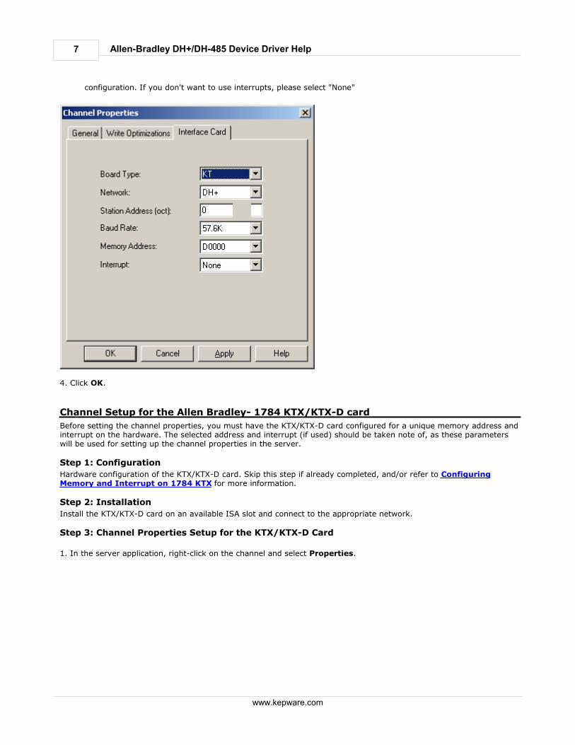
configuration. If you don't want to use interrupts, please select "None"
4. Click OK.
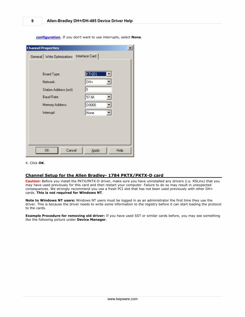
Channel Setup for the Allen Bradley- 1784 KTX/KTX-D card
Before setting the channel properties, you must have the KTX/KTX-D card configured for a unique memory address andinterrupt on the hardware. The selected address and interrupt (if used) should be taken note of, as these parameterswill be used for setting up the channel properties in the server.
Step 1: Configuration
Hardware configuration of the KTX/KTX-D card. Skip this step if already completed, and/or refer to ConfiguringMemory and Interrupt on 1784 KTX for more information.
Step 2: Installation
Install the KTX/KTX-D card on an available ISA slot and connect to the appropriate network.
Step 3: Channel Properties Setup for the KTX/KTX-D Card
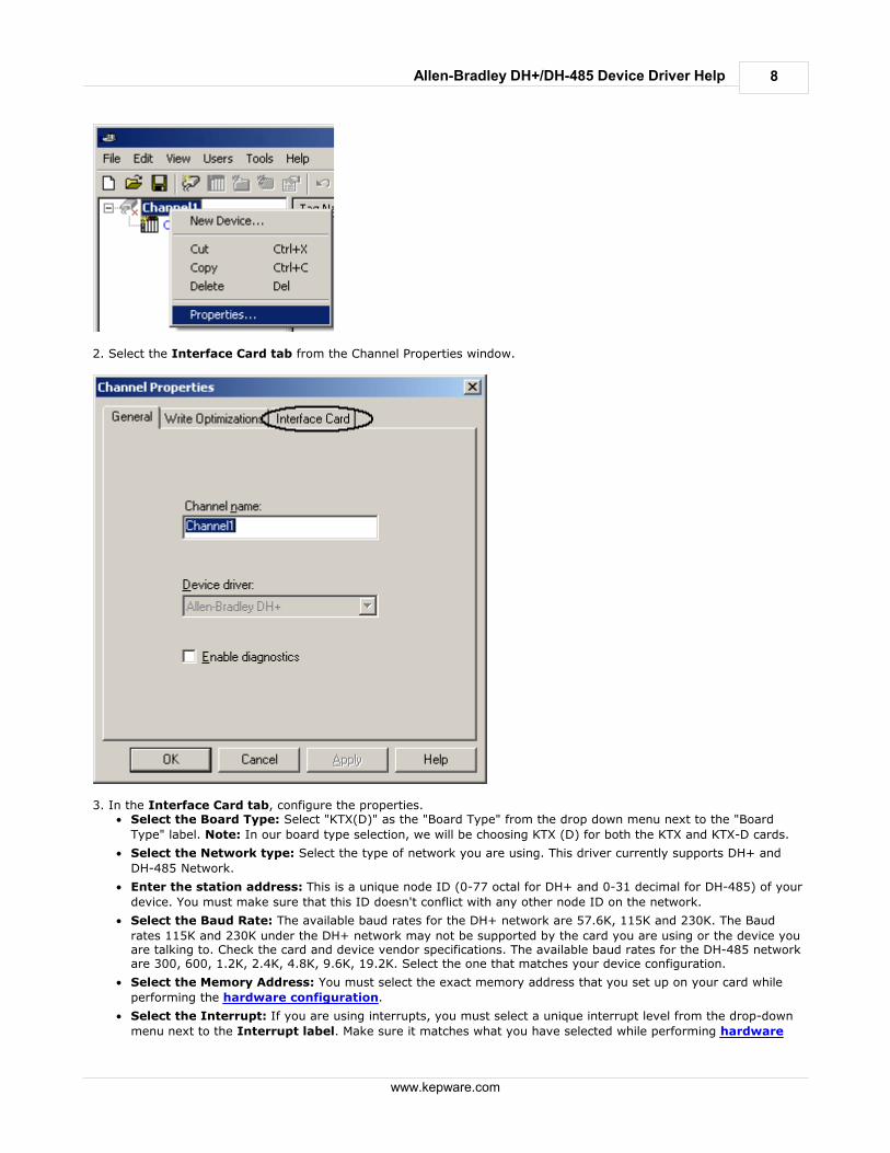
1. In the server application, right-click on the channel and select Properties.
8
www.kepware.com
Allen-Bradley DH+/DH-485 Device Driver Help
2. Select the Interface Card tab from the Channel Properties window.
3. In the Interface Card tab, configure the properties.
Select the Board Type: Select "KTX(D)" as the "Board Type" from the drop down menu next to the "Board
Type" label. Note: In our board type selection, we will be choosing KTX (D) for both the KTX and KTX-D cards.
Select the Network type: Select the type of network you are using. This driver currently supports DH+ and
DH-485 Network.
Enter the station address: This is a unique node ID (0-77 octal for DH+ and 0-31 decimal for DH-485) of your
device. You must make sure that this ID doesn't conflict with any other node ID on the network.
Select the Baud Rate: The available baud rates for the DH+ network are 57.6K, 115K and 230K. The Baud
rates 115K and 230K under the DH+ network may not be supported by the card you are using or the device youare talking to. Check the card and device vendor specifications. The available baud rates for the DH-485 networkare 300, 600, 1.2K, 2.4K, 4.8K, 9.6K, 19.2K. Select the one that matches your device configuration.
Select the Memory Address: You must select the exact memory address that you set up on your card while
performing the hardware configuration.
Select the Interrupt: If you are using interrupts, you must select a unique interrupt level from the drop-down
menu next to the Interrupt label. Make sure it matches what you have selected while performing hardware
9
www.kepware.com
Allen-Bradley DH+/DH-485 Device Driver Help
configuration. If you don't want to use interrupts, select None.
4. Click OK.
Channel Setup for the Allen Bradley- 1784 PKTX/PKTX-D card
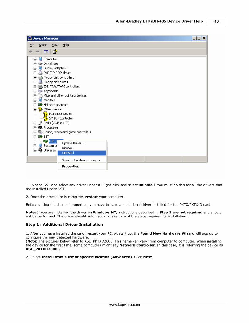
Caution: Before you install the PKTX/PKTX-D driver, make sure you have uninstalled any drivers (i.e. RSLinx) that youmay have used previously for this card and then restart your computer. Failure to do so may result in unexpectedconsequences. We strongly recommend you use a fresh PCI slot that has not been used previously with other DH+cards. This is not required for Windows NT. Note to Windows NT users: Windows NT users must be logged in as an administrator the first time they use thedriver. This is because the driver needs to write some information to the registry before it can start loading the protocolto the cards. Example Procedure for removing old driver: If you have used SST or similar cards before, you may see somethinglike the following picture under Device Manager.
10
www.kepware.com
Allen-Bradley DH+/DH-485 Device Driver Help
1. Expand SST and select any driver under it. Right-click and select uninstall. You must do this for all the drivers thatare installed under SST. 2. Once the procedure is complete, restart your computer. Before setting the channel properties, you have to have an additional driver installed for the PKTX/PKTX-D card. Note: If you are installing the driver on Windows NT, instructions described in Step 1 are not required and shouldnot be performed. The driver should automatically take care of the steps required for installation.
Step 1 : Additional Driver Installation
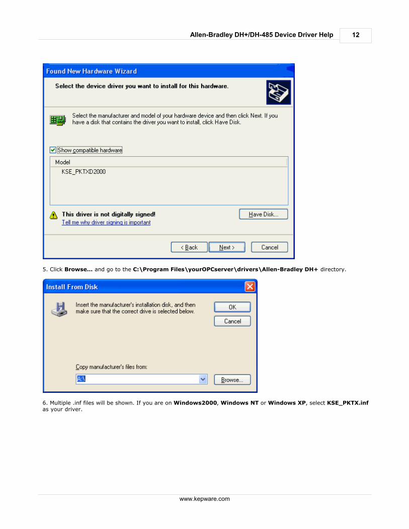
1. After you have installed the card, restart your PC. At start up, the Found New Hardware Wizard will pop up toconfigure the new detected hardware.(Note: The pictures below refer to KSE_PKTXD2000. This name can vary from computer to computer. When installingthe device for the first time, some computers might say Network Controller. In this case, it is referring the device asKSE_PKTXD2000.) 2. Select Install from a list or specific location (Advanced). Click Next.

11
www.kepware.com
Allen-Bradley DH+/DH-485 Device Driver Help
3. Select Don't search. I will choose the driver to install and click on Next.
4. Click Have Disk, regardless of whether or not the name PKTX appears on the list.
12
www.kepware.com
Allen-Bradley DH+/DH-485 Device Driver Help
5. Click Browse... and go to the C:\Program Files\yourOPCserver\drivers\Allen-Bradley DH+ directory.
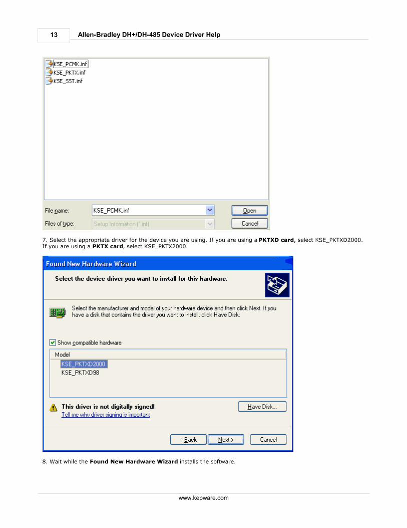
6. Multiple .inf files will be shown. If you are on Windows2000, Windows NT or Windows XP, select KSE_PKTX.infas your driver.
13
www.kepware.com
Allen-Bradley DH+/DH-485 Device Driver Help
7. Select the appropriate driver for the device you are using. If you are using a PKTXD card, select KSE_PKTXD2000.If you are using a PKTX card, select KSE_PKTX2000.
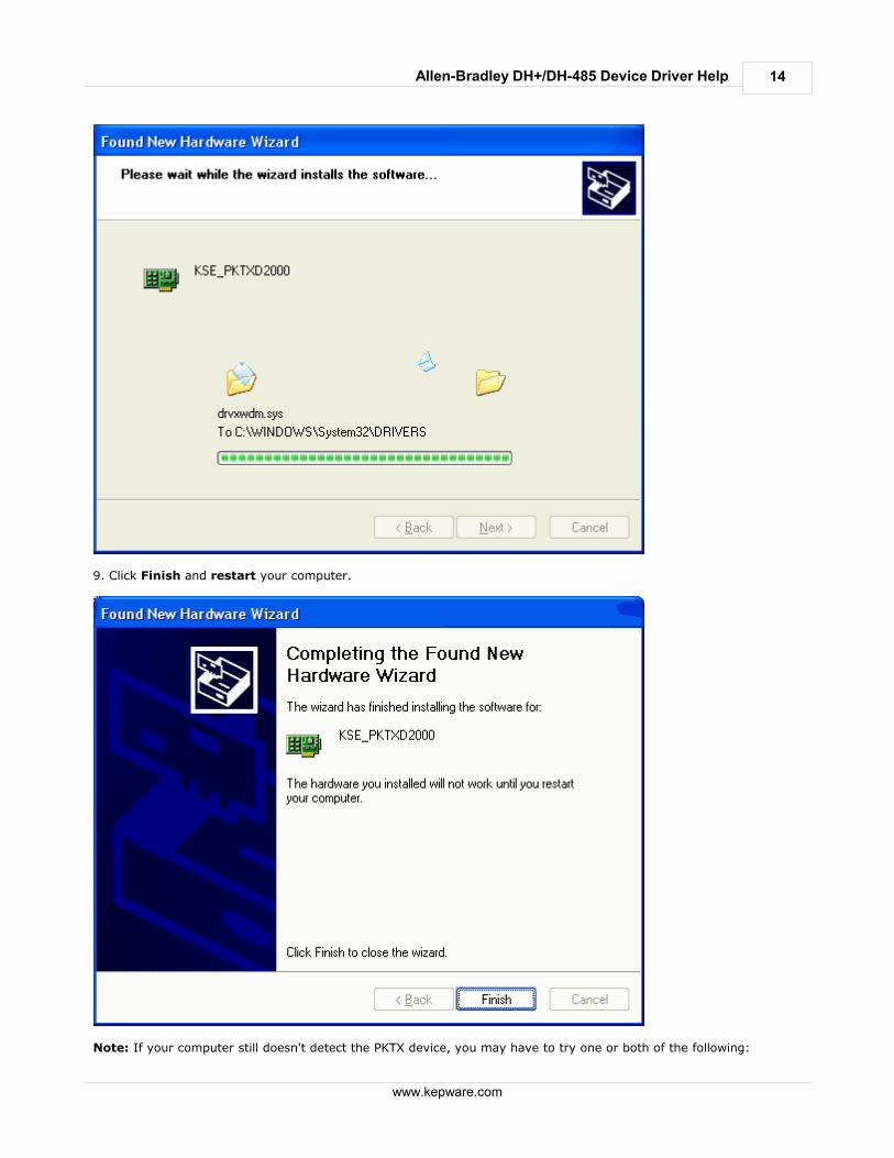
8. Wait while the Found New Hardware Wizard installs the software.
14
www.kepware.com
Allen-Bradley DH+/DH-485 Device Driver Help
9. Click Finish and restart your computer.
Note: If your computer still doesn't detect the PKTX device, you may have to try one or both of the following:
15
www.kepware.com
Allen-Bradley DH+/DH-485 Device Driver Help
1. Completely uninstall any driver installed under the current slot.2. Try a different slot.
Step 2: Channel Configuration
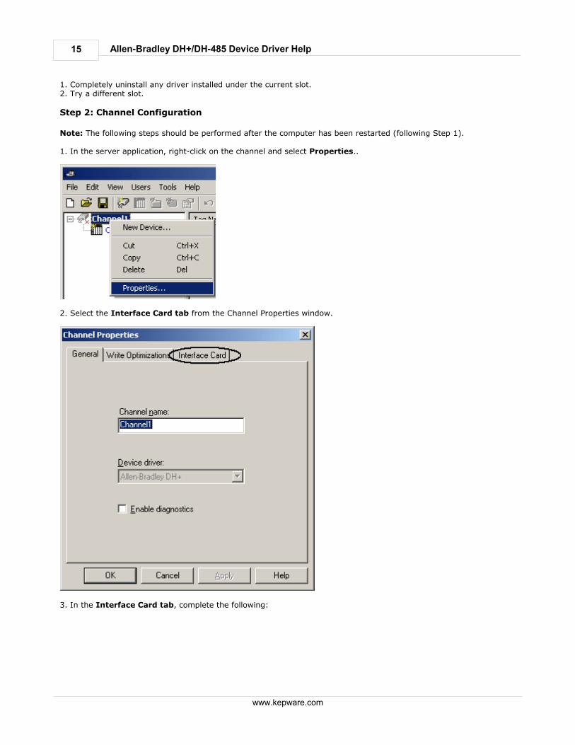
Note: The following steps should be performed after the computer has been restarted (following Step 1). 1. In the server application, right-click on the channel and select Properties..
2. Select the Interface Card tab from the Channel Properties window.
3. In the Interface Card tab, complete the following:

16
www.kepware.com
Allen-Bradley DH+/DH-485 Device Driver Help
Select the Board Type: Select "PKTX" or " PKTX-D" as the "Board Type" (depending on whether you are using
PKTX or PKTX-D card) from the drop down menu next to the "Board Type" label.
Select the Network type: This driver currently supports DH+ and DH-485 networks for PKTX/PKTX-D cards.
Enter the station address: This is a unique node ID (0-77 octal for DH+ and 0-31 decimal for DH-485) of your
device. You must make sure that this ID doesn't conflict with any other node ID on the network.
Select the Baud Rate: The available baud rates for the DH+ network are 57.6K, 115K and 230K.The Baud rates
115K and 230K under the DH+ network may not be supported by the card you are using or the device you aretalking to. Check the card and device vendor specifications. The available baud rates for the DH-485 network are300, 600, 1.2K, 2.4K, 4.8K, 9.6K, 19.2K. Select the one that matches your device configuration.
PCI Card Instance: On Windows XP/2000, this number depends on the number of PKTX/PKTX-D card instances
on your computer. If the card you are installing is the first PKTX/PKTX-D, your PCI Card Instance should be 0.The PCI Card Instance for the next PKTX/PKTX-D card will be 1 etc. On Windows NT however, PKTX and PKTX-Dcards are treated as two different types of cards. Hence, if you have two cards installed (one PKTX and onePKTX-D), the PCI Card Instance for both cards will be 0. The PCI Card Instance for the next PKTX will be 1 andfor the next PKTX-D card will also be 1 etc. We currently allow up to 4 card instances altogether at a time.Hence, the maximum PCI Card Instance you can select is 3.
PKTX Channel: This number depends on the number of channels on your PKTX Card. If you are using a PKTX
card, you would have only one channel. However, if you are using PKTX-D, you would have two differentchannels. If you are using the PKTX-D card, please select the channel (1 for PKTX Channel 1A and 2 for PKTXChannel 2) that you would want to use for your device.
17
www.kepware.com
Allen-Bradley DH+/DH-485 Device Driver Help
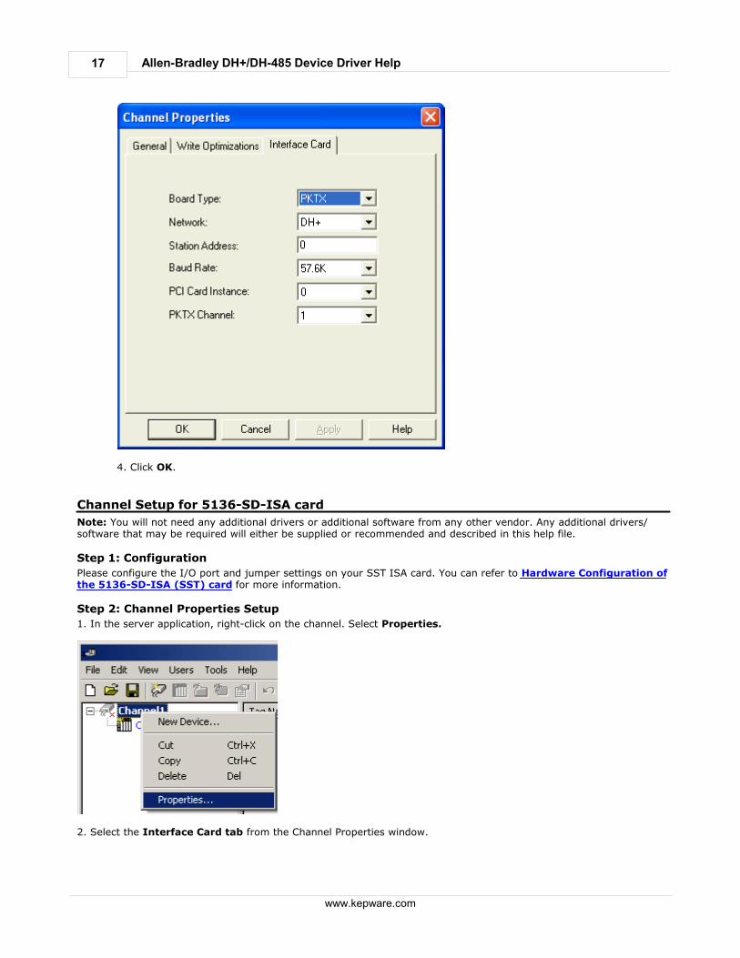
4. Click OK.
Channel Setup for 5136-SD-ISA card
Note: You will not need any additional drivers or additional software from any other vendor. Any additional drivers/software that may be required will either be supplied or recommended and described in this help file.
Step 1: Configuration
Please configure the I/O port and jumper settings on your SST ISA card. You can refer to Hardware Configuration ofthe 5136-SD-ISA (SST) card for more information.
Step 2: Channel Properties Setup
1. In the server application, right-click on the channel. Select Properties.
2. Select the Interface Card tab from the Channel Properties window.
18
www.kepware.com
Allen-Bradley DH+/DH-485 Device Driver Help
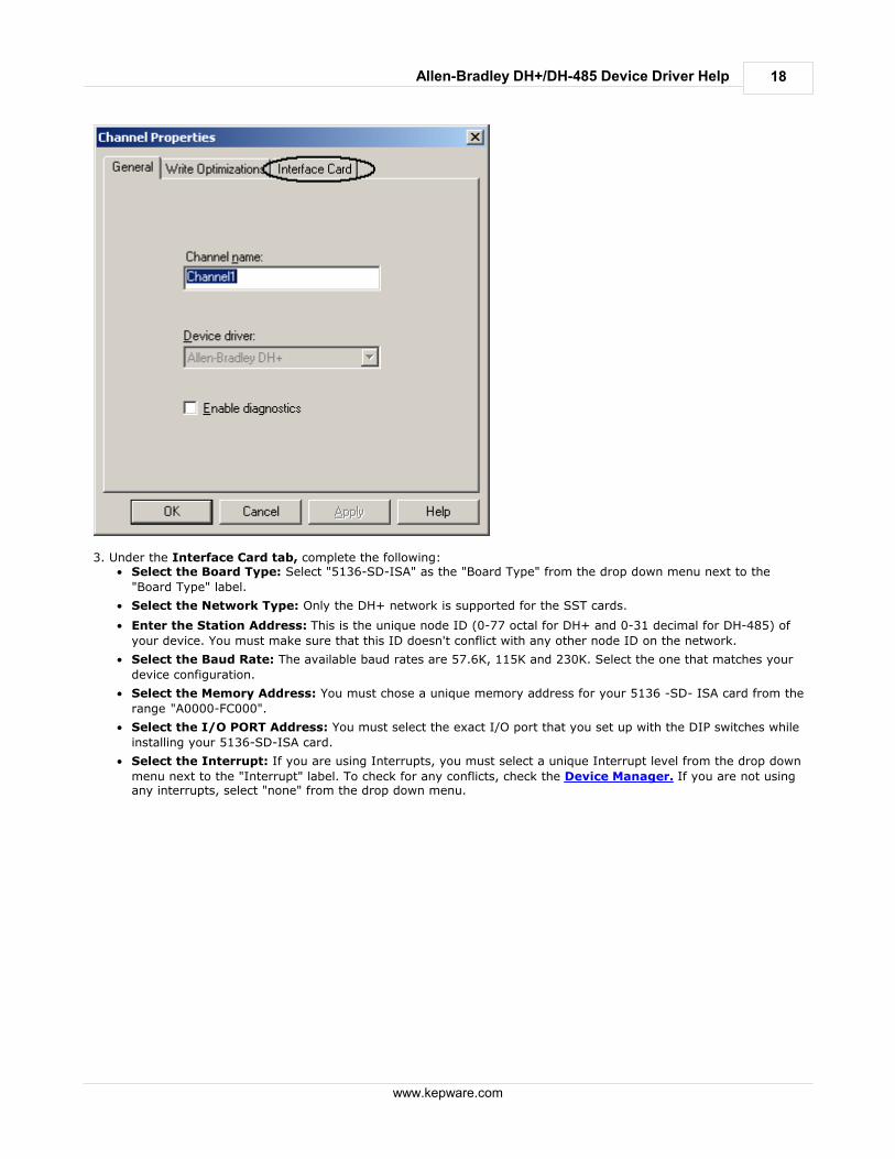
3. Under the Interface Card tab, complete the following:
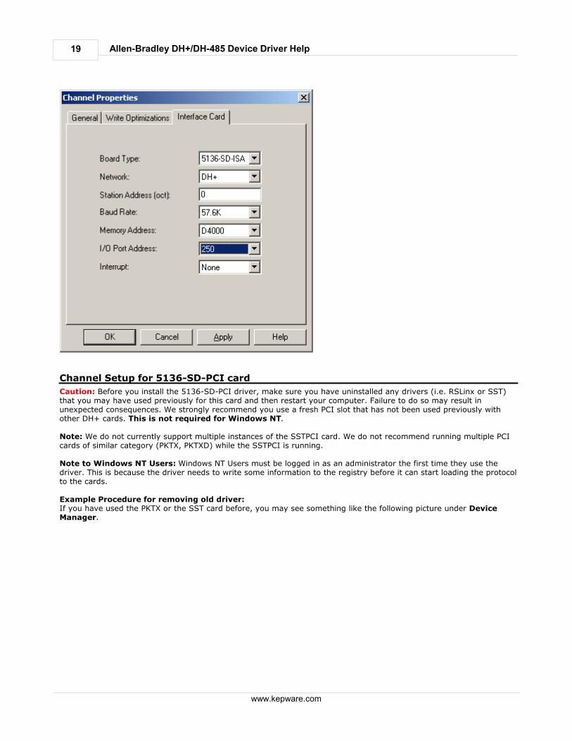
Select the Board Type: Select "5136-SD-ISA" as the "Board Type" from the drop down menu next to the
"Board Type" label.
Select the Network Type: Only the DH+ network is supported for the SST cards.
Enter the Station Address: This is the unique node ID (0-77 octal for DH+ and 0-31 decimal for DH-485) of
your device. You must make sure that this ID doesn't conflict with any other node ID on the network.
Select the Baud Rate: The available baud rates are 57.6K, 115K and 230K. Select the one that matches your
device configuration.
Select the Memory Address: You must chose a unique memory address for your 5136 -SD- ISA card from the
range "A0000-FC000".
Select the I/O PORT Address: You must select the exact I/O port that you set up with the DIP switches while
installing your 5136-SD-ISA card.
Select the Interrupt: If you are using Interrupts, you must select a unique Interrupt level from the drop down
menu next to the "Interrupt" label. To check for any conflicts, check the Device Manager. If you are not usingany interrupts, select "none" from the drop down menu.
19
www.kepware.com
Allen-Bradley DH+/DH-485 Device Driver Help
Channel Setup for 5136-SD-PCI card
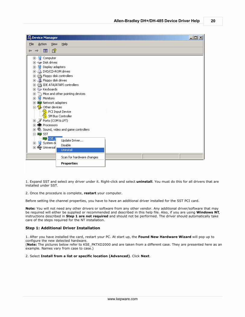
Caution: Before you install the 5136-SD-PCI driver, make sure you have uninstalled any drivers (i.e. RSLinx or SST)that you may have used previously for this card and then restart your computer. Failure to do so may result inunexpected consequences. We strongly recommend you use a fresh PCI slot that has not been used previously withother DH+ cards. This is not required for Windows NT. Note: We do not currently support multiple instances of the SSTPCI card. We do not recommend running multiple PCIcards of similar category (PKTX, PKTXD) while the SSTPCI is running. Note to Windows NT Users: Windows NT Users must be logged in as an administrator the first time they use thedriver. This is because the driver needs to write some information to the registry before it can start loading the protocolto the cards. Example Procedure for removing old driver:If you have used the PKTX or the SST card before, you may see something like the following picture under DeviceManager.
20
www.kepware.com
Allen-Bradley DH+/DH-485 Device Driver Help
1. Expand SST and select any driver under it. Right-click and select uninstall. You must do this for all drivers that areinstalled under SST. 2. Once the procedure is complete, restart your computer. Before setting the channel properties, you have to have an additional driver installed for the SST PCI card. Note: You will not need any other drivers or software from any other vendor. Any additional driver/software that maybe required will either be supplied or recommended and described in this help file. Also, if you are using Windows NT,instructions described in Step 1 are not required and should not be performed. The driver should automatically takecare of the steps required for the NT installation.
Step 1: Additional Driver Installation
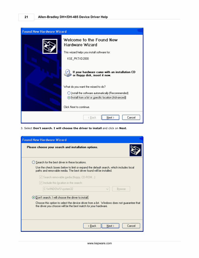
1. After you have installed the card, restart your PC. At start up, the Found New Hardware Wizard will pop up toconfigure the new detected hardware.(Note: The pictures below refer to KSE_PKTXD2000 and are taken from a different case. They are presented here as anexample. Names vary from case to case.) 2. Select Install from a list or specific location (Advanced). Click Next.
21
www.kepware.com
Allen-Bradley DH+/DH-485 Device Driver Help
3. Select Don't search. I will choose the driver to install and click on Next.
22
www.kepware.com
Allen-Bradley DH+/DH-485 Device Driver Help
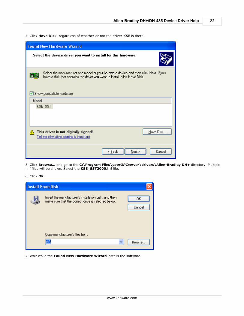
4. Click Have Disk, regardless of whether or not the driver KSE is there.
5. Click Browse... and go to the C:\Program Files\yourOPCserver\drivers\Allen-Bradley DH+ directory. Multiple.inf files will be shown. Select the KSE_SST2000.inf file. 6. Click OK.
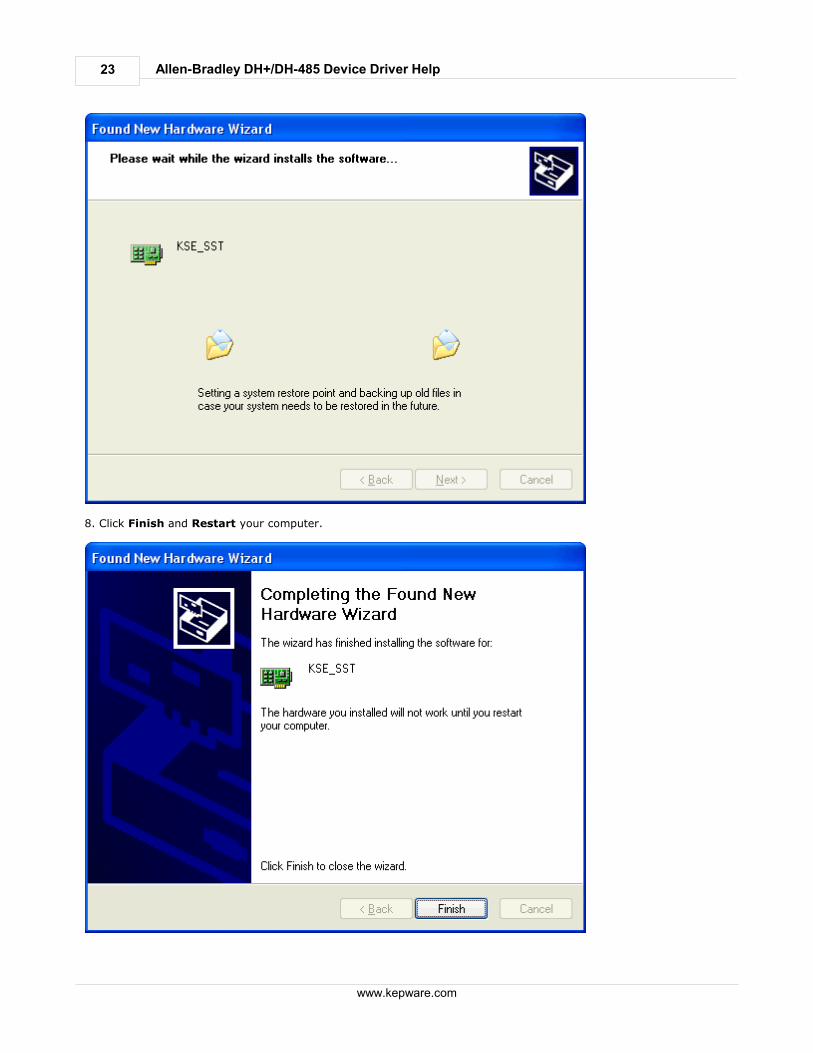
7. Wait while the Found New Hardware Wizard installs the software.
23
www.kepware.com
Allen-Bradley DH+/DH-485 Device Driver Help
8. Click Finish and Restart your computer.
24
www.kepware.com
Allen-Bradley DH+/DH-485 Device Driver Help
Note: If your computer still doesn't detect the SST-PCI device, you may have to try one or both of the following:1. Completely uninstall any driver installed under the current slot.2. Try a different PCI slot.
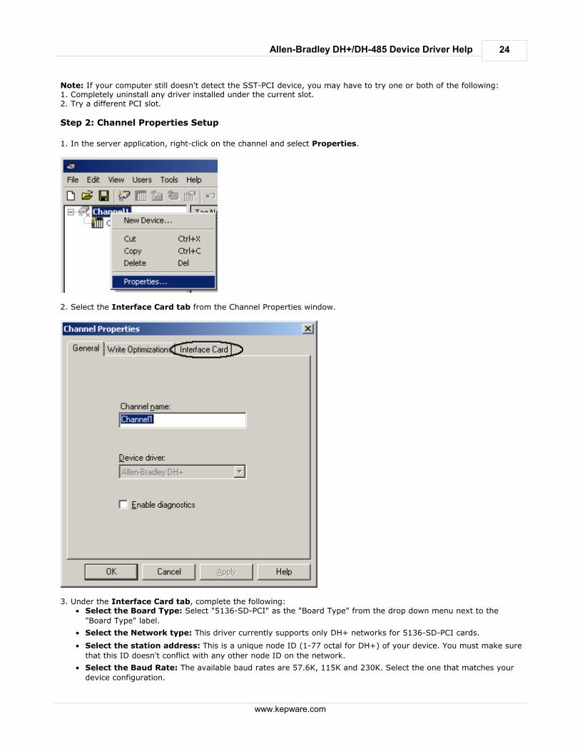
Step 2: Channel Properties Setup
1. In the server application, right-click on the channel and select Properties.
2. Select the Interface Card tab from the Channel Properties window.
3. Under the Interface Card tab, complete the following:
Select the Board Type: Select "5136-SD-PCI" as the "Board Type" from the drop down menu next to the
"Board Type" label.
Select the Network type: This driver currently supports only DH+ networks for 5136-SD-PCI cards.
Select the station address: This is a unique node ID (1-77 octal for DH+) of your device. You must make sure
that this ID doesn't conflict with any other node ID on the network.
Select the Baud Rate: The available baud rates are 57.6K, 115K and 230K. Select the one that matches your
device configuration.
25
www.kepware.com
Allen-Bradley DH+/DH-485 Device Driver Help
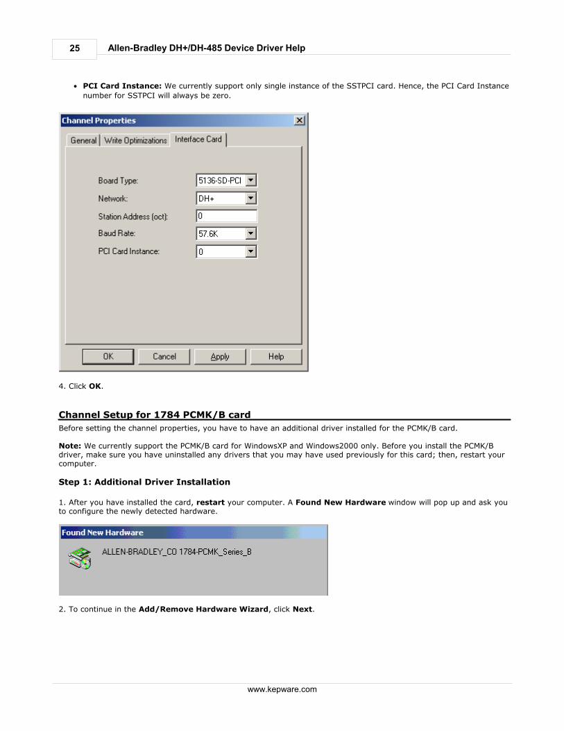
PCI Card Instance: We currently support only single instance of the SSTPCI card. Hence, the PCI Card Instance
number for SSTPCI will always be zero.
4. Click OK.
Channel Setup for 1784 PCMK/B card
Before setting the channel properties, you have to have an additional driver installed for the PCMK/B card. Note: We currently support the PCMK/B card for WindowsXP and Windows2000 only. Before you install the PCMK/Bdriver, make sure you have uninstalled any drivers that you may have used previously for this card; then, restart yourcomputer.
Step 1: Additional Driver Installation
1. After you have installed the card, restart your computer. A Found New Hardware window will pop up and ask youto configure the newly detected hardware.
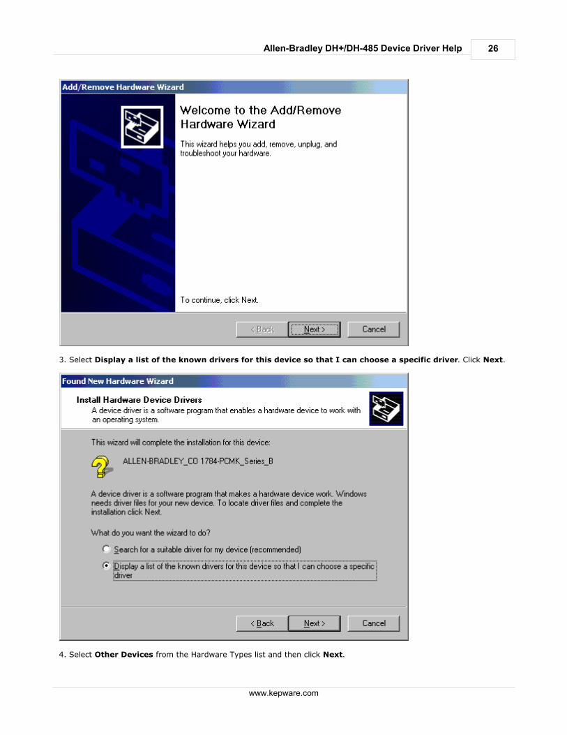
2. To continue in the Add/Remove Hardware Wizard, click Next.
26
www.kepware.com
Allen-Bradley DH+/DH-485 Device Driver Help
3. Select Display a list of the known drivers for this device so that I can choose a specific driver. Click Next.
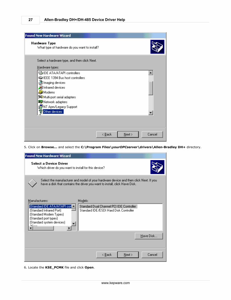
4. Select Other Devices from the Hardware Types list and then click Next.
27
www.kepware.com
Allen-Bradley DH+/DH-485 Device Driver Help
5. Click on Browse... and select the C:\Program Files\yourOPCserver\drivers\Allen-Bradley DH+ directory.
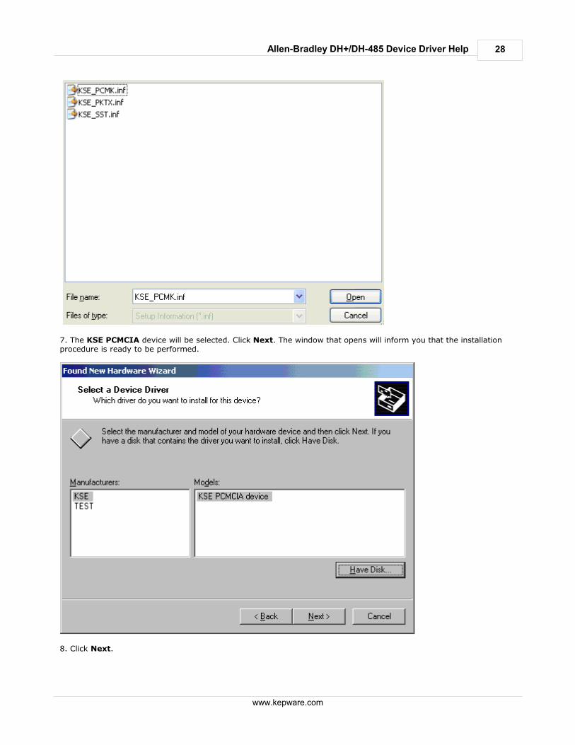
6. Locate the KSE_PCMK file and click Open.
28
www.kepware.com
Allen-Bradley DH+/DH-485 Device Driver Help
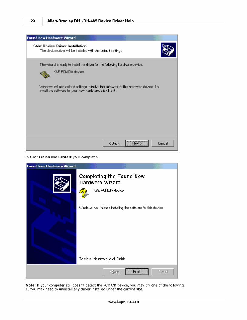
7. The KSE PCMCIA device will be selected. Click Next. The window that opens will inform you that the installationprocedure is ready to be performed.
8. Click Next.
29
www.kepware.com
Allen-Bradley DH+/DH-485 Device Driver Help
9. Click Finish and Restart your computer.
Note: If your computer still doesn't detect the PCMK/B device, you may try one of the following.1. You may need to uninstall any driver installed under the current slot.
30
www.kepware.com
Allen-Bradley DH+/DH-485 Device Driver Help
2. You may need to try a different slot.
Step 2: Channel Properties Setup
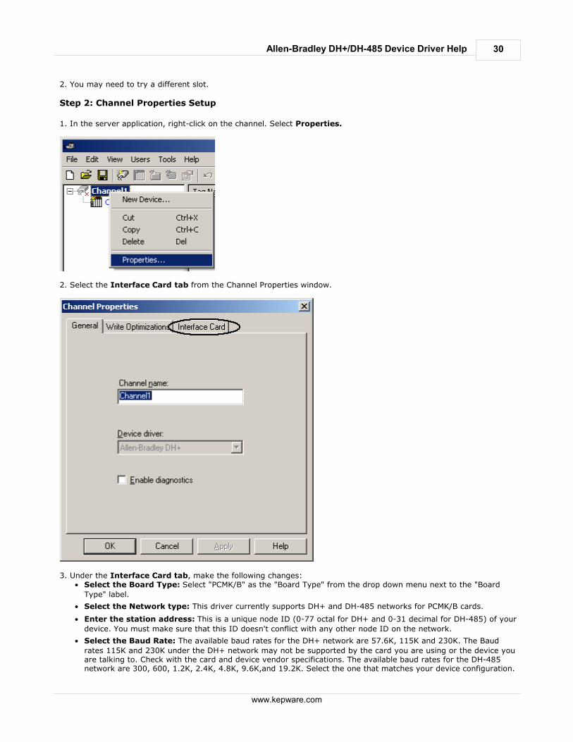
1. In the server application, right-click on the channel. Select Properties.
2. Select the Interface Card tab from the Channel Properties window.
3. Under the Interface Card tab, make the following changes:
Select the Board Type: Select "PCMK/B" as the "Board Type" from the drop down menu next to the "Board
Type" label.
Select the Network type: This driver currently supports DH+ and DH-485 networks for PCMK/B cards.
Enter the station address: This is a unique node ID (0-77 octal for DH+ and 0-31 decimal for DH-485) of your
device. You must make sure that this ID doesn't conflict with any other node ID on the network.
Select the Baud Rate: The available baud rates for the DH+ network are 57.6K, 115K and 230K. The Baud
rates 115K and 230K under the DH+ network may not be supported by the card you are using or the device youare talking to. Check with the card and device vendor specifications. The available baud rates for the DH-485network are 300, 600, 1.2K, 2.4K, 4.8K, 9.6K,and 19.2K. Select the one that matches your device configuration.
31
www.kepware.com
Allen-Bradley DH+/DH-485 Device Driver Help
PCI Card Instance: This number depends on the number of PCMK card instances on your computer. If the card
you are installing is the first PCMK you are installing, your PCI Card Instance ID should be 0. We currently allowup to 4 card instances at a time. Hence, the maximum PCI Card Instance you can select is 3.
4. Click OK.
Device Setup
Supported Devices
SLC Family processors*PLC5 series excluding the PLC5/250 series *Address ranges have been opened up in the driver to allow for future devices. Therefore, if your device is not listedabove, the driver may still support it.
Communication Protocol
Allen-Bradley DH+/DH-485
Timeout Parameters
Connect timeout: 1 to 60 secondsRequest timeout: 100 to 30000 millisecondsAttempts: 1 to 10 See Also: Cable Diagrams, SLC500 Slot Configuration and Communications Parameters.
Cable Connections
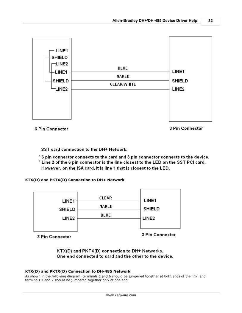
SST card connection to the DH+ Network
32
www.kepware.com
Allen-Bradley DH+/DH-485 Device Driver Help
KTX(D) and PKTX(D) Connection to DH+ Network
KTX(D) and PKTX(D) Connection to DH-485 Network
As shown in the following diagram, terminals 5 and 6 should be jumpered together at both ends of the link, andterminals 1 and 2 should be jumpered together only at one end.
33
www.kepware.com
Allen-Bradley DH+/DH-485 Device Driver Help
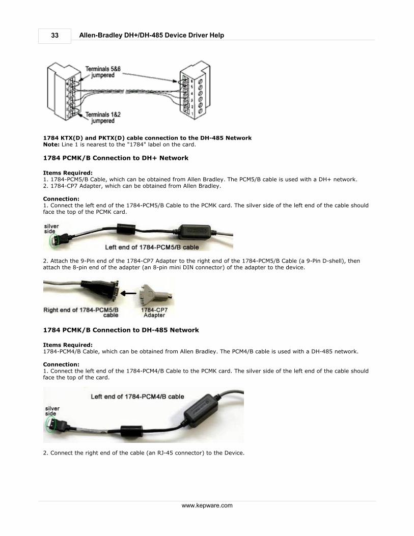
1784 KTX(D) and PKTX(D) cable connection to the DH-485 NetworkNote: Line 1 is nearest to the "1784" label on the card.
1784 PCMK/B Connection to DH+ Network
Items Required:1. 1784-PCM5/B Cable, which can be obtained from Allen Bradley. The PCM5/B cable is used with a DH+ network.2. 1784-CP7 Adapter, which can be obtained from Allen Bradley. Connection:1. Connect the left end of the 1784-PCM5/B Cable to the PCMK card. The silver side of the left end of the cable shouldface the top of the PCMK card.
2. Attach the 9-Pin end of the 1784-CP7 Adapter to the right end of the 1784-PCM5/B Cable (a 9-Pin D-shell), thenattach the 8-pin end of the adapter (an 8-pin mini DIN connector) of the adapter to the device.
1784 PCMK/B Connection to DH-485 Network
Items Required:1784-PCM4/B Cable, which can be obtained from Allen Bradley. The PCM4/B cable is used with a DH-485 network. Connection:1. Connect the left end of the 1784-PCM4/B Cable to the PCMK card. The silver side of the left end of the cable shouldface the top of the card.
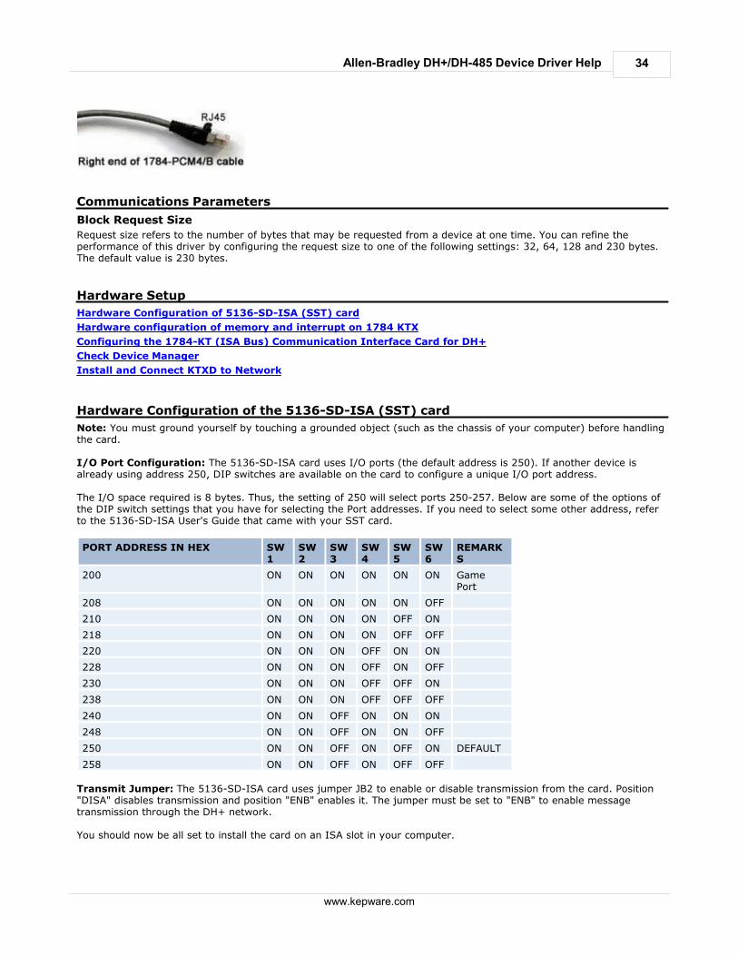
2. Connect the right end of the cable (an RJ-45 connector) to the Device.
34
www.kepware.com
Allen-Bradley DH+/DH-485 Device Driver Help
Communications Parameters
Block Request Size
Request size refers to the number of bytes that may be requested from a device at one time. You can refine theperformance of this driver by configuring the request size to one of the following settings: 32, 64, 128 and 230 bytes.The default value is 230 bytes.
Hardware Setup
Hardware Configuration of 5136-SD-ISA (SST) card
Hardware configuration of memory and interrupt on 1784 KTX
Configuring the 1784-KT (ISA Bus) Communication Interface Card for DH+
Check Device Manager
Install and Connect KTXD to Network
Hardware Configuration of the 5136-SD-ISA (SST) card
Note: You must ground yourself by touching a grounded object (such as the chassis of your computer) before handlingthe card. I/O Port Configuration: The 5136-SD-ISA card uses I/O ports (the default address is 250). If another device isalready using address 250, DIP switches are available on the card to configure a unique I/O port address. The I/O space required is 8 bytes. Thus, the setting of 250 will select ports 250-257. Below are some of the options ofthe DIP switch settings that you have for selecting the Port addresses. If you need to select some other address, referto the 5136-SD-ISA User's Guide that came with your SST card.
PORT ADDRESS IN HEX SW1
SW2
SW3
SW4
SW5
SW6
REMARKS
200 ON ON ON ON ON ON GamePort
208 ON ON ON ON ON OFF
210 ON ON ON ON OFF ON
218 ON ON ON ON OFF OFF
220 ON ON ON OFF ON ON
228 ON ON ON OFF ON OFF
230 ON ON ON OFF OFF ON
238 ON ON ON OFF OFF OFF
240 ON ON OFF ON ON ON
248 ON ON OFF ON ON OFF
250 ON ON OFF ON OFF ON DEFAULT
258 ON ON OFF ON OFF OFF
Transmit Jumper: The 5136-SD-ISA card uses jumper JB2 to enable or disable transmission from the card. Position"DISA" disables transmission and position "ENB" enables it. The jumper must be set to "ENB" to enable messagetransmission through the DH+ network. You should now be all set to install the card on an ISA slot in your computer.
35
www.kepware.com
Allen-Bradley DH+/DH-485 Device Driver Help
Hardware Configuration of Memory and Interrupt on 1784 KTXD card
Select a unique memory address from the range C800-D700 and a unique Interrupt Request Level (IRQ). The Interruptlevels allowed are (3,4,5, and 7). Make sure that the value chosen for the Interrupt is unique by checking the Device Manager.
Memory Configuration
There are two channels on the Allen Bradley 1784-KTX (D) card that you can communicate with (see the CableConnections file for more information). If you are planning to use channel 1, turn the knobs (sw3 and sw4) underChannel 1 to reflect your selected memory address. For example: If you choose address D000, then your sw3 shouldpoint to "D" and sw4 should point to "0." Similarly, if you choose channel 2, turn the knobs (sw1 and sw2) to reflectyour selected memory address.
Interrupt Configuration
If you are using interrupts, you should choose an interrupt level as mentioned above. The KTX (D) card comes with twojumpers. Each jumper is used for selecting the interrupt level for each of the channels. You should place the jumpercorresponding to your chosen channel number, horizontally across the two pins next to your selected interrupt level.For example: if you are using channel 1 and you have selected interrupt level 3, you should place one of the jumpershorizontally across pin 3 under channel number 1. If you are not using interrupts, you should place the jumpervertically, thus connecting pins of two different interrupt levels (such as 3 and 5).
Configuring the 1784-KT (ISA Bus) Communication Interface Card for DH+
Note: Before handling the card, you must ground yourself by touching a grounded object such as the chassis of yourcomputer. Please note the following requirements for the 1784-KT (ISA Bus) card:
The 1784-KT card has a DIP switch configuration which must be configured to match the driver's KT
communications address settings.
The selected address must not conflict with any other address used by your computer.
If you plan to use multiple 1784-KT cards, each one needs to be assigned a unique address.
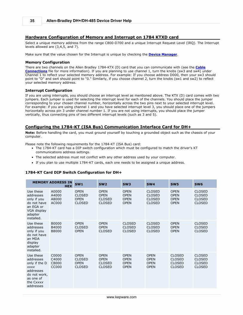
1784-KT Card DIP Switch Configuration for DH+
MEMORY ADDRESS INHEX
SW1 SW2 SW3 SW4 SW5 SW6
Use theseaddressesonly if youdo not havean EGA orVGA displayadapterinstalled.
A0000A4000A8000AC000
OPENCLOSEDOPENCLOSED
OPENOPENCLOSEDCLOSED
OPENOPENOPENOPEN
CLOSEDCLOSEDCLOSEDCLOSED
OPENOPENOPENOPEN
CLOSEDCLOSEDCLOSEDCLOSED
Use theseaddressesonly if youdo not havean MDAdisplayadapterinstalled.
B0000B4000B8000
OPENCLOSEDOPEN
OPENOPENCLOSED
CLOSEDCLOSEDCLOSED
CLOSEDCLOSEDCLOSED
OPENOPENOPEN
CLOSEDCLOSEDCLOSED
Use theseaddressesonly if the Dxxxxaddressesdo not work,as one ofthe Cxxxxaddresses
C0000C4000C8000CC000
OPENCLOSEDOPENCLOSED
OPENOPENCLOSEDCLOSED
OPENOPENOPENOPEN
OPENOPENOPENOPEN
CLOSEDCLOSEDCLOSEDCLOSED
CLOSEDCLOSEDCLOSEDCLOSED
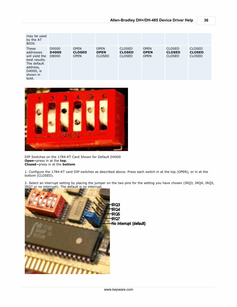
36
www.kepware.com
Allen-Bradley DH+/DH-485 Device Driver Help
may be usedby the ATBIOS.
Theseaddresseswill yield thebest results.The defaultaddress,D4000, isshown inbold.
D0000D4000D8000
OPENCLOSEDOPEN
OPENOPENCLOSED
CLOSEDCLOSEDCLOSED
OPENOPENOPEN
CLOSEDCLOSEDCLOSED
CLOSEDCLOSEDCLOSED
DIP Switches on the 1784-KT Card Shown for Default D4000Open=press in at the top.Closed=press in at the bottom 1. Configure the 1784-KT card DIP switches as described above. Press each switch in at the top (OPEN), or in at thebottom (CLOSED). 2. Select an interrupt setting by placing the jumper on the two pins for the setting you have chosen (IRQ3, IRQ4, IRQ5,IRQ7 or no interrupt). The default is no interrupt.
37
www.kepware.com
Allen-Bradley DH+/DH-485 Device Driver Help
3. Carefully slide the 1784-KT card into the I/O expansion slot. Press firmly until the card is seated in the slot. 4. Install the retaining screw into the retaining bracket.
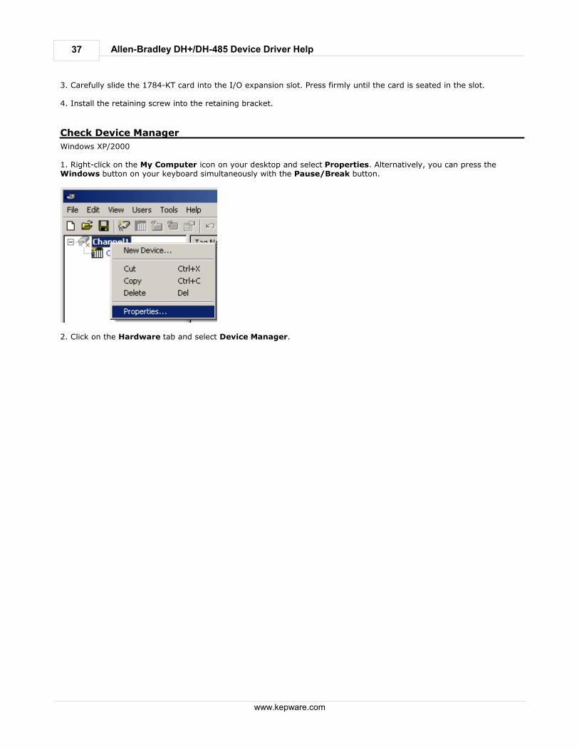
Check Device Manager
Windows XP/2000 1. Right-click on the My Computer icon on your desktop and select Properties. Alternatively, you can press theWindows button on your keyboard simultaneously with the Pause/Break button.
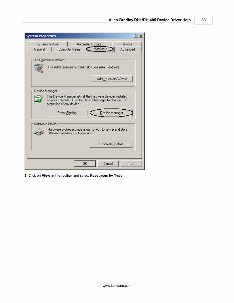
2. Click on the Hardware tab and select Device Manager.
38
www.kepware.com
Allen-Bradley DH+/DH-485 Device Driver Help
3. Click on View in the toolbar and select Resources by Type.
39
www.kepware.com
Allen-Bradley DH+/DH-485 Device Driver Help
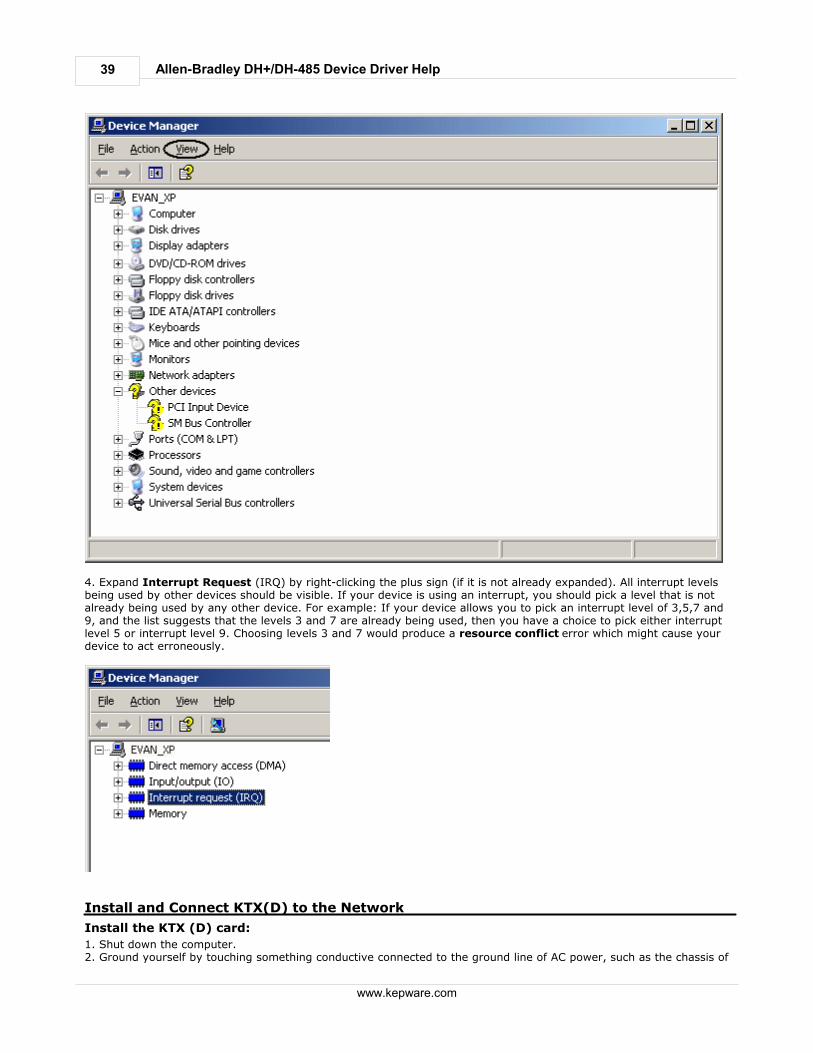
4. Expand Interrupt Request (IRQ) by right-clicking the plus sign (if it is not already expanded). All interrupt levelsbeing used by other devices should be visible. If your device is using an interrupt, you should pick a level that is notalready being used by any other device. For example: If your device allows you to pick an interrupt level of 3,5,7 and9, and the list suggests that the levels 3 and 7 are already being used, then you have a choice to pick either interruptlevel 5 or interrupt level 9. Choosing levels 3 and 7 would produce a resource conflict error which might cause yourdevice to act erroneously.
Install and Connect KTX(D) to the Network
Install the KTX (D) card:
1. Shut down the computer.2. Ground yourself by touching something conductive connected to the ground line of AC power, such as the chassis of
40
www.kepware.com
Allen-Bradley DH+/DH-485 Device Driver Help
the computer while it is plugged to the AC power.3. Insert the card on an available ISA slot. Make sure the card is inserted properly.
Connect the card to the Network:
The KTX (D) has two channels. Channel 2 can have connections to either a DH+ or DH-485 network. Channel 1 canonly connect to DH+. Thus, you can have two different DH+ network connections, or one DH+ and one DH-485network connection to the KTX (D) card.
Modular I/O Selection Guide
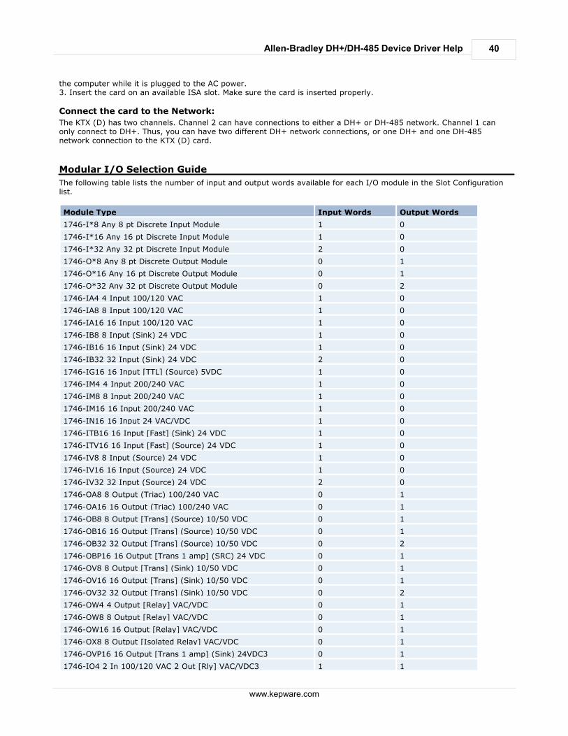
The following table lists the number of input and output words available for each I/O module in the Slot Configurationlist.
Module Type Input Words Output Words
1746-I*8 Any 8 pt Discrete Input Module 1 0
1746-I*16 Any 16 pt Discrete Input Module 1 0
1746-I*32 Any 32 pt Discrete Input Module 2 0
1746-O*8 Any 8 pt Discrete Output Module 0 1
1746-O*16 Any 16 pt Discrete Output Module 0 1
1746-O*32 Any 32 pt Discrete Output Module 0 2
1746-IA4 4 Input 100/120 VAC 1 0
1746-IA8 8 Input 100/120 VAC 1 0
1746-IA16 16 Input 100/120 VAC 1 0
1746-IB8 8 Input (Sink) 24 VDC 1 0
1746-IB16 16 Input (Sink) 24 VDC 1 0
1746-IB32 32 Input (Sink) 24 VDC 2 0
1746-IG16 16 Input [TTL] (Source) 5VDC 1 0
1746-IM4 4 Input 200/240 VAC 1 0
1746-IM8 8 Input 200/240 VAC 1 0
1746-IM16 16 Input 200/240 VAC 1 0
1746-IN16 16 Input 24 VAC/VDC 1 0
1746-ITB16 16 Input [Fast] (Sink) 24 VDC 1 0
1746-ITV16 16 Input [Fast] (Source) 24 VDC 1 0
1746-IV8 8 Input (Source) 24 VDC 1 0
1746-IV16 16 Input (Source) 24 VDC 1 0
1746-IV32 32 Input (Source) 24 VDC 2 0
1746-OA8 8 Output (Triac) 100/240 VAC 0 1
1746-OA16 16 Output (Triac) 100/240 VAC 0 1
1746-OB8 8 Output [Trans] (Source) 10/50 VDC 0 1
1746-OB16 16 Output [Trans] (Source) 10/50 VDC 0 1
1746-OB32 32 Output [Trans] (Source) 10/50 VDC 0 2
1746-OBP16 16 Output [Trans 1 amp] (SRC) 24 VDC 0 1
1746-OV8 8 Output [Trans] (Sink) 10/50 VDC 0 1
1746-OV16 16 Output [Trans] (Sink) 10/50 VDC 0 1
1746-OV32 32 Output [Trans] (Sink) 10/50 VDC 0 2
1746-OW4 4 Output [Relay] VAC/VDC 0 1
1746-OW8 8 Output [Relay] VAC/VDC 0 1
1746-OW16 16 Output [Relay] VAC/VDC 0 1
1746-OX8 8 Output [Isolated Relay] VAC/VDC 0 1
1746-OVP16 16 Output [Trans 1 amp] (Sink) 24VDC3 0 1
1746-IO4 2 In 100/120 VAC 2 Out [Rly] VAC/VDC3 1 1
41
www.kepware.com
Allen-Bradley DH+/DH-485 Device Driver Help
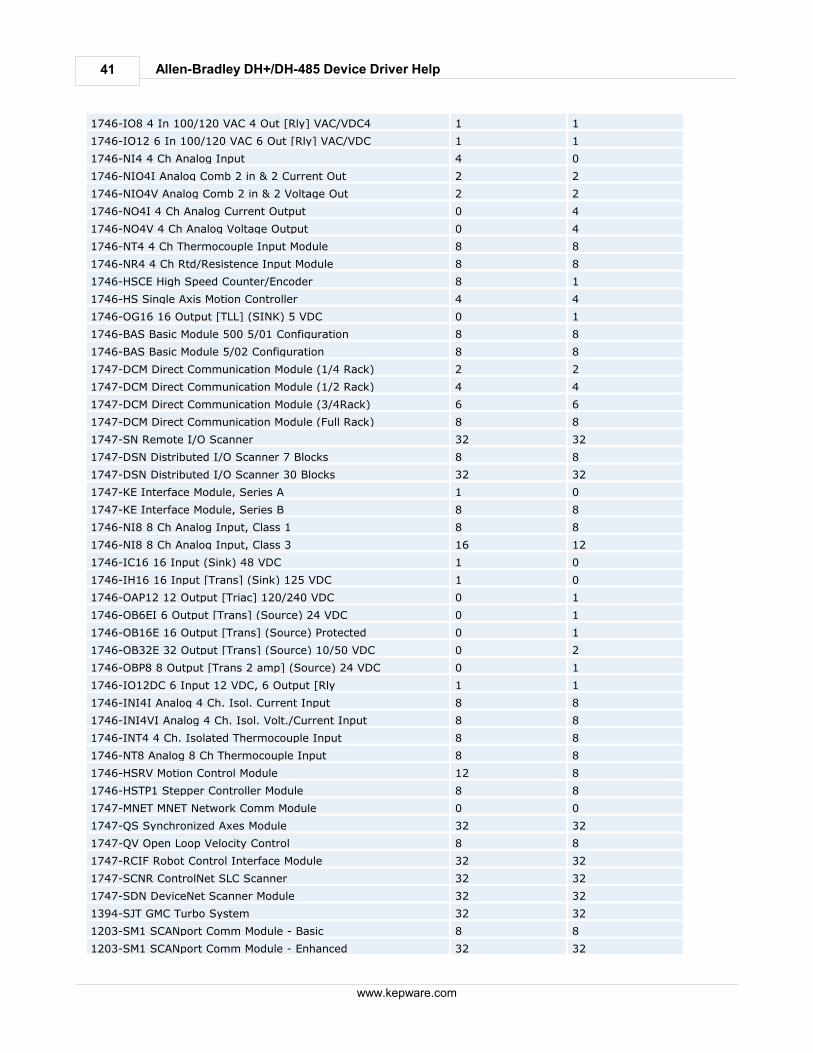
1746-IO8 4 In 100/120 VAC 4 Out [Rly] VAC/VDC4 1 1
1746-IO12 6 In 100/120 VAC 6 Out [Rly] VAC/VDC 1 1
1746-NI4 4 Ch Analog Input 4 0
1746-NIO4I Analog Comb 2 in & 2 Current Out 2 2
1746-NIO4V Analog Comb 2 in & 2 Voltage Out 2 2
1746-NO4I 4 Ch Analog Current Output 0 4
1746-NO4V 4 Ch Analog Voltage Output 0 4
1746-NT4 4 Ch Thermocouple Input Module 8 8
1746-NR4 4 Ch Rtd/Resistence Input Module 8 8
1746-HSCE High Speed Counter/Encoder 8 1
1746-HS Single Axis Motion Controller 4 4
1746-OG16 16 Output [TLL] (SINK) 5 VDC 0 1
1746-BAS Basic Module 500 5/01 Configuration 8 8
1746-BAS Basic Module 5/02 Configuration 8 8
1747-DCM Direct Communication Module (1/4 Rack) 2 2
1747-DCM Direct Communication Module (1/2 Rack) 4 4
1747-DCM Direct Communication Module (3/4Rack) 6 6
1747-DCM Direct Communication Module (Full Rack) 8 8
1747-SN Remote I/O Scanner 32 32
1747-DSN Distributed I/O Scanner 7 Blocks 8 8
1747-DSN Distributed I/O Scanner 30 Blocks 32 32
1747-KE Interface Module, Series A 1 0
1747-KE Interface Module, Series B 8 8
1746-NI8 8 Ch Analog Input, Class 1 8 8
1746-NI8 8 Ch Analog Input, Class 3 16 12
1746-IC16 16 Input (Sink) 48 VDC 1 0
1746-IH16 16 Input [Trans] (Sink) 125 VDC 1 0
1746-OAP12 12 Output [Triac] 120/240 VDC 0 1
1746-OB6EI 6 Output [Trans] (Source) 24 VDC 0 1
1746-OB16E 16 Output [Trans] (Source) Protected 0 1
1746-OB32E 32 Output [Trans] (Source) 10/50 VDC 0 2
1746-OBP8 8 Output [Trans 2 amp] (Source) 24 VDC 0 1
1746-IO12DC 6 Input 12 VDC, 6 Output [Rly 1 1
1746-INI4I Analog 4 Ch. Isol. Current Input 8 8
1746-INI4VI Analog 4 Ch. Isol. Volt./Current Input 8 8
1746-INT4 4 Ch. Isolated Thermocouple Input 8 8
1746-NT8 Analog 8 Ch Thermocouple Input 8 8
1746-HSRV Motion Control Module 12 8
1746-HSTP1 Stepper Controller Module 8 8
1747-MNET MNET Network Comm Module 0 0
1747-QS Synchronized Axes Module 32 32
1747-QV Open Loop Velocity Control 8 8
1747-RCIF Robot Control Interface Module 32 32
1747-SCNR ControlNet SLC Scanner 32 32
1747-SDN DeviceNet Scanner Module 32 32
1394-SJT GMC Turbo System 32 32
1203-SM1 SCANport Comm Module - Basic 8 8
1203-SM1 SCANport Comm Module - Enhanced 32 32
42
www.kepware.com
Allen-Bradley DH+/DH-485 Device Driver Help
AMCI-1561 AMCI Series 1561 Resolver Module 8 8
SLC500 Slot Configuration
Slot Configuration
SLC500 models (modular I/O racks) need to be configured for use with the AB DH+ driver if the I/O is to be accessedby the driver. Up to 30 slots can be configured per device.
To use the slot configuration dialog:
1. Left-click on the row in the Slot/module list box to select the slot to configure.2. Select a module from the Available modules list box by left-clicking on it.3. Finally, click the Add button to add the module. Note: You can remove a module by first selecting the slot in the slot/module list box and then clicking the Removebutton. The available module selections are the same as those in the Allen Bradley APS software. Knowledge of the number of input and output words in each slot is necessary for the driver to correctly address the I/O.Only the number of input and output words in slots (up to the slot of interest) is needed to address I/O in that slot. Forexample, if you are only going to access slot 3, you would have to configure slots 1, 2 and 3. See Also: Modular I/O Selection Guide
Optimizing Your AB Data Highway Communications
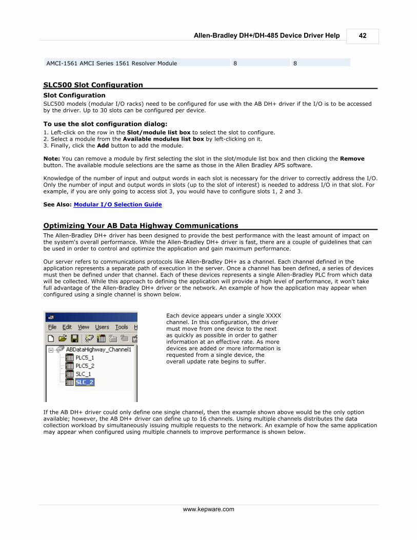
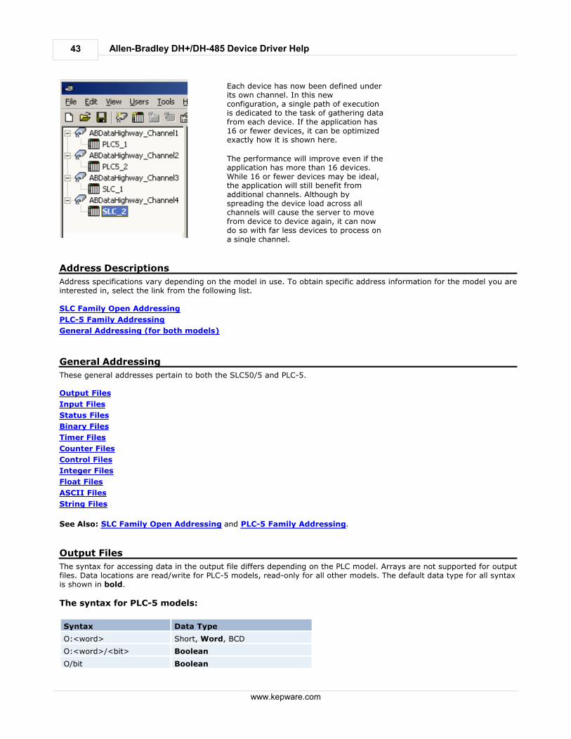
The Allen-Bradley DH+ driver has been designed to provide the best performance with the least amount of impact onthe system's overall performance. While the Allen-Bradley DH+ driver is fast, there are a couple of guidelines that canbe used in order to control and optimize the application and gain maximum performance. Our server refers to communications protocols like Allen-Bradley DH+ as a channel. Each channel defined in theapplication represents a separate path of execution in the server. Once a channel has been defined, a series of devicesmust then be defined under that channel. Each of these devices represents a single Allen-Bradley PLC from which datawill be collected. While this approach to defining the application will provide a high level of performance, it won't takefull advantage of the Allen-Bradley DH+ driver or the network. An example of how the application may appear whenconfigured using a single channel is shown below.
Each device appears under a single XXXXchannel. In this configuration, the drivermust move from one device to the nextas quickly as possible in order to gatherinformation at an effective rate. As moredevices are added or more information isrequested from a single device, theoverall update rate begins to suffer.
If the AB DH+ driver could only define one single channel, then the example shown above would be the only optionavailable; however, the AB DH+ driver can define up to 16 channels. Using multiple channels distributes the datacollection workload by simultaneously issuing multiple requests to the network. An example of how the same applicationmay appear when configured using multiple channels to improve performance is shown below.
43
www.kepware.com
Allen-Bradley DH+/DH-485 Device Driver Help
Each device has now been defined underits own channel. In this newconfiguration, a single path of executionis dedicated to the task of gathering datafrom each device. If the application has16 or fewer devices, it can be optimizedexactly how it is shown here.
The performance will improve even if theapplication has more than 16 devices.While 16 or fewer devices may be ideal,the application will still benefit fromadditional channels. Although byspreading the device load across allchannels will cause the server to movefrom device to device again, it can nowdo so with far less devices to process ona single channel.
Address Descriptions
Address specifications vary depending on the model in use. To obtain specific address information for the model you areinterested in, select the link from the following list. SLC Family Open Addressing
PLC-5 Family Addressing
General Addressing (for both models)
General Addressing
These general addresses pertain to both the SLC50/5 and PLC-5. Output Files
Input Files
Status Files
Binary Files
Timer Files
Counter Files
Control Files
Integer Files
Float Files
ASCII Files
String Files
See Also: SLC Family Open Addressing and PLC-5 Family Addressing.
Output Files
The syntax for accessing data in the output file differs depending on the PLC model. Arrays are not supported for outputfiles. Data locations are read/write for PLC-5 models, read-only for all other models. The default data type for all syntaxis shown in bold.
The syntax for PLC-5 models:
Syntax Data Type
O:<word> Short, Word, BCD
O:<word>/<bit> Boolean
O/bit Boolean
44
www.kepware.com
Allen-Bradley DH+/DH-485 Device Driver Help
Note: Word and bit address information is in octal for PLC-5 models. This follows the convention of the programmingsoftware.
The syntax for SLC Family Open models (modular I/O):
Syntax Data Type
O:<slot> Short, Word, BCD
O:<slot>.<word> Short, Word, BCD
O:<slot>/<bit> Boolean
O:<slot>.<word>/<bit> Boolean
The following slot and word locations are allowed for each model.
PLC Model Min Slot Max Slot Max Word
SLC Family 1 30 *
PLC-5 Family NA NA 277 (octal)
*The number of Input or Output words available for each I/O module can be found in the Modular I/O SelectionGuide. For slot configuration help see the Device Setup page of this help file.
Examples
PLC-5 Addresses are in octal
O:0 word 0
O:37 word 31 (37 octal=31 decimal)
O/42 bit 34 (42 octal=34 decimal)
O:2/2 bit 2 word 2 (same as O/42)
SLC Family
O:1 word 0 slot 1
O:1.0 word 0 slot 1 (same as O:1)
O:12 word 0 slot 12
O:12.2 word 2 slot 12
O:4.0/0 bit 0 word 0 slot 4
O:4/0 bit 0 slot 4 (same as O:4.0/0)
O:4.2/0 bit 0 word 2 slot 4
O:4/32 bit 32 slot 4 (same as O:4.2/0)
Input Files
The syntax for accessing data in the input file differs depending on the PLC model. Arrays are not supported for inputfiles. Data locations are Read/Write for PLC-5 models, Read Only for all other models. The default data type for allsyntax is shown in bold.
The syntax for PLC-5 models:
Syntax Data Type
I:<word> Short, Word, BCD
I:<word>/<bit> Boolean
I/bit Boolean
Note: Word and bit address information is in octal for PLC-5 models. This follows the convention of the programmingsoftware.
45
www.kepware.com
Allen-Bradley DH+/DH-485 Device Driver Help
The syntax for SLC Family Open models (modular I/O):
Syntax Data Type
I:<slot> Short, Word, BCD
I:<slot>.<word> Short, Word, BCD
I:<slot>/<bit> Boolean
I:<slot>.<word>/<bit> Boolean
The following slot and word locations are allowed for each model.
PLC Model Min Slot Max Slot Max Word
SLC 5/05 1 30 *
PLC5 Family NA NA 277 (octal)
*The number of Input or Output words available for each I/O module can be found in the Modular I/O SelectionGuide. For slot configuration help, refer to Device Setup.
Examples
PLC-5 Addresses are in octal
I:0 word 0
I:10 word 8 (10 octal=8 decimal)
I/20 bit 16 (20 octal=16 decimal)
I:1/0 bit 0 word 1 (same as I/20)
SLC Family
I:1 word 0 slot 1
I:1.0 word 0 slot 1 (same as I:1)
I:12 word 0 slot 12
I:12.2 word 2 slot 12
I:4.0/0 bit 0 word 0 slot 4
I:4/0 bit 0 slot 4 (same as I:4.0/0)
I:4.2/0 bit 0 word 2 slot 4
I:4/32 bit 32 slot 4 (same as I:4.2/0)
Binary Files
The syntax for accessing a binary file is to specify a file number, a word and (optionally) a bit within the word. Thedefault data type for all syntax is shown in bold.
Syntax Data Type
B<file>:<word> Short, Word, BCD, DWord, Long, LBCD
B<file>:<word> [rows][cols] Short, Word, BCD, DWord, Long, LBCD (array types)
B<file>:<word> [cols] Short, Word, BCD, DWord, Long, LBCD (array types)
B<file>:<word>/<bit> Boolean
B<file>/bit Boolean
The number of array elements (in bytes) cannot exceed the block request size specified. This means that array sizecannot exceed 16 words given a block request size of 32 bytes. The following file numbers and maximum word locations are allowed for each model. The maximum word location isone less when accessing as a 32 bit data type (Long, DWord or Long BCD).
46
www.kepware.com
Allen-Bradley DH+/DH-485 Device Driver Help
PLC Model File Number Max Word
SLC 5/05 Open 3, 9-999 999
PLC-5 Family 3-999 1999
Example Description
B3:0 word 0
B3/26 bit 26
B12:4/15 bit 15 word 4
B3:10 [20] 20 element array starting at word 10
B15:0 [6] [6] 6 by 6 element array starting at word 0
Status Files
The syntax for accessing a status file is to specify a word and (optionally) a bit within the word. The default data typefor all syntax is shown in bold.
Syntax Data Type
S:<word> Short, Word, BCD, DWord, Long, LBCD
S:<word> [rows][cols] Short, Word, BCD, DWord, Long, LBCD (array types)
S:<word> [cols] Short, Word, BCD, DWord, Long, LBCD (array types)
S:<word>/<bit> Boolean
S/bit Boolean
The number of array elements (in bytes) cannot exceed the block request size specified. This means that array sizecannot exceed 16 words given a block request size of 32 bytes. The following word locations are allowed for each model. The maximum word location is one less when accessing as a32 bit data type (Long, DWord or Long BCD).
PLC Model Max Word
SLC Family 999
PLC-5 Family 999
Example Description
S:0 word 0
S/26 bit 26
S:4/15 bit 15 word 4
S:10 [16] 16 element array starting at word 10
S:0 [4] [8] 4 by 8 element array starting at word 0
Timer Files
Timer files are a structured type whose data is accessed by specifying a file number, an element and a field. The defaultdata type depends on the field being accessed. Integer fields receive a default data type of Word.
Syntax Data Type
T<file>:<element>.<field> Depends on field
The following file numbers and maximum element are allowed for each model.
PLC Model File Number Max Element
SLC Family 4, 9-999 999
PLC-5 Family 3-999 1999
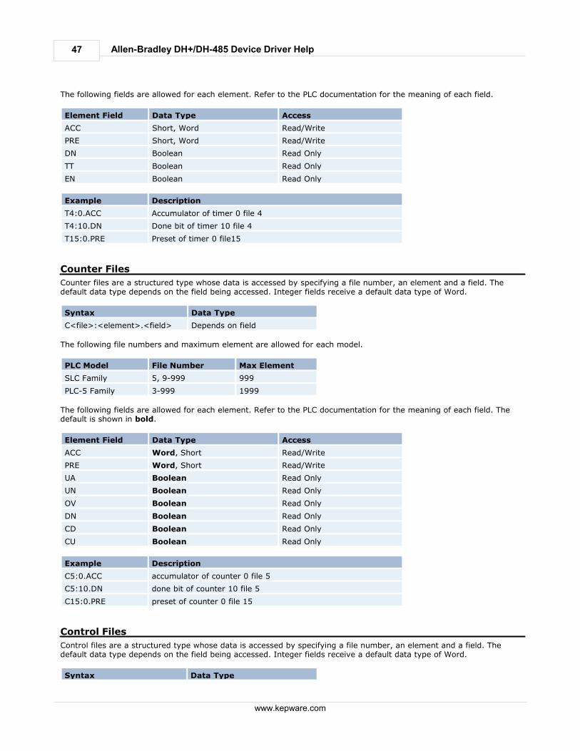
47
www.kepware.com
Allen-Bradley DH+/DH-485 Device Driver Help
The following fields are allowed for each element. Refer to the PLC documentation for the meaning of each field.
Element Field Data Type Access
ACC Short, Word Read/Write
PRE Short, Word Read/Write
DN Boolean Read Only
TT Boolean Read Only
EN Boolean Read Only
Example Description
T4:0.ACC Accumulator of timer 0 file 4
T4:10.DN Done bit of timer 10 file 4
T15:0.PRE Preset of timer 0 file15
Counter Files
Counter files are a structured type whose data is accessed by specifying a file number, an element and a field. Thedefault data type depends on the field being accessed. Integer fields receive a default data type of Word.
Syntax Data Type
C<file>:<element>.<field> Depends on field
The following file numbers and maximum element are allowed for each model.
PLC Model File Number Max Element
SLC Family 5, 9-999 999
PLC-5 Family 3-999 1999
The following fields are allowed for each element. Refer to the PLC documentation for the meaning of each field. Thedefault is shown in bold.
Element Field Data Type Access
ACC Word, Short Read/Write
PRE Word, Short Read/Write
UA Boolean Read Only
UN Boolean Read Only
OV Boolean Read Only
DN Boolean Read Only
CD Boolean Read Only
CU Boolean Read Only
Example Description
C5:0.ACC accumulator of counter 0 file 5
C5:10.DN done bit of counter 10 file 5
C15:0.PRE preset of counter 0 file 15
Control Files
Control files are a structured type whose data is accessed by specifying a file number, an element and a field. Thedefault data type depends on the field being accessed. Integer fields receive a default data type of Word.
Syntax Data Type
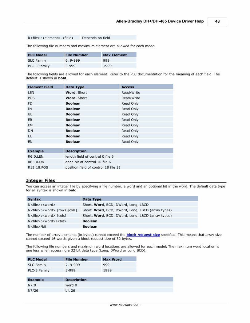
48
www.kepware.com
Allen-Bradley DH+/DH-485 Device Driver Help
R<file>:<element>.<field> Depends on field
The following file numbers and maximum element are allowed for each model.
PLC Model File Number Max Element
SLC Family 6, 9-999 999
PLC-5 Family 3-999 1999
The following fields are allowed for each element. Refer to the PLC documentation for the meaning of each field. Thedefault is shown in bold.
Element Field Data Type Access
LEN Word, Short Read/Write
POS Word, Short Read/Write
FD Boolean Read Only
IN Boolean Read Only
UL Boolean Read Only
ER Boolean Read Only
EM Boolean Read Only
DN Boolean Read Only
EU Boolean Read Only
EN Boolean Read Only
Example Description
R6:0.LEN length field of control 0 file 6
R6:10.DN done bit of control 10 file 6
R15:18.POS position field of control 18 file 15
Integer Files
You can access an integer file by specifying a file number, a word and an optional bit in the word. The default data typefor all syntax is shown in bold.
Syntax Data Type
N<file>:<word> Short, Word, BCD, DWord, Long, LBCD
N<file>:<word> [rows][cols] Short, Word, BCD, DWord, Long, LBCD (array types)
N<file>:<word> [cols] Short, Word, BCD, DWord, Long, LBCD (array types)
N<file>:<word>/<bit> Boolean
N<file>/bit Boolean
The number of array elements (in bytes) cannot exceed the block request size specified. This means that array sizecannot exceed 16 words given a block request size of 32 bytes. The following file numbers and maximum word locations are allowed for each model. The maximum word location isone less when accessing a 32 bit data type (Long, DWord or Long BCD).
PLC Model File Number Max Word
SLC Family 7, 9-999 999
PLC-5 Family 3-999 1999
Example Description
N7:0 word 0
N7/26 bit 26
49
www.kepware.com
Allen-Bradley DH+/DH-485 Device Driver Help
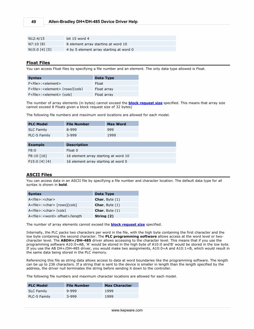
N12:4/15 bit 15 word 4
N7:10 [8] 8 element array starting at word 10
N15:0 [4] [5] 4 by 5 element array starting at word 0
Float Files
You can access Float files by specifying a file number and an element. The only data type allowed is Float.
Syntax Data Type
F<file>:<element> Float
F<file>:<element> [rows][cols] Float array
F<file>:<element> [cols] Float array
The number of array elements (in bytes) cannot exceed the block request size specified. This means that array sizecannot exceed 8 Floats given a block request size of 32 bytes) The following file numbers and maximum word locations are allowed for each model.
PLC Model File Number Max Word
SLC Family 8-999 999
PLC-5 Family 3-999 1999
Example Description
F8:0 Float 0
F8:10 [16] 16 element array starting at word 10
F15:0 [4] [4] 16 element array starting at word 0
ASCII Files
You can access data in an ASCII file by specifying a file number and character location. The default data type for allsyntax is shown in bold.
Syntax Data Type
A<file>:<char> Char, Byte (1)
A<file>:<char> [rows][cols] Char, Byte (1)
A<file>:<char> [cols] Char, Byte (1)
A<file>:<word> offset>/length String (2)
The number of array elements cannot exceed the block request size specified. Internally, the PLC packs two characters per word in the file, with the high byte containing the first character and thelow byte containing the second character. The PLC programming software allows access at the word level or two-character level. The ABDH+/DH-485 driver allows accessing to the character level. This means that if you use theprogramming software A10:0=AB, 'A' would be stored in the high byte of A10:0 and'B' would be stored in the low byte.If you use the AB DH+/DH-485 driver, you would make two assignments, A10:0=A and A10:1=B, which would result inthe same data being stored in the PLC memory. Referencing this file as string data allows access to data at word boundaries like the programming software. The lengthcan be up to 236 characters. If a string that is sent to the device is smaller in length than the length specified by theaddress, the driver null terminates the string before sending it down to the controller. The following file numbers and maximum character locations are allowed for each model.
PLC Model File Number Max Character
SLC Family 9-999 1999
PLC-5 Family 3-999 1999
50
www.kepware.com
Allen-Bradley DH+/DH-485 Device Driver Help
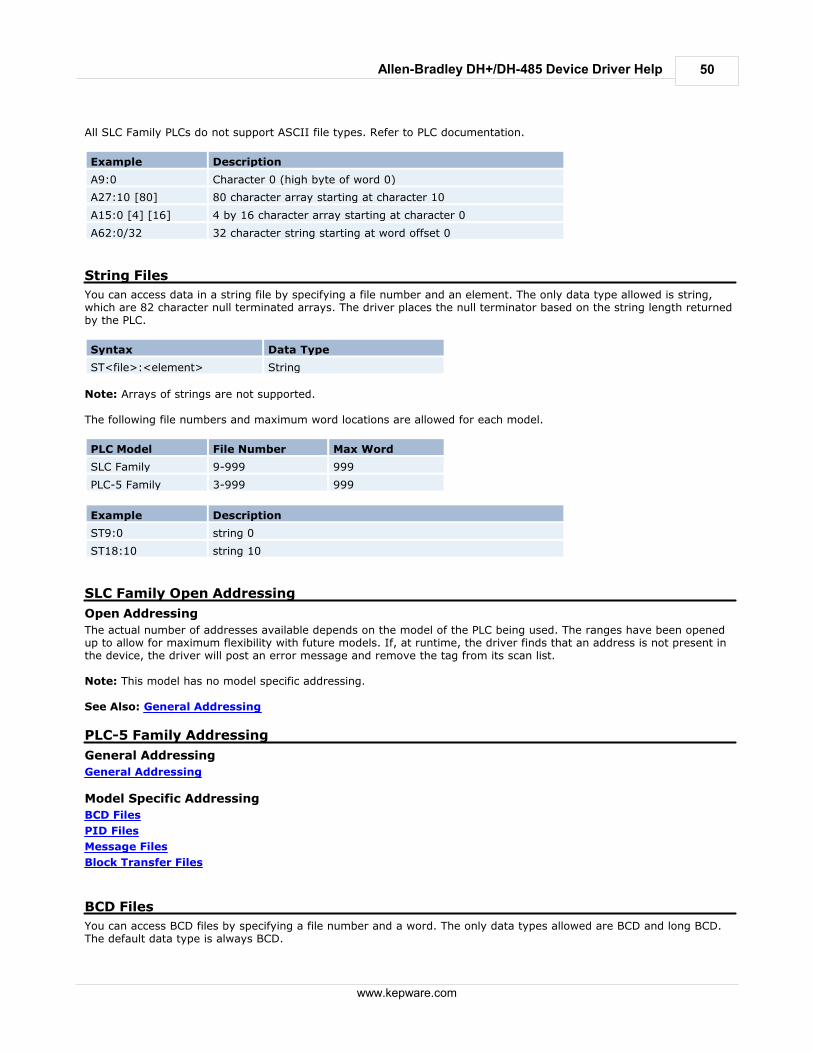
All SLC Family PLCs do not support ASCII file types. Refer to PLC documentation.
Example Description
A9:0 Character 0 (high byte of word 0)
A27:10 [80] 80 character array starting at character 10
A15:0 [4] [16] 4 by 16 character array starting at character 0
A62:0/32 32 character string starting at word offset 0
String Files
You can access data in a string file by specifying a file number and an element. The only data type allowed is string,which are 82 character null terminated arrays. The driver places the null terminator based on the string length returnedby the PLC.
Syntax Data Type
ST<file>:<element> String
Note: Arrays of strings are not supported. The following file numbers and maximum word locations are allowed for each model.
PLC Model File Number Max Word
SLC Family 9-999 999
PLC-5 Family 3-999 999
Example Description
ST9:0 string 0
ST18:10 string 10
SLC Family Open Addressing
Open Addressing
The actual number of addresses available depends on the model of the PLC being used. The ranges have been openedup to allow for maximum flexibility with future models. If, at runtime, the driver finds that an address is not present inthe device, the driver will post an error message and remove the tag from its scan list. Note: This model has no model specific addressing. See Also: General Addressing
PLC-5 Family Addressing
General Addressing
General Addressing
Model Specific Addressing
BCD Files
PID Files
Message Files
Block Transfer Files
BCD Files
You can access BCD files by specifying a file number and a word. The only data types allowed are BCD and long BCD.The default data type is always BCD.
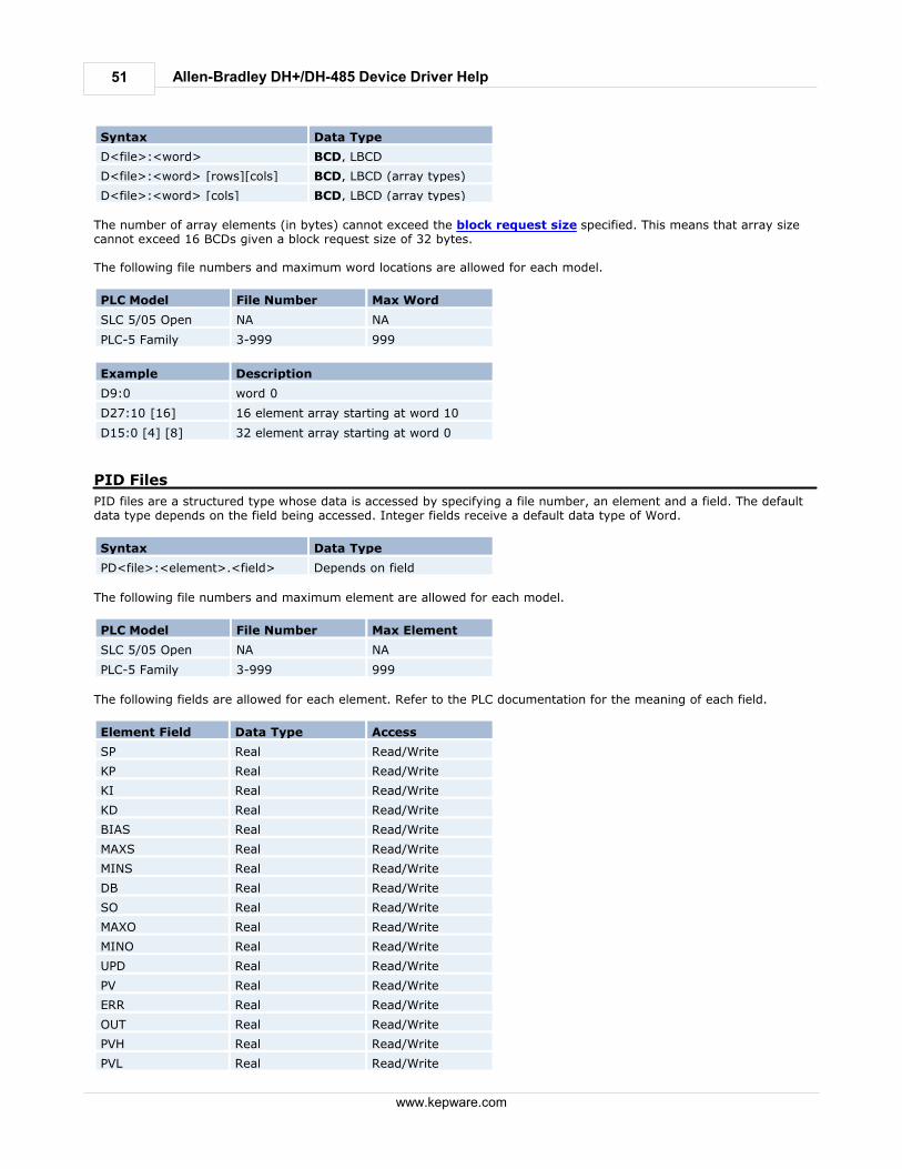
51
www.kepware.com
Allen-Bradley DH+/DH-485 Device Driver Help
Syntax Data Type
D<file>:<word> BCD, LBCD
D<file>:<word> [rows][cols] BCD, LBCD (array types)
D<file>:<word> [cols] BCD, LBCD (array types)
The number of array elements (in bytes) cannot exceed the block request size specified. This means that array sizecannot exceed 16 BCDs given a block request size of 32 bytes. The following file numbers and maximum word locations are allowed for each model.
PLC Model File Number Max Word
SLC 5/05 Open NA NA
PLC-5 Family 3-999 999
Example Description
D9:0 word 0
D27:10 [16] 16 element array starting at word 10
D15:0 [4] [8] 32 element array starting at word 0
PID Files
PID files are a structured type whose data is accessed by specifying a file number, an element and a field. The defaultdata type depends on the field being accessed. Integer fields receive a default data type of Word.
Syntax Data Type
PD<file>:<element>.<field> Depends on field
The following file numbers and maximum element are allowed for each model.
PLC Model File Number Max Element
SLC 5/05 Open NA NA
PLC-5 Family 3-999 999
The following fields are allowed for each element. Refer to the PLC documentation for the meaning of each field.
Element Field Data Type Access
SP Real Read/Write
KP Real Read/Write
KI Real Read/Write
KD Real Read/Write
BIAS Real Read/Write
MAXS Real Read/Write
MINS Real Read/Write
DB Real Read/Write
SO Real Read/Write
MAXO Real Read/Write
MINO Real Read/Write
UPD Real Read/Write
PV Real Read/Write
ERR Real Read/Write
OUT Real Read/Write
PVH Real Read/Write
PVL Real Read/Write
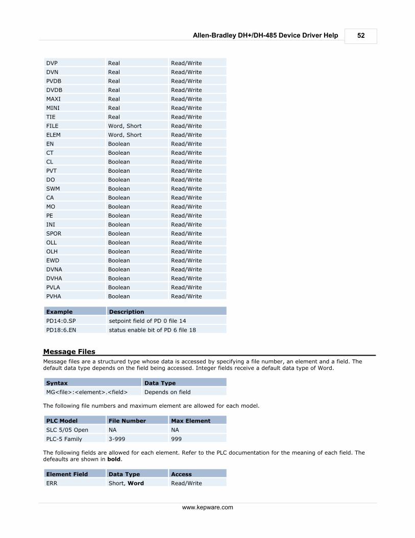
52
www.kepware.com
Allen-Bradley DH+/DH-485 Device Driver Help
DVP Real Read/Write
DVN Real Read/Write
PVDB Real Read/Write
DVDB Real Read/Write
MAXI Real Read/Write
MINI Real Read/Write
TIE Real Read/Write
FILE Word, Short Read/Write
ELEM Word, Short Read/Write
EN Boolean Read/Write
CT Boolean Read/Write
CL Boolean Read/Write
PVT Boolean Read/Write
DO Boolean Read/Write
SWM Boolean Read/Write
CA Boolean Read/Write
MO Boolean Read/Write
PE Boolean Read/Write
INI Boolean Read/Write
SPOR Boolean Read/Write
OLL Boolean Read/Write
OLH Boolean Read/Write
EWD Boolean Read/Write
DVNA Boolean Read/Write
DVHA Boolean Read/Write
PVLA Boolean Read/Write
PVHA Boolean Read/Write
Example Description
PD14:0.SP setpoint field of PD 0 file 14
PD18:6.EN status enable bit of PD 6 file 18
Message Files
Message files are a structured type whose data is accessed by specifying a file number, an element and a field. Thedefault data type depends on the field being accessed. Integer fields receive a default data type of Word.
Syntax Data Type
MG<file>:<element>.<field> Depends on field
The following file numbers and maximum element are allowed for each model.
PLC Model File Number Max Element
SLC 5/05 Open NA NA
PLC-5 Family 3-999 999
The following fields are allowed for each element. Refer to the PLC documentation for the meaning of each field. Thedefeaults are shown in bold.
Element Field Data Type Access
ERR Short, Word Read/Write
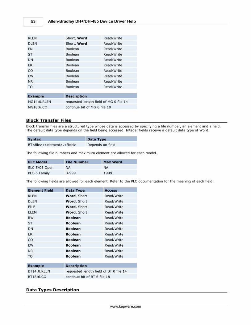
53
www.kepware.com
Allen-Bradley DH+/DH-485 Device Driver Help
RLEN Short, Word Read/Write
DLEN Short, Word Read/Write
EN Boolean Read/Write
ST Boolean Read/Write
DN Boolean Read/Write
ER Boolean Read/Write
CO Boolean Read/Write
EW Boolean Read/Write
NR Boolean Read/Write
TO Boolean Read/Write
Example Description
MG14:0.RLEN requested length field of MG 0 file 14
MG18:6.CO continue bit of MG 6 file 18
Block Transfer Files
Block transfer files are a structured type whose data is accessed by specifying a file number, an element and a field.The default data type depends on the field being accessed. Integer fields receive a default data type of Word.
Syntax Data Type
BT<file>:<element>.<field> Depends on field
The following file numbers and maximum element are allowed for each model.
PLC Model File Number Max Word
SLC 5/05 Open NA NA
PLC-5 Family 3-999 1999
The following fields are allowed for each element. Refer to the PLC documentation for the meaning of each field.
Element Field Data Type Access
RLEN Word, Short Read/Write
DLEN Word, Short Read/Write
FILE Word, Short Read/Write
ELEM Word, Short Read/Write
RW Boolean Read/Write
ST Boolean Read/Write
DN Boolean Read/Write
ER Boolean Read/Write
CO Boolean Read/Write
EW Boolean Read/Write
NR Boolean Read/Write
TO Boolean Read/Write
Example Description
BT14:0.RLEN requested length field of BT 0 file 14
BT18:6.CO continue bit of BT 6 file 18
Data Types Description
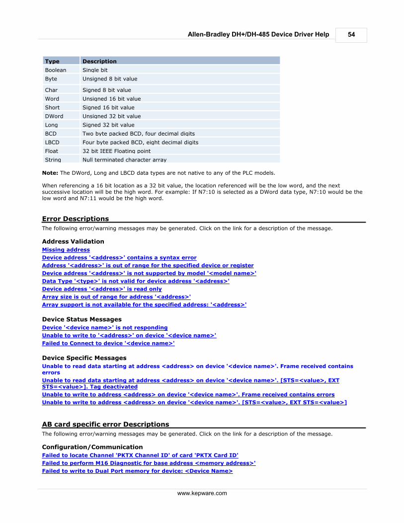
54
www.kepware.com
Allen-Bradley DH+/DH-485 Device Driver Help
Type Description
Boolean Single bit
Byte Unsigned 8 bit value
Char Signed 8 bit value
Word Unsigned 16 bit value
Short Signed 16 bit value
DWord Unsigned 32 bit value
Long Signed 32 bit value
BCD Two byte packed BCD, four decimal digits
LBCD Four byte packed BCD, eight decimal digits
Float 32 bit IEEE Floating point
String Null terminated character array
Note: The DWord, Long and LBCD data types are not native to any of the PLC models. When referencing a 16 bit location as a 32 bit value, the location referenced will be the low word, and the nextsuccessive location will be the high word. For example: If N7:10 is selected as a DWord data type, N7:10 would be thelow word and N7:11 would be the high word.
Error Descriptions
The following error/warning messages may be generated. Click on the link for a description of the message.
Address Validation
Missing address
Device address '<address>' contains a syntax error
Address '<address>' is out of range for the specified device or register
Device address '<address>' is not supported by model '<model name>'
Data Type '<type>' is not valid for device address '<address>'
Device address '<address>' is read only
Array size is out of range for address '<address>'
Array support is not available for the specified address: '<address>'
Device Status Messages
Device '<device name>' is not responding
Unable to write to '<address>' on device '<device name>'
Failed to Connect to device '<device name>'
Device Specific Messages
Unable to read data starting at address <address> on device '<device name>'. Frame received containserrors
Unable to read data starting at address <address> on device '<device name>'. [STS=<value>, EXTSTS=<value>]. Tag deactivated
Unable to write to address <address> on device '<device name>'. Frame received contains errors
Unable to write to address <address> on device '<device name>'. [STS=<value>, EXT STS=<value>]
AB card specific error Descriptions
The following error/warning messages may be generated. Click on the link for a description of the message.
Configuration/Communication
Failed to locate Channel 'PKTX Channel ID' of card 'PKTX Card ID'
Failed to perform M16 Diagnostic for base address <memory address>'
Failed to write to Dual Port memory for device: <Device Name>
55
www.kepware.com
Allen-Bradley DH+/DH-485 Device Driver Help
Failed to clear dual port memory while performing functionality test
Failed RAM test for device: <Device Name>
Failed CTC test for device <Device Name>
Failed SIO test for device: <Device Name>
Failed to open binary file <File Name> for device <Device Name>
Failed to enable card for device : <Device Name>
Failed to perform M16 Key write for device, <Device Name>
Failed to load KTXPCL.BIN on device, <Device Name>
Failed to complete diagnosis while performing M16 Diagnosis for device <Device Name>
Failed to complete loading protocol file while performing M16 diagnosis for device <Device name>
Failed to load binary resource <ResourceID> for device <Device Name>
Failed to allocate device for board '<channel>'
Error performing diagnostics test on channel
SST specific error Descriptions
The following error/warning messages may be generated. Click on the link for a description of the message.
Communication
Duplicate Station ID detected by Device <Device Name>
Invalid Station ID detected by device <Device Name>
Error writing to SST ports for device <Device Name>
Failed to take the SST card offline for device <Device Name>
Bad port/memory detected on SST card while loading module on device <Device Name>
Protocol is not reflected onto memory after being loaded on device <Device Name>
SST module could not be loaded because of a card error on device <Device Name>
SST card execution error occurred on device <Device Name>
Failed to allocate device for board '<channel>'
Missing address
Error Type:
Warning
Possible Cause:
A tag address that has been specified dynamically has no length.
Solution:
Re-enter the address in the client application.
Device address '<address>' contains a syntax error
Error Type:
Warning
Possible Cause:
A tag address that has been specified dynamically contains one or more invalid characters.
Solution:
Re-enter the address in the client application.
Address '<address>' is out of range for the specified device or register
Error Type:
Warning
56
www.kepware.com
Allen-Bradley DH+/DH-485 Device Driver Help
Possible Cause:
A tag address that has been specified dynamically references a location that is beyond the range of supported locationsfor the device.
Solution:
Verify the address is correct; if it is not, re-enter it in the client application.
Device address '<address>' is not supported by model '<model name>'
Error Type:
Warning
Possible Cause:
A tag address that has been specified dynamically references a location that is valid for the communications protocolbut not supported by the target device.
Solution:
Verify that the address is correct; if it is not, re-enter it in the client application. Also verify that the selected modelname for the device is correct.
Data Type '<type>' is not valid for device address '<address>'
Error Type:
Warning
Possible Cause:
A tag address that has been specified dynamically has been assigned an invalid data type.
Solution:
Modify the requested data type in the client application.
Device address '<address>' is read only
Error Type:
Warning
Possible Cause:
A tag address that has been specified dynamically has a requested access mode that is not compatible with what thedevice supports for that address.
Solution:
Change the access mode in the client application.
Array size is out of range for address '<address>'
Error Type:
Warning
Possible Cause:
A tag address that has been specified dynamically is requesting an array size that is too large for the address type orblock size of the driver.
Solution:
Re-enter the address in the client application to specify a smaller value for the array or a different starting point.
57
www.kepware.com
Allen-Bradley DH+/DH-485 Device Driver Help
Array support is not available for the specified address: '<address>'
Error Type:
Warning
Possible Cause:
A tag address that has been specified dynamically contains an array reference for an address type that doesn't supportarrays.
Solution:
Re-enter the address in the client application to remove the array reference or correct the address type.
File Corruption
Error Type:
Fatal
Possible Cause:
One or more binary files that came with your driver may have been corrupted.
Solution:
Contact Technical Support.
Interrupt not configured
Error Type:
Fatal
Possible Cause:
1. The interrupt may not be configured on the device.2. The interrupt configured on the device may not match with the one selected in Channel setup.
Solution:
1. Enable the interrupt by setting the correct jumper/DIP switch combination.2. Set the interrupt parameter on the chanel properties matching the one set up on the card.
Device '<device name>' is not responding
Error Type:
Warning
Possible Cause:
1. The connection between the card and the device may be broken.2. The connection between the PC and the card may be broken.3. The card may have been loaded with an incorrect protocol.4. The named device may have been assigned an incorrect memory address.5. The channel may have been set up incorrectly.
Solution:
1. Verify that the card is inserted correctly onto the right slot.2. Verify the Device ID given to the named device matches that of the actual device.3. Make sure the channel settings (such as baud rate, card type and etc.) match that of your card and device settings.
Unable to write to '<address>' on device '<device name>'
Error Type:
Warning
58
www.kepware.com
Allen-Bradley DH+/DH-485 Device Driver Help
Possible Cause:
1. The connection between the device and the card is broken.2. The connection between the host PC and the card is broken.3. The card may have been loaded with incorrect module.
Solution:
1. Verify the cabling between the device and the card.2. Verify that the card is inserted properly onto the right slot.3. Verify that all the parameters (card, memory address, I/O port, etc) are correctly chosen while creating the project.
Failed to connect to device '<device name>'
Error Type:
Fatal
Possible Cause:
1. The card may not have been installed correctly.2. An inappropriate "inf" file may have been loaded for this device.
Solution:
1. Verify that all the card pins are comfortably connected to the slot.2. Go to Device Manager and make sure you do not have the wrong driver installed for this device.
Unable to read data starting at address <address> on device '<device name>'.[STS=<value>, EXT STS=<value>]. Tag deactivated
Error Type:
Warning
Possible Cause:
The address requested in the block does not exist in the PLC.
Solution:
Check the status and extended status codes that are being returned by the PLC. Note that an extended status code maynot always be returned and thus the error information is contained within the status code. The codes are displayed inhexadecimal. Status code errors in the low nibble of the status code indicate errors found by the local node. The driver will continueto retry reading these blocks of data periodically. Errors found by the local node occur when the KF module cannot seethe destination PLC on the network for some reason. Status code errors in the high nibble of the status code indicate errors found by the PLC. These errors are generatedwhen the block of data the driver is asking for is not available in the PLC. The driver will not ask for these blocks againafter receiving this kind of error. This kind of error can be generated if the address does not exist in the PLC.
Note:
The block starting at address <address> may be deactivated in the process depending on the severity of the error. Theerror message will state this as it does above.
Unable to write to address <address> on device '<device name>'. [STS=<value>, EXTSTS=<value>]
Error Type:
Warning
Possible Cause:
The address written to does not exist in the PLC.
Solution:

59
www.kepware.com
Allen-Bradley DH+/DH-485 Device Driver Help
1. Check the status and extended status codes that are being returned by the PLC. Note that an extended status codemay not always be returned and thus the error information is contained within the status code. The codes are displayedin hexadecimal.2. Status code errors in the low nibble of the status code indicate errors found by the local node. Errors found by thelocal node occur when the card cannot see the destination PLC on the network for some reason.3. Status code errors in the high nibble of the status code indicate errors found by the PLC. These errors are generatedwhen the data location is not available in the PLC or not write able.
Unable to write to address <address> on device '<device name>'. Frame receivedcontains errors
Error Type:
Warning
The Error Could Be:
1. Incorrect frame size received.2. TNS mismatch.3. Invalid response command returned from device.
Possible Cause:
1. Misalignment of packets due to connection/disconnection between PC and device.2. There is bad cabling connecting the devices causing noise.
Solution:
The driver will recover from this error without intervention. If this error occurs frequently, there may be an issue withthe cabling or the device itself.
Failed RAM, CTC or SIO Test
Error Type:
Fatal
Possible Cause:
1. Memory Conflict.2. Temporary network problem.3. Bad memory address selected.4. The parameters selected for Channel setup may be incorrect.5. Card Corrupted.
Solution:
1. Some other device may be using the same memory address. Configure the device with a different memory address.2. Restart the driver.3. The memory address selected is not within the range: try a different memory address.4. Modify the channel properties with appropriate values.5. Replace the card.
Failed to complete diagnosis while performing M16 Diagnosis
Error Type:
Fatal
Possible Cause:
You should only see this error when one of the following error occurs. Click on the errors to review the possiblesolutions. Failed to perform M16 Diagnostic for base address <memory address>'
Failed to perform M16 Key write for device, <Device Name>
Failed to complete loading protocol file while performing M16 diagnosis for device <Device name>
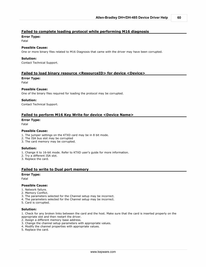
60
www.kepware.com
Allen-Bradley DH+/DH-485 Device Driver Help
Failed to complete loading protocol while performing M16 diagnosis
Error Type:
Fatal
Possible Cause:
One or more binary files related to M16 Diagnosis that came with the driver may have been corrupted.
Solution:
Contact Technical Support.
Failed to load binary resource <ResourceID> for device <Device>
Error Type:
Fatal
Possible Cause:
One of the binary files required for loading the protocol may be corrupted.
Solution:
Contact Technical Support.
Failed to perform M16 Key Write for device <Device Name>
Error Type:
Fatal
Possible Cause:
1. The jumper settings on the KTXD card may be in 8 bit mode.2. The ISA bus slot may be corrupted3. The card memory may be corrupted.
Solution:
1. Change it to 16-bit mode. Refer to KTXD user's guide for more information.2. Try a different ISA slot.3. Replace the card.
Failed to write to Dual port memory
Error Type:
Fatal
Possible Cause:
1. Network failure.2. Memory Conflict.3. The parameters selected for the Channel setup may be incorrect.4. The parameters selected for the Channel setup may be incorrect.5. Card is corrupted.
Solution:
1. Check for any broken links between the card and the host. Make sure that the card is inserted properly on theappropriate slot and then restart the driver.2. Assign a different memory base address.3. Change the channel setup parameters with appropriate values.4. Modify the channel properties with appropriate values.5. Replace the card.
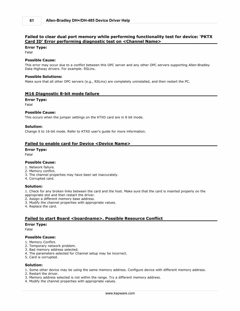
61
www.kepware.com
Allen-Bradley DH+/DH-485 Device Driver Help
Failed to clear dual port memory while performing functionality test for device: 'PKTXCard ID' Error performing diagnostic test on <Channel Name>
Error Type:
Fatal
Possible Cause:
This error may occur due to a conflict between this OPC server and any other OPC servers supporting Allen-BradleyData Highway drivers. For example: RSLinx.
Possible Solutions:
Make sure that all other OPC servers (e.g., RSLinx) are completely uninstalled, and then restart the PC.
M16 Diagnostic 8-bit mode failure
Error Type:
Fatal
Possible Cause:
This occurs when the jumper settings on the KTXD card are in 8 bit mode.
Solution:
Change it to 16-bit mode. Refer to KTXD user's guide for more information.
Failed to enable card for Device <Device Name>
Error Type:
Fatal
Possible Cause:
1. Network failure.2. Memory conflict.3. The channel properties may have been set inaccurately.4. Corrupted card.
Solution:
1. Check for any broken links between the card and the host. Make sure that the card is inserted properly on theappropriate slot and then restart the driver.2. Assign a different memory base address.3. Modify the channel properties with appropriate values.4. Replace the card.
Failed to start Board <boardname>. Possible Resource Conflict
Error Type:
Fatal
Possible Cause:
1. Memory Conflict.2. Temporary network problem.3. Bad memory address selected.4. The parameters selected for Channel setup may be incorrect.5. Card is corrupted.
Solution:
1. Some other device may be using the same memory address. Configure device with different memory address.2. Restart the driver.3. Memory address selected is not within the range. Try a different memory address.4. Modify the channel properties with appropriate values.
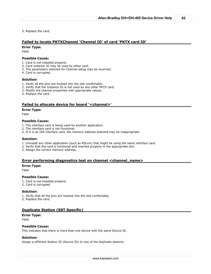
62
www.kepware.com
Allen-Bradley DH+/DH-485 Device Driver Help
5. Replace the card.
Failed to locate PKTXChannel 'Channel ID' of card 'PKTX card ID'
Error Type:
Fatal
Possible Cause:
1. Card is not installed properly.2. Card instance ID may be used by other card.3. The parameters selected for Channel setup may be incorrect.4. Card is corrupted.
Solution:
1. Verify all the pins are hooked into the slot comfortably.2. Verify that the Instance ID is not used by any other PKTX card.3. Modify the channel properties with appropriate values.4. Replace the card.
Failed to allocate device for board '<channel>'
Error Type:
Fatal
Possible Cause:
1. The interface card is being used by another application.2. The interface card is not functional.3. If it is an ISA interface card, the memory address selected may be inappropriate.
Solution:
1. Uninstall any other application (such as RSLinx) that might be using the same interface card.2. Verify that the card is functional and inserted properly in the appropriate slot.3. Assign the correct memory address.
Error performing diagnostics test on channel <channel_name>
Error Type:
Fatal
Possible Cause:
1. Card is not installed properly2. Card is corrupted
Solution:
1. Verify that all the pins are hooked into the slot comfortably.2. Replace the card.
Duplicate Station (SST Specific)
Error Type:
Fatal
Possible Cause:
This indicates that there is more than one device with the same Device ID.
Solution:
Assign a different Station ID (Device ID) to one of the duplicate stations.
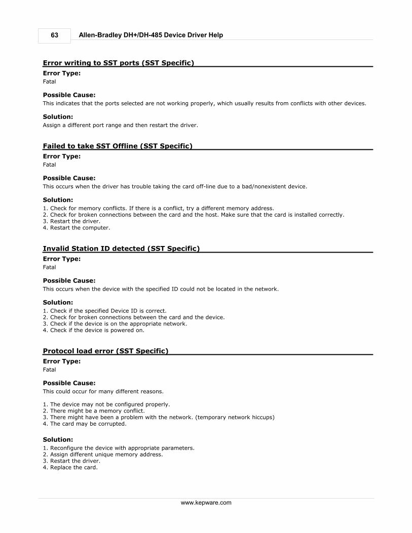
63
www.kepware.com
Allen-Bradley DH+/DH-485 Device Driver Help
Error writing to SST ports (SST Specific)
Error Type:
Fatal
Possible Cause:
This indicates that the ports selected are not working properly, which usually results from conflicts with other devices.
Solution:
Assign a different port range and then restart the driver.
Failed to take SST Offline (SST Specific)
Error Type:
Fatal
Possible Cause:
This occurs when the driver has trouble taking the card off-line due to a bad/nonexistent device.
Solution:
1. Check for memory conflicts. If there is a conflict, try a different memory address.2. Check for broken connections between the card and the host. Make sure that the card is installed correctly.3. Restart the driver.4. Restart the computer.
Invalid Station ID detected (SST Specific)
Error Type:
Fatal
Possible Cause:
This occurs when the device with the specified ID could not be located in the network.
Solution:
1. Check if the specified Device ID is correct.2. Check for broken connections between the card and the device.3. Check if the device is on the appropriate network.4. Check if the device is powered on.
Protocol load error (SST Specific)
Error Type:
Fatal
Possible Cause:
This could occur for many different reasons. 1. The device may not be configured properly.2. There might be a memory conflict.3. There might have been a problem with the network. (temporary network hiccups)4. The card may be corrupted.
Solution:
1. Reconfigure the device with appropriate parameters.2. Assign different unique memory address.3. Restart the driver.4. Replace the card.
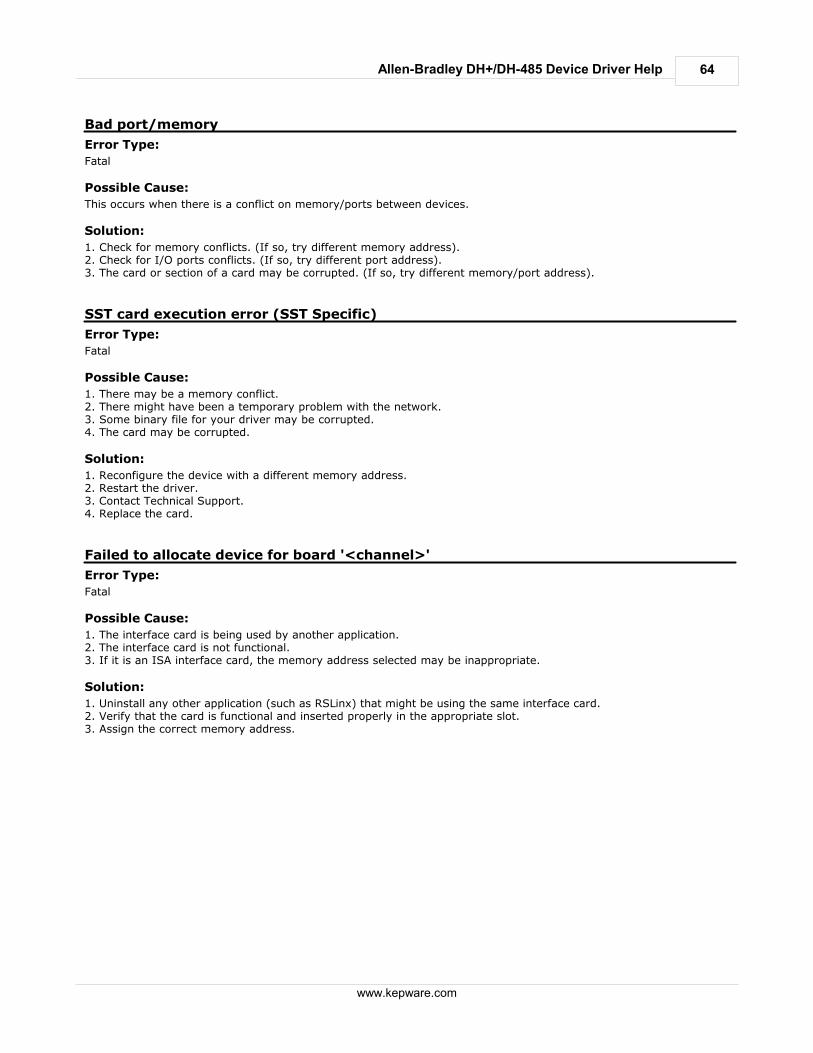
64
www.kepware.com
Allen-Bradley DH+/DH-485 Device Driver Help
Bad port/memory
Error Type:
Fatal
Possible Cause:
This occurs when there is a conflict on memory/ports between devices.
Solution:
1. Check for memory conflicts. (If so, try different memory address).2. Check for I/O ports conflicts. (If so, try different port address).3. The card or section of a card may be corrupted. (If so, try different memory/port address).
SST card execution error (SST Specific)
Error Type:
Fatal
Possible Cause:
1. There may be a memory conflict.2. There might have been a temporary problem with the network.3. Some binary file for your driver may be corrupted.4. The card may be corrupted.
Solution:
1. Reconfigure the device with a different memory address.2. Restart the driver.3. Contact Technical Support.4. Replace the card.
Failed to allocate device for board '<channel>'
Error Type:
Fatal
Possible Cause:
1. The interface card is being used by another application.2. The interface card is not functional.3. If it is an ISA interface card, the memory address selected may be inappropriate.
Solution:
1. Uninstall any other application (such as RSLinx) that might be using the same interface card.2. Verify that the card is functional and inserted properly in the appropriate slot.3. Assign the correct memory address.
Allen-Bradley DH+/DH-485 Device Driver Help65
www.kepware.com
Index- 5 -5136-SD-ISA 4, 17
Hardware Configuration 34
5136-SD-ISA card 17
5136-SD-PCI 4, 19
5136-SD-PCI card 19
- A -AB-specific error descriptions 54
Address Descriptions 43
Allen-Bradley 4, 31
Allen-Bradley DH 4, 31
Array size 56
Array support 57
ASCII file 49
Ascii Files 49
- B -Binary Files 45
Board Type 4, 7
- C -Communication Protocol 31
Communications Parameters 34
Connect timeout 31
Connection/disconnection 59
Control Files 47
Corrupted Card 60, 61
- D -Data Highway Plus 4
Data Highway-485 4
Device 60, 61
Device address 55, 56
Device Manager 37
Device Setup 31
DH-485 4, 7, 31, 39
DH-485 Networks 4, 7, 31, 39
Dual port memory 60
Duplicate Station 62
- E -Enable card 61
Error Descriptions 54
- F -Failed Ram CTC SIO test 59
Failed to allocate device for board '<channel>' 64
Failed to clear dual port memory while performingfunctionality test 61
Failed to connect to device '<device name>' 58
Failed to enable 61
Failed to locate Channel 62
Failed to Start Board 61
File Corruption 57
Float Files 49
- G -General Addressing 43
- H -Hardware Configuration
1784-KTX(D) 35
5136-SD-ISA 34
Hardware Setup 34
- I -Input Files 44
Integer Files 48
Interrupt Configuration 35
Interrupt not configured 57
Invalid Station ID detected 63
IRQ 35, 37
ISA 4, 17, 60

Index 66
www.kepware.com
- L -Load binary resource 60
- M -M16 Diagnosis 59, 60
M16 Diagnostic 8-bit mode failure 61
Memory Configuration 35
Memory Conflict 59, 60, 61, 63, 64
Missing address 55
Modular I/O Selection Guide 40
- O -Optimizing Data Highway Communications 42
Output Files 43
- P -PCMK/B 4, 25
PID Files 51
PLC-5 Family 47, 50, 52, 53
Possible Resource Conflict 61
- S -SLC5/05 Open Addressing 50
SLC500 Slot Configuration 42
Slot Configuration 40, 42
Slot/module list 42
SST Specific 55, 62, 63
Sst specific error descriptions 55
Status Files 46
Supported Devices 31
Syntax error 55
- T -Timeout Parameters 31
Timer Files 46
- U -Unable to write data 57, 58, 59