Allen-Bradley 1734-ACNR - Harvard...
18
5Publication 1734-SG001F-EN-P - September 2015 Chapter 1 POINT I/O Family Overview The POINT I/O family has modular I/O modules that are ideal for applications where flexibility and low-cost of ownership are key for successful control system design and operation. As a key element in the Rockwell Automation Integrated Architecture, its comprehensive diagnostics and configurable features allow the product to be easily applied to any automation system and reduce engineering costs through standardization. It can be used in remote device panels, local control panels, and can be accessed from many locations including the Internet. This product has just-what-you-need granularity in 1 to 8 points to reduce system cost and size. Available features include Channel Level Diagnostics for quick troubleshooting, multiple termination options and flexibility to save money, cabinet space and commissioning/troubleshooting time, the ability to mix/match Safety I/O on the same bus, and available DeviceLogix for local control, fast response time. Self-Configuring modules are also available to reduce/simplify your design and your inventory. Allen-Bradley 1734-ACNR
Transcript of Allen-Bradley 1734-ACNR - Harvard...
5Publication 1734-SG001F-EN-P - September 2015
Chapter 1
POINT I/O Family
Overview
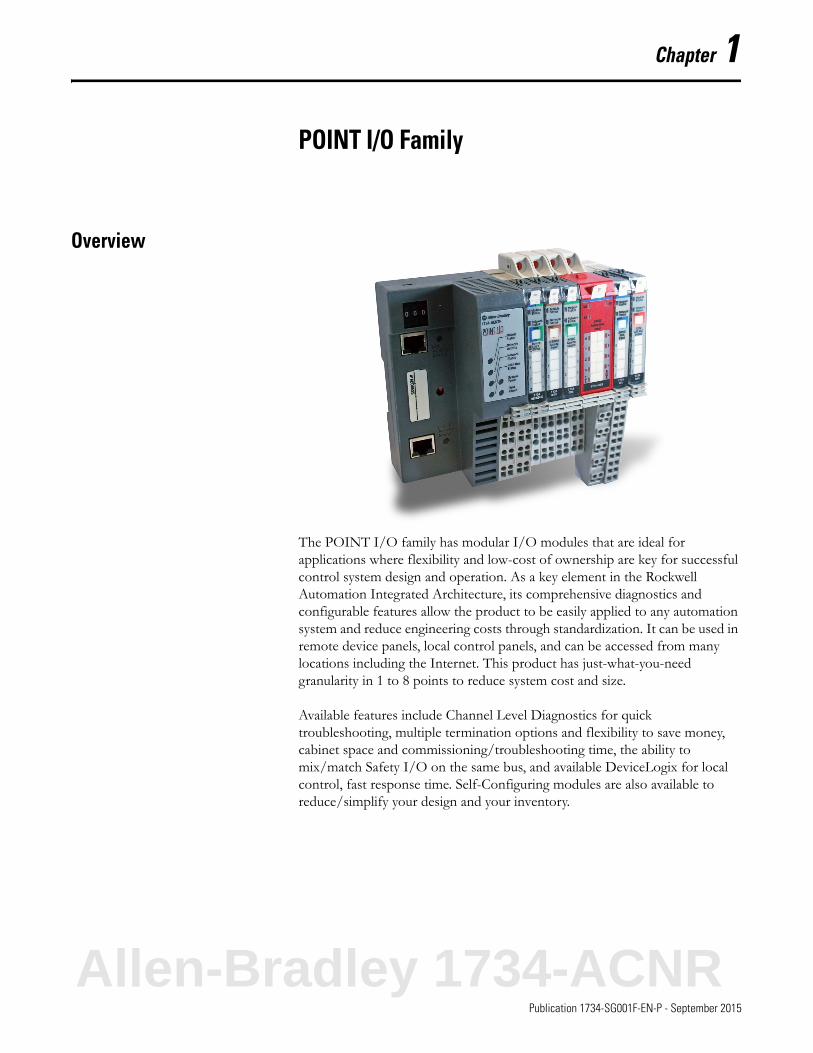
The POINT I/O family has modular I/O modules that are ideal for applications where flexibility and low-cost of ownership are key for successful control system design and operation. As a key element in the Rockwell Automation Integrated Architecture, its comprehensive diagnostics and configurable features allow the product to be easily applied to any automation system and reduce engineering costs through standardization. It can be used in remote device panels, local control panels, and can be accessed from many locations including the Internet. This product has just-what-you-need granularity in 1 to 8 points to reduce system cost and size.
Available features include Channel Level Diagnostics for quick troubleshooting, multiple termination options and flexibility to save money, cabinet space and commissioning/troubleshooting time, the ability to mix/match Safety I/O on the same bus, and available DeviceLogix for local control, fast response time. Self-Configuring modules are also available to reduce/simplify your design and your inventory.
Allen-Bradley 1734-ACNR
Publication 1734-SG001F-EN-P - September 2015
6 POINT I/O Family
The POINT I/O System
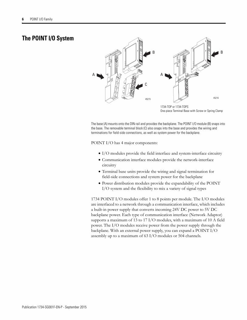
The base (A) mounts onto the DIN rail and provides the backplane. The POINT I/O module (B) snaps into the base. The removable terminal block (C) also snaps into the base and provides the wiring and terminations for field-side connections, as well as system power for the backplane.
POINT I/O has 4 major components:
• I/O modules provide the field interface and system-interface circuitry
• Communication interface modules provide the network-interface circuitry
• Terminal base units provide the wiring and signal termination for field-side connections and system power for the backplane
• Power distribution modules provide the expandability of the POINT I/O system and the flexibility to mix a variety of signal types
1734 POINT I/O modules offer 1 to 8 points per module. The I/O modules are interfaced to a network through a communication interface, which includes a built-in power supply that converts incoming 24V DC power to 5V DC backplane power. Each type of communication interface (Network Adaptor) supports a maximum of 13 to 17 I/O modules, with a maximum of 10 A field power. The I/O modules receive power from the power supply through the backplane. With an external power supply, you can expand a POINT I/O assembly up to a maximum of 63 I/O modules or 504 channels.
A
B
C
A
B
45215 45216
1734-TOP or 1734-TOPSOne-piece Terminal Base with Screw or Spring Clamp
Publication 1734-SG001F-EN-P - September 2015
POINT I/O Family 7
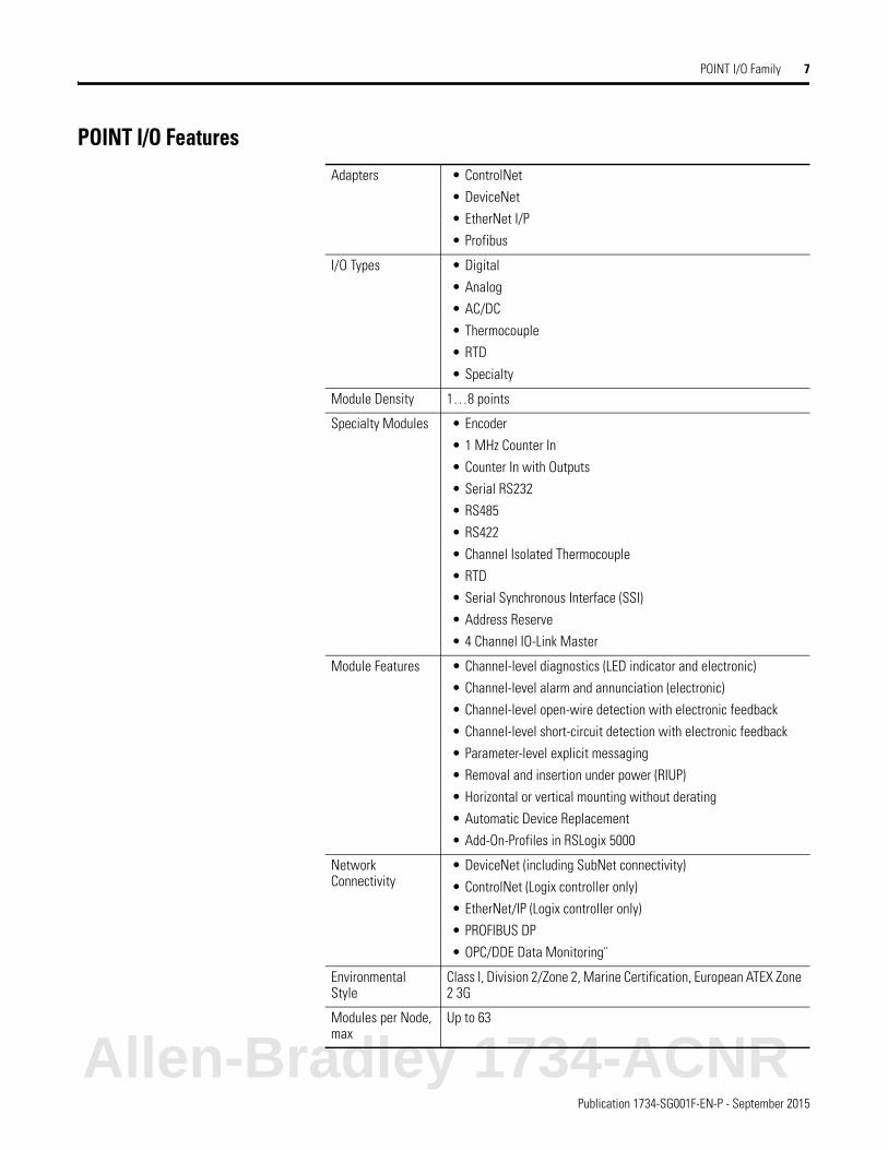
POINT I/O FeaturesAdapters • ControlNet
• DeviceNet
• EtherNet I/P
• Profibus
I/O Types • Digital
• Analog
• AC/DC
• Thermocouple
• RTD
• Specialty
Module Density 1…8 points
Specialty Modules • Encoder
• 1 MHz Counter In
• Counter In with Outputs
• Serial RS232
• RS485
• RS422
• Channel Isolated Thermocouple
• RTD
• Serial Synchronous Interface (SSI)
• Address Reserve
• 4 Channel IO-Link Master
Module Features • Channel-level diagnostics (LED indicator and electronic)
• Channel-level alarm and annunciation (electronic)
• Channel-level open-wire detection with electronic feedback
• Channel-level short-circuit detection with electronic feedback
• Parameter-level explicit messaging
• Removal and insertion under power (RIUP)
• Horizontal or vertical mounting without derating
• Automatic Device Replacement
• Add-On-Profiles in RSLogix 5000
Network Connectivity
• DeviceNet (including SubNet connectivity)
• ControlNet (Logix controller only)
• EtherNet/IP (Logix controller only)
• PROFIBUS DP
• OPC/DDE Data Monitoring¨
Environmental Style
Class I, Division 2/Zone 2, Marine Certification, European ATEX Zone 2 3G
Modules per Node, max
Up to 63
Allen-Bradley 1734-ACNR
Publication 1734-SG001F-EN-P - September 2015
8 POINT I/O Family
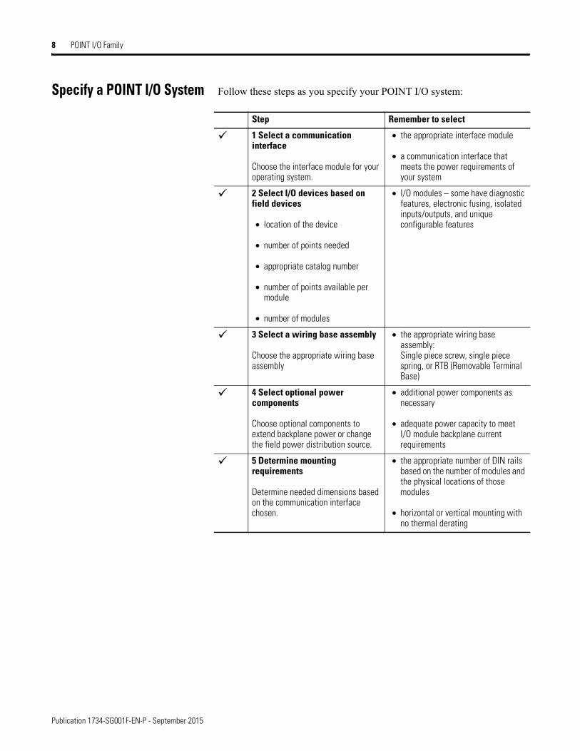
Specify a POINT I/O System Follow these steps as you specify your POINT I/O system:
Step Remember to select
1 Select a communication interface
Choose the interface module for your operating system.
• the appropriate interface module
• a communication interface that meets the power requirements of your system
2 Select I/O devices based on field devices
• location of the device
• number of points needed
• appropriate catalog number
• number of points available per module
• number of modules
• I/O modules – some have diagnostic features, electronic fusing, isolated inputs/outputs, and unique configurable features
3 Select a wiring base assembly
Choose the appropriate wiring base assembly
• the appropriate wiring base assembly:Single piece screw, single piece spring, or RTB (Removable Terminal Base)
4 Select optional power components
Choose optional components to extend backplane power or change the field power distribution source.
• additional power components as necessary
• adequate power capacity to meet I/O module backplane current requirements
5 Determine mounting requirements
Determine needed dimensions based on the communication interface chosen.
• the appropriate number of DIN rails based on the number of modules and the physical locations of those modules
• horizontal or vertical mounting with no thermal derating
9Publication 1734-SG001F-EN-P - September 2015
Chapter 2
Select POINT I/O Communication Interfaces
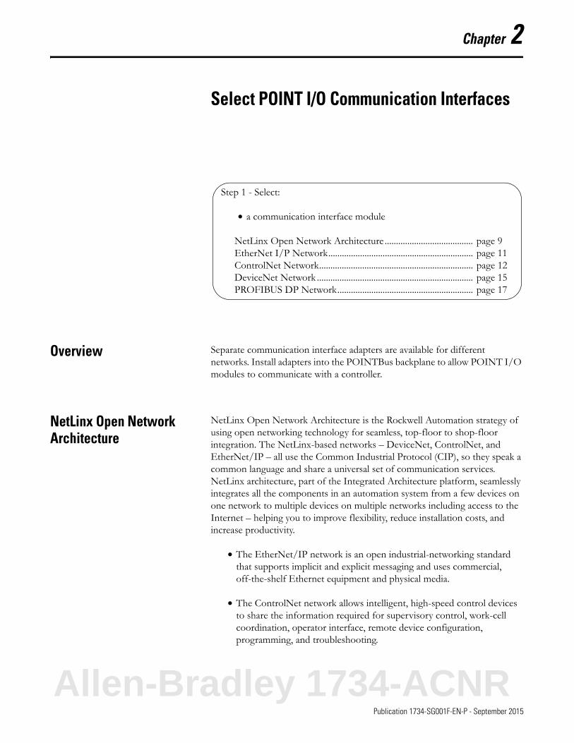
Overview Separate communication interface adapters are available for different networks. Install adapters into the POINTBus backplane to allow POINT I/O modules to communicate with a controller.
NetLinx Open Network Architecture
NetLinx Open Network Architecture is the Rockwell Automation strategy of using open networking technology for seamless, top-floor to shop-floor integration. The NetLinx-based networks – DeviceNet, ControlNet, and EtherNet/IP – all use the Common Industrial Protocol (CIP), so they speak a common language and share a universal set of communication services. NetLinx architecture, part of the Integrated Architecture platform, seamlessly integrates all the components in an automation system from a few devices on one network to multiple devices on multiple networks including access to the Internet – helping you to improve flexibility, reduce installation costs, and increase productivity.
• The EtherNet/IP network is an open industrial-networking standard that supports implicit and explicit messaging and uses commercial, off-the-shelf Ethernet equipment and physical media.
• The ControlNet network allows intelligent, high-speed control devices to share the information required for supervisory control, work-cell coordination, operator interface, remote device configuration, programming, and troubleshooting.
Step 1 - Select:
• a communication interface module
NetLinx Open Network Architecture ....................................... page 9EtherNet I/P Network................................................................ page 11ControlNet Network.................................................................... page 12DeviceNet Network ..................................................................... page 15PROFIBUS DP Network............................................................ page 17
Allen-Bradley 1734-ACNR
Publication 1734-SG001F-EN-P - September 2015
10 Select POINT I/O Communication Interfaces
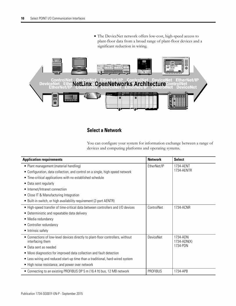
• The DeviceNet network offers low-cost, high-speed access to plant-floor data from a broad range of plant-floor devices and a significant reduction in wiring.
Select a Network
You can configure your system for information exchange between a range of devices and computing platforms and operating systems.
Application requirements Network Select
• Plant management (material handling)
• Configuration, data collection, and control on a single, high-speed network
• Time-critical applications with no established schedule
• Data sent regularly
• Internet/Intranet connection
• Close IT & Manufacturing Integration
• Built-in switch, or high availability requirement (2-port AENTR)
EtherNet/IP 1734-AENT1734-AENTR
• High-speed transfer of time-critical data between controllers and I/O devices
• Deterministic and repeatable data delivery
• Media redundancy
• Controller redundancy
• Intrinsic safety
ControlNet 1734-ACNR
• Connections of low-level devices directly to plant-floor controllers, without interfacing them
• Data sent as needed
• More diagnostics for improved data collection and fault detection
• Less wiring and reduced start-up time than a traditional, hard-wired system
• High noise resistance, and power over network
DeviceNet 1734-ADN1734-ADN(X)1734-PDN
• Connecting to an existing PROFIBUS DP 5 m (16.4 ft) bus, 12 MB network PROFIBUS 1734-APB
Publication 1734-SG001F-EN-P - September 2015
12 Select POINT I/O Communication Interfaces
ControlNet Network The ControlNet network is an open, state-of-the-art control network that meets the demands of real-time, high-throughput applications. The ControlNet network uses the proven Common Industrial Protocol (CIP) to combine the functionality of an I/O network and a peer-to-peer network providing high-speed performance for both functions. The ControlNet
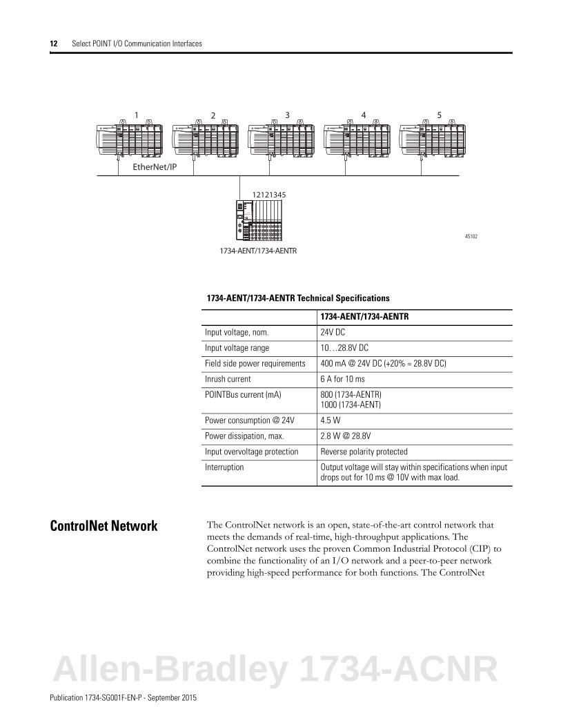
1 2 3 4 5
EtherNet/IP
12121345
1734-AENT/1734-AENTR
45102
1734-AENT/1734-AENTR Technical Specifications
1734-AENT/1734-AENTR
Input voltage, nom. 24V DC
Input voltage range 10…28.8V DC
Field side power requirements 400 mA @ 24V DC (+20% = 28.8V DC)
Inrush current 6 A for 10 ms
POINTBus current (mA) 800 (1734-AENTR)1000 (1734-AENT)
Power consumption @ 24V 4.5 W
Power dissipation, max. 2.8 W @ 28.8V
Input overvoltage protection Reverse polarity protected
Interruption Output voltage will stay within specifications when input drops out for 10 ms @ 10V with max load.
Allen-Bradley 1734-ACNR
Publication 1734-SG001F-EN-P - September 2015
Select POINT I/O Communication Interfaces 13
network gives you deterministic, repeatable transfers of all mission-critical control data in addition to supporting transfers of non-time-critical data.
The 1734-ACNR ControlNet adapter provides high-speed transfer of time critical data between controllers and I/O devices. It manages data transfers between controllers on the ControlNet network and POINT I/O modules plugged into the POINTBus backplane. The ControlNet network allows the exchange of messages between ControlNet products compliant with the ControlNet International specification. The 1734-ACNR adapter features include a variety of control system solutions, local communication network access through the network access port (NAP), and redundant media. It requires Series C POINT I/O modules or later.
The 1734-ACNR adapter requires a typical 24V DC power supply with a maximum of 10.2 W of power. It provides a maximum backplane current of 1.0 A at 5V DC. Backplane current can be extended beyond 1.0 A with a 1734-EP24DC backplane extension power supply. The 1734-EP24DC can supply up to an additional 1.3 A of backplane current. Multiple 1734-EP24DC power supplies can be used to reach the maximum limit of 63 POINT I/O modules if 25 or fewer of these modules are analog or specialty modules.
The adapter supports 25 direct and 5 rack I/O connections to the POINT I/O modules. From a single 1734-ACNR adapter, multiple controllers establish I/O connections, up to a maximum of 5 rack I/O connections per adapter. Direct connections must be used with analog and specialty modules. Multiple rack connections permit multiple controllers to connect to I/O over a single 1734-ACNR adapter. The number of connections that can be supported on a network depends on the ControlNet parameters (NUT, RPI, and API) and the POINT I/O configuration by itself (number and types of I/O modules).
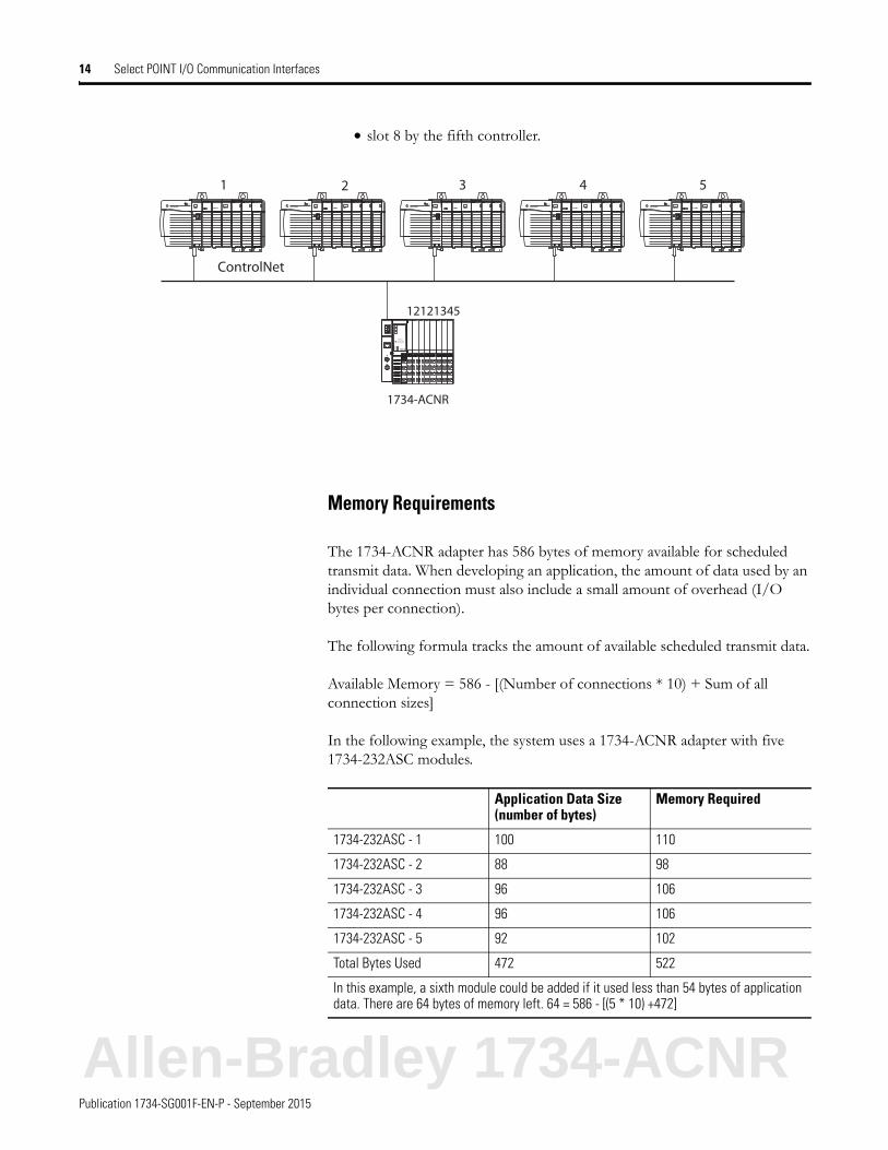
The following example shows a single POINT I/O ControlNet adapter with 5 connections and 8 I/O modules. The POINT I/O modules are monitored by the 5 controllers on the ControlNet network. The POINT I/O modules in:
• slots 1, 3, and 5 are controlled by the first controller.
• slots 2 and 4 by the second controller.
• slot 6 by the third controller.
• slot 7 by the fourth controller.
ControlNet Network Considerations
Adapter Considerations
1734-ACNR A total of 63 POINT I/O modules can be assembled on a single ControlNet node.
Expansion power supplies may be used to provide additional POINTBus backplane current.
Up to 25 direct connections and 5 rack connections are allowed.
Publication 1734-SG001F-EN-P - September 2015
14 Select POINT I/O Communication Interfaces
• slot 8 by the fifth controller.
Memory Requirements
The 1734-ACNR adapter has 586 bytes of memory available for scheduled transmit data. When developing an application, the amount of data used by an individual connection must also include a small amount of overhead (I/O bytes per connection).
The following formula tracks the amount of available scheduled transmit data.
Available Memory = 586 - [(Number of connections * 10) + Sum of all connection sizes]
In the following example, the system uses a 1734-ACNR adapter with five 1734-232ASC modules.
1 2 3 4 5
ControlNet
12121345
1734-ACNR
Application Data Size (number of bytes)
Memory Required
1734-232ASC - 1 100 110
1734-232ASC - 2 88 98
1734-232ASC - 3 96 106
1734-232ASC - 4 96 106
1734-232ASC - 5 92 102
Total Bytes Used 472 522
In this example, a sixth module could be added if it used less than 54 bytes of application data. There are 64 bytes of memory left. 64 = 586 - [(5 * 10) +472]
Allen-Bradley 1734-ACNR
Publication 1734-SG001F-EN-P - September 2015
Select POINT I/O Communication Interfaces 15
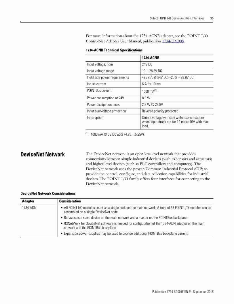
For more information about the 1734-ACNR adapter, see the POINT I/O ControlNet Adapter User Manual, publication 1734-UM008.
DeviceNet Network The DeviceNet network is an open low-level network that provides connections between simple industrial devices (such as sensors and actuators) and higher-level devices (such as PLC controllers and computers). The DeviceNet network uses the proven Common Industrial Protocol (CIP) to provide the control, configure, and data collection capabilities for industrial devices. The POINT I/O family offers four interfaces for connecting to the DeviceNet network.
1734-ACNR Technical Specifications
1734-ACNR
Input voltage, nom 24V DC
Input voltage range 10…28.8V DC
Field side power requirements 425 mA @ 24V DC (+20% = 28.8V DC)
Inrush current 6 A for 10 ms
POINTBus current 1000 mA(1)
(1) 1000 mA @ 5V DC ±5% (4.75…5.25V).
Power consumption at 24V 8.0 W
Power dissipation, max. 2.8 W @ 28.8V
Input overvoltage protection Reverse polarity protected
Interruption Output voltage will stay within specifications when input drops out for 10 ms at 10V with max load.
DeviceNet Network Considerations
Adapter Consideration
1734-ADN • All POINT I/O modules count as a single node on the main network. A total of 63 POINT I/O modules can be assembled on a single DeviceNet node.
• Behaves as a slave device on the main network and a master on the POINTBus backplane.
• RSNetWorx for DeviceNet software is needed for configuration of the 1734-ADN adapter on the main network and the POINTBus backplane
• Expansion power supplies may be used to provide additional POINTBus backplane current.
63Publication 1734-SG001F-EN-P - September 2015
Chapter 6
Mounting Requirements
The producer/consumer model multicasts messages. This means that multiple nodes can consume the same data at the same time from a single device. Where you place POINT I/O modules in the control system determines how the modules exchange data.
For a Rockwell Automation controller to control 1734 I/O, the I/O must be on one of the following:
• the same network as the controller.
• a ControlNet network that is local to that controller.
• an EtherNet/IP network that is local to that controller.
Power Supply Distance Rating
Place modules to the right of the power supply. Each 1734 I/O module can be placed in any of the slots right of the power supply until the usable backplane current of that supply has been exhausted. An adapter provides 1000 mA current to the POINTBus backplane. The 1734-EP24DC or 1734-EPAC Expansion power supply provides up to 1300 mA. I/O modules require from 75 mA (typical for the digital and analog I/O modules) up to 220 mA or more.
Step 5 - Select:
• appropriate number of DIN rails based on the number of modules and the physical requirements
Power Supply Distance Rating ................................................... page 63Mount the POINT I/O System................................................. page 64
Allen-Bradley 1734-ACNR
Publication 1734-SG001F-EN-P - September 2015
64 Mounting Requirements
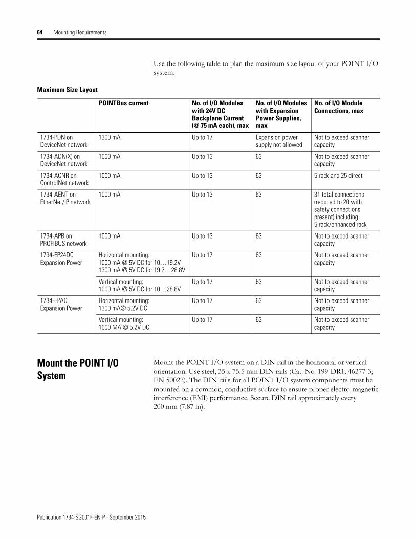
Use the following table to plan the maximum size layout of your POINT I/O system.
Mount the POINT I/O System
Mount the POINT I/O system on a DIN rail in the horizontal or vertical orientation. Use steel, 35 x 75.5 mm DIN rails (Cat. No. 199-DR1; 46277-3; EN 50022). The DIN rails for all POINT I/O system components must be mounted on a common, conductive surface to ensure proper electro-magnetic interference (EMI) performance. Secure DIN rail approximately every 200 mm (7.87 in).
Maximum Size Layout
POINTBus current No. of I/O Modules with 24V DC Backplane Current (@ 75 mA each), max
No. of I/O Modules with Expansion Power Supplies, max
No. of I/O Module Connections, max
1734-PDN on DeviceNet network
1300 mA Up to 17 Expansion power supply not allowed
Not to exceed scanner capacity
1734-ADN(X) on DeviceNet network
1000 mA Up to 13 63 Not to exceed scanner capacity
1734-ACNR on ControlNet network
1000 mA Up to 13 63 5 rack and 25 direct
1734-AENT on EtherNet/IP network
1000 mA Up to 13 63 31 total connections (reduced to 20 with safety connections present) including 5 rack/enhanced rack
1734-APB on PROFIBUS network
1000 mA Up to 13 63 Not to exceed scanner capacity
1734-EP24DC Expansion Power
Horizontal mounting: 1000 mA @ 5V DC for 10…19.2V1300 mA @ 5V DC for 19.2…28.8V
Up to 17 63 Not to exceed scanner capacity
Vertical mounting: 1000 mA @ 5V DC for 10…28.8V
Up to 17 63 Not to exceed scanner capacity
1734-EPAC Expansion Power
Horizontal mounting: 1300 mA@ 5.2V DC
Up to 17 63 Not to exceed scanner capacity
Vertical mounting: 1000 MA @ 5.2V DC
Up to 17 63 Not to exceed scanner capacity
Publication 1734-SG001F-EN-P - September 2015
Mounting Requirements 65
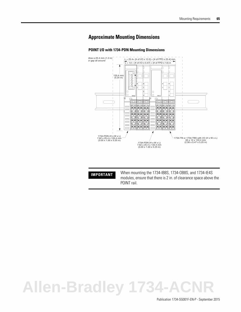
Approximate Mounting Dimensions
POINT I/O with 1734-PDN Mounting Dimensions
IMPORTANT When mounting the 1734-IB8S, 1734-OB8S, and 1734-IE4S modules, ensure that there is 2 in. of clearance space above the POINT rail.
Allow a 25.4 mm (1.0 in)air gap all around
133.4 mm (5.25 in)
1734-PDN (H x W x L)7.62 x 25.4 x 133.4 mm(3.00 x 1.00 x 5.25 in)
1734-FDN (H x W x L)7.62 x 25.4 x 133.4 mm(3.00 x 1.00 x 5.25 in)
1734-TB or 1734-TBS with I/O (H x W x L)65 x 12 x 133.4 mm
(2.56 x 0.47 x 5.25 in)
Allen-Bradley 1734-ACNR
Publication 1734-SG001F-EN-P - September 2015
66 Mounting Requirements
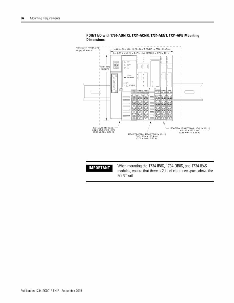
POINT I/O with 1734-ADN(X), 1734-ACNR, 1734-AENT, 1734-APB Mounting Dimensions
133.4 mm (5.25 in)
1734-ADN (H x W x L)7.62 x 54.9 x 133.4 mm(3.00 x 2.16 x 5.25 in)
Allow a 25.4 mm (1.0 in)air gap all around
1734-EP24DC or 1734-FPD (H x W x L)7.62 x 25.4 x 133.4 mm(3.00 x 1.00 x 5.25 in)
1734-TB or 1734-TBS with I/O (H x W x L)65 x 12 x 133.4 mm
(2.56 x 0.47 x 5.25 in)
IMPORTANT When mounting the 1734-IB8S, 1734-OB8S, and 1734-IE4S modules, ensure that there is 2 in. of clearance space above the POINT rail.
Publication 1734-SG001F-EN-P - September 2015
Related Documentation 69
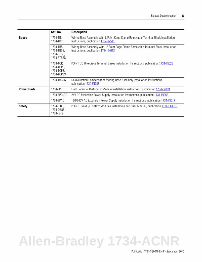
Bases 1734-TB, 1734-TBS
Wiring Base Assembly with 8 Point Cage-Clamp Removable Terminal Block Installation Instructions, publication 1734-IN511
1734-TBS, 1734-TB3S, 1734-RTBS, 1734-RTB3S
Wiring Base Assembly with 12 Point Cage-Clamp Removable Terminal Block Installation Instructions, publication 1734-IN013
1734-TOP, 1734-TOPS, 1734-TOP3, 1734-TOP3S
POINT I/O One-piece Terminal Bases Installation Instructions, publication 1734-IN028
1734-TBCJC Cold Junction Compensation Wiring Base Assembly Installation Instructions, publication 1734-IN583
Power Units 1734-FPD Field Potential Distributor Module Installation Instructions, publication 1734-IN059
1734-EP24DC 24V DC Expansion Power Supply Installation Instructions, publication 1734-IN058
1734-EPAC 120/240V AC Expansion Power Supply Installation Instructions, publication 1734-IN017
Safety 1734-IB8S, 1734-OB8S, 1734-IE4S
POINT Guard I/O Safety Modules Installation and User Manual, publication 1734-UM013
Cat. No. Description
Allen-Bradley 1734-ACNR
55Publication 1734-SG001F-EN-P - September 2015
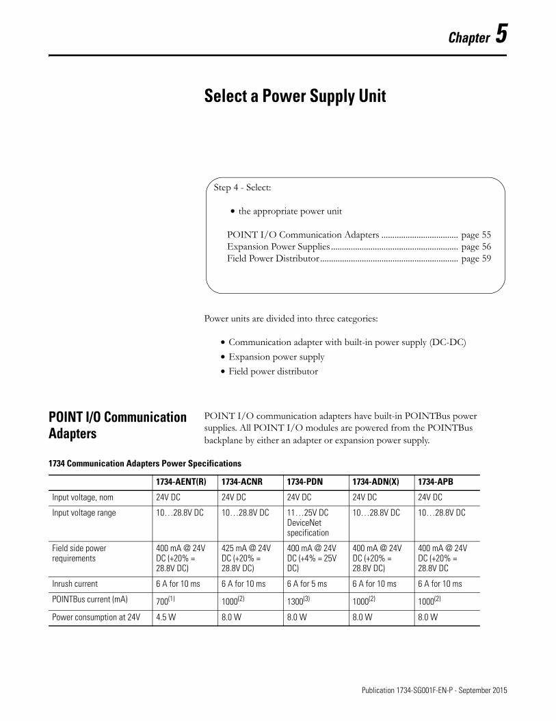
Chapter 5
Select a Power Supply Unit
Power units are divided into three categories:
• Communication adapter with built-in power supply (DC-DC)
• Expansion power supply
• Field power distributor
POINT I/O Communication Adapters
POINT I/O communication adapters have built-in POINTBus power supplies. All POINT I/O modules are powered from the POINTBus backplane by either an adapter or expansion power supply.
Step 4 - Select:
• the appropriate power unit
POINT I/O Communication Adapters ................................... page 55Expansion Power Supplies .......................................................... page 56Field Power Distributor ............................................................... page 59
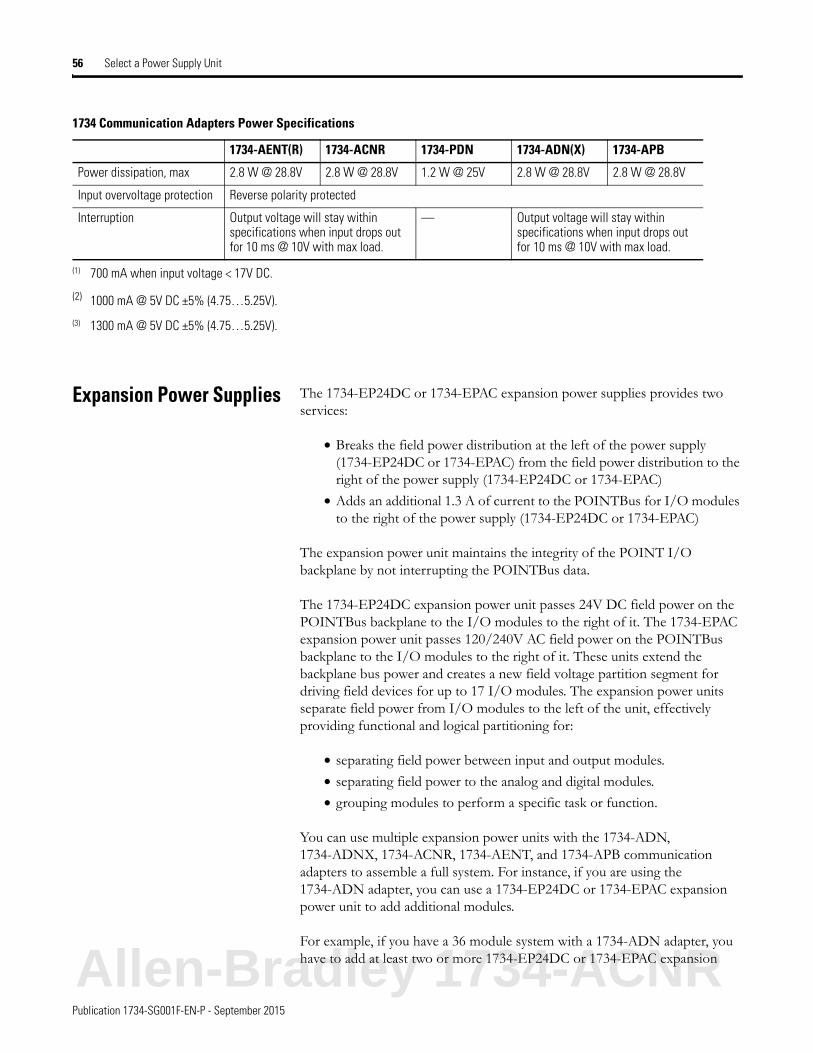
1734 Communication Adapters Power Specifications
1734-AENT(R) 1734-ACNR 1734-PDN 1734-ADN(X) 1734-APB
Input voltage, nom 24V DC 24V DC 24V DC 24V DC 24V DC
Input voltage range 10…28.8V DC 10…28.8V DC 11…25V DC DeviceNet specification
10…28.8V DC 10…28.8V DC
Field side power requirements
400 mA @ 24V DC (+20% = 28.8V DC)
425 mA @ 24V DC (+20% = 28.8V DC)
400 mA @ 24V DC (+4% = 25V DC)
400 mA @ 24V DC (+20% = 28.8V DC)
400 mA @ 24V DC (+20% = 28.8V DC
Inrush current 6 A for 10 ms 6 A for 10 ms 6 A for 5 ms 6 A for 10 ms 6 A for 10 ms
POINTBus current (mA) 700(1) 1000(2) 1300(3) 1000(2) 1000(2)
Power consumption at 24V 4.5 W 8.0 W 8.0 W 8.0 W 8.0 W
Publication 1734-SG001F-EN-P - September 2015
56 Select a Power Supply Unit
Expansion Power Supplies The 1734-EP24DC or 1734-EPAC expansion power supplies provides two services:
• Breaks the field power distribution at the left of the power supply (1734-EP24DC or 1734-EPAC) from the field power distribution to the right of the power supply (1734-EP24DC or 1734-EPAC)
• Adds an additional 1.3 A of current to the POINTBus for I/O modules to the right of the power supply (1734-EP24DC or 1734-EPAC)
The expansion power unit maintains the integrity of the POINT I/O backplane by not interrupting the POINTBus data.
The 1734-EP24DC expansion power unit passes 24V DC field power on the POINTBus backplane to the I/O modules to the right of it. The 1734-EPAC expansion power unit passes 120/240V AC field power on the POINTBus backplane to the I/O modules to the right of it. These units extend the backplane bus power and creates a new field voltage partition segment for driving field devices for up to 17 I/O modules. The expansion power units separate field power from I/O modules to the left of the unit, effectively providing functional and logical partitioning for:
• separating field power between input and output modules.
• separating field power to the analog and digital modules.
• grouping modules to perform a specific task or function.
You can use multiple expansion power units with the 1734-ADN, 1734-ADNX, 1734-ACNR, 1734-AENT, and 1734-APB communication adapters to assemble a full system. For instance, if you are using the 1734-ADN adapter, you can use a 1734-EP24DC or 1734-EPAC expansion power unit to add additional modules.
For example, if you have a 36 module system with a 1734-ADN adapter, you have to add at least two or more 1734-EP24DC or 1734-EPAC expansion
Power dissipation, max 2.8 W @ 28.8V 2.8 W @ 28.8V 1.2 W @ 25V 2.8 W @ 28.8V 2.8 W @ 28.8V
Input overvoltage protection Reverse polarity protected
Interruption Output voltage will stay within specifications when input drops out for 10 ms @ 10V with max load.
— Output voltage will stay within specifications when input drops out for 10 ms @ 10V with max load.
(1) 700 mA when input voltage < 17V DC.
(2) 1000 mA @ 5V DC ±5% (4.75…5.25V).
(3) 1300 mA @ 5V DC ±5% (4.75…5.25V).
1734 Communication Adapters Power Specifications
1734-AENT(R) 1734-ACNR 1734-PDN 1734-ADN(X) 1734-APB
Allen-Bradley 1734-ACNR
Publication 1734-SG001F-EN-P - September 2015
Select a Power Supply Unit 57
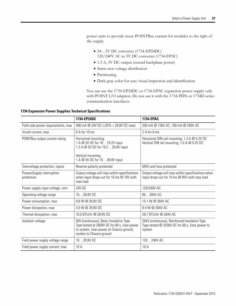
power units to provide more POINTBus current for modules to the right of the supply.
• 24…5V DC converter (1734-EP24DC)120/240V AC to 5V DC converter (1734-EPAC)
• 1.3 A, 5V DC output (extend backplane power)
• Starts new voltage distribution
• Partitioning
• Dark-gray color for easy visual inspection and identification
You can use the 1734-EP24DC or 1734-EPAC expansion power supply only with POINT I/O adapters. Do not use it with the 1734-PDN or 1734D series communication interfaces.
1734 Expansion Power Supplies Technical Specifications
1734-EP24DC 1734-EPAC
Field side power requirements, max 400 mA @ 24V DC (+20% = 28.8V DC max) 200 mA @ 120V AC, 100 mA @ 240V AC
Inrush current, max 6 A for 10 ms 2 A for 6 ms
POINTBus output current rating Horizontal mounting:1 A @ 5V DC for 10…19.2V input1.3 A @ 5V DC for 19.2…28.8V input
Vertical mounting: 1 A @ 5V DC for 10…28.8V input
Horizontal DIN rail mounting: 1.3 A @ 5.2V DCVertical DIN rail mounting: 1.0 A @ 5.2V DC
Overvoltage protection, inputs Reverse polarity protected MOV and fuse protected
PowersSupply interruption protection
Output voltage will stay within specifications when input drops out for 10 ms @ 10V with max load
Output voltage will stay within specifications when input drops out for 10 ms @ 85V with max load
Power supply input voltage, nom 24V DC 120/240V AC
Operating voltage range 10…28.8V DC 85…264V AC
Power consumption, max 9.8 W @ 28.8V DC 15.1 W @ 264V AC
Power dissipation, max 3.0 W @ 28.8V DC 8.4 W @ 264V AC
Thermal dissipation, max 10.0 BTU/hr @ 28.8V DC 28.7 BTU/hr @ 264V AC
Isolation voltage 50V (continuous), Basic Insulation TypeType tested at 2600V DC for 60 s, User power to system, User power to Chassis ground, system to Chassis ground
264V (continuous), Reinforced Insulation TypeType tested @ 3250V DC for 60 s, User power to system
Field power supply voltage range 10…28.8V DC 120…240V AC
Field power supply current, max 10 A 10 A