Allan Block · Before Kalyan-Bhiwandi Naka, Opp Tata Amantra, Pimplas, Thane, Maharashtra 421302...
64
allanblock.in allanblock.in PraYoSa Buildmat Pvt. Ltd. Blg No F4- Gala No 6, Bhumi World - Industrial Park, Pimplas Village, Mumbai-Nashik Highway, Before Kalyan-Bhiwandi Naka, Opp Tata Amantra, Pimplas, Thane, Maharashtra 421302 Tel: +91 7045592934 Email: [email protected] Represented in India by PraYoSa - Offering World Class Products to Beautify Indian Landscapes AB Fieldstone Collection Installation Manual Allan Block Retaining Walls ® ®
Transcript of Allan Block · Before Kalyan-Bhiwandi Naka, Opp Tata Amantra, Pimplas, Thane, Maharashtra 421302...

allanblock.in
allanblock.in
PraYoSa Buildmat Pvt. Ltd.Blg No F4- Gala No 6, Bhumi World - Industrial Park,
Pimplas Village, Mumbai-Nashik Highway,Before Kalyan-Bhiwandi Naka, Opp Tata Amantra, Pimplas,
Thane, Maharashtra 421302 Tel: +91 7045592934
Email: [email protected]
Represented in India by PraYoSa - Offering World Class Products to Beautify Indian Landscapes
AB Fieldstone CollectionInstallation Manual
Allan Block Retaining Walls®
®

About Us
Allan Block is a leading provider of patented retaining wall systems for large-scale commercial, industrial, roadway and residential projects.
For over twenty years, Allan Block has been helping landscape and construction professionals build better walls. With hundreds of millions ofsquare feet of Allan Block in theground, we can deliver the quality and performance you need. Our widerange of products allows you to be creative, efficient, and confident onevery job.
Thank you for using Allan Block.
allanblock.in
Table of Contents
allanblock.in
Allan Block System 5AB Fieldstone Product 6AB System 7Gravity Walls 8Reinforced Walls 10Other Reinforcement Options 12
Plan / Design 13Develop a Plan 14Design Evaluation 17
Build with AB Fieldstone Collection 19Gravity Wall Construction 22Reinforced Wall Construction 24Working with Geogrid 26No-Fines Concrete Backfill & Installation 27Working with Soils 29Compaction 30Water Management 31
Construction Details 33Curves 34Curves with Geogrid 35Corners 36Corners with Geogrid 37Finishing Walls 38Stairs 40Parapets 42Terraces 44Design Details 46Construction and Inspection Checklist 48Material Estimate Worksheet 50Geogrid and No-Fines Estimating Charts 52
Specifications 54References 59
Charts and TablesProducts 6Standard Product Specifications 7Maximum Wall Heights 8Soils 14Setback 16Friction Angle and Soil Weight 29Minimum Radius 35Geogrid and No-Fines Concrete 52
1

Why Choose to use AB Fieldstone
• Has the look and feel of natural stone
• Easier to install than natural stone
• Fraction of the cost of natural stone
• The two-piece system is lighter inweight than natural stone
• Build taller walls without geogrid
• Built-in corner blocks
• Facing units can be rotated for additional looks and styles
• Retaining walls and parapet walls allwith one product line
• Every block is the exact same height
• Environmentally friendly productLong anchoring unit(LAU)
Parapet
RetainingWall
Short anchoring units(SAU)
allanblock.in
2 allanblock.in

812 facing units* with SAU & LAU 824 facing unit with SAU & LAU
AB Fieldstone is a two-piece system with interchangeable facing units and anchoring units. The facing units come in 2 sizes -812 and 824. They can be used individually or mixed together in the project. There is no top or bottom for the facing units, soflipping them over, adds an even more random style, creating a natural stone look.
The anchoring units also come in 2 sizes, compatible with both facing unit sizes and are made out of recycled materials.The short anchoring units (SAU) make a block that is 12 in. (300 mm) deep and the long anchoring units (LAU) make a blockthat is 24 in. (600 mm) deep making them ideal for taller walls with no added reinforcement.
* One in every four 812 facing units is a corner unit.
allanblock.in 3
4 allanblock.in
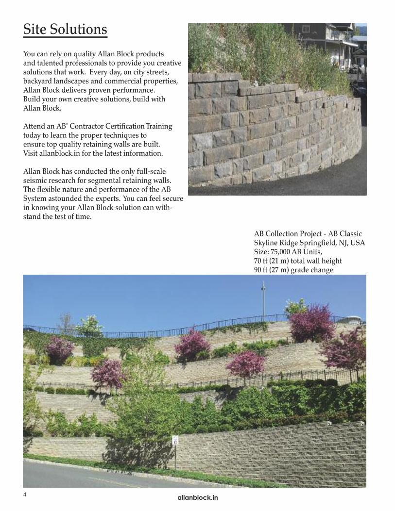
Site Solutions
You can rely on quality Allan Block products and talented professionals to provide you creative solutions that work. Every day, on city streets, backyard landscapes and commercial properties, Allan Block delivers proven performance. Build your own creative solutions, build with Allan Block.
Attend an AB® Contractor Certification Training today to learn the proper techniques to ensure top quality retaining walls are built. Visit allanblock.in for the latest information.
Allan Block has conducted the only full-scale seismic research for segmental retaining walls.The flexible nature and performance of the ABSystem astounded the experts. You can feel securein knowing your Allan Block solution can with-stand the test of time.
AB Collection Project - AB ClassicSkyline Ridge Springfield, NJ, USASize: 75,000 AB Units, 70 ft (21 m) total wall height 90 ft (27 m) grade change

5
Allan Block product and wall system information.
allanblock.in
AB Fieldstone Product 6AB System 7Gravity Walls 8Reinforced Walls 10Other Reinforcement Options 12
SYSTEM
ALLAN BLOCK SYSTEM
allanblock.in

allanblock.in6
AB Fieldstone® Collection
The AB Fieldstone® Collection is a“Green/Eco-Friendly” retaining wall product that maintains the beautiful lookand feel of natural stone. Installing andperforming like our other Collections, AB Fieldstone truly is a friendly product.
AB Fieldstone Collection - Green, Natural, Friendly®
The AB Fieldstone Collection offers a variety of sizes and weights to meet differing aesthetic and performance needs. Use the basic gravity wall system for smaller wall projects. For taller wall projects use geogrid to reinforce the wall, or con-sider optional techniques using masonry, no-fines, rock bolts, soil nails, or earth anchors. AB Fieldstone can offer a choiceof styles to meet your site and design requirements. Refer to the chart below or to our website - allanblock.in to help makethe right choice for your project.
Table 1.1
Actual dimensions, weights and setbacks will vary by manufacturer. Check with your local Allan Block manufacturer for exactspecifications and color availability. Caps and corner blocks are also available for each of the collections.
Green, Natural & Friendly Name Setback Coverage Weight Approximate Dimensions
AB FIELDSTO
NECOLLEC
TION
812 facing unit with SAU 6°
812 facing unit with LAU 6°
824 facing unit with SAU 6°
824 facing unit with LAU 6°
0.7 sq ft. approx. 60 lbs 8 in. H x 13 in. D x 12 in. L16 blk per m2 30 kg 200mm H x 330mm D x 300mm L0.7 sq ft. approx. 90 lbs 8 in. H x 23 in. D x 12 in. L16 blk per m2 40 kg 200mm H x 585mm D x 300mm L
1.3 sq ft. approx. 125 lbs 8 in. H x 13 in. D x 24 in. L8 blk per m2 55 kg 200mm H x 330mm D x 600mm L
1.3 sq ft.approx. 185 lbs 8 in. H x 23 in. D x 24 in. L8 blk per m2 85 kg 200mm H x 585mm D x 600mm L
SAU - short anchoring unitLAU - long anchoring unit
®
AB Fieldstone Anchoring UnitsAB Fieldstone is a multi-piece retaining wall system where each block assembly consists of a facing unit and an anchoring unit. These universalanchoring units, short anchoring unit (SAU) and long anchoring unit (LAU),are made of recycled materials and are used with the 812 and 824 facingunits. The long anchoring unit is an option for job sites that require taller walls,but do not have room for excavation and geogrid placement. • The maximum gravity wall heights using short anchoring units, with either
of the two facing units, is up to 5 ft. 8 in. (1.7 m) in good soil conditions.• The maximum gravity wall heights using long anchoring units, with either
of the two facing units, is up to 9 ft. 8 in. (3.0 m) in good soil conditions.Good soils conditions are defined as well-graded compactible granularaggregate, with an internal angle of friction of 36° or greater. You should always consult a registered professional engineer to deter-mine actual site specific requirements or to account for seismic loading. See page 8 for the complete Maximum Gravity Wall Height Chart.
812 facing unitswith shortanchoring unit(SAU)
824 facing unitwith shortanchoring unit(SAU)
Long anchoringunit (LAU)
Use with 812 or 824facing units

allanblock.in
SYSTEM
7
allanblock.in
The Allan Block System
Mortarless ConstructionMortarless technology works. Building “flexible” structures withinterlocking dry-stacked materials provides superior performanceover rigid construction techniques. Add the benefits inherent in amortarless system - site adaptability, installation by generallaborers, lower cost - and you have what we call the Allan Block Advantage.
Built-In Engineering
Built-In InterlockEvery Allan Block is firmly locked in place by the patented lip andnotch configuration. No pins, no mortar, no fancy connectors.
Built-In SetbackThe raised lip automatically establishes the proper setback of 6°.
Built-In DrainageThe hollow-core design combines with mortarless construction toallow water to drain freely from behind the wall. Incidental watermoves easily through a vertical drain that is formed by the layer ofwall rock placed behind the block and in the block cores. The dry-stack construction technique allows the incidental water to escapeby flowing around the blocks and out the wall face. This built-indrainage helps to eliminate water pressure. Please note that thisarea is not to be used as a primary water management element.
Allan Block’s built-in features make retaining walls easy to engineer and simple to build. Thesesimple engineering features make the Allan Block Collections the most efficient and reliableproducts on the market.
Built-In SetbackBuilt-In Interlock
Mortarless construction has been used for centuries.
Built-In Drainage
6º�approximate setback
Hollow-Core SystemAllan Block’s exclusive hollow-core product design providesmany benefits over solid systems.• Superior drainage.• Faster drying in wet environments.• Better resistance to freeze-thaw cycles.• Improved efflorescence control.• Easier handling, faster installation, lower labor costs.• Block-to-block interlock created from wall rock in the blocks.• Lower production and freight costs. Table 1.2
Standard Product SpecificationsCompressive Strength 3000 psi 20.67 MPA
Absorption Northern Climates 7.5 lb/ft3 120 kg/m3
Absorption Southern Climates 10 lb/ft3 160 kg/m3
Unit Density - Hollow 125 lb/ft3 2002 kg/m3
Unit Shear Strength 645 lb/ft 9406 N/m
Reference ASTM 1372
8
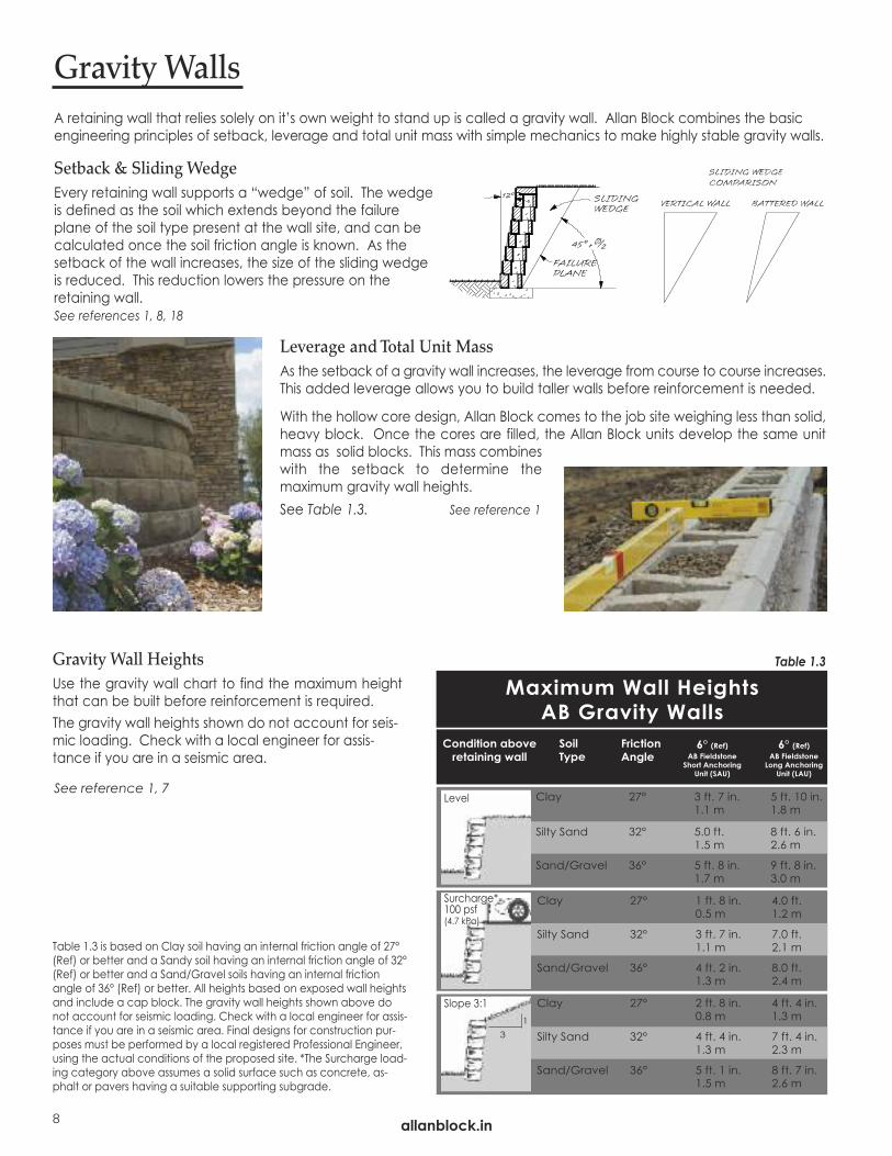
A retaining wall that relies solely on it’s own weight to stand up is called a gravity wall. Allan Block combines the basicengineering principles of setback, leverage and total unit mass with simple mechanics to make highly stable gravity walls.
Leverage and Total Unit MassAs the setback of a gravity wall increases, the leverage from course to course increases.This added leverage allows you to build taller walls before reinforcement is needed.
With the hollow core design, Allan Block comes to the job site weighing less than solid,heavy block. Once the cores are filled, the Allan Block units develop the same unitmass as solid blocks. This mass combineswith the setback to determine themaximum gravity wall heights.See Table 1.3. See reference 1
Gravity Walls
Setback & Sliding WedgeEvery retaining wall supports a “wedge” of soil. The wedgeis defined as the soil which extends beyond the failureplane of the soil type present at the wall site, and can becalculated once the soil friction angle is known. As thesetback of the wall increases, the size of the sliding wedgeis reduced. This reduction lowers the pressure on theretaining wall.See references 1, 8, 18
Condition aboveretaining wall
SoilType
FrictionAngle
6° (Ref)AB FieldstoneShort Anchoring
Unit (SAU)
6° (Ref)AB FieldstoneLong Anchoring
Unit (LAU)
Clay 27° 1 ft. 8 in. 4.0 ft. 0.5 m 1.2 m
Silty Sand 32° 3 ft. 7 in. 7.0 ft.1.1 m 2.1 m
Sand/Gravel 36° 4 ft. 2 in. 8.0 ft.1.3 m 2.4 m
Clay 27° 3 ft. 7 in. 5 ft. 10 in. 1.1 m 1.8 m
Silty Sand 32° 5.0 ft. 8 ft. 6 in.1.5 m 2.6 m
Sand/Gravel 36° 5 ft. 8 in. 9 ft. 8 in.1.7 m 3.0 m
Clay 27° 2 ft. 8 in. 4 ft. 4 in.0.8 m 1.3 m
Silty Sand 32° 4 ft. 4 in. 7 ft. 4 in.1.3 m 2.3 m
Sand/Gravel 36° 5 ft. 1 in. 8 ft. 7 in.1.5 m 2.6 m
Maximum Wall Heights AB Gravity Walls
Table 1.3Gravity Wall HeightsUse the gravity wall chart to find the maximum heightthat can be built before reinforcement is required.The gravity wall heights shown do not account for seis-mic loading. Check with a local engineer for assis-tance if you are in a seismic area.
Level
Surcharge*100 psf(4.7 kPa)
Slope 3:1
31
allanblock.in
Table 1.3 is based on Clay soil having an internal friction angle of 27°(Ref) or better and a Sandy soil having an internal friction angle of 32°(Ref) or better and a Sand/Gravel soils having an internal frictionangle of 36° (Ref) or better. All heights based on exposed wall heightsand include a cap block. The gravity wall heights shown above donot account for seismic loading. Check with a local engineer for assis-tance if you are in a seismic area. Final designs for construction pur-poses must be performed by a local registered Professional Engineer,using the actual conditions of the proposed site. *The Surcharge load-ing category above assumes a solid surface such as concrete, as-phalt or pavers having a suitable supporting subgrade.
See reference 1, 7

Sliding Resistance
FA = Active force on wall = 0.5 (�S) (KA) H2 = 156 lb/ft (2,295 N/m)KA = Active pressure coefficient
W = Total weight of wall = �w (H) (d) = 434 lb/ft (6,639 N/m)FV = Vertical force on wall from retained soils = FA SIN (�W) = 53 lb/ft (785 N/m)FH = Horizontal force on wall from retained soils = FA COS (�W) = 147 lb/ft (2,157 N/m)FR = Force resisting sliding = (W + FV) TAN� = 281 lb/ft (4,130 N/m)
Safety factor against sliding: SFS = FR = 281 lb/ft (4,130 N/m) = 1.91 � 1.5 OKFH 147 lb/ft (2,157 N/m)
2
Sample CalculationAnalyze a gravity wall with the following site conditions:Soil Type = Mixed Silts(�) = 30°Wall Height (H) = 3.44 ft (1.05 m)Batter = 12°Depth of Wall (d) = 0.97 ft (0.3 m)
Overturning ResistanceMO = Overturning moment = FH (0.33) H = 168 ft. lb/ft (754 N-m/m)MR = Moment resisting overturning = (W) [d/2 + 0.5 (H) TAN (90° � �)]
+ (FV) [ d + (0.33) (H) TAN (90°� �)] = 436 ft. lb/ft (1,945 N-m/m)Safety factor against overturning:
SFO = MR = 436 ft. lb/ft (1,945 N-m/m) = 2.6 � 1.5 OKMo 168 ft. lb/ft (754 N-m/m)
CSC (�) SIN (� � �)(SIN (� + �W))1/2 + SIN (� + �W) SIN (� � i) 1/2
SIN (� � i)[ ]( ) == 0.2197
Bearing Capacity�W = Pressure exerted on soil below base block
= (W + FV) / d = 487 lb/ft2 (23,847 Pa)�S = 3000 lb/ft2 (143,640 Pa)Safety factor against bearing failure: FSB =�S = 3,000 lb/ft2 (143,640 Pa) = 6.16 � 2.0 OK
�W 487 lb/ft2 (23,847 Pa)
Gravity Wall AnalysisBefore you analyze any retaining wall make sure you have an accurate picture of the job site conditions. Everyretaining wall must be engineered to withstand the pressure from the soils and other loads behind and above them.Standard gravity wall analysis considers sliding, bearing and overturning forces. On sites with slopes or surcharges, aglobal stability check will also be necessary.
SlidingAbility of the structure toovercome the horizontalforce applied to the wall.Factor of safety = 1.5
OverturningAbility of the structure toovercome the overturningmoment created by therotational forces applied tothe wall.Factor of safety = 1.5
Bearing CapacityAbility of the underlyingsoil to support the weightof the structure.Factor of safety = 2.0
Global StabilityAbility of the internalstrength of the soil tosupport the complete soilmass. Contact localdesign specialist for helpin evaluating your site.
OTHER CONSIDERATIONS: • Slopes • Surcharges • Terraces
Bearing Capacity (�S) = 3000 lb/ft2 (143,640 Pa)Wall Density (�w) = 130 lb/ft3 (2,061 kg/m3)Soil Density (�S) = 120 lb/ft3 (1,923 kg/m3)Factored Friction Angle (�w) = 0.66�Slope Above Wall (i) = 0 Surcharge = None
allanblock.in
allanblock.in
See the Allan Block Engineering Manual for more information.
SYSTEM
KA
9
See reference 1

10
GeogridsGeogrids are flexible, synthetic meshes which are manufacturedspecifically for slope stabilization and earth retention. These“grids” are available in a variety of materials, sizes and strengths.They can be made of high tensile strength plastics or wovenpolyester yarns and are typically packaged at the factory in rolls.The grids are rated by Long-Term Allowable Design Strength(LTADS) with values ranging from 500 to 4,000 pounds per linearfoot (7.3 kN/m to 58.4 kN/m).See reference 1
ConceptWhen wall heights exceed those listed in the gravity wall charton page 8, geogrid can be added to provide a stable wallcondition. Layers of geogrid inserted between the blocks andextending behind the wall interlock with the surrounding soil tocreate a cohesive soil mass. This mass uses its own weight andinternal shear strength to resist both the sliding and theoverturning pressures from the soil being retained. The wall rockin the Allan Block cores provide a positive connection betweenthe layers of geogrid and the Allan Block wall, locking the twosystems together. The reinforced soil mass becomes thestructure and the Allan Block wall becomes the facing. Thespecific location and embedment length of the grid layersdepends upon the site conditions, wall heights and Long-TermAllowable Design Strength of the grid being used. See theapproved plans for exact geogrid locations or consult with alocal engineer.
The Great Wall of China, dating back some 2,200 years,was built as a double sided retaining wall. The soilbetween the two walls was a mixture of clay and gravelreinforced with Tamarisk branches. Allan Block retainingwalls employ “old technology with new materials.”
Reinforced Soil Walls
Positive InterlockAllan Block’s gravel filled hollow core provides a multi-pointinterlock with the grid. As wall heights increase, our exclusive“Rock-Lock” connection, combined with the weight of theAllan Block units, provides the best block-to-grid interlock of anysystem on the market. See the tech sheets on connectiontesting or the Seismic Testing Executive Summary for testingresults on the “Rock-Lock” connection. Connection strengthtesting has been done with our grid manufacturers for results seethe AB Spec Book or AB Engineering Manual.
See reference 1, 2, 3, 13
allanblock.in

allanblock.in11
Design Considerations• Grid strength Select the right strength grid for the job.
Choose LTADS grids from 500 lb/ft to 4000 lb/ft (7.3 kN/m to 58.4 kN/m).
• Embedment length Grid length must extend farenough behind the wall to create a sufficientreinforced gravity mass. Typically a minimum of 60% of total wall height.
• Number of layers Install enough layers to adequatelyincrease the internal strength of the soil mass andhandle all applied loads.
• Spacing between layers Grid layers must be correctlyspaced to distribute internal forces. Typically spacedon 16 in. (405 mm) centers.
• Connection strength Block and geogrid must work together to resist internal forces.
AB Geogrid Wall Typical Section
External StabilityExternal stability exists when the entire wall system - the AllanBlock facing units and the reinforced soil mass - act as a coherentstructure to satisfy standard gravity wall analysis. Proper walldesign must satisfy all four of the following considerations.
BearingSliding GlobalOverturning
Grid Rupture Bulging Internal CompoundPullout
Analysis
Rupture occurs whenexcessive forces exceedthe ultimate tensilestrength of the geogrid.Increase grid strengthor the number of gridlayers
Pullout results whengrid layers are notembedded a sufficientdistance beyond thefailure plane.Increase embedmentlength
Bulging occurs whenhorizontal forcesbetween the geogridlayers causes localizedrotation of the wall.Increase number of grid layers
Internal Compound instabilityoccurs when a slip arc passesthrough retained soil,reinforced soil, and facing.Increase length, strength,or decrease spacing ofgrid, use select infillmaterial
allanblock.in
Internal StabilityInternal stability is the ability of the reinforcement combined withthe internal strength of the soil to hold the soil mass together andwork as a single unit.
Internal Compound StabilitySlip plane that runs through the retained and reinforced soil and wall facing.
SYSTEM
See reference 1, 12, 17
12
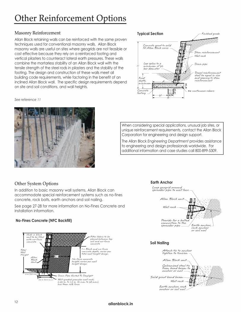
Other System OptionsIn addition to basic masonry wall systems, Allan Block canaccommodate special reinforcement systems such as no-finesconcrete, rock bolts, earth anchors and soil nailing. See page 27-28 for more information on No-Fines Concrete andinstallation information.
Masonry ReinforcementAllan Block retaining walls can be reinforced with the same proventechniques used for conventional masonry walls. Allan Blockmasonry walls are useful on sites where geogrids are not feasible orcost effective because they rely on a reinforced footing andvertical pilasters to counteract lateral earth pressures. These wallscombine the mortarless stability of an Allan Block wall with thetensile strength of the steel rods in pilasters and the stability of thefooting. The design and construction of these walls meet allbuilding code requirements, while factoring in the benefit of aninclined Allan Block wall. The specific design requirements dependon site and soil conditions, and wall heights.
Typical Section
Earth Anchor
Soil Nailing
Other Reinforcement Options
When considering special applications, unusual job sites, orunique reinforcement requirements, contact the Allan BlockCorporation for engineering and design support.The Allan Block Engineering Department provides assistanceto engineering and design professionals worldwide. Foradditional information and case studies call 800-899-5309.
allanblock.in
No-Fines Concrete (NFC Backfill)
See reference 11
Plan and Design an Allan Block project.
13allanblock.in
Develop a Plan 14Design Evaluation 17
PLA
N/D
ES
IGN
PLAN / DESIGN
allanblock.in
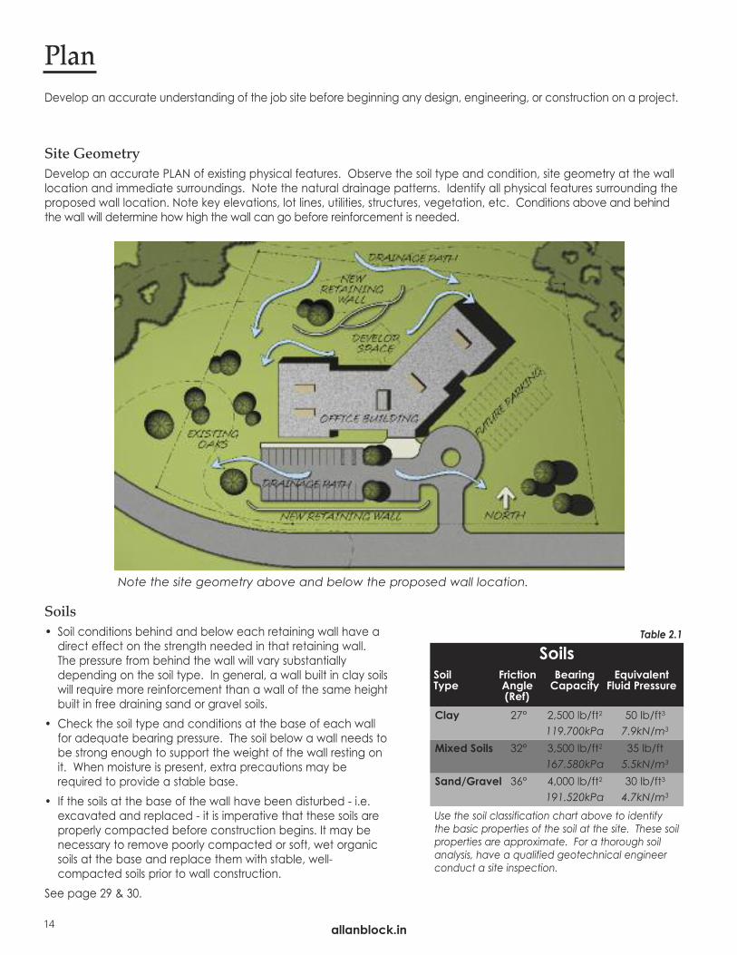
Note the site geometry above and below the proposed wall location.
Site GeometryDevelop an accurate PLAN of existing physical features. Observe the soil type and condition, site geometry at the walllocation and immediate surroundings. Note the natural drainage patterns. Identify all physical features surrounding theproposed wall location. Note key elevations, lot lines, utilities, structures, vegetation, etc. Conditions above and behind the wall will determine how high the wall can go before reinforcement is needed.
Develop an accurate understanding of the job site before beginning any design, engineering, or construction on a project.
Plan
Soils• Soil conditions behind and below each retaining wall have a
direct effect on the strength needed in that retaining wall.The pressure from behind the wall will vary substantiallydepending on the soil type. In general, a wall built in clay soilswill require more reinforcement than a wall of the same heightbuilt in free draining sand or gravel soils.
• Check the soil type and conditions at the base of each wallfor adequate bearing pressure. The soil below a wall needs tobe strong enough to support the weight of the wall resting onit. When moisture is present, extra precautions may berequired to provide a stable base.
• If the soils at the base of the wall have been disturbed - i.e.excavated and replaced - it is imperative that these soils areproperly compacted before construction begins. It may benecessary to remove poorly compacted or soft, wet organicsoils at the base and replace them with stable, well-compacted soils prior to wall construction.
See page 29 & 30.
Use the soil classification chart above to identifythe basic properties of the soil at the site. These soilproperties are approximate. For a thorough soilanalysis, have a qualified geotechnical engineerconduct a site inspection.
Clay 27° 2,500 lb/ft2 50 lb/ft3
119.700kPa 7.9kN/m3
Mixed Soils 32° 3,500 lb/ft2 35 lb/ft167.580kPa 5.5kN/m3
Sand/Gravel 36° 4,000 lb/ft2 30 lb/ft3
191.520kPa 4.7kN/m3
SoilsSoil Friction Bearing EquivalentType Angle Capacity Fluid Pressure
(Ref)
Table 2.1
14 allanblock.in
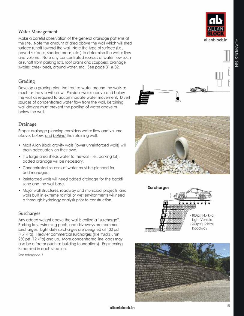
Surcharges
• 100 psf (4.7 kPa)Light Vehicle
• 250 psf (12 kPa)Roadway
Water ManagementMake a careful observation of the general drainage patterns atthe site. Note the amount of area above the wall which will shedsurface runoff toward the wall. Note the type of surface (i.e.,paved surfaces, sodded areas, etc.) to determine the water flowand volume. Note any concentrated sources of water flow suchas runoff from parking lots, roof drains and scuppers, drainageswales, creek beds, ground water, etc. See page 31 & 32.
GradingDevelop a grading plan that routes water around the walls asmuch as the site will allow. Provide swales above and below the wall as required to accommodate water movement. Divertsources of concentrated water flow from the wall. Retaining wall designs must prevent the pooling of water above or below the wall.
DrainageProper drainage planning considers water flow and volumeabove, below, and behind the retaining wall.
• Most Allan Block gravity walls (lower unreinforced walls) willdrain adequately on their own.
• If a large area sheds water to the wall (i.e., parking lot),added drainage will be necessary.
• Concentrated sources of water must be planned for and managed.
• Reinforced walls will need added drainage for the backfillzone and the wall base.
• Major wall structures, roadway and municipal projects, andwalls built in extreme rainfall or wet environments will need a thorough hydrology analysis prior to construction.
SurchargesAny added weight above the wall is called a “surcharge”. Parking lots, swimming pools, and driveways are common surcharges. Light duty surcharges are designed at 100 psf (4.7 kPa). Heavier commercial surcharges (like trucks), run 250 psf (12 kPa) and up. More concentrated line loads may also be a factor (such as building foundations). Engineering is required in each situation.
allanblock.in
allanblock.in
PLA
N/D
ES
IGN
15
See reference 1

SlopesSlopes are measured “run to rise”. A three-to-one slope goes back 3 and up 1.
Slopes AboveSlopes above the wall add more pressure and will require more mass to resist movement. Engineering is required.
Slopes BelowSlopes below the wall may create an unstable foundation.Check with local building codes for length of bench thatmay be required. Engineering is required.
SetbackThe amount the wall leans into the hill is called “setback”. AB units come in multiple setbacks. Bigger setbacks provide better leverage and require less reinforcement. For taller walls use a story pole and level to check for proper setback. Setbacksincrease when walls are built with radii. Comply with constructiontolerances which are found in the AB Spec Book or approvedconstruction plans.
Global StabilityGlobal stability is an engineering analysis of the overall balance of a slope or hillside. Walls built on hillsides mayaffect this balance and stability. Cuts into a hillside will steepenthe effective slope and shift the balance of the hill, thereby re-ducing stability. Walls built on top of slopes have the same effect. Engineering is required.
What to consider when assessing global stability:• Surcharges / Terraced Walls• Slopes• Soil Properties• Water
Slopes Below
Setback
Slopes Above
16
Global Stability
Table 2.2
AB Setback ChartSetback Wall Height
4 ft 6 ft 8 ft 10 ft1.2 m 1.8 m 2.4 m 3.0 m
5.0 in 7.50 in 10.0 in 12.5 in125 mm 190 mm 255 mm 320 mm
AB Fieldstone Collection6°
allanblock.in
All values are provided for reference only.
See reference 1, 18

allanblock.in
allanblock.in
DesignThe design process for a segmental retaining wall typically has aWall Design Engineer or Site Civil Engineer responsible for the walldesign envelope. Geotechnical engineers should be hired toevaluate the overall stability of the site. For information into thebasic concepts behind an Allan Block retaining wall design seeDesign Methods section of the AB Spec Book and Best Practicesfor SRW walls.Proper retaining wall design requires evaluation of the following:
Material and Site Checklist Prior to ConstructionBuilding a reinforced retaining wall requires advanced planning and careful layout at the job site.
Check Your Materials• Cross check the block delivered for color, style and setback, and
confirm it matches the AB unit specified on the approved plans.• Cross check the geogrid delivered for strength, weight, roll size,
strength direction and manufacturer, and confirm it matches the grid specified on the engineered plans.
Delivery and Storage• Lay out a storage area for the block, geogrid reinforcement,
and wall rock. Store blocks on wood pallets and keep the ge-ogrid dry, covered and clean.
• Protect the materials from damage or from coming in contactwith mud, wet concrete, and other contaminating materials.Damaged material should not be incorporated in the project.
1. Select the wall location• Minimize soil excavation and backfill.• Optimize grading and drainage patterns.• Consider existing site features.
2. Determine wall height and geometry• Calculate the wall height at its tallest position.• Identify slopes above and below the wall.• Evaluate surcharges from vehicular or construction traffic.• Select the appropriate wall batter or setback.
3. Evaluate structural requirements• Check the gravity wall table on page 8 for reinforcement requirements.
• If geogrid is required, see page 53 for approximate grid length.
• For projects that fall beyond the scope of the tables inthis manual, refer to the Allan Block Engineering Manual andcontact a qualified engineer.
4. Calculate the total wall structure• Use Table 2.2 to calculate the total wall setback.• Add the required grid lengths to determine total wall envelope.
• Cross check the total wall envelope with available space at wall site.
Note: For more information see the Checklist in the AB Spec Book.
PLA
N/D
ES
IGN
17
18
Wall RockThe proper placement of the wall rock serves several purposes:
• Locks the block and grid together to form a “Rock-Lock”connection.
• Increases the overall weight of each AB Unit, increasingstructural stability.
• Facilitates the compaction process in and around the blocks.• Prevents settlement directly behind the block, which minimizes
additional forces on the grid.
Backfill Soils• On-site soils can be used for backfill around the geogrid
reinforcement only if they meet or exceed the design specifications in the approved plans.
• Heavy expansive clays or organic soils shall not be used in thereinforced zone.
• Where additional fill is required, the contractor shall submit a sample to the wall design engineer or the on-site soils engineer for compliance with the approved plans.
Foundation Soil Preparation• Foundation soil shall be excavated as dimensioned on the
plans and compacted to a minimum of 95% of Standard Proctor prior to placement of the base material.
• Foundation soil shall be examined by the on-site soils engineerto ensure that the actual foundation soil strength meets or exceeds assumed design strength. Soil not meeting the required properties shall be removed and replaced with acceptable material.
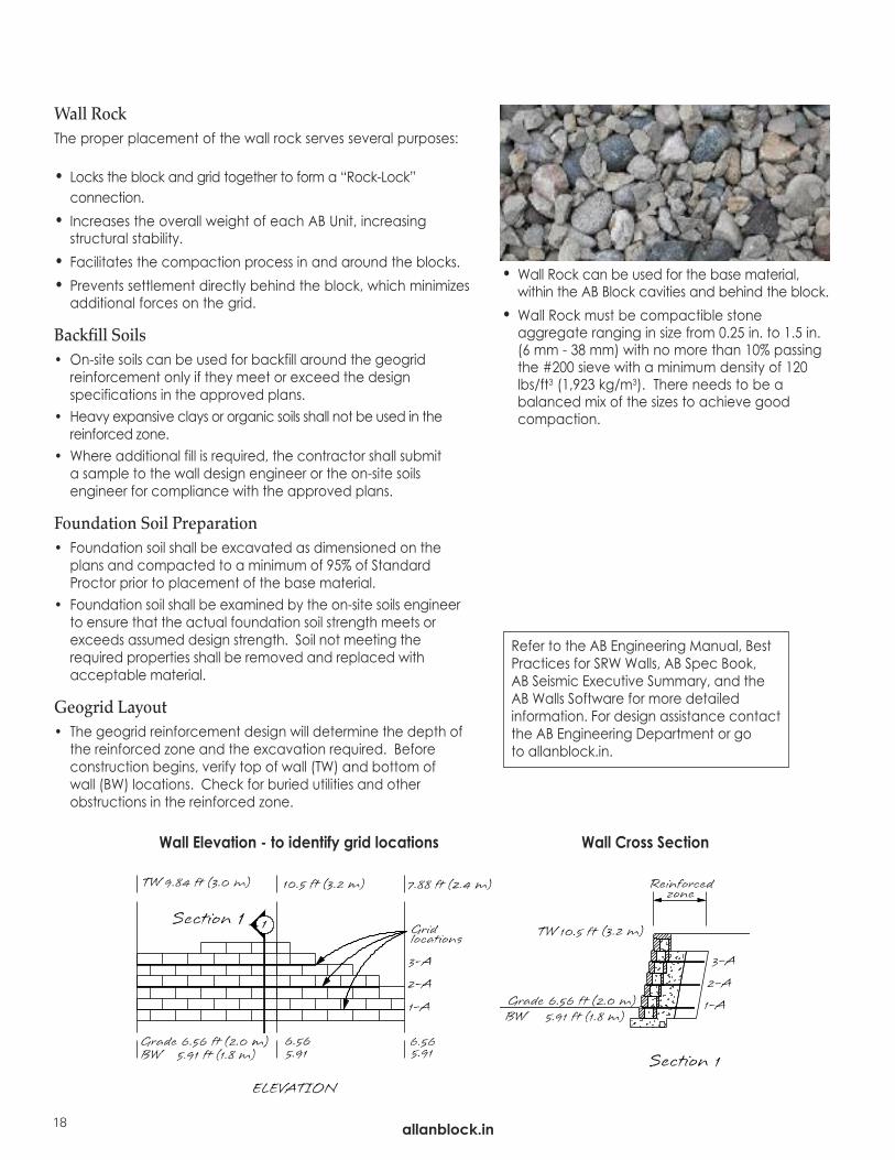
Geogrid Layout• The geogrid reinforcement design will determine the depth of
the reinforced zone and the excavation required. Before construction begins, verify top of wall (TW) and bottom of wall (BW) locations. Check for buried utilities and other obstructions in the reinforced zone.
Wall Cross Section
• Wall Rock can be used for the base material,within the AB Block cavities and behind the block.
• Wall Rock must be compactible stoneaggregate ranging in size from 0.25 in. to 1.5 in.(6 mm - 38 mm) with no more than 10% passingthe #200 sieve with a minimum density of 120lbs/ft3 (1,923 kg/m3). There needs to be abalanced mix of the sizes to achieve goodcompaction.
Wall Elevation - to identify grid locations
Refer to the AB Engineering Manual, BestPractices for SRW Walls, AB Spec Book, AB Seismic Executive Summary, and the AB Walls Software for more detailed information. For design assistance contact the AB Engineering Department or go to allanblock.in.
allanblock.in
allanblock.in
BUILD AB FIELDSTONE®
Installation details for building with the AB Fieldstone retaining wall system.
19allanblock.in
Gravity Wall Construction 22Reinforced Wall Construction 24Working with Geogrid 26No-Fines Conrete Backfill & Installation 27Working with Soils 29Compaction 30Water Management 31
BU
ILD A
B FIE
LDSTO
NE

allanblock.in20
AB Fieldstone® CollectionThe First Eco-Friendly ConcreteRetaining Wall System
Facing Series: SierraColor: Rustic Creek
AB Fieldstone is an innovative new concept in the manufacture and useof segmental retaining wall (SRW) systems. By manufacturing this system in2 pieces - the facing unit and the anchoring unit, Allan Block has openedthe door to many benefits that are not only Green, but Natural andFriendly as well.The facing units are created with differing textures and colors to emulate natural stone, which are referred to as Series. There are currently four Se-ries to choose from: Sierra, Cascade, Colonial and Heritage Series, withadditional ones in development. This product concept provides the po-tential for a variety of new styles and textures. Visit allanblock.in for all thelatest information. The anchoring units are produced with local recycled materials whilemaintaining a beautiful and distinctive look. Manufactured in universalsizes to work with any of the different facing Series, this innovative newproduct has unlimited possibilities.
Anchoring unit -availablein two universal sizes andproduced with local recycled materials.
Facing unit - available indifferent sizes and Seriesstyles. Each Series has varied block faces to ensure a random look,just like you would see in nature.
Some of the facing unitsare manufactured with atextured side eliminatingthe need for extra blockswhen building corners orending walls.
AB Dogbone unit - NEW
The Dogbone units areused to create para-pets in many widths.The parapets can beused to finish off the top of a retaining wallwith seating or plantersor can be built as freestanding walls. See pages 42-43.
allanblock.in
BU
ILD A
B FIE
LDSTO
NE
allanblock.in
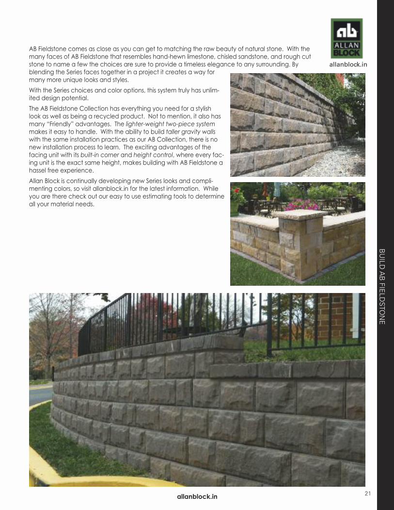
AB Fieldstone comes as close as you can get to matching the raw beauty of natural stone. With themany faces of AB Fieldstone that resembles hand-hewn limestone, chisled sandstone, and rough cutstone to name a few the choices are sure to provide a timeless elegance to any surrounding. Byblending the Series faces together in a project it creates a way formany more unique looks and styles.With the Series choices and color options, this system truly has unlim-ited design potential.The AB Fieldstone Collection has everything you need for a stylishlook as well as being a recycled product. Not to mention, it also hasmany “Friendly” advantages. The lighter-weight two-piece systemmakes it easy to handle. With the ability to build taller gravity wallswith the same installation practices as our AB Collection, there is nonew installation process to learn. The exciting advantages of thefacing unit with its built-in corner and height control, where every fac-ing unit is the exact same height, makes building with AB Fieldstone ahassel free experience.Allan Block is continually developing new Series looks and compli-menting colors, so visit allanblock.in for the latest information. Whileyou are there check out our easy to use estimating tools to determineall your material needs.
21
allanblock.in22
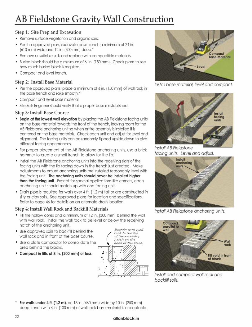
Step 1: Site Prep and Excavation• Remove surface vegetation and organic soils.• Per the approved plan, excavate base trench a minimum of 24 in.
(610 mm) wide and 12 in. (300 mm) deep.* • Remove unsuitable soils and replace with compactible materials.• Buried block should be a minimum of 6 in. (150 mm). Check plans to see
how much buried block is required.• Compact and level trench.
Step 2: Install Base Material• Per the approved plans, place a minimum of 6 in. (150 mm) of wall rock in
the base trench and rake smooth.*• Compact and level base material.• Site Soils Engineer should verify that a proper base is established.
Step 3: Install Base Course • Begin at the lowest wall elevation by placing the AB Fieldstone facing units
on the base material towards the front of the trench, leaving room for theAB Fieldstone anchoring unit so when entire assembly is installed it iscentered on the base materials. Check each unit and adjust for level andalignment. The facing units can be randomly flipped upside down to givedifferent facing appearances.
• For proper placement of the AB Fieldstone anchoring units, use a brickhammer to create a small trench to allow for the lip.
• Install the AB Fieldstone anchoring units into the receiving slots of thefacing units with the lip facing down in the trench just created. Makeadjustments to ensure anchoring units are installed reasonably level withthe facing unit. The anchoring units should never be installed higherthan the facing unit. Except for special applications like corners, eachanchoring unit should match up with one facing unit.
• Drain pipe is required for walls over 4 ft. (1.2 m) tall or are constructed insilty or clay soils. See approved plans for location and specifications.Refer to page 46 for details on an alternate drain location.
Step 4: Install Wall Rock and Backfill Materials• Fill the hollow cores and a minimum of 12 in. (300 mm) behind the wall
with wall rock. Install the wall rock to be level or below the receivingnotch of the anchoring unit.
• Use approved soils to backfill behind thewall rock and in front of the base course.
• Use a plate compactor to consolidate thearea behind the blocks.
• Compact in lifts of 8 in. (200 mm) or less.
* For walls under 4 ft. (1.2 m), an 18 in. (460 mm) wide by 10 in. (250 mm)deep trench with 4 in. (100 mm) of wall rock base material is acceptable.
AB Fieldstone Gravity Wall Construction
Install AB Fieldstone facing units. Level and adjust.
Install AB Fieldstone anchoring units.
Install and compact wall rock andbackfill soils.
Wallrock
Fill void in frontof block
Install anchoringunits
Install facingunits
Compactparallel towall
Install base material, level and compact.
CompactBase Material
Level
allanblock.in
BU
ILD A
B FIE
LDSTO
NE
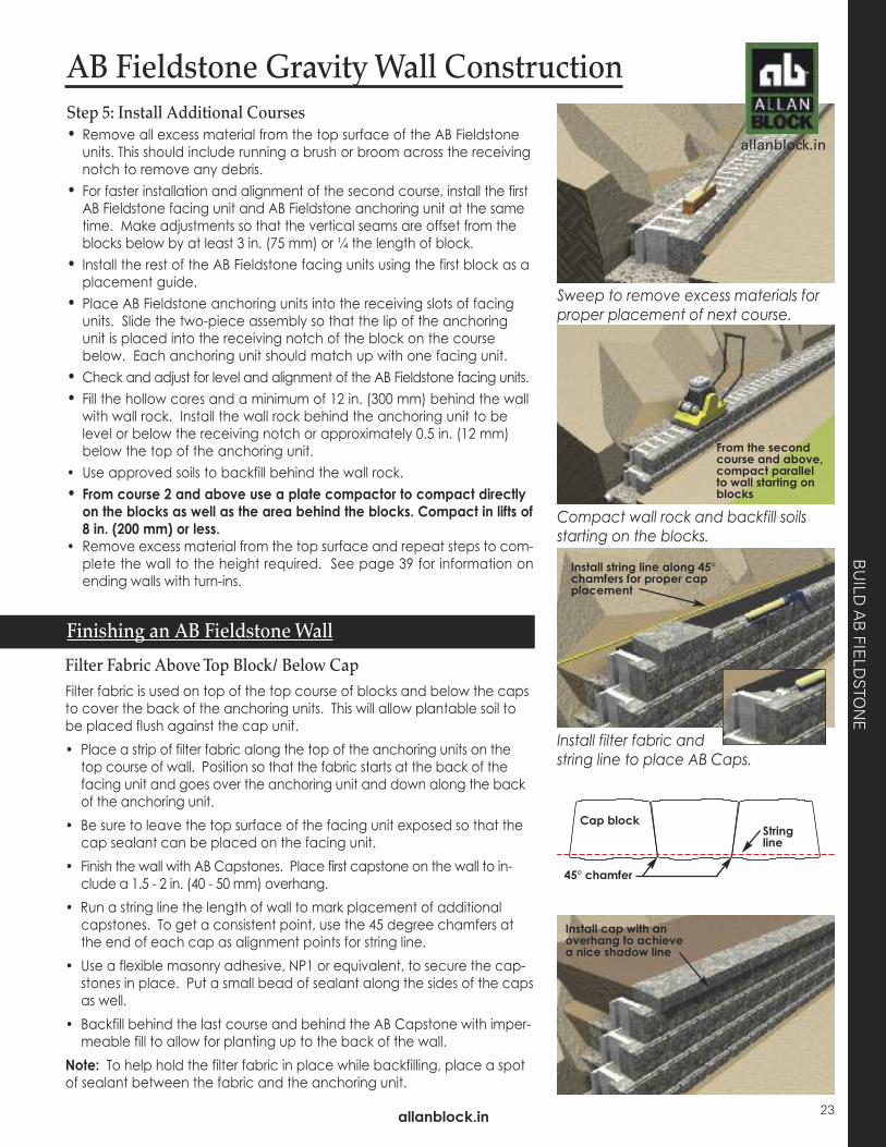
Step 5: Install Additional Courses• Remove all excess material from the top surface of the AB Fieldstone
units. This should include running a brush or broom across the receivingnotch to remove any debris.
• For faster installation and alignment of the second course, install the firstAB Fieldstone facing unit and AB Fieldstone anchoring unit at the sametime. Make adjustments so that the vertical seams are offset from theblocks below by at least 3 in. (75 mm) or ¼ the length of block.
• Install the rest of the AB Fieldstone facing units using the first block as aplacement guide.
• Place AB Fieldstone anchoring units into the receiving slots of facingunits. Slide the two-piece assembly so that the lip of the anchoringunit is placed into the receiving notch of the block on the coursebelow. Each anchoring unit should match up with one facing unit.
• Check and adjust for level and alignment of the AB Fieldstone facing units.• Fill the hollow cores and a minimum of 12 in. (300 mm) behind the wall
with wall rock. Install the wall rock behind the anchoring unit to belevel or below the receiving notch or approximately 0.5 in. (12 mm)below the top of the anchoring unit.
• Use approved soils to backfill behind the wall rock.• From course 2 and above use a plate compactor to compact directlyon the blocks as well as the area behind the blocks. Compact in lifts of8 in. (200 mm) or less.
• Remove excess material from the top surface and repeat steps to com-plete the wall to the height required. See page 39 for information onending walls with turn-ins.
Sweep to remove excess materials forproper placement of next course.
Compact wall rock and backfill soilsstarting on the blocks.
AB Fieldstone Gravity Wall Construction
Filter Fabric Above Top Block/ Below CapFilter fabric is used on top of the top course of blocks and below the capsto cover the back of the anchoring units. This will allow plantable soil tobe placed flush against the cap unit.• Place a strip of filter fabric along the top of the anchoring units on the
top course of wall. Position so that the fabric starts at the back of thefacing unit and goes over the anchoring unit and down along the backof the anchoring unit.
• Be sure to leave the top surface of the facing unit exposed so that thecap sealant can be placed on the facing unit.
• Finish the wall with AB Capstones. Place first capstone on the wall to in-clude a 1.5 - 2 in. (40 - 50 mm) overhang.
• Run a string line the length of wall to mark placement of additionalcapstones. To get a consistent point, use the 45 degree chamfers atthe end of each cap as alignment points for string line.
• Use a flexible masonry adhesive, NP1 or equivalent, to secure the cap-stones in place. Put a small bead of sealant along the sides of the capsas well.
• Backfill behind the last course and behind the AB Capstone with imper-meable fill to allow for planting up to the back of the wall.
Note: To help hold the filter fabric in place while backfilling, place a spotof sealant between the fabric and the anchoring unit.
Finishing an AB Fieldstone Wall
Install filter fabric andstring line to place AB Caps.
From the secondcourse and above,compact parallelto wall starting onblocks
Install string line along 45°chamfers for proper capplacement
Install cap with anoverhang to achievea nice shadow line
allanblock.in
Cap block
45° chamfer
Stringline
23

allanblock.in
AB Fieldstone - Reinforced Wall ConstructionSee page 22 for complete details on proper steps for site prep,drainage requirements and installing the base material for a rein-forced wall. Projects must be built to the approved plans and spec-ifications provided by a local engineer.
Step 1: Install Base Course • Begin at the lowest wall elevation by placing the AB Fieldstone facing units
on the base material towards the front of the trench, leaving room for theAB Fieldstone anchoring unit so when entire assembly is installed it iscentered on the base materials. Install a string line at the back of thefacing unit to ensure the proper positioning of all facing units.
• Adjust for level and alignment as each facing unit is installed. • For proper placement of the AB Fieldstone anchoring units, use a brick
hammer to create a small trench to allow for the lip. • Install the AB Fieldstone anchoring units into the receiving slots of the
facing units with the lip facing down in the trench just created. Makeadjustments to ensure anchoring units are installed reasonably level withthe facing unit. The anchoring units should never be installed higherthan the facing unit. Except for special applications like corners, eachanchoring unit should match up with one facing unit.
• Drain pipe is required for walls over 4 ft. (1.2 m) tall or are constructed insilty or clay soils. See approved plans for location and specifications.Refer to page 46 for details on an alternate drain location.
Step 2: Install Wall Rock and Backfill Materials• Fill the hollow cores of the base course and a minimum of 12 in. (300
mm) behind the wall with wall rock. Install the wall rock to be level orbelow the receiving notch of the anchoring unit, see page 22. Acompactible aggregate ranging in size from 0.25 in. to 1.5 in. (6 mm to38 mm) in diameter, and containing less than 10% fines isrecommended.
• Use approved soils to backfill behind the wall rock and in front of thebase course.
Step 3: CompactCompaction of the material behind the block is critical for a quality wall. • Use a mechanical plate compactor to consolidate the wall rock, then
compact the backfill material immediately behind the block. Compactin a path parallel to the wall, working from the back of the block to theback of the backfill material See page 30 for additional details oncompaction.
• Check the base course for level and adjust as necessary.• All backfill soils must be compacted to a minimum 95% Standard
Proctor. Use equipment appropriate for the soil being compacted.• Remove all excess material from the top surface of all AB units. This
prepares a smooth surface for placement of the next course. This can be assisted when installing the next course of block, by sliding theblock into place.
• Every course after the first course requires compaction starting on the block.
Install AB Fieldstone facing units. Level and adjust.
Install AB Fieldstone anchoring units.
Install wall rock. Compact wall rockand backfill soils.
Sweep to remove excess materials forplacement of geogrid.
24
Wallrock
Infillsoils
Fill void in frontof block
Install anchoringunits
Install facingunits
Compactparallel towall
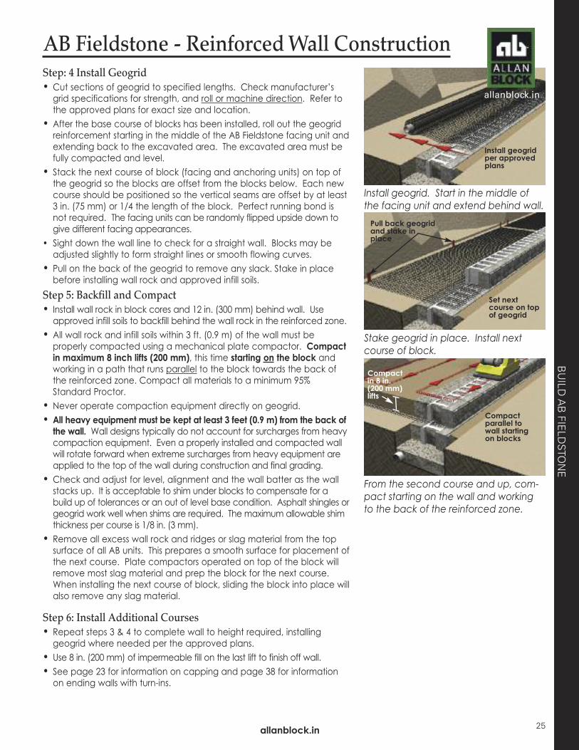
Step: 4 Install Geogrid • Cut sections of geogrid to specified lengths. Check manufacturer’s
grid specifications for strength, and roll or machine direction. Refer tothe approved plans for exact size and location.
• After the base course of blocks has been installed, roll out the geogridreinforcement starting in the middle of the AB Fieldstone facing unit andextending back to the excavated area. The excavated area must befully compacted and level.
• Stack the next course of block (facing and anchoring units) on top ofthe geogrid so the blocks are offset from the blocks below. Each newcourse should be positioned so the vertical seams are offset by at least3 in. (75 mm) or 1/4 the length of the block. Perfect running bond isnot required. The facing units can be randomly flipped upside down togive different facing appearances.
• Sight down the wall line to check for a straight wall. Blocks may beadjusted slightly to form straight lines or smooth flowing curves.
• Pull on the back of the geogrid to remove any slack. Stake in placebefore installing wall rock and approved infill soils.
Step 5: Backfill and Compact• Install wall rock in block cores and 12 in. (300 mm) behind wall. Use
approved infill soils to backfill behind the wall rock in the reinforced zone.• All wall rock and infill soils within 3 ft. (0.9 m) of the wall must be
properly compacted using a mechanical plate compactor. Compactin maximum 8 inch lifts (200 mm), this time starting on the block andworking in a path that runs parallel to the block towards the back ofthe reinforced zone. Compact all materials to a minimum 95%Standard Proctor.
• Never operate compaction equipment directly on geogrid. • All heavy equipment must be kept at least 3 feet (0.9 m) from the back ofthe wall. Wall designs typically do not account for surcharges from heavycompaction equipment. Even a properly installed and compacted wallwill rotate forward when extreme surcharges from heavy equipment areapplied to the top of the wall during construction and final grading.
• Check and adjust for level, alignment and the wall batter as the wallstacks up. It is acceptable to shim under blocks to compensate for abuild up of tolerances or an out of level base condition. Asphalt shingles orgeogrid work well when shims are required. The maximum allowable shimthickness per course is 1/8 in. (3 mm).
• Remove all excess wall rock and ridges or slag material from the topsurface of all AB units. This prepares a smooth surface for placement ofthe next course. Plate compactors operated on top of the block willremove most slag material and prep the block for the next course.When installing the next course of block, sliding the block into place willalso remove any slag material.
Step 6: Install Additional Courses• Repeat steps 3 & 4 to complete wall to height required, installing
geogrid where needed per the approved plans. • Use 8 in. (200 mm) of impermeable fill on the last lift to finish off wall.• See page 23 for information on capping and page 38 for information
on ending walls with turn-ins.
AB Fieldstone - Reinforced Wall Construction
Install geogrid. Start in the middle ofthe facing unit and extend behind wall.
Stake geogrid in place. Install nextcourse of block.
From the second course and up, com-pact starting on the wall and workingto the back of the reinforced zone.
Install geogridper approvedplans
Set nextcourse on topof geogrid
Pull back geogridand stake inplace
Compactparallel towall startingon blocks
Compact in 8 in. (200 mm) lifts
allanblock.in
allanblock.in
BU
ILD A
B FIE
LDSTO
NE
25

Working With Geogrid
Geogrid typically comes in large rolls up to 13 ft (4 m) wide and 250 ft (76 m) in length. These “grids” also come in a vari-ety of weights and strengths. Taller walls often require heavier strength grids, especially in the bottom portions of the wall.
It is critical that the correct grid is installed in the wall. Check the engineered plans and specifications.
Most grids are strongest along the roll or machine direction. Reinforced grid designs require that all grids are placed withthe machine direction running from the face of the wall towards the back of the excavation area.
See page 35-37 for information on using grid with corners and curves.
Use a pair ofgrid stands tohelp measureand cut geogridto requiredlengths.
Machine orroll direction
Machine orroll direction
Front of wallInstall geogrid withthe machine or rolldirection runningfrom the block back into the reinforced zone.
Typical Reinforced Wall Cross Section
Reinforced Wall Structure
Reinforced ZoneThe reinforced zone is located directly behind the block in twosections, the consolidation and the compaction zone. Both zonesrequire compacting in maximum lifts of 8 in. (200 mm), to 95% Standard Proctor. Refer to the specifications in the approved planfor compaction requirements in these zones for each project.
Consolidation ZoneThe consolidation zone runs from the back of the block back 3 ft.(0.9 m) into the infill soil. Only mechanical plate compactionequipment shall be allowed within the consolidation zone.
Compaction ZoneThe compaction zone runs from the back of the consolidation zoneto the cut in the slope. Heavier compaction equipment can be usedin this zone provided no sudden braking or sharp turning occurs.
AB Fieldstone - Reinforced Wall Construction
allanblock.in26

No-Fines Concrete Backfill
No-Fines Concrete (NFC Backfill)
No-Fines ConcreteUse of AB No-Fines Concrete Backfill has increased our ability to in-stall reinforced walls in locations where typical construction wouldnot be possible because of property line constraints or limited ex-cavation options. When using the Allan Block products with No-Fines concrete, the permeable concrete actually attaches to theback of the block and extends the depth of the wall mass. This al-lows for taller walls with less excavation than conventional geogridreinforced walls.Typical geogrid reinforced walls require an excavation depth of 60% or more of the wall height; while a No-Fines reinforced wall,with similar site conditions, requires only 30 to 40% of the wallheight. The recommended minimum structure depth of the No-Fines Concrete Backfill, measured from the face of the wall tothe back of the mass, is 24 in. (60 cm). Limiting the excavationdepth will not only save time and money, but it might make thedifference between getting the job or not. There are additional advantages to using the No-Fines solution.Contractors are able to build with better production rates and withless manpower. The use of No-Fines Concrete Backfill also elimi-nates the need for compaction and compaction testing of the reinforced soil. It provides superior wall drainage since the entiremass is permeable; therefore eliminating the need for wall rock inthe cores and behind the wall. This pervious concrete backfill willprovide a “solid” solution that can reduce the overall settlementbehind the wall.
Engineering Properties:
• No-Fines Concrete Backfill can be used with any of the AllanBlock Retaining Wall Collections.
• No-Fines Concrete Backfill typically consists of cement, fly ash,water and coarse aggregate. The quantity of cementitiousmaterial is approximately 500 lb/yd3 (297 kg/m3) with awater/cement ratio of approximately 0.30 – 0.40.
• No-Fines Concrete Backfill is designed using 3/8 in.to 3/4 in. (9.5 mm to 19 mm) aggregate with an aggregate/cement ratio of 6:1.
• The density of this product will vary with the density of the aggregate used, but will typically range between 100 lb/ft3 –135 lb/ft3 (1600 kg/m3 – 2160 kg/m3).
• No-Fines Concrete Backfill has little to no slump and exerts pressure on the soil and Allan Block wall similar to looselypoured aggregate until cured.
• When using No-Fines Concrete Backfill, the backfill zone will alsoserve as the required drainage or wall rock zone within thecores and directly behind the wall.
allanblock.in
BU
ILD
27
allanblock.in

No-Fines Concrete Installation StepsRefer to the page 22 for the complete installation steps when preparingthe base trench and installing the first course of blocks. Once the firstcourse of blocks are installed and leveled, following these simple steps toplace the No-Fines Concrete Backfill:• Fill all the voids in the block and backfill to the specified depth with theNo-Fines concrete. Obviously, there are numerous ways to get theconcrete mix to the back of the wall. Each site will be different.
• It is recommended, but not required; for straight wall sections, one ofthe back wings of the Allan Block units be removed to help secure theblock face to the concrete backfill.
• The vertical height of a pour should not exceed 16 in. (406 mm) or twocourses of block.
• Additional pours can be made as soon as the No-Fines concretebackfill in the previous lift has set, which is usually not longer than 2 to 3hours. Additional courses of block could be stacked while waiting forthe backfill to cure.
Additional Courses• Brush the top of the blocks to remove any excess material. It isrecommended that this be done before allowing the concrete toharden. Install the next course of blocks ensuring that they are level.Place the No-Fines Concrete Backfill the same way as outlined in theprevious step.
• Continue these steps until the wall reaches its designed height.• It is recommended that a cure time of 2-3 hours is utilized after amaximum of 4 ft (1.2 m) in wall height in installed.
Finishing Options• Use 8-12 in. (200-300 mm) of low permeable fill on the last lift to finish offwall. Place a layer of landscape fabric horizontally above the No-Finesprior to placing the impermeable fill.
• Place a horizontal layer of filter fabric above the no-fines mass prior toplacing low permeable fill above.
• See page 38 for information on ending and topping off the wall.
allanblock.in28
No-Fines Concrete Backfill
No-Fines Chart
Soil Types: Coarse to medium sands, clean sand and gravel, little or no-fines - f = 36°
Soil Types: Uniform to well graded sands, silty sands - f = 32°
Soil Types: Sand-Silt-Clay mix, Clayey sands - f = 27°
Depth of No-Fines including wall facing
Condition Above Wall Wall Height Buried Block
6° (Ref)AB Collection
and AB Fieldstone Collection
6° (Ref)AB Collection
and AB Fieldstone Collection
6° (Ref)AB Collection
and AB Fieldstone Collection
Level SlopeAbove the Wall
ft m in cm ft m ft m ft m
46810
1.21.82.43.0
46810
10152025
-2.534
-0.811.3
-2.53.54
-0.81.11.3
22.53.54.5
0.70.81.11.4
Excerpt from Table 6.2 shown on page 52.

Working with SoilsThe soils used below and behind the wall are a critical part of thetotal wall structure. A reinforced retaining wall is a structure containing three basicbuilding materials - the block facing, the synthetic geogrid reinforcing materials, and the infill materials surrounding the geogrid layers.
SoilsUnderstanding the properties and characteristics of soils is key tobuilding better walls. Different soil types will dictate the amountof time needed for compaction, the amount of reinforcement required, and potentially the cost of the wall.Check the on-site soils carefully before beginning, and get a written identification of the soil type. A soils report from a local engineer will be required before a design and/or permit is issuedfor most walls above 4 ft. (1.2 m). Table 3.1 provides general classification of soils.
Soil SelectionIf the on-site soils are of a very low quality, you should remove andreplace them with better backfill material in the reinforced zoneand the foundation area. The cost of removal will be offset by reduced reinforcement, faster compaction, and better long-termperformance.In the reinforced zone, the type of soil used will determine theamount of grid reinforcement needed. Heavy clays and organicsoils are both unsuitable in the reinforced zone. Generally, any soilwith a friction angle lower than 27° (Ref) or a plasticity index (PI) ofgreater than 20 should be removed and replaced. Soils with frictionangles between 27° (Ref) and 31° (Ref) will require additional care,and attention to water management when placed and com-pacted. This will include extra inspections by an on-site engineer.You must use infill soils that meet or exceed those specified in theengineered specifications and drawings. Have the soils testedbefore placing and compacting.
Typical Friction Angle and Soil Unit WeightsCompacted to 95% Standard Proctor
Soil Type Soil FrictionAngle
Soil Unit Weight (pcf)
Crushed stone, gravel 34° + 110 - 135Clean sands 32 - 34° 100 - 130Silty sands/sandy silt 28 - 30° 110 - 125Sandy clay 26 - 28° 100 - 120Other soils Determined by testing
allanblock.in
allanblock.in
Table 3.1
BU
ILD
29
All soil friction angles and unit weights are provided asreference only and are subject to change based ongeographic area and site conditions.

30
Proper placement and compaction of the infill soils are critical. Com-paction is often measured as a percentage of optimum consolidation ofmaterial being utilized. Foundation and infill soils require compaction to95% of Standard Proctor, or 95% of the soil's maximum density. Local geotechnical and civil engineers are trained to test and measure compaction densities. On-site testing should be part of the wall projectand included in the bid documents. Obtaining the optimum moisturecontent will ensure that the maximum density can be achieved. Soil thatis too dry or too wet will not reach 95% of Standard Proctor.The most important step in getting proper compaction is the placementof the soil in "lifts". Compacting in lifts, or layers, of less than 8 in. (200 mm)will facilitate quality compaction. Compaction equipment must be sizedaccording to the type of material being compacted. Placement andcompaction in lifts that exceed 8 in. (200 mm) will result in less than adequate soil strength. Consult with a local equipment supplier to ensurethat proper compaction equipment is used. Always backfill and com-pact after each course of block is placed.The consolidation zone runs from the back of the block back 3 ft. (0.9 m)into the infill soil. Only walk behind mechanical plate compaction equipment shall be allowed within the consolidation zone. A minimum of two passes with a walk behind plate compactor are required. Con-tinue compaction process until proper compaction is achieved, startingon top of the block and compacting in paths that run parallel with thewall to the back of the consolidation zone. Some applications require higher levels of compaction in the consolida-tion zone. Examples of these include additional walls or structures located within 3 ft (0.9 m) of the back of the wall.Higher levels of compaction can be achieved within the consolidationzone by decreasing the lifts to 4 in. (100 mm) and compacting with walkbehind compaction equipment, starting at the wall facing and running inpaths that run parallel to the wall. Compacting in smaller lifts will achievehigher compaction levels and will not place lateral loads on the wall facing. Multiple passes of the compaction equipment will be required.Higher compaction levels reduce settlement over time.
Correct Compaction Process
Compaction
allanblock.in

The design and performance of most retaining walls arebased on keeping the reinforced zone relatively dry. Toensure that wall structures perform, the construction ofthe wall and layout of the site must be based on maintaining a soil moisture content that is relatively low. Relatively low equates to the moisture content required to achieve desired compaction.Site civil engineering firms utilize a thorough under-standing of the site to determine where water willcome from and how it will be properly managed.Throughout their design process, sources of water aretaken into account to handle above and belowgrade concentrations of water. Contractors must understand the intent of the ap-proved site plans and what will be required to protect the area impacted by the wall construction.Temporary berms may be required to direct wateraway from construction sites.Allan Block walls may be designed with an array of details to ensure that the wall and reinforced soil structure remain free of excess moisture. Basic designdetails mandate toe drains for all walls over 4 ft. (1.2 m) in height, with slopes, or other structures abovethe wall. Once geogrid is introduced into the design,heel drains are also incorporated. In all cases wallrock is located within the cores of the block and aminimum of 12 in. (300 mm) behind the block. Thesethree details are designed to remove incidental waterwithin their respective locations and are not meant asprimary drainage paths for above or below gradewater management. Refer to your approved plans orthe AB Spec Book for specific information on these items.
Water Management
Typical Drain
Drains must be vented to daylight or connected to a storm sewersystem.
All drain pipes must be protected from migration of fine material.Refer to approved plans for construction details.
See page 46 for a cross section drawing of this drain.
allanblock.in
allanblock.in
BU
ILD
31
32
GradingDuring wall layout it is important to evaluate the entire site to determine if water will drain into the area where the walls will be constructed. Using simple berms and swales to divert the wateraround the wall can be easily done. Since walls are often built be-fore the site is completely graded to its final configuration, temporarygrading must be in place to ensure water will not be draining towardsthe construction area. Contact the local engineer of record and thesite civil engineer for directions prior to proceeding with constructionof the wall.
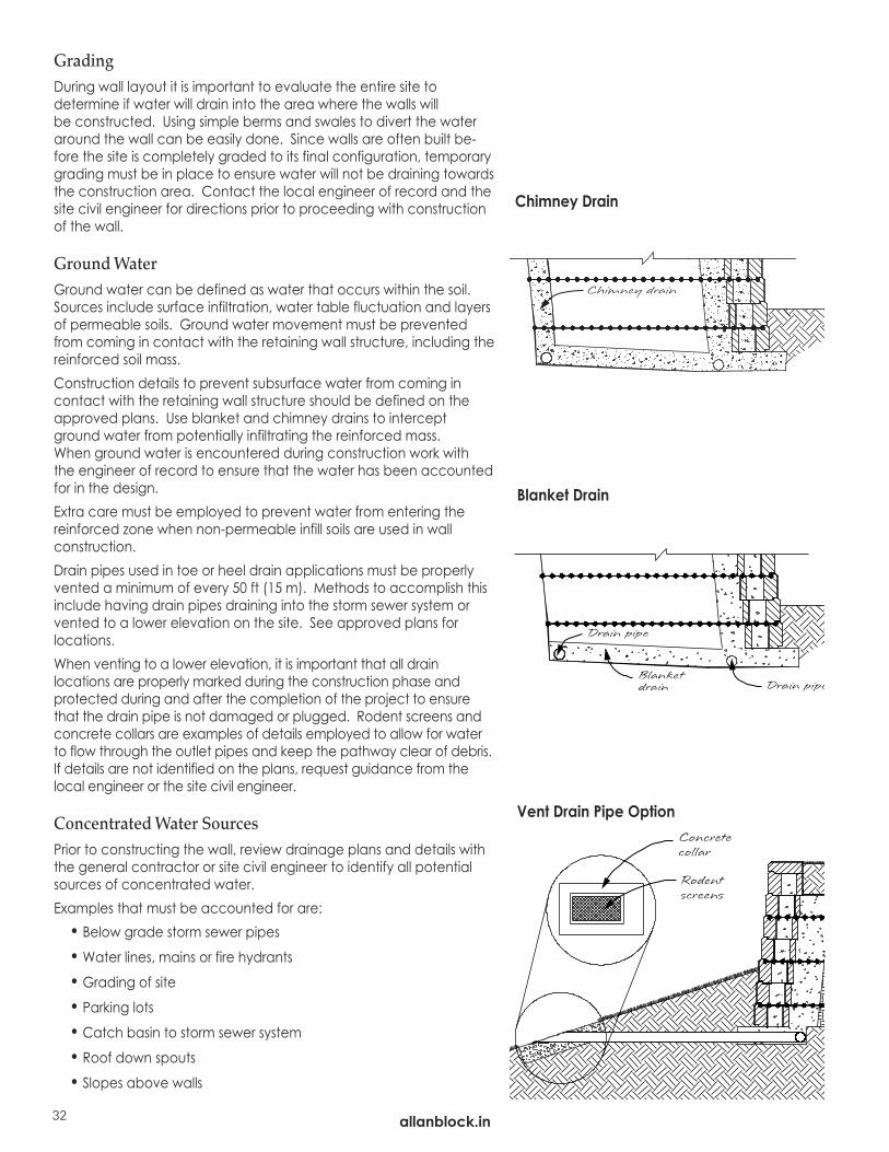
Ground WaterGround water can be defined as water that occurs within the soil.Sources include surface infiltration, water table fluctuation and layersof permeable soils. Ground water movement must be preventedfrom coming in contact with the retaining wall structure, including thereinforced soil mass.Construction details to prevent subsurface water from coming in contact with the retaining wall structure should be defined on theapproved plans. Use blanket and chimney drains to interceptground water from potentially infiltrating the reinforced mass. When ground water is encountered during construction work with the engineer of record to ensure that the water has been accountedfor in the design. Extra care must be employed to prevent water from entering the reinforced zone when non-permeable infill soils are used in wall construction.Drain pipes used in toe or heel drain applications must be properlyvented a minimum of every 50 ft (15 m). Methods to accomplish thisinclude having drain pipes draining into the storm sewer system orvented to a lower elevation on the site. See approved plans for locations.When venting to a lower elevation, it is important that all drain locations are properly marked during the construction phase and protected during and after the completion of the project to ensurethat the drain pipe is not damaged or plugged. Rodent screens andconcrete collars are examples of details employed to allow for waterto flow through the outlet pipes and keep the pathway clear of debris.If details are not identified on the plans, request guidance from thelocal engineer or the site civil engineer.
Concentrated Water SourcesPrior to constructing the wall, review drainage plans and details withthe general contractor or site civil engineer to identify all potentialsources of concentrated water.Examples that must be accounted for are:• Below grade storm sewer pipes
• Water lines, mains or fire hydrants
• Grading of site
• Parking lots
• Catch basin to storm sewer system
• Roof down spouts
• Slopes above walls
Vent Drain Pipe Option
Blanket Drain
Chimney Drain
allanblock.in

CONSTRUCTION DETAILS
Expanded details on building with Allan Block.
allanblock.in
33allanblock.in
Curves 34Curves with Geogrid 35Corners 36Corners with Geogrid 37Finishing Walls 38Stairs 40Parapets 42Terraces 44Design Details 46Construction and Inspection Checklist 48Material Estimate Worksheet 50Geogrid and No-Fines Estimating Charts 52
CO
NSTR
UC
TION
DETA
ILS

Base Course Radius for an outsidecurve on a 4 ft tall 6° wall
Base course radius5 ft 2 in. (1.6 m)
Top course radius4.0 ft (1.2 m)
CenterStake
allanblock.in34
• Removing the “wings” of the blocks will be needed on projects withcurves, corners or step downs. For smooth outside curves, remove oneor both of the “wings” from the back of the anchoring units and tightenthe radius of the curve. Break wings off with a hammer and chisel in theexisting score line to obtain a clean break.
• When working with corners and/or stepping down a wall, split an an-choring unit in half to tie the corner together. Split the block by using ahammer and chisel to make a break down the center of the block.
• On some projects you will need to modify the bottom lip of the block tofit on the course below. Use a hammer and chisel and tap along the lipto remove.
Inside and Outside Curves with AB Fieldstone
Building curved and serpentine walls are simple. AB’s patented design allows for easy installation of both inside and outside curves. For walls requiring geogrid, see page 37.• Try to maintain an offset of the vertical seams by at least 1/4 of the
block length from the courses below for both inside and outside curves.Inside Curves• Place the facing units to form a flowing curve.• Set anchoring units in place with the back of anchoring units fanned
out to form the curve.Outside Curves• Place the facing units to form a flowing curve. • Remove one or both of the wings from the anchoring units to achieve
an outside curve. Then set the anchoring units in place.• See the radius chart to determine the minimum radius for the base
course of an outside curve.
Modifying Anchoring Units
Curves
OutsideCurve
Consistentspacing
Remove wingsfor outsidecurves
Keep the frontof the blocktight together.
Remove wings
InsideCurve
Split anchoringunit in half
Removebottom lip
Working with Radii• Refer to Table 6.1 to confirm that the AB product you are
using will accommodate the desired wall radius.• The tightest or smallest radius at the top of any AB wall usingfull size block is 4 ft. (1.2 m), and 2.5 ft. (0.8 m) using the halfwidth blocks. The final height of the wall will determine whatthe minimum radius at the base course must be. The wallcreates a coning effect as it is stacked up, creating the needfor a larger radius at the base course. Use the Radius Chart todetermine what the radius of the base course of the wallneeds to be, so the top course of the wall will not be less than4 ft. (1.2 m).
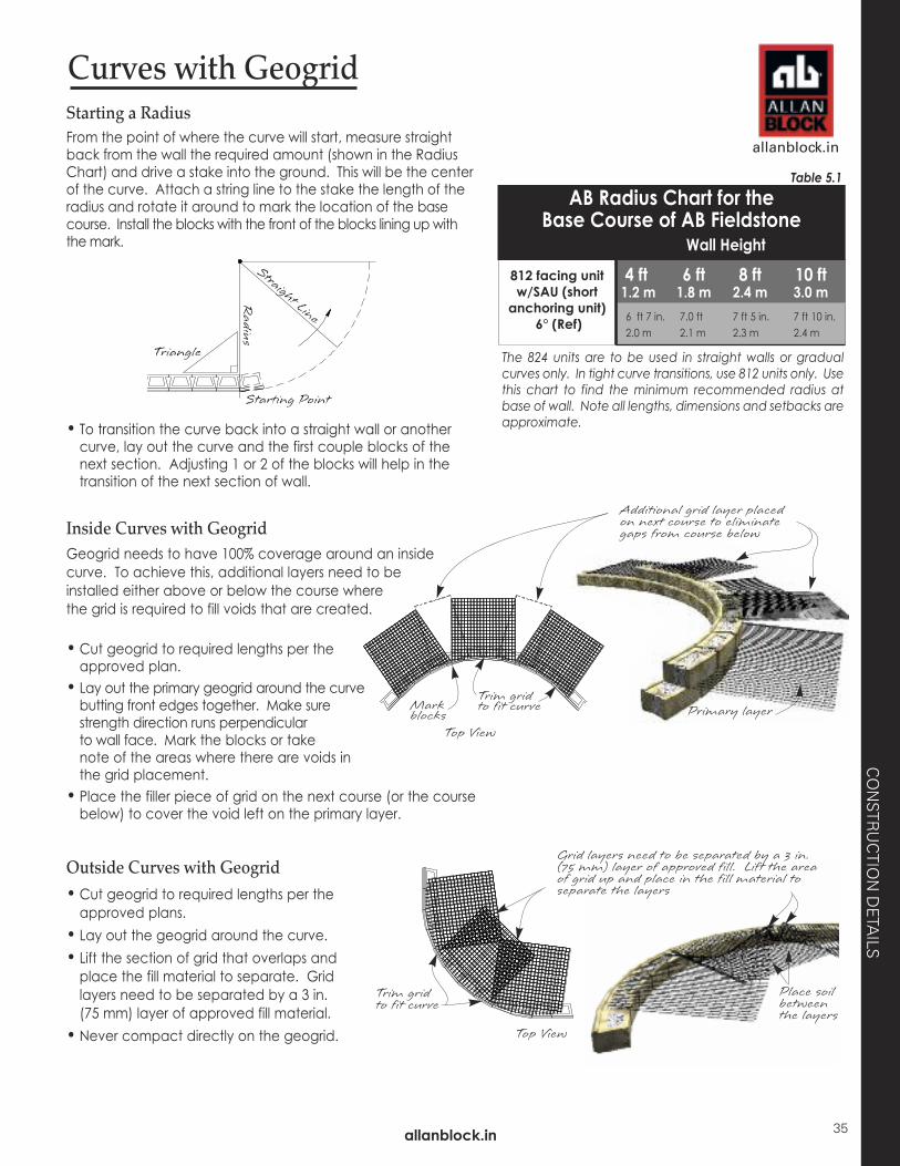
Outside Curves with Geogrid• Cut geogrid to required lengths per theapproved plans.
• Lay out the geogrid around the curve. • Lift the section of grid that overlaps andplace the fill material to separate. Gridlayers need to be separated by a 3 in. (75 mm) layer of approved fill material.
• Never compact directly on the geogrid. Top View
Trim gridto fit curve
Grid layers need to be separated by a 3 in.(75 mm) layer of approved fill. Lift the areaof grid up and place in the fill material toseparate the layers
Place soilbetweenthe layers
Inside Curves with GeogridGeogrid needs to have 100% coverage around an inside curve. To achieve this, additional layers need to be installed either above or below the course where the grid is required to fill voids that are created.
• Cut geogrid to required lengths per theapproved plan.
• Lay out the primary geogrid around the curvebutting front edges together. Make surestrength direction runs perpendicular to wall face. Mark the blocks or take note of the areas where there are voids in the grid placement.
• Place the filler piece of grid on the next course (or the coursebelow) to cover the void left on the primary layer.
Additional grid layer placed on next course to eliminate gaps from course below
Primary layerTrim grid to fit curveMark
blocksTop View
Curves with GeogridStarting a RadiusFrom the point of where the curve will start, measure straightback from the wall the required amount (shown in the RadiusChart) and drive a stake into the ground. This will be the centerof the curve. Attach a string line to the stake the length of theradius and rotate it around to mark the location of the basecourse. Install the blocks with the front of the blocks lining up withthe mark.
• To transition the curve back into a straight wall or anothercurve, lay out the curve and the first couple blocks of thenext section. Adjusting 1 or 2 of the blocks will help in thetransition of the next section of wall.
The 824 units are to be used in straight walls or gradualcurves only. In tight curve transitions, use 812 units only. Usethis chart to find the minimum recommended radius atbase of wall. Note all lengths, dimensions and setbacks areapproximate.
AB Radius Chart for the Base Course of AB Fieldstone
Wall Height
812 facing unitw/SAU (short
anchoring unit)6° (Ref) 6 ft 7 in. 7.0 ft 7 ft 5 in. 7 ft 10 in.
2.0 m 2.1 m 2.3 m 2.4 m
4 ft 6 ft 8 ft 10 ft1.2 m 1.8 m 2.4 m 3.0 m
Table 5.1
allanblock.in
CO
NSTR
UC
TION
DETA
ILS
allanblock.in 35

AB
Extends pastback of blockA’s anchoringunit
Anchoringunit
Extends pastback of blockA’s anchoringunit A
B
Inside and Outside Corners with AB FieldstoneOutside Corners - Some of the AB Fieldstone facing units are manufac-tured with a textured side that compliments the facing unit. Besidesbeing used as a standard block, these blocks can be used to create acorner. To create a left or right hand corner simply flip the facing unit asneeded to change the direction. For walls requiring geogrid, see page 39.• Whenever possible, begin your wall at the corner. Install a facing unit
with the textured end facing out at the corner. Install an additional fac-ing unit perpendicular to create a corner. Install additional facing unitsin both directions to continue down the wall. Check for level. (Step 1)
• Starting at the corner and working out in both directions, use anchoringunits to span the first two facing units in each direction. (Step 2) Both ofthese anchoring units will need to be modified slightly. On the basecourse and above remove the wing from one anchoring unit. Fromcourse two and above, remove part of the lip off the other anchoringunit so that it fits on top of the course below. (Step 3)
• Use half of an anchoring unit on either side of the spanning anchoring unitsto get pattern back to each facing unit having its own anchoring unit.(Step 4)
• Align the lip and notch of the anchoring units in each direction to en-sure proper placement of next wall course.
• Cut caps at 45 degree angles to complete the outside corner and givethe wall a custom finished look.
Inside Corners - By alternating the block’s placement on each course ofthe wall, an inside corner can be installed. The 824 facing units are idealfor this task, but 812 facing units are acceptable. For walls requiring ge-ogrid, see page 39.• To create a 90° inside corner, begin by placing an AB Fieldstone facing
unit (A) at the corner. Then lay a second facing unit (B) perpendicularto the first. This second unit (B) must extend past the back of the firstfacing unit (A). Continue laying out the rest of the base course workingfrom the corner out in both directions. Install the anchoring units.
• On additional courses alternate the placement of the facing units. Re-move the lip from the anchoring unit, where the anchoring unit sits onthe facing unit below as needed.
• Cut caps at 45 degree angles to complete the inside corner and givethe wall a custom finished look.
Corners
Outside Corner Inside Corner
Removelip
Half anchoring units
Removewing
Step 1
Step 2
Step 3
Step 4
Half anchoring units
Remove wingfrom full anchoring unit
1st Course
1st Course
2nd Course
2nd Course
Anchoringunit
allanblock.in36
allanblock.in
CO
NSTR
UC
TION
DETA
ILS
allanblock.in
37
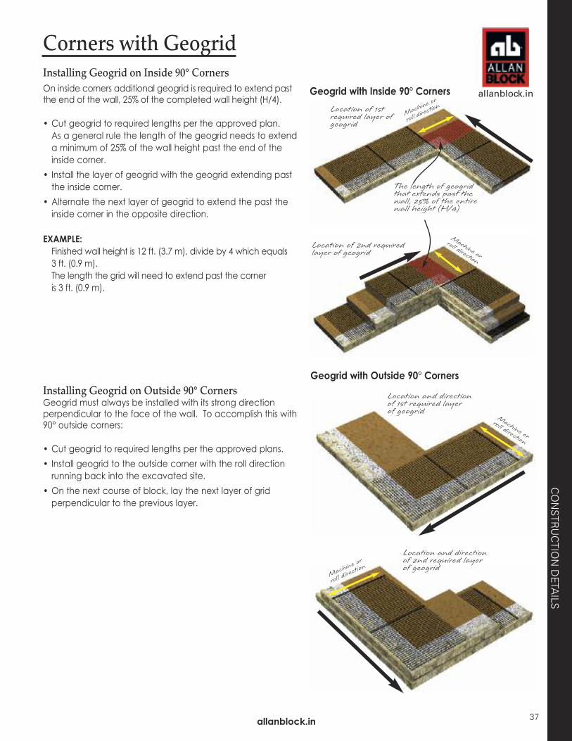
Installing Geogrid on Inside 90° CornersOn inside corners additional geogrid is required to extend pastthe end of the wall, 25% of the completed wall height (H/4).
• Cut geogrid to required lengths per the approved plan. As a general rule the length of the geogrid needs to extenda minimum of 25% of the wall height past the end of theinside corner.
• Install the layer of geogrid with the geogrid extending pastthe inside corner.
• Alternate the next layer of geogrid to extend the past theinside corner in the opposite direction.
EXAMPLE: Finished wall height is 12 ft. (3.7 m), divide by 4 which equals 3 ft. (0.9 m).The length the grid will need to extend past the corner is 3 ft. (0.9 m).
Installing Geogrid on Outside 90° CornersGeogrid must always be installed with its strong directionperpendicular to the face of the wall. To accomplish this with90° outside corners:
• Cut geogrid to required lengths per the approved plans.• Install geogrid to the outside corner with the roll directionrunning back into the excavated site.
• On the next course of block, lay the next layer of gridperpendicular to the previous layer.
Location of 1st required layer of geogrid
Machine o
r
roll dire
ction
Location of 2nd requiredlayer of geogrid
The length of geogridthat extends past thewall, 25% of the entirewall height (H/4)
Machine or
roll direction
Machine or
roll direction
Machine
or
roll dire
ction
Location and directionof 1st required layer of geogrid
Location and directionof 2nd required layerof geogrid
Geogrid with Outside 90° Corners
Geogrid with Inside 90° Corners
Corners with Geogrid
allanblock.in38
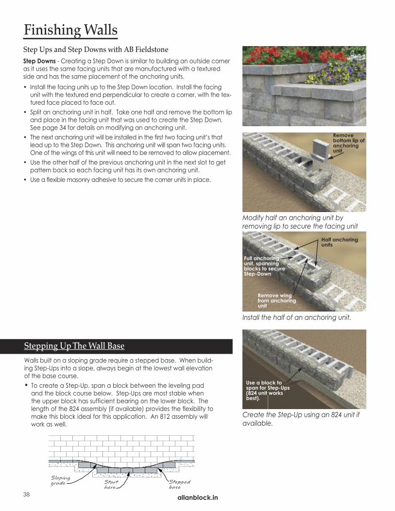
Step Ups and Step Downs with AB FieldstoneStep Downs - Creating a Step Down is similar to building an outside corneras it uses the same facing units that are manufactured with a texturedside and has the same placement of the anchoring units. • Install the facing units up to the Step Down location. Install the facing
unit with the textured end perpendicular to create a corner, with the tex-tured face placed to face out.
• Split an anchoring unit in half. Take one half and remove the bottom lipand place in the facing unit that was used to create the Step Down.See page 34 for details on modifying an anchoring unit.
• The next anchoring unit will be installed in the first two facing unit’s thatlead up to the Step Down. This anchoring unit will span two facing units.One of the wings of this unit will need to be removed to allow placement.
• Use the other half of the previous anchoring unit in the next slot to getpattern back so each facing unit has its own anchoring unit.
• Use a flexible masonry adhesive to secure the corner units in place.
Finishing Walls
Modify half an anchoring unit by removing lip to secure the facing unit
Install the half of an anchoring unit.
Create the Step-Up using an 824 unit ifavailable.
Remove bottom lip ofanchoringunit
Half anchoringunits
Remove wingfrom anchoringunit
Full anchoring unit, spanningblocks to secureStep-Down
Use a block tospan for Step-Ups(824 unit worksbest).
Stepping Up The Wall Base
Walls built on a sloping grade require a stepped base. When build-ing Step-Ups into a slope, always begin at the lowest wall elevationof the base course. • To create a Step-Up, span a block between the leveling pad
and the block course below. Step-Ups are most stable whenthe upper block has sufficient bearing on the lower block. Thelength of the 824 assembly (if available) provides the flexibility tomake this block ideal for this application. An 812 assembly willwork as well.
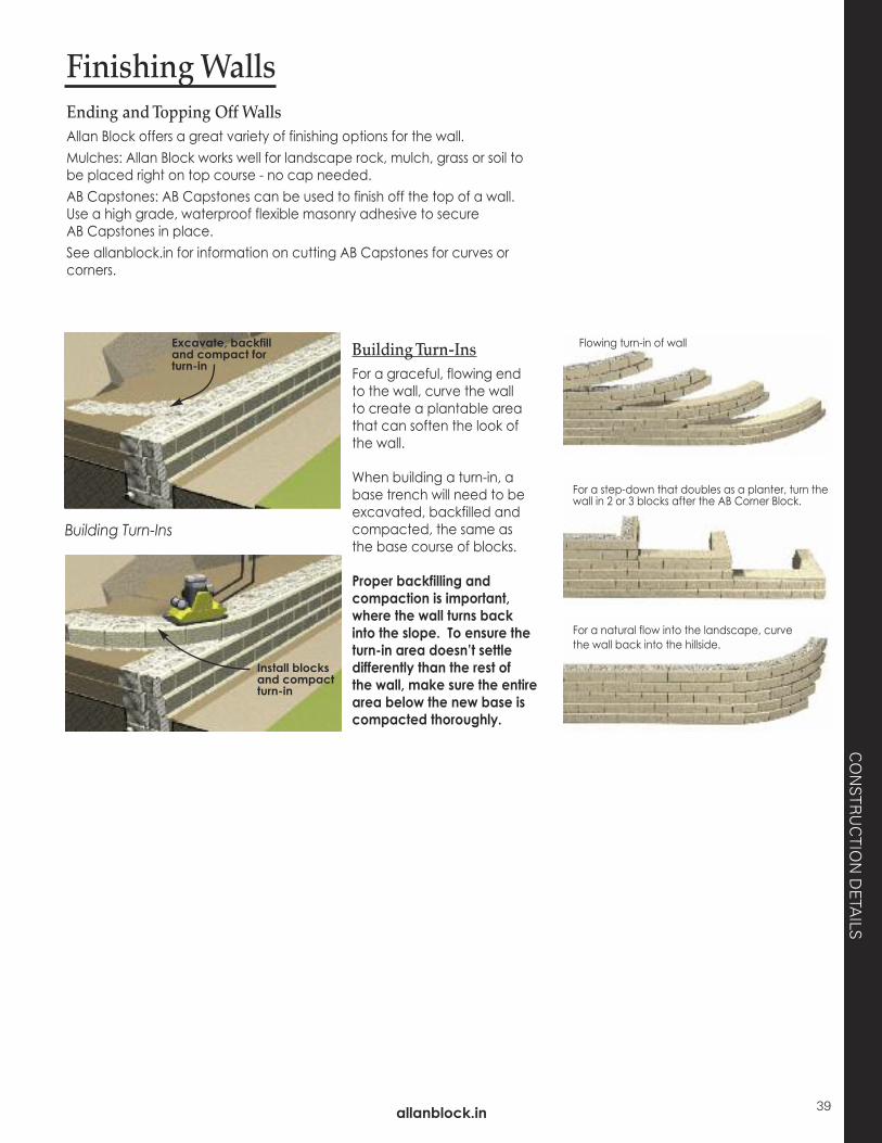
Finishing Walls
For a step-down that doubles as a planter, turn thewall in 2 or 3 blocks after the AB Corner Block.
Ending and Topping Off WallsAllan Block offers a great variety of finishing options for the wall.Mulches: Allan Block works well for landscape rock, mulch, grass or soil tobe placed right on top course - no cap needed.AB Capstones: AB Capstones can be used to finish off the top of a wall.Use a high grade, waterproof flexible masonry adhesive to secure AB Capstones in place. See allanblock.in for information on cutting AB Capstones for curves orcorners.
Building Turn-InsFor a graceful, flowing end to the wall, curve the wall to create a plantable areathat can soften the look ofthe wall.
When building a turn-in, abase trench will need to beexcavated, backfilled andcompacted, the same as the base course of blocks.
Proper backfilling and compaction is important,where the wall turns back into the slope. To ensure theturn-in area doesn’t settle differently than the rest of the wall, make sure the entirearea below the new base iscompacted thoroughly.
For a natural flow into the landscape, curvethe wall back into the hillside.
Excavate, backfilland compact forturn-in
Install blocksand compactturn-in
Building Turn-Ins
Flowing turn-in of wall
CO
NSTR
UC
TION
DETA
ILS
allanblock.in 39

allanblock.in40
StairsStairs can be designed with flowing curves or straightlines. Curved sidewalls create a softer, natural look.Straight sidewalls and corners offer a crisp, traditionalstyle. Allan Block Capstones, pavers, poured con-crete, crushed rock, mulches and flagstone aregood stair tread examples. Ensure that stair treads aresecured in place for safe use.
Additional stair designs and technical information ex-plaining the construction process is available on ourwebsite at allanblock.in or from your local Allan Blockrepresentative. Remember to always check with thelocal codes before construction.
How Many Steps?To find the number of steps needed, measure thetotal rise of your slope in inches (mm) and divideby 8 in. (200 mm) which is the height of a step.
Rise - 48 in. (1220 mm)
48 in. ÷ 8 in. = 6 steps
Long anchoring units
When building stairs, use the long anchoring units (LAU) forthe stair risers when available. This creates a level and sta-ble surface for the treads and additional steps.
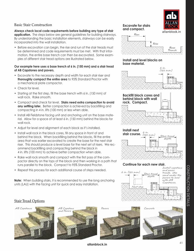
Basic Stair Construction
Always check local code requirements before building any type of stairapplication. The steps below are general guidelines for building stairways.By understanding the basic installation elements, stairways can be easilyincorporated into the wall installation. • Before excavation can begin, the rise and run of the stair treads must
be determined and code requirements must be met. With that infor-mation, the entire base trench can then be excavated. Some exam-ples of different stair tread options are illustrated below.
Our example here uses a base trench of 6 in. (150 mm) and a stair treadof AB Capstones and pavers.• Excavate to the necessary depth and width for each stair riser andthoroughly compact the entire area to 95% Standard Proctor with a mechanical plate compactor.
• Check for level.• Starting at the first step, fill the base trench with 6 in. (150 mm) of
wall rock. Rake smooth. • Compact and check for level. Stairs need extra compaction to avoidany settling later. Better compaction is achieved by backfilling andcompacting in 4 in. lifts (100 mm) or less when able.
• Install AB Fieldstone facing unit and anchoring unit on the base mate-rial. Allow for a space of at least 6 in. (150 mm) behind the blocks forwall rock.
• Adjust for level and alignment of each block as it’s installed.• Install wall rock in the block cores, fill any space in front of and
behind the block. When backfilling behind the blocks, fill the entirearea that was earlier excavated to create the base for the next stairriser. This should produce a level base for the next set of risers. We rec-ommend backfilling and compacting behind the block in 4 in. lifts (100 mm) to achieve better compaction when able.
• Rake wall rock smooth and compact with the first pass of the com-pactor directly on the tops of the block and then working in a path thatruns parallel to the block. Compact to 95% Standard Proctor.
• Repeat this process for each additional course of steps needed.
Note: When building stairs, it is recommended to use the long anchoringunits (LAU) with the facing unit for quick and easy installation.
AB Capstones AB Capstoneand Pavers
Pavers Concrete
Stair Tread Options
Excavate for stairsand compact.
Install and level blocks onbase material.
Backfill block cores andbehind block with wallrock. Compact.
Install nextstair course.
Continue for each new stair.
allanblock.in
allanblock.in
CO
NSTR
UC
TION
DETA
ILS
41
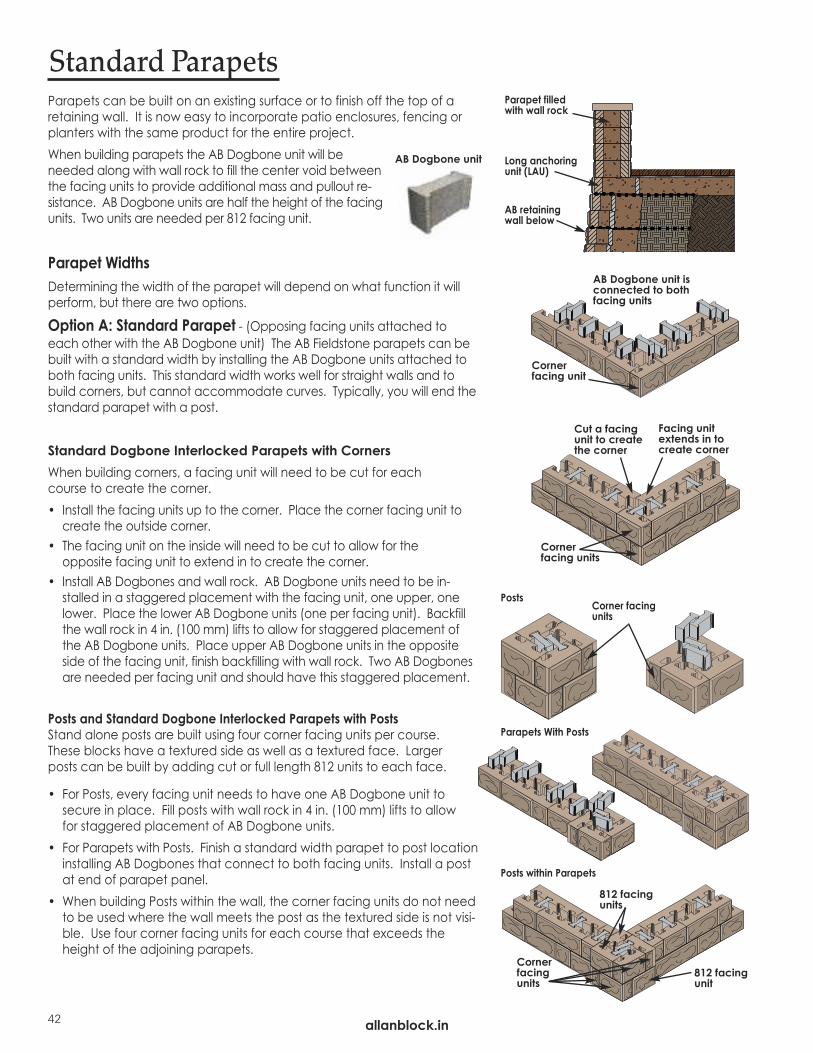
Parapets can be built on an existing surface or to finish off the top of a retaining wall. It is now easy to incorporate patio enclosures, fencing orplanters with the same product for the entire project. When building parapets the AB Dogbone unit will beneeded along with wall rock to fill the center void betweenthe facing units to provide additional mass and pullout re-sistance. AB Dogbone units are half the height of the facingunits. Two units are needed per 812 facing unit.
Parapet WidthsDetermining the width of the parapet will depend on what function it willperform, but there are two options.
Option A: Standard Parapet - (Opposing facing units attached toeach other with the AB Dogbone unit) The AB Fieldstone parapets can bebuilt with a standard width by installing the AB Dogbone units attached toboth facing units. This standard width works well for straight walls and tobuild corners, but cannot accommodate curves. Typically, you will end the standard parapet with a post.
Standard Dogbone Interlocked Parapets with CornersWhen building corners, a facing unit will need to be cut for each course to create the corner.• Install the facing units up to the corner. Place the corner facing unit to
create the outside corner. • The facing unit on the inside will need to be cut to allow for the
opposite facing unit to extend in to create the corner.• Install AB Dogbones and wall rock. AB Dogbone units need to be in-
stalled in a staggered placement with the facing unit, one upper, onelower. Place the lower AB Dogbone units (one per facing unit). Backfillthe wall rock in 4 in. (100 mm) lifts to allow for staggered placement ofthe AB Dogbone units. Place upper AB Dogbone units in the oppositeside of the facing unit, finish backfilling with wall rock. Two AB Dogbonesare needed per facing unit and should have this staggered placement.
Posts and Standard Dogbone Interlocked Parapets with PostsStand alone posts are built using four corner facing units per course.These blocks have a textured side as well as a textured face. Larger posts can be built by adding cut or full length 812 units to each face.
• For Posts, every facing unit needs to have one AB Dogbone unit to secure in place. Fill posts with wall rock in 4 in. (100 mm) lifts to allow for staggered placement of AB Dogbone units.
• For Parapets with Posts. Finish a standard width parapet to post locationinstalling AB Dogbones that connect to both facing units. Install a postat end of parapet panel.
• When building Posts within the wall, the corner facing units do not needto be used where the wall meets the post as the textured side is not visi-ble. Use four corner facing units for each course that exceeds theheight of the adjoining parapets.
Standard Parapets
Corner facing unit
Cut a facingunit to createthe corner
Facing unitextends in tocreate corner
AB Dogbone unit isconnected to bothfacing units
Corner facing units
AB Dogbone unit
Corner facingunits
812 facingunit
Corner facing units
812 facingunits
Long anchoringunit (LAU)
AB retainingwall below
Parapet filledwith wall rock
Posts
Parapets With Posts
Posts within Parapets
allanblock.in42

BU
ILD A
B FIE
LDSTO
NE
allanblock.in
Wider Parapets
Cornerfacingunit
Cut a block tocreate corner
Block extends into create corner
AB Dogbone units do not connect to facing unit behind on wider parapets
Option B: Wider Parapets or Curved Parapets – This option accom-modates any width since the AB Dogbone Units are not connecting the fac-ing units. There are a few widths that make construction easier. A slightlywider parapet that requires no cutting uses two corner blocks to end thewall and works extremely well in straight, corner and curved applications.
Straight Parapets - No Cutting Needed• Begin by placing the AB Fieldstone facing units on the base material or exist-
ing surface. Check for level and alignment.• Install AB Dogbones and wall rock. Stagger the AB Dogbone units, one
up and one down with the facing units to ensure each facing unit hastwo AB Dogbones securing it in place for every course. Install lower ABDogbone units first, then backfill with wall rock in 4 in. (100 mm) lifts.Place upper AB Dogbone units, finish backfilling with wall rock.
• Use care when backfilling with wall rock so facing units do not move outof alignment. External jigs or supports may be required.
Wider Parapets - Ending and CornersTo create a wider parapet end with minimal cutting, we recommend usingtwo 812 corner facing units (A) on odd courses and one cut 824 facing unit(B) on the even courses. However, you can create your own parapet widthbecause the AB Fieldstone parapet can be built with cus-tom spacing between to create a wider planter or bar asexamples.Curved Parapets • When building curved parapets, the parapet must be
wider than the standard parapet application becausethe AB Dogbone units do not line up or attach to both facing units.
• To ensure equal spacing between the facing units remain correct andparallel to each other, level and plumb each course using a tape meas-ure, jig or clamp.
• Stagger the AB Dogbone units, one up and one down with the facingunits to ensure each facing unit has two AB Dogbones securing it in placefor every course.
AAAAB
AB Dogbone units do not connectto facing unit behind
All parapet graphics are to show AB Dog-bone placement. All parapet installationsneed to include wall rock in cores.
allanblock.in 43
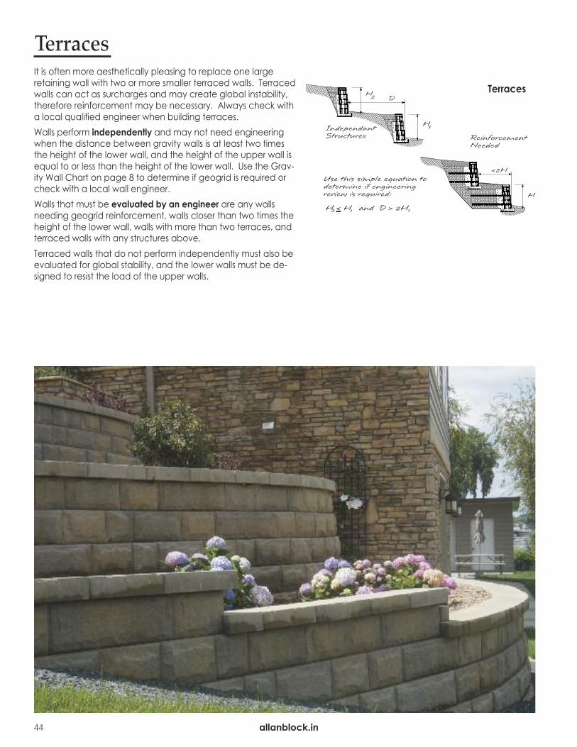
allanblock.in44
It is often more aesthetically pleasing to replace one large retaining wall with two or more smaller terraced walls. Terracedwalls can act as surcharges and may create global instability,therefore reinforcement may be necessary. Always check with a local qualified engineer when building terraces. Walls perform independently and may not need engineeringwhen the distance between gravity walls is at least two timesthe height of the lower wall, and the height of the upper wall isequal to or less than the height of the lower wall. Use the Grav-ity Wall Chart on page 8 to determine if geogrid is required orcheck with a local wall engineer.Walls that must be evaluated by an engineer are any wallsneeding geogrid reinforcement, walls closer than two times theheight of the lower wall, walls with more than two terraces, andterraced walls with any structures above.Terraced walls that do not perform independently must also beevaluated for global stability, and the lower walls must be de-signed to resist the load of the upper walls.
Terraces
Terraces

Water ApplicationsRetaining walls constructed in conditions where there is movingwater (streams), standing water with wave action (lakes), or re-tention ponds are considered water applications. Water applications must be evaluated and designed to fit theunique characteristics of the site. Consult with a local qualifiedengineer for design assistance.
Fences/Guide-RailsThere are several options for installing fences and guide rails ontop of an Allan Block wall. The structure and wind loads of thematerials used will determine the placement of the fence rela-tive to the AB wall and if additional reinforcement is required.Refer to the approved plans for construction details.
LightingAllan Block’s hollow core design makes it easy to install lighting.Cut a hole in the location where the light will be to accommo-date the wiring and attachment of the light to wall face. Carefully follow the manufacturer’s instructions for lighting andelectrical installation, as various fixtures may be assembled differently. Always check local building codes for electrical installation requirements.
Water Application
allanblock.in
allanblock.in
CO
NSTRU
CTIO
N D
E-
Other Applications
45

allanblock.in46
Design DetailsAll drawings are for information only and not for construction. See the approved plans for exact details or contact thelocal engineer of record for written guidance. See allanblock.in for additional details and information.
Typical Reinforced Wall Application Typical Gravity Wall Application
Typical Water Application Swales
Chimney Drain and Blanket Drain Alternate Drain

Wind Bearing Fence or Railing, Option 1 Wind Bearing Fence or Railing, Option 2
Non-Wind Bearing Fence or Railing Double Wall Parapet
Impact Barrier Non Impact Rail
allanblock.in
allanblock.in
47
CO
NSTR
UC
TION
DETA
ILS
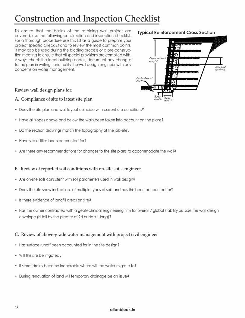
allanblock.in
To ensure that the basics of the retaining wall project are covered, use the following construction and inspection checklist.For a thorough procedure use this list as a guide to prepare yourproject specific checklist and to review the most common points.It may also be used during the bidding process or a pre-construc-tion meeting to ensure that all special provisions are complied with.Always check the local building codes, document any changesto the plan in writing, and notify the wall design engineer with anyconcerns on water management.
Review wall design plans for:
A. Compliance of site to latest site plan
• Does the site plan and wall layout coincide with current site conditions?
• Have all slopes above and below the walls been taken into account on the plans?
• Do the section drawings match the topography of the job-site?
• Have site utilities been accounted for?
• Are there any recommendations for changes to the site plans to accommodate the wall?
B. Review of reported soil conditions with on-site soils engineer
• Are on-site soils consistent with soil parameters used in wall design?
• Does the site show indications of multiple types of soil, and has this been accounted for?
• Is there evidence of landfill areas on site?
• Has the owner contracted with a geotechnical engineering firm for overall / global stability outside the wall designenvelope (H tall by the greater of 2H or He + L long)?
C. Review of above-grade water management with project civil engineer
• Has surface runoff been accounted for in the site design?
• Will this site be irrigated?
• If storm drains become inoperable where will the water migrate to?
• During renovation of land will temporary drainage be an issue?
Construction and Inspection Checklist
48
Typical Reinforcement Cross Section
49
D. Review of below grade water management with wall design engineer and general contractor
• How and where will drain pipe be installed?
• Is it possible to vent drain pipe to daylight?
• Is venting to a storm drainage system an option?
• Will outlets be located and protected from blockage or damage?
E. Surcharges
• Have all surcharges been accounted for?
• During construction are there any temporary surcharges that should be accounted for?
Review Construction Details And Procedures:
A. Mark station points for top and bottom of wall elevation and change in wall direction.B. Identify changes in grid lengths, location of grids, and types of grid to be used.C. Determine and locate proper base size for each section of wall.D. Verify that the correct type and color of block has been ordered and delivered to the job.E. Verify that the foundation soil and retained soil conform to design requirements.F. Verify that infill soil meets design standards.G. Verify that compaction testing will be performed, who is responsible, at what
intervals of locations along the wall, and what coordination will be required.H. Determine what method will be used to verify construction materials, methods, and sequence of
construction. (ie: written documentation of as built, full time inspector on site, photographic documentation.)I. Wall contractor is responsible for quality control of wall installation per the approved plans. The owner or
owner’s representative is responsible for engineering and quality assurance of the project.
Additional Notes:
allanblock.in
allanblock.in
CO
NSTR
UC
TION
DETA
ILS

allanblock.in
Order Materials
Blocks: Ordering block is easy. Use the following steps or visit allanblock.in for helpful estimating tools.
Base and Consolidation Zone: Allan Block recommends using the same material for the base, within the blockcores and behind the blocks. A well-graded (balanced mix of grain sizes) compactible aggregate, 0.25 in. to 1.5 in. (6 mm to 38 mm) diameter with less than 10% fines is needed. Check your local aggregate sources for availability.
These estimates use the minimum amount of material required to build a wall. See the approved plans for exact amounts.
Notes:* Wall height needs to have the amount of buried block included. Buried block should bea minimum of 6 in. (150 mm) or 1 in. (25 mm) for each 1 ft. (0.3 m) of wall height. See theapproved plans to find out what the final height including the buried block will be.
**Extra blocks will need to be included if walls have step ups and/or stairs. Ordering an extra 5% is always recommended to account for any problems during construction.
• See your local Allan Block dealer for exact block dimensions, which need to be used when estimating blocks.
Material Estimation Worksheet
Total LENGTH of wall(s) WIDTH of the block Blocks per coursedivided by(÷)
equals(=)
Total HEIGHT of wall(s)* HEIGHT of block Courses in walldivided by(÷)
equals(=)
multiply (x)
equals (=)
Blocks needed**
ft. (m) ft. (m)
ft. (m) ft. (m)
Total WALL ROCKC). Add the totals from A & B together:
A). Base: The minimum base for a geogrid reinforced retaining wall is: 2 ft. (0.6 m) wide x 0.5 ft (0.15 m) high.
Calculate: 2 ft. (0.6 m) x 0.5 ft (0.15 m) x ft. (m) = ft3 (m3)Width of base Height of base Length of wall Wall Rock
Convert cubic feet (cubic meters) to tons by:
ft3 (m3) x 120 lbs/ft3 (1,923 kg/m3) ÷ 2000 lbs/ton (1000 kg/ton) = Wall Rock Unit weight of rock WALL ROCK IN TONS
B). Block Cores and Consolidation Zone: This includes the material in the block cores plus a 12 in. (300 mm) layerbehind the blocks.
Calculate: ft. (m) x ft. (m) x 1.4 ft. (0.43 m) = ft3 (m3)Wall height Wall length Wall Rock
Convert cubic feet (cubic meters) to tons by: ft3 (m3) x 120 lbs/ft3 (1,923 kg/m3) ÷ 2000 lbs/ton (1000 kg/ton) =
Wall Rock Unit weight of rock WALL ROCK IN TONS
50

51
GeogridUsing the approved plan, contact your local geogrid supplier or Allan Block Representative for geogrid specifications andassistance in ordering materials.
Adhesive for CapstonesUse one 29 ounce tube (820 gm) of adhesive for every 60 ft. (18 m) of wall length where capstones will be installed.
Drain PipeThe length of the wall will usually determine the same amount of drain pipe needed. Check the approved plan forexact specifications and locations of the drain pipe.
Base Material - A base pad of granular material, compacted and leveled to receive the base course of AB units.
Reinforced Zones - Area located directly behind the block that runs to the end of the area being reinforced by any geogrid reinforcement material.
Consolidation Zones - The 3 ft. (0.9 m) area directly behind the back of the block and extending toward the back of the excavated area.
Compaction Zones - The area located behind the consolidationzone that runs to the end of the area being disturbed by anyconstruction activities.
Geogrid - A manufactured high strength reinforcement grid material that comes in rolls of various sizes and strengths.
Infill Soils - The soil used to backfill behind the wall rock in the reinforced zone. These soils need to be identified and approved by a qualified engineer before they can be used. A granular type of material is best.
Drain Pipe - Used to direct incidental water that makes its way in behind the reinforced mass, and vents it to daylight by creat-ing a channel for the water to flow out from.
Wall Rock - Compactible stone aggregate ranging in size from0.25 in to 1.5 in. (6 mm to 38 mm) with no more than 10% fines.Used for base material, within block cores and behind theblock.
Define Terms
Infill SoilsUsing the approved plan, subtract 2 ft (0.6 m) from the grid length required. This figure will determine the depth for theinfill soils. (1 ft (0.3 m) for the block and 1 ft (0.3 m) for the wall rock behind the block)
ft. (m) x Depth area
ft. (m) x ft. (m) x 120 lbs/ft3 (1,923 kg/m3) ÷ 2000 lbs/ton (1000 kg/ton) = kg/tonHeight of wall Length of wall Unit weight of rock Infill soil
AB Capstones ft. (m) ÷ ft. (m) =
Wall length Width of capstone AB Capstones needed
allanblock.in
allanblock.in
CO
NSTR
UC
TION
DETA
ILS
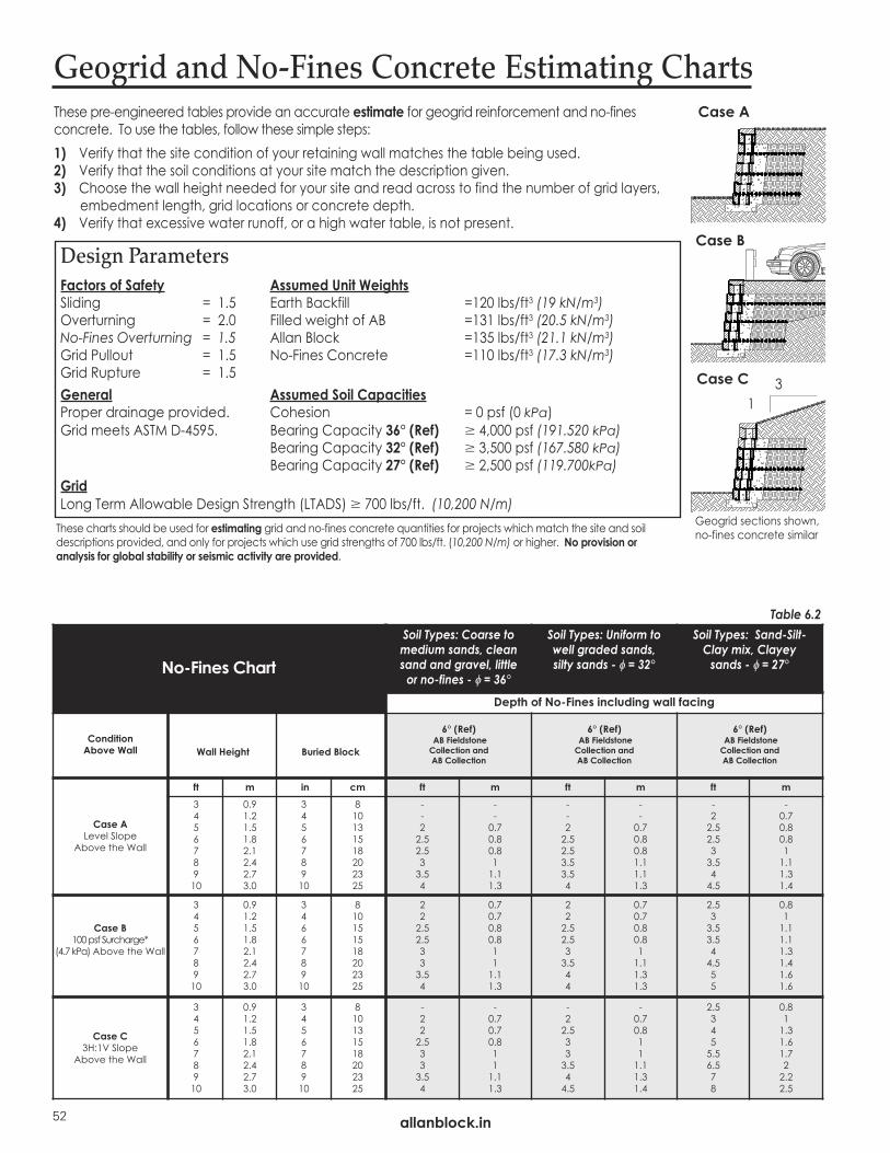
allanblock.in52
Geogrid and No-Fines Concrete Estimating ChartsThese pre-engineered tables provide an accurate estimate for geogrid reinforcement and no-fines concrete. To use the tables, follow these simple steps:1) Verify that the site condition of your retaining wall matches the table being used.2) Verify that the soil conditions at your site match the description given. 3) Choose the wall height needed for your site and read across to find the number of grid layers,
embedment length, grid locations or concrete depth.4) Verify that excessive water runoff, or a high water table, is not present.
Design ParametersFactors of Safety Assumed Unit WeightsSliding = 1.5 Earth Backfill =120 lbs/ft3 (19 kN/m3)Overturning = 2.0 Filled weight of AB =131 lbs/ft3 (20.5 kN/m3)No-Fines Overturning = 1.5 Allan Block =135 lbs/ft3 (21.1 kN/m3)Grid Pullout = 1.5 No-Fines Concrete =110 lbs/ft3 (17.3 kN/m3) Grid Rupture = 1.5General Assumed Soil CapacitiesProper drainage provided. Cohesion = 0 psf (0 kPa)Grid meets ASTM D-4595. Bearing Capacity 36° (Ref) � 4,000 psf (191.520 kPa)
Bearing Capacity 32° (Ref) � 3,500 psf (167.580 kPa)Bearing Capacity 27° (Ref) � 2,500 psf (119.700kPa)
GridLong Term Allowable Design Strength (LTADS) � 700 lbs/ft. (10,200 N/m)These charts should be used for estimating grid and no-fines concrete quantities for projects which match the site and soildescriptions provided, and only for projects which use grid strengths of 700 lbs/ft. (10,200 N/m) or higher. No provision oranalysis for global stability or seismic activity are provided.
Case A
Case B
Case C1
3
No-Fines Chart
Soil Types: Coarse to medium sands, clean sand and gravel, little or no-fines - f = 36°
Soil Types: Uniform to well graded sands, silty sands - f = 32°
Soil Types: Sand-Silt-Clay mix, Clayey sands - f = 27°
Depth of No-Fines including wall facing
Condition Above Wall Wall Height Buried Block
6° (Ref)AB Fieldstone Collection andAB Collection
6° (Ref)AB Fieldstone Collection andAB Collection
6° (Ref)AB Fieldstone Collection andAB Collection
Case ALevel Slope
Above the Wall
ft m in cm ft m ft m ft m345678910
0.91.21.51.82.12.42.73.0
345678910
810131518202325
--22.52.533.54
--0.70.80.811.11.3
--22.52.53.53.54
--0.70.80.81.11.11.3
-22.52.533.544.5
-0.70.80.811.11.31.4
Case B100 psf Surcharge*
(4.7 kPa) Above the Wall
345678910
0.91.21.51.82.12.42.73.0
346678910
810151518202325
222.52.5333.54
0.70.70.80.8111.11.3
222.52.533.544
0.70.70.80.811.11.31.3
2.533.53.544.555
0.811.11.11.31.41.61.6
Case C3H:1V Slope
Above the Wall
345678910
0.91.21.51.82.12.42.73.0
345678910
810131518202325
-222.5333.54
-0.70.70.8111.11.3
-22.5333.544.5
-0.70.8111.11.31.4
2.53455.56.578
0.811.31.61.722.22.5
Table 6.2
Geogrid sections shown,no-fines concrete similar

53
Geogrid Chart AB Fieldstone - 6°
AB Classic - 6°, Patterned Walls - 6°
Soil Types: Coarse to medium sands, clean sand and gravel, little or no-fines - f = 36°
Soil Types: Uniform to well graded sands, silty sands - f = 32°
Soil Types: Sand-Silt-Clay mix, Clayey sands - f = 27°
Condition Above Wall
Wall Height
ft m
BuriedBlock
in cm
# of grid layers
GridLengths
ft m
# of grid layers
GridLengths
ft m
# of grid layers
GridLengths
ft m
Case ALevel Slope
Above the Wall
345678910
0.91.21.51.82.12.42.73.0
366678910
815151518202325
03456778
-3.5455.56.577.5
-1.11.31.61.722.22.3
03456778
-3.5455.56.577.5
-1.11.31.61.722.22.3
23456778
33.5455.56.577.5
11.11.31.61.722.22.3
Case B100 psf Surcharge*
(4.7 kPa) Above the Wall
Top grid layer must extend an extra
3 ft (0.9 m)
345678910
0.91.21.51.82.12.42.73.0
666678910
1515151518202325
23456778
33.5455.56.577.5
11.11.31.61.722.22.3
23456778
33.5455.56.577.5
11.11.31.61.722.22.3
23456779**
33.5455.56.577.5
11.11.31.61.722.22.3
Case C3H:1V Slope
Above the Wall
345678910
0.91.21.51.82.12.42.73.0
366678910
815151518202325
03456778
-3.5455.56.577.5
-1.11.31.61.722.22.3
03456779**
-3.5455.56.577.5
-1.11.31.61.722.22.3
234568**8**10***
33.5455.56.57.58.5
11.11.31.61.722.32.6
The charts below assume for geogrid reinforced walls, that the reinforcement startson the first course of block, and then every second course thereafter. The chartsbelow are for material estimates only, contact your local engineer for wall design. allanblock.in
allanblock.in
CO
NSTR
UC
TION
DETA
ILS
Table 6.3
Note: All walls which require geogrid reinforcement shall have a minimum of 6 in. (150 mm) of buried block. Tables 6.2 and 6.3 are based on Clay soil having an internal friction angle of 27° (Ref) or better and a Sandy soil having an internal friction angle of 32°(Ref) or better and a Sand/Gravel soils having an internal friction angle of 36° (Ref) or better. All setbacks and dimensions are approximate. The wallheights shown do not account for seismic loading. Check with a local engineer for assistance if you are in a seismic area. Final designs for construc-tion purposes must be performed by a local registered Professional Engineer, using the actual conditions of the proposed site. *The Surcharge loading category above assumes a solid surface such as concrete, asphalt or pavers having a suitable supporting subgrade. ** 1 course spacing for first 3 layers of grid. *** 1 course spacing for first 4 layers of grid.
allanblock.in
SECTION 1PART 1: GENERAL1.1 Scope
Work includes furnishing and installing modular concrete block retaining wall units to the lines and grades designated onthe construction drawings and as specified herein.
1.2 Applicable Sections of Related Work Geogrid Wall Reinforcement (See Section 2)
1.3 Reference StandardsA. ASTM C1372 Standard Specification for Segmental Retaining Wall Units.B. ASTM 1262 Evaluating the Freeze Thaw Durability of Manufactured CMU’s and Related Concrete UnitsC. ASTM D698 Moisture Density Relationship for Soils, Standard MethodD. ASTM D422 Gradation of SoilsE. ASTM C140 Sample and Testing Concrete Masonry Units
1.4 Delivery, Storage, and HandlingA. Contractor shall check the materials upon delivery to assure proper material has been received.B. Contractor shall prevent excessive mud, cementitious material, and like construction debris from coming in contact
with the materials.C. Contractor shall protect the materials from damage. Damaged material shall not be incorporated in the project
(ASTM C1372).1.5 Contractor Requirements
Contractors shall be trained and certified by local manufacturer or equivalent accredited organization.A. Allan Block and NCMA have certification programs that are accredited. Identify when advanced certification levels
are appropriate based on complexity and criticality of project application. B. Contractors shall provide a list of projects they have completed.
PART 2: MATERIALS2.1 Modular Wall UnitsA. Wall units shall be Allan Block Retaining Wall units as produced by a licensed manufacturer.B. Wall units shall have minimum 28 day compressive strength of 3000 psi (20.7 MPa) in accordance with ASTM C1372.
The concrete units shall have adequate freeze-thaw protection in accordance with ASTM C1372 or an average ab-sorption rate of 7.5 lb/ft³ (120 kg/m³) for northern climates and 10 lb/ft³ (160 kg/m³) for southern climates.
C. Exterior dimensions shall be uniform and consistent. Maximum dimensional deviations on the height of any two unitsshall be 0.125 in. (3 mm).
D. Wall units shall provide a minimum of 110 lbs total weight per square foot of wall face area (555 kg/m²). Hollow coresto be filled with wall rock and compacted by using plate compactor on top of wall units (see section 3.4). Unit weightof wall rock in cores may be less than 100% depending on compacted base.
E. Exterior face shall be textured. Color as specified by owner. F. Freeze Thaw Durability: Like all concrete products, dry-cast concrete SRW units are susceptible to freeze-thaw degra-
dation with exposure to de-icing salts and cold temperature. This is a concern in northern tier states that use deicingsalts. Based on good performance experience by several agencies, ASTM C1372, Standard Specification for Segmen-tal Retaining Wall Units should be used as a model, except that the compressive strength for the units should be in-creased to a minimum of 4,000 – 5,800 psi (28 - 40 MPa) unless local requirements dictate higher levels. Also,maximum water absorption should be reduced and requirements for freeze-thaw testing increased.
a. Require a current passing ASTM C1262 or equivalent governing standard or public authority, test report from material supplier in northern or cold weather climates.
b. See the Best Practices for SRW Design document for detailed information on freeze thaw durability testing cri-teria and regional temperature and exposure severity figures and tables to define the appropriate zone and requirements for the project.
2.2 Wall RockA. Material must be well-graded compactible aggregate, 0.25 in. to 1.5 in., (6 mm-38 mm) with no more than 10% pass-
ing the #200 sieve. (ASTM D422)B. Material behind and within the blocks may be the same material.
2.3 Infill SoilA. Infill material shall be site excavated soils when approved by the on-site soils engineer unless otherwise specified in
the drawings. Unsuitable soils for backfill (heavy clays or organic soils) shall not be used in the reinforced soil mass.Fine grained cohesive soils [�<31° (Ref)] may be used in wall construction, but additional backfilling, compaction and
Specification Guidelines: Allan Block Modular Retaining Wall Systems
54

55allanblock.in
SP
EC
IFICATIO
NS
water management efforts are required. Poorly graded sands, expansive clays and/or soils with aplasticity index (PI) >20 or a liquid limit (LL) >40 should not be used in wall construction.
B. The infill soil used must meet or exceed the designed friction angle and description noted on thedesign cross sections, and must be free of debris and consist of one of the following inorganicUSCS soil types: GP, GW, SW, SP, GP-GM or SP-SM meeting the following gradation as determined in accordance with ASTM D422.
C. Where additional fill is required, contractor shall submit sample and specifi-cations to the wall design engineer or the on-site soils engineer for approvaland the approving engineer must certify that the soils proposed for use hasproperties meeting or exceeding original design standards.
PART 3: WALL CONSTRUCTION3.1 Excavation
A. Contractor shall excavate to the lines and grades shown on the construction drawings. Contractor shall use cautionnot to over-excavate beyond the lines shown, or to disturb the base elevations beyond those shown.
B. Contractor shall verify locations of existing structures and utilities prior to excavation. Contractor shall ensure all sur-rounding structures are protected from the effects of wall excavation.
3.2 Foundation Soil PreparationA. Foundation soil shall be defined as any soils located beneath a wall.B. Foundation soil shall be excavated as dimensioned on the plans and compacted to a minimum of 95% of Standard
Proctor (ASTM D698) prior to placement of the base material.C. Foundation soil shall be examined by the on-site soils engineer to ensure that the actual foundation soil strength
meets or exceeds assumed design strength. Soil not meeting the required strength shall be removed and replacedwith acceptable material.
3.3 BaseA. The base material shall be the same as the Wall Rock material (Section 2.2) or a low permeable granular material.B. Base material shall be placed as shown on the construction drawing. Top of base shall be located to allow bottom
wall units to be buried to proper depths as per wall heights and specifications.C. Base material shall be installed on undisturbed native soils or suitable replacement fills compacted to a minimum of
95% Standard Proctor (ASTM D698).D. Base shall be compacted at 95% Standard Proctor (ASTM D698) to provide a level hard surface on which to place
the first course of blocks. The base shall be constructed to ensure proper wall embedment and the final elevationshown on the plans. Well-graded sand can be used to smooth the top 1/2 in. (13 mm) on the base material.
E. Base material shall be a 4 in. (100 mm) minimum depth for walls under 4 ft (1.2 m) and a 6 in. (150 mm) minimumdepth for walls over 4 ft (1.2 m).
3.5 Unit InstallationA. The first course of wall units shall be placed on the prepared base per the manufacturers installation recommenda-
tions. The units shall be checked for level and alignment as they are placed.B. Ensure that units are in full contact with base. Proper care shall be taken to develop straight lines and smooth curves
on base course as per wall layout.C. Fill all cores and cavities and a minimum of 12 in. (300 mm) behind the base course with wall rock. Use infill soils be-
hind the wall rock and approved soils in front of the base course to firmly lock in place. Check again for level andalignment. Use a plate compactor to consolidate the area behind the base course. All excess material shall beswept from top of units.
D. Install next course of wall units on top of base course. Position blocks to be offset from seams of blocks below. Perfect "run-ning bond" is not essential, but a 3 in. (75 mm) minimum offset is recommended. Check each block for proper alignmentand level. Fill all cavities in and around wall units and to a minimum of 12 in. (300 mm) depth behind block with wall rock.Wall rock and infill soil placed in uniform lifts not exceeding 8 in. (200 mm). Compaction requirements for all soils in areasin, around and behind the reinforced mass shall be compacted to 95% of maximum Standard Proctor dry density (ASTMD698) with a moisture content control of +1% to -3% of optimum.
E. For taller wall applications, structural fill should be specified for a minimum bottom 1/3 to 1/2 of the reinforced fill. Ifstructural fill is not utilized in the reinforced mass, the depth of wall rock behind the block should be increased. Seethe Best Practices for SRW Design document.
F. The consolidation zone shall be defined as 3 ft (0.9 m) behind the wall. Compaction within the consolidation zone shall beaccomplished by using a hand operated plate compactor and shall begin by running the plate compactor directly onthe block and then compacting in parallel paths from the wall face until the entire consolidation zone has been com-pacted. A minimum of two passes of the plate compactor are required with maximum lifts of 8 in. (200 mm). Expansive
allanblock.in
Sieve Size Percent Passing1 in (25 mm) 100 - 75
No. 4 100 - 20No. 40 0 - 60No. 200 0 - 35

allanblock.in56
or fine-grained soils may require additional compaction passes and/or specific compaction equipment such as asheepsfoot roller. Maximum lifts of 4 in. (100 mm) may be required to achieve adequate compaction within the con-solidation zone. Employ methods using lightweight compaction equipment that will not disrupt the stability or batterof the wall. Final compaction requirements in the consolidation zone shall be established by the engineer of record.
G. Install each subsequent course in like manner. Repeat procedure to the extent of wall height.H. As with any construction work, some deviation from construction drawing alignments will occur. Variability in construction
of SRWs is approximately equal to that of cast-in-place concrete retaining walls. As opposed to cast-in-place concretewalls, alignment of SRWs can be simply corrected or modified during construction. Based upon examination of numerouscompleted SRWs, the following recommended minimum tolerances can be achieved with good construction techniques.(see the pg 19 of AB Spec Book).Vertical Control - ±1.25 in. (32 mm) max. over 10 ft (3 m) distance.Horizontal Location Control - straight lines ±1.25 in. (32 mm) over a 10 ft (3 m) distance.Rotation - from established plan wall batter : ±2.0°
3.6 Additional Construction NotesA. When one wall branches into two terraced walls, it is important to note that the soil behind the lower wall is also the
foundation soil beneath the upper wall. This soil shall be compacted to a minimum of 95% of Standard Proctor (ASTMD698) prior to placement of the base material. Achieving proper compaction in the soil beneath an upper terraceprevents settlement and deformation of the upper wall. One way is to replace the soil with wall rock and compact in8 in. (200 mm) lifts. When using on-site soils, compact in maximum lifts of 4 in. (100 mm) or as required to achievespecified compaction.
B. Vertical filter fabric use is not suggested for use with cohesive soils. Clogging of such fabric creates unacceptable hy-drostatic pressures in soil reinforced structures. When filtration is deemed necessary in cohesive soils, use a three dimen-sional filtration system of clean sand or filtration aggregate. Vertical filter fabric may be used to separate wall rock zonefrom fine grained, sandy infill soils if the design engineer deems it necessary based on potential water migration fromabove or below grade, through the reinforced zone into the wall rock on the project. Horizontal filter fabric should beplaced above the wall rock column to prevent soils from above migrating into the wall rock column.
C. Embankment protection fabric is used to stabilize rip rap and foundation soils in water applications and to separateinfill materials from the retained soils. This fabric should permit the passage of fines to preclude clogging of the mate-rial. Embankment protection fabric shall be a high strength polypropylene monofilament material designed to meetor exceed typical Corps of Engineers plastic filter fabric specifications (CW-02215); stabilized against ultraviolet (UV)degradation and typically exceeding the values on Table 1. (see the Water Management section of AB Spec Book).
D. Water management is of extreme concern during and after construction. Steps must be taken to ensure that drainpipes are properly installed and vented to daylight or connected to an underground drainage system and a gradingplan has been developed that routes water away from the retaining wall location. Site water management is re-quired both during construction of the wall and after completion of construction.
Consult the Allan Block Engineering Department for details 800-899-5309.A specification subject to change without notice, this document was last updated on 4/21/2015.
Geogrid Reinforcement SystemsSECTION 2PART 1: GENERAL1.1 ScopeWork includes furnishings and installing geogrid reinforcement, wall block, and backfill to the lines andgrades designated on the construction drawings and as specified herein.
1.2 Applicable Section of Related WorkSection 1: Allan Block Modular Retaining Wall Systems. (See Section 1)
1.3 Reference StandardsSee specific geogrid manufacturers reference standards.
Additional Standards:A. ASTM D4595 - Tensile Properties of Geotextiles by the Wide-Width Strip MethodB. ASTM D5262 - Test Method for Evaluating the Unconfined Creep Behavior of GeogridsC. ASTM D6638 Grid Connection Strength (SRW-U1)D. ASTM D6916 SRW Block Shear Strength (SRW-U2)E. GRI-GG4 - Grid Long Term Allowable Design Strength (LTADS)F. ASTM D6706 - Test Method for Geogrid Pullout
1.4 Delivery, Storage, and HandlingA. Contractor shall check the geogrid upon delivery to assure that the proper material has been received.B. Geogrid shall be stored above -10° F (-23° C).C. Contractor shall prevent excessive mud, cementitious materials, or other foreign materials from coming in contact
with the geogrid material.PART 2: MATERIALS2.1 DefinitionsA. Geogrid products shall be of high density polyethylene or polyester yarns encapsulated in a protective coating
specifically fabricated for use as a soil reinforcement material.B. Concrete retaining wall units are as detailed on the drawings and shall be Allan Block Retaining Wall Units.C. Drainage material is free draining granular material as defined in Section 1, 2.2 Wall Rock.D. Infill soil is the soil used as fill for the reinforced soil mass.E. Foundation soil is the in-situ soil.
2.2 ProductsGeogrid shall be the type as shown on the drawings having the property requirements as described within the manufac-turers specifications.
2.3 Acceptable ManufacturersA manufacturer’s product shall be approved by the wall design engineer.
PART 3: WALL CONSTRUCTION3.1 Foundation Soil PreparationA. Foundation soil shall be excavated to the lines and grades as shown on the construction drawings, or as directed by
the on-site soils engineer.B. Foundation soil shall be examined by the on-site soils engineer to assure that the actual foundation soil strength
meets or exceeds assumed design strength.C. Over-excavated areas shall be filled with compacted backfill material approved by on-site soils engineer.D. Contractor shall verify locations of existing structures and utilities prior to excavation. Contractor shall ensure all sur-
rounding structures are protected from the effects of wall excavation.3.2 Wall ConstructionWall construction shall be as specified under Section 1, Part 3, Wall Construction.
3.3 Geogrid InstallationA. Install Allan Block wall to designated height of first geogrid layer. Backfill and compact the wall rock and infill soil in
layers not to exceed 8 in. (200 mm) lifts behind wall to depth equal to designed grid length before grid is installed.B. Cut geogrid to designed embedment length and place on top of Allan Block to back edge of lip, for AB and AB
Europa Collections, or the middle of the facing unit for the AB Fieldstone Collection. Extend away from wall approximately 3% above horizontal on compacted backfill.
57allanblock.in
SP
EC
IFICATIO
NS
allanblock.in

allanblock.in58
C. Lay geogrid at the proper elevation and orientations shown on the construction drawings or as directed by the walldesign engineer.
D. Correct orientation of the geogrid shall be verified by the contractor and on-site soils engineer. Strength direction istypically perpendicular to wall face.
E. Follow manufacturers guidelines for overlap requirements. In curves and corners, layout shall be as specified in De-sign Details 9-12, in the AB Spec Book.
F. Place next course of Allan Block on top of grid and fill block cores with wall rock to lock in place. Remove slack andfolds in grid and stake to hold in place.
G. Adjacent sheets of geogrid shall be butted against each other at the wall face to achieve 100 percent coverage.H. Geogrid lengths shall be continuous. Splicing parallel to the wall face is not allowed.
3.4 Fill PlacementA. Infill soil shall be placed in lifts and compacted as specified under Section 1, Part 3, Unit Installation.B. Infill shall be placed, spread and compacted in such a manner that minimizes the development of slack or
movement of the geogrid.C. Only hand-operated compaction equipment shall be allowed within 3 ft (0.9 m) behind the wall. This area shall be
defined as the consolidation zone. Compaction in this zone shall begin by running the plate compactor directly onthe block and then compacting in parallel paths from the wall face back, until the entire consolidation zone hasbeen compacted. A minimum of two passes of the plate compactor are required with maximum lifts of 8 in. (200mm). Section 1, Part 3, Unit Installation.
D. When fill is placed and compaction cannot be defined in terms of Standard Proctor Density, then compaction shallbe performed using ordinary compaction process and compacted so that no deformation is observed from thecompaction equipment or to the satisfaction of the engineer of record or the site soils engineer.
E. Tracked construction equipment shall not be operated directly on the geogrid. A minimum fill thickness of 6 in. (150mm) is required prior to operation of tracked vehicles over the geogrid. Turning of tracked vehicles should be kept toa minimum to prevent tracks from displacing the fill and damaging the geogrid.
F. Rubber-tired equipment may pass over the geogrid reinforcement at slow speeds, less than 10 mph (16 Km/h). Sud-den braking and sharp turning shall be avoided.
G. The infill soil shall be compacted to achieve 95% Standard Proctor (ASTM D698). Soil tests of the infill soil shall be sub-mitted to the on-site soils engineer for review and approval prior to the placement of any material. The contractor isresponsible for achieving the specified compaction requirements. The on-site soils engineer may direct the contrac-tor to remove, correct or amend any soil found not in compliance with these written specifications.
H. An independent testing firm should be hired by the owner to provide services.I. Independent firm to keep inspection log and provide written reports at predetermined intervals to the owner.J. Testing frequency should be set to establish a proper compaction protocol to consistently achieve the minimum
compaction requirements set by the design requirements. If full time inspection and testing at 8 inch (20 cm) lifts isnot provided, then the following testing frequency should be followed:
a. One test for every 8 inches (20 cm) of vertical fill placed and compacted, for every 25 lineal feet (7.6 m) of retaining wall length, starting on the first course of block.
b. Vary compaction test locations to cover the entire area of reinforced zone; including the area compacted by the hand-operated compaction equipment.
c. Once protocol is deemed acceptable, testing can be conducted randomly at locations and frequencies determined by the on-site soils engineer.
K. Slopes above the wall must be compacted and checked in a similar manner.

59
3.5 Special ConsiderationsA. Geogrid can be interrupted by periodic penetration of a column, pier or footing structure.B. Allan Block walls will accept vertical and horizontal reinforcing with rebar and grout. C. If site conditions will not allow geogrid embedment length, consider the following alternatives:
• Masonry Reinforced Walls • Double Allan Block Wall• Earth Anchors • Rock Bolts• No-Fines Concrete• Soil Nailing• Increased Wall Batter
See the AB Spec Book, Design Details.D. Allan Block can be used in a wide variety of water applications.
See the AB Spec Book, Section 3, Part 1.8.
Consult the Allan Block Engineering Department for details 800-899-5309.A specification subject to change without notice, this document was last updated on 10/15/2014.
TECHNICAL SUPPORTFor engineering and technical assistance on projects that fall beyond the scope of these guidelines, contact ALLAN BLOCK CORPORATION at 800-899-5309.
allanblock.in
allanblock.in
SP
EC
IFICATIO
NS
Reference Guide1) R0904-1114 Allan Block Engineering Manual, November 20142) R0901-0812 Allan Block Spec Book, Juy 20153) R0903-1107 Allan Block Seismic Testing Executive Summary, November 20074) R0615-1214 Best Practices for SRW Design, December 20145) IAPMO #ER-0198 Allan Block Evaluation Report, Published August 20116) ASTM C90 Load Bearing Concrete Masonry Units7) ASTM C140 Sampling and Testing, Concrete Masonry Units8) UBC 21 Hollow and Solid Load Bearing Concrete Masonry Units9) ASTM C1372 Standard Specification for Segmental Retaining Wall Units10) ASTM C1262 Evaluating Freeze Thaw Durability11) ACI 318 Building Code Requirements for Reinforced Concrete12) ASTM D6916 Standard Test Method for Determining the Shear Strength between Segmental Concrete Units13) ASTM D6638 Standard Test Method for Determining Connection Strength between Geosynthetic
Reinforcement and Segmental Concrete Units14) FHWA-NHI-02-011 Mechanically Stabilized Earth Walls and Reinforced Soil Slopes15) Jones, Colin JFP, Earth Reinforcement and Soil Structures, Butterworths, London, England (1985)16 Mitchell, J K, et. al. Reinforcement of Earth Slopes and Embankments, NCHRP Report 290, Transportation Research Board,
Washington, DC (1987)17) Task Force 27, In-Situ Soil Improvement Techniques, “Design Guidelines for Use of Extensible Reinforcements for Mechanically
Stabilized Earth Walls in Permanent Applications,” Joint Committee of AASHTO-AGC-ARTBA, AASHTO, Washington, DC (1990)18) Terzaghi, K, and Peck, R B, Soil Mechanics in Engineering Practice, John Wiley and Sons, Inc., New York, NY (1967)19) GRI Standard Practice, GG4 : Determination of Long-Term Design Strength of Geogrids, Geosynthetic Research Institute,
Drexel University, Philadelphia, PA (1991)20) Hoe I. Ling, et. al. Large-Scale Shaking Table Tests on Modular-Block Reinforced Soil Retaining Walls, Tsukuba, Japan (2005)

allanblock.in60
Facing Series: Sierra
Facing Series: Sierra
To find the most up-to-dateinformation as well as theother Allan Block productsavailable, visit allanblock.in.
AB Collection Project Jewish Academy, San Diego, CA, USASize: 70,000 ft2 (6,500 m2) 50 ft (15.2 m) maximum height
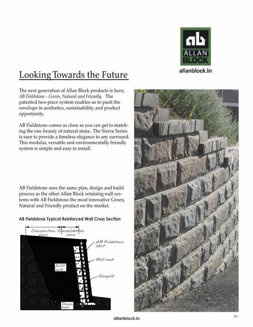
Looking Towards the Future
The next generation of Allan Block products is here;AB Fieldstone - Green, Natural and Friendly. Thepatented two-piece system enables us to push the envelope in aesthetics, sustainability, and product opportunity.
AB Fieldstone comes as close as you can get to match-ing the raw beauty of natural stone. The Sierra Series is sure to provide a timeless elegance to any surround.This modular, versatile and environmentally friendlysystem is simple and easy to install.
AB Fieldstone uses the same plan, design and buildprocess as the other Allan Block retaining wall sys-tems with AB Fieldstone the most innovative Green, Natural and Friendly product on the market.
AB Fieldstone Typical Reinforced Wall Cross Section
allanblock.in 61

©2016 Allan Block Corporation, Bloomington, MN Phone 952-835-5309, Fax 952-835-0013, US Pat. #5,484,236, #6,792,731, #6,322,742 & #6,854,236 Canadian Pat. #2,012,286 ,133,675 Australian Pat. #682,394 & #133,306 Europe Pat. #649,714 & #99,308,421.9 Germany Pat. #69,423,563.6 Japan Pat. #3,142,107 Mexico Pat. #189,846 Taiwan Pat. #NI-72269 AB Fieldstone Pat. #7,775,747 & D624,204S Int’l And Other Patents Pending DOC. #R0621-916
The information and product applications illustrated in this manual have been carefully compiled bythe Allan Block Corporation and, to the best of our knowledge, accurately represent Allan Blockproduct use. Final determination of the suitability of any information or material for the usecontemplated and its manner of use is the sole responsibility of the user. Structural design analysis shallbe performed by a qualified engineer.
Installation ManualAllan Block Retaining Walls
allanblock.in
allanblock.in
allanblock.in
®
PraYoSa Buildmat Pvt. Ltd.2,Sachinam Opp. Sai. Point Honda,
Almeda Road,PanchpakhadiThane (W) 400602
Tel: +91 22 25401275/1065+91 9619183462
Email: [email protected]
Represented in India by PraYoSa - Offering World Class Products to Beautify Indian Landscapes
Best Practices for SRW’sEnsure Zero Wall Failures bylearning the industry’s bestpractices when designingSRW’s.
AB Walls 3DUse our comprehensivedesign software for fullproject submittal’s andshop drawings and 3D BIM type exportable files.Get the most powerfulSRW software available.
Check out the bestmaterials and tools
in the industryfor SRW’s.