Alister Sluiter 586507 - Architecture Design Studio: Air
139
Architecture Design Studio Air Alister Sluiter 586507
description
Â
Transcript of Alister Sluiter 586507 - Architecture Design Studio: Air

Architecture DesignStudio Air
Alister Sluiter 586507


3
ContentsPART A Conceptualisation
ProfileA.1 Design FuturingScene-SensorRed BalloonsTechnology Research - PiezoelectricityA.2 Design ComputationICD/ITKE Research PavilionEndesa PavilionA.3 Compositional vs. GenerativeHyphaeQatar National Convention CentreConclusion and Learning OutcomesReferences
PART B Criteria Design
B.1 Research FieldBiomimicryB.2 Case Study 1.0Iteration MatrixB.3 Case Study 2.0ZA11 PavilionReverse EngineeringB.4 Technique: DevelopmentIteration MatrixB.5 Technique: PrototypeMaterial EfficiencyB.6 Technique: ProposalSite Context and Design IntentsBiofuel from CyanobacteriaExperiential QualitiesB.7 Learning Objectives and OutcomesFeedback and Learning OutcomesReferences
478
10121516182122242628
313235404344465156596063646668717274
PART C Detailed Design
C.1 Design ConceptGenerating ChangeIndustrial WastelandEnvironmental MicrocosmForm from NatureSculpture GardenSolar AnalysisDesign DefinitionC.2 Tectonic ElementsTectonic DevelopmentTectonic ModelC.3 OptimisationExploring OptionsDesign OptimisationEnergy EfficiencyPanelling PatternC.4 DocumentationPlanSection DetailPathsC.5 Final ModelStructural SystemIntimate SpacesLess Intimate SpacesSculpture GardenC.6 Lagi RequirementsLagi RequirementsC.7 Learning Objectives and OutcomesFeedback and Learning OutcomesReferences
777880828486889093949699
100102104106109110112114117118124126128131132135136138

4
My name is Alister Sluiter and I am currently in my 5th semester of the Bachelor of Environments degree, majoring in Architecture. My main interests within architecture lie in architectural history and historic theories of architecture. Since my introduction to digital design in Virtual Environments in first year, however, I have also found an interest in this. In further study, I would like to be able to marry these two fields in an interesting way. In terms of my experience with digital design tools, I have only ever used Rhino in Virtual Environments with the Paneling Tools plug-in. I used Grasshopper once in this subject to create tabs on my unrolled geometries, however the definition was provided for me. An example of my work is shown right. This was my project for the Virtual Environments studio. The brief was to create a paper lantern representative of a dynamic natural process using digital design and fabrication techniques.
So far I have not had that much exposure to digital techniques in architecture. In most of my studios so far we have been asked to use non-digital techniques for design. I’m excited to read, study and create my own digital projects in this studio.
ALISTER SLUITER

5

6

7
Design FuturingA.1

8
SCENE-SENSOR
This project won the 2012 Land Art Generator Initiative competition. Simultaneously it manages to be beautiful as well as creative in its capture of energy and human interactivity.
Essentially, the Scene-Sensor is a bridge connecting too mounds in Fresh Kills Park. This bridge has two components: a wind-mapping screen (fig.1) either side of the bridge; and a series of ramps that offer vantage points across the bridge (fig. 2). In terms of electricity production the scene sensor adopts piezoelectricity in a manner that is not human-reliant in the individual “pixels” that make up the screens. Contortion of the pixels by wind creates electrical current. The ramps also use piezoelectric sensors, although I would presume that this cost would potentially outweigh the benefit. There is, however, more to this project than its electricity-generating capacity; it is also a beautiful addition to the landscape. The screen with its pixels becomes “an index of the intermittent wind flows changing in real time”.1
In my opinion, the best thing about this project is the fact that energy generation was obviously considered from the beginning; it isn’t simply a piece of art which has been covered in solar panels, it is art which performs as a generator in its function. By implementing a form piezoelectricity technology that doesn’t rely on humans, it can also produce energy constantly, both day and night (fig. 3). This is a concept that I will consider in my proposal: ideally my generator should be able to perform constantly without any interaction from humans, although
ideally it would have this interaction.
Design Futuring by Tony Fry proposes the notion that “we only have a future by design”.2 While I’m not suggesting that this proposal answers this problem, as it clearly doesn’t use low embodied energy products or renewable sources, I do think that it is a step in the right direction; it is an example of beautiful, interactive design capable of producing a renewable source of energy.
James Murray, Shota Vashakmadze

9
Fig. 1Scene-Sensor’s wind-mapping screen
Fig. 2Vantage points from within
Fig. 3Scene-Sensor operating at night

10
99 REDBALLOONS99 Red Balloons won 4th place in the Land Art Generator Initiative competition of 2012. It harnesses energy through solar power cells within the “red balloons”. The thing that I like most about this project is its strong metaphorical language. It uses the symbol of the red balloon, borrowed from Nena’s song, to embody a sense of freedom and nostalgia and “perseverance of dreams”.3 A strong overarching theme like this is something I would like to achieve with my own project.
The proposal is an interactive energy-generating experience, which engages its audience both from the site and from a distance. On site, you can wander through the field of red balloons, interacting with their changing opaque to translucent skins which adopt liquid crystal technology, while from a distance, these massive, yet graceful, generators can be seen, giving the on-lookers that sense of nostalgia associated with red balloons that the whole project was attempting to embody.
Looking objectively at the project, I wonder whether the idea of the red balloon was taken too literally, at the expense of some of the project’s purpose. The shape of the balloon doesn’t create the largest surface area exposed to the sun, nor does the arrangement of the balloons, as they would likely cast shadows on each other in their dense arrangement in the centre (fig. 1). This is perhaps a situation where the symbol of the balloon was expressed somewhat too literally, rather than achieving the actual desired outcome of the project - sustainable energy generation.
Scott Rosin, Meaghan Hunter, Danielle Loeb, Emeka Nnadi, Kara McDowell, Jocelyn Chorney, Indrajit Mitra, Narges Ayat, Denis Fleury
11
Fig. 1Perspective showing distribution of Red
Balloons
Fig. 299 Red Balloons, 4th place winner of
LAGI 2012

12
TECHNOLOGY RESEARCH
PIEZOELECTRICITY
Piezoelectricity is energy that is created by mechanical stress.4 There has been research into energy generation from many different sources of mechanical stress, from cars on roads, to buttons on keyboards, however so far it has not been extensively implemented as a viable source of energy.
Some examples of note that have been implemented, however, include PaveGen (fig. 6, 7),5 a pavement generator, and Sustainable Dance Club (fig. 8),6 an energy-generating dance floor used to power clubs such as Club Watt in Rotterdam.
Some reasons why this energy source is not widespread include the large capital outlay that is required to build and install the product, and its relatively low efficiency percentage. One major advantage of this type of energy production is its interactivity; it proposes an active engagement with sustainability. People are able to see and enjoy the results of the energy they produce themselves, which encourages them to produce it in a positive feedback loop.
In relation to the Land Art Generator Intiative, this type of energy provides a huge range of possibilities that could engage a wide community in active participation in sustainability. It could be used to create anything from night time running tracks where the joggers power the lighting that lights their way, to interactive playgrounds for children.
There is, however, a very large risk that human interaction with the site would be overestimated. In
that case the project would fail its primary objective of being an energy generator. It would also cost an outrageous amount of money to produce. Because of this risk, this type of energy generation should not be the primary form on the site.

13
Fig. 6The Pavegen product
Fig. 7An application of Pavegen
Fig. 8Sustainable Dance Club Floor

14

15
Design ComputationA.2

16
ICD/ITKE RESEARCH PAVILION
ICD/ITKE Research Pavilion add reading referenceThis pavilion was developed in a joint effort between the Institute of Computational Design, the Institute of Building Structures and Structural Design, and University of Stuttgart students in 2011.
It is a pavilion made from plywood pieces that were cut using CNC routers so that they would interlock (fig. 9) to create the form (fig. 11).7
The form and structure came from natural sources; the sea urchin. Research into the structure of the sea urchin’s protective layer showed that it was a modular system of polygonal plates.7 This idea was recreated using parametric modelling (a technique demonstrated in the online tutorials created for this subject) to design the form. From there, further computation was implemented to create developable sections that could be cut from 6.5mm thick plywood8 and put together. This incredibly complex form (fig. 10) could be produced simply from readily available and inexpensive materials.
I particularly like this example because of its reference to natural forms. Bio-mimicry is an extremely interesting branch of contemporary architecture and is particularly suitable to being created using computation design, due to its often very complex geometries. “Digital morphogenesis can combine the tectonics of digital material and performative simulation to create naturally ecologic systems.”9 As interesting and beautiful as the form found on the sea urchin is, however, the fact that it was built in Stuttgart, Germany makes it seem
somewhat displaced.
In designing my final project, I will definitely consider sources of inspiration from biology, while considering the location of the site and the form’s relevance to it.
Institute of Computational Design (ICD) and the Institute of Building Structures and Structural Design (ITKE)

17
Fig. 9Interlocking panels
Fig. 10Interior canopy
Fig. 11Exterior of the Research Pavilion

18
ENDESAPAVILION
The familiar principle “form follows function” instantly springs to mind when you look at this project. The design of the pavilion was completely optimised using plugins for Rhino and Grasshopper that would map the position and movement of the sun.10 This optimisation resulted in a building design that maximises the benefit that can be gained from the sun (fig. 12). Its photovoltaic cells are positioned and oriented such that they can perform at their best (fig. 13).
In a time when there are constantly growing concerns in terms of energy and resource consumption and concerted efforts being put into a shift towards renewable energies, it is clear that parametric tools, such as was employed here, may become relied on more and more in a more commercial way.
Optimisation tools like this, however, do have their drawbacks. As is the case in this project, the result is interesting, however debatably ‘beautiful’. To create liveable spaces, I do not believe that we will be able to replace human input altogether. These optimised buildings run the risk of being clinical and not “human” (fig. 14). This is where optimisation in conjunction with human influence needs to be used in order to create results that are comfortable for people to be in.
The future of architecture is this “digital linkage of form generation and performative form finding that is the significance of digital design informed by performance”,11 however it needs to be used wisely in order to create spaces that people enjoy being in.
IaaC: Institute for Advanced Architecture of Catalonia

19
Fig. 12Performative form finding
Fig. 13Maximum solar exposure
Fig. 14A new type of interior experience

20

21
Compositional vs. Generative
A.3

22
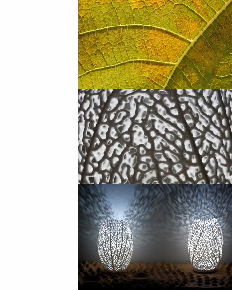
HYPHAENervous System is a generative design firm that explores natural phenomena in what they design. They utilise technology like 3D printing to produce their various collections of jewellery, lighting amongst other things.12
The Hyphae designs are based on the venation observed in leaves (fig. 15).13 Nervous System was able to create an algorithm based on research by Adam Runions of the Algorithmic Botany group at the University of Calgary. This algorithm models how veins are formed, based on movement of auxin, the plant hormone that stimulates growth.13 The algorithm uses points to be “sources of auxin”, other points to be the “roots” of growth, and a base surface. The growth progresses in the average direction of all hormone sources that affect it and branches when there is a source that no longer affects it.13 In this manner, different distributions of sources and different locations of roots produce different venation; generative design which is unique every time (fig. 16, 17).
This sort of digital design isn’t simply a designer creating an object using a computer. The purpose isn’t “to simply digitise existing… processes that are preconceived in the mind of the designer;”14 this is computational design; it is producing unique designs in a generative manner using algorithms.
What I particularly like about this project is that algorithms weren’t arbitrarily created to produce outcomes that looked like the venation observed in leaves. Instead, scientific research was conducted
into how and why venation occurs in the way it does. This research into hormones is what was modelled algorithmically.
Ideally, I would like to be able to create an algorithm that would model something that occurs in nature, however I wouldn’t want to do it superficially, only seeking to recreate a form. This precedent provides a good example to base my thinking off.
Nervous System
23
Fig. 15Leaf venation, from which the design
was based
Fig. 16The resulting pattern of the algorithm
Fig. 17Unique final products

24
QATAR NATIONAL
CONVENTION CENTRE
Generative design has applications other than mimicking natural processes as discussed in relation to the Hyphae project. This project, The Qatar National Convention Centre in Doha, designed by Arata Isozaki and associates in 2011 is an example where biomimicry could be combined with optimisation in terms of material performance in a generative design process.
ESO (evolutionary structural optimisation) is a process that takes basic forms, removes inefficient material and refines them to optimised forms based on the physics of materials and structures.15 The concept was first proposed in the 1990s but only recently has shown up in algorithmic design processes.
This building in Doha was designed to reference the Sidrat al-Muntaha, a holy Islamic tree. The algorithm developed employed ESO with included fitness criteria that mimicked the growth pattern of the native tree. The façade appears to be made of two of these sprawling trees. These trees have, however, been optimised using biomimicry and evolutionary structural optimisation and so theoretically use only the material that is necessary.
While the design of the building took biomimicry into account, the division between architect and engineer is obvious in this design. The building was optimised to use material in a similar manner to the Sidrat-al-Muntaha tree, however the engineers who designed the structure redesigned the internal portion of it, redistributing the material into a different sort of
arrangement.16
Digital fabrication is another astonishing element of this project. Such complex geometry could only be achieved with digital design, and such natural-looking forms from digital design could only be achieved using evolutionary generative. Creating complex geometry is, however, only one of the initial steps in this process. Fabrication is a whole other challenge. In this case, each panel was produced in Malaysia from digital files and shipped to Doha in 12m long shipping containers.16
For my design in this studio, I would be very interested in researching similar evolutionary optimisation algorithms to what was used in this project. To be able to digitally create something that appears so incredibly natural is the ultimate goal.
Arata Isozaki & Associates

25
Fig. 18Natural forms in architecture
Fig. 19Sheer magnitude, yet remarkably
graceful

26
CONCLUSIONANDLEARNING OUTCOMES
Conclusion
The computer is a tool that has effectively reinvented most professions and fields. Architecture is no different. Over the last twenty years, a brand new manner in designing has been created and is still constantly undergoing evolution; parametric design. As Patrik Schumacher said
It is essentially what is defining the now in architecture.
In a time when we are becoming ever more conscious of the role that design has in the future of the world, as outlined by Tony Fry in his call for ethical, intelligent, sustainable design,2 it is clear why new forms of designing such as performative optimised parametric design are being developed and produced.
One of the most amazing things that is coming out of the development of parametricism is biomimicry in generative algorithmic modelling. Combining understanding of the natural world and applying it to design is a fusion that previously could not have been dreamed of, and yet is becoming more and more commonplace.
As far as the debate between human design and
parametric design goes, there is, of course, a valid argument in the fact that parametrics aren’t able to account for every element that makes a building fit for humans. The founding idea of parametricism, however, is that human input is required to create the algorithm, the sequence of rules that produces the outcome. Humans cannot be completely separate from the process.
In my design, tackling generative biomimicry would be what I want to strive to do. For me, generative design is the single most exciting prospect in architecture in the current day.
Learning Outcomes
The last few weeks discussing and putting into practice some ideas of computational design have been incredibly eye opening. It makes you realise just how fast the field of computational design is; that there really is no limit to your creativity.
Generative design is an amazing concept. To think that computers can produce potentially unique objects from the same algorithms is somewhat incredible. In the past I have tried to model natural processes and forms. My understanding then was indeed very stunted. With the skills I hope to develop in this course I’m sure that I would be able to have created more unique, variable forms based on generative principles.
“Parametricism is the great new style after modernism”17

27
Fig. 20Hyphae by Nervous Sytem
Generative biomimicry

References[1] Murray, James and Vashakmadze, Shota (2012). Scene-Sensor, Land Art Generator Initiative, <http://landartgenerator.org/LAGI-2012/AP347043/>.
[2] Fry, Tony (2008). Design Futuring: Sustainability, Ethics and New Practice (Oxford: Berg), p. 3
[3] Rosin, Scott et al (2012). Red Balloons, Land Art Generator Initiative, <http://landartgenerator.org/LAGI-2012/99009900/>.
[4] Encyclopaedia Britannica. Piezoelectricity. <http://www.britannica.com/EBchecked/topic/460053/piezoelectricity>.
[5] Pavegen. <http://www.pavegen.com/>.
[6] Sustainable Dance Club. <http://www.sustainabledanceclub.com/>.
[7] Universität Stuttgart (2011). <http://icd.uni-stuttgart.de/?p=6553>.
[8] Dezeen (2011). ICD/ITKE Research Pavilion at the University of Stuttgart, <http://www.dezeen.com/2011/10/31/icditke-research-pavilion-at-the-university-of-stuttgart/>.
[9] Oxman, Rivka and Robert Oxman, eds (2014). Theories of the Digital in Architecture (London; New York: Routledge), p. 6.
[10] IaaC (2011). Endesa Pavilion, <http://www.iaac.net/archivos/project/pdf/endesa-brocheng.pdf>.
[11] Oxman, Rivka and Robert Oxman, eds (2014). Theories of the Digital in Architecture (London; New York: Routledge), p. 7.
[12] Nervous System. <.n-e-r-v-o-u-s.com>.
[13] Nervous System (2011). Hyphae Lamps – An Infinite Series of Lighting Designs, <http://n-e-r-v-o-u-s.com/blog/?p=1701>.
[14] Peters, Brady. (2013) ‘Computation Works: The Building of Algorithmic Thought’, Architectural Design, 83, 2, p. 10.
[15] Xie, Mike (1997). Evolutionary structural optimization, (London and New York: Springer).
[16] Lane, Thomas (2009). Steel Yourself, <http://www.building.co.uk/steel-yourself-the-qatar-national-convention-centre/3137052.article>.
[17] Schumacher, Patrik (2008). Parametricism as Style – Parametricist Manifesto.
28

29
FiguresFig. 1, 2, 3Scene-Sensor, LAGI 2012 <http://landartgenerator.org/LAGI-2012/AP347043>.
Fig. 4, 5Red Balloons, LAGI 2012 <http://landartgenerator.org/LAGI-2012/99009900/>.
Fig. 6Pavegen. <http://www.pavegen.com/>.
Fig. 7Urban Times, What If Your Footsteps Could Power Your City?, < http://urbantimes.co/2012/10/footsteps-power-city-sustainably-pavegen-paving-tiles-smart/>.
Fig. 8Sustainable Dance Club. <http://www.sustainabled-anceclub.com/>.
Fig. 9, 10, 11 Roland Halbe, <http://icd.uni-stuttgart.de/?p=6553>.
Fig. 12, 13 ,14Archdaily, < http://www.archdaily.com/274900/ende-sa-pavilion-iaac/>.
Fig. 15, 16, 17Nervous System, < http://n-e-r-v-o-u-s.com/blog/?p=1701>.
Fig. 18Inhabitat, < http://inhabitat.com/qatar-national-con-vention-center-goes-for-leed-gold/>.
Fig. 19Archdaily, < http://www.archdaily.com/425521/qa-tar-national-convention-centre-arata-isozaki/>.
Fig. 20Nervous System, < http://n-e-r-v-o-u-s.com/blog/?p=1701>.


3131
Research FieldB.1

3232
BIO-MIMICRY
As a group, we initially decided that we were most interested in biomimicry as a basis for parametric design. It’s a dynamic area of modern parametric design that promises to become even more exciting in the near future. As discussed in Part A, the most exciting area of biometric design is generative parametric design: design that is based on the processes that create natural structures and forms.
As our understanding of nature develops, so too does our understanding of how it can be utilised in new and innovative ways.
Some concerns when developing design from biological sources are often scalability and orientation. For example, structures being unable to support their own weight at large scale compared to similar structures at their smaller, natural scale. This is often due to an inappropriate material selection as materials with similar properties as their natural counterparts aren’t necessarily available yet at the same scale. With orientation, structures evolved to be a certain way to perform best under their natural
conditions. When the structure of something such as honeycomb for example, has its orientation changed, it loses much of its stability from elements such as gravity and instead becomes a flawed system.
There do, however, exist some positive examples of biomimetic design such as the Mercedes Benz Bionic concept car (figure 2). This concept car utilises the form of the boxfish, which, despite having a rather prismatic form, also displays aerodynamic properties. The boxfish form is an appropriate one for a car as it not only provides a roomy interior, it also reduces drag, increasing efficiency of fuels2. It is examples like these which we should be taking advantage of for design futuring. This type of biomimetic design creates efficient, intelligent products; an aspiration that we all should have.
“Biomimetics brings in a whole different set of tools and ideas you wouldn’t other-wise have1”

Fig. 1The boxfish, the inspiration for the
structure and form of the Mercedes Benz Bionic concept car
Fig. 2The Mercedes Benz Bionic concept car
33

34

3535
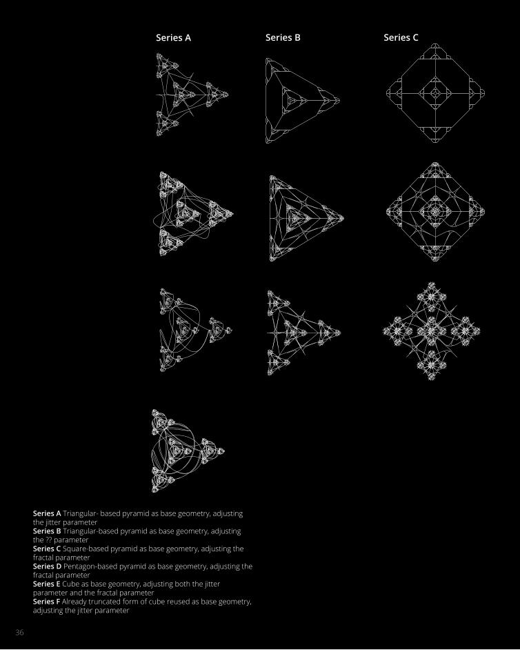
Case Study 1.0B.2Experimenting with The Morning Line Grasshopper definition3
3636
Series A
Series A Triangular- based pyramid as base geometry, adjusting the jitter parameterSeries B Triangular-based pyramid as base geometry, adjusting the ?? parameterSeries C Square-based pyramid as base geometry, adjusting the fractal parameterSeries D Pentagon-based pyramid as base geometry, adjusting the fractal parameterSeries E Cube as base geometry, adjusting both the jitter parameter and the fractal parameterSeries F Already truncated form of cube reused as base geometry, adjusting the jitter parameter
Series B Series C

3737
Fig. 3Matrix of iterations of The Morning LIne
Series D Series E Series F
3838
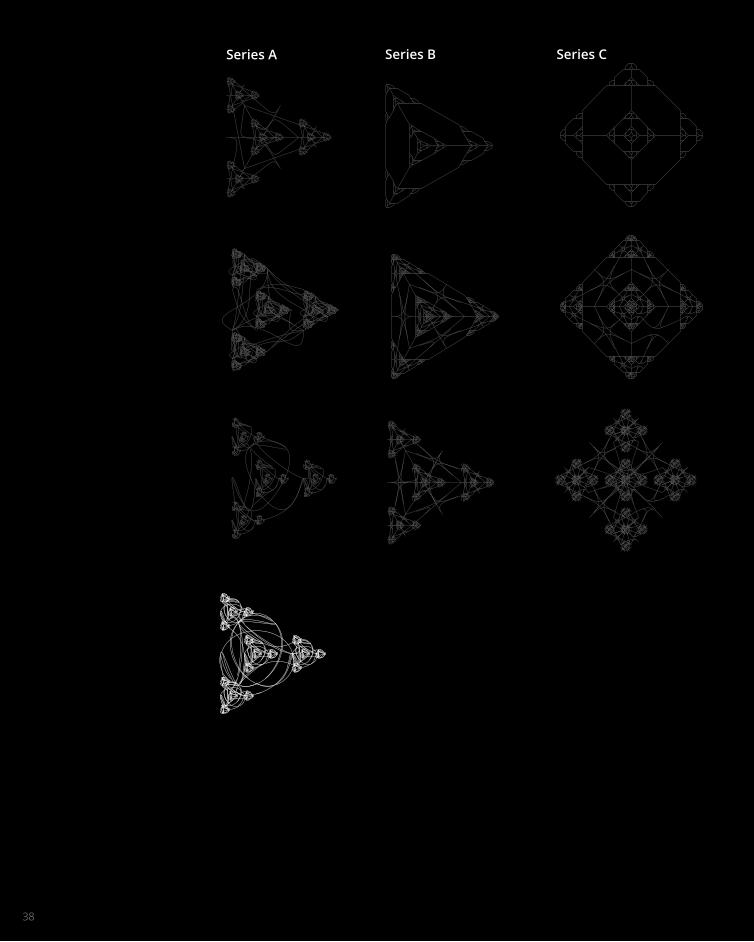
Series A Series B Series C

3939
Fig. 4Matrix of iterations highlighting
successful iterations
Series D Series E Series F

4040
ITERATIONMATRIX
To select the best options from this matrix was difficult as fractal patterns don’t generally have a particularly architectonic form, however the geometries created can be used and considered in other ways than literal translations from definition to architecture.
The selection criteria I followed included:Elegance of formIntricacyPotential use
For these reasons the two I selected have been chosen. The first, based on the triangular-based pyramid but altered using the jitter parameter, created curves of exceeding elegance. These free-flowing curves and an inspiring example of the type of beauty that can be achieved using parametric design.
The second option, based on the pentagonal-based pyramid, was chosen not because of its elegance so to say, but rather for a potential use I could see with it. This included distribution of a different form across the site. In the case of this example, seen in top view, intersections of lines could act as attractor forces, altering density of the distribution of a different definition, or as location points of different forms across the site. This symmetrical form has beauty in its intricacy and fractal patterns like this could be used to create an interestingly distributed design.

4141

42

4343
Case Study 2.0B.3

44
ZA11PAVILION
Unfortunately, I knew my skills in Grasshopper wouldn’t be up to replicating natural processes with generative design so I had to choose a simpler example to reverse engineer that wasn’t generative, but had elements of biomimicry within it. For this reason, I reverse engineered the ZA11 Pavilion by Dimitrie Stefanescu, Patrick Bedarf, and Bogdan Hambasan in 2011.
The ZA11 Pavilion (figure 6) was a student-led project that was part of the ZA11 Speaking Architecture festival in Cluj, Romania. With a small budget and donated materials, the design brief was to create an innovative pavilion that could be a flexible space for uses ranging from a temporary book shop to a performance space. The temporary space was designed to ignite intrigue in passers-by and to draw them into the space for the festival’s various events. This was achieved by creating a spectacular ring subdivided into deep hexagonal prisms that could both define the venue for the events (figure 5) as well as provide glimpses to evoke intrigue and attract people4.
Dimitrie Stefanescu, Patrick Bedarf, and Bogdan Hambasan

Fig. 5ZA11 Pavilion in use during Speaking
Architecture Festival
Fig. 6ZA11 Pavilion
45

46
The process I went about to reverse engineer the pavilion is outlined in figure 7 and detailed more specifically in figures 8 to 13. Figure 7 is a diagram that I was lucky enough to find, outlining the actual parametric process that was undertaken by the designers. This processed outlined is the same one I tried to emulate.
Fig. 7Illustration demonstrating parametric design process
REVERSEENGINEERING

47
Fig. 8Curves as base geometry
Fig. 9Grid from Divide Surface function
Fig. 10Shift and Cull Pattern functions to produce hexagonal grid
Fig. 11Individual hexagonal cells formed using data tree editing and Polyline function
Fig. 12Equal length lines drawn from each vertex using 2-Point Vector function
Fig. 13Developable tubular lofts created using lines

4848

4949
Fig. 14Grasshopper DefinitionHexagonal grid section based on similar definition by Arie-Willem de Jongh5

5050

5151
Technique: Development
B.4

52
Fig. 7Grasshopper DefinitionHexagonal grid section based on similar definition by Arie-Willem de Jongh [1]
3A
4A
4B
5A
5B
5C
6A
1A Straight extrusion1B Straight extrusion, split with curved Brep2A Lines for lofting lengthened by image mapping2B Lines for lofting lengthened by image mapping with inverse image2C Lines for lofting lengthened by image mapping, projecting downwards2D Lines for lofting lengthened by image mapping from curved base surface3A Random cull of straight extrusion3B Random cull of straight extrusion3C Random cull of straight extrusion4A Image mapping lengthening extrusion curve from centroid, capped4B Image mapping (inverse image) lengthening extrusion curve from centroid, capped4C Image mapping lengthening extrusion curve downwards from centroid, capped4D Image mapping (inverse image) lengthening extrusion curve downwards from centroid, capped5A Extrusion to point5B Extrusion to 3 points, each base curve finding nearest point5C Extrusion to 3 points, each base curve finding nearest point with sections deleted6A Extrusion capped with 3 rhombi

53
1A
1B
2A
2B
2C
2D
3B
3C
4C
4D
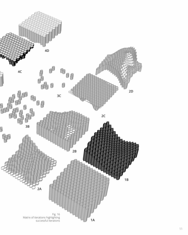
Fig. 15Matrix of iterations of the reverse-
engineered definition

54
Fig. 7Grasshopper DefinitionHexagonal grid section based on similar definition by Arie-Willem de Jongh [1]
3A
4A
4B
5A
5B
5C
6A
1A Straight extrusion1B Straight extrusion, split with curved Brep2A Lines for lofting lengthened by image mapping2B Lines for lofting lengthened by image mapping with inverse image2C Lines for lofting lengthened by image mapping, projecting downwards2D Lines for lofting lengthened by image mapping from curved base surface3A Random cull of straight extrusion3B Random cull of straight extrusion3C Random cull of straight extrusion4A Image mapping lengthening extrusion curve from centroid, capped4B Image mapping (inverse image) lengthening extrusion curve from centroid, capped4C Image mapping lengthening extrusion curve downwards from centroid, capped4D Image mapping (inverse image) lengthening extrusion curve downwards from centroid, capped5A Extrusion to point5B Extrusion to 3 points, each base curve finding nearest point5C Extrusion to 3 points, each base curve finding nearest point with sections deleted6A Extrusion capped with 3 rhombi
55
1A
1B
2A
2B
2C
2D
3B
3C
4C
4D
Fig. 16Matrix of iterations highlighting
successful iterations

56
ITERATIONMATRIX
At this point in time my group and I decided to separate and start our own proposals. This was due to unequal amounts of work being contributed by everyone and a lack of communication between members that seemed wouldn’t be resolved anytime soon. As a result of this, my matrix of iterations is perhaps less extensive than it could be due to time restrictions.
The most successful iterations in my opinion are highlighted on the previous page. The selection criteria I employed included:
Elegance of formDevelopabilityBiomimicking features
Not all of the iterations highlighted fulfilled all of these criteria, however I feel like they are the best four options.
Option 1B was formed from a solid that was trimmed with a Brep. The resultant form has an elegance that is emphasised in the gentle smoothness created by the trim. The form, however, has some limitations. Namely that it cannot be capped with a planar surface as the top edges are all curved in different directions.
Option 4C is a form that was created by getting the centroid of the base grid and projecting it with a varied distance based on image mapping. This extrusion can be capped at both ends because it is planar and as such, very developable.
Option 5A provides opportunity for a more varied patterning, however difficulty of fabrication is increased due to the irregularity of each surface.
Option 6A has a different cap that was created to recreate the back end of honeycomb that allows it to slot into each other. Having this tessellation in 3 dimensions could provide for interesting results once further developed, however it requires that a minimum length extrusion is used, which is limiting.

57

58

5959
Technique: Prototype
B.5

6060
MATERIALEFFICIENCYWith a brief so driven by sustainability it seemed against the brief’s main intentions to create a design that would include a lot of wastage of materials. For this reason one thing I wanted to explore and demonstrate through prototyping was the efficiency that could be achieved with different forms from the same grasshopper definition.
Prototype A (figure 18) is an example of a form where, like in the ZA11 Pavilion, the pattern is extruded to a point and, as a result, the resultant forms are irregular. These irregular forms, therefore, create a lot of wastage once nested for fabrication.
My initial designs were based mostly on extrusion towards a point. Once thinking about and observing, during prototyping the design, the material wastage of the design, I decided to instead to a straight extrusion which would result in more regular shapes that would tessellate and minimise material wastage.
Prototype B (figure 20) demonstrates how by altering the definition a structure which is made up of only tessellating pieces can be produced,
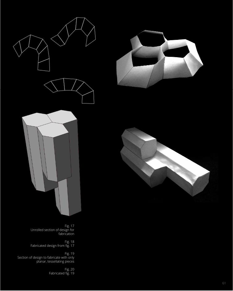
Fig. 17Unrolled section of design for
fabrication
Fig. 18Fabricated design from fig. 17
Fig. 19Section of design to fabricate with only
planar, tessellating pieces
Fig. 20Fabricated fig. 19
61

62

6363
Technique: Proposal
B.6

64
SITE CONTEXT & DESIGN INTENTS
The site of the LAGI Competition is in the centre of an area primarily used for industry. The area which has been allocated has had various uses in the docking industry over time, however currently exists as a flat site where much of the ground is made up of either used building materials as fill or old foundations which are still in the ground6. It exists as a piece of land as far removed from nature as it could be. This can and should be changed with the land art to be placed on it.
Directly across the river from the site is the Little Mermaid, one of the most visited landmarks in Europe and certainly in Denmark. This can be an asset and be utilised to attract people to the site, as people will be able to see it from their vantage point at the Little Mermaid6.
The main design intents I outlined for myself include: making the site an immersive experience, an integration of architecture and sustainability, and a reintroduction of nature into an industrial environment.

Fig. 21Site plan of LAGI site, including
proposed design
THE LITTLEMERMAID
65

66
BIOFUEL FROM
CYANO-BACTERIA
In Part A I chose to explore the energy source of piezoelectricity. While an interesting and interactive energy source, its efficiency, reliability on human interaction, and cost are large factors in choosing not to pursue it in this proposal.
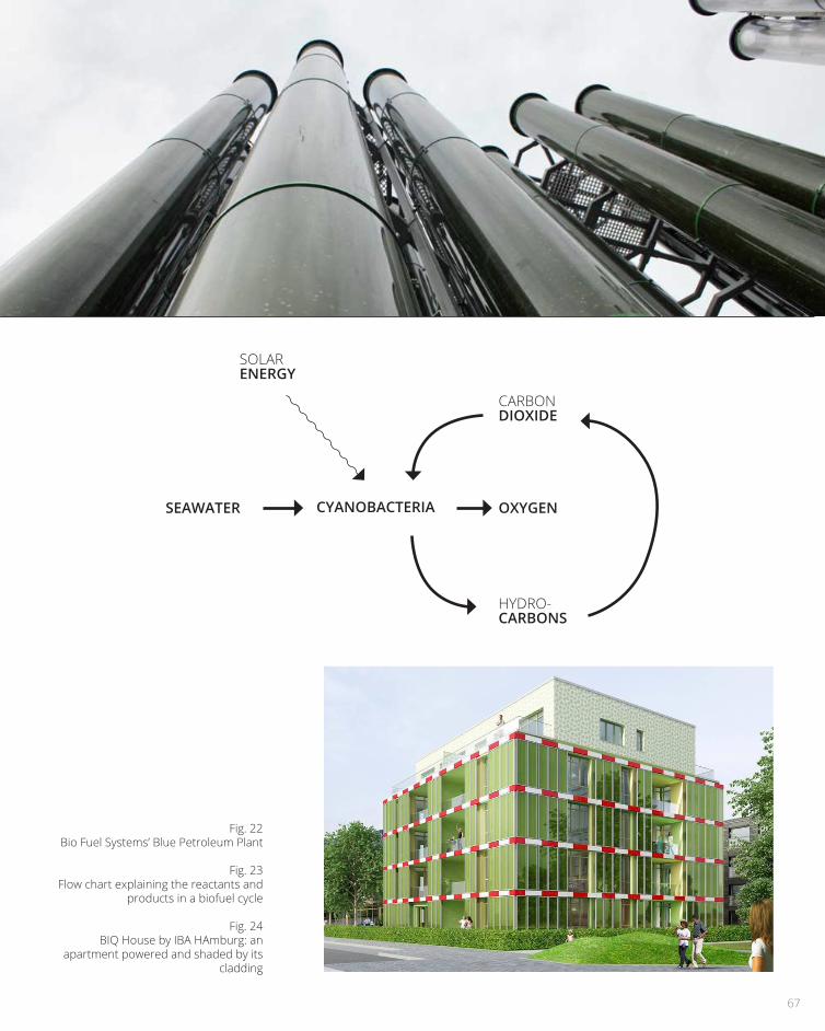
Instead, I decided to focus on biofuel from cyanobacteria, or algae. What convinced me that algae were a good option for the site were the parallels that can be drawn with the past: evolution only occurred because algae produced oxygen in a previously uninhabitable landscape7, so, like then, algae is once again creating an environment fit for humans in what was previously uninhabitable.
Algae convert abundant materials like seawater, carbon dioxide and sunlight into useful products including oxygen and, once treated by transesterification to remove the natural fats, hydrocarbons which can be burnt in existing power plants8. Overall the cycle is carbon neutral – an aim that Copenhagen itself has to achieve by 2025.
Two examples of energy production from algae exist in the Blue Petroleum plant by Bio Fuel Systems9 and the BIQ House by IBA Hamburg10. The fact that companies like Bio Fuel Systems cemented in my mind that biofuel from algae is a viable fuel source.
67
Fig. 22Bio Fuel Systems’ Blue Petroleum Plant
Fig. 23Flow chart explaining the reactants and
products in a biofuel cycle
Fig. 24BIQ House by IBA HAmburg: an
apartment powered and shaded by its cladding
SOLARENERGY
CYANOBACTERIA
CARBONDIOXIDE
HYDRO-CARBONS
OXYGENSEAWATER

6868
EXPERIENTIAL QUALITIES
The form of the structure exists as essentially a canopy made up of various length hexagonal prisms. These prisms need to be made from a transparent material – most likely a type of plastic. The prisms are themselves the bioreactors, similar to the ones seen in Bio Fuel Systems Blue Petroleum plant (figure 23), housing and growing the algae to be harvested and processed periodically.
The justification of the form in its canopy-like shape and the varying length of the prisms can be laid down to the experiential qualities I wanted to achieve with this design.
The first design intent was to create an immersive experience. This was the rationale for the varying length prisms. These lengths were determined by image mapping an image of light shining through branches in a forest. Each prism effectively acts as a pixel, with longer prisms holding more algae, and, thus, appearing darker and letting less light through. This effect casts varying dappled shadows onto the ground underneath the canopy, immersing the visitors in this “green energy” that surrounds them.
The second intent was to integrate architecture and sustainability. Too often, sustainability is an after thought; an add-on to architecture. This is why I wanted to create the form from the energy source and why the prisms make up the protective attributes of what a shelter typically is.
The last intent was to reintroduce of nature into an industrial environment. To achieve this, the canopy
form was chosen. It creates a sort of forest within the industrial context: a canopy not unlike that which you would experience in the forests of Denmark. It brings nature into the unnatural environment and provides visitors with a visual reminder of what the future of Copenhagen relies on.

6969
Fig. 25Dappled light effect created by the
varying depth prisms. An immersive experience
Fig. 26The proposed form of the land art

70

7171
Learning Objectives and Outcomes
B.7

FEEDBACK & LEARNING OUTCOMESThe feedback I received from the interim submissions mostly were to do with my energy system, providing for its optimal conditions and quantifying this. I feel like this would be very difficult to do due to a lack of information available on the productivity of the system and its requirements. Admittedly, the structure would require a large amount of engineering, which would counter a lot of the benefits of using renewable energy. Placing the structure on the ground, however, will also make the design lose most of the qualities I wish to achieve with the proposal as outlined in B.6. For these reasons, from this point forward, I would like to change my proposal, starting with a less limited grasshopper definition and using a technology for which optimisation can occur simply. This technology will most likely be wind or solar.
Learning objectives11:Architecture Design Studio: Air so far has been a subject most unlike the others I have completed so far. It has forced and brought about a deeper understanding of brief “interrogation” and ideation. The use of matrices throughout has assisted me in understanding the way that there are limitless possibilities for design, but also how to create criteria to select the positive outcomes to move forward. The relationship between architecture and air has been difficult for me so far. When designing parametrically, it is easy to become trapped by the fact that in Grasshopper you are designing in space, not in the real world, and, as such, what you’re designing probably won’t stand up, be financially viable, succeed etc. This learning outcome is one I know I
will improve upon for the final presentation. Making a case for proposals is one aspect and learning outcome that I quite enjoy. I like developing my ideas into reasoned arguments to persuade people of their viability. The videos and general exploration I’ve done in Grasshopper has been so useful in developing my personal skills with this incredible plug-in. Coming from being unable to do anything in the program a few weeks ago, I’m quite happy with my ability to problem solve with the software to achieve desired outcomes.
72

73

References1Biomimetics: Design by Nature, Tom Mueller (2008), <http://ngm.nationalgeographic.com/2008/04/biomimetics/tom-mueller-text>.
2Mercedes Benz (2005), <http://www.la.mercedes-benz.com/content/latina/mpc/mpc_latina_website/en/home_mpc/passengercars/home/passengercars_world/innovation_sustainability/future_cars/history/bionic_car.html>.
3Aranda Lasch, The Morning Line, accessed via <https://app.lms.unimelb.edu.au>.
4ArchDaily, ZA11 Pavilion, <http://www.archdaily.com/147948/za11-pavilion-dimitrie-stefanescu-patrick-bedarf-bogdan-hambasan/>.
5Arie-WIllem de Jongh, Complete Hexagon on Surface Script, <http://www.grasshopper3d.com/profiles/blogs/complete-hexagon-on-surface-script-complete-diagrid-on-an-surface>.
6Land Art Generator Initiative, LAGI Design Brief, <http://landartgenerator.org/competition2014.html>.
7ABC, Microscopic algae produce half the oxygen we breathe, <http://www.abc.net.au/radionational/
programs/scienceshow/microscopic-algae-pro-duce-half-the-oxygen-we-breathe/5041338>.
8AlgaeTec, <http://algaetec.com.au/commercialisa-tion-of-algae/>.
9Bio Fuel Systems, <www.biopetroleo.com/english/>.
10IBA Hamburg, <www.iba-hamburg.de>.
11Architecture Design Studio: Air, Course Reader 2014, https://app.lms.unimelb.edu.au.
74

75
FiguresFig. 1,2NetCarShow.com, Mercedes Benz Bionic, <http://www.netcarshow.com/mercedes-benz/2005-bion-ic_concept_car>.
Fig. 3,4Tim Allamby, Iterations of The Morning Line Definition 2014.
Fig. 5David Bondas, < http://www.archdaily.com/147948/za11-pavilion-dimitrie-stefanescu-patrick-bedarf-bog-dan-hambasan/>.
Fig. 6Georgeta Macovei, < http://www.archdaily.com/147948/za11-pavilion-dimitrie-stefanescu-pat-rick-bedarf-bogdan-hambasan/>.
Fig. 7Dimitire Stefanescu, Patrick Bedarf, Bogdan Ham-basan, < Dimitire Stefanescu, Patrick Bedarf, Bogdan Hambasan>.
Fig. 21LAGI Supplementary Materials, < http://landartgener-ator.org/competition2014.html>.
Fig. 23Bio Fuel Systems, <www.biopetroleo.com>.
Fig. 24IBA Hamburg, <www.iba-hamburg.de>.

76

7777
Design ConceptC.1

78
No design is ever perfect. Often they are indeed far from it. Feedback and criticism are necessary and vital aspects of the design process, without which any real progression or development is tremendously difficult.
My proposal from Part B (figure 1), the interim submission, consisted of a canopy of photobioreactors, which grew algae to be processed into hydrocarbons. There were a number of issues with my proposal. These included the fact that my phenomenological reason for raising the photobioreactors off the ground couldn’t outweigh the astronomical effort that would be needed to build the structure to house them. There was also the issue with the distinct lack of optimisation of energy production within my Grasshopper definition and the purely aesthetically driven differential lengthening of my photobioreactors. While creating an interesting light pattern, essentially acting like pixels, it did not involve optimisation of energy production as it really should have.
Up to my interim presentation I had been working from a somewhat limiting definition that I had created earlier in the semester. I was struggling to do anything interesting that involved extrusions of polylines or evolve the definition into something more interesting. This showed in my proposal. To combat this, I decided to start from scratch, creating a new definition that had rationale behind its function.
The main aspect that I kept from interim submission
was the reintroduction of nature into an unnatural site. I disregarded my old definition and the energy source (a source which is difficult to calculate reliable outputs for) that I had incorporated into my design.
Hearing the constructive criticism from the Part B proposal presentations generated significant positive changes in my design.
GENERATING CHANGE

79
Fig. 1Part B Proposal

8080
INDUSTRIAL WASTELANDThe site is situated in Copenhagen dock (figure 2) on reclaimed land that has historically been used for shipbuilding. In its current state, it is a large flat site with few buildings around it, all of which are low, and access via ferry to the southwest. Essentially, it is a blank canvas. In more recent history, the site has been used for landfill and areas of it consist of fill and rubble from demolished buildings.1
The site is about as unnatural as it could possibly be. The site is reclaimed land, the soil is fill and it is surrounded by industry. My design proposes to reintroduce an element of nature into this industrial wasteland. The context will not be ignored in this proposal. I endeavour to create a design that highlights, exaggerates, and celebrates the unnatural-natural tension.

8181
Fig. 2The site context
82
R. Buckminster Fuller put forward ideas in Utopia or Oblivion that described a new type of environment that could be created by humans. Essentially, these environments would be giant glass spheres that would float in the atmosphere, releasing humans of their dependency on earth, its seasons and, indeed, time itself.2 These microcosms would allow a new type of life to develop, more efficient than before. The sealed nature of this type of system was something I wanted to achieve in my design proposal. While reinjecting nature into the site, I also wanted to highlight the distinction between the environments inside and outside of the microcosm and the fact that the inside can exist independent of the outside.
To achieve this independence, I knew that my best option would be to create a glasshouse structure which could sustain life despite its surroundings. Structures like these have existed and functioned for hundreds of years, with great pioneering examples being the Palm Stove at Kew and the Palmenhaus at Schönbrunn in Vienna (Shown in Figures 3 and 4 to be functioning despite extreme weather conditions outside). The excitement that surrounded these examples with their ability to bring tropical plants to places like England and central Europe is an excitement that I want to induce in the visitors to the site in Copenhagen, where nature will be reintroduced into a site previously unthought of possibly being natural.
ENVIRONMENTAL MICROCOSM
“the old concept of man as a cold-area or warm-area dweller or as a fixed, static dweller anywhere, and all the old concepts of seasons, or even of work as related only to daylight hours, will gradually be eradicated from man’s conditioned reflexes”3

83
Fig. 3Schönbrunn Palmenhaus in Winter
Fig. 4Schönbrunn Palmenhaus in Summer

84
While introducing nature into the site in the form of plants, I also wanted the form to be representative of nature. To do this I researched funicular and catenary structures. These structures are formed from flexible materials as they assume a form under gravity.4 This form is stable and can evenly distribute the loads imparted on it by gravity. Robert Hooke proposed these ideas in 1675.5 Architects such as Gaudi and Frei Otto have utilised these theories in their work, with a fantastic of Otto’s work being the Olympiastadion in Munich, Germany (figure 5).
To achieve this effect in Grasshopper, I created a definition that simulated the effect of negative gravity on a mesh, pinned at certain points, thus producing a rational structure that soars above and seems to float while being tethered to the ground as Buckminster’s Cloud Nines would have.
FORM FROM NATURE
“Ut pendet continuum flexile, sic stabit contiguum rigidum inversum”
As hangs the flexible line, so but inverted will stand the rigid arch
Robert Hooke

85
Fig. 5Olympiastadion, Munich
86
As promised earlier when discussing the industrial context, I am endeavouring to highlight, exaggerate, and celebrate the tension between the unnatural and natural with my design. To achieve this I plan to implement negative spaces. These negative interstitial spaces will consist of modern metallic sculpture (figure 6) by local Danish artists. The addition of sculpture gardens will add another dimension to the glasshouse, providing a different sort of space assisting in instigating reflection upon man’s impact on the world.
The sculptural gardens promise to sharply contrast with the glasshouse with a distinction drawn immediately as you exit the enclosed microcosm and enter one of the courtyard sculpture gardens. Sculptural forms will allude to yet distinctly differ from the trees within the glasshouse.
The paths too, will help to signify which sort of space you are in, with organic, curvilinear paths in the glasshouse, and sharp geometric paths on the exterior and in the sculpture gardens.
SCULPTURE GARDEN

87
Fig. 6Arcs in Disorder, Bernar Venet

88
Digital design has opened up a number of opportunities for optimising what we design. Designs such as the one shown right illustrate the potential for this type of application. The design is a portable solar pavilion by Volvo called the Pure Tension Pavilion (figure 7) that is capable of charging an electric car. The designers used solar analysis from Italy to create an array that was optimised for use anywhere in Italy.6
With silicon being such a precious commodity, it is important to optimise solar arrays so as not to waste money and energy producing cells that aren’t in an optimal position. For my proposal, I will analyse solar radiation onto a variety of structures to determine the best configuration of solar cells.
There exist a number of different techniques for incident solar radiation analysis. One such method is made possible with Autodesk’s Ecotect, whereby a mesh, its orientation, and its location is fed into the analyser and the data is returned. This data can then be analysed to determine the best-performing cells and to arrange the solar array. This is the technique I propose to use in my design.
SOLAR ANALYSIS

89
Fig. 7Volvo Pure Tension Pavilion

90
DESIGN DEFINITION
Curves define the base. Every point of discontinuity be-comes a point where the mesh is pinned
From the base curves a basic mesh is formed, which is then made denser
Points along the edges are projected to the ground level. Lines are drawn between these points to define the mul-lions of the glass walls
The inflated mesh is linked to Ecotect using the Geco plugin for Grasshopper, which also retrieves the data and outputs the coloured mesh

91
From the base curves a basic mesh is formed, which is then made denser
The Kangaroo physics simulator is used to apply a negative gravity at each node of the mesh. The mesh deforms and comes to rest, creating a stable, inflated structure
The inflated mesh is linked to Ecotect using the Geco plugin for Grasshopper, which also retrieves the data and outputs the coloured mesh
Values from Ecotect are used to select an optimal array of solar panels
Fig. 8-13Design Definition

92

93
Tectonic ElementsC.2
93

94
TECTONIC DEVELOPMENT
The element I decided to investigate the tectonics of was the repeated system of panels across the base structure. I wanted to create a system that was simple to install and replace pre-fabricated frames of glass or solar cells.
Essentially, circular hollow section steel members form the base structure. Generally, 6 of these members meet at nodes that are hollow spherical steel joints. For each panel, a flange extends inwards from each of the three steel members that make up the base structure of each panel. This flange is used to bolt the panel containing either the glass or solar cell to the base structure. The frame for the glass is made of aluminium.
I decided to employ the flange system described so that both glass panels and solar cells can easily be bolted into it, and so that as new technology develops, the solar cells will be able to be simply replaced for cells that are more efficient. The model (shown on the next page) that accompanies this journal demonstrates the ability the system has to employ both types of panel.
In terms of the solar array, each solar cell will be connected in parallel via conduits in the circular hollow sections. The electricity runs to an AC inverter at ground level which converts the DC energy produced by the solar cells into AC energy which can be fed directly into the Grid.

9595
Glass/solar panel
Glass/solar panel frame
Steel flange for frame to be fixed to
Steel sircular hollow section, joined at hol-
low spherical nodesFig. 14Tectonic development
Fig. 15Exploded Tectonic Detail

96

97
Fig. 16Tectonic Model

98

99
OptimisationC.3
99

100
EXPLORING OPTIONS
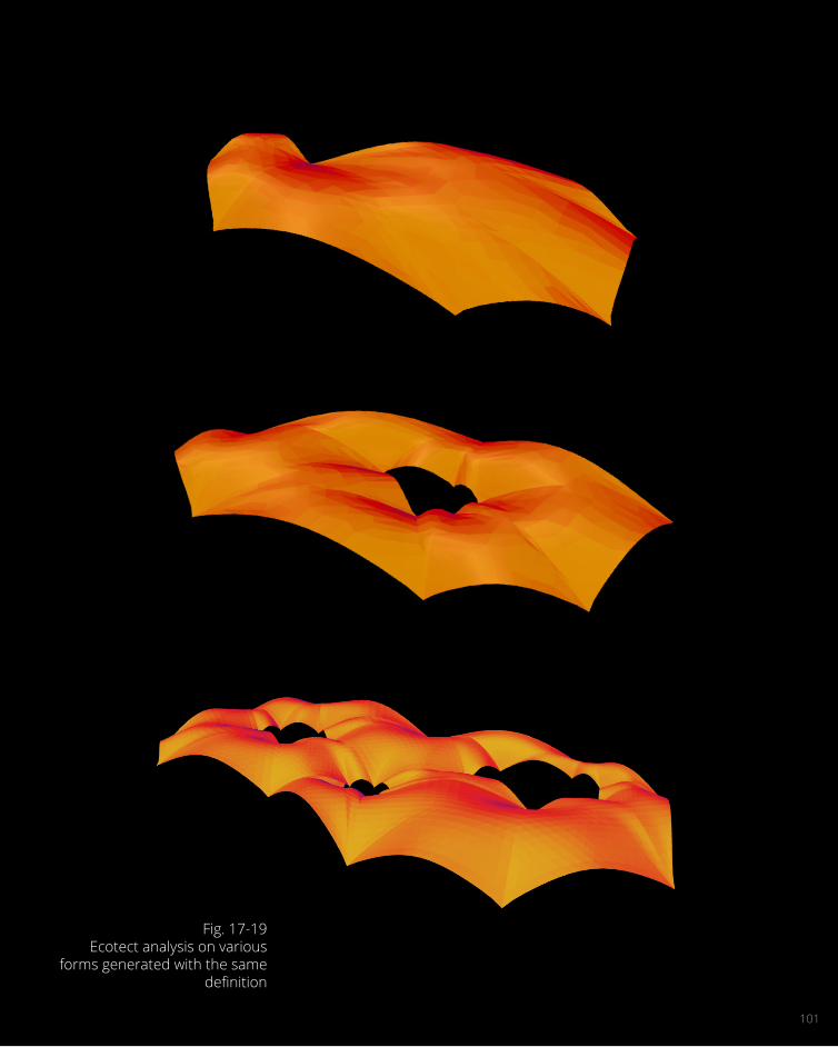
In my design process I created a number of iterations using my Grasshopper definition. These definitions varied by the number of pinned points and the number of internal voids. Three examples created using the same definition are shown in figures 17, 18, and 19.
To choose the most suitable form for my final proposal I decided to setup a criteria based on solar analysis, whereby the amount of solar radiance was analysed used using Autodesk’s Ecotect. What I found while performing these analyses produced remarkably similar results. This can be seen in the similar colour patterns seen right. High amounts of radiance are the yellow-orange sections, while low amounts of radiance are the blue-purple sections. Since most of these forms with their relatively uniform surfaces produced similar results, I decided my criteria would be mostly aesthetically based. My choice of more internal voids comes from the fact that I wanted to include more sculpture gardens within the design.
101
Fig. 17-19Ecotect analysis on various
forms generated with the same definition

102
After I had decided on my final form, I had to optimise my positioning of solar panels to produce the most energy without interfering with the second function of the structure, being a glasshouse.
Ecotect produced results that included the value of incident solar radiation on each panel in W/m2. Using this value and the area of each panel, I was able to calculate the total amount of radiant energy hitting the structure. Using this figure and the energy coefficient of the solar panel I would like to use (20.4%), I was able to calculate the output wattage of the system.
I trialled 4 different design proposals and calculated data for them all. These were:• panelling the best-performing 25% of panels with
solar panels• panelling the best-performing 50% of panels with
solar panels• panelling the best-performing 50% of panels and
then randomly reducing these panels by 33% with solar panels
• panelling all panels of the structure: having the top 25% with solar panels
The first option was efficient, however didn’t produce as much energy as the structure had the potential to. The second option was most efficient, however dramatically overshadowed the interior of the glass house. The third option produced a large amount of energy while not interfering with the function of the glass house. The fourth option produced the most energy, however many of the panels received very
little solar radiation indeed and so would be a waste of energy to produce these cells. The results of this analysis are shown on the next page. I decided to pursue the third option in my design proposal.
DESIGN OPTIMISATION

103
Fig. 20Ecotect analysis on chosen form
direction 1
Fig. 21Ecotect analysis on chosen form
direction 2

104
ENERGY EFFICIENCY
Best-performing 25% panelled with solar panels
Area3915.3 m2
Incident Wattage3.55 MW
Energy Output0.72 MW
Best-performing 50% panelled with solar panels
Area8148.2 m2
Incident Wattage7.11 MW
Energy Output1.45 MW

105
Best-performing 50% panelled with solar panels, then randomly reduced by 33%
Area5424.8 m2
Incident Wattage4.73 MW
Energy Output0.97 MW
100% panelled with solar panels
Area16273.9 m2
Incident Wattage13.02 MW
Energy Output2.66 MW
Fig. 22-25Various solar arrays

106
PANELLING PATTERN

107
Fig. 26The selected solar panel array

108

109
DocumentationC.4
109
110
2
5
1
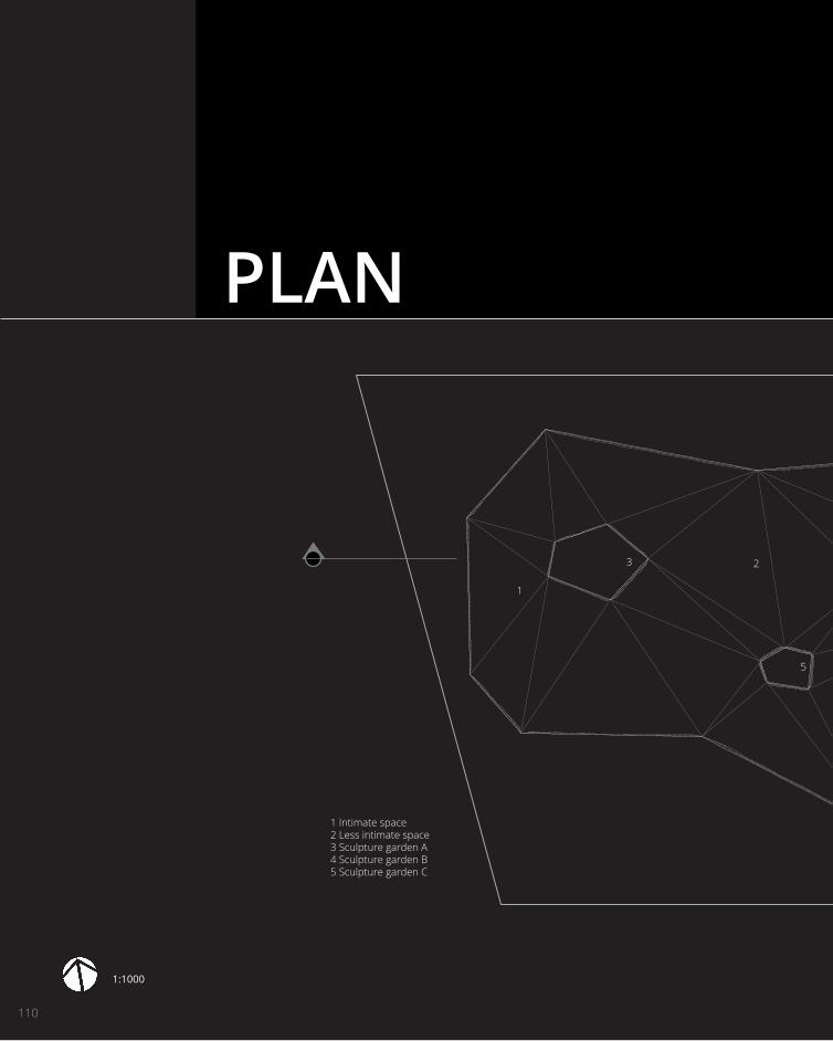
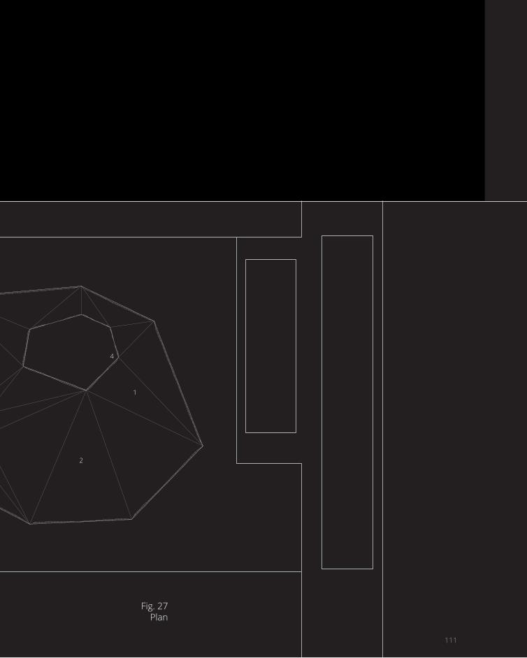
1 Intimate space2 Less intimate space3 Sculpture garden A4 Sculpture garden B5 Sculpture garden C
3
1:1000
PLAN
111111
2
1
4
Fig. 27Plan

112
More intimate interior spaceLower roof with lower growing plants
Sculpture Garden AOutdoor Space without plants
Less intimate spaceTaller roof with larger plant species
SECTION DETAIL

113
Less intimate spaceTaller roof with larger plant species
113
Sculpture Garden BOutdoor space without plants
More intimate inte-rior spaceLower roof with low-er growing plants
Fig. 27Section Detail

114
Paths within the glass house are organic and free-flowing.
Outside and in the sculpture gardens, straight lines and geometry represent the unnatural.
1:1000
PATHS

115115
Fig. 28Path plan

116

117
Final ModelC.5
117


Fig. 29Structural system

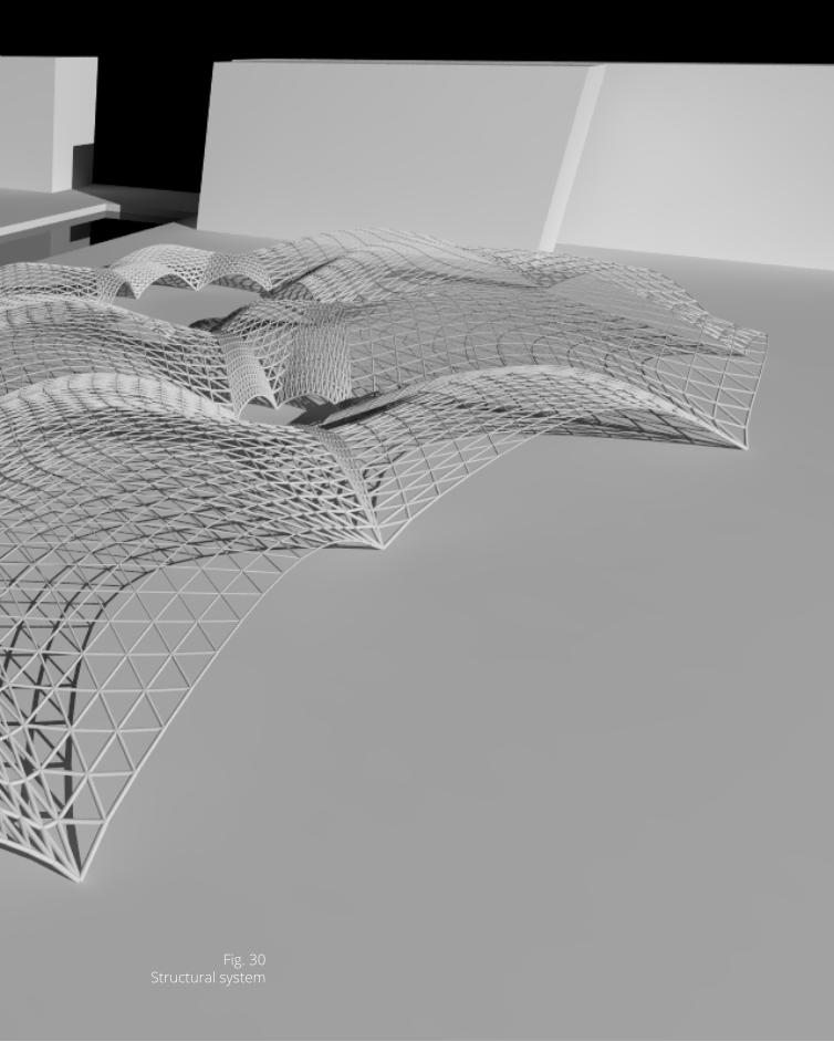
Fig. 30Structural system


Fig. 31Structural system


Fig. 32Intimate spaces with lower roofs


Fig. 33Less intimate spaces with
higher roofs


Fig. 34Sculpture Garden C

130

131
LAGI RequirementsC.6
131

LAGI REQUIREMENTS
An ecosystem is encapsulated within an intricate system of intersecting domes soaring overhead. Formed by nature itself, this form creates an ideal environment to reinject an element of the natural into a site so devoid of nature that its very foundations consist of the rubble of industries past. The glasshouse typology demonstrates the notion of independence from earth’s seasons while emphasising the importance of our solar resource. Both nature and man’s versions of photosynthesis are celebrated in the proposal. Radiant energy is
captured in photovoltaic cells, visible from both the exterior and interior, acting as a constant reminder of our dependence on the sun. Three sculpture garden courtyards interrupt the microcosm, further emphasising man’s separation from nature. Highlighting, exaggerating, and celebrating the divide between the natural and unnatural, the proposal, with its varying experiences, engenders thought about man’s impact on the world, while alluding to the potential for regeneration.

133
Mono-crystalline photovoltaic cells are the energy system to be installed on the structure. They have approximate efficiencies of 20.4%,7 meaning an array capable of producing 0.97MW can be installed onto the structure. The design of the tectonic system ensures that, as technology becomes more efficient, it will be simple to install a new type of solar array.
Primary materials• Steel• Aluminium• Glass• Mono-crystalline photovoltaic cells• Soil• Plants

134

135
Learning Objectives and Outcomes
C.7
135

FEEDBACK & LEARNING OUTCOMESThe feedback I received for my Part C presentation commended my usage of parametric tools, however pointed out the lack of visual evidence of solar analysis. It also indicated the homogeneity of the experience of my site, as well as the lack of detail in my tectonic exploration. I strove to correct all of these things to the best of my ability in the time between receiving this feedback and the submission of this journal.
To provide more visual evidence of solar analysis I decided to change my solar system from a transparent to an opaque cell, giving a visual reminder to the visitors of the site that the structure harnesses solar energy. I also documented my process within ecotect and how I arrived at the final patterning of solar panels in relation to glass panels.
The homogeneity of the experience of my site was addressed in the resolution of the idea of the sculpture garden as well as the section detail. The sculpture garden creates another type of experience of the site, being outdoors, allowing the visitor to see the structure from the outside. The section detail highlights the varied heights of the roofs, indicating the fact that there are more intimate spaces and other less intimate ones.
Tectonic detailing was addressed in the exploded diagram and production of a model to indicate how the structural system can be created to allow for ease of installation, repair, and replacement.
The objectives of the studio focused heavily on obtaining skills in digital design, while also being able to interrogate a brief and produce a detailed
design using these tools. I feel like I have been able to address some of these objectives better than others. Working alone has meant that I have been forced to learn a wide range of skills. I have learnt to work confidently in Grasshopper, analyse structures for optimisation, produce rendered images and compile these in a logical format. While it was difficult to complete all elements of the tasks the groups were assigned by myself, I always tried to the best of my ability.
The design project really challenged my understanding of the design process as it exists in the modern day. Up until now, much of what we had learnt had been focused on the basics which have been the same for many years. This project brought a greater understanding to how modern projects are approached, from the design itself to producing the images that can mean the difference between winning a competition and losing it.
My Grasshopper skills improved out of sight, considering they were non-existent when I started the subject. I am able to create and manipulate objects, data and also the structures that contain them in a controlled manner.
Overall, this subject has given me a much greater understanding of architecture, and in particular digital architecture. Through being introduced to previous examples, I was able to observe the evolution of the techniques themselves. Extrapolating this observance surely insists that there are great futures for the design industry as an entity. It’s an industry I am most certainly excited to witness and be involved in as it progresses.
136

137137

138
References1Land Art Generator Initiative, LAGI Design Brief, <http://landartgenerator.org/competition2014.html>.
2,3R. Buckminster Fuller (1969), from Utopia or Oblivion: The Prospects for Humanity.New York: Overlook Oress, 1969, pp.356-7.
4Quora (2014), <http://www.quora.com/Architecture/What-is-Funicular-geometry-What-is-its-significance-in-Structures-in-Architecture>.
5Philippe Block, Matt DeJong, John Ochsendorf (2006), As Hangs the Flexible Line: Equilibrium of Masonry Arches, Nexus Network Journal, Vol. 8, No. 2.
6Volvo Pure Tension Pavilion (2013), <http://www.dezeen.com/2013/11/14/volvo-pure-tension-pavil-ion-charges-an-electric-car-by-synthesis-design-archi-tecture/>.
7SunPower Mono-crystalline solar panels (2014), <ttp://www.sunpower.com.au/homes/products-ser-vices/solar-panels/>.

139
FiguresFig. 1,8-34Alister Sluiter (2014).
Fig. 2LAGI Supplementary Materials (2014), <http://landart-generator.org/competition2014.html>.
Fig. 3Wolfgang (2008), <http://en.wikipedia.org/wiki/Palmenhaus_Sch%C3%B6nbrunn#mediaviewer/File:Sch%C3%B6nbrunn_20081122_045_Palm_House_Parterre_at_first_snow_sm.jpg>.
Fig. 4Wutzbert (2008), <http://de.wikipedia.org/wiki/Schloss_Sch%C3%B6nbrunn#mediaviewer/Datei:Palm_House_(Sch%C3%B6nbrunn)_seen_from_Palm_House_Parterre_(from_app._N).png>.
Fig. 5Armen Hofen (2012), <https://www.flickr.com/photos/arminhofen/7188288416/>.
Fig. 6Nemo (2013), <http://arte-walk.blogspot.com.au/2013/03/venets-arcs-in-new-orleans.html>.
Fig. 7Autoblog (2013), <http://www.autoblog.com/2013/07/16/volvo-pure-tension-concept-folds-solar-charging-pavilion-into-tr/>.