AlienBot - University of Florida Reports... · AlienBot is an autonomous robot designed and built...
41
AlienBot Final report Juan David Rios ECE graduate student Instructors: A. Antonio Arroyo Eric M. Schwartz TAs: Joshua Weaver Tim Martin University of Florida Department of Electrical and Computer Engineering EEL 5666 Intelligent Machines Design Laboratory
Transcript of AlienBot - University of Florida Reports... · AlienBot is an autonomous robot designed and built...

AlienBot Final report
Juan David Rios
ECE graduate student
Instructors:
A. Antonio Arroyo
Eric M. Schwartz
TAs:
Joshua Weaver
Tim Martin
University of Florida
Department of Electrical and Computer Engineering
EEL 5666
Intelligent Machines Design Laboratory

2
Table of Contents
List of figures ................................................................................................................................................ 3
List of tables .................................................................................................................................................. 4
Abstract ......................................................................................................................................................... 5
1) Executive summary ............................................................................................................................... 6
2) Introduction ........................................................................................................................................... 7
3) Integrated system .................................................................................................................................. 8
4) Mobile platform .................................................................................................................................... 9
5) Actuation ............................................................................................................................................. 10
6) Sensors ................................................................................................................................................ 12
7) Behaviors ............................................................................................................................................ 17
8) Results ................................................................................................................................................. 21
Conclusions ................................................................................................................................................. 22
Future work ................................................................................................................................................. 23
Documentation ............................................................................................................................................ 23
Appendix ..................................................................................................................................................... 24
Shopping places ...................................................................................................................................... 24
Code ........................................................................................................................................................ 24
3
List of figures
Fig. 1. Block diagram of the integrated system ............................................................................................ 8
Fig. 2. Mobile platform ................................................................................................................................. 9
Fig. 3. Metal gearmotor .............................................................................................................................. 10
Fig. 4. Arduino shield MC33926 ................................................................................................................ 11
Fig. 5. Camera of HTC one S ........................................................................................................................ 11
Fig. 6. Laser pointer ..................................................................................................................................... 11
Fig. 7. Pan/tilt mounting ............................................................................................................................. 12
Fig. 8. Futaba servo 3004 ............................................................................................................................ 12
Fig. 9. Sonar sensor ..................................................................................................................................... 12
Fig. 10. Experimental layout to test the ultrasonic modules ....................................................................... 13
Fig. 11. Experimental results: test of the HC-SR04 ultrasonic sensor ........................................................ 14
Fig. 12. QTR-8RC IR Sensor array............................................................................................................. 14
Fig. 13. Experimental layout for the IR array sensor .................................................................................. 15
Fig. 14. Detection of a blue object using OpenCV ..................................................................................... 16
Fig. 15. Detection of a green object using OpenCV ................................................................................... 17
Fig. 16. Physical layout of the ultrasonic modules ..................................................................................... 18
Fig. 17. Physical layout of the IR array sensor ........................................................................................... 19
Fig. 18. Color tracking general idea ............................................................................................................ 19
Fig. 19. Flow diagram of the robot’s behavior ........................................................................................... 20
Fig. 20. AlienBot on the track ..................................................................................................................... 21
Fig. 21. AlienBot......................................................................................................................................... 21

4
List of tables
Table 1. Metal gearmotor dimensions......................................................................................................... 10
Table 2. General specifications ................................................................................................................... 10
Table 3. Futaba servo 3004 specifications .................................................................................................. 12
Table 4. Ultrasonic module specifications .................................................................................................. 13
Table 5. Measurements of the ultrasonic module ....................................................................................... 14
Table 6. Specifications of the QTR-8RC sensor array ................................................................................ 15
Table 7. Measure by the IR sensor over different conditions ..................................................................... 16
Table 8. Actions when the threshold of each sensor is activated ................................................................ 18
Table 9. values read by the IR sensor array ................................................................................................ 19
Table 10. Actions according to the value of errorx and errory ................................................................... 20
5
Abstract
This document presents the final report of the AlienBot project. AlienBot was designed and built
with the guidelines given in the IMDL course at the University of Florida. AlienBot is an
autonomous robot that can follow lines, perform color tracking and avoid obstacles. AlienBot
has two modes of operation: manual and autonomous. These modes can be interchanged from a
Laptop which controls almost every parameter of the robot using serial communication between
the laptop and an arduino board via Bluetooth. The line tracking behavior is achieved using an
array of IR sensors and a PD algorithm to control the movement of the robot over a given line
pattern. Three ultrasonic modules are used in the obstacle avoidance behavior. Finally, for the
color tracking behavior a special system was designed. The special system is composed by a
smartphone’s camera, a pan/tilt system, a laser pointer and the software python/OpenCV. The
main programming languages used in the project were Python and C++.

6
1) Executive summary
AlienBot is an autonomous robot designed and built at the University of Florida. This robot has
several behaviors and an order of precedence for the set of behaviors. These are the main
characteristics of AlienBot:
The robot has three behaviors: line tracking, color tracking and obstacle avoidance.
The precedent of these behaviors is: obstacle avoidance, color tracking, line tracking and
if the robot does not find any of these objects (obstacles, colored objects or lines), it will
move forward.
Once AlienBot finds its target (in the color tracking behavior), it will point over the target
with a laser pointer. This laser is a blue/violet laser with 5mW of power.
It uses two lipo batteries -5500 mAh and 2200 mAh-: one for the power system (metal
gearmotors and servo motors) and another for the sensors and the control. This power is
enough to maintain the robot autonomy for at least 5 hours!
AlienBot uses the H-bridge MC33926 as the main driver. This driver has several built-in
functionalities like for example current sensing, fault detection and direction indicator for
each motor.
AlienBot is powered by two metal gear motors of 100 rpm, 0.3 A of stationary current
and 5 A of stall current. These motors are enough for moving loads of more than 5
pounds but less than 20 pounds.
AlienBot uses an array of eight IR sensors (QTR8RC from pololu) to perform line
tracking, three ultrasonic modules (HCSR-04) with a threshold of 20 cm for obstacle
avoidance and the 8MP camera of an android smartphone (HTC one S) with OpenCV for
color tracking.
AlienBot is connected with a laptop via Bluetooth. It uses the Bluetooth module (JY-
MCU) which has a signal coverage of up to 30 ft and requires an operating voltage of 5
V.
Alienbot uses a pan/tilt system controlled by arduino to track objects of color with the
camera, i.e., the camera will be moved to locate the colored object. Once the object is
located, the control software will turn on the laser and activate an alarm. This pan/tilt
system is powered by two futaba servos 3004.
The computer vision capabilities of AlienBot were achieved using python and OpenCV.
This is a very powerful combination of software given the versatility of python as a
programming language and the amount of built-in functions that OpenCV has.

7
2) Introduction
The goal of this project is to create a robot that can follow lines (with IR sensors), look for
colored objects (aliens from interstellar space) and avoid obstacles. If the robot reaches a dead
end (this is, there is no trajectory or lines to follow), it will move forward avoiding obstacles
(with a configuration of sonar sensors) until finds a colored object or a line (again). If the robot
finds a colored object it will use a laser (controlled by a pan/tilt system) to point over whatever is
ahead and an alarm will be turned on, indicating that the target has been found. In order to
perform this image (color and light intensities) detection, the robot uses the built-in camera of an
android smartphone with OpenCV and python.
The robot has a simple two wheeled platform and an extra support caster wheel in the back. The
priority order of the actions done by the robot is as follows:
1) Avoid obstacles
2) Line tracking
3) Look for colored object
4) Move forward
The development of a robotic system requires the integration of knowledge of several fields:
electronics, mechanics, programming, physics, etc. The design of a good robot is a very complex
task since you will have to develop systems that work fine individually and integrate them.
Together they will have to work fine too, and this is not easy at all. This project requires the
analysis of different possible behaviors, hardware, software, algorithms, designs and concepts.
The main challenge is to choose the best components/ideas/concepts in each of those areas and
accomplish a task successfully. In this paper I will show how I did this. In the first section of the
body I will present the integrated system. This is a summary of all the components chosen for the
robot (primarily hardware components and software). After that, I will show the mobile platform
design in its final stage and the actuation used in the robot. In the subsequent section the sensors
are presented. The development of AlienBot required a lot of sensory systems and they will be
explained in detail in this section. The behaviors section will show each behavior and the general
logic followed by AlienBot to manage these behaviors. Finally, I will give the experimental
layout, the final results and the conclusions of this work.
8
3) Integrated system
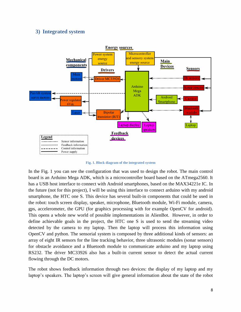
Fig. 1. Block diagram of the integrated system
In the Fig. 1 you can see the configuration that was used to design the robot. The main control
board is an Arduino Mega ADK, which is a microcontroller board based on the ATmega2560. It
has a USB host interface to connect with Android smartphones, based on the MAX34221e IC. In
the future (not for this project), I will be using this interface to connect arduino with my android
smartphone, the HTC one S. This device has several built-in components that could be used in
the robot: touch screen display, speaker, microphone, Bluetooth module, Wi-Fi module, camera,
gps, accelerometer, the GPU (for graphics processing with for example OpenCV for android).
This opens a whole new world of possible implementations in AlienBot. However, in order to
define achievable goals in the project, the HTC one S is used to send the streaming video
detected by the camera to my laptop. Then the laptop will process this information using
OpenCV and python. The sensorial system is composed by three additional kinds of sensors: an
array of eight IR sensors for the line tracking behavior, three ultrasonic modules (sonar sensors)
for obstacle avoidance and a Bluetooth module to communicate arduino and my laptop using
RS232. The driver MC33926 also has a built-in current sensor to detect the actual current
flowing through the DC motors.
The robot shows feedback information through two devices: the display of my laptop and my
laptop’s speakers. The laptop’s screen will give general information about the state of the robot

9
and the speaker will play a sound when the colored object is detected by the color tracking
system. The color tracking system is composed by the android’s camera, a pan/tilt system
powered by two futaba servos and a laser pointer.
The energy supply system is composed of two lipo batteries. The first one will be used to supply
energy to the microcontroller, sensor system and feedback information system; it has a capacity
of 2200 mAh. The second one will give the electrical energy needed to move four motors: two
metal geared motors for the main robot’s mobility and the two futaba servo motors for the
pan/tilt system. The MC33926 arduino shield, which is a H-bridge with several additional
capabilities, will be used as the driver to manage the current required by the motors. A BJT will
control the energy supply of the laser. Finally since the servos work with a range of voltages of
4.8-6 Vdc I used a switched power regulator (5 Vdc or 6 Vdc) to feed them.
4) Mobile platform
AlienBot has a simple platform with two wheels and an extra support caster wheel in the back.
An array of eight IR sensors is used to detect lines on the floor. An additional array of sonar
sensors (three in total) was defined for the obstacle avoidance behavior. A pan/tilt system is used
to control the movement of the laser pointer/camera. This pan/tilt system is in charge of the
mechanical movement of the laser pointer and camera when a colored object is detected by the
camera, the image is processed by OpenCV and a control decision is taken by the pan/tilt system
control algorithm. The main support of the mobile system was designed in wood using wood
sheets of about 4mm of thickness. The Fig. 2 shows a general overview of the mobile platform.
Fig. 2. Mobile platform

10
5) Actuation
The actuation system is done primarily by two DC gear-head motors from pololu controlled by
the MC33926 arduino shield (a H bridge). The change of direction is achieved with differential
steering. Additionally, two servo motors are used in the pan/tilt system to move the camera and
the laser pointer when a colored object is detected. This laser was built by QQ-Tech, has 5mW of
power and projects a blue/violet ray of 405 nm of length wave. In the next list I will describe the
metal gearmotor and the MC33926 arduino shield:
37D mm metal gearmotor:
Fig. 3. Metal gearmotor
The Fig. 3 shows the main dc motor of AlienBot. This 2.22" x 1.45" x 1.45" gearmotor is a
powerful brushed DC motor with 100:1 metal gearbox intended for operation at 12 V. These
units have a 0.61"-long, 6 mm-diameter D-shaped output shaft.
Table 1. Metal gearmotor dimensions
Size: 37D x 57L mm
Weight: 7.1 oz
Shaft diameter: 6 mm
Table 2. General specifications
Gear ratio: 100:1
Free-run speed @ 6V: 50 rpm
Free-run current @ 6V: 250 mA
Stall current @ 6V: 2500 mA
Stall torque @ 6V: 110 oz·in
Free-run speed @ 12V: 100 rpm
Free-run current @ 12V: 300 mA
Stall current @ 12V: 5000 mA
Stall torque @ 12V: 220 oz·in

11
Driver dual MC33926 Motor Driver Shield
Fig. 4. Arduino shield MC33926
This motor driver shield and its corresponding Arduino library make it easy to control two
bidirectional, brushed DC motors with an Arduino or Arduino clone (see Fig. 4). The board
features a pair of Freescale MC33926 motor drivers, which operate from 5 to 28 V and can
deliver a continuous 3 A per channel, and includes current sense circuitry, protection resistors, a
FET for reverse battery protection, and logic gates to reduce the required number of I/O pins. It
ships fully populated with its SMD components, including the two MC33926 ICs, as shown in
the picture to the right; stackable Arduino headers and terminal blocks for connecting motors and
motor power are included but are not soldered in (see the Included Hardware section below).
The pan/tilt system working with the camera and python/OpenCV are the components of my
special system. Here is the description:
Special system: Camera + Laser + pan/tilt system + color recognition with OpenCV
The special system of my robot is composed by the camera of my android cellphone, the HTC
one S, a laser which will be used to point over a colored target, a pan/tilt system to move the
cellphone + laser and the color recognition software programmed with Python and
OpenCV.
The built-in camera of my android smartphone has 8 Megapixels of resolution
with auto focus, LED flash, F2.0 aperture and 28 mm lens. It will be used in the
robot in the color detection. The Fig. 5 shows the rear camera of the HTC one S.
The selected laser is the laser pointer QQ-Tech with 5mW of power, and with a
blue/violet beam of 405 nm of wavelength (see Fig. 6). It requires 3 Vdc.
Fig. 5. Camera of HTC one S
Fig. 6. Laser pointer

12
Finally the pan/tilt system is composed of several parts. The first one is the
pan/tilt framework. I will be using the ServoCity SPT100 Direct pan and tilt support
(see Fig. 7) with Futaba servos. This pan/tilt mounting is perfect for cameras and
sensors up to 10 oz (284 g).
The servo selected for this application is the Futaba S3004 (see Fig. 8). The
specifications are shown below.
Table 3. Futaba servo 3004 specifications
Speed (sec/60 deg) 0.19
Torque (Kg-cm/Oz-in 4.1/57
Size (mm) 41x20x36
Weight (g/oz) 37.2/1.3
I will be working with two servos, one for movement in the pan dimension and another for the
tilt dimension.
6) Sensors
The robot will be using several kinds of sensors to implement different behaviors. The next list
shows each sensor:
Ultrasonic module HC-SR04:
The Fig. 9 shows the sensor used to detect distance with arduino. This is the
ultrasonic module HC-SR04 which is composed of a transmitter (speaker) and a
receiver (microphone). It automatically sends eight sound waves of 40 kHz from
the speaker and detects whether there is a pulse signal back (echo) received in the
microphone. If the signal is back, the time of the high output IO duration is the
time from sending the ultrasonic wave to returning. In this way, we can measure
the distance from the sensor to the obstacle with (eq1).
(eq1)
Fig. 9. Sonar sensor
Fig. 7. Pan/tilt mounting
Fig. 8. Futaba servo 3004

13
Table 4. Ultrasonic module specifications
Working voltage 5 Vdc
Working current 15 mA
Working frequency 40 kHz
Max Range 4000 mm
Min Range 20 mm
Resolution 3 mm
Measuring Angle 15 degree
Trigger Input
Signal
10 uS TTL pulse
Echo Output Signal Input TTL signal and the range in proportion
Dimension 45*20*15 mm
Experimental layout:
I worked with an arduino library designed to control the ultrasonic module. The NewPing
library (you can find the project homepage link in the documentation section) works with
many different ultrasonic sensor modules: SR04, SRF05, SRF06, DYP-ME007 and Parallax
PING.
I am using three ultrasonic sensors of the same kind (HC-SR04) in the robot’s platform. One
of them was put in the front and the other two in the sides with a 45 degrees angle (to right or
left) respect to the frontal sensor, as is shown in Fig. 10.
Fig. 10. Experimental layout to test the ultrasonic modules
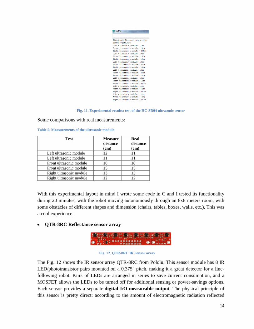
The Fig. 11 shows the results of the test carried out with arduino in the serial monitor reading
obtained in the computer. You can find the program used in the appendix.
14
Fig. 11. Experimental results: test of the HC-SR04 ultrasonic sensor
Some comparisons with real measurements:
Table 5. Measurements of the ultrasonic module
Test Measure
distance
(cm)
Real
distance
(cm)
Left ultrasonic module 12 11
Left ultrasonic module 11 11
Front ultrasonic module 10 10
Front ultrasonic module 15 15
Right ultrasonic module 13 13
Right ultrasonic module 12 12
With this experimental layout in mind I wrote some code in C and I tested its functionality
during 20 minutes, with the robot moving autonomously through an 8x8 meters room, with
some obstacles of different shapes and dimension (chairs, tables, boxes, walls, etc.). This was
a cool experience.
QTR-8RC Reflectance sensor array
Fig. 12. QTR-8RC IR Sensor array
The Fig. 12 shows the IR sensor array QTR-8RC from Pololu. This sensor module has 8 IR
LED/phototransistor pairs mounted on a 0.375" pitch, making it a great detector for a line-
following robot. Pairs of LEDs are arranged in series to save current consumption, and a
MOSFET allows the LEDs to be turned off for additional sensing or power-savings options.
Each sensor provides a separate digital I/O-measurable output. The physical principle of
this sensor is pretty direct: according to the amount of electromagnetic radiation reflected

15
over a surface, the type of material or the surface’s color can be detected. It is known that the
white color reflects all the wave lengths from the visible range of the electromagnetic
spectra. The black color, however, absorbs almost all this radiation. Because of this the
radiation reflected is very low. Therefore, if there is a track created with black lines over a
white surface, the robot could differentiate the track (black colored) and the surface (white
colored). Since this sensor gives 8 digital measurable outputs, we can easily use any of the
digital I/O pins from arduino to read the sensor signal.
Functional description (by Pololu):
The QTR-8RC reflectance sensor array is intended as a line sensor, but it can be used as a
general-purpose proximity or reflectance sensor. Each phototransistor uses a capacitor
discharge circuit that allows a digital I/O line on a microcontroller to take an analog reading
of reflected IR by measuring the discharge time of the capacitor. Shorter capacitor discharge
time is an indication of greater reflection.
Table 6. Specifications of the QTR-8RC sensor array
Operation voltage 3.3-5.0 Vdc
Supply current 100 mA
Output format Digital I/O compatible
Optimal sensing distance 3 mm
Maximum recommended sensing
distance
9.5 mm
Weight without header pins 3.09 g
Dimensions 70x14x15 mm
Experimental layout:
The intended use for this sensor is line tracking. In the Fig. 13 you can see the location of the
sensor array in the platform.
Fig. 13. Experimental layout for the IR array sensor
16
Pololu designed an arduino library for its QRT-8RC array sensor. With this library I started
some preliminary experiments. I tested the QTR-8RC array over different conditions and I
got some interesting measures. The table below shows the measure given by the sensor over
different conditions.
Table 7. Measure by the IR sensor over different conditions
Metric Lights ON Lights OFF Outside
Min Range 2 mm 2 mm Not yet
Max Range 15 mm 15 mm Not yet
The measure when the lights are ON is identical from that when the lights are OFF. In
conclusion, for this sensor array ambient lighting has little effect.
Android’s camera
This camera was described in the special system presentation in the actuation section (section
Experimental layout with the camera:
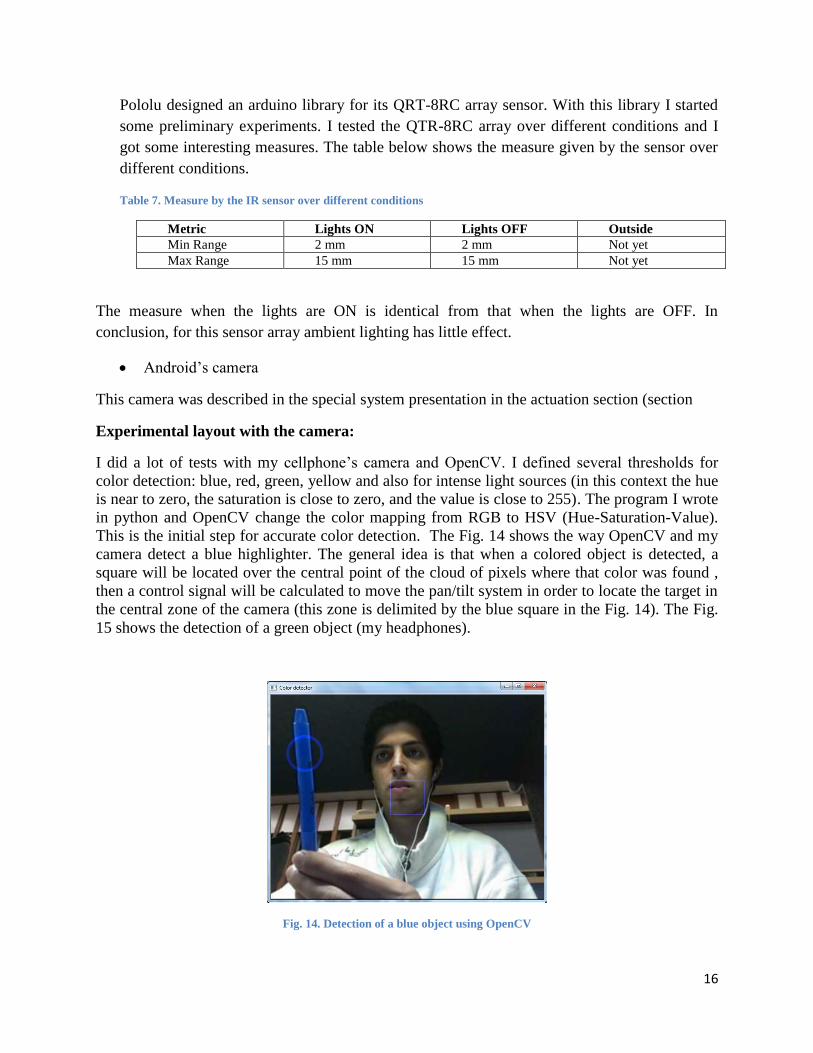
I did a lot of tests with my cellphone’s camera and OpenCV. I defined several thresholds for
color detection: blue, red, green, yellow and also for intense light sources (in this context the hue
is near to zero, the saturation is close to zero, and the value is close to 255). The program I wrote
in python and OpenCV change the color mapping from RGB to HSV (Hue-Saturation-Value).
This is the initial step for accurate color detection. The Fig. 14 shows the way OpenCV and my
camera detect a blue highlighter. The general idea is that when a colored object is detected, a
square will be located over the central point of the cloud of pixels where that color was found ,
then a control signal will be calculated to move the pan/tilt system in order to locate the target in
the central zone of the camera (this zone is delimited by the blue square in the Fig. 14). The Fig.
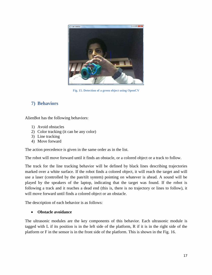
15 shows the detection of a green object (my headphones).
Fig. 14. Detection of a blue object using OpenCV
17
Fig. 15. Detection of a green object using OpenCV
7) Behaviors
AlienBot has the following behaviors:
1) Avoid obstacles
2) Color tracking (it can be any color)
3) Line tracking
4) Move forward
The action precedence is given in the same order as in the list.
The robot will move forward until it finds an obstacle, or a colored object or a track to follow.
The track for the line tracking behavior will be defined by black lines describing trajectories
marked over a white surface. If the robot finds a colored object, it will reach the target and will
use a laser (controlled by the pan/tilt system) pointing on whatever is ahead. A sound will be
played by the speakers of the laptop, indicating that the target was found. If the robot is
following a track and it reaches a dead end (this is, there is no trajectory or lines to follow), it
will move forward until finds a colored object or an obstacle.
The description of each behavior is as follows:
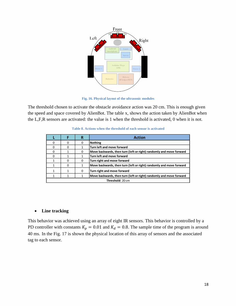
Obstacle avoidance
The ultrasonic modules are the key components of this behavior. Each ultrasonic module is
tagged with L if its position is in the left side of the platform, R if it is in the right side of the
platform or F in the sensor is in the front side of the platform. This is shown in the Fig. 16.
18
Fig. 16. Physical layout of the ultrasonic modules
The threshold chosen to activate the obstacle avoidance action was 20 cm. This is enough given
the speed and space covered by AlienBot. The table x, shows the action taken by AlienBot when
the L,F,R sensors are activated: the value is 1 when the threshold is activated, 0 when it is not.
Table 8. Actions when the threshold of each sensor is activated
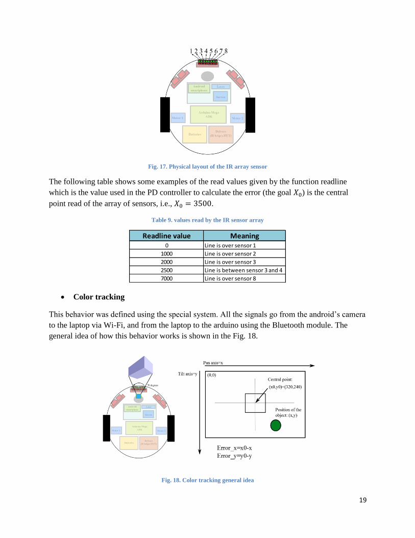
Line tracking
This behavior was achieved using an array of eight IR sensors. This behavior is controlled by a
PD controller with constants and . The sample time of the program is around
40 ms. In the Fig. 17 is shown the physical location of this array of sensors and the associated
tag to each sensor.
L F R Action0 0 0 Nothing
0 0 1 Turn left and move forward
0 1 0 Move backwards, then turn (left or right) randomly and move forward
0 1 1 Turn left and move forward
1 0 0 Turn right and move forward
1 0 1 Move backwards, then turn (left or right) randomly and move forward
1 1 0 Turn right and move forward
1 1 1 Move backwards, then turn (left or right) randomly and move forward
Threshold: 20 cm
19
Fig. 17. Physical layout of the IR array sensor
The following table shows some examples of the read values given by the function readline
which is the value used in the PD controller to calculate the error (the goal ) is the central
point read of the array of sensors, i.e., .
Table 9. values read by the IR sensor array
Color tracking
This behavior was defined using the special system. All the signals go from the android’s camera
to the laptop via Wi-Fi, and from the laptop to the arduino using the Bluetooth module. The
general idea of how this behavior works is shown in the Fig. 18.
Fig. 18. Color tracking general idea
Readline value Meaning0 Line is over sensor 1
1000 Line is over sensor 2
2000 Line is over sensor 3
2500 Line is between sensor 3 and 4
7000 Line is over sensor 8

20
The correction in the position of the camera is given using a P controller. The error in each axis
is calculated as the difference between the reference point (the central point) and the actual
position of the colored object. Then the correction is defined according to the action listed in the
following table:
Table 10. Actions according to the value of errorx and errory
The Fig. 19 shows the logic under which all those behaviors are integrated. The precedence of
the behaviors was included in the flow diagram. The general idea is that each previous behavior
is nested in the next one. The default action is move forward.
Fig. 19. Flow diagram of the robot’s behavior
Condition ActionErrorx<0 Move right (pan servo)
Errorx>0 Move left (pan servo)
Errory<0 Move down (tilt servo)
Errory>0 Move up (tilt servo)
21
8) Results
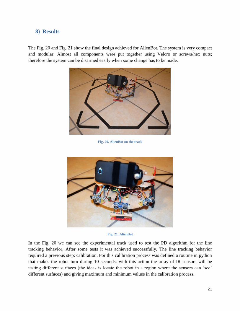
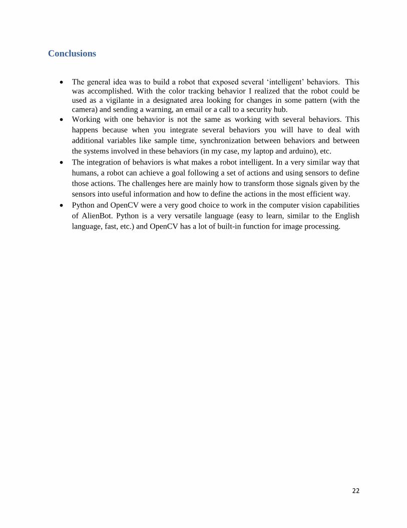
The Fig. 20 and Fig. 21 show the final design achieved for AlienBot. The system is very compact
and modular. Almost all components were put together using Velcro or screws/hex nuts;
therefore the system can be disarmed easily when some change has to be made.
Fig. 20. AlienBot on the track
Fig. 21. AlienBot
In the Fig. 20 we can see the experimental track used to test the PD algorithm for the line
tracking behavior. After some tests it was achieved successfully. The line tracking behavior
required a previous step: calibration. For this calibration process was defined a routine in python
that makes the robot turn during 10 seconds: with this action the array of IR sensors will be
testing different surfaces (the ideas is locate the robot in a region where the sensors can ‘see’
different surfaces) and giving maximum and minimum values in the calibration process.
22
Conclusions
The general idea was to build a robot that exposed several ‘intelligent’ behaviors. This
was accomplished. With the color tracking behavior I realized that the robot could be
used as a vigilante in a designated area looking for changes in some pattern (with the
camera) and sending a warning, an email or a call to a security hub.
Working with one behavior is not the same as working with several behaviors. This
happens because when you integrate several behaviors you will have to deal with
additional variables like sample time, synchronization between behaviors and between
the systems involved in these behaviors (in my case, my laptop and arduino), etc.
The integration of behaviors is what makes a robot intelligent. In a very similar way that
humans, a robot can achieve a goal following a set of actions and using sensors to define
those actions. The challenges here are mainly how to transform those signals given by the
sensors into useful information and how to define the actions in the most efficient way.
Python and OpenCV were a very good choice to work in the computer vision capabilities
of AlienBot. Python is a very versatile language (easy to learn, similar to the English
language, fast, etc.) and OpenCV has a lot of built-in function for image processing.
23
Future work
In the next months I will be improving my robot with the addition of several systems and maybe
more sensors. I will be working with raspberry pi, which is a 512 MB computer with a very
powerful GPU. I would like to use it with OpenCV (and in this way make the robot completely
autonomous). Also, I want to connect the arduino ADK and my android smartphone. I already
did this using a simple program to turn on/off a LED. However, I want take all it has to offer!. I
would like to use encoders in my robot and a PID algorithm for the speed control.
Documentation
[1] Arduino Mega ADK tutorials. Available: http://arduino.cc/en/Tutorial/HomePage
[2] Android Development website. Available: http://developer.android.com/develop/index.html
[3] IMDL webpage. Available: http://mil.ufl.edu/5666/
[4] Society of robots. Available: http://www.societyofrobots.com/
[5] OpenCV webpage. Available: http://opencv.willowgarage.com/wiki/
[6] Computer vision with python. Available: http://programmingcomputervision.com/

24
Appendix
Shopping places
www.radioshack.com - Circuit board, screws, hex nuts, washers
www.lowes.com - Screws, hex nuts, washers, wood, straps and some tools (drill, jigsaw, a
mechanics tool set)
www.sparkfun.com - Switches, tools, LEDs, ribbon cable
www.hobbypartz.com - Batteries- free shipping for +100$ orders
www.robotshop.com - Servos, pan/tilt framework
www.adafruit.com - Arduino Mega ADK
www.amazon.com Ultrasonic modules, Bluetooth module, tools, laser
www.pololu.com - Metal gear motors, wheels, bracket, mounting hub, motor driver, IR sensor
array
Code
Arduino AlienBot’s code for the autonomous-manual mode.
/* This is the source code of the autonomous behavior of AlienBot. A project at the University of Florida. IMDL 2012*/
//Motor driver library
#include "DualMC33926MotorShield.h"
//Library of the IR sensor array
#include <QTRSensors.h>
//Servo library
#include <Servo.h>
//Ultrasonic library for the ultrasonic module HC-SR04
#include "NewPing.h"
/*Declare Constants and Pin Numbers*/
25
#define ECHO_PINl 14
#define TRIG_PINl 15
#define ECHO_PINf 16
#define TRIG_PINf 17
#define ECHO_PINr 31
#define TRIG_PINr 33
#define NUM_SENSORS 8 // number of sensors used
#define TIMEOUT 2500 // waits for 2500 us for sensor outputs to go low
#define EMITTER_PIN 22 // emitter is controlled by digital pin 22
/*Declare objects*/
Servo myservop,myservot; // create servo object to control a servo
NewPing sonar_l(TRIG_PINl, ECHO_PINl,200);
NewPing sonar_f(TRIG_PINf, ECHO_PINf,200);
NewPing sonar_r(TRIG_PINr, ECHO_PINr,200);
QTRSensorsRC qtrrc((unsigned char[]) {24,26,28,30,32,34,36,38},
NUM_SENSORS, TIMEOUT, EMITTER_PIN); // sensors 0 through 7 are connected to digital pins 24 through 38 (even
numbers), respectively
DualMC33926MotorShield md;
/*Declare Variables*/
//Define the pin for turn the laser off/on/
int laser=5;
//Variable to indicate if a colored object or an intense light source has been found
int laser_ind=0;
//Line tracking values
26
unsigned int sensorValues[NUM_SENSORS];
//To detect when all the sensors are over the black line
int bias=800;
//Error for PD control in line tracking
int error;
int last_error=0;
float speed_pd;
//Kp and kd values of the controller
float kp=0.01; //kp=0.025 -fkp=0.02 st=250ms -spfkp=0.01 st=50ms
float kd=0.8; //kd=0.5 -fkd=0.4 -spfkp=0.8 a m1=150 lim=200
int posp = 85; // variable to store the pan servo position
int post= 40; // variable to store the tilt servo position
//Default distances at the beginning
int l=400;
int f=400;
int r=400;
//Set speed of motors m1 and m2
int m1=150;
int m2=150;
int m1v=0;
int m2v=0;
//Threshold distance of activation of the ultrasonic sensors (in cm)
int gap=20;
//Random choice of turn direction
int randgy;
//Random time for turning

27
int randtime; //425ms=45 degrees - 850ms=90 degrees - 1700=180 degrees
//Automatic mode (false by default)
int aut=0;
//Direction in manual control mode
int mov=0;
//Variable to keep track of the returning time of the echo (ultrasonic modules)
unsigned int uS;
//Variable for the detection of lines
unsigned int position;
//Indicates if an object was found
int object=0;
//Function for the calibration of the IR sensor array
void IRcalibration()
{
delay(500);
int i;
for (i = 0; i < 200; i++) // make the calibration take about 10 seconds
{
qtrrc.calibrate(); // reads all sensors 10 times at 2500 us per read (i.e. ~25 ms per call)
}
/*
// print the calibration minimum values measured when emitters were on
for (i = 0; i < NUM_SENSORS; i++)
{

28
Serial1.print(qtrrc.calibratedMinimumOn[i]);
Serial1.print(' ');
}
Serial1.println();
// print the calibration maximum values measured when emitters were on
for (i = 0; i < NUM_SENSORS; i++)
{
Serial1.print(qtrrc.calibratedMaximumOn[i]);
Serial1.print(' ');
}
Serial1.println();
*/
}
//Stop the motors if a fault is found
void stopIfFault()
{
if (md.getFault())
{
/*Serial1.println("fault");*/
while(1);
}
}
//Moving forward
void movefwd(int m1,int m2)
{
md.setSpeeds(m1,m2);
stopIfFault();
/*
Serial1.print("M1 current: ");

29
Serial1.println(md.getM1CurrentMilliamps());
Serial1.print("M2 current: ");
Serial1.println(md.getM2CurrentMilliamps());*/
}
//Moving backwards
void movebwd(int m1,int m2)
{
md.setSpeeds(-m1,-m2);
stopIfFault();
/*
Serial1.print("M1 current: ");
Serial1.println(md.getM1CurrentMilliamps());
Serial1.print("M2 current: ");
Serial1.println(md.getM2CurrentMilliamps());*/
}
//Turn right
void turnr(int m1,int m2, int ran)
{
md.setSpeeds(m1,-m2);
stopIfFault();
/*
Serial1.print("M1 current: ");
Serial1.println(md.getM1CurrentMilliamps());
Serial1.print("M2 current: ");
Serial1.println(md.getM2CurrentMilliamps());*/
delay(ran);
}
30
//Turn left
void turnl(int m1,int m2,int ran)
{
md.setSpeeds(-m1,m2);
stopIfFault();
/*
Serial1.print("M1 current: ");
Serial1.println(md.getM1CurrentMilliamps());
Serial1.print("M2 current: ");
Serial1.println(md.getM2CurrentMilliamps());*/
delay(ran);
}
void collision_avoidance(){
if (l<=gap and r>gap){
//Serial1.println("Turn right activated!");
turnr(m1,m2,random(400,1700));
movefwd(m1,m2);
//Serial1.println("Move forward activated!");
}
else if (l>gap and r<=gap){
//Serial1.println("Turn left activated!");
turnl(m1,m2,random(400,1700));
movefwd(m1,m2);
//Serial1.println("Move forward activated!");
}
else if ((l<=gap and r<=gap) or f<=gap){
//Serial1.println("Move backwards activated!");
movebwd(m1,m2);
delay(1000);
randgy=random(-5,5);
31
if (randgy>0){
//Serial1.println("Turn left activated!");
turnl(m1,m2,random(400,1700));
movefwd(m1,m2);}
//Serial1.println("Move forward activated!");}
else{
//Serial1.println("Turn right activated!");
turnr(m1,m2,random(400,1700));
movefwd(m1,m2);}
//Serial1.println("Move forward activated!");}
}
}
void line_tracking()
{
if (sensorValues[0]>bias and sensorValues[1]>bias and sensorValues[2]>bias and sensorValues[3]>bias and
sensorValues[4]>bias and sensorValues[5]>bias and sensorValues[6]>bias and sensorValues[7]>bias)
{turnl(m1,m2,1200); }
error=position-3500;
speed_pd=kp*error+kd*(error - last_error);
m1v=m1+speed_pd;
m2v=m2-speed_pd;
if (m1v<0)
{m1v=0;}
if (m1v>200)
{m1v=200;}
if (m2v<0)
{m2v=0;}

32
if (m2v>200)
{m2v=200;}
if (error<-1000)
{turnr(m1v,m2v,0);}
else if (error>1000)
{turnl(m1v,m2v,0);
}
else
{movefwd(m1v,m2v);}
/*
// print the sensor values as numbers from 0 to 9, where 0 means maximum reflectance and
// 9 means minimum reflectance, followed by the line position
unsigned char i;
for (i = 0; i < NUM_SENSORS; i++)
{
Serial1.print(sensorValues[i] * 10 / 1001);
Serial1.print(' ');
}
Serial1.print(" ");
Serial1.println(position);
*/
delay(50);}
void setup() /*SETUP: RUNS ONCE*/
{
Serial1.begin(9600);
md.init();
//Serial1.println("AlienBot control system via Serial1 communication");
//Serial1.println("[email protected] - IMDL project");

33
myservop.attach(3); // attaches the servo on pin 2 and 3 to the servo object
myservot.attach(2);
myservop.write(posp);
myservot.write(post);
pinMode(laser,OUTPUT);
}//--(end setup )---
void loop() /*LOOP: RUNS CONSTANTLY*/
{
while (Serial1.available() > 0) {
aut=Serial1.parseInt();
mov=Serial1.parseInt();
int m=Serial1.parseInt();
posp=Serial1.parseInt();
post=Serial1.parseInt();
int d=Serial1.parseInt();
int e=Serial1.parseInt();
laser_ind=Serial1.parseInt();
object=Serial1.parseInt();
if (Serial1.read() == '\n') {
if (laser_ind==1){
digitalWrite(laser,HIGH);}
else{
digitalWrite(laser,LOW);}
posp=constrain(posp,0,180);
post=constrain(post,30,130);
myservop.write(posp); //Set the tilt servo position to the value of the second command byte received on the Serial1 port
myservot.write(post); //Set the pan servo position to the value of the second command byte received from the Serial1 port.
m1=m;
34
m2=m;
kp=d/100;
kd=e/100;
}
}
//Manual mode of operation of the AlienBot
if (aut==0){
myservop.write(posp); //Set the tilt servo position to the value of the second command byte received on the Serial1 port
myservot.write(post); //Set the pan servo position to the value of the second command byte received from the Serial1 port.
if (mov==0){
md.setSpeeds(0,0);}
else if (mov==1){
movefwd(m1,m2);}
else if (mov==2) {
movebwd(m1,m2);}
else if (mov==3) {
turnr(m1,m2,0);}
else if (mov==4) {
turnl(m1,m2,0);}
}
//Automatic mode of operation of the AlienBot
else if(aut==1){
delay(30); // Wait 50ms between pings (about 20 pings/sec). 29ms should be the shortest delay between pings.
//Frontal sonar
uS = sonar_f.ping(); // Send ping, get ping time in microseconds (uS).

35
f=sonar_f.convert_cm(uS);
if (f<1) {f=400;}
/*Serial1.print("Front sonar: ");
Serial1.print(f); // Convert ping time to distance and print result (0 = outside set distance range, no ping echo)
Serial1.print(" cm");*/
//Left sonar
uS = sonar_l.ping(); // Send ping, get ping time in microseconds (uS).
l=sonar_l.convert_cm(uS);
if (l<1) {l=400;}
/*Serial1.print("\tLeft sonar: ");
Serial1.print(l); // Convert ping time to distance and print result (0 = outside set distance range, no ping echo)
Serial1.print(" cm");*/
//Right sonar
uS = sonar_r.ping(); // Send ping, get ping time in microseconds (uS).
r=sonar_r.convert_cm(uS);
if (r<1) {r=400;}
/*
Serial1.print("\tRight sonar: ");
Serial1.print(r); // Convert ping time to distance and print result (0 = outside set distance range, no ping echo)
Serial1.println(" cm");*/
// qtra.read(sensorValues);
position = qtrrc.readLine(sensorValues);
if (l<=gap or f<=gap or r<=gap){
collision_avoidance();
}
else if (object==1)

36
{md.setSpeeds(0,0);
}
else if (position>0 and position<7000){
line_tracking();
}
else
{movefwd(m1,m2);
}
Serial1.write('1');
}
else if (aut==2){
turnr(m1,m2,0);
IRcalibration();
md.setSpeeds(0,0);
aut=0;
mov=0;
}
//end main loop
}
Python AlienBot’s code for the autonomus-manual mode
# -*- coding: utf-8 -*-
"""
Created on Tue Oct 23 01:33:23 2012
@author: JuanD
"""
#About releasing memory in OpenCV:
http://opencv.willowgarage.com/documentation/python/dynamic_structures.html
#Memory management in OpenCV: http://www.aishack.in/2010/01/opencv-memory-management/
import mp3play

37
filename1 = r'mg3.mp3'
filename2 = r'mg3.mp3'
filename3 = r'mg.mp3'
from cv2 import cv
import serial
import msvcrt as kb
ard=serial.Serial(3)
color_window = "AlienBot project"
class ColorTracker:
def __init__(self):
cv.NamedWindow( color_window, 1 )
self.capture = cv.CaptureFromCAM(1)
def run(self):
movi={0:'Manual',1:'Autonomous',2:'Calibration'}
movement={0:'stop', 1:'up',2:'down',3:'right', 4:'left'}
esc=27 #Exit of the program using Escape
tab=9 #For changing modes of operation
m=150 #Actual speed of the robot
#PD constanst of the line tracking behavior of the robot
kp=1
kd=80
#Robot movement controls
enter=13 # v=118 change motor's speed
st=45 #For changing steps -pan-tilt system
up=72 #up arrow- tilt up
rup=119 #w -robot forward
down=80 #down arrow- tilt down
rdown=115 #s - robot backwards
left=75 #left arrow - pan left
rleft=97 #a - robot turn left
right=77 #RIght arrow- pan right
rright=100 #d- robot turn right
stop=101 #e - The robot stops
mod=107 #k - For change values of the PD controls - style #1,#2
move=0
col=99 #c - For selecting color in the color tracking behavior (green is the default color)
colorc='g'
color={'g':((72,100, 40), (90, 255, 255)),'b':((101,200,50),(110,255,100)),
'y':((28,210,60),(35,255,130)),'hi':((0,0,240),(5,5,255))}
if colorc=='g':
mp3 = mp3play.load(filename1)
elif colorc=='b':
mp3 = mp3play.load(filename2)
else:
mp3 = mp3play.load(filename3)
x0=320
y0=240
x=x0
y=y0

38
errorx=0
errory=0
posp=85
post=40
framelimit=45;
aut=0
step=1
object_finder=0
play=0
cont=500
while True:
laser=0
object_finder=0
if kb.kbhit():
c=kb.getch()
if ord(c)==tab:
if aut in (1,2):
move=0
aut=input('Enter operation mode: ')
if aut==1:
step=1
posp=85
post=40
elif ord(c)==enter:
m=input('Enter new speed (from 0 to 400): ')
if m<0:
print 'Speed limited to 0 (only values between 0 and 400 are allowed)'
m=0
if m>400:
print 'Speed limited to 400 (only values between 0 and 400 are allowed)'
m=400
elif ord(c)==up:
post+=step
if (post>130):
post=130
elif ord(c)==down:
post-=step
if (post<30):
post=30
elif ord(c)==right:
posp-=step
if (posp<0):
posp=0
elif ord(c)==left:
posp+=step
if (posp>180):
posp=180
elif ord(c)==stop:
move=0
elif ord(c)==rup:
move=1
elif ord(c)==rdown:
move=2
elif ord(c)==rright:
move=3
39
elif ord(c)==rleft:
move=4
elif ord(c)==col:
colorc=raw_input('Enter new color(actual feature='+colorc+') options -gby-hi-: ')
elif ord(c)==mod:
kp,kd=input('Enter values for kp and kd *100: ')
elif ord(c)==st:
step=input('Enter new step: ')
elif ord(c)==esc:
break
ard.write(str(aut)+','+str(move)+','+str(m)+','+str(posp)+','+str(post)+','+str(kp)+','+str(kd)+','+str(laser)+','+str(object_fi
nder)+'\n')
if aut==2:
aut=0
move=0
print 'code: ',ord(c), '--robot mode: ',movi[aut],'--movement: ',movement[move], '--speed: ',m, '--pan angle:
',posp, '--tilt angle: ',post,'--kp:',kp,'--kd',kd,'--Color: ',colorc,'--Object detected? ',object_finder
img = cv.QueryFrame( self.capture )
if (aut==1):
#blur the source image to reduce color noise
cv.Smooth(img, img, cv.CV_BLUR, 3);
#convert the image to hsv(Hue, Saturation, Value) so its
#easier to determine the color to track(hue)
hsv_img = cv.CreateImage(cv.GetSize(img), 8, 3)
cv.CvtColor(img, hsv_img, cv.CV_BGR2HSV)
#This is a filter will allow us to adjust the range changing the first value in
#both turples, which is the hue range(50,55). OpenCV uses 0-180 as
#a hue range for the HSV color model
#Object
thresholded_img = cv.CreateImage(cv.GetSize(hsv_img), 8, 1)
cv.InRangeS(hsv_img, color[colorc][0], color[colorc][1], thresholded_img)
del hsv_img
#determine the objects moments and check that the area is large
#enough to be our object
moments = cv.Moments(cv.GetMat(thresholded_img,1), 0)
area = cv.GetCentralMoment(moments, 0, 0)
#there can be noise in the video so ignore objects with small areas
if(area > 100000 and area<100000000):
cont=0
object_finder=1
laser=0
#determine the x and y coordinates of the center of the object
#we are tracking by dividing the 1, 0 and 0, 1 moments by the area
x = cv.GetSpatialMoment(moments, 1, 0)/area
y = cv.GetSpatialMoment(moments, 0, 1)/area
print 'errorx=',x-x0,' errory=', y-y0
#print 'x: ' + str(x) + ' y: ' + str(y) + ' area: ' + str(area)
#create an overlay to mark the center of the tracked object
overlay = cv.CreateImage(cv.GetSize(img), 8, 3)
cv.Rectangle(overlay,(x0-40,y0-40),(x0+40,y0+40),(200, 10, 0))
40
cv.Circle(overlay, (int(x), int(y)), 40, (100, 10, 0), 5)
cv.Add(img, overlay,img)
del overlay
print 'Position x: ',x, ' Position y: ',y
#print ard.readlines()
#add the thresholded image back to the img so we can see what was
#left after it was applied
#cv.Merge(thresholded_img, None, None, None, img)
del thresholded_img
errorx=x-x0
errory=y-y0
if (errorx>framelimit):
posp-=step
if (posp<0):
posp=0
elif (errorx<-framelimit):
posp+=step
if (posp>180):
posp=180
if (errory>framelimit):
post-=step
if (post<30):
post=30
elif (errory<-framelimit):
post+=step;
if (post>130):
post=130
if abs(errorx)<framelimit and abs(errory)<framelimit:
laser=1
if laser==1 and play==0:
mp3.play()
play=1
print 'code: ',ord(c), '--robot mode: ',movi[aut],'--movement: ',movement[move], '--speed: ',m, '--pan angle:
',posp, '--tilt angle: ',post,'--kp:',kp,'--kd',kd,'--Color: ',colorc,'--Object detected? ',object_finder
else:
if cont<16:
cont+=1
if cont==16:
posp=85
post=40
last_data=ard.read()
#print last_data
if laser==0 and play==1:
mp3.stop()
play=0
if last_data=='1':
ard.write(str(aut)+','+str(move)+','+str(m)+','+str(posp)+','+str(post)+','+str(kp)+','+str(kd)+','+str(laser)+','+str(object_fi
nder)+'\n')
#display the image
cv.ShowImage(color_window, img)
del img
#If ESC is pushed, finish the program
if cv.WaitKey(30) == esc:
print 'The program is done'
cv.DestroyWindow("color_window")
ard.close()
break
41
if __name__=="__main__":
color_tracker = ColorTracker()
color_tracker.run()