Ali.dmohammadi @gmail.comLink & Physical Layers ali.dmohammadi @gmail.comLink & Physical Layers 5-1...
109
ali.dmohammadi ali.dmohammadi @gmail.com @gmail.com Link & Physical Layers Link & Physical Layers 5- 5-1 Link & Physical Layers Computer Networks Computer Networks Shahrood University of Technology Shahrood University of Technology Department of Computer Engineering & IT Department of Computer Engineering & IT
-
Upload
gavin-harris -
Category
Documents
-
view
223 -
download
2
Transcript of Ali.dmohammadi @gmail.comLink & Physical Layers ali.dmohammadi @gmail.comLink & Physical Layers 5-1...

[email protected]@gmail.com Link & Physical LayersLink & Physical Layers 5-5-11
Link & Physical Layers
Computer NetworksComputer Networks
Shahrood University of TechnologyShahrood University of TechnologyDepartment of Computer Engineering & ITDepartment of Computer Engineering & IT

[email protected]@gmail.com Link & Physical LayersLink & Physical Layers 5-5-22
Chapter 5 outlineChapter 5 outline
5.1 Introduction and services5.2 Error detection and correction 5.3 Links and Access Protocols5.4 Ethernet5.5 Ethernet Model5.6 Ethernet Frame Structure5.7 LAN addresses and ARP5.8 Ethernet Technologies5.9 Hubs, bridges, and switches5.10 Point to Point Protocol

[email protected]@gmail.com Link & Physical LayersLink & Physical Layers 5-5-33
Some terminology: hosts and routers are nodes (bridges and switches too) communication channels that
connect adjacent nodes along communication path are links wired links wireless links LANs
PDU: frame, encapsulates datagram
link layer has responsibility of transferring datagram from one node to adjacent node over a link.
application
transportnetworkdata linkphysical
networkdata linkphysicalnetwork
data linkphysical
networkdata linkphysical
networkdata linkphysical
application
transportnetworkdata linkphysical
modem
modem
“link”
Link Layer: IntroductionLink Layer: Introduction

[email protected]@gmail.com Link & Physical LayersLink & Physical Layers 5-5-44
LayersLayers
Application SoftwareApplication Software
Application protocols (softwares) Transport Protocols (softwares) Network(Internetwork)
Protocols(softwares)
Link & Physical Protocols (Software + Hardware)
TCP/IPProtocol
Stack Logical Link ControlProtocols (software)
Medium Access ControlProtocols (Hardware)
Physical Protocols(Hardware)
Ethernet, Token Ring, Token BusFDDI, ...,

[email protected]@gmail.com Link & Physical LayersLink & Physical Layers 5-5-55
Datagram transferred by different link protocols over different links: e.g., Ethernet on first link,
frame relay on intermediate links, 802.11 on last link
Each link protocol provides different services e.g., may or may not
provide reliable data transfer (rdt) over link
tourism analogy: trip from Tehran to Toos
taxi: Tehran to Mehrabad Airport
plane: Mehrabad to Mashhad
bus: Mashhad to Toos
tourist = datagram taxi, plane, bus =
communication link transportation mode =
link layer protocol tour agent = routing
algorithm
Link layer: contextLink layer: context

[email protected]@gmail.com Link & Physical LayersLink & Physical Layers 5-5-66
IP Add: ALAN Add: B
ppp, 33.3kbps
IP Add: IR11LAN Add;LR12
IP Add: IR13LAN Add: LR13
client
server
Src IP Add=ADst IP Add=S
Src LAN Add=BDst LAN Add=LR12
client to router1
Frame:router1
router2
router3
router4
Ethernet, 10Mbps
IP Add: IR22LAN Add: LR22
IP Add: SLAN Add: T
Src IP Add=ADst IP Add=S
Src LAN Add=LR13Dst LAN Add=LR22
router1 to router2
Frame:
Src IP Add=ADst IP Add=S
Src LAN Add=LR42Dst LAN Add=T
router4 to server
Frame:
IP Add: IR42LAN Add: LR42
Fast ethernet
LAN Add: 48 bit(6 × 8bit)(example: 74-29-9C-E8-FF-55)
Physical Frame TransferPhysical Frame Transfer

[email protected]@gmail.com Link & Physical LayersLink & Physical Layers 5-5-77
Framing, link access: encapsulate datagram into frame, adding header,
trailer channel access if shared medium ‘physical addresses’ used in frame headers to
identify source, destination. different from IP address!
Reliable delivery between adjacent nodes we learned how to do this already (chapter 3)! seldom used on low bit error link (fiber, some twisted
pair) wireless links: high error rates
Q: why both link-level and end-end reliability?
Link layer header Link layer trailerNetwork layer datagram
Layer 2 PDU: FrameLayer 2 PDU: Frame
Link Layer ServicesLink Layer Services

[email protected]@gmail.com Link & Physical LayersLink & Physical Layers 5-5-88
Link Layer Services (more)Link Layer Services (more)
Flow Control: pacing between adjacent sending and receiving nodes
Error Detection: errors caused by signal attenuation, noise. receiver detects presence of errors:
signals sender for retransmission or drops frame
Error Correction: receiver identifies and corrects bit error(s) without
resorting to retransmission Half-duplex and full-duplex
with half duplex, nodes at both ends of link can transmit, but not at same time
[email protected]@gmail.com Link & Physical LayersLink & Physical Layers 5-5-99
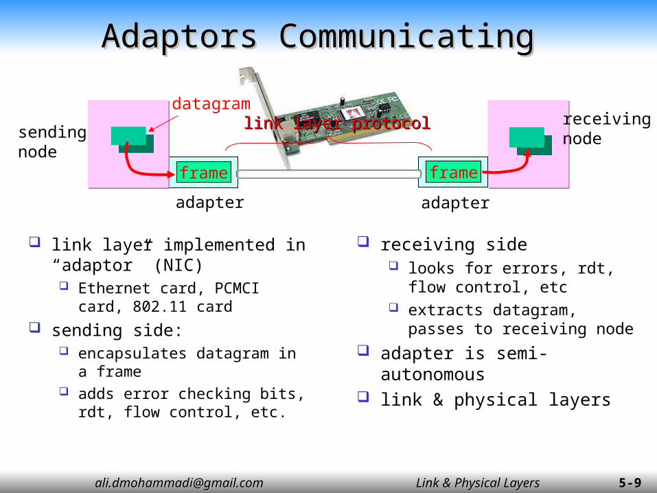
Adaptors CommunicatingAdaptors Communicating
link layer implemented in “adaptor” (NIC) Ethernet card, PCMCI card,
802.11 card sending side:
encapsulates datagram in a frame
adds error checking bits, rdt, flow control, etc.
receiving side looks for errors, rdt, flow
control, etc extracts datagram, passes
to receiving node adapter is semi-
autonomous link & physical layers
sendingnode
frame
receivingnode
datagram
frame
adapter adapter
link layer protocollink layer protocol

[email protected]@gmail.com Link & Physical LayersLink & Physical Layers 5-5-1010
Chapter 5 outlineChapter 5 outline
5.1 Introduction and services5.2 Error detection and correction 5.3 Links and Access Protocols5.4 Ethernet5.5 Ethernet Model5.6 Ethernet Frame Structure5.7 LAN addresses and ARP5.8 Ethernet Technologies5.9 Hubs, bridges, and switches5.10 Point to Point Protocol
[email protected]@gmail.com Link & Physical LayersLink & Physical Layers 5-5-1111
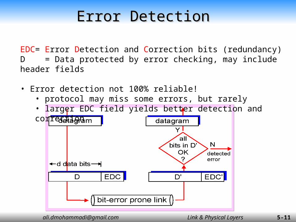
Error DetectionError Detection
EDC= Error Detection and Correction bits (redundancy)D = Data protected by error checking, may include header fields
• Error detection not 100% reliable!• protocol may miss some errors, but rarely• larger EDC field yields better detection and correction

[email protected]@gmail.com Link & Physical LayersLink & Physical Layers 5-5-1212
Internet checksumInternet checksum
Sender: treat segment contents
as sequence of 16-bit integers
checksum: addition (1’s complement sum) of segment contents
sender puts checksum value into UDP or TCP checksum field.
Receiver: compute checksum of
received segment check if computed checksum
equals checksum field value: NO - error detected YES - no error detected.
But maybe errors nonetheless? More later ….
Goal: detect “errors” (e.g., flipped bits) in transmitted segment (note: used at transport layer only)

[email protected]@gmail.com Link & Physical LayersLink & Physical Layers 5-5-1313
Checksumming: Cyclic Redundancy CheckChecksumming: Cyclic Redundancy Check
view data bits, D, as a binary number choose r+1 bit pattern (generator), G goal: choose r CRC bits, R, such that
<D,R> exactly divisible by G (modulo 2= add without carry)
receiver knows G, divides <D,R> by G. If non-zero remainder: error detected!
can detect all burst errors less than r+1 bits widely used in practice (ATM, HDCL)
D: data bits to be sent R: CRC bits
d [bits] r [bits]
bit patternbit pattern
mathematical formula: [D×2r XOR R]
[email protected]@gmail.com Link & Physical LayersLink & Physical Layers 5-5-1414
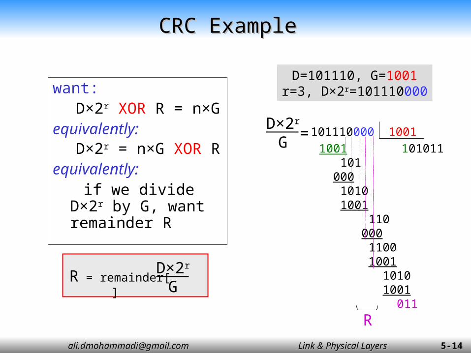
CRC ExampleCRC Example
want:D×2r XOR R = n×G
equivalently:D×2r = n×G XOR R
equivalently: if we divide D×2r by
G, want remainder R
R = remainder[ ]
D×2r
G
D=101110, G=1001r=3, D×2r=101110000
D×2r
G =101110000 10011001 101011 101 000 1010 1001 110 000 1100 1001 1010 1001 011
R

[email protected]@gmail.com Link & Physical LayersLink & Physical Layers 5-5-1515
Ethernet CRCEthernet CRC
Polynomial Presentation Based on use of polynomial codes Message frame and Generator thought of as binary
polynomials Example: 101101101 ~ x8 + x6 + x5 + x3 + x2 + x0
Ethernet CRC It is a CRC-32: It is 33 bit code that is uses as Generator:
G(x) = x32 + x26 + x23 + x22 + x16 + x12 + x11 + x10 + x8 + x7 + x5 + x4 + x2 + x + 1

[email protected]@gmail.com Link & Physical LayersLink & Physical Layers 5-5-1616
CRC PropertiesCRC Properties
Detect all single-bit errors if coefficients of xr and x0 of G(x) are one
Detect all double-bit errors, if G(x) has a factor with at least three terms
Detect all number of odd errors, if G(x) contains factor (x+1)
Detect all burst of errors smaller than r bits
[email protected]@gmail.com Link & Physical LayersLink & Physical Layers 5-5-1717
Chapter 5 outlineChapter 5 outline
5.1 Introduction and services5.2 Error detection and correction 5.3 Links and Access Protocols5.4 Ethernet5.5 Ethernet Model5.6 Ethernet Frame Structure5.7 LAN addresses and ARP5.8 Ethernet Technologies5.9 Hubs, bridges, and switches5.10 Point to Point Protocol
[email protected]@gmail.com Link & Physical LayersLink & Physical Layers 5-5-1818
hub
Client
Printer
Server
Client
LAN Switch
Client
Remote Access ServerModem pools
TelephoneLines
Router
External Link
Serversmodem
modem
Client
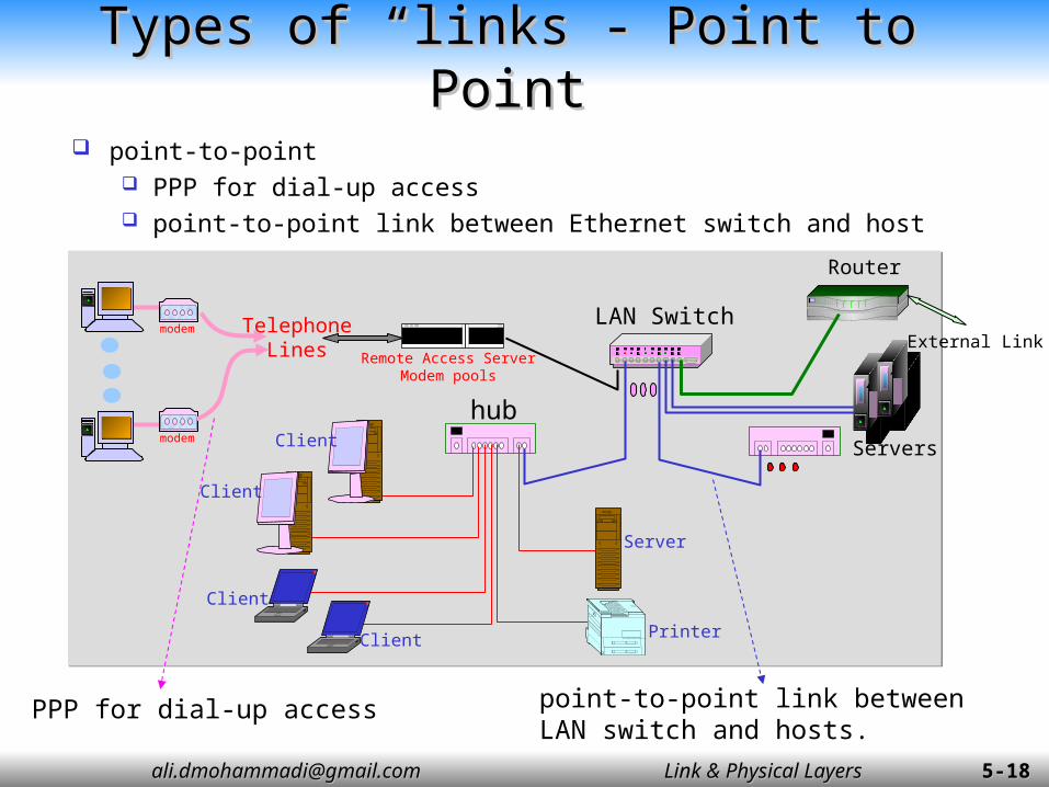
PPP for dial-up access point-to-point link between LAN switch and hosts.
point-to-point PPP for dial-up access point-to-point link between Ethernet switch and host
Types of “links”- Point to PointTypes of “links”- Point to Point
[email protected]@gmail.com Link & Physical LayersLink & Physical Layers 5-5-1919
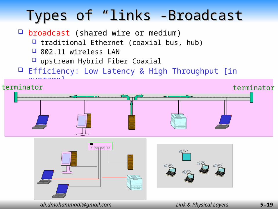
broadcast (shared wire or medium) traditional Ethernet (coaxial bus, hub) 802.11 wireless LAN upstream Hybrid Fiber Coaxial
Efficiency: Low Latency & High Throughput [in average]
Types of “links”-BroadcastTypes of “links”-Broadcast
terminatorterminator

[email protected]@gmail.com Link & Physical LayersLink & Physical Layers 5-5-2020
Ideal Broadcast Channel Access ProtocolIdeal Broadcast Channel Access Protocol
Broadcast channel of rate R bps When one node wants to transmit, it can send at rate
R.
When M nodes want to transmit, each can send at average rate R/M
Fully decentralized: no special node to coordinate transmissions
no synchronization of clocks, slots
Simple
[email protected]@gmail.com Link & Physical LayersLink & Physical Layers 5-5-2121
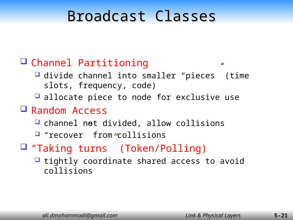
Channel Partitioning divide channel into smaller “pieces” (time slots,
frequency, code) allocate piece to node for exclusive use
Random Access channel not divided, allow collisions “recover” from collisions
“Taking turns” (Token/Polling) tightly coordinate shared access to avoid collisions
Broadcast ClassesBroadcast Classes

[email protected]@gmail.com Link & Physical LayersLink & Physical Layers 5-5-2222
Random Access ProtocolsRandom Access Protocols
When node has packet to send transmit at full channel data rate R. no a priori coordination among nodes
two or more transmitting nodes -> “collision”, random access MAC protocol specifies:
how to detect collisions how to recover from collisions (e.g., via delayed
retransmissions)
Examples of random access MAC protocols: slotted ALOHA ALOHA CSMA, CSMA/CD, CSMA/CA

[email protected]@gmail.com Link & Physical LayersLink & Physical Layers 5-5-2323
ALOHA (Pure, Slotted)ALOHA (Pure, Slotted)
All frames same size
Slotted: Time is divided into equal size slots 1 slot = time to transmit 1 frame
Pure: Time remains continues
Slotted: Nodes start to transmit frames only at beginning of slots
Pure: Nodes start to transmit whenever a frame is made.
Slotted: Nodes are synchronized Pure: Nodes are not synchronized
If 2 or more nodes transmit in slot, all nodes detect collision

[email protected]@gmail.com Link & Physical LayersLink & Physical Layers 5-5-2424
Suppose N nodes with many frames to send, each transmits in slot with probability p
probability that first node has success in a slot = p(1-p)N-1
probability that any node has a success is = Np(1-p)N-1
Suppose N nodes with many frames to send, each transmits in slot with probability p
probability that first node has success in a slot = p(1-p)N-1
probability that any node has a success is = Np(1-p)N-1
For max efficiency with N nodes, find pm that
maximizes Np(1-p)N-1
For many nodes, take limit of N pm(1- pm)N-1 as N
goes to infinity, gives 1/e = 0.37
For max efficiency with N nodes, find pm that
maximizes Np(1-p)N-1
For many nodes, take limit of N pm(1- pm)N-1 as N
goes to infinity, gives 1/e = 0.37
At best: channel used for useful transmissions 37% of time!
Slotted Aloha EfficiencySlotted Aloha Efficiency
[email protected]@gmail.com Link & Physical LayersLink & Physical Layers 5-5-2525
timet0t0-TF t0+TF
Vulnerableperiod
frame transmission
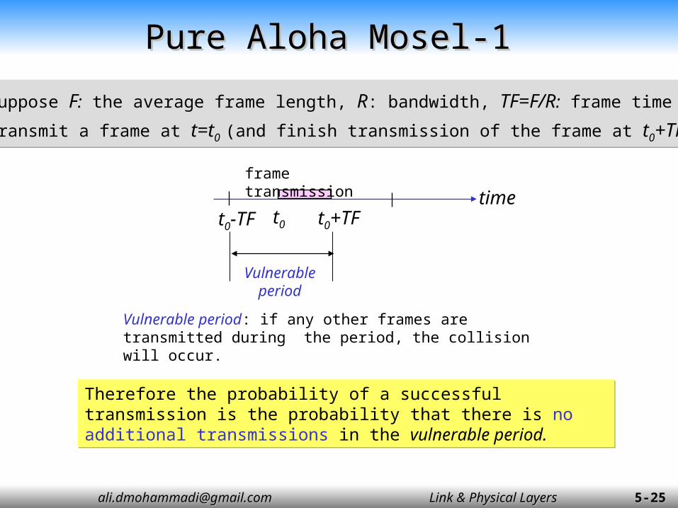
Suppose F: the average frame length, R: bandwidth, TF=F/R: frame time
Transmit a frame at t=t0 (and finish transmission of the frame at t0+TF )
Suppose F: the average frame length, R: bandwidth, TF=F/R: frame time
Transmit a frame at t=t0 (and finish transmission of the frame at t0+TF )
Vulnerable period: if any other frames are transmitted during the period, the collision will occur.
Therefore the probability of a successful transmission is the probability that there is no additional transmissions in the vulnerable period.
Therefore the probability of a successful transmission is the probability that there is no additional transmissions in the vulnerable period.
Pure Aloha Mosel-1Pure Aloha Mosel-1
[email protected]@gmail.com Link & Physical LayersLink & Physical Layers 5-5-2626
Pure Aloha Mosel-2Pure Aloha Mosel-2
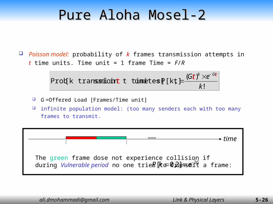
Poisson model: probability of k frames transmission attempts in t time units. Time unit = 1 frame Time = F/R
G =Offered Load [Frames/Time unit]
infinite population model: (too many senders each with too many frames to transmit.
!
)(t]P[k,unites] in t timession [k transmi Prob
k
eGt Gtk
!
)(t]P[k,unites] in t timession [k transmi Prob
k
eGt Gtk t
t t
time……
The green frame dose not experience collision if during Vulnerable period no one tries to transmit a frame: GekP 2]2,0[

[email protected]@gmail.com Link & Physical LayersLink & Physical Layers 5-5-2727
Throughput vs Offered Load- Pure AlohaThroughput vs Offered Load- Pure Aloha
frame a ofion transmisssuccessful ofy Probabilit Load Offered S frame a ofion transmisssuccessful ofy Probabilit Load Offered S
The throughput S is given by:
GeGS
GS2
frame a ofion transmisssuccessful a ofy Probabilit
GeGS
GS2
frame a ofion transmisssuccessful a ofy Probabilit

[email protected]@gmail.com Link & Physical LayersLink & Physical Layers 5-5-2828
Slotted ALOHA ModelSlotted ALOHA Model
Synchronize the transmissions of stations All stations keep track of transmission time slots and
are allowed to initiate transmissions only at the beginning of a time slot.
Suppose a packet occupies one time slot Vulnerable period is from t0-TF to t0, i.e., TF seconds
long. Therefore, the throughput of the system is:GekPP ]1,0[collision) no( GekPP ]1,0[collision) no(
GeGS
GS
frame a ofion transmisssuccessful a ofy ProbabilitGeGS
GS
frame a ofion transmisssuccessful a ofy Probabilit

[email protected]@gmail.com Link & Physical LayersLink & Physical Layers 5-5-2929
0 1 2 3 4 5 6 7 8 9 100
0.05
0.1
0.15
0.2
0.25
0.3
0.35
0.4
aloha
s-aloha
S-G Graphs-1S-G Graphs-1
GGeS
GGeS 2
Slotted ALOHA
(pure) Non-slotted ALOHA
0.37
0.18
0.5
G =Offered Load [Frame/Time unit]
S =
Thro
ughp
ut
[Fra
me/T
ime u
nit
]
[email protected]@gmail.com Link & Physical LayersLink & Physical Layers 5-5-3030
0 0.5 1 1.5 2 2.50
0.05
0.1
0.15
0.2
0.25
0.3
0.35
0.4
aloha
s-aloha
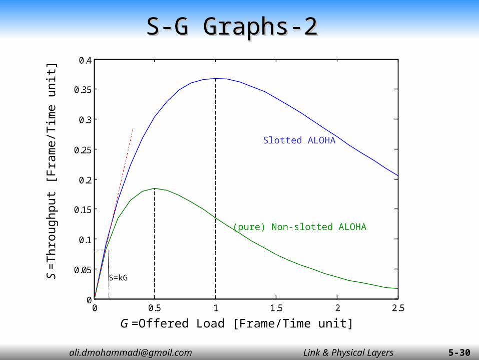
S-G Graphs-2S-G Graphs-2
Slotted ALOHA
(pure) Non-slotted ALOHA
G =Offered Load [Frame/Time unit]
S =
Thro
ughp
ut
[Fra
me/T
ime u
nit
]
S=kG

[email protected]@gmail.com Link & Physical LayersLink & Physical Layers 5-5-3131
Lack of collision controlLack of collision control
Collision ControlCollision Control
Offered load
Th
roughput
Controlled
Uncontrolled
[email protected]@gmail.com Link & Physical LayersLink & Physical Layers 5-5-3232
CSMA (Carrier Sense Multiple Access)CSMA (Carrier Sense Multiple Access)
CSMA: listen before transmit: If channel sensed idle: transmit entire frame If channel sensed busy, defer transmission
[email protected]@gmail.com Link & Physical LayersLink & Physical Layers 5-5-3333
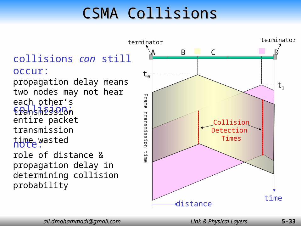
CSMA CSMA CCollisionsollisions
collisions can still occur:propagation delay means two nodes may not heareach other’s transmissioncollision:entire packet transmission time wastednote:role of distance & propagation delay in determining collision probability
A B C D
time
t0
t1
distance
CollisionDetection
Times
Fra
me tra
nsm
ission tim
e
terminatorterminator
[email protected]@gmail.com Link & Physical LayersLink & Physical Layers 5-5-3434
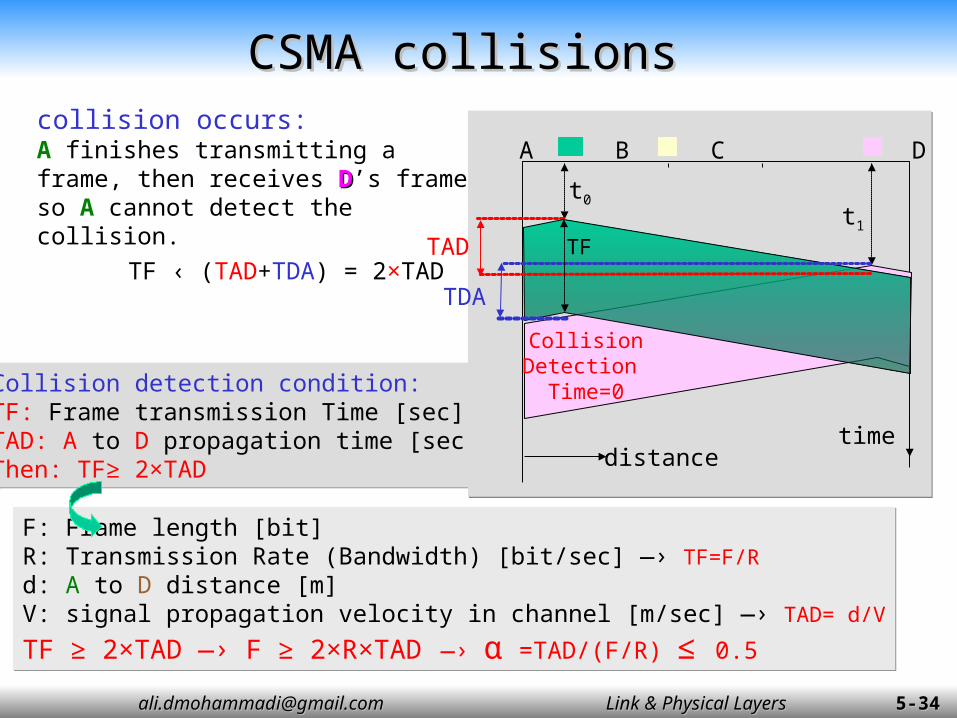
collision occurs:A finishes transmitting a frame, then receives DD’s frame so A cannot detect the collision.
F: Frame length [bit]R: Transmission Rate (Bandwidth) [bit/sec] —› TF=F/Rd: A to D distance [m]V: signal propagation velocity in channel [m/sec] —› TAD= d/V
TF ≥ 2×TAD —› F ≥ 2×R×TAD —› α =TAD/(F/R) ≤ 0.5
F: Frame length [bit]R: Transmission Rate (Bandwidth) [bit/sec] —› TF=F/Rd: A to D distance [m]V: signal propagation velocity in channel [m/sec] —› TAD= d/V
TF ≥ 2×TAD —› F ≥ 2×R×TAD —› α =TAD/(F/R) ≤ 0.5
Collision detection condition:TF: Frame transmission Time [sec]TAD: A to D propagation time [sec]Then: TF≥ 2×TAD
Collision detection condition:TF: Frame transmission Time [sec]TAD: A to D propagation time [sec]Then: TF≥ 2×TAD
A B C D
time
t0t1
distance
CollisionDetection Time=0
TAD
TDATF ‹ (TAD+TDA) = 2×TAD
TF
CSMA collisionsCSMA collisions
[email protected]@gmail.com Link & Physical LayersLink & Physical Layers 5-5-3838
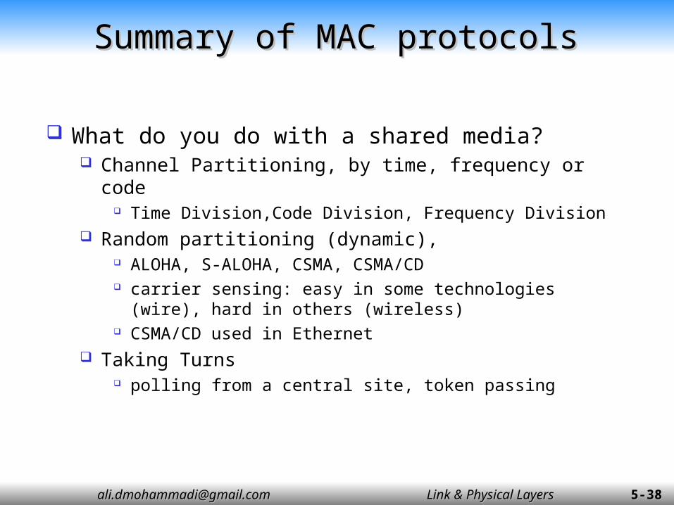
Summary of MAC protocolsSummary of MAC protocols
What do you do with a shared media? Channel Partitioning, by time, frequency or code
Time Division,Code Division, Frequency Division Random partitioning (dynamic),
ALOHA, S-ALOHA, CSMA, CSMA/CD carrier sensing: easy in some technologies (wire), hard
in others (wireless) CSMA/CD used in Ethernet
Taking Turns polling from a central site, token passing

[email protected]@gmail.com Link & Physical LayersLink & Physical Layers 5-5-3939
Chapter 5 outlineChapter 5 outline
5.1 Introduction and services5.2 Error detection and correction 5.3 Links and Access Protocols5.4 Ethernet5.5 Ethernet Model5.6 Ethernet Frame Structure5.7 LAN addresses and ARP5.8 Ethernet Technologies5.9 Hubs, bridges, and switches5.10 Point to Point Protocol

[email protected]@gmail.com Link & Physical LayersLink & Physical Layers 5-5-4040Figure 6.11
IEEE 802 LAN standardsIEEE 802 LAN standards
MAC
LLC
Network Layer
802.2 Logical Link Control
802.3CSMA-CD
802.5Token Ring
802.11Wireless
LAN
OtherLANs
Various Physical Layers
Network Layer
Data Link Layer
Physical Layer
One LLC and several MACs, each MAC has an associated set of physical layers.
MAC provides connectionless transfer. Generally no error control because of relatively error free.
Ethernet consists of 802.2 + 802.3 + a physical layer

[email protected]@gmail.com Link & Physical LayersLink & Physical Layers 5-5-4141
“dominant” LAN technology: Cheap even for 100Mbs! First widely used LAN technology Simpler, cheaper than token LANs and ATM Kept up with speed race: 10, 100, 1000, 10000, 40000
Mbps
Metcalfe’s EthernetSketch, 1973, Xerox.
EthernetEthernet

[email protected]@gmail.com Link & Physical LayersLink & Physical Layers 5-5-4242
Ethernet uses CSMA/CDEthernet uses CSMA/CD
No slots Adapter doesn’t
transmit if it senses that some other adapter is transmitting, that is, carrier sense
Transmitting adapter aborts when it senses that another adapter is transmitting, that is, collision detection
Before attempting a retransmission, adapter waits a random time, that is, random access.
Adapter keeps trying to transmit, that is, multiple access.

[email protected]@gmail.com Link & Physical LayersLink & Physical Layers 5-5-4343
Ethernet CSMA/CD algorithmEthernet CSMA/CD algorithm
1. Adaptor gets datagram and creates frame
2. If adapter senses channel idle, it starts to transmit frame. If it senses channel busy, waits until channel idle and then transmits
3. If adapter transmits entire frame without detecting another transmission, the adapter is done with frame !
1. Adaptor gets datagram and creates frame
2. If adapter senses channel idle, it starts to transmit frame. If it senses channel busy, waits until channel idle and then transmits
3. If adapter transmits entire frame without detecting another transmission, the adapter is done with frame !
4. If adapter detects another transmission while transmitting, aborts and sends jam signal
5. After aborting, adapter enters exponential backoff: after the mth collision, adapter chooses a K at random from {0,1,2,…,2m-1}. Adapter waits K×512 bit times and returns to Step 2

[email protected]@gmail.com Link & Physical LayersLink & Physical Layers 5-5-4444
Frame Ready for Transmission
Sense Channel
Channel BusyNo
Frame Transmission & Channel Sense
BusyCollisionAbort Transmission;Send Jam Signal(3Bytes)
Frame successfully transmittedFrame successfully transmittedFrame successfully transmittedFrame successfully transmitted
Yes
Wait Inter-frame Gap9.6 μs
Increment AttemptsN++
Too Many Attempts?
Unsuccessful transmission, Excessive CollisionsUnsuccessful transmission, Excessive CollisionsUnsuccessful transmission, Excessive CollisionsUnsuccessful transmission, Excessive Collisions
Ethernet MAC flow in Half-Duplex Mode-Ethernet MAC flow in Half-Duplex Mode-TransmissionTransmission
Inter-frame Gap allows receivers time to settle
N=15 N<15
N<10
yes No
K=N K=10
Select A Random Integer R=(0 to 2k-1)
wait R×512 bit times
Set Attempt N=0Exponential backoff
[email protected]@gmail.com Link & Physical LayersLink & Physical Layers 5-5-4545
Ethernet’s CSMA/CD (more)Ethernet’s CSMA/CD (more)
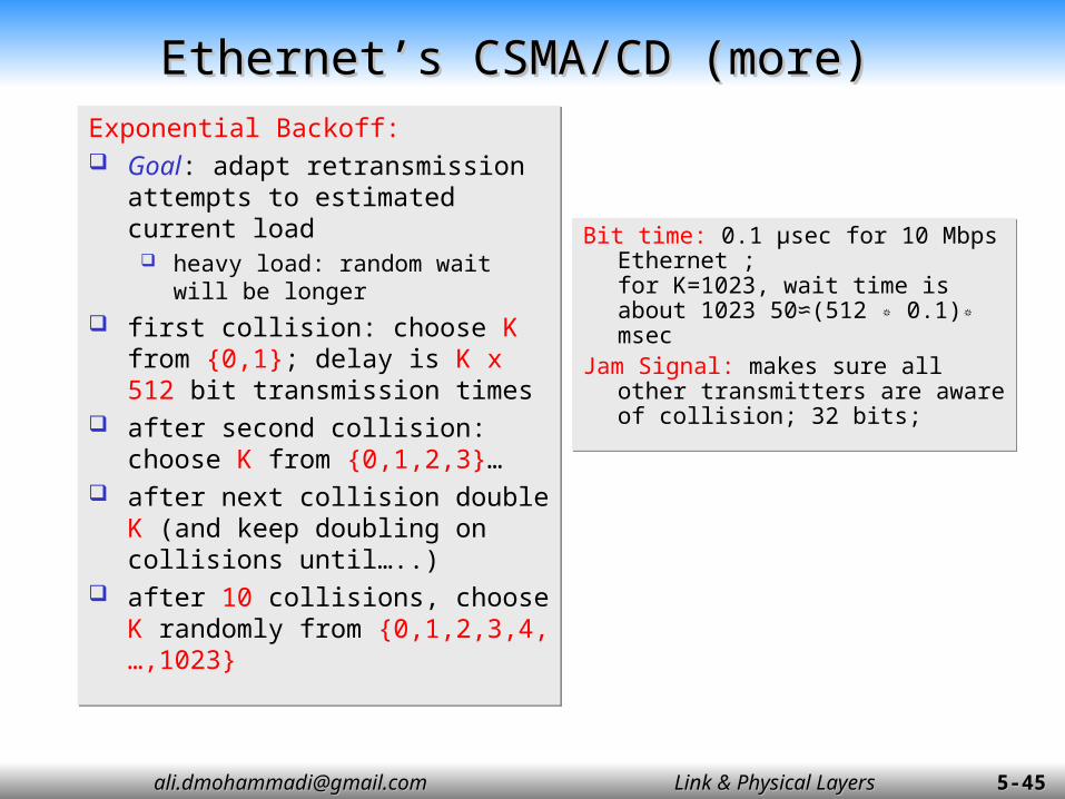
Bit time: 0.1 µsec for 10 Mbps Ethernet ;for K=1023, wait time is about 1023 50≈(512 ٭ 0.1)٭ msec
:Jam Signal makes sure all other transmitters are aware of ;collision; 32 bits
:Bit time µsec for 10 Mbps 0.1 ; Ethernet for K=1023, wait time is about 1023 50≈(512 ٭ 0.1)٭ msec
Jam Signal: makes sure all other transmitters are aware of collision; 32 bits;
Exponential Backoff: Goal: adapt retransmission
attempts to estimated current load
heavy load: random wait will be longer
first collision: choose K from {0,1}; delay is K x 512 bit transmission times
after second collision: choose K from {0,1,2,3}…
after next collision double K (and keep doubling on collisions until…..)
after 10 collisions, choose K randomly from {0,1,2,3,4,…,1023}
[email protected]@gmail.com Link & Physical LayersLink & Physical Layers 5-5-4646
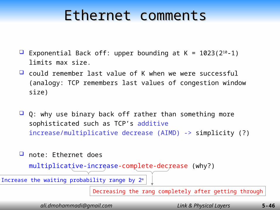
Ethernet commentsEthernet comments
Exponential Back off: upper bounding at K = 1023(210-1) limits max size.
could remember last value of K when we were successful (analogy: TCP remembers last values of congestion window size)
Q: why use binary back off rather than something more sophisticated such as TCP’s additive increase/multiplicative decrease (AIMD) -> simplicity (?)
note: Ethernet does
multiplicative-increase-complete-decrease (why?)Increase the waiting probability range by 2m
Decreasing the rang completely after getting through

[email protected]@gmail.com Link & Physical LayersLink & Physical Layers 5-5-4747
Ethernet MAC flow in Half-Duplex Mode-Ethernet MAC flow in Half-Duplex Mode-ReceiveReceive
Receive Process
Channel SenseIdle
Busy
Start Receiving
Channel Sense
Received Frame too Small? (Jam Signal)
RecognizeAddress?
Valid Frame Check Sequence?
Extra bits?
Receive Alignment ErrorReceive Frame Check Error
SuccessfulReception
Busy
Idle
Yes
No
No
YesNo
Yes
Yes
No

[email protected]@gmail.com Link & Physical LayersLink & Physical Layers 5-5-4848
Ethernet’s use of randomizationEthernet’s use of randomization
More collisionsMore collisions
Heavier Load, more nodes trying to sendHeavier Load, more nodes trying to send
Randomize retransmissions over longer time interval, to reduce collision probability
Randomize retransmissions over longer time interval, to reduce collision probability

[email protected]@gmail.com Link & Physical LayersLink & Physical Layers 5-5-4949
Chapter 5 outlineChapter 5 outline
5.1 Introduction and services5.2 Error detection and correction 5.3 Links and Access Protocols5.4 Ethernet5.5 Ethernet Model
Ethernet and RandomizationEthernet Model (throughput, response time,
efficiency)5.6 Ethernet Frame Structure 5.7 LAN addresses and ARP5.8 Ethernet Technologies5.9 Hubs, bridges, and switches5.10 Point to Point Protocol
[email protected]@gmail.com Link & Physical LayersLink & Physical Layers 5-5-5050
Ethernet ModelEthernet Model
An analytical model for Ethernet is developed. The model includes
Throughput, Response Time and Efficiency (Utilization)

[email protected]@gmail.com Link & Physical LayersLink & Physical Layers 5-5-5151
Model AssumptionsModel Assumptions
Large number of active nodes, with each node having a large number of frames to send.
Fixed length frames. The packets transmission probability is Poisson. Poisson model: probability of k packets transmission attempts
in t time units
infinite population model
!
)(
k
eGtt]P[k,unites] time t in ontransmissi [k Prob
Gtk
!
)(
k
eGtt]P[k,unites] time t in ontransmissi [k Prob
Gtk

[email protected]@gmail.com Link & Physical LayersLink & Physical Layers 5-5-5252
Frame transmission time is unit of time (F/R).
Throughput S - number of frames successfully (without collision) transmitted per unit time.
Offered load G - number frames transmissions attempted per unit time.
Note: S <= G,
S depends on G.
Model ParametersModel Parameters

[email protected]@gmail.com Link & Physical LayersLink & Physical Layers 5-5-5353
Throughput ModelThroughput Model
busy time is a random variable given by B
idle time is a random variable given by I
collision time is a random variable given by C
time……
][][][ CEBEIE
frame a of ontransmissi l successfuofy ProbabilitS
The throughput S is given by:

[email protected]@gmail.com Link & Physical LayersLink & Physical Layers 5-5-5454
Throughput vs Offered Load-Average Idle TimeThroughput vs Offered Load-Average Idle Time
Because it is a Poisson Process then:I is a variable with an exponential distribution with expected value =1/G
GIE
1][ Average (Accepted) idle time =
G: Average offered load per unit time.1/G: Average time between two consecutive transmission.
Idle time:

[email protected]@gmail.com Link & Physical LayersLink & Physical Layers 5-5-5555
Throughput vs Offered Load-Average Busy TimeThroughput vs Offered Load-Average Busy Time
1+α
αtime
no one transmits GekP ],0[
frame clear the channelsuccessful frame transmission busy time length =B= (1+ α)
GeBE )1(][Average (Accepted) busy time =
A successful packet transmission:
= end-to-end propagation time/unit timetime during which collisions can occur
Probability of successful transmission of a frame
5.0/
/
RF
vd 5.0/
/
RF
vd
α

[email protected]@gmail.com Link & Physical LayersLink & Physical Layers 5-5-5656
Throughput vs Offered Load-Average Collision TimeThroughput vs Offered Load-Average Collision Time
)1()5.0(][ GeCE Average (Accepted) collision time =
A collision in the channel:
transmission GekPkP 1],0[1],0[
timeα
A frame enters into channel
Any transmissioncauses collision
timeα
Channel cleared
Collision time length = α
timeα α
Collision time length = 2α
Channel cleared
Collision time length = 1.5 α

[email protected]@gmail.com Link & Physical LayersLink & Physical Layers 5-5-5757
Average ThroughputAverage Throughput
)1(5.1)1(1)1(5.1)1(1 GG
G
GG
G
eGGe
Ge
eeG
eS
)1(5.1)1(1)1(5.1)1(1 GG
G
GG
G
eGGe
Ge
eeG
eS
44.51
1
21
154.0
10
2max
e
S then e
G for 44.51
1
21
154.0
10
2max
e
S then e
G for
][][][ CEBEIE
frame a of ontransmissi l successfuofy ProbabilitS
The throughput S is given by:
frames/Unit timeframes/Unit time
[email protected]@gmail.com Link & Physical LayersLink & Physical Layers 5-5-5858
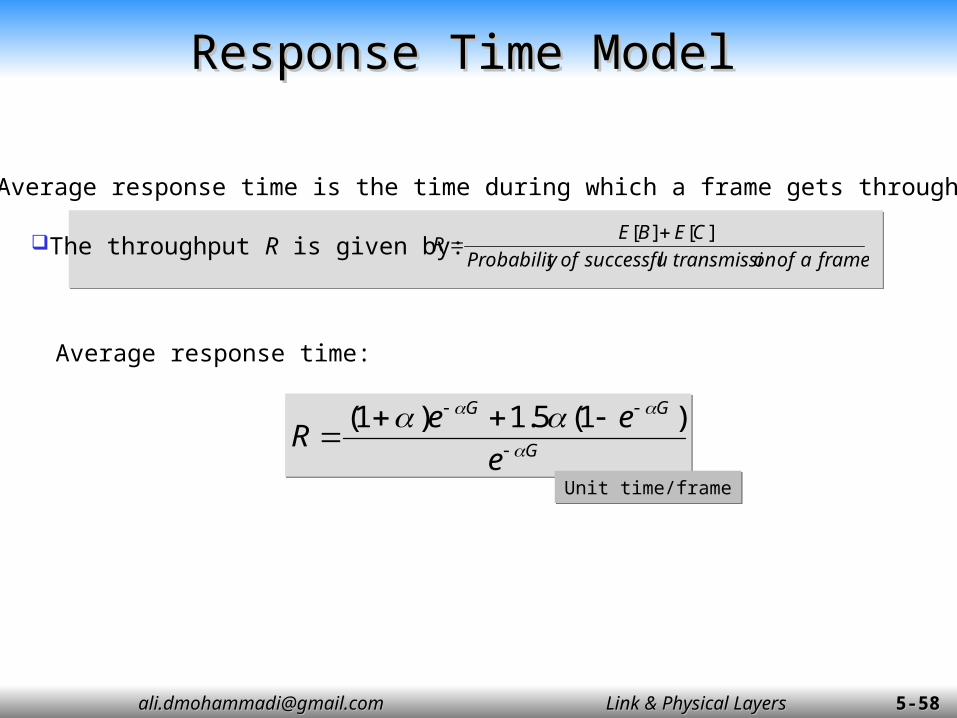
Response Time ModelResponse Time Model
G
GG
e
eeR
)1(5.1)1(G
GG
e
eeR
)1(5.1)1(
Average response time:
Unit time/frameUnit time/frame
Average response time is the time during which a frame gets through.
frame a of ontransmissi l successfuofy Probabilit
CEBER
][][ The throughput R is given by:

[email protected]@gmail.com Link & Physical LayersLink & Physical Layers 5-5-5959
0 5 10 15 20 25 30 35 40 45 500
0.1
0.2
0.3
0.4
0.5
0.6
0.7
0.8
0.9
1
a=0.01
a=0.02
a=0.05
a=0.1
a=0.2
S-G Graphs-1S-G Graphs-1
G=Offered Load [Frames/unit time]
S=Thro
ughput
[Fra
mes/
un
it t
ime]
capacity of CSMA/CD: maximum value of S over all values of G
>
α=0.1 means “10% of frame get transmitted before every one on the channel hears (detects) it”.α=0.1 means “10% of frame get transmitted before every one on the channel hears (detects) it”.
α=0.01α=0.02α=0.05α=0.1α=0.2>
>
>
>
>
[email protected]@gmail.com Link & Physical LayersLink & Physical Layers 5-5-6060
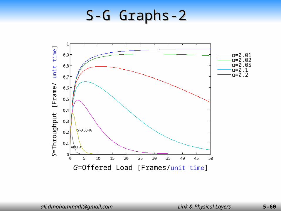
S-G Graphs-2S-G Graphs-2
0 5 10 15 20 25 30 35 40 45 500
0.1
0.2
0.3
0.4
0.5
0.6
0.7
0.8
0.9
1
G=Offered Load [Frames/unit time]
S=Thro
ughput
[Fra
me/
un
it t
ime]
α=0.01α=0.02α=0.05α=0.1α=0.2
ALOHA
S-ALOHA

[email protected]@gmail.com Link & Physical LayersLink & Physical Layers 5-5-6161
Lack of collision controlLack of collision control
Collision ControlCollision Control
Offered load
Th
roughput
Controlled
Uncontrolled

[email protected]@gmail.com Link & Physical LayersLink & Physical Layers 5-5-6262
R-G GraphsR-G Graphs
α = 0.01
α = 0.02
G=Offered Load [Frame/unit time]
R =
Resp
on
se t
ime [
un
it t
ime]
1.02
1.01
0 10 20 30 40 500
5
10
15
20
25
1. 1
G=Offered Load [Frame/unit time]
R =
Resp
on
se t
ime [
un
it t
ime]
α = 0.1
0 5 10 15 20 250
10
20
30
40
50
α = 0.2
G=Offered Load [Frame/unit time]
R =
Resp
on
se t
ime [
un
it t
ime]
1.2
0 20 40 60 80 1000
5
10
15
α = 0.05
G=Offered Load [Frame/unit time]
R =
Resp
on
se t
ime [
un
it t
ime]
1.05
0 20 40 60 80 1001
1.05
1.1
1.15
1.2
1.25
α =0 .01
α =0 .02

[email protected]@gmail.com Link & Physical LayersLink & Physical Layers 5-5-6363
Efficiency ModelEfficiency Model
)1(5.1)1(
)1(3
)1(5.1)1(/1
)1(2
)1(5.1)1(/1
)1(1
2
GG
G
GG
G
GG
G
ee
e
time contentiontime ntransmisio frame
time ntransmisio frameefficiency
eeG
ethroughputtime serviceefficiency
eeG
e
time elapse
time ntransmisio frameefficiency
)1(5.1)1(
)1(3
)1(5.1)1(/1
)1(2
)1(5.1)1(/1
)1(1
2
GG
G
GG
G
GG
G
ee
e
time contentiontime ntransmisio frame
time ntransmisio frameefficiency
eeG
ethroughputtime serviceefficiency
eeG
e
time elapse
time ntransmisio frameefficiency
[email protected]@gmail.com Link & Physical LayersLink & Physical Layers 5-5-6464
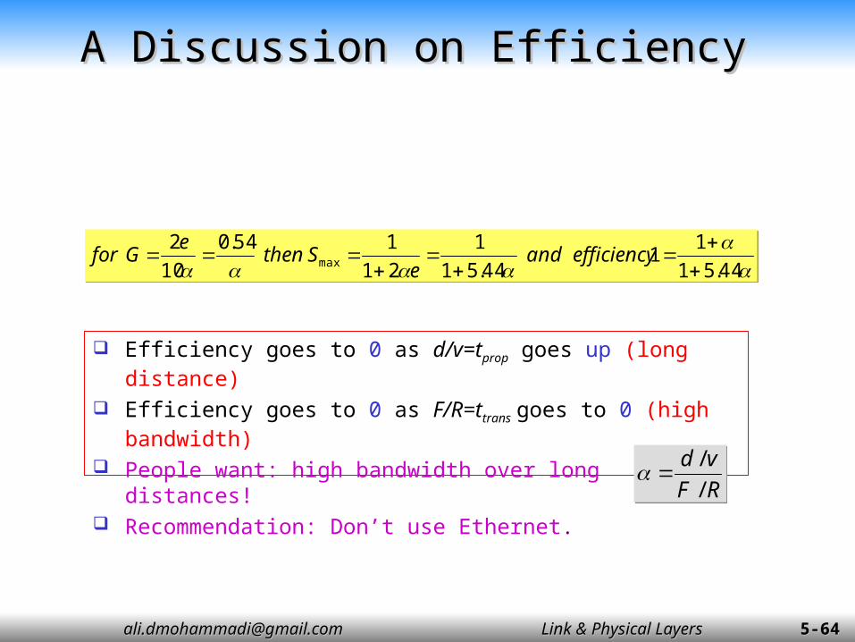
A Discussion on EfficiencyA Discussion on Efficiency
44.51
11
44.51
1
21
154.0
10
2max
efficiency and
eS then
eG for
44.51
11
44.51
1
21
154.0
10
2max
efficiency and
eS then
eG for
Efficiency goes to 0 as d/v=tprop goes up (long distance)
Efficiency goes to 0 as F/R=ttrans goes to 0 (high bandwidth)
People want: high bandwidth over long distances! Recommendation: Don’t use Ethernet.
RF
vd
/
/
RF
vd
/
/

[email protected]@gmail.com Link & Physical LayersLink & Physical Layers 5-5-6565
Efficiency2Efficiency2
0 5 10 15 20 25 30 35 40 45 500
0.1
0.2
0.3
0.4
0.5
0.6
0.7
0.8
0.9
a=0.01
a=0.02
a=0.05a=0.1
a=0.2
G=Offered Load [Frames/unit time]
α=0.01α=0.02α=0.05α=0.1α=0.2
)1(5.1)1(/1
)1( 2
2
GG
G
eeG
ethroughputtimeserviceefficiency
)1(5.1)1(/1
)1( 2
2
GG
G
eeG
ethroughputtimeserviceefficiency
[email protected]@gmail.com Link & Physical LayersLink & Physical Layers 5-5-6666
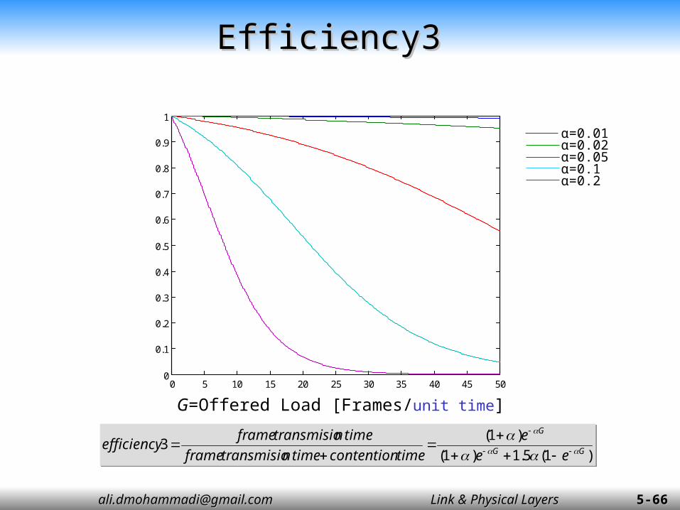
Efficiency3Efficiency3
0 5 10 15 20 25 30 35 40 45 500
0.1
0.2
0.3
0.4
0.5
0.6
0.7
0.8
0.9
1
a=0.01
a=0.02
a=0.05a=0.1
a=0.2
G=Offered Load [Frames/unit time]
α=0.01α=0.02α=0.05α=0.1α=0.2
)1(5.1)1(
)1(3
GG
G
ee
e
time contentiontime ntransmisio frame
time ntransmisio frame efficiency
)1(5.1)1(
)1(3
GG
G
ee
e
time contentiontime ntransmisio frame
time ntransmisio frame efficiency

[email protected]@gmail.com Link & Physical LayersLink & Physical Layers 5-5-6767
Chapter 5 outlineChapter 5 outline
5.1 Introduction and services5.2 Error detection and correction 5.3 Links and Access Protocols5.4 Ethernet5.5 Ethernet Model5.6 Ethernet Frame Structure5.7 LAN addresses and ARP5.8 Ethernet Technologies5.9 Hubs, bridges, and switches5.10 Point to Point Protocol

[email protected]@gmail.com Link & Physical LayersLink & Physical Layers 5-5-6868
Sending adapter encapsulates IP datagram (or other network layer protocol packet) in Ethernet frame
Preamble: 7 bytes with pattern 10101010 followed by one
byte with pattern 10101011 used to synchronize receiver, sender clock rates
PAD
46 to 1500 Bytes8B 6B 6B
(2B)
4B
Mini :6+6+2+46+4= 64 Bytes (512 bits)Max :6+6+2+1500+4= 1518 Bytes
Ethernet Frame Structure-1Ethernet Frame Structure-1

[email protected]@gmail.com Link & Physical LayersLink & Physical Layers 5-5-6969
Addresses: 6 bytes if adapter receives frame with matching destination
address, or with broadcast address (e.g. ARP packet), it passes data in frame to network layer protocol
otherwise, adapter discards frame
Type: indicates the higher layer protocol, mostly IP but others may be supported such as Novell IPX and AppleTalk)
CRC: checked at receiver, if error is detected, the frame is simply dropped
Ethernet Frame Structure-2Ethernet Frame Structure-2

[email protected]@gmail.com Link & Physical LayersLink & Physical Layers 5-5-7070
Unreliable, connectionless serviceUnreliable, connectionless service
Connectionless: No handshaking between sending and receiving adapter.
Unreliable: receiving adapter doesn’t send ACKs or NACKs to sending adapter stream of datagrams passed to network layer can have
gaps gaps will be filled if application is using TCP otherwise, application will see the gaps

[email protected]@gmail.com Link & Physical LayersLink & Physical Layers 5-5-7171
Chapter 5 outlineChapter 5 outline
5.1 Introduction and services5.2 Error detection and correction 5.3 Links and Access Protocols5.4 Ethernet5.5 Ethernet Model5.6 Ethernet Frame Structure5.7 LAN addresses and ARP5.8 Ethernet Technologies5.9 Hubs, bridges, and switches5.10 Point to Point Protocol

[email protected]@gmail.com Link & Physical LayersLink & Physical Layers 5-5-7272
LAN Addresses and ARPLAN Addresses and ARP
32-bit IP address: network-layer address used to get datagram to destination IP network (recall IP
network definition)
LAN (or MAC or physical or Ethernet) address: used to get datagram from one interface to another
physically-connected interface (same network) 48 bit MAC address (for most LANs)
burned in the adapter ROM
[email protected]@gmail.com Link & Physical LayersLink & Physical Layers 5-5-7373
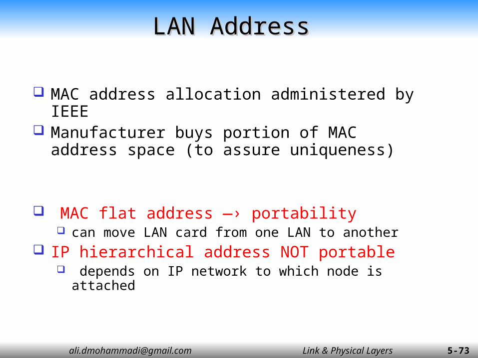
LAN AddressLAN Address
MAC address allocation administered by IEEE Manufacturer buys portion of MAC address
space (to assure uniqueness)
MAC flat address —› portability can move LAN card from one LAN to another
IP hierarchical address NOT portable depends on IP network to which node is attached

[email protected]@gmail.com Link & Physical LayersLink & Physical Layers 5-5-7474
Ethernet Address FormatEthernet Address Format
Every vendor (e.g., 3COM) is assigned a vendor block code.
Therefore, every globally administered address is globally unique.

[email protected]@gmail.com Link & Physical LayersLink & Physical Layers 5-5-7575
LAN Addresses and ARP-1LAN Addresses and ARP-1
1A-23-F9-CD-06-9B
8B-B2-2F-54-1A-0F
49-BD-D2-C7-56-2A
5C-66-AB-90-75-B161-BC-85-50-C1-7B
B1-C6-A1-0B-B9-80
LANLAN
240.108.12.01
240.108.12.02
240.108.12.03
240.108.12.04
240.108.12.05
240.108.12.06
Each Adapter on LAN has unique LAN address
Network Interface Card (Network Interface Card (AdaptorAdaptor))
[email protected]@gmail.com Link & Physical LayersLink & Physical Layers 5-5-7676
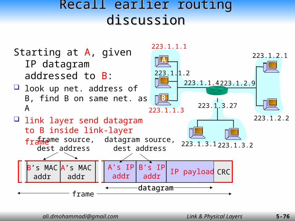
Recall earlier routing discussionRecall earlier routing discussion
Starting at A, given IP datagram addressed to B:
look up net. address of B, find B on same net. as A
link layer send datagram to B inside link-layer frame
223.1.1.1
223.1.1.2
223.1.1.3
223.1.1.4 223.1.2.9
223.1.2.2
223.1.2.1
223.1.3.2223.1.3.1
223.1.3.27
A
B
datagram
B’s MACaddr
A’s MACaddr
A’s IPaddr
B’s IPaddr
IP payload
frame source,dest address
datagram source,dest address
CRC
framedatagram

[email protected]@gmail.com Link & Physical LayersLink & Physical Layers 5-5-7777
ARP: Address Resolution ProtocolARP: Address Resolution Protocol
Each IP node (Host, Router) on LAN has ARP table
ARP Table: IP/MAC address mappings for some LAN nodes
< IP address; MAC address; TTL> TTL (Time To Live): time
after which address mapping will be forgotten (typically 20 min)
Question: how to determineMAC address of Bknowing B’s IP address?
Question: how to determineMAC address of Bknowing B’s IP address?
223.1.1.1
223.1.1.2
223.1.1.3
223.1.1.4 223.1.2.9
223.1.2.2
223.1.2.1
223.1.3.2223.1.3.1
223.1.3.27
A
B

[email protected]@gmail.com Link & Physical LayersLink & Physical Layers 5-5-7878
Operation of ARPOperation of ARP
FTP
TCP
IP
Ethernet driver
ARP
TCP
resolver
IPARP
Ethernet driver
Ethernet driver
ARP
hostnamehostname
IP addr Establish connection with IP address
Send IP datagram to IP address
ARP request (Ethernet broadcast)
(4)(5)
(6)
(3)
(1)
(2)
(7)
(8) (9)
A
B
LAN

[email protected]@gmail.com Link & Physical LayersLink & Physical Layers 5-5-7979
Routing to inside a LANRouting to inside a LAN
A wants to send datagram to B, and A knows B’s IP address.
Suppose B’s MAC address is not in A’s ARP table.
A broadcasts ARP query packet, containing B's IP address all machines on LAN
receive ARP query B receives ARP packet,
replies to A with its (B's) MAC address frame sent to A’s MAC
address (unicast)
A caches (saves) IP-to-MAC address pair in its ARP table until information becomes old (times out) soft state: information
that times out (goes away) unless refreshed
ARP is “plug-and-play”: nodes create their ARP
tables without intervention from network administrator

[email protected]@gmail.com Link & Physical LayersLink & Physical Layers 5-5-8080
Routing to another LANRouting to another LAN
LAN1LAN1
1A-23-F9-CD-06-9B240.108.12.01 49-BD-D2-C7-56-2A
240.108.12.03
61-BC-85-50-C1-7B
240.108.12.02 LAN2LAN2
B1-C6-A1-0B-B9-80
40.211.7.200
40.211.7.20033-5A-18-0E-CC-12
AB
walkthrough: send datagram from A to B via R (assume A knows B’s IP address)
walkthrough: send datagram from A to B via R (assume A knows B’s IP address)
Two ARP tables in router, one for each IP network (LAN) In ARP table at source, find R’s MAC address 49-BD-D2-C7-56-
2A
Two ARP tables in router, one for each IP network (LAN) In ARP table at source, find R’s MAC address 49-BD-D2-C7-56-
2A

[email protected]@gmail.com Link & Physical LayersLink & Physical Layers 5-5-8181
A creates datagram with source A, destination B A uses ARP to get R’s MAC address for
240.108.12.03 A creates link-layer frame with R's MAC address
as destination, frame contains A-to-B IP datagram
A’s data link layer sends frame R’s data link layer receives frame R removes IP datagram from Ethernet frame,
sees its destined to B R uses ARP to get B’s physical layer address R creates frame containing A-to-B IP datagram
sends to B
Routing to another LAN’Routing to another LAN’

[email protected]@gmail.com Link & Physical LayersLink & Physical Layers 5-5-8282
Chapter 5 outlineChapter 5 outline
5.1 Introduction and services5.2 Error detection and correction 5.3 Links and Access Protocols5.4 Ethernet5.5 Ethernet Model5.6 Ethernet Frame Structure5.7 LAN addresses and ARP5.8 Ethernet Technologies5.9 Hubs, bridges, and switches5.10 Point to Point Protocol

[email protected]@gmail.com Link & Physical LayersLink & Physical Layers 5-5-8383
10: 10Mbps; 2: under 200 meters max cable length thin coaxial cable in a bus topology
repeaters used to connect up to multiple segments repeater repeats bits it hears on one interface to its other interfaces: physical layer device only! has become a legacy technology
Ethernet Technologies: 10Base2Ethernet Technologies: 10Base2
[email protected]@gmail.com Link & Physical LayersLink & Physical Layers 5-5-8484
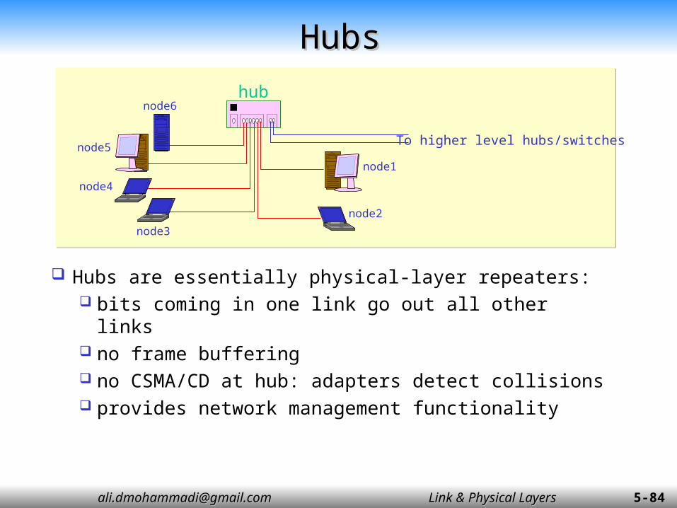
Hubs are essentially physical-layer repeaters: bits coming in one link go out all other links no frame buffering no CSMA/CD at hub: adapters detect
collisions provides network management functionality
HubsHubshub
node1
node2
node3
node4
node5
node6
To higher level hubs/switches

[email protected]@gmail.com Link & Physical LayersLink & Physical Layers 5-5-8585
Used in 10BaseT, 10Base2 Each bit has a transition Allows clocks in sending and receiving nodes
to synchronize to each other no need for a centralized, global clock among nodes!
This is physical-layer!
Used in 10BaseT, 10Base2 Each bit has a transition Allows clocks in sending and receiving nodes
to synchronize to each other no need for a centralized, global clock among nodes!
This is physical-layer!
Manchester EncodingManchester Encoding

[email protected]@gmail.com Link & Physical LayersLink & Physical Layers 5-5-8686
IEEE 802.3 10Mbps MediumsIEEE 802.3 10Mbps Mediums
Coaxial Cable(50
Ohm)
Coaxial Cable (50
Ohm)
Unshielded twisted pair
850-nm optical fiber
pair
Baseband (Manchester)
Baseband (Manchester)
Baseband (Manchester
)
Manchester/On-Off
Bus Bus Star Star
500 185 100 500
100 30 ---- 33
10 5 0.4 to 0.662.5/12.5
µm
10Base5 10Base2 10Base-T 10base-FP
Transmissionmedium
Signalingtechnology
Topology
Max segmentlength [m]
Nodes persegment
Cable diameter[mm]

[email protected]@gmail.com Link & Physical LayersLink & Physical Layers 5-5-8787
2 pair, STP2 pair,
Category 5 UTP
2 optical fibers
4 pair, cat.3, 4 or
5 UTP
MLT-3 MLT-3 4B5B, NRZI 8B6T, NRZ
100 Mbps 100 Mbps 100 Mbps 100 Mbps
100 100 100 100
200 200 400 200
100Base-TX 100Base-FX 100Base-T4
Transmissionmedium
Signalingtechnology
Data rate
Max segmentlength [m]
Networkspan [m]
IEEE 802.3 100Mbps MediumsIEEE 802.3 100Mbps Mediums
STP: Shielded twisted pair; UTP: Unshielded twisted pairNRZ: NonReturn to Zero; NRZI: NRZ Invertwd

[email protected]@gmail.com Link & Physical LayersLink & Physical Layers 5-5-8888
Gbit EthernetGbit Ethernet
use standard Ethernet frame format allows for point-to-point links and shared
broadcast channels in shared mode, CSMA/CD is used; short
distances between nodes to be efficient uses hubs, called here “Buffered Distributors” Full-Duplex at 1 Gbps for point-to-point links 10 or 40 Gbps now !

[email protected]@gmail.com Link & Physical LayersLink & Physical Layers 5-5-8989
Chapter 5 outlineChapter 5 outline
5.1 Introduction and services5.2 Error detection and correction 5.3 Links and Access Protocols5.4 Ethernet5.5 Ethernet Model5.6 Ethernet Frame Structure5.7 LAN addresses and ARP5.8 Ethernet Technologies5.9 Hubs, bridges, and switches5.10 Point to Point Protocol

[email protected]@gmail.com Link & Physical LayersLink & Physical Layers 5-5-9090
Interconnecting LAN segmentsInterconnecting LAN segments
Hubs Bridges Switches
Remark: switches are essentially multi-port bridges. What we say about bridges also holds for switches!

[email protected]@gmail.com Link & Physical LayersLink & Physical Layers 5-5-9393
Bridges: Traffic IsolationBridges: Traffic Isolation
Bridge installation breaks LAN into LAN segments Bridges filter packets:
Same-LAN-segment frames not usually forwarded onto other LAN segments
Segments become separate collision domains
bridge collision domain
collision domain
= hub
= host
LAN (IP network)
LAN segment LAN segment

[email protected]@gmail.com Link & Physical LayersLink & Physical Layers 5-5-9494
ForwardingForwarding
How do determine to which LAN segment to forward frame?• Looks like a routing problem...

[email protected]@gmail.com Link & Physical LayersLink & Physical Layers 5-5-9595
Self learningSelf learning
A bridge has a bridge table Entry in bridge table:
(Node LAN Address, Bridge Interface, Time Stamp) Stale entries in table dropped (TTL can be 60 min)
Bridges learn which hosts can be reached through which interfaces When frame received, bridge “learns” location of
sender: incoming LAN segment Records sender/location pair in bridge table
[email protected]@gmail.com Link & Physical LayersLink & Physical Layers 5-5-9696
Filtering/ForwardingFiltering/Forwarding
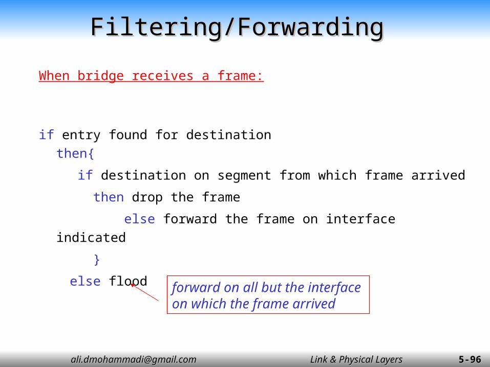
When bridge receives a frame:
if entry found for destinationthen{
if destination on segment from which frame arrived
then drop the frame
else forward the frame on interface indicated
}
else flood
forward on all but the interface on which the frame arrived

[email protected]@gmail.com Link & Physical LayersLink & Physical Layers 5-5-9797
Bridge ExampleBridge Example
Suppose C sends frame to D and D replies back with frame to C.
Bridge receives frame from from C notes in bridge table that C is on interface 1 because D is not in table, bridge sends frame into
interfaces 2 and 3 Frame received by D

[email protected]@gmail.com Link & Physical LayersLink & Physical Layers 5-5-9898
Bridge Learning: Example’Bridge Learning: Example’
D generates frame for C, sends Bridge receives frame
Notes in bridge table that D is on interface 2 Bridge knows C is on interface 1, so selectively forwards
frame to interface 1 Bridge adds D on interface 2 of the table.

[email protected]@gmail.com Link & Physical LayersLink & Physical Layers 5-5-9999
Interconnection Without BackboneInterconnection Without Backbone
Not recommended for two reasons:- Single point of failure at Computer Science hub- All traffic between EE and SE must path over CS segment
[email protected]@gmail.com Link & Physical LayersLink & Physical Layers 5-5-100100
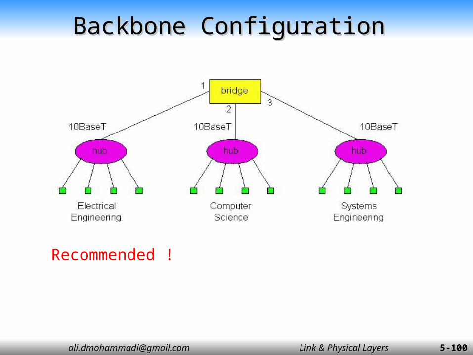
Backbone ConfigurationBackbone Configuration
Recommended !
[email protected]@gmail.com Link & Physical LayersLink & Physical Layers 5-5-101101
Bridges Spanning TreeBridges Spanning Tree
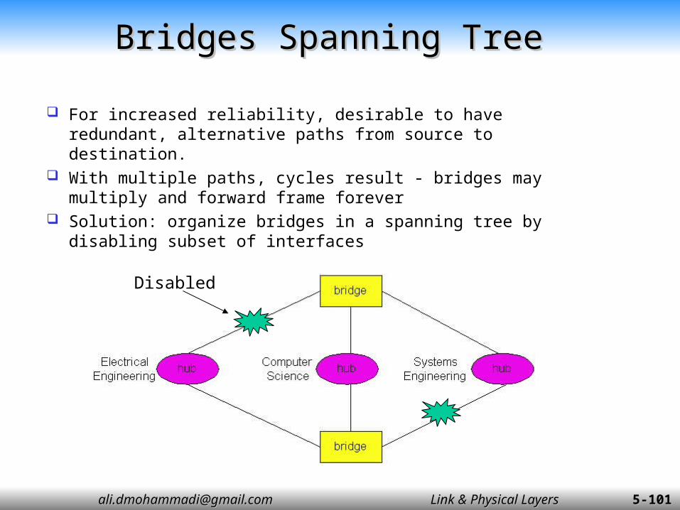
For increased reliability, desirable to have redundant, alternative paths from source to destination.
With multiple paths, cycles result - bridges may multiply and forward frame forever
Solution: organize bridges in a spanning tree by disabling subset of interfaces
Disabled
[email protected]@gmail.com Link & Physical LayersLink & Physical Layers 5-5-102102
Some Bridge FeaturesSome Bridge Features
Isolates collision domains resulting in higher total max throughput
Limitless number of nodes and geographical coverage
Can connect different Ethernet types Transparent (“plug-and-play”): no
configuration necessary

[email protected]@gmail.com Link & Physical LayersLink & Physical Layers 5-5-103103
Bridges vs. RoutersBridges vs. Routers
Both store-and-forward devices routers: network layer devices (examine network layer headers) bridges are link layer devices
Routers maintain routing tables, implement routing algorithms Bridges maintain bridge tables, implement filtering, learning
and spanning tree algorithms

[email protected]@gmail.com Link & Physical LayersLink & Physical Layers 5-5-106106
Ethernet SwitchesEthernet Switches
Essentially a multi-interface bridge
Layer 2 (frame) forwarding, filtering using LAN addresses
Switching: A-to-A’ and B-to-B’ simultaneously, no collisions
Large number of interfaces Often: individual hosts, star-
connected into switch Ethernet, but no collisions!
[email protected]@gmail.com Link & Physical LayersLink & Physical Layers 5-5-107107
Ethernet Switches’Ethernet Switches’
Cut-through switching: frame forwarded from input to output port without awaiting for assembly of entire frame slight reduction in latency
Combinations of shared/dedicated, 10/100/1000 Mbps interfaces

[email protected]@gmail.com Link & Physical LayersLink & Physical Layers 5-5-108108
Typical LAN (IP network)Typical LAN (IP network)
Dedicated
Shared

[email protected]@gmail.com Link & Physical LayersLink & Physical Layers 5-5-109109
hubs
bridges routers switches
Traffic isolation no yes yes yes
plug & play yes yes no yes
Optimal routing
no no yes no
Cut through yes no no yes
Summary comparisonSummary comparison

[email protected]@gmail.com Link & Physical LayersLink & Physical Layers 5-5-110110
Chapter 5 outlineChapter 5 outline
5.1 Introduction and services5.2 Error detection and correction 5.3 Links and Access Protocols5.4 Ethernet5.5 Ethernet Model5.6 Ethernet Frame Structure5.7 LAN addresses and ARP5.8 Ethernet Technologies5.9 Hubs, bridges, and switches5.10 Point to Point Protocol

[email protected]@gmail.com Link & Physical LayersLink & Physical Layers 5-5-111111
Point to Point Link Layer ControlPoint to Point Link Layer Control
One sender, one receiver, one link: easier than broadcast link: no Media Access Control no need for explicit MAC addressing e.g., dialup link, DHL connection, ISDN line
Popular point-to-point LLC protocols: PPP (point-to-point protocol) HDLC: High level data link control (Data link used to
be considered “high layer” in protocol stack!)

[email protected]@gmail.com Link & Physical LayersLink & Physical Layers 5-5-112112
PPP Design Requirements [RFC 1557]PPP Design Requirements [RFC 1557]
Packet framing: encapsulation of network-layer datagram in data link frame. carry network layer data of any network layer
protocol (not just IP) at same time. ability to de-multiplex upwards.
Bit transparency: must carry any bit pattern in the data field.
Error detection (no correction). Connection live-ness: detect, signal link failure to
network layer. Network layer address negotiation: endpoint can
learn/configure each other’s network address.

[email protected]@gmail.com Link & Physical LayersLink & Physical Layers 5-5-113113
PPP non-requirementsPPP non-requirements
no error correction/recovery no flow control out of order delivery OK no need to support multipoint links (e.g., polling)
Error recovery, flow control, data re-ordering all relegated to higher layers!

[email protected]@gmail.com Link & Physical LayersLink & Physical Layers 5-5-114114
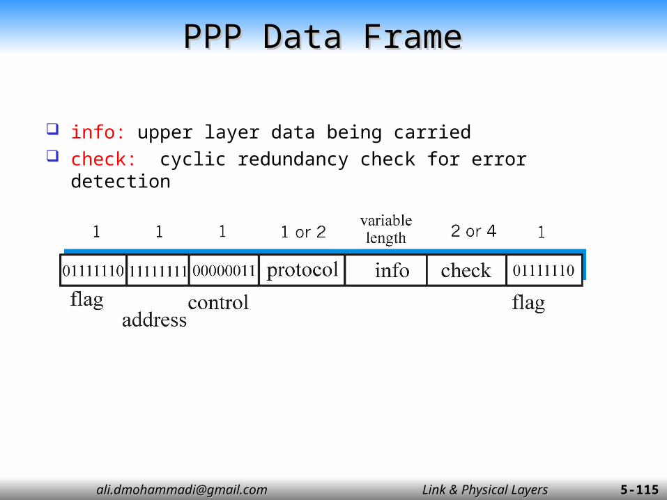
PPP Data FramePPP Data Frame
Flag: delimiter (framing) Address: does nothing (only one option) Control: does nothing; in the future possible multiple
control fields Protocol: upper layer protocol to which frame delivered
(eg, PPP-LCP, IP, IPCP, etc)
[email protected]@gmail.com Link & Physical LayersLink & Physical Layers 5-5-115115
PPP Data FramePPP Data Frame
info: upper layer data being carried check: cyclic redundancy check for error detection

[email protected]@gmail.com Link & Physical LayersLink & Physical Layers 5-5-116116
Byte StuffingByte Stuffing
“data transparency” requirement: data field must be allowed to include flag pattern <01111110> Q: is received <01111110> data or flag?
Sender: adds (“stuffs”) extra < 01111110> byte after each < 01111110> data byte
Receiver: two 01111110 bytes in a row: discard first byte,
continue data reception single 01111110: flag byte