Resource Center © ANIMA / Invest in Med - April 2011 Pierre Henry Samir Abdelkrim.
Malaysian Journal of Civil Engineering 26(3):397-413 (2014)
All rights reserved. No part of contents of this paper may be reproduced or transmitted in any form or by any means
without the written permission of Faculty of Civil Engineering, Universiti Teknologi Malaysia
CRACKING RESPONSE OF CONCRETE GRAVITY DAMS UNDER
SEISMIC LOADING
Ali Zine1* & Abdelkrim Kadid
2
1 Department of Hydraulics, University of Batna, Algeria
2Department of Civil Engineering, University of Batna, Algeria
1, 2Laboratoire de Recherche en Hydraulique Appliqué (LRHYA), University of Batna, Algeria
*Corresponding Author: [email protected]
Abstract: In this paper are presented the results obtained from a nonlinear seismic analysis of
concrete gravity dams. Three dams with different heights will be studied under the effect of
several earthquake ground motions. The fluid-structure interaction will be considered using the
added mass concept of Westergraad is used to simulate the fluid-structure interaction with the
foundation assumed to be rigid. The smeared cracking approach is used to model the initiation
and propagation of cracks through the dams. The response of the dam is characterized by
evaluating modal characteristics, displacements and crack patterns. The results obtained will
allow having an insight into the expected behavior of concrete dams under future expected
earthquakes and indicate that dynamic characteristics of a dam and the frequency content of the
ground motions are a couple of the key parameters to consider when assessing the seismic safety
of concrete gravity dams.
Keywords: Gravity dams, concrete, dynamic analysis, fluid-structure interaction, smeared
cracking model.
1.0 Introduction
Concrete gravity dams can be considered as vital infrastructures and play an important
role in the inland waterway transportation systems. Since many of them are built in high
seismicity area and have been operating for a long period of time, their performance
under strong ground motions is a subject of public concern and research attention.
Despite the fact that the seismic response of such massive structures has been the subject
of extensive studies over the past decades, there are still issues that have not been
investigated and fully understood. Although linear response structures allow having an
insight into the behavior of concrete gravity dams under earthquakes, it is evident that a
rigorous estimate of the seismic performance of a dam can be assessed only by a
nonlinear analysis. Due to the low tensile strength of concrete, concrete is likely to
experience cracking which can be either minor of severe. In case of minor cracking,
there is no substantial effect on the global stiffness of a dam. However for cases of
398 Malaysian Journal of Civil Engineering 26(3):397-413 (2014)
severe cracks, the dynamic behavior is totally different from that of a linear response
and must recourse to a nonlinear analysis. Cracking can be caused by several factors
such as construction, alkali-aggregate reactions, and loading. Cracking in concrete dam
body can be considered as one of the major type of damage models to concrete gravity
dams during strong earthquakes. In numerical analysis, the discrete and the smeared
crack models are considered major tools to consider the initiation and propagation of
cracks thorough the dam body. The discrete approach uses fracture mechanics concepts
to model discrete cracking observed. On one hand, this approach is potentially attractive
since it allows the accurate determination of the geometry of each crack. But on the
other hand, is has the disadvantage of requiring remeshing of the domain as the crack
surface changes which is complex and computationally expensive. The smeared
cracking model uses continuum models. It consists of modifying the constitutive law
governing the behavior of concrete.
The nonlinear dynamic behavior of concrete gravity dams has been the subject of many
studies. Pal (1976) studied the seismic response of Koyna dam using a smeared crack
model to model the initiation and growth of cracking. Mlakar (1987) studied the
nonlinear seismic response of three different gravity dam sections. The dam sections
with different heights were selected to be representative of the most common designs. A
linear constitutive model in compression and tension, coupled with the smeared crack
approach were adopted. The hydrodynamic effects were approximated using
Westergaard’s assumption through lumped masses distributed along the upstream face.
The numerical results obtained indicated that the examples sections completely cracked
across the width, with most of the cracking initiating at the upstream edge of the base
and at the locations of abrupt slope change along the downstream face. El-Aidi and Hall
(1989a, 1989b) used the smeared cracking model with a strength criterion for crack
detection. They performed parametric studies to assess the effects of initial conditions
induced by severe winter temperature and the effects of hydrodynamic and foundation
interaction mechanism on the nonlinear seismic behavior of the dam. Vergas-loli and
Fenves (1989) carried out a nonlinear seismic analysis of a gravity dam considering the
tensile cracking of concrete and the interaction between the dam and the compressible
water. The results obtained from this study indicate that concrete cracking is an
important nonlinear phenomenon and extensive cracking due to strong earthquakes may
affect the stability of the dams. Bhattacharjee and Leger (1995) used a rotating smeared
crack finite element model based on energy conservation principle to predict the static
fracture behavior of concrete gravity dam water penetration. Mao and Taylor (1997)
studied the nonlinear dynamic response of concrete gravity dams. They indicated that
the choice of a reliable concrete constitutive model and constitutive parameters to
predict the performance of concrete gravity dams under earthquakes is a challenging
task. The response of a typical medium height dam is examined suing ADINA package.
Yamaguchi et al. (2004) indicated that rigorous evaluation of the performance of typical
concrete gravity dam subjected to strong ground motions requires accurate modeling of
the nonlinear characteristics associated with the tensile behavior of the mass concrete.
Malaysian Journal of Civil Engineering 26(3):397-413 (2014)
399
Thus nonlinear time history analysis is required to directly estimate the severity and
extension of damage that could be expected. The results obtained showed that nonlinear
procedures can identify the ultimate capacity of existing concrete gravity dam taking
into account the most critical phenomena controlling the response and that the influence
of input parameters and ground motions of the nonlinear dynamic response should be
investigated by sensitivity analysis. Cai et al. (2008) developed a smeared crack model
bases on nonlinear fracture mechanics. They then carried out a mesh objectivity
verification study that showed that the proposed crack modeling method is mesh
objective. A benchmark dam and an existing dam were analyzed numerically.
Sensitivity study on the material fracture properties and fracture parameters was used to
investigate the uncertainties often encountered in this type of analysis. Mansouri et al.
(2011) have studied using the finite element method in the seismic fracture behavior of a
concrete gravity dam. The Bazant model which is based on nonlinear fracture was used
as a criterion to measure the growth of cracking and the smeared cracking model was
chosen to develop crack profiles. The results obtained provide profiles of growth of
expansion with and without the effects of reservoir.
2.0 Finite Elements Models
2.1 Structural Geometry
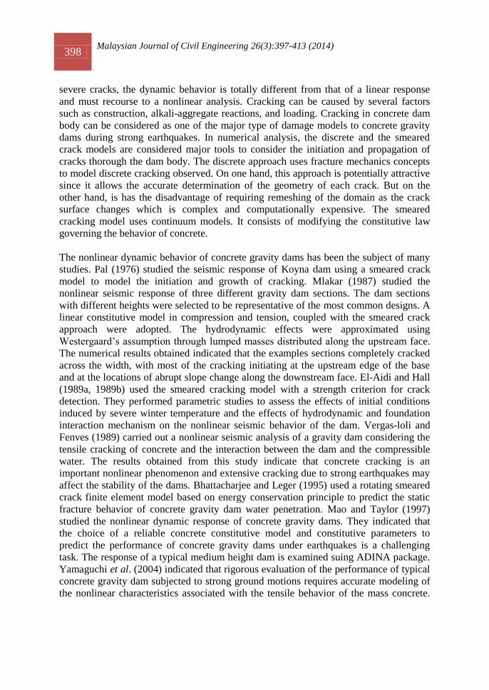
The structural geometries of the three concrete dams used in this study are shown in
figure 1. The first dam is 36.30 m high with a base of 25.77 m. The second one is 60 m
high with a base of 45.50 m. The last one has a height of 100 m with a base of 90 m.
Dam A Dam B Dam C
Figure 1: Geometry and dimensions of the dams

400 Malaysian Journal of Civil Engineering 26(3):397-413 (2014)
2.2 Finite Element Mesh
The models of dam A, B, and C consist of 280, 450, and 880 four nodded quadrilateral
isoparametric plane strain elements respectively, see figure 2.
Dam A Dam B Dam C
Figure 2: Finite element models of the dams
2.3 Material Modeling
It is well accepted that concrete is a very complex material. In this study, the concrete
model implemented in ADINA (2013) has been adopted. Three features are necessary to
realistically describe the material behavior:
- a stress-strain relation to include the high concrete nonlinearity.
- a failure surface that define tensile and compressive failure.
- a suitable technique to implement the post-cracking and crushing behavior.
In figure 3 is shown the compressive stress-strain relation for uniaxial and multiaxial
stress conditions. Different curve parameters are considered depending on whether the
material is in loading or unloading conditions.
The material assumed orthotropic with respect to the principal stress directions. If
cracking occurs in any direction, that direction is fixed from that point onward in the
computations. The Poisson ratio is assumed to be constant under tensile stresses and
variable in the compressive region to allow capturing the dilatancy.
The failure envelopes, based on principal stresses, are shown in figures 4 and 5.

Malaysian Journal of Civil Engineering 26(3):397-413 (2014)
401
Figure 3: Compressive stress-strain behaviors
Figure 4: Tensile failure envelope

402 Malaysian Journal of Civil Engineering 26(3):397-413 (2014)
Figure 5: Triaxial compressive failure envelope
After cracking, it is assumed that a failure plane develops perpendicular to the
corresponding principal stress direction. Thus, the normal and shear stresses across the
failure plane are reduced and plane stress conditions are assumed. Thus, the normal and
shear stiffness's across the failure plane are reduced and plane stress conditions are
assumed. These stiffness's reductions are considered by using two constants following
the shear retention factor concept. Typically, = 0.0001and = 0.5. The factor is
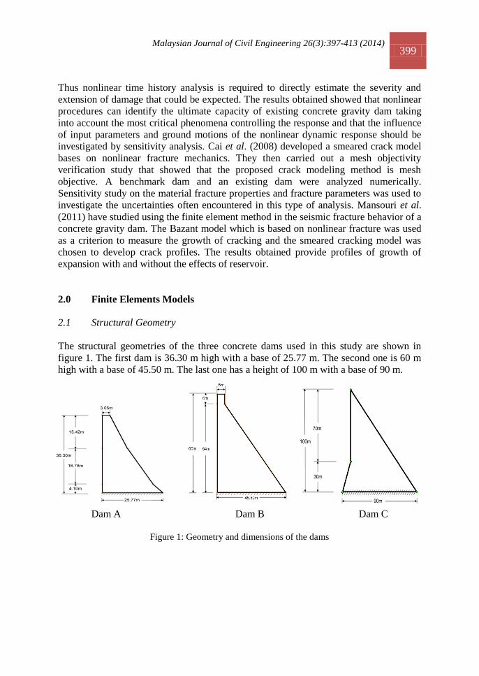
not exactly equal to zero in order to avoid the possibility of a singular stiffness. Figure 7
shows the material behavior in the direction normal to the tensile failure plane. ξ
is a user defined variable which determines the amount of tension stiffening. To obtain a
mesh independent solution, the fracture energy can be directly provided and
therefore, ξ is evaluated at each integration point based on the finite element size, figure
7.
Figure 6: Uniaxial tensile behavior
Malaysian Journal of Civil Engineering 26(3):397-413 (2014)
403
Figure 7: Parameter ξ calculation
ξ=
with energy released per unit area in direction perpendicular to direction
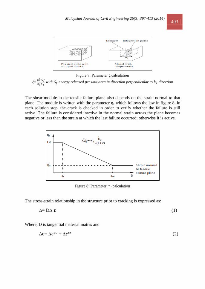
The shear module in the tensile failure plane also depends on the strain normal to that
plane: The module is written with the parameter which follows the law in figure 8. In
each solution step, the crack is checked in order to verify whether the failure is still
active. The failure is considered inactive in the normal strain across the plane becomes
negative or less than the strain at which the last failure occurred; otherwise it is active.
Figure 8: Parameter calculation
The stress-strain relationship in the structure prior to cracking is expressed as:
∆= D∆ 𝛆 (1)
Where, D is tangential material matrix and
∆𝛆= ∆ + ∆ (2)
404 Malaysian Journal of Civil Engineering 26(3):397-413 (2014)
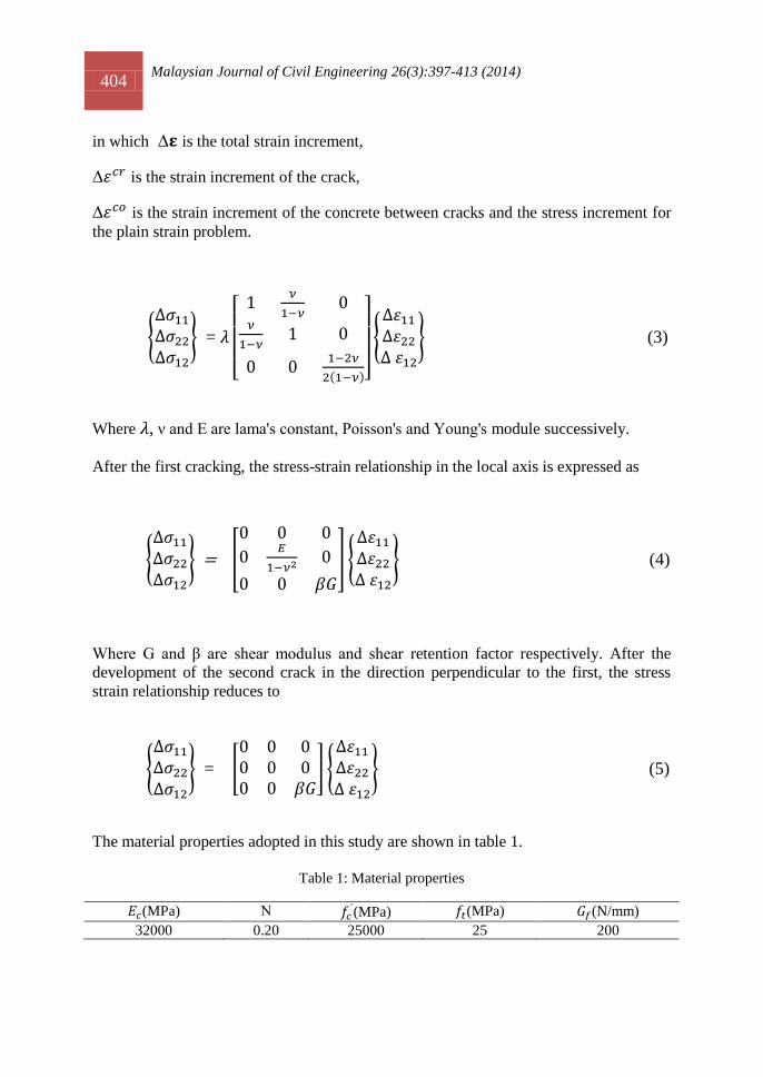
in which ∆𝛆 is the total strain increment,
∆ is the strain increment of the crack,
∆ is the strain increment of the concrete between cracks and the stress increment for
the plain strain problem.
{
} =
[
( )]
{
} (3)
Where , ν and E are lama's constant, Poisson's and Young's module successively.
After the first cracking, the stress-strain relationship in the local axis is expressed as
{
} = [
] {
} (4)
Where G and β are shear modulus and shear retention factor respectively. After the
development of the second crack in the direction perpendicular to the first, the stress
strain relationship reduces to
{
} = [
] {
} (5)
The material properties adopted in this study are shown in table 1.
Table 1: Material properties
(MPa) Ν (MPa) (MPa) (N/mm)
32000 0.20 25000 25 200
Malaysian Journal of Civil Engineering 26(3):397-413 (2014)
405
Where is the Young’s modulus, ν is the Poisson’s ratio, is the maximum uniaxial
compressive strength, is the maximum uniaxial tensile strength and is the fracture
energy.
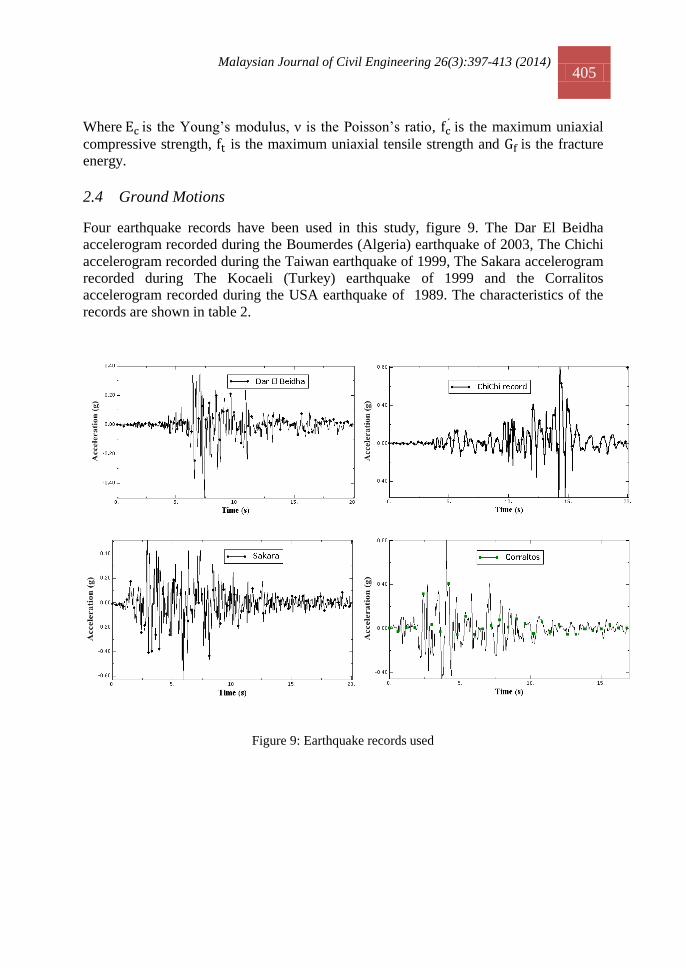
2.4 Ground Motions
Four earthquake records have been used in this study, figure 9. The Dar El Beidha
accelerogram recorded during the Boumerdes (Algeria) earthquake of 2003, The Chichi
accelerogram recorded during the Taiwan earthquake of 1999, The Sakara accelerogram
recorded during The Kocaeli (Turkey) earthquake of 1999 and the Corralitos
accelerogram recorded during the USA earthquake of 1989. The characteristics of the
records are shown in table 2.
Figure 9: Earthquake records used
406 Malaysian Journal of Civil Engineering 26(3):397-413 (2014)
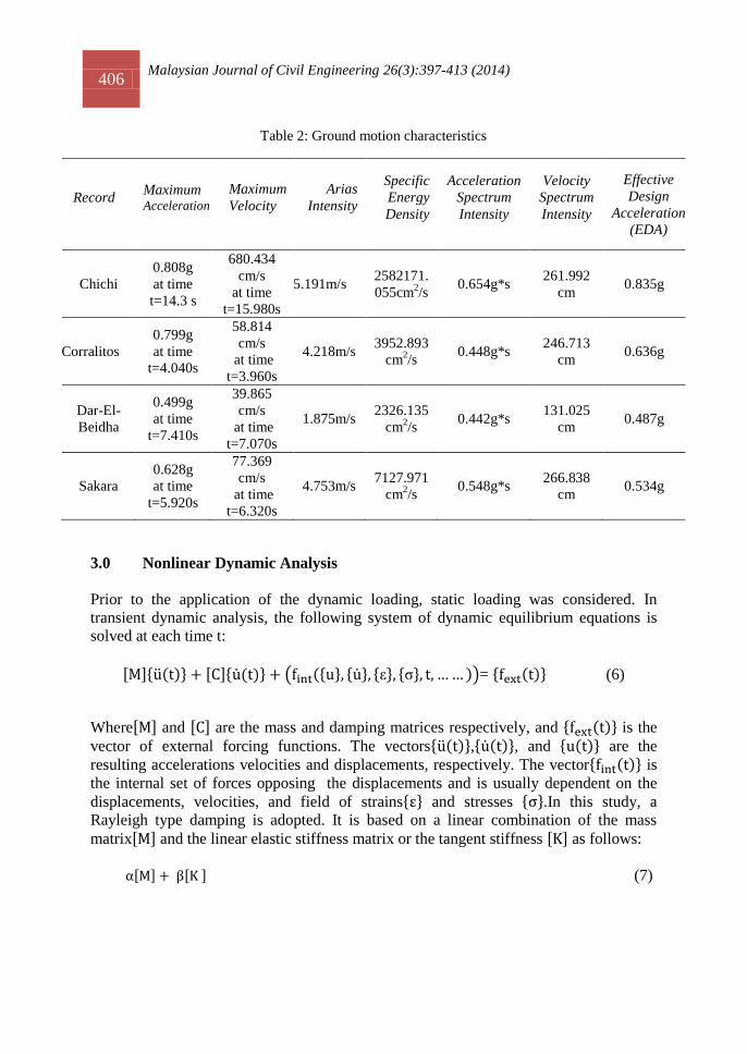
Table 2: Ground motion characteristics
Record Maximum Acceleration
Maximum
Velocity
Arias
Intensity
Specific
Energy
Density
Acceleration
Spectrum
Intensity
Velocity
Spectrum
Intensity
Effective
Design
Acceleration
(EDA)
Chichi
0.808g
at time
t=14.3 s
680.434
cm/s
at time
t=15.980s
55.191m/s 2582171.
055cm2/s
0.654g*s 261.992
cm 0.835g
CCorralitos
0.799g
at time
t=4.040s
58.814
cm/s
at time
t=3.960s
4.218m/s 3952.893
cm2/s
0.448g*s 246.713
cm 0.636g
Dar-El-
Beidha
0.499g
at time
t=7.410s
39.865
cm/s
at time
t=7.070s
1.875m/s 2326.135
cm2/s
0.442g*s 131.025
cm 0.487g
Sakara
0.628g
at time
t=5.920s
77.369
cm/s
at time
t=6.320s
4.753m/s 7127.971
cm2/s
0.548g*s 266.838
cm 0.534g
3.0 Nonlinear Dynamic Analysis
Prior to the application of the dynamic loading, static loading was considered. In
transient dynamic analysis, the following system of dynamic equilibrium equations is
solved at each time t:
, -* ( )+ , -* ( )+ ( (* + * + * + * + ))= * ( )+ (6)
Where, - and , - are the mass and damping matrices respectively, and * ( )+ is the
vector of external forcing functions. The vectors* ( )+,* ( )+, and * ( )+ are the
resulting accelerations velocities and displacements, respectively. The vector* ( )+ is
the internal set of forces opposing the displacements and is usually dependent on the
displacements, velocities, and field of strains* + and stresses * +.In this study, a
Rayleigh type damping is adopted. It is based on a linear combination of the mass
matrix, - and the linear elastic stiffness matrix or the tangent stiffness , - as follows:
, - , - (7)

Malaysian Journal of Civil Engineering 26(3):397-413 (2014)
407
Where the coefficients and are determined to provide for two selected damping
ratios for two specific modes of vibration, in the first two modes.
The direct integration of the above equations is required. One of the most widely used
methods is the Newmark method with automatic time stepping. For large number of
degrees of freedom, the numerical damping feature is essential to suppress undesirable
higher modes.
The hydrostatic load was applied as pressure loading on the upstream face of the dam.
The hydrodynamic loading of the reservoir was approximated by the Westergraad
method of added masses. Due to the fact that strength based criterion for crack analysis
of concrete structures can cause the results to be mesh sensitive, that is stresses become
progressively larger as the mesh around the crack tip is refined, the fracture mechanics
approach bases on energy principles has been adopted in this study, this is a rational
technique for analyzing the initiation and the growth of cracks in concrete structures.
4.0 Results and Discussion
4.1 Modal Results
The periods of the three dams are shown in table 3.
Table 3: Periods of the structures in seconds
Structures Mode 1 Mode 2 Mode 3
Dam A 0.1307 0.04983 0.04021
Dam B 0.1939 0.08312 0.06526
Dam C 0.2847 0.1293 0.1016
4.2 Cracking Profiles
The cracks patterns in dam A under the different earthquake records are shown in figure
10. For all the earthquake records, most of the cracking is concentrated on the
downstream face with a tendency to propagate towards the body of the dam. However,
the initiation of cracking at the base is largely dependent on the ground motion record
used. For this dam, the level of damage is relatively small.

408 Malaysian Journal of Civil Engineering 26(3):397-413 (2014)
Dar El Beidha record
t = 8.50 s t = 12.00 s t = 16.00 s
Corralitos record
t =4.44 s t =5.50 s t =10.20 s
Sakara record
t = 6.10 s t = 6.43 s t =6.70 s
Chichi record
t = 15.94 s t =6.08 s t = 16.00 s
Figure 10: Crack profiles for dam A

Malaysian Journal of Civil Engineering 26(3):397-413 (2014)
409
For dam B, cracking is more important than that of dam A, figure 11. The upstream face
can be cracked from the top to the base for the Chichi and Sakara records while for Dar
El Beidha and Corralitos records there are less cracks on the upstream face and near the
base. Again, the downstream face exhibits considerable cracking extending to the neck
at the location of slope change.
Dar El Beidha record
t = 7.77 s t = 7.90 s t = 16.00 s
Corralitos record
t = 6.00 s t = 8.10 s t = 16.00 s
Sakara record
t = 4.10 s t = 8.26 s t= 16.00 s
Chichi record
t = 15.10 s t = 15.40 s t = 16.00 s
Figure 11: Crack profiles for dam B

410 Malaysian Journal of Civil Engineering 26(3):397-413 (2014)
In dam C, figure 12, the cracks occurred on the downstream face, at the base and at the
location of slope change near the upstream face. For the Sakara and Corralitos records
the analysis terminated prematurely. The cracks on the downstream face coalesced with
those of the upstream face for the Dar El Beidha record for a time of 16 s. The influence
of the frequency content of the ground motions is evident as the crack patterns differ for
each record. The density of cracking is greater than that of dam A suggesting an
influence of the dynamic characteristics of the dams.
Dar El Beidha record
t = 6.00 s t = 7.80 s t = 8.10 s t = 16.00 s
Sakara record
t = 3.10 s t = 3.60 s t = 3.93 s
Chichi record
t = 6.00 s t= 15.00 s t=15.33s
Corralitos record
t=3.47s t = 3.65 s t = 3.80 s
Figure12: Crack profiles for dam C
Malaysian Journal of Civil Engineering 26(3):397-413 (2014)
411
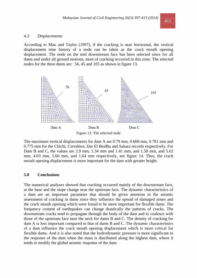
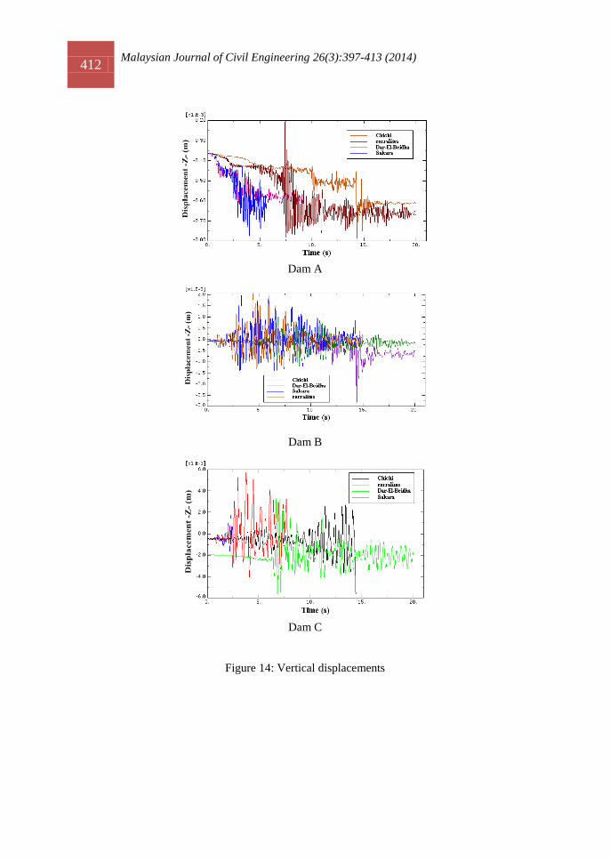
4.3 Displacements
According to Mao and Taylor (1997), if the cracking is near horizontal, the vertical
displacement time history of a node can be taken as the crack mouth opening
displacement. The node on the mid downstream face has been selected since for all
dams and under all ground motions, most of cracking occurred in this zone. The selected
nodes for the three dams are: 56, 45 and 105 as shown in figure 13.
Figure 13: Location of nodes where displacement are evaluate
Figure 13: The selected node
The maximum vertical displacements for dam A are 0.79 mm, 0.668 mm, 0.781 mm and
0.775 mm for the Chichi, Corralitos, Dar El Beidha and Sakara records respectively. For
Dam B and C, the values are 2.9 mm, 1.34 mm and 1.41 mm, and 1.58 mm, and 5.62
mm, 4.03 mm, 5.66 mm, and 1.64 mm respectively, see figure 14. Thus, the crack
mouth opening displacement is more important for the dam with greater height.
5.0 Conclusions
The numerical analyses showed that cracking occurred mainly of the downstream face,
at the base and the slope change near the upstream face. The dynamic characteristics of
a dam are an important parameter that should be given attention in the seismic
assessment of cracking in dams since they influence the spread of damaged zones and
the crack mouth opening which were found to be more important for flexible dams. The
frequency content of earthquakes can change drastically the patterns of cracks. The
downstream cracks tend to propagate through the body of the dam and to coalesce with
those of the upstream face near the neck for dams B and C. The density of cracking for
dam A is less important compared to that of dams B and C. The dynamic characteristics
of a dam influence the crack mouth opening displacement which is more critical for
flexible dams. And it is also noted that the hydrodynamic pressure is more significant to
the response of the dam when the mass is distributed along the highest dam, where it
tends to modify the global seismic response of the dam.
412 Malaysian Journal of Civil Engineering 26(3):397-413 (2014)
Dam A
Dam B
Dam C
Figure 14: Vertical displacements
Malaysian Journal of Civil Engineering 26(3):397-413 (2014)
413
References
ADINA, (2013). Version 8.2, Users Manuals. ADINA; R& D, Inc., Watertown, Massachusetts,
USA.
Bhattacharjee, S.S., and Leger, P. (1995). Fracture response of gravity dams due to rise of
reservoir elevation. Journal of Structural Engineering. September 1995. 1299-1305.
Cai, Q., Robberts, J.M., And Ransburg, B.W.J. (2008). Finite element fracture modeling of
concrete gravity dams. Journal of the South African Institution of Civil Engineering, 50:1,
13-24.
El-Aidi, B., and Hall, J.F. (1989a). Non-linear earthquake response of concrete gravity dams,
Part 1: Modeling, Earthquake Engineering and Structural Dynamics. 18, 837-851.
El-Aidi, B., and Hall, J.F. (1989b). Non-linear earthquake response of concrete gravity dams,
Part II: Behavior, Earthquake Engineering and Structural Dynamics. 18, 853-865.
Mansouri, A., Neshaei, M.A.L., and Aghajany. R. (2011). Fracture analysis of concrete gravity
dam under earthquake induced loads. Journal of Applied Sciences, Environment, and
Management.15 (2) 317-325
Mao, M. and Taylor, C.A. (1997). Nonlinear seismic cracking analysis of medium-height
concrete gravity dams. Computers and Structures. 64:5/6, 1197-1204.
Mlakar, P. (1987). Nonlinear response of concrete gravity dams to strong earthquake-induced
ground motions. Computers and Structures. 26:1,165-173.
Pal, N. (1976). Seismic cracking of concrete gravity dams. Journal of the Structural Division
(ASCE). 102:9, 1827-1844.
Vergas-loli, M. And Fenves, G.L. (1989). Effects of concrete cracking on the earthquake
response of gravity dams. Earthquake Engineering and Structural Dynamics. 18, 575-592.
Yamaguchi, Y., Hall, R., Sasaki, T., Matheu, E., Kanenawa, K., Chudgar, A., and Yule. D.
(2004). Seismic performance evaluation of concrete gravity dams. Proceedings of the 13th
World Conference on Earthquake Engineering –Vancouver, Canada.