Algorithms Management Systems Hot Deck/Cold …€¦ · ABSTRACT...
80
a 1 11 ob o 3 j,sMb tro | Algorithms for Building Management and Control Systems — Hot Deck/Cold Deck/Supply Air Reset, Day/Night Setback, Ventilation Purging, and Hot and Chilled Water Reset U.S. DEPARTMENT OF COMMERCE National Bureau of Standards National Engineering Laboratory Center for Building Technology Building Equipment Division Washington, DC 20234 March 1984 Sponsored by: Office of Buildings and Community Systems U.S. Department of Energy U.S. Navy Civil Engineering Laboratory U.S. Department of Defense ,U56 ! k%4 . | 34-23451 1334
-
Upload
truongquynh -
Category
Documents
-
view
213 -
download
0
Transcript of Algorithms Management Systems Hot Deck/Cold …€¦ · ABSTRACT...

a 1 1 1 ob o 3j,sMb tro | Algorithms for Building
Management and Control Systems —Hot Deck/Cold Deck/Supply Air Reset,
Day/Night Setback, Ventilation
Purging, and Hot and Chilled WaterReset
U.S. DEPARTMENT OF COMMERCENational Bureau of Standards
National Engineering Laboratory
Center for Building TechnologyBuilding Equipment Division
Washington, DC 20234
March 1984
Sponsored by:
Office of Buildings and Community SystemsU.S. Department of EnergyU.S. Navy Civil Engineering LaboratoryU.S. Department of Defense
,U56 ! k % 4. |
34-23451
1334


NATIONAL BUREAUOF STANDARDS
LIBRARY
NBSIR 84-2846
CONTROL ALGORITHMS FOR BUILDING
MANAGEMENT AND CONTROL SYSTEMS -
HOT DECK/COLD DECK/SUPPLY AIR RESET,
DAY/NIGHT SETBACK, VENTILATIONPURGING, AND HOT AND CHILLED WATERRESET
William B. May, Jr.
U S. DEPARTMENT OF COMMERCENational Bureau of Standards
National Engineering Laboratory
Center for Building Technology
Building Equipment Division
Washington, DC 20234
March 1984
Sponsored by:
Office of Buildings and Community SystemsU.S. Department of Energy
U.S. Navy Civil Engineering Laboratory
U.S. Department of Defense
U.S. DEPARTMENT OF COMMERCE, Malcolm Baldrige, Secretary
NATIONAL BUREAU OF STANDARDS, Ernest Ambler, Director


ABSTRACT
Software is an important component of building management and controlsystems (BMCS). This report describes concepts, algorithms, and software usedin BMCS components developed in the NBS building systems and controlslaboratory. The basic concepts, considerations and general algorithms forhot deck/cold deck supply air setpoint reset, day/night thermostat andventilation setback, ventilation purging, and hot/chilled water supplysetpoint reset are presented. Reset is the changing of a setpoint on a
Heating, Ventilating and Air Conditioning (HVAC) system controlled by a
feedback controller to match the system output to the system load. Setback is
the changing of HVAC system operation to reduce energy use during unoccupiedperiods. Purging is the use of outdoor air during unoccupied periods to reducemechanical conditioning requirements. Specific implementations of thealgorithms in software on an actual BMCS are presented as examples.
KEY WORDS: air handling unit control; building (energy) management and controlsystems (EMCS.BMCS); chilled water reset; computer control; controlalgorithms; control software; day/night setback; energy management; hot waterreset; heating, ventilating and air conditioning (HVAC); outside air reset;supply air setpoint reset; ventilation purging.
iii


TABLE OF CONTENTSPage
1 . INTRODUCTION .. 1
2. THE AIR HANDLING UNIT AND BUILDING ZONE SYSTEM 2
3. SUPPLY AIR SETPOINT RESET CONTROL 5
3.1 Reset Algorithm for Single Path Systems Based on OutsideAir Temperature 5
3.2 Reset Algorithm for Dual Path Systems Based on Outside AirTemperature 11
3.3 Setpoint Reset Algorithms based on Zone Requirements 12
4. DAY/NIGHT SETBACK 20
4.1 Local Space Equipment 204.2 Space Temperature and Ventilation Setback 22
4.3 Day/Night Setback Actions 23
4.4 Basic Setback Algorithm. 25
5. VENTILATION PURGING 27
5.1 Basic Concepts.... 27
5.2 Basic Algorithm for Ventilation Purge Control 305.3 Ventilation Purging Algorithm Components 30
5.4 Ventilation Purge Algorithm Timing. 35
6. HOT WATER AND CHILLED WATER SUPPLY TEMPERATURE RESET 36
6.1 Outside Air Temperature Supply Water Reset 366.2 Demand Supply Water Temperature Reset 36
6.3 Possible Demand Supply Water Reset Load Determination Algorithm.. 386.4 Hot Water Reset Setpoint Selection Algorithm.... 406.5 Chilled Water Reset Setpoint Selection Algorithm 42
7. EXAMPLES OF ACTUAL CONTROL ALGORITHMS 43
7.1 Example Field Interface Device Software Architecture 43
7.2 Basic Air Handling Unit Control Task 457.3 Example Outside Air Supply Air Reset Algorithm 46
7.4 Example Zone Demand Supply Air Reset Algorithm.. 487.5 Example of Day/Night Setback Algorithms 51
7.6 Example Ventilation Purging Algorithm 52
8. CONCLUSIONS 56
9. REFERENCES 57
APPENDIX A - Outside Air Supply Air Reset Control Routines 58
APPENDIX B - Zone Demand Supply Air Reset Control Routines forConstant Volume Reheat System 60
APPENDIX C - Day/Night Setback Control Routines 6 2
APPENDIX D - Ventilation Purging Control Routines 6 5
v

1
2
3
4
5
6
7
8
9
10
11
12
13
14
15
16
2
6
7
8
9
10
12
13
16
18
26
26
29
31
32
LIST OF FIGURES
Dual duct air handling unit and multiple zone system
Steady-state room temperature versus outside airtemperature for various supply air temperatures
Required supply air setpoint temperatures versus outside airtemperature for winter and summer room temperatures
Supply air temperature versus outside air temperature for twoextreme zones served by an air handling unit
Supply air temperature versus outside air temperature for an anair handling unit....'
Outside air reset algorithm for supply air temperature setpointin single path (deck) air handling systems
Supply air temperature versus outside air temperature for twodecks of a dual path system before application of limits
Block diagram of feedback system for supply air reset based on
zone requirements
Generalized zone heating equipment output versus supply airsetpoint for a given room condition
Supply air temperature setpoint reset algorithm using feedbackfrom measurement of local zone conditioning requirements
Algorithm for day/night setback from normal to setback state....
Day/night setback algorithm for return to normal state fromsetback.
Space, supply and outside air temperatures during an unoccupiedperiod with ventilation purging
Basic ventilation purging algorithm
Algorithm to determine if the building space requires coolingfor the ventilation purging algorithm
Algorithm to determine if outside air can provide cooling usedfor the ventilation purging algorithm
vi

17 Algorithm to determine current load of air handling unit coil
for supply water reset 39
18 Algorithm to select supply water setpoint temperature forsupply water reset 41
19 Example of outside air supply air reset schedule specified by
three points 48
LIST OF TABLES
Number Page
1 Supply air reset criteria for various system types 15
2 Space zone thermostat types 21
3 Possible information transmitted between parts of a supply waterreset algorithm 37
4 NBS FID task table 44
5 NBS FID outside air supply air reset parameter table 47
6 NBS FID zone demand supply air reset parameter table 50
7 Parameters used by the ventilation purging algorithm 54
vii


1. INTRODUCTION
A computer-based building management and control system (BMCS) relies heavilyon computer software to utilize efficiently the heating, ventilating, and air
conditioning (HVAC) equipment in the building. HVAC control software is
available in proprietary or system dependent packages, usually supplied with a
BMCS system supplied by a particular vendor. However, if listings of thesoftware source are not supplied, the BMCS owner or HVAC designer will notknow if the BMCS system can meet the HVAC design specifications. Even if the
control algorithms used are known, there is only a small amount of HVACcontrol algorithm software in the public domain to use for baseline comparisonpurposes. This report describes basic concepts and non-proprietary algorithmsused in control software that was developed at the National Bureau of
Standards (NBS) for use in the NBS building management and controlslaboratory
.
BMCS control strategies fall into at least two categories. Direct control (or
Direct Digital Control, DDC) refers to strategies and algorithms that controlthe building equipment directly without the use of conventional pneumatic or
electronic local analog control, implementing lower level functions such as
closed loop control of valves, dampers, and actuators. Supervisory ormanagement strategies control the building in a broader sense, managingequipment systems by methods such as selecting setpoints, and choosing optimumoperating times as a function of variables including electrical demand, time,weather conditions, occupancy, and heating and cooling requirements.
The many functions of modern building management and control systems areusually distributed among a number of computer processors. Control algorithmsare usually intended for operation at a particular level of the system. For a
large BMCS, the tri-services specification [1] defines four levels in a
hierarchy. These are the central level (CCU), the communication controllerlevel (CCC), the distributed control level (FID), and the data gathering andconditioning level(MUX). The distributed control level is occupied byequipment given the name FID for field interface device, or RPU for remoteprocessing unit. It is at this level that the software described in thisreport is intended to operate.
This report discusses several types of supervisory control strategies. Theseare day/night thermostat and ventilation setback, ventilation purging, hot orchilled water supply temperature setpoint reset, multizone/dual duct hotdeck/cold deck setpoint reset, and reheat/VAV supply air reset. These are allstrategies that may be applied to control of air handling units servingbuilding core or perimeter spaces in commercial or industrial buildings.Algorithms for these strategies are discussed in several chapters of thusreport, and actual algorithms and software developed for the NBS controlslaboratory BMCS system are presented in a separate chapter.
1

2. THE AIR HANDLING UNIT AND BUILDING ZONE SYSTEM
The strategies discussed in this report are primarily intended for control of
HVAC systems that utilize central air handling units to supply ventilationand/or conditioned air to the spaces in a building. Although day/nightsetback is applicable in any type of building, and supply water reset is
applicable to any building with central boilers or chillers, all controlstrategies are discussed in the context of a building with one or more centralair handling units.
An air handling unit can be one of several different types. The types of
units currently in use will be described to define the terminology used inthis report. One type of unit, the dual duct system, is shown in Figure 1
with much of the detail of an actual air handler omitted. Two ducts allow airto enter the unit, one carrying return air from the building spaces, the otherbringing in outside air for ventilation or ’free” conditioning. Damperscontrol the relative amounts of each air source. The dual duct unit has twopaths or "decks" containing heat exchangers, and two supply ducts leading fromthe air handler to one or more building zones. The heat exchangers in eachdeck are either for heating or cooling, and a preheat coil used to avoidfreezing of the other coils is shown just after the return-outside air mixingarea. The cooling coils might be chilled water coils, refrigerant or directexpansion (DX) coils, or air washers. The heating coils could be steam or hotwater heat exchangers. Two coils may be used in each deck to allow optionalhumidity control by overcooling to produce condensation, and reheating. Inactual installations there may be more, fewer, or none of these coils in a
deck. The upper deck is called the "hot deck", and is intended to producewarm air for the building spaces. The lower deck is called the "cold deck"and is intended to provide cool air. In a dual duct system air from hot andcold decks is sent through separate ducts to building spaces and is mixed at
the space to maintain a desired room temperature.
Damper Return air fan
Relief ^air ^
Return air
figure 1. dual duct air handling unit and multiple zone system
2

The dual duct air handler design can be converted to other types of air
handlers by omitting one of the supply ducts or one of the decks. If themixing for each zone is performed at the air handling unit and the mixed air
is transported to each zone in a single duct* the system becomes a multizonesystem. If the cold deck is eliminated, so that only a single deck with a
supply fan is used, this would represent a single or multiple zone constantvolume system, or, if the fans and zone supply boxes could vary the volume of
air delivered to the zones, this configuration would be a variable air volumesystem (VAV). If reheat coils were added to the individual zones, the systemwould be a reheat system, either VAV or constant volume. Completedescriptions of system types are available in the ASHRAE handbook [2].
In the central air handler and multiple building zone system, there are twoimportant types of control or process variables which must be maintained at
desired values. The first of these is the space temperature (and humidity) in
the zones. The other variable is the temperature (and humidity) of the airstream or streams leaving the air handling unit. For a dual deck system,there is a cold deck setpoint temperature and a hot deck setpoint. Forsystems with a single deck such as reheat, single zone, or single deck VAV,there is a single supply air temperature.
The primary criterion for selection of the zone temperature setpoint is the
comfort of the building occupants, or if the building is not occupied, therequirements of materials or machines located in the building. The zonesetpoint is often not a single temperature/humidity but a range oftemperatures and humidities, within which the comfort level is consideredacceptable. This is the "zero energy band' concept which is useful forconserving energy when space loads swing from heating to cooling within a
relatively short time span [3]. If the space condition is floating within thecomfort band, no mechanical conditioning of the space is permitted.
The selection of supply air setpoint(s) is more complicated than the selectionof a space setpoint. If a single zone is being supplied by an air handler,the supply air setpoint is the temperature (and humidity) of the supply airwhich will allow the space temperature (and humidity) for that zone to bemaintained. This air condition is determined by the space heating or coolingrequirement and the air volume flow rate entering the zone. If two or morezones are being supplied, it is to be expected that the proper entering aircondition will vary among the zones. A building may be designed to have equalentering conditions for all zones, even though zone requirements differ, byadjusting the design air flow to each zone. The design air flow distributionis probably not ideal for all zone loading conditions, resulting in unequalentering air condition requirements at certain times. The supply air conditionmust then be chosen to allow the zone with the highest or lowest entering airtemperature and humidity requirement (depending on the specific system) to besatisfied, because otherwise some zones will not be able to maintain a
comfortable state.
The simplest control of supply air temperature is to use a constant hot deck,cold deck, or supply air temperature so that all zones are satisfied for allreasonable load conditions. For dual deck systems, mixing of hot and cold airstreams, and for reheat systems, reheating of cool air at the zone, will allowany zone to be supplied with air at the proper temperature. However, when air
3

is cooled and reheated, this uses more energy than if the air had simply been
cooled or heated to the correct tempeature for a zone. Therefore it is
important to select the proper supply air temperatures to minimize energywaste
.
The least complex control system for a central air handler and zone systemuses independent feedback control loops to maintain each zone temperature (by
reheat coil control, or mixing damper control), and an independent system to
maintain supply air temperatures. In this case the zone and supply aircontrols are loosely coupled, since neither control loop is connected to theother. An example of this is a system with "outside air reset" control ofsupply air temperature. The selection of supply air setpoints is based on theoutside air temperature, not the actual space conditions. With tightlycoupled controls, the system controlling supply air temperatures takes intoaccount the actual conditions in the space zones. An example of this is theselection of supply air setpoints based on actual measurement of individualzone loads.
Two of the strategies discussed in this report control the setpoints for the
zone and supply air temperatures. Day/Night thermostat setback changes thezone setpoints. Hot deck/cold deck/supply air reset changes the supply airsetpoints. The other strategies discussed in the report are concerned withtwo other types of process or control variables. These are the ventilationair rate and the hot or chilled water supply temperatures for heat exchangercoils. Day/night ventilation setback changes the setpoint for minimumventilation air rate. Hot water/chilled water reset changes the setpoint forthe hot or chilled water supplied to the coils in the air handling unit. Theremaining strategy, ventilation purging, makes a temporary change in theventilation air setpoint to improve building operation economy.
4

3. SUPPLY AIR SETPOINT RESET CONTROL
Throughout this chapter, supply air setpoint will be assumed to be either a
dry bulb temperature setpoint, or a combination of dry bulb and humidity (wet
bulb) setpoints. If only the dry bulb temperature is controlled, undercertain conditions the space humidity may approach an unacceptable state if
the dry bulb setpoint is reset to a high value during cooling operation. If
this is possible, it is desirable to have a humidity override included in a
setpoint reset algorithm. A humidity override would use data from one or morehumidity or wet bulb temperature sensors in the supply air stream or thebuilding zones. If the humidity level became unacceptable, further reset of
the supply air temperature would be prevented.
Depending on the specific system, an air handling unit may have one or twosupply air conditions that must be maintained under closed loop control. In
simple VAV or reheat systems there will be one supply air condition which is
selected to match the space loading. For multizone or dual duct systems,there is a hot deck and a cold deck supply air setpoint. These must beselected both to match the space loading in the zones supplied, and tominimize the difference between the two supply conditions to avoid excessivereheating and recooling.
The use of fixed design setpoints for air supply temperatures is an easyapproach, but can result in energy loss through reheating or recooling of air,
either by mixing of hot and cold deck air streams which are widely separatedin temperature, or by terminal reheat of excessively cold supply air. Sinceconditions change throughout the year and even during the day, the energy lost
will vary with time.
Reset is defined as a method of changing the setpoint of a system tominimize system energy consumption by matching system output to the systemload. Reset control methods may be categorized by the means used to select a
setpoint temperature for different load conditions. Some control algorithmsmight use outdoor air temperature as a load indicator, while others mightdirectly or indirectly measure actual space heating and cooling requirements.
3.1 Reset Algorithm for Single Path Systems Based on Outside Air Temperature
The least complicated method of supply air reset is outside air temperaturereset. The basis of this method is the assumption that the heating or coolingrequirements of a zone can be considered a function of a single variable, theoutside air temperature. In reality, zone requirements are dependent on otherfactors such as solar gain, wind conditions which affect air infiltrationrates, internal heat generation rates, and latent heat loads. However, theoutside air reset method is not intended to exactly match supply air setpointsto system requirements. The reset schedule used is an estimate based oncalculations for the best setpoint temperature at various design conditionswhere solar gain, infiltration, and internal loads are specified in additionto outside air temperature. If the design conditions selected are an accurateestimate of the conditions encountered in actual operation, then the outsideair reset method will yield acceptable results, and savings over the use ot a
fixed setpoint.
5

If the infiltration, internal heat generation rates, and maximum solar gains
are relatively constant in a given zone from day to day, the required dry bulb
temperature for air entering the zone to maintain zone conditions can be
assumed to be approximately a linear function of outside air temperature. Thecurves in figure 2 were generated using a simple model of a zone with aninternal heat source, a gain or loss to the outside air, and a constant volumesupply air source with a variable room entering dry bulb temperature. Latentloads were not included. A more complicated zone model could be used to
generate more accurate curves.
figure 2. Steady-state room temperature versus outside air temperature forvarious supply air temperatures.
Figure 2 shows that for a fixed supply air temperature, the steady state roomtemperature will vary with outside temperature, as would be expected. Thecurves for different supply temperatures can be considered to be parallel,indicating that figure 2 can be described by:
Troom A * Toa + B * Tga + C. ( 1 )
where A,B, and C are constants, TQa is outside air temperature, and T ga is
supply air temperature. The value of the constants will change with thecharacteristics of the zone. If the zone were highly insulated, the curves in
figure 2 would be nearly horizontal. If the internal heat generation wereincreased, all of the curves in the figure would be translated upward. If
equation (1) is solved for the supply air setpoint temperature:
X =d*t +E*T + F,sa room oa * ( 2 )
where D,E, and F are constants derived from A,B, and C. If a constant roomtemperature is desired, the supply air temperature is a linear function ofoutside temperature. If different room temperatures are required for coolingand heating seasons, the supply air temperature can be described by oneequation for T
gaversus TQa for outside temperatures above a balance
outside air temperature (summer) and another equation for conditions below thebalance (winter). An example of summer and winter curves is shown in figure3. Obviously, if two room temperatures are used, at some point during theyear there must be a switch from winter to summer, or summer to winteroperation, since the two lines in figure 3 have no common point. The switchfrom winter to summer operation would ideally occur when the cost of providingair at the summer setpoint is less than the cost of supplying air at thewinter setpoint.
6

LU
£. OC
>- o <-J CL DCQ-hUJ9- UJ Q-
HCO
A
Winter(Low room
temp.)
Summer(High room
temp.)
(Balance)
OUTSIDE AIR TEMPERATURE
figure 3. Required supply air setpoint temperatures versus outside air
temperature for winter and summer room temperatures.
If the building zones are under zero energy band control, then the spacetemperature will be allowed to vary from the winter setpoint to the summersetpoint throughout the year. When it is cold outside, the space temperaturewill move to the winter setpoint. When it is hot outside, the spacetemperature will then move to the summer setpoint. When outside conditionsare moderate, the space temperature will be somewhere between the summer and
winter setpoints. This might be represented by the dashed line on figure 3,
between the two setpoint lines, which would prevent the abrupt change fromthe winter to the summer setpoint at the balance temperature.
It will be assumed that, for either the heating or cooling season, oneunbroken curve will allow selection of the room entering air temperature forany outside air temperature. There are two additional factors whichcomplicate the situation. The first factor is that due to air temperaturerise through the supply fan, duct leakage, and thermal losses and gains, thetemperature entering the air handling unit supply fan will not be the same asthe air entering the zone. The sensor used to control supply air temperatureis usually placed at the supply fan inlet, while the temperature of the airentering the zone is usually used in zone calculations. Therefore the actualsupply air temperature used will be different than the desired zone inlettemperature. The change in air temperature can be estimated using standardmethods [2].
A second factor complicating outside air reset is that unless the system is a
single zone system, each zone will have a different equation for desiredsupply air temperature versus outside air temperature. The less well designedthe system, the more diversity there will be between different zones served by
the same air handler. Figure 4 an illustrates an extreme case of thissituation. In this figure, two curves are shown, representing two zones outof several supplied by an air handler. One of the zones, 1, might be aninterior zone, well insulated from the outside air. It requires a relativelyconstant supply air temperature. The other zone, 2, might be a perimeterzone, coupled to the outside air temperature. It requires a lower supplytemperature in warmer weather than in cooler weather.
7

figure 4. Supply air temperature versus outside air temperature for twoextreme zones served by an air handling unit.
Deciding on which curve from figure 4 to use for supply setpoint selection is
somewhat dependent on the system type. For a single path (or deck) system*the system type is either terminal reheat or VAV. For a reheat system, thelowest supply air temperature should be selected, since air to the other zonescan be reheated. This would indicate that curve 1 in figure 4 should be usedat lower outside temperatures and curve 2 should be used for higher outsidetemperatures. For a VAV system without reheat, however, the situation is
different. In the summer, the setpoint should be selected to satisfy the zone
with the highest percentage of maximum zone cooling load, since the air tozones with lower percentages of maximum load can be throttled. In the winter,the setpoint should be selected to satisfy the zone with the highest percentof maximum heating load, since the air to zones with lesser loads can bethrottled
.
When reset is applied to supply air setpoints, the use of setpoints which are
too high or too low should be avoided. In summer, a setpoint which is too lowmay cause condensation problems or cold drafts. A summer setpoint which is
too high under humid conditions may not reduce humidity sufficiently toprovide comfort. In such a case it might be desirable to have even the zoneof greatest cooling load require some reheat or mixing of hot and cold air to
reduce humidity. Alternatively, if comfort is not of primary importance, it
may be desirable to use a supply temperature which will not satisfy the worstzone, thus causing some occupant discomfort in this zone, in order to minimizereheating in other zones.
For a VAV system without reheat, the use of supply air reset may not result in
a net reduction of energy cost. Setpoint reset in VAV systems without reheatwould only save some energy used by chillers and boilers in the plant, but notenergy wasted by reheating or mixing of air streams, since these effects donot occur with a VAV system. However, in a VAV system with reset, more fanenergy might be used to condition a space with a reset setpoint if the systemis equipped with supply fan air volume reduction equipment, since with a resetsupply temperature the fan must run at higher volume and consume more,electrical power, given the same space load.
Based on the previous observations, it is assumed that a plot of supply airsetpoint temperature versus outside air temperature can be drawn using fourstraight lines, as in figure 5. This can be done by plotting four curves for
8

the zones with extreme loads* for winter and for summer, as in figures 3 and
4, and using rules for the system type, as described above, to draw a singlecurve which replaces the four curves. Alternatively, separate curves could be
developed for winter and summer, and a manual change from the use of one curve
to the other could be used.
figure 5. Supply air temperature versus outside air temperature for an an air
handl ing unit.
At high or low outside air temperatures, the setpoint would be constant to
avoid extremes of temperature. The two middle regions of the curve might havedifferent slopes, to allow use of the lowest curve like those in figure 4.
The selection of the specific curves for any system must be performed by a
person familiar with the building design. A program used at the central levelcould be used to assist a building operator in the selection of the propervalues for a particular building. The points describing curves like those in
figure 5 could then be used by the FID software during periodic execution of a
supply air reset algorithm.
A general algorithm to perform outside air reset is shown in figure 6. Thisalgorithm is intended to implement the reset schedule of figure 5. Theoutside air temperature is determined from an analog input point to the BMCSsystem. There may be several setpoints which are being reset by the samealgorithm. Any or all of these setpoints may be designated as fixed if, forexample, the building operator wants to hold the setpoint for a particular airhandler constant, with no reset. If the setpoint is fixed, no reset is
performed. If the reset is to be performed either a table or equation is usedto determine the setpoint temperature. The equation or table is called thereset schedule. It is possible and may be desirable to have a different resetschedule for each setpoint to be reset. Once the new setpoint is determinedfrom the schedule, it is substituted for the old setpoint. If there are moresetpoints to reset, the same steps are repeated for the other setpoints.Otherwise an exit is made from the setpoint reset algorithm. The algorithm i
1
intended to be periodically executed at some interval, which could be anywher*from once per day to once every minute.
The drawback to the use of an outside air supply air reset algorithm is that
it is essentially open loop control, without feedback to the control sy: t. -i i
allow the system to sense whether all zones are being adequately condit icin'C
without waste. The success of outside air reset depends heavily on t h •
correct determination of the reset schedule, which is in turn based on prop*
selection of design conditions and estimation of the response oi th< i i’ n
9

zones at those conditions. It also necessary to change the reset schedulewhen there is a change in season. The advantage to outside air reset is thatit is easy to implement in software* and requires only an outdoor air sensor.
An example of an actual outside air reset algorithm implemented in a real BMCSsystem for a constant volume reheat air handling system is described insection 7.2. Listing of the software is given in Appendix A.
(BEGIK )
determine oi
tempei
itside airrature
use schedule (equation ortable) to determine supply
air setpoint
figure 6. Outside air reset algorithm for supply air temperature setpoint in
single path(deck) air handling systems.
10

3.2 Reset Algorithm fox Dual Path Systems Based on Q.p£.sjLdg idx. Tempera
When an air handling system is of the dual path or dual deck type (multizone
or dual duct), there are two supply air setpoints be concerned with. One air
handler path supplies cool air with a setpoint lower than the other path,which supplies warm air. It is possible for each setpoint to be resetindependently of the other, or one to be reset while the other is held fixed.
The reason for having two decks in a dual path system is to allow diversity of
loads in the multiple zones served by a dual duct or multizone air handlingunit. If all zones had identical loads, they could all be supplied with airat the same temperature and the same flow rate. In such a limiting case, bothdecks of the air handler would have the same setpoint. If a building is
designed with zones of different heating and cooling requirements, the samesupply air setpoints may be used for all zones by using different air flowrates for different zones. However, the heating and cooling requirements of
the zones will diverge from the design values when internal, solar,transmission, and air infiltration loads become different from assumed designvalues. Under these circumstances the hot and cold deck setpoints must bedifferent
.
Ideally, at least one zone with a cooling load should be using 100 percentcold air from the cold deck and no warm air from the hot deck. Similarly, at
least one zone with a heating load should be using 100 percent warm air and nocold air. In dual path systems without any supply air setpoint reset,however, the setpoints for the decks are usually fixed throughout the year orthe season, resulting in conditions where all zones are using a mixture ofwarm and cold air. This situation results in energy waste due to reheating orrecooling of air.
The basic strategy for dual path supply air reset is to set the hot decktemperature to cause a particular zone, the one which currently has the hotdeck air making up the greatest percentage of the total air flow into thezone, to use only a small amount of cold deck air. Therefore the hot decktemperature will be the entering air temperature required to keep this zone ata comfortable temperature. Similarly, the cold deck temperature is set tocause a different zone, the one which currently has the cold deck air makingup the greatest percentage of the total air flow into the zone, to use only asmall amount of hot deck air. The cold deck temperature is then the properentering air temperature for th'is zone.
The same assumptions apply to selection of a proper inlet temperature to a
zone as were made in the case of single path systems in section 3.1.Basically zones are assumed to require a supply temperature which is a linearfunction of outside air temperature in order to maintain a desired roomtemperature without reheating or recooling supply air. Curves of supplytemperature versus outside air temperature can be drawn as in figure 4. For .i
single path system, a single curve was chosen which fit the syster.,
requirements. For a dual path system, two curves must be chosen, one for th.
hot deck and one for the cold deck. The simplest solution is to select thehot deck curve to follow the highest points of the two curves in figure 4,
to select the cold deck curve to follow the lowest points of the curvifigure 4. This is illustrated in figure 7.
11

figure 7. Supply air temperature versus outside air temperature for twodecks of a dual path system before application of limits.
As with single path systems, there are limits to deck setpoints when they arereset. The same restrictions apply as with single path systems with theadditional problem that a hot deck setpoint may be set to a temperaturecolder than the equipment in the deck will allow, or a cold deck setpoint maybe set to a temperature which is warmer than the equipment will allow. Anexample of this is a case where there is no heating apparatus in the cold deckand a setpoint above the air temperature entering the cold deck is specified.
As discussed in section 3.1, the outside air supply air reset method does not
provide feedback to the control system as to the correctness of the setpointchoice. An example of this is that in dual path systems, if an incorrectschedule produces excessively low cold and hot deck setpoints, the buildingwill become too cold and perhaps be using excessive mechanical cooling. If
reheat coils exist, reheating will keep the building comfortable, but causeenergy waste.
The schedule depicted in figure 7 must be modified to provide limits to thedeck setpoints, in the same way that the schedule in figure 5 for single pathsystems was created by applying limits to the schedule derived from figure 4.
The outside air supply air reset algorithm in figure 6 can be used for dualpath systems, if the cold deck and hot deck setpoints are treated as separatesetpoints with individual setpoint reset schedules. As with the single pathsystems, these schedules must be changed with the seasons, if a change in roomtemperature is required when a new season begins.
3.3 Setpoint Reset Algorithms based aa Zone Requjrepeht?
Use of outside air temperaure to reset supply air setpoints has the inherentdrawback that a simplified model of the HVAC system is used to represent thesystem and control actions are made based on the predicted response of themodel rather than the actual response of the system. The control is openloop, without feedback. The alternative to the outside air reset method is to
actually measure the requirements of the zones served by the air handlingunit, and reset the setpoint until the zones with the worst loads are justsatisfied. This results in closed loop control since there is a feedback loopfrom measurements at the local zone temperature control equipment to thecontroller determining the setback of supply air temperature. Figure 8 is a
12
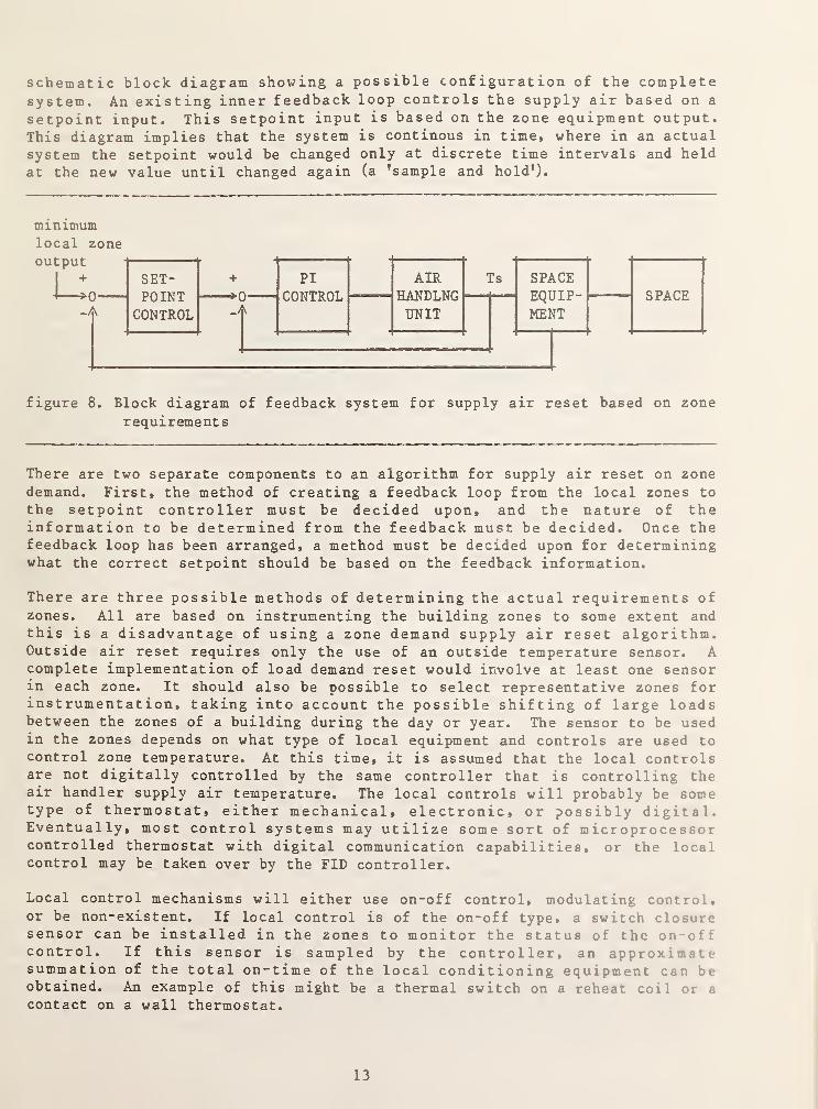
schematic block diagram showing a possible configuration of the completesystem. An existing inner feedback loop controls the supply air based on a
setpoint input. This setpoint input is based on the zone equipment output.
This diagram implies that the system is continous in time, where in an actual
system the setpoint would be changed only at discrete time intervals and heldat the new value until changed again (a ’sample and hold’).
minimumlocal zone
figure 8. Block diagram of feedback system for supply air reset based on zone
requirements
There are two separate components to an algorithm for supply air reset on zone
demand. First, the method of creating a feedback loop from the local zones to
the setpoint controller must be decided upon, and the nature of theinformation to be determined from the feedback must be decided. Once thefeedback loop has been arranged, a method must be decided upon for determiningwhat the correct setpoint should be based on the feedback information.
There are three possible methods of determining the actual requirements ofzones. All are based on instrumenting the building zones to some extent andthis is a disadvantage of using a zone demand supply air reset algorithm.Outside air reset requires only the use of an outside temperature sensor. Acomplete implementation of load demand reset would involve at least one sensorin each zone. It should also be possible to select representative zones forinstrumentation, taking into account the possible shifting of large loadsbetween the zones of a building during the day or year. The sensor to be usedin the zones depends on what type of local equipment and controls are used tocontrol zone temperature. At this time, it is assumed that the local controlsare not digitally controlled by the same controller that is controlling theair handler supply air temperature. The local controls will probably be sometype of thermostat, either mechanical, electronic, or possibly digital.Eventually, most control systems may utilize some sort of microprocessorcontrolled thermostat with digital communication capabilities, or the localcontrol may be taken over by the FID controller.
Local control mechanisms will either use on-off control, modulating control,or be non-existent. If local control is of the on-off type, a switch closuresensor can be installed in the zones to monitor the status of the ono::control. If this sensor is sampled by the controller, an approximatesummation of the total on-time of the local conditioning equipment can beobtained. An example of this might be a thermal switch on a reheat coil or a
contact on a wall thermostat.
13

If local control is of the modulating type, such as a VAV damper, modulatingreheat valve, or dual duct mixing damper, the local sensor should be able to
measure the position of the actuator. This sensor could be a potentiometer or
similar device attached to the valve or damper, producing a change in
electrical resistance with movement of the valve or damper. The measurementof damper position could be either averaged over a time period, sampled for a
peak damper position, or used as a discrete measurement of instantaneous local
equipment output.
If local control does not exist, or attachment of sensors to the localequipment is not feasible, an alternative is to directly measure the spacetemperature (and humidity) in each zone. In any zone there will beoscillations in temperature as conditioning equipment is modulated or turnedon or off, and these oscillations can be monitored with temperature sensors.If the supply air temperature to the zone is exactly matched to the spacerequirements, the temperature oscillations will be minimal. If the the supplyair temperature is incorrect, however, the local temperature will oscillate,if local conditioning equipment is active, or drift outside of allowablelimits, if there is no local control of conditioning equipment. Thisinformation, then, can be used to alter, if necessary, the supply airsetpoint
.
When the feedback loop from the local zones has been implemented, informationabout heating and cooling in all instrumented local zones will be available.This information will be in the form of a value such as a total on-time oflocal conditioning equipment, or an instantaneous, average or peak value forlocal equipment output, or a value for space temperature oscillation frequencyor rate of change. Some method must then be applied to use this informationto determine the proper setpoint for the supply air.
The control of the supply air setpoint at a particular time is usually basedon information from one of the zones served by the air handler. Which zonethis is will probably vary seasonally or even from hour to hour due to changesin solar and internal gains, and will differ from system to system. Table 1
summarizes types of air handler systems, the zone used as a basis for reset,and a general method of selecting a setpoint. The basis for selecting thecritical zone is not the absolute zone heating or cooling load, but is theratio of the energy currently removed or delivered at a zone to the the totalpossible cooling or heating capacity available for a zone. This will be calledthe greatest percentage of maximum capacity. For a reheat system the zone withthe largest percentage of maximum capacity will be the zone with the least useof local reheat. For dual path systems, the critical zone is the one with thegreatest percentage of maximum heating capacity when setting hot deck supplytemperature and the zone with the greatest percentage of cooling capacity whensetting cold deck supply temperature.
For VAV systems, the situation is more complex. To minimize fan usage in a
VAV system, the setpoint in the cooling season should be lowered, and based onthe damper position in the zone of the smallest percentage of the maximumsupply air flow. However, tq minimize chiller energy in the cooling season,higher setpoints are required, and selection is based on the zone with thegreatest percentage of maximum supply air flow. The reverse is true for theheating season. If local heating and cooling equipment is available, the
14

selection of the zone is complicated by factors such as whether some zones are
cooling and others are heating, and the cost of providing heating or cooling.
TABLE 1. Supply air reset criteria for various system types
system type I zone choice I method+ +
1. Mix hot and cold air | I
a. hot deck I Largest hot deck | Lower setpoint if hot deck damperIdamper opening |not fully open. Raise if full open.
I I
b. cold deck |Max. cold deck iRaise setpoint if cold deck damperIdamper opening I not fully open. Lower if full open.
I I
2. Reheat ISmallest amount IRaise setpoint to minimize reheat.I of reheat(small |Lower setpoint if reheat almost
1% of max. cap.) I never on.
I I
3 . Packaged or unitary | I
equip. and central air! I
a. all zones heating Ismallest % of IRaise setpoint to minimize heating.Imax. local heat I
b. all zones cooling Ismallest % of |Lower setpointImax . local cool . I
to minimize cooling.
4.
c. Some zones cooling | Smallest % of IRaise setpoint to minimize heatingSome zones heating Imax cooling if | if winter. Lower setpoint to
Iwinter, smallest Iminimize cooling if summer. Or1% of max. heat ladjust setpoint to minimizeI if summer, (or (expensive local conditioning.I zone with most I
I expensive local I
I conditioning) |
I I
VAV (non-dumping)| |
a. Minimum fan energy | lowest % of max | lower setpoint to minimize air flowI supply air flow I if cooling or raise setpoint to
Iminimize air flow if heating.I I
b. Minimum supply airlLargest % of maxlraise setpoint to maximize air flowConditioning | supply air flow I if cooling or lower setpoint to
Imaximize air flow if heating
Table 1 gives strategies for determining how to correct the current setpoinito minimize energy waste. For systems with local zone equipment which canonly reheat the incoming air, the strategy is simply to minimize reheating <>l
air which has been overcooled. In systems with the capability to both locallyheat and cool air entering the zones, the strategies are complicat'd bvfactors such as whether the zone has a cooling or heating load, how expensive
15

it is to lower or raise the setpoint of the supply air, and whether the zonetemperature is allowed to float between limits (zero energy band). Two levels
of strategies will be discussed. One level will assume that the informationfrom a selected zone is sufficient to determine a new setpoint. This will be
adequate for many systems with simple zone controls without zero energy bandcontrol. A second level is to include other factors and zero energy band zone
control. A general algorithm for the lower level will be developed first.
The relationship between the supply air setpoint and the information from a
zone currently being used to determine the supply air setpoint can usually be
plotted in the form shown in figure 9. Figure 9 is an example for a zone witha reheat coil. The important point about this figure is that when the supplyair setpoint is below the best value to maintain the zone condition, the zoneequipment will have some measurable average output as an attempt is made to
reheat the air to a better temperature. As the supply air setpoint approachesthe best value for this room condition, the zone equipment output willapproach zero. If the supply air setpoint is made too high, the zoneequipment output will remain at zero. However, the zone will probably beuncomfortably warm. When the supply air setpoint is too low, the reheat coilwill remain on. Continuous running of the reheat coil indicates that the roomis too cold, but gives no indication of the error in the supply air setpoint.
For a simple system with local reheat and a constant space temperature, a
practical approach to control of supply air setpoint is to assume that thebest minimum value for zone equipment output is at some level slightly greaterthan zero, and to attempt control of the supply air setpoint to hold the zoneequipment output at this level. If the setpoint is controlled to keep zoneequipment output at zero, and the relationship of figure 9 is applicable, it
is possible to determine that the setpoint is too low (local equipment on),but not if it is too high. By selecting the desired value of zone equipmentoutput to be a small positive value, indicated as the control point in figure9, then if the zone equipment output is zero, the supply air setpoint is knownto be too high.
figure 9. Generalized zone heating equipment output versus supply air setpointfor a given room condition.
16

If the zone equipment is under modulating control and has both local heatingand cooling capability, such as with heat pumps, an output versus supply air
setpoint curve for this zone would have a similar shape compared to the curvein figure 9, but instead of remaining at zero output with increasing setpoint.There would be an increase in cooling output. The equipment would reach a
maximum cooling output and stay there as supply air setpoint were increased.In this case, it is possible to determine if the setpoint is too high, andalso the approximate error in the setpoint. A minimum value of zone equipmentoutput must be specified for the heating and cooling output. The supply airsetpoint must then be controlled to keep the output within the minimum values.
For a dual duct or multizone system, with two supply air setpoints, the local
equipment is usually a modulating mixing box, providing a mix of warm and cool
air. A plot of output versus supply air temperature for one deck would showthe use of all warm air at low supply temperatures and all cool air at highsupply temperatures. In this case the desired supply air setpoint is one whichcauses the mixing box to use air from only one duct (see table 1). Thereforethe desired zone output is when warm or cool air flow is a maximum for thezone. The same principles apply, however, as in the case shown in figure 9,
and therefore the control point should actually be when the warm or cool air
flow is slightly below maximum.
Once a desired value for the local equipment output for the zone identified as
the critical is selected, the actual zone equipment output can be measured,and compared to the desired value to determine how much the current output is
in error. In the simplest case, a gain factor can be applied to the error to
produce a correction to the current setpoint. For example, if a reheat coilis observed to operate 20 percent of the time, and the desired minimum is 5
percent, the error is 15 percent. If the gain is 0.033 degrees C/percent on-
time, the correction to the setpoint is 0.5 degrees C. If the currentsetpoint is 15.0 degrees, the new setpoint would be 15.5 degrees. If thereheat coil in the zone is not operating at all, the error would be -5
percent. The setpoint correction would then be -0.165 degrees.Unfortunately, the setpoint might really be several degrees too high, but it
is impossible to determine this. Thus, the response of the setpointcontroller in this case might be slow when the setpoint is too high, althoughthe setpoint would eventually arrive at the correct value.
More complicated algorithms could be developed to relate the supply airsetpoint to the zone equipment output error, such as adding integration ofpast error to the algorithm (a PI controller). It is beyond the scope of thisreport to develop such algorithms, however.
Figure 10 depicts a general algorithm for supply air reset based on zonerequirements. This algorithm is intended for periodic execution at some ratewhich must be selected based on how many measurements are required to obtainan accurate picture of what is occurring in the zones. Only after a
sufficient number of samples have been obtained from the zones will thealgorithm determine what the new setpoint should be. In figure 10, this is
shown as an early exit from the algorithm if not enough samples have beencollected. Each time a new set of samples is taken, the new set is eitheradded to or averaged with the previous measurements and a count of the nuu In i
of samples is incremented. If a measurement of modulating control out.jut in
17
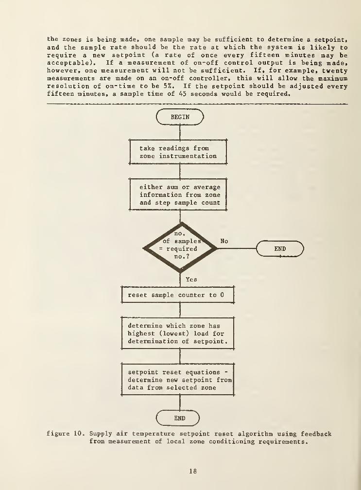
the zones is being made, one sample may be sufficient to determine a setpoint,and the sample rate should be the rate at which the system is likely torequire a new setpoint (a rate of once every fifteen minutes may beacceptable). If a measurement of on-off control output is being made,however, one measurement will not be sufficient. If, for example, twentymeasurements are made on an on-off controller, this will allow the maximumresolution of on-time to be 5%. If the setpoint should be adjusted everyfifteen minutes, a sample time of 45 seconds would be required.
figure 10. Supply air temperature setpoint reset algorithm using feedbackfrom measurement of local zone conditioning requirements.
18

After sufficient samples have been taken from the zones, the sample counter is
reset, and the algorithm is ready to determine a new setpoint. Adetermination of which zone to use as a basis for the new setpoint is made,based on the type of the air handler system and the season. Rules for thiswere discussed previously. Once a single value for local zone activity hasbeen determined, this can be used as input to equations to predict what a newsetpoint should be and the setpoint can be altered. The equations used can be
multiplication of an error in zone activity by a simple proportional or gainfactor to produce a desired change or setpoint. More complex equations arecertainly possible.
An example supply air setpoint reset algorithm based on the procedure in
figure 10 is described in section 7.3. The system controlled in the exampleis a constant volume, terminal reheat system, with two zones. Actual softwarelistings for the algorithm are included in appendix B. The basic algorithm is
also applicable to dual duct systems, if the zone determination step is
expanded to include a selection of separate zones for the hot deck and colddeck setpoints, and the setpoint equations are expanded for hot and cold decksetpoints
.
If the zones in a building are under zero energy band control, morecomplicated algorithms than the one in figure 10 may be necessary to optimizebuilding energy use. If, for example, the temperatures of the zones in a
building were all floating between limits, but none were at the limits, and if
mechanical equipment were being used to cool the supply air, energy would bewasted. If the supply air setpoint were adjusted to move the spacetemperature closer to the high limit, mechanical cooling would be reduced, andenergy would be saved. More sophisticated instrumentation would be requiredfor this application, such as sensors for measurement of space temperature orthermostats with analog or digitized analog output.
19

4. DAY/NIGHT SETBACK
Most commercial buildings are not occupied 24 hours a day* and do not require
space conditions to be within a comfort zone when unoccupied. When the
occupants leave a building, usually at night or on weekends, the spaceconditions can be allowed to drift outside of the usual setpoints for spacetemperature and humidity. If weather conditions are not severe, the HVACequipment can be turned off completely. In many cases, however, weatherconditions might result in space temperatures becoming so low or high as to
either cause damage to the building (e.g. freezing, condensation, highhumidity), or make it impossible to recover to a comfortable temperaturebefore building occupation. In such cases the HVAC equipment must beactivated to keep the space at a minimum or maximum temperature or humiditycondition. The temperatures and humidity values at the minimum or maximumconditions replace the normal occupied period space setpoints. This strategyis commonly called "setback”. Setback is usually associated with a loweringof space temperature setpoint. If the space temperature setpoint is raised,such as during the cooling season, this may be referred to as "setup.” Themodifier "day/night” is also added to the term "setback,* to imply that thesetback occurs at night. However, some buildings may have occupancy schedulesnot related to day and night, such as theatres and churches.
Space comfort condition specification also includes a minimum ventilationrate. This is commonly set at a minimum value for all conditions and is not
under closed loop control. If the ventilation rate is placed under control,then the setpoint of minimum ventilation air can be setback, just as thetemperature can be setback. Usually the ventilation level is setback to zeroby closing the outside air dampers during unoccupied periods.
4.1 Local Space Equipment
Day/night setback is usually accomplished throught the control of localheating and cooling equipment located in the zones of a building, since thisis the equipment which directly determines the space temperature. Althoughthe basic concept of day/night setback is simple, the design of a generalsetback algorithm is complicated by the number of different system types andlocal equipment configurations. Day/Night setback is applicable to anybuilding in which space conditions may be allowed to drift out of normalranges at any part of the day. However this discussion will be limited tonon-residential buildings which contain a central air handling systemproviding ventilation air and possibly conditioned air to the building spaces.
Table 1 in chapter 3 gave a listing of four generalized air system types whichmay serve a building zone. These types may be mixed in any particularbuilding, with one type of system serving, for example, a perimeter zone andanother type serving an interior zone. The actual control of local spaceconditions is usually accomplished by a separate controller device located inor adjacent to the zone. This device will be referred to as a thermostat,although more complex controllers such as those used in VAV systems might notusually be referred to by this term. Table 2 is a listing of the possibletypes of thermostats which might be used to control zone temperature.
20

TABLE 2. Space zone thermostat types
thermostat type I system type Icomments
1. On-off heating or
cooling only1 reheat, package | Setup and setback not possible at
lAC or HP, | same time. Manual choice of heating
1 radiation lor cooling equipment control.
1 1
2. On-off heating and
cooling
1 1
1package AC or HP | Setup and setback not possible at
I | same time. Controls both heat and
1 Icool equipment at same time. Subject
I | to cycling from heating to cooling.1 1
3. On-off zero energyband heating and
cooling
.
1 1
1package AC or HP I Setup and setback possible at same
1 I time. Gap between use of heating and
|| cooling equipment.
1 !
4. Analog heating or
cooling onlyIVAV, modulating I Setup and setback not possible at
1 reheat, hot/cold I same time. Manual choice of heating
lair mixing lor cooling equipment control.
I | Produces variable output.1 |
5. Analog heating andcooling
8 1
Ihot/cold air I Setup and setback not possible at
Imixing system, | same time. Produces variable output
|4 pipe fan coils | on one or two output lines,
land radiation
6. Analog zero energyband heating andcooling
l l
|4 pipe fan coils I Setup and setback possible at same
I Itime. Gap between heating and
1 | cooling signals.
1 1
1 1
In table 2, the thermostats are one of two basic types, either on-off oranalog. On-off thermostats produce either no output signal or an outputsignal of a fixed level. The output can be used to turn on or off equipmentwhich is to be either fully on or off. Analog output thermostats can be usedto modulate the output of zone local equipment. The output of such a
thermostat varies with the difference between the setpoint and the measuredspace condition. In addition, thermostats can be classified as either zeroenergy band or conventional. A conventional thermostat is used to maintain a
space at a fixed setpoint. A zero energy band thermostat is intended to allowthe space condition to float between limits which may be as much as 5-10degrees G apart.
Table 2 implies that zero energy band control is not possible with certainsystem types. Strictly speaking, this is true, since zero energy band controlat the zone level requires that the zone controls be able to both locally heat
and cool the zone. In a system such as a terminal reheat system, the cooling,
of the zone is provided by the temperature of the air from the air hand 1 ' i ,
21

which the reheat thermostat has no direct control over. However, it is
possible to provide effective zero energy band control for the zones if thelocal thermostat can provide a signal to the air handler controller wheneverthe local zone is outside of zero energy band limits. For example, with a
terminal reheat system, the local thermostat could provide a signal if thespace temperature were above the upper space temperature limit. In this casethe supply air temperature could be adjusted upward until either mechanicalcooling at the plant could be turned off or until the zone temperature was at
the upper limit. If the zone temperature were below the limit, the localreheat coil would keep the zone at the limit.
Local zone thermostats can be implemented in many types of devices. Athermostat can be mechanical, with a bellows or bimetallic strip moving a
mercury switch, or pneumatic, with a fluid filled temperature sensor producinga fluid pressure which is converted to an air pressure, or electronic, using a
sensor producing an electrical output signal. Many new thermostats are beingdesigned with microprocessors and digital interfaces. Most thermostats havetraditionally been set, calibrated, or programmed at the thermostat location.Thermostats to provide day/night setback have been built with internal clocksto switch between day/night setpoints. In order for day/night setback to
become a function controlled by a BMCS (EMCS), the local thermostats must havethe abiltity to either switch between locally programmed setpoints on thereception of a signal from a remote controller, or to have the setpointdirectly programmed by the remote controller. Another concept is to have the
remote controller take over the function of the local thermostats.
To reduce manual reprogramming requirements for setback of local thermostatsat the transitions between cooling and heating seasons, it may be possiblewith some thermostats to implement cooling setup and heating setback at the
same time. For a zero energy band thermostat, this requires that the zeroenergy band be increased in size on both ends of the band.
Control of the ventilation air provided to a space is usually not implementedlocally. The criterion for acceptable space conditions is usually a minimumquantity of outdoor air per occupant of a zone. Some systems measure eitheroccupant count or carbon dioxide concentration to control the amount ofventilation air. If a zone has no occupants, no ventilation air is required.The outdoor air quantity is varied by changing the opening of the air handlersystem outside air dampers. In this report, only change of ventilation airquantities from occupied conditions to unoccupied conditions will beconsidered
.
4.2 Spacjg. Temperature and Ventilation Setback
When temperature and ventilation setback are to be considered for use in a
particular building zone, the characteristics of the zone will determine to
what degree setback may be used. If a zone is occupied continously, then nosetback will be possible. Examples would be security guard offices orbuildings with multiple shifts of workers.
If the zone is unoccupied for part of the day, but sensitive equipment ormaterials are located in the zone, or temperature sensitive equipment runs
22

con t inou s ly # then a limited setback may be possible. If the equipment or
materials do not require ventilations but do require a certain temperaturerange, it may be possible to shut off ventilation air to the zone. Examples
of this type of zone would be computer rooms, laboratories, or rooms forstorage of temperature sensitive chemicals.
If a zone is unoccupied for part of the day and contains no sensitiveequipment or materials, a setback of the zone temperature is possible. Thelocal controller can be setback to a temperature which is above anytemperatures where damage to the zone might occur, or setup to a temperaturewhich is below a temperature where heat damage might occur. Often the coolingability of the space is disabled since heat damage requires very high outdoortemperatures or solar gain rates. Unless the local climate is mild, heatingequipment is not disabled since cold damage such as condensation or freezingmay occur at temperatures not that far below room temperature. A buildingzone whose setpoint has been setback can maintain the minimum spacetemperature by one of two methods. Many systems have a local perimeterheating system which does not require the central air system to be operating.Examples are terminal reheat systems with coils in the zone space (induction),or perimeter hot water radiation coils. In such systems the air handler fansmay be completely shut off during the setback period. If a local perimeterheating system does not exist, the air handling system must be used to providewarm air to the space. Examples would be VAV, dual duct, or multizone systemswithout local zone heating equipment. In this case the air handler fans musteither be left operating or cycled on and off to maintain the minimum spacetemperature
.
A consideration in setback or setup of thermostats is that when the thermostatsetting is returned to normal before the start of the occupied period, localheating or cooling equipment may turn on at full output. In some systems thismight be undesirable and it might be necessary to delay the return to thenormal thermostat setting until after the air handling unit has started.
4.3 Day/night Setback Actions
The use of day/night setback involves two separate procedures. These are thetransition of the building to the setback condition, which will be referred toas shutdown," and the transition of the building from the setback to thenormal condition, which will be referred to as "startup."
For shutdown the actions that may be taken are as follows:
1. thermostat setback and/or setup - this action causes the local zonecontrol equipment to use a minimum and/or maximum space condition as tht
zone thermostat setpoint.
2. stop air handling unit - this action is used when the zone can maintainthe minimum or maximum condition without assistance from the air handler.
3. change operation of air handling unit controller - this action i:
required so that the air handler controller will not attempt to control
23

the unit in the same way as it would under normal conditions. Thisincludes the operation of automatic supply air setpoint resetcontrollers (see chapter 3).
For action 1, the control unit (FID) which manages the shutdown must eithersend a signal to the local zone thermostats which will cause them to use a
setback and/or setup setpoint for the zone, or somehow reprogram the zonethermostats to use an alternate thermostat setting. The choice of whether toforce a setback or setup thermostat setting may have to be made as a functionof the season. If the local zone equipment is not capable of maintaining thespace condition without the air handling unit, then either the FID mustmonitor the zone conditions and restart the air handler if the spaceapproaches minimum or maximum condtions, or the local zone thermostat mustprovide a signal which the FID can interpret as indicating that the zonerequires that the air handler be activated.
Action 2, stopping the air handling unit, will usually consist of a number of
separate actions including stopping the supply fan, and if present, a returnfan, shutting valves to heating and chilled water coils, shutting all outsideair dampers (including minimum outside air dampers), and stopping anyauxiliary pumps or fans. If the zones require that the air handling unitprovide conditioned air during setback, action 2 would consist only of
shutting outside air dampers, and some of the non-essential air handlersupport equipment.
Changing the operation of the air handling unit controller, action 3, is
required to prevent the controller from trying to maintain a supply airtemperature when there is no airflow through the unit. If the FID is alsorunning an algorithm to reset supply air temperature setpoint, it may benecessary to disable this algorithm, unless the supply air setpoint is
initialized at the startup of the air handler.
For startup, the following actions may be required:
1. removal of thermostat setback and/or setup
2. start air handling unit
3. return operation of air handling unit controller to normal
For startup action 1, the control unit (FID) which manages the startup musteither send a signal to the local zone thermostats which will cause them touse the normal setpoint for the zone, or reprogram the zone thermostats to usethe normal thermostat setting. Startup action 2, starting the air handlingunit, will usually be the opposite of stopping the unit. The start operationswill include starting the supply fan, and if present, the return fan, openingoutside air dampers for minimum ventilation, and starting any auxiliary pumpsor fans. A delay between successive starts of separate pieces of electricalequipment should be used to avoid high utility demand charges. Returning theoperation of the air handler controller to normal will cause the outside airdampers and heating and cooling coils to open as needed. If the FID is alsorunning an algorithm to reset supply air temperature setpoint, it may benecessary to initialize the supply air setpoint at the startup of the air
24

handler. Action 1 may be performed after 2 and 3 in certain situations where
local equipment might turn on unnecessarily when the space setpoint is
returned to normal.
4.4 Basic Setback Algorithm
The shutdown and startup sequences described in section 4.3 will be usedbefore and after an unoccupied period. These sequences can be initiated in
one of three ways. The simplest method is by a manual command to the FID froma building operator to either startup or shutdown. The disadvantage of this
is that the operator must always be present before the sequence is to occur.
Also the timing of the shutdown and startup determines the energy savingswhich will result from the use of setback. A manual setback will yielderratic savings if the operator forgets or is late in starting a sequence.
A second method is to use "time of day" control to initiate a setbacksequence[4]. This method uses an algorithm in the FID which allows a "task
to be scheduled to occur at a specific time of day on a specific day of theweek. A setback shutdown could then be scheduled to occur at, for example,5PM, Monday through Friday, and a startup could be scheduled to occur at 6AMMonday through Friday. The startup time would have to be scheduled to allowenough time for the HVAC equipment to bring the building from the setbackcondition back to the normal state before the building were occupied. Thistime will vary depending on the severity of the weather. During the spring,the startup might require one half-hour, while during severe winter conditionsthe startup might require as long as 8 hours. To some extent the schedule canbe changed to reflect the weather, but maximum savings occur if the end ofstartup recovery always coincides with building occupancy. With shutdown, thesequence may be scheduled to start when the building occupants leave.However, the shutdown can often be started prior to the unoccupied period andspace conditions will not deterioriate out of the comfort region until afterthe building is unoccupied. To achieve the maximum savings with setback, thesetback startup and shutdown should be controlled by an "optimum start/stopcontrol algorithm, which makes calculations based on outside conditions andthe past behavior of the building to select the best time to begin startup andshutdown[ 5]
.
Figure 11 represents a basic algorithm that would be used for day/nightsetback shutdown and figure 12 presents the basic algorithm for startup.These algorithms would be executed under control of one of the three methodsmentioned in the preceding paragraph. The setback actions were described in
detail on previous pages.
An example of setback algorithms based on the procedure in figures 11 and 12
is described in section 7.4. The system controlled in the example is a
constant volume, terminal reheat system, with two zones. Actual softwarelistings for the algorithms are included in appendix C.
25

BEGIN
figure 11. algorithm for day/night setback from normal to setback state
figure 12. day/night setback algorithm for return to normal state from setback
26

5. VENTILATION PURGING
Ventilation purging is a control strategy which uses outside (ventilation) air
to reduce energy requirements and improve occupant comfort. This strategy is
intended to operate in a building which has unoccupied periods when it is
possible to allow space conditions to range outside of an envelope of
acceptable dry bulb temperatures, humidity, and fresh air requirements.Ventilation purging is not useful in a building which must maintain comfortconditions at all times. Purging is defined as the use of outside air to
either heat or cool a building during unoccupied hours (depending on theanticipated loads) if the outside air is at the correct conditions relative to
the inside air. Ventilation purging is usually used as a cooling strategy.During the cooling season, cool outside air in the early morning (e.g. 4AM)can be used to precool a building if the outside air is cooler than the aircurrently in the building. This precooling can reduce the cooling capacityrequired for occupied period startup.
5.1 Basic Concepts
The ventilation purging concepts discussed here are assumed to apply to the
use of purging as a cooling strategy. The usefulness of ventilation purgingto provide inexpensive cooling during an unoccupied period depends on thecharacteristics of the particular building in which the strategy is to beused. Two characteristics are of primary influence. These are the buildingthermal mass and the unoccupied period internal gains. The ideal applicationfor ventilation purging is a building with high thermal mass and lowunoccupied internal gains, located in an area where the outdoor temperaturesduring the unoccupied period are lower than the temperatures during theoccupied period. If outside air is used to purge such a building at night,then because the internal gains are low and entering air is relatively cool,the building mass will approach the outside air temperatures much more quicklythan if no purging were used. This results in interior temperatures near thelower end of the comfort range by the time the building is to become occupiedagain. The high mass keeps building temperatures down for a relatively longperiod with subsequent reduced mechanical cooling equipment loads compared todays where purging is not used.
If a building has high internal gains during the unoccupied period,ventilation purging is still beneficial, but if the purging period is nottimed correctly, savings can be negated. Timing considerations will bediscussed in section 5.3.
Ventilation purging will not be desirable if the outside air temperature doesnot drop appreciably during the night, or if the building has very low thermalmass and low unoccupied internal gains. If the outside air temperature is notlower than the internal temperature, purging the building with outside airwill actually increase cooling loads. If the building has low thermal massand low internal gains during the unoccupied period, the interior temperature s
will normally follow the outside temperature changes closely and ventilationpurging will have no useful effect.
27

In order to make use of ventilation purging, the building air handlers must be
capable of a "purge cycle." A purge cycle usually begins with an air handlingunit in an off state with all heat exchanger water and steam valves fully offand outside air dampers closed. This state would have been entered when the
building became unoccupied. To begin the purge, the air handling unitcontroller must start the air handling unit supply fan, and possibly thereturn fan (if one exists), and fully open the outside air dampers. Outsideair will then flow into the building space, and air in the building spaceswill be exhausted to the outside. In some systems such as VAV systems, thezone supply air boxes may have to be forced to a fully open condition. To endthe purge, the air handling unit fans will be stopped and the outside airdampers closed. Throughout the purge, any heating or cooling coils will notbe allowed to operate.
An example of the temperature response of a building during a purge cycle is
useful to illustrate concepts. Figure 13 is a graph of the average interiortemperature, the outside air temperature, and the air handler supply airtemperature for a simulated building during the course of an unoccupiedperiod. The simulation is for a single constant volume air handler servingtwo zones with terminal reheat. The figure can be divided into six timeperiods when the air handling unit is in different states. At the start of
the figure, the air handler is in the "normal" state and the building is
occupied. The space temperature is at approximately 24 C. The fan is on andthe supply air temperature is below 15 C due to mechanical cooling. Duringthe next period, the fan is off, but the space is still occupied. Due tointernal gains, the space temperature rises. The supply air temperature is
shown as approaching the space temperature, but this is not significant sincethere is no air flow through the air handler. The building is unoccupiedduring the next time period (III in figure 13) and this causes internal gainsto be lower and the space temperature to fall. During this period the outsideair temperature drops to a lower value. In period IV, the ventilation purgetakes place. The fan is activated and the supply air temperature quicklyreaches the outside air temperature. The room temperature drops due to the
purging. In region V the purging has stopped and due to internal gains thespace temperature rises slightly. Finally, in period VI, the air handlingunit is started and placed in a normal mode in preparation for the nextoccupied period.
Two important quantities should be observed in figure 13. One is the smallestdifference between room temperature and outside temperature that the purgingcan achieve (marked as A -
n in figure 13). The magnitude of this differentialdepends on the amount of unoccupied internal gain and the heating of the airdue to fan temperature rise and duct gain as it passes through the airhandling unit. As this minimum is approached, the room temperature will notdecrease unless the outside temperature drops. The purging has no effect atthis point. The other important item is the time required for the system toarrive at the minimum differential between room and outside air temperatures.This is the purging time, and it depends on factors such as the indoor andoutdoor temperatures, the building thermal mass, the supply air flow rate, andthe internal gain.
28

TEMPERATURE,
TIME
figure 13. Space, supply and outside air temperatures during an unoccupiedperiod with ventilation purging
Three types of measured data are required to implement a ventilation purgingalgorithm in a BMCS. The current state of the air handler used for purgingmust be known. In addition, measurements of outdoor air temperature (andhumidity) and indoor air temperature (and humidity) must be made. Themeasurement of outdoor temperature is straightforward, but the determinationof indoor temperature can be difficult. In a single zone small building, theindoor temperature can be easily determined from a single measurement.However, if the building is large, with multiple zones, and diverse internaland solar gains, each zone may be at a different temperature, particularlywhen the air handling units are off during the unoccupied period. Twoalternatives to indoor temperature determination in this case are computing anaverage indoor temperature from a number of individual readings, or usingselected temperature readings from zones with the highest and lowesttemperatures. For determining when a purge is required, the highesttemperature reading might be used. For determining when a purge should b<
stopped, the lowest reading might be used.
The use of ventilation purging can actually be considered an extension of tin-
optimum start/stop control strategy [5]. With optimum start, the optimur tim-
29

to begin the start up of air handlers and mechanical cooling equipment prior
to the occupied period of a building is determined. The desired start time is
just early enough to allow the building space to be brought to a comfortablestate a short time before the building is occupied. If used in conductionwith optimum start time control, ventilation purging might be performed beforethe building start-up, or as a first stage in building start-up. In thisreport, the concerns involved in coordinating optimum start and ventilationpurging strategies will not be discussed. Ventilation purging will beassumed to be an independent control technique.
5.2 Basic Algorithm fox Ventilation Purge Control
A basic algorithm for ventilation purging must determine whether ventilationpurging should be started if the building is unoccupied, or if purging is
currently taking place, whether ventilation purging should be stopped. Figure14 shows the structure of such an algorithm. It is assumed that a mechanismexists in the FID to periodically execute this algorithm at a selected timeinterval, such as every thirty seconds. The algorithm has three possibleoutput actions each time it is executed. These are do nothing, start purging,or stop purging. The actual actions required to start and stop purging areassumed to be performed by another algorithm which is controlling the airhandling unit, such as the controller described in section 7.2.
The algorithm of figure 14 has two major paths, one used if purging is
currently taking place, and the other used if purging is not currentlyoccurring. The determination of whether or not the air handler is purging is
assumed to be made by checking a status variable which has been set by the airhandling unit controller.
Each major path of the algorithm asks two questions to determine what actionshould be taken. Both paths ask the same two questions, but the answer willdepend on which path the question was asked by. The two questions are Doesthe building space require cooling?’* and "can outside air provide a coolingeffect on the building space?." The answers to these questions are determinedby using measurements of the space and outside air temperatures, along withseveral parameters. Specific methods to answer the questions are discussed in
the next section.
The algorithm in figure 14 may be stated in words as follows: If the airhandling unit is off, the space requires cooling, and the outside air canprovide cooling, a purge is begun. Otherwise no purge is started. If a purgeis currently taking place, and either the space no longer needs cooling, orthe outside air cannot provide cooling, the purge is stopped. Otherwise thepurging is allowed to continue.
5.3 Ventilation Euj.&in& Al&fixithm Components
The two main component questions of the ventilation purging algorithm offigure 14 are presented in greater detail in figures 15 and 16. Detailedmethods for answering the questions are presented in the following sections.
30

4
STOP PURGE
<
END ^figure 14. Basic ventilation purging algorithm
5.3.1 Does the space need cooling? / not currently purging
This component of the ventilation purging algorithm determines whether thebuilding space would benefit from ventilation purging during the unoccupiedperiod. A simple test is to compare the current space conditions to spac.
conditions definined as boundaries of a comfort zone. If the space condition.^
are warm or humid compared to the comfort zone conditions, then cool in* ;*
needed. If the space conditions are cooler or dryer than the comfort zon--
conditions, cooling is not needed. A threshold condition within the contortzone must be defined, above which cooling is needed. This method will vi r>.
the space conditions have reached a steady state condition.
31

figure 15. Algorithm to determine if the building space requires coolingfor the ventilation purging algorithm.
When the space becomes unoccupied, the space temperature may drop rapidly due
to causes such as low outside temperatures or the removal of a large internalgain. Purging may not be desirable even though the space temperature is abovethe cooling threshold because the space temperature may reach comfortabletemperatures without the use of purging. A second test, which determines if
the space temperature is currently rising or holding steady, should be used in
conjunction with the threshold test. An example method for determining thespace temperature trend is given in section 7.5. These two tests to determineif the space requires cooling are shown in the left side of figure 15. If theresult of both tests is positive, then cooling is needed. If the result ofeither test is negative, then cooling is not needed.
32

5.3.2 Does the space need cooling? / now purging
Once ventilation purging is in progress, the building space temperature should
fall, if the decisions made by the purge-starting path of the algorithm have
been correct. Eventually the space temperature will either level off at a
value within or above the comfort zone, or, under certain conditions, at a
point below the comfort zone. If the space temperature falls below thecomfort zone, then heating energy will be required to bring the temperatureback up, negating the benefits of the purge. Therefore it is important to
stop the purging if the space temperature falls too low. This is accomplishedby comparing the space condition with a lower limit. If the space conditionfalls below the limit, then cooling is not needed. As long as the conditionstays above the low limit, then cooling is still needed. This test is part of
the algorithm in figure 15, and is shown on the right side of the figure.
5.3.3 Is cooling available? / not currently purging
This test is intended to determine if starting the use of ventilation purgingwill provide practical cooling of the building space at the current time. As
was shown in figure 13, if ventilation purging is started under the properconditions, the space temperature will fall and level off at a value above theoutside air temperature. To start purging when the differential between the
space and outdoor temperatures is below the minimum differential would resultin no useful cooling effect. Unfortunately the minimum differential is not a
constant for all buildings, since it depends on building internal gains,thermal mass, and heat transfer coefficients. This differential could,however, be considered to be a constant for a particular building. The testfor availability of cooling would then be to compare the current differencebetween indoor and outdoor temperatures with a minimum differential parameterwhich could be set by the building operator. Improper choice of a minimumdifferential parameter would result in either waste of fan energy or missedopportunities for useful ventilation purging.
To prevent damage to the air handling system when outdoor temperatures arelow, a test should be made to determine if the outside temperature is lowenough to cause freezing of heat exchange coils. The two tests fordetermining if cooling is available are shown on the left side of figure 16.
If the outside temperature is above a safe minimum, and also the differentialbetween indoor and outdoor air temperatures is above a minimum, then coolingfrom ventilation purging is considered available. If either of the two testsis not passed, ventilation purging is considered unavailable.
In areas where relative humidity is high during the cooling season, it is alsoimportant to include a comparison between indoor and outdoor relativehumidity. If outdoor air is cooler than indoor air, but the relative humidityis high (such as during a rainstorm), ventilation purging should not bestarted, since the latent cooling load will actually be increased.
33

BEGIN
purge Yes
figure 16. Algorithm to determine if outside air can provide cooling usedfor the ventilation purging algorithm.
5.3.4 Is cooling available? / now purging
The purpose of this test is to determine if ventilation purging is continuingto have a cooling effect on the building space. In general, the spacetemperature will fall rapidly at the start of purging and approach a steadyvalue. By monitoring the trend of the space temperature, a decision to stoppurging can be made when the rate of decrease in space temperature has becomeso slow that further purging will not provide additional cooling. An exampleof a method for determining whether the space temperature is falling is givenin section 7.5 (the same method is used to determine if the temperature is
rising or steady). The test for continuing cooling availability is shown in
the right side of figure 16.
34

If high relative humidity is a consideration, it may also be necessary to
stop purging if the outdoor relative humidity rises above the indoor relative
humidity. The indoor humidity will approach the humidity of the outdoor air
in the same fashion as the temperature.
5.4 Ventilation Purge Algorithm Timing,
The optimum starting time for ventilation purging when all of the tests
described in section 5.3 have been passed depends to some extent on the
characteristics of the building where the algorithm is applied. At first it
will be assumed that the ventilation purge algorithm is executed periodically
for the entire unoccupied period. If ventilation purging is started as soon
as the tests of section 5.3 are passed, and the purging is stopped some timelater by the algorithm of figure 14, the space temperature could conceivably
rise and cause ventilation purging to be initiated again. Under certainconditions, the purge cycle might take place two or more times. Unless an
attempt is being made to maintain the space at some condition with purging,
the most important result of the purging is that when the building is occupiedthe space conditions are in the lower part of the comfort zone. If the purge
cycle takes place more than once, the cycles before the last one will wastefan energy.
Excess cycling of ventilation purging is more likely to occur in a buildingwith high unoccupied internal gains. In a building with low internal gains,
once the space has been cooled to a minimum temperature, it will probablyremain there once purging is stopped. Thus the time-of-day that the purgingtakes place is less critical. In such a case, the most important timingconsideration is that the purging take place at a time when outdoor airenthalpy is at its lowest. This can be accomplished by time-of-day control orby monitoring the trend of outside temperature.
To prevent excess cycling of a ventilation purge, the simplest approach is to
only begin periodic execution of the purge algorithm a relatively short timebefore the startup of equipment for the occupied period. The approximate timerequired to purge the building can be used as a guideline for how early thepurge algorithm should start. A time-of-day control algorithm can be used toschedule the starting of the ventilation purge algorithm [4],
A more complicated method of causing the purge to occur just before thestartup for the occupied period requires that records of purge times, andoutside and indoor temperatures at the start of previous purges be kept. Thisinformation can be used to predict the time that will be required to purge thebuilding. This method is actually a form of optimum start algorithm, and if
an actual optimum start algorithm is being used for the startup of the airhandler system, the control algorithms must be carefully designed to preventconflicts
.
An example algorithm used in the actual NBS FID and based on the algor it hi: < :
figures 14, 15, and 16 is presented in section 7.5. The system control]''! i r.
the example is a constant volume, terminal reheat system, with two zone.,thermal mass, and high internal gains. Actual listings of software for th-
example are included in appendix D.
35

6. HOT WATER AND CHILLED WATER SUPPLY TEMPERATURE RESET
HVAC equipment is usually sized to meet conditions at a design peak load.Coil water temperature setpoints are also chosen to meet the design load.
During most of the equipment operating hours, the equipment will be operatingat part-load conditions. Use of design setpoints on water loops at part-loadresults in unnecessary piping loss (or gain for chilled water) and possiblyequipment inefficiencies. Setpoint reset control reduces energy consumptionby performing a reset of hot water or chilled water supply setpoints to matchthe actual equipment load. Usually the supply water setpoint is constant for
an entire HVAC system, since the water will typically be supplied from boilersor chillers in a central plant.
6.1 Outside Ml Temperature Sjjp_p_ly. WiLtgr
The goal of water supply temperature reset is to supply the various heatexchange coils that use either hot or chilled water with water at a
temperature which is just sufficient to supply the load at the coil with the
greatest demand. For example, if all chilled water coils in a system of air
handling units have their valves open somewhere between 5 and 40 percent, thisindicates that the coils are not at full load, and that the chilled watertemperature could be raised to improve chiller economy and lessen piping heatgain. After the chilled water temperature is raised, the chilled water valvesmight be open from 70 to 85 percent, which is close to the full load of thecoils. The coil with the greatest opening determines the limit for thereset. When any of the valves in the system reaches 100 percent open, thenthe chilled water temperature should be lowered, because the fully open valveindicates that this particular coil is at or above full load, and might not beable to provide sufficent cooling capacity for the air handling unit.
An approximate method of implementing supply water reset is to assume that thespace load is a function of the outside air temperature. As the outside airtemperature rises, chilled water temperature is adjusted downward and hotwater temperature is adjusted downward. The algorithm for outside air supplywater reset is functionally the same as the outside air supply air resetalgorithm, as discussed in section 3.1 and presented in figure 6. Because ofthe similarity to outside air supply air reset, outside air supply water resetwill not be discussed further in this chapter.
6.2 Demand Supply Water Temperature Reset
A more accurate method of supply water reset than outside air temperaturereset is based on readings from instrumentation of actual heat exchangercoils, either the valves or the coils themselves. This will be referred to asdemand supply water reset. Demand supply water temperature reset control is
different from the other strategies discussed in chapters 3-5 because a demandsupply water reset algorithm cannot be placed in a single FID associated withan air handling unit. The plant equipment for production of hot and chilledwater is likely to be controlled by a FID unit or controller which is
physically separated from the FIDs or controllers which oversee the airhandling units in a building. There may be a controller, located in a plantFID, which maintains the hot or chilled water system at a setpoint. Thealgorithm to determine what the water system setpoint should be might reside
36

in the plant FID, or at the central control level of the system. If thedemand water reset algorithm is to monitor the coil loads at the individualair handlers, there must also be algorithms in the air handler FIDs, in
communication with the main demand supply water reset algorithm, to provideinformation on valve positions or coil conditions. There are several possibleconf igurations
.
The simplest configuration of algorithm location for demand supply water reset
is to have the main algorithm at the central control level. Information onthe air handling units is obtained by the central control unit (CCU) and usedby the reset algorithm. The selected supply water temperature is thentransmitted to the control unit which is maintaining the supply watertemperatures. This configuration has the disadvantage that the central unit
is required in the system at all times. An alternative architecture mightconfigure the CCU as only an operator interface device, which would notexecute many control algorithms. The demand supply water reset algorithmmight then reside at the FID level in a plant FID, and obtain information fromroutines in the air handling unit FIDs through the BMCS communication system.
The air handler information might be transmitted through the CCU or directlyto the plant FID, depending on what sort of communication network existed for
the system.
The demand supply water reset algorithm is therefore divided into twophysically separate parts, the actual setpoint determination and control part,
and the air handler load determination part. The air handler loaddetermination part is distributed among the FIDs which control air handlingequipment. The information which must be supplied by the load determinationpart to the setpoint determination part depends on the sophistication of the
algorithms in the air handling unit FIDs. The highest level of informationwould be a suggested supply water setpoint based on the local air handlingunit load. The setpoint determination part would then consist of selectingthe highest hot water or lowest chilled water setpoint suggested by all of theair handler FIDs. Table 3 contains a list of several possible levels ofinformation that could be determined by the load determination algorithms.
The information in table 3 is organized in order of load determinationalgorithm complexity with more complex algorithms required by the first item.Conversely, as the load determination algorithm becomes more complex, thesetpoint determination part becomes simpler. The advantage of greater loaddetermination algorithm complexity is that the amount of information about airhandling units that must be known by the setpoint determination part of thealgorithm is minimized, making the total algorithm more flexible.
Table 3. Possible information transmitted between parts of a supply waterreset algorithm.
1. suggested water setpoint2. suggested change in water setpoint (+ or -)
3. suggested direction of change in water setpoint (up, down, or no change)4. average valve position or average valve position error5. averaged binary valve position (eg: above 80% / below 80%)6. average coil inlet and outlet temperatures
37

6.3 Possible Demand Sitpjtlx HfllLfiX &££££. Lo&A Algorithm
A possible demand water setpoint reset load determination algorithm might use
a hot water or chilled water valve' instrumented with a potentiometer to
measure absolute valve position and produce as an output a suggested increaseor decrease in supply water setpoint. The algorithm output would be used by a
supply water reset setpoint selection algorithm. Figure 17 presents how suchan algorithm might be structured.
The algorithm of figure 17 is intended for periodic execution at an intervalwhich must be selected for the system being controlled. The first part of the
algorithm is used to create an average value of valve position. If a
sufficient number of samples for an average have not been taken* then thealgorithm is exited.
Once an average valve position has been determined, this valve position is
compared to a desired valve position which has been selected as a point withgood control characteristics. The desired valve position is actually a rangeof possible valve positions* with lower and upper target values. If theaverage valve position is determined to exceed the upper target value, thisindicates that supply water temperature should be decreased for a chilledwater valve or increased for a hot water valve. If the average valve positionis determined to be less than the lower target value, the supply watertemperature should be increased for a chilled water valve and decreased for a
hot water valve. If the valve position is between the upper and lower targetvalues, then no change in setpoint is suggested. If a change is needed, anoptional calculation can be made to estimate the magnitude of the change to be
suggested. This value, in degrees of temperature, is combined with thedirection of change determined previously to produce a suggested supply watersetpoint for the setpoint determination part of the supply water resetalgorithm.
The calculation to determine the size of the suggested change in supply watersetpoint is performed using the error between the appropriate target value forvalve position and the average measured valve position. This error is
multiplied by a proportional factor with units such as degrees C/percent valveposition. This factor is dependent on the characteristics of the valve andheat exchanger using the supply water, and would probably be determinedexperimentally by observing a valve’s position for one water setpoint,changing the setpoint, and noting the change in valve position.
The algorithm in figure 17 can be expanded to include more than one valve if
the FID controls more than one air handling unit, or the air handling unit hasmore than one chilled water or hot water coil. The algorithm would beduplicated if both hot and chilled water temperatures are to be reset, and thetwo algorithms might run independently. Additional tests could be added tothe algorithm for a chilled water coil to ensure that the supply air humiditywas not excessively high. If the humidity was approaching a limit value, thealgorithm could suggest no change, or a lowering of setpoint, even if thevalve were almost closed. Higher chilled water temperatures would lead to a
loss of any humidity control.
38

BEGIN 5
read current valve positionand average with previous values
increase supplywater temp.
—— -
decrease supplywater temp.
decrease supplywater temp.
1
increase supplywater temp.
calculate size of suggested changein setpoint from valve postion errorand proportional factor
->+
END ~)
figure 17. Algorithm to determine current load of air handling unit coil
for supply water reset.
39

An additional feature that might be included in a load determination algorithmfor supply water reset would be to reserve a special value of suggested change
in supply water setpoint to indicate a suggestion that the plant equipment be
turned off. If the average valve position indicated that a valve werecompletely closed, this would imply that no chilled or hot water is required.
If all valves were closed the plant equipment could be stopped.
6.4 MX, Water Reset Setpoint S.eleetiim Alg.OJi.thm
The setpoint selection algorithm corresponding to the load determinationalgorithm of figure 17 would take the setpoint changes suggested by severaldistributed load determination algorithms and use them to select a setpoint to
be used by the actual plant equipment controller. Figure 18 presents such analgorithm used to select the setpoint for a hot water heating system.
The algorithm of figure 18 would be executed at a regular interval which woulddepend on the requirements of the system on which it was implemented. Thisinterval would not necessarily have to be the same as the execution intervalfor the load determination algorithms running in the air handler control FIDs,as long as it were not executing with a shorter interval. The algorithm wouldhave to somehow obtain the suggested setpoint change from each loaddetermination algorithm. This could be done by running the algorithm on theCCU and using the CCU data base, or by direct communication with the airhandler FIDs.
Each FID air handler setpoint change suggestion would be compared to theothers to determine which of the suggestions had the largest numeric value.The suggestions might include negative values (decrease temperature), zeros(no change), and positive values. If a positive suggestion were taken, thiswould result in a higher setpoint, and the heating loads at all air handlersand other coils would be satisfied. If a negative suggestion were taken, thesetpoint would be lowered and any FIDs requesting an increase in setpointwould have coils which would be fully open, but not meeting the load. Thus if
any positive suggestions are made, the setpoint must be increased. If onlynegative suggestions are made, the setpoint can be decreased.
In order to provide a check of the instrumentation, a comparison is madebetween current and previous load determination algorithm suggestions. If a
setpoint change was made previously, and the current and previous suggestedsetpoint changes are not zero, then a change should occur in the suggestionvalue. If no change occurs this indicates an error in the valveinstrumentation or the FID operation and the system operator is notified.
If all of the load determination suggestions indicate that all valves areshut, and were previously shut, the algorithm can either command or suggestthat the plant water heating equipment be stopped. The controller for theplant will make the final decision about plant shutdown.
If no shutdown is indicated, the new setpoint can be calculated as the oldsetpoint plus the largest setpoint change suggestion from the loaddetermination algorithms. This new setpoint must be checked to ensure that it
does not exceed high and low limit values.
40

figure 18o Algorithm to select supply water setpoint temperature forsupply water reset.
41

If the setpoint temperature is too high, this can cause dangerous systempressures and temperatures. If the setpoint is too low* this might causeproblems with combustion heating equipment. If the setpoint is outside thespecified limits* it will be set to the closest limit. Once the setpointselection has been made and verified, it can be passed to the plant controllerwhich may be in a separate FID or in the same FID.
6.5 Chilled HateX Reset Se.tp.oint Selection Algorithm
The setpoint selection algorithm for a chilled water system corresponding to
the load determination algorithm of figure 17 would be very similar to thealgorithm of figure 18, with minor changes. The method of execution would bethe same, the same or similar timing of the algorithm execution would be used,and the method of obtaining load determination algorithm suggested setpointchanges would be the same. The major difference is that instead of using thenumerically largest setpoint change suggestion required for heating, a chilledwater algorithm would use the smallest numerical suggestion.
For a chilled water system, if a negative suggestion were taken, this wouldresult in a lower setpoint, and the cooling loads at all air handlers andother coils would be satisfied. If a positive suggestion were taken, thesetpoint would be raised and any FIDs requesting an decrease in setpoint wouldhave coils which would be fully open, but not meeting the load. Thus if anynegative suggestions are made, the setpoint must be decreased. If onlypositive suggestions are made, the setpoint can be increased.
The limits for setpoints must also be checked for the chilled water system.High setpoints or low setpoints can damage refrigeration equipment, or causeother problems in the system.
The algorithms for hot and chilled water reset, although studied, were notactually implemented in the N3S FID software at the time this report waswritten. This is because the NBS FIDs have been initially developed as airhandling unit control FIDs rather than plant control FIDs, and thereforecomplete testing of the algorithms would not have been possible. The responseof a simulated air handling system in a building to changes in chilled watersupply water were studied with the building system emulator used to test the
other algorithms in this report.
42

7. EXAMPLES OF ACTUAL CONTROL ALGORITHMS
As part of the research program in building HVAC control at NBS, a prototype
BMCS has been constructed using "off-the-shelf" components and microcomputerboards. The system is organized into a hierarchy of three levels* central(CCU), distributed (FID), and data gathering (MUX). Custom software has been
developed for the system. The software includes routines for supervisorycontrol as well as direct control (DDC). The information in this report is a
product of the development effort. The supervisory control software has been
tested using a "building system emulator* (BSE) rather than an actual building
system. The emulator is an independent pair of microcomputers. One computeruses a variant of a MUX to send analog and digital values representing thestate of an HVAC system to the actual BMCS MUX. The second microcomputersupervises the first and runs a real time simulation of the HVAC system to
represent the response of the system to control actions. Eventually, thecontrol software will be tested in an actual building.
Since it is sometimes difficult to construct actual working programs fromgeneral algorithms, a description of working software from the NBS FID is
included in this chapter. It should be understood that the software describedis one possible implementation of the control strategies, and is notnecessarily the best implementation. Other system architectures are certainlypossible and would require different software for the control algorithms.
The algorithms presented as examples are intended for operation in the FIDlevel of the BMCS. As background information, section 7.1 describes the basicarchitecture of the FID. Section 7.2 describes a DDC controller for an airhandling unit which is used by the FID. The sections 7.3 through 7.5 describethe example software in detail.
7.1 Example Field Interface Device Software Architecture
The software to operate the FID is a complex computer program which is mostlywritten in the high-level computer language, FORTRAN. A number of utilityroutines are written in microprocessor assembly language, specifically for themicroprocessor used in the FID.
The activities of the FID can be divided into two major categories:communication with the CCU, and execution of tasks. A task is defined as a
software procedure that has a specific purpose such as turning on a fan orcontrolling a valve position and begins at a certain starting point in the FIDcomputer memory. In the NBS FID, a task is in the form of a FORTRANsubroutine without arguments. Information is passed between tasks throughcommon data areas. When there is no communication from the central level,tasks are executed with a multi-tasking’* scheme in which a number of softwaretasks are each executed in a periodic fashion in conjunction with the othertasks so that it appears that tasks are operating simultaneously. The twomost essential types of tasks of the FID are collection and processing of dataand execution of control software (DDC, duty cycling, etc.) through the MUXs.
43

An example of a task is the supply air temperature reset software whichcontrols setpoints used by other control tasks. The day/night setback controlsoftware is a task which is scheduled to execute when the building becomesoccupied or unoccupied at a specific absolute time-of -day.
Any "multi-tasking” software system must have some sort of "task managersoftware" to control when tasks will execute and resolve timing conflictsbetween tasks. The task manager used for the NBS FID is coded in assemblylanguage and makes use of a hardware real-time clock issuing interrupts todivide time into 0.1 second intervals. The manager uses this division of timeto coordinate all tasks in the FID. The FID task manager has three basiccharacteristics which are desirable for task control. First, the task managerallows the periodic execution of multiple tasks and has a priority scheme foruse if two tasks are set to execute at the same time. The period of any taskmay be changed during execution of the FID software. Second, any periodictask may be stopped on demand. Third, any periodic task which is stopped maybe started after a variable delay which is independent of the period of thetask, or tasks may be set to execute only once after a variable delay (such a
task may be called a "one-shot" task).
To control tasks, the task manager for the NBS FID uses a table of taskstarting points and associated time intervals at which these tasks are to beexecuted. This table will be referred to as the task table. Table 4 is a
facsimile of the basic task table in the FID. There is a row in the tasktable for each task in the FID. There are two groups of columns (four columnsper group) used for timing purposes. One group of four columns is designatedthe counter, and the other group is called the interval. The four columns in
a group hold values for hours, minutes, seconds, and tenth-seconds. Every onetenth second, the manager software executes. The counter for each task is
decremented each time the task manager is executed. If any counter becomesall zeros, this indicates that the associated task i6 to be executed. Afterthe task is executed, the counter columns are reset using values from theinterval columns, and the countdown resumes. The interval is not changed bynormal operation of the task manager.
table 4. NBS FID task table
task no. status code hrCOUNTERmin sec ts hr
INTERVALmin sec ts TASK NAME
01 1 00 00 60 00 00 00 60 00 CONTROL02 1 00 00 01 07 00 00 02 00 DATA03 0 00 05 25 09 00 10 00 00 INACTIVE04 -1 00 01 30 00 00 00 00 00 ONESHOT05 1 00 59 59 09 01 00 00 00 PERIODIC06 1 00 00 00 00 00 00 20 00 ACTIVE07 1 00 00 14 02 00 15 00 00 DUTCYC08 1 00 48 08 00 01 00 00 00 SCHEDULR
44

The first column in the task table contains the task number. This number is
also a priority ( a lower number represents a higher priority). All tasks are
given priorities and lower priority tasks will wait if it is time for a higher
priority task to execute. The second column of the task table contains a code
to indicate whether the task is stopped (0)» set to execute once (_ 1)» or set
to execute in a continuous, periodic mode(+l). The last column contains a
symbolic name which represents the starting address of the task.
A utility routine, separate from the task manager routine, is used to change
the entries in the task table used by the task manager. This task table
editor routine can be called as a subroutine from a FORTRAN program. Thereare three arguments which must be passed to the routine. The first argument
is the number of the task in the table whose table entries are to be edited.The second argument is the value of the code to be loaded into the secondcolumn for that row of the table. The third argument is equal to 1 if the
task intervals and the task counters for this row in the table are to be set
to the same new values. The third argument is set to 2 if only the taskcounters are to be set to new values. The values to be loaded into the
counters and intervals are passed to the subroutine using data in a commondata area.
Another utility routine is used to determine the current values of the entries
in the task table. The routine can be called as a subroutine from a FORTRANprogram. There are two arguments. The first argument is the number of the
task in the table whose table entries are to be checked; the second entry willcontain the value of the code in the second column of the table. The valuesof the interval columns in the table will be stored in a common data area(same area used by the task table editor) as four consecutive valuesrepresenting the hours, minutes, seconds, and tenths of seconds. The routineis very similar to the editor routine, but data are ’read from the tablerather than being written" to the table.
7.2 Basic Air Handling Unit Control Task
The NBS FID software contains a task which is designed to maintain the supplyair temperature from an air handling unit. The air handler control softwareis oriented towards a constant volume reheat air handler, since this is thetype of air handler in the majority of lab buildings at NBS. The air handlercontrol task gets the supply air setpoint from a table in the FID andmodulates valves to maintain the air being discharged from the air handler at
the setpoint. The supply air setpoint table can be reset by other tasks orchanged from the central level. Supply air reset software determines theproper setpoint and changes the value in the table periodically.
In the NBS configuration, the air handler control task has control over threeactuators in the air handling unit. These are a chilled water valve actuatorto control flow through a chilled water coil, a steam valve actuator tocontrol steam flow through a preheat coil, and a damper actuator to controlthe quantity of outside air. The task must actuate the proper control ledelement to the position which most economically produces discharge air at tin'
setpoint. If only one valve were available, the task would use a simplevelocity form proportional-integral (PI) control algorithm to position the
valve [63. With three controlled elements, there is a need for sequencing of
45

the actuators so that no two valves are open at the same time* to avoidreheating or recooling of air (unless humidity control is required).
Sequencing is performed in the digital control system by having feedback fromthe actuators as to whether or not they are at the ends of their strokes. Thethree controlled elements are sequenced to produce increasingly warm air as
each element is opened in turn. For this configuration* four end-of -travelsensors are required. These are chilled water valve closed, preheat valveopen, outside air damper open, and outside air damper closed. The air handlercontroller only controls one element at a time. If modulation of one elementwill maintain the supply temperature, no other element needs to be controlled.If, for example, the chilled water valve were under control,and the supply airwas too cold, the control algorithm would call for a reduction in the openingof the chilled water valve. If, however, the control action closed thechilled water valve, then the controller would leave the chilled water valveand attempt to modulate the outside air damper to achieve the setpoint.
There is a sequencing problem to be avoided at the transition betweencontrolled elements. The solution used in the NBS FID is to accumulatecontrol actions after the current element is either fully open or closed asindicated by the limit switches. The accumulated control actions must buildto a certain level before transition from one element to another takes place.If control actions in the opposite direction occur before the switchover, theaccumulated control actions are then reduced. This way, if there is slightoscillation about a control setting, there will be no continous switchingbetween the two controlled elements.
The air handler control task uses a table of values to allow general controlof any types of control elements in any sequence. Since PI velocity algorithmcontrol is used, each of the controlled elements requires different controlparameters, since their gains are different. These parameters are entered in
the table. Other parameters are actuator travel time, maximum control action,size of ’dead band’* for sequencing between elements, and whether the device is
for heating or cooling.
The outside air damper is treated as a cooling device. A simple dry bulbeconomizer algorithm is used to lock the damper shut if the outside air is too
warm or too cold [7]. When locked out, the outside air damper is passed overin the sequencing.
7 .3 Example Outside Air SuppIv Ait Easel Algorithm
A supply air reset control algorithm using outside air temperature, based on
the algorithm in figure 6, was developed to run in the NBS FID. The algorithmwas implemented in FORTRAN as a software task (section 7.1). Appendix Acontains the FORTRAN listing of the outside air reset task software.
In this example of outside air reset, the setpoints to be reset are containedin a data area ( "common block’*) common to several tasks, in particular theoutside air reset task and the air handling unit control task. Therefore whenthe outside air reset task changes the setpoint in the common data area, the
next time that the air handler control task executes, it will use the changedsetpoint
.
46

The outside air reset task uses a reset schedule which has the shape of the
curve in figure 5. For every value of outside air temperature there is a
scheduled value of setpoint temperature. To implement the schedule, the
outside air reset task uses an equation with variable parameters. The
parameters may be changed from the central level of the system and may be
different for each setpoint to be reset. The parameters are stored in a table
where there is a row for each setpoint and columns for the parametersassociated with that setpoint. In the example software there is one air
handler control task with a maximum of five controlled elements, and eachelement can be used to maintain a different setpoint. Therefore, the resettable has five rows. Table 5 is a representation of a possible outside air
reset table.
Table 5. NBS FID outside air supply air reset parameter table
setpointindex no. Toa-max Toa-mid Toa-min Tr-max Tr-mid Tr-min arstat
1 35.0 22.0 0.0 16.5 15.0 12.2 1
2 37.0 20.0 -5.0 16.0 14.5 13.0 1
3 37.0 20.0 -5.0 16.0 14.5 13.0 1
4 37.0 20.0 -5.0 16.0 14.5 13.0 0
5 37.0 20.0 -5.0 16.0 14.5 13.0 0
Note: All temperatures are in degrees C,i
The first column of Table 5 designates the setpoint index number. In the NBS
FID this points to a particular device used to maintain the setpoint of thesupply air temperature and indicates the place that a controlled element takesin the sequencing of control. Values in the last column, marked arstat, areused to indicate what setpoint reset algorithm is to be used. The 1 indicatesoutside air reset. The 0 for setpoints 4 and 5 indicates no reset. These areunder manual control only. The other columns are used to define therelationship between setpoint and outside air temperature. This is done by
specifying three points on a plot of setpoint versus outside temperature.Figure 19 shows three points on such a plot.
When the outside air temperature is below Toa-m in » the setpoint is fixed at
Tr _max » If the outside air temperature is above T oa - max » the setpoint is
fixed as Tr _ nj £n . Between outside air temperatures of Toa -m in and Toa -m ^d»
the
setpoint varies linearly with outside air temperature between Tr_^ and T
Between Toa-m i<iand TQa_max , the setpoint varies linearly with outside
air temperature between Tr_ and T
r -m in *
47

figure 19. Example of outside air supply air reset schedule specified bythree points.
The operation of the outside air reset task follows figure 6 closely. Afterthe current outside air temperature is determined by examining the correctanalog inputs a software loop is used to reset all five setpoints. Before thesetpoint is reset the arstat variable for the setpoint is checked. If notequal to one, the setpoint is not reset. To determine the reset value for thesetpoint, the region of figure 19 bounding the outside air temperature is
determined. If the outside temperature is bounded by one of the regions wherethe setpoint is changing with outside temperature, the following equations areused
:
Tr-lo" Tr-hi
slope =
T • - Toa-hi oa-lo
(3)
setpoint = slope * (TQa ^oa-hi^+ Tr-mm ( 4 )
where the subscript r indicates setpoint, oa is outside air temperature, lo is
the lower of the two values which bound the outside temperature or setpoint in
the correct region of figure 19 and hi refers to the higher of the two values.
7 .4 Example Zgng UsaaM Su-PpJLy Ain Re.s&t Al&gxi-thm
An algorithm to perform supply air reset based on measurement of zone demandwas developed to run in the NBS FID. The algorithm is a specificimplementation of the algorithm in figure 10, written in FORTRAN as a softwaretask (see section 7.1). A FORTRAN listing of the the actual software may befound in appendix B.
In this example of a zone demand reset algorithm, the setpoints to be changedare assumed to be located in a data area common to several tasks. The mostsignificant task which can access the setpoints is the air handler controltask which uses the setpoints to control the temperature of the supply airfrom an air handling unit.
48

The implementation of the supply air reset algorithm of figure 10 is dependent
on what type of HVAC system is being controlled, unlike the implementation of
the outside air reset algorithm of figure 5. The zone demand reset algorithmwas designed to work with a specific HVAC system emulated on the BuildingSystem Emulator (see introduction to chapter 7.). The HVAC system for thisexample is a constant volume, terminal reheat system, supplying conditionedair to two zones. The zones each have a reheat coil controlled by a localthermostat which senses room temperature. The reheat coil is a hot water coil
and has a control valve which is either open or closed in response to anon/off signal from the thermostat. It is assumed that there is a switch type
sensor attached to the reheat coils in each zone which changes state when the
reheat coil is turned on or off. This sensor is connected to the BMCS systemas a digital input and the state of the sensor can be determined by the supplyair reset algorithm.
There are two time interval values that must be assigned before the algorithmcan be run. One of these is the setpoint reset sampling interval, given thevariable name DRSAMP. This is the time between adjustments of the setpoint.
As an example, this might be five minutes. The other important time value is
the task execution interval, given the name DRTSKI. This is how often thesetpoint reset task runs, and an example of this value might be 15 seconds.Each time the task executes, it samples the digital inputs connected to thereheat coil sensors. The value of the input will be 1 if the coil is on and 0
if it is off. For each zone, the integer equivalent of this digital input is
added to a summation of previous digital input values. When a time equal to
DRSAMP has passed, the sums are used to calculate a correction for the supplyair setpoints. The number of samples in the sum is given by DRSAMP/DRTSKI.For the example given, the number of samples would be (5*60)/ 1 5 or 20 samples.The values of DRSAMP and DRTSKI must be adjusted for each system beingcontrolled to yield the best results. DRSAMP is stored in FID memory and canbe changed from the central control level. DRTSKI is equal to the taskinterval found in the main task table (see table 1). In the setpoint resetsoftware a special routine is used to read this value from the task table.
With each execution of the task, a counter variable is used to hold thecurrent number of samples taken of the reheat coil sensors. If this counteris not equal to DRSAMP/DRTSKI, the task is exited. If the counter is equal to
the maximum number of samples, the setpoint reset section of the task is
executed and the sample counter is reset to zero.
In the setpoint reset section of the algorithm, the zone with minimum use ofthe reheat coil is determined by examining the summation of digital inputsfrom all the zone reheat coils. The minimum value is converted to a
fraction of time that the reheat was on by dividing the summation with thetotal number of samples taken (DRSAMP/DRTSKI).
Once a value for the minimum reheat on-time fraction is obtained, a softwareloop is entered. Each transition of the loop is used to set one of severalpossible supply air setpoints that the algorithm is capable of modifying. Todetermine the setpoints, a simple method is used. Six parameters must bespecified and stored in a software table. Sample data for such a table is
given in table 6. The parameter ARSTAT, in the last column, indicates wh it
task should be used for supply air reset. A 2 indicates zone demand supply
49

air reset, and a 0 is for no reset (manual adjustment). This value is checked
for each setpoint and if the value is not 2, the rest of the loop is skipped.If the current value of the setpoint is above the value T
r -max or below thevalue T
r _m £n , the setpoint is not changed.
If the setpoint is within bounds, the parameters in the first two columns of
the supply air reset parameter table are used to determine what action to
take. If the minimum reheat on-time fraction is greater than Rmax » thisindicates that there is too much reheat being used and that the setpoint is
too low. If the setpoint is too low, an error value is calculated as theminimum reheat on-time fraction in percent minus Rmax» This error value is
multiplied by the parameter Rste p» which is really a proportional gain, toproduce a correction to the setpoint. The setpoint is increased by thiscorrection, checked to ensure that the setpoint is not greater than themaximum specified, and the task is exited.
If the minimum reheat on-time fraction is less than than R •„ or equal tozero, this indicates that the setpoint is too high and that the zone withminimum reheat is probably too warm. If the zone is too warm it cannot becooled unless the supply air setpoint is lowered. If an error were calculatedbetween the minimum reheat on-time fraction and Rman » it would be very closeto R -
n » since the minimum reheat on-time fraction is probably zero.Therefore in this case, the setpoint correction is determined by multiplyingR step ^ Rmin“ The set P°int is decreased by this correction, checked toensure that the setpoint is not less than the minimum specified, and the taskis exited.
If the minimum reheat on-time fraction is between Rm ^n and Rmax » no correctionto the setpoint is made. Under normal conditions, this condition would beexpected to occur most of the time, unless the sample interval is very large.
In tests of the FID connected to the building system emulator, the supply airsetpoint successfully adapted to changes in conditions such as outside airtemperature and building occupancy. Eventually the algorithm will be testedon an actual building.
Table 6. NBS FID zone demand supply air reset parameter table
setpointindex no. ^ax ^in Rstep Tr-mm Tr-max arstat
1 10.0 5.0 0.033 12.2 16.5 2
2 8.0 2.0 0.025 13.0 16.0 2
3 9.0 6.0 0.050 13.0 16.0 2
4 6.0 4.0 0.050 13.0 16.0 0
5 10.0 1.0 0.050 13.0 16.0 0
Note; ^ax and ^in are in Rstep is in de Srees c/% » and Vmin and Vmaxare in degrees C.
50

7.5 Example oJL Dav/Night jgflthftfik
An implementation of a day/night setback algorithm was installed in the NBS
FID software. The algorithm follows closely the algorithms presented in
figures 11 and 12 for shutdown and startup of a zoned air handling system.
The startup and shutdown algorithms were written in FORTRAN and organized as
two separate software tasks (see section 7.1). A FORTRAN listing of the the
actual software may be found in appendix C. The startup and shutdown tasks
were executed under control of a time-of-day control task* allowing them to be
scheduled for any time of day on any day of the week. A description of the
FID time-of-day control software may be found in reference [4].
For this example of day/night setback algorithms, there is a special air
handling unit control task which maintains the supply air temperature from the
unit at a setpoint by manipulating outside air dampers and heating and cooling
coils. The air handler control task is described in section 7.2. The airhandler control task was designed to always operate in one of five modes:normal, stop, off, vent* and purge. The air handler controller is in normalmode when the building is occupied and space thermostats are not in a setbackcondition. If the air handler controller is placed in the stop mode, fans are
stopped, outside air dampers and all cooling and heating valves are shut, and
the controller then enters the off mode. In the off mode, the air handlingunit is inactive, and provides no space conditioning. The vent and purgemodes are used for ventilation purge, as described in section 7.6.
The detailed implementation of the setback shutdown and startup algorithms of
figures 11 and 12 is dependent on what type of HVAC system is beingcontrolled. The setback algorithm was designed to work with a specific HVACsystem emulated on the Building System Emulator (see introduction to chapter7.). The HVAC system for this example is a constant volume, terminal reheatsystem, supplying conditioned air to two zones. The zones each have a reheatcoil which is controlled by a local on-off thermostat. The thermostats, whichmust have a normal and setback setpoint manually programmed at the thermostatlocation, have a digital input which causes the thermostat to use the normalsetpoint when the input is in a logical low state, and to use the setbackthermostat when the input is in a high state. The FID controls the input tothe thermostat by using one of the FID hardware digital outputs. Allthermostats in the zones serviced by the air handler are assumed to beconnected to a single output.
The shutdown task is a short routine. When the task is executed, it begins by
shutting off four motors driving pumps and fans which are considered to beunnecessary when the building is unoccupied or setback. These devices arecontrolled using a routine, DIGOUT, which is designed to turn off a specifieddigital output. As a next step, the shutdown task places the air handlingcontrol task in the stop mode. This is done by changing a mode variable,AHSTAT, stored in a memory area common to the setback tasks and the airhandler control task. The next time that the air handler control taskexecutes, it will go through the actions to stop the air handler, whichconsist of stopping the supply air fan 0 and closing, in sequence, al ,
controlled devices such as dampers and coils. The space thermostat, art-
commanded to use the setback setpoint by using the digital output control
51

routine, DIGOUT, to turn on an output which is connected to ail of the spacethermostat setback/normal control inputs.
The startup task is slightly more complicated than the shutdown task.Basically, all actions in the startup task are the opposite of the shutdownactions. The four miscellaneous motors which were turned off by the shutdowntask are turned back on, but to avoid a large electrical demand peak, theymust not be turned on at the same time. Therefore a special routine, DELAYD,is used to turn on the outputs. This routine is called in the same manner as
DIGOUT, used to turn off the outputs, but DELAYD allows the specification of a
delay time before the output is turned on. The use of staggered delaysprevents the demand peaks. Since there is no ’start'* mode for the air handlercontroller, the air handler fan is turned on directly from the startup task,using the DELAYD routine. Also the air handler mode variable is set to the’normal” state. After the air handler has been started, the space thermostatsare ordered to cease using the setback space setpoint by turning off thedigital output connected to the zone thermostats. Since a task to reset thesupply air setpoint is active in the FID (section 7.4) and the task may havebased its current setpoint value on data taken from an inactive air handler,it is desirable to pick an initial value for the supply air setpoint. This is
accomplished by calling an outside air supply air setpoint reset task (section7.3) to select a setpoint based on the current outside air temperature.
In tests with the FID connected to the building system emulator, the buildingwas successfully setback and returned to normal operation on a programmableschedule. No difficulties were encountered in the tests. Eventually thealgorithms will be tested on an actual building.
7 .6 £x.ampl£ Ventilation Purging Al&flUktfcffi
An implementation of a ventilation purging algorithm was installed in the NBSFID software. The algorithm follows closely the algorithms presented in
figures 14, 15, and 16. The ventilation purge algorithm was written inFORTRAN and organized as an independent software task (see section 7.1). AFORTRAN listing of the the actual software may be found in appendix D. Thepurge algorithm was intended to be executed under control of a time-of-daycontrol task, allowing it to be scheduled for a time of day a short time priorto the scheduling of the startup task described in section 7.5. A descriptionof the FID time-of-day control software may be found in reference [4].
For this example of a ventilation purging algorithm, there is a special airhandling unit control task to maintain the supply air temperature from theunit at a setpoint by manipulating outside air dampers and heating and coolingcoils. The air handler control task is described in section 7.2. The airhandler control task was designed to always operate in one of five modes:normal, stop, off, vent, and purge. The normal and stop modes were describedin section 7.5. In the off mode, the air handling unit is inactive, andprovides no space conditioning. To start a purge, the purge algorithm causesthe air handling unit controller to enter the vent mode. In the vent mode,the air handler fan is turned on, and the outside air damper is moved to thefully open position. The controller then automatically enters the purge mode,where the fan is operating and the damper is open. To stop purging the
52
algorithm causes the controller to enter the stop mode which shuts down the
fan and closes the dampers.
The ventilation purging task is organized as a main subroutine and threesubordinate function subroutines. The main routine is a direct implementationof figure 14. The decision points in the figure are implemented as twosubroutines, one for determining if the building space requires cooling and
one for determining if cooling by outside air is available.
The main ventilation purging task begins by determining the current values of
the outdoor air temperature and the space temperature. Humidityconsiderations were not included in this example, so outdoor air and space dry
bulb temperature were used. The outdoor air temperature is contained in one
element of an array of analog input variables, whose index is stored in a
table of parameters used in conjunction with the outdoor air economizeralgorithm for the air handler (see section 7.2).
The space temperature is approximated by using a value for the return airtemperature pointed to in the same manner as the outdoor temperature. Whenthe fan is running, this is a valid method of obtaining an average spacetemperature. In an actual building, when the fan is stopped, the return air
temperature no longer represents the space temperature. In this example,however the FID is connected to the building system emulator device (seechapter 7 introduction). In the emulator the return air temperature can bedefined to be equal to the space temperature when the fan is off. This stepwas taken to reduce the number of sensors and the algorithm development andtesting time. In a normal building the space temperature would be taken fromsensors actually located in the space.
Once the room and space temperatures are known, the remainder of the mainroutine is implemented using logical ”if-then” structures. The cooling-available and space-needs-cooling decisions are implemented as FORTRAN in-linefunctions. These two functions make use of a number of parameters which mustbe selected by the building engineer or operator to customize the algorithm to
a particular building air handling unit. Table 7 lists the parameters, briefdescriptions and values used in the NBS FID software.
The space-needs-cooling function closely follows figure 15. The tests forwhether the current room temperature is within certain bounds are implementedby comparing the room temperature to the values for ROOMAX and ROOMIN asdefined in table 7.
A more difficult problem is determining the trend of the room temperature.This test requires more than a simple comparison with a constant. A separateroutine is used to perform this test (RTDROP). The output of the routine is a
logical value for whether or not the room temperature is steadily falling.Each time the routine is used, the current room temperature is subtracted fromthe former room temperature. This change is compared to a constant, PDT.W IN.
defined in table 7. If the change is smaller than PDTMIN (including negativvalues), the change is then identified as an upward or steady movement. I!
the change is larger than PDTMIN, the change is identified as a downwardmovement. A counter keeps track of how many times an increase has occurredand how many times a decrease has occurred. Basically as long a3 the up tr-u :
53

counter is less than the value NPURSA# defined in table 7, the roomtemperature is considered to be falling steadily. If the down trend counterexceeds NPURSA, the up trend counter is reset to one. If the movement is
upward the down counter is reset to one. This means that a steadily fallingtemperature will keep the logical output at true, but an oscillating or risingoutput will cause the logical output to be false, after a delay which is
determined by the value of NPURSA. If the room temperature is determined tobe falling steadily using the room temperature trend test from the cooling-needed routine, then this means that cooling is considered unnecessary.
The cooling-available routine is constructed very much like the cooling-neededroutine, except that the logic is based on figure 16. If a purge is notoccurring, then ventilation purging is considered to be capable of providingcooling if the outside temperature is above OATMIN, defined in table 7, andthe difference between the outside and indoor temperatures is greater thanSTPDEL# also defined in table 7. If purging is currently occurring, then theroom temperature trend test routine is used to determine if the roomtemperature is falling steadily. If it is, then cooling is still consideredto be available. If room temperature is not falling steadily, this means thatit has not been falling steadily for a reasonably long time, and then coolingis considered to be unavailable.
name
Table 7 Parameters used by the ventilation purging algorithm
definitione.g.
value
ROOMAX -
ROOMIN -
PDTMIN -
NPURSA -
STPDEL -
OATMIN -
maximum room temperature, above which the building space is
considered to require cooling by ventilation purging, whenno purging is currently occurring.minimum room temperature, below which building space isconsidered to not require further cooling# when purging is
currently taking place.the smallest decrease in the value of the space temperaturethat can occur between successive executions of the purgealgorithm and be recognized as indicating a definitedownward trend.maximum value of a counter used to determine whether thebuilding space temperature has a downward, upward, orconstant trend. The count is of the number of samples ofroom temperature taken at algorithm executions which exibita definite upward or downward trend, based on PDTMIN.minimum differential between outside air temperature andindoor temperature which the current differential mustexceed to start purging.minimum outside temperature, below which there is a dangerof freezing heat exchange coils if ventilation purging is
performed
.
22 C
19 C
0.01 C
20
3 C
5 C
54

In tests of the ventilation purge algorithm in the FID connected to thebuilding system emulator* the building was setback using the routinesdescribed in section 7.5. When conditions were correct the ventilation purgecorrectly started the purge. The purge was terminated when the roomtemperature ceased to decrease. Figure 13 represents data from an actual testusing the BSE. Eventually the algorithms will be tested on an actualbuilding.
55

8. CONCLUSIONS
This report has described algorithms developed for use in the NBS BuildingManagement and Controls Laboratory for several supervisory building controlstrategies. The strategies implemented were supply air setpoint reset*day/night setback, ventilation purging, and supply water reset. Thealgorithms were tested using an actual microprocessor-based FID runningsoftware incorporating the algorithms. The algorithms developed performedsuccessfully on a test system using a microprocessor driven building systememulator (BSE) rather than an actual building system. Further research willbe required to determine how the algorithms perform when connected to a realHVAC system and to measure the performance of the algorithms in terms ofenergy savings, accuracy of control, and reliability.
56

9. REFERENCES
[1] U.S. Army Corps of Engineers. Energy Monitoring and Control Systems.Technical Manual TM5-815-2/AFM 88-36/NAVFAC DM-4.9. Dept, of the Army,Air Force, and Navy, Washington, D.C. 1981 September.
[2] American Society of Heating, Refrigerating, and Air-ConditioningEngineers, Inc. ASHRAE Handbook and Product Directory, 1980 Systems.Chapter 3. 1980.
[3] Paoluccio, J.P. Dead Band Controls Guide. ASHRAE Transactions. Vol 86,
part 1, 1980.
[4] May, W. B. Time of Day Control and Duty Cycling Algorithms for BuildingManagement and Control Systems. Nat. Bur. Stand. (U.S.) NBSIR 83-2713;1983 June, 60 p.
[5] Park, C. An Optimum Start/Stop Control Algorithm for Heating and CoolingSystems in Buildings. Nat. Bur. Stand. (U.S.) NBSIR 83-2720; 1983 May, 69
P*
[6] May, W.B.; Borresen, B.A.; Hurley, C.W. Direct Digital Control of a
Pneumatically Actuated Air Handling Unit. ASHRAE Transactions. Vol 88,part 2, 1982.
[7]
Park, C. Economizer Algorithms for Energy Management and Control Systems.Nat. Bur. Stand. (U.S.) NBSIR 84-2832, 1984 February, 81 p.
57

APPENDIX A - Outside Air Supply Air Reset Control Routines
This appendix contains the FORTRAN IV source code for the outside air supplyair reset control routines used in the NBS FID. The routines are taken out of
the complete FID program that they are designed to work with, but stillprovide an example of actual source code for outside air supply air reset.
• •••••••••••••••••••••••••••••••••••••••••••••••••••••••••••••••••••••aSUBROUTINE ARESET
C
:
C This routine is used to reset the supply air setpoint of an airC handling unit. This version uses the outside air reset method, whereC the setpoint is a linear function of outside air temperature withinC a range of outside air temperatures.C
C VARIABLE DEFINITIONS:C
C COMMON BLOCK SETPOINT:C TREF - array of setpoints used by the air handler task, each resettable.C
C COMMON BLOCK AIRSET:C TOAMAX - array of outside air temperatures where the setpoints reach TRMAX.C TOAMIN - array of outside air temperatures where the setpoints reach TRMIN.C TRMIN - array of minimum possible values for setpoints in TREF.C TRMAX - array of maximum possible values for setpoints in TREF.C TOAMID - array of outside air temperatures where setpoints reach TRMID.C TRMID - array of values for setpoint in TREF between two linear regions.C ARSTAT - array of values to indicate what type of reset strategy to use.C 0 = no reset; 1 = outside air reset; 2 - zone demand resetC
C COMMON BLOCK ANALOG:C ANAI - array of analog input values obtained by data input task.C
C COMMON BLOCK OADAMP: from economizer task; TRETPT, TCODIF, TOAMN not used.C TOAPT - two part integer pointing to the value in ANAI for outside temp.C 1st 8 bits = MUX number; 2nd 8 bits = point numberC
C FULL - copy of TOAPT used to split TOAPT into two parts: HALF (1),HALF(2)C MUX - mux ID number where outside air temperature is taken.C IPNT - point ID number within MUX for outside air temperature sensor.C TOA - current outside air temperature.C TRLO - low setpoint limit for linear interpolation.C TRHI - high setpoint limit for linear interpolation.C TOAHI - high outside air temperature for linear interpolation.C TOALO ~ low outside air temperature for linear interpolation.C SLOPE - slope of line joining (TOALO, TRLO) and (TOAHI, TRHI)
.
C
INTEGER FULL, TRETPT, TOAPTREAL TCODIF, TOAMNINTEGER* 1 HALF( 2)
REAL*8 ANAIREAL TREF
58

REAL TOAMAX , TOAMIN , TRMIN , TRMAX, TOAMID * TRMID
INTEGER ARSTATC
COMMON/AIRSET/TQAMAX( 5) , TOAMIN ( 5) ,TRMIN(5) ,TRMAX(5)
& . TOAMID ( 5 ) , TRMID( 5 ) . ARSTAT ( 5
)
COMMON/ SETPNT/TREF( 5)
COMMON/ANALOG/ANAI ( 1 ,32)
COMMON/OADAMP/TRETPT , TOAPT , TCODIF , TOAMNEQUIVALENCE ( FULL,HALF ( 1 )
)
C
C determine outside air temperatureFULL=TOAPTMUX=HALF(2)IPNT=HALF( 1
)
TOA=ANAI (MUX, IPNT)C change setpoint value as a function of outside air temp.
DO 3000 1=1,5IF(ARSTAT(I) .NE.l)GO TO 3000IF(TOA.LT.TOAMIN(l))GO TO 1000IF(TOA.GT.TOAMAX(l))GO TO 2000IF(TOA.GT.TOAMID(l))GO TO 500
C outside air temperature between TOAMIN and TOAMIDTRLO=TRMID( I)
TRHI=TRMAX(l)TOAHI=TOAMID(l)TOALO=TOAMIN(l)GO TO 600
C outside air temperature between TOAMID and TOAMAX500 TRLO=TRMIN(l)
TRHI=TRMID(I)TOAHI=TOAMAX(l)TOALO=TOAMID(l)
C calculate new setpoint by linear interpolation600 slope=(trlo-trhi)/ (toahi-toalo)
TREF(l)=SLOPE*(TOA-TOAHI)+TRLOGO TO 3000
C if air temperature is outside of limits, fix setpoint 1-
1000 TREF ( I ) =TRMAX( I
)
GO TO 30002000 TREF(I)=TRMIN(I)3000 CONTINUE
RETURNEND
59

APPENDIX B - Zone Demand Supply Air Reset Control Routines for
Constant Volume Reheat System
This appendix contains the FORTRAN IV source code for the zone demand supplyair reset control routines used in the NBS FID. The routines are taken out ofthe complete FID program that they are designed to work with, but stillprovide an example of actual source code for zone demand supply air reset.
C :::::::::: s :::::: : s :::::::::::::::::::::::::::::::::::::::::::::::::::
:
SUBROUTINE DRESETC ::::::::::::::::::::::::::::::::::::::::::::::::::::::::::::::::::::::
:
C This routine is used to reset the supply air setpoint of an airC handling unit. This version uses the demand determination method, whereC the demand is determined from the measured usage of reheat coils in theC zones served by the air handler. The setpoint is moved up or down by a
C step change when the reheat usage is outside of specified limits.C
C VARIABLE DEFINITIONS;C
C COMMON BLOCK TSKINT:C H,M,S,TS - task execution interval times from task table (hrs, mins, etc.).C
C COMMON BLOCK DIGITA: from digital data base. DOPRI, DIGO not used here.C DIGIN - array of current digital input values.C
C COMMON BLOCK RHDEMA
:
C RHMAX - array of maximum desirable values for % of maximum reheat used.C RHMIN - array of minimum desirable values for % of maximum reheat used.C RHSTEP - proportional constants to correct setpoint, applied to ERROR.C DRSAMP - sampling period (s) for adjusting setpoint and summing reheat.C
C COMMON BLOCK AIRSET:C TOAMAX - array of outside air temperatures where the setpoints reach TRMAX.C TOAMIN - array of outside air temperatures where the setpoints reach TRMIN.C TRMIN - array of minimum possible values for setpoints in TREF.C TRMAX - array of maximum possible values for setpoints in TREF.C TOAMID - array of outside air temperatures where setpoints reach TRMID.C TRMID - array of values for setpoint in TREF between two linear regions.C ARSTAT - array of values to indicate what type of reset strategy to use.C
C COMMON BLOCK SETPNT;C TREF - array of setpoints used by the air handler task, each resettable.C
C DRTSKI - task interval(s) at which DRESET executes. From FID task table.C ERROR - difference between measured and maximum % of maximum reheat.C MAXCNT - number of samples required before reset calculation can be made.C MCOUNT - counter holding current number of samples that have been taken.C MINRHV - current minimum value of reheat used for one zone.C NRHZON - number of zones with reheat status sensors.C RHPCT - minimum measured percentage of maximum reheat usage.C RHZONE - array of counters for summing times reheat is on when sampled.
INTEGER ARSTAT
60

INTEGER RHZONE( 2)
BYTE DIGO ,DOPRI , DIGINREAL TREFBYTE H,M,S,TSCOMMON/TSKINT/R.M,S,TSCOMMON/DIGITA/DIGO( 1 , 24) ,DOPRl( 1 . 24) ,DXGIN( 1®X6)COMMON/RHDEMA/RHMAX( 5) » RHMIN ( 5 ) ,RHSTEP( 5) .DRSAMPCOMMON/AIRSET/TOAMAX( 5) ,TOAMIN( 5) ,TRMIN( 5) ,TRMAX( 5)
& , TOAMID ( 5 ) , TRMID ( 5 ) ,ARSTAT ( 5
)
COMMON/ SETPNT/TREF ( 5
)
DATA RHZONE/2*0/ .MCOUNT/O/ .NRHZON/2/C determine execution interval ---
CALL TSKCHK ( 7 » IEDOS
)
DRTSKI=M*60+SMAXCNT=DRSAMP/DRTSKI
C determine reheat coil usageDO 100 1=1 »NRHZONJ=I+6RHZONE(I) =RHZONE ( I ) +DIGIN ( 1 , J
)
100 CONTINUEMCOUNT=MCOUNT+
1
IF (MCOUNT . LT .MAXCNT ) GO TO 9000MCOUNT=0
C Determine minimum reheat usage for all zones---MINRHV=MAXCNTDO 200 1=1 .NRHZONIF(RHZONE(l) .GT.MINRHV) GO TO 190MINRHV=RHZONE ( I
)
190 RHZ0NE(I)=0200 CONTINUE
RHPCT=FLOAT(MINRHV) /FLOAT(MAXCNT )*1 00
.
C change setpoint value as a function of reheat usage--DO 5000 1=1,5IF (ARSTAT ( I ) . NE . 2 ) GO TO 5000
C if air temperature is outside of limits, fix setpointIF ( TREF (I) .GT.TRMAX(l) )TREF(l)=TRMAX(l)IF ( TREF ( I ) . LT . TRMIN ( I ) )TREF ( I ) =TRMIN ( I
)
IF (RHPCT .GT .RHMAX(l) )GO TO 3000IF ( RHPCT . LE . RHMIN ( I ) ) GO TO 4000
C no change in setpoint desiredGO TO 5000
C too much reheat - raise setpoint3000 ERROR=RHPCT-RHMAX( I
)
TREF ( I ) =TREF ( I ) +RHSTEF ( I ) *ERRORIF (TREF ( I) .GT . TRMAX( I) )TREF ( I ) =TRMAX( I
)
GO TO 5000C not enough reheat - lower setpoint -
4000 TREF ( I ) =TREF ( I ) -RHSTEP ( I ) *RHMIN ( I
)
if(tref(i) .lt.trmin(i) )tref(i)=trmin(i)5000 CONTINUE9000 CONTINUE
RETURNEND
61

APPENDIX C - Day/Night Setback Control Routines
This appendix contains the FORTRAN IV source code for the day/night setbackroutines used in the NBS FID. The routines are taken out of the complete FIDprogram that they are designed to work with, but still provide an example ofactual source code for day/night setback.
C: ::::::::::::::::::::::::::::: :::::::: :::::::: :::::::::::::::::
SUBROUTINE STARUP
C This routine is used as a task for morning startup of a buildingC including space thermostat setup, air handling unit controllerC activation and starting of fans and pumps which have been off.C
C VARIABLE DEFINITIONS:C
C COMMON BLOCK AIRSET: from supply air reset task, only one variable used:C ARSTAT - array of values to indicate what type of reset strategy to use.C
C COMMON BLOCK ACTUA: from air handler control task, only one variable used:C AHSTAT - variable indicating current status of air handling unit.C "n" = normalC
C THREE, FOUR, FIVE, SIX, FAN, SETBAK - pointers to digital outputs for variousC devices. Two parts: MUX and Point no.
BYTE ON,AHSTAT, NORMALINTEGER SIX, THREE, FOUR, FIVE, T, FAN,SETBAKINTEGER 0PEN1 ,HEAT,DAMPER,DCLOSE.DOPEN, BAND,ARSTATREAL TACT , TOAMAX , TOAMIN , TRMIN , TRMAX ,TOAMID , TRMID
C
COMMON/AIRSET/TOAMAXC 5) ,T0AMIN(5) ,TRMIN(5) ,TRMAX(5)&, TOAMID ( 5 ), TRMID ( 5 ),ARSTAT ( 5
)
COMMON/ACTUA/0PEN1 (5) ,HEAT( 5) ,DAMPER( 5) .TACT (5) ,DCL0SE(5) ,D0PEN(5)&,BAND( 5),AHSTAT
C
DATA SlX/X'OlOe'/ ,THREE/X f 0103V *F0UR/X f 0104*/ ,FIVE/X* 0105 '/
DATA FAN/X’01 18 ’/ .SETBAK/X* 0117'/, ON/1/,NORMAL/'N'/C activate miscellaneous devices
CALL DIGOUT (THREE, 1.1 27)CALL DELAYD( 2,FOUR,l 27 ,ON,0 ,1
)
CALL DELAYD(2,FIVE,1 27 ,ON,0, 2)
CALL DELAYD( 2,SIX,1 27 ,ON,0 ,3
)
C activate main air handler fanCALL DELAYD(2,FAN,127 , ON, 0,5)AHSTAT=NORMAL
C send signal to space thermostats to set upCALL DIGOUT (SETBAK.0,1)
C initialize supply air temperature reset valueDO 100 1=1,5ARSTAT(I)=1
100 CONTINUECALL ARESETDO 200 1=1,5
62

o
o
ARSTAT(l)=2
200 CONTINUERETURNEND
• ••••••••••••••••••••a***• ••••••••••••••••••••••a*
SUBROUTINE SHUTDN
C This task is used to shut down the air handling unit, pumps and fans*
C and set back space thermostats for an unoccupied period.
C
INTEGER SIX, THREE, FOUR, FIVE, SETBAKINTEGER 0PEN1 .HEAT, DAMPER, DCLOSE .DOPEN, BANDBYTE AHSTAT, STOP
C
COMMON/ACTUA/OPEN1 ( 5 ) , HEAT ( 5 ) , DAMPER ( 5 ) , TACT ( 5 ) .DCLOSE ( 5 ) , DOPEN ( 5
)
& ,BAND( 5) .AHSTATC
DATA SIX/X' 0106 V.THREE/X' 0103 V, FOUR/X' 0104V, FIVE/X' 0105VDATA SETBAK/X’ 0117 V ,ST0P/ f S'/
C shut off miscellaneous devices---CALL DIGOUT(SIX.O.l)CALL DIGOUT (THREE, 0,1)CALL DIGOUT (FOUR, 0,1)CALL DIGOUT (FIVE, 0,1)
C set air handler to stopAHSTAT=STOP
C set back space thermostatsCALL DIGOUT (SETBAK, 1 ,1)
RETURNEND
C=====rr====r=r================r======================rr=r====rr========
SUBROUTINE DELAYD ( MOTSK , OUT , PRIOR , ONOFF ,MIN , SEC
)
C======================r==r==r====r=====rr====r===r====r=rr=============
C this routine is called to turn a load off or on, after a specified timeC interval. An available on-off task is found, where DOTSK is the numberC of the highest on-off task which can be used to control the load. OUT is
C the digital output to control, PRIOR is the priority to control the loadC under, ONOFF is 1 to turn on a load, 0 to turn it off, and MIN and SECC are the time interval that should elapse before the output is controlled.C COMMON BLOCK ONOFF contains a table of on-off task parameters that are
set before the task can be used.
INTEGER PRIOR, OUT,MOTSKBYTE H,M,S,TS,TSK, ONOFFBYTE DONOFF, INUSEINTEGER MIN.SEC.IPR.DNUMBYTE CNTRL , SCAN0 , SCMAST , SCSLAV .ONOFFT , TSKMAX, DCMASTCOMMON/TSKINT/H.M, S ,TS
COMMON/ ONOFF/DNUM( 1 6 ) .DONOFF (16), INUSE( 1 6 ) , I PR ( 1 6
)
COMMON/TSKLNK/CNTRL( 2) ,SCAN0, SCMAST, SCSLAV(16)
,
&ONOFFT(16) .TSKMAX, DCMASTDATA N00TSK/16/CALL LOCK
63

C find unused on/off task pairITSK=0
DO 1000 I=MOTSK , NOOTSKIF(INUSE(l) .NE.O)GO TO 1000XTSK=IGO TO 2000
1000 CONTINUEITSK=16
2000 INUSE(ITSK)=1C set parameters in on-off task table
INUSE(ITSK)=1IPR(ITSK)=PRIORDNUM(ITSK)=OUTDONOFF ( ITSK ) =ONOFF
C cause on-off task to execute after a delay timeTS=0H=0M=MINS=SECCALL TSKEDT(ONOFFT( ITSK). -1,1)CALL UNLOCKRETURNEND
64

o
o
APPENDIX D - Ventilation Purging Control Routines
This appendix contains the FORTRAN IV source code for the ventilation purging
routines used in the NBS FID. The routines are taken out of the complete FIDprogram that they are designed to work with# but still provide an example of
actual source code for ventilation purging.
C ::::::::::::::::::::::::::::::::::::::::::::::::::::::::::::::::::::::
:
SUBROUTINE VEPURGC: :::::::: ::::::::::::::::::::::::::::::::::::::::::::::::::::::::::::::C This task is used to determine if ventilation purging would be usefulC and if so to start the purging. If purging is currently occurring# the
task determines if it is useful to continue. If not# purging is stopped.
C VARIABLE DEFINITIONS:C
C COMMON BLOCK ACTUA: from air handler control task, only one variable used:C AHSTAT - variable indicating current status of air handling unit.C
C COMMON BLOCK ANALOG:C ANAI - array of analog input values obtained by data input task.C
C COMMON BLOCK 0ADAMP: from economizer task; TRETPT, TCODIF# TOAMN not used.C TOAPT - two part integer pointing to the value in ANAI for outside temp.C 1st 8 bits = MUX number; 2nd 8 bits = point numberC
C FULL - copy of TOAPT used to split TOAPT into two parts: HALF (1),HALF(2)C OFF, PURGE,VENT# STOP - possible air handler statesC MUX - mux ID number where a desired sensor is located.C IPNT - point ID number within MUX for desired sensor.C ROOMT - current space temperature.C OUTSIT - current outside air temperature.C
LOGICAL NEEDCL , CLAVALINTEGER OPENl ,HEAT»DAMPER,DCLOSE,DOPEN, BAND, FULL,TRETPT, TOAPTBYTE AHSTAT , PURGE ,VENT , OFF .STOP ,HALF ( 2
)
REAL TACT, TCODIF, TOAMNREAL*8 ANAI
C
COMMON/ACTUA/0PEN1 ( 5) , HEAT ( 5 ) ,DAMPER(5) .TACT (5) ,DCL0SE(5) ,DOPEN( 5)&,BAND( 5),AHSTATCOMMON/ANALOG/ANAI (1,32)COMMON/OADAMP/TRETPT , TOAPT .TCODIF ,TOAMN
C
EQUIVALENCE (FULL,HALF (1 )
)
DATA PURGE/ ’P
' / .VENT/ * V ’ / , OFF/ ’O'/, STOP/ * S *
/
C --determine outside air temperatureFULL=TOAPTMUX=HALF( 2)
IPNT=HALF( 1
)
OUTSIT=ANAI(MUX, IPNT
)
65

oooo
o
n
o
o
o
o determine space air temperature-
in this case, use return air temperature since in emulator return airtemperature equals space temperature also when fan is off.
FULL=TRETPTMUX=HALF( 2)
IPNT=HALF( 1
)
ROOMT=ANA I (MUX , IPNT
)
IF(AHSTAT.EQ.PURGE)GO TO 2000— a ir handler currently offIF(AHSTAT .NE .OFF )G0 TO 9000IF(NEEDCL(AHSTAT,ROOMT).EQ.. FALSE. )G0 TO 9000IF ( CLAVAL(AHSTAT, OUTS IT, ROOMT) ,EQ. .FALSE. )G0 TO 9000AHSTAT=VENTGO TO 9000
---air handler currently in purge mode--2000 IF (NEEDCL(AHSTAT, ROOMT ).EQ.. FALSE.) GO TO 3000
IF (CLAVAL (AHSTAT, OUTSIT, ROOMT). EQ.. FALSE. )GO TO 3000GO TO 9000
3000 AHSTAT=STOP9000 RETURN
END
FUNCTION NEEDCL(AHSTAT, ROOMT)
This function determines whether the space currently needs cooling.
LOGICAL NEEDCL.RTDROP, CLEARBYTE AHSTAT, PURGE,OFFCOMMON/ PURGPA/ROOMIN , PDTMIN , NPURSA, STPDEL , OATMIN , ROOMAXDATA PURGE 9 0FF/»P' ,'OVIF(AHSTAT.EQ.PURGE)GO TO 500
C ---not currently purgingNEEDCL=. FALSE.
C is space temperature changing by itself, rising or falling?NEEDCL=( .NOT.RTDROP(NPURSA,ROOMT,PDTMIN)
)
IF( .NOT.NEEDCL)GO TO 900C does space currently need cooling?
NEEDCL= ( ROOMT .GT . ROOMAX)IF ( . NOT .NEEDCL ) CLEAR=RTDROP ( 0 ,ROOMT , PDTMIN
)
GO TO 900C currently purging-i6 space becoming too cold?
500 NEEDCL=. FALSE.IF ( ROOMT . GT . ROOMIN ) NEEDCL= . TRUE
.
IF ( .NOT .NEEDCL ) CLEAR=RTDROP ( 0 ,ROOMT , PDTMIN
)
900 CONTINUERETURNEND
66

FUNCTION CLAVAL(AHSTAT,OUTSIT*ROOMT
)
C This function is used to determine if cooling is available by the use
C of ventilation purging.C
LOGICAL CLAVAL , RTDROPBYTE AHSTAT, PURGE. OFFCOMMON/PURGPA/ROOMIN , PDTMIN , NPURSA. STPDEL , OATMIN , ROOMAXDATA PURGE. OFF/’P’
,
8OVC
CLAVAL=. FALSE.IF(AHSTAT.EQ.PURGE)GO TO 500
C is outside air too cold for purging (coil freeze)
IF ( OUTS IT.LT. OATMIN) GO TO 900C can outside air provide useful cooling?
IF( (ROOMT-OUTS IT) ,LT.STPDEL)GO TO 900CLAVAL = .TRUE.
GO TO 900C is outside air too cold for purging (coil freeze)
500 IF (OUTS IT.LT. OATMIN)GO TO 900C currently purging-is outside air still cooling ?-
CLAVAL=RTDROP (NPURSA ,ROOMT ,PDTMIN
)
900 CONTINUERETURNEND
C==============================::====== —===============================
FUNCTION RTDROP ( NPURSA . ROOMT , PDTMIN
)
C= = = = = = = = = = = = = = = = =: = = = :: = = = = = = = = = = = = = = = = = = = = = :: = == = = == = = == = = = == = = = = = = = = = =
C This function is used to determine if there is a relative drop in
C room temperature since past samples were taken. If so, returns true.LOGICAL TOP .TCDOWN,RTDROPREAL OROOMT » OPDT * PDTINTEGER ICDOWN.ICNTUPDATA ICDOWN/ 1 / , ICNTUP/ 1 / » OROOMT/ 100./.0PDT/0./RTDROP=. FALSE.
C determine change in room temperature (PDT)PDT=OROOMT-ROOMT
C determine if up (TUP = T) or down (TDOWN = T)
TOP=(PDT.LT. PDTMIN)TCDOWN= ( . NOT . TOP .AND . OPDT . GT . PDTMIN
)
C increment counters for up or downIF ( TUP ) I CNTUP= I CNTUP+
1
IF ( TCDOWN) ICDOWN=XCDOWN+lIF( . NOT. TCDOWN) ICDOWN=l
C decide on trendIF (ICDQWN.GT.NPURSA) ICNTUP=1IF ( ICNTUP . LT „ NPURSA) RTDROP= .TRUE
.
IF( .NOT.RTDROP )ICNTUP=1OROOMT=ROOMTOPDT=PDTRETURNEND
67

U.S. DEPT. OF COMM. 1. PUBLICATION OR 2. Performing Organ. Report No. 3. Publication Date
BIBLIOGRAPHIC DATAREPORT NO.
SHEET (See instructions) NBSIR 84-2846 March 1984
4. TITLE AND SUBTITLE
CONTROL ALGORITHMS FOR BUILDING MANAGEMENT AND CONTROL SYSTEMS —HOT DECK/COLD DECK/SUPPLY AIR RESET, DAY/NIGHT SETBACK, VENTILATION PURGING,AND HOT AND CHILLED WATER RESET
5. AUTHOR(S)
William B. May, Jr,
6. PERFORMING ORGANIZATION (If joint or other than NBS, see instructions)
NATIONAL BUREAU OF STANDARDSDEPARTMENT OF COMMERCEWASHINGTON, D.C. 20234
7. Contract/Grant No.
8. Type of Report & Period Covered
9. SPONSORING ORGANIZATION NAME AND COMPLETE ADDRESS (Street, City. State, ZIP)
Office of Buildings and Community Systems U.S. Navy Civil Engineering LaboratoryU.S. Department of Energy U.S. Department of Defense1000 Independence Avenue, NW Port Hueneme, CA 93043Washington, DC 20585
10. SUPPLEMENTARY NOTES
33] Document describes a computer program; SF-185, FIPS Software Summary, is attached.
11. ABSTRACT (A 200-word or less factual summary of most significant information,bibliography or literature survey, mention it here)
If document includes a significant
Software is an important component of building management and control systems (BMCS),This report describes concepts, algorithms, and software used in BMCS componentsdeveloped in the NBS building systems and controls laboratory. The basic concepts,considerations and general algorithms for hot deck/cold deck supply air setpointreset, day/night thermostat and ventilation setback, ventilation purging, andhot/chilled water supply setpoint reset are presented. Reset is the changing ofa setpoint on a Heating, Ventilating and Air Conditioning (HVAC) system controlledby a feedback controller to match the system output to the system load. Setback isthe changing of HVAC system operation to reduce energy use during unoccupied periods,Purging is the use of outdoor air during unoccupied periods to reduce mechanicalconditioning requirements. Specific implementations of the algorithms in softwareon an actual BMCS are presented as examples.
12. KEY WORDS (Six to twelve entries; alphabetical order; capitalize only proper names; and separate key words by semicolon s)
air handling unit control; building management and control systems (EMCS,BMCS); chilledwater reset; computer control; control algorithms; control software; day/night setback;energy management; hot water reset; heating, ventilating and air conditioning (HVAC);outside air reset: supply air setpoint reset: ventilation purging.13. AVAILABILITY
fy~1 Unl imited
[33] F° r Official Distribution. Do Not Release to NTIS
Order From Superintendent of Documents, U.S. Government Printing Office, Washington, D.C.20402.
[X] Order From National Technical Information Service (NTIS), Springfield, VA. 22161
14. NO. OFPRINTED PAGES
74
15. Price
$ 10.00
USCOMM-DC 6043-P80