
Alexander Shishkin - Chalmers Publication Library...
64
THESIS FOR THE DEGREE OF DOCTOR OF PHILOSOPHY Synthesis and functionalization of zeolites for NH 3 -SCR applications Alexander Shishkin Department of Chemistry and Chemical Engineering CHALMERS UNIVERSITY OF TECHNOLOGY Gothenburg, Sweden, 2016
Transcript of Alexander Shishkin - Chalmers Publication Library...

THESIS FOR THE DEGREE OF DOCTOR OF PHILOSOPHY
Synthesis and functionalization of zeolites for NH3-SCR applications
Alexander Shishkin
Department of Chemistry and Chemical Engineering
CHALMERS UNIVERSITY OF TECHNOLOGY
Gothenburg, Sweden, 2016

Synthesis and functionalization of zeolites for NH3-SCR applications
ALEXANDER SHISHKIN
ISBN: 978-91-7597-327-2
© ALEXANDER SHISHKIN, 2016.
Doktorsavhandlingar vid Chalmers tekniska högskola
Ny Serie nr. 4008
ISSN: 0346-718X
Department of Chemistry and Chemical Engineering
Chalmers University of Technology
SE-412 96 Gothenburg
Sweden
Telephone +46 (0)31-772 1000
Cover:
A graphical illustration schematically showing the synthesis and functionalization of the zeolites, and
the NH3-SCR process
Printed by:
Chalmers Reproservice
Gothenburg, Sweden 2016

i
Synthesis and functionalization of zeolites for NH3-SCR applications
ALEXANDER SHISHKIN
Department of Chemistry and Chemical Engineering
Chalmers University of Technology, 2016
Abstract
In the strive towards decreasing carbon dioxide emissions from the growing transport sector, the interest
for more fuel-efficient combustion engines operating under lean (oxygen excess) conditions has
increased. The combustion products, however, formed in such engines contribute considerably to air
pollution. Nitrogen oxides (NOx) and particulate matter (PM) are the major toxic components together
with carbon monoxide (CO) and hydrocarbons (HC) that need to be regulated. Selective catalytic
reduction with ammonia (NH3-SCR) is an efficient method to reduce NOx under lean conditions. Metal-
exchanged zeolites are proven to be active catalysts for this process. One of the major requirements for
the practical application of zeolites for NOx reduction, which is not yet sufficient, is their durability
under hydrothermal conditions. Another problem of SCR systems for vehicles is the relatively low
catalytic activity at low temperatures leading to that most of the emitted NOx origins from cold low-load
start-up, and short travelling distances. Therefore, further development of the currently used NH3-SCR
catalysts is of high practical as well as scientific interest.
In the present work, different strategies to improve ion-exchanged zeolites as NH3-SCR catalysts are
investigated. Special attention is paid to modifying the zeolite synthesis conditions, choice of metal for
ion-exchange with and effect of method for zeolite functionalization. In particular, zeolites with MFI,
CHA and *BEA framework structures have been ion-exchanged with iron and copper by aqueous ion-
exchange (AIE), wet impregnation (WI), solid state ion-exchange in air (SSIE) and solid state ion-
exchange facilitated by NH3 and NO ([NH3+NO]-SSIE). The catalytic properties of the prepared
samples were tested for various reactions relevant to NH3-SCR conditions, namely NH3-SCR, NH3
oxidation, and NO oxidation. Moreover, the physicochemical properties of the samples were
characterized by XRD, SEM, TEM, XPS, N2-sorption, ICP-AES, XRF, UV-Vis, NH3-TPD, SSNMR
and DRIFTS.
The synthesis conditions as well as choice of the metal and method of functionalization were all shown
to be important for the structural and catalytic properties of the functionalized zeolites. Among the
methods for functionalization, [NH3+NO]-SSIE generally leads to the most active catalysts. Moreover,
the zeolite functionalization with transition metal ions was shown to significantly enhance the NH3-SCR
activity. Cu-exchanged zeolites show high NH3-SCR activity over a broad temperature range, especially
at low temperatures, while Fe-exchanged zeolites are more active for NH3-SCR at high temperatures.
Additionally, sequential ion-exchange with both iron and copper leads to catalysts with high activity
over broad temperature range. Furthermore, it was found that Fe2+ species rather than Fe3+ species, and
similar, Cu+ species rather than Cu2+ species are beneficial for NOx reduction in NH3-SCR.
Keywords: Environmental catalysis, NOx reduction, exhaust aftertreatment, NH3-SCR, zeolite
functionalization, hydrothermal synthesis.

ii

iii
List of publications
This thesis is based on the work presented in the following publications:
I. Effect of preparation procedure on the structural and catalytic properties of Fe-
ZSM-5 as SCR catalyst
A. Shishkin, P.-A. Carlsson, H. Härelind and M. Skoglundh
Topics in Catalysis, 56 (2013) 567-575.
II. Synthesis and functionalization of SSZ-13 as NH3-SCR catalyst
A. Shishkin, H. Kannisto, P.-A. Carlsson, H. Härelind and M. Skoglundh
Catalysis Science and Technology, 4 (2014) 3917-3926.
III. Reaction-driven ion-exchange of copper into zeolite SSZ-13
A. Clemens, A. Shishkin, P.-A. Carlsson, M. Skoglundh, F. Martínez-Casado, Z. Matěj, O.
Balmes and H. Härelind
ACS Catalysis, 5 (2015) 6209-6218.
IV. Copper modified CHA and Fe-BEA for improved NH3-SCR activity
Shishkin, S. Shwan, A. Clemens, H. Härelind, P.-A. Carlsson, T. Pingel, E. Olsson and M.
Skoglundh
Manuscript.
V. Probing copper species in solid-state ion-exchanged Cu-CHA by selective
chemisorption of CO and NO
A. Clemens, A. Shishkin, P.-A. Carlsson, M. Skoglundh and H. Härelind
Manuscript.
VI. Direct synthesis of boron-substituted CHA framework structure
A. Shishkin, A. Clemens, F. Martínez-Casado, L. Bock, A. Idström, L. Nordstierna, H.
Härelind, P.-A. Carlsson and M. Skoglundh
Manuscript.

iv
Contribution report
Paper 1:
I synthesized the catalysts, performed both the flow reactor experiments and the
physicochemical characterization of the samples, analyzed the results, wrote the first draft
and wrote the manuscript together with my co-authors.
Paper 2:
I synthesized the catalysts, performed both the flow reactor experiments and the
physicochemical characterization of the samples, analyzed the results, wrote the first draft
and wrote the manuscript together with my co-authors.
Paper 3:
I synthesized the catalysts, performed the flow reactor experiments and the SEM
characterization of the samples and contributed to the interpretation of the experimental
results and wrote the manuscript together with my co-authors.
Paper 4:
I synthesized the catalysts, performed the flow reactor experiments and the
physicochemical characterization of the samples, wrote the first draft and wrote the
manuscript together with my co-authors.
Paper 5:
I synthesized the catalysts and contributed to the interpretation of the experimental results
and wrote the manuscript together with my co-authors.
Paper 6:
I synthesized the catalysts, performed the flow reactor experiments and the
physicochemical characterization of the samples, wrote the first draft and wrote the
manuscript together with my co-authors.

v
List of abbreviations
AIE Aqueous ion exchange
*BEA Beta framework structure
BEA Zeolite beta
BET Brunauer–Emmett–Teller adsorption isotherm for determination of surface areas of solids
CHA Chabazite framework structure
DRIFTS Diffuse reflectance infrared Fourier transform spectroscopy
DOC Diesel oxidation catalyst
DPF Diesel particulate filter
EDS Energy dispersive X-ray spectroscopy
EELS Electron energy loss spectroscopy
FCC Fluid catalytic cracking
FTIR Fourier transform infrared spectroscopy
GHSV Gas hourly space velocity
HC Hydrocarbons
ICP-AES Inductively coupled plasma-atomic emission spectrometry
IUPAC International Union of Pure and Applied Chemistry
IZA International Zeolite Association
MAS
MFI
Magic angle spinning
ZSM-5 (five) framework structure
MFC Mass flow controller
MS Mass spectros
[NH3+NO]-SSIE Solid-state ion exchange facilitated by NH3 and NO
NH3-SCR Selective catalytic reduction with ammonia
NH3-TPD Temperature-programmed desorption of ammonia
NMR Nuclear magnetic resonance
NO-TPD Temperature-programmed desorption of NO
NOx Nitrogen oxides
PID regulator Proportional-integral-derivative regulator
PEMS Portable emissions monitoring system
PM Particulate matter
RDE Real driving emissions
SAR Silica-to-alumina ratio
SCR Selective catalytic reduction
SDA Structure-directing agent
SEM Scanning electron microscopy
SSIE Solid-state ion exchange
SSNMR Solid-state nuclear magnetic resonance
SSZ-13 Standard oil synthetic zeolite-thirteen
STEM Scanning tunneling electron microscopy
TEM Transmission electron microscopy
TPD Temperature programmed desorption
TWC Three-way catalyst
UV-Vis Ultraviolet-visible light spectroscopy
VOC Volatile organic compounds
XPS X-ray photoelectron spectroscopy
XRD X-ray diffraction
XRF X-ray fluorescence
WI Wet impregnation
ZSM-5 Zeolite Socony Mobil-five

vi

vii
Table of Contents
1. Introduction .................................................................................................................... 1
1.1. Emission control ......................................................................................................... 1
1.2. Objective .................................................................................................................... 4
2. Background ...................................................................................................................... 5
2.1. NH3-SCR .................................................................................................................... 5
2.1.1. NH3-SCR chemistry ............................................................................................. 5
2.1.2. NH3-SCR catalysts ............................................................................................... 6
2.1.3. NH3-SCR reaction mechanism ............................................................................. 6
2.2. Zeolites ....................................................................................................................... 7
2.2.1. History and practical use of zeolites ................................................................... 7
2.2.2. Synthesis of zeolites ............................................................................................ 9
2.2.3. Zeolite ZSM-5 (MFI) ......................................................................................... 10
2.2.4. Zeolite SSZ-13 (CHA) ....................................................................................... 10
2.2.5. Zeolite Beta (*BEA) ......................................................................................... 10
2.2.6. Functionalization of zeolites ............................................................................. 11
3. Experimental methods .................................................................................................. 13
3.1. Catalyst preparation ................................................................................................. 13
3.1.1. Zeolite synthesis ................................................................................................ 13
3.1.2. Zeolite functionalization .................................................................................... 13
3.1.3. Sample preparation for catalytic testing ............................................................ 14
3.2. Continuous flow reactor system................................................................................ 14
3.2.1. Monolith reactor system ..................................................................................... 14
3.2.2. Powder reactor system ....................................................................................... 15
3.3. Sample characterization ............................................................................................ 16
3.3.1. X-ray diffraction ................................................................................................. 16
3.3.2. Scanning electron microscopy ........................................................................... 16
3.3.3. Transmission electron microscopy ..................................................................... 17
3.3.4. X-ray photoelectron spectroscopy ...................................................................... 17
3.3.5. Temperature programmed desorption of ammonia ............................................ 18
3.3.6. Nitrogen sorption................................................................................................ 18
3.3.7. Inductively coupled plasma-atomic emission spectrometry .............................. 19
3.3.8. X-ray fluorescence ............................................................................................. 20
3.3.9. Ultraviolet-visible spectroscopy ......................................................................... 20
3.3.10. Solid-state nuclear magnetic resonance ............................................................ 20
3.3.11. Fourier transform infrared spectroscopy .......................................................... 21

viii
4. Results and discussion ................................................................................................... 23
4.1. Zeolite synthesis ....................................................................................................... 23
4.1.1. Impact of amount of template used for the zeolite synthesis ............................ 23
4.1.2. Boron incorporation into the zeolite framework structure ................................ 23
4.2. Effect of method of functionalization ....................................................................... 25
4.3. Effect of type of exchanged metal on catalytic performance ................................... 29
4.3.1. Ion-exchange of iron or copper in SSZ-13 ......................................................... 29
4.3.2. Sequential ion-exchange of iron and copper in Beta.......................................... 31
5. Conclusions and future outlook.................................................................................... 33
Acknowledgements ............................................................................................................ 35
References ........................................................................................................................... 37

1
Chapter 1
Introduction
1.1. Emission control
Air pollutants are substances that adversely affect the environment, the physiology of plants,
animals, humans, entire ecosystems, as well as human property in the form of agricultural crops
or man-made structures. The transport sector, including vehicles, marine vessels, trains and
aircrafts driven by combustion engines, is one of the major contributors to airborne emissions
[5].
The history of vehicle emissions control began in the 1970s in the USA. The federal
government established air pollution regulations for key-pollutants with the Clean Air Acts of
1970, 1977, and 1990 [6], which were passed by the U.S. Congress. The Congress also
established air quality standards in the USA for six main outdoor pollutants: carbon monoxide
(CO), nitrogen oxides (NOx), sulfur dioxide (SO2), suspended particulate matter (PM), volatile
organic compounds (VOC or HC), ozone (O3), and lead (Pb) [6]. Similar actions were then
taken in Japan, Australia, and Switzerland. In 1985, the European Community passed respective
legislations for passenger cars with spark-ignition engines, to be followed by South Korea in
1987 and Brazil in 1988 [7].
The products formed during the combustion process in internal combustion engines are
major contributors to urban air pollution, where CO, HC and NOx are the major detrimental
components of the exhaust gases. Legislations for limiting the emissions from vehicles, which
are becoming more and more stringent (see Figure 1, blue bars), create a need for more effective
emission control systems [8]. The current emission control standard both for light duty and
heavy duty vehicles in Europe is Euro 6, which was introduced in 2014-2015. However, a
combination of outdated laboratory tests [9] together with “cycle beating” techniques used by
car producers to circumvent the test limits artificially lower the test results but fail to deliver
progress on the road (see Figure 1, red bars) [1, 10]. As the result, in order to ensure that Euro
6 diesel vehicles deliver low emissions on the road, a new real-world driving emissions (RDE)
testing procedure is now proposed. A so-called portable emissions monitoring system (PEMS)
will be used for this test, which finally will be introduced on the road by 2017. Moreover, a
Euro 7 legislation standard is expected to be introduced in 2025-2026 [11].
Focusing more on the technologies for reducing NOx, they are usually divided into two
general categories. Primary control technologies are intended to minimize the amount of NOx
initially produced during the combustion process. Secondary control technologies are intended
to reduce the NOx present in the exhaust gas from the combustion process in a so-called
aftertreatment system.

2
For mobile applications several secondary control technologies have been developed in order
to reduce NOx emissions. Especially, the so-called three-way catalyst (TWC) is now used
worldwide in vehicles with engines operating under stoichiometric conditions (air-to-fuel mass
ratio, 14.6), such as conventional stoichiometric gasoline engines [2]. However, the emissions
from diesel engines are more difficult to control. The main reason for this is that diesel engines
operate with a large excess of air so the exhausts always contain oxygen in excess (so-called
lean conditions). It is very challenging to reduce NOx under strongly oxidizing conditions [12].
In result, diesel exhaust aftertreatment systems are complex and consist usually of three main
parts: diesel oxidation catalyst (DOC), diesel particulate filter (DPF) and NOx reduction catalyst
as shown in Figure 2.
The main function of the DOC is to oxidize hydrocarbons and CO to CO2, and NO to NO2,
which is a suitable compound to oxidize the soot trapped by the diesel particulate filter. The
DPF is followed by the NOx reduction catalyst, where NOx is reduced to N2. The NO2 formed
in the DOC also plays an important role in the NOx reduction process.
Operation under lean conditions has naturally resulted in the need for new catalysts, which
are capable of selectively reducing NOx in oxygen excess. One solution for that is the use of
NOx storage and reduction catalysts [3]. In this concept the catalyst is subjected to mixed lean
operation with relatively long lean periods followed by short rich pulses. During the lean
periods, NOx is stored in the catalyst in form of nitrates, while during the short rich pulses the
stored NOx is released and reduced, and thereby the storage component is regenerated.
However, the process has some drawbacks such as need of using expensive catalytic materials,
high demand of engine control as well as high fuel consumption when running the engine under
rich conditions. Another technique, selective catalytic reduction with ammonia (NH3-SCR), is
a well-established and effective method to eliminate nitrogen oxides under oxygen excess for
stationary and, more recently, also mobile applications [13]. The first catalysts used for NH3-
SCR applications were based on vanadia. However, catalysts of this type have some drawbacks
such as catalyst ageing and the toxicity of vanadia species, which may form volatile compounds
at high temperatures. Hence, recently alternative catalysts, metal-ion exchanged zeolites, have
Figure 1. European NOx emissions regulations for diesel cars, from 1993 (Euro I) to 2014
(Euro VI) [1]

3
been suggested and implemented for mobile NH3-SCR applications [13]. However, several
challenges still arise when using these materials in exhaust gas aftertreatment systems for diesel
and lean-burn vehicles.
One of the major requirements for the practical application of zeolites in the SCR process,
which is not yet sufficient, is their durability under hydrothermal conditions. Hydrothermal
deactivation occurs mostly due to the high temperatures required during regeneration of the
DPF. Moreover, another problem of SCR systems for vehicles is relatively low activity at low
temperatures where most of the NOx are produced during e.g. cold start-up low-load and short
travelling distances.
Hence, research efforts are now targeting catalysts that combine both high activity at low
temperatures and hydrothermal stability at high temperatures. Promising approaches for
improving the activity and stability of metal-exchanged zeolites include exploration of new
combinations of metals, improvement of zeolite functionalization methods, as well as
development of new types of zeolites.
Figure 2. Block diagram of a typical diesel aftertreatment system.
Figure 3. Operating efficiency of a three-way catalyst system as a function of the air-to-
fuel mass ratio [3].

4
1.2. Objective
The objective of this thesis is to understand how different methods for synthesis and
functionalization of zeolites influence the physicochemical properties of the materials and the
catalytic performance for selective catalytic reduction of nitrogen oxides with ammonia.
Specifically, different routes for synthesis of zeolites with CHA framework structure and
different methods for ion-exchange of zeolites with CHA, MFI and *BEA framework structures
with copper and/or iron have been used.
5
Chapter 2
Background 2.1. NH3-SCR
The most efficient method to convert the harmful NOx emissions in oxygen excess into
harmless gaseous nitrogen and water, with the help of catalysis is presently selective catalytic
reduction. In this process a special reductant has to be used, most commonly ammonia or urea.
In this case the process is called NH3-SCR [8, 13]. In the SCR process, ammonia (or an urea-
water solution, which forms ammonia) is injected into the exhaust system containing gaseous
NOx, where the gases are mixed and then, while passing through an SCR catalyst, the NOx is
reduced to nitrogen. The SCR technology has been widely adopted in a number of different
applications such as large utility boilers, solid waste and industrial boilers, diesel engines in
large ships, gas turbines, diesel locomotives, automobiles and power plants. With the help of
the SCR technology it is possible to reduce the NOx emissions by 70-95% [14].
2.1.1. NH3-SCR chemistry
In the NH3-SCR process, the reducing agent ammonia has to specifically react with NOx
without being oxidized by O2 in the lean exhaust gas. Ammonia is well suited for this purpose.
However, being non-toxic and much more easily and safely transportable, urea is more
preferable in diesel vehicles as a storage compound for ammonia [15, 16]. The following
reactions describe the thermal decomposition and hydrolysis of urea in the presence of water
[13]:
NH2-CO-NH2 →ΔT
NH3 + HNCO, and (1)
HNCO + H2O → NH3 + CO2 (2)
After ammonia is formed, three different types of SCR reactions may take place, depending on
the NO/NO2 ratio in the exhaust [13, 17]:
4 NH3 + 4 NO + O2 → 4 N2 + 6 H2O (standard SCR), (3)
4 NH3 + 2 NO + 2 NO2 → 4 N2 + 6 H2O (fast SCR) (4)
4 NH3 + 3 NO2 → 3.5 N2 + 6 H2O (slow SCR) (5)
In addition to these reactions, there are side reactions also taking place in the mixture of NOx,
O2, H2O and NH3, such as N2O formation or NH3 oxidation to NOx. These side reactions have
an influence on the selectivity for N2 [18].

6
2.1.2. NH3-SCR catalysts
The first catalysts industrially used for SCR were based mainly on TiO2-supported V2O5,
promoted with WO3 [13, 19]. Catalysts of this type have also been used since 2005 for heavy-
duty diesel vehicles in Europe [13]. Although the SCR technology based on vanadia catalysts
has already been introduced into the market for diesel vehicles, there are some problems with
that such as the high activity for oxidation of SO2 to SO3, the rapid decrease in activity and
selectivity at temperatures above 550 °C, and the toxicity of vanadia species, which volatilize
at temperatures above 650 °C [20, 21]. Hence, development of new types of SCR catalysts is
still necessary. Among the new catalysts proposed are metal-exchanged zeolites and pillared
clays, which have been in the spotlight in recent years. Some recent reports on high activity
over zeolites containing narrow pores are promising with respect to future SCR applications [2,
22].
2.1.3. NH3-SCR mechanism
The reaction mechanism for NH3-SCR has been discussed for many years, and several
reaction schemes have been proposed [23-25]. A consistent reaction path, which can be applied
to all metal ions capable of one-electron redox reaction, as iron- and copper-exchanged zeolites,
vanadium oxide and other oxide-based catalysts, was recently proposed by Janssens et al. [18]
and is shown in Figure 4. According to this reaction mechanism, NO and O2 (1) or NO2 (8) first
react with a Cu+ site (A) to form a nitrate (B) or nitrite (C) species. The nitrate species is reduced
by NO (2) to form a nitrite (C) species. The nitrite species react with ammonia to form nitrogen
and water (4) and a Cu2+-OH- species (E), which in turn react with NO and ammonia to form
water (6) and a Cu+-NONH2 species (G), which decompose to form nitrogen and water (7) and
a Cu+ site (A), closing the catalytic cycle.
Figure 4. Proposed reaction mechanism for the NH3-SCR reaction over a Cu-zeolite [18].

7
2.2. Zeolites
2.2.1. History and practical use of zeolites
Zeolites are crystalline nanoporous inorganic materials formed by TO4 tetrahedra (where the
T-atom most often is Si and Al, but can also be P, B, Ge, Ti, Ga, Zn, etc.), which have well-
defined pore structures with a framework density not less than 20 T-atoms per 1000 Å [26].
The tetrahedron can be considered as a pyramid with a triangular base with the T-atom in the
center and the oxygen atoms in corners and represents a primary building unit (PBU). It is often
convenient then to imagine that tetrahedra are combined together in different ways to form so-
called secondary building units (SBUs). As an example, twelve tetrahedra can be connected by
sharing vertices to form a double six-ring (d6r). And finally, different SBUs combine together
to form different zeolite structures with well-defined channels and cavities with pore widths
between 3 and 13 Å [27].
Zeolites are classified into three different pore size categories based on the number of
tetrahedral atoms, which make up the largest pore window within the zeolite framework [2]. If
the largest pore window within the framework is an 8-member ring, then the zeolite is called a
small-pore zeolite. Zeolites such as chabazite and zeolite A are small-pore zeolites, and the
dimensions of their largest pore window are approximately 3.6 Å x 3.6 Å. Medium-pore zeolites
such as ZSM-5 have 10-member ring windows within their framework that have dimensions of
approximately 5.5 Å x 5.5 Å. The final group is large-pore zeolites, which have ring sizes of
12 or higher. Examples are zeolite Beta and zeolite Y, which have ring dimensions of about 7.5
Å x 7.5 Å.
The amount of aluminum in the zeolite framework is one of the most important parameters
that control the material properties of the zeolite. Silica (SiO2) in a tetrahedral framework has a
neutral charge, whereas the corresponding alumina structure (𝐴𝑙𝑂2−) is negatively charged,
which has to be balanced by a counter ion. The role of counter ion can be played by alkali metal
ions, hydrogen ions (protons), or larger metal ions. Changing the counter ion leads to changes
of the physical and catalytic properties of the zeolite. The negative charge provided by
aluminum in the framework also gives rise to hydrophilic properties of the zeolite. Being polar
and having a large dipole, water molecules tend to attract to the negative sites in the zeolite
framework. Hence, zeolites with high aluminum content are hydrophilic whereas zeolites with
high silica content are hydrophobic. The higher the aluminum content in the zeolite, the higher
the acidity [28], and this is important to consider when using zeolites as solid acid catalysts.
The amount of aluminum in a zeolite is limited to 50% of the tetrahedral sites, therefore a
minimum silica-to-alumina ratio (SAR) is 1. Two adjacent alumina species (Al-O-Al) are
energetically unfavorable due to electrostatic repulsion of the negative charges. Therefore,
alumina sites must be separated by at least one silica site in between. This is well-known as the
Löwenstein rule [29].
The discovery of zeolites dates to 1756 when the Swedish mineralogist Axel Fredrik
Cronstedt observed the mineral stilbite emitting steam when being rapidly heated. For this
reason the term zeolite was coined, which is derived from the two Greek words zeo, to boil, and

8
lithos, stone, and thus can be translated as boiling stone [30]. Since then, a lot of zeolite
structures have been discovered, including natural zeolites, synthetic analogues of natural
zeolites, and synthetic zeolites with no natural counterparts. The Structure Commission of the
International Zeolite Association (IZA) has compiled the majority of the known zeolite and
other molecular sieve structures and has assigned official three-letter mnemonic codes for the
known structures. The code classifies only the topology of the framework and is independent
of the actual composition of the zeolite; e.g. FAU, which describes faujasite, X, Y, and USY
zeolites. One should remember that the code does not stand for a material, i.e., there is no such
thing as, for example, an MFI zeolite. The IZA structure commission keeps an up-to-date
record, in print and on the web, of all these framework types with many additional topological,
structural, and chemical details. Currently this database contains 218 different structure-types
and will be updated on the next, 18th International Zeolite Conference in 2016 [31]. However,
only a few of those structure-types are of commercial interest and produced synthetically so far,
viz. AEL, AFY, *BEA, CHA, EDI, FAU, FER, GIS, LTA, LTL, MER, MFI, MOR, MTT,
MWW, TON, and RHO [32].
Although zeolites were discovered in the middle of the XVIII century, their large-scale,
commercial application began not until two centuries later, in the 1950s. The first zeolite used
in the oil refining industry was faujazite (FAU), which replaced the silica-alumina FCC (fluid
catalytic cracking) catalyst, by the former Mobil Company [30]. Currently, being found to be
superior in many catalytic processes including oil refinery and petroleum chemical processes,
catalysts based on zeolites occupy about 27% of the global catalyst manufacturing market [33].
This is mainly thanks to that zeolite catalysts have many distinctive advantages such as regular
pore system and large inner micropore surface area, contain both Brønsted and Lewis acid sites,
have molecular sieve or shape-selective properties, and are amenable to modification or doping.
Zeolites are widely used in e.g. hydrocarbon processing (FCC, hydrocracking, dewaxing),
production of octane boosters (alkylation of C4, paraffin and olefin isomerization), upgrading
hydrocarbons (aromatization of alkanes C6-C8, hydroprocessing including aromatics saturation
and hydrodesulfurization). Zeolites also play an important role in ”gas-to-liquid” processes
such as methane aromatization, C2-C4 aromatization and dehydrogenation, and in the Fischer-
Tropsch process. Zeolites Y (FAU) and Beta (*BEA) are traditionally used in aromatics
alkylation with alkanes, alkenes and alcohols; zeolites ZSM-5 (MFI) and SAPO-34 (CHA) are
conventional catalysts for the Methanol-to-Olefins and Methanol-to-Gasoline processes.
Several important reactions are catalyzed by zeolites as well: isomerization (double bond shift,
isomerization of tricyclic molecules, isomerization of terpenes, diverse rearrangements,
conversion of aldehydes into ketones), electrophilic substitution in arenes (alkylation of
aromatics, including the synthesis of linear alkylbenzenes, alkylation and acylation of phenols,
heteroarenes and amines, aromatics nitration and halogenation), partial oxidation (aromatics to
phenols by oxidation with N2O, ethylene to acetaldehyde by oxidation with O2, alkenes to
epoxides by oxidation with H2O2 etc.) cyclization (formation of heterocycles, Diels-Alder
reaction), nucleophilic substitution and addition, and also several examples of two-step and
multi-step reactions [34]. Taking into account general trends in applied catalysis in recent
decades, including close attention to the environmental concerns and legislative press for
9
reduction of NOx emissions [35-37], quite a number of zeolite-based catalysts have been
implemented for NOx reduction in both stationary and mobile sources.
Moreover, not limited only to catalysis, the use of zeolites lies also in a broad range of other
applications as diverse as laundry detergents, adsorbents, gas separation, agriculture and
horticulture, pigments, and jewelry [30].
2.2.2. Synthesis of zeolites
The synthesis route for zeolites varies from type to type, but frequently a structure-directing
agent (SDA) is used during the synthesis. The SDA may be in the form of either organic or
inorganic cation. The template can play two roles in directing the zeolite synthesis: firstly by
promoting the formation of the desired building blocks in the gel [38], and secondly by acting
as a hydrophobic pore filler to prevent dissolution and recrystallization of already formed
zeolite crystals [39].
The SDA, therefore, is embedded within the pore structure of the growing zeolite crystals.
Inorganic SDAs are attractive for industrial use due to their relatively low cost. Although being
more expensive, organic SDAs are more selective in obtaining the desired zeolite topography.
Moreover, some zeolites can only be synthesized using organic templates [2]. Since the alumina
sites in the framework structure of the zeolit carry a negative charge, the structure-directing
agent often acts as a counter ion in the framework to maintain the electroneutrality of the zeolite.
In order to describe the composition and synthesis of a specific zeolite, a molar ratio formula
x R: y Al2O3: z SiO2: w H2O (6)
is generally employed, where ‘R’ represents the counter ion, structure-directing agent or
template used. Depending on the zeolite desired, the synthesis requires a certain ratio of these
components. The silica-to-alumina ratio is an important parameter to consider, since not all
zeolites can be synthesized in the entire theoretical range of SARs available, i.e. 1 to ∞. By
varying the synthesis conditions (i.e. temperature, time, pressure, pH, reactants,
concentrations), different zeolite structures can be obtained. Zeolite synthesis is usually
performed in autoclaves, under high pressure, which is created by increasing the temperature.
The pH also plays an important role in the zeolite synthesis because different zeolites can be
formed in different pH ranges.
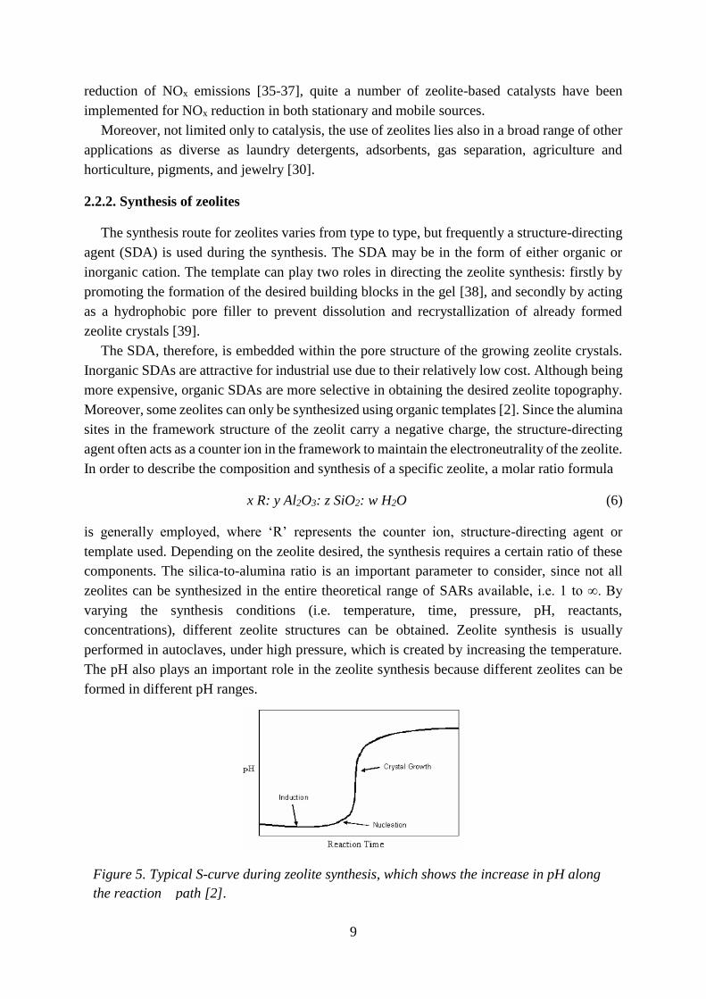
Figure 5. Typical S-curve during zeolite synthesis, which shows the increase in pH along
the reaction path [2].

10
Typically, throughout the zeolite synthesis process the pH increases as the reaction proceeds.
This is caused by the incorporation of the cations into the zeolite framework and the residual
hydroxyl ions, which are left in the synthesis solution. The typical S-curve of the pH during the
zeolite synthesis is shown in Figure 5.
2.2.3. Zeolite ZSM-5 (MFI)
Zeolite ZSM-5 was first synthesized in 1972 by Argauer and Landolt. The acronym ZSM-5
stands for Zeolite Socony Mobil–5 and hence the framework type MFI is derived from ZSM-
5 (five)) [40]. The ZSM-5 structure consists of several pentasil units composed of eight five-
membered rings with Al or Si atoms as the vertices, which are bonded with an O between each
vertex. The pentasil units are connected together by oxygen bridges to form pentasil chains.
Corrugated sheets with 10-ring holes are formed by the interconnection of pentasil chains by
oxygen bridges. In turn, each 10-ring hole has Al or Si as vertices with an O bonded between
each vertex. Each corrugated sheet is connected by oxygen bridges to form a structure with
straight 10-ring channels running parallel to the corrugations and sinusoidal 10-ring channels
perpendicular to the sheets. The pore size of the channels running parallel with the corrugations
is 5.5 Å. The silica-to-alumina ratio ranges from 10 to infinity. The MFI framework structure
is shown in Figure 6a.
2.2.4. Zeolite SSZ-13 (CHA)
Zeolite SSZ-13 was first synthesized by Stacey I. Zones in 1985 [41]. The acronym SSZ-13
stands for Standard Oil Synthetic Zeolite-13 [42]. Zeolite SSZ-13 has the chabazite (CHA)
framework structure, which is a member of a family of zeolites known as the ABC-6 family.
The common feature for all members of this family is that they consist of layers of six–rings or
double six-rings, arranged in a hexagonal array, interconnected by tilted four-rings [43]. Thanks
to this arrangement, the large CHA cavities, which are accessible through a three-dimensional
8-membered ring pore system, are formed. The pore openings for SSZ-13 are 3.6×3.6 Å. The
CHA framework can be constructed at various Si/Al ratios ranging from 1 to infinity. However,
the practically used Cu-SSZ-13 catalysts for SCR most often have Si/Al ratios between 6 and
18 [43, 44]. The CHA framework structure is shown in Figure 6b.
2.2.5. Zeolite Beta (*BEA)
Zeolite Beta is an old zeolite discovered by Mobil, even before the "ZSM" naming sequence
started. As the name implies, it was the second in the earlier sequence. Zeolite beta is disordered
in the c-direction, so the well-defined layers are stacked more or less randomly. For the reason
that no ordered material has been synthesized yet, the three-letter code is preceded by an asterisk
to indicate that the framework type is an idealized end member of a series. [54] units are joined
to one another via 4-rings to form layers with saddle-shaped 12-rings. Adjacent layers are
related to one another by a 90° rotation, either clockwise or counter-clockwise. This rotation in
different directions brings disorder to the structure. However, not depending on the stacking
sequence, a 3-dimensional 12-ring channel system is formed with the pore openings 7.5×7.5 Å.

11
Figure 6. MFI (a), CHA (b) and *BEA (c) framework structures. Adapted from ZEOMICS,
[46].
Therefore, for catalytic applications the stacking sequence is normally not important, unless
one wants to exploit the chirality of the channels in some way [45]. The silica-to-alumina
ratio of zeolite beta ranges from 5 to infinity. The *BEA framework structure is shown in
Figure 6c.
2.2.6. Functionalization of zeolites
Often for the catalytic purposes zeolites must be used in ion-exchanged form. There are some
methods described in the open literature to introduce metals into the zeolite framework. In this
section the most common methods will be discussed.
1) Aqueous ion exchange (AIE) is the most common method for preparing metal-exchanged
zeolites. In this approach, the zeolite in H- or NH4-form is added to an aqueous metal salt
solution under constant stirring in inert atmosphere or air. After a certain time the mixture is
filtered and the precipitate washed. These steps are usually repeated several times.
However, sometimes it can be hard to make use of the full ion-exchange capacity of the
zeolite due to several factors. For zeolites with high silica-to-alumina mole ratio, the ion-
exchange can be limited by the low alumina content in the zeolite framework, as the number of
ion positions that can be utilized are few. Furthermore, for zeolites with narrow channels and/or
for large and multivalent ions to be introduced, steric hindrance may limit the ion-exchange. In
this connection, most of the transition metal cations are strongly solvated [47] and thus
surrounded with hydration shells that enhance the steric hindrance of the solvated cation to
enter narrow channels of the zeolite framework. Especially for iron, it has been reported [48]
that complete ion-exchange is difficult due to limited diffusion of the hydrated cation into the
zeolite pores, which instead results in increased tendency of iron to form iron oxide particles
that might block the pores [13].
2) Chemical vapor deposition (CVD) is known to be an efficient method to achieve high
metal loadings. A metal salt with high vapor pressure, such as FeCl3, GaCl3, ZnCl2, or MoCl5,

12
sublimates into the channels of the zeolite in H-form at elevated temperatures. In the case of
using chlorides, the catalyst has to be washed thoroughly after the exchange process to remove
chlorine residuals and carefully calcined in order to avoid formation of metal oxide particles
[13, 49, 50].
3) Incipient wetness impregnation (WI) is relatively simple and thus has high potential for
industrial implementation. In this method, the zeolite in H- or NH4-form is just saturated with
a precise volume of the metal salt solution that contains all the amount of the metal precursor
that is to be introduced into the zeolite channels. This procedure is followed by drying, where
the solvent evaporates from the zeolite pores, while the metal species remain adsorbed inside
[21, 51].
4) Solid-state ion exchange (SSIE) is also an easy method to apply on an industrial scale.
Typically the conventional SSIE involves two steps, viz., physical mixing of the zeolite in H-
or NH4-form with a metal salt by grinding or ball milling and calcination of the mixture at about
700-800°C for several hours. The high temperature provides the energy required to decompose
and convert the metal salt into a volatile metal species that can migrate into the micropores of
the zeolite [49, 52, 53]. The main disadvantage of the conventional SSIE method is the need of
high temperatures, which can lead to partial or even complete destruction of the zeolite
framework structure.
5) Solid-state ion-exchange facilitated by NH3 and NO ([NH3+NO]-SSIE) is an alternative
low-temperature solid-state route for ion-exchange recently reported by Shwan et al. [54]. In
contrast to the conventional SSIE method that requires high temperatures, the authors show that
copper-exchanged zeolites can be prepared by exposing a physical mixture of the copper oxide
and zeolite to NH3 and/or NO already at 250°C. In the presence of NH3, copper becomes mobile
at low temperatures owing to the formation of [CuI(NH3)x]+ (x ≥ 2) complexes. By adding NO
during the NH3 treatment, the rate of migration of Cu into the zeolite structure is enhanced and
therefore NO most likely assists the reduction of Cu(II) in CuO to Cu(I), which in turn forms
the mobile [CuI(NH3)x]+ complexes. Again, the [NH3+NO]-SSIE method involves only two
operation steps in absence of an aqueous medium, whilst considerably lower temperatures can
be used as compared to conventional SSIE in air.

13
Chapter 3
Experimental methods
3.1. Catalyst preparation
3.1.1. Zeolite synthesis
The zeolite synthesis from different points of view has been studied in this thesis. To start
with, all the zeolites with the CHA framework structure used in this work were synthesized via
hydrothermal synthesis using N,N,N-trimethyl-1-adamantanimonium hydroxide as the
structure-directing agent (papers II-VI). Moreover, it was further shown that the synthesis of
zeolites with CHA framework structure can be successfully performed both in hydroxide
(papers II, III and VI) and fluoride media (papers IV and V). In paper VI it was also
specifically shown that using boron oxide as a source of boron, instead of aluminum hydroxide
as a source of aluminum, leads to the formation of a boron-substituted zeolite with CHA
framework structure, which possesses interesting acidic properties.
3.1.2. Functionalization of ZSM-5, SSZ-13 and BEA
Several different methods for zeolite ion-exchange have been used in this thesis, in order to
study how the method of ion-exchange influences the activity for selective catalytic reduction
of NOx with ammonia. In paper I the functionalization of the H-ZSM-5 (SAR 40, AkzoNobel)
sample with iron was performed by incipient wetness impregnation using iron ions with
different valence (II and III) as precursors and different solvents (methanol and 50 wt.%
methanol in water), and conventional aqueous ion-exchange using Fe(II) as precursor. Further,
the following studies (papers II-V) were mainly based on the results from the previous one as
the starting point for choice of the method of functionalization. In paper II Cu-SSZ-13 (CHA)
was prepared by aqueous ion-exchange for the reason that AIE was shown to lead to the highest
NH3-SCR activity among the studied samples in paper I. However, in papers III and V the
solid-state ion-exchange method was used, in order to avoid solvation effects creating
difficulties for performing proper aqueous ion-exchange for small-pore zeolites. In paper IV,
the functionalization of H-BEA (SAR 38, Zeolyst International) with iron was performed using
incipient wetness impregnation since in the previously reported studies on Fe-BEA prepared in
our group this route was used [55, 56]. However, for the functionalization of H-BEA, Fe-BEA
and H-CHA with copper we used the modified solid-state ion-exchange method where the ion-
exchange is facilitated by NH3 and NO ([NH3+NO]-SSIE), owing to the recently reported high
efficiency of this method [54].

14
3.1.3. Sample preparation for catalytic testing
In paper I the prepared Fe-ZSM-5 samples were washcoated onto cordierite monolith
substrates (Corning, 400 cpsi, 188 channels, L = 20 mm, d = 21 mm). The procedure for
washcoating is described in details in paper I. In Figure 7 monolithic substrates coated with
Fe-ZSM-5 are shown.
In papers II-IV the catalysts were tested in flow reactor experiments in powder form, with
the certain size of the particles between 300-365 µm, in order to avoid a large pressure drop. In
order to get this fraction, the original powder sample was first pressed into a tablet, where after
the tablet was crushed and the fraction of 300-365 µm was collected between the sieves having
opening of the corresponding diameters.
3.2. Continuous flow reactor system
In this thesis two different reactor setups were used. In paper I the monolith reactor system
was used. This setup is intended for experiments with washcoated monolith catalysts. In papers
II-IV the powder reactor system was used, which is used for experiments with powder bed
catalysts.
3.2.1. Monolith reactor system.
The monolith reactor system is schematically shown in Figure 8 and consists of a horizontal
quartz tube (L=800 mm, d=22 mm) equipped with an insulated metal coil for resistive heating.
The inlet gas and catalyst temperature were measured by two individual thermocouples placed
10 mm in front of the catalyst and in the middle of the catalyst, respectively. The inlet gas
temperature was controlled with a PID regulator (Eurotherm). The gas mixing system consists
of separate mass flow controllers (Bronkhorst Hi-Tech) for NO, NH3, O2 and Ar. Water was
added separately to the reactor system via a controlled evaporator mixer system (CEM,
Bronkhorst Hi-Tech). The composition of the gas phase was analyzed by FTIR spectrometry
(MKS 2000 FTIR spectrometer). The temperature programmed NH3-SCR experiments were
performed in the standard SCR conditions of NH3:NO ratio 1:1 (400 ppm both), 8% O2, 0 or
5% of water, and Ar as balance. The total gas flow was kept constant at 3,500 ml/min
corresponding to a space velocity (GHSV) of 27,600 h-1.
Figure 7. Cordierite monolith substrates coated with Fe-ZSM-5.

15
3.2.2. Powder reactor system
The powder reactor system is schematically shown in Figure 9 and represents a continuous
gas flow reactor system, consisting of a vertically placed quartz tube (L=260 mm, d=4 mm)
equipped with an insulated metal coil for resistive heating. The catalytic bed temperature was
measured by a type K thermocouple and controlled by a PID regulator (Eurotherm). A quartz
bed (h=70 mm) was placed first, and the catalytic bed (h=7 mm) was placed on the top of the
quartz bed. The gas mixing system consists of separate mass flow controllers (Bronkhorst Hi-
Tech) for NO, NH3, O2 and Ar. Water was added separately to the reactor system via a
controlled evaporator mixer system (CEM, Bronkhorst Hi-Tech). The inlet of the gas/water
mixture to the reactor was placed 150 mm below the quartz bed. The composition of the gas
phase was continuously analyzed by FTIR spectrometry (MKS 2030 FTIR spectrometer).
Figure 8. Schematics of the monolith reactor system. The flow of the incoming gases is
regulated by separate mass-flow controllers. The composition of the effluent stream is
analyzed with a Fourier transform infrared spectrometer.
Figure 9. Schematics of the powder reactor system. The flow of the incoming gases is
regulated by separate mass-flow controllers. The composition of the effluent stream is
analyzed with a Fourier transform infrared spectrometer.

16
The temperature programmed NH3-SCR experiments were performed in the standard SCR
conditions of NH3:NO ratio 1:1 (400 ppm both), 8% O2, 0 or 5% of water, and Ar as balance
whereby the sample temperature was increased stepwise from 150 to 500 °C with the interval
25-50 °C and kept constant for a time enough to reach a steady-state regime. The heating rate
between the temperature steps was 20 °C/min, and the temperature did not exceed the set-point
by more than 5 °C before stabilization at each step. The total gas flow was kept constant at 300
ml/min, which corresponds to a space velocity (GHSV) of 200,000 h−1.
3.3. Sample characterization
3.3.1. X-ray diffraction
The structure of any non-amorphous material can be defined by regular, repeating planes of
atoms forming a crystal lattice. A monochromatic X-ray beam, which is directed to such
crystalline materials, interacts with these planes of atoms, whereby the beam is partly
transmitted, partly absorbed, partly refracted and scattered, and partly diffracted. Depending on
the type of atoms in the crystal lattice and their arrangement, the X-rays are diffracted in
different ways [57]. Hence, the diffraction pattern can be used to determine the structure of a
specific crystalline material. This technique is called X-ray diffraction (XRD).
Bragg's Law is applied to calculate the distances between the planes of the atoms in the
sample:
n · λ = 2d · sinθ (6)
where n is the order of the diffracted beam and is always an integer, λ is the wavelength of the
incident X-ray beam, d is the distance between adjacent planes of atoms, and θ is the angle of
incidence of the X-ray beam. From the Bragg's Law one can calculate the d-spacings. The
characteristic set of d-spacings generated by X-rays of a specific wavelength give a unique
"fingerprint" of the studied material, and by comparison the results of the measurement with
standard reference patterns one can identify a material given.
For high-symmetry crystal systems the Rietveld refinement method can be used to solve the
crystal structure from diffraction patterns. Both the line positions and intensities are interpreted
by assigning each peak a Gaussian shape so that an overall line profile can be calculated.
Usually, one starts with a trial structure, which gradually is modified by changing the atomic
positions until the best fit is obtained.
3.3.2. Scanning electron microscopy
Scanning electron microscopy (SEM) uses a focused electron beam to create an image of the
sample and achieves a resolution down to the nanometer scale [58, 59].
The electron beam is created by an electron gun and focused onto the sample via a system
of magnetic lenses. When the electrons hit the sample, a number of different interactions occur.
Some electrons do not interact at all, or are just scattered a relatively small angle from the initial
17
beam path. Electrons which are generated as an ionization product by the incoming electron
beam are called secondary electrons. They are used in SEM to map the surface structure of the
sample. Using the secondary electrons for SEM imaging one can obtain an image which shows
the structure of the sampled surface but it does not contain further information about the
chemical composition of the sample. The contrast of SEM images does not indicate an absolute
height but a relative height compared to the surrounding area. The backscattered electrons are
electrons which are reflected due to inelastic scattering with atoms of the sample. The scattering
cross section increases with the atomic number. This characteristic can be used to map areas
with different chemical compositions; hence heavy elements will appear brighter than light
elements.
The interaction of the electron beam with the atoms in the sample also causes excitation of
atoms. This results in the radiation of characteristic X-rays by the different specimen atoms.
The energy-dispersive X-ray spectroscopy (EDS) analyses this characteristic X-rays to
determine the general chemical composition of a given area and can also be used to map the
distribution of individual elements.
3.3.3. Transmission electron microscopy
Transmission electron microscopy (TEM) is analogous to optical microscopy however with
electromagnetic instead of optic lenses. In a TEM an electron beam with high energy and
intensity is created and passed through a condenser before hitting the sample. The condenser
produces parallel rays which are focused on the sample. The electrons transmitted through the
sample give a projection of the samples mass which is magnified by the electron optics to
produce a so-called bright field image. Electrons from the diffracted electron beams are used to
form a so-called dark field image.
Scanning transmission electron microscopy (STEM) is based on the principle of TEM.
However, by scanning a focused beam of electrons across the sample in a raster pattern a virtual
image is built. The rastering of the beam across the sample makes the STEM suitable for
analysis techniques such as mapping by energy-dispersive X-ray spectroscopy (EDS) and
electron energy loss spectroscopy (EELS). These signals can be obtained simultaneously,
allowing direct correlation of image and quantitative data.
3.3.4. X-ray photoelectron spectroscopy
X-ray photoelectron spectroscopy (XPS) can give valuable information about the surface of
a material [2, 59]. XPS spectra are obtained by irradiating the material with a monochromatic
X-ray beam while simultaneously measuring the kinetic energy and number of photoelectrons,
which are emitted from the top (0 to ~1 μm) layers of the sample, under ultra-high vacuum
(UHV) conditions.
XPS can generally be used to measure the elemental composition of the surface, empirical
formula of pure materials, elements that contaminate the surface, chemical or electronic state
of each element in the surface, and uniformity of elemental composition across the top surface.
The energy of X-rays with a particular wavelength is known. Hence, the binding energy of each
of the emitted electrons can be determined from the energy conservation law:

18
Ek = hν – (Eb + φ), (7)
where Ek is the kinetic energy of the photoelectron, h is Planck’s constant, ν is the frequency of
the exciting radiation, Eb is the binding energy of the photoelectron with respect to the Fermi
level of the sample, and φ is the work function of the spectrometer (constant for the spectrometer
given).
A typical XPS spectrum is a plot of the number of electrons detected (i.e. intensity) versus
the binding energy of these electrons. Each element gives a characteristic set of XPS peaks at
characteristic binding energy values. These characteristic peaks correspond to the electron
configuration of the electrons within the atoms, e.g., 1s, 2s, 2p, 3s, etc. The number of detected
electrons in each peak is proportional to the amount of the element within the area irradiated.
3.3.5. Temperature programmed desorption of ammonia
Temperature programmed desorption (TPD) is a procedure used to examine the desorption
of a probe gas from a material [60]. The technique involves exposing the sample to the probe
gas to be adsorbed until saturation, followed by heating the sample and simultaneously
detecting the amount of desorbed probe gas by any available technique, for instance Fourier
transform infrared spectroscopy (FTIR) or mass spectrometry (MS). As the temperature is
increased, the absorbed species will achieve sufficiently high energy to desorb and then will be
detected. This results in one or several desorption peaks in the gas concentration versus time
plot. The temperature of the peak maxima provides information on the binding energies of the
bound species.
In this thesis temperature programmed desorption of ammonia (NH3-TPD) was performed
to study the adsorption strength and the number of available sites for ammonia adsorption on
the surface of the samples studied.
3.3.6. Nitrogen sorption
Nitrogen adsorption is used to measure the surface area and pore volume of a material. Here
the physisorption of nitrogen molecules on the material is measured at a constant temperature
over a range of pressures to form an adsorption isotherm. By measuring both the adsorption and
desorption isotherm for the material given, one can determine the surface area, pore volume,
and pore size distribution of the material [2, 61]. Information about the pore structure of the
material can be concluded already from the isotherm type. The IUPAC classifies six different
forms of adsorption isotherms [4]. This classification is based on the different pore dimensions
and adsorption capacities of the materials. Examples of the different adsorption isotherms are
shown in Figure 10. An adsorption isotherm of type I shows the typical sorption behavior of
microporous materials. At low relative pressure a steep increase of adsorption of the adsorbate
can be seen. This reflects the filling of micropores. Afterwards, when the surface is entirely
covered with the adsorbate, the isotherm proceeds in a horizontal plateau. Type II describes a
system with multilayer adsorption after reaching the monomolecular adsorbate layer at a certain
point, up to the condensation taking place at p/p0=1.

19
Materials without relative large pores (mesopores) show total reversibility during desorption of
the adsorbate (i.e. types I, II, and III). However, mesopores cause a hysteresis between the
adsorption and desorption isotherms (types IV and V). Types III and V show an increase of the
adsorption at higher relative pressures due to weak adsorbate-adsorbent interactions. Type VI
shows the gradual formation of individual adsorbate layers, which stem from a multimodal pore
distribution.
In general, data for the microporous materials is obtained at low pressures (P/P0 ≤ 0.2),
whereas the mesoporous region is located at pressures between P/P0 ~ 0.2-0.8 [2]. In order to
calculate the specific surface area of materials, the BET method is frequently applied [62].
However, in the BET method some assumptions are made, which, strictly speaking, are not
compatible with the microporous materials. However, although the surface area obtained by
applying the BET method for adsorption isotherms on microporous solids does hardly reflect
the true internal surface area, it still can be used for empirical comparison of results [61].
3.3.7. Inductively coupled plasma-atomic emission spectrometry
Inductively coupled plasma-atomic emission spectrometry (ICP-AES) is widely regarded as
the most versatile technique for quantitative analysis within chemistry [63]. Using this method
one can monitor up to 50 elements simultaneously for minor- and trace- levels. First, the sample
must be dissolved in, for instance, aqua regia, where after the solution is pumped to the
spectrometer to become atomized with argon into a hot plasma. The plasma produces
temperatures about 7000 °C, which enable excitation of the outer-shell electrons of the elements
in the sample. The sample is excited, emitting light wavelengths characteristic of its elements.
A mirror reflects the light through the entrance slit of the spectrometer onto a grating separating
the element wavelengths onto photomultiplier detectors. When the excited electrons return to
the ground state, photons of light with an energy characteristic of the element are emitted.
Because the sample usually contains a mixture of elements, a spectra of wavelengths is emitted
simultaneously. The spectrometer uses a grating to disperse the light, separating the particular
element emissions and directing each to a photomultiplier tube detector. The intensity of the
Figure 10. The six major adsorption isotherm classifications according to IUPAC [4].

20
light is directly proportional to the concentration of the element. Special software is used to
convert the electronic signal from the photomultiplier tubes into concentrations.
3.3.8. X-ray fluorescence
X-ray fluorescence (XRF) is the emission of characteristic "secondary" (or fluorescent) X-
rays from a material that has been excited by bombarding with high-energy X-rays. This
technique is widely used for elemental and chemical analysis [64]. The analysis of major and
trace elements by X-ray fluorescence is made possible by the behavior of atoms when they
interact with radiation. So, when materials are excited with X-rays, they become ionized. The
atoms in the sample absorb X-ray energy by ionizing, ejecting electrons from the lower (usually
K and L) energy levels, where after the ejected electrons are replaced by electrons from outer
orbitals with higher energy. This is accompanied by releasing of energy, due to the decreased
binding energy of the electron in the inner orbital compared with an outer one. The emitted
radiation has lower energy than the primary incident X-rays and is named fluorescent radiation.
The energy of the emitted photon is characteristic of a transition between specific electron
orbitals in a particular element. Thanks to this, the resulting fluorescent X-rays can be used to
detect the abundances of elements in the sample [65].
3.3.9. Ultraviolet-visible light spectroscopy
Ultraviolet/Visible spectroscopy (UV-Vis) is used to observe electronic transitions between
molecular orbitals [2]. In this technique the sample is exposed to high-energy electromagnetic
radiation and a detector is used to measure the absorbance at different wavelengths of light. For
measurements of UV-Vis spectra for solid samples an integrating sphere is used in order to
collect the scattered light from the solid samples and direct it into the detector. The Kubelka-
Munk equation can be used to convert the obtained UV-Vis spectrum from transmittance or
absorbance units into Kubelka-Munk units, which is a more accurate representation of solid
samples due to their scattering tendency. The Kubelka-Munk equation is as follows [2]:
F(R∞)=K
S=
(1−R∞)2
2R∞
, (9)
where K is the adsorption coefficient, S is the scattering coefficient, and R∞ is the diffuse
reflectance of the sample when the layer is of infinite thickness.
3.3.10. Nuclear magnetic resonance spectroscopy
Nuclear magnetic resonance (NMR) is a physical phenomenon in which nuclei in a magnetic
field absorb and re-emit electromagnetic radiation. This energy is at a specific resonance
frequency dependent on the strength of the magnetic field and the magnetic properties of the
isotope of the atoms. NMR allows the observation of specific quantum mechanical magnetic
properties of the atomic nucleus.
Solid-state NMR (SSNMR) spectroscopy is a kind of NMR spectroscopy, characterized by
the presence of anisotropic (directionally dependent) interactions. A spin interacts with

21
a magnetic or an electric field. Spatial proximity and/or a chemical bond between
two atoms can give rise to interactions between nuclei. In general, these interactions are
orientation dependent. In media with no or little mobility (e.g. crystals, powders, large
membrane vesicles, molecular aggregates), anisotropic interactions have a substantial influence
on the behavior of a system of nuclear spins. In contrast, in a classical liquid-state NMR
experiment, Brownian motion leads to an averaging of anisotropic interactions. In such cases,
these interactions can be neglected on the time-scale of the NMR experiment.
3.3.11. Fourier transform infrared spectroscopy
Fourier transform infrared spectroscopy is used as part of the reactor setups in this thesis to
detect gas molecules in the outlet of the reactor, as well as diffuse reflectance infrared Fourier
transform spectroscopy is used as a separate characterization technique.
Molecules or solid lattices vibrate when gaining energy because of absorption of photons or
by scattering of photons, electrons or neutrons. Infrared spectroscopy is the most common form
of vibrational spectroscopy and falls into three categories, where the vibration frequency of
molecules which lays in the range 200-4000 cm-1 is the one used in this work. The type of bond
and the masses of the atoms in the molecule are the properties which affect the energy difference
between the vibrational states, where the vibrational frequencies increase with increasing bond
strength and with decreasing mass of the vibrating atoms. Molecules vibrate due to absorption
of photons only if the dipole moment of the molecule changes during the vibration. Molecules
without a changing dipole moment (e.g. N2, O2, and H2) cannot be detected using IR
spectroscopy. By irradiating a sample with infrared radiation one obtains a spectrum over the
photons that are not absorbed by the sample as a function of photon energy, given as
wavenumber or frequency.
Several forms of infrared spectroscopy exist, where one of the most common techniques is
diffuse reflectance infrared Fourier transformed spectroscopy (DRIFTS), which is used to
identify adsorbed species on the surface of a sample. Diffusely scattered radiation is collected
by parabolic mirrors and makes it possible to qualitatively measure the vibrational modes of
the adsorbed species on the surface. The technique is possible to perform in-situ which provides
time-resolved information about changes in surface species caused by changes in reaction
conditions.
In infrared spectroscopy electrons in bonds between atoms are excited by electromagnetic
radiation that provides enough energy for transition between vibrational states. This technique
takes advantage of the fact that molecules absorb radiation at specific frequencies characteristic
of their molecular structure [2]. Therefore one can differentiate between the various gas phase
molecules by the wavelength of light that they adsorb. The excitation of these molecules is
performed by using of an IR beam and a monochromator, which separates the IR radiation
according to wavelength so that the entire IR wavelength region can be scanned.

22

23
Chapter 4
Results and discussion
4.1. Zeolite synthesis
4.1.1. Impact of amount of template used for the zeolite synthesis
In general, for the synthesis of SSZ-13 (CHA) the SDA based on N,N,N-trimethyl-1-
adamantanimonium cation-containing compounds (most often, hydroxide or iodide) has been
shown superior and prevails to be used in relatively high concentrations [22, 31, 66-68]. This
SDA is however expensive and thus, to improve the synthesis economy and facilitate
commercialization of the SSZ-13 zeolite, reducing the amount of SDA during the zeolite
synthesis would be desirable [69].
In paper II zeolite SSZ-13 was synthesized based on the method reported by Zones [31, 41].
However, two important changes of the synthesis route were made, i.e. the use of 25 % lower
amount of the structure-directing agent N,N,N-trimethyl-1-adamantanimonium hydroxide and
increased synthesis time.
The calculated yield was 65 % of the SSZ-13 based on TO2. It is just 9 % lower than yield
of the product obtained by Zones [31], notwithstanding the use of 25 % lower amount of SDA
in the present study. This clearly shows that the synthesis of SSZ-13 can significantly be
improved, in order to achieve higher relative yield of the zeolite (based on the ratio between the
mass of the final product and the mass of the used SDA). The possibility to further optimize the
parameters of the synthesis has also been investigated. It was found that it is possible to prepare
SSZ-13 in 6 days using 15% less amount of SDA that was used in the original receipt by Zones.
Moreover, we also prepared SSZ-13 in 14 days using 25% less amount of SDA than from the
original receipt.
4.1.2. Boron incorporation into the zeolite framework structure
In paper VI the possibility of zeolite framework T-atom substitution (using substitution of
Al with B as an example) was studied and discussed. It was shown that using the same molar
composition in the preparation batch and the same temperature conditions as for the synthesis
of SSZ-13, based on it is possible to form a zeolite also having the CHA framework structure
but with of Si and B as T-atoms.

24
The evidence for incorporation of boron into the tetrahedra is based on SEM imaging, X-ray
diffraction data, and 11B NMR spectroscopy. First, scanning electron microscopy showed the
typical cubic-shaped morphology for the chabazite structure. Furthermore, the powder X-ray
diffractogram showed only peak reflections characteristic for the CHA framework structure.
No clearly pronounced additional peaks were found. Rietveld refinement of the high-resolution
X-ray diffractogram revealed unit cell parameters a and b for the B-CHA sample equal to 13.45
and 14.66 Å, respectively. These parameters are smaller than for normal corresponding
siliceous-based chabazite (i.e. a=13.68 and b=14.77 Å [46]). This is in accordance with
different ionic radii of tetrahedrally cooridated boron (0.11 Å) compared to silicon (0.26 Å).
The 11B MAS NMR spectrum of the as-synthesized B-CHA sample revealed mainly two
narrow and sharp peaks at -3.1 and -3.9 ppm (Figure 11). These peaks are characteristic for BO4
sites within a crystalline framework based on their shift and small quadrupolar coupling
interaction. The broad pattern at about 20 ppm indicates some BO3 sites also being present in
the sample.
The nitrogen adsorption isotherm shows the typical shape for microporous materials where
at low relative pressure, when micropores are refilled, a steep increase of the isotherm can be
seen, however when the surface is fully covered with the adsorbate, the isotherm proceeds in a
horizontal plateau. The measured BET surface area for the B-CHA sample was determined as
533 m2/g, and the measured pore volume was determined as 0.24 ml/g. These values of the
measured BET surface area and pore volume of B-CHA are lower in comparison with the ones
of Al-CHA (611 m2/g and 0.29 ml/g, respectively, [13]). Finally, the determined silicon-to-
boron ratio from ICP-AES analysis was equal to 25 because of the usual difficulties of
incorporating boron beside silicon and obtaining a boron-containing zeolite with silicon-to-
boron ratio below 10 [70].
It is well-known that the acid strength of a zeolite depends mainly on the type of heteroatom
associated with the acid site and secondarily on the topology and the silica-to-metal oxide ratio
[70]. Hence, one would expect the acidity of the B-CHA sample to be lower than of the Al-
Figure 11. 11B magic angle spinning nuclear magnetic resonance spectrum of the
synthesized B-CHA sample.

25
CHA sample. In order to study that, NH3-TPD experiments were performed using
microcalorimetry. An exotherm was recorded when the sample was exposed to NH3. The
maximum of the exotherm was 2.6 mW which was reached almost simultaneously as NH3 could
be observed in the gas outlet. The magnitude of the heat signal corresponds to an average heat
of adsorption of -72 kJ/mol. This value is lower than -114 kJ/mol for Al-CHA [71] indicating
lower acidity of the B-CHA sample compared to Al-CHA.
Modifying the zeolite acidity is in particular interesting for controlling ammonia adsorption
in the applications in which too strong acidity negatively influences the catalytic reaction route,
e.g. by poisoning by the adsorption of the basic reactant and/or product, as well as for some
adsorption processes [72, 73].
Unfortunately, the ion-exchange capacity of the B-CHA zeolite prepared in Paper VI is
limited since the amount of boron tetrahedra in the zeolite structure is low. For example, for the
synthesized B-CHA sample the maximum level of ion-exchange with copper that could be
reached was about 1%. However, for the most active copper-exchanged zeolites in NH3-SCR
normally the ion-exchange level should be at least higher than 2-3%, and here one can find
some room for improvement. However, since the flexibility in the possible range of silica-to-
alumina ratios that can be obtained under fluoride conditions is generally higher than under
hydroxide conditions, synthesis of B-CHA zeolite in fluoride medium might lead to lower
silicon-to-boron ratio and help to overcome the limitations of low ion-exchange capacity.
4.2. Effect of method of functionalization
In paper I the effect of method of functionalization has been proven to play an important
role for the NH3-SCR reaction over different Fe-ZSM-5 (MFI) samples prepared by incipient
wetness impregnation using iron ions with different valence (II and III) as precursors and
different solvents (methanol and 50 wt.% methanol in water), and conventional aqueous ion
exchange using Fe (II) as precursor.
In papers II-V we used different methods for ion-exchange in each separate study. First we
started with the aqueous ion-exchange to obtain Cu-SSZ-13 (CHA) as AIE has led to the highest
NH3-SCR activity among the Fe-ZSM-5 samples in the paper I. However, because of the
difficulties with aqueous ion-exchange for small-pore zeolites, such as steric hindrance of the
solvated multivalent cations to enter narrow zeolite channels solid-state ion-exchange the
solvation effect is avoided, was used in papers III and V. In paper IV the modified solid state
ion-exchange method where ion-exchange is facilitated by NH3 and NO ([NH3+NO]-SSIE),
was used, owing to the reported recently high efficiency of this method.
In Figure 12 the NOx conversion during NH3-SCR for H-ZSM and the different Fe-ZSM-5
samples prepared by incipient wetness impregnation using Fe(NO3)3 as iron precursor and
either methanol or 50 wt% methanol in water as solvent (Fe-Z1 and Fe-Z2 respectively), and
conventional aqueous ion-exchange using FeCl2 as iron precursor (Fe-Z3) is shown.
It can be concluded that the method of functionalization plays an important role for the NH3-
SCR activity, since the catalytic activity varies to a large extent for the different samples. The
H-ZSM-5 sample shows just negligible activity for NH3-SCR. The highest activity among the

26
studied catalysts is shown by the Fe-Z3 sample, which was prepared by aqueous ion-exchange
using Fe (II) salt as precursor. The impregnated samples show lower activity, and presence of
water in the solution for wetness impregnation is beneficial for NH3-SCR activity (Fe-Z2
sample prepared by wetness impregnation in 50 wt.% methanol in water), while the Fe-Z1
sample, which is impregnated in presence methanol only, shows much lower NH3-SCR activity.
The low NH3-SCR activity for the Fe-Z1 sample is caused by high NH3 oxidation activity
for this sample (see Figure 13). Over this sample, ammonia is consumed mainly by reaction
with O2 rather than by reaction with NO according to the NH3-SCR reaction.
Figure 13. NH3 conversion during NH3 oxidation (cooling ramps from 500 to 150 °C) in 400
ppm NH3, 8% O2, 5% H2O, Ar (balance), GHSV=27,600 h-1 over the H-ZSM-5 and the prepared
Fe-ZSM-5 samples.
Figure 12. NOx conversion during NH3-SCR (cooling ramps from 500 to 150 °C) in 400 ppm
NO, 400 ppm NH3, 8% O2, 5% H2O, Ar (balance), GHSV=27,600 h-1 over the H-ZSM-5 and
the Fe-ZSM-5 samples prepared by incipient wetness impregnation using Fe(NO3)3 as iron
precursor and either methanol (Fe-Z1) or 50 wt% methanol in water (Fe-Z2) as solvent, and
conventional aqueous ion-exchange using FeCl2 as iron precursor (Fe-Z3).

27
Figure 14. Deconvoluted Fe 2p3/2 X-ray photoelectron spectra for the prepared Fe-ZSM-5
samples. Experimental data (black dots), Gaussian fit Fe2+ (pink line), Gaussian fit for Fe3+
(green line), sum of the fitted Fe2+ and Fe3+ components (blue line), and baseline for the
Gaussian peaks (red line).
Further, XPS analysis was performed in order to study what types of species are responsible for
NH3-SCR and for the NH3 oxidation reaction. The peak deconvolution results (see Figure 14
and Table 1) and comparison of these results with the catalytic activity results indicate that Fe2+
species promote the NH3-SCR reaction, which Fe3+ species rather promote the NH3 oxidation
reaction.
Table 1. Relative amount of Fe2+ and Fe3+ in the prepared samples.
Sample
Fe2+, %
(B.E. 709.9 eV)
Fe3+, %
(B.E. 711.1 eV)
Fe-Z1 30 70
Fe-Z2 49 51
Fe-Z3 53 47
In paper IV studies of copper-exchange of SSZ-13 also revealed an important role of the
method of preparation. In Figure 15 NOx conversion profiles during NH3-SCR over the copper-
exchanged chabazite samples (with copper loading 2-4%) prepared by different routes are
shown. The Cu-CHA samples prepared by SSIE show lower activity than the sample prepared
by AIE, and the most active catalysts are the samples prepared by [NH3+NO]-SSIE. However,
it should be noted that although the low-temperature activity for the Cu-CHA sample prepared
by AEI is higher than for the Cu-CHA sample prepared by SSIE, at higher temperatures the
activity of the former declines, due to presence of extra-framework copper oxide clusters which
likely are formed due to the steric hindrance effect during aqueous ion-exchange and
responsible for the side reaction of NH3 oxidation. Due to the same reason, the high-temperature
activity for almost all other samples declines. However, for the 2 wt.% Cu-CHA sample
prepared by [NH3+NO]-SSIE and for the 2.7 wt.% Cu-CHA sample prepared by SSIE the NOx

28
conversion does not decline at these temperatures. Most likely, it is because the amount of CuO
in the original mixture is just enough for almost all the copper species to be introduced into the
zeolite structure, and no extra-framework copper oxides clusters were formed. This leads us to
the conclusion that the most suitable method for copper-exchange of SSZ-13 would be
[NH3+NO]-SSIE and one should aim to have about 3% Cu, in order to achieve higher low-
temperature activity without deterioration of the SCR activity at high temperatures.
However, two of the most interesting questions are why the [NH3+NO]-SSIE method results
in the preparation of the most active catalyst and what type of copper species are responsible
for such high activity?
In paper V the SSIE and [NH3+NO]-SSIE ion-exchanged Cu-CHA samples were
characterized by DRIFTS using, in particular, NO as probe molecule, with the aim to get
insights into the location and oxidation state of the Cu species in the zeolite micropores. In
Figure 16 in situ DRIFT spectra of the SSIE and [NH3+NO]-SSIE ion-exchanged Cu-CHA
samples are shown during exposure to NO at 20 °C. NO can be used as a probe molecule for
both Cu2+ and Cu+ species. The absorption peak centered at 2150 cm-1 is assigned to NO+ bound
to Cu+ after autoreduction of Cu2+ species by NO [74]. The peaks in the range of 1890-1949
cm-1 correspond to NO bound to Cu2+ species [74-76] while the peaks at 1808 cm-1 are
associated with NO bound to Cu+ species [74]. The relative peak intensities change with
increasing NO exposure. Likely, this is owing to both kinetic effects during adsorption of NO
and multiple chemical reactions that can take place upon NO adsorption on the copper sites
altering their oxidation state. Therefore, it is most feasible to perform an estimation of the
fraction of the Cu+ and Cu2+ species present in the samples after a short time of NO exposure
as displayed in Table 2.
Figure 15. NOx conversion profiles during NH3-SCR over the Cu-CHA samples prepared by
different ion-exchange routes. The temperature programmed NH3-SCR experiments were
performed using standard SCR conditions, 400 ppm NO, 400 ppm NH3, 8% O2, 5% of water,
and Ar as balance whereby the sample temperature was increased stepwise from 150 to 500
°C with the interval 25-50 °C and kept constant for a time enough to reach a steady-state
regime.

29
Figure 16. In situ DRIFT spectra of the SSIE and [NH3+NO]-SSIE ion-exchanged Cu-CHA
samples during exposure to NO at 20 °C. The red color corresponds to the highest, and blue to
the lowest intensities.
Table 2. Estimated fraction of Cu+ and Cu2+ species present in the samples, as derived from
analyzing the NO-DRIFT spectra at 7s of NO exposure.
Method of IE Fraction of Cu+ species Fraction of Cu2+ species
SSIE 0.10 0.90
[NH3+NO]-SSIE 0.35 0.65
The fraction of Cu+ species is observed to be highest (ca. 35%) in the sample prepared using
[NH3+NO]-SSIE while the sample ion-exchanged by SSIE exhibits the lowest fraction of Cu+
species (ca. 10%). Therefore, an increase of the number of Cu+ species is consistent with the
trend of increase in activity for NH3-SCR, and the Cu+ species are most likely key species
providing high NH3-SCR activity.
4.3. Effect of type of exchanged metal on catalytic
performance
4.3.1. Ion-exchange of iron or copper in SSZ-13
Generally copper-exchanged zeolites show higher NH3-SCR activity at lower temperature
and vice versa, iron-exchanged zeolites are more active for NH3-SCR at high temperatures,
while zeolites in proton or sodium form are almost not active [52]. However, since zeolites with
CHA framework structure are zeolites with small pore openings, ion-exchange with iron is
difficult to perform to the full extent and without formation of iron oxide clusters on the surface
and as the result, blocking the pores and promoting NH3 oxidation activity, and hence
deteriorating NH3-SCR activity. It is also noticeable that we observed that the presence of water
influences the activity over copper- and iron-exchanged SSZ-13 differently.

30
In paper II catalytic activity for NH3-SCR over Na-SSZ-13, Cu-SSZ-13 and Fe-SSZ-13
samples, both in presence and absence of water, was studied (see Figure 17). In the absence of
water, the Na-SSZ-13 sample shows minor NOx reduction, reaching the highest conversion of
only 5 % at 500 °C. However, for the iron- and copper-exchanged SSZ-13 samples the NOx
reduction is much higher. For the Cu-SSZ-13 sample, the NOx reduction is particularly high at
low temperatures resulting in almost complete NOx conversion (98 %) at 250-300 °C. The Fe-
SSZ-13 sample shows relatively low NOx reduction at low temperatures (below 300 °C) but at
higher temperatures the NOx reduction increases considerably, reaching 62 % at 500 °C.
The presence of water affects the catalytic behavior. The minor NOx reduction observed for
the Na-SSZ-13 sample in absence of water is suppressed to negligible levels when water is
present. In the case of the Cu-SSZ-13 sample, water suppresses the activity at low temperatures,
with a maximum of 88 % at 300 °C, however at temperatures above 400 °C the activity for NOx
reduction in presence of water is higher than in absence of water. In contrast, the Fe-SSZ-13
sample shows higher activity for NOx reduction in the presence than in the absence of water.
With the present conditions this is valid for all temperatures studied. As a result, the NOx
conversion for the Fe-SSZ-13 sample reaches 75 % at 500 °C. Hence, the presence of water has
a strong positive effect for the NH3-SCR activity over the iron-exchanged sample. It should
also be noticed that a so-called overconsumption of NH3 [77] was observed, especially at high
temperatures (above 300 °C). This is explained by NH3 oxidation (i.e. oxidation of NH3 by O2),
a side reaction occurring at these reaction conditions and manifested especially at high
temperatures.
Figure 17. NH3 and NOx conversion during NH3-SCR in presence (solid lines) and absence
(dashed lines) of water for the following samples: Na-SSZ-13 (black lines with squares), Fe-
SSZ-13 (red lines with circles) and Cu-SSZ-13 (blue lines with the stars). All samples were
exposed to 400 ppm NH3, 400 ppm NO, 0 or 5 % H2O and 8 % O2 in Ar (balance) at 150, 200,
250, 300, 400 and 500 ⁰C for 45 min for each step. GHSV=205,000 h-1.
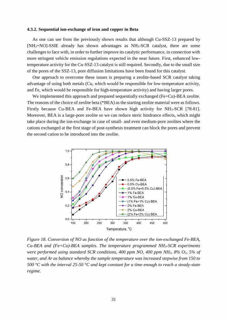
31
4.3.2. Sequential ion-exchange of iron and copper in Beta
As one can see from the previously shown results that although Cu-SSZ-13 prepared by
[NH3+NO]-SSIE already has shown advantages as NH3-SCR catalyst, there are some
challenges to face with, in order to further improve its catalytic performance, in connection with
more stringent vehicle emission regulations expected in the near future. First, enhanced low-
temperature activity for the Cu-SSZ-13 catalyst is still required. Secondly, due to the small size
of the pores of the SSZ-13, pore diffusion limitations have been found for this catalyst.
One approach to overcome these issues is preparing a zeolite-based SCR catalyst taking
advantage of using both metals (Cu, which would be responsible for low-temperature activity,
and Fe, which would be responsible for high-temperature activity) and having larger pores.
We implemented this approach and prepared sequentially exchanged (Fe+Cu)-BEA zeolite.
The reasons of the choice of zeolite beta (*BEA) as the starting zeolite material were as follows.
Firstly because Cu-BEA and Fe-BEA have shown high activity for NH3-SCR [78-81].
Moreover, BEA is a large-pore zeolite so we can reduce steric hindrance effects, which might
take place during the ion-exchange in case of small- and even medium-pore zeolites where the
cations exchanged at the first stage of post-synthesis treatment can block the pores and prevent
the second cation to be introduced into the zeolite.
Figure 18. Conversion of NO as function of the temperature over the ion-exchanged Fe-BEA,
Cu-BEA and (Fe+Cu)-BEA samples. The temperature programmed NH3-SCR experiments
were performed using standard SCR conditions, 400 ppm NO, 400 ppm NH3, 8% O2, 5% of
water, and Ar as balance whereby the sample temperature was increased stepwise from 150 to
500 °C with the interval 25-50 °C and kept constant for a time enough to reach a steady-state
regime.

32
The NH3-SCR activity results for the sequentially exchanged (Fe+Cu)-BEA samples are
shown in Figure 18. One can see that the addition of Cu to the Fe-containing BEA samples has
a considerable beneficial effect on the catalytic properties. All the Fe-exchanged BEA samples
have in general lower SCR activity at lower temperatures and higher SCR activity at higher
temperatures. Vice versa, Cu-BEA samples are in general more active at lower temperatures
but their activity declines at higher temperatures. After adding Cu to Fe-BEA samples using
[NH3+NO]-SSIE, the low-temperature activity increases and the high-temperature activity
decreases, however not as drastically as for the pure Cu-BEA samples. Comparing the NH3-
SCR activity results with the results from the study by Boron et al. where also (Fe+Cu)-BEA
samples were prepared but using simultaneous ion-exchange with both cations [4], the NO
conversion at 150 °C over the (1% Fe+1% Cu)-BEA sample in the present study is higher (28
compared to 13%) despite more than ten times higher GHSV. Moreover, the conversion at high
temperatures is 20-30 percentage higher than for the corresponding sample in the study by
Boron et al. [82]. The (2% Fe+2% Cu)-BEA sample shows even higher activity, with 60 and
90% NO conversion at 150 and 500 °C, respectively. These results indicate that the method of
preparation of sequentially exchanged Fe-Cu-BEA catalysts combining impregnation of zeolite
BEA with iron followed by [NH3+NO]-SSIE with copper, results in highly active catalytic
formulations for NH3-SCR. We also should add that there still might be some room for
improvement of the sequential ion-exchange method, and the catalytic activity can potentially
be improved even further. For instance, we may suppose that varying the method of ion-
exchange and/or order of ion-exchange might result in even higher activity for NH3-SCR.

33
Chapter 5
Conclusions and future outlook The objective of this thesis is to understand how different methods for synthesis and
functionalization of zeolites influence the physicochemical properties of the materials and the
catalytic performance for selective catalytic reduction of nitrogen oxides with ammonia.
Specifically, different routes for synthesis of zeolites with CHA framework structure and
different methods for ion-exchange of zeolites with CHA, MFI and *BEA framework structures
with copper and/or iron have been used.
The results show possibility of optimization of zeolite synthesis route by varying the
concentration of the SDA in the preparation batch, and modifying physicochemical properties
of zeolitic materials, such as acidity, by isomorphous substitution of T-atoms (for example
substitution of aluminum with boron in the chabazite framework structure). Unfortunately, the
ion-exchange capacity of the prepared B-CHA zeolite is limited due to the low amount of boron
in the zeolite framework, and this needs to be improved. This presumably can be performed by
synthesis of B-CHA in fluoride medium instead of hydroxide medium.
Moreover, the choice of metal for ion-exchange, and method of functionalization were
shown to be of importance for the catalytic and structural properties of the functionalized
zeolites. Among the methods for functionalization, ([NH3+NO]-SSIE generally leads to the
most active catalytic formulations compared to the other methods of ion-exchange (SSIE, AEI
and WI) studied. Moreover, zeolite functionalization with transition metal ions was shown to
significantly enhance the catalytic activity. Cu-exchanged zeolites show high NH3-SCR activity
over a broad temperature range, especially at low temperatures, while Fe-exchanged zeolites
are more active for NH3-SCR at high temperatures. Although the strategy of preparation of
highly active NH3-SCR catalysts was shown, there are some improvements to be made, in order
to further improve the catalytic performance, in connection with more stringent vehicle
emission regulations expected in the near future. First, enhanced low-temperature activity is
desirable. In order to achieve this, one can try adding a promoter and hence lowering the
Cu2+/Cu+ redox cycling barrier.
Additionally, a method of sequential ion-exchange with both iron and copper leading to
NH3-SCR catalysts that are highly active over a broad temperature range was developed. These
results indicate that the method of preparation of sequentially exchanged Fe-Cu-BEA catalysts
combining impregnation of zeolite beta with iron followed by [NH3+NO]-SSIE with copper,
results in highly active catalytic formulations for NH3-SCR. However, there still might be some
room for improvement of the sequential ion-exchange method, and the catalytic activity can
potentially be improved even further. For instance, one may suppose that varying the method
of ion-exchange and/or order of ion-exchange might result in higher activity for NH3-SCR.

34
Furthermore, it was found that Fe2+ species rather than Fe3+ species, and similar, Cu+ species
rather than Cu2+ species are beneficial for NOx reduction in NH3-SCR. This fact might help in
later research studies to further improve the NH3-SCR catalytic performance.
It should be added that for the small-pore zeolites, pore diffusion limitations may affect the
catalytic function. One approach to suppress such limitations is to reduce the particle size,
another approach might be in preparation of hierarchical micro-mesoporous materials where
the zeolite crystals can be coated with thin film of mesoporous materials. The way to obtain
such materials is well-known from the literature [83] and can be easily applied to high-silica-
containing zeolites, including SSZ-13. And last but not least, alternative types of zeolites can
be found, the synthesis approach can be developed, e.g. using computational approach [84],
with the purpose of using these materials as NH3-SCR catalysts.

35
Acknowledgements
This work has been performed at the Competence Centre for Catalysis (KCK), which is
financially supported by Chalmers University of Technology, the Swedish Energy Agency and
the member companies: AB Volvo, ECAPS AB, Haldor Topsøe A/S, Scania CV AB and Volvo
Car Corporation AB.
I would like also to acknowledge the following people.
Professor Magnus Skoglundh, my examiner and main supervisor. First of all, thank you
for giving me an opportunity to do my PhD at KCK and secondly, for all your support,
inspiration and freedom in research you were always giving to me throughout my PhD.
Associate Professor Per-Anders Carlsson and Professor Hanna Härelind, my co-
supervisors. Thank you for your constant great support and for always being available for
discussions!
Dr. Peter N. R. Vennestrøm and Dr. Arkady Kustov (Haldor Topsøe A/S), thank you
for those nice and fruitful meetings with you and your availability to discuss all the scientific
topics, especially about zeolites.
My co-authors Dr. Hannes Kannisto, Dr. Anna Clemens and Dr. Soran Shwan, Dr.
Lars Nordstierna, Dr. Alexander Idström and MSc Lorenz Bock for your help with the lab
work and all our scientific discussions we had.
Adam Arvidsson and Peter Velin, thank you for the help with cover figure and Swedish
text, respectively.
Ann Jakobsson, thank you for your help with all the administrative issues.
All the previous and current colleagues and friends from KCK (especially the old KCK
gang!), thank you for your friendship and all the great time we had during both working hours
and afterworks.
All the colleagues and friends from TYK, thank you for creating a great atmosphere in the
fika room and during our leisure time.
Marika and Peter, my former and current office-mates, thank you for creating such a great
working atmosphere in the office!
All my friends, both from Russia and from Sweden, thank you for all your love, support and
fun we had together.
My wonderful family, thank you for all the encouragement and support over the years and
the patience that I was always away.

36

37
References
[1] http://www.ecoscore.be/, Why and how do we take into account NOx emissions from diesel
cars under real-life traffic conditions?
[2] D.W. Fickel, Investigating the high-temperature chemistry of zeolites: dehydrogenation of
zeolites and NH3-SCR of copper-exchanged small-pore zeolites, University of Delaware, 2010.
[3] Beñat Pereda-Ayo and Juan R. González-Velasco (2013). NOx Storage and Reduction for
Diesel Engine Exhaust Aftertreatment, Diesel Engine - Combustion, Emissions and Condition
Monitoring, Dr. Saiful Bari (Ed.). Available from: http://www.intechopen.com/books/diesel-
engine-combustion-emissions-and-condition-monitoring/nox-storage-and-reduction-for-
diesel-engine-exhaust-aftertreatment.
[4] T. Horikawa, D.D. Do, D. Nicholson, Capillary condensation of adsorbates in porous
materials, Adv Colloid Interfac, 169 (2011) 40-58.
[5] W.A. Majewski, H. Jääskeläinen, Environmental Effects of Emissions,
http://www.dieselnet.com/tech/env_effect.php
[6] G.T. Miller, Living in the Enviroment - Principles, Connections and Solutions, 15th ed.,
2007, pp. 485-486.
[7] E.S.J. Lox, Automotive Exhaust Treatment in: G. Ertl, H. Knözinger, F. Schüth, J.
Weitkamp (Eds.), Handbook of heterogeneous catalysis, Second, completely revised and
enlarged edition, Vol. 1, Wiley-VCH Verlag GmbH& Co. KGaA, Weinheim, Germany, 2008,
pp. 2274-2275.
[8] T.V. Johnson, Diesel Emissions in Review, SAE Int J of Engines, 4 (2011) 143-157.
[9] J. Dings, Mind the Gap! Why official car fuel economy figures don’t match up to reality,
Transport and Environment, http://www.transportenvironment.org/, 2013.
[10] J. Leake, H. Summers, Diesel cars built to foil test for toxic fumes, Sunday Times,
September 21, 2014.
[11] J. Poliscanova, Realistic real-world driving emissions tests: the last chance for diesel cars?,
http://www.transportenvironment.org/, 2015.
[12] R. Burch, Knowledge and Know‐How in Emission Control for Mobile Applications, Catal
Reviews, 46 (2004) 271-334.
[13] S. Brandenberger, O. Krocher, A. Tissler, R. Althoff, The State of the Art in Selective
Catalytic Reduction of NOx by Ammonia Using Metal-Exchanged Zeolite Catalysts, Catal Rev,
50 (2008) 492-531.
[14] Green Universe, http://greenuniverse007.wordpress.com/.
[15] M. Eichelbaum, R.J. Farrauto, M.J. Castaldi, The impact of urea on the performance of
metal exchanged zeolites for the selective catalytic reduction of NOx: Part I. Pyrolysis and
hydrolysis of urea over zeolite catalysts, Appl Catal B: Environm, 97 (2010) 90-97.
[16] P.L.T. Gabrielsson, Urea-SCR in automotive applications, Top Catal, 28 (2004) 177-184.
[17] I. Ellmers, R.P. Vélez, U. Bentrup, A. Brückner, W. Grünert, Oxidation and selective
reduction of NO over Fe-ZSM-5 – How related are these reactions?, J of Catal, 311 (2014) 199-
211.

38
[18] T.V.W. Janssens, H. Falsig, L.F. Lundegaard, P.N.R. Vennestrøm, S.B. Rasmussen, P.G.
Moses, F. Giordanino, E. Borfecchia, K.A. Lomachenko, C. Lamberti, S. Bordiga, A. Godiksen,
S. Mossin, P. Beato, A Consistent Reaction Scheme for the Selective Catalytic Reduction of
Nitrogen Oxides with Ammonia, ACS Catal, 5 (2015) 2832-2845.
[19] P. Forzatti, L. Lietti, Recent advances in De-NO(x)ing catalysis for stationary applications,
Heterogen Chem Rev, 3 (1996) 33-51.
[20] P. Forzatti, I. Nova, E. Tronconi, A. Kustov, J.R. Thøgersen, Effect of operating variables
on the enhanced SCR reaction over a commercial V2O5–WO3/TiO2 catalyst for stationary
applications, Catal Today, 184 (2012) 153-159.
[21] A. Shishkin, P.-A. Carlsson, H. Härelind, M. Skoglundh, Effect of Preparation Procedure
on the Catalytic Properties of Fe-ZSM-5 as SCR Catalyst, Top Catal, 56 (2013) 567-575.
[22] J.H. Kwak, R.G. Tonkyn, D.H. Kim, J. Szanyi, C.H.F. Peden, Excellent activity and
selectivity of Cu-SSZ-13 in the selective catalytic reduction of NOx with NH3, J of Catal, 275
(2010) 187-190.
[23] C. Ciardelli, I. Nova, E. Tronconi, D. Chatterjee, T. Burkhardt, M. Weibel, SCR of for
diesel exhausts aftertreatment: role of in catalytic mechanism, unsteady kinetics and monolith
converter modelling, Chem Eng Science, 62 (2007) 5001-5006.
[24] R.Q. Long, R.T. Yang, Temperature-Programmed Desorption/Surface Reaction
(TPD/TPSR) Study of Fe-Exchanged ZSM-5 for Selective Catalytic Reduction of Nitric Oxide
by Ammonia, J of Catal, 198 (2001) 20-28.
[25] J. Eng, C.H. Bartholomew, Kinetic and Mechanistic Study of NOx Reduction by NH3 over
H-Form Zeolites, J of Catal, 171 (1997) 27-44.
[26] Y.G. Bushuev, Zeolity. Komp'uternoe modelirovanie zeolitnykh materialov., Ivanovskij
Gosudarstvennyj Technologicheskij Universitet. - 104 p. , 2011.
[27] C. Baerlocher, L.B. McCusker, D.H. Olson, Atlas of zeolite framework types, 6th revised
edition, Elsevier, 2007, pp. 381-386.
[28] P. Payra, P.K. Dutta Zeolites: A Primer in: S. Auerbach, K. A. Carrado, P. K. Dutta (ed.)
Handbook of Zeolite Science and Technology , Marcel Dekker Inc.: New York. , 2003, pp. 12-
30.
[29] G. Engelhardt, Solid State NMR Spectroscopy Applied to Zeolites in: H. van Bekkum, E.
M. Flanigen, J. C. Jansen Introduction to Zeolite Science and Practice, Elsevier, New York,
2001, pp. 285-315.
[30] M.E. Davis, Zeolites and molecular sieves: not just ordinary catalysts, Industrial &
Engineering Chemistry Research, 30 (1991) 1675-1683.
[31] International Zeolite Association web-page, http://www.iza-online.org (last time accessed:
2016, January, 8).
[32] T. Maesen, Chapter 1 The zeolite scene — an overview, in: J. Čejka, H.v. Bekkum, A.
Corma, F. Schüth (Eds.) Studies in Surface Science and Catalysis, Elsevier, 2007, pp. 1-12.
[33] B. Yilmaz, U. Müller, Catalytic Applications of Zeolites in Chemical Industry, Top Catal,
52 (June 2009) 888-895.

39
[34] A. Cuperman, A. Kustov, L. Kustov, Further Steps of Zeolites towards Industrial
Applications: a Short-Range Outlook, in: L. Kustov (Ed.) Zeolites and Zeolite-like Materials:
Quo Vadis?, Moscow State University, 2013, pp. 391-461.
[35] M.V. Twigg, Catalytic control of emissions from cars, Catal Today, 163 (2011) 33-41.
[36] X. Auvray, W.P. Partridge, J.-S. Choi, J.A. Pihl, A. Yezerets, K. Kamasamudram, N.W.
Currier, L. Olsson, Local ammonia storage and ammonia inhibition in a monolithic copper-beta
zeolite SCR catalyst, Appl Catal B: Environm, 126 (2012) 144-152.
[37] M. Colombo, I. Nova, E. Tronconi, V. Schmeißer, B. Bandl-Konrad, L. Zimmermann,
NO/NO2/N2O–NH3-SCR reactions over a commercial Fe-zeolite catalyst for diesel exhaust
aftertreatment: Intrinsic kinetics and monolith converter modelling, Appl Catal B: Environm,
111–112 (2012) 106-118.
[38] G. Boxhoorn, P.H.G. O. Sudmeijer, J.C.S. van Rasteren, Chem Communications, 1416
(1983).
[39] J. Keijsper, M. Mackay, J.v.d. Berg, A.G.T.G. Kortbeek, M.F.M. Post, Prep. KNCV Katal.
Symp., 39 (1986).
[40] L. McCusker, C. Baerlocher Zeolite Structures in: Zeolites and Ordered Mesoporous
Materials: Progress and Prospects : the 1st FEZA School on Zeolites, Prague, Czech Republic,
2005, pp. 41-64.
[41] S.I. Zones, US4544538 A, Zeolite SSZ-13 and its method of preparation, USA, 1985.
[42] http://izasc.ethz.ch/fmi/xsl/IZA-SC/Zeolite_names.htm
[43] R.W. Broach, Zeolite Type and Structures in: S. Kulprathipanja (Ed.), Zeolites in Industrial
Separation and Catalysis, WILEY-VCH Verlag GmbH & Co., Weinheim, 2010, pp. 42-44.
[44] F. Gao, J.H. Kwak, J. Szanyi, C.H.F. Peden, Current Understanding of Cu-Exchanged
Chabazite Molecular Sieves for Use as Commercial Diesel Engine DeNOx Catalysts, Top Catal,
56 (2013) 1441-1459.
[45] L.B. McCusker, C. Baerlocher, Zeolite structures, in: J. Čejka, H.v. Bekkum (Eds.) Studies
in Surface Science and Catalysis, Elsevier, 2005, pp. 41-64.
[46] E.L. First, C.E. Gounaris, J. Wei, C.A. Floudas, Computational characterization of zeolite
porous networks: an automated approach, Phys Chem Chem Phys, 13 (2011) 17339-17358.
[47] A.V. Kucherov, A.A. Slinkin, Solid-state reaction as a way to transition metal cation
introduction into high-silica zeolites, J of Molec Catal, 90 (1994) 323-354.
[48] I. Melián-Cabrera, S. Espinosa, J.C. Groen, B. v/d Linden, F. Kapteijn, J.A. Moulijn,
Utilizing full-exchange capacity of zeolites by alkaline leaching: Preparation of Fe-ZSM5 and
application in N2O decomposition, J of Catal, 238 (2006) 250-259.
[49] H. Sjövall, L. Olsson, E. Fridell, R.J. Blint, Selective catalytic reduction of NOx with NH3
over Cu-ZSM-5—The effect of changing the gas composition, Appl Catal B: Environm, 64
(2006) 180-188.
[50] L.J. Lobree, I.-C. Hwang, J.A. Reimer, A.T. Bell, Investigations of the State of Fe in H–
ZSM-5, J of Catal, 186 (1999) 242-253.
[51] S. Shwan, R. Nedyalkova, J. Jansson, J. Korsgren, L. Olsson, M. Skoglundh, Influence of
Hydrothermal Ageing on NH3-SCR Over Fe-BEA-Inhibition of NH3-SCR by Ammonia, Top
Catal, 56 (2013) 80-88.

40
[52] S. Brandenberger, O. Kröcher, A. Tissler, R. Althoff, The State of the Art in Selective
Catalytic Reduction of NOx by Ammonia Using Metal‐Exchanged Zeolite Catalysts, Catal
Reviews, 50 (2008) 492-531.
[53] R.Q. Long, R.T. Yang, Fe-ZSM-5 for Selective Catalytic Reduction of NO with NH3: A
Comparative Study of Different Preparation Techniques, Catal Letters, 74 (2001) 201-205.
[54] S. Shwan, M. Skoglundh, L.F. Lundegaard, R.R. Tiruvalam, T.V.W. Janssens, A.
Carlsson, P.N.R. Vennestrøm, Solid-State Ion-Exchange of Copper into Zeolites Facilitated by
Ammonia at Low Temperature, ACS Catal, 5 (2015) 16-19.
[55] S. Shwan, E. Adams, J. Jansson, M. Skoglundh, Effect of Thermal Ageing on the Nature
of Iron Species in Fe-BEA, Catal Letters, 143 (2013) 43-48.
[56] S. Shwan, J. Jansson, J. Korsgren, L. Olsson, M. Skoglundh, Kinetic modeling of H-BEA
and Fe-BEA as NH3-SCR catalysts—Effect of hydrothermal treatment, Catal Today, 197
(2012) 24-37.
[57] C. Suryanarayana, M.G. Norton, X-Ray Diffraction: A Practical Approach, Plenum Press,
New York, 1998, pp. 52-60.
[58] F. Liu, Scanning Electron Microscopy (SEM) and Focused Ion Beam (FIB), lecture notes
distributed in Advanced Analysis Methods TIF110 at the Chalmers University of Technology,
Gothenburg, 2013.
[59] I. Chorkendorff, J.W. Niemantsverdriet, Concepts of Modern Catalysis and Kinetics,
WILEY-VCH Verlag GmbH & Co. KGaA, Weinheim, 2003, pp. 134-139.
[60] V. Rakić, L. Damjanović, Temperature-Programmed Desorption (TPD) Methods, in: A.
Auroux (Ed.) Calorimetry and Thermal Methods in Catalysis, Springer Berlin Heidelberg,
2013, pp. 131-174.
[61] M. Thommes, Chapter 15 Textural characterization of zeolites and ordered mesoporous
materials by physical adsorption, in: J. Čejka, H.v. Bekkum, A. Corma, F. Schüth (Eds.) Studies
in Surface Science and Catalysis, Elsevier2007, pp. 495-XIII.
[62] J. Rouquerol, P. Llewellyn, F. Rouquerol, Is the BET equation applicable to microporous
adsorbents?, in: P.L. Llewellyn, F. Rodriquez-Reinoso, J. Rouqerol, N. Seaton (Eds.) Studies
in Surface Science and Catalysis, Elsevier2007, pp. 49-56.
[63] Central Mineral and Environmental Resources Science Center, ICP-AES Technique
Description, minerals.cr.usgs.gov/gips/na/5process.html
[64] B. Beckhoff, B. Kanngießer, N. Langhoff, R. Wedell, H. Wolff, Handbook of Practical X-
Ray Fluorescence Analysis, Springer, 2006, pp. 1-31.
[65] R. Shankar, ED - XRF & WD - XRF, http://aviabi2001.blogspot.se/2009/03/ed-xrf-wd-
xtf.html.
[66] D.W. Fickel, E. D’Addio, J.A. Lauterbach, R.F. Lobo, The ammonia selective catalytic
reduction activity of copper-exchanged small-pore zeolites, Appl Catal B: Environm, 102
(2011) 441-448.
[67] L. Wu, V. Degirmenci, P.C.M.M. Magusin, N.J.H.G.M. Lousberg, E.J.M. Hensen,
Mesoporous SSZ-13 zeolite prepared by a dual-template method with improved performance
in the methanol-to-olefins reaction, J of Catal, 298 (2013) 27-40.
41
[68] F. Gao, E.D. Walter, E.M. Karp, J. Luo, R.G. Tonkyn, J.H. Kwak, J. Szanyi, C.H.F. Peden,
Structure–activity relationships in NH3-SCR over Cu-SSZ-13 as probed by reaction kinetics
and EPR studies, J of Catal, 300 (2013) 20-29.
[69] Z. Liu, Y. Wang, Z. Xie, Thoughts on the Future Development of Zeolitic Catalysts from
an Industrial Point of View, Chinese J Catal, 33 (2012) 22-38.
[70] J.-L. Guth, H. Kessler, Synthesis of Aluminosilicate Zeolites and Related Silica-Based
Materials, in: J. Weitkamp, L. Puppe (Eds.) Catalysis and Zeolites, Springer Berlin Heidelberg,
1999, pp. 1-52.
[71] M. Brändle, J. Sauer, Acidity Differences between Inorganic Solids Induced by Their
Framework Structure. A Combined Quantum Mechanics/Molecular Mechanics ab Initio Study
on Zeolites, J of Am Chem Soc, 120 (1998) 1556-1570.
[72] A. Corma, State of the art and future challenges of zeolites as catalysts, J of Catal, 216
(2003) 298-312.
[73] J. Liang, J. Su, Y. Wang, Z. Lin, W. Mu, H. Zheng, R. Zou, F. Liao, J. Lin, CHA-type
zeolites with high boron content: Synthesis, structure and selective adsorption properties,
Micropor and Mesopor Mat, 194 (2014) 97-105.
[74] J. Szanyi, J.H. Kwak, H. Zhu, C.H.F. Peden, Characterization of Cu-SSZ-13 NH3-SCR
catalysts: an in situ FTIR study, Phys Chem Chem Phys, 15 (2013) 2368-2380.
[75] F. Göltl, P. Sautet, I. Hermans, Can Dynamics Be Responsible for the Complex Multipeak
Infrared Spectra of NO Adsorbed to Copper(II) Sites in Zeolites?, Angew Chem Int Ed, 54
(2015) 7799-7804.
[76] R. Zhang, J.-S. McEwen, M. Kollár, F. Gao, Y. Wang, J. Szanyi, C.H.F. Peden, NO
Chemisorption on Cu/SSZ-13: A Comparative Study from Infrared Spectroscopy and DFT
Calculations, ACS Catal, 4 (2014) 4093-4105.
[77] R. Nedyalkova, K. Kamasamudram, N.W. Currier, J. Li, A. Yezerets, L. Olsson,
Experimental evidence of the mechanism behind NH3 overconsumption during SCR over Fe-
zeolites, J of Catal, 299 (2013) 101-108.
[78] S. Shwan, L. Olsson, M. Skoglundh, J. Jansson, Kinetic modeling of Fe-BEA as NH3-SCR
catalyst—effect of phosphorous, AIChE J, 61 (2015) 215-223.
[79] N. Wilken, K. Wijayanti, K. Kamasamudram, N.W. Currier, R. Vedaiyan, A. Yezerets, L.
Olsson, Mechanistic investigation of hydrothermal aging of Cu-Beta for ammonia SCR, Appl
Catal B: Environm, 111–112 (2012) 58-66.
[80] A. Frey, S. Mert, J. Due-Hansen, R. Fehrmann, C. Christensen, Fe-BEA Zeolite Catalysts
for NH3-SCR of NOx, Catal Letters, 130 (2009) 1-8.
[81] O. Mihai, C.R. Widyastuti, S. Andonova, K. Kamasamudram, J. Li, S.Y. Joshi, N.W.
Currier, A. Yezerets, L. Olsson, The effect of Cu-loading on different reactions involved in
NH3-SCR over Cu-BEA catalysts, J of Catal, 311 (2014) 170-181.
[82] P. Boroń, L. Chmielarz, S. Dzwigaj, Influence of Cu on the catalytic activity of FeBEA
zeolites in SCR of NO with NH3, Appl Catal B: Environm, 168–169 (2015) 377-384.
[83] I.I. Ivanova, E.E. Knyazeva, Micro-mesoporous materials obtained by zeolite
recrystallization: synthesis, characterization and catalytic applications, Chem Soc Rev, 42
(2013) 3671-3688.

42
[84] D.W. Lewis, Chapter 8 - Template-host interaction and template design, in:
C.R.A.C.A.v.S. Smit (Ed.) Computer Modelling of Microporous Materials, Academic Press,
London, 2004, pp. 243-265.

Paper I
Effect of preparation procedure on the structural and catalytic properties of Fe-ZSM-5
as SCR catalyst
A. Shishkin, P.-A. Carlsson, H. Härelind and M. Skoglundh
Topics in Catalysis, 56 (2013) 567-575.


Paper II
Synthesis and functionalization of SSZ-13 as NH3-SCR catalyst
A. Shishkin, H. Kannisto, P.-A. Carlsson, H. Härelind and M. Skoglundh
Catalysis Science and Technology, 4 (2014) 3917-3926.


Paper III
Reaction-driven ion-exchange of copper into zeolite SSZ-13
A. Clemens, A. Shishkin, P.-A. Carlsson, M. Skoglundh, F. Martínez-Casado, Z. Matěj,
O. Balmes and H. Härelind
ACS Catalysis, 5 (2015) 6209-6218.


Paper IV
Copper modified CHA and Fe-BEA for improved NH3-SCR activity
Shishkin, S. Shwan, A. Clemens, H. Härelind, P.-A. Carlsson, T. Pingel, E. Olsson and
M. Skoglundh
Manuscript.

Paper V
Probing copper species in solid-state ion-exchanged Cu-CHA by selective chemisorption
of CO and NO
A. Clemens, A. Shishkin, P.-A. Carlsson, M. Skoglundh and H. Härelind
Manuscript.


Paper VI
Direct synthesis of boron-substituted CHA framework structure
A. Shishkin, A. Clemens, F. Martínez-Casado, L. Bock, A. Idström, L. Nordstierna,
H. Härelind, P.-A. Carlsson and M. Skoglundh
Manuscript.