ALDOT - Alabama Department of Transportation · Each 5 07A Wire Rope Abutment Anchor Assembly ... *...
15
ALDOT Pre-cast Standard Bridge Plans Detailing Manual 3/23/15
Transcript of ALDOT - Alabama Department of Transportation · Each 5 07A Wire Rope Abutment Anchor Assembly ... *...

ALDOT
Pre-cast Standard Bridge Plans
Detailing Manual
3/23/15

PURPOSE OF THIS MANUAL
The purpose of this manual is to provide guidance and promote consistency to counties, cities and
consultants in developing bridge contract drawings for the Alabama Department of
Transportation (ALDOT) utilizing ALDOT’s Pre-Cast Standard Drawings. Structural plans must
clearly communicate the design concept and construction requirements for each project.
Exceptions to methods used in detailing and presentation of plans are anticipated based on
specific design requirements.
Detailers shall follow the guidelines in this manual unless the State Bridge Engineer provides
exception approval. It is the detailer’s responsibility to prepare complete plans in accordance with
these guidelines. Competent personnel other than those performing the initial detailing shall make
an independent check of the bridge plans for completeness and accuracy. A copy of the
“checklist” portion of this document shall be completed and submitted with each set of bridge
plans that are to be reviewed by ALDOT Bridge Bureau staff. This requirement applies to all
structures using precast members.
For details not specifically addressed in this document, detailers are encouraged to ask for
example drawings of the most current details used by this Department.
See appendices for example precast bridge sheet drawings.
The ALDOT Bridge Bureau looks forward to working with the various Counties, Cities and
Municipalities for the State of Alabama.
Sincerely,
John F. Black, PE
ALDOT Bridge Engineer
2

TABLE OF CONTENTS
General Guidelines --------------------------------------------------------------------3 - 4
Order of Bridge Sheets --------------------------------------------------------------- 4
Precast Bridge --------------------------------------------------------------------------5 – 10
Appendix A -----------------------------------------------------------------------------11-12
Appendix B -----------------------------------------------------------------------------13-15
GENERAL GUIDELINES
TEXT
Typical text on all sheets shall measure 1/8’’ in height on a full size bridge sheet. Detail titles,
section labels, etc. shall measure 3/16’’ in height on a full size bridge sheet. (1.5 times typical text
height for CADD purposes). Text shall be all capital letters except when referencing Standard
Specifications. Line spacing in paragraphs shall equal text height. Text height can be calculated
by multiplying sheet scale by 0.125 or matching text height to “bridge sheet no.” in the title box.
Text shall be a weight of 1 for typical text and a weight of 3 for detail titles, section labels, etc. .
LINE WEIGHTS
The following line weights shall be used:
Object lines – 3
Dimension lines – 1
Hidden lines – 0
Extension lines – 1
Terminator – 1
Phantom lines – 2
Underline (detail titles, section labels, etc.) – 3
DIMENSIONING
Spacing between dimension lines with a single line of text shall be 3.5 times text height. Spacing
for a double line of text shall be 5 times text height. Extension line shall extend 2/3 text height
past the final dimension line. Auto dimensioning is not to be used.
3

SHEET BORDER
The ALDOT Bridge Borders are available on the following website,
http://www.dot.state.al.us/brweb/atrip.htm. These Bridge Borders shall be used for all plans
prepared using ALDOT’s Precast Standards. The Bridge Inventory Number (BIN) shall be
shown on all sheets.
GENERAL SHEET GUIDELINES
See Appendix A or Appendix B for Example precast bridge sheet(s).
ORDER OF BRIDGE SHEETS
• Bridge General Elevation Sheet
• Bridge Special Project Drawings (if required)
• Test Boring Record Sheet(s)
4

“BRIDGE GENERAL ELEVATION SHEET” SHEET
1. ESTIMATED QUANTITIES
Quantity, unit, item number and description of each pay item. (Be certain each item of work or
material required has method of payment) Quantity numbers should be right justified and unit
descriptions should be left justified. The following is a partial list of commonly used pay items.
Quantity Unit Item Number Description
Lump Sum 206A Removal of Old Bridge, Station
* Pound 502A Steel Reinforcement
Each 505A Steel Test Pile (HP_x_)
Each 505A Concrete Test Pile (_ " Square)
Each 505B Static Loading Test (Pile Type/Size)
Each 505B Dynamic Loading Test (Pile Type/Size)
Each 505G Pile Points (Type , _")
Linear Feet 505H Pilot Holes
Linear Feet 505M Steel Piling Furnished and Driven (HP _x_)
Linear Feet 505N Concrete Piling Furnished (_" Square)
Linear Feet 505O Concrete Piling Driven (_" Square)
Each 507A Wire Rope Abutment Anchor Assembly
*** Pound 508A Structural Steel
* Cubic Yard 510A Bridge Substructure Concrete, Class A
Each 511A Elastomeric Bearings, Type
Each 512A Precast Concrete Abutment Caps, Wide by
Deep by Long
Each 512B Precast Concrete Intermediate Bent Caps,
_____Wide by _____ Deep by ______Long
Each 512C Precast Concrete Type _ Span Section,
_____Wide by _____ Deep by ______Long
Each 512D Precast Concrete Barrier Rail End Section,
________Long
Each 512D Precast Concrete Barrier Rail Intermediate
Section,_____Long
Each 512E Precast Concrete Abutment Panels, Type __
Each 512F Precast Concrete Wing Panels, Type
Each 512G Precast Concrete Abutment Wing Cap Panels, Type
___
Each 512J Precast Concrete Pedestrian Barrier Rail,
*Quantities are for Pile Encasement (See BGN-1 Note 10)
***Quantity for Sway bracing if required
5

2. QUANTITIES ROUNDING
a) Individual Bridge Sheets
1. Pay Item 502A&B Steel Reinforcement: Round up to nearest ten pounds.
2. Pay Item 508A Structural Steel: Round up to nearest pound.
3. Pay Item 51OA&C Substructure & Superstructure Concrete: Round
up to nearest tenth of yard.
b) Front Sheet Totals
1. Pay Item 502A&B Steel Reinforcement: Round up to
nearest one hundred pounds.
2. Pay Item 508A Structural Steel: Round up to nearest ten pounds.
3. Pay Item 510A&C Substructure & Superstructure Concrete: Round
up to nearest cubic yard.
4. Other:
Pay items with Square Yard: Round up to nearest square yard.
Pay items with Linear Foot: Round up to nearest linear foot.
3. REQUIRED
Description of required superstructure
Description of required abutments
Description of required bents
Standard Bridge Details, Standard Drawing I-131.
Standard Bridge Notes, Standard Drawing BGN-1.
Test Boring Record Sheet reference.
Standard Precast Bridge Drawings (as applicable)
PC-24 Roadway width 24’6” or 28’ Span Length 24’
PC-34-2 Roadway width 24’6” or 28’ Span Length 34’
PC-40 Roadway width 24’6” or 28’ Span Length 40’
PCBR-1(24)
Roadway width 24’6” or 28’ Span Length 34’
PCBR-1(34) Roadway width 24’6” or 28’ Span Length 40’
PCBR-1(40)
Roadway width 24’6” or 28’ Span Length 24’
PCA-2440 Roadway width 24’6” Span Length 24’, 34’or 40’
PCA-2840 Roadway width 28’ Span Length 24’, 34’or 40’
PCA-2840CP Roadway width 28’ Span Length 24’, 34’or 40’
PCAB-3540 Roadway width 35’ Span Length 24’, 34’or 40’
PCB-2440 Roadway width 24’6” Span Length 24’, 34’or 40’ PCB-2840 Roadway width 28’ Span Length 24’, 34’or 40’
PCB-2840-1 Roadway width 28’ Span Length 24’, 34’or 40’ PCB-2840CP Roadway width 28’ Span Length 24’, 34’or 40’
PCP-2400 Roadway width 24’6” Span Length 24’, 34’or 40’
PCP-2400CP Roadway width 24’6” Span Length 24’, 34’or 40’ PCP-2800 Roadway width 28’ Span Length 24’, 34’or 40’
PCP-2800 Roadway width 28’ Span Length 24’, 34’or 40’
6

4. STANDARD BRIDGE NOTES
Reference required notes Standard Drawing BGN-1
Under STANDARD BRIDGE NOTES, provide roadway width (gutter to gutter) with
Barrier Rails . List appropriate BGN-1 notes from current special project drawing.
1
2 HS 20-44
5 ABUTS TONS
BENTS TONS 9 1-A
10
28
29 ( Only if the foundation report is completed by ALDOT. )
5. CONSULTANT CERTIFICATION
The first sheet of the bridge plans should be stamped by the engineer(s) of record and
the following note should be included adjacent to the registered engineer(s) stamp:
I CERTIFY THAT COMPLETE REVIEWS OF THE DESIGNER’S CALCULATIONS,
CONTRACT STRUCTURAL DRAWINGS, APPLICABLE SPECIFICATIONS, AND
SPECIAL PROVISIONS HAVE BEEN MADE BY COMPETENT ENGINEERS OF
THIS ORGANIZATION, AND THAT THESE PLANS ARE ACCURATE,
COMPLETE, AND SUITABLE FOR LETTING.
APPROVED:
(Engineer of Record’s Signature)
REGISTRATION NO.
DATE:
APPROVED:
(Reviewing Engineer’s Signature)
REGISTRATION NO.
DATE:
7
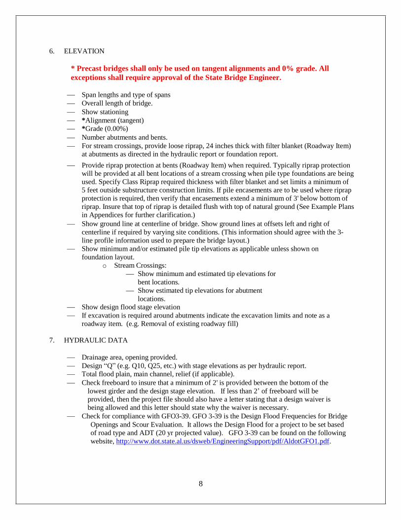
6. ELEVATION
* Precast bridges shall only be used on tangent alignments and 0% grade. All
exceptions shall require approval of the State Bridge Engineer.
Span lengths and type of spans
Overall length of bridge.
Show stationing
*Alignment (tangent)
*Grade (0.00%)
Number abutments and bents.
For stream crossings, provide loose riprap, 24 inches thick with filter blanket (Roadway Item)
at abutments as directed in the hydraulic report or foundation report.
Provide riprap protection at bents (Roadway Item) when required. Typically riprap protection will be provided at all bent locations of a stream crossing when pile type foundations are being
used. Specify Class Riprap required thickness with filter blanket and set limits a minimum of
5 feet outside substructure construction limits. If pile encasements are to be used where riprap
protection is required, then verify that encasements extend a minimum of 3' below bottom of
riprap. Insure that top of riprap is detailed flush with top of natural ground (See Example Plans
in Appendices for further clarification.)
Show ground line at centerline of bridge. Show ground lines at offsets left and right of
centerline if required by varying site conditions. (This information should agree with the 3-
line profile information used to prepare the bridge layout.)
Show minimum and/or estimated pile tip elevations as applicable unless shown on
foundation layout.
o Stream Crossings:
Show minimum and estimated tip elevations for
bent locations.
Show estimated tip elevations for abutment
locations. Show design flood stage elevation
If excavation is required around abutments indicate the excavation limits and note as a
roadway item. (e.g. Removal of existing roadway fill)
7. HYDRAULIC DATA
Drainage area, opening provided.
Design “Q” (e.g. Q10, Q25, etc.) with stage elevations as per hydraulic report.
Total flood plain, main channel, relief (if applicable).
Check freeboard to insure that a minimum of 2' is provided between the bottom of the
lowest girder and the design stage elevation. If less than 2’ of freeboard will be provided, then the project file should also have a letter stating that a design waiver is
being allowed and this letter should state why the waiver is necessary.
Check for compliance with GFO3-39. GFO 3-39 is the Design Flood Frequencies for Bridge
Openings and Scour Evaluation. It allows the Design Flood for a project to be set based
of road type and ADT (20 yr projected value). GFO 3-39 can be found on the following
website, http://www.dot.state.al.us/dsweb/EngineeringSupport/pdf/AldotGFO1.pdf.
8

8. SPECIAL NOTES
Wing piles shall be driven to refusal or 20 feet, whichever is less. The minimal penetration for the
wing piles shall not be less than 10 feet into natural ground. All Abutment Piles, Bent Piles and
Abutment anchor piles shall be installed in accordance with Section 505 of the Standard
Specification.
If piles will be end bearing, provide a note stating that piles shall be driven to refusal.
If piles are not end bearing, then a pay item for test pile(s) and load test(s) (static) will need to be
provided.
If pile bents are being specified include the following note:
Furnishing of all necessary equipment and construction of all sheeting and shoring, cribs,
cofferdams, caissons, de-watering, etc. which may be necessary for the construction of
the pile encasements shall be a subsidiary obligation of pay item 510A, Bridge
Substructure Concrete.
On bridge replacement projects, show substructure conflict note if applicable.
EXAMPLE : IN AREAS WHERE EXISTING SUBSTRUCTURE IS IN CONFLICT WITH
THE NEW FOUNDATION, THE EXISTING FOOTING (INCLUDING PULLING
EXISTING PILES) SHALL BE REMOVED PRIOR TO PLACING THE NEW
FOUNDATION. THIS SHALL BE PAID FOR UNDER PAY ITEM NO. 206A,
``REMOVAL OF OLD BRIDGE, STATION ??+??.??''
Pile encasement shall extend 3’ below the bottom of rip-rap.
If the foundation report performed by a consultant firm, a plan note stating to whom a request for a copy can be sent. i.e. ACCESS TO THE FOUNDATION REPORT AND CORE BORINGS CAN BE ARRANGED BY CONTACTING THE COUNTY/CITY ENGINEER.
The County/City Geotechnical Engineer of Record ( ) shall be responsible for all reviews of
contractor submittals and all field monitoring as required by the Contract Documents.
9
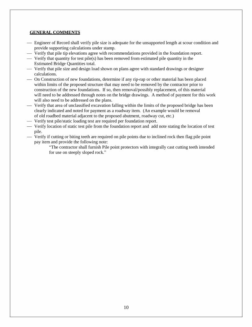
GENERAL COMMENTS
Engineer of Record shall verify pile size is adequate for the unsupported length at scour condition and
provide supporting calculations under stamp.
Verify that pile tip elevations agree with recommendations provided in the foundation report.
Verify that quantity for test pile(s) has been removed from estimated pile quantity in the
Estimated Bridge Quantities total.
Verify that pile size and design load shown on plans agree with standard drawings or designer
calculations.
On Construction of new foundations, determine if any rip-rap or other material has been placed
within limits of the proposed structure that may need to be removed by the contractor prior to
construction of the new foundations. If so, then removal/possibly replacement, of this material
will need to be addressed through notes on the bridge drawings. A method of payment for this work
will also need to be addressed on the plans.
Verify that area of unclassified excavation falling within the limits of the proposed bridge has been
clearly indicated and noted for payment as a roadway item. (An example would be removal
of old roadbed material adjacent to the proposed abutment, roadway cut, etc.)
Verify test pile/static loading test are required per foundation report.
Verify location of static test pile from the foundation report and add note stating the location of test
pile.
Verify if cutting or biting teeth are required on pile points due to inclined rock then flag pile point pay item and provide the following note:
“The contractor shall furnish Pile point protectors with integrally cast cutting teeth intended
for use on steeply sloped rock.”
10

Appendix A
One sheet Precast Example
11

Appendix B
Two sheet Precast Example
13