ALDOT-367 PRODUCTION AND INSPECTION OF … AND INSPECTION OF PRECAST NON-PRESTRESSED AND PRESTRESSED...
53
ALDOT-367-89 REV. 08-19-2015 PAGE 1 of 53 ALDOT-367 PRODUCTION AND INSPECTION OF PRECAST NON-PRESTRESSED AND PRESTRESSED CONCRETE SCOPE The quality control and quality assurance requirements for the production and inspection of precast concrete products are given in this procedure. These requirements shall be followed to insure that the quality of the precast products is acceptable. The requirements in this procedure shall be applicable to the production of precast concrete bridge members. This includes requirements for the production of non-prestressed and pretensioned prestressed structural members. The word "pretensioned" is a term that is designated for a member in which steel prestressing strands are loaded with a tension force prior to having concrete placed to cover the strands and form the required shape of the member. The tension force is released after the concrete has gained sufficient strength so that part of the force remains in the strands and the concrete in which the strands are embedded. This resulting force is a "prestress" that is applied to counteract or balance the stress applied to the member when it is installed in a structure and subjected to loading. This procedure is a supplement to the contract for construction. Where conflicting requirements exist, the requirements given in the contract shall be applicable instead of the requirements given in this procedure. The information in this document is intended principally for the production and inspection of bridge members. It may be used for the production and inspection of other type of precast non- prestressed and pretensioned prestressed concrete products, subject to conformance with applicable specifications.
Transcript of ALDOT-367 PRODUCTION AND INSPECTION OF … AND INSPECTION OF PRECAST NON-PRESTRESSED AND PRESTRESSED...
ALDOT-367-89 REV. 08-19-2015
PAGE 1 of 53
ALDOT-367 PRODUCTION AND INSPECTION OF PRECAST NON-PRESTRESSED
AND PRESTRESSED CONCRETE
SCOPE The quality control and quality assurance requirements for the production and inspection of
precast concrete products are given in this procedure. These requirements shall be followed to insure that the quality of the precast products is acceptable.
The requirements in this procedure shall be applicable to the production of precast concrete bridge members. This includes requirements for the production of non-prestressed and pretensioned prestressed structural members.
The word "pretensioned" is a term that is designated for a member in which steel prestressing strands are loaded with a tension force prior to having concrete placed to cover the strands and form the required shape of the member. The tension force is released after the concrete has gained sufficient strength so that part of the force remains in the strands and the concrete in which the strands are embedded. This resulting force is a "prestress" that is applied to counteract or balance the stress applied to the member when it is installed in a structure and subjected to loading.
This procedure is a supplement to the contract for construction. Where conflicting requirements exist, the requirements given in the contract shall be applicable instead of the requirements given in this procedure.
The information in this document is intended principally for the production and inspection of bridge members. It may be used for the production and inspection of other type of precast non-prestressed and pretensioned prestressed concrete products, subject to conformance with applicable specifications.

ALDOT-367-89 REV. 08-19-2015
PAGE 2 of 53
SECTION 1 PRECAST NON-PRESTRESSED CONCRETE BRIDGE MEMBERS
1 REFERENCE DOCUMENTS
1.1 ALDOT STANDARD SPECIFICATIONS FOR HIGHWAY CONSTRUCTION Requirements for the materials and processes required for the production of precast non-
prestressed concrete are given in the following Sections of the Specifications: (Web link: ALDOT SPECIFICATIONS)
501 Structural Portland Cement Concrete 502 Steel Reinforcement 510 Bridges 512 Precast Non-Prestressed Concrete Bridge Members 801 Coarse Aggregate 802 Fine Aggregates 806 Mineral Admixtures 807 Water 808 Air Entraining Additives 809 Chemical Admixtures for Concrete 815 Cement 830 Concrete Curing Materials 834 Piling Materials 835 Steel reinforcement
1.2 ALDOT PROCEDURES Requirements for the materials and processes required for production of precast non-
prestressed concrete bridge members are given in the following ALDOT Procedures contained in the Testing Manual: (Web link: ALDOT PROCEDURES)
170 Method of Controlling Concrete Operations for Structural Portland Cement Concrete
175 Method for Stockpiling Coarse Aggregate for All Purposes 352 Certification Program for Portland Cement Concrete Producers 355 General Information Concerning Materials, Sources, and Devices with Special
Acceptance Requirements 405 Certification and Qualification Program for Concrete Technicians and Concrete
Laboratories 407 Calibration Verification of Truck Mounted Water Meters 452 Sieve Stability Test for Self-Consolidating Concrete
1.3 BMT FORMS Documentation of the materials and processes required for production of precast non-
prestressed concrete bridge members shall be entered on the following BMT forms: (Web link: ALDOT FORMS)
75 Concrete Mix Design 95 Concrete Plant checklist 110 Concrete Placement Daily Report 122 Concrete Batch Ticket 183 Product Inspection Report 184 Materials and Tests Report 185 Shipping Notice – Precast Non-Prestressed Concrete Bridge Members 209 Self-Consolidating Concrete Placement Daily Report
ALDOT-367-89 REV. 08-19-2015
PAGE 3 of 53
1.4 AASHTO STANDARDS Requirements for the materials and processes required for production of precast non-
prestressed concrete bridge members are given in the following AASHTO Standards:
T 22 Compressive Strength of Cylindrical Concrete Specimens T 23 Making and Curing Concrete Test Specimens in the Field T 24 Obtaining and Testing Drilled Cores and Sawed Beams of Concrete T 119 Slump of Hydraulic Cement Concrete T 121 Density (Unit Weight), Yield, and Air Content (Gravimetric) of Concrete T 152 Air Content of Freshly Mixed Concrete by the Pressure Method T 160 Length Change of Hardened Hydraulic Cement Mortar and Concrete T 197 Time of Setting of Concrete Mixtures by Penetration Resistance T-309 Temperature of Freshly Mixed Portland Cement Concrete M 31 Deformed and Plain Billet Steel Bars for Concrete Reinforcement M 32 Cold Drawn Steel Wire for Concrete Reinforcement M 157 Ready-Mixed Concrete
1.5 ASTM STANDARDS Requirements for the materials and processes required for production of precast non-
prestressed concrete bridge members are given in the following ASTM Standards: C 1611 Standard Test Method for Slump Flow of Self-Consolidating Concrete C 1621 Standard Test Method for Passing Ability of Self-Consolidating Concrete by J-Ring
1.6 ACI STANDARDS Requirements for the materials and processes required for production of precast non-
prestressed concrete bridge members are given in the following ACI Standards:
211.1 Practice for Selecting Proportions for Normal, Heavyweight, and Mass Concrete
1.7 PCI STANDARDS Requirements for the materials and processes required for production of precast non-prestressed concrete bridge members are given in the following PCI Standards:
TM-101 Quality Control Technician/Inspector Level I & II TM-103 Quality Control Personnel Certification Level III MNL-116 Quality Control for Plants and Production of Structural Precast Concrete
Products MNL-135 Tolerance Manual for Precast and Prestressed Concrete Construction
2 INITIAL PLANT QUALIFICATION REQUIREMENTS
2.1 QUALIFICATION SUBMITTAL Producers of precast non-prestressed concrete must be qualified by ALDOT and placed on
List I-10, PRODUCERS OF PRECAST NON-PRESTRESSED AND PRESTRESS CONCRETE BRIDGE MEMBERS, in order to supply precast non-prestressed concrete members to ALDOT projects. Any producer placed on List I-10 will be removed if the producer fails to adhere to the requirements given in this Procedure. Any producer wishing to supply precast non-prestressed concrete bridge members to ALDOT projects shall submit the following to the Concrete Engineer:
ALDOT-367-89 REV. 08-19-2015
PAGE 4 of 53
2.1.1 PLANT CERTIFICATION The producer of precast non-prestressed concrete products shall be certified by
either the Precast/Prestressed Concrete Institute (PCI) Plant Certification Program or the National Precast Concrete Association (NPCA) Plant Certification Program. PCI certification shall be at least Category B1 (Precast Bridge Products).
2.1.2 QUALITY CONTROL PLAN The producer of precast non-prestressed products shall submit a Quality Control
Plan to the Materials and Tests Engineer. The procedures for controlling and monitoring the quality of the precast concrete during production shall be given in this plan. The Quality Control Plan shall identify the plant’s certified Quality Control Technician(s), as defined in Section 3 of this document, and provide proof of certification.
2.1.3 FEES All applicable fees & forms shall be submitted per ALDOT-355.
2.2 PLANT INSPECTION Upon receipt & acceptance of all items listed in Section 2.1, an inspection of the plant
facilities will be scheduled. Areas and items to be inspected will be documented on BMT-210, “Plant Inspection Form for Precast/Prestress Concrete Bridge Member & Pole Producers”. Any deficiencies must be corrected prior to adding the plant to List I-10.
3 PLANT REQUALIFICATION REQUIREMENTS
3.1 ANNUAL RE-QUALIFICATION Producers of precast non-prestressed concrete shall be requalified by ALDOT on an annual
basis in order to remain on List I-10. As part of requalification, the following shall be submitted each December by qualified producers:
Proof of continual maintenance of PCI or NPCA certification. Updated copy of the plant’s Quality Control Plan, including certified technician
certifications. Fees per ALDOT-355.
3.2 PLANT INSPECTION Plants actively producing for ALDOT projects will be inspected continuously throughout
the year during production, as described in the remainder of this procedure. These plants shall only be charged for one fee in December each year.
Plants which have not produced for ALDOT within the previous year shall have an inspection scheduled with ALDOT during December. All other requalification submittals shall be provided to the inspector at that time.
4 PLANT QUALITY CONTROL TECHNICIAN The producer of the precast non-prestressed concrete shall have at least one Quality Control (QC)
technician present on each line of production. The QC technician shall be responsible for all aspects of production from the initial preparations for casting to the shipment of the members. The QC technician shall be responsible for insuring that the materials and workmanship meet the requirements given in the Specifications, shown on the Plans and described in this Procedure.
The QC technician shall be certified as an ALDOT Concrete Technician. This technician shall also be certified as a PCI Level I/II technician.
The QC technician shall be responsible for the following in the sequence of production: Inspection of production facilities and materials prior to concrete placement Inspection of concrete placement and curing of members Inspection of precast products after curing and during handling and storage Inspection of handling and shipping
ALDOT-367-89 REV. 08-19-2015
PAGE 5 of 53
The QC technician shall also be responsible for the following: Enforce compliance with the Quality Control Program Sample materials for testing and prepare sampling documentation Submit materials to be tested to the Bureau of Materials and Tests Be present during production and shipment of precast components Perform quality control tests and measurements Ensure that test equipment is calibrated and maintained Inspect each precast component Ensure that all products are properly cured Maintain a daily production log Ensure that all products are marked in accordance with this procedure Apply stencil on each component with the QC technician DOT Certification Number Ensure that all products are properly stored Fill out, submit, and maintain test report and production documentation Prepare and maintain documentation of sampling, testing and material sources Fill out shipping tickets Ensure that all materials used during production are from ALDOT approved sources
5 ALDOT'S QUALITY ASSURANCE INSPECTOR Quality Assurance (QA) inspection will be performed by a technician assigned by the ALDOT. The
QA inspector will review the work of the producer's QC technician to verify that all of the operations required for the production of precast non-prestressed concrete are being done in accordance with the requirements given in the Specifications, shown on the Plans and described in this Procedure.
The QA inspector will be certified as an ALDOT Concrete Technician and will also be certified as a PCI Level I/II technician.
The QA inspector will review the proposed production operations with the producer's QC inspector prior to production so that there will be no misunderstandings concerning the requirements for production.
The QA inspector shall be responsible for the following:
Perform plant inspections Review the work of the producer's QC technician Place identification on producer's products to signify approval for shipping of precast
non-prestress concrete bridge members
6 ALDOT'S SUPERVISORY PERSONNEL The ALDOT's Quality Assurance (QA) technician will be assisted by supervisory personnel from the
Materials and Tests Bureau. Supervisory personnel will monitor work of the QA inspector and will be responsible for the following:
Process requests for approval of all new material sources Process requests for approval of all new producers of precast non-prestress bridge
components Maintain the approved list of producers Review the producer’s Quality Control plan Review producer's proposals for the repair of damaged members
7 INSPECTION FACILITIES The producer shall provide all facilities for inspection of materials and workmanship at the
fabrication plant. The producer shall provide the QA inspectors access to a work station located inside the plant perimeter. This work station shall meet the following minimum requirements and include the following minimum equipment without extra compensation from the Department:
Facility shall have a watertight roof It shall be Insulated and weather tight
ALDOT-367-89 REV. 08-19-2015
PAGE 6 of 53
Include operational heating and air-conditioning Functional electrical service A desk with a chair File cabinet with lock Functional telephone service Functional fax service
8 SHOP DRAWINGS The ALDOT’s Standard and Special Drawings shall be used as shop drawings required for the
production member. Modifications to the details shown on the drawings may be given in the construction contract and shall be adhered to for the production member.
9 MATERIALS 9.1 TYPE AND QUALITY OF MATERIALS
The type and quality of materials required for precast non-prestressed production shall be in accordance with the requirements given in the Specifications, shown on the Plans and described in this Procedure.
9.2 SUBMITTAL OF CONCRETE MIXTURE DESIGN The producer shall submit a proposal of the proportions of materials for each type of
concrete used for production of precast non-prestressed concrete bridge members. The proposal of the mixture design shall be in accordance with the requirements given in ALDOT-170, the requirements given in Section 512 and the requirements given in this procedure.
Concrete mixes may be designed either by a commercial laboratory or by the production plant laboratory. Commercial or plant laboratories shall meet the requirements given in ALDOT-405.
The producer shall obtain the Material and Tests Engineer's approval of the mixture design prior to using the mixture for production of precast non-prestressed concrete bridge members. The mixture design shall be resubmitted for approval if there are any changes to the type, source or proportions of materials. The re-approval of the mixture design shall be as described in ALDOT-170.
Item 4 of ALDOT-170 shall be amended by the requirement that three cylinders shall be made for testing the compressive strength of the concrete at an age of one day. The 1-day specimens shall be cured the same way that the components are cured for the first 24 hours. The results of the compressive strength testing of the 1-day cylinders shall be plotted on the water-cementitious ratio vs strength curve.
9.3 ADDITIONAL REQUIRED TESTING FOR SCC MIXTURES The design of the SCC shall be in compliance with the requirements given in Item
512.02(c)4. All SCC test specimen molds, air content buckets, and unit weight buckets shall be filled in one continuously poured lift using a suitable container without vibration, rodding, or tapping. The SCC shall be dropped from a height of 6 inches ± 2.0 inches above the top of the mold or bucket into the center of the container, unless otherwise specified. The SCC shall be struck off level with the top of the mold or bucket.
9.3.1 SLUMP FLOW TESTING The filling ability of SCC shall be determined by slump flow testing in
accordance with the requirements of ASTM C 1611. The slump flow test shall be performed using the mold in the inverted position, defined as Filling Procedure B in ASTM C 1621.
9.3.2 PASSING ABILITY TESTING The passing ability of SCC shall be determined by J-Ring testing in accordance
with the requirements of ASTM C 1621. The passing ability test shall be performed using the mold in the inverted position, defined as Filling Procedure B in ASTM C 1621.
ALDOT-367-89 REV. 08-19-2015
PAGE 7 of 53
9.3.3 STABILITY TESTING The Visual Stability Index (VSI) shall be used to assess the stability of SCC for
mixture approval. The VSI shall be assigned in accordance with the requirements of the Appendix of ASTM C 1611.
9.3.4 ROBUSTNESS TESTING Well-proportioned SCC shall be robust to ensure that segregation of the
mixture does not occur during or after placement. Robustness testing shall be performed on a minimum size batch of 3 cubic yards from the concrete producer’s batch plant. No water may be withheld from the minimum batch size of 3 cubic yards. The SCC shall be produced to meet the total air content, slump flow, stability, temperature, and strength requirements as defined in Item 512.02(c)4. A representative sample shall be taken and the unit weight shall be determined in accordance with the requirements given in AASHTO T 121. After completion of the unit weight test, a 2 cubic foot sample shall be taken for further testing. The concrete weight of the 2 cubic foot sample shall be calculated from the unit weight test result. The 2 cubic foot sample shall be added to a buttered rotating-drum mixer and additional water shall be added to the mixture. The additional water shall equal 2 % of the total fine aggregate saturated-surface dry weight in the 2 cubic foot sample. The concrete sample with the added water shall be mixed for 1 minute and then the tests for mixture robustness (Slump Flow and Visual Stability Index) shall be performed. The Slump Flow and VSI tests shall be completed within 5 minutes after completion of mixing with additional water.
9.4 SIZE OF COARSE AGGREGATE The size of coarse aggregate shall not be larger than 1/5 of the narrowest space between
the sides of the forms. The size of the coarse aggregate shall also not be larger than 3/4 of the narrowest clear spacing between individual reinforcing bars or bundles of bars. Coarse aggregate for SCC shall meet the requirements of Item 512.02(c)4.
9.5 CHEMICAL ADMIXTURES Chemical admixtures may be used to increase the slump of the concrete if this is shown
on the approved mixture design. Chemical admixtures may be used to alter the slump flow and stability of self-consolidating concrete if these admixtures are shown on the approved mixture design.
9.6 MINERAL ADMIXTURES Mineral admixtures may be used as part of the cementitious material if this is shown on
the approved mixture design.
9.7 REINFORCING STEEL The certifications for the steel reinforcement shall be submitted to the Materials and
Tests Engineer for review. The certifications shall include the actual test results for each lot of reinforcing steel. Certifications that include typical test results for steel reinforcing in general are unacceptable.
Steel reinforcement will be evaluated for acceptance on certification meeting the requirements given in AASHTO M 31 and could be subject to the procedures given for Independent Assurance Sampling and Testing (IAS&T). (Web link: IAS&T)
9.8 MISCELLANEOUS ITEMS AND ACCESSORIES Sampling and testing of miscellaneous items and accessories shall be done in accordance
with the requirements given in Division 800 for the type of material being furnished.
10 FORMS 10.1 FORM MATERIALS AND CONFIGURATION
Steel side forms and steel or concrete bottom forms shall be used for casting precast non-prestressed concrete bridge members. Forms shall be of sufficient thickness and shall be braced, stiffened and anchored to maintain the correct alignment and to withstand the forces that result from vibratory placement of the concrete.
Keyways, countersunk keys, and other configurations shown on the plans shall be built into the forms. Tops of headers shall be in the same plane as the top of the side forms. The elevation of
ALDOT-367-89 REV. 08-19-2015
PAGE 8 of 53
the tops of the headers and side forms shall be the same on all forms used in the production of a line of the same or similar types of components.
10.2 CLEANING AND ASSEMBLY OF FORMS Forms shall be cleaned before each use. Paint and other protective substances that might
cling to the surface of the member shall be removed from the forms. All joints in the forms shall be smooth and tight to avoid undesirable flaws and blemishes
in the finished member. Leakage of mortar will not be permitted. Joints between the soffit, side forms and headers shall be tight. Joints may be sealed with
gaskets of rubber or other suitable materials. Gasket materials may also be used to provide chamfers. Slots and holes in the forms shall be plugged so that the finished member will be smooth.
The alignment of the forms shall be maintained throughout the casting operation. Form alignment and grade shall be checked each time the forms are set.
Headers and side forms shall be adequately secured to maintain the shape and dimensions of the member within the required tolerances.
10.3 BOND BREAKERS APPLIED TO FORMS Forms shall be treated with a clear non-staining bond breaking agent that partially dries
and leaves a bond breaking film to prevent the concrete member from sticking to the form. The strength of the member is based on the development of uniform bond of the concrete
to all of the reinforcing steel within the member. Bond breaking substances shall be kept from falling on the reinforcing steel to make sure that the concrete will bond adequately to the reinforcing steel.
The bond breaking substance may be applied to the bottom of the form before the reinforcing steel is placed. Special care shall be taken to prevent the bond breaking substance from getting on the reinforcing steel when the steel is being placed into position.
The bond breaking substance shall be applied to the side forms before they are set. Special care must be taken to prevent the bond breaking substance on the side forms from getting on the reinforcing steel during the positioning of the forms. Forms shall not be sprayed with a bond breaking substance after the reinforcing steel has been positioned.
10.4 MULTIPLE FORMS FOR PRODUCTION LINES Each production line shall be equipped with a complete set of forms so that all members
in a casting line can be cast in one operation. Members shall be cast and cured in a continuous operation. The movement of forms from, or within a production line will not be permitted until the concrete reaches the specified 28-day compressive strength.
10.5 INSPECTION OF FORMS PRIOR TO CASTING Forms for casting of precast non-prestressed concrete bridge members shall be inspected
by the QC technician prior to the beginning of casting operations. Documentation of inspection and maintenance records shall be kept on file by the QC technician. The QA inspector will review the QC technician documentation and will verify that all forms meet the requirements given in this procedure or shown on the approved drawings.
11 REINFORCING STEEL Steel reinforcement shall be installed in accordance with the details shown on the plans.
Reinforcement shall be installed within the allowable tolerances for placement. Bar size, bar location, bar spacing, and the spacing in the forms for concrete cover shall be checked by the QC technician prior to placement of concrete.
Tie wires used to fasten the reinforcing steel in place shall be bent away from what will be the exterior of the member to make sure that required protective cover of concrete will be provided when the concrete is placed.
Reinforcing bars that extend out of the member shall be properly positioned and shall have the proper bar extension as shown on the plans. Bars extending out of the member shall be cleaned of all mortar and other materials that may interfere with the bonding of these bars to the concrete in the completed structure.
ALDOT-367-89 REV. 08-19-2015
PAGE 9 of 53
12 CONCRETE 12.1 DISTRIBUTION OF CONCRETE MIXTURE DESIGN
If the producer's proposed concrete mixture design is approved for conditional use, the Bureau of Materials and Tests will provide the precast producer with a BMT-75 form containing the approved design. The mixture design will not have a project number designated for the use of the mixture and shall not be used without evaluation by the Area Materials Engineer in the Area where the project is located. The conditional approval of the mixture design will be valid for a period of four years, but will only be valid if the producer maintains either a PCI or a NPCA acceptable plant certification status.
12.2 REQUEST AND USE OF APPROVED MIXTURE DESIGN Prior to the production use of a concrete mixture for casting components for a specific
ALDOT construction project, the producer shall submit a BMT-75 form to the Area Materials Engineer in the Area where the project is located. The form shall be submitted for review and approval by the Area Materials Engineer. The producer shall submit this form with the project number, county, and description of the component that will be cast using the mixture. This request for approval to use the mixture shall be submitted a minimum of seven calendar days prior to the use of the concrete mixture.
The Area Materials Engineer will review the information on the BMT-75 and verify that the concrete mixture design meets the contract requirements. The Area Materials Engineer will also verify that the producer has a current NPCA or PCI plant certification, and that the concrete supplier has a current National Ready Mixed Concrete Association (NRMCA) certification prior to approval of the mixture for use on the project.
Producers of precast non-prestressed concrete bridge members will be listed on List I-10, “Producers of Precast Non-Prestressed and Prestressed Concrete Bridge Members”, in the Materials, Sources, and Devices with Special Acceptance Requirements manual. This list will show the producer’s current certifications and expiration date. Producers of ready mixed concrete will be listed on List I-7, “Portland Cement Concrete Producers”, in the Materials, Sources, and Devices with Special Acceptance Requirements manual. This list will show the concrete producer’s NRMCA certification and expiration date.
The Area Materials Engineer will notify the producer if the conditionally approved mixture design is approved for casting the members for the specific project. If the submitted mixture design does not meet the requirements for the specific project, the Area Materials Engineer will notify the producer with an explanation of why the mixture is not approved for casting of precast non-prestressed concrete bridge members.
Copies of the approved project specific concrete mixture design will be kept in the Area project files, Concrete Section of the Bureau of Materials and Tests, and shall also be kept in the QC technician's file at the producer's plant for 5 years after completion of the ALDOT project where the concrete mixture was used.
12.3 CONCRETE BATCHING All batching plants shall meet the requirements given in Section 501 of the Specifications
and ALDOT-352. A certification by the National Ready Mixed Concrete Association (NRMCA) shall be submitted to the Bureau of Materials and Tests to the attention of the Concrete Section prior to start any batching operation.
Concrete batching plants and their operation shall be in conformance with the requirements given in AASHTO M 157.
12.3.1 AGGREGATE MOISTURE CONTROL FOR SCC BATCHING
If moisture meters are not used, the free moisture content of aggregates shall be measured within one hour prior to each day’s batching operations, at 2- hour intervals during continuous batching operations, and at any time a change in moisture content becomes apparent.
ALDOT-367-89 REV. 08-19-2015
PAGE 10 of 53
12.4 CONVENTIONAL CONCRETE TESTING REQUIRED DURING PRODUCTION 12.4.1 QC RESPONSIBILITY FOR TESTING
The producer’s QC technician shall be responsible for the performance of all concrete sampling and testing. Sampling and testing shall be performed as close as possible to the casting bed.
At least one complete set of concrete tests shall be done for each production line for every 50 cubic yards, or fraction thereof, of concrete placed. A set of tests shall consist of air content, slump, temperature and strength measurements. The QC technician will determine and document the point of sampling and testing schedule for each line of production.
Fresh concrete will be accepted on the basis of slump, air content, and temperature meeting the requirements given in this procedure and in Section 512. Hardened concrete will be accepted on the basis of compressive strength testing meeting the requirements given in this procedure and in Section 512.
12.4.2 AIR CONTENT The determination of the air content of freshly mixed concrete shall be done
in conformance with the requirements given in AASHTO T 152.
12.4.3 SLUMP The consistency of freshly mixed concrete shall be determined in accordance
with the requirements given in AASHTO T 119. Chemical admixtures may be used to increase the slump of the concrete to a
maximum of 9 inches provided the use of these admixtures is shown on the approved mixture design. The water to total cementitious material ratio shall never be exceeded in order to increase the slump.
12.4.4 TEMPERATURE. The temperature of freshly mixed concrete at the time of placing in the forms
shall be no less than 50 ºF or more than 90 ºF. The measurement of the temperature of the concrete shall be in conformance with the requirements given in AASHTO T 309.
12.4.5 CONCRETE COMPRESSIVE STRENGTH The determination of concrete strength shall be done by the compressive
strength testing of concrete cylinders. Cylinders for the determination of the compressive strength shall be made in accordance with the requirements given in AASHTO T 23 and shall be tested in conformance with the requirements given in AASHTO T 22.
The use of 4 X 8 cylinders may be allowed to determine the 28-day compressive strength of the concrete provided that a correlation comparing 6 X 12 cylinders versus 4 X 8 cylinders was included as part of the mixture design submittal. An adjustment factor equal to or higher than 1.0 shall be applied.
A minimum of six standard test cylinders, 6 inch diameter x 12 inch long, or 9 test cylinders, 4 inch diameter x 8 inch long, shall be made for every 50 cubic yards, or fraction thereof, of concrete placed in one production line. The cylinders shall be cured in the exact same manner as the curing of the precast component that will be represented by the test cylinders. The cylinders shall be placed as directed by the QC inspector in regions representing the average curing conditions of the casting line or by the QA inspector if present.
The compressive strength shall be the average of two 6 X 12 or three 4 X 8 consecutive cylinder test results obtained at the same age. The average compressive strength of the cylinders shall equal or exceed the specified compressive strength, and none of the cylinder test result shall be below 95% of the specified compressive strength. The producer's QC technician shall measure the compressive strength and record the test results. The producer's QC technician shall measure the 28-day compressive strength and record the test results even if the specified 28-day compressive strength has been achieved at an early age.
The producer shall provide adequate equipment and facilities to test the concrete cylinders on or near the fabrication yard. The testing laboratory may be an AASHTO accredited commercial laboratory or the ALDOT qualified producer's laboratory. The laboratory and laboratory personnel shall be qualified in accordance with the requirements given in ALDOT-405. Calibration of
ALDOT-367-89 REV. 08-19-2015
PAGE 11 of 53
compressive strength testing machines shall be performed at least annually. The calibrating agency shall supply a calibration curve for each testing machine.
12.5 SELF-CONSOLIDATING CONCRETE TESTING REQUIRED DURING PRODUCTION All SCC test specimen molds, air content buckets, and unit weight buckets shall be filled
in one continuously poured lift using a suitable container without vibration, rodding, or tapping. The SCC shall be dropped from a height of 6 inches ± 2.0 inches above the top of the mold or bucket into the center of the container, unless otherwise specified. The SCC shall be struck off level with the top of the mold or bucket.
12.5.1 QC RESPONSIBILITY FOR SCC TESTING The prestressed concrete producer’s QC technician shall be responsible for the
performance of all concrete sampling and testing during production. The Department's QA technician will determine and document the point of sampling and testing and the schedule of testing for each line of production. Sampling and testing shall be performed as close as possible to the casting bed. Fresh concrete will be accepted during concrete placement based on all the tests shown in Item 512.03(b)2.
The air content, temperature, and compressive strength of SCC shall be tested as defined in Article 11.4 of this procedure. A minimum of one complete set of SCC tests shall be done for each production line for every 50 cubic yards, or fraction thereof, of concrete placed. For SCC, a set of tests shall consist of total air content, slump flow, stability assessment, temperature, and strength measurements. Slump flow shall be tested as defined in Subarticle 8.3.1 of this procedure.
12.5.2 STABILITY TESTING The Visual Stability Index (VSI) shall be assigned in accordance with the
requirements of the Appendix of ASTM C 1611. A 4 inch x 6 inch digital color photograph (printed with a minimum resolution of 300 dpi) of the slump flow patty of the SCC shall be kept for documentation purposes.
During production testing, the VSI test shall be the first test used to assess the stability of SCC for quality assurance. The stability of SCC shall be accepted when the VSI test result is 1.0 or less. If the VSI result is greater than 1.0, then the stability of SCC shall be accepted when the sieved fraction is 7.5 % or less for gradation with ½” nominal aggregate size or smaller, or sieved fraction 15 % or less for gradation with ¾” aggregate nominal aggregate size, as determined by the Sieve Stability Test performed in accordance with ALDOT-452.
12.6 CONCRETE PLACEMENT Concrete shall not be placed before the complete assembly of forms, reinforcing steel
and other components are checked by the QC technician for compliance with the requirements given in this procedure and the specifications. Concrete shall be placed in the forms in accordance with the requirements given in ALDOT-170, Section 501 and in this procedure. Concrete shall be placed continuously and shall not be placed in layers or tiers in order to avoid horizontal or diagonal cold joints.
Concrete shall not be placed if the ambient air temperature is below 40 ºF. All concrete shall be placed and finished during daylight hours. Concrete shall not be placed or finished while raining or lightning.
Adding water to the concrete surface shall not be allowed. If weather conditions are such that evaporation from the surface may cause shrinkage cracking, a water mist shall be sprayed above the concrete surface during and after finishing until the members can be covered.
Multiple batches of SCC may be simultaneously discharged at the same approximate location in the member. Simultaneous opposing flows of SCC shall not be allowed. The form may be topped off by moving the discharge point of the SCC along the length of the member. SCC delivery shall be timed so that consecutive lifts shall combine completely without creating segregation, visible pour lines, or cold joints. Additional loads of SCC shall be placed within 15 minutes from the previous load. If authorized by the ALDOT QA inspector, an SCC load outside the 15 minutes time frame may be placed on top of a previous load. If additional loads of SCC are placed over SCC that was placed more than 15 minutes earlier, then minimal vibration may be applied to the surface of the already placed SCC to minimize the formation of pour lines and cold joints. Minimal vibration shall only be permitted if it does not cause segregation as determined by the QA inspector.
ALDOT-367-89 REV. 08-19-2015
PAGE 12 of 53
13 CURING Members shall be protected to prevent excessive loss of moisture during the initial set of the
concrete. The initial set of the concrete shall be the point where the concrete has reached a compressive strength of 500 psi when tested in conformance with the requirements given in AASHTO T 197.
After the concrete has reached its initial set, but not less than four hours after the end of the placement of the concrete, the curing of the members shall begin by either the wet curing method or the steam curing method.
13.1 WET CURING Wet curing shall be done for a minimum of three days with burlap or tarpaulin that is kept
continuously saturated with water. If the concrete has not reached the specified 28-day compressive strength at the end of the minimum three day period, the curing shall be extended until the specified 28-day compressive strength is achieved. The members shall remain in the forms for a minimum of three days after the placement of the concrete and shall not be moved during this time and until the specified 28-day compressive strength, as determined by cylinder tests, is achieved
13.2 STEAM CURING Steam curing shall be applied until after the concrete has reached its initial set. The
temperature of the steam shall be increased at a rate of 40 ºF per hour to a temperature not to exceed 160 ºF. This raised temperature shall be maintained for a period of at least 24 hours and until the concrete reaches the specified 28-day compressive strength. If the concrete has not reached the specified 28-day compressive strength at the end of the minimum 24 hour period, the curing shall be extended until the specified 28-day compressive strength is achieved. Hot spots shall be avoided and jets of steam shall be positioned so that they do not discharge directly on the members, forms, or test cylinders. The members shall remain in the forms for a minimum of 24 hours after the placement of the concrete and shall not be moved during this time and until the specified 28-day compressive strength, as determined by cylinder tests, is achieved.
Recording temperature sensors shall be used to record the time versus temperature relationship throughout the entire curing period. Temperature sensors shall be cast into the concrete and shall not be attached or placed near reinforcing steel or any other steel. Temperature sensors shall be positioned within a member at the mid-point between parallel surfaces of the member. One temperature sensor shall be used for every 150 feet, or fraction thereof, of cumulative length of members cast in one line of production. When one sensor is required, it shall be placed approximately at the mid-point of the line of production. When two or more temperature sensors are required, they shall be placed at the one third or one fourth points along the line of production. Adjustments shall be made to the application of the steam so that the temperature measured at any one sensor location in a line of production is kept within the required curing temperature range and within 15 ºF of any other sensor in the line.
14 BEARING MATERIALS AND BEARING SURFACES Bearing materials shall be installed and bearing surfaces shall be cast so that the load of the
member will be uniformly spread over the bearing area. The bearing areas where the member will be placed on elastomeric bearing pads shall be finished
to a uniform planar surface. This bearing area shall be constructed so that the member will fit flush on the surface area of the elastomeric bearing pads. These bearing areas shall be cast on unyielding supports to provide full bearing surfaces.
15 SURFACE FINISH All precast non-prestressed concrete components shall be finished in accordance with the
requirements of Subarticle 512.03(c).
ALDOT-367-89 REV. 08-19-2015
PAGE 13 of 53
16 HANDLING, STORING AND SHIPPING Members shall be lifted and stored in an upright position. Lifting hooks or similar devices for lifting
shall be placed at points close to each end of each member or at the locations shown on the plans. Lifting devices shall be of sufficient strength and embedment to provide safe handling of the members.
Members shall not be stacked more than three units high. Blocking under units during storage and handling shall be placed to prevent damage. Supports and bracing for the members shall be stable and level. Members shall be repositioned or relocated as required to maintain them in a stable and level condition.
All precast non-prestressed concrete bridge members shall be held at the plant for a minimum of 4 days after casting. All precast non-prestressed concrete bridge members shall not be shipped for installation until the minimum 28 day compressive strength is obtained and verified by test cylinders. Members shall not be shipped until marked by the ALDOT QA inspector as being acceptable for shipping.
All precast non-prestressed concrete bridge members that have not been shipped to the project within 120 days after the placement of concrete in the forms shall be repositioned on the storage yard to make sure that deformation due to creep, shrinkage, loads, and uneven support are kept to a minimum. Repositioning of members shall continue every 120 days until members are shipped.
17 DEFECTIVE MEMBERS Repair of defective members shall require the submittal of a proposed repair procedure. Repairs
of defective members shall be serviceable, fully bonded, durable and inconspicuous. Repairs shall be done in the presence of the ALDOT QA inspector. Inadequately repaired components will not be marked as being acceptable for shipment and installation. The repairs of defective members shall be done in accordance with the approved repair procedure.
17.1 COSMETIC DEFECTS Cosmetic defects are those that do not have an adverse effect on the structural properties
of the member. Cosmetic defects do not have any adverse effect on the durability and load carrying capacity of the component Cosmetic defects include recesses in beams at the end of diaphragm bars, small holes due to air trapped in the forms (“bug-holes”), holes left by form ties, and other localized defects which do not expose any steel, and are not located in the bearing areas.
Bug-holes larger than ¾ inch in diameter and ½ inch deep shall be filled with mortar and/or an approved repair products. Multiple bug-holes averaging ¼ inch in diameter and ¼ inch in depth covering an area of 1.5 square feet or more shall be filled with mortar and/or an approved product. If the areas affected by bug-holes are to the extent that the repair will not re-establish the cosmetic appearance, the member shall require the application of a Class 2 surface finish. Determination of required repair shall be done by the QA inspector.
If the QA technician considers that the cosmetic defects are extensive the producer will be required to submit a repair procedure for review and approval. A repair procedure for correcting cosmetic defects shall be submitted to the State Materials and Tests Engineer to the attention of the Concrete Section. The proposal shall include diagrams, pictures, dimensions, and location of the damage area; it also shall include a step by step description of the repair procedure with a list of all the materials to be used.
17.2 STRUCTURAL DEFECTS Structural defects are those that have an adverse effect on the structural properties of
the member. Structural defects include cracks, spalls and casting errors that may have an adverse effect on the durability and load carrying capacity of the member. There shall be no repair of structural defects without an approved repair procedure. Structural defects shall be analyzed by a Licensed Professional Engineer licensed in the State of Alabama. A repair procedure for correcting structural defect, based on recommendations of the Licensed Professional Engineer, shall be submitted to the State Bridge Engineer for review and approval.
17.3 CRACKS Structural cracks are those which are induced by external forces producing internal
stresses exceeding the tensile strength of the concrete. There shall be no repair of structural cracks
ALDOT-367-89 REV. 08-19-2015
PAGE 14 of 53
without an approved repair procedure. Structural cracks shall be analyzed by a Licensed Professional Engineer licensed in the State of Alabama. A repair procedure for correcting structural cracks, based on recommendations of the Licensed Professional Engineer, shall be submitted to the State Bridge Engineer for review and approval.
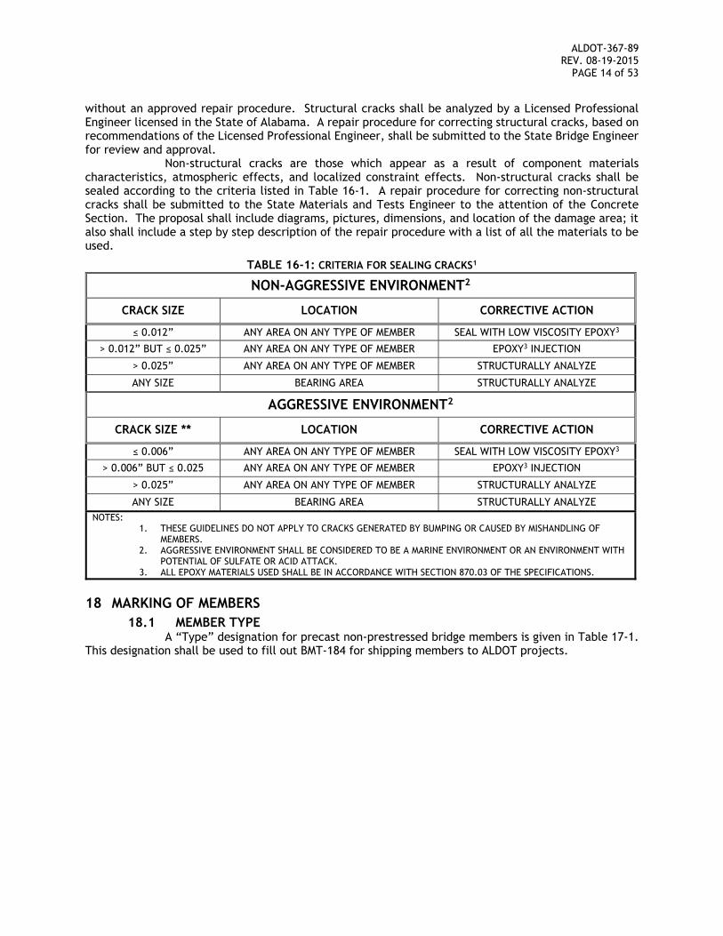
Non-structural cracks are those which appear as a result of component materials characteristics, atmospheric effects, and localized constraint effects. Non-structural cracks shall be sealed according to the criteria listed in Table 16-1. A repair procedure for correcting non-structural cracks shall be submitted to the State Materials and Tests Engineer to the attention of the Concrete Section. The proposal shall include diagrams, pictures, dimensions, and location of the damage area; it also shall include a step by step description of the repair procedure with a list of all the materials to be used.
TABLE 16-1: CRITERIA FOR SEALING CRACKS1
NON-AGGRESSIVE ENVIRONMENT2
CRACK SIZE LOCATION CORRECTIVE ACTION
≤ 0.012” ANY AREA ON ANY TYPE OF MEMBER SEAL WITH LOW VISCOSITY EPOXY3
> 0.012” BUT ≤ 0.025” ANY AREA ON ANY TYPE OF MEMBER EPOXY3 INJECTION
> 0.025” ANY AREA ON ANY TYPE OF MEMBER STRUCTURALLY ANALYZE
ANY SIZE BEARING AREA STRUCTURALLY ANALYZE
AGGRESSIVE ENVIRONMENT2
CRACK SIZE ** LOCATION CORRECTIVE ACTION
≤ 0.006” ANY AREA ON ANY TYPE OF MEMBER SEAL WITH LOW VISCOSITY EPOXY3
> 0.006” BUT ≤ 0.025 ANY AREA ON ANY TYPE OF MEMBER EPOXY3 INJECTION
> 0.025” ANY AREA ON ANY TYPE OF MEMBER STRUCTURALLY ANALYZE
ANY SIZE BEARING AREA STRUCTURALLY ANALYZE NOTES:
1. THESE GUIDELINES DO NOT APPLY TO CRACKS GENERATED BY BUMPING OR CAUSED BY MISHANDLING OF MEMBERS.
2. AGGRESSIVE ENVIRONMENT SHALL BE CONSIDERED TO BE A MARINE ENVIRONMENT OR AN ENVIRONMENT WITH POTENTIAL OF SULFATE OR ACID ATTACK.
3. ALL EPOXY MATERIALS USED SHALL BE IN ACCORDANCE WITH SECTION 870.03 OF THE SPECIFICATIONS.
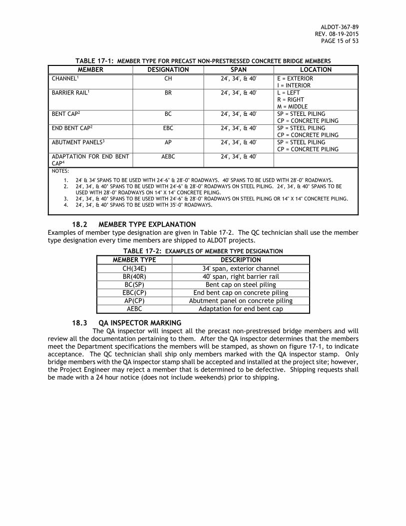
18 MARKING OF MEMBERS 18.1 MEMBER TYPE
A “Type” designation for precast non-prestressed bridge members is given in Table 17-1. This designation shall be used to fill out BMT-184 for shipping members to ALDOT projects.
ALDOT-367-89 REV. 08-19-2015
PAGE 15 of 53
TABLE 17-1: MEMBER TYPE FOR PRECAST NON-PRESTRESSED CONCRETE BRIDGE MEMBERS
MEMBER DESIGNATION SPAN LOCATION CHANNEL1 CH 24', 34', & 40' E = EXTERIOR
I = INTERIOR BARRIER RAIL1 BR 24', 34', & 40' L = LEFT
R = RIGHT M = MIDDLE
BENT CAP2 BC 24', 34', & 40' SP = STEEL PILING CP = CONCRETE PILING
END BENT CAP2 EBC 24', 34', & 40' SP = STEEL PILING CP = CONCRETE PILING
ABUTMENT PANELS3 AP 24', 34', & 40' SP = STEEL PILING CP = CONCRETE PILING
ADAPTATION FOR END BENT CAP4
AEBC 24', 34', & 40'
NOTES:
1. 24' & 34' SPANS TO BE USED WITH 24'-6" & 28'-0" ROADWAYS. 40' SPANS TO BE USED WITH 28'-0" ROADWAYS. 2. 24', 34', & 40’ SPANS TO BE USED WITH 24'-6" & 28'-0" ROADWAYS ON STEEL PILING. 24', 34', & 40’ SPANS TO BE
USED WITH 28'-0" ROADWAYS ON 14" X 14" CONCRETE PILING. 3. 24', 34', & 40’ SPANS TO BE USED WITH 24'-6" & 28'-0" ROADWAYS ON STEEL PILING OR 14" X 14" CONCRETE PILING. 4. 24', 34', & 40’ SPANS TO BE USED WITH 35'-0" ROADWAYS.
18.2 MEMBER TYPE EXPLANATION Examples of member type designation are given in Table 17-2. The QC technician shall use the member type designation every time members are shipped to ALDOT projects.
TABLE 17-2: EXAMPLES OF MEMBER TYPE DESIGNATION MEMBER TYPE DESCRIPTION
CH(34E) 34' span, exterior channel BR(40R) 40' span, right barrier rail BC(SP) Bent cap on steel piling
EBC(CP) End bent cap on concrete piling AP(CP) Abutment panel on concrete piling AEBC Adaptation for end bent cap
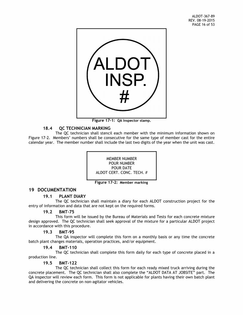
18.3 QA INSPECTOR MARKING The QA inspector will inspect all the precast non-prestressed bridge members and will
review all the documentation pertaining to them. After the QA inspector determines that the members meet the Department specifications the members will be stamped, as shown on figure 17-1, to indicate acceptance. The QC technician shall ship only members marked with the QA inspector stamp. Only bridge members with the QA inspector stamp shall be accepted and installed at the project site; however, the Project Engineer may reject a member that is determined to be defective. Shipping requests shall be made with a 24 hour notice (does not include weekends) prior to shipping.
ALDOT-367-89 REV. 08-19-2015
PAGE 16 of 53
Figure 17-1: QA Inspector stamp.
18.4 QC TECHNICIAN MARKING The QC technician shall stencil each member with the minimum information shown on
Figure 17-2. Members’ numbers shall be consecutive for the same type of member cast for the entire calendar year. The member number shall include the last two digits of the year when the unit was cast.
MEMBER NUMBER POUR NUMBER
POUR DATE ALDOT CERT. CONC. TECH. #
Figure 17-2: Member marking
19 DOCUMENTATION 19.1 PLANT DIARY
The QC technician shall maintain a diary for each ALDOT construction project for the entry of information and data that are not kept on the required forms.
19.2 BMT-75 This form will be issued by the Bureau of Materials and Tests for each concrete mixture
design approved. The QC technician shall seek approval of the mixture for a particular ALDOT project in accordance with this procedure.
19.3 BMT-95 The QA inspector will complete this form on a monthly basis or any time the concrete
batch plant changes materials, operation practices, and/or equipment.
19.4 BMT-110 The QC technician shall complete this form daily for each type of concrete placed in a
production line.
19.5 BMT-122 The QC technician shall collect this form for each ready mixed truck arriving during the
concrete placement. The QC technician shall also complete the “ALDOT DATA AT JOBSITE” part. The QA inspector will review each form. This form is not applicable for plants having their own batch plant and delivering the concrete on non-agitator vehicles.
ALDOT-367-89 REV. 08-19-2015
PAGE 17 of 53
19.6 BMT-183 The QC technician shall complete this form as a record of inspection for each line of
production of precast non-prestressed concrete bridge members.
19.7 BMT-184 The QC technician shall complete and maintain this form for each ALDOT project. This
form shall match the precast non-prestressed concrete bridge members listed for shipping on BMT-185.
19.8 BMT-185 The QC technician shall complete this form at the time of shipping precast non-
prestressed concrete bridge members to an ALDOT project. A copy of this form shall accompany the shipping members. The Project Engineer will use this form for payment purposes and file it in the project file.
19.9 BMT-209 The QA inspector will complete this form daily for each SCC placed in a production line.
19.10 BMT FORMS All of the required BMT forms can be found on ALDOT’s Testing Manual, located at http://www.dot.state.al.us/mtweb/Testing/testing_manual/BMT_Index.htm. The producer may electronically reproduce these forms.
20. TOLERANCES Precast non-prestressed concrete bridge members that are not cast within the following tolerances
will not be approved by the ALDOT QA inspector for shipment.
THE REST OF THIS PAGE LEFT INTENTIONALLY BLANK
ALDOT-367-89 REV. 08-19-2015
PAGE 18 of 53
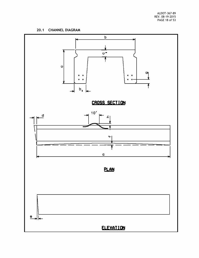
20.1 CHANNEL DIAGRAM
ALDOT-367-89 REV. 08-19-2015
PAGE 19 of 53
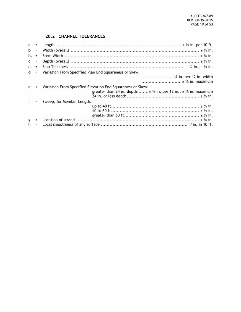
20.2 CHANNEL TOLERANCES
a = Length ....................................................................................... ± ⅛ in. per 10 ft.
b = Width (overall) ......................................................................................... ± ¼ in.
b1 = Stem Width ............................................................................................. ± ¼ in.
c = Depth (overall) . ........................................................................................ ± ¼ in.
c1 = Slab Thickness ................................................................................ + ¼ in., - ⅛ in.
d = Variation From Specified Plan End Squareness or Skew: .................... ± ⅛ in. per 12 in. width ........................... ± ½ in. maximum
e = Variation From Specified Elevation End Squareness or Skew: greater than 24 in. depth ........ ± ⅛ in. per 12 in., ± ½ in. maximum 24 in. or less depth .................................................. ± ¼ in.
f = Sweep, for Member Length: up to 40 ft ............................................................. ± ¼ in. 40 to 60 ft ............................................................. ± ⅜ in. greater than 60 ft .................................................... ± ½ in. g = Location of strand ..................................................................................... ± ¼ in. h = Local smoothness of any surface ............................................................ ¼in. in 10 ft.
ALDOT-367-89 REV. 08-19-2015
PAGE 20 of 53
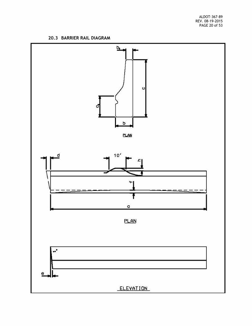
20.3 BARRIER RAIL DIAGRAM
ALDOT-367-89 REV. 08-19-2015
PAGE 21 of 53
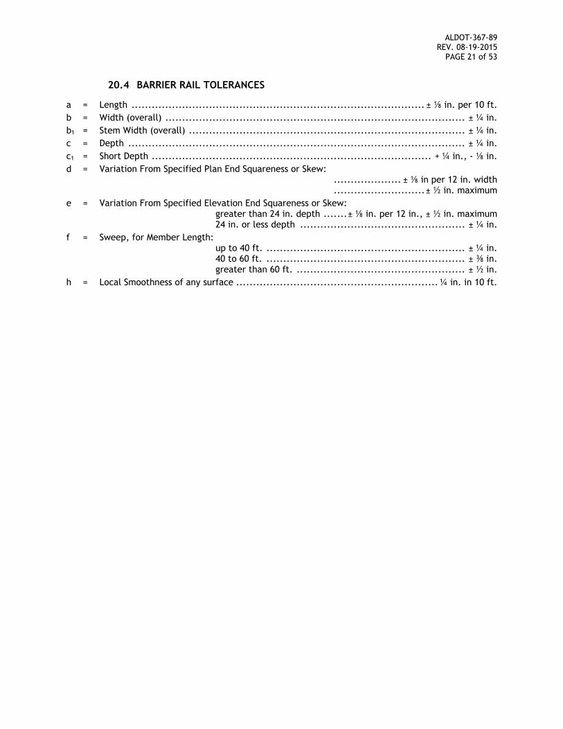
20.4 BARRIER RAIL TOLERANCES
a = Length ....................................................................................... ± ⅛ in. per 10 ft.
b = Width (overall) ......................................................................................... ± ¼ in.
b1 = Stem Width (overall) .................................................................................. ± ¼ in.
c = Depth .................................................................................................... ± ¼ in.
c1 = Short Depth ................................................................................... + ¼ in., - ⅛ in.
d = Variation From Specified Plan End Squareness or Skew: .................... ± ⅛ in per 12 in. width ........................... ± ½ in. maximum
e = Variation From Specified Elevation End Squareness or Skew: greater than 24 in. depth ....... ± ⅛ in. per 12 in., ± ½ in. maximum 24 in. or less depth ................................................. ± ¼ in.
f = Sweep, for Member Length: up to 40 ft. ........................................................... ± ¼ in. 40 to 60 ft. ........................................................... ± ⅜ in. greater than 60 ft. .................................................. ± ½ in.
h = Local Smoothness of any surface ............................................................ ¼ in. in 10 ft.
ALDOT-367-89 REV. 08-19-2015
PAGE 22 of 53
SECTION 2 PRECAST PRESTRESSED CONCRETE BRIDGE MEMBERS
BY PRE-TENSIONING
1 REFERENCE DOCUMENTS 1.1 ALDOT STANDARD SPECIFICATIONS FOR HIGHWAY CONSTRUCTION
Requirements for the materials and processes required for the production of precast prestressed concrete are given in the following Sections of the Specifications: (Web site link: ALDOT SPECIFICATIONS)
501 Structural Portland Cement Concrete 502 Steel Reinforcement 510 Bridges 513 Prestressed Concrete Bridge Members 801 Coarse Aggregate 802 Fine Aggregates 806 Mineral Admixtures 807 Water 808 Air Entraining Additives 809 Chemical Admixtures for Concrete 815 Cement 830 Concrete Curing Materials 834 Piling Materials 835 Steel reinforcement
1.2 ALDOT PROCEDURES Requirements for the materials and processes required for production of precast
prestressed concrete are given in the following ALDOT Procedures contained in the Testing Manual: (Web site link: ALDOT PROCEDURES)
170 Method of Controlling Concrete Operations for Structural Portland Cement Concrete
175 Method for Stockpiling Coarse Aggregate for All Purposes 352 Certification Program for Portland Cement Concrete Producers 355 General Information Concerning Materials, Sources, and Devices with Special
Acceptance Requirements 358 Jack Calibration Procedure 405 Certification and Qualification Program for Concrete Technicians and Concrete
Laboratories 407 Calibration Verification of Truck Mounted Water Meters 452 Sieve Stability Test for Self-Consolidating Concrete
1.3 BMT FORMS Documentation of the materials and processes required for production of precast
prestressed concrete shall be entered on the following BMT forms: 75 Concrete Mix Design 95 Concrete Plant Checklist 108 Product Inspection Report 109 Prestress Tensioning Worksheet 110 Concrete Placement Daily Report 122 Concrete Batch Ticket 139 Shipping Notice - Precast Prestress Concrete Bridge Members 209 Self-Consolidating Concrete Placement Daily Report
ALDOT-367-89 REV. 08-19-2015
PAGE 23 of 53
1.4 AASHTO STANDARDS Requirements for the materials and processes required for production of precast
prestressed concrete bridge members are given in the following AASHTO Standards: T 22 Compressive Strength of Cylindrical Concrete Specimens T 23 Making and Curing Concrete Test Specimens in the field T 24 Obtaining and Testing Drilled Cores and Sawed Beams of Concrete T 119 Slump of Hydraulic Cement Concrete T 121 Density (Unit Weight), Yield, and Air Content (Gravimetric) of Concrete T 152 Air Content of freshly Mixed Concrete by the Pressure Method T 160 Length Change of Hardened Hydraulic Cement Mortar and Concrete T 197 Time of Setting of Concrete Mixtures by Penetration Resistance T-309 Temperature of Freshly Mixed Portland Cement Concrete M 31 Deformed and Plain Billet Steel Bars for Concrete Reinforcement M 32 Cold Drawn Steel Wire for Concrete Reinforcement M 157 Ready-Mixed Concrete M 203 Uncoated Seven-Wire Stress-Relieved Strand for Prestressed Concrete M 275 Uncoated High-strength Steel Bar for Prestressing Concrete
1.5 ASTM STANDARDS Requirements for the materials and processes required for production of precast
prestressed concrete are given in the following ASTM Standards: C 1611 Standard Test Method for Slump Flow of Self-Consolidating Concrete C 1621 Standard Test Method for Passing Ability of Self-Consolidating Concrete by J-Ring
1.6 ACI STANDARD Requirements for the materials and processes required for production of precast
prestressed concrete are given in the following ACI Standards: 211.1 Practice for Selecting Proportions for Normal, Heavyweight, and Mass Concrete
1.7 PCI STANDARDS Requirements for the materials and processes required for production of precast
prestressed concrete bridge members are given in the following PCI Standards: TM-101 Quality Control Technician/Inspector Level I & II TM-103 Quality Control Personnel Certification Level III MNL-116 Quality Control for Plants and Production of Structural Precast Concrete
Products MNL-135 Tolerance Manual for Precast and Prestressed Concrete Construction
2 INITIAL PLANT QUALIFICATION REQUIREMENTS 2.1 QUALIFICATION SUBMITTAL
Producers of precast prestressed concrete must be qualified by ALDOT and placed on List I-10, PRODUCERS OF PRECAST NON-PRESTRESSED AND PRESTRESS CONCRETE BRIDGE MEMBERS, in order to supply precast prestressed concrete members to ALDOT projects. Any producer placed on List I-10 will be removed if the producer fails to adhere to the requirements given in this Procedure. Any producer wishing to supply precast prestressed concrete bridge members to ALDOT projects shall submit the following to the Concrete Engineer:
2.1.1 PLANT CERTIFICATION The producer of precast prestressed concrete products shall be certified by the
Precast/Prestressed Concrete Institute (PCI) Plant Certification Program. PCI certification shall be at least Category B4 (Prestressed Deflected Strand Bridge Members).
2.1.2 QUALITY CONTROL PLAN The producer of precast prestressed concrete products shall submit a Quality Control Plan
to the Materials and Tests Engineer. The procedures for controlling and monitoring the quality of the prestressed concrete during production shall be given in this plan. The Quality Control Plan shall identify
ALDOT-367-89 REV. 08-19-2015
PAGE 24 of 53
the plant’s certified Quality Control Technician(s), as defined in Section 4 of this document, and provide proof of said certifications.
2.1.3 FEES PER ALDOT-355 All applicable fees & forms shall be submitted, per ALDOT-355.
2.2 PLANT INSPECTION Upon receipt & acceptance of all items listed in Section 2.1, an inspection of the plant
facilities will be scheduled. Areas & items to be inspected will be documented on BMT-210, “Plant Inspection Form for Precast/Prestress Concrete Bridge Member & Pole Producers”. Any deficiencies must be corrected prior to adding the plant to List I-10.
3 PLANT REQUALIFICATION REQUIREMENTS 3.1 ANNUAL REQUALIFICATION
Producers of precast prestressed concrete shall be requalified by ALDOT on an annual basis in order to remain on List I-10. As part of requalification, the following shall be submitted each December by qualified producers:
Proof of continual maintenance of PCI certification. Updated copy of the plant’s Quality Control Plan, including technician
certifications. Fees per ALDOT-355.
3.2 PLANT INSPECTION Plants actively producing for ALDOT projects will be inspected continuously throughout
the year during production, as described in the remainder of this procedure. These plants shall only be charged one fee in December each year.
Plants which have not produced for ALDOT within the preceding year shall have an inspection scheduled with ALDOT during December. All other requalification submittals shall be provided to the inspector at that time.
4 PLANT QUALITY CONTROL TECHNICIAN The producer of the precast prestressed concrete products shall have at least one Quality Control
(QC) technician present on each line of production. This QC technician shall be responsible for all aspects of production from the initial preparations for casting to the shipment of the members. The QC technician shall be responsible for insuring that the materials and workmanship meet the requirements given in the Specifications, on the Plans, and described in this Procedure.
The QC technician shall be certified as an ALDOT Concrete Technician. This technician shall also be certified as a PCI Level I/II technician.
The QC technician shall be responsible for the following in the sequence of production: Inspection of production facilities and materials prior to concrete placement Inspection of concrete placement and curing of members Inspection of precast products after curing and during handling and storage Inspection of handling and shipping
The QC technician shall also be responsible for the following: Enforce compliance with the Quality Control Program Sample materials for testing and prepare sampling documentation Submit materials to be tested to the Bureau of Materials and Tests Be present during production and shipment of precast components Perform quality control tests and measurements Ensure that test equipment is calibrated and maintained Inspect each precast component Ensure that all products are properly cured Maintain a daily production log Ensure that all products are marked in accordance with this procedure Ensure that all products are properly stored
ALDOT-367-89 REV. 08-19-2015
PAGE 25 of 53
Fill out, submit, and maintain test report and production documentation Prepare and maintain documentation of sampling, testing and material sources Ensure that all materials used during production are from ALDOT approved sources
5 ALDOT'S QUALITY ASSURANCE INSPECTOR Quality Assurance (QA) inspection will be performed by a technician assigned by the ALDOT. The
QA inspector will review the work of the producer's QC technician to verify that all of the operations required for the production of precast prestressed concrete bridge members are being done in accordance with the requirements given in the Specifications, given on the Plans and described in this Procedure.
The QA inspector will be certified as an ALDOT Concrete Technician and will also be certified as a PCI Level I/II technician.
The QA inspector will review the proposed production operations with the producer's QC inspector prior to production so that there will be no misunderstandings concerning the requirements for production.
The QA inspector shall monitor all production related activities including all sampling, testing and prestressing.
The QA inspector shall be responsible for the following: Perform plant inspections Review the work of the producer's QC technician Perform pre-placement inspections Perform concrete placement inspections Perform post-placement inspections Perform shipping inspections Place identification on producer's products to signify approval for shipping of precast
prestressed concrete bridge members
6 ALDOT'S SUPERVISORY PERSONNEL The ALDOT's Quality Assurance (QA) technician will be assisted by supervisory personnel from the
Materials and Tests Bureau. Supervisory personnel will monitor work of the QA inspector and will be responsible for the following:
Process requests for approval of all new sources of materials Process requests for approval of all new producers of precast prestressed components Maintain the approved list of producers Review the producer’s Quality Control plan Review producer's proposals for the repair of damaged members
7 INSPECTION FACILITIES The producer shall provide all facilities for inspection of materials and workmanship at the
fabrication plant. The producer shall provide the QA inspectors access to a work station located inside the plant perimeter. This work station shall meet the following minimum requirements and include the following minimum equipment without extra compensation from the Department:
Not less than 150 square feet of floor space Minimum width of 10 feet and minimum ceiling height of 7 feet It shall have not less than two windows One entrance door with lock It shall have a watertight roof Insulated and weather tight Include operational heating and air-conditioning Functional electrical service A minimum of two desks with chairs A minimum of 2 five-drawer file cabinets with lock A minimum of two supplies cabinets
ALDOT-367-89 REV. 08-19-2015
PAGE 26 of 53
Functional telephone service with outside line Functional fax service and copy machine
8 SHOP DRAWINGS The ALDOT Bridge Bureau will approve and distribute shop drawings showing the type of
prestressing, bed layouts, calculations for elongation, friction losses, sequences for stressing and detensioning, and any other data required for the production of prestressed concrete bridge members. Production of the prestressed concrete bridge members shall be in accordance with the details shown on approved shop drawings.
9 MATERIALS 9.1 TYPE AND QUALITY OF MATERIALS
The type and quality of materials required for precast prestressed production shall be in accordance with the requirements given in the Specifications, shown on the Plans and described in this Procedure.
9.2 SUBMITTAL OF CONCRETE MIXTURE DESIGN The producer shall submit a proposal of the proportions of materials for each type of
concrete used for production of precast prestressed concrete bridge members. The proposal of the mixture design shall be in accordance with the requirements given in ALDOT-170, the requirements given in Section 513, and the requirements given in this procedure.
Concrete mixes may be designed either by a commercial laboratory or by the production plant laboratory. Commercial or plant laboratories shall meet the requirements given in ALDOT-405.
The producer shall obtain the Material and Tests Engineer's approval of the mixture design prior to using the mixture for production of precast prestressed concrete bridge members. The mixture design shall be resubmitted for approval if there are any changes to the type, source or proportions of materials. The re-approval of the mixture design shall be as described in ALDOT-170.
Item 4 of ALDOT-170 shall be amended by the requirement that three cylinders shall be made for testing the compressive strength of the concrete at an age of one day. The 1-day specimens shall be cured the same way that the components are cured for the first 24 hours. The results of the compressive strength testing of the 1-day cylinders shall be plotted on the water-cementitious ratio vs. strength curve.
The use of 4 X 8 cylinders may be allowed provided the producer submits, as part of the mixture design submittal, a correlation comparing 6 X 12 cylinders versus 4 X 8 cylinders, and such correlation is equal to 1.0 or higher.
9.3 ADDITIONAL REQUIRED TESTING FOR SCC MIXTURES The design of the SCC shall be in compliance with the requirements given in Item
513.02(c)3. All SCC test specimen molds, air content buckets, and unit weight buckets shall be filled in one continuously poured lift using a suitable container without vibration, rodding, or tapping. The SCC shall be dropped from a height of 6 inches ± 2.0 inches above the top of the mold or bucket into the center of the container, unless otherwise specified. The SCC shall be struck off level with the top of the mold or bucket.
9.3.1 SLUMP FLOW TESTING The filling ability of SCC shall be determined by slump flow testing in accordance with the requirements of ASTM C 1611. The slump flow test shall be performed using the mold in the inverted position, defined as Filling Procedure B in ASTM C 1621.
9.3.2 PASSING ABILITY TESTING The passing ability of SCC shall be determined by J-Ring testing in accordance with the requirements of ASTM C 1621. The passing ability test shall be performed using the mold in the inverted position, defined as Filling Procedure B in ASTM C 1621.
ALDOT-367-89 REV. 08-19-2015
PAGE 27 of 53
9.3.3 STABILITY TESTING The Visual Stability Index (VSI) shall be used to assess the stability of SCC for mixture approval. The VSI shall be assigned in accordance with the requirements of the Appendix of ASTM C 1611.
9.3.4 DRYING SHRINKAGE TESTING The drying shrinkage shall be determined in accordance with the requirements of AASHTO T 160, except as specified in this section. The SCC sample shall be obtained from a minimum size batch of 3 cubic yards from the concrete producer’s batch plant. The SCC shall be produced to meet the total air content, slump flow, stability, temperature, and strength requirements as defined in Item 513.02(c)3. The shrinkage prisms shall be made and initially cured in the field at the producer’s facility. The concrete constituent materials are not required to meet the temperature requirements of AASHTO T 160. Prisms shall be molded on a level and vibration free surface at a place as near as practicable to the location where they are to be stored. Within 15 minutes following strike off, the prisms shall be placed in the shade and in a vibration free environment. After setting and while in the molds, all prisms shall be immersed in a lime-saturated water bath maintained at a temperature from 60 to 80 °F. Transport the prisms in the molds at a concrete age of 18 to 23.5 hours to the facility where curing will be continued in a lime-saturated water tank in accordance with AASHTO T 160. Drying of the prism surfaces is not allowed at any time. Moisture loss during transportation shall be prevented by covering the prisms with wet burlap and plastic or by transporting the prisms in a lime-saturated water tank. Support the prisms sufficiently to prevent damage during transportation. Remove the prisms from their molds at an age of 23.5 0.5 hours after the addition of water to the cement during the fabrication of the prisms. Upon removal of the specimens from the molds, immediately place them in lime-saturated water maintained at 73 3 °F. Before being measured for length, all prisms must have been in a lime-saturated water maintained at 73 1°F for at least 30 minutes. At an age of 7 days 0.5 hours after the addition of water to the cement, remove the specimens from water storage one at a time, wipe with a damp cloth, and immediately take the initial comparator reading. All prisms shall be exposed to drying at a concrete age of 7 days 0.5 hours after the addition of water to the cement. The environment in the drying room shall meet the requirements of AASHTO T 160. The 28-day drying shrinkage is defined as the shrinkage obtained after 28 day of exposure to drying relative to the initial comparator reading.
9.3.5 ROBUSTNESS TESTING Well-proportioned SCC shall be robust to ensure that segregation of the mixture does not occur during or after placement. Robustness testing shall be performed on a minimum size batch of 3 cubic yards from the concrete producer’s batch plant. No water may be withheld from the minimum batch size of 3 cubic yards. The SCC shall be produced to meet the total air content, slump flow, stability, temperature, and strength requirements as defined in Item 513.02(c)3. A representative sample shall be taken and the unit weight shall be determined in accordance with the requirements given in AASHTO T 121. After completion of the unit weight test, a 2 cubic foot sample shall be taken for further testing. The concrete weight of the 2 cubic foot sample shall be calculated from the unit weight test result. The 2 cubic foot sample shall be added to a buttered rotating-drum mixer and additional water shall be added to the mixture. The additional water shall equal 2 % of the total fine aggregate saturated-surface dry weight in the 2 cubic foot sample. The concrete sample with the added water shall be mixed for 1 minute and then the tests for mixture robustness (Slump Flow and Visual Stability Index) shall be performed. The Slump Flow and VSI tests shall be completed within 5 minutes after completion of mixing with additional water.
9.4 SIZE OF COARSE AGGREGATE The size of coarse aggregate shall not be larger than 1/5 of the narrowest space between
the sides of the forms. The size of the coarse aggregate shall also not be larger than 3/4 of the narrowest clear spacing between individual reinforcing bars or bundles of bars. Coarse aggregate for SCC shall meet the requirements of Item 513.02(c)3.
ALDOT-367-89 REV. 08-19-2015
PAGE 28 of 53
9.5 CHEMICAL ADMIXTURES Chemical admixtures may be used to increase the slump of the concrete if this is shown
on the approved mixture design. Chemical admixtures may be used to alter the slump flow and stability of self-consolidating concrete if these admixtures are shown on the approved mixture design.
9.6 MINERAL ADMIXTURES Mineral admixtures may be used as part of the cementitious material if this is shown on
the approved mixture design.
9.7 REINFORCING STEEL The certifications for the steel reinforcement shall be submitted to the Materials and
Tests Engineer for review. The certifications shall include the actual test results for each lot of reinforcing steel. Certifications that include typical test results for steel reinforcing in general are unacceptable.
Steel reinforcement will be evaluated for acceptance on certification meeting the requirements given in AASHTO M 31 and could be subject to the procedures given for Independent Assurance Sampling and Testing (IAS&T). (Web link: IAS&T)
9.8 PRESTRESSING STEEL All prestressing steel shall be packaged and marked as shown to be required in AASHTO M
203. Strand for prestressing concrete shall be sampled and tested in accordance with the requirements given in AASHTO M 203. Steel bars for prestressing concrete shall be sampled and tested in accordance with the requirements given in AASHTO M 275.
Three 6 foot long samples shall be obtained for each lot of prestressing strand representing not more than 50,000 pounds or approximately seven reels. These samples shall be marked and delivered to the Bureau of Materials and Tests for testing. Prestressing strand shall not be used prior to testing or after a failing test result.
9.9 MISCELLANEOUS ITEMS AND ACCESSORIES. Sampling and testing of miscellaneous items and accessories shall be done in accordance
with the requirements given in Division 800 for the type of material being furnished.
10 PRESTRESSING REQUIREMENTS 10.1 TENSIONING OF STRANDS
Prestressing strands are multiple wire steel cables. The control and evaluation of the application of the prestressing force shall be based on the measurement of applied tension force and on theoretical and actual strand elongation. A calibrated gage shall be used for the measurement of the tension force applied to the strand. The actual measured tension force of a strand shall be compared to the theoretical (or mathematically calculated) tension force of the strand.
The theoretical (or mathematically predicted) elongation of the strand shall be calculated before the tensioning begins. This theoretical elongation is based on the length of the strand, the force applied to the strand, and other properties of the strand. The actual elongation of the strand shall be compared to the theoretical elongation.
There are three tolerances that tensioning must be held within for the tensioning to be considered acceptable. The first tolerance is that the gage measurement of the tension force shall be within ± 5% of the theoretical computed force (required force). The second tolerance is that the measured elongation shall be within ± 5% of the theoretical computed elongation. The third tolerance is that the difference between the control measurements of force and elongation shall algebraically agree with each other within ± 5%. If any of the three tolerances are exceeded the tensioning operation shall be suspended until the source of error is determined and corrected.
As an example of applying tolerances, if the gauge force is 3% above its theoretical calculated value and elongation is 3% below its theoretical calculated values; the difference between these two control measurements is 6% which is outside the acceptable range. An illustration of this is given in Figure 9-1.
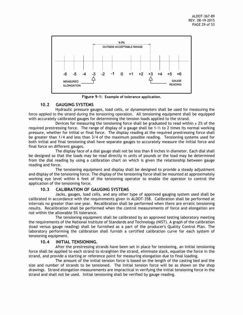
ALDOT-367-89 REV. 08-19-2015
PAGE 29 of 53
Figure 9-1: Example of tolerance application.
10.2 GAUGING SYSTEMS Hydraulic pressure gauges, load cells, or dynamometers shall be used for measuring the
force applied to the strand during the tensioning operation. All tensioning equipment shall be equipped with accurately calibrated gauges for determining the tension loads applied to the strand.
Devices for measuring the tensioning force shall be graduated to read within ± 2% of the required prestressing force. The range of display of a gauge shall be 1-½ to 2 times its normal working pressure, whether for initial or final force. The display reading at the required prestressing force shall be greater than 1/4 and less than 3/4 of the maximum possible reading. Tensioning systems used for both initial and final tensioning shall have separate gauges to accurately measure the initial force and final force on different gauges.
The display face of a dial gauge shall not be less than 8 inches in diameter. Each dial shall be designed so that the loads may be read directly in units of pounds or the load may be determined from the dial reading by using a calibration chart on which is given the relationship between gauge reading and force.
The tensioning equipment and display shall be designed to provide a steady adjustment and display of the tensioning force. The display of the tensioning force shall be mounted at approximately working eye level within 6 feet of the tensioning operator to enable the operator to control the application of the tensioning force.
10.3 CALIBRATION OF GAUGING SYSTEMS Jacks, gauges, load cells, and any other type of approved gauging system used shall be
calibrated in accordance with the requirements given in ALDOT-358. Calibration shall be performed at intervals no greater than one year. Recalibration shall be performed when there are erratic tensioning results. Recalibration shall be performed when the control measurements of force and elongation are not within the allowable 5% tolerance.
The tensioning equipment shall be calibrated by an approved testing laboratory meeting the requirements of the National Institute of Standards and Technology (NIST). A graph of the calibration (load versus gauge reading) shall be furnished as a part of the producer's Quality Control Plan. The laboratory performing the calibration shall furnish a certified calibration curve for each system of tensioning equipment.
10.4 INITIAL TENSIONING. After the prestressing strands have been set in place for tensioning, an initial tensioning
force shall be applied to each strand to straighten the strand, eliminate slack, equalize the force in the strand, and provide a starting or reference point for measuring elongation due to final loading.
The amount of the initial tension force is based on the length of the casting bed and the size and number of strands to be tensioned. The initial tension force will be as shown on the shop drawings. Strand elongation measurements are impractical in verifying the initial tensioning force in the strand and shall not be used. Initial tensioning shall be verified by gauge reading.
ALDOT-367-89 REV. 08-19-2015
PAGE 30 of 53
The initial tensioning force shall be uniformly distributed throughout the length of the strand. Places where the strand passes through stirrups, spirals, or headers shall be carefully inspected to make sure that the strand is not being bound or restricted from stretching.
10.5 STRAND POSITION AND STRESSING SEQUENCE Strands shall be positioned in accordance with the dimensions shown in the shop drawings.
Strands shall be supported as required to maintain the vertical and horizontal position within the specified tolerances.
A sequence shall be established for installing and tensioning strands. In most cases, the placement of the strands shall progress from the bottom row of the strand group to the top row and the tensioning shall progress from the top row of the strand group to the bottom row.
10.6 ELONGATION MEASUREMENT AND CORRECTIONS The purpose of measuring elongation in the strands is to verify that the required
prestressing tension force is present in the strands. A strand will stretch in a very predictable manner when the tension force is applied. The prediction of the elongation is done by calculation.
After an initial tension force has been applied to the strands, reference points shall be marked to establish the beginning points for the measurement of the elongation of the strands. For single strand tensioning, elongation can be measured by marking or taping the strand behind the anchorages (chucks). For multiple strands tensioning, elongation can be measured by marking the stressing headers on both sides of the stressing bed.
The elongations measured from the referenced points shall be compared to the elongations predicted by calculation. The measured elongations shall be within ± 5 % of the values predicted by calculation.
If the tension forces and elongations are within the allowable tolerances for the first two strands monitored in each stress group, tensioning may continue with reduced monitoring of the elongation. If allowed by the QA inspector, reduced monitoring of elongation will be performed on the first two strands in each stress group and at least 25% of the remaining strands.
Elongations measurements shall take into account all operational losses and compensations in the tensioning system. Corrections to the basic computed elongation vary between casting beds and strands setups and shall be evaluated and compensated for in computing the total elongation. Elongation corrections may be needed due to the following operating variables:
10.6.1 STRAND SEATING 10.6.1.1 DEAD END SEATING
A dead end seating loss occurs between the time that initial tension is applied to the strand and the application of the final tension. It will show up as added elongation in the measured elongation.
10.6.1.2 LIVE END SEATING A live end seating loss occurs as the strand is released from the
jack after the final force is applied. In multiple strands tensioning live end seating is relatively small and can be ignored.
10.6.1.3 SPLICE CHUCK SEATING This loss is similar to dead end seating. The strand shall be marked
on both sides of the chuck to determine the amount of the seating loss. It will show up as added elongation in the measured elongation.
10.6.2 FORM SHORTENING Self-stressing forms will take on the force of the tensioned strands as a
compressive load therefore shortening the bed.
10.6.3 THERMAL EFFECTS Changes in strand temperature may result in stress changes. Corrections to
the elongation shall correspond to the changes in stress. This correction does not apply to self-stressing beds.
ALDOT-367-89 REV. 08-19-2015
PAGE 31 of 53
10.6.4 ABUTMENT ROTATION OR MOVEMENT OF ANCHORAGES For each pretensioning operation, the yield, deflection, or movement of the
anchoring abutment shall be determined. The significance of the difference between the assumed and measured abutment movement is dependent upon the distance between the anchoring abutments. The abutment movement shall be measured from a reference point to the center of gravity of the strand or group of strands.
10.6.5 ELONGATION OF ABUTMENT ANCHORING RODS If anchor bolts under tensile stresses are used in the abutment anchoring
system, the elongation of these bolts shall be considered in the elongation corrections. The significance of this value is also dependent on the length of the stressing bed. Anchoring rods are used typically with multiple strand tensioning.
10.6.6 STRAND ‘UNWINDING’ When single strand jacking is used, the jacking ram will have a tendency to
rotate due to the “untwisting” action of the strands. This rotation can result in considerable losses if unwinding in excess of one turn occurs.
10.7 FORCE CORRECTIONS 10.7.1 LIVE END SEATING
To add additional elongation to the basic elongation to offset seating losses requires additional force to be added to the desired theoretical force.
10.7.2 FORM SHORTENING Applied load must be adjusted to offset the increase of elongation resulting
from bed shortening adjustments.
10.7.3 THERMAL EFFECTS Changes in the temperature of the strands will result in a change in the force
in the strands. Lowering the strand temperature increases force while a temperature rise results in force loss. A temperature variation of 10 ºF in the strand will result in a variation of 1% in stress.
Corrections for temperature variations of 25 °F or more shall only be made with the approval of the QA inspector. The QA inspector will ask for the assistance of ALDOT supervisory personnel in considering what should be done to address the effects of temperature variations in excess of 25 °F.
It is usually easy to predict the temperature of the concrete at the time of the initial set with sufficient accuracy. The temperature of the concrete during casting of prestressed concrete bridge members shall be maintained for approximately 4 hours or until the initial set has been attained.
10.7.4 ABUTMENT ROTATION OR MOVEMENT OF ANCHORAGES If the deflection resulting from abutment rotation or movement of anchorages
produces a loss in strand tension, which combined with other factors results in a variation outside of the 5% tolerance, then an adjustment is required.
10.8 FINAL TENSIONING 10.8.1 STRAIGHT STRANDS
The required prestressing tension load shall be applied only after the application of the initial tension force and the placement of reference marks for measuring elongation. If the tension forces and elongations are within the allowable tolerances for the first two strands monitored in each stress group, the QA inspector may allow some of the remaining strands to be tensioned without monitoring elongation. At least 25 % of the remaining strands in the group of identical strands shall be fully monitored by measuring the tension force in the strand and the elongation.
10.8.2 DRAPED STRANDS 10.8.2.1 LOAD CELL AT DEAD END OF STRAND
The prestressing tension force may be less than the required amount of force at the dead end of a draped strand due to the loss of force caused by the deflection of
ALDOT-367-89 REV. 08-19-2015
PAGE 32 of 53
the strand. A load cell shall be installed at the dead end of at least one draped strand in each stress group. This load cell shall be used to verify that the prestressing tension force is present at the dead end of the strand. Tensioning operations shall be stopped to correct the problem of not having the required amount of force in the strand at the dead end.
10.8.2.2 LENGTH OF DRAPED STRAND The length of the strand used in calculating elongations shall be
the actual length of the strand along the straight and deflected path between the live end and the dead end. Draped strands shall be positioned within the allowable tolerances.
10.8.2.3 DEFLECTING STRANDS AFTER PARTIAL TENSIONING. Strands may be tensioned in a straight or partially draped position
to a pre-determined intermediate tensioning value between initial and final tensioning. The final tension force is put into the strands by the deflection of the strand into the required draped position. The deflection of the strands into the final draped position shall be done by the simultaneous movement of all points of deflection as shown on the approved shop drawings, or by any designated sequence approved by the State Bridge Engineer that will result in the strands having the required final tension force.
10.8.2.4 TENSIONING STRANDS IN THE REQUIRED DRAPED POSITION Strands may be tensioned to the required final tension force in the
fully draped position. The devices used to hold the strands in place shall not bind the strands or cause friction losses that will result in an unequal distribution of the tension force in different segments of the strand.
Tensioning the strands from both ends may be required to evenly distribute the required tension force along the length of the strands. The tolerances for the correlation of the tension force and elongations shall apply to tensioning the strands at both ends.
10.8.2.5 CONCRETE COVER OVER STRAND DEFLECTION DEVICES There shall be a minimum of 1 1/8 inch of concrete cover over all
metal parts of the hold-down devices remaining within the member. The details of the devices proposed for use in deflecting the strands shall be submitted as a part of the producers Quality Control Plan.
10.9 PRESTRESS CALCULATIONS 10.9.1 ELONGATION FORMULA
The computation of elongation is based on a force which is a percentage of the ultimate capacity of the strand. The modulus of elasticity and area of the strand shall be supplied by the strand manufacturer. Elongation calculations are shown on the shop drawings.
The QA inspector will make adjustments to the elongation calculations based on actual bed set up and recorded losses. The example calculations depicted on Items 9.9.3 thru 9.9.6 will be used as guidelines to make adjustments. Any adjustment beyond the ones presented in this procedure shall be review and approved by the Bridge Engineer prior to implementation. To determine the elongation (∆) use the following equation:
AEPL
Where:
∆ = Elongation (in) P = Force required after initial tensioning (lbf) L = Length of strand from chuck to chuck A = Cross-section area of a strand (in2) E = Modulus of Elasticity of strand (psi)
10.9.2 STRAND AVERAGE VALUES During actual prestress operations several rolls of strand are used at the same
time. These rolls of strand may have different heat numbers; therefore, their strand area and elastic modulus may vary. An average strand area and modulus of elasticity may be used on the calculations provided that the area and modulus of elasticity of each strand is not more than 2.5% from the average and the product (AxE) is within 2.5% of the product of average values.
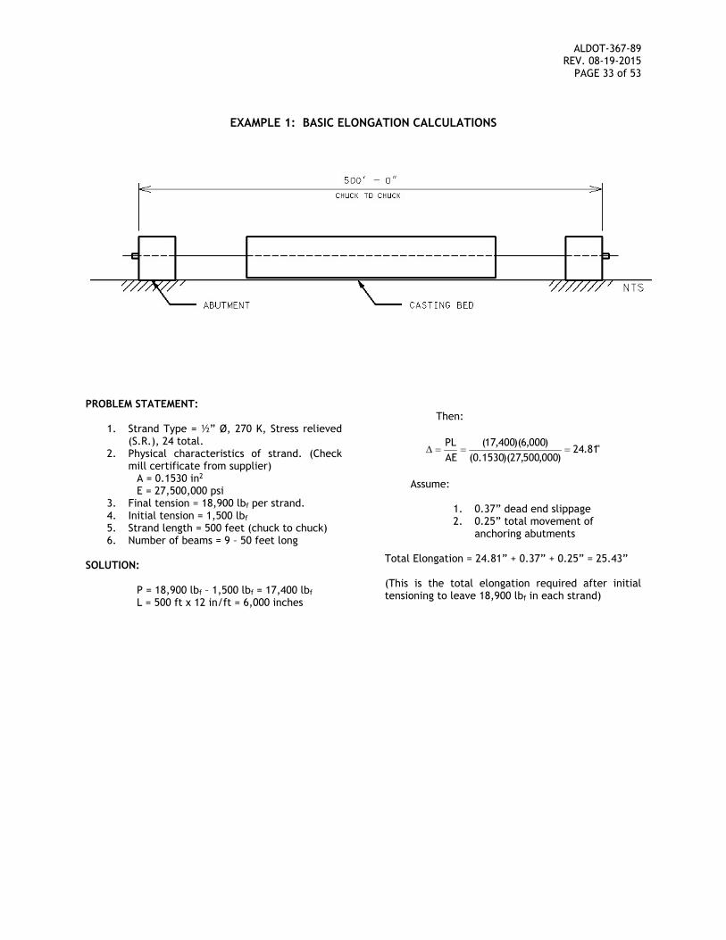
ALDOT-367-89 REV. 08-19-2015
PAGE 33 of 53
EXAMPLE 1: BASIC ELONGATION CALCULATIONS
PROBLEM STATEMENT:
1. Strand Type = ½” Ø, 270 K, Stress relieved (S.R.), 24 total.
2. Physical characteristics of strand. (Check mill certificate from supplier)
A = 0.1530 in2 E = 27,500,000 psi
3. Final tension = 18,900 lbf per strand. 4. Initial tension = 1,500 lbf 5. Strand length = 500 feet (chuck to chuck) 6. Number of beams = 9 – 50 feet long
SOLUTION:
P = 18,900 lbf – 1,500 lbf = 17,400 lbf L = 500 ft x 12 in/ft = 6,000 inches
Then:
"81.24)000,500,27)(1530.0(
)000,6)(400,17(AEPL
Assume:
1. 0.37” dead end slippage 2. 0.25” total movement of
anchoring abutments Total Elongation = 24.81” + 0.37” + 0.25” = 25.43” (This is the total elongation required after initial tensioning to leave 18,900 lbf in each strand)
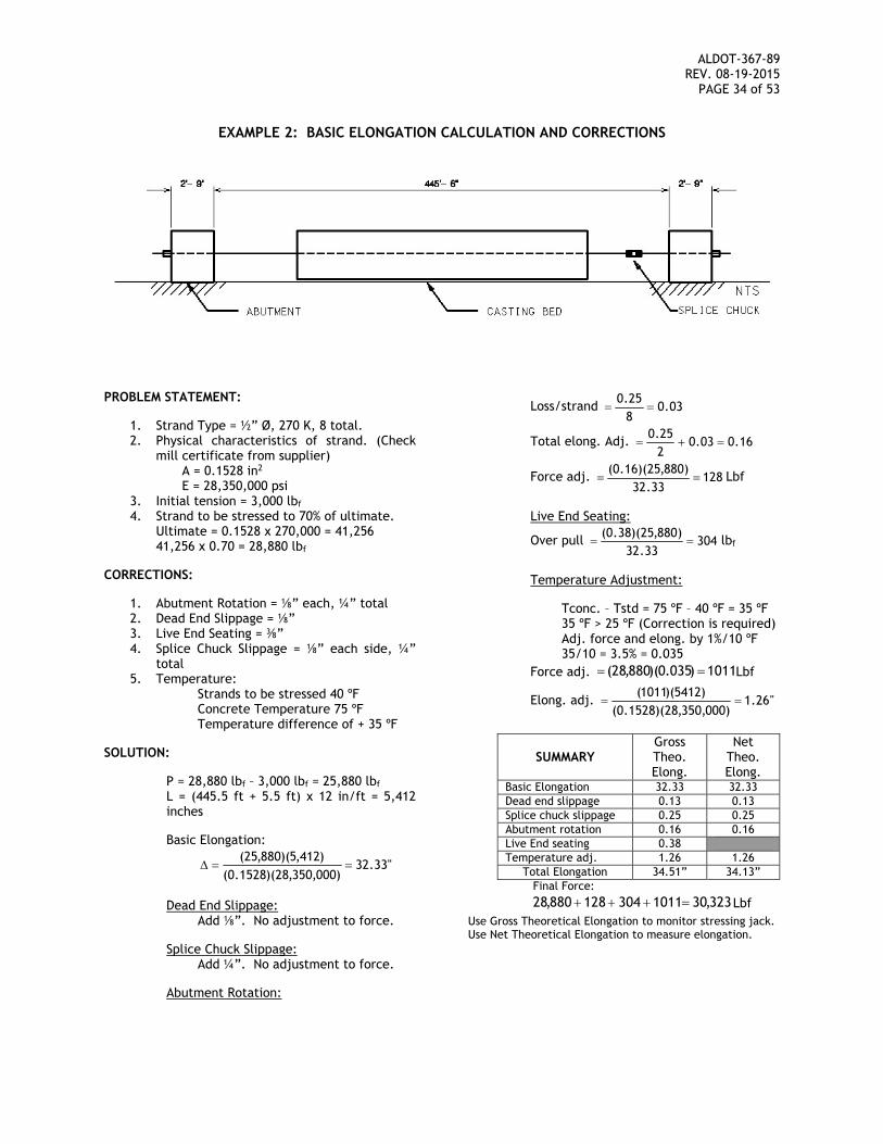
ALDOT-367-89 REV. 08-19-2015
PAGE 34 of 53
EXAMPLE 2: BASIC ELONGATION CALCULATION AND CORRECTIONS
PROBLEM STATEMENT:
1. Strand Type = ½” Ø, 270 K, 8 total. 2. Physical characteristics of strand. (Check
mill certificate from supplier) A = 0.1528 in2 E = 28,350,000 psi
3. Initial tension = 3,000 lbf 4. Strand to be stressed to 70% of ultimate.
Ultimate = 0.1528 x 270,000 = 41,256 41,256 x 0.70 = 28,880 lbf
CORRECTIONS:
1. Abutment Rotation = ⅛” each, ¼” total 2. Dead End Slippage = ⅛” 3. Live End Seating = ⅜” 4. Splice Chuck Slippage = ⅛” each side, ¼”
total 5. Temperature:
Strands to be stressed 40 ºF Concrete Temperature 75 ºF Temperature difference of + 35 ºF
SOLUTION:
P = 28,880 lbf – 3,000 lbf = 25,880 lbf L = (445.5 ft + 5.5 ft) x 12 in/ft = 5,412 inches
Basic Elongation:
"33.32)000,350,28)(1528.0(
)412,5)(880,25(
Dead End Slippage:
Add ⅛”. No adjustment to force.
Splice Chuck Slippage: Add ¼”. No adjustment to force.
Abutment Rotation:
Loss/strand 03.0825.0
Total elong. Adj. 16.003.0225.0
Force adj. 12833.32
)880,25)(16.0( Lbf
Live End Seating:
Over pull 30433.32
)880,25)(38.0( lbf
Temperature Adjustment:
Tconc. – Tstd = 75 ºF – 40 ºF = 35 ºF 35 ºF > 25 ºF (Correction is required) Adj. force and elong. by 1%/10 ºF 35/10 = 3.5% = 0.035
Force adj. 1011)035.0)(880,28( Lbf
Elong. adj. "26.1)000,350,28)(1528.0(
)5412)(1011(
SUMMARY Gross Theo. Elong.
Net Theo. Elong.
Basic Elongation 32.33 32.33 Dead end slippage 0.13 0.13 Splice chuck slippage 0.25 0.25 Abutment rotation 0.16 0.16 Live End seating 0.38 Temperature adj. 1.26 1.26
Total Elongation 34.51” 34.13” Final Force:
323,301011304128880,28 Lbf Use Gross Theoretical Elongation to monitor stressing jack. Use Net Theoretical Elongation to measure elongation.
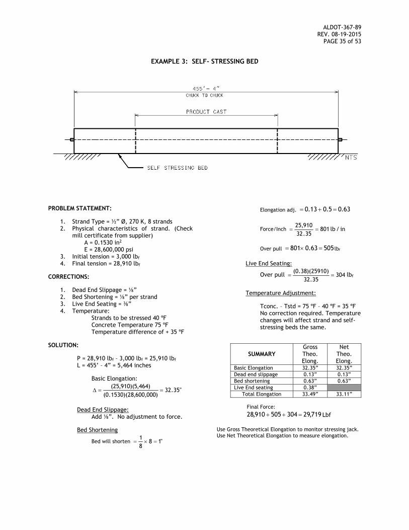
ALDOT-367-89 REV. 08-19-2015
PAGE 35 of 53
EXAMPLE 3: SELF- STRESSING BED
PROBLEM STATEMENT:
1. Strand Type = ½” Ø, 270 K, 8 strands 2. Physical characteristics of strand. (Check
mill certificate from supplier) A = 0.1530 in2 E = 28,600,000 psi
3. Initial tension = 3,000 lbf 4. Final tension = 28,910 lbf
CORRECTIONS:
1. Dead End Slippage = ⅛” 2. Bed Shortening = ⅛” per strand 3. Live End Seating = ⅜” 4. Temperature:
Strands to be stressed 40 ºF Concrete Temperature 75 ºF Temperature difference of + 35 ºF
SOLUTION:
P = 28,910 lbf – 3,000 lbf = 25,910 lbf L = 455’ – 4” = 5,464 inches
Basic Elongation:
"35.32)000,600,28)(1530.0(
)464,5)(910,25(
Dead End Slippage:
Add ⅛”. No adjustment to force.
Bed Shortening
Bed will shorten "1881
Elongation adj. 63.05.013.0
Force/Inch in/lb80135.32
910,25
Over pull 50563.0801 lbf
Live End Seating:
Over pull 30435.32
)25910)(38.0( lbf
Temperature Adjustment:
Tconc. – Tstd = 75 ºF – 40 ºF = 35 ºF No correction required. Temperature changes will affect strand and self-stressing beds the same.
SUMMARY
Gross Theo. Elong.
Net Theo. Elong.
Basic Elongation 32.35” 32.35” Dead end slippage 0.13” 0.13” Bed shortening 0.63” 0.63” Live End seating 0.38”
Total Elongation 33.49” 33.11” Final Force:
719,29304505910,28 Lbf Use Gross Theoretical Elongation to monitor stressing jack. Use Net Theoretical Elongation to measure elongation.
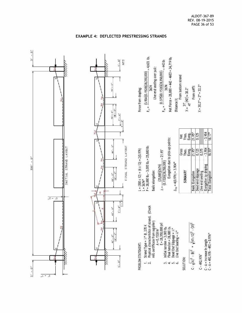
ALDOT-367-89 REV. 08-19-2015
PAGE 36 of 53
EXAMPLE 4: DEFLECTED PRESTRESSING STRANDS
ALDOT-367-89 REV. 08-19-2015
PAGE 37 of 53
11 FORMS 11.1 FORM MATERIALS AND CONFIGURATION
Steel side forms and steel or concrete bottom forms shall be used for casting. Internal forms and void tubes for slabs and piles shall be cardboard, plywood or other approved materials. Forms shall be of sufficient thickness and shall be braced, stiffened and anchored, to maintain the correct alignment and to withstand the forces that result from vibratory placement of the concrete.
Keyways, countersunk keys, and other configurations shown on the plans shall be built into the forms. Tops of headers shall be in the same plane as the top of the side forms. The elevation of the tops of the headers and side forms shall be the same on all forms used in the production of a line of the same or similar types of components.
Void forms used for forming holes in slabs and piles shall be anchored firmly so they will not move during concrete placement. Void forms that are damaged due to improper handling or storage shall not be used. Improper location of the voids may adversely change the structural properties of the member. Members will be rejected if a void is out of position in excess of the allowable tolerance.
Forms shall be designed so that they will not restrict the longitudinal movement of the members when the strands are cut and the prestressing force is transferred to the members.
Stressing frames shall not be used unless approved in writing by the Bridge Engineer prior to the installation of the strands.
11.2 CLEANING AND ASSEMBLY OF FORMS Forms shall be cleaned before each use. Paint and other protective substances that might
cling to the surface of the member shall be removed from the forms. All joints in the forms shall be smooth and tight to avoid undesirable flaws and blemishes
in the finished member. Leakage of mortar will not be permitted. Joints between the soffit, side forms and headers shall be tight. Joints may be sealed with
gaskets of rubber or other suitable materials. Gasket materials may also be used to provide chamfers. Slots and holes in the forms shall be plugged so that the finished member will be smooth.
The alignment of the forms shall be maintained throughout the casting operation. Form alignment and grade shall be checked each time the forms are set.
Headers and side forms shall be adequately secured to maintain the shape and dimensions of the member within the specified tolerances.
11.3 BOND BREAKERS APPLIED TO FORMS. Forms shall be treated with a clear non-staining bond breaking agent that partially dries
and leaves a bond breaking film to prevent the concrete member from sticking to the form. The strength of the member is based on the development of uniform bond of the concrete
to all the reinforcing steel and prestressing strand within the member. Bond breaking substances shall be kept from falling on the reinforcing steel and prestressing strand to make sure that the concrete will bond adequately to the reinforcing steel and prestressing strand.
The bond breaking substance may be applied to the bottom of the form before the reinforcing steel and prestressing strand is placed. Special care shall be taken to prevent the bond breaking substance from getting on the reinforcing steel and prestressing strand when the steel is being placed into position.
The bond breaking substance shall be applied to the side forms before they are set. Special care must be taken to prevent the bond breaking substance on the side forms from getting on the reinforcing steel and prestressing strand during the positioning of the forms. Forms shall not be sprayed with a bond breaking substance after the reinforcing steel and the prestressing strand have been positioned and tensioned.
11.4 MULTIPLE FORMS FOR PRODUCTION LINES Each production line shall be equipped with a complete set of forms so that all members
in a casting line can be cast in one operation. Members shall be cast and cured in a continuous operation. The movement of forms from, or within a production line, will not be permitted until the concrete reaches the compressive strength required for the transfer of the prestressing force (detensioning) to the members.
ALDOT-367-89 REV. 08-19-2015
PAGE 38 of 53
11.5 INSPECTION OF FORMS PRIOR TO CASTING Forms for casting shall be inspected by the QC technician prior to the beginning of casting
operations. Documentation of inspection and maintenance records shall be kept on file by the QC technician. The QA inspector will review the QC technician documentation and will verify that all forms meet the requirements stated in this procedure or shown on the approved drawings prior to the beginning of casting operations.
12 PRESTRESSING STEEL All prestressing steel shall be free of deleterious materials such as grease, oil, wax, dirt, loose
rust, and paint. The presence of these deleterious materials may be detrimental to the bond between steel and concrete. Prestressing steel shall be free of bond breaking substances used on the surfaces of the forms.
Light rust will not be detrimental to the bond of the concrete to the steel. Rust that causes pitting of the steel or cannot be cleaned without abrasion shall not be allowed. Prestressing steel shall be handled at all times in such a manner as to prevent nicks and kinks. Prestressing strands shall not be used if they have nicks, kinks or bends.
Due to the differences in area, possible lay of wire, and/or modulus of elasticity, all strands in a production line shall be from the same manufacturer. Mixing strands from two or more manufacturers shall not be allowed.
Tensioned strands shall be protected from excessive temperatures such as those produced by torches and welding equipment. They shall also be protected from physical damage due to the operation of equipment such as metal grinders and materials handling equipment.
Prestressing steel for use on ALDOT projects shall be clearly marked for type of strand and heat number. Care shall be taken in the storage of prestressing steel to prevent galvanic or battery action which occurs if dissimilar metals are in contact or closely adjacent with an ionized medium common to both.
12.1 STRAND SPLICING Only one approved splice per strand will be allowed in single strand tensioning. This splice
shall not be positioned within the member. Strands which are being spliced shall have the same “twist” or “lay” to avoid unraveling. The slippage of the splice shall be considered in computing the elongation.
For multiple strands tensioning, either all of the strands shall be spliced, or no more than 10 % of them shall be spliced. Splices shall not be in the member. If all of the strands are spliced, the average splice slippage shall be considered in computing the elongation. If 10% or less is spliced, there will be no need to consider slippage.
12.2 WIRE FAILURE IN PRESTRESSING STRANDS Failure of individual wires in a prestressing strand will be acceptable provided that not
more than one wire per strand is broken, the total cross sectional area of broken wires is not more than 2 % of the total cross sectional area of all the strands in a member, and the breakage is not symptomatic of a more extensive distress condition.
13 REINFORCING STEEL Steel reinforcement shall be installed in accordance with the details shown on the plans.
Reinforcement shall be installed within the allowable tolerances for placement. Bar size, bar location, bar spacing, and the spacing in the forms for concrete cover shall be checked by the QC technician and verified by the QA inspector.
Tie wires used to fasten the reinforcing steel in place shall be bent away from what will be the exterior of the member to make sure that required protective cover of concrete will be provided when the concrete is placed.
Reinforcing bars that extend out of the member shall be properly positioned and shall have the proper bar extension as indicated on the plans. Bars extending out of the member shall be cleaned of all mortar and other materials that may interfere with the bonding of these bars to the concrete in the completed structure.
ALDOT-367-89 REV. 08-19-2015
PAGE 39 of 53
14 CONCRETE 14.1 DISTRIBUTION OF CONCRETE MIXTURE DESIGN
If the producer's proposed concrete mixture design is approved for conditional use, the Bureau of Materials and Tests will provide the precast producer with a BMT-75 form containing the approved design. The mixture design will not have a project number designated for the use of the mixture and shall not be used without evaluation by the ALDOT QA inspector. The conditional approval of the mixture design will be valid for a period of four years, but will only be valid if the producer maintains a PCI acceptable plant certification status.
14.2 REQUEST AND USE OF APPROVED MIXTURE DESIGN Prior to the production use of a concrete mixture for casting components for a specific
ALDOT construction project, the producer shall submit a BMT-75 form to the ALDOT QA inspector. The form shall be submitted for review and approval by the ALDOT QA inspector. The producer shall submit this form with the project number, county, and description of the component that will be cast using the mixture. This request for approval to use the mixture shall be submitted a minimum of seven calendar days prior to the use of the concrete mixture.
The QA inspector will review the information on the BMT-75 and verify that the concrete mixture design meets the contract requirements. The QA inspector will also verify that the producer has a current PCI plant certification, and that the concrete supplier has a current National Ready Mixed Concrete Association (NRMCA) certification prior to approval of the mixture for use on the project.
Producers of prestressed concrete bridge members will be listed on List I-10, “Producers of Precast Non-Prestressed and Prestressed Concrete Bridge Members”, in the Materials, Sources, and Devices with Special Acceptance Requirements manual. This list will show the producer’s current certifications and expiration date. Producers of ready mixed concrete will be listed on List I-7, “Portland Cement Concrete Producers”, in the Materials, Sources, and Devices with Special Acceptance Requirements manual. This list will show the concrete producer’s NRMCA certification and expiration date.
The QA inspector will notify the producer if the conditionally approved mixture design is approved for casting the members for the specific project. If the submitted mixture design does not meet the requirements for the specific project, the QA inspector will notify the producer with an explanation of why the mixture is not approved for casting.
Copies of the approved project specific concrete mixture design will be kept in the project files of the Bureau of Materials and Tests, in the QA inspector’s file, and shall also be kept in the QC technician's file at the producer's plant for 5 years after completion of the ALDOT project where the concrete mixture was used.
14.3 CONCRETE BATCHING All batching plants shall meet the requirements given in Section 501 of the Standard
Specifications and ALDOT-352. A certification by the National Ready Mixed Concrete Association (NRMCA) shall be submitted to the Bureau of Materials and Tests to the attention of the Concrete Section prior to start any batching operation.
Concrete batching plants and their operation shall be in conformance with AASHTO M 157.
14.3.1 AGGREGATE MOISTURE CONTROL FOR SCC BATCHING If moisture meters are not used, the free moisture content of aggregates shall
be measured within one hour prior to each day’s batching operations, at 2- hour intervals during continuous batching operations, and at any time a change in moisture content becomes apparent.
14.4 CONVENTIONAL CONCRETE TESTING REQUIRED DURING PRODUCTION 14.4.1 QC RESPONSIBILITY FOR TESTING
The producer’s QC technician shall be responsible for the performance of all concrete sampling and testing. Sampling and testing shall be performed as close as possible to the casting bed in the presence of the QA inspector.
At least one complete set of concrete tests shall be done for each production line for every 50 cubic yards, or fraction thereof, of concrete placed. A set of tests shall consist of air
ALDOT-367-89 REV. 08-19-2015
PAGE 40 of 53
content, slump, temperature and strength measurements. The QA inspector will determine the point of sampling and testing schedule for each line of production.
Fresh concrete will be accepted on the basis of slump, air content, and temperature meeting the requirements given in this procedure and in Section 513. Hardened concrete will be accepted on the basis of compressive strength testing meeting the requirements given in this procedure and in Section 513.
Specific testing requirements for self-consolidating concrete are defined in Article 13.5.
14.4.2 AIR CONTENT The determination of the air content of freshly mixed concrete shall be done
in conformance with the requirements given in AASHTO T 152.
14.4.3 SLUMP The consistency of freshly mixed concrete shall be determined in accordance
with the requirements given in AASHTO T 119. Chemical admixtures may be used to increase the slump of the concrete to a
maximum of 9 inches provided the use of these admixtures is shown on the approved mixture design. The water to total cementitious material ratio shall never be exceeded in order to increase the slump.
14.4.4 TEMPERATURE The temperature of freshly mixed concrete at the time of placing in the forms
shall not be less than 50 ºF or more than 95 ºF. The measurement of the temperature of the concrete shall be in conformance with the requirements given in AASHTO T 309.
14.4.5 CONCRETE COMPRESSIVE STRENGTH TEST CYLINDERS The determination of concrete strength shall be done by the compressive
strength testing of concrete cylinders. Cylinders for the determination of the compressive strength shall be made in accordance with the requirements given in AASHTO T 23 and shall be tested in conformance with the requirements given in AASHTO T 22.
The use of 4 X 8 cylinders may be allowed to determine the 28-day compressive strength of the concrete provided that a correlation comparing 6 X 12 cylinders versus 4 X 8 cylinders was included as part of the mixture design submittal. An adjustment factor equal to or higher than 1.0 shall be applied. The use of 4 X 8 cylinders without a correlation factor may be allowed to determine the release strength of prestressed bridge members if a written request is approved by the Materials and Tests Engineer.
A minimum of 12 standard test cylinders, 6 inch diameter x 12 inch long, or 18 test cylinders, 4 inch diameter x 8 inch long, shall be made for every 50 cubic yards, or fraction thereof, of concrete placed in one production line. The cylinders shall be cured in the exact same manner as the curing of the prestressed component that will be represented by the test cylinders. The cylinders shall be placed as directed by the QA inspector in regions representing the average curing conditions of the members.
Half of the cylinders shall be used to determine if the compressive strength of the concrete is adequate to allow detensioning. Two 6 X 12 or three 4 X 8 cylinders shall be tested at a time. The average compressive strength of the cylinders shall equal or exceed the specified release compressive strength, and none of the cylinder test results shall be below 95% of the specified release compressive strength. The producer's QC technician, in the presence of the QA inspector, shall measure the compressive strength and record the test results.
If the average compressive strength of the cylinders is more than 100 psi below the compressive strength required for detensioning, the members shall be cured an additional two hours for every 100 psi below the required compressive strength. The QA inspector will set the time that will be required for additional curing if the average strength is less than 100 psi below the required strength for detensioning.
Half of the cylinders shall be tested for the determination of the 28-day compressive strength. Two 6 X 12 or three 4 X 8 cylinders shall be tested at a time. The average compressive strength of the cylinders shall equal or exceed the required 28-day compressive strength, and none of the cylinder test results shall be below 95% of the required 28-day compressive strength.
ALDOT-367-89 REV. 08-19-2015
PAGE 41 of 53
The producer's QC technician, in the presence of the QA inspector, shall measure the compressive strength and record the test results even if the required 28-day compressive strength has been achieved at an early age.
The producer shall provide adequate equipment and facilities to test the concrete cylinders on or near the fabrication yard. The testing laboratory may be an AASHTO accredited commercial laboratory or the ALDOT qualified producer's laboratory. The laboratory and laboratory personnel shall be qualified in accordance with the requirements given in ALDOT-405. Calibration of compressive strength testing machines shall be performed at least annually. The calibrating agency shall supply a calibration curve for each testing machine.
14.5 SELF-CONSOLIDATING CONCRETE TESTING REQUIRED DURING PRODUCTION All SCC test specimen molds, air content buckets, and unit weight buckets shall be filled
in one continuously poured lift using a suitable container without vibration, rodding, or tapping. The SCC shall be dropped from a height of 6 inches ± 2.0 inches above the top of the mold or bucket into the center of the container, unless otherwise specified. The SCC shall be struck off level with the top of the mold or bucket.
14.5.1 QC RESPONSIBILITY FOR SCC TESTING The prestressed concrete producer’s QC technician shall be responsible for the
performance of all concrete sampling and testing during production. The Department's QA technician will determine and document the point of sampling and testing and the schedule of testing for each line of production. Sampling and testing shall be performed as close as possible to the casting bed. Fresh concrete will be accepted during concrete placement based on all the tests shown in Item 513.03(c)2.
The air content, temperature, and compressive strength of SCC shall be tested as defined in Article 13.4. A minimum of one complete set of SCC tests shall be done for each production line for every 50 cubic yards, or fraction thereof, of concrete placed. For SCC, a set of tests shall consist of total air content, slump flow, stability assessment, temperature, and strength measurements. Slump flow shall be tested as defined in Subarticle 8.3.1 of this procedure.
14.5.2 STABILITY TESTING The Visual Stability Index (VSI) shall be assigned in accordance with the
requirements of the Appendix of ASTM C 1611. A 4 inch x 6 inch digital color photograph (printed with a minimum resolution of 300 dpi) of the slump flow patty of the SCC shall be kept for documentation purposes.
During production testing, the VSI test shall be the first test used to assess the stability of SCC for quality assurance. The stability of SCC shall be accepted when the VSI test result is 1.0 or less. If the VSI result is greater than 1.0, then the stability of SCC shall be accepted when the sieved fraction is 7.5 % or less for gradation with ½” nominal aggregate size or smaller, or sieved fraction 15 % or less for gradation with ¾” aggregate nominal aggregate size, as determined by the Sieve Stability Test performed in accordance with ALDOT-452.
14.6 CONCRETE PLACEMENT Concrete shall not be placed before the complete assembly of forms, reinforcing steel
and other components are checked by the QA inspector for compliance with the requirements given in this procedure and the specifications. Concrete shall be placed in the forms in accordance with the requirements given in ALDOT-170, Section 501, and in this procedure. Concrete shall be placed continuously and shall not be placed in layers or tiers in order to avoid horizontal or diagonal cold joints.
Concrete shall not be placed if the ambient air temperature is below 40 ºF. All concrete shall be placed and finished during daylight hours. Concrete shall not be placed or finished while raining or lightning.
Adding water to the concrete surface shall not be allowed. If weather conditions are such that evaporation from the surface may cause shrinkage cracking, a water mist shall be sprayed above the concrete surface during and after finishing until the members can be covered.
Multiple batches of SCC may be simultaneously discharged at the same approximate location in the member. Simultaneous opposing flows of SCC shall not be allowed. The form may be topped off by moving the discharge point of the SCC along the length of the member. SCC delivery shall

ALDOT-367-89 REV. 08-19-2015
PAGE 42 of 53
be timed so that consecutive lifts shall combine completely without creating segregation, visible pour lines, or cold joints. Additional loads of SCC shall be placed within 15 minutes from the previous load. If authorized by the ALDOT QA inspector, an SCC load outside the 15 minutes time frame may be placed on top of a previous load. If additional loads of SCC are placed over SCC that was placed more than 15 minutes earlier, then minimal vibration may be applied to the surface of the already placed SCC to minimize the formation of pour lines and cold joints. Minimal vibration shall only be permitted if it does not cause segregation as determined by the QA inspector.
15 CURING Members shall be protected to prevent excessive loss of moisture during the initial set of the
concrete. The initial set of the concrete shall be the point where the concrete has reached a compressive strength of 500 psi when tested in conformance with the requirements given in AASHTO T 197.
After the concrete has reached its initial set, but not less than four hours after the end of the placement of the concrete, the curing of the members shall begin by either the wet curing method or the steam curing method.
15.1 WET CURING Wet curing shall be done for a minimum of three days with burlap or tarpaulin that is kept
continuously saturated with water. If the concrete has not reached the specified detension compressive strength at the end of the minimum three day period, the curing shall be extended until the specified detension compressive strength is achieved. The members shall remain in the forms and not moved until the specified detension compressive strength, as determined by cylinder tests, is achieved but not less than three days from placement of the concrete.
15.2 STEAM CURING Steam curing shall be applied until after the concrete has reached its initial set. The
temperature of the steam shall be increased at a rate of 40 ºF per hour to a temperature not to exceed 160 ºF. This raised temperature shall be maintained for a period of at least 24 hours and until the concrete reaches the specified release compressive strength. If the concrete has not reached the specified detension compressive strength at the end of the minimum 24 hour period, the curing shall be extended until the specified detension compressive strength is achieved. Hot spots shall be avoided and jets of steam shall be positioned so that they do not discharge directly on the members, forms, or test cylinders. The members shall remain in the forms and not moved until the specified detension compressive strength, as determined by cylinder tests, is achieved but not less than 24 hours from placement of the concrete.
Recording temperature sensors shall be used to record the time versus temperature relationship throughout the entire curing period. Temperature sensors shall be cast into the concrete and shall not be attached or placed near reinforcing steel or any other steel. Temperature sensors shall be positioned within a member at the mid-point between parallel surfaces of the member. One temperature sensor shall be used for every 150 feet, or fraction thereof, of cumulative length of members in one casting bed. When one sensor is required, it shall be placed approximately at the mid-point of the casting bed. When two or more temperature sensors are required, they shall be placed at the one third or one fourth points along the casting bed. Adjustments shall be made to the application of the steam so that the temperature measured at any one sensor location in a line of production is kept within the required curing temperature range and within 15 ºF of any other sensor in the casting bed.
15.2.1 MATCH-CURE SYSTEM A match-cure system may be used to match the temperature profile of the
specimens used for testing the release strength of the concrete with the temperature profile of the prestressed bridge members they represent. In order to use the Match-Cure system, the manufacturer of prestressed bridge member shall meet the following requirements:
A written request to the Materials and Testing Engineer for approval to use a match-cure system.
The manufacturer shall submit all match-curing equipment for inspection prior to use. The equipment shall include at a minimum
ALDOT-367-89 REV. 08-19-2015
PAGE 43 of 53
controller(s), match-cure molds, thermocouple wires, and type “T” thermocouple wire connectors.
The proposed procedure intended to be used for the determination of the release strength using the match-cure system.
The manufacture shall submit for approval to the Materials and Tests Engineer a “Work Plan” for the use of match-cure technology. The plan shall include at a minimum the thermocouple wire layout with all connection points clearly labeled, detail of the function of each input/output control unit, layout of the match-cure curing facility, match-cure mold marking designation, test results performed in the system prior to its use, and the referenced thermocouple location for each type of prestressed concrete member.
If there is a temperature deviation greater than 5 °F between the reference temperature profile and the control temperature profile, the determination of the release concrete compressive strength shall be done by the regular method described in Item 13.4.5.
16 DETENSIONING 16.1 CONCRETE STRENGTH REQUIRED BEFORE DETENSIONING
The prestressing tension force shall not be transferred to the member until the concrete has reached the specified transfer (release) compressive strength. The concrete shall be strong enough to withstand the prestressing tension force when the strands are cut loose.
Detensioning shall be done after the concrete has reached the required compressive release strength and immediately following the curing period while the concrete is still warm and moist. If the concrete is permitted to dry and cool for any length of time prior to detensioning, dimensional changes take place which may cause cracks in the concrete due to the restraint caused by the prestressing steel. Forms, ties, inserts, or other devices that may restrict either horizontal or vertical movement of prestressed members shall be stripped, removed, or loosened, prior to detensioning.
16.2 DETENSIONING SEQUENCE Prestressing forces shall be kept symmetrical about the vertical axis of the member during
the detensioning operation. The cutting of the strands shall be in accordance with the sequence shown on the approved shop drawings.
Individual strands shall be released by sawing or heating the strands in accordance with the approved detensioning sequence. The release of each individual strand shall be done simultaneously at all exposed points of the strand along the casting bed.
In multiple strands detensioning, strands are released simultaneously by hydraulic jacks. The total force is taken from the header by the jack, and then released gradually. For members having draped strands no longitudinal movement shall be allowed until the hold-down devices are removed.
16.3 MEASUREMENT OF CAMBER Camber shall be measured and recorded in all members within 24 hours after detensioning
and prior to shipping by the QC technician. The QA inspector will take camber measurements on a minimum of 50% of all the members cast from the same setup and for the same ALDOT project. Camber measurements will be used only to verify consistency among members cast from the same setup and for the same ALDOT project. Camber measurements are not intended to confirm theoretical shop drawing camber; however, significant variations from measured camber and the camber shown on the shop drawings will be reported to the State Bridge Engineer for evaluation.
17 BEARING MATERIALS AND BEARING SURFACES Bearing materials shall be installed and bearing surfaces shall be cast so that the load of the casting
will be uniformly spread over the bearing area. Metal bearing materials shall be braced within the member to prevent misalignment during the
placement of the concrete.
ALDOT-367-89 REV. 08-19-2015
PAGE 44 of 53
The bearing areas where the member will be placed on non-metallic bearing pads shall be finished to a uniform planar surface. This bearing area shall be constructed to so that the member will fit flush on the surface area of the non-metallic bearing pads. These bearing areas shall be cast on unyielding supports to provide full bearing surfaces.
18 SURFACE FINISH All precast prestressed concrete components shall be finished in accordance with the requirements
of Item 513.03(e).
19 HANDLING, STORING AND SHIPPING AASHTO girders shall not be stacked more than two high and concrete piles shall not be stacked
more than three high. Members shall be lifted only near the ends unless shown otherwise on approved shop drawings. Supports (dunnage) shall be placed under the pickups unless otherwise specified on approved shop drawings.
Supports and bracing for the members shall be stable and level. Members shall be repositioned or relocated as required to maintain them in a stable and level condition.
All prestressed concrete bridge members except piles shall be held at the plant for a minimum of 4 days after casting. Piles shall be held at the plant for a minimum of 21 days after casting. All prestressed concrete bridge members shall not be shipped for installation until the minimum 28 day compressive strength is obtained and verified by test cylinders. Prestressed concrete bridge members shall not be shipped until marked by the ALDOT QA inspector as being acceptable for shipping.
All precast prestressed concrete bridge members that have not been installed in the work for a period of 120 days after the placement of concrete in the forms shall be repositioned on the storage yard to make sure that deformation due to creep, shrinkage, load, and uneven support are kept to a minimum. All members shall be stored in a position that will make them accessible to the ALDOT QA inspector at all times. Repositioning of members shall continue every 120 days until members are shipped.
20 DEFECTIVE MEMBERS Repair of defective members shall require the submittal of a proposed repair procedure. Repairs
of defective members shall be serviceable, fully bonded, durable and inconspicuous. Repairs shall be done in the presence of the ALDOT QA inspector. Inadequately repaired components will not be marked as being acceptable for shipment and installation. The repairs of defective members shall be done in accordance with the accepted repair procedure.
20.1 COSMETIC DEFECTS. Cosmetic defects are those that do not have an adverse effect on the structural properties
of the member. Cosmetic defects do not have any adverse effect on the durability and load carrying capacity of the component Cosmetic defects include recesses in beams at the end of diaphragm bars, small holes due to air trapped in the forms (“bug-holes”), holes left by form ties, and other localized defects which do not expose any steel, and are not located in the bearing areas.
Bug-holes larger than ¾ inch in diameter and ½ inch deep shall be filled with mortar and/or an approved repair products. Multiple bug-holes averaging ¼ inch in diameter and ¼ inch in depth covering an area of 1.5 square feet or more shall be filled with mortar and/or an approved product. If the areas affected by bug-holes are to the extent that the repair will not re-establish the cosmetic appearance, the member shall require the application of a Class 2 surface finish. Determination of required repair shall be done by the QA inspector.
If the QA technician considers that the cosmetic defects are extensive the producer will be required to submit a repair procedure for review and approval. A repair procedure for correcting cosmetic defects shall be submitted to the State Materials and Tests Engineer to the attention of the Concrete Section. The proposal shall include diagrams, pictures, dimensions, and location of the damage area; it also shall include a step by step description of the repair procedure with a list of all the materials to be used.
ALDOT-367-89 REV. 08-19-2015
PAGE 45 of 53
20.2 STRUCTURAL DEFECTS Structural defects are those that have an adverse effect on the structural properties of
the member. Structural defects include cracks, exposed strand, spalls and casting errors that may have an adverse effect on the durability and load carrying capacity of the member. There shall be no repair of structural defects without an approval repair procedure. Structural defects shall be analyzed by a Licensed Professional Engineer licensed in the State of Alabama. A repair procedure for correcting structural defect, based on recommendations of the Licensed Professional Engineer, shall be submitted to the State Bridge Engineer for review and approval.
20.3 CRACKS Structural cracks are those which are induced by external forces producing internal
stresses exceeding the tensile strength of the concrete. There shall be no repair of structural cracks without an approval repair procedure. Structural cracks shall be analyzed by a Licensed Professional Engineer licensed in the State of Alabama. A repair procedure for correcting structural cracks, based on recommendations of the Licensed Professional Engineer, shall be submitted to the State Bridge Engineer for review and approval.
Non-structural cracks are those which appear as a result of component materials characteristics, atmospheric effects, and localized constraint effects. Non-structural cracks in girders and piles shall be sealed according to the criteria listed in Table 19-1. A repair procedure for correcting non-structural cracks shall be submitted to the State Materials and Tests Engineer to the attention of the Concrete Section. The proposal shall include diagrams, pictures, dimensions, and location of the damage area; it also shall include a step by step description of the repair procedure with a list of all the materials to be used.
TABLE 19-1: CRITERIA FOR SEALING CRACKS1
NON-AGGRESSIVE ENVIRONMENT2 CRACK SIZE3 LOCATION CORRECTIVE ACTION
≤ 0.012” TOP FLANGE AND WEB OF GIRDERS OR ANY AREA OF PILES
SEAL WITH LOW VISCOSITY EPOXY4
> 0.012” BUT ≤ 0.025” TOP FLANGE AND WEB OF GIRDERS OR ANY AREA OF PILES EPOXY4 INJECTION
> 0.025” ANY AREA OF ANY PRESTRESSED MEMBER STRUCTURALLY ANALYZE ANY SIZE BOTTOM FLANGE OF GIRDERS STRUCTURALLY ANALYZE
ANY SIZE AN AREA WITHIN A MEASURED DISTANCE FROM THE END OF THE MEMBER THAT IS TWICE THE
HEIGHT OF THE GIRDER STRUCTURALLY ANALYZE
AGGRESSIVE ENVIRONMENT2 CRACK SIZE3 LOCATION CORRECTIVE ACTION
≤ 0.006” TOP FLANGE AND WEB OF GIRDERS OR
ANY AREA OF PILES SEAL WITH LOW VISCOSITY EPOXY4
> 0.006” BUT ≤ 0.012 TOP FLANGE AND WEB OF GIRDERS OR
ANY AREA OF PILES EPOXY4 INJECTION
> 0.012” ANY AREA OF ANY PRESTRESSED MEMBER STRUCTURALLY ANALYZE ANY SIZE BOTTOM FLANGE OF GIRDERS STRUCTURALLY ANALYZE
ANY SIZE AN AREA WITHIN A MEASURED DISTANCE FROM THE END OF THE MEMBER THAT IS TWICE THE
HEIGHT OF THE GIRDER STRUCTURALLY ANALYZE
NOTES: 1. THESE GUIDELINES DO NOT APPLY TO CRACKS GENERATED BY BUMPING OR CAUSED BY MISHANDLING OF
MEMBERS. 2. AGGRESSIVE ENVIRONMENT SHALL BE CONSIDERED TO BE A MARINE ENVIRONMENT OR AN ENVIRONMENT WITH
POTENTIAL OF SULFATE OR ACID ATTACK. 3. ALL CRACKS SHALL BE MEASURED AFTER DETENSIONING. 4. ALL EPOXY MATERIALS USED SHALL BE IN ACCORDANCE WITH SECTION 870.03 OF THE SPECIFICATIONS.
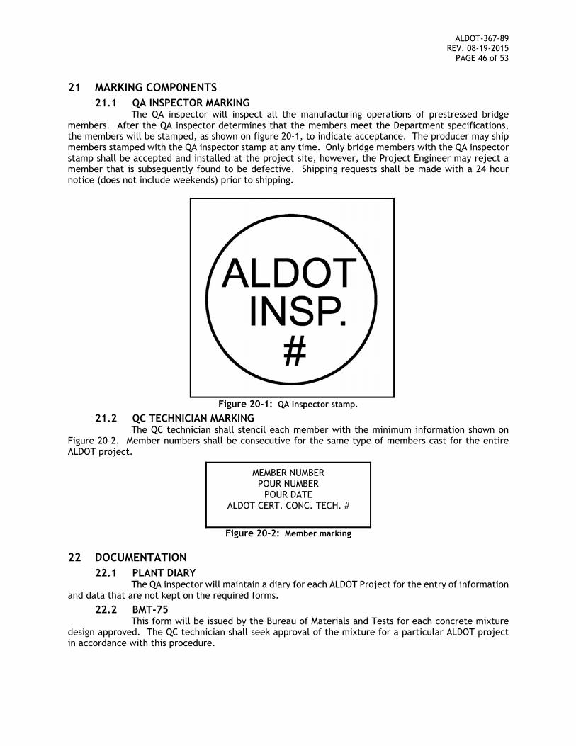
ALDOT-367-89 REV. 08-19-2015
PAGE 46 of 53
21 MARKING COMP0NENTS 21.1 QA INSPECTOR MARKING
The QA inspector will inspect all the manufacturing operations of prestressed bridge members. After the QA inspector determines that the members meet the Department specifications, the members will be stamped, as shown on figure 20-1, to indicate acceptance. The producer may ship members stamped with the QA inspector stamp at any time. Only bridge members with the QA inspector stamp shall be accepted and installed at the project site, however, the Project Engineer may reject a member that is subsequently found to be defective. Shipping requests shall be made with a 24 hour notice (does not include weekends) prior to shipping.
Figure 20-1: QA Inspector stamp.
21.2 QC TECHNICIAN MARKING The QC technician shall stencil each member with the minimum information shown on
Figure 20-2. Member numbers shall be consecutive for the same type of members cast for the entire ALDOT project.
MEMBER NUMBER POUR NUMBER
POUR DATE ALDOT CERT. CONC. TECH. #
Figure 20-2: Member marking
22 DOCUMENTATION 22.1 PLANT DIARY
The QA inspector will maintain a diary for each ALDOT Project for the entry of information and data that are not kept on the required forms.
22.2 BMT-75 This form will be issued by the Bureau of Materials and Tests for each concrete mixture
design approved. The QC technician shall seek approval of the mixture for a particular ALDOT project in accordance with this procedure.
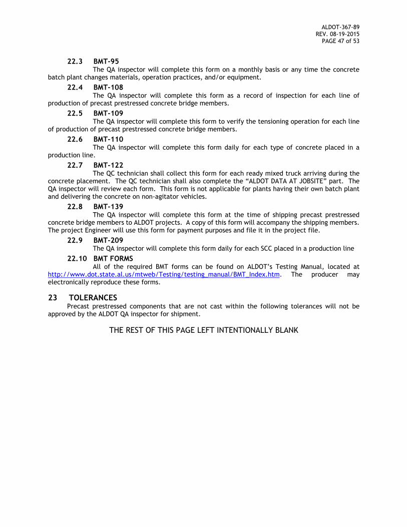
ALDOT-367-89 REV. 08-19-2015
PAGE 47 of 53
22.3 BMT-95 The QA inspector will complete this form on a monthly basis or any time the concrete
batch plant changes materials, operation practices, and/or equipment.
22.4 BMT-108 The QA inspector will complete this form as a record of inspection for each line of
production of precast prestressed concrete bridge members.
22.5 BMT-109 The QA inspector will complete this form to verify the tensioning operation for each line
of production of precast prestressed concrete bridge members.
22.6 BMT-110 The QA inspector will complete this form daily for each type of concrete placed in a
production line.
22.7 BMT-122 The QC technician shall collect this form for each ready mixed truck arriving during the
concrete placement. The QC technician shall also complete the “ALDOT DATA AT JOBSITE” part. The QA inspector will review each form. This form is not applicable for plants having their own batch plant and delivering the concrete on non-agitator vehicles.
22.8 BMT-139 The QA inspector will complete this form at the time of shipping precast prestressed
concrete bridge members to ALDOT projects. A copy of this form will accompany the shipping members. The project Engineer will use this form for payment purposes and file it in the project file.
22.9 BMT-209 The QA inspector will complete this form daily for each SCC placed in a production line
22.10 BMT FORMS All of the required BMT forms can be found on ALDOT’s Testing Manual, located at
http://www.dot.state.al.us/mtweb/Testing/testing_manual/BMT_Index.htm. The producer may electronically reproduce these forms.
23 TOLERANCES Precast prestressed components that are not cast within the following tolerances will not be
approved by the ALDOT QA inspector for shipment.
THE REST OF THIS PAGE LEFT INTENTIONALLY BLANK
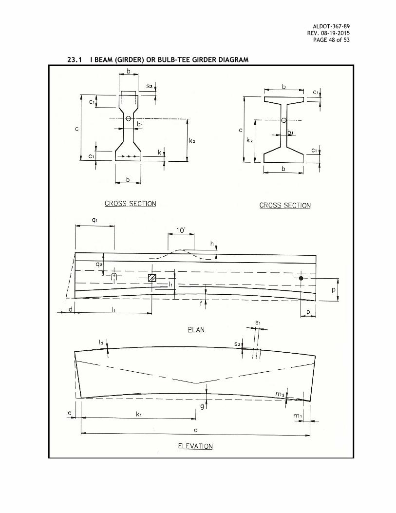
ALDOT-367-89 REV. 08-19-2015
PAGE 48 of 53
23.1 I BEAM (GIRDER) OR BULB-TEE GIRDER DIAGRAM
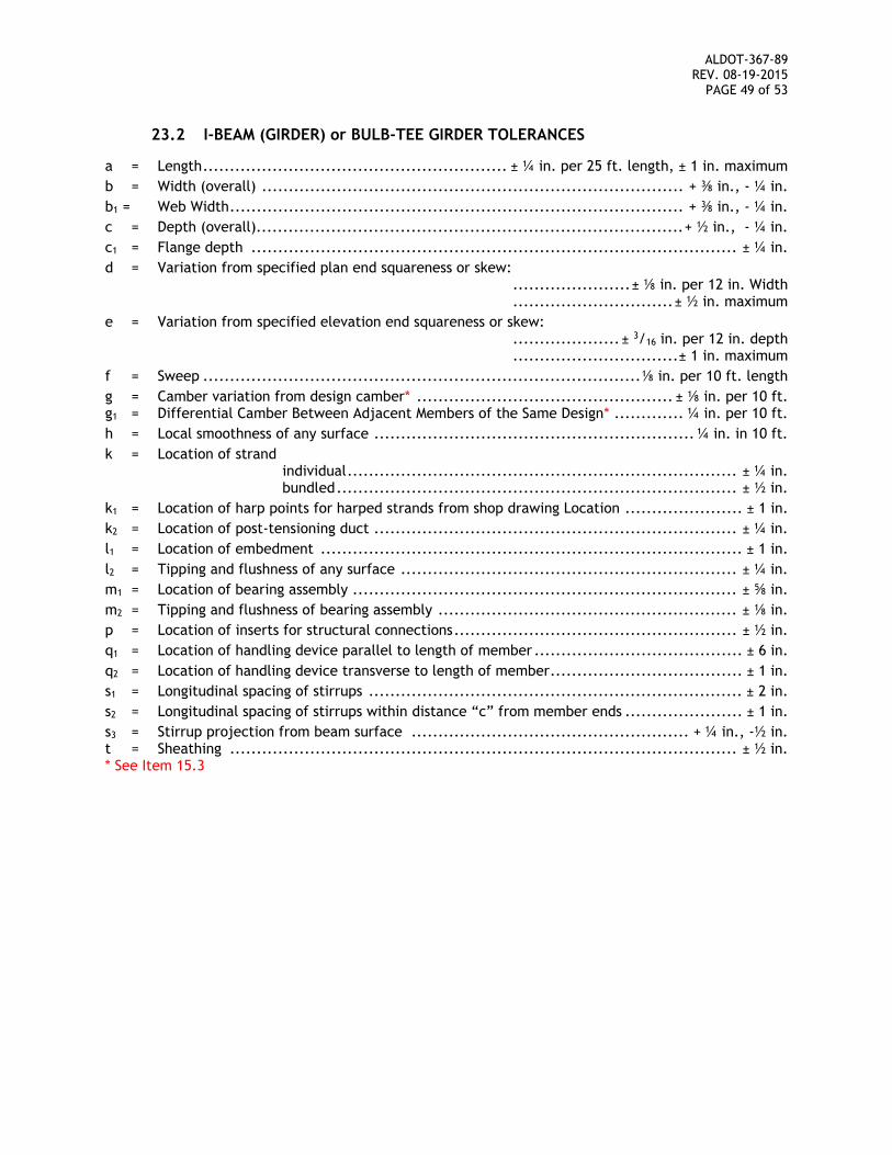
ALDOT-367-89 REV. 08-19-2015
PAGE 49 of 53
23.2 I-BEAM (GIRDER) or BULB-TEE GIRDER TOLERANCES
a = Length ......................................................... ± ¼ in. per 25 ft. length, ± 1 in. maximum
b = Width (overall) ............................................................................... + ⅜ in., - ¼ in.
b1 = Web Width ..................................................................................... + ⅜ in., - ¼ in.
c = Depth (overall)................................................................................ + ½ in., - ¼ in.
c1 = Flange depth ........................................................................................... ± ¼ in.
d = Variation from specified plan end squareness or skew: ...................... ± ⅛ in. per 12 in. Width .............................. ± ½ in. maximum
e = Variation from specified elevation end squareness or skew: .................... ± 3/16 in. per 12 in. depth ............................... ± 1 in. maximum
f = Sweep .................................................................................. ⅛ in. per 10 ft. length
g = Camber variation from design camber* ................................................ ± ⅛ in. per 10 ft. g1 = Differential Camber Between Adjacent Members of the Same Design* ............. ¼ in. per 10 ft.
h = Local smoothness of any surface ............................................................ ¼ in. in 10 ft.
k = Location of strand individual ......................................................................... ± ¼ in. bundled ........................................................................... ± ½ in.
k1 = Location of harp points for harped strands from shop drawing Location ...................... ± 1 in.
k2 = Location of post-tensioning duct .................................................................... ± ¼ in.
l1 = Location of embedment ............................................................................... ± 1 in.
l2 = Tipping and flushness of any surface ............................................................... ± ¼ in.
m1 = Location of bearing assembly ........................................................................ ± ⅝ in.
m2 = Tipping and flushness of bearing assembly ........................................................ ± ⅛ in.
p = Location of inserts for structural connections ..................................................... ± ½ in.
q1 = Location of handling device parallel to length of member ....................................... ± 6 in.
q2 = Location of handling device transverse to length of member .................................... ± 1 in.
s1 = Longitudinal spacing of stirrups ...................................................................... ± 2 in.
s2 = Longitudinal spacing of stirrups within distance “c” from member ends ...................... ± 1 in.
s3 = Stirrup projection from beam surface .................................................... + ¼ in., -½ in. t = Sheathing ............................................................................................... ± ½ in. * See Item 15.3
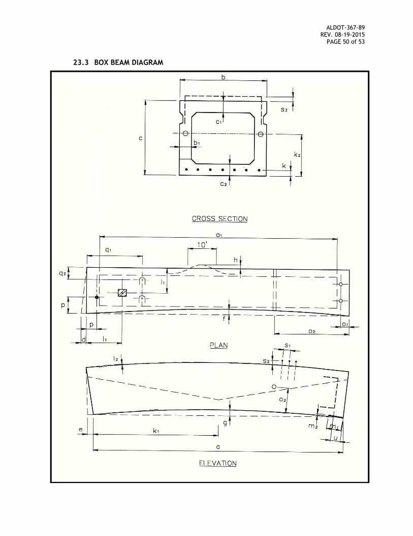
ALDOT-367-89 REV. 08-19-2015
PAGE 50 of 53
23.3 BOX BEAM DIAGRAM
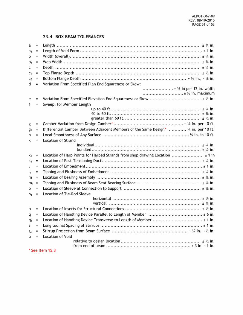
ALDOT-367-89 REV. 08-19-2015
PAGE 51 of 53
23.4 BOX BEAM TOLERANCES
a = Length ................................................................................................... ± ¾ in.
a1 = Length of Void Form .................................................................................... ± 1 in.
b = Width (overall) .......................................................................................... ± ¼ in.
b1 = Web Width .............................................................................................. ± ⅜ in.
c = Depth .................................................................................................... ± ¼ in.
c1 = Top Flange Depth ...................................................................................... ± ½ in.
c2 = Bottom Flange Depth ........................................................................ + ½ in., - ⅛ in.
d = Variation From Specified Plan End Squareness or Skew: ..................... ± ⅛ in per 12 in. width ............................ ± ½ in. maximum
e = Variation From Specified Elevation End Squareness or Skew ................................... ± ½ in.
f = Sweep, for Member Length up to 40 ft. ............................................................. ± ¼ in. 40 to 60 ft. ............................................................. ± ⅜ in. greater than 60 ft. .................................................... ± ½ in.
g = Camber Variation from Design Camber* ................................................ ± ⅛ in. per 10 ft.
g1 = Differential Camber Between Adjacent Members of the Same Design* ............. ¼ in. per 10 ft.
h = Local Smoothness of Any Surface ........................................................... ¼ in. in 10 ft.
k = Location of Strand
individual ......................................................................... ± ¼ in. bundled ........................................................................... ± ¼ in.
k1 = Location of Harp Points for Harped Strands from shop drawing Location ...................... ± 1 in
k2 = Location of Post-Tensioning Duct .................................................................... ± ¼ in.
l = Location of Embedment ................................................................................ ± 1 in.
l1 = Tipping and Flushness of Embedment . ............................................................. ± ¼ in.
m = Location of Bearing Assembly ....................................................................... ± ⅝ in.
m1 = Tipping and Flushness of Beam Seat Bearing Surface ............................................ ± ⅛ in.
o = Location of Sleeve at Connection to Support ..................................................... ± ⅝ in.
o1 = Location of Tie-Rod Sleeve horizontal ............................................................ ± ½ in. vertical ............................................................... ± ⅜ in.
p = Location of Inserts for Structural Connections .................................................... ± ½ in.
q = Location of Handling Device Parallel to Length of Member ..................................... ± 6 in.
q1 = Location of Handling Device Transverse to Length of Member .................................. ± 1 in.
s = Longitudinal Spacing of Stirrups ...................................................................... ± 1 in.
s2 = Stirrup Projection from Beam Surface .................................................... + ¼ in., -½ in.
u = Location of Void relative to design location ....................................................... ± ½ in. from end of beam .......................................................... + 3 In, - 1 in. * See Item 15.3
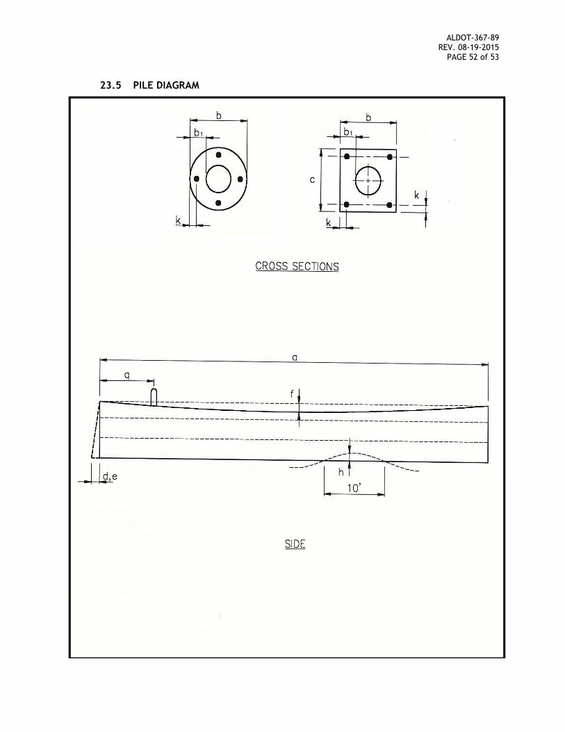
ALDOT-367-89 REV. 08-19-2015
PAGE 52 of 53
23.5 PILE DIAGRAM
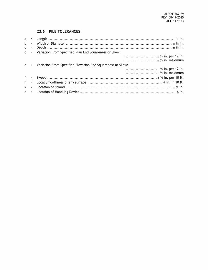
ALDOT-367-89 REV. 08-19-2015
PAGE 53 of 53
23.6 PILE TOLERANCES
a = Length .................................................................................................... ± 1 in.
b = Width or Diameter ..................................................................................... ± ⅜ in. c = Depth .................................................................................................... ± ⅜ in.
d = Variation From Specified Plan End Squareness or Skew: ........................... ± ¼ in. per 12 in. ........................... ± ½ in. maximum
e = Variation From Specified Elevation End Squareness or Skew: .......................... ± ¼ in. per 12 in. .......................... ± ½ in. maximum
f = Sweep ........................................................................................ ± ⅛ in. per 10 ft.
h = Local Smoothness of any surface ........................................................... ¼ in. in 10 ft.
k = Location of Strand ..................................................................................... ± ¼ in.
q = Location of Handling Device ........................................................................... ± 6 in.