AlBeCast Composite Design Guide - Materion · DESIGN GUIDE AlBeCast® COMPOSITE DESIGN GUIDE What...
12
DESIGN GUIDE AlBeCast ® COMPOSITE DESIGN GUIDE What design challenges are you facing today? A guide to designing a more economical and producible investment casting. www.materion.com/AlBeCast
Transcript of AlBeCast Composite Design Guide - Materion · DESIGN GUIDE AlBeCast® COMPOSITE DESIGN GUIDE What...

DESIGN GUIDE
AlBeCast® COMPOSITE DESIGN GUIDE
What design challenges are you facing today?
A guide to designing a more economical and producible investment casting.
www.materion.com/AlBeCast
EXECUTIVE SUMMARYProperty AlBeCast 910® Composite AlBeCast 920® CompositeNominal Beryllium Wt 60% 65%Additional Elements Al, Ni Al, Ag, Co, Ge
Density2.17 g/cm3
[0.078 lbs/in3]2.17 g/cm3
[0.078 lbs/in3]
Coefficient of Thermal Expansion14.6 ppm/C°[8.1 ppm/F°]
14.2 ppm/C°[7.9 ppm/F°]
Modulus of Elasticity in Tension193 GPa
[28.0 Mpsi]202 GPa
[29.3 Mpsi]
Yield Strength (0.2 % Offset)147.5 MPa[21.4 Ksi]
213.7 MPa[31.0 Ksi]
Ultimate Tensile Strength196.5 MPa[28.5 Ksi]
289.6 MPa[42.0 Ksi]
Elongation (1" Gage) 4.7% 3.0%
Materion's AlBeCast® product line is a family of investment cast aluminum-beryllium metal matrix composites that provides designers a net-shape product. This publication is intended to provide a general overview of the aluminum beryllium investment casting process and to assist engineers in designing a more economical and producible investment casting. These are general guidelines and recommendations. They do not represent all of the detail limitations of the process. This document is intended to help engineers understand the aluminum beryllium casting process capabilities, process limitations and typical properties. If there is a particular design issue not covered in this guide, please contact Materion.
KEY REQUIREMENTS:• Identify critical sections and surfaces
• Utilize locator pads to define datums
• Build datums as close to the center-line of the component as possible
• Dimensional tolerance is based on size- ± 0.030" up to 8", ± .060" for the largest parts- ± 0.75 mm up to 200 mm, ± 1.5 mm for the
largest parts
• The maximum AlBeCast composite component weight is 30 lbs [13.6 kg]
• The maximum AlBeCast composite component size is 20" x 20" or 24" diameter [500 mm x 500 mm or 600 mm diameter]
• The ideal wall thickness is between 0.08" and 0.12" [2 mm to 3 mm]
• The minimum wall thickness is 0.06", the maximum typical wall thickness is 1". [Minimum of 1.5 mm, maximum typical of 25 mm]
• Minimize the use of small, deep pockets or blind holes
• Avoid sharp corners and transitions, use generous fillets and radii when possible
• Keep wall thickness constant
• Various AlBeCast material specifications exist for aerospace, commercial and prototype components
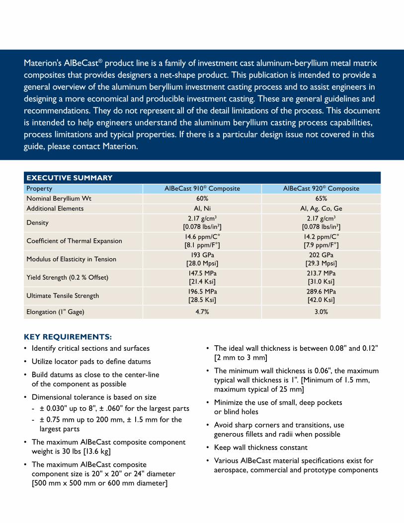
PROCESSMaterion's AlBeCast® product is a two phase material consisting primarily of beryllium intermixed with aluminum. Beryllium provides the alloy with strength and stiffness and aluminum provides ductility. These materials are metal matrix composites in that the microstructure is mixture of a brittle, high strength phase, (Be) and a ductile lower strength phase (Al).
The difficulties in casting AlBeCast material is due to the lack of solubility between beryllium and aluminum, and the fact that beryllium is a very reactive metal. When operating at the high casting temperatures required, molten beryllium will react with most refractories commonly used for crucibles and invest-ment molds. Crucible reactions produce inclusions, while mold reactions cause porosity and poor surface quality. Additionally, AlBeCast materials have a solidifi-cation range of 605 C° [1121 F°]. Materials with such a wide solidification range present unique challenges. AlBeCast composites are produced in a dedicated aluminum beryllium investment casting facility.
Melting and casting are done under vacuum. Materion’s aluminum beryllium investment casting process, including wax injection, shell making, degating, straightening and nondestructive testing (NDT) is very similar to the aluminum investment casting process.
Materion’s aluminum beryllium investment casting process is capable of using either conventional wax patterns or rapid prototype technology. AlBeCast materials are produced by vacuum casting molten metal into hollow “ceramic shells” which reproduce the desired component dimensions. The ceramic shells are manufactured from a unique, non-reactive ceramic formulation. Casting and solidification is conducted under controlled conditions to produce the highest quality casting. Post-cast processing, including deshell-ing, gate removal, straightening, finishing and inspection follow aluminum industry practice. The AlBeCast product line can be repaired, straightened and welded enabling a reduction in costs.
PROTOTYPINGAluminum beryllium castings can be successfully cast using rapid prototype processes. Rapid prototyping processes have advantages and disadvantages over hard tool methods.
PROTOTYPE ADVANTAGES:• Quick - takes typically 6-8 weeks from
electronic file to cast part
• Allows multiple design iterations prior to committing to long lead hard tooling
• Geometrically flexible
• Cost effective for limited runs
PROTOTYPE DISADVANTAGES:• Individual rapid prototype patterns are expensive
• Yields a rougher surface finish than a hard tooled casting
• Thin sections can be difficult to produce using SLA technology
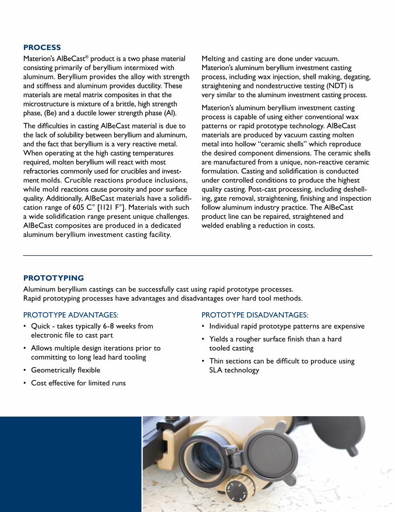
ADVANTAGES OVER A356 ALUMINUM• ~22% lower density
• ~3 times stiffer (modulus of elasticity in tension)
• Up to 10 times better in damping coefficient
• ~40% lower in coefficient of thermal expansion (CTE)
• ~50% higher specific heat
• ~28% higher thermal conductivity
ADVANTAGES OVER BERYLLIUM• ~3 times greater ductility than hot pressed
beryllium with greater damage tolerance
• Castable for complex and precise net shape configurations
• Weldable for defect repair
• Reduced machining and scrap generation
• Reduced environmental processing concerns resulting from reduced waste
• Does not require chemical etching
• Reduced material usage
• Reduced cost
PROPERTIESProperty AlBeCast® 910 Composite AlBeCast® 920 CompositeNominal Beryllium Wt % 60 65Additional Elements Al, Ni Al, Ag, Co, Ge
Density2.17 g/cm3
[0.078 lbs/in3]2.17 g/cm3
[0.078 lbs/in3]
Coefficient of Thermal Expansion14.6 ppm/C°[8.1 ppm/F°]
14.2 ppm/C°[7.9 ppm/F°]
Modulus of Elasticity in Tension193 GPa
[28.0 Mpsi]202 GPa
[29.3 Mpsi]
Yield Strength (0.2 % Offset)147.5 MPa[21.4 Ksi]
213.7 MPa[31.0 Ksi]
Ultimate Tensile Strength196.5 MPa[28.5 Ksi]
289.6 MPa[42.0 Ksi]
Elongation (1" Gage) 4.7% 3.0%
Specific Heat1560 J/Kg C°
[0.36 Btu/lb F°]1250 J/Kg C°
[0.30 Btu/lb F°]
Thermal Conductivity110.0 W/m K°
[64.0 Btu/hr ft F°]105.5 W/m K°
[61.0 Btu/hr ft F°]
Specific Stiffness88.9 GPa cm3/g
[358.9 Mpsi in3/lb]93.1 GPa cm3/g
[375.6 Mpsi in3/lb]Poissons Ratio 0.154 0.20
Specific Strength90.6 MPa cm3/g[365.4 Ksi in3/lb]
133.5 MPa cm3/g[538.5 Ksi in3/lb]
Axial Fatigue (R=-1, Kt=1, 10^7 Cycles)86.2 MPa[12.5 Ksi]
117.2 MPa[17.0 Ksi]
Compressive Yield147.0 MPa[21.3 Ksi]
226.1 MPa[32.8 Ksi]
Pin Double Shear Strength181.0 MPa[26.3 Ksi]
247.5 MPa[35.9 Ksi]
Electrical Conductivity 48% IACS 40% IACS
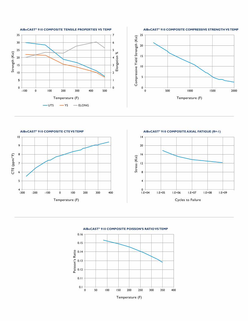
AlBeCAST® 910 COMPOSITE TENSILE PROPERTIES VS TEMP
-100 0 100 200 300 400 500
Temperature (F)
Stre
ngth
(K
si)
Elo
ngat
ion
%
5
0 0
5 1
10 2
15 3
25 5
30 6
35 7
20 4
UTS YS ELONG
AlBeCAST® 910 COMPOSITE COMPRESSIVE STRENGTH VS TEMP
0 500 1000 1500 2000
Temperature (F)
Co
mpr
essi
ve Y
ield
Str
engt
h (K
si)
0
5
10
15
20
25
AlBeCAST® 910 COMPOSITE CTE VS TEMP
-300 -200 -100 0 100 300200 400
Temperature (F)
CT
E (p
pm/°
F)
4
5
6
7
8
9
10
AlBeCAST® 910 COMPOSITE POISSON’S RATIO VS TEMP
0 50 100 150 200 350300250
Temperature (F)
Pois
son’
s R
atio
0.1
0.11
0.12
0.13
0.14
0.15
0.16
AlBeCAST® 910 COMPOSITE AXIAL FATIGUE (R=-1)
1.E+04 1.E+05 1.E+06 1.E+07 1.E+08 1.E+09
Cycles to Failure
Stre
ss (
Ksi
)
0
4
8
12
16
20
14
400
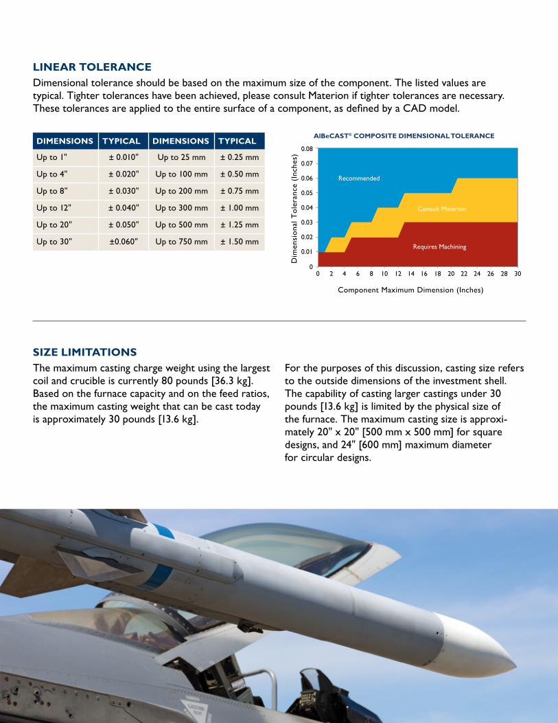
AlBeCAST® COMPOSITE DIMENSIONAL TOLERANCE
0 2 4 6 8 10 12 14 16 18 20 22 24 26 28
Component Maximum Dimension (Inches)
Dim
ensi
ona
l To
lera
nce
(Inc
hes)
0
0.01
0.02
0.03
0.04
0.05
0.06
0.07
0.08
30
Recommended
Consult Materion
Requires Machining
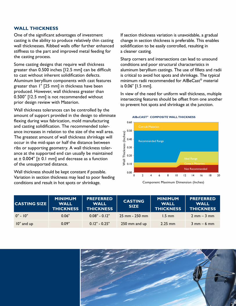
AlBeCAST® COMPOSITE WALL THICKNESS
0 2 4 6 8 10 12 14 16 18
Component Maximum Dimension (Inches)
Wal
l Thi
ckne
ss (
Inch
es)
0.00
0.10
0.20
0.30
0.40
0.50
0.60
20
Consult Materion
Recommended Range
Ideal Range
Consult Materion
Not Recommended
AlBeCAST® 910 COMPOSITE TENSILE PROPERTIES VS TEMP
-100 0 100 200 300 400 500
Temperature (F)
Stre
ngth
(K
si)
Elo
ngat
ion
%
5
0 0
5 1
10 2
15 3
25 5
30 6
35 7
20 4
UTS YS ELONG
AlBeCAST® 910 COMPOSITE COMPRESSIVE STRENGTH VS TEMP
0 500 1000 1500 2000
Temperature (F)
Co
mpr
essi
ve Y
ield
Str
engt
h (K
si)
0
5
10
15
20
25
AlBeCAST® 910 COMPOSITE CTE VS TEMP
-300 -200 -100 0 100 300200 400
Temperature (F)
CT
E (p
pm/°
F)
4
5
6
7
8
9
10
AlBeCAST® 910 COMPOSITE POISSON’S RATIO VS TEMP
0 50 100 150 200 350300250
Temperature (F)
Pois
son’
s R
atio
0.1
0.11
0.12
0.13
0.14
0.15
0.16
AlBeCAST® 910 COMPOSITE AXIAL FATIGUE (R=-1)
1.E+04 1.E+05 1.E+06 1.E+07 1.E+08 1.E+09
Cycles to Failure
Stre
ss (
Ksi
)
0
4
8
12
16
20
14
400
AlBeCAST® COMPOSITE DIMENSIONAL TOLERANCE
0 2 4 6 8 10 12 14 16 18 20 22 24 26 28
Component Maximum Dimension (Inches)
Dim
ensi
ona
l To
lera
nce
(Inc
hes)
0
0.01
0.02
0.03
0.04
0.05
0.06
0.07
0.08
30
Recommended
Consult Materion
Requires Machining
AlBeCAST® COMPOSITE WALL THICKNESS
0 2 4 6 8 10 12 14 16 18
Component Maximum Dimension (Inches)
Wal
l Thi
ckne
ss (
Inch
es)
0.00
0.10
0.20
0.30
0.40
0.50
0.60
20
Consult Materion
Recommended Range
Ideal Range
Consult Materion
Not Recommended

DIMENSIONAL RECOMMENDATIONSThese dimensional recommendations are applicable to all AlBeCast® materials although the AlBeCast 910 product line can be less difficult to cast therefore allowing some variation in design.
Aluminum beryllium castings have dimensional stability on par with standard aluminum investment castings. As the size of the feature increases, so will the dimensional variation. If features require tighter tolerances, they can be machined into the product if sufficient clean stock is available.
Identification and design of critical features and surfaces is vital for cost-effective production of aluminum beryllium cast components. The cost of a casting increases in relation to the complexity of the design and the level of precision required.
Contact Materion to review critical component features early in the design process.
FACTORS INFLUENCING LINEAR TOLERANCES • Component size
• Component geometry
• Wall thickness
• Wax injection tool
• Wax processing and assembly
• Casting feed design
• Shell processing and shell type
• Metal pouring conditions
• Mold removal procedures
• Post casting processing
DATUM SETUPAluminum beryllium castings are dimensioned from “datum” planes. Proper selection and orientations of the casting datum planes is critical to cost-effective casting inspection and machining.
A datum is simply a plane defining the zero from which all dimensions are measured. For casting design, it is typical to choose three datum planes at right angles to each other. In this way all dimen-sions in all three orthogonal directions can be uniquely defined without ambiguity.
Six points are required to define the position of a component with orthogonal datum planes. The 3,2,1 arrangement uses three points to define datum A, two points to define datum B and one point to define datum C. The points defining each datum should be spaced as widely as possible to maximize accuracy. However, in order to reduce the errors, the datum planes themselves should be as close to the center of the part as possible.
Location points can be cast into the surface of the part to define the points on which the datums are located. These points may be any size, but are often designed as a cylindrical boss, 0.3" in diameter, 0.06" tall. These location points should also serve as clamp points for any machining operation which is why often times the location points are established on tooling lug features.
Most cylindrical parts do not fall neatly into the classical six-point location system. The best method of defining a cylindrical part utilizes a three-jaw chuck to center the major diameter of the part. This chuck is the equivalent of a two points, since it defines an axis. Three points longitudinally abutting the jaws define a plane at a right angle to the central axis. A final “clocking” point completes this datum scheme.
AlBeCAST® 910 COMPOSITE TENSILE PROPERTIES VS TEMP
-100 0 100 200 300 400 500
Temperature (F)
Stre
ngth
(K
si)
Elo
ngat
ion
%
5
0 0
5 1
10 2
15 3
25 5
30 6
35 7
20 4
UTS YS ELONG
AlBeCAST® 910 COMPOSITE COMPRESSIVE STRENGTH VS TEMP
0 500 1000 1500 2000
Temperature (F)
Co
mpr
essi
ve Y
ield
Str
engt
h (K
si)
0
5
10
15
20
25
AlBeCAST® 910 COMPOSITE CTE VS TEMP
-300 -200 -100 0 100 300200 400
Temperature (F)
CT
E (p
pm/°
F)
4
5
6
7
8
9
10
AlBeCAST® 910 COMPOSITE POISSON’S RATIO VS TEMP
0 50 100 150 200 350300250
Temperature (F)
Pois
son’
s R
atio
0.1
0.11
0.12
0.13
0.14
0.15
0.16
AlBeCAST® 910 COMPOSITE AXIAL FATIGUE (R=-1)
1.E+04 1.E+05 1.E+06 1.E+07 1.E+08 1.E+09
Cycles to Failure
Stre
ss (
Ksi
)
0
4
8
12
16
20
14
400
AlBeCAST® COMPOSITE DIMENSIONAL TOLERANCE
0 2 4 6 8 10 12 14 16 18 20 22 24 26 28
Component Maximum Dimension (Inches)D
imen
sio
nal T
ole
ranc
e (I
nche
s)
0
0.01
0.02
0.03
0.04
0.05
0.06
0.07
0.08
30
Recommended
Consult Materion
Requires Machining
AlBeCAST® COMPOSITE WALL THICKNESS
0 2 4 6 8 10 12 14 16 18
Component Maximum Dimension (Inches)
Wal
l Thi
ckne
ss (
Inch
es)
0.00
0.10
0.20
0.30
0.40
0.50
0.60
20
Consult Materion
Recommended Range
Ideal Range
Consult Materion
Not Recommended
DIMENSIONS TYPICAL DIMENSIONS TYPICAL
Up to 1" ± 0.010" Up to 25 mm ± 0.25 mm
Up to 4" ± 0.020" Up to 100 mm ± 0.50 mm
Up to 8" ± 0.030" Up to 200 mm ± 0.75 mm
Up to 12" ± 0.040" Up to 300 mm ± 1.00 mm
Up to 20" ± 0.050" Up to 500 mm ± 1.25 mm
Up to 30" ±0.060" Up to 750 mm ± 1.50 mm
SIZE LIMITATIONSThe maximum casting charge weight using the largest coil and crucible is currently 80 pounds [36.3 kg]. Based on the furnace capacity and on the feed ratios, the maximum casting weight that can be cast today is approximately 30 pounds [13.6 kg].
For the purposes of this discussion, casting size refers to the outside dimensions of the investment shell. The capability of casting larger castings under 30 pounds [13.6 kg] is limited by the physical size of the furnace. The maximum casting size is approxi-mately 20" x 20" [500 mm x 500 mm] for square designs, and 24" [600 mm] maximum diameter for circular designs.
LINEAR TOLERANCEDimensional tolerance should be based on the maximum size of the component. The listed values are typical. Tighter tolerances have been achieved, please consult Materion if tighter tolerances are necessary. These tolerances are applied to the entire surface of a component, as defined by a CAD model.
AlBeCAST® 910 COMPOSITE TENSILE PROPERTIES VS TEMP
-100 0 100 200 300 400 500
Temperature (F)
Stre
ngth
(K
si)
Elo
ngat
ion
%
5
0 0
5 1
10 2
15 3
25 5
30 6
35 7
20 4
UTS YS ELONG
AlBeCAST® 910 COMPOSITE COMPRESSIVE STRENGTH VS TEMP
0 500 1000 1500 2000
Temperature (F)
Co
mpr
essi
ve Y
ield
Str
engt
h (K
si)
0
5
10
15
20
25
AlBeCAST® 910 COMPOSITE CTE VS TEMP
-300 -200 -100 0 100 300200 400
Temperature (F)
CT
E (p
pm/°
F)
4
5
6
7
8
9
10
AlBeCAST® 910 COMPOSITE POISSON’S RATIO VS TEMP
0 50 100 150 200 350300250
Temperature (F)
Pois
son’
s R
atio
0.1
0.11
0.12
0.13
0.14
0.15
0.16
AlBeCAST® 910 COMPOSITE AXIAL FATIGUE (R=-1)
1.E+04 1.E+05 1.E+06 1.E+07 1.E+08 1.E+09
Cycles to Failure
Stre
ss (
Ksi
)
0
4
8
12
16
20
14
400
AlBeCAST® COMPOSITE DIMENSIONAL TOLERANCE
0 2 4 6 8 10 12 14 16 18 20 22 24 26 28
Component Maximum Dimension (Inches)
Dim
ensi
ona
l To
lera
nce
(Inc
hes)
0
0.01
0.02
0.03
0.04
0.05
0.06
0.07
0.08
30
Recommended
Consult Materion
Requires Machining
AlBeCAST® COMPOSITE WALL THICKNESS
0 2 4 6 8 10 12 14 16 18
Component Maximum Dimension (Inches)
Wal
l Thi
ckne
ss (
Inch
es)
0.00
0.10
0.20
0.30
0.40
0.50
0.60
20
Consult Materion
Recommended Range
Ideal Range
Consult Materion
Not Recommended
WALL THICKNESSOne of the significant advantages of investment casting is the ability to produce relatively thin casting wall thicknesses. Ribbed walls offer further enhanced stiffness to the part and improved metal feeding for the casting process.
Some casting designs that require wall thickness greater than 0.500 inches [12.5 mm] can be difficult to cast without inherent solidification defects. Aluminum beryllium components with cast features greater than 1" [25 mm] in thickness have been produced. However, wall thickness greater than 0.500" [12.5 mm] is not recommended without prior design review with Materion.
Wall thickness tolerances can be controlled by the amount of support provided in the design to eliminate flexing during wax fabrication, mold manufacturing and casting solidification. The recommended toler-ance increases in relation to the size of the wall area. The greatest amount of wall thickness shrinkage will occur in the mid-span or half the distance between ribs or supporting geometry. A wall thickness toler-ance at the supported end can usually be maintained at ± 0.004" [± 0.1 mm] and decrease as a function of the unsupported distance.
Wall thickness should be kept constant if possible. Variation in section thickness may lead to poor feeding conditions and result in hot spots or shrinkage.
If section thickness variation is unavoidable, a gradual change in section thickness is preferable. This enables solidification to be easily controlled, resulting in a cleaner casting.
Sharp corners and intersections can lead to unsound conditions and poor structural characteristics in aluminum beryllium castings. The use of fillets and radii is critical to avoid hot spots and shrinkage. The typical minimum radii recommended for AlBeCast® material is 0.06" [1.5 mm].
In view of the need for uniform wall thickness, multiple intersecting features should be offset from one another to prevent hot spots and shrinkage at the junction.
CASTING SIZEMINIMUM
WALL THICKNESS
PREFERRED WALL
THICKNESS
CASTING SIZE
MINIMUM WALL
THICKNESS
PREFERRED WALL
THICKNESS
0" - 10" 0.06" 0.08" - 0.12" 25 mm - 250 mm 1.5 mm 2 mm – 3 mm
10" and up 0.09" 0.12" - 0.25" 250 mm and up 2.25 mm 3 mm – 6 mm
FILLETS AND RADIILarger fillet and corner radii are required in aluminum beryllium castings in comparison to conventional investment cast aluminum alloys due to the solidifica-tion rate differences between the materials. The larger fillet and corner radii will minimize
micro-shrinkage and heat affected zone defects at corners. Recommended fillet and corner radii are 0.06" [1.5mm] minimum, however larger is typically preferred.
CAST HOLES OR CAVITIESHoles from 0.25" [6 mm] diameter and larger can be cast directly in AlBeCast® material with a maxi-mum through-hole depth less than or equal to their diameter. Holes larger than 1.5" [38 mm] diameter may have increased depth, however, please review with Materion.
Maximum blind hole depth is half of the holes diameter. In some cases, it is more cost effective to produce these features by machining after casting due to the position variability of casting directly. The roundness of cast holes is influenced by the material surrounding it. If the mass of material around the hole is uneven, the hole roundness will decrease.
Long holes with small diameters will form weak ceramic cores during the shell process. These weak cores have a tendency to break during casting, leaving excess metal in the hole and shell fragments in other areas of the casting. In addition, removing shell mate-rial from long narrow passageways will add extra time and labor to remove the shell. Therefore machining the holes later may prove more cost effective.
Tapered holes or cavities can be produced, however, the direction of the hole or cavity taper will greatly influence the cost of tooling. Positive tapers are more economical since tooling cost is lower while negative tapers prevent removal of wax patterns directly and require complex tooling.
SURFACE FINISHTypical surface roughness on aluminum beryllium castings is less than 175 RMS using wax injection tooling. When a surface finish less than 175 RMS is required, machine stock may be added to the casting design to accommodate for a machining operation. This highlights the need for a review of critical surfaces early in the design process, so that machine stock may be incorporated in the casting design.
Rapid prototypes and soft tool fabricated patterns will have typical surface finishes of 175 RMS or greater. The increase in surface roughness must be considered when using these pattern fabrication methods.
ANGLESAngular tolerances of +/- 0.5 degrees are normal.
DRAFTInvestment casting does not require any draft tolerance.
ROUNDNESSGeneral linear tolerances may be held for diameter.
CONCENTRICITY The general section thickness tolerance applies for concentricity.
SPECIFICATIONS Materion's AlBeCast® product line consists of three product specifications; Aerospace, Commercial and Prototype. These specifications define the required properties, inspections and quality assurances for their respective grade. These specifications will be provided upon request to Materion.
MACHINING AlBeCast material is fabricated using processes which mirror standard aluminum industry prac-tices. Machining, joining, bending and coating operations can all be conducted on this material. The principle difference between aluminum and aluminum-beryllium materials during these operations is the need to control, collect, and remove any beryllium-containing particles generated during the fabrication operations.
AlBeCast composites can be conventionally machined using standard high-speed steel cutters. Standard feeds and speeds may be used, but due to the abrasive nature of the beryllium, the material is more abrasive than aluminum alloys. Cutter life is approximately 60 percent of that expected for similar cuts in aluminum. For that reason, carbide cutting tools are recommended. Using standard geometry C-2 tungsten carbide cutting tools, machining speeds as high as 600 surface feet per minute [183 m/min] with a 0.006" [0.15 mm] chip load have been used with success in milling operations.
Machining with coolants is recommended and most coolants suitable for aluminum can be used with AlBeCast composite. It may be required to stress relieve components during or after machining. A simple stress relief of 500°C [925°F] for two hours followed by a furnace cool is sufficient to remove these stresses. Mechanical properties are unchanged by this process.
FASTENING Inserts and pinning are compatible with AlBeCast material. Aluminum insert information should be used, with the usual care taken near edges to avoid breakout. Inserts should be installed as part of the machining and finishing process.
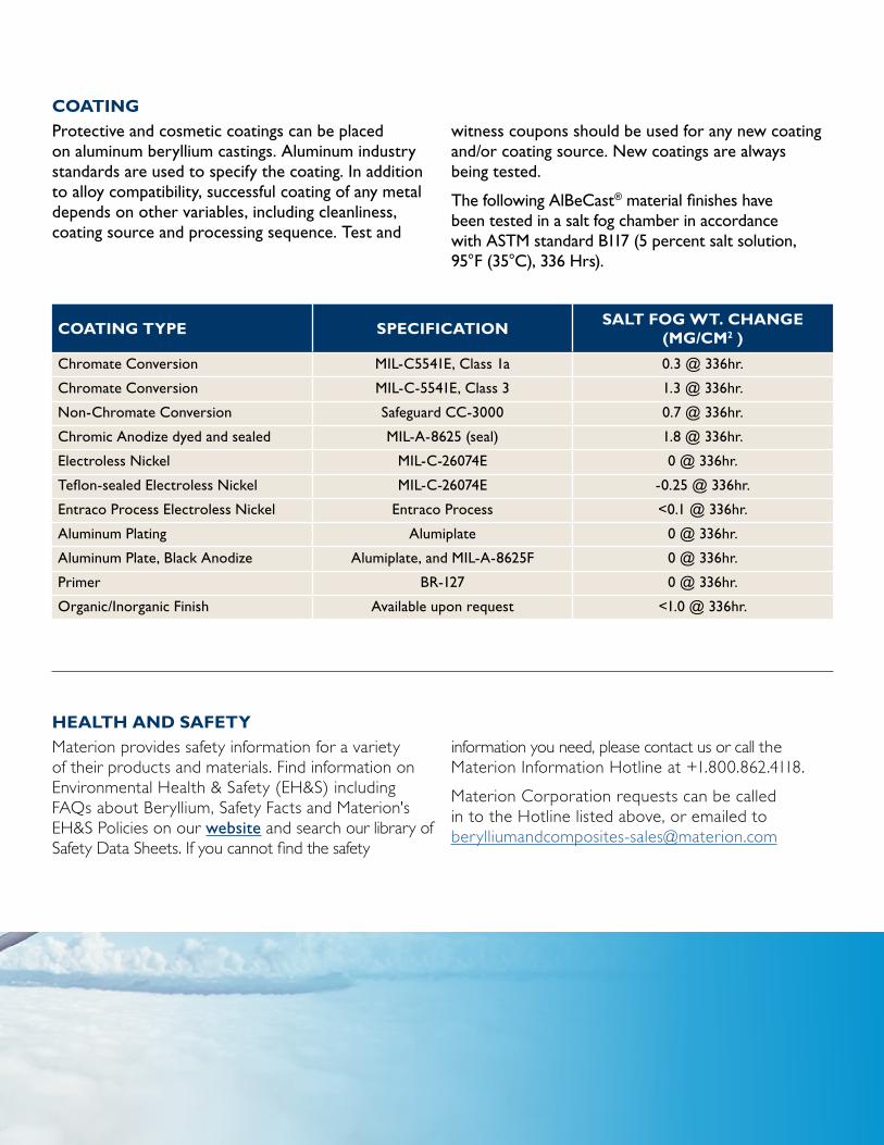
COATING Protective and cosmetic coatings can be placed on aluminum beryllium castings. Aluminum industry standards are used to specify the coating. In addition to alloy compatibility, successful coating of any metal depends on other variables, including cleanliness, coating source and processing sequence. Test and
witness coupons should be used for any new coating and/or coating source. New coatings are always being tested.
The following AlBeCast® material finishes have been tested in a salt fog chamber in accordance with ASTM standard B117 (5 percent salt solution, 95°F (35°C), 336 Hrs).
COATING TYPE SPECIFICATIONSALT FOG WT. CHANGE
(MG/CM2 )
Chromate Conversion MIL-C5541E, Class 1a 0.3 @ 336hr.
Chromate Conversion MIL-C-5541E, Class 3 1.3 @ 336hr.
Non-Chromate Conversion Safeguard CC-3000 0.7 @ 336hr.
Chromic Anodize dyed and sealed MIL-A-8625 (seal) 1.8 @ 336hr.
Electroless Nickel MIL-C-26074E 0 @ 336hr.
Teflon-sealed Electroless Nickel MIL-C-26074E -0.25 @ 336hr.
Entraco Process Electroless Nickel Entraco Process <0.1 @ 336hr.
Aluminum Plating Alumiplate 0 @ 336hr.
Aluminum Plate, Black Anodize Alumiplate, and MIL-A-8625F 0 @ 336hr.
Primer BR-127 0 @ 336hr.
Organic/Inorganic Finish Available upon request <1.0 @ 336hr.
HEALTH AND SAFETY Materion provides safety information for a variety of their products and materials. Find information on Environmental Health & Safety (EH&S) including FAQs about Beryllium, Safety Facts and Materion's EH&S Policies on our website and search our library of Safety Data Sheets. If you cannot find the safety
information you need, please contact us or call the Materion Information Hotline at +1.800.862.4118.
Materion Corporation requests can be called in to the Hotline listed above, or emailed to [email protected]
Contact Information For more information, please call 419-862-4216
or visit materion.com/AlBeCast