a.l. mercado Pulsed laser deposition vs. matrix assisted...
9
DOI: 10.1007/s00339-004-2994-2 Appl. Phys. A 81, 591–599 (2005) Materials Science & Processing Applied Physics A a.l. mercado c.e. allmond j.g. hoekstra j.m. fitz-gerald ✉ Pulsed laser deposition vs. matrix assisted pulsed laser evaporation for growth of biodegradable polymer thin films University of Virginia, Dept. of Materials Science and Engineering, 116 Engineer’s Way, Charlottesville, VA 22904-4745, USA Received: 20 April 2004/Accepted: 20 July 2004 Published online: 30 September 2004 • © Springer-Verlag 2004 ABSTRACT Thin films of poly (lactide-co-glycolide) (PLGA), a biodegradable polymer, were deposited on Si wafers by both conventional pulsed laser deposition (PLD) and matrix assisted pulsed laser evaporation (MAPLE) using chloroform (CHCl 3 ) as a matrix solvent. This research represents an initial study to investigate the deposition characteristics of each technique at comparable conditions to gain insight into the transport and degradation mechanisms of each approach. The deposited ma- terials were characterized by scanning electron microscopy (SEM), Fourier transform infrared spectroscopy (FTIR), pro- ton nuclear magnetic resonance ( 1 H NMR), and gel permeation chromatography (GPC) with refractive index (RI) detection. While FTIR and NMR results do not show a measurable de- parture from the native, in sharp contrast GPC results show a significant change (up to 95%) in molecular weight for both deposition methods. This result makes it clear that it is possible to overlook substantial degradation when incomplete chemical analysis is conducted. Optical transmission measurements of the starting MAPLE targets yielded laser penetration depths on the order of 0.362 cm and 0.209 cm for pure CHCl 3 and 1 wt. % PLGA in CHCl 3 , respectively. Straightforward application of the Beer–Lambert law for laser energy deposition predicts a negligible tempera- ture rise of less than 1 K at the target surface, which is in clear contradiction with ablation rates of 1.85 µ m/pulse experimen- tally measured for polymer loaded samples. With an ablation process of this magnitude, the material ejection is likely due to contributions of nonlinear or non-homogeneous laser light absorption rather than evaporation. Severe non-uniformity of the final surface morphologies of the MAPLE films, similar to solvent wicking artifacts found in spin casting supports the spallation scenario in MAPLE. PACS 81.15.Fg; 79.20.Ds; 78.66.Qn; 42.70Jk 1 Introduction To intelligently design active and passive organic thin film materials for application in next generation medicine and electronics requires control over both chemical and struc- tural film properties. In many situations, it will be necessary ✉ Fax: +1-434-982-5660, E-mail: [email protected] to deposit films discretely with uniformity containing single or multilayer structures of organic or polymeric materials, homogeneous composite materials, or materials with graded compositions, which is the case with the electronic materials industry. Thin films of polymeric, inorganic and organic ma- terials play an important role in batteries, high performance dielectrics, optical data storage, optical communications and displays based on organic electroluminescent materials [1–7]. Polymer and organic coatings are essential for the fabrication of chemical and biochemical sensors [8, 9], and in biomedical applications ranging from passive films for prosthetic devices to coatings for targeted drug delivery systems [10–13]. Thin films of specific organic materials have been pro- cessed via several non-vacuum routes ranging from conven- tional methods such as spin casting, electrochemical depo- sition, dip coating, solvent evaporation, aerosol coating, to plasma and thermal evaporation [14–19]. For example, recent applications of conjugated polymers to optical and optoelec- tronic devices require the formation of thin polymer films of high quality (retained functionality, thickness, morphology, etc.) [20]. Although spin casting has been widely used, this technique is limited to soluble polymers possessing excel- lent processibility. Moreover, the volume dilution of the op- tically active main chains in the derivative forms modified for solubility results in reduced linear and non-linear optical responses as compared with their parent polymers [21, 22]. Along with the rapidly developing field of plasma polymer- ization [23], several other vacuum methods have been ap- plied to thin polymer film preparation: electron beam irradi- ation [24, 25], ultraviolet (UV) light vapor irradiation [26, 27], thermally assisted vacuum evaporation [28], and by polymer sputtering [29]. However these can only be used in special cases where polymers with a low molecular weight evapo- rate as polymer units and condense on the substrate with- out a reaction. When heated to the evaporation temperature most polymers are fragmented, these gaseous fragments “con- dense” on the substrate without creating a proper polymer network. While the use of high energies and temperatures in plasma processing and UV curing of fragile polymers is gen- erally prohibitive [30–32], two laser based methods have also emerged onto the polymer deposition field, namely pulsed laser deposition (PLD) and matrix assisted pulsed laser evap- oration (MAPLE).
Transcript of a.l. mercado Pulsed laser deposition vs. matrix assisted...

DOI: 10.1007/s00339-004-2994-2
Appl. Phys. A 81, 591–599 (2005)
Materials Science & ProcessingApplied Physics A
a.l. mercadoc.e. allmondj.g. hoekstraj.m. fitz-gerald�
Pulsed laser deposition vs. matrix assistedpulsed laser evaporation for growthof biodegradable polymer thin filmsUniversity of Virginia, Dept. of Materials Science and Engineering, 116 Engineer’s Way,Charlottesville, VA 22904-4745, USA
Received: 20 April 2004/Accepted: 20 July 2004Published online: 30 September 2004 • © Springer-Verlag 2004
ABSTRACT Thin films of poly (lactide-co-glycolide) (PLGA),a biodegradable polymer, were deposited on Si wafers by bothconventional pulsed laser deposition (PLD) and matrix assistedpulsed laser evaporation (MAPLE) using chloroform (CHCl3)as a matrix solvent. This research represents an initial studyto investigate the deposition characteristics of each techniqueat comparable conditions to gain insight into the transport anddegradation mechanisms of each approach. The deposited ma-terials were characterized by scanning electron microscopy(SEM), Fourier transform infrared spectroscopy (FTIR), pro-ton nuclear magnetic resonance (1H NMR), and gel permeationchromatography (GPC) with refractive index (RI) detection.While FTIR and NMR results do not show a measurable de-parture from the native, in sharp contrast GPC results showa significant change (up to 95%) in molecular weight for bothdeposition methods. This result makes it clear that it is possibleto overlook substantial degradation when incomplete chemicalanalysis is conducted.
Optical transmission measurements of the starting MAPLEtargets yielded laser penetration depths on the order of 0.362 cmand 0.209 cm for pure CHCl3 and 1 wt. % PLGA in CHCl3,respectively. Straightforward application of the Beer–Lambertlaw for laser energy deposition predicts a negligible tempera-ture rise of less than 1 K at the target surface, which is in clearcontradiction with ablation rates of 1.85 µm/pulse experimen-tally measured for polymer loaded samples. With an ablationprocess of this magnitude, the material ejection is likely dueto contributions of nonlinear or non-homogeneous laser lightabsorption rather than evaporation. Severe non-uniformity ofthe final surface morphologies of the MAPLE films, similarto solvent wicking artifacts found in spin casting supports thespallation scenario in MAPLE.
PACS 81.15.Fg; 79.20.Ds; 78.66.Qn; 42.70Jk
1 Introduction
To intelligently design active and passive organicthin film materials for application in next generation medicineand electronics requires control over both chemical and struc-tural film properties. In many situations, it will be necessary
� Fax: +1-434-982-5660, E-mail: [email protected]
to deposit films discretely with uniformity containing singleor multilayer structures of organic or polymeric materials,homogeneous composite materials, or materials with gradedcompositions, which is the case with the electronic materialsindustry. Thin films of polymeric, inorganic and organic ma-terials play an important role in batteries, high performancedielectrics, optical data storage, optical communications anddisplays based on organic electroluminescent materials [1–7].Polymer and organic coatings are essential for the fabricationof chemical and biochemical sensors [8, 9], and in biomedicalapplications ranging from passive films for prosthetic devicesto coatings for targeted drug delivery systems [10–13].
Thin films of specific organic materials have been pro-cessed via several non-vacuum routes ranging from conven-tional methods such as spin casting, electrochemical depo-sition, dip coating, solvent evaporation, aerosol coating, toplasma and thermal evaporation [14–19]. For example, recentapplications of conjugated polymers to optical and optoelec-tronic devices require the formation of thin polymer films ofhigh quality (retained functionality, thickness, morphology,etc.) [20]. Although spin casting has been widely used, thistechnique is limited to soluble polymers possessing excel-lent processibility. Moreover, the volume dilution of the op-tically active main chains in the derivative forms modifiedfor solubility results in reduced linear and non-linear opticalresponses as compared with their parent polymers [21, 22].Along with the rapidly developing field of plasma polymer-ization [23], several other vacuum methods have been ap-plied to thin polymer film preparation: electron beam irradi-ation [24, 25], ultraviolet (UV) light vapor irradiation [26, 27],thermally assisted vacuum evaporation [28], and by polymersputtering [29]. However these can only be used in specialcases where polymers with a low molecular weight evapo-rate as polymer units and condense on the substrate with-out a reaction. When heated to the evaporation temperaturemost polymers are fragmented, these gaseous fragments “con-dense” on the substrate without creating a proper polymernetwork. While the use of high energies and temperatures inplasma processing and UV curing of fragile polymers is gen-erally prohibitive [30–32], two laser based methods have alsoemerged onto the polymer deposition field, namely pulsedlaser deposition (PLD) and matrix assisted pulsed laser evap-oration (MAPLE).
592 Applied Physics A – Materials Science & Processing
Pulsed laser deposition is largely an inorganic thin filmdeposition technique used for the deposition of complex,multi-component materials in thin film form (ceramics, super-conductors, metals, etc.) [33–38]. PLD utilizes the output ofa pulsed UV laser focused onto a solid target which rapidlyheats, vaporizes and creates nearly atomic (partially ionized)vapor that is deposited upon a heated substrate, which is typ-ically comprised of a ceramic, metal or glass. Via an alterna-tive mechanism, PLD has also been performed with a largedegree of success in the infrared region (IR-PLD), with theuse of free electron lasers in both on/off resonance modesof vibrational excitation for the growth of materials such aspolyethylene glycol and polystyrene in thin film form fromsolid targets [39, 40].
Matrix assisted pulsed laser evaporation was developedat the Naval Research Laboratory in the late 90’s for the de-position of functional organic materials for chemical sensorapplications, specifically directed at the detection of nerve andmustard gases [41]. In MAPLE the “target” consists of a poly-mer dissolved in an optically absorbing solvent with a highvapor pressure. The purpose of the volatile solvent in the tar-get is to aid desorption by absorbing a majority of the laserenergy and vaporizing when the laser energy is converted tothermal energy by photochemical processes entraining the or-ganic molecules of interest to the substrate [42, 43]. Thus,highly absorbing solvents that are sufficiently volatile and donot form a film once evaporated by the laser are ideal.
The present research was performed to gain insight intothe deposition and degradation characteristics of thin filmsof PLGA grown by both conventional PLD and MAPLEtechniques.
2 Experimental procedure
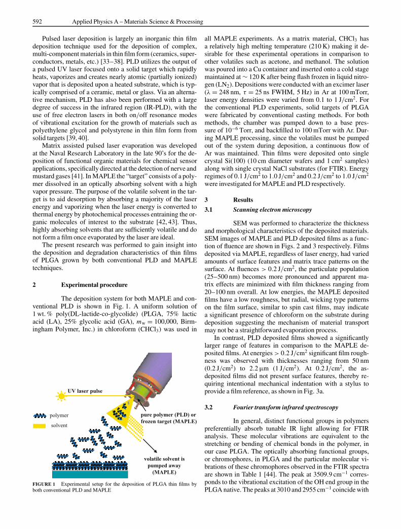
The deposition system for both MAPLE and con-ventional PLD is shown in Fig. 1. A uniform solution of1 wt. % poly(DL-lactide-co-glycolide) (PLGA, 75% lacticacid (LA), 25% glycolic acid (GA), mw = 100,000, Birm-ingham Polymer, Inc.) in chloroform (CHCl3) was used in
FIGURE 1 Experimental setup for the deposition of PLGA thin films byboth conventional PLD and MAPLE
all MAPLE experiments. As a matrix material, CHCl3 hasa relatively high melting temperature (210 K) making it de-sirable for these experimental operations in comparison toother volatiles such as acetone, and methanol. The solutionwas poured into a Cu container and inserted onto a cold stagemaintained at ∼ 120 K after being flash frozen in liquid nitro-gen (LN2). Depositions were conducted with an excimer laser(λ = 248 nm, τ = 25 ns FWHM, 5 Hz) in Ar at 100 mTorr,laser energy densities were varied from 0.1 to 1 J/cm2. Forthe conventional PLD experiments, solid targets of PLGAwere fabricated by conventional casting methods. For bothmethods, the chamber was pumped down to a base pres-sure of 10−6 Torr, and backfilled to 100 mTorr with Ar. Dur-ing MAPLE processing, since the volatiles must be pumpedout of the system during deposition, a continuous flow ofAr was maintained. Thin films were deposited onto singlecrystal Si(100) (10 cm diameter wafers and 1 cm2 samples)along with single crystal NaCl substrates (for FTIR). Energyregimes of 0.1 J/cm2 to 1.0 J/cm2 and 0.2 J/cm2 to 1.0 J/cm2
were investigated for MAPLE and PLD respectively.
3 Results
3.1 Scanning electron microscopy
SEM was performed to characterize the thicknessand morphological characteristics of the deposited materials.SEM images of MAPLE and PLD deposited films as a func-tion of fluence are shown in Figs. 2 and 3 respectively. Filmsdeposited via MAPLE, regardless of laser energy, had variedamounts of surface features and matrix trace patterns on thesurface. At fluences > 0.2 J/cm2, the particulate population(25–500 nm) becomes more pronounced and apparent ma-trix effects are minimized with film thickness ranging from20–100 nm overall. At low energies, the MAPLE depositedfilms have a low roughness, but radial, wicking type patternson the film surface, similar to spin cast films, may indicatea significant presence of chloroform on the substrate duringdeposition suggesting the mechanism of material transportmay not be a straightforward evaporation process.
In contrast, PLD deposited films showed a significantlylarger range of features in comparison to the MAPLE de-posited films. At energies > 0.2 J/cm2 significant film rough-ness was observed with thicknesses ranging from 50 nm(0.2 J/cm2) to 2.2 µm (1 J/cm2). At 0.2 J/cm2, the as-deposited films did not present surface features, thereby re-quiring intentional mechanical indentation with a stylus toprovide a film reference, as shown in Fig. 3a.
3.2 Fourier transform infrared spectroscopy
In general, distinct functional groups in polymerspreferentially absorb tunable IR light allowing for FTIRanalysis. These molecular vibrations are equivalent to thestretching or bending of chemical bonds in the polymer, inour case PLGA. The optically absorbing functional groups,or chromophores, in PLGA and the particular molecular vi-brations of these chromophores observed in the FTIR spectraare shown in Table 1 [44]. The peak at 3509.9 cm−1 corres-ponds to the vibrational excitation of the OH end group in thePLGA native. The peaks at 3010 and 2955 cm−1 coincide with

MERCADO et al. Pulsed laser deposition vs. matrix assisted pulsed laser evaporation for growth of biodegradable polymer thin films 593
FIGURE 2 Scanning electron mi-croscope images of MAPLE depositedthin films of PLGA. The SEM mi-crographs show trends of particulateformation, showing morphology ef-fects in terms of matrix patterns, par-ticle roughness and droplet formationas a function of laser fluence (a–g)while (h, i) illustrating the thicknessregime for the films which rangedfrom 20–100 nm
FIGURE 3 Scanning electron mi-croscope images of PLD depositedthin films of PLGA. The images showincreased surface roughness and un-dulations at energy densities above0.2 J/cm2
Functional Group Corresponding Peak
OH End group 3509.9 cm−1
C–H Stretch of CH3 3010 cm−1 and 2955 cm−1
C–H Stretch of CH2 2885 cm−1
C=O Stretch 1762.6 cm−1
C–O Stretch 1186–1089.6 cm−1
C–H Bends 1450–850 cm−1
TABLE 1 Functional groups for FTIR analysis
the C–H stretches of the CH3 groups. The peak at 2885 cm−1
was indicative of the C–H stretch of CH2 while the peakat 1762.6 cm−1 corresponded to the carbonyl (C=O), vibra-tional excitation. Peaks at 1450 to 800 cm−1 are deemed to bethe traditional “fingerprint” region for this material. The fin-gerprint region is an important identifier for various polymers;Fig. 4 illustrates the complete spectra including the fingerprintregion for native PLGA. Figure 5 shows FTIR spectra fromboth MAPLE (a) and PLD (b) deposited thin films. The re-

594 Applied Physics A – Materials Science & Processing
FIGURE 4 FTIR spectra for native PLGA showing character-istic features at ∼ 3500, 3000, 1750, and 1100 cm−1
FIGURE 5 FTIR spectra for MAPLE (a), and PLD deposited(b), films of PLGA

MERCADO et al. Pulsed laser deposition vs. matrix assisted pulsed laser evaporation for growth of biodegradable polymer thin films 595
sults from the FTIR spectra demonstrate that the depositedfilms resemble the native polymer to a finite degree. Insetsshow a minor peak at 760 cm−1 in both the native and PLD de-posited materials while a minor peak is shown at 780 cm−1 forthe MAPLE deposited materials which could be identified asC–Cl stretch [45].
3.3 Nuclear magnetic resonance
To provide further chemical analysis, NMR wasperformed using proton resonance. The resulting signal peaksdue to the precession of all hydrogen atoms within each func-tional group are shown in Table 2. The multiplet at 5.2 ppmstems from resonance in the CH species in the lactic acidwhile the multiplet at 4.8 ppm corresponds to the resonanceof the CH2 species in the glycolic acid [46]. These peakswere complex multiplets because of the different D-lactide,L-lactide, and glycolic acid monomers that comprise PLGA,and their relationships to each other in the polymer chain. Theoverlapping doublets at 1.55 ppm were attributed to the chi-ral methyl groups in the lactic acid monomer units for bothD- and L- stereographic configurations. The peak at approxi-mately 1.25 ppm is attributed to the methyl group attached tothe hydroxyl end group.
Standard solutions were prepared by dissolving the de-posited films in deuterated chloroform, CDCl3. The NMRspectra from the native PLGA is shown in Fig. 6. Figure 7
Functional Group Corresponding Peak
Lactic acid - CH Multiplet @ 5.2 ppm
Glycolic acid - CH2 Multiplet @ 4.8 ppm
Methyl groups of the D- and Overlapping doubletsL- lactic acid repeat units @ 1.55 ppm
Methyl group attached to the 1.25 ppmhydroxyl endgroup
TABLE 2 Corresponding peaks of functional groups in PLGA measuredby proton resonance
FIGURE 6 Nuclear magnetic resonance spectra from native PLGA show-ing the methyl groups at 1.25 and 1.55 ppm and the glycolic and lactic acidgroups at 4.8 and 5.2 ppm
FIGURE 7 Nuclear magnetic resonance spectra of PLGA deposited byMAPLE (a) and PLD (b)
shows the comparative NMR spectra from the MAPLE (a) andPLD (b) deposited materials. Specifically, the multiplets asso-ciated to the lactide and glycolide groups were similar for bothnative PLGA, MAPLE, and PLD processed films.
3.4 Gel permeation chromatography analysis
GPC analysis of native PLGA in CHCl3 (flowrate = 1 mL/min) is shown in Fig. 8a. The analysis for all ma-terial is shown in Table 3 along with the polydispersity (PD).Molecular weight estimates using a RI detector with linearpolystyrene standards indicates an average molecular weightof 100 kDa for the native polymer. GPC analysis of MAPLEdeposited material is shown in Fig. 8b, the molecular weightwas measured to be ∼ 25 kDa, with a significant shift of theoligomer peak at higher elution volumes to 200 Da. Materials

596 Applied Physics A – Materials Science & Processing
FIGURE 8 GPC elution profiles for native PLGA (a) and MAPLE (b)deposited PLGA showing intermediate (MAPLE 1) and total monomerbreakdown of PLGA (MAPLE 2)
Native PLD MAPLE
mw: 99 kDa Peak 1 Peak 1PD: 1.725 mw: 8.0 kDa mw: 26.0 kDa
PD: 2.7 PD: 2.0
Peak 2 Peak 2mw: 210.0 Da mw: 210.0 Da
PD: 1.0 PD: 1.3
TABLE 3 Molecular weight results from GPC analysis
deposited by PLD (0.38 J/cm2) show contrary behavior withthe oligomer peak remaining at a molecular weight of ∼ 8 kDaand a monomer peak occurring at higher elution volumes at∼ 200 Da as shown in Fig. 9a. It is also noted that below 1 kDathe accuracy of GPC analysis is in question, so it is assumedthat all materials in this region are monomer.
4 Discussion
Growth of PLGA thin films by both methodsshowed trends in both surface morphology and degradationbehavior. In terms of chemistry, the FTIR and the NMR ofthe deposited materials are comparable to the native. A GPC
FIGURE 9 GPC elution profiles for PLD deposited PLGA is shown in (a).The PLD deposited materials showed a large intermediate breakdown peak(PLD1), and a total monomer degradation peak (PLD 2). An overlay of thenative, MAPLE and PLD profiles is shown in (b)
overlay of native and deposited polymers is shown in Fig. 9b.Peaks at long elution volumes (time) are consistent withdegradation of polymer to a lower molecular weight, whichcould be monomer or oligomers. It is clear that both tech-niques significantly reduce the molecular weight of the start-ing material. The data also suggest that MAPLE processedPLGA retained higher molecular weight fractions in compar-ison to PLD, along with a large fraction of monomer, whilePLD processed films showed a broad oligomer peak witha molecular weight of 7 kDa and a smaller monomer fraction.
The overall polymer degradation suggests significant ab-sorption of UV radiation by the polymer in both MAPLE(with the sacrificial matrix) and PLD. The optical absorptionof several functional groups within PLGA can be compared tothat of the functional groups inside the structure of many sol-vents with a known absorption at 248 nm such as acetone [47].By eliminating the low absorption bonds, the carbonyl grouppresent in the PLGA backbone is mainly responsible for thehigh absorption which has also been noted by Gardner be-tween 200 and 300 nm [48]. This absorption of high energyphotons by the carbonyl group was one reason that Bubb et

MERCADO et al. Pulsed laser deposition vs. matrix assisted pulsed laser evaporation for growth of biodegradable polymer thin films 597
FIGURE 10 Digital images of a frozentarget (1 wt. % PLGA-CHCL3) taken (a)prior to ablation, (b) during ablation (twoareas were ablated for comparison), and(c), (d) fractured target following ablationshowing the ablation depth and remainingwall thickness. The target was maintainedin LN2 bath during all measurements
al. were concerned that the carbonyl bonds might break dur-ing laser ablation of PLGA in the PLD case [49]; therefore,a significant deviation in molecular weight from the startingmaterial can be expected.
The deposition characteristics and surface morphology ofthe PLD deposited films are in good agreement with previousresearch [50–54]. In the case of MAPLE deposited materi-als, a high ablation rate of the target combined with an ir-regular surface morphology was observed. Experiments wereperformed (0.237 J/cm2, 5 Hz, 100 mTorr Ar) to determinethe actual ablation rate of the frozen target, followed by frac-ture of the frozen target. By fracturing the frozen targets andimmediately immersing in LN2, cross-section measurementsof the ablation trenches were obtained as shown in Fig. 10.After 6,500 pulses, the ablation trenches were on the order of1.2 cm deep, yielding an ablation rate of ∼ 1.85 µm/pulse,suggesting that a large portion is being vaporized and evapo-rated [55, 56], or that solid spallation [57] of the target surfaceis occurring. This observation may be reflected on the de-posited films shown in Fig. 2b, c where images of the surfacemorphology reflect significant signs of solvent evaporationfrom the films while on the Si substrates. This suggests thateither a large amount of solvent (CHCl3) is transferred to thefilms or that solid layers of the target are landing on the sub-strate, melting, and then in both cases the volatile is pumpedout of the system, leaving behind the wicking patterns on thefilm surfaces.
To further understand the laser-solid interactions that maylead to either large scale evaporation or spallation, optical ab-sorption data is required. Laboratory experiments were con-ducted for both pure solvent and 1 wt. % PLGA solutions dueto a lack of optical absorption data for frozen CHCl3 based so-lutions in the literature. The initial energy distribution in thenear surface regions of the target were calculated based on theBeer–Lambert (BL) law that describes the attenuation of light
with depth:
I(z) = I0e−αz (1)
where I0 is the intensity of the incoming light, I(z) is the in-tensity of the light at a depth of z, and α is the absorptioncoefficient, specific to the material. In general the laser pen-etration depth LP is commonly expressed as 1/α. Transmis-sion data were recorded from pure CHCl3 at film thicknessesof 609 µm, 3048 µm, 5461 µm, and for a 1 wt. % PLGA so-
FIGURE 11 Transmission as a function of film thickness calculated withthe Beer–Lambert relationship. Three transmission measurements at vary-ing thicknesses were recorded for each solution. The upper and lower curveswere generated from targets of pure CHCl3 and CHCl3 w/1 wt. % PLGArespectively

598 Applied Physics A – Materials Science & Processing
lution at 1016 µm, 3149 µm, and 4648 µm. The experimen-tal data was correlated with respect to the BL relationship,with a fit to the data showing an experimental agreement(R2 = 99.5%, pure CHCl3, 99.2% PLGA in solution) fromthe BL relationship. From this initial data, the laser penetra-tion depth, LP, was calculated to be 0.362 cm for pure CHCl3and 0.209 cm for the PLGA solution, indicating a weakly ab-sorbing at 248 nm. The transmission as a function of solutionthickness, z, is shown in Fig. 11.
If the heat capacity is constant, the temperature rise at thestart of ablation can be expressed as
T(z) = T0 +(
αFe−αz
CP
)(2)
where T0 is the initial temperature, CP is the specific heatcapacity, assumed to be independent of temperature, and Fis the fluence. The heat capacity was estimated from tab-ulated data over a temperature range of 221 K to 324 K tobe 117 J/mol-K [58–60], (F = 0.2 J/cm2, � = 1.48 g/cm3,mw = 119.38 g/mol, α = 2.762 cm−1, T0 � 210 K, as thecold stage is maintained at 120 K). From these data set thetemperature rise is calculated to be less than 1 K (at z = 0),which does not support the high ablation rate observed. It isnoted that the value for the heat capacity found does not rep-resent chloroform in the frozen/solid state, which would belower due to the loss of rotational states. For an estimate ofthe change of the Cp for chloroform, the heat capacity of wa-ter varies by approximately 52% from 20 ◦C (75 J/mol-K) to−10 ◦C (36 J/mol-K). For our case with frozen/solid chloro-form, an estimate of the solid is 60 J/mol-K, which still yieldsa negligible temperature rise.
An alternative desorption mechanism that does not re-quire high temperature can be termed “cold laser ablation”or spallation as described by Dingus et al. [57], with furtherinvestigations performed experimentally [61] and computa-tionally [62]. Spallation is a hydrodynamic process in whichlayers next to a free surface are ablated at energy densities toolow for vaporization resulting in large scale material removal.This effect becomes pronounced when τL (laser pulse dura-tion) is shorter than the time of mechanical equilibration orthermal relation of the absorbing volume, τs, usually referredto as stress confinement [63], τL≤τs ∼ Lp/Cs, where Cs is thespeed of sound in the target material, which can be approx-imated as 3000 m/s. For this research, τs is on the order of1200 ns for pure CHCl3, and 696 ns for the PLGA solution,which places the system in the stress confinement regime. Incalculating the stress waves propagating out of the irradiatedvolume, a damping factor can be accounted for [61]
D = 1 − e−θ
θ(3)
where θ = τL/τs = 0.020 for pure solution and 0.035 for the1 wt. % PLGA solution, giving negligible damping values ofD ∼ 0.99 and 0.982 respectively. The amplitude of the peaktensile stress is then given as
σP = D
2Γ
F
LP(4)
where Γ is the Grüneisen coefficient defined as β
�κCpwith
β is the thermal expansion coefficient, κ is the isothermalcompressibility, � is the density, Cp is the specific heatat constant volume. For pure CHCl3 with F = 2000 J/m2,LP = 0.00362 m, D = 0.99, equation (6) predicts a peakstresses, σP, ranging from 276 kPa (for Γ = 1) to 820 kPa (forΓ = 3), which are clearly insufficient to cause spallation asdescribed [61, 62]. Therefore neither temperature nor stresscalculations can account for the experimentally observedablation rate, providing a basis for further research investi-gations of effects that may be related to non-homogenousabsorption.
5 Conclusions
Films grown by PLD were uniform, showinga trend of increased roughness as a function of fluence.MAPLE deposited films did not follow the same trend, withlarge sections of non-uniformity and particulates present atall fluences. Chemical characterization performed with FTIRand NMR did not reveal a significant deviation from the na-tive. Size exclusion analysis with GPC showed a clear shiftto lower molecular weights for both techniques. The GPCprofiles for the MAPLE deposited materials showed a poorlydefined shoulder at 26 kDa, with a large, well defined peak inthe monomer region. The weight distributions for the PLD de-posited materials showed two clearly defined peaks at 7 kDaand in the monomer region, with the peak at 7 kDa dominatingthe trace. Of greater importance to the biomedical commu-nity is the fact that no substantial fraction of toxic species wasobserved in the degraded materials by FTIR or NMR keep-ing the door open for medical application areas with eithertechnique.
The geometric patterns present in the MAPLE films aresolvent evaporation patterns; these patterns are consistentwith solvent evaporation patterns normally associated withthe spin casting process. This may be due to the ejection oflarge slices of the target surface, explosive evaporation, orspallation of layers onto the substrate that melt, leading toevaporation of the solvent, and thus residual polymer was de-posited. A high ablation rate supports this scenario, suggest-ing that large volumes of the target are being ejected, ratherthan entrainment transport of individual molecules. Prelimi-nary calculations for the thermal and stress confinement be-havior based on the Beer-Lambert relationship do not supportthe current spallation or evaporation models, [55–57] furthersuggesting that other mechanisms may dominate the ablationprocess for this system, such as non-linear surface effects,which will be the focus of future research in this area.
ACKNOWLEDGEMENTS This work was supported by the Uni-versity of Virginia and the Air Force Office of Scientific Research under theDURINT program. The authors are thankful to Professors Leonid Zhigileiand Cassandra Fraser for many insightful and helpful discussions.
REFERENCES
1 L.H. Wang, W. Wang, W.G. Zhang, E.T. Kang, W. Huang: Chem. Mater.12, 2212 (2000)
2 A.C. Edrington, A.M. Urbas, P. DeRege, C. Chen, T. Timothy,N. Hadjichristidis, M. Xeridou, L. Fetters, J.D. Joannopoulos, Y. Fink,E.L. Thomas: Adv. Mater. 13, 421 (2001)

MERCADO et al. Pulsed laser deposition vs. matrix assisted pulsed laser evaporation for growth of biodegradable polymer thin films 599
3 Y. Okamoto: Makromol. Chem., Macromol. Symp. 59, 82 (1992)4 C.X. Du, L. Ma, Y. Xu, W.L. Li: J. Appl. Polym. Sci. 66, 1405 (1997)5 A.L. Jenkins, O.M. Uy, G.M. Murray: Anal. Chem. 71, 373 (1999)6 P. Zhang, J.S. Moore: J. Polym. Sci., Part A: Polym. Chem. 38, 207
(2000)7 M.S. Mousa, K. Lorenz, N.S. Xu: Ultramicroscopy 79, 43 (1999)8 R.A. McGill, M.H. Abraham, J.W. Grate: Chemtech 24, 27 (1994)9 B.R. Ringeisen, J. Callahan, P. Wu, A. Pique, B. Spargo, R.A. McGill,
M. Bucaro, H. Kim, D.M. Bubb, D.B. Chrisey: Langmuir 17, 3472(2001)
10 A. Hickey: Respiratory Drug Delivery VI., (Hilton Head, SC: InterpharmPress Inc., 1998)
11 D.A. Edwards, J. Hanes, G. Caponetti, J.S. Hrkach, A. Ben-Jebria,M.L. Eskew, J. Mintzes, D. Deaver, N. Lotan, R. Langer: Science 276,1868 (1997)
12 A. Gopferich, M.J. Alonso, R. Langer: Pharm. Res. 11, 1568 (1994)13 J.D. Talton, J.M. Fitz-Gerald, R.K. Singh, G. Hochhaus: Respiratory
Drug Delivery VII (Hilton Head, SC: Interpharm Press, Inc., 2000)pp. 67–74
14 X. Cui, J.F. Hetke, J.A. Wiler, D.J. Anderson, D.C. Martin: Sens. Actua-tors A 93, 8 (2001)
15 K. Skrobis, D.D. Denton, A. Skrobis: Polymer Engineering and Science30, 193 (1990)
16 M.A. Bopp, G. Tarrach, M.A. Lieb, A.J. Meixner: J. Vac. Sci. Technol.,A 15, 1423 (1997)
17 W.L. Wu, W.E. Wallace: J. Vac. Sci. Technol., B 16, 1958 (1998)18 S. Sakurai, C. Furukawa, A. Okutsu, A. Miyoshi, S. Nomura: Polymer
43, 3359 (2002)19 T.H. Young, Y.H. Huang, L.Y. Chen: J. of Membrane Science 164, 111
(2000)20 See for example, T.A. Skotheim, R.L. Elsenbaumer, J.R. Reynolds (Eds.):
Handbook of Conducting Polymers, 2nd edn., (Dekker, New York 1996)21 A.J. Heeger, S.A. Kivelso, J.R. Schrieffer, W.P. Su: Rev. Mod. Phys. 60,
781 (1998)22 T.M. Lee, S. Mittler-Neher, D. Neher, GI Stegeman, C. Roux, M. Le-
clerc: Opt. Mater. 1, 65 (1992)23 F.F. Shi: Surf. Coat. Technol. 82, 1 (1996)24 P. Favia, R. d’Agostino: Surf. Coat. Technol. 98, 1102 (1998)25 N. Inagaki, S. Tasaka, M. Makino: J. Appl. Polym. Sci. 64, 1031 (1997)26 M.J. Sowa, M.E. Littau, V. Pohray, J.L. Cecchi: J. Vac. Sci. Technol. A
18, 2122 (2000)27 G.H. Hishmeh, T.I. Barr, A. Skylarov, S. Hardcastle: J. Vac. Sci. Tech-
nol. A 14, 1330 (1996)28 K. D’Almeida, J.C. Bernede, F. Ragot, A. Godoy, F.R. Diaz, S. Lefrant:
J. Appl. Poly. Sci. 82, 2042 (2001)29 H. Biederman: J. Vac. Sci. Technol. A 18, 1642 (2000)30 T.R. Gengenbach, H.J. Griesser: J. Polym. Sci. 36, 985 (1998)31 X. Cui, J. Hetke, J.A. Wiler, D.J. Anderson, D.C. Martin: Sens. Actua-
tors A 93, 8 (2001)
32 A. Kiesow, A. Heilmann: Thin Solid Films 343, 338 (1999)33 R.K. Singh, N. Biunno, J. Narayan: Appl. Phys. Lett. 53, 1013 (1988)34 J.T. Cheung, H. Sankur: CRC Critical Reviews in Solid State and Mate-
rials Sciences 15, 63 (1988)35 J.M. Fitz-Gerald, P.D. Rack, T.A. Trottier, M. Ollinger, S.J. Pennycook,
H. Gao, R.K. Singh: J. Appl. Phys. 86, 1759 (1999)36 J.M. Fitz-Gerald, T.A. Trottier, P.H. Holloway, R.K. Singh: Appl. Phys.
Lett. 72, 1838 (1998)37 D.B. Chrisey, J.S. Horwitz: Thin Solid Films 206, 111 (1991)38 D. Lowndes, D.B. Geohegan, A.A. Puretzky, D.P. Norton, C.M. Rou-
leau: Science 273, 898 (1996)39 D.M. Bubb, M.R. Papantonakis, B. Toftmann, J.S. Horwitz, R.A. McGill,
D.B. Chrisey, R.F. Haglund Jr.: J. Appl. Phys. 91, 9809 (2002)40 D.M. Bubb, M.R. Papantonakis, J.S. Horwitz, R.F. Haglund Jr.,
B. Toftmann, R.A. McGill, D.B. Chrisey: Chem. Phys. Lett. 352, 135(2002)
41 R.A. McGill, D.B. Chrisey: Patent, Navy case No. 78, 117 (1999)42 L. Zhigilei, E. Leveugle, B.J. Garrison, Y.G. Yingling, M. Zeifman:
Chem. Rev. 103, 321 (2003)43 K. Dreisewerd: Chem. Rev. 103, 395 (2003)44 Y.P. Li, X.Y. Zhang, Z.H. Gu, Z.H. Zhou, W.F. Yuan, J.J. Zhou, J.H. Zhu,
X.J. Gao: J. Controlled Release 71, 203 (2001)45 D.M. Bubb, P.K. Wu, J.S. Horwitz, J.H. Callahan, M. Galicia, A. Vertes,
R.A. McGill, E.J. Houser, B.R. Ringeisen, D.B. Chrisey: J. Appl. Phys.91, 2055 (2002)
46 J.S. Hrkach, M.T. Peracchia, A. Domb, N. Lotan, R. Langer: Biomateri-als 18, 27 (1997)
47 S.L. Murov: Handbook of Photochemistry (Marcel Dekker, Inc., 1973)48 W. Schnabel: Polymer Degradation: Principles and Practical Applica-
tions (Hanser, 1982)49 D.M. Bubb, B. Toftmann, R.F. Haglund Jr., J.S. Horwitz, M.R. Papan-
tonakis, R.A. McGill, P.K. Wu, D.B. Chrisey: Appl. Phys. A 74, 123(2002)
50 R. Srinivasan, B. Braren: Chem. Rev. 89, 1303 (1989)51 R. Srinivasan, B. Braren, R.W. Dreyfus: J. Appl. Phys. 61, 372 (1986)52 G.M. Davis, M.C. Gower: J. Appl. Phys. 61, 2090 (1987)53 G.B. Blanchet, S.I. Shah: Appl. Phys. Lett. 62, 1026 (1993)54 P.E. Dyer, D.M. Karnakis: Appl. Phys. Lett. 64, 1344 (1993)55 L.V. Zhigilei, B.J. Garrison: J. Appl. Phys. 88, 1281 (2000)56 T.E. Itina, L.V. Zhigilei, B.J. Garrison: Nucl. Instrum. Methods Phys.
Res., Sect. B 180, 238 (2001)57 R.S. Dingus, R.J. Scammom: SPIE Proc. 1427, 45 (1991)58 V.Y. Kurbatov: Zh. Obshch. Kim. 18, 372 (1948)59 W.T. Richards, J.H. Wallace Jr.: J. Am. Chem. Soc. 54, 2705 (1932)60 J.W. Willams, F. Daniels: J. Am. Chem. Soc. 46, 903 (1924)61 R. Cramer, R.F. Haglund Jr., F. Hillenkamp: J. Mass Spectrom. Ion Pro-
cesses 169/170, 51 (1997)62 E. Leveugle, D. Ivanov, L.V. Zhigilei: Appl. Phys. A 79, 1643 (2004)63 L.V. Zhigilei, B.J. Garrison: Appl. Phys. A 69[Suppl.], 75 (1999)

![PbTe thin films grown by femtosecond pulsed laser deposition. · electrodeposition [5], molecular beam epitaxy [6] and pulsed laser deposition [7,8,9 ] More recently, PbTe grown in](https://static.fdocuments.net/doc/165x107/5c0d44a109d3f247038d61bf/pbte-thin-films-grown-by-femtosecond-pulsed-laser-electrodeposition-5-molecular.jpg)


![Pulsed Laser Deposition of YSZ and Al2O3 Thin Films: Part 1 ......thin films [16-26]. Pulsed laser deposition has also been used for the development of nano-structured thin films [27,](https://static.fdocuments.net/doc/165x107/60f688b3c8026a3be761a2f6/pulsed-laser-deposition-of-ysz-and-al2o3-thin-films-part-1-thin-films-16-26.jpg)