AJA MAGNETRON SPUTTER SYSTEM OPERATING MANUAL … Built... · HOMEBUILT RF & DC SPUTTER SYSTEM...
20
HOMEBUILT RF & DC SPUTTER SYSTEM OPERATING MANUAL Version: 4.0 Oct 2014 UNIVERSITY OF TEXAS AT ARLINGTON Nanotechnology Research Center
Transcript of AJA MAGNETRON SPUTTER SYSTEM OPERATING MANUAL … Built... · HOMEBUILT RF & DC SPUTTER SYSTEM...
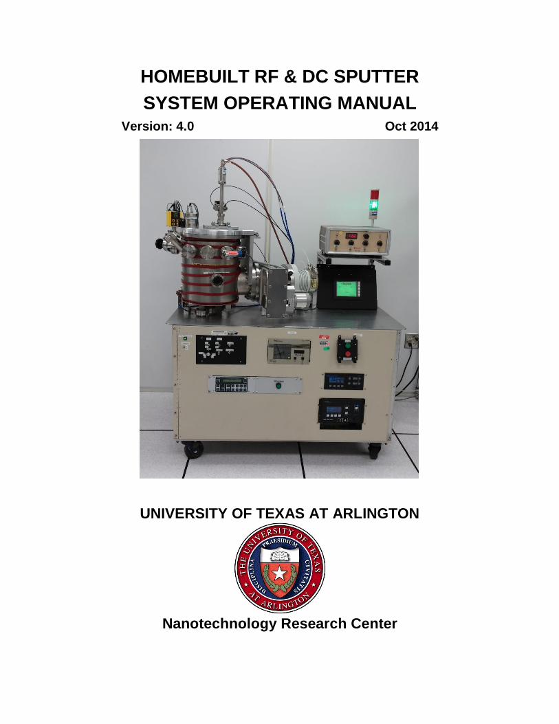
HOMEBUILT RF & DC SPUTTER
SYSTEM OPERATING MANUAL Version: 4.0 Oct 2014
UNIVERSITY OF TEXAS AT ARLINGTON
Nanotechnology Research Center
DOCUMENT: HOMEBUILT RF & DC SPUTTER STANDARD OPERATING PROCEDURE Version: 4.0
2
TABLE OF CONTENTS
1. Introduction………………………………………………………..3
1.1 Scope………...…………………………….…………......3
1.2 Description…………………………………………..……3
1.3 Safety……………………………………………....……..3
2. Hardware ..............................……………………..……………....4
3. Requirements……………………………………..….….………..4
3.1 Training……………………………………..……..…..….4
3.2 Restrictions………………………………….……….…...4
4 System Operating Procedures………………………………....5
4.1 Venting the process chamber ……….;………….….….7
4.2 Installing the Target and Loading a Sample….……...14
4.3 Venting the System for Sample Removal……..….….19
4.4 Troubleshooting Faults and Interlocks……………..…21
5 TABLE1: Material Deposition Rates……….……..…….…….29
DOCUMENT: HOMEBUILT RF & DC SPUTTER STANDARD OPERATING PROCEDURE Version: 4.0
3
1.0 INTRODUCTION
1.1 Scope These procedures apply to the Homebuilt RF & DC sputter system. All
maintenance should follow the procedures set forth in the manufacturer’s maintenance and operations manuals. This document is for reference only. Personnel should be trained by authorized staff before operating this equipment.
1.2 Description Homebuilt RF & DC Sputtering System (Homebuilt) can be used to
sputter highly uniform metal, semiconductor or dielectric films. The Homebuilt sputter is a fully automated PLC controlled deposition system. All vacuum functionality and RF to DC switching is controlled by a programmable logic controller (PLC) from the system touchscreen. The system features top-down sputtering so no clips or sample retention mechanism is required. Substrates up to 4” in diameter are accommodated on the rotating sample table.
1.3 Safety
1.3.1 This machine is connected to HIGH VOLTAGE. Be very careful and aware of electrical hazards. If you encounter any electrical malfunctions contact a NanoFAB staff member immediately.
1.3.2 This machine uses DC & RF power. DO NOT operate this machine with any cables disconnected or any component enclosures/panels open.
1.3.3 Although this system has no heated substrate carrier, the system can heat the sample carrier plate to high temperatures from sputtering during extended high power depositions. Be careful of high temperatures when removing the sample carrier plate from the system.
1.3.4 This machine has both water flow and vacuum interlocks to prevent damage to the system and RF potential from being present when the system is at atmosphere. For safety users should however power the RF and DC generators OFF while changing/removing targets. If you encounter any water flow malfunctions or if the RF generator will not come ON notify NanoFab staff immediately.
1.3.5 This machine offers Ar, N2, & O2 gases for processing. The process gases are normally pumped out of the system. If the process pressure is not being maintained or system cannot reach base pressure notify NanoFAB staff immediately.
DOCUMENT: HOMEBUILT RF & DC SPUTTER STANDARD OPERATING PROCEDURE Version: 4.0
4
2.0 HARDWARE
2.1. 3” magnetron gun, accepts 3” X .250” or 3” X .125”
dielectric or non-magnetic metal targets
2.2. 300 Watt Seren RF sputtering supply
2.3. 500 Watt MDX DC sputtering supply
2.4. N2, Ar, & O2 Process gases all using 50 SCCM MFC’s
2.5. Substrates up to 4” diameter allowed
2.6. PLC automation with vacuum and recipe control
2.7. 6 – 20 RPM Rotating sample carrier
3.0 REQUIREMENTS
3.1 Training You must be a qualified user on the Homebuilt Sputtering System.
3.2 Restrictions
3.2.1 Only authorized users that have been trained by NanoFab staff are permitted to use this system. Authorized users must obtain a reservation through NanoFab’ s online system before operating.
3.2.2 Assure that no one is using the system by checking the log book. An incomplete entry in the log book indicates that the system may be in use.
3.2.3 Verify no wafers/samples are present and examine if the Light tower green lamp is flashing or on steady. If the light tower green lamp is illuminated then the system is in use.
3.2.4 All system runs must be entered in the system logbook.
DOCUMENT: HOMEBUILT RF & DC SPUTTER STANDARD OPERATING PROCEDURE Version: 4.0
5
4.0 System Operating Procedure
4.1 Venting the process chamber
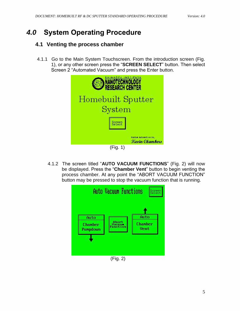
4.1.1 Go to the Main System Touchscreen. From the introduction screen (Fig. 1), or any other screen press the “SCREEN SELECT” button. Then select Screen 2 “Automated Vacuum” and press the Enter button.
(Fig. 1)
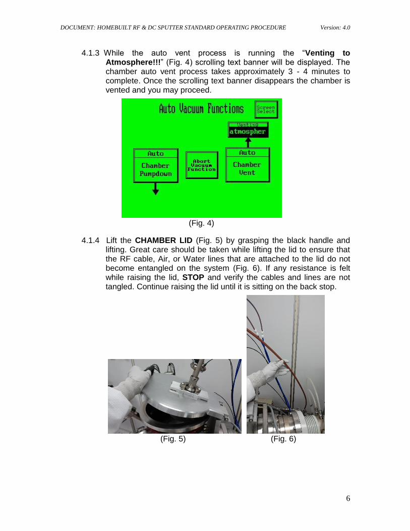
4.1.2 The screen titled “AUTO VACUUM FUNCTIONS” (Fig. 2) will now be displayed. Press the “Chamber Vent” button to begin venting the process chamber. At any point the “ABORT VACUUM FUNCTION” button may be pressed to stop the vacuum function that is running.
(Fig. 2)
DOCUMENT: HOMEBUILT RF & DC SPUTTER STANDARD OPERATING PROCEDURE Version: 4.0
6
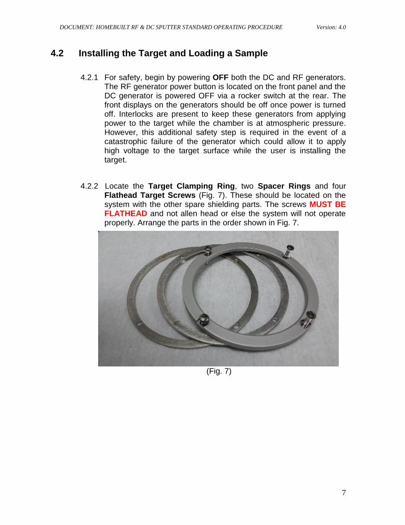
4.1.3 While the auto vent process is running the “Venting to Atmosphere!!!” (Fig. 4) scrolling text banner will be displayed. The chamber auto vent process takes approximately 3 - 4 minutes to complete. Once the scrolling text banner disappears the chamber is vented and you may proceed.
(Fig. 4)
4.1.4 Lift the CHAMBER LID (Fig. 5) by grasping the black handle and lifting. Great care should be taken while lifting the lid to ensure that the RF cable, Air, or Water lines that are attached to the lid do not become entangled on the system (Fig. 6). If any resistance is felt while raising the lid, STOP and verify the cables and lines are not tangled. Continue raising the lid until it is sitting on the back stop.
(Fig. 5) (Fig. 6)
DOCUMENT: HOMEBUILT RF & DC SPUTTER STANDARD OPERATING PROCEDURE Version: 4.0
7
4.2 Installing the Target and Loading a Sample
4.2.1 For safety, begin by powering OFF both the DC and RF generators. The RF generator power button is located on the front panel and the DC generator is powered OFF via a rocker switch at the rear. The front displays on the generators should be off once power is turned off. Interlocks are present to keep these generators from applying power to the target while the chamber is at atmospheric pressure. However, this additional safety step is required in the event of a catastrophic failure of the generator which could allow it to apply high voltage to the target surface while the user is installing the target.
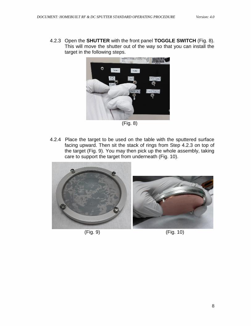
4.2.2 Locate the Target Clamping Ring, two Spacer Rings and four Flathead Target Screws (Fig. 7). These should be located on the system with the other spare shielding parts. The screws MUST BE FLATHEAD and not allen head or else the system will not operate properly. Arrange the parts in the order shown in Fig. 7.
(Fig. 7)
DOCUMENT: HOMEBUILT RF & DC SPUTTER STANDARD OPERATING PROCEDURE Version: 4.0
8
4.2.3 Open the SHUTTER with the front panel TOGGLE SWITCH (Fig. 8). This will move the shutter out of the way so that you can install the target in the following steps.
(Fig. 8)
4.2.4 Place the target to be used on the table with the sputtered surface facing upward. Then sit the stack of rings from Step 4.2.3 on top of the target (Fig. 9). You may then pick up the whole assembly, taking care to support the target from underneath (Fig. 10).
(Fig. 9) (Fig. 10)
DOCUMENT: HOMEBUILT RF & DC SPUTTER STANDARD OPERATING PROCEDURE Version: 4.0
9
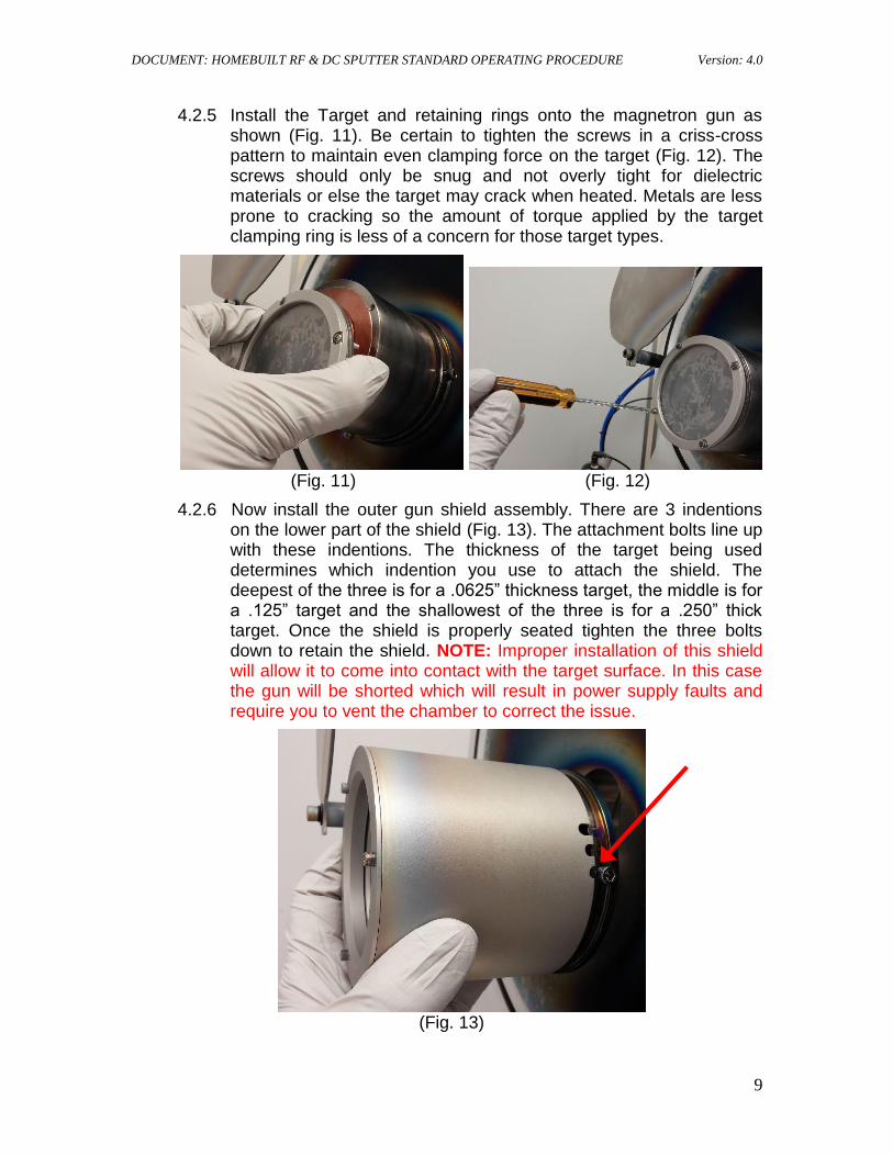
4.2.5 Install the Target and retaining rings onto the magnetron gun as shown (Fig. 11). Be certain to tighten the screws in a criss-cross pattern to maintain even clamping force on the target (Fig. 12). The screws should only be snug and not overly tight for dielectric materials or else the target may crack when heated. Metals are less prone to cracking so the amount of torque applied by the target clamping ring is less of a concern for those target types.
(Fig. 11) (Fig. 12)
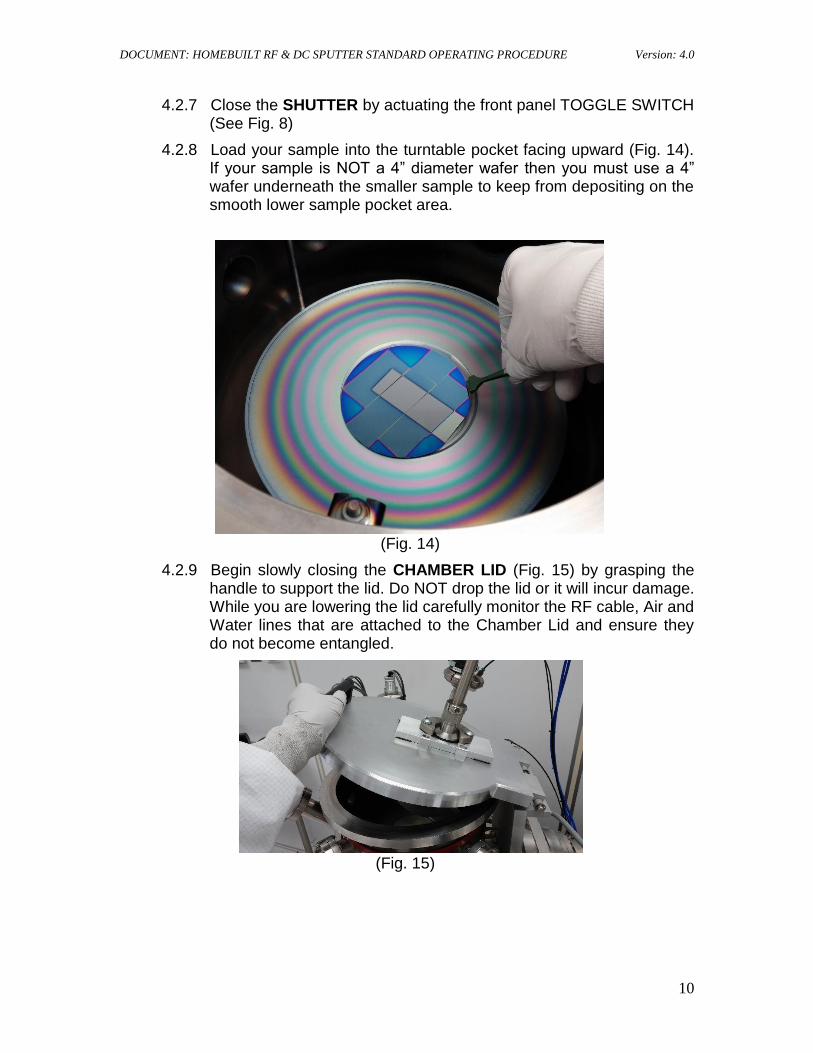
4.2.6 Now install the outer gun shield assembly. There are 3 indentions on the lower part of the shield (Fig. 13). The attachment bolts line up with these indentions. The thickness of the target being used determines which indention you use to attach the shield. The deepest of the three is for a .0625” thickness target, the middle is for a .125” target and the shallowest of the three is for a .250” thick target. Once the shield is properly seated tighten the three bolts down to retain the shield. NOTE: Improper installation of this shield will allow it to come into contact with the target surface. In this case the gun will be shorted which will result in power supply faults and require you to vent the chamber to correct the issue.
(Fig. 13)
DOCUMENT: HOMEBUILT RF & DC SPUTTER STANDARD OPERATING PROCEDURE Version: 4.0
10
4.2.7 Close the SHUTTER by actuating the front panel TOGGLE SWITCH (See Fig. 8)
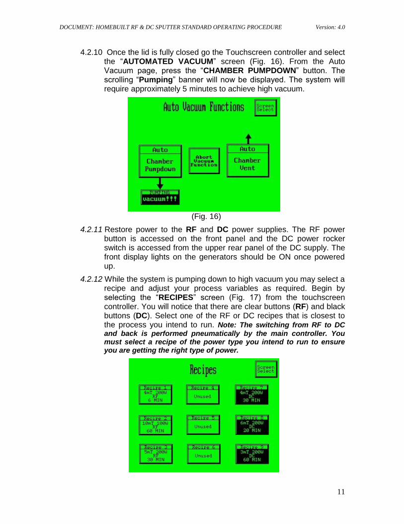
4.2.8 Load your sample into the turntable pocket facing upward (Fig. 14). If your sample is NOT a 4” diameter wafer then you must use a 4” wafer underneath the smaller sample to keep from depositing on the smooth lower sample pocket area.
(Fig. 14)
4.2.9 Begin slowly closing the CHAMBER LID (Fig. 15) by grasping the handle to support the lid. Do NOT drop the lid or it will incur damage. While you are lowering the lid carefully monitor the RF cable, Air and Water lines that are attached to the Chamber Lid and ensure they do not become entangled.
(Fig. 15)
DOCUMENT: HOMEBUILT RF & DC SPUTTER STANDARD OPERATING PROCEDURE Version: 4.0
11
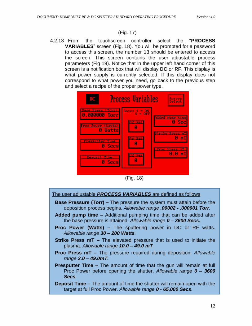
4.2.10 Once the lid is fully closed go the Touchscreen controller and select the “AUTOMATED VACUUM” screen (Fig. 16). From the Auto Vacuum page, press the “CHAMBER PUMPDOWN” button. The scrolling “Pumping” banner will now be displayed. The system will require approximately 5 minutes to achieve high vacuum.
(Fig. 16)
4.2.11 Restore power to the RF and DC power supplies. The RF power button is accessed on the front panel and the DC power rocker switch is accessed from the upper rear panel of the DC supply. The front display lights on the generators should be ON once powered up.
4.2.12 While the system is pumping down to high vacuum you may select a recipe and adjust your process variables as required. Begin by selecting the “RECIPES” screen (Fig. 17) from the touchscreen controller. You will notice that there are clear buttons (RF) and black buttons (DC). Select one of the RF or DC recipes that is closest to the process you intend to run. Note: The switching from RF to DC
and back is performed pneumatically by the main controller. You must select a recipe of the power type you intend to run to ensure you are getting the right type of power.
DOCUMENT: HOMEBUILT RF & DC SPUTTER STANDARD OPERATING PROCEDURE Version: 4.0
12
(Fig. 17)
4.2.13 From the touchscreen controller select the “PROCESS VARIABLES” screen (Fig. 18). You will be prompted for a password to access this screen, the number 13 should be entered to access the screen. This screen contains the user adjustable process parameters (Fig 19). Notice that in the upper left hand corner of this screen is a notification box that will display DC or RF. This display is what power supply is currently selected. If this display does not correspond to what power you need, go back to the previous step and select a recipe of the proper power type.
(Fig. 18)
The user adjustable PROCESS VARIABLES are defined as follows
Base Pressure (Torr) – The pressure the system must attain before the deposition process begins. Allowable range .00002 - .000001 Torr.
Added pump time – Additional pumping time that can be added after the base pressure is attained. Allowable range 0 – 3600 Secs.
Proc Power (Watts) – The sputtering power in DC or RF watts. Allowable range 30 – 200 Watts.
Strike Press mT – The elevated pressure that is used to initiate the plasma. Allowable range 10.0 – 49.0 mT.
Proc Press mT – The pressure required during deposition. Allowable range 2.0 – 49.0mT.
Presputter Time – The amount of time that the gun will remain at full Proc Power before opening the shutter. Allowable range 0 – 3600 Secs.
Deposit Time – The amount of time the shutter will remain open with the target at full Proc Power. Allowable range 0 - 65,000 Secs.
DOCUMENT: HOMEBUILT RF & DC SPUTTER STANDARD OPERATING PROCEDURE Version: 4.0
13
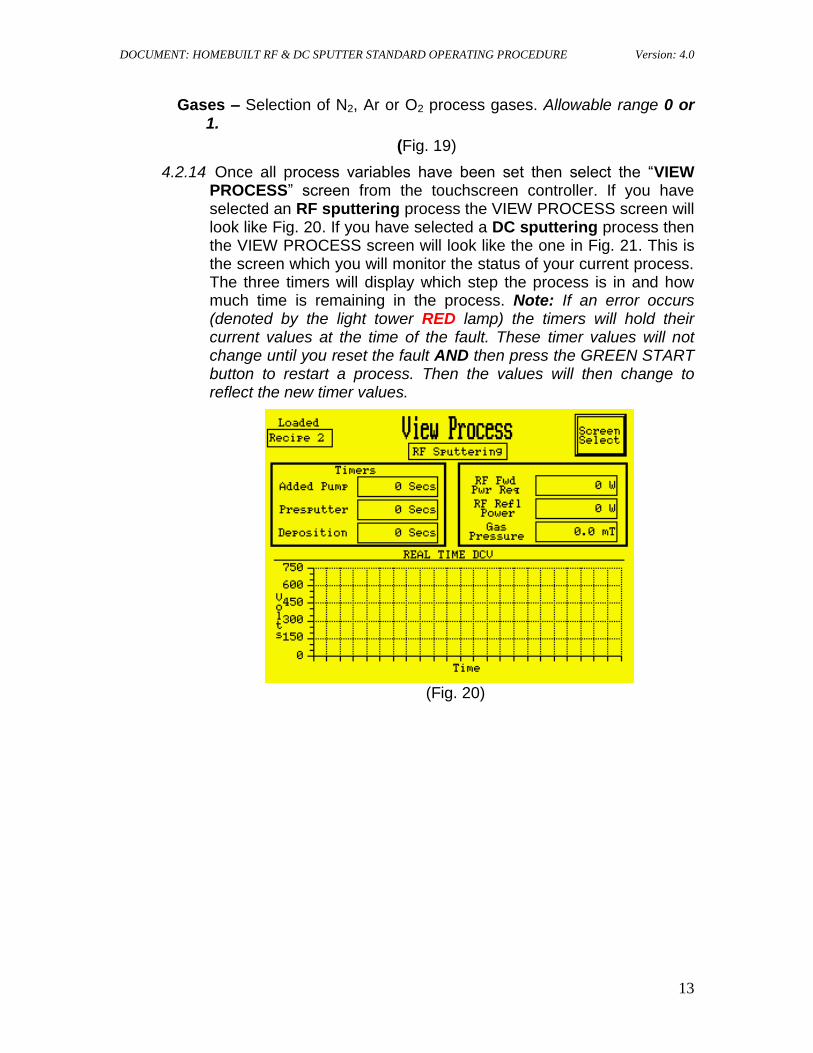
Gases – Selection of N2, Ar or O2 process gases. Allowable range 0 or 1.
(Fig. 19)
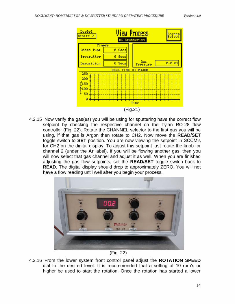
4.2.14 Once all process variables have been set then select the “VIEW PROCESS” screen from the touchscreen controller. If you have selected an RF sputtering process the VIEW PROCESS screen will look like Fig. 20. If you have selected a DC sputtering process then the VIEW PROCESS screen will look like the one in Fig. 21. This is the screen which you will monitor the status of your current process. The three timers will display which step the process is in and how much time is remaining in the process. Note: If an error occurs (denoted by the light tower RED lamp) the timers will hold their current values at the time of the fault. These timer values will not change until you reset the fault AND then press the GREEN START button to restart a process. Then the values will then change to reflect the new timer values.
(Fig. 20)
DOCUMENT: HOMEBUILT RF & DC SPUTTER STANDARD OPERATING PROCEDURE Version: 4.0
14
(Fig.21)
4.2.15 Now verify the gas(es) you will be using for sputtering have the correct flow setpoint by checking the respective channel on the Tylan RO-28 flow controller (Fig. 22). Rotate the CHANNEL selector to the first gas you will be using, if that gas is Argon then rotate to CH2. Now move the READ/SET toggle switch to SET position. You are now viewing the setpoint in SCCM’s for CH2 on the digital display. To adjust this setpoint just rotate the knob for channel 2 (under the Ar label). If you will be flowing another gas, then you will now select that gas channel and adjust it as well. When you are finished adjusting the gas flow setpoints, set the READ/SET toggle switch back to READ. The digital display should drop to approximately ZERO. You will not have a flow reading until well after you begin your process.
(Fig. 22)
4.2.16 From the lower system front control panel adjust the ROTATION SPEED dial to the desired level. It is recommended that a setting of 10 rpm’s or higher be used to start the rotation. Once the rotation has started a lower
DOCUMENT: HOMEBUILT RF & DC SPUTTER STANDARD OPERATING PROCEDURE Version: 4.0
15
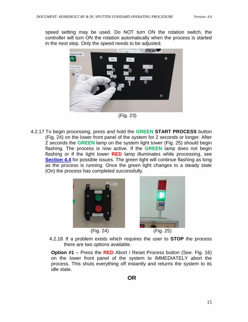
speed setting may be used. Do NOT turn ON the rotation switch, the controller will turn ON the rotation automatically when the process is started in the next step. Only the speed needs to be adjusted.
(Fig. 23)
4.2.17 To begin processing, press and hold the GREEN START PROCESS button (Fig. 24) on the lower front panel of the system for 2 seconds or longer. After 2 seconds the GREEN lamp on the system light tower (Fig. 25) should begin flashing. The process is now active. If the GREEN lamp does not begin flashing or if the light tower RED lamp illuminates while processing, see Section 4.4 for possible issues. The green light will continue flashing as long as the process is running. Once the green light changes to a steady state (On) the process has completed successfully.
(Fig. 24) (Fig. 25)
4.2.18 If a problem exists which requires the user to STOP the process there are two options available.
Option #1 – Press the RED Abort / Reset Process button (See. Fig. 16) on the lower front panel of the system to IMMEDIATELY abort the process. This shuts everything off instantly and returns the system to its idle state.
OR
DOCUMENT: HOMEBUILT RF & DC SPUTTER STANDARD OPERATING PROCEDURE Version: 4.0
16
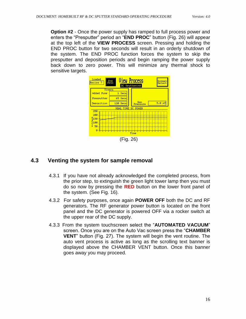
Option #2 - Once the power supply has ramped to full process power and enters the “Presputter” period an “END PROC” button (Fig. 26) will appear at the top left of the VIEW PROCESS screen. Pressing and holding the END PROC button for two seconds will result in an orderly shutdown of the system. The END PROC function forces the system to skip the presputter and deposition periods and begin ramping the power supply back down to zero power. This will minimize any thermal shock to sensitive targets.
(Fig. 26)
4.3 Venting the system for sample removal
4.3.1 If you have not already acknowledged the completed process, from the prior step, to extinguish the green light tower lamp then you must do so now by pressing the RED button on the lower front panel of the system. (See Fig. 16).
4.3.2 For safety purposes, once again POWER OFF both the DC and RF generators. The RF generator power button is located on the front panel and the DC generator is powered OFF via a rocker switch at the upper rear of the DC supply.
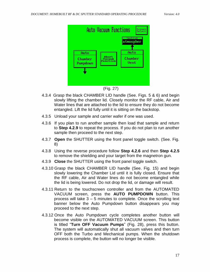
4.3.3 From the system touchscreen select the “AUTOMATED VACUUM” screen. Once you are on the Auto Vac screen press the “CHAMBER VENT” button (Fig. 27). The system will begin the vent routine. The auto vent process is active as long as the scrolling text banner is displayed above the CHAMBER VENT button. Once this banner goes away you may proceed.
DOCUMENT: HOMEBUILT RF & DC SPUTTER STANDARD OPERATING PROCEDURE Version: 4.0
17
(Fig. 27)
4.3.4 Grasp the black CHAMBER LID handle (See. Figs. 5 & 6) and begin slowly lifting the chamber lid. Closely monitor the RF cable, Air and Water lines that are attached to the lid to ensure they do not become entangled. Lift the lid fully until it is sitting on the backstop.
4.3.5 Unload your sample and carrier wafer if one was used.
4.3.6 If you plan to run another sample then load that sample and return to Step 4.2.9 to repeat the process. If you do not plan to run another sample then proceed to the next step.
4.3.7 Open the SHUTTER using the front panel toggle switch. (See. Fig. 8)
4.3.8 Using the reverse procedure follow Step 4.2.6 and then Step 4.2.5 to remove the shielding and your target from the magnetron gun.
4.3.9 Close the SHUTTER using the front panel toggle switch.
4.3.10 Grasp the black CHAMBER LID handle (See. Fig. 15) and begin slowly lowering the Chamber Lid until it is fully closed. Ensure that the RF cable, Air and Water lines do not become entangled while the lid is being lowered. Do not drop the lid, or damage will result.
4.3.11 Return to the touchscreen controller and from the AUTOMATED VACUUM screen, press the AUTO PUMPDOWN button. This process will take 3 – 5 minutes to complete. Once the scrolling text banner below the Auto Pumpdown button disappears you may proceed to the next step.
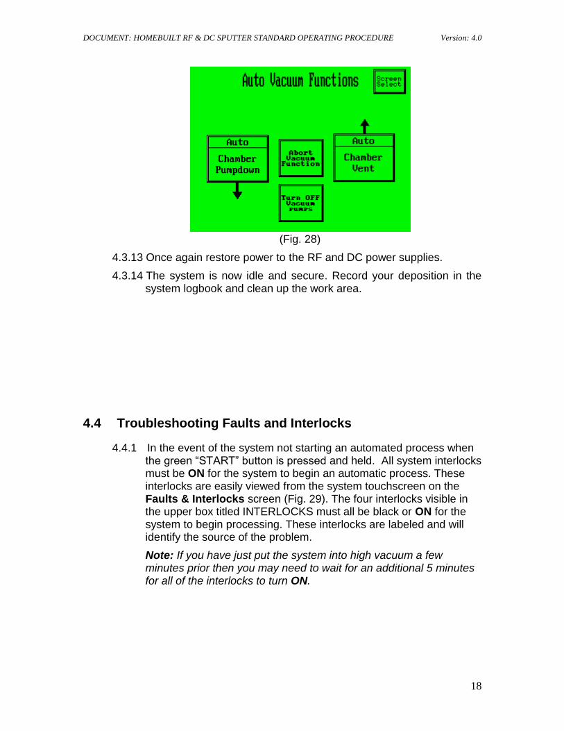
4.3.12 Once the Auto Pumpdown cycle completes another button will become visible on the AUTOMATED VACUUM screen. This button is titled “Turn OFF Vacuum Pumps” (Fig. 28), press this button. The system will automatically shut all vacuum valves and then turn OFF both the Turbo and Mechanical pumps. When the shutdown process is complete, the button will no longer be visible.
DOCUMENT: HOMEBUILT RF & DC SPUTTER STANDARD OPERATING PROCEDURE Version: 4.0
18
(Fig. 28)
4.3.13 Once again restore power to the RF and DC power supplies.
4.3.14 The system is now idle and secure. Record your deposition in the system logbook and clean up the work area.
4.4 Troubleshooting Faults and Interlocks
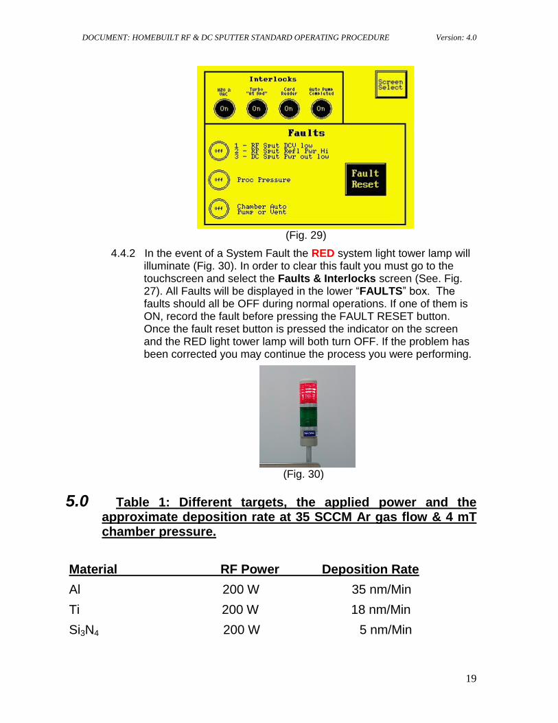
4.4.1 In the event of the system not starting an automated process when the green “START” button is pressed and held. All system interlocks must be ON for the system to begin an automatic process. These interlocks are easily viewed from the system touchscreen on the Faults & Interlocks screen (Fig. 29). The four interlocks visible in the upper box titled INTERLOCKS must all be black or ON for the system to begin processing. These interlocks are labeled and will identify the source of the problem.
Note: If you have just put the system into high vacuum a few minutes prior then you may need to wait for an additional 5 minutes for all of the interlocks to turn ON.
DOCUMENT: HOMEBUILT RF & DC SPUTTER STANDARD OPERATING PROCEDURE Version: 4.0
19
(Fig. 29)
4.4.2 In the event of a System Fault the RED system light tower lamp will illuminate (Fig. 30). In order to clear this fault you must go to the touchscreen and select the Faults & Interlocks screen (See. Fig. 27). All Faults will be displayed in the lower “FAULTS” box. The faults should all be OFF during normal operations. If one of them is ON, record the fault before pressing the FAULT RESET button. Once the fault reset button is pressed the indicator on the screen and the RED light tower lamp will both turn OFF. If the problem has been corrected you may continue the process you were performing.
(Fig. 30)
5.0 Table 1: Different targets, the applied power and the approximate deposition rate at 35 SCCM Ar gas flow & 4 mT chamber pressure.
Material RF Power Deposition Rate
Al 200 W 35 nm/Min
Ti 200 W 18 nm/Min
Si3N4 200 W 5 nm/Min
DOCUMENT: HOMEBUILT RF & DC SPUTTER STANDARD OPERATING PROCEDURE Version: 4.0
20
Material DC Power Deposition Rate
Al 200 W 58 nm/Min
Ti 200 W 35 nm/Min