AJA MAGNETRON SPUTTER SYSTEM OPERATING … Sputter.pdfdocument: aja sputter standard operating...
52
DOCUMENT: AJA SPUTTER STANDARD OPERATING PROCEDURE Version: 1.0 AJA MAGNETRON SPUTTER SYSTEM OPERATING MANUAL Version: 1.0 Oct 2009 UNIVERSITY OF TEXAS AT ARLINGTON Nanofabrication Research and Teaching Facility
Transcript of AJA MAGNETRON SPUTTER SYSTEM OPERATING … Sputter.pdfdocument: aja sputter standard operating...
DOCUMENT: AJA SPUTTER STANDARD OPERATING PROCEDURE Version: 1.0
AJA MAGNETRON SPUTTER SYSTEM OPERATING MANUAL
Version: 1.0 Oct 2009
UNIVERSITY OF TEXAS AT ARLINGTON
Nanofabrication Research and Teaching
Facility
DOCUMENT: AJA SPUTTER STANDARD OPERATING PROCEDURE Version: 1.0
2
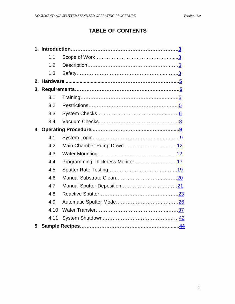
TABLE OF CONTENTS
1. Introduction………………………………………………………..3 1.1 Scope of Work………………………………………......3 1.2 Description………………………………………….……3 1.3 Safety……………………………………………...……..3
2. Hardware ..............................…………………………….……....5 3. Requirements……………………………………..….….….……..5
3.1 Training…………………………………….……..…..….5 3.2 Restrictions………………………………………….…...5 3.3 System Checks…………………………….……....……6 3.4 Vacuum Checks……………………………...…….……8
4 Operating Procedure..………………………..…..……..…….....9 4.1 System Login…………………………….…....…...….…9 4.2 Main Chamber Pump Down………………….…..…...12 4.3 Wafer Mounting……………………………….……..…12 4.4 Programming Thickness Monitor……………………..17 4.5 Sputter Rate Testing…………………………….……..19 4.6 Manual Substrate Clean……………………….………20 4.7 Manual Sputter Deposition……………………….……21 4.8 Reactive Sputter………………………………….……..23 4.9 Automatic Sputter Mode……………………….….……26 4.10 Wafer Transfer……………………………………..……37 4.11 System Shutdown………………………………….……42
5 Sample Recipes…….………………………..…..….……..…......44
DOCUMENT: AJA SPUTTER STANDARD OPERATING PROCEDURE Version: 1.0
3
1 INTRODUCTION
1.1 Scope These procedures apply to the AJA International UHV Magnetron Sputtering system. All maintenance should follow the procedures set forth in the manufacturer’s maintenance and operations manuals. This document is for reference only. Personnel should be trained by authorized staff before operating this equipment.
1.2 Description The AJA International UHV Sputtering System uses five shuttered magnetron guns containing two inch diameter targets to sputter deposit single thin films or stacked film layers on 1”- 4” diameter wafers, glass slides and small samples with optional substrate heating and rotation for enhanced film properties and improved film uniformity. This tool is equipped with one DC gun for the deposition of conductive material ( Al ) and four RF guns for the deposition of semi- conductive or non-conductive materials ( Si, SiO2, Al2O3, Si3N4 ,Cr2O3,ITO ,YBCO and other approved materials). This tool also has RF substrate biasing with controlled Ar, N2, O2 gas flow for plasma substrate cleaning or ion assisted reactive sputter deposition.
1.3 Safety 1.3.1 This machine is connected to HIGH VOLTAGE. Be very careful and aware of
electrical hazards. If you encounter any electrical malfunctions, contact NanoFAB staff immediately
1.3.2 This machine uses DC and RF frequency power. DO NOT operate this machine with any DC or RF cables disconnected or any component enclosures/panels open.
1.3.3 This machine can heat substrates to high temperatures (850C). Make sure you wait until the substrate temperature is < 50 C before transferring your sample to the load lock chamber.
1.3.4 This machine has only water flow interlocks to prevent over heating the substrate heater, RF generators, turbo pumps and quartz crystal. If you encounter any water flow malfunctions or the water flow interlock light comes ON notify NanoFAB staff immediately.
1.3.5 This machine has an EMO (Emergency Off) switch/button mounted on the top panel. The EMO switch should be pressed only in an emergency. An emergency would be fire, smoke, electrocution hazards, and an injury to anyone using this particular piece of equipment. If the EMO is pressed notify NanoFAB staff immediately.
1.3.6 This machine uses Ar, N2, and O2 gas which in high concentrations can be asphyxiates. The process gases are normally pumped out of the system. If the process pressure is not being maintained or system cannot reach base pressure notify NanoFAB staff immediately.
1.3.7 Read any posted NanoFAB Engineering Change Notices (ECN) for any hardware, process or safety changes before running the tool.
DOCUMENT: AJA SPUTTER STANDARD OPERATING PROCEDURE Version: 1.0
4
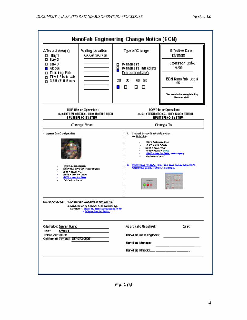
Fig: 1 (a)
DOCUMENT: AJA SPUTTER STANDARD OPERATING PROCEDURE Version: 1.0
5
2 HARDWARE
2.1 Process Gases: Ar, N2, O2
2.2 DC – Magnetron: 500 watts maximum
2.3 RF – Magnetron: 300 watts maximum
2.4 Substrate temperature: 25 C to 850 C
3 REQUIREMENTS
3.1 Training You must be a qualified user on the AJA International HV Sputtering System. The sputter system can be used to deposit Si, SiO2, Si3N4, YBCO, ITO, Al2O3 and other approved
3.2 Restrictions
materials on 1”- 4” diameter wafers, glass slides, and small samples by using the substrate holder clips. Extremely small pieces can be processed by using longer holder clips or bonding to larger carrier wafer (bond with drop silver paint, vacuum tape, and drop of baked photo resist, MUNG II paste or other approved bonding material)
3.2.1 When sputtering any material the wafer holder MUST be mounted to the rotator spindle to prevent coating the heating lamp window.
3.2.2 If sputtering in manual mode, the plasma parameters (RF forward and reflected power, gas flows, sputter pressure, etc.) should be monitored every 30 minutes. If any parameters are > ± 5% of set points or reflected power is > ± 5% of forward power set point contact NanoFAB staff immediately.
3.2.3 The maximum RF power to any RF Gun is 150 Watts during process. The minimum RF or DC power ramping is 100 Watts/min.
3.2.4 The maximum sputter time is 5 hours. If more sputter time is needed then stop your process and keep system idle (chamber under high vacuum) for 1 hour, then resume process.
3.2.5 No substrate heating allowed if using bonding material. 3.2.6 When using the substrate heater be careful not to over heat the wafer/samples to
prevent any wafer breakage, metal or any other material to flow. 3.2.7 IF you are using the substrate heater the Mounting Plate Rotational controller
must be ON to avoid damaging the substrate holder. 3.2.8 If you are using the substrate heater make sure you wait until the substrate
temperature is < 50C° before transferring your wafer to the load lock chamber. 3.2.9 When plasma cleaning the wafer the Mounting Plate Rotational controller must
be ON. 3.2.10 When plasma cleaning the wafer the heater must be OFF. 3.2.11 When plasma cleaning or reactive sputtering do not exceed 50 Watts applied to
substrate bias.
DOCUMENT: AJA SPUTTER STANDARD OPERATING PROCEDURE Version: 1.0
6
3.2.12
3.3 System checks
If you are depositing Al2O3 contact NanoFAB staff for power ramping recipe specifications.
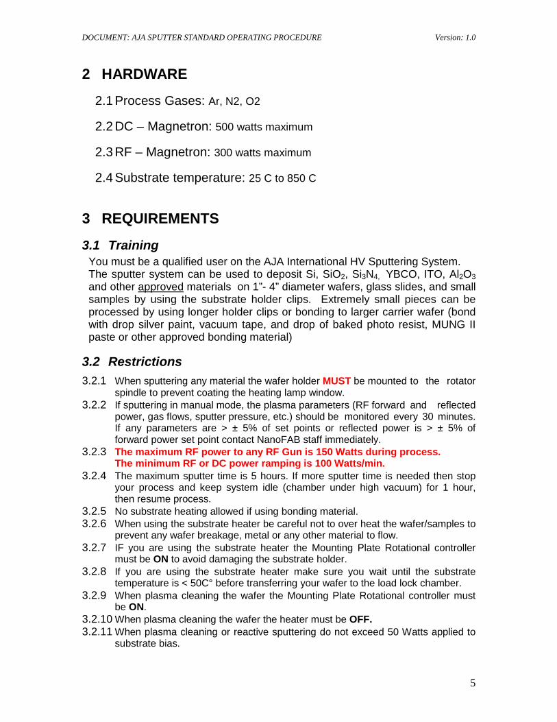
3.3.1 Check to ensure the system water flow interlock light located on the top panel is OFF.
3.3.2 Check to ensure system MAINS POWER switches/breakers (PD-30A, PD-30S) are in the ON position.
3.3.3 Check to ensure the Main Chamber Lid is closed and locked, and Load Lock lid is set in Load Lock chamber.
3.3.4 Check to ensure switches/breakers for VACUUM PUMPS/ MAIN CHAMBER (PD-30A) and VACUUM PUMPS/ LOAD LOCK (PD-30S) are in the ON position.
Fig 3.3.1 - 3.3.4 Fig 3.3.5
3.3.5 Check to ensure the system lap top computer is on and displays Microsoft desktop screen.
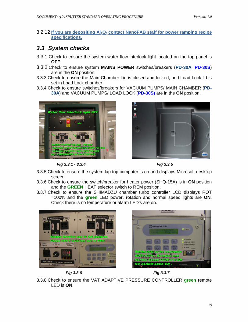
3.3.6 Check to ensure the switch/breaker for heater power (SHQ-15A) is in ON position and the GREEN HEAT selector switch to REM position.
3.3.7 Check to ensure the SHIMADZU chamber turbo controller LCD displays ROT =100% and the green LED power, rotation and normal speed lights are ON. Check there is no temperature or alarm LED’s are on.
Fig 3.3.6 Fig 3.3.7
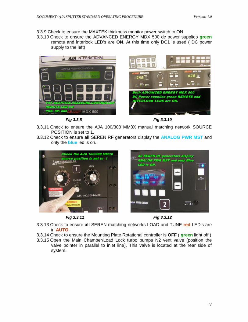
3.3.8 Check to ensure the VAT ADAPTIVE PRESSURE CONTROLLER green remote LED is ON.
DOCUMENT: AJA SPUTTER STANDARD OPERATING PROCEDURE Version: 1.0
7
3.3.9 Check to ensure the MAXTEK thickness monitor power switch to ON 3.3.10 Check to ensure the ADVANCED ENERGY MDX 500 dc power supplies green
remote and interlock LED’s are ON. At this time only DC1 is used ( DC power supply to the left)
Fig 3.3.8 Fig 3.3.10
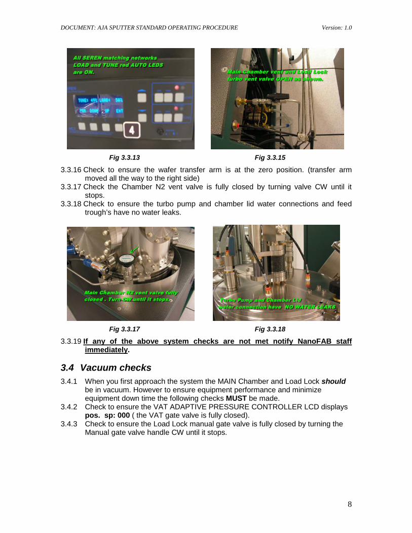
3.3.11 Check to ensure the AJA 100/300 MM3X manual matching network SOURCE POSITION is set to 1.
3.3.12 Check to ensure all SEREN RF generators display the ANALOG PWR MST and only the blue led is on.
Fig 3.3.11 Fig 3.3.12
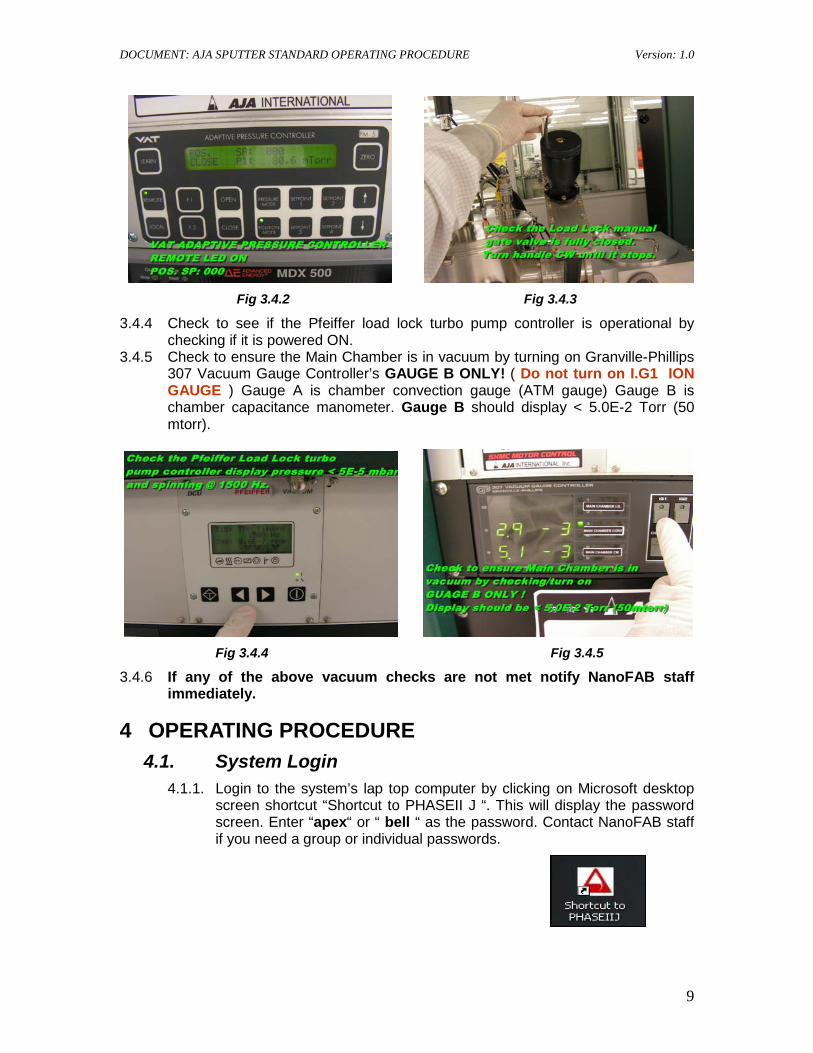
3.3.13 Check to ensure all SEREN matching networks LOAD and TUNE red LED’s are in AUTO.
3.3.14 Check to ensure the Mounting Plate Rotational controller is OFF ( green light off ) 3.3.15 Open the Main Chamber/Load Lock turbo pumps N2 vent valve (position the
valve pointer in parallel to inlet line). This valve is located at the rear side of system.
DOCUMENT: AJA SPUTTER STANDARD OPERATING PROCEDURE Version: 1.0
8
Fig 3.3.13 Fig 3.3.15
3.3.16 Check to ensure the wafer transfer arm is at the zero position. (transfer arm moved all the way to the right side)
3.3.17 Check the Chamber N2 vent valve is fully closed by turning valve CW until it stops.
3.3.18 Check to ensure the turbo pump and chamber lid water connections and feed trough’s have no water leaks.
Fig 3.3.17 Fig 3.3.18
3.3.19 If any of the above system checks are not met notify NanoFAB staff immediately
3.4 Vacuum checks
.
3.4.1 When you first approach the system the MAIN Chamber and Load Lock should be in vacuum. However to ensure equipment performance and minimize equipment down time the following checks MUST be made.
3.4.2 Check to ensure the VAT ADAPTIVE PRESSURE CONTROLLER LCD displays pos. sp: 000 ( the VAT gate valve is fully closed).
3.4.3 Check to ensure the Load Lock manual gate valve is fully closed by turning the Manual gate valve handle CW until it stops.
DOCUMENT: AJA SPUTTER STANDARD OPERATING PROCEDURE Version: 1.0
9
Fig 3.4.2 Fig 3.4.3
3.4.4 Check to see if the Pfeiffer load lock turbo pump controller is operational by checking if it is powered ON.
3.4.5 Check to ensure the Main Chamber is in vacuum by turning on Granville-Phillips 307 Vacuum Gauge Controller’s GAUGE B ONLY! ( Do not turn on I.G1 ION GAUGE ) Gauge A is chamber convection gauge (ATM gauge) Gauge B is chamber capacitance manometer. Gauge B should display < 5.0E-2 Torr (50 mtorr).
Fig 3.4.4 Fig 3.4.5
3.4.6 If any of the above vacuum checks are not met notify NanoFAB staff immediately.
4 OPERATING PROCEDURE 4.1. System Login
4.1.1. Login to the system’s lap top computer by clicking on Microsoft desktop screen shortcut “Shortcut to PHASEII J “. This will display the password screen. Enter “apex“ or “ bell “ as the password. Contact NanoFAB staff if you need a group or individual passwords.
DOCUMENT: AJA SPUTTER STANDARD OPERATING PROCEDURE Version: 1.0
10
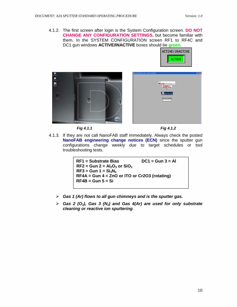
4.1.2. The first screen after login is the System Configuration screen. DO NOT CHANGE ANY CONFIGURATION SETTINGS, but become familiar with them. In the SYSTEM CONFIGURATION screen RF1 to RF4C and DC1 gun windows ACTIVE/INACTIVE boxes should be green.
Fig 4.1.1 Fig 4.1.2
4.1.3. If they are not call NanoFAB staff immediately. Always check the posted NanoFAB engineering change notices (ECN) since the sputter gun configurations change weekly due to target schedules or tool troubleshooting tests.
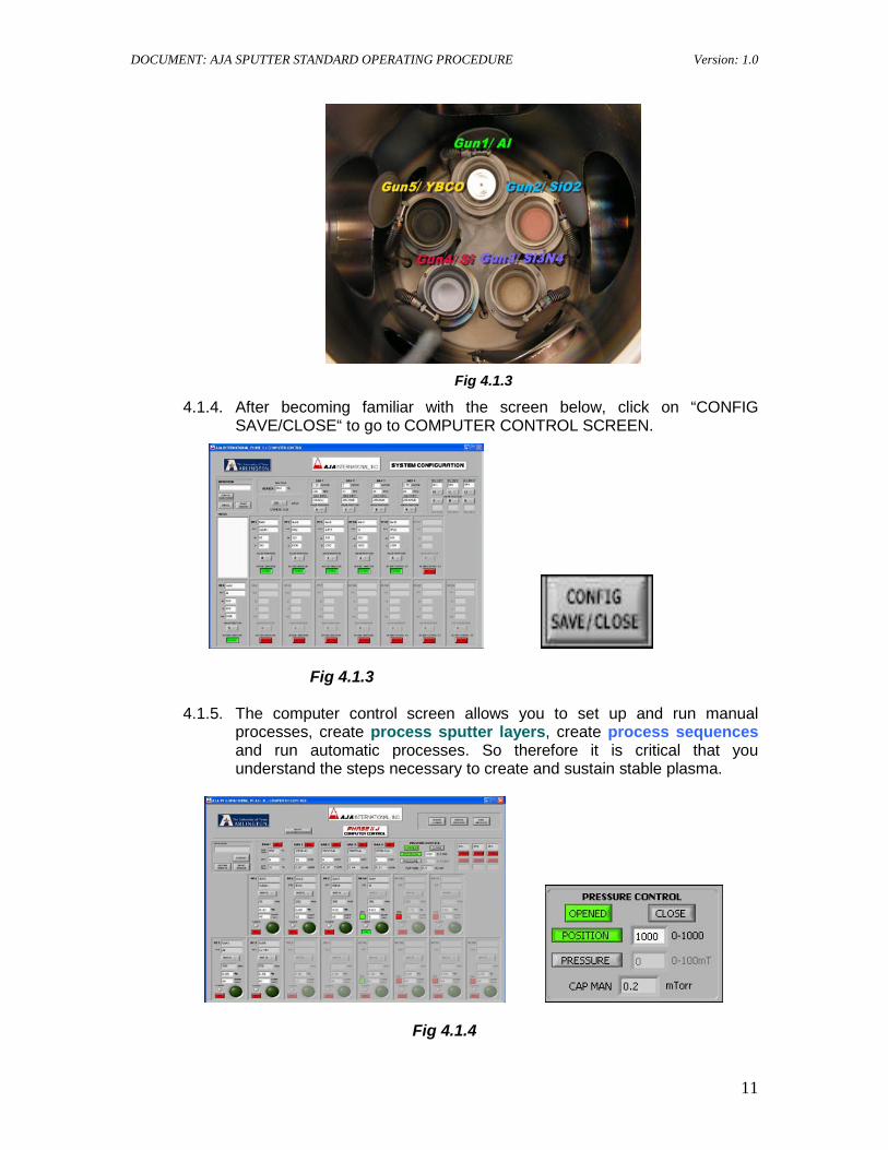
Gas 1 (Ar) flows to all gun chimneys and is the sputter gas. Gas 2 (O2), Gas 3 (N2) and Gas 4(Ar) are used for only substrate
cleaning or reactive ion sputtering.
RF1 = Substrate Bias DC1 = Gun 3 = Al RF2 = Gun 2 = Al2O3 or SiO2 RF3 = Gun 1 = Si3N4 RF4A = Gun 4 = ZnO or ITO or Cr2O3 (rotating)
RF4B = Gun 5 = Si
DOCUMENT: AJA SPUTTER STANDARD OPERATING PROCEDURE Version: 1.0
11
Fig 4.1.3
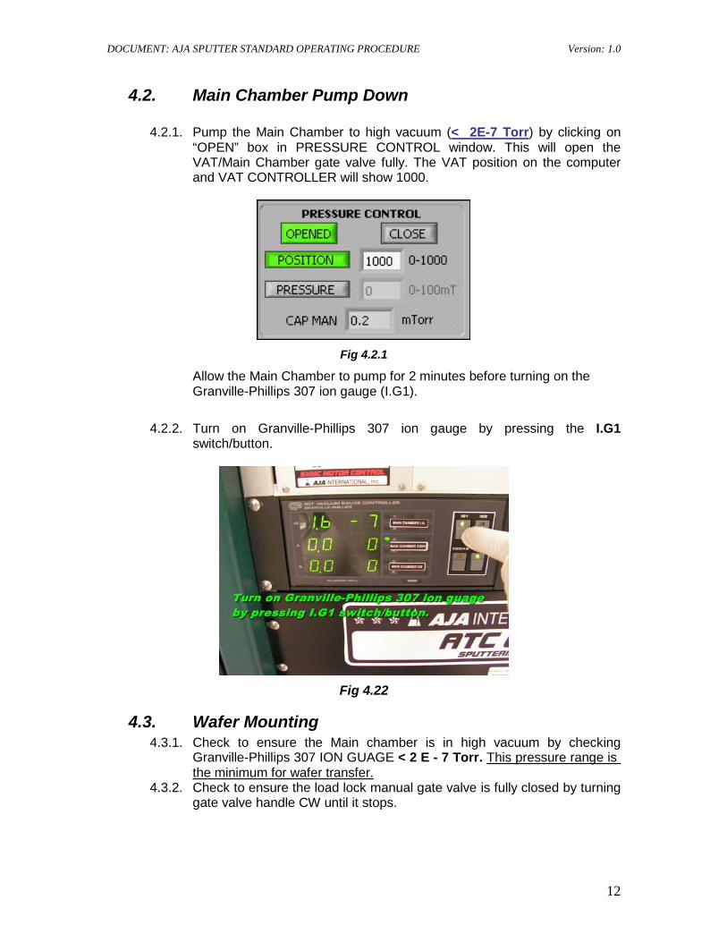
4.1.4. After becoming familiar with the screen below, click on “CONFIG SAVE/CLOSE“ to go to COMPUTER CONTROL SCREEN.
Fig 4.1.3
4.1.5. The computer control screen allows you to set up and run manual processes, create process sputter layers, create process sequences and run automatic processes. So therefore it is critical that you understand the steps necessary to create and sustain stable plasma.
Fig 4.1.4
DOCUMENT: AJA SPUTTER STANDARD OPERATING PROCEDURE Version: 1.0
12
4.2. Main Chamber Pump Down
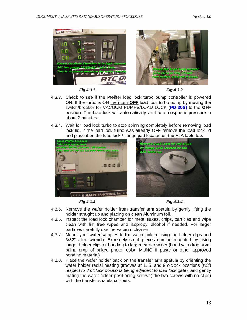
4.2.1. Pump the Main Chamber to high vacuum (< 2E-7 Torr
) by clicking on “OPEN” box in PRESSURE CONTROL window. This will open the VAT/Main Chamber gate valve fully. The VAT position on the computer and VAT CONTROLLER will show 1000.
Fig 4.2.1
Allow the Main Chamber to pump for 2 minutes before turning on the Granville-Phillips 307 ion gauge (I.G1).
4.2.2. Turn on Granville-Phillips 307 ion gauge by pressing the I.G1 switch/button.
Fig 4.22
4.3. Wafer Mounting 4.3.1. Check to ensure the Main chamber is in high vacuum by checking
Granville-Phillips 307 ION GUAGE < 2 E - 7 Torr. This pressure range is
4.3.2. Check to ensure the load lock manual gate valve is fully closed by turning gate valve handle CW until it stops.
the minimum for wafer transfer.
DOCUMENT: AJA SPUTTER STANDARD OPERATING PROCEDURE Version: 1.0
13
Fig 4.3.1 Fig 4.3.2
4.3.3. Check to see if the Pfeiffer load lock turbo pump controller is powered ON. If the turbo is ON then turn OFF
4.3.4. Wait for load lock turbo to stop spinning completely before removing load lock lid. If the load lock turbo was already OFF remove the load lock lid and place it on the load lock / flange pad located on the AJA table top.
load lock turbo pump by moving the switch/breaker for VACUUM PUMPS/LOAD LOCK (PD-30S) to the OFF position. The load lock will automatically vent to atmospheric pressure in about 2 minutes.
Fig 4.3.3 Fig 4.3.4
4.3.5. Remove the wafer holder from transfer arm spatula by gently lifting the holder straight up and placing on clean Aluminum foil.
4.3.6. Inspect the load lock chamber for metal flakes, chips, particles and wipe clean with lint free wipes and isopropyl alcohol if needed. For larger particles carefully use the vacuum cleaner.
4.3.7. Mount your wafer/samples to the wafer holder using the holder clips and 3/32” allen wrench. Extremely small pieces can be mounted by using longer holder clips or bonding to larger carrier wafer (bond with drop silver paint, drop of baked photo resist, MUNG II paste or other approved bonding material)
4.3.8. Place the wafer holder back on the transfer arm spatula by orienting the wafer holder radial heating grooves at 1, 5, and 9 o’clock positions (with respect to 3 o’clock positions being adjacent to load lock gate) and gently mating the wafer holder positioning screws( the two screws with no clips) with the transfer spatula cut-outs.
DOCUMENT: AJA SPUTTER STANDARD OPERATING PROCEDURE Version: 1.0
14
Fig 4.3.5 Fig 4.3.7
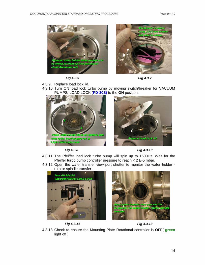
4.3.9. Replace load lock lid. 4.3.10. Turn ON load lock turbo pump by moving switch/breaker for VACUUM
PUMPS/ LOAD LOCK (PD-30S) to the ON position.
Fig 4.3.8 Fig 4.3.10
4.3.11. The Pfeiffer load lock turbo pump will spin up to 1500Hz. Wait for the Pfeiffer turbo pump controller pressure to reach < 2 E-5 mbar.
4.3.12. Open the wafer transfer view port shutter to monitor the wafer holder - rotator spindle transfer.
Fig 4.3.11 Fig 4.3.13
4.3.13. Check to ensure the Mounting Plate Rotational controller is OFF( green light off )
DOCUMENT: AJA SPUTTER STANDARD OPERATING PROCEDURE Version: 1.0
15
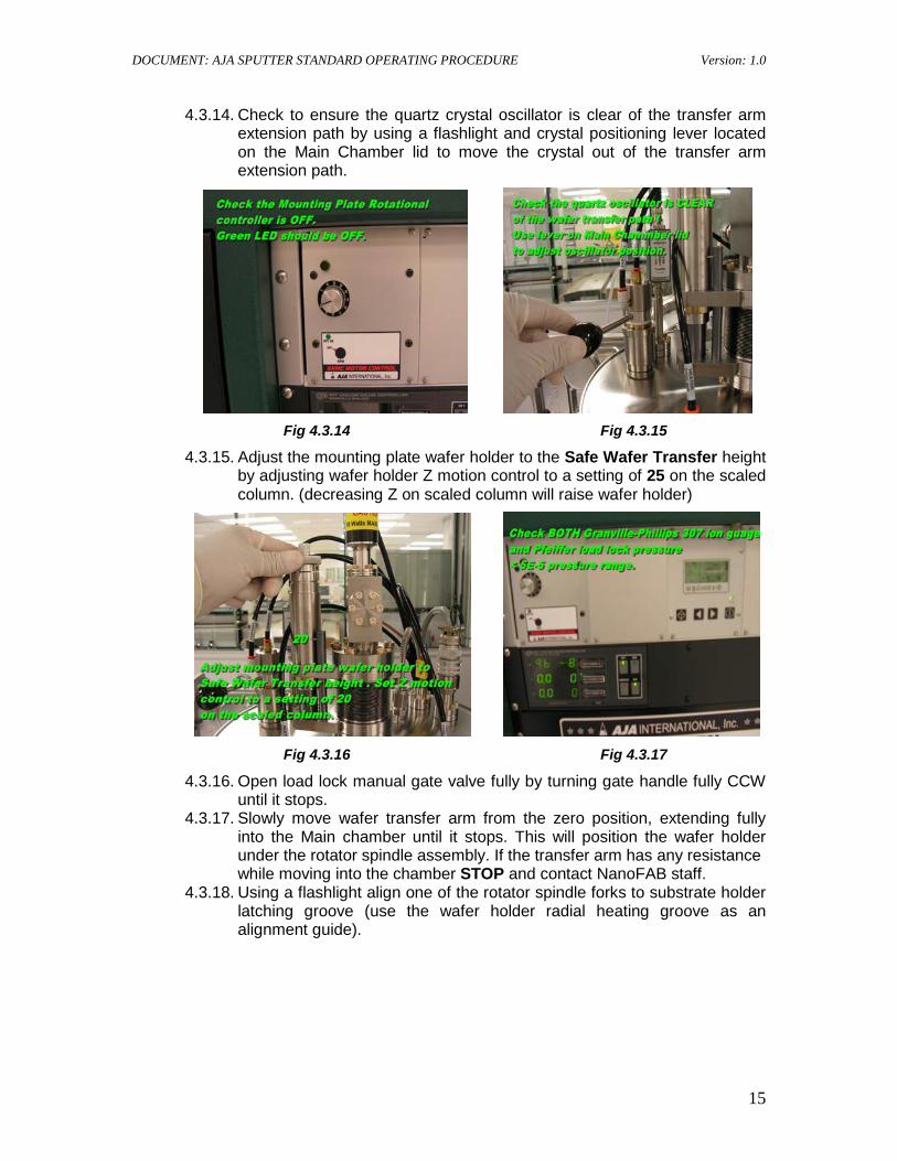
4.3.14. Check to ensure the quartz crystal oscillator is clear of the transfer arm extension path by using a flashlight and crystal positioning lever located on the Main Chamber lid to move the crystal out of the transfer arm extension path.
Fig 4.3.14 Fig 4.3.15
4.3.15. Adjust the mounting plate wafer holder to the Safe Wafer Transfer height by adjusting wafer holder Z motion control to a setting of 25 on the scaled column. (decreasing Z on scaled column will raise wafer holder)
Fig 4.3.16 Fig 4.3.17
4.3.16. Open load lock manual gate valve fully by turning gate handle fully CCW until it stops.
4.3.17. Slowly move wafer transfer arm from the zero position, extending fully into the Main chamber until it stops. This will position the wafer holder under the rotator spindle assembly. If the transfer arm has any resistance
while moving into the chamber STOP and contact NanoFAB staff. 4.3.18. Using a flashlight align one of the rotator spindle forks to substrate holder
latching groove (use the wafer holder radial heating groove as an alignment guide).
DOCUMENT: AJA SPUTTER STANDARD OPERATING PROCEDURE Version: 1.0
16
Fig 4.3.18 Fig 4.3.19
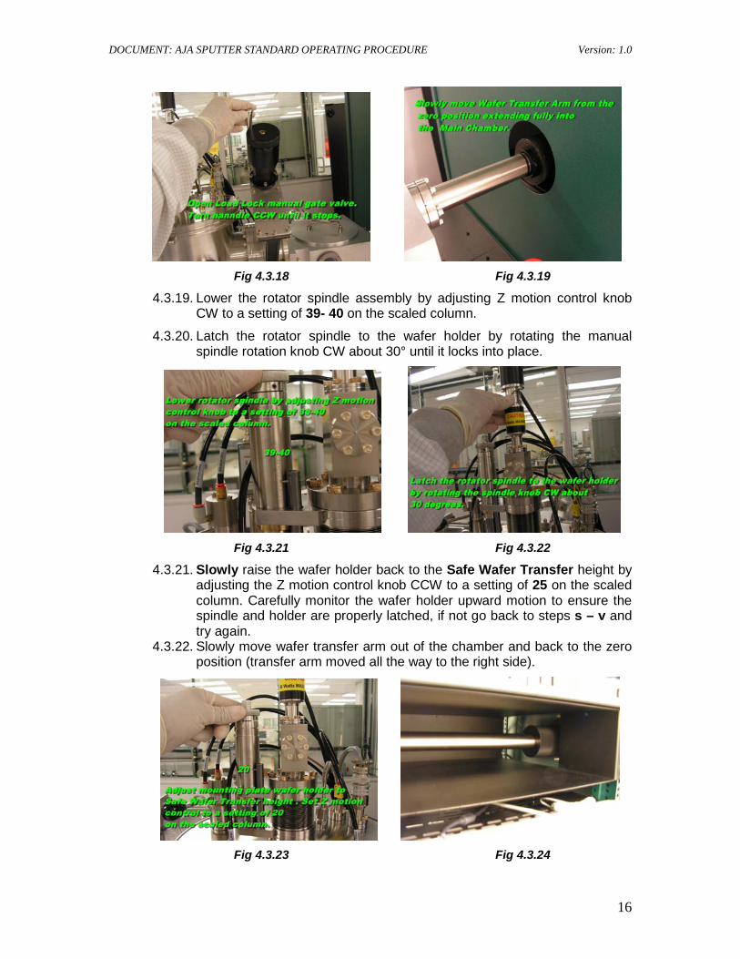
4.3.19. Lower the rotator spindle assembly by adjusting Z motion control knob CW to a setting of 39- 40 on the scaled column.
4.3.20. Latch the rotator spindle to the wafer holder by rotating the manual spindle rotation knob CW about 30° until it locks into place.
Fig 4.3.21 Fig 4.3.22
4.3.21. Slowly raise the wafer holder back to the Safe Wafer Transfer height by adjusting the Z motion control knob CCW to a setting of 25 on the scaled column. Carefully monitor the wafer holder upward motion to ensure the spindle and holder are properly latched, if not go back to steps s – v and try again.
4.3.22. Slowly move wafer transfer arm out of the chamber and back to the zero position (transfer arm moved all the way to the right side).
Fig 4.3.23 Fig 4.3.24
DOCUMENT: AJA SPUTTER STANDARD OPERATING PROCEDURE Version: 1.0
17
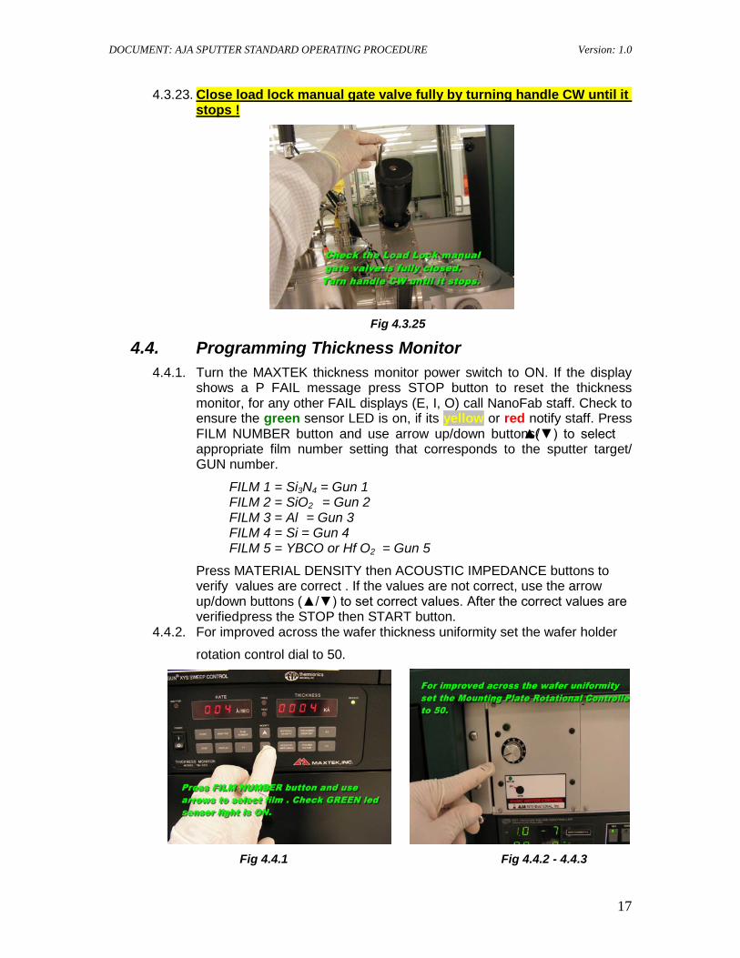
4.3.23. Close load lock manual gate valve fully by turning handle CW until it stops !
Fig 4.3.25
4.4. Programming Thickness Monitor 4.4.1. Turn the MAXTEK thickness monitor power switch to ON. If the display
shows a P FAIL message press STOP button to reset the thickness monitor, for any other FAIL displays (E, I, O) call NanoFab staff. Check to ensure the green sensor LED is on, if its yellow or red notify staff. Press FILM NUMBER button and use arrow up/down buttons(▲/▼) to select appropriate film number setting that corresponds to the sputter target/ GUN number.
FILM 1 = Si3N4 = Gun 1 FILM 2 = SiO2 = Gun 2 FILM 3 = Al = Gun 3 FILM 4 = Si = Gun 4 FILM 5 = YBCO or Hf O2 = Gun 5
Press MATERIAL DENSITY then ACOUSTIC IMPEDANCE buttons to verify values are correct . If the values are not correct, use the arrow up/down buttons (▲/▼) to set correct values. After the correct values are verified press the STOP then START button.
4.4.2. For improved across the wafer thickness uniformity set the wafer holder
rotation control dial to 50.
Fig 4.4.1 Fig 4.4.2 - 4.4.3
DOCUMENT: AJA SPUTTER STANDARD OPERATING PROCEDURE Version: 1.0
18
4.4.3. If you are using the substrate heater the wafer rotation must be ON to avoid damage to the wafer holder. Set the Mounting Plate Rotational control dial to 50.
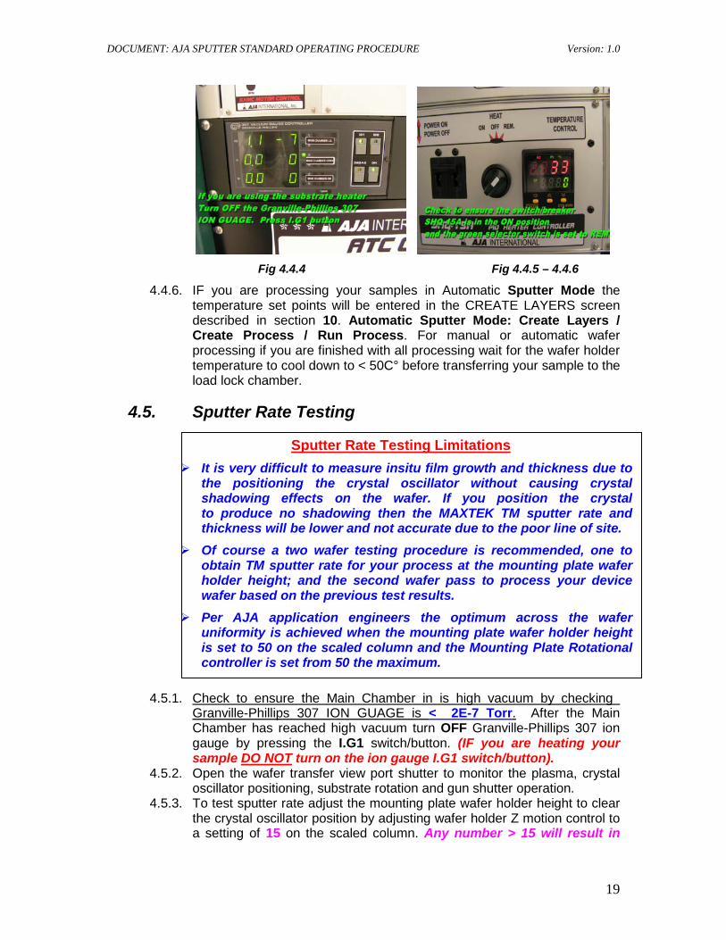
4.4.4. If you are heating your substrate/sample check to ensure the Main Chamber in is high vacuum by checking Granville-Phillips 307 ION GUAGE is < 2E-7 Torr
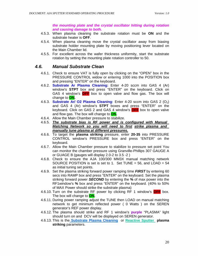
4.4.5. To heat your substrate check to ensure the switch/breaker for heater power (SHQ-15A) is in ON position and the GREEN HEAT selector switch to REM position.
. After the Main Chamber has reached high vacuum turn OFF Granville-Phillips 307 ion gauge by pressing the I.G1 switch/button.
( IF you are heating your sample DO NOT
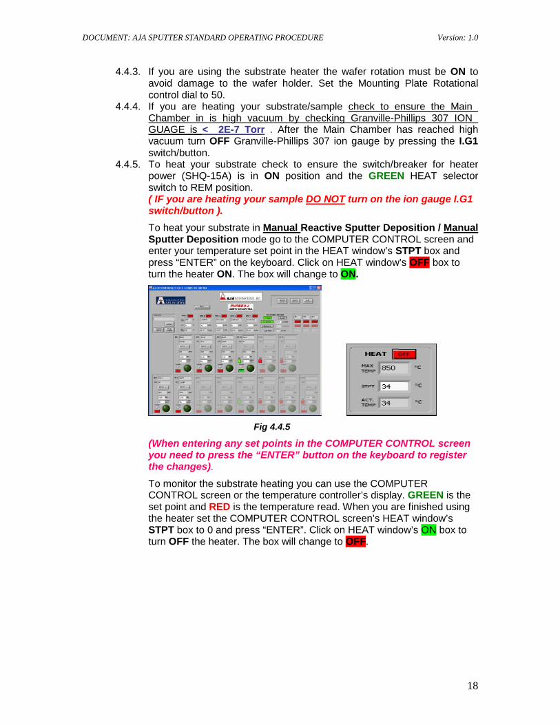
To heat your substrate in
turn on the ion gauge I.G1 switch/button ).
Manual Reactive Sputter Deposition / Manual
Sputter Deposition mode go to the COMPUTER CONTROL screen and enter your temperature set point in the HEAT window’s STPT box and press “ENTER” on the keyboard. Click on HEAT window’s OFF box to turn the heater ON. The box will change to ON.
Fig 4.4.5
(When entering any set points in the COMPUTER CONTROL screen you need to press the “ENTER” button on the keyboard to register the changes). To monitor the substrate heating you can use the COMPUTER CONTROL screen or the temperature controller’s display. GREEN is the set point and RED is the temperature read. When you are finished using the heater set the COMPUTER CONTROL screen’s HEAT window’s STPT box to 0 and press “ENTER”. Click on HEAT window’s ON box to turn OFF the heater. The box will change to OFF.
DOCUMENT: AJA SPUTTER STANDARD OPERATING PROCEDURE Version: 1.0
19
Fig 4.4.4 Fig 4.4.5 – 4.4.6
4.4.6. IF you are processing your samples in Automatic Sputter Mode the temperature set points will be entered in the CREATE LAYERS screen described in section 10. Automatic Sputter Mode: Create Layers / Create Process / Run Process. For manual or automatic wafer processing if you are finished with all processing wait for the wafer holder temperature to cool down to < 50C° before transferring your sample to the load lock chamber.
4.5. Sputter Rate Testing
4.5.1. Check to ensure the Main Chamber in is high vacuum by checking Granville-Phillips 307 ION GUAGE is < 2E-7 Torr. After the Main Chamber has reached high vacuum turn OFF Granville-Phillips 307 ion gauge by pressing the I.G1 switch/button. (IF you are heating your sample DO NOT
4.5.2. Open the wafer transfer view port shutter to monitor the plasma, crystal oscillator positioning, substrate rotation and gun shutter operation.
turn on the ion gauge I.G1 switch/button).
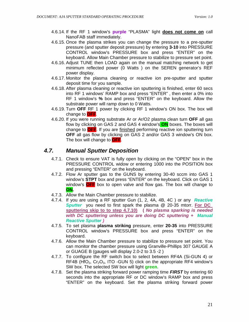
4.5.3. To test sputter rate adjust the mounting plate wafer holder height to clear the crystal oscillator position by adjusting wafer holder Z motion control to a setting of 15 on the scaled column. Any number > 15 will result in
Sputter Rate Testing Limitations It is very difficult to measure insitu film growth and thickness due to
the positioning the crystal oscillator without causing crystal shadowing effects on the wafer. If you position the crystal to produce no shadowing then the MAXTEK TM sputter rate and thickness will be lower and not accurate due to the poor line of site.
Of course a two wafer testing procedure is recommended, one to obtain TM sputter rate for your process at the mounting plate wafer holder height; and the second wafer pass to process your device wafer based on the previous test results.
Per AJA application engineers the optimum across the wafer uniformity is achieved when the mounting plate wafer holder height is set to 50 on the scaled column and the Mounting Plate Rotational controller is set from 50 the maximum.
DOCUMENT: AJA SPUTTER STANDARD OPERATING PROCEDURE Version: 1.0
20
the mounting plate and the crystal oscillator hitting during rotation and causing damage to both.
4.5.3. When plasma cleaning the substrate rotation must be ON and the substrate heater is OFF.
4.5.4. When plasma cleaning move the crystal oscillator away from biasing substrate holder mounting plate by moving positioning lever located on the Main Chamber lid.
4.5.5. For excellent across the wafer thickness uniformity, start the substrate rotation by setting the mounting plate rotation controller to 50.
4.6. Manual Substrate Clean 4.6.1. Check to ensure VAT is fully open by clicking on the “OPEN” box in the
PRESSURE CONTROL widow or entering 1000 into the POSITION box and pressing “ENTER” on the keyboard.
4.6.2. Substrate Ar Plasma Cleaning: Enter 4-20 sccm into GAS 4 (Ar) window’s STPT box and press “ENTER” on the keyboard. Click on GAS 4 window’s OFF box to open valve and flow gas. The box will change to ON.
4.6.3. Substrate Ar/ O2 Plasma Cleaning: Enter 4-20 sccm into GAS 2 (O2) and GAS 4 (Ar) window’s STPT boxes and press “ENTER” on the keyboard. Click on GAS 2 and GAS 4 window’s OFF box to open valve and flow gas. The box will change to ON.
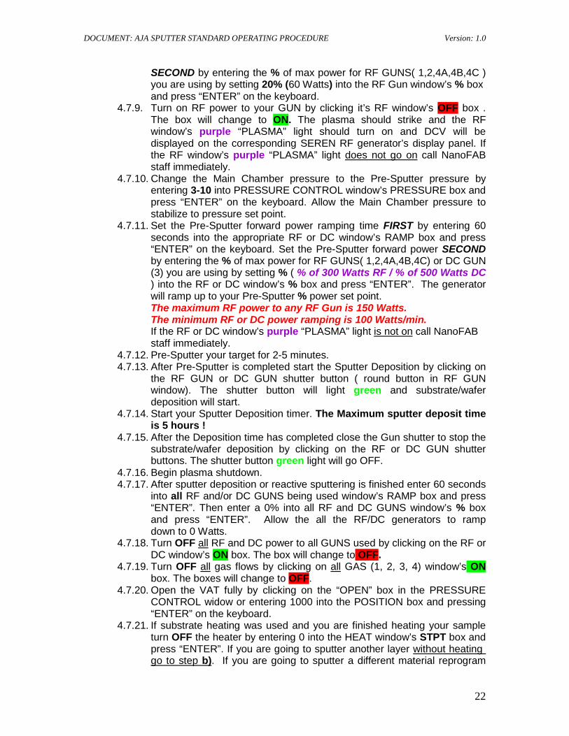
4.6.4. Allow the Main Chamber pressure to stabilize. 4.6.5. The substrate bias is RF power and is configured with Manual
Matching Network so you will need to first strike plasma and
4.6.6. To target the plasma striking pressure, enter 20-35 into PRESSURE CONTROL window’s PRESSURE box and press “ENTER” on the keyboard.
manually tune plasma at different pressures.
4.6.7. Allow the Main Chamber pressure to stabilize to pressure set point You can monitor the chamber pressure using Granville-Phillips 307 GAUGE A or GUAGE B (gauges will display 2.0-2 to 3.5 -2 )
4.6.8. Check to ensure the AJA 100/300 MM3X manual matching network SOURCE POSITION is set is set to 1. Set TUNE = 56, and LOAD = 54 as initial tuning set points.
4.6.9. Set the plasma striking forward power ramping time FIRST by entering 60 secs into RAMP box and press “ENTER” on the keyboard. Set the plasma striking forward power SECOND by entering the % of max power into the RF1window’s % box and press “ENTER” on the keyboard. (40% to 50% of MAX Power should strike the substrate plasma)
4.6.10. Turn on the substrate RF power by clicking RF 1 window’s OFF box. The box will change to ON.
4.6.11. During power ramping adjust the TUNE then LOAD on manual matching network to get minimum reflected power ( 0 Watts ) on the SEREN generator’s REF power display.
4.6.12. The plasma should strike and RF 1 window’s purple “PLASMA” light should turn on and DCV will be displayed on SEREN generator.
4.6.13. This is the Substrate Plasma Cleaning or Reactive Sputter plasma striking parameters.
DOCUMENT: AJA SPUTTER STANDARD OPERATING PROCEDURE Version: 1.0
21
4.6.14. If the RF 1 window’s purple “PLASMA” light does not come on
4.6.15. Once the plasma strikes you can change the pressure to a pre-sputter pressure (and sputter deposit pressure) by entering 3-10 into PRESSURE CONTROL window’s PRESSURE box and press “ENTER” on the keyboard. Allow Main Chamber pressure to stabilize to pressure set point.
call NanoFAB staff immediately.
4.6.16. Adjust TUNE then LOAD again on the manual matching network to get minimum reflected power (0 Watts ) on the SEREN generator’s REF power display.
4.6.17. Monitor the plasma cleaning or reactive ion pre-sputter and sputter deposit time for you sample.
4.6.18. After plasma cleaning or reactive ion sputtering is finished, enter 60 secs into RF 1 windows’ RAMP box and press “ENTER” , then enter a 0% into RF 1 window’s % box and press “ENTER” on the keyboard. Allow the substrate power will ramp down to 0 Watts.
4.6.19. Turn OFF RF 1 power by clicking RF 1 window’s ON box. The box will change to OFF.
4.6.20. If you were running substrate Ar or Ar/O2 plasma clean turn OFF all gas flow by clicking on GAS 2 and GAS 4 window’s ON boxes. The boxes will change to OFF. If you are finished
4.7. Manual Sputter Deposition
performing reactive ion sputtering turn OFF all gas flow by clicking on GAS 2 and/or GAS 3 window’s ON box. The box will change to OFF.
4.7.1. Check to ensure VAT is fully open by clicking on the “OPEN” box in the PRESSURE CONTROL widow or entering 1000 into the POSITION box and pressing “ENTER” on the keyboard.
4.7.2. Flow Ar sputter gas to the GUNS by entering 30-40 sccm into GAS 1 window’s STPT box and press “ENTER” on the keyboard. Click on GAS 1 window’s OFF box to open valve and flow gas. The box will change to ON.
4.7.3. Allow the Main Chamber pressure to stabilize. 4.7.4. If you are using a RF sputter Gun (1, 2, 4A, 4B, 4C ) or any Reactive
Sputter you need to first spark the plasma @ 20-35 mtorr. For DC sputtering skip to to step 4.7.10)
4.7.5. To set plasma plasma striking pressure, enter 20-35 into PRESSURE CONTROL window’s PRESSURE box and press “ENTER” on the keyboard.
( No plasma sparking is needed with DC sputtering unless you are doing DC sputtering + Manual Reactive Sputter )
4.7.6. Allow the Main Chamber pressure to stabilize to pressure set point. You can monitor the chamber pressure using Granville-Phillips 307 GAUGE A or GUAGE B (gauges will display 2.0-2 to 3.5 -2 )
4.7.7. To configure the RF switch box to select between RF4A (Si-GUN 4) or RF4B (HfO2, Cr2O3, ITO -GUN 5) click on the appropriate RF4 window’s SW box. The selected SW box will light green.
4.7.8. Set the plasma striking forward power ramping time FIRST by entering 60 seconds into the appropriate RF or DC window’s RAMP box and press “ENTER” on the keyboard. Set the plasma striking forward power
DOCUMENT: AJA SPUTTER STANDARD OPERATING PROCEDURE Version: 1.0
22
SECOND by entering the % of max power for RF GUNS( 1,2,4A,4B,4C ) you are using by setting 20% (60 Watts) into the RF Gun window’s % box
and press “ENTER” on the keyboard. 4.7.9. Turn on RF power to your GUN by clicking it’s RF window’s OFF box .
The box will change to ON. The plasma should strike and the RF window’s purple “PLASMA” light should turn on and DCV will be displayed on the corresponding SEREN RF generator’s display panel. If the RF window’s purple “PLASMA” light does not go on
4.7.10. Change the Main Chamber pressure to the Pre-Sputter pressure by entering 3-10 into PRESSURE CONTROL window’s PRESSURE box and press “ENTER” on the keyboard. Allow the Main Chamber pressure to stabilize to pressure set point.
call NanoFAB staff immediately.
4.7.11. Set the Pre-Sputter forward power ramping time FIRST by entering 60 seconds into the appropriate RF or DC window’s RAMP box and press “ENTER” on the keyboard. Set the Pre-Sputter forward power SECOND by entering the % of max power for RF GUNS( 1,2,4A,4B,4C) or DC GUN (3) you are using by setting % ( % of 300 Watts RF / % of 500 Watts DC ) into the RF or DC window’s % box and press “ENTER”. The generator will ramp up to your Pre-Sputter % power set point.
The maximum RF power to any RF Gun is 150 Watts. The minimum RF or DC power ramping is 100 Watts/min.
If the RF or DC window’s purple “PLASMA” light is not on
4.7.12. Pre-Sputter your target for 2-5 minutes.
call NanoFAB staff immediately.
4.7.13. After Pre-Sputter is completed start the Sputter Deposition by clicking on the RF GUN or DC GUN shutter button ( round button in RF GUN window). The shutter button will light green and substrate/wafer deposition will start.
4.7.14. Start your Sputter Deposition timer. The Maximum sputter deposit time is 5 hours !
4.7.15. After the Deposition time has completed close the Gun shutter to stop the substrate/wafer deposition by clicking on the RF or DC GUN shutter buttons. The shutter button green light will go OFF.
4.7.16. Begin plasma shutdown. 4.7.17. After sputter deposition or reactive sputtering is finished enter 60 seconds
into all RF and/or DC GUNS being used window’s RAMP box and press “ENTER”. Then enter a 0% into all RF and DC GUNS window’s % box and press “ENTER”. Allow the all the RF/DC generators to ramp down to 0 Watts.
4.7.18. Turn OFF all
4.7.19. Turn OFF
RF and DC power to all GUNS used by clicking on the RF or DC window’s ON box. The box will change to OFF.
all gas flows by clicking on all
4.7.20. Open the VAT fully by clicking on the “OPEN” box in the PRESSURE CONTROL widow or entering 1000 into the POSITION box and pressing “ENTER” on the keyboard.
GAS (1, 2, 3, 4) window’s ON box. The boxes will change to OFF.
4.7.21. If substrate heating was used and you are finished heating your sample turn OFF the heater by entering 0 into the HEAT window’s STPT box and press “ENTER”. If you are going to sputter another layer without heating go to step b). If you are going to sputter a different material reprogram
DOCUMENT: AJA SPUTTER STANDARD OPERATING PROCEDURE Version: 1.0
23
the MAXTEK thickness monitor by pressing FILM NUMBER button and use arrow up/down buttons(▲/▼) to select the appropriate film number setting that corresponds to the sputter target/ GUN number. If you are finished with all processing wait for the wafer holder temperature to cool down to < 50 C° before transferring your sample to the load lock chamber.
4.7.22. If you are not finished using the substrate heater and you are going to sputter another layer make any changes to the HEAT window’s STPT box and press “ENTER” then go to step 4.5.2)
4.7.23. If you are finished with the processing of all layers, continue to Wafer Transfer Section (Main Chamber to Load Lock Transfer).
. If you are going to sputter a different material, reprogram the MAXTEK thickness monitor.
4.8. Reactive Sputter 4.8.1. Depending on your process enter 4-20 sccm into GAS 2 (O2) and/or GAS
3 (N2) window’s STPT box and press “ENTER” on the keyboard. Click on GAS 2 and/or GAS 3 window’s OFF box to open valve and flow gas. The box will change to ON.
4.8.2. Allow the Main Chamber pressure to stabilize. 4.8.3. The substrate bias is RF power and is configured with Manual
Matching Network so you will need to first strike plasma and
4.8.4. To target the plasma striking pressure, enter 20-35 into PRESSURE CONTROL window’s PRESSURE box and press “ENTER” on the keyboard.
manually tune plasma at different pressures.
4.8.5. Allow the Main Chamber pressure to stabilize to pressure set point You can monitor the chamber pressure using Granville-Phillips 307 GAUGE A or GUAGE B (gauges will display 2.0-2 to 3.5 -2 )
4.8.6. Check to ensure the AJA 100/300 MM3X manual matching network SOURCE POSITION is set is set to 1. Set TUNE = 56, and LOAD = 54 as initial tuning set points.
4.8.7. Set the plasma striking forward power ramping time FIRST by entering 60 secs into RAMP box and press “ENTER” on the keyboard. Set the plasma striking forward power SECOND by entering the % of max power into the RF1window’s % box and press “ENTER” on the keyboard. (40% to 50% of MAX Power should strike the substrate plasma)
4.8.8. Turn on the substrate RF power by clicking RF 1 window’s OFF box. The box will change to ON.
4.8.9. During power ramping adjust the TUNE then LOAD on manual matching network to get minimum reflected power ( 0 Watts ) on the SEREN generator’s REF power display.
4.8.10. The plasma should strike and RF 1 window’s purple “PLASMA” light should turn on and DCV will be displayed on SEREN generator.
4.8.11. This is the Substrate Plasma Cleaning or Reactive Sputter
4.8.12. If the RF 1 window’s purple “PLASMA” light
plasma striking parameters.
does not go on
4.8.13. Once the plasma strikes you can change the pressure to a pre-sputter pressure (and sputter deposit pressure) by entering 3-10 into PRESSURE
call NanoFAB staff immediately.
DOCUMENT: AJA SPUTTER STANDARD OPERATING PROCEDURE Version: 1.0
24
CONTROL window’s PRESSURE box and press “ENTER” on the keyboard. Allow Main Chamber pressure to stabilize to pressure set point.
4.8.14. Adjust TUNE then LOAD again on the manual matching network to get minimum reflected power (0 Watts) on the SEREN generator’s REF power display.
4.8.15. Monitor the plasma cleaning or reactive ion pre-sputter and sputter deposit time for you sample.
4.8.16. After plasma cleaning or reactive ion sputtering is finished, enter 60 secs into RF 1 windows’ RAMP box and press “ENTER” , then enter a 0% into RF 1 window’s % box and press “ENTER” on the keyboard. Allow the substrate power will ramp down to 0 Watts.
4.8.17. Turn OFF RF 1 power by clicking RF 1 window’s ON box. The box will change to OFF.
4.8.18. If you were running substrate Ar or Ar/O2 plasma clean turn OFF all gas flow by clicking on GAS 2 and GAS 4 window’s ON boxes. The boxes will change to OFF. If you are finished
4.8.19. Flow Ar sputter gas to the GUNS by entering 30-40 sccm into GAS 1 window’s STPT box and press “ENTER” on the keyboard. Click on GAS 1 window’s OFF box to open valve and flow gas. The box will change to ON.
performing reactive ion sputtering turn OFF all gas flow by clicking on GAS 2 and/or GAS 3 window’s ON box. The box will change to OFF.
4.8.20. Allow the Main Chamber pressure to stabilize. 4.8.21. If you are using a RF sputter Gun (1, 2, 4A, 4B, 4C) or any Reactive
Sputter you need to first spark the plasma @ 20-35 mtorr. For DC sputtering skip to to step ll)
4.8.22. To set plasma plasma striking pressure, enter 20-35 into PRESSURE CONTROL window’s PRESSURE box and press “ENTER” on the keyboard.
( No plasma sparking is needed with DC sputtering unless you are doing DC sputtering + Manual Reactive Sputter )
4.8.23. Allow the Main Chamber pressure to stabilize to pressure set point. You can monitor the chamber pressure using Granville-Phillips 307 GAUGE A or GUAGE B (gauges will display 2.0-2 to 3.5 -2 )
4.8.24. To configure the RF switch box to select between RF4A (Si-GUN 4 ) or RF4B (HfO2 ,Cr2O3 , ITO -GUN 5) click on the appropriate RF4 window’s SW box. The selected SW box will light green.
4.8.25. Set the plasma striking forward power ramping time FIRST by entering 60 seconds into the appropriate RF or DC window’s RAMP box and press “ENTER” on the keyboard. Set the plasma striking forward power SECOND by entering the % of max power for RF GUNS( 1,2,4A,4B,4C ) you are using by setting 20% (60 Watts) into the RF Gun window’s % box
and press “ENTER” on the keyboard. 4.8.26. Turn on RF power to your GUN by clicking it’s RF window’s OFF box.
The box will change to ON. The plasma should strike and the RF window’s purple “PLASMA” light should turn on and DCV will be displayed on the corresponding SEREN RF generator’s display panel. If the RF window’s purple “PLASMA” light does not go on
4.8.27. Change the Main Chamber pressure to the Pre-Sputter pressure by entering 3-10 into PRESSURE CONTROL window’s PRESSURE box and
call NanoFAB staff immediately.
DOCUMENT: AJA SPUTTER STANDARD OPERATING PROCEDURE Version: 1.0
25
press “ENTER” on the keyboard. Allow the Main Chamber pressure to stabilize to pressure set point.
4.8.28. Set the Pre-Sputter forward power ramping time FIRST by entering 60 seconds into the appropriate RF or DC window’s RAMP box and press “ENTER” on the keyboard. Set the Pre-Sputter forward power SECOND by entering the % of max power for RF GUNS (1, 2, 4A, 4B, 4C) or DC GUN (3) you are using by setting % (% of 300 Watts RF / % of 500 Watts DC) into the RF or DC window’s % box and press “ENTER”. The generator will ramp up to your Pre-Sputter % power set point.
The maximum RF power to any RF Gun is 150 Watts. The minimum RF or DC power ramping is 100 Watts/min.
If the RF or DC window’s purple “PLASMA” light is not on
4.8.29. Pre-Sputter your target for 2-5 minutes.
call NanoFAB staff immediately.
4.8.30. After Pre-Sputter is completed start the Sputter Deposition by clicking on the RF GUN or DC GUN shutter button ( round button in RF GUN window). The shutter button will light green and substrate/wafer deposition will start.
4.8.31. Start your Sputter Deposition timer. The Maximum sputter deposit time is 5 hours !
4.8.32. After the Deposition time has completed close the Gun shutter to stop the substrate/wafer deposition by clicking on the RF or DC GUN shutter buttons. The shutter button green light will go OFF.
4.8.33. Begin plasma shutdown. 4.8.34. After sputter deposition or reactive sputtering is finished enter 60 seconds
into all RF and/or DC GUNS being used window’s RAMP box and press “ENTER”. Then enter a 0% into all RF and DC GUNS window’s % box and press “ENTER”. Allow the all the RF/DC generators to ramp down to 0 Watts.
4.8.35. Turn OFF all
4.8.36. Turn OFF
RF and DC power to all GUNS used by clicking on the RF or DC window’s ON box. The box will change to OFF.
all gas flows by clicking on all
4.8.37. Open the VAT fully by clicking on the “OPEN” box in the PRESSURE CONTROL widow or entering 1000 into the POSITION box and pressing “ENTER” on the keyboard.
GAS (1, 2, 3, 4) window’s ON box. The boxes will change to OFF.
4.8.38. If substrate heating was used and you are finished heating your sample turn OFF the heater by entering 0 into the HEAT window’s STPT box and press “ENTER”. If you are going to sputter another layer without heating go to step b)
. If you are going to sputter a different material reprogram the MAXTEK thickness monitor by pressing FILM NUMBER button and use arrow up/down buttons(▲/▼) to select the appropriate film number setting that corresponds to the sputter target/ GUN number. If you are finished with all processing wait for the wafer holder temperature to cool down to < 50 C° before transferring your sample to the load lock chamber.
DOCUMENT: AJA SPUTTER STANDARD OPERATING PROCEDURE Version: 1.0
26
4.9. Automatic Sputter Mode 4.9.1. Check to ensure VAT is fully open by clicking on the “OPEN” box in the
PRESSURE CONTROL widow or entering 1000 into the POSITION box and pressing “ENTER” on the keyboard.
4.9.2. Check to ensure the Main Chamber in is high vacuum (< 2E-7 Torr) by pressing the Granville-Phillips 307 ION GUAGE I.G1 switch/button. After the Main Chamber has reached high vacuum turn OFF Granville-Phillips 307 ion gauge I.G1 switch/button. IF you are heating your wafer/sample DO NOT
4.9.3. Review section Sputter Rate Testing for any adjustments. turn on the ion gauge.
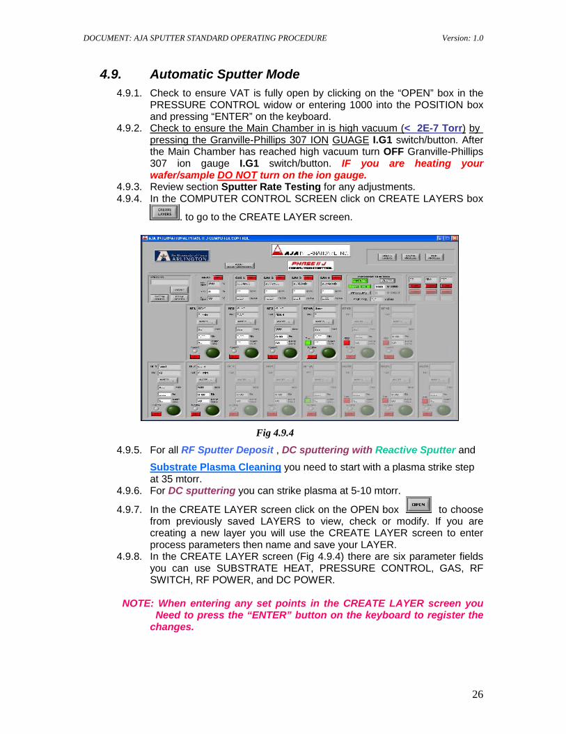
4.9.4. In the COMPUTER CONTROL SCREEN click on CREATE LAYERS box
. to go to the CREATE LAYER screen.
Fig 4.9.4
4.9.5. For all RF Sputter Deposit , DC sputtering with Reactive Sputter and
Substrate Plasma Cleaning
4.9.6. For DC sputtering you can strike plasma at 5-10 mtorr.
you need to start with a plasma strike step at 35 mtorr.
4.9.7. In the CREATE LAYER screen click on the OPEN box to choose from previously saved LAYERS to view, check or modify. If you are creating a new layer you will use the CREATE LAYER screen to enter process parameters then name and save your LAYER.
4.9.8. In the CREATE LAYER screen (Fig 4.9.4) there are six parameter fields you can use SUBSTRATE HEAT, PRESSURE CONTROL, GAS, RF SWITCH, RF POWER, and DC POWER.
NOTE: When entering any set points in the CREATE LAYER screen you
Need to press the “ENTER” button on the keyboard to register the changes.
DOCUMENT: AJA SPUTTER STANDARD OPERATING PROCEDURE Version: 1.0
27
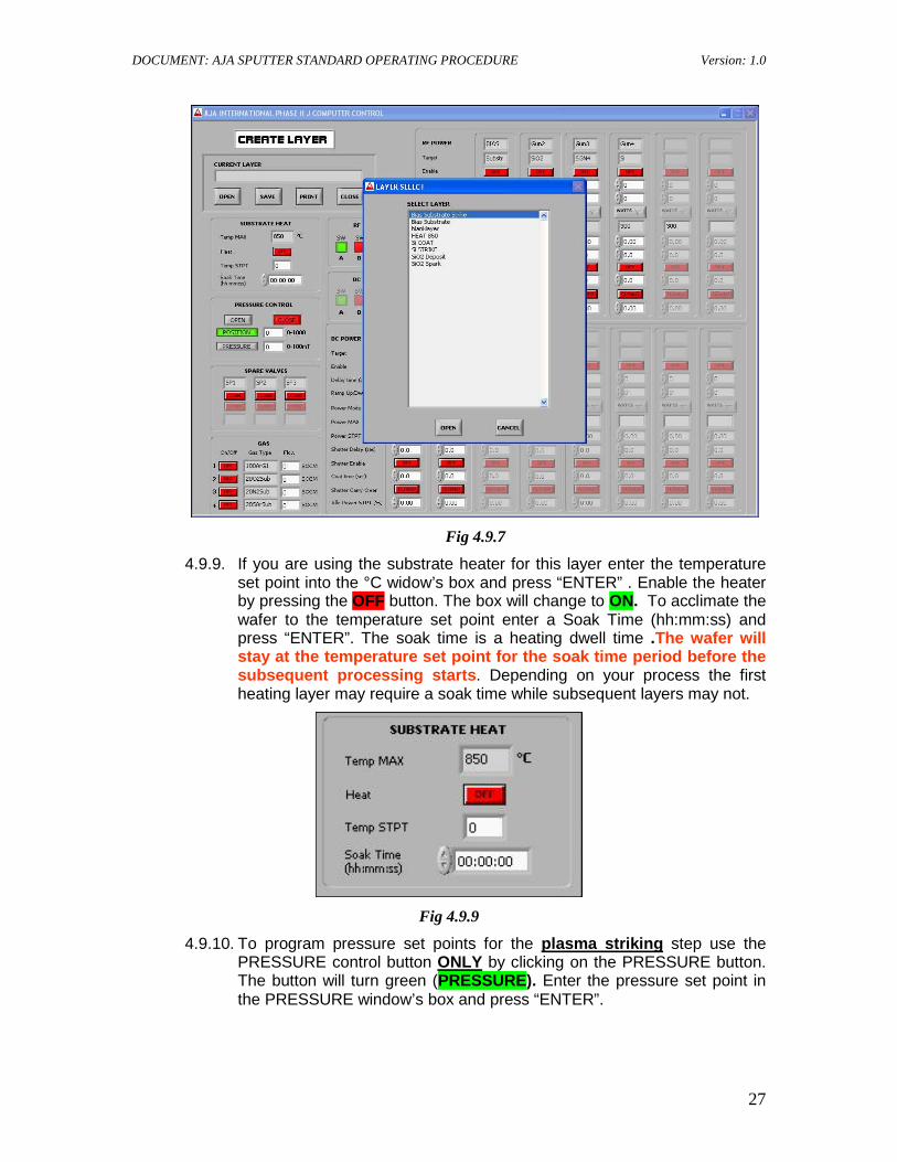
Fig 4.9.7
4.9.9. If you are using the substrate heater for this layer enter the temperature set point into the °C widow’s box and press “ENTER” . Enable the heater by pressing the OFF button. The box will change to ON. To acclimate the wafer to the temperature set point enter a Soak Time (hh:mm:ss) and press “ENTER”. The soak time is a heating dwell time .The wafer will stay at the temperature set point for the soak time period before the subsequent processing starts. Depending on your process the first heating layer may require a soak time while subsequent layers may not.
Fig 4.9.9
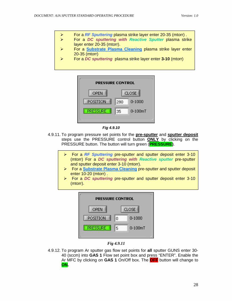
4.9.10. To program pressure set points for the plasma striking step use the PRESSURE control button ONLY
by clicking on the PRESSURE button. The button will turn green (PRESSURE). Enter the pressure set point in the PRESSURE window’s box and press “ENTER”.
DOCUMENT: AJA SPUTTER STANDARD OPERATING PROCEDURE Version: 1.0
28
Fig 4.9.10
4.9.11. To program pressure set points for the pre-sputter and sputter deposit steps use the PRESSURE control button ONLY
by clicking on the PRESSURE button. The button will turn green (PRESSURE).
Fig 4.9.11
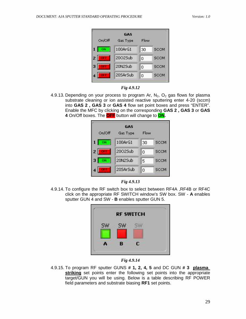
4.9.12. To program Ar sputter gas flow set points for all sputter GUNS enter 30- 40 (sccm) into GAS 1 Flow set point box and press “ENTER”. Enable the Ar MFC by clicking on GAS 1 On/Off box. The OFF button will change to ON.
For a RF Sputtering pre-sputter and sputter deposit enter 3-10 (mtorr) For a DC sputtering with Reactive sputter pre-sputter and sputter deposit enter 3-10 (mtorr).
For a Substrate Plasma Cleaning pre-sputter and sputter deposit enter 10-20 (mtorr) .
For a DC sputtering pre-sputter and sputter deposit enter 3-10 (mtorr).
For a RF Sputtering plasma strike layer enter 20-35 (mtorr) . For a DC sputtering with Reactive Sputter plasma strike
layer enter 20-35 (mtorr). For a Substrate Plasma Cleaning plasma strike layer enter
20-35 (mtorr) For a DC sputtering plasma strike layer enter 3-10 (mtorr)
DOCUMENT: AJA SPUTTER STANDARD OPERATING PROCEDURE Version: 1.0
29
Fig 4.9.12
4.9.13. Depending on your process to program Ar, N2, O2 gas flows for plasma substrate cleaning or ion assisted reactive sputtering enter 4-20 (sccm) into GAS 2 , GAS 3 or GAS 4 flow set point boxes and press “ENTER”. Enable the MFC by clicking on the corresponding GAS 2 , GAS 3 or GAS 4 On/Off boxes. The OFF button will change to ON.
Fig 4.9.13
4.9.14. To configure the RF switch box to select between RF4A ,RF4B or RF4C click on the appropriate RF SWITCH window’s SW box. SW - A enables sputter GUN 4 and SW - B enables sputter GUN 5.
Fig 4.9.14
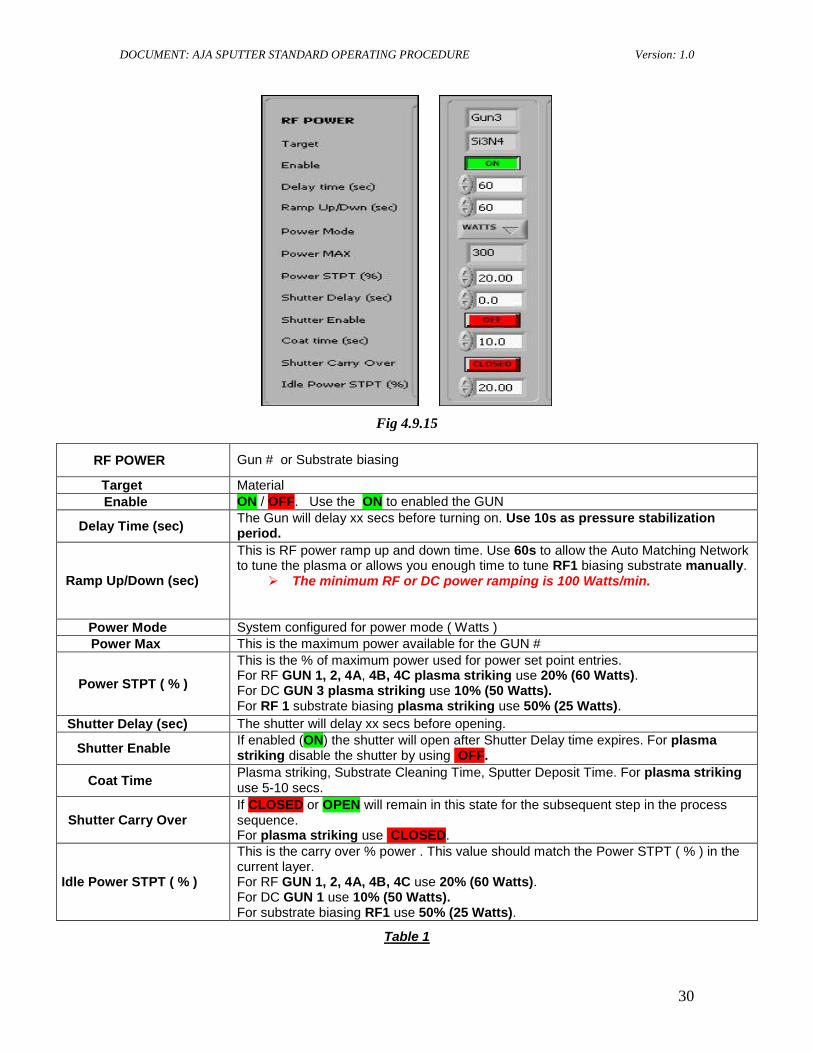
4.9.15. To program RF sputter GUNS # 1, 2, 4, 5 and DC GUN # 3 plasma striking set points enter the following set points into the appropriate target/GUN you will be using. Below is a table describing RF POWER field parameters and substrate biasing RF1 set points.
DOCUMENT: AJA SPUTTER STANDARD OPERATING PROCEDURE Version: 1.0
30
Fig 4.9.15
RF POWER
Table 1
Gun # or Substrate biasing
Target Material Enable ON / OFF. Use the ON to enabled the GUN
Delay Time (sec) The Gun will delay xx secs before turning on. Use 10s as pressure stabilization period.
Ramp Up/Down (sec)
This is RF power ramp up and down time. Use 60s to allow the Auto Matching Network to tune the plasma or allows you enough time to tune RF1 biasing substrate manually.
The minimum RF or DC power ramping is 100 Watts/min.
Power Mode System configured for power mode ( Watts ) Power Max This is the maximum power available for the GUN #
Power STPT ( % )
This is the % of maximum power used for power set point entries. For RF GUN 1, 2, 4A, 4B, 4C plasma striking use 20% (60 Watts). For DC GUN 3 plasma striking use 10% (50 Watts). For RF 1 substrate biasing plasma striking use 50% (25 Watts).
Shutter Delay (sec) The shutter will delay xx secs before opening.
Shutter Enable If enabled (ON) the shutter will open after Shutter Delay time expires. For plasma striking disable the shutter by using OFF.
Coat Time Plasma striking, Substrate Cleaning Time, Sputter Deposit Time. For plasma striking use 5-10 secs.
Shutter Carry Over If CLOSED or OPEN will remain in this state for the subsequent step in the process sequence. For plasma striking use CLOSED.
Idle Power STPT ( % )
This is the carry over % power . This value should match the Power STPT ( % ) in the current layer. For RF GUN 1, 2, 4A, 4B, 4C use 20% (60 Watts). For DC GUN 1 use 10% (50 Watts). For substrate biasing RF1 use 50% (25 Watts).
DOCUMENT: AJA SPUTTER STANDARD OPERATING PROCEDURE Version: 1.0
31
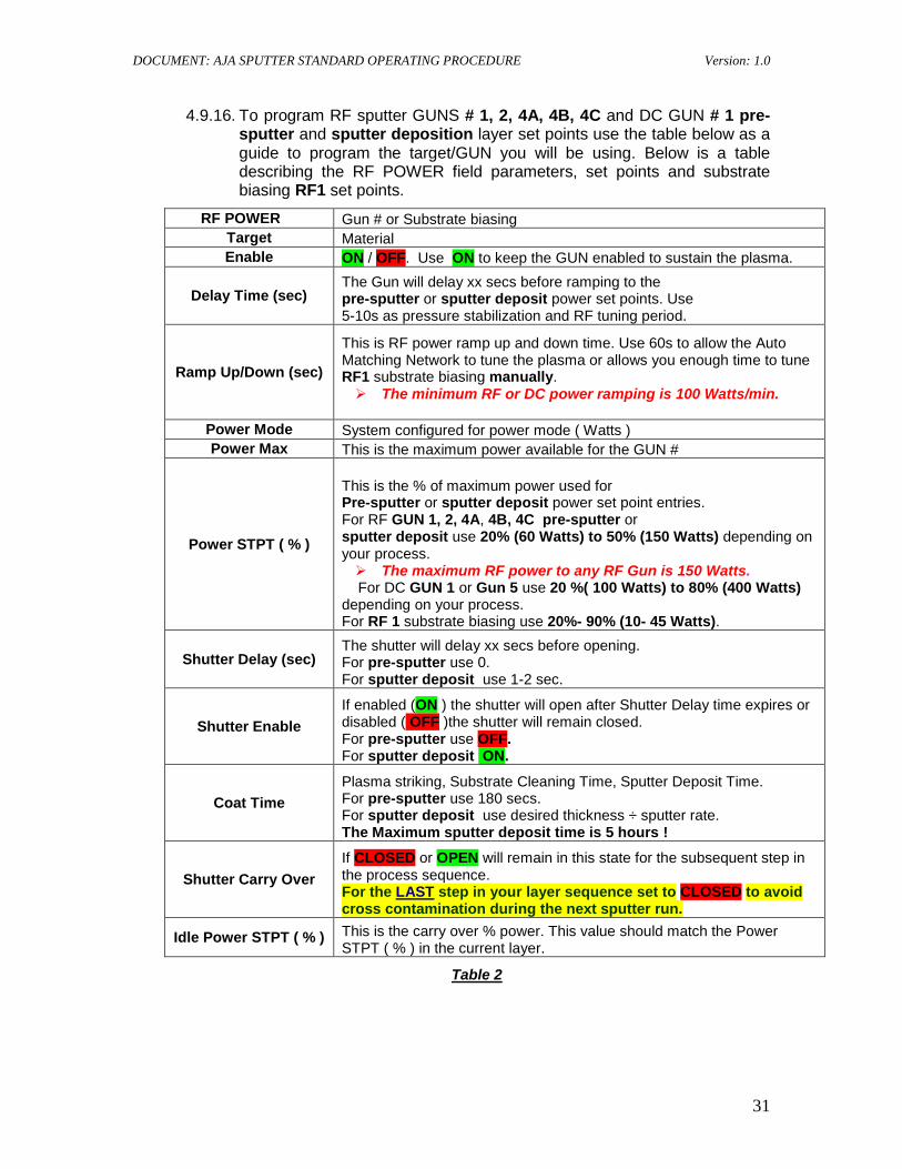
4.9.16. To program RF sputter GUNS # 1, 2, 4A, 4B, 4C and DC GUN # 1 pre- sputter and sputter deposition layer set points use the table below as a guide to program the target/GUN you will be using. Below is a table describing the RF POWER field parameters, set points and substrate biasing RF1 set points.
RF POWER Gun # or Substrate biasing Target Material Enable ON / OFF. Use ON to keep the GUN enabled to sustain the plasma.
Delay Time (sec) The Gun will delay xx secs before ramping to the pre-sputter or sputter deposit power set points. Use 5-10s as pressure stabilization and RF tuning period.
Ramp Up/Down (sec)
This is RF power ramp up and down time. Use 60s to allow the Auto Matching Network to tune the plasma or allows you enough time to tune RF1 substrate biasing manually. The minimum RF or DC power ramping is 100 Watts/min.
Power Mode System configured for power mode ( Watts ) Power Max This is the maximum power available for the GUN #
Power STPT ( % )
This is the % of maximum power used for Pre-sputter or sputter deposit power set point entries. For RF GUN 1, 2, 4A, 4B, 4C pre-sputter or sputter deposit use 20% (60 Watts) to 50% (150 Watts) depending on your process. The maximum RF power to any RF Gun is 150 Watts.
For DC GUN 1 or Gun 5 use 20 %( 100 Watts) to 80% (400 Watts) depending on your process. For RF 1 substrate biasing use 20%- 90% (10- 45 Watts).
Shutter Delay (sec) The shutter will delay xx secs before opening. For pre-sputter use 0. For sputter deposit use 1-2 sec.
Shutter Enable If enabled (ON ) the shutter will open after Shutter Delay time expires or disabled ( OFF )the shutter will remain closed. For pre-sputter use OFF. For sputter deposit ON.
Coat Time Plasma striking, Substrate Cleaning Time, Sputter Deposit Time. For pre-sputter use 180 secs. For sputter deposit use desired thickness ÷ sputter rate. The Maximum sputter deposit time is 5 hours !
Shutter Carry Over If CLOSED or OPEN will remain in this state for the subsequent step in the process sequence. For the LAST step in your layer sequence set to CLOSED to avoid cross contamination during the next sputter run.
Idle Power STPT ( % ) This is the carry over % power. This value should match the Power STPT ( % ) in the current layer.
Table 2
DOCUMENT: AJA SPUTTER STANDARD OPERATING PROCEDURE Version: 1.0
32
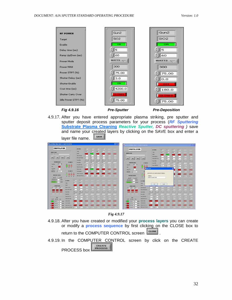
Fig 4.9.16 Pre-Sputter Pre-Deposition
4.9.17. After you have entered appropriate plasma striking, pre sputter and sputter deposit process parameters for your process (RF Sputtering Substrate Plasma Cleaning Reactive Sputter, DC sputtering ) save and name your created layers by clicking on the SAVE box and enter a layer file name.
Fig 4.9.17
4.9.18. After you have created or modified your process layers you can create or modify a process sequence by first clicking on the CLOSE box to
return to the COMPUTER CONTROL screen . 4.9.19. In the COMPUTER CONTROL screen by click on the CREATE
PROCESS box
DOCUMENT: AJA SPUTTER STANDARD OPERATING PROCEDURE Version: 1.0
33
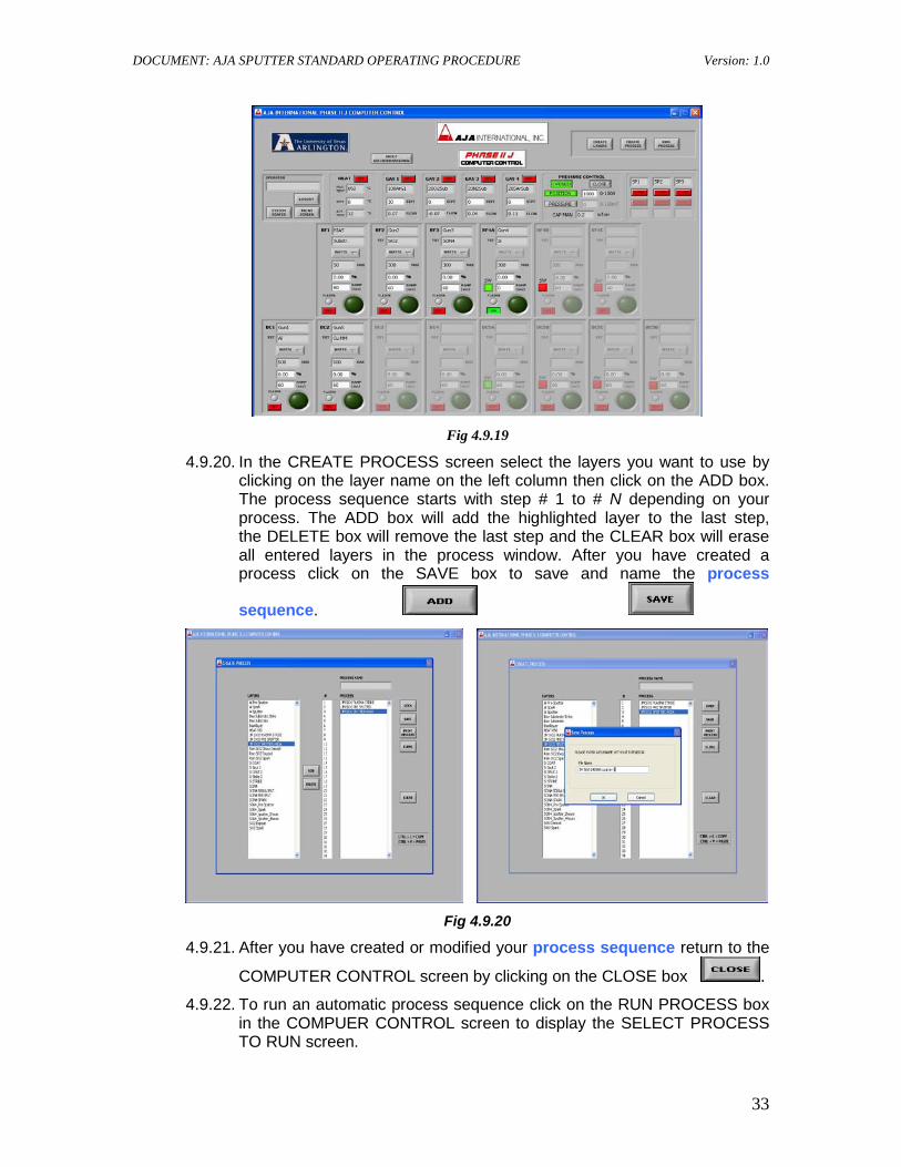
Fig 4.9.19
4.9.20. In the CREATE PROCESS screen select the layers you want to use by clicking on the layer name on the left column then click on the ADD box. The process sequence starts with step # 1 to # N depending on your process. The ADD box will add the highlighted layer to the last step, the DELETE box will remove the last step and the CLEAR box will erase all entered layers in the process window. After you have created a process click on the SAVE box to save and name the process
sequence.
Fig 4.9.20
4.9.21. After you have created or modified your process sequence return to the
COMPUTER CONTROL screen by clicking on the CLOSE box . 4.9.22. To run an automatic process sequence click on the RUN PROCESS box
in the COMPUER CONTROL screen to display the SELECT PROCESS TO RUN screen.
DOCUMENT: AJA SPUTTER STANDARD OPERATING PROCEDURE Version: 1.0
34
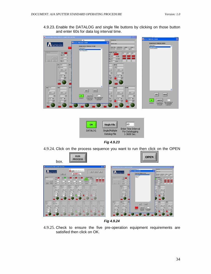
4.9.23. Enable the DATALOG and single file buttons by clicking on those button and enter 60s for data log interval time.
Fig 4.9.23
4.9.24. Click on the process sequence you want to run then click on the OPEN
box.
Fig 4.9.24
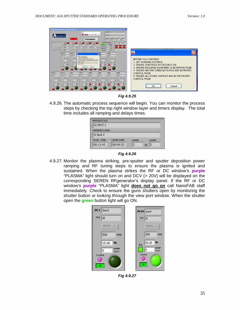
4.9.25. Check to ensure the five pre-operation equipment requirements are satisfied then click on OK.
DOCUMENT: AJA SPUTTER STANDARD OPERATING PROCEDURE Version: 1.0
35
Fig 4.9.25
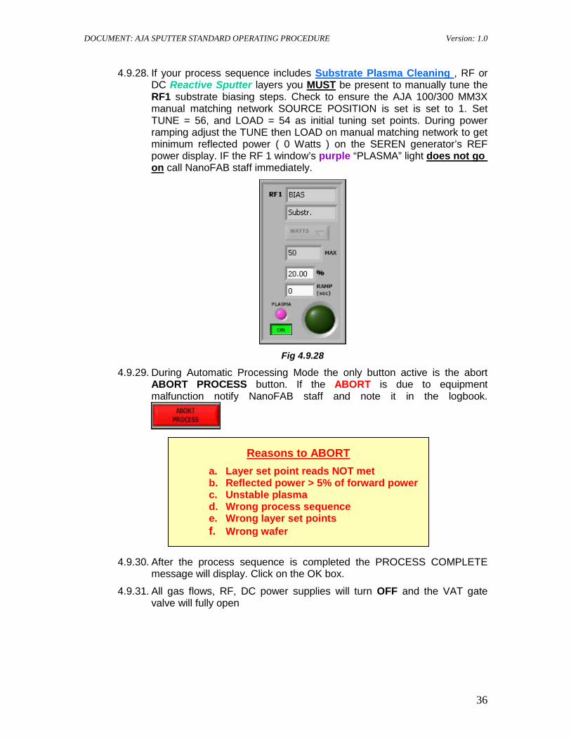
4.9.26. The automatic process sequence will begin. You can monitor the process steps by checking the top right window layer and timers display. The total time includes all ramping and delays times.
Fig 4.9.26
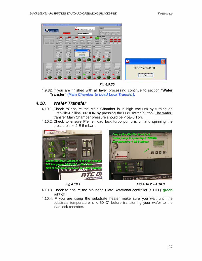
4.9.27. Monitor the plasma striking, pre-sputter and sputter deposition power ramping and RF tuning steps to ensure the plasma is ignited and sustained. When the plasma strikes the RF or DC window’s purple “PLASMA” light should turn on and DCV (> 20V) will be displayed on the corresponding SEREN RFgenerator’s display panel. If the RF or DC window’s purple “PLASMA” light does not go on
call NanoFAB staff immediately. Check to ensure the guns shutters open by monitoring the shutter button or looking through the view port window. When the shutter open the green button light will go ON.
Fig 4.9.27
DOCUMENT: AJA SPUTTER STANDARD OPERATING PROCEDURE Version: 1.0
36
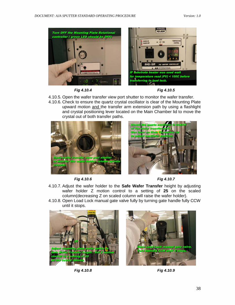
4.9.28. If your process sequence includes Substrate Plasma Cleaning , RF or DC Reactive Sputter layers you MUST be present to manually tune the RF1 substrate biasing steps. Check to ensure the AJA 100/300 MM3X manual matching network SOURCE POSITION is set is set to 1. Set TUNE = 56, and LOAD = 54 as initial tuning set points. During power ramping adjust the TUNE then LOAD on manual matching network to get minimum reflected power ( 0 Watts ) on the SEREN generator’s REF power display. IF the RF 1 window’s purple “PLASMA” light does not go on call NanoFAB staff immediately.
Fig 4.9.28
4.9.29. During Automatic Processing Mode the only button active is the abort ABORT PROCESS button. If the ABORT is due to equipment malfunction notify NanoFAB staff and note it in the logbook.
4.9.30. After the process sequence is completed the PROCESS COMPLETE message will display. Click on the OK box.
4.9.31. All gas flows, RF, DC power supplies will turn OFF and the VAT gate valve will fully open
Reasons to ABORT a. Layer set point reads NOT met b. Reflected power > 5% of forward power c. Unstable plasma d. Wrong process sequence e. Wrong layer set points f. Wrong wafer
DOCUMENT: AJA SPUTTER STANDARD OPERATING PROCEDURE Version: 1.0
37
Fig 4.9.30
4.9.32. If you are finished with all layer processing continue to section “Wafer Transfer” (Main Chamber to Load Lock Transfer).
4.10. Wafer Transfer 4.10.1. Check to ensure the Main Chamber is in high vacuum by turning on
Granville-Phillips 307 ION by pressing the I.G1 switch/button. The wafer
4.10.2. Check to ensure Pfeiffer load lock turbo pump is on and spinning the pressure is < 2 E-5 mbarr.
transfer Main Chamber pressure should be < 5E-6 Torr.
Fig 4.10.1 Fig 4.10.2 – 4.10.3
4.10.3. Check to ensure the Mounting Plate Rotational controller is OFF( green light off )
4.10.4. IF you are using the substrate heater make sure you wait until the substrate temperature is < 50 C° before transferring your wafer to the load lock chamber.
DOCUMENT: AJA SPUTTER STANDARD OPERATING PROCEDURE Version: 1.0
38
Fig 4.10.4 Fig 4.10.5
4.10.5. Open the wafer transfer view port shutter to monitor the wafer transfer. 4.10.6. Check to ensure the quartz crystal oscillator is clear of the Mounting Plate
upward motion and
the transfer arm extension path by using a flashlight and crystal positioning lever located on the Main Chamber lid to move the crystal out of both transfer paths.
Fig 4.10.6 Fig 4.10.7
4.10.7. Adjust the wafer holder to the Safe Wafer Transfer height by adjusting wafer holder Z motion control to a setting of 25 on the scaled column(decreasing Z on scaled column will raise the wafer holder).
4.10.8. Open Load Lock manual gate valve fully by turning gate handle fully CCW until it stops.
Fig 4.10.8 Fig 4.10.9
DOCUMENT: AJA SPUTTER STANDARD OPERATING PROCEDURE Version: 1.0
39
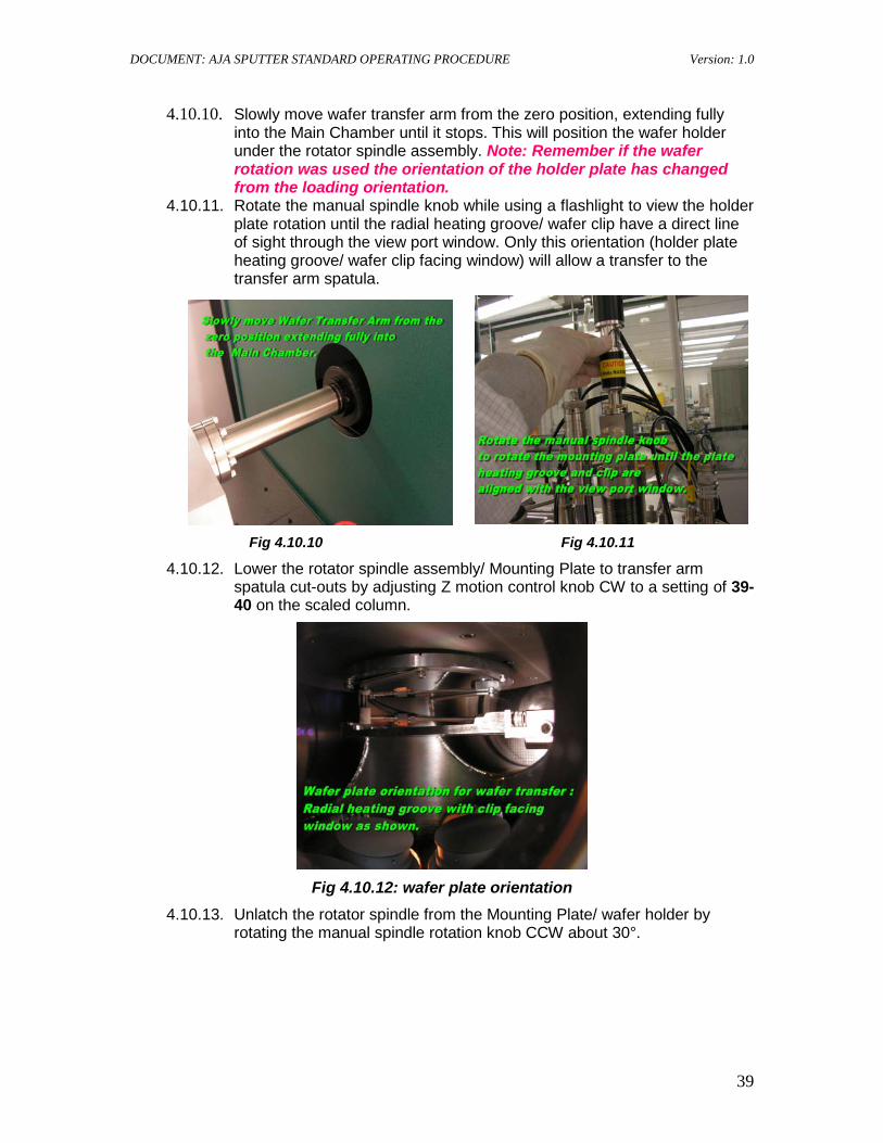
4.10.10. Slowly move wafer transfer arm from the zero position, extending fully into the Main Chamber until it stops. This will position the wafer holder under the rotator spindle assembly. Note: Remember if the wafer rotation was used the orientation of the holder plate has changed from the loading orientation.
4.10.11. Rotate the manual spindle knob while using a flashlight to view the holder plate rotation until the radial heating groove/ wafer clip have a direct line of sight through the view port window. Only this orientation (holder plate heating groove/ wafer clip facing window) will allow a transfer to the transfer arm spatula.
Fig 4.10.10 Fig 4.10.11
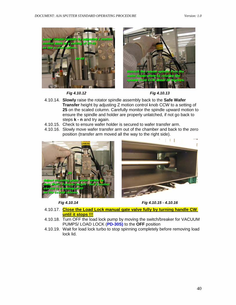
4.10.12. Lower the rotator spindle assembly/ Mounting Plate to transfer arm spatula cut-outs by adjusting Z motion control knob CW to a setting of 39- 40 on the scaled column.
Fig 4.10.12: wafer plate orientation
4.10.13. Unlatch the rotator spindle from the Mounting Plate/ wafer holder by rotating the manual spindle rotation knob CCW about 30°.
DOCUMENT: AJA SPUTTER STANDARD OPERATING PROCEDURE Version: 1.0
40
Fig 4.10.12 Fig 4.10.13
4.10.14. Slowly raise the rotator spindle assembly back to the Safe Wafer Transfer height by adjusting Z motion control knob CCW to a setting of 25 on the scaled column. Carefully monitor the spindle upward motion to ensure the spindle and holder are properly unlatched, if not go back to steps k - n and try again.
4.10.15. Check to ensure wafer holder is secured to wafer transfer arm. 4.10.16. Slowly move wafer transfer arm out of the chamber and back to the zero
position (transfer arm moved all the way to the right side).
Fig 4.10.14 Fig 4.10.15 - 4.10.16
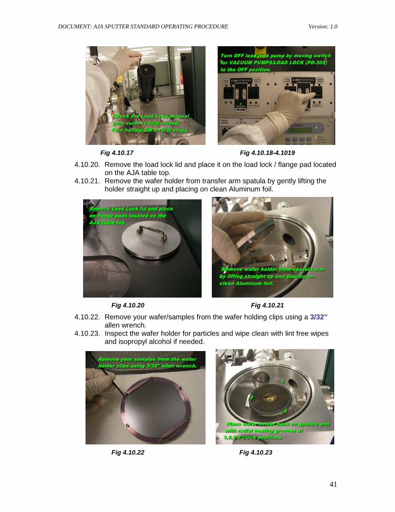
4.10.17. Close the Load Lock manual gate valve fully by turning handle CW
4.10.18. Turn OFF the load lock pump by moving the switch/breaker for VACUUM PUMPS/ LOAD LOCK (PD-30S) to the OFF position
until it stops !!!
4.10.19. Wait for load lock turbo to stop spinning completely before removing load lock lid.
DOCUMENT: AJA SPUTTER STANDARD OPERATING PROCEDURE Version: 1.0
41
Fig 4.10.17 Fig 4.10.18-4.1019
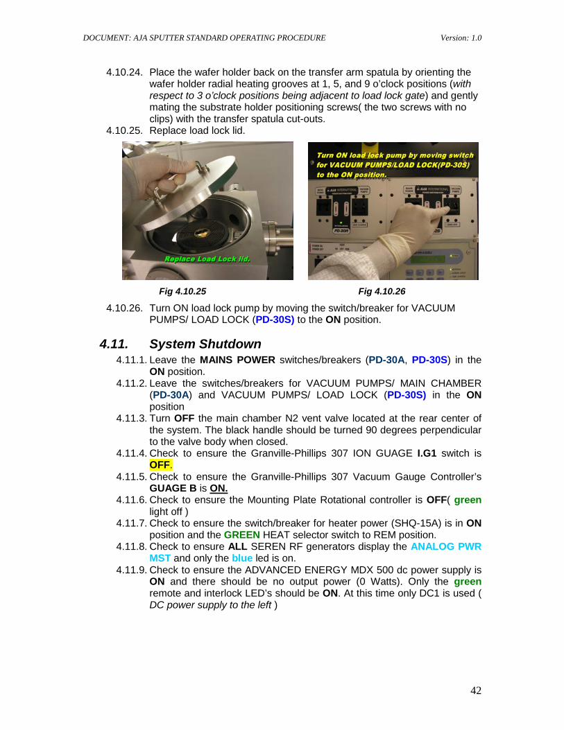
4.10.20. Remove the load lock lid and place it on the load lock / flange pad located on the AJA table top.
4.10.21. Remove the wafer holder from transfer arm spatula by gently lifting the holder straight up and placing on clean Aluminum foil.
Fig 4.10.20 Fig 4.10.21
4.10.22. Remove your wafer/samples from the wafer holding clips using a 3/32” allen wrench.
4.10.23. Inspect the wafer holder for particles and wipe clean with lint free wipes and isopropyl alcohol if needed.
Fig 4.10.22 Fig 4.10.23
DOCUMENT: AJA SPUTTER STANDARD OPERATING PROCEDURE Version: 1.0
42
4.10.24. Place the wafer holder back on the transfer arm spatula by orienting the wafer holder radial heating grooves at 1, 5, and 9 o’clock positions (with respect to 3 o’clock positions being adjacent to load lock gate) and gently mating the substrate holder positioning screws( the two screws with no clips) with the transfer spatula cut-outs.
4.10.25. Replace load lock lid.
Fig 4.10.25 Fig 4.10.26
4.10.26. Turn ON load lock pump by moving the switch/breaker for VACUUM PUMPS/ LOAD LOCK (PD-30S) to the ON position.
4.11. System Shutdown 4.11.1. Leave the MAINS POWER switches/breakers (PD-30A, PD-30S) in the
ON position. 4.11.2. Leave the switches/breakers for VACUUM PUMPS/ MAIN CHAMBER
(PD-30A) and VACUUM PUMPS/ LOAD LOCK (PD-30S) in the ON position
4.11.3. Turn OFF the main chamber N2 vent valve located at the rear center of the system. The black handle should be turned 90 degrees perpendicular to the valve body when closed.
4.11.4. Check to ensure the Granville-Phillips 307 ION GUAGE I.G1 switch is OFF.
4.11.5. Check to ensure the Granville-Phillips 307 Vacuum Gauge Controller’s GUAGE B is
4.11.6. Check to ensure the Mounting Plate Rotational controller is OFF( green light off )
ON.
4.11.7. Check to ensure the switch/breaker for heater power (SHQ-15A) is in ON position and the GREEN HEAT selector switch to REM position.
4.11.8. Check to ensure ALL SEREN RF generators display the ANALOG PWR MST and only the blue led is on.
4.11.9. Check to ensure the ADVANCED ENERGY MDX 500 dc power supply is ON and there should be no output power (0 Watts). Only the green remote and interlock LED’s should be ON. At this time only DC1 is used ( DC power supply to the left )
DOCUMENT: AJA SPUTTER STANDARD OPERATING PROCEDURE Version: 1.0
43
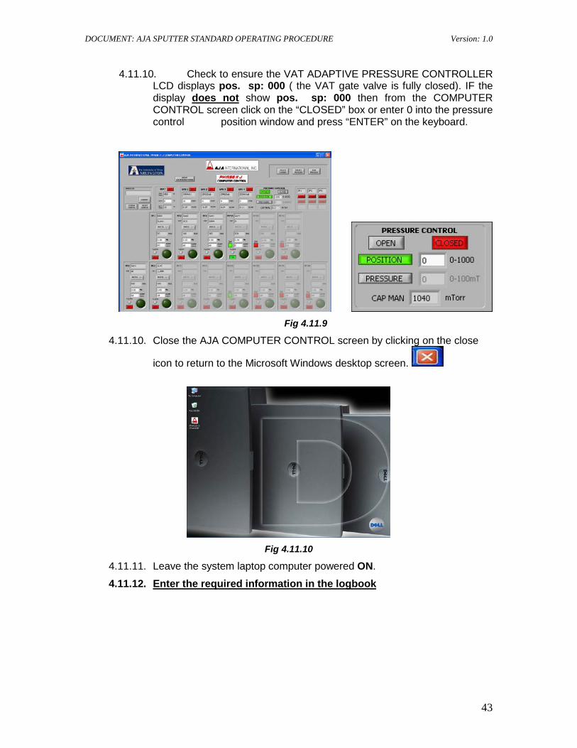
4.11.10. Check to ensure the VAT ADAPTIVE PRESSURE CONTROLLER LCD displays pos. sp: 000 ( the VAT gate valve is fully closed). IF the display does not
show pos. sp: 000 then from the COMPUTER CONTROL screen click on the “CLOSED” box or enter 0 into the pressure control position window and press “ENTER” on the keyboard.
Fig 4.11.9
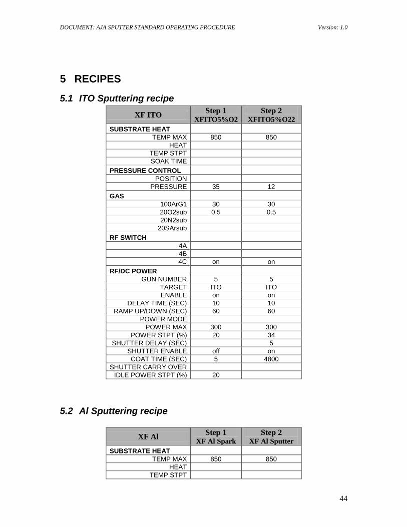
4.11.10. Close the AJA COMPUTER CONTROL screen by clicking on the close
icon to return to the Microsoft Windows desktop screen.
Fig 4.11.10
4.11.11. Leave the system laptop computer powered ON.
4.11.12.
Enter the required information in the logbook
DOCUMENT: AJA SPUTTER STANDARD OPERATING PROCEDURE Version: 1.0
44
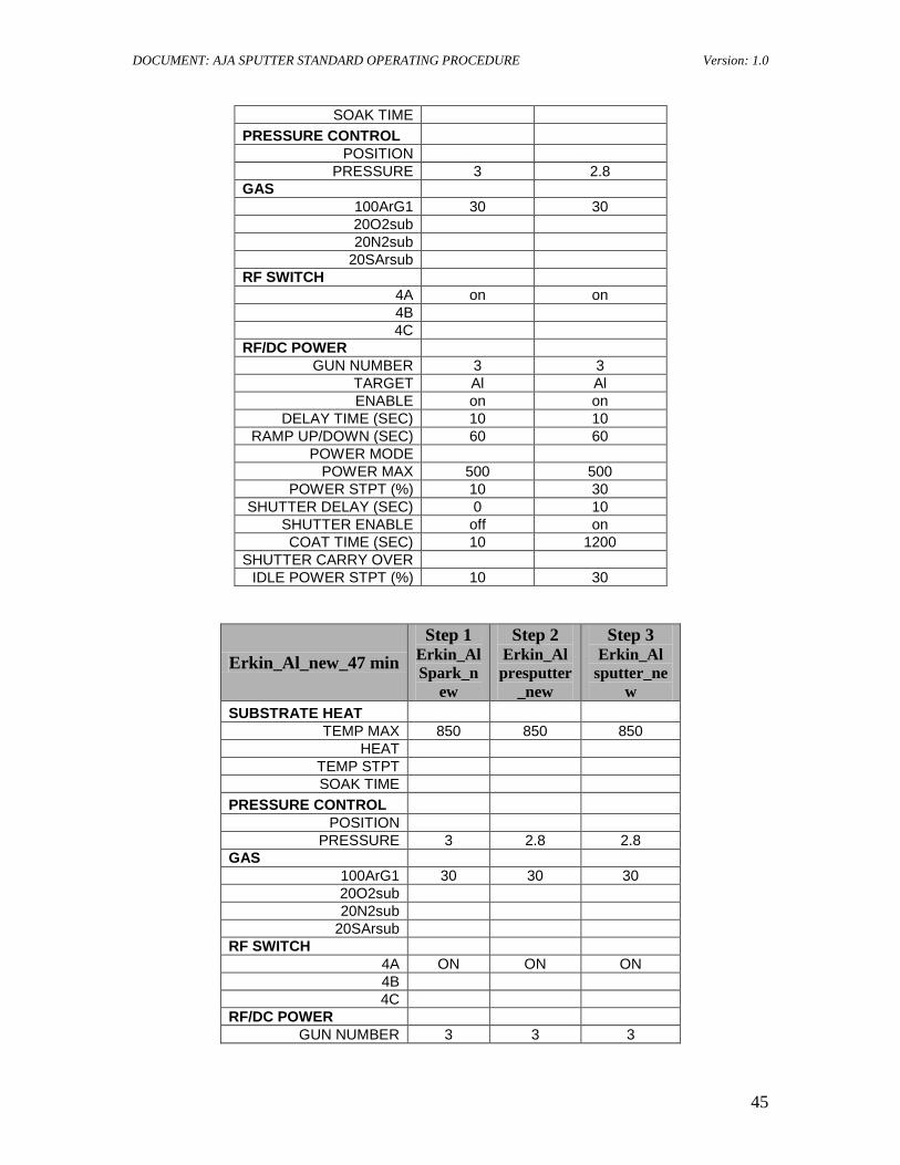
5 RECIPES
5.1 ITO Sputtering recipe XF ITO Step 1
XFITO5%O2 Step 2
XFITO5%O22 SUBSTRATE HEAT
TEMP MAX 850 850 HEAT
TEMP STPT SOAK TIME
PRESSURE CONTROL POSITION
PRESSURE 35 12 GAS
100ArG1 30 30 20O2sub 0.5 0.5 20N2sub
20SArsub RF SWITCH
4A 4B 4C on on
RF/DC POWER GUN NUMBER 5 5
TARGET ITO ITO ENABLE on on
DELAY TIME (SEC) 10 10 RAMP UP/DOWN (SEC) 60 60
POWER MODE POWER MAX 300 300
POWER STPT (%) 20 34 SHUTTER DELAY (SEC) 5
SHUTTER ENABLE off on COAT TIME (SEC) 5 4800
SHUTTER CARRY OVER IDLE POWER STPT (%) 20
5.2 Al Sputtering recipe
XF Al Step 1 XF Al Spark
Step 2 XF Al Sputter
SUBSTRATE HEAT TEMP MAX 850 850
HEAT TEMP STPT
DOCUMENT: AJA SPUTTER STANDARD OPERATING PROCEDURE Version: 1.0
45
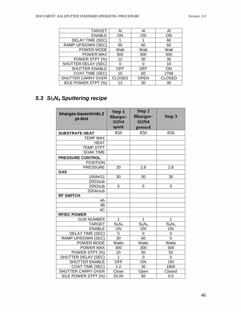
SOAK TIME PRESSURE CONTROL
POSITION PRESSURE 3 2.8
GAS 100ArG1 30 30 20O2sub 20N2sub
20SArsub RF SWITCH
4A on on 4B 4C
RF/DC POWER GUN NUMBER 3 3
TARGET Al Al ENABLE on on
DELAY TIME (SEC) 10 10 RAMP UP/DOWN (SEC) 60 60
POWER MODE POWER MAX 500 500
POWER STPT (%) 10 30 SHUTTER DELAY (SEC) 0 10
SHUTTER ENABLE off on COAT TIME (SEC) 10 1200
SHUTTER CARRY OVER IDLE POWER STPT (%) 10 30
Erkin_Al_new_47 min Step 1
Erkin_Al Spark_n
ew
Step 2 Erkin_Al presputter
_new
Step 3 Erkin_Al
sputter_new
SUBSTRATE HEAT TEMP MAX 850 850 850
HEAT TEMP STPT SOAK TIME
PRESSURE CONTROL POSITION
PRESSURE 3 2.8 2.8 GAS
100ArG1 30 30 30 20O2sub 20N2sub
20SArsub RF SWITCH
4A ON ON ON 4B 4C
RF/DC POWER GUN NUMBER 3 3 3
DOCUMENT: AJA SPUTTER STANDARD OPERATING PROCEDURE Version: 1.0
46
TARGET Al Al Al ENABLE ON ON ON
DELAY TIME (SEC) 1 1 60 RAMP UP/DOWN (SEC) 60 60 60
POWER MODE Watt Watt Watt POWER MAX 500 500 500
POWER STPT (%) 12 30 30 SHUTTER DELAY (SEC) 0 0 10
SHUTTER ENABLE OFF OFF ON COAT TIME (SEC) 10 60 2768
SHUTTER CARRY OVER CLOSED OPEN CLOSED IDLE POWER STPT (%) 12 30 30
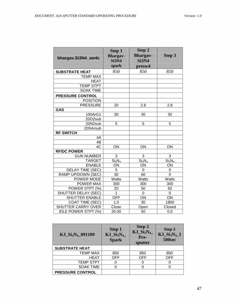
5.3 Si3N4 Sputtering recipe
bhargav.basenitride.2pt-8mt
Step 1 Bhargav-
Si3N4 spark
Step 2 Bhargav-
Si3N4 presw4
Step 3
SUBSTRATE HEAT 850 850 850 TEMP MAX
HEAT TEMP STPT SOAK TIME
PRESSURE CONTROL POSITION
PRESSURE 20 2.8 2.8 GAS
100ArG1 30 30 30 20O2sub 20N2sub 5 5 5
20SArsub RF SWITCH
4A 4B 4C
RF/DC POWER GUN NUMBER 1 1 1
TARGET Si3N4 Si3N4 Si3N4 ENABLE ON ON ON
DELAY TIME (SEC) 5 0 0 RAMP UP/DOWN (SEC) 30 60 0
POWER MODE Watts Watts Watts POWER MAX 300 300 300
POWER STPT (%) 20 50 50 SHUTTER DELAY (SEC) 1 0 0
SHUTTER ENABLE OFF ON ON COAT TIME (SEC) 1.0 30 1800
SHUTTER CARRY OVER Close Open Closed IDLE POWER STPT (%) 20.00 50 0.0
DOCUMENT: AJA SPUTTER STANDARD OPERATING PROCEDURE Version: 1.0
47
bhargav.Si3N4_sw4c Step 1
Bhargav-Si3N4 spark
Step 2 Bhargav-
Si3N4 presw4
Step 3
SUBSTRATE HEAT 850 850 850 TEMP MAX
HEAT TEMP STPT SOAK TIME
PRESSURE CONTROL POSITION
PRESSURE 20 2.8 2.8 GAS
100ArG1 30 30 30 20O2sub 20N2sub 5 5 5
20SArsub RF SWITCH
4A 4B 4C ON ON ON
RF/DC POWER GUN NUMBER 3 3 3
TARGET Si3N4 Si3N4 Si3N4 ENABLE ON ON ON
DELAY TIME (SEC) 5 0 0 RAMP UP/DOWN (SEC) 30 60 0
POWER MODE Watts Watts Watts POWER MAX 300 300 300
POWER STPT (%) 20 50 50 SHUTTER DELAY (SEC) 1 0 0
SHUTTER ENABLE OFF ON ON COAT TIME (SEC) 1.0 30 1800
SHUTTER CARRY OVER Close Open Closed IDLE POWER STPT (%) 20.00 50 0.0
KJ_Si3N4_091109 Step 1
KJ_Si3N4_ Spark
Step 2 KJ_Si3N4_
Pre-sputter
Step 3 KJ_Si3N4_1
500sec
SUBSTRATE HEAT TEMP MAX 850 850 850
HEAT OFF OFF OFF TEMP STPT 0 0 0 SOAK TIME 0 0 0
PRESSURE CONTROL
DOCUMENT: AJA SPUTTER STANDARD OPERATING PROCEDURE Version: 1.0
48
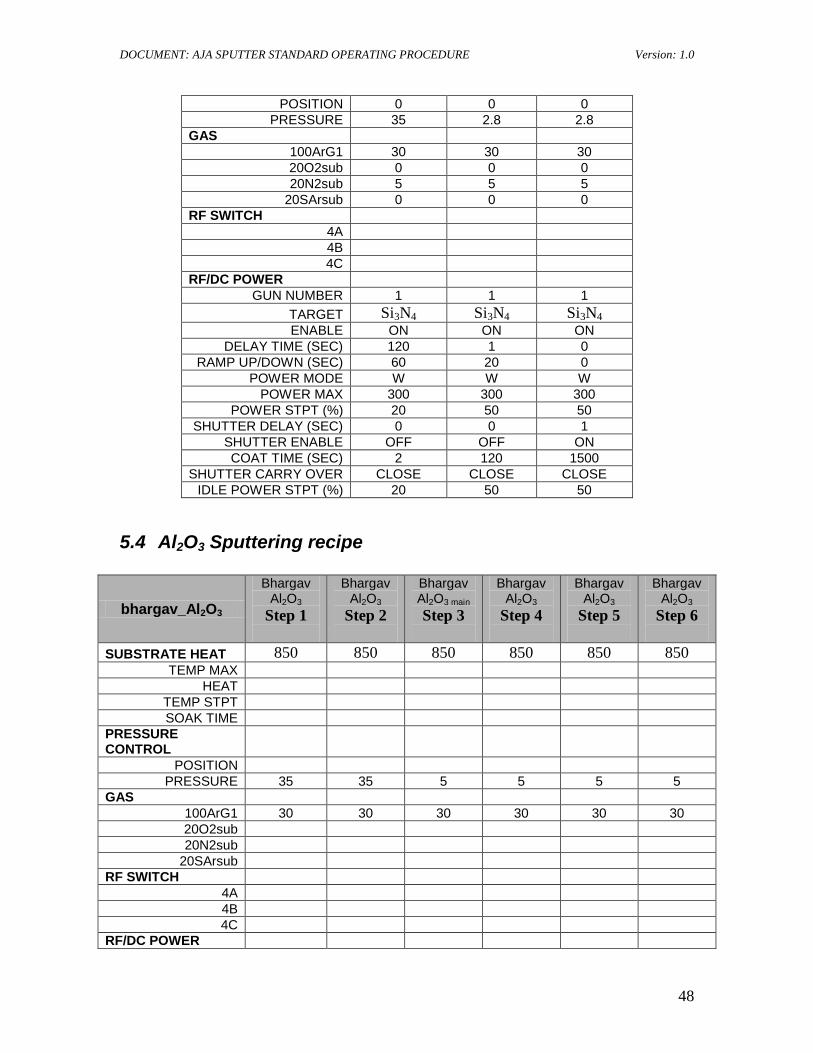
POSITION 0 0 0 PRESSURE 35 2.8 2.8
GAS 100ArG1 30 30 30 20O2sub 0 0 0 20N2sub 5 5 5
20SArsub 0 0 0 RF SWITCH
4A 4B 4C
RF/DC POWER GUN NUMBER 1 1 1
TARGET Si3N4 Si3N4 Si3N4 ENABLE ON ON ON
DELAY TIME (SEC) 120 1 0 RAMP UP/DOWN (SEC) 60 20 0
POWER MODE W W W POWER MAX 300 300 300
POWER STPT (%) 20 50 50 SHUTTER DELAY (SEC) 0 0 1
SHUTTER ENABLE OFF OFF ON COAT TIME (SEC) 2 120 1500
SHUTTER CARRY OVER CLOSE CLOSE CLOSE IDLE POWER STPT (%) 20 50 50
5.4 Al2O3 Sputtering recipe
bhargav_Al2O3 Bhargav
Al2O3
Step 1
Bhargav Al2O3
Step 2
Bhargav Al2O3 main
Step 3
Bhargav Al2O3
Step 4
Bhargav Al2O3
Step 5
Bhargav Al2O3
Step 6
SUBSTRATE HEAT 850 850 850 850 850 850 TEMP MAX
HEAT TEMP STPT SOAK TIME
PRESSURE CONTROL
POSITION PRESSURE 35 35 5 5 5 5
GAS 100ArG1 30 30 30 30 30 30 20O2sub 20N2sub
20SArsub RF SWITCH
4A 4B 4C
RF/DC POWER
DOCUMENT: AJA SPUTTER STANDARD OPERATING PROCEDURE Version: 1.0
49
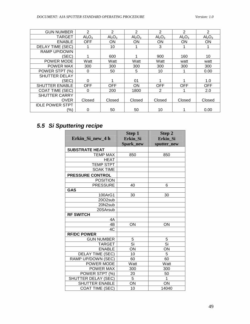
GUN NUMBER 2 2 2 2 2 2 TARGET Al2O3 Al2O3 Al2O3 Al2O3 Al2O3 Al2O3 ENABLE OFF ON ON ON ON ON
DELAY TIME (SEC) 1 10 1 3 1 1 RAMP UP/DOWN
(SEC) 1 600 1 900 160 10 POWER MODE Watt Watt Watt Watt watt watt
POWER MAX 300 300 300 300 300 300 POWER STPT (%) 0 50 5 10 1 0.00 SHUTTER DELAY
(SEC) 0 1 01 1 1 1.0 SHUTTER ENABLE OFF OFF ON OFF OFF OFF COAT TIME (SEC) 0 200 1800 2 1 2.0 SHUTTER CARRY
OVER Closed Closed Closed Closed Closed Closed IDLE POWER STPT
(%) 0 50 50 10 1 0.00
5.5 Si Sputtering recipe
Erkin_Si_new_4 h Step 1
Erkin_Si Spark_new
Step 2 Erkin_Si
sputter_new SUBSTRATE HEAT
TEMP MAX 850 850 HEAT
TEMP STPT SOAK TIME
PRESSURE CONTROL POSITION
PRESSURE 40 6 GAS
100ArG1 30 30 20O2sub 20N2sub
20SArsub RF SWITCH
4A 4B ON ON 4C
RF/DC POWER GUN NUMBER 5 5
TARGET Si Si ENABLE ON ON
DELAY TIME (SEC) 10 5 RAMP UP/DOWN (SEC) 60 60
POWER MODE Watt Watt POWER MAX 300 300
POWER STPT (%) 20 50 SHUTTER DELAY (SEC) 5 1
SHUTTER ENABLE ON ON COAT TIME (SEC) 10 14040
DOCUMENT: AJA SPUTTER STANDARD OPERATING PROCEDURE Version: 1.0
50
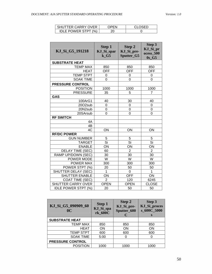
SHUTTER CARRY OVER OPEN CLOSED IDLE POWER STPT (%) 20 0
KJ_Si_G5_191218 Step 1
KJ_Si_spark_G5
Step 2 KJ_Si_pre-Sputter_G5
Step 3 KJ_Si_process_500
0s_G5 SUBSTRATE HEAT
TEMP MAX 850 850 850 HEAT OFF OFF OFF
TEMP STPT 0 0 0 SOAK TIME 0 0 0
PRESSURE CONTROL POSITION 1000 1000 1000
PRESSURE 35 5 7 GAS
100ArG1 40 30 40 20O2sub 0 0 0 20N2sub 0 0 0
20SArsub 0 0 0 RF SWITCH
4A 4B 4C ON ON ON
RF/DC POWER GUN NUMBER 5 5 5
TARGET Si Si Si ENABLE ON ON ON
DELAY TIME (SEC) 60 2 2 RAMP UP/DOWN (SEC) 30 30 30
POWER MODE W W W POWER MAX 300 300 300
POWER STPT (%) 20 50 50 SHUTTER DELAY (SEC) 1 0 1
SHUTTER ENABLE ON OFF ON COAT TIME (SEC) 2 120 6245
SHUTTER CARRY OVER OPEN OPEN CLOSE IDLE POWER STPT (%) 20 50 50
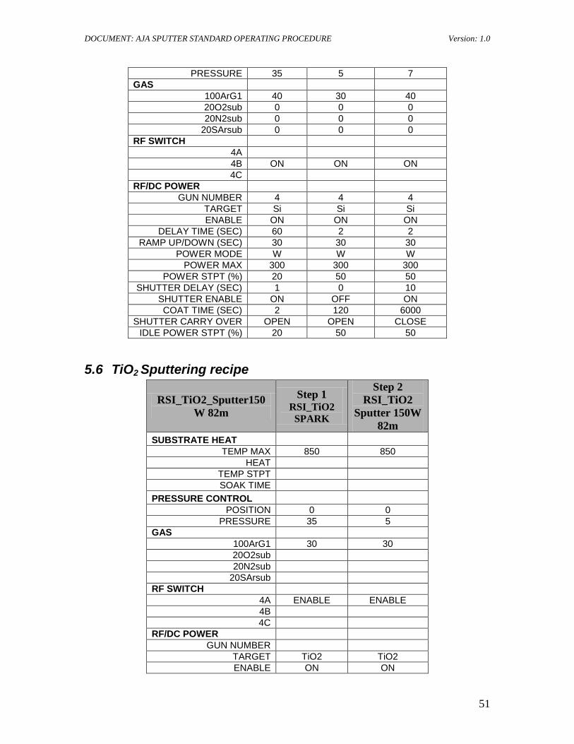
KJ_Si_G5_090909_600C
Step 1 KJ_Si_spark_600C
Step 2 KJ_Si_pre-Sputter_600
C
Step 3 KJ_Si_process_600C_5000
s SUBSTRATE HEAT
TEMP MAX 850 850 850 HEAT ON ON ON
TEMP STPT 600 600 600 SOAK TIME 5:00 0 0
PRESSURE CONTROL POSITION 1000 1000 1000
DOCUMENT: AJA SPUTTER STANDARD OPERATING PROCEDURE Version: 1.0
51
PRESSURE 35 5 7 GAS
100ArG1 40 30 40 20O2sub 0 0 0 20N2sub 0 0 0
20SArsub 0 0 0 RF SWITCH
4A 4B ON ON ON 4C
RF/DC POWER GUN NUMBER 4 4 4
TARGET Si Si Si ENABLE ON ON ON
DELAY TIME (SEC) 60 2 2 RAMP UP/DOWN (SEC) 30 30 30
POWER MODE W W W POWER MAX 300 300 300
POWER STPT (%) 20 50 50 SHUTTER DELAY (SEC) 1 0 10
SHUTTER ENABLE ON OFF ON COAT TIME (SEC) 2 120 6000
SHUTTER CARRY OVER OPEN OPEN CLOSE IDLE POWER STPT (%) 20 50 50
5.6 TiO2 Sputtering recipe
RSI_TiO2_Sputter150W 82m
Step 1 RSI_TiO2 SPARK
Step 2 RSI_TiO2
Sputter 150W 82m
SUBSTRATE HEAT TEMP MAX 850 850
HEAT TEMP STPT SOAK TIME
PRESSURE CONTROL POSITION 0 0
PRESSURE 35 5 GAS
100ArG1 30 30 20O2sub 20N2sub
20SArsub RF SWITCH
4A ENABLE ENABLE 4B 4C
RF/DC POWER GUN NUMBER
TARGET TiO2 TiO2 ENABLE ON ON
DOCUMENT: AJA SPUTTER STANDARD OPERATING PROCEDURE Version: 1.0
52
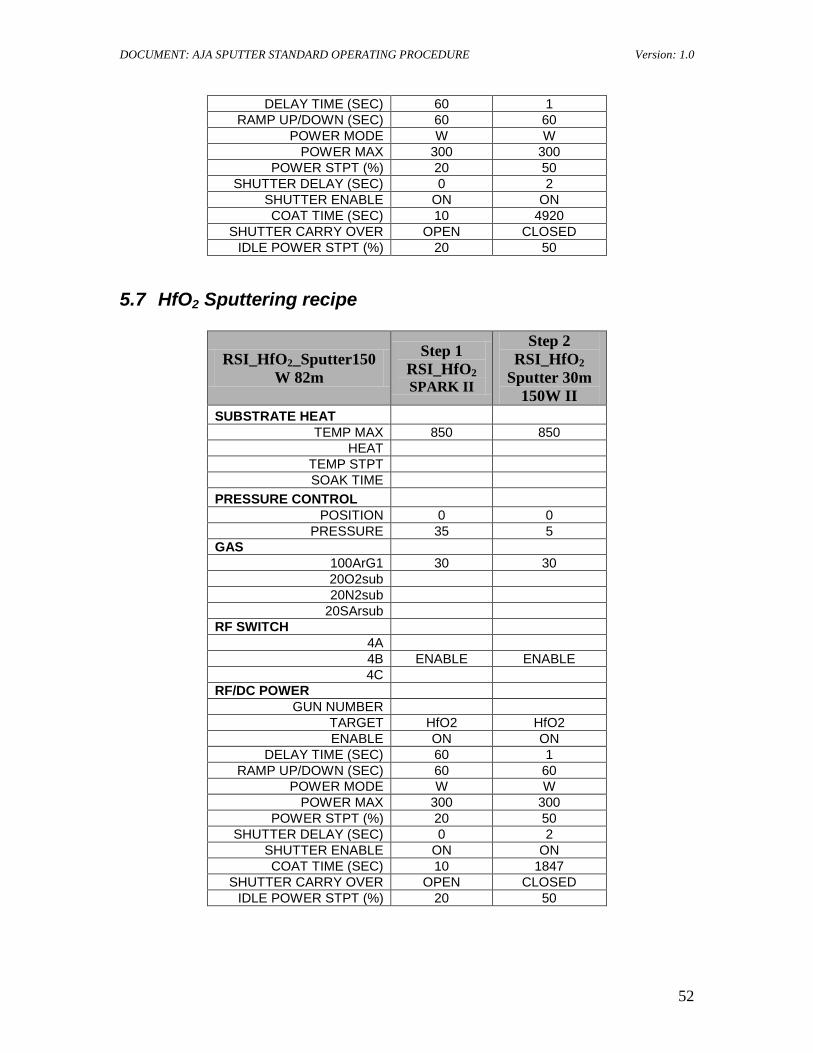
DELAY TIME (SEC) 60 1 RAMP UP/DOWN (SEC) 60 60
POWER MODE W W POWER MAX 300 300
POWER STPT (%) 20 50 SHUTTER DELAY (SEC) 0 2
SHUTTER ENABLE ON ON COAT TIME (SEC) 10 4920
SHUTTER CARRY OVER OPEN CLOSED IDLE POWER STPT (%) 20 50
5.7 HfO2 Sputtering recipe
RSI_HfO2_Sputter150W 82m
Step 1 RSI_HfO2 SPARK II
Step 2 RSI_HfO2
Sputter 30m 150W II
SUBSTRATE HEAT TEMP MAX 850 850
HEAT TEMP STPT SOAK TIME
PRESSURE CONTROL POSITION 0 0
PRESSURE 35 5 GAS
100ArG1 30 30 20O2sub 20N2sub
20SArsub RF SWITCH
4A 4B ENABLE ENABLE 4C
RF/DC POWER GUN NUMBER
TARGET HfO2 HfO2 ENABLE ON ON
DELAY TIME (SEC) 60 1 RAMP UP/DOWN (SEC) 60 60
POWER MODE W W POWER MAX 300 300
POWER STPT (%) 20 50 SHUTTER DELAY (SEC) 0 2
SHUTTER ENABLE ON ON COAT TIME (SEC) 10 1847
SHUTTER CARRY OVER OPEN CLOSED IDLE POWER STPT (%) 20 50