AJ Laser 230z Assembly Instructions - RC DEPOT · 93” AJ Laser 230z Assembly Instructions....
27
93” AJ Laser 230z Assembly Instructions
-
Upload
hoangkhanh -
Category
Documents
-
view
214 -
download
0
Transcript of AJ Laser 230z Assembly Instructions - RC DEPOT · 93” AJ Laser 230z Assembly Instructions....
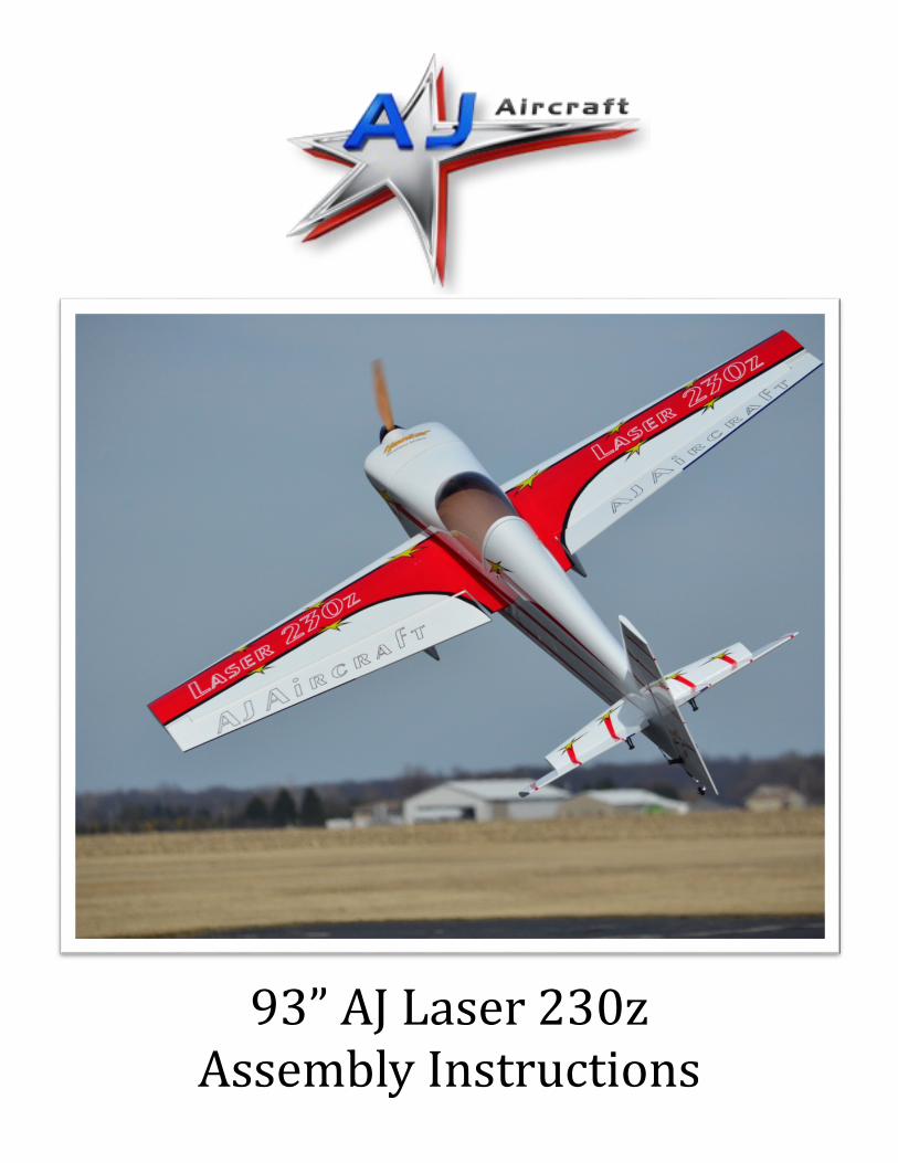
93” AJ Laser 230z Assembly Instructions
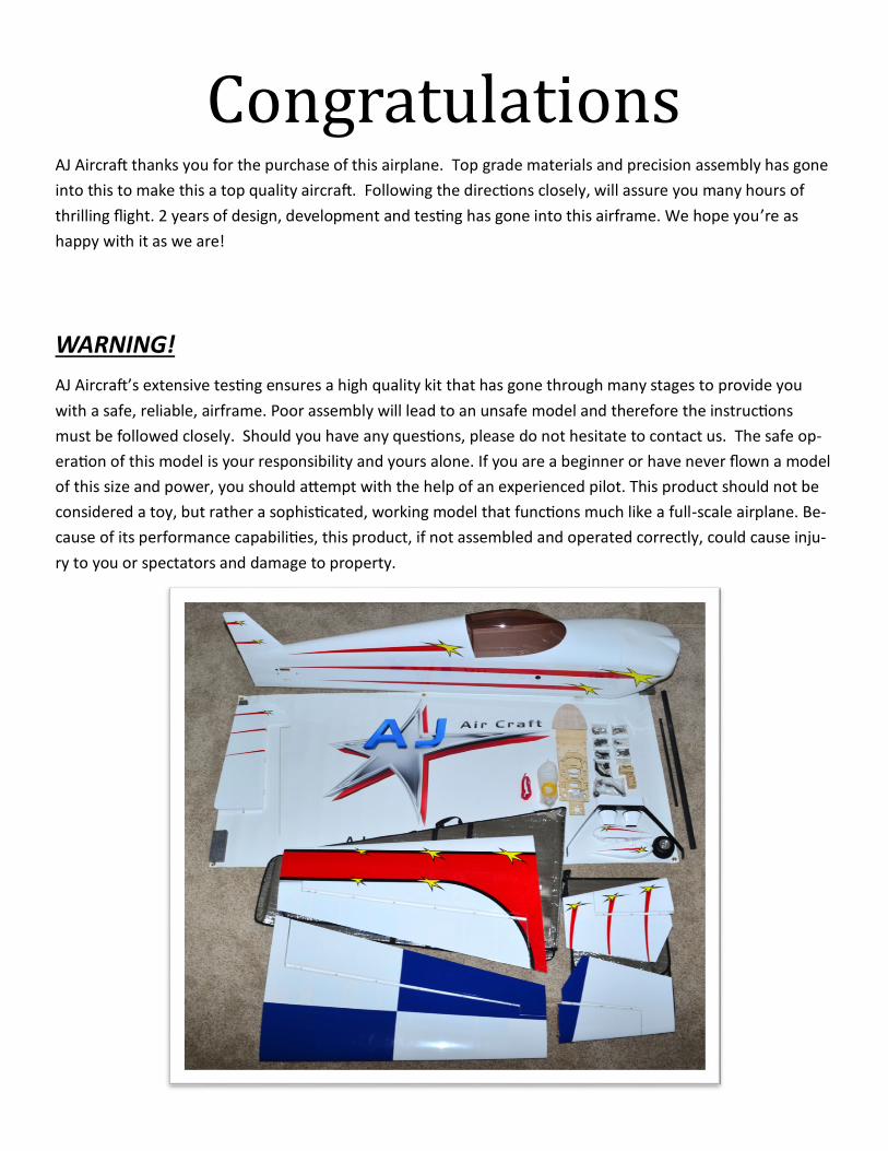
Congratulations AJ Aircraft thanks you for the purchase of this airplane. Top grade materials and precision assembly has gone
into this to make this a top quality aircraft. Following the directions closely, will assure you many hours of
thrilling flight. 2 years of design, development and testing has gone into this airframe. We hope you’re as
happy with it as we are!
WARNING!
AJ Aircraft’s extensive testing ensures a high quality kit that has gone through many stages to provide you
with a safe, reliable, airframe. Poor assembly will lead to an unsafe model and therefore the instructions
must be followed closely. Should you have any questions, please do not hesitate to contact us. The safe op-
eration of this model is your responsibility and yours alone. If you are a beginner or have never flown a model
of this size and power, you should attempt with the help of an experienced pilot. This product should not be
considered a toy, but rather a sophisticated, working model that functions much like a full-scale airplane. Be-
cause of its performance capabilities, this product, if not assembled and operated correctly, could cause inju-
ry to you or spectators and damage to property.

Components
5x 300-oz minimum High Torque Metal Geared servos (400-oz minimum highly recommended for ailerons due to their size) (Futaba S-9157 are recommended)
1 standard case size servo (for gas throttle)
Heavy Duty Aluminum Servo Arms:
2x 1 3/4" for elevators
2x 1.5” for ailerons
1x 3 1/2" for rudder (or 1 3/4” if putting servo in the tail)
Servo Extensions:
2x 6" extension for ailerons (not needed for S-9157)
2x 4-6" extensions from the receiver to the ailerons
2x 48" extensions for the elevators
1x 12" extension for the ESC to Receiver (if electric)
2x 12" extension will be needed for the throttle servo and ignition (if gas)
4” / 100mm Spinner
60-70cc Gas Engine (DA-70 recommended) or Hacker Q-80M or equivalent electric motor
Castle 160a ESC or equivalent (for electric)
24x10 or similar Prop (Falcon recommended)
5 channel receiver
Flight or receiver/ignition batteries
Powerbox smart switch Ignition cut-off (if gas)
Tools
I. Blue Painters Masking Tape
II. Denatured Alcohol & Paper Towels
III. Blue Loctite
IV. Metric & Standard Allen Wrenches
V. Hobby Knife & Fresh Blades
VI. Thirty Minute Epoxy (or Gorilla Glue)
VII. Fifteen Minute Epoxy
VIII.Thin C/A
VI. Electric Drill w/ Assorted Small Bits
VII. Small Flat & Phillips Screwdrivers
VIII.Sanding Block & Sandpaper
IX. Needle Nose Pliers
X. Measuring Tape & Ruler
XI. Fine-tip Sharpie Marker
Recommended Items
For Completion

Tips for Success Before starting, read through the entire set of instructions to familiarize yourself with the process.
Take a few minutes to go over all of the covering, especially the seams and decals, with a covering iron on
low to medium heat. You may want to use a drop of clear nail polish on the tips of stars to keep them
from lifting.
Inspect for any interior joints that may have loosened as a result of shipping & handling, and apply a cou-
ple drops of thin CA.
Pre-center your servos before installing using a servo tester, or by plugging them into your powered re-
ceiver.
ALL METAL BOLTS should get a drop of blue Locktite, even when using nylon lock-nuts.
Do your best to mechanically center all flying surfaces, so little to no sub-trim will be required in the radio
setup. Use a piece of tape to hold your surfaces level and thread the ball links in or out until it’s perfect.
Take the time to properly balance and trim your aircraft.
Use the suggested throws at the end of this manual as your starting point, and then fine tune to your fly-
ing preferences after your first few flights.
You may notice that some pictures in this manual may be of a different size Laser. In this case, the differ-
ences did not make a difference in explaining that part of the build.
If there’s ever a question, post on an RC forum or contact AJ Aircraft to verify before doing anything.
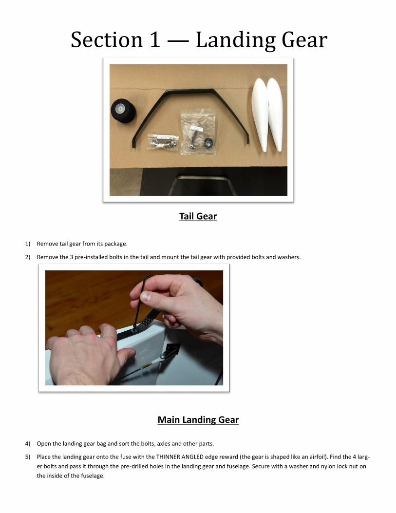
Tail Gear
1) Remove tail gear from its package.
2) Remove the 3 pre-installed bolts in the tail and mount the tail gear with provided bolts and washers.
Main Landing Gear
4) Open the landing gear bag and sort the bolts, axles and other parts.
5) Place the landing gear onto the fuse with the THINNER ANGLED edge reward (the gear is shaped like an airfoil). Find the 4 larg-
er bolts and pass it through the pre-drilled holes in the landing gear and fuselage. Secure with a washer and nylon lock nut on
the inside of the fuselage.
Section 1 — Landing Gear
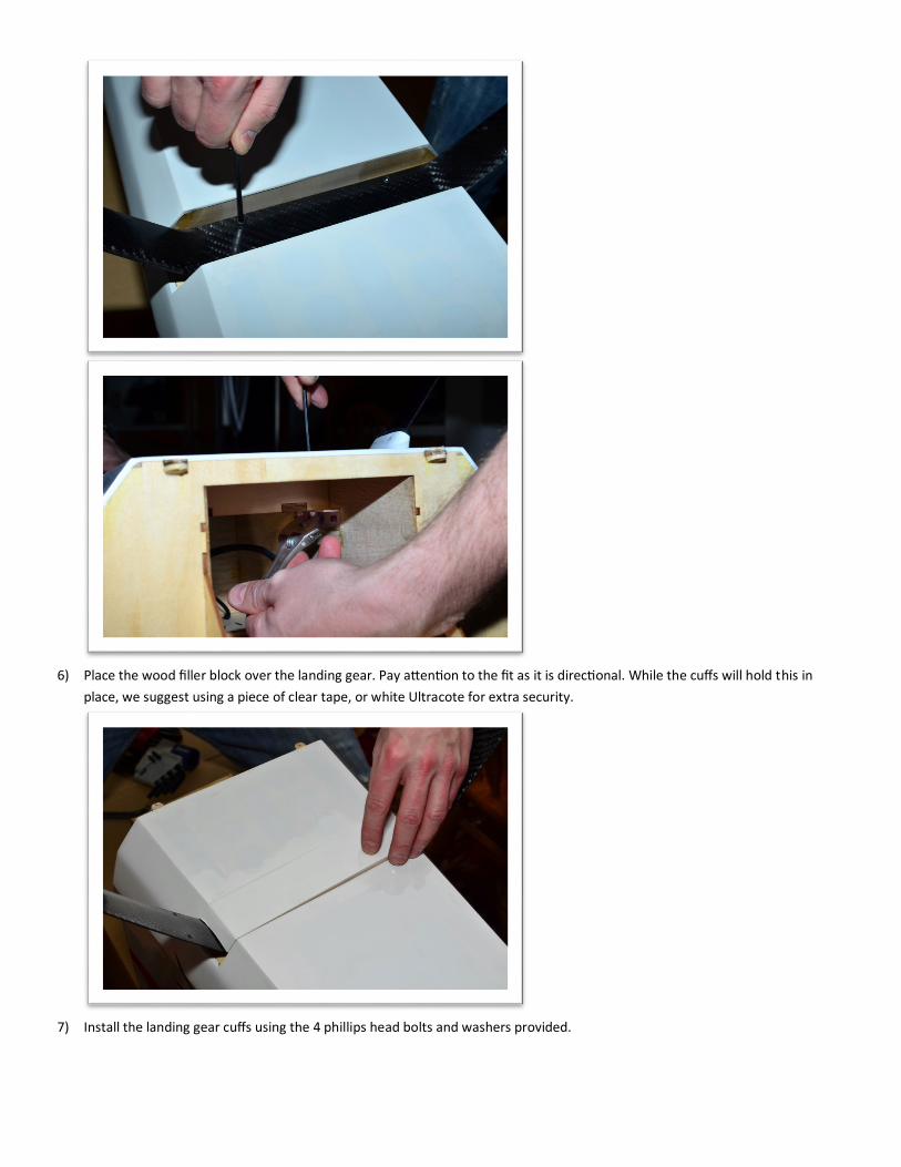
6) Place the wood filler block over the landing gear. Pay attention to the fit as it is directional. While the cuffs will hold this in
place, we suggest using a piece of clear tape, or white Ultracote for extra security.
7) Install the landing gear cuffs using the 4 phillips head bolts and washers provided.
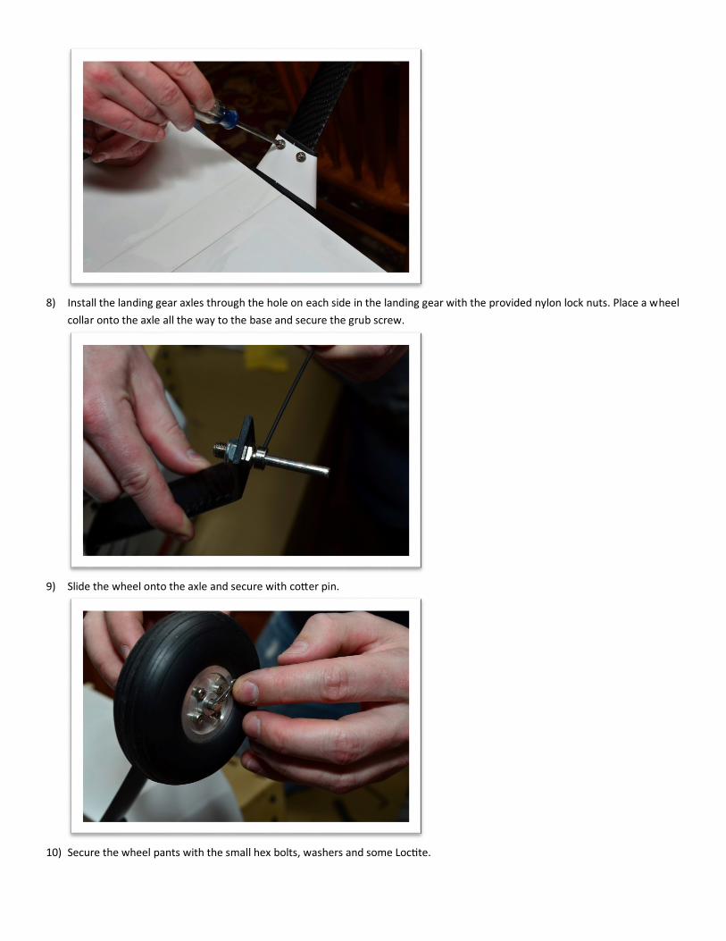
8) Install the landing gear axles through the hole on each side in the landing gear with the provided nylon lock nuts. Place a wheel
collar onto the axle all the way to the base and secure the grub screw.
9) Slide the wheel onto the axle and secure with cotter pin.
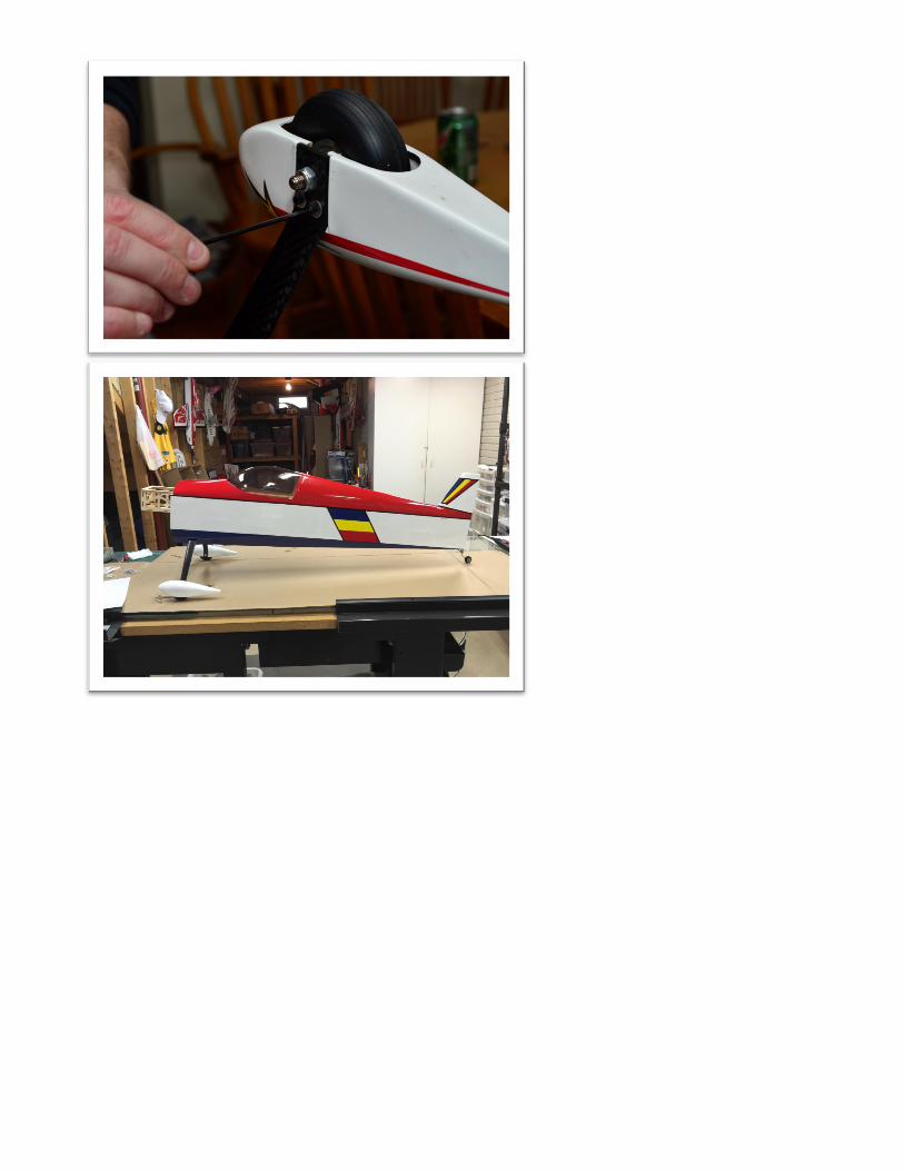
10) Secure the wheel pants with the small hex bolts, washers and some Loctite.

Section 2 — Elevator/Rudder
11) Remove the horizontal stabs, elevators, control horns and ball link hardware.
12) Use a sharp blade to cut the 2 slots on each elevator half. Check to make sure you are cutting the
BOTTOM of the elevator. The cut doesn’t have to be perfect, as we will be removing covering around
this coming up.
13) Assemble the horn in the order of bolt, washer, control horn, ball link, control horn, washer, lock nut.
Take note to use the ball link that does not have the extra half-sphere here. The other ball-links are
used on the servo arm end.

14) Test fit the control horns into their slots in each elevator half to make sure they will fully seat down. Sand
the corners or bottom edge if necessary. Trace around the base plate with a fine Sharpie.
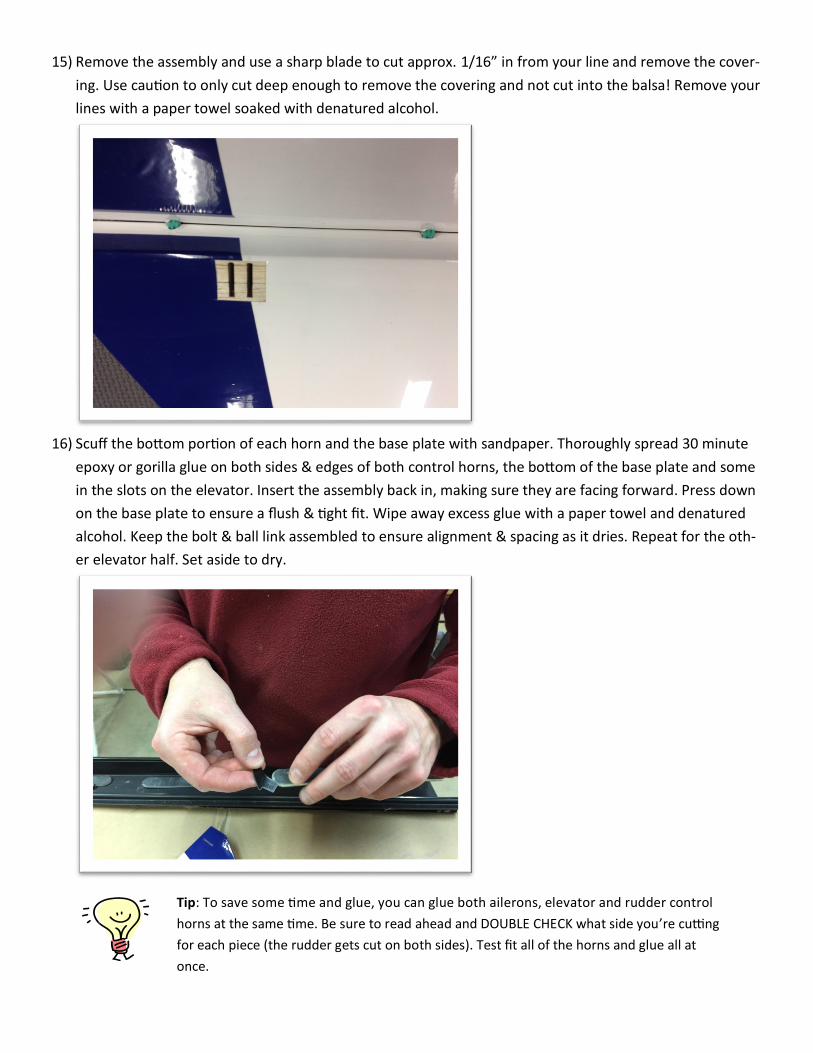
15) Remove the assembly and use a sharp blade to cut approx. 1/16” in from your line and remove the cover-
ing. Use caution to only cut deep enough to remove the covering and not cut into the balsa! Remove your
lines with a paper towel soaked with denatured alcohol.
16) Scuff the bottom portion of each horn and the base plate with sandpaper. Thoroughly spread 30 minute
epoxy or gorilla glue on both sides & edges of both control horns, the bottom of the base plate and some
in the slots on the elevator. Insert the assembly back in, making sure they are facing forward. Press down
on the base plate to ensure a flush & tight fit. Wipe away excess glue with a paper towel and denatured
alcohol. Keep the bolt & ball link assembled to ensure alignment & spacing as it dries. Repeat for the oth-
er elevator half. Set aside to dry.
Tip: To save some time and glue, you can glue both ailerons, elevator and rudder control
horns at the same time. Be sure to read ahead and DOUBLE CHECK what side you’re cutting
for each piece (the rudder gets cut on both sides). Test fit all of the horns and glue all at
once.
17) Seal the hinge gaps with strips of Ultracote or Blenderm tape. Make sure the surface is fully deflected
when applying the seal strip. Sealing the gap will ensure the airflow continues over the elevator instead of
going through the hinge gap.
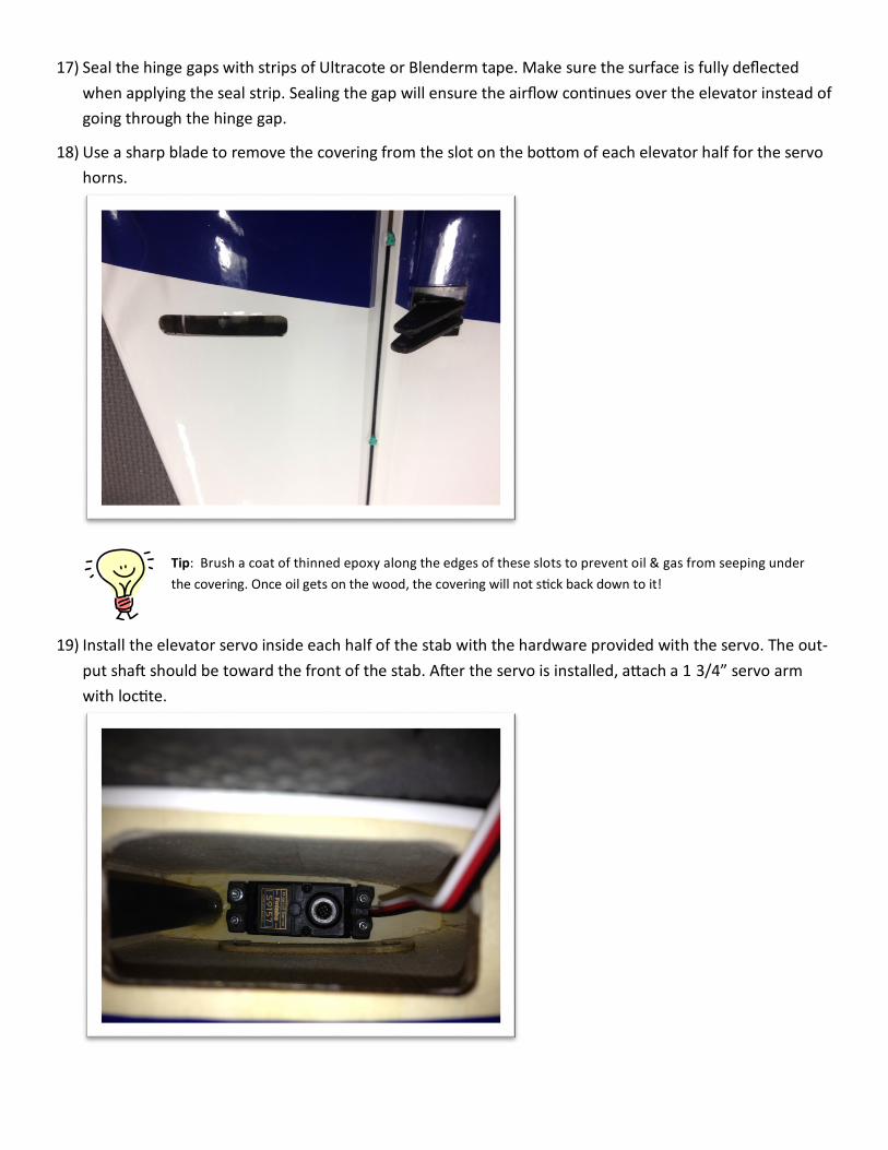
18) Use a sharp blade to remove the covering from the slot on the bottom of each elevator half for the servo
horns.
19) Install the elevator servo inside each half of the stab with the hardware provided with the servo. The out-
put shaft should be toward the front of the stab. After the servo is installed, attach a 1 3/4” servo arm
with loctite.
Tip: Brush a coat of thinned epoxy along the edges of these slots to prevent oil & gas from seeping under
the covering. Once oil gets on the wood, the covering will not stick back down to it!
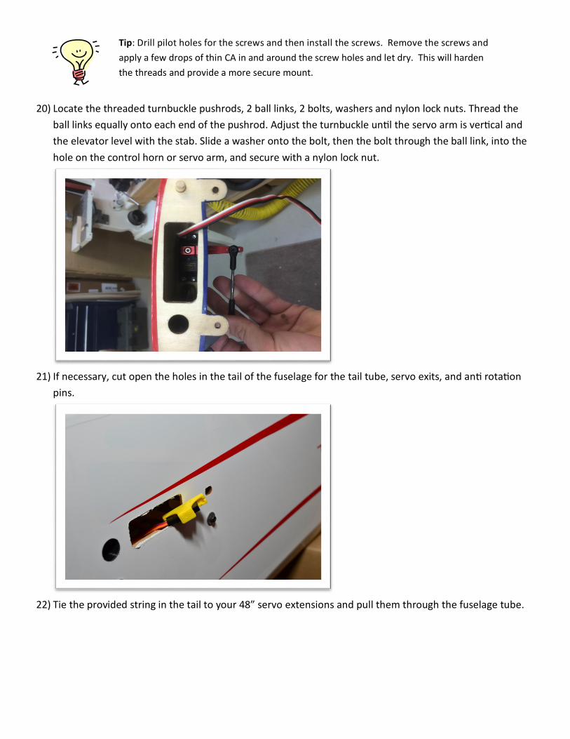
20) Locate the threaded turnbuckle pushrods, 2 ball links, 2 bolts, washers and nylon lock nuts. Thread the
ball links equally onto each end of the pushrod. Adjust the turnbuckle until the servo arm is vertical and
the elevator level with the stab. Slide a washer onto the bolt, then the bolt through the ball link, into the
hole on the control horn or servo arm, and secure with a nylon lock nut.
21) If necessary, cut open the holes in the tail of the fuselage for the tail tube, servo exits, and anti rotation
pins.
22) Tie the provided string in the tail to your 48” servo extensions and pull them through the fuselage tube.
Tip: Drill pilot holes for the screws and then install the screws. Remove the screws and
apply a few drops of thin CA in and around the screw holes and let dry. This will harden
the threads and provide a more secure mount.

23) Slide in the small carbon fiber tube into the tail and connect the servos to their extensions. Always use a
servo keeper on these! Slide each elevator half onto the tube, tucking the extra servo wire into the fuse.
24) Secure the stabs with the provided bolts and washers. Be sure to check these bolts after every flight!

25) Begin by inspecting the airframe and applying thin CA to any joints that may have loosened during shipping & handling. Also
take time now to run your covering iron over all seams and decals, if you haven't already. Once completed, you can open the
holes needed on each side for the front & back anti-rotation pins, wing bolts and servo wire access holes.
26) Now let’s get some power under the hood. The firewall center lines have been pre-scribed for you. Drill templates have been
provided if you’re using the DA-60, DA-70 or 3W-50. Otherwise, use the manufacturers mounting template and tape it to the
engine box, lining up the vertical line on the template with the RIGHT vertical line on the firewall. Drill the 4 mounting holes
using the drill bit size by your engine/motor manufacturer (typically 1/4”). Also mark and open the other holes and slots in the
template for the throttle pushrod, fuel line, etc.
Going Electric? Skip ahead. Going Gas? Read on!
27) Temporarily mount the included firewall standoffs (or standoffs that will take your prop backplate to a distance of 6 5/8” from
the firewall) using your engine’s recommended bolts, washers and nylon lock nuts to check for clearance on the carburetor.
You may find it necessary to remove some wood around the hole in the firewall to clear the carb. If so, a dremel sanding drum
makes quick work of this. You can also use this opportunity to mark the location of your throttle arm on the carb and fuel line
locations on to the firewall and/or motor box sides (if not already done via the template). Use a dremel or drill an elongated
slot to accommodate the full travel of the throttle.
28) If you plan on using a tuned pipe, use the provided pipe mount options and cut open the vent hole behind the landing gear.
Section 3 — Fuselage

29) You can now re-mount your engine, mufflers and ignition box. The ignition box can be placed anywhere, but typically goes on
the top or side of the motor box. In our example, it’s been mounted to the firebox access hatch on the top of the motor box.
Don’t forget to locktite everything!
30) There’s a pre-cut hole in the bottom of the firebox for the throttle servo, which should work perfectly for the majority of gas
engines. If your engines’ throttle is in a different spot, you can use the provided ply servo mount box to locate your throttle
servo where it works best. Install the servo using the manufacturers hardware, and then make a pushrod to connect the servo
to your engine. Use the provided ball link hardware in the gas engine parts bag. Note the actual pushrod is not provided due to
the variety of engines available.

31) Assemble and install the gas tank provided and mount it in front of the wing tube. We suggest placing the provided piece of
foam under the tank to prevent foaming from vibration. Secure the tank using the provided Velcro straps running through the
slots on the plywood tray.
32) If using stock mufflers, block off the pipe tunnel by securing the provided plywood pipe tunnel isolation plate. You may need to
trim a 1/4” or so off the bottom if you find it interferes with the cowl mounting ring.
33) Cut the cowl as needed to clear the mufflers as well as extra for exiting air. No cuts should be required to clear the DA-70
heads and spark plugs. Add baffling with balsa or craft foam as desired to direct airflow over the engine heads and out the exit
in order to keep your engine running cool & happy. Baffling is not required, but is always a good idea.

Electric Motor Install
34) If using the recommended Hacker Q-80, you’ll need 3” standoffs to bring the motor forward into the cowl. If using another
motor, you’ll need standoffs that bring your spinner backplate 6 5/8” from the firewall to clear the cowl. Mount your standoffs
to the firewall. We recommend using large washers on both sides of the firewall and nylon lock nuts instead of blind nuts.
35) Mount the motor to the standoffs using the hardware provided by the motors’ manufacturer. Don’t forget to use blue locktite
on all bolts!

36) Mount your ESC to either side of the motor box with the provided Velcro through the slots on either side of the motor box.
37) Cut a hole in the main former for the power wires of the ESC to get through into the fuselage.
38) Connect your motor and ESC via bullet connectors or directly soldering the wires together. Temporarily connect the 3 wires
and power it all up to a receiver and verify the direction of rotation. If it’s the wrong way, switch 2 of the 3 wires and insulate
all wires with heat-shrink.
39) Apply at least 2 lengths of the provided Velcro on the plywood tray in the fuse forward of the wing tube. Thread in long Velcro
straps through the slots in the tray to further secure your battery packs.
Fuselage assembly continues…
40) Add some silicone glue (Zap Goop or similar) around the cowl mounting ring and the cowl on the forward side only for extra
strength. Slide the cowl into position and secure with the 3 washers and bolts through the F1 former. Note the location of the
2 tabs on the bottom of the fuse and drill through the cowl into the tabs using a small bit. Secure with the 2 wood screws
provided. You can also insert a small blind nut into the tab and use machine bolts here.
41) Install your prop and 4”/100mm spinner. Did you remember to balance them both?

42) You now have the option to use either pull-pull wires or push-pull on the rudder. Rudder pull-pull wires have been pre-strung
through the fuselage for you. In our experience if using the DA-70 on this airframe, the push-pull setup with the rudder in the
tail worked best for obtaining correct CG.
43) This model is equipped with a removable rudder for transportation and storage. Align the hinges of the rudder and the vertical
stab together. Gently slide hinge pin down from the top until the bend is in the recess on the top of the rudder. Secure with a
simple piece of tape. Note: The pin can be difficult to install. Be careful not to bend while installing. Grinding the tip to a point
and using a little dry lubrication can help.
44) Scuff the center of both control horns on both sides, and one side of each baseplate with sandpaper. Cut open the slots on
both sides of the rudder for the control horns and test fit the horns through the base plates and rudder. You may need to
slightly round the outer corners of the horns to get it all of the way through. Slide the baseplate on and mark around it.
Remove the plate and cut inside the line to remove the covering just as you did for the elevators.
45) Slide on one of the base plates, and assemble the bolt, washers, ball-link and nylon nut onto that side of the control horns to
maintain their spacing. Rotate the horns partially out and spread some glue on both sides of both horns near the center. Then,
rotate the horns back to center position. Measure each side and view from the top to make sure they are centered and
perfectly square with the fuse. Apply glue to the bottom of each baseplate and press onto the rudder. Clean up any excess glue
with an alcohol rag and then use some painters tape to hold the baseplates tight to the rudder until it dries.
Push-Pull Rudder Setup
46) If using push-pull, you will need to cut open the covering on either side of the fuse directly below the stab tube hole.
47) Mount the servo with the output shaft towards the tail and a 1 3/4” servo arm. Use the supplied turnbuckle and ball-link
hardware to connect the servo to the rudder using the same process as the elevators. Locktite all bolts.

Pull-Pull Rudder Setup
48. Install the rudder servo into the tray in the fuselage using the manufacturers’ hardware. Then attach a 3 1/2” double arm to
the servo.
49. Secure the ball link hardware to each side of the servo arm.
50. Thread the pull-pull fitting into each of the ball links about half way in.
51. Slide an aluminum crimp tube onto the end of one of the wires, and then loop the wire through the pull-pull fitting, through
the crimp tube the other way, and then loop it into the crimp tube a second time. Crimp at least twice with a crimper tool or
side cutters. Be careful not to actually cut the tube or wire by using too much force with side cutters!

52. Thread another pull-pull fitting into a ball-link and temporarily bolt it to the rudder control horn.
53. Slide an aluminum crimp tube onto the other end of the wire and thread it into the keeper and back around exactly as you did
for the servo end. Do not crimp yet!
54. Secure the rudder by lightly taping it to the vertical stab.
55. Make sure your servo is electronically centered. You’ll want to have the servo powered via a servo tester or the receiver until
the pull-pull assemblies are completed to ensure accuracy.
56. Pull on the pull-pull wire before the crimp tube to take up any slack, and adjust the loops through the fitting and crimp until
most of the slack is removed. Crimp the tube and cut off any excess wire.
57. Remove the bolt holding the ball-link and twist the pull-pull fitting in a few turns at a time and re-mount it to the horn. Adjust
in or out until the wire becomes taut. Guitar string tightness is not required, just enough to remove any slack. Secure the ball-
link with washers and a nylon lock-nut and Locktite. Repeat with the other side.
The pull-pull wires should cross in the fuselage. If you started with the left side of the servo,
the other end should attach to the right side of the rudder. If you crimped the wrong wire,
simply move the linkage to the other side of the servo before continuing.

Fuselage assembly continues…
58) Slide the large carbon fiber wing tube into the fuse and then each wing half onto the tube, pulling the aileron servo wire ends
through the hole in the fuselage. Secure the wing halves with the provided nylon thumb screws.
59) Install your switches, batteries and receiver inside the fuselage. You’ll need to assemble the plane and check your CG to
determine the best spots to mount each of these. If you’re using a tuned pipe, you will need to move things more forward. If
you’re going electric, chose a temporary spot to mount your receiver and then strap your batteries in before checking your CG.
Slide the packs forward or back to get a neutral or slightly nose heavy CG and mark the location on the ply tray for future
reference.
60) The canopy is attached to the fuselage using 2 nylon thumb screws. Do not use Loctite. Check these bolts after every flight. You
can choose to place an o-ring behind the bolt for extra security.

Section 3 — Wings
61) Assemble the control horns and ball-link the same as you did the elevators. Cut the slots in the bottom of each ailerons, test fit
the control horns, mark around the baseplate and cut away the covering. Glue in the horns exactly as you’ve done previously.
62) Utilizing a fresh blade, carefully cut and remove the covering exposing the servo mount located on the underside of each wing
panel. Apply some thin CA to all accessible joints of the servo mount and ribs.
63) Attach 6 inch servo extensions onto the servo leads and secure with heat shrink or string. Using the string inside the wing, tape
the extension to the string and pull the extension through the wing.
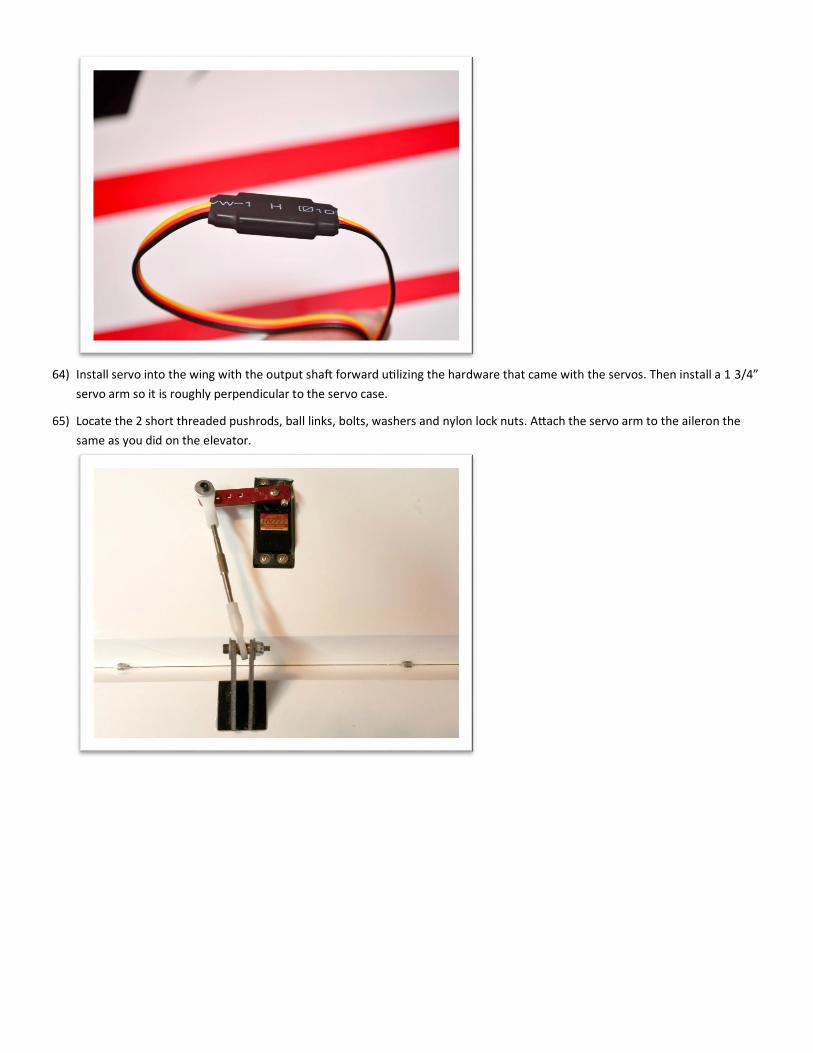
64) Install servo into the wing with the output shaft forward utilizing the hardware that came with the servos. Then install a 1 3/4”
servo arm so it is roughly perpendicular to the servo case.
65) Locate the 2 short threaded pushrods, ball links, bolts, washers and nylon lock nuts. Attach the servo arm to the aileron the
same as you did on the elevator.
Section 5
Radio Installation & Setup Your receiver can be mounted anywhere in the airframe. If not doing pull-pull rudder, the rear end of the ply tray or right behind
the wing tube is an excellent location.
While the final setup is of personal preference, these are some general guidelines to make your first flight a success.
Control Throws:
Low Rates:
A. Elevator : 15 degrees, 30% Expo
B. Aileron : 20 degrees, 30% Expo
C. Rudder : 25 degrees, 30% Expo
High Rates:
A. Elevator : 45+ degrees, 50% Expo
B. Aileron : 45+ degrees, 50% Expo
C. Rudder : 45+ degrees, 50% Expo
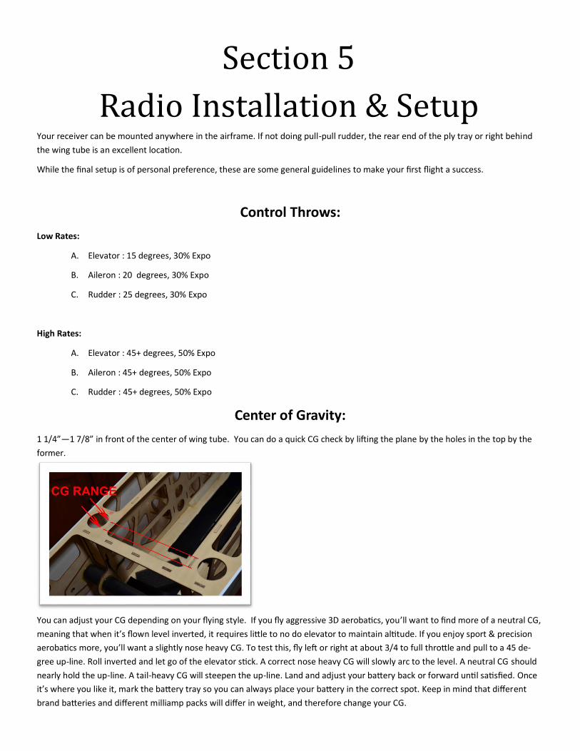
Center of Gravity:
1 1/4”—1 7/8” in front of the center of wing tube. You can do a quick CG check by lifting the plane by the holes in the top by the
former.
You can adjust your CG depending on your flying style. If you fly aggressive 3D aerobatics, you’ll want to find more of a neutral CG,
meaning that when it’s flown level inverted, it requires little to no do elevator to maintain altitude. If you enjoy sport & precision
aerobatics more, you’ll want a slightly nose heavy CG. To test this, fly left or right at about 3/4 to full throttle and pull to a 45 de-
gree up-line. Roll inverted and let go of the elevator stick. A correct nose heavy CG will slowly arc to the level. A neutral CG should
nearly hold the up-line. A tail-heavy CG will steepen the up-line. Land and adjust your battery back or forward until satisfied. Once
it’s where you like it, mark the battery tray so you can always place your battery in the correct spot. Keep in mind that different
brand batteries and different milliamp packs will differ in weight, and therefore change your CG.
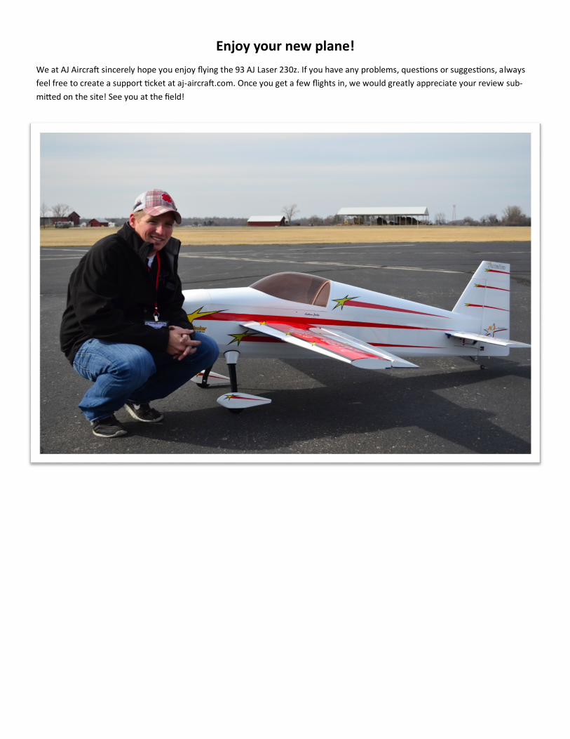
Enjoy your new plane!
We at AJ Aircraft sincerely hope you enjoy flying the 93 AJ Laser 230z. If you have any problems, questions or suggestions, always
feel free to create a support ticket at aj-aircraft.com. Once you get a few flights in, we would greatly appreciate your review sub-
mitted on the site! See you at the field!