AIX Communications Programming...
432
Bull AIX Communications Programming Concepts AIX 86 A2 35JX 01 ORDER REFERENCE
Transcript of AIX Communications Programming...
Bull AIX Communications
Programming Concepts
AIX
86 A2 35JX 01
ORDER REFERENCE


Bull AIX Communications
Programming Concepts
AIX
Software
December 1998
BULL ELECTRONICS ANGERS
CEDOC
34 Rue du Nid de Pie – BP 428
49004 ANGERS CEDEX 01
FRANCE
86 A2 35JX 01
ORDER REFERENCE

The following copyright notice protects this book under the Copyright laws of the United States of America
and other countries which prohibit such actions as, but not limited to, copying, distributing, modifying, and
making derivative works.
Copyright Bull S.A. 1992, 1998
Printed in France
Suggestions and criticisms concerning the form, content, and presentation of
this book are invited. A form is provided at the end of this book for this purpose.
To order additional copies of this book or other Bull Technical Publications, you
are invited to use the Ordering Form also provided at the end of this book.
Trademarks and Acknowledgements
We acknowledge the right of proprietors of trademarks mentioned in this book.
AIX� is a registered trademark of International Business Machines Corporation, and is being used under
licence.
UNIX is a registered trademark in the United States of America and other countries licensed exclusively
through the Open Group.
The information in this document is subject to change without notice. Groupe Bull will not be liable for errors
contained herein, or for incidental or consequential damages in connection with the use of this material.
Preface iii
About This Book
This book contains conceptual and procedural information about various communicationsprogramming tools.
Note: The information in this book can also be found in HTML format on the ”HypertextLibrary for AIX 4.3” CD-ROM. This online documentation is designed for use with anHTML version 3.2 compatible web browser.
Who Should Use This BookThis book is intended for programmers who know the C language, have some knowledge ofcommunications applications, and want to create and implement communications programs.
How to Use This BookThis book contains programming concepts, procedures, and examples for communicationssystems and networks. The conceptual information is divided into overviews and subleveldiscussions. The procedures and examples follow the conceptual information they relate to.
HighlightingThe following highlighting conventions are used in this book:
Bold Identifies commands, keywords, files, directories, and other itemswhose names are predefined by the system.
Italics Identifies parameters whose actual names or values are to be suppliedby the user.
Monospace Identifies examples of specific data values, examples of text similar towhat you might see displayed, examples of portions of program codesimilar to what you might write as a programmer, messages from thesystem, or information you should actually type.
ISO 9000ISO 9000 registered quality systems were used in the development and manufacturing ofthis product.
AIX Support for the X/Open UNIX95 SpecificationThe AIX operating system is designed to support the X/Open UNIX95 Specification forportability of UNIX–based operating systems. Many new interfaces, and some current ones,have been added or enhanced to meet this specification. AIX 4.3 is even more open andportable for applications.
At the same time, compatibility with previous AIX releases is preserved. This isaccomplished by the creation of a new environment variable, which can be used to set thesystem environment on a per–system, per–user, or per–process basis.
To determine the proper way to develop a UNIX95–portable application, you may need torefer to the X/Open UNIX95 Specification, which can be obtained on a CD–ROM byordering the printed copy of AIX Commands Reference, order number 86 A2 38JX to 86 A243JX, or by ordering Go Solo: How to Implement and Go Solo with the Single UnixSpecification, a book which includes the X/Open UNIX95 Specification on a CD–ROM.

iv AIX Communications Programming Concepts
Related PublicationsThe following books contain information about or related to communications:
• AIX and Related Products Documentation Overview, order number 86 A2 71WE.
• AIX 4.3 System User’s Guide: Communications and Networks, order number 86 A2 98HX.
• AIX 4.3 System Management Guide: Communications and Networks, order number 86 A2 31JX.
• AIX General Programming Concepts : Writing and Debugging Programs, order number 86 A2 34JX.
• AIX Kernel Extensions and Device Support Programming Concepts, order number 86 A2 36JX.
• AIX Technical Reference, order number 86 A2 81AP to 86 A2 91AP.
• AIX Version 4.3 Problem Solving Guide and Reference, order number 86 A2 32JX.
• Token–Ring Network Architecture Reference, order number SC30–3374.
• SNA Format and Protocol Reference Manual: Management Services.
• UNIX System V Release 4, Programmer’s Guide: STREAMS. Englewood Cliffs, N.J.:Prentice–Hall, Inc., 1990.
• Leffler, S.J., et. al., UNIX System Manager’s Manual (SMM), 4.3 Berkeley SoftwareDistribution, Computer Systems Research Group, Computer Science Division, Univ. ofCalifornia, Berkeley, Calif., 1989.
• Leffler, S.J., et. al., UNIX Programmer’s Supplementary Documents, Volume 1 (PS1), 4.3Berkeley Software Distribution, Computer Systems Research Group, Computer ScienceDivision, Univ. of California, Berkeley, Calif., March, 1989.
• Data Link Provider Interface Specification. Parsippany, N.J.: UNIX International, August 20, 1991.
• Xerox, Courier: The Remote Procedure Call Protocol, XNSS 038112, Xerox Corp., Dec 1981.
• Xerox, Internet Transport Protocols, XNSS 028112, Xerox Corp., Dec. 1981.
• Xerox, Clearinghouse Protocol, XNSS 078404, Xerox Corp., Apr. 1984.
• Xerox, Xerox Network Systems Architecture, General Information Manual, XNSG068504, Xerox Corp., Apr. 1985.
Ordering Additional Copies of This BookYou can order publications from your sales representative or from your point of sale.
To order additional copies of this book, use order number 86 A2 35JX.
Use AIX and Related Products Documentation Overview for information on relatedpublications and how to obtain them.

Preface v
Table of Contents
About This Book iii. . . . . . . . . . . . . . . . . . . . . . . . . . . . . . . . . . . . . . . . . . . . . . . . . . . . . . . .
Who Should Use This Book iii. . . . . . . . . . . . . . . . . . . . . . . . . . . . . . . . . . . . . . . . . . . . .
How to Use This Book iii. . . . . . . . . . . . . . . . . . . . . . . . . . . . . . . . . . . . . . . . . . . . . . . . .
AIX Support for the X/Open UNIX95 Specification iii. . . . . . . . . . . . . . . . . . . . . . . . .
Chapter 1. Data Link Control 1-1. . . . . . . . . . . . . . . . . . . . . . . . . . . . . . . . . . . . . . . . . . . . .
Generic Data Link Control Environment Overview 1-3. . . . . . . . . . . . . . . . . . . . . . . . . . . .
Meeting the GDLC Criteria 1-5. . . . . . . . . . . . . . . . . . . . . . . . . . . . . . . . . . . . . . . . . . . . . .
Implementing GDLC Interface 1-6. . . . . . . . . . . . . . . . . . . . . . . . . . . . . . . . . . . . . . . . . . . . .
GDLC Interface ioctl Entry Point Operations 1-7. . . . . . . . . . . . . . . . . . . . . . . . . . . . . . . . .
Service Access Points 1-7. . . . . . . . . . . . . . . . . . . . . . . . . . . . . . . . . . . . . . . . . . . . . . . . .
Link Stations 1-8. . . . . . . . . . . . . . . . . . . . . . . . . . . . . . . . . . . . . . . . . . . . . . . . . . . . . . . . . .
Local–Busy Mode 1-8. . . . . . . . . . . . . . . . . . . . . . . . . . . . . . . . . . . . . . . . . . . . . . . . . . . . .
Short–Hold Mode 1-8. . . . . . . . . . . . . . . . . . . . . . . . . . . . . . . . . . . . . . . . . . . . . . . . . . . . . .
Testing and Tracing Links 1-8. . . . . . . . . . . . . . . . . . . . . . . . . . . . . . . . . . . . . . . . . . . . . . .
Statistics 1-9. . . . . . . . . . . . . . . . . . . . . . . . . . . . . . . . . . . . . . . . . . . . . . . . . . . . . . . . . . . . .
GDLC Special Kernel Services 1-10. . . . . . . . . . . . . . . . . . . . . . . . . . . . . . . . . . . . . . . . . . . .
GDLC Problem Determination 1-11. . . . . . . . . . . . . . . . . . . . . . . . . . . . . . . . . . . . . . . . . . . . .
DLC Status Information 1-11. . . . . . . . . . . . . . . . . . . . . . . . . . . . . . . . . . . . . . . . . . . . . . . .
DLC Error Log 1-12. . . . . . . . . . . . . . . . . . . . . . . . . . . . . . . . . . . . . . . . . . . . . . . . . . . . . . . .
DLC Link Station Trace Facility 1-12. . . . . . . . . . . . . . . . . . . . . . . . . . . . . . . . . . . . . . . . . .
Data Link Control Programming and Reference Information 1-14. . . . . . . . . . . . . . . . . . .
DLC Reference Information 1-14. . . . . . . . . . . . . . . . . . . . . . . . . . . . . . . . . . . . . . . . . . . . .
DLC Programming Procedures 1-15. . . . . . . . . . . . . . . . . . . . . . . . . . . . . . . . . . . . . . . . . .
Token–Ring Data Link Control Overview 1-16. . . . . . . . . . . . . . . . . . . . . . . . . . . . . . . . . . . .
DLCTOKEN Device Manager Nodes 1-17. . . . . . . . . . . . . . . . . . . . . . . . . . . . . . . . . . . . . . .
DLCTOKEN Device Manager Functions 1-19. . . . . . . . . . . . . . . . . . . . . . . . . . . . . . . . . . . .
DLCTOKEN Protocol Support 1-20. . . . . . . . . . . . . . . . . . . . . . . . . . . . . . . . . . . . . . . . . . . . .
Station Types 1-20. . . . . . . . . . . . . . . . . . . . . . . . . . . . . . . . . . . . . . . . . . . . . . . . . . . . . . . . .
Response Modes 1-20. . . . . . . . . . . . . . . . . . . . . . . . . . . . . . . . . . . . . . . . . . . . . . . . . . . . . .
Token–Ring Data Packet 1-20. . . . . . . . . . . . . . . . . . . . . . . . . . . . . . . . . . . . . . . . . . . . . . .
DLCTOKEN Name–Discovery Service 1-22. . . . . . . . . . . . . . . . . . . . . . . . . . . . . . . . . . . . . .
LAN Find Data Format 1-22. . . . . . . . . . . . . . . . . . . . . . . . . . . . . . . . . . . . . . . . . . . . . . . . .
LAN Found Data Format 1-23. . . . . . . . . . . . . . . . . . . . . . . . . . . . . . . . . . . . . . . . . . . . . . .
Bridge Route Discovery 1-24. . . . . . . . . . . . . . . . . . . . . . . . . . . . . . . . . . . . . . . . . . . . . . . .
DLCTOKEN Direct Network Services 1-25. . . . . . . . . . . . . . . . . . . . . . . . . . . . . . . . . . . . . . .
DLCTOKEN Connection Contention 1-26. . . . . . . . . . . . . . . . . . . . . . . . . . . . . . . . . . . . . . . .
Initiating DLCTOKEN Link Sessions 1-27. . . . . . . . . . . . . . . . . . . . . . . . . . . . . . . . . . . . . . .
Stopping DLCTOKEN Link Sessions 1-28. . . . . . . . . . . . . . . . . . . . . . . . . . . . . . . . . . . . . . .
DLCTOKEN Programming Interfaces 1-29. . . . . . . . . . . . . . . . . . . . . . . . . . . . . . . . . . . . . . .
DLC_ENABLE_SAP 1-30. . . . . . . . . . . . . . . . . . . . . . . . . . . . . . . . . . . . . . . . . . . . . . . . . . .
DLC_START_LS 1-30. . . . . . . . . . . . . . . . . . . . . . . . . . . . . . . . . . . . . . . . . . . . . . . . . . . . . .
DLC_ALTER 1-32. . . . . . . . . . . . . . . . . . . . . . . . . . . . . . . . . . . . . . . . . . . . . . . . . . . . . . . . . .
DLC_QUERY_SAP 1-32. . . . . . . . . . . . . . . . . . . . . . . . . . . . . . . . . . . . . . . . . . . . . . . . . . . .
DLC_QUERY_LS 1-33. . . . . . . . . . . . . . . . . . . . . . . . . . . . . . . . . . . . . . . . . . . . . . . . . . . . .
DLC_ENTER_SHOLD 1-33. . . . . . . . . . . . . . . . . . . . . . . . . . . . . . . . . . . . . . . . . . . . . . . . .
DLC_EXIT_SHOLD 1-33. . . . . . . . . . . . . . . . . . . . . . . . . . . . . . . . . . . . . . . . . . . . . . . . . . . .
DLC_ADD_GROUP 1-33. . . . . . . . . . . . . . . . . . . . . . . . . . . . . . . . . . . . . . . . . . . . . . . . . . .
DLC_ADD_FUNC_ADDR 1-33. . . . . . . . . . . . . . . . . . . . . . . . . . . . . . . . . . . . . . . . . . . . . .
vi AIX Communications Programming Concepts
DLC_DEL_FUNC_ADDR 1-33. . . . . . . . . . . . . . . . . . . . . . . . . . . . . . . . . . . . . . . . . . . . . . .
DLC_DEL_GRP 1-33. . . . . . . . . . . . . . . . . . . . . . . . . . . . . . . . . . . . . . . . . . . . . . . . . . . . . . .
IOCINFO 1-33. . . . . . . . . . . . . . . . . . . . . . . . . . . . . . . . . . . . . . . . . . . . . . . . . . . . . . . . . . . . .
IEEE 802.3 Ethernet Data Link Control Overview 1-34. . . . . . . . . . . . . . . . . . . . . . . . . . . .
DLC8023 Device Manager Nodes 1-35. . . . . . . . . . . . . . . . . . . . . . . . . . . . . . . . . . . . . . . . . .
DLC8023 Device Manager Functions 1-37. . . . . . . . . . . . . . . . . . . . . . . . . . . . . . . . . . . . . . .
DLC8023 Protocol Support 1-38. . . . . . . . . . . . . . . . . . . . . . . . . . . . . . . . . . . . . . . . . . . . . . . .
Station Types 1-38. . . . . . . . . . . . . . . . . . . . . . . . . . . . . . . . . . . . . . . . . . . . . . . . . . . . . . . . .
Response Modes 1-38. . . . . . . . . . . . . . . . . . . . . . . . . . . . . . . . . . . . . . . . . . . . . . . . . . . . . .
IEEE 802.3 Data Packet 1-38. . . . . . . . . . . . . . . . . . . . . . . . . . . . . . . . . . . . . . . . . . . . . . . .
DLC8023 Name–Discovery Services 1-40. . . . . . . . . . . . . . . . . . . . . . . . . . . . . . . . . . . . . . .
LAN Find Data Format 1-40. . . . . . . . . . . . . . . . . . . . . . . . . . . . . . . . . . . . . . . . . . . . . . . . .
LAN Found Data Format 1-41. . . . . . . . . . . . . . . . . . . . . . . . . . . . . . . . . . . . . . . . . . . . . . .
DLC8023 Direct Network Services 1-43. . . . . . . . . . . . . . . . . . . . . . . . . . . . . . . . . . . . . . . . .
DLC8023 Connection Contention 1-44. . . . . . . . . . . . . . . . . . . . . . . . . . . . . . . . . . . . . . . . . .
DLC8023 Link Sessions 1-45. . . . . . . . . . . . . . . . . . . . . . . . . . . . . . . . . . . . . . . . . . . . . . . . . .
Link Session Termination 1-45. . . . . . . . . . . . . . . . . . . . . . . . . . . . . . . . . . . . . . . . . . . . . . .
DLC8023 Programming Interfaces 1-46. . . . . . . . . . . . . . . . . . . . . . . . . . . . . . . . . . . . . . . . .
DLC_ENABLE_SAP 1-47. . . . . . . . . . . . . . . . . . . . . . . . . . . . . . . . . . . . . . . . . . . . . . . . . . .
DLC_START_LS 1-48. . . . . . . . . . . . . . . . . . . . . . . . . . . . . . . . . . . . . . . . . . . . . . . . . . . . . .
DLC_ALTER 1-48. . . . . . . . . . . . . . . . . . . . . . . . . . . . . . . . . . . . . . . . . . . . . . . . . . . . . . . . . .
DLC_QUERY_SAP 1-49. . . . . . . . . . . . . . . . . . . . . . . . . . . . . . . . . . . . . . . . . . . . . . . . . . . .
DLC_QUERY_LS 1-49. . . . . . . . . . . . . . . . . . . . . . . . . . . . . . . . . . . . . . . . . . . . . . . . . . . . .
DLC_ENTER_SHOLD 1-49. . . . . . . . . . . . . . . . . . . . . . . . . . . . . . . . . . . . . . . . . . . . . . . . .
DLC_EXIT_SHOLD 1-49. . . . . . . . . . . . . . . . . . . . . . . . . . . . . . . . . . . . . . . . . . . . . . . . . . . .
DLC_ADD_GROUP 1-49. . . . . . . . . . . . . . . . . . . . . . . . . . . . . . . . . . . . . . . . . . . . . . . . . . .
DLC_ADD_FUNC_ADDR 1-49. . . . . . . . . . . . . . . . . . . . . . . . . . . . . . . . . . . . . . . . . . . . . .
DLC_DEL_FUNC_ADDR 1-49. . . . . . . . . . . . . . . . . . . . . . . . . . . . . . . . . . . . . . . . . . . . . . .
DLC_DEL_GRP 1-49. . . . . . . . . . . . . . . . . . . . . . . . . . . . . . . . . . . . . . . . . . . . . . . . . . . . . . .
IOCINFO 1-49. . . . . . . . . . . . . . . . . . . . . . . . . . . . . . . . . . . . . . . . . . . . . . . . . . . . . . . . . . . . .
Standard Ethernet Data Link Control Overview 1-50. . . . . . . . . . . . . . . . . . . . . . . . . . . . . .
DLCETHER Device Manager Nodes 1-51. . . . . . . . . . . . . . . . . . . . . . . . . . . . . . . . . . . . . . .
DLCETHER Device Manager Functions 1-53. . . . . . . . . . . . . . . . . . . . . . . . . . . . . . . . . . . .
DLCETHER Protocol Support 1-54. . . . . . . . . . . . . . . . . . . . . . . . . . . . . . . . . . . . . . . . . . . . .
Station Type 1-54. . . . . . . . . . . . . . . . . . . . . . . . . . . . . . . . . . . . . . . . . . . . . . . . . . . . . . . . . .
Response Modes 1-54. . . . . . . . . . . . . . . . . . . . . . . . . . . . . . . . . . . . . . . . . . . . . . . . . . . . . .
Ethernet Data Packet 1-54. . . . . . . . . . . . . . . . . . . . . . . . . . . . . . . . . . . . . . . . . . . . . . . . . .
DLCETHER Name–Discovery Services 1-56. . . . . . . . . . . . . . . . . . . . . . . . . . . . . . . . . . . . .
LAN Find Data Format 1-56. . . . . . . . . . . . . . . . . . . . . . . . . . . . . . . . . . . . . . . . . . . . . . . . .
LAN Found Data Format 1-57. . . . . . . . . . . . . . . . . . . . . . . . . . . . . . . . . . . . . . . . . . . . . . .
DLCETHER Direct Network Services 1-59. . . . . . . . . . . . . . . . . . . . . . . . . . . . . . . . . . . . . . .
DLCETHER Connection Contention 1-60. . . . . . . . . . . . . . . . . . . . . . . . . . . . . . . . . . . . . . . .
DLCETHER Link Session Initiation 1-61. . . . . . . . . . . . . . . . . . . . . . . . . . . . . . . . . . . . . . . . .
DLCETHER Link Session Termination 1-62. . . . . . . . . . . . . . . . . . . . . . . . . . . . . . . . . . . . . .
DLCETHER Programming Interfaces 1-63. . . . . . . . . . . . . . . . . . . . . . . . . . . . . . . . . . . . . . .
DLC_ENABLE_SAP 1-64. . . . . . . . . . . . . . . . . . . . . . . . . . . . . . . . . . . . . . . . . . . . . . . . . . .
DLC_START_LS 1-64. . . . . . . . . . . . . . . . . . . . . . . . . . . . . . . . . . . . . . . . . . . . . . . . . . . . . .
DLC_ALTER 1-65. . . . . . . . . . . . . . . . . . . . . . . . . . . . . . . . . . . . . . . . . . . . . . . . . . . . . . . . . .
DLC_QUERY_SAP 1-65. . . . . . . . . . . . . . . . . . . . . . . . . . . . . . . . . . . . . . . . . . . . . . . . . . . .
DLC_QUERY_LS 1-65. . . . . . . . . . . . . . . . . . . . . . . . . . . . . . . . . . . . . . . . . . . . . . . . . . . . .
DLC_ENTER_SHOLD 1-65. . . . . . . . . . . . . . . . . . . . . . . . . . . . . . . . . . . . . . . . . . . . . . . . .
DLC_EXIT_SHOLD 1-65. . . . . . . . . . . . . . . . . . . . . . . . . . . . . . . . . . . . . . . . . . . . . . . . . . . .
DLC_ADD_GRP 1-65. . . . . . . . . . . . . . . . . . . . . . . . . . . . . . . . . . . . . . . . . . . . . . . . . . . . . .
DLC_ADD_FUNC_ADDR 1-66. . . . . . . . . . . . . . . . . . . . . . . . . . . . . . . . . . . . . . . . . . . . . .
DLC_DEL_FUNC_ADDR 1-66. . . . . . . . . . . . . . . . . . . . . . . . . . . . . . . . . . . . . . . . . . . . . . .

Preface vii
DLC_DEL_GRP 1-66. . . . . . . . . . . . . . . . . . . . . . . . . . . . . . . . . . . . . . . . . . . . . . . . . . . . . . .
IOCINFO 1-66. . . . . . . . . . . . . . . . . . . . . . . . . . . . . . . . . . . . . . . . . . . . . . . . . . . . . . . . . . . . .
Synchronous Data Link Control Overview 1-67. . . . . . . . . . . . . . . . . . . . . . . . . . . . . . . . . . .
DLCSDLC Device Manager Functions 1-68. . . . . . . . . . . . . . . . . . . . . . . . . . . . . . . . . . . . . .
DLCSDLC Protocol Support 1-69. . . . . . . . . . . . . . . . . . . . . . . . . . . . . . . . . . . . . . . . . . . . . . .
Station Types 1-69. . . . . . . . . . . . . . . . . . . . . . . . . . . . . . . . . . . . . . . . . . . . . . . . . . . . . . . . .
Operation Modes 1-69. . . . . . . . . . . . . . . . . . . . . . . . . . . . . . . . . . . . . . . . . . . . . . . . . . . . . .
Transmission Frames 1-70. . . . . . . . . . . . . . . . . . . . . . . . . . . . . . . . . . . . . . . . . . . . . . . . . .
Response Modes 1-70. . . . . . . . . . . . . . . . . . . . . . . . . . . . . . . . . . . . . . . . . . . . . . . . . . . . . .
Station Link Address Field 1-70. . . . . . . . . . . . . . . . . . . . . . . . . . . . . . . . . . . . . . . . . . . . . .
Control Field (Commands Supported) 1-71. . . . . . . . . . . . . . . . . . . . . . . . . . . . . . . . . . . .
Control Field (Responses Supported) 1-71. . . . . . . . . . . . . . . . . . . . . . . . . . . . . . . . . . . .
DLCSDLC Programming Interfaces 1-73. . . . . . . . . . . . . . . . . . . . . . . . . . . . . . . . . . . . . . . .
DLC_ENABLE_SAP 1-74. . . . . . . . . . . . . . . . . . . . . . . . . . . . . . . . . . . . . . . . . . . . . . . . . . .
DLC_START_LS 1-75. . . . . . . . . . . . . . . . . . . . . . . . . . . . . . . . . . . . . . . . . . . . . . . . . . . . . .
DLC_ALTER 1-77. . . . . . . . . . . . . . . . . . . . . . . . . . . . . . . . . . . . . . . . . . . . . . . . . . . . . . . . . .
DLC_QUERY_SAP 1-77. . . . . . . . . . . . . . . . . . . . . . . . . . . . . . . . . . . . . . . . . . . . . . . . . . . .
DLC_QUERY_LS 1-77. . . . . . . . . . . . . . . . . . . . . . . . . . . . . . . . . . . . . . . . . . . . . . . . . . . . .
DLC_ENTER_SHOLD 1-77. . . . . . . . . . . . . . . . . . . . . . . . . . . . . . . . . . . . . . . . . . . . . . . . .
DLC_EXIT_SHOLD 1-77. . . . . . . . . . . . . . . . . . . . . . . . . . . . . . . . . . . . . . . . . . . . . . . . . . . .
DLC_ADD_GRP 1-77. . . . . . . . . . . . . . . . . . . . . . . . . . . . . . . . . . . . . . . . . . . . . . . . . . . . . .
DLC_ADD_FUNC_ADDR 1-77. . . . . . . . . . . . . . . . . . . . . . . . . . . . . . . . . . . . . . . . . . . . . .
DLC_DEL_FUNC_ADDR 1-77. . . . . . . . . . . . . . . . . . . . . . . . . . . . . . . . . . . . . . . . . . . . . . .
IOCINFO 1-77. . . . . . . . . . . . . . . . . . . . . . . . . . . . . . . . . . . . . . . . . . . . . . . . . . . . . . . . . . . . .
DLCSDLC Asynchronous Function Subroutine Calls 1-78. . . . . . . . . . . . . . . . . . . . . . . . . .
Qualified Logical Link Control (DLCQLLC) Overview 1-79. . . . . . . . . . . . . . . . . . . . . . . . . .
DLCQLLC Device Manager Functions 1-79. . . . . . . . . . . . . . . . . . . . . . . . . . . . . . . . . . . .
DLCQLLC Programming Interfaces 1-80. . . . . . . . . . . . . . . . . . . . . . . . . . . . . . . . . . . . . .
DLC_ENABLE_SAP 1-80. . . . . . . . . . . . . . . . . . . . . . . . . . . . . . . . . . . . . . . . . . . . . . . . . . .
DLC_START_LS 1-81. . . . . . . . . . . . . . . . . . . . . . . . . . . . . . . . . . . . . . . . . . . . . . . . . . . . . .
DLC_ALTER 1-84. . . . . . . . . . . . . . . . . . . . . . . . . . . . . . . . . . . . . . . . . . . . . . . . . . . . . . . . . .
DLC_QUERY_SAP 1-84. . . . . . . . . . . . . . . . . . . . . . . . . . . . . . . . . . . . . . . . . . . . . . . . . . . .
DLC_QUERY_LS 1-84. . . . . . . . . . . . . . . . . . . . . . . . . . . . . . . . . . . . . . . . . . . . . . . . . . . . .
DLC_ENTER_SHOLD 1-84. . . . . . . . . . . . . . . . . . . . . . . . . . . . . . . . . . . . . . . . . . . . . . . . .
DLC_EXIT_SHOLD 1-84. . . . . . . . . . . . . . . . . . . . . . . . . . . . . . . . . . . . . . . . . . . . . . . . . . . .
DLC_ADD_GRP 1-84. . . . . . . . . . . . . . . . . . . . . . . . . . . . . . . . . . . . . . . . . . . . . . . . . . . . . .
DLC_ADD_FUNC_ADDR 1-84. . . . . . . . . . . . . . . . . . . . . . . . . . . . . . . . . . . . . . . . . . . . . .
DLC_DEL_FUNC_ADDR 1-85. . . . . . . . . . . . . . . . . . . . . . . . . . . . . . . . . . . . . . . . . . . . . . .
IOCINFO 1-85. . . . . . . . . . . . . . . . . . . . . . . . . . . . . . . . . . . . . . . . . . . . . . . . . . . . . . . . . . . . .
DLCQLLC Asynchronous Function Subroutine Calls 1-85. . . . . . . . . . . . . . . . . . . . . . .
Data Link Control FDDI (DLC FDDI) Overview 1-86. . . . . . . . . . . . . . . . . . . . . . . . . . . . . . .
DLC FDDI Device Manager Nodes 1-87. . . . . . . . . . . . . . . . . . . . . . . . . . . . . . . . . . . . . . . . .
DLC FDDI Device Manager Functions 1-89. . . . . . . . . . . . . . . . . . . . . . . . . . . . . . . . . . . . . .
DLC FDDI Protocol Support 1-90. . . . . . . . . . . . . . . . . . . . . . . . . . . . . . . . . . . . . . . . . . . . . . .
Station Type 1-90. . . . . . . . . . . . . . . . . . . . . . . . . . . . . . . . . . . . . . . . . . . . . . . . . . . . . . . . . .
Response Modes 1-90. . . . . . . . . . . . . . . . . . . . . . . . . . . . . . . . . . . . . . . . . . . . . . . . . . . . . .
FDDI Data Packet 1-90. . . . . . . . . . . . . . . . . . . . . . . . . . . . . . . . . . . . . . . . . . . . . . . . . . . . .
DLC FDDI Name–Discovery Services 1-92. . . . . . . . . . . . . . . . . . . . . . . . . . . . . . . . . . . . . .
LAN Find Data Format 1-92. . . . . . . . . . . . . . . . . . . . . . . . . . . . . . . . . . . . . . . . . . . . . . . . .
LAN Found Data Format 1-94. . . . . . . . . . . . . . . . . . . . . . . . . . . . . . . . . . . . . . . . . . . . . . .
DLC FDDI Direct Network Services 1-95. . . . . . . . . . . . . . . . . . . . . . . . . . . . . . . . . . . . . . . .
DLC FDDI Connection Contention 1-96. . . . . . . . . . . . . . . . . . . . . . . . . . . . . . . . . . . . . . . . .
DLC FDDI Link Sessions 1-97. . . . . . . . . . . . . . . . . . . . . . . . . . . . . . . . . . . . . . . . . . . . . . . . .
Link Session Termination 1-97. . . . . . . . . . . . . . . . . . . . . . . . . . . . . . . . . . . . . . . . . . . . . . .
DLC FDDI Programming Interfaces 1-98. . . . . . . . . . . . . . . . . . . . . . . . . . . . . . . . . . . . . . . .

viii AIX Communications Programming Concepts
DLC_ENABLE_SAP 1-99. . . . . . . . . . . . . . . . . . . . . . . . . . . . . . . . . . . . . . . . . . . . . . . . . . .
DLC_START_LS 1-100. . . . . . . . . . . . . . . . . . . . . . . . . . . . . . . . . . . . . . . . . . . . . . . . . . . . . .
DLC_ALTER 1-101. . . . . . . . . . . . . . . . . . . . . . . . . . . . . . . . . . . . . . . . . . . . . . . . . . . . . . . . . .
DLC_ENTER_SHOLD 1-102. . . . . . . . . . . . . . . . . . . . . . . . . . . . . . . . . . . . . . . . . . . . . . . . .
DLC_EXIT_SHOLD 1-102. . . . . . . . . . . . . . . . . . . . . . . . . . . . . . . . . . . . . . . . . . . . . . . . . . . .
DLC_ADD_GROUP 1-102. . . . . . . . . . . . . . . . . . . . . . . . . . . . . . . . . . . . . . . . . . . . . . . . . . .
DLC_ADD_FUNC_ADDR 1-102. . . . . . . . . . . . . . . . . . . . . . . . . . . . . . . . . . . . . . . . . . . . . .
DLC_DEL_FUNC_ADDR 1-102. . . . . . . . . . . . . . . . . . . . . . . . . . . . . . . . . . . . . . . . . . . . . . .
DLC_DEL_GRP 1-102. . . . . . . . . . . . . . . . . . . . . . . . . . . . . . . . . . . . . . . . . . . . . . . . . . . . . . .
DLC_QUERY_SAP 1-102. . . . . . . . . . . . . . . . . . . . . . . . . . . . . . . . . . . . . . . . . . . . . . . . . . . .
DLC_QUERY_LS 1-102. . . . . . . . . . . . . . . . . . . . . . . . . . . . . . . . . . . . . . . . . . . . . . . . . . . . .
IOCINFO 1-102. . . . . . . . . . . . . . . . . . . . . . . . . . . . . . . . . . . . . . . . . . . . . . . . . . . . . . . . . . . . .
Asynchronous Function Calls 1-102. . . . . . . . . . . . . . . . . . . . . . . . . . . . . . . . . . . . . . . . . . .
Chapter 2. Data Link Provider Interface Implementation 2-1. . . . . . . . . . . . . . . . . . .
Primitive Implementation Specifics 2-1. . . . . . . . . . . . . . . . . . . . . . . . . . . . . . . . . . . . . . .
Packet Format Registration Specifics 2-1. . . . . . . . . . . . . . . . . . . . . . . . . . . . . . . . . . . .
Address Resolution Routine Registration Specifics 2-3. . . . . . . . . . . . . . . . . . . . . . . . .
ioctl Specifics 2-3. . . . . . . . . . . . . . . . . . . . . . . . . . . . . . . . . . . . . . . . . . . . . . . . . . . . . . . . .
Dynamic Route Discovery 2-6. . . . . . . . . . . . . . . . . . . . . . . . . . . . . . . . . . . . . . . . . . . . . .
DRD Configuration 2-7. . . . . . . . . . . . . . . . . . . . . . . . . . . . . . . . . . . . . . . . . . . . . . . . . . . .
Connectionless Mode Only DLPI Driver versus Connectionless/Connection–OrientedDLPI DriverAttention: 2-7. . . . . . . . . . . . . . . . . . . . . . . . . . . . . . . . . . . . . . . . . . . . . . . . . .
DLPI Primitives 2-8. . . . . . . . . . . . . . . . . . . . . . . . . . . . . . . . . . . . . . . . . . . . . . . . . . . . . . . .
Obtaining Copies of the DLPI Specifications 2-9. . . . . . . . . . . . . . . . . . . . . . . . . . . . . .
Chapter 3. New Database Manager 3-1. . . . . . . . . . . . . . . . . . . . . . . . . . . . . . . . . . . . . . .
Using NDBM Subroutines 3-1. . . . . . . . . . . . . . . . . . . . . . . . . . . . . . . . . . . . . . . . . . . . . .
Diagnosing NDBM Problems 3-1. . . . . . . . . . . . . . . . . . . . . . . . . . . . . . . . . . . . . . . . . . . .
List of NDBM and DBM Programming References 3-2. . . . . . . . . . . . . . . . . . . . . . . . . . . .
NDBM Subroutines 3-2. . . . . . . . . . . . . . . . . . . . . . . . . . . . . . . . . . . . . . . . . . . . . . . . . . . .
DBM Subroutines 3-2. . . . . . . . . . . . . . . . . . . . . . . . . . . . . . . . . . . . . . . . . . . . . . . . . . . . . .
Chapter 4. eXternal Data Representation 4-1. . . . . . . . . . . . . . . . . . . . . . . . . . . . . . . . .
eXternal Data Representation Overview for Programming 4-2. . . . . . . . . . . . . . . . . . . . .
A Canonical Standard 4-2. . . . . . . . . . . . . . . . . . . . . . . . . . . . . . . . . . . . . . . . . . . . . . . . . .
Basic Block Size 4-3. . . . . . . . . . . . . . . . . . . . . . . . . . . . . . . . . . . . . . . . . . . . . . . . . . . . . .
Unsupported Representations 4-3. . . . . . . . . . . . . . . . . . . . . . . . . . . . . . . . . . . . . . . . . . .
XDR Subroutine Format 4-4. . . . . . . . . . . . . . . . . . . . . . . . . . . . . . . . . . . . . . . . . . . . . . . . . .
XDR Library 4-5. . . . . . . . . . . . . . . . . . . . . . . . . . . . . . . . . . . . . . . . . . . . . . . . . . . . . . . . . . . . .
XDR with RPC 4-5. . . . . . . . . . . . . . . . . . . . . . . . . . . . . . . . . . . . . . . . . . . . . . . . . . . . . . . .
XDR Operation Directions 4-5. . . . . . . . . . . . . . . . . . . . . . . . . . . . . . . . . . . . . . . . . . . . . .
XDR Language Specification 4-6. . . . . . . . . . . . . . . . . . . . . . . . . . . . . . . . . . . . . . . . . . . . . .
Lexical Notes 4-6. . . . . . . . . . . . . . . . . . . . . . . . . . . . . . . . . . . . . . . . . . . . . . . . . . . . . . . . .
Declarations, Enumerations, Structures, and Unions 4-7. . . . . . . . . . . . . . . . . . . . . . .
Syntax Notes 4-8. . . . . . . . . . . . . . . . . . . . . . . . . . . . . . . . . . . . . . . . . . . . . . . . . . . . . . . . .
XDR Data Types 4-9. . . . . . . . . . . . . . . . . . . . . . . . . . . . . . . . . . . . . . . . . . . . . . . . . . . . . . . . .
Integer Data Types 4-9. . . . . . . . . . . . . . . . . . . . . . . . . . . . . . . . . . . . . . . . . . . . . . . . . . . .
Enumeration Data Types 4-10. . . . . . . . . . . . . . . . . . . . . . . . . . . . . . . . . . . . . . . . . . . . . . .
Boolean Data Types 4-10. . . . . . . . . . . . . . . . . . . . . . . . . . . . . . . . . . . . . . . . . . . . . . . . . . .
Floating–Point Data Types 4-10. . . . . . . . . . . . . . . . . . . . . . . . . . . . . . . . . . . . . . . . . . . . . .
Opaque Data Types 4-12. . . . . . . . . . . . . . . . . . . . . . . . . . . . . . . . . . . . . . . . . . . . . . . . . . .
Array Data Types 4-13. . . . . . . . . . . . . . . . . . . . . . . . . . . . . . . . . . . . . . . . . . . . . . . . . . . . . .
Strings 4-13. . . . . . . . . . . . . . . . . . . . . . . . . . . . . . . . . . . . . . . . . . . . . . . . . . . . . . . . . . . . . . .
Structures 4-14. . . . . . . . . . . . . . . . . . . . . . . . . . . . . . . . . . . . . . . . . . . . . . . . . . . . . . . . . . . .

Preface ix
Discriminated Unions 4-15. . . . . . . . . . . . . . . . . . . . . . . . . . . . . . . . . . . . . . . . . . . . . . . . . .
Voids 4-15. . . . . . . . . . . . . . . . . . . . . . . . . . . . . . . . . . . . . . . . . . . . . . . . . . . . . . . . . . . . . . . .
Constants 4-15. . . . . . . . . . . . . . . . . . . . . . . . . . . . . . . . . . . . . . . . . . . . . . . . . . . . . . . . . . . .
Type Definitions 4-16. . . . . . . . . . . . . . . . . . . . . . . . . . . . . . . . . . . . . . . . . . . . . . . . . . . . . . .
Optional Data 4-16. . . . . . . . . . . . . . . . . . . . . . . . . . . . . . . . . . . . . . . . . . . . . . . . . . . . . . . . .
List of XDR Programming References 4-18. . . . . . . . . . . . . . . . . . . . . . . . . . . . . . . . . . . . . .
XDR Library Filter Primitives 4-18. . . . . . . . . . . . . . . . . . . . . . . . . . . . . . . . . . . . . . . . . . . .
XDR Library Non–Filter Primitives 4-19. . . . . . . . . . . . . . . . . . . . . . . . . . . . . . . . . . . . . . .
Examples 4-19. . . . . . . . . . . . . . . . . . . . . . . . . . . . . . . . . . . . . . . . . . . . . . . . . . . . . . . . . . . .
XDR Library Filter Primitives 4-20. . . . . . . . . . . . . . . . . . . . . . . . . . . . . . . . . . . . . . . . . . . . . .
XDR Basic Filter Primitives 4-20. . . . . . . . . . . . . . . . . . . . . . . . . . . . . . . . . . . . . . . . . . . . .
XDR Constructed Filter Primitives 4-21. . . . . . . . . . . . . . . . . . . . . . . . . . . . . . . . . . . . . . .
XDR Non–Filter Primitives 4-24. . . . . . . . . . . . . . . . . . . . . . . . . . . . . . . . . . . . . . . . . . . . . . . .
Creating and Using XDR Data Streams 4-24. . . . . . . . . . . . . . . . . . . . . . . . . . . . . . . . . .
Manipulating an XDR Data Stream 4-25. . . . . . . . . . . . . . . . . . . . . . . . . . . . . . . . . . . . . . .
Implementing an XDR Data Stream 4-25. . . . . . . . . . . . . . . . . . . . . . . . . . . . . . . . . . . . . .
Destroying an XDR Data Stream 4-26. . . . . . . . . . . . . . . . . . . . . . . . . . . . . . . . . . . . . . . .
Passing Linked Lists Using XDR Example 4-27. . . . . . . . . . . . . . . . . . . . . . . . . . . . . . . . . . .
Using an XDR Data Description Example 4-30. . . . . . . . . . . . . . . . . . . . . . . . . . . . . . . . . . .
Showing the Justification for Using XDR Example 4-32. . . . . . . . . . . . . . . . . . . . . . . . . . . .
Using XDR Example 4-34. . . . . . . . . . . . . . . . . . . . . . . . . . . . . . . . . . . . . . . . . . . . . . . . . . . . .
Using XDR Array Examples 4-35. . . . . . . . . . . . . . . . . . . . . . . . . . . . . . . . . . . . . . . . . . . . . . .
Using an XDR Discriminated Union Example 4-37. . . . . . . . . . . . . . . . . . . . . . . . . . . . . . . .
Showing the Use of Pointers in XDR Example 4-38. . . . . . . . . . . . . . . . . . . . . . . . . . . . . . .
Chapter 5. Network Computing System 5-1. . . . . . . . . . . . . . . . . . . . . . . . . . . . . . . . . . .
Remote Procedure Call Runtime Library 5-2. . . . . . . . . . . . . . . . . . . . . . . . . . . . . . . . . . . .
Routines 5-2. . . . . . . . . . . . . . . . . . . . . . . . . . . . . . . . . . . . . . . . . . . . . . . . . . . . . . . . . . . . .
Client Routines 5-2. . . . . . . . . . . . . . . . . . . . . . . . . . . . . . . . . . . . . . . . . . . . . . . . . . . . . . . .
Server Routines 5-2. . . . . . . . . . . . . . . . . . . . . . . . . . . . . . . . . . . . . . . . . . . . . . . . . . . . . . .
Conversion Routines 5-2. . . . . . . . . . . . . . . . . . . . . . . . . . . . . . . . . . . . . . . . . . . . . . . . . . .
The Location Broker 5-3. . . . . . . . . . . . . . . . . . . . . . . . . . . . . . . . . . . . . . . . . . . . . . . . . . . . . .
Location Broker Components 5-3. . . . . . . . . . . . . . . . . . . . . . . . . . . . . . . . . . . . . . . . . . .
Location Broker Data 5-4. . . . . . . . . . . . . . . . . . . . . . . . . . . . . . . . . . . . . . . . . . . . . . . . . .
Location Broker Client Agent 5-5. . . . . . . . . . . . . . . . . . . . . . . . . . . . . . . . . . . . . . . . . . . .
Local Location Broker 5-6. . . . . . . . . . . . . . . . . . . . . . . . . . . . . . . . . . . . . . . . . . . . . . . . . .
Global Location Broker 5-6. . . . . . . . . . . . . . . . . . . . . . . . . . . . . . . . . . . . . . . . . . . . . . . . .
Chapter 6. Network Information Service 6-1. . . . . . . . . . . . . . . . . . . . . . . . . . . . . . . . . .
List of NIS Programming References 6-2. . . . . . . . . . . . . . . . . . . . . . . . . . . . . . . . . . . . . . .
Files 6-2. . . . . . . . . . . . . . . . . . . . . . . . . . . . . . . . . . . . . . . . . . . . . . . . . . . . . . . . . . . . . . . . .
Chapter 7. Network Management 7-1. . . . . . . . . . . . . . . . . . . . . . . . . . . . . . . . . . . . . . . . .
Simple Network Management Protocol 7-2. . . . . . . . . . . . . . . . . . . . . . . . . . . . . . . . . . . . .
Management Information Base 7-3. . . . . . . . . . . . . . . . . . . . . . . . . . . . . . . . . . . . . . . . . . . .
Terminology Related to Management Information Base Variables 7-6. . . . . . . . . . . . . .
Working with Management Information Base Variables 7-7. . . . . . . . . . . . . . . . . . . . . . .
Management Information Base Database 7-8. . . . . . . . . . . . . . . . . . . . . . . . . . . . . . . . . . .
get–next Request 7-8. . . . . . . . . . . . . . . . . . . . . . . . . . . . . . . . . . . . . . . . . . . . . . . . . . . . . .
How a Manager Functions 7-10. . . . . . . . . . . . . . . . . . . . . . . . . . . . . . . . . . . . . . . . . . . . . . . .
How an Agent Functions 7-11. . . . . . . . . . . . . . . . . . . . . . . . . . . . . . . . . . . . . . . . . . . . . . . . . .
Traps 7-12. . . . . . . . . . . . . . . . . . . . . . . . . . . . . . . . . . . . . . . . . . . . . . . . . . . . . . . . . . . . . . . .
List of SNMP Agent Programming References 7-13. . . . . . . . . . . . . . . . . . . . . . . . . . . . . . .
Programming Commands 7-13. . . . . . . . . . . . . . . . . . . . . . . . . . . . . . . . . . . . . . . . . . . . . .
Files and File Formats 7-13. . . . . . . . . . . . . . . . . . . . . . . . . . . . . . . . . . . . . . . . . . . . . . . . .

x AIX Communications Programming Concepts
SMUX Subroutines 7-14. . . . . . . . . . . . . . . . . . . . . . . . . . . . . . . . . . . . . . . . . . . . . . . . . . . .
SMUX Error Logging Subroutines Examples 7-16. . . . . . . . . . . . . . . . . . . . . . . . . . . . . . . . .
Chapter 8. Remote Procedure Call 8-1. . . . . . . . . . . . . . . . . . . . . . . . . . . . . . . . . . . . . . .
RPC Model 8-3. . . . . . . . . . . . . . . . . . . . . . . . . . . . . . . . . . . . . . . . . . . . . . . . . . . . . . . . . . . . .
Transports and Semantics 8-4. . . . . . . . . . . . . . . . . . . . . . . . . . . . . . . . . . . . . . . . . . . . . .
RPC in the Binding Process 8-4. . . . . . . . . . . . . . . . . . . . . . . . . . . . . . . . . . . . . . . . . . . . .
RPC Message Protocol 8-5. . . . . . . . . . . . . . . . . . . . . . . . . . . . . . . . . . . . . . . . . . . . . . . . . . .
RPC Protocol Requirements 8-5. . . . . . . . . . . . . . . . . . . . . . . . . . . . . . . . . . . . . . . . . . . .
RPC Messages 8-5. . . . . . . . . . . . . . . . . . . . . . . . . . . . . . . . . . . . . . . . . . . . . . . . . . . . . . .
RPC Call Message 8-6. . . . . . . . . . . . . . . . . . . . . . . . . . . . . . . . . . . . . . . . . . . . . . . . . . . .
RPC Reply Message 8-7. . . . . . . . . . . . . . . . . . . . . . . . . . . . . . . . . . . . . . . . . . . . . . . . . . .
Marking Records in RPC Messages 8-9. . . . . . . . . . . . . . . . . . . . . . . . . . . . . . . . . . . . . .
RPC Authentication 8-10. . . . . . . . . . . . . . . . . . . . . . . . . . . . . . . . . . . . . . . . . . . . . . . . . . . . . .
RPC Authentication Protocol 8-10. . . . . . . . . . . . . . . . . . . . . . . . . . . . . . . . . . . . . . . . . . . .
NULL Authentication 8-11. . . . . . . . . . . . . . . . . . . . . . . . . . . . . . . . . . . . . . . . . . . . . . . . . . .
UNIX Authentication 8-11. . . . . . . . . . . . . . . . . . . . . . . . . . . . . . . . . . . . . . . . . . . . . . . . . . .
Data Encryption Standard (DES) Authentication 8-12. . . . . . . . . . . . . . . . . . . . . . . . . . .
DES Authentication Protocol 8-14. . . . . . . . . . . . . . . . . . . . . . . . . . . . . . . . . . . . . . . . . . . .
Diffie–Hellman Encryption 8-15. . . . . . . . . . . . . . . . . . . . . . . . . . . . . . . . . . . . . . . . . . . . . .
RPC Port Mapper Program 8-16. . . . . . . . . . . . . . . . . . . . . . . . . . . . . . . . . . . . . . . . . . . . . . . .
Registering Ports 8-16. . . . . . . . . . . . . . . . . . . . . . . . . . . . . . . . . . . . . . . . . . . . . . . . . . . . . .
Port Mapper Protocol 8-17. . . . . . . . . . . . . . . . . . . . . . . . . . . . . . . . . . . . . . . . . . . . . . . . . .
Port Mapper Procedures 8-18. . . . . . . . . . . . . . . . . . . . . . . . . . . . . . . . . . . . . . . . . . . . . . .
Programming in RPC 8-19. . . . . . . . . . . . . . . . . . . . . . . . . . . . . . . . . . . . . . . . . . . . . . . . . . . . .
Assigning Program Numbers 8-19. . . . . . . . . . . . . . . . . . . . . . . . . . . . . . . . . . . . . . . . . . . .
Assigning Version Numbers 8-20. . . . . . . . . . . . . . . . . . . . . . . . . . . . . . . . . . . . . . . . . . . . .
Assigning Procedure Numbers 8-20. . . . . . . . . . . . . . . . . . . . . . . . . . . . . . . . . . . . . . . . . .
Using Registered RPC Programs 8-20. . . . . . . . . . . . . . . . . . . . . . . . . . . . . . . . . . . . . . . .
Using the Highest Layer of RPC 8-21. . . . . . . . . . . . . . . . . . . . . . . . . . . . . . . . . . . . . . . . .
Using the Intermediate Layer of RPC 8-22. . . . . . . . . . . . . . . . . . . . . . . . . . . . . . . . . . . .
Using the Lowest Layer of RPC 8-24. . . . . . . . . . . . . . . . . . . . . . . . . . . . . . . . . . . . . . . . .
Allocating Memory with XDR 8-24. . . . . . . . . . . . . . . . . . . . . . . . . . . . . . . . . . . . . . . . . . . .
Starting RPC from the inetd Daemon 8-25. . . . . . . . . . . . . . . . . . . . . . . . . . . . . . . . . . . . .
Compiling and Linking RPC Programs 8-25. . . . . . . . . . . . . . . . . . . . . . . . . . . . . . . . . . .
RPC Features 8-26. . . . . . . . . . . . . . . . . . . . . . . . . . . . . . . . . . . . . . . . . . . . . . . . . . . . . . . . . . .
Batching Remote Procedure Calls 8-26. . . . . . . . . . . . . . . . . . . . . . . . . . . . . . . . . . . . . . .
Broadcasting Remote Procedure Calls 8-27. . . . . . . . . . . . . . . . . . . . . . . . . . . . . . . . . . .
RPC Call–back Procedures 8-27. . . . . . . . . . . . . . . . . . . . . . . . . . . . . . . . . . . . . . . . . . . . .
Using the select Subroutine on the Server Side 8-27. . . . . . . . . . . . . . . . . . . . . . . . . . . .
RPC Language 8-28. . . . . . . . . . . . . . . . . . . . . . . . . . . . . . . . . . . . . . . . . . . . . . . . . . . . . . . . . .
RPC Language Descriptions 8-28. . . . . . . . . . . . . . . . . . . . . . . . . . . . . . . . . . . . . . . . . . . .
Structures 8-29. . . . . . . . . . . . . . . . . . . . . . . . . . . . . . . . . . . . . . . . . . . . . . . . . . . . . . . . . . . .
Unions 8-29. . . . . . . . . . . . . . . . . . . . . . . . . . . . . . . . . . . . . . . . . . . . . . . . . . . . . . . . . . . . . . .
Enumerations 8-30. . . . . . . . . . . . . . . . . . . . . . . . . . . . . . . . . . . . . . . . . . . . . . . . . . . . . . . . .
Type Definitions 8-30. . . . . . . . . . . . . . . . . . . . . . . . . . . . . . . . . . . . . . . . . . . . . . . . . . . . . . .
Constants 8-30. . . . . . . . . . . . . . . . . . . . . . . . . . . . . . . . . . . . . . . . . . . . . . . . . . . . . . . . . . . .
Programs 8-30. . . . . . . . . . . . . . . . . . . . . . . . . . . . . . . . . . . . . . . . . . . . . . . . . . . . . . . . . . . . .
Declarations 8-31. . . . . . . . . . . . . . . . . . . . . . . . . . . . . . . . . . . . . . . . . . . . . . . . . . . . . . . . . .
RPCL Syntax Requirements for Program Definition 8-32. . . . . . . . . . . . . . . . . . . . . . . .
Exceptions to the RPCL Rules 8-32. . . . . . . . . . . . . . . . . . . . . . . . . . . . . . . . . . . . . . . . . .
rpcgen Protocol Compiler 8-34. . . . . . . . . . . . . . . . . . . . . . . . . . . . . . . . . . . . . . . . . . . . . . . . .
Converting Local Procedures into Remote Procedures 8-34. . . . . . . . . . . . . . . . . . . . .
Generating XDR Routines 8-34. . . . . . . . . . . . . . . . . . . . . . . . . . . . . . . . . . . . . . . . . . . . . .
C Preprocessor 8-34. . . . . . . . . . . . . . . . . . . . . . . . . . . . . . . . . . . . . . . . . . . . . . . . . . . . . . .

Preface xi
Changing Time Outs 8-35. . . . . . . . . . . . . . . . . . . . . . . . . . . . . . . . . . . . . . . . . . . . . . . . . . .
Handling Broadcast on the Server Side 8-35. . . . . . . . . . . . . . . . . . . . . . . . . . . . . . . . . . .
Other Information Passed to Server Procedures 8-36. . . . . . . . . . . . . . . . . . . . . . . . . . .
List of RPC Programming References 8-37. . . . . . . . . . . . . . . . . . . . . . . . . . . . . . . . . . . . . .
Subroutines and Macros 8-37. . . . . . . . . . . . . . . . . . . . . . . . . . . . . . . . . . . . . . . . . . . . . . . .
Using UNIX Authentication Example 8-41. . . . . . . . . . . . . . . . . . . . . . . . . . . . . . . . . . . . . . . .
UNIX Authentication on the Client Side 8-41. . . . . . . . . . . . . . . . . . . . . . . . . . . . . . . . . . .
UNIX Authentication on the Server Side 8-41. . . . . . . . . . . . . . . . . . . . . . . . . . . . . . . . . .
DES Authentication Example 8-44. . . . . . . . . . . . . . . . . . . . . . . . . . . . . . . . . . . . . . . . . . . . . .
DES Authentication on the Client Side 8-44. . . . . . . . . . . . . . . . . . . . . . . . . . . . . . . . . . . .
DES Authentication on the Server Side 8-45. . . . . . . . . . . . . . . . . . . . . . . . . . . . . . . . . . .
Using the Highest Layer of RPC Example 8-47. . . . . . . . . . . . . . . . . . . . . . . . . . . . . . . . . . .
Using the Intermediate Layer of RPC Example 8-48. . . . . . . . . . . . . . . . . . . . . . . . . . . . . . .
Intermediate Layer of RPC on the Server Side 8-48. . . . . . . . . . . . . . . . . . . . . . . . . . . .
Intermediate Layer of RPC on the Client Side 8-49. . . . . . . . . . . . . . . . . . . . . . . . . . . . .
Using the Lowest Layer of RPC Example 8-50. . . . . . . . . . . . . . . . . . . . . . . . . . . . . . . . . . .
The Lowest Layer of RPC from the Server Side 8-50. . . . . . . . . . . . . . . . . . . . . . . . . . .
The Lowest Layer of RPC from the Client Side 8-52. . . . . . . . . . . . . . . . . . . . . . . . . . . .
Showing How RPC Passes Arbitrary Data Types Example 8-54. . . . . . . . . . . . . . . . . . . .
Passing a Simple User–Defined Structure Example 8-54. . . . . . . . . . . . . . . . . . . . . . . .
Passing a Variable–Length Array Example 8-54. . . . . . . . . . . . . . . . . . . . . . . . . . . . . . . .
Passing a Fixed–Length Array Example 8-55. . . . . . . . . . . . . . . . . . . . . . . . . . . . . . . . . .
Passing Structure with Pointers Example 8-55. . . . . . . . . . . . . . . . . . . . . . . . . . . . . . . . .
Using Multiple Program Versions Example 8-56. . . . . . . . . . . . . . . . . . . . . . . . . . . . . . . . . .
Broadcasting a Remote Procedure Call Example 8-57. . . . . . . . . . . . . . . . . . . . . . . . . . . . .
Using the select Subroutine Example 8-58. . . . . . . . . . . . . . . . . . . . . . . . . . . . . . . . . . . . . . .
rcp Process on TCP Example 8-59. . . . . . . . . . . . . . . . . . . . . . . . . . . . . . . . . . . . . . . . . . . . .
RPC Callback Procedures Example 8-62. . . . . . . . . . . . . . . . . . . . . . . . . . . . . . . . . . . . . . . .
RPC Language ping Program Example 8-66. . . . . . . . . . . . . . . . . . . . . . . . . . . . . . . . . . . . .
Converting Local Procedures into Remote Procedures Example 8-67. . . . . . . . . . . . . . .
Generating XDR Routines Example 8-72. . . . . . . . . . . . . . . . . . . . . . . . . . . . . . . . . . . . . . . .
Chapter 9. Sockets 9-1. . . . . . . . . . . . . . . . . . . . . . . . . . . . . . . . . . . . . . . . . . . . . . . . . . . . . .
Sockets Overview 9-2. . . . . . . . . . . . . . . . . . . . . . . . . . . . . . . . . . . . . . . . . . . . . . . . . . . . . . . .
Sockets Interface 9-4. . . . . . . . . . . . . . . . . . . . . . . . . . . . . . . . . . . . . . . . . . . . . . . . . . . . . . . .
Socket Interface to Network Facilities 9-5. . . . . . . . . . . . . . . . . . . . . . . . . . . . . . . . . . . .
Socket Subroutines 9-6. . . . . . . . . . . . . . . . . . . . . . . . . . . . . . . . . . . . . . . . . . . . . . . . . . . . . .
Socket Header Files 9-7. . . . . . . . . . . . . . . . . . . . . . . . . . . . . . . . . . . . . . . . . . . . . . . . . . . . . .
Socket Address Data Structures 9-8. . . . . . . . . . . . . . . . . . . . . . . . . . . . . . . . . . . . . . . . .
Socket Communication Domains 9-9. . . . . . . . . . . . . . . . . . . . . . . . . . . . . . . . . . . . . . . . . . .
Address Formats 9-9. . . . . . . . . . . . . . . . . . . . . . . . . . . . . . . . . . . . . . . . . . . . . . . . . . . . . .
Address Families 9-9. . . . . . . . . . . . . . . . . . . . . . . . . . . . . . . . . . . . . . . . . . . . . . . . . . . . . .
UNIX Domain Properties 9-10. . . . . . . . . . . . . . . . . . . . . . . . . . . . . . . . . . . . . . . . . . . . . . .
Internet Domain Properties 9-10. . . . . . . . . . . . . . . . . . . . . . . . . . . . . . . . . . . . . . . . . . . . .
XNS Domain Properties 9-11. . . . . . . . . . . . . . . . . . . . . . . . . . . . . . . . . . . . . . . . . . . . . . . .
AIX Network Device Driver (NDD) Domain Properties 9-11. . . . . . . . . . . . . . . . . . . . . .
Socket Addresses 9-12. . . . . . . . . . . . . . . . . . . . . . . . . . . . . . . . . . . . . . . . . . . . . . . . . . . . . . .
Socket Address Storage 9-12. . . . . . . . . . . . . . . . . . . . . . . . . . . . . . . . . . . . . . . . . . . . . . . .
Socket Addresses in TCP/IP 9-12. . . . . . . . . . . . . . . . . . . . . . . . . . . . . . . . . . . . . . . . . . . .
Socket Addresses in AIX Network Device Driver (NDD) 9-13. . . . . . . . . . . . . . . . . . . .
Socket Types and Protocols 9-15. . . . . . . . . . . . . . . . . . . . . . . . . . . . . . . . . . . . . . . . . . . . . . .
Socket Types 9-15. . . . . . . . . . . . . . . . . . . . . . . . . . . . . . . . . . . . . . . . . . . . . . . . . . . . . . . . .
Socket Protocols 9-17. . . . . . . . . . . . . . . . . . . . . . . . . . . . . . . . . . . . . . . . . . . . . . . . . . . . . .
Socket Creation 9-18. . . . . . . . . . . . . . . . . . . . . . . . . . . . . . . . . . . . . . . . . . . . . . . . . . . . . . . . .
Binding Names to Sockets 9-19. . . . . . . . . . . . . . . . . . . . . . . . . . . . . . . . . . . . . . . . . . . . . . . .

xii AIX Communications Programming Concepts
Binding Addresses to Sockets 9-19. . . . . . . . . . . . . . . . . . . . . . . . . . . . . . . . . . . . . . . . . . .
Obtaining Socket Addresses 9-20. . . . . . . . . . . . . . . . . . . . . . . . . . . . . . . . . . . . . . . . . . . .
Socket Connections 9-21. . . . . . . . . . . . . . . . . . . . . . . . . . . . . . . . . . . . . . . . . . . . . . . . . . . . . .
Server Connections 9-21. . . . . . . . . . . . . . . . . . . . . . . . . . . . . . . . . . . . . . . . . . . . . . . . . . . .
Connectionless Datagram Services 9-23. . . . . . . . . . . . . . . . . . . . . . . . . . . . . . . . . . . . . .
Socket Options 9-24. . . . . . . . . . . . . . . . . . . . . . . . . . . . . . . . . . . . . . . . . . . . . . . . . . . . . . . . . .
Socket Data Transfer 9-25. . . . . . . . . . . . . . . . . . . . . . . . . . . . . . . . . . . . . . . . . . . . . . . . . . . . .
Out–of–Band Data 9-25. . . . . . . . . . . . . . . . . . . . . . . . . . . . . . . . . . . . . . . . . . . . . . . . . . . . .
Socket I/O Modes 9-27. . . . . . . . . . . . . . . . . . . . . . . . . . . . . . . . . . . . . . . . . . . . . . . . . . . . .
Socket Shutdown 9-28. . . . . . . . . . . . . . . . . . . . . . . . . . . . . . . . . . . . . . . . . . . . . . . . . . . . . . . .
Closing Sockets 9-28. . . . . . . . . . . . . . . . . . . . . . . . . . . . . . . . . . . . . . . . . . . . . . . . . . . . . . .
IP Multicasts 9-29. . . . . . . . . . . . . . . . . . . . . . . . . . . . . . . . . . . . . . . . . . . . . . . . . . . . . . . . . . . .
Network Address Translation 9-31. . . . . . . . . . . . . . . . . . . . . . . . . . . . . . . . . . . . . . . . . . . . . .
Name Resolution 9-31. . . . . . . . . . . . . . . . . . . . . . . . . . . . . . . . . . . . . . . . . . . . . . . . . . . . . .
Host Names 9-33. . . . . . . . . . . . . . . . . . . . . . . . . . . . . . . . . . . . . . . . . . . . . . . . . . . . . . . . . .
Network Names 9-33. . . . . . . . . . . . . . . . . . . . . . . . . . . . . . . . . . . . . . . . . . . . . . . . . . . . . . .
Protocol Names 9-34. . . . . . . . . . . . . . . . . . . . . . . . . . . . . . . . . . . . . . . . . . . . . . . . . . . . . . .
Service Names 9-34. . . . . . . . . . . . . . . . . . . . . . . . . . . . . . . . . . . . . . . . . . . . . . . . . . . . . . . .
Network Byte–Order Translation 9-34. . . . . . . . . . . . . . . . . . . . . . . . . . . . . . . . . . . . . . . . .
Internet Address Translation 9-34. . . . . . . . . . . . . . . . . . . . . . . . . . . . . . . . . . . . . . . . . . . .
Network Host and Domain Names 9-35. . . . . . . . . . . . . . . . . . . . . . . . . . . . . . . . . . . . . . .
Domain Name Resolution 9-36. . . . . . . . . . . . . . . . . . . . . . . . . . . . . . . . . . . . . . . . . . . . . . . . .
Socket Examples 9-38. . . . . . . . . . . . . . . . . . . . . . . . . . . . . . . . . . . . . . . . . . . . . . . . . . . . . . . .
List of Socket Programming References 9-39. . . . . . . . . . . . . . . . . . . . . . . . . . . . . . . . . . . .
Kernel Service Subroutines 9-39. . . . . . . . . . . . . . . . . . . . . . . . . . . . . . . . . . . . . . . . . . . . .
Network Library Subroutines 9-39. . . . . . . . . . . . . . . . . . . . . . . . . . . . . . . . . . . . . . . . . . . .
Header Files 9-41. . . . . . . . . . . . . . . . . . . . . . . . . . . . . . . . . . . . . . . . . . . . . . . . . . . . . . . . . .
Protocols 9-41. . . . . . . . . . . . . . . . . . . . . . . . . . . . . . . . . . . . . . . . . . . . . . . . . . . . . . . . . . . . .
Example Programs 9-41. . . . . . . . . . . . . . . . . . . . . . . . . . . . . . . . . . . . . . . . . . . . . . . . . . . .
Socketpair Communication Example 9-42. . . . . . . . . . . . . . . . . . . . . . . . . . . . . . . . . . . . . . .
Reading Internet Datagrams Example Program 9-43. . . . . . . . . . . . . . . . . . . . . . . . . . . . . .
Sending Internet Datagrams Example Program 9-44. . . . . . . . . . . . . . . . . . . . . . . . . . . . . .
Reading UNIX Datagrams Example Program 9-45. . . . . . . . . . . . . . . . . . . . . . . . . . . . . . . .
Sending UNIX Datagrams Example Program 9-46. . . . . . . . . . . . . . . . . . . . . . . . . . . . . . . .
Initiating Internet Stream Connections Example Program 9-47. . . . . . . . . . . . . . . . . . . . . .
Accepting Internet Stream Connections Example Program 9-48. . . . . . . . . . . . . . . . . . . .
Checking for Pending Connections Example Program 9-50. . . . . . . . . . . . . . . . . . . . . . . .
Initiating UNIX Stream Connections Example Program 9-52. . . . . . . . . . . . . . . . . . . . . . . .
Accepting UNIX Stream Connections Example Program 9-53. . . . . . . . . . . . . . . . . . . . . .
Sending Data on an ATM Socket PVC Client Example Program 9-54. . . . . . . . . . . . . . . .
Receiving Data on an ATM Socket PVC Server Example Program 9-56. . . . . . . . . . . . .
Sending Data on an ATM Socket Rate–Enforced SVC Client Example Program 9-58. .
Receiving Data on an ATM Socket Rate–Enforced SVC Server Example Program 9-63
Sending Data on an ATM Socket SVC Client Example Program 9-66. . . . . . . . . . . . . . . .
Receiving Data on an ATM Socket SVC Server Example Program 9-69. . . . . . . . . . . . .
Receiving Packets Over Ethernet Example Program 9-72. . . . . . . . . . . . . . . . . . . . . . . . . .
Sending Packets Over Ethernet Example Program 9-74. . . . . . . . . . . . . . . . . . . . . . . . . . .
Analyzing Packets Over the Network Example Program 9-77. . . . . . . . . . . . . . . . . . . . . . .
Chapter 10. STREAMS 10-1. . . . . . . . . . . . . . . . . . . . . . . . . . . . . . . . . . . . . . . . . . . . . . . . . .
STREAMS Introduction 10-2. . . . . . . . . . . . . . . . . . . . . . . . . . . . . . . . . . . . . . . . . . . . . . . . . . .
Stream Head 10-3. . . . . . . . . . . . . . . . . . . . . . . . . . . . . . . . . . . . . . . . . . . . . . . . . . . . . . . . .
Modules 10-4. . . . . . . . . . . . . . . . . . . . . . . . . . . . . . . . . . . . . . . . . . . . . . . . . . . . . . . . . . . . . .
Stream End 10-5. . . . . . . . . . . . . . . . . . . . . . . . . . . . . . . . . . . . . . . . . . . . . . . . . . . . . . . . . . .
STREAMS Modularity 10-6. . . . . . . . . . . . . . . . . . . . . . . . . . . . . . . . . . . . . . . . . . . . . . . . . .
Preface xiii
STREAMS Facilities 10-6. . . . . . . . . . . . . . . . . . . . . . . . . . . . . . . . . . . . . . . . . . . . . . . . . . .
Benefits and Features of STREAMS 10-7. . . . . . . . . . . . . . . . . . . . . . . . . . . . . . . . . . . . . . . .
Creating Service Interfaces 10-7. . . . . . . . . . . . . . . . . . . . . . . . . . . . . . . . . . . . . . . . . . . . .
Manipulating Modules 10-7. . . . . . . . . . . . . . . . . . . . . . . . . . . . . . . . . . . . . . . . . . . . . . . . . .
Protocol Substitution 10-8. . . . . . . . . . . . . . . . . . . . . . . . . . . . . . . . . . . . . . . . . . . . . . . . . . .
Module Reusability 10-8. . . . . . . . . . . . . . . . . . . . . . . . . . . . . . . . . . . . . . . . . . . . . . . . . . . .
STREAMS Flow Control 10-9. . . . . . . . . . . . . . . . . . . . . . . . . . . . . . . . . . . . . . . . . . . . . . . . . .
STREAMS Synchronization 10-11. . . . . . . . . . . . . . . . . . . . . . . . . . . . . . . . . . . . . . . . . . . . . . .
Synchronization Mechanism 10-11. . . . . . . . . . . . . . . . . . . . . . . . . . . . . . . . . . . . . . . . . . . .
Synchronization of timeout and bufcall Utilities 10-11. . . . . . . . . . . . . . . . . . . . . . . . . . . .
Synchronization Levels 10-12. . . . . . . . . . . . . . . . . . . . . . . . . . . . . . . . . . . . . . . . . . . . . . . . .
Per–stream Synchronization 10-15. . . . . . . . . . . . . . . . . . . . . . . . . . . . . . . . . . . . . . . . . . . .
Queue–Welding Mechanism 10-15. . . . . . . . . . . . . . . . . . . . . . . . . . . . . . . . . . . . . . . . . . . .
Using STREAMS 10-18. . . . . . . . . . . . . . . . . . . . . . . . . . . . . . . . . . . . . . . . . . . . . . . . . . . . . . . .
Subroutines 10-18. . . . . . . . . . . . . . . . . . . . . . . . . . . . . . . . . . . . . . . . . . . . . . . . . . . . . . . . . . .
System Calls 10-18. . . . . . . . . . . . . . . . . . . . . . . . . . . . . . . . . . . . . . . . . . . . . . . . . . . . . . . . . .
streamio Operations 10-18. . . . . . . . . . . . . . . . . . . . . . . . . . . . . . . . . . . . . . . . . . . . . . . . . . .
STREAMS Tunable Parameters 10-19. . . . . . . . . . . . . . . . . . . . . . . . . . . . . . . . . . . . . . . . . . .
Load–Time Parameters 10-19. . . . . . . . . . . . . . . . . . . . . . . . . . . . . . . . . . . . . . . . . . . . . . . .
Run–Time Parameters 10-20. . . . . . . . . . . . . . . . . . . . . . . . . . . . . . . . . . . . . . . . . . . . . . . . .
streamio (STREAMS ioctl) Operations 10-22. . . . . . . . . . . . . . . . . . . . . . . . . . . . . . . . . . . . . .
Building STREAMS 10-23. . . . . . . . . . . . . . . . . . . . . . . . . . . . . . . . . . . . . . . . . . . . . . . . . . . . . .
Expanded Streams 10-23. . . . . . . . . . . . . . . . . . . . . . . . . . . . . . . . . . . . . . . . . . . . . . . . . . . .
Pushable Modules 10-24. . . . . . . . . . . . . . . . . . . . . . . . . . . . . . . . . . . . . . . . . . . . . . . . . . . . .
STREAMS Messages 10-25. . . . . . . . . . . . . . . . . . . . . . . . . . . . . . . . . . . . . . . . . . . . . . . . . . . .
Message Blocks 10-25. . . . . . . . . . . . . . . . . . . . . . . . . . . . . . . . . . . . . . . . . . . . . . . . . . . . . . .
Message Allocation 10-26. . . . . . . . . . . . . . . . . . . . . . . . . . . . . . . . . . . . . . . . . . . . . . . . . . . .
Message Types 10-26. . . . . . . . . . . . . . . . . . . . . . . . . . . . . . . . . . . . . . . . . . . . . . . . . . . . . . .
Message Queue Priority 10-27. . . . . . . . . . . . . . . . . . . . . . . . . . . . . . . . . . . . . . . . . . . . . . . .
Sending and Receiving Messages 10-28. . . . . . . . . . . . . . . . . . . . . . . . . . . . . . . . . . . . . . .
Put and Service Procedures 10-29. . . . . . . . . . . . . . . . . . . . . . . . . . . . . . . . . . . . . . . . . . . . . . .
Put Procedures 10-29. . . . . . . . . . . . . . . . . . . . . . . . . . . . . . . . . . . . . . . . . . . . . . . . . . . . . . .
Service Procedures 10-29. . . . . . . . . . . . . . . . . . . . . . . . . . . . . . . . . . . . . . . . . . . . . . . . . . . .
STREAMS Drivers and Modules 10-31. . . . . . . . . . . . . . . . . . . . . . . . . . . . . . . . . . . . . . . . . . .
Environment 10-31. . . . . . . . . . . . . . . . . . . . . . . . . . . . . . . . . . . . . . . . . . . . . . . . . . . . . . . . . .
Drivers 10-32. . . . . . . . . . . . . . . . . . . . . . . . . . . . . . . . . . . . . . . . . . . . . . . . . . . . . . . . . . . . . . .
Modules 10-32. . . . . . . . . . . . . . . . . . . . . . . . . . . . . . . . . . . . . . . . . . . . . . . . . . . . . . . . . . . . . .
64–Bit Support 10-33. . . . . . . . . . . . . . . . . . . . . . . . . . . . . . . . . . . . . . . . . . . . . . . . . . . . . . . .
log Device Driver 10-35. . . . . . . . . . . . . . . . . . . . . . . . . . . . . . . . . . . . . . . . . . . . . . . . . . . . . . . .
Kernel Interface 10-35. . . . . . . . . . . . . . . . . . . . . . . . . . . . . . . . . . . . . . . . . . . . . . . . . . . . . . .
User Interface 10-35. . . . . . . . . . . . . . . . . . . . . . . . . . . . . . . . . . . . . . . . . . . . . . . . . . . . . . . . .
Examples 10-36. . . . . . . . . . . . . . . . . . . . . . . . . . . . . . . . . . . . . . . . . . . . . . . . . . . . . . . . . . . .
Configuring Drivers and Modules in the Portable Streams Environment 10-37. . . . . . . . .
Loading and Unloading PSE 10-37. . . . . . . . . . . . . . . . . . . . . . . . . . . . . . . . . . . . . . . . . . . .
Loading and Unloading a Driver or Module 10-37. . . . . . . . . . . . . . . . . . . . . . . . . . . . . . . .
PSE Configuration Routines 10-37. . . . . . . . . . . . . . . . . . . . . . . . . . . . . . . . . . . . . . . . . . . .
An Asynchronous Protocol STREAMS Example 10-40. . . . . . . . . . . . . . . . . . . . . . . . . . . . .
Initializing the Stream 10-40. . . . . . . . . . . . . . . . . . . . . . . . . . . . . . . . . . . . . . . . . . . . . . . . . .
Using Messages in the Example 10-41. . . . . . . . . . . . . . . . . . . . . . . . . . . . . . . . . . . . . . . . .
Other User Functions 10-43. . . . . . . . . . . . . . . . . . . . . . . . . . . . . . . . . . . . . . . . . . . . . . . . . .
Kernel Processing 10-43. . . . . . . . . . . . . . . . . . . . . . . . . . . . . . . . . . . . . . . . . . . . . . . . . . . . .
Differences Between Portable Streams Environment and V.4 STREAMS 10-46. . . . . . . .
Extensions to STREAMS 10-46. . . . . . . . . . . . . . . . . . . . . . . . . . . . . . . . . . . . . . . . . . . . . . .
Differences in PSE 10-46. . . . . . . . . . . . . . . . . . . . . . . . . . . . . . . . . . . . . . . . . . . . . . . . . . . .
List of Streams Commands 10-48. . . . . . . . . . . . . . . . . . . . . . . . . . . . . . . . . . . . . . . . . . . . . . .

xiv AIX Communications Programming Concepts
Configuring 10-48. . . . . . . . . . . . . . . . . . . . . . . . . . . . . . . . . . . . . . . . . . . . . . . . . . . . . . . . . . .
Maintaining 10-48. . . . . . . . . . . . . . . . . . . . . . . . . . . . . . . . . . . . . . . . . . . . . . . . . . . . . . . . . . .
List of STREAMS Programming References 10-49. . . . . . . . . . . . . . . . . . . . . . . . . . . . . . . . .
Operation 10-49. . . . . . . . . . . . . . . . . . . . . . . . . . . . . . . . . . . . . . . . . . . . . . . . . . . . . . . . . . . .
Modules and Drivers 10-49. . . . . . . . . . . . . . . . . . . . . . . . . . . . . . . . . . . . . . . . . . . . . . . . . . .
Subroutines 10-49. . . . . . . . . . . . . . . . . . . . . . . . . . . . . . . . . . . . . . . . . . . . . . . . . . . . . . . . . . .
Function 10-50. . . . . . . . . . . . . . . . . . . . . . . . . . . . . . . . . . . . . . . . . . . . . . . . . . . . . . . . . . . . . .
System Calls 10-50. . . . . . . . . . . . . . . . . . . . . . . . . . . . . . . . . . . . . . . . . . . . . . . . . . . . . . . . . .
Utilities 10-50. . . . . . . . . . . . . . . . . . . . . . . . . . . . . . . . . . . . . . . . . . . . . . . . . . . . . . . . . . . . . . .
Transport Service Library Interface Overview 10-52. . . . . . . . . . . . . . . . . . . . . . . . . . . . . . . .
TLI and XTI Characteristics 10-53. . . . . . . . . . . . . . . . . . . . . . . . . . . . . . . . . . . . . . . . . . . . .
Chapter 11. Transmission Control Protocol/Internet Protocol 11-1. . . . . . . . . . . . . .
Lists of Programming References 11-2. . . . . . . . . . . . . . . . . . . . . . . . . . . . . . . . . . . . . . . . . .
Methods 11-2. . . . . . . . . . . . . . . . . . . . . . . . . . . . . . . . . . . . . . . . . . . . . . . . . . . . . . . . . . . . . .
Files and File Formats 11-2. . . . . . . . . . . . . . . . . . . . . . . . . . . . . . . . . . . . . . . . . . . . . . . . .
RFCs 11-3. . . . . . . . . . . . . . . . . . . . . . . . . . . . . . . . . . . . . . . . . . . . . . . . . . . . . . . . . . . . . . . .
Chapter 12. Xerox Network Systems 12-1. . . . . . . . . . . . . . . . . . . . . . . . . . . . . . . . . . . . .
Implementation 12-1. . . . . . . . . . . . . . . . . . . . . . . . . . . . . . . . . . . . . . . . . . . . . . . . . . . . . . . .
System Configuration 12-3. . . . . . . . . . . . . . . . . . . . . . . . . . . . . . . . . . . . . . . . . . . . . . . . . .
Routing 12-4. . . . . . . . . . . . . . . . . . . . . . . . . . . . . . . . . . . . . . . . . . . . . . . . . . . . . . . . . . . . . .
XNS Addresses 12-4. . . . . . . . . . . . . . . . . . . . . . . . . . . . . . . . . . . . . . . . . . . . . . . . . . . . . . .
Network Systems Protocol Family 12-5. . . . . . . . . . . . . . . . . . . . . . . . . . . . . . . . . . . . . . . . . .
Usage Conventions 12-5. . . . . . . . . . . . . . . . . . . . . . . . . . . . . . . . . . . . . . . . . . . . . . . . . . . .
Protocols 12-6. . . . . . . . . . . . . . . . . . . . . . . . . . . . . . . . . . . . . . . . . . . . . . . . . . . . . . . . . . . . .
Sequence Packet Protocol 12-7. . . . . . . . . . . . . . . . . . . . . . . . . . . . . . . . . . . . . . . . . . . . . . . .
Usage Conventions 12-7. . . . . . . . . . . . . . . . . . . . . . . . . . . . . . . . . . . . . . . . . . . . . . . . . . . .
Using Socket Types with SPP 12-7. . . . . . . . . . . . . . . . . . . . . . . . . . . . . . . . . . . . . . . . . . .
Socket Options for SPP 12-8. . . . . . . . . . . . . . . . . . . . . . . . . . . . . . . . . . . . . . . . . . . . . . . .
Error Codes 12-8. . . . . . . . . . . . . . . . . . . . . . . . . . . . . . . . . . . . . . . . . . . . . . . . . . . . . . . . . .
nsip Interface 12-9. . . . . . . . . . . . . . . . . . . . . . . . . . . . . . . . . . . . . . . . . . . . . . . . . . . . . . . . . . . .
Usage Conventions 12-9. . . . . . . . . . . . . . . . . . . . . . . . . . . . . . . . . . . . . . . . . . . . . . . . . . . .
Error Codes 12-9. . . . . . . . . . . . . . . . . . . . . . . . . . . . . . . . . . . . . . . . . . . . . . . . . . . . . . . . . .
Internet Datagram Protocol 12-10. . . . . . . . . . . . . . . . . . . . . . . . . . . . . . . . . . . . . . . . . . . . . . . .
Usage Conventions 12-10. . . . . . . . . . . . . . . . . . . . . . . . . . . . . . . . . . . . . . . . . . . . . . . . . . . .
Socket Options for IDP 12-10. . . . . . . . . . . . . . . . . . . . . . . . . . . . . . . . . . . . . . . . . . . . . . . . .
Error Codes 12-11. . . . . . . . . . . . . . . . . . . . . . . . . . . . . . . . . . . . . . . . . . . . . . . . . . . . . . . . . .
Index X-1. . . . . . . . . . . . . . . . . . . . . . . . . . . . . . . . . . . . . . . . . . . . . . . . . . . . . . . . . . . . . . . . . .
Data Link Control 1-1
Chapter 1. Data Link Control
Generic data link control (GDLC) defines a generic interface with a common set ofcommands that allows application and kernel users to control DLC device managers withinthe operating system.
This chapter discusses the following topics:
• Generic Data Link Control Environment Overview
• Implementing GDLC Interface
• GDLC Interface ioctl Entry Point Operations
• GDLC Special Kernel Services
• GDLC Problem Determination
• Data Link Control Programming and Reference Information
• Token–Ring Data Link Control Overview
• DLCTOKEN Device Manager Nodes
• DLCTOKEN Device Manager Functions
• DLCTOKEN Protocol Support
• DLCTOKEN Name–Discovery Service
• DLCTOKEN Direct Network Services
• DLCTOKEN Connection Contention
• Initiating DLCTOKEN Link Sessions
• Stopping DLCTOKEN LInk Sessions
• DLCTOKEN Programming Interfaces
• IEEE 802.3 Ethernet Data Link Control Overview
• DLC8023 Device Manager Nodes
• DLC8023 Device Manager Functions
• DLC8023 Protocol Support
• DLC8023 Name–Discovery Services
• DLC8023 Direct Network Services
• DLC8023 Connection Contention
• DLC8023 Link Sessions
• DLC8023 Programming Interfaces
• Standard Ethernet Data Link Control Overview
• DLCETHER Device Manager Nodes
• DLCETHER Device Manager Functions
• DLCETHER Protocol Support
• DLCETHER Name–Discovery Services
• DLCETHER Direct Network Services

1-2 AIX Communications Programming Concepts
• DLCETHER Connection Contention
• DLCETHER Link Session Initiation
• DLCETHER Link Session Termination
• DLCETHER Programming Interfaces
• Synchronous Data Link Control Overview
• DLCSDLC Device Manager Functions
• DLCSDLC Protocol Support
• DLCSDLC Programming Interfaces
• DLCSDLC Asynchronous Function Subroutine Calls
• Qualified Logical Link Control (DLCQLLC) Overview
• Data Link Control FDDI (DLC FDDI) Overview
• DLC FDDI Device Manager Nodes
• DLC FDDI Device Manager Functions
• DLC FDDI Protocol Support
• DLC FDDI Name–Discovery Services
• DLC FDDI Direct Network Services
• DLC FDDI Connection Contention
• DLC FDDI Link Sessions
• DLC FDDI Programming Interfaces
Data Link Control 1-3
Generic Data Link Control Environment Overview Generic data link control (GDLC) defines a generic interface with a common set ofcommands that allows application and kernel users to control DLC device managers withinthe operating system.
The GDLC interface specifies requirements for entry point definitions, functions provided,and data structures for all DLC device managers. DLCs that conform to the GDLC interfaceinclude:
• TOKEN (token–ring)
• 8023 (IEEE 802.3 for Ethernet)
• ETHER (Standard Ethernet)
• SDLC (Synchronous Data Link Control)
• QLLC (Qualified Logical Link Control)
• FDDI (Fiber Distributed Data Interface)
DLC device managers perform higher layer protocols and functions beyond the scope of akernel device driver. However, the managers reside within the kernel for maximumperformance and use a kernel device driver for their I/O requests to the adapter. A DLC useris located above or within the kernel.
SDLC and IEEE 802.2 data link control are examples of DLC device managers. Each DLCdevice manager operates with a specific device driver or set of device drivers. SDLC, forexample, operates with the Multiprotocol device driver for the system’s product and itsassociated adapter.
For more information about the GDLC environment, see:
• Implementing GDLC Interface, on page 1-6
• GDLC Interface ioctl Entry Point Operations, on page 1-7
• GDLC Special Kernel Services, on page 1-10
• GDLC Problem Determination, on page 1-11
• Data Link Control Programming and Reference Information, on page 1-14
The DLC Device Manager Environment figure illustrates the basic structure of a DLCenvironment. Users within the kernel have access to the Communications memory buffers(mbufs) and call the dd entry points by way of the fp kernel services. Users above thekernel access the standard interface–to–kernel device drivers, and the file system calls thedd entry points. Data transfers require data movements between user and kernel space.

1-4 AIX Communications Programming Concepts
Application User
Kernel User
File I/O Subsystem
DLC Device Manager
Comm I/O Device Driver
Adapter
BufferPool
Hardware
DLC Device Manager Environment
Kernel
The components of the DLC device manager environment are:
application user Resides above the kernel as an application or accessmethod.
kernel user Resides within the kernel as a kernel process or devicemanager.
file I/O subsystem Converts the file–descriptor and file–pointer subroutines tofile–pointer accesses of the switch table.
buffer pool Provides data–buffer services for the communicationssubsystem.
comm I/O device driver Controls hardware adapter input/output (I/O) and directmemory access (DMA) registers, and routes receivepackets to multiple DLCs.
adapter Attaches to the communications media.
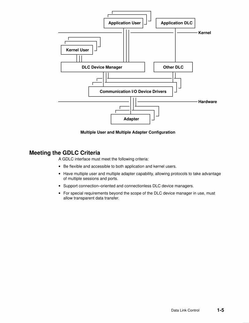
A device manager written in accordance with GDLC specifications runs on all the operatingsystem hardware configurations containing a communications device driver and its targetadapter. Each device manager supports multiple users above and below the kernel. Ingeneral, users operate concurrently over a single adapter, or each user operates overmultiple adapters. DLC device managers vary based on their protocol constraints.
The Multiple User and Multiple Adapter Configuration figure illustrates a multiple userconfiguration.
Data Link Control 1-5
Application User
Kernel User
Adapter
Kernel
Application DLC
Other DLCDLC Device Manager
Communication I/O Device Drivers
Hardware
Multiple User and Multiple Adapter Configuration
Meeting the GDLC Criteria A GDLC interface must meet the following criteria:
• Be flexible and accessible to both application and kernel users.
• Have multiple user and multiple adapter capability, allowing protocols to take advantageof multiple sessions and ports.
• Support connection–oriented and connectionless DLC device managers.
• For special requirements beyond the scope of the DLC device manager in use, mustallow transparent data transfer.

1-6 AIX Communications Programming Concepts
Implementing GDLC Interface Each data link control (DLC) device manager operates in the kernel as a standard /deventry of a multiplexed device manager for a specified protocol. For an adapter not in use byDLC, each open subroutine to a DLC device manager creates a kernel process. An opensubroutine is also issued to the target adapter’s device handler. If needed, issue additionalopen subroutines for multiple DLC adapter ports of the same protocol. Any open subroutinetargeting the same port does not create additional kernel processes, but links the opensubroutine with the existing process. Each active port always uses one kernel process.
The internal structure of a DLC device manager has the same basic structure as a kerneldevice handler, except that a kernel process replaces the interrupt handler in asynchronousevents. The Read, Write, I/O Control, and Select blocks function as set forth in the StandardKernel Device Manager figure.
dlcwrite dlcioctl dlcread dlcselect
Write I/OControl
To the Device Handler From the Device Handler
From the User
Read InterruptHandler
Select
Standard Kernel Device Manager
Use the information in the following table to add an installed DLC.
Note: A data link control (DLC) must be installed before adding it to the system.
Add an Installed DLC Tasks
Web-based System Manager: wsm network fast path (wsm network application)
–OR–
Task SMIT Fast Path Command or File
Add an Installed DLC Choose one (depending on type): smit cmddlc_sdlc smit cmddlc_token smit cmddlc_qllc smit cmddlc_ether (see note) smit cmddlc_fddi
mkdev
Note: The SMIT fast path to add an Ethernet device manager includes both StandardEthernet and IEEE 802.3 Ethernet device managers.

Data Link Control 1-7
GDLC Interface ioctl Entry Point Operations The generic data link control (GDLC) interface supports the following ioctl subroutineoperations:
DLC_ENABLE_SAP Enables a service access point (SAP).
DLC_DISABLE_SAP Disables a SAP.
DLC_START_LS Starts a link station on a particular SAP as a caller orlistener.
DLC_HALT_LS Halts a link station (LS).
DLC_TRACE Traces a link station’s activity for short or long activities.
DLC_CONTACT Contacts a remote station for a particular local linkstation.
DLC_TEST Tests the link to a remote for a particular local linkstation.
DLC_ALTER Alters a link station’s configuration parameters.
DLC_QUERY_SAP Queries statistics of a particular SAP.
DLC_QUERY_LS Queries statistics of a particular link station.
DLC_ENTER_LBUSY Enters local–busy mode on a particular link station.
DLC_EXIT_LBUSY Exits local–busy mode on a particular link station.
DLC_ENTER_SHOLD Enters short–hold mode on a particular link station.
DLC_EXIT_SHOLD Exits short–hold mode on a particular link station.
DLC_GET_EXCEP Returns asynchronous exception notifications to theapplication user.
Note: This ioctl subroutine operation is not used bythe kernel user since all exception conditionsare passed to the kernel user by way of theirexception handler.
DLC_ADD_GRP Adds a group or multicast receive address to a port.
DLC_ADD_FUNC_ADDR Adds a group or multicast receive functional address toa port.
DLC_DEL_FUNC_ADDR Removes a group or multicast receive functionaladdress from a port.
DLC_DEL_GRP Removes a group or multicast address from a port.
IOCINFO Returns a structure that describes the GDLC devicemanager. See the /usr/include/sys/devinfo.h fileformat for more information.
Service Access PointsA service access point (SAP) identifies a particular user service that sends and receives aspecific class of data. This user service allows different classes of data to be routedseparately to their corresponding service handlers. Those DLCs that support multipleconcurrent SAPs have addresses known as destination SAP and source SAP embedded intheir packet headers. DLCs that can only support a single SAP do not need or use SAPaddressing, but still have the concept of enabling the one SAP. In general, SAP is enabledfor each DLC user on each port.

1-8 AIX Communications Programming Concepts
Most SAP address values are defined by IEEE standardized network–management entitiesor user–defined values as specified in the Token–Ring Network Architecture Reference.Some of the common SAP addresses are:
null SAP (0x00) Provides some ability to respond to remote nodes evenwhen no SAP has been enabled. This SAP supportsonly connectionless service and responds only toexchange identification (XID) and TEST Link ProtocolData Units (LPDU).
SNA path control (0x04) Denotes the default individual SAP address used bySystems Network Architecture (SNA) nodes.
PC network NETBIOS (0xF0) Used for all DLC communication that is driven byNetwork Basic I/O System (NetBIOS) emulation.
discovery SAP (0xFC) Used by the local area network (LAN) name–discoveryservices.
global SAP (0xFF) Identifies all active SAPs.
Note: See Request for Comment (RFC)1060 for examples of IEEE 802 Local SAP values.RFCs are available from the Network Information Center at SRI International, MenloPark, California.
Link StationsA link station (LS) identifies an attachment between two nodes for a particular SAP pair.This attachment can operate as a connectionless service (datagram) orconnection–oriented service (fully sequenced data transfer with error recovery). In general,one LS is started for each remote attachment.
Local–Busy ModeWhen an LS operates in a connection–oriented mode, it needs to stop the remote station’ssending of information packets for reasons such as resource outage. Notification can thenbe sent to the remote station to cause the local station to enter local–busy mode. Onceresources are available, the local station notifies the remote that it is no longer busy andthat information packets can flow again. Only sequenced information packets are haltedwith local–busy mode. All other types of data are unaffected.
Short–Hold ModeUse the short–hold mode of operation when operating over data networks with the followingcharacteristics:
• Short call–setup time
• Tariff structure that specifies a relatively small fee for the call setup compared to thecharge for connect time
During short–hold mode, an attachment between two stations is maintained only to transferdata available between the two stations. When no data is sent, the attachment is clearedafter a specified time–out period and is only reestablished to transfer new data.
Testing and Tracing LinksTo test an attachment between two stations, instruct an LS to send a test packet from thelocal station. This packet is echoed back from the remote station if the attachment isoperating correctly.
Some data links are limited in their support of this function due to protocol constraints.Synchronous data link control (SDLC), for example, only generates the test packet from thehost or primary station. Most other protocols, however, allow test packets to be initiated fromeither station.

Data Link Control 1-9
To trace a link, line data and special events (such as station activation, termination, and timeouts) can be logged in the generic trace facility for each LS. This function helps determinethe cause of certain communications attachment problems. The GDLC user can selecteither short or long entries to be traced.
Short entries consist of up to 80 bytes of line data, while long entries allow full packets ofdata to be traced.
Tracing can be activated when an LS is started, or it can be dynamically activated orterminated at any time afterward.
StatisticsBoth SAP and LS statistics can be queried by a GDLC user. The statistics for a SAP consistof the current SAP state and information about the device handler. LS statistics consist ofthe current station states and various reliability, availability, and serviceability counters thatmonitor the activity of the station from the time it is started.

1-10 AIX Communications Programming Concepts
GDLC Special Kernel Services Generic data link control (GDLC) provides special services for a kernel user. However, atrusted environment must exist within the kernel. Instead of the DLC device managercopying asynchronous event data into user space, the kernel user must specify functionpointers to special routines called function handlers. Function handlers are called by DLC atthe time of execution. This process allows maximum performance between the kernel userand the DLC layers. Each kernel user is required to restrict the number of function handlersto a minimum path length and use the communications memory buffer (mbuf) scheme.
Attention: A function handler must never call another DLC entry directly. Direct callsmade under lock cause a fatal sleep. The only exception to this rule is when a kerneluser may call the dlcwritex entry point during its service of any of the four receive datafunctions. Calling the dlcwritex entry point allows immediate responses to be generatedwithout an intermediate task switch. Special logic is required within the DLC devicemanager to check the process identification of the user calling a write operation. If it is aDLC process and the internal queuing capability of the DLC has been exceeded, thewrite is sent back with an error code (EAGAIN value) instead of putting the callingprocess (DLC) to sleep. It is then up to the calling user subroutine to return a specialnotification to the DLC from its receive–data function to ensure a retry of the receivebuffer at a later time.
The user–provided function handlers are:
datagram datareceived
Called any time a datagram packet is received for the kerneluser.
exception condition Called any time an asynchronous event occurs that must notifythe kernel user, such as SAP Closed or Station Contacted.
I–frame data received Called each time a normal sequenced data packet is receivedfor the kernel user.
network data received Called any time network–specific data is received for the kerneluser.
XID data received Called any time an exchange identification (XID) packet isreceived for the kernel user.
The dlcread and dlcselect entry points for DLC are not called by the kernel user becausethe asynchronous functional entries are called directly by the DLC device manager.Generally, any queuing of these events must occur in the user’s function handler. If,however, the kernel user cannot handle a particular receive packet, the DLC devicemanager may hold the last receive buffer and enter one of two special user–busy modes:
user–terminated busy mode (I–frame only)If the kernel user cannot handle a received I–frame (due to problems suchas queue blockage), a DLC_FUNC_BUSY return code is given back, andDLC holds the buffer pointer and enters local–busy mode to stop theremote station’s I–frame transmissions. The kernel user must call the exitlocal–busy function to reset local–busy mode and start the reception ofI–frames again. Only normal sequenced I–frames can be stopped. XID,datagram, and network data are not affected by local–busy mode.
timer–terminated busy mode (all frame types)If the kernel user cannot handle a particular receive packet and wants DLCto hold the receive buffer for a short period and then recall the user’sreceive function, a DLC_FUNC_RETRY return code is sent back to DLC. Ifthe receive packet is a sequenced I–frame, the station enters local–busymode for that period. In all cases, a timer is started; once the timer expires,the receive–data functional entry is called again.

Data Link Control 1-11
GDLC Problem Determination Each generic data link control (GDLC) provides problem determination data that can beused to isolate network problems. Four types of diagnostic information are provided:
• DLC Status Information, on page 1-11
• DLC Error Log, on page 1-12
• DLC Link Station Trace Facility, on page 1-12
• LAN Monitor Trace (see AIX 4.3 System Management Guide: Communications andNetworks)
DLC Status Information Status information can be obtained for a service access point (SAP) or a link station (LS)using the DLC_QUERY_SAP and DLC_QUERY_LS ioctl subroutines to call the specificDLC kernel device manager in use.
The DLC_QUERY_SAP ioctl subroutine obtains individual device driver statistics fromvarious devices:
• Token ring
• Ethernet
• Multiprotocol
The DLC_QUERY_LS ioctl subroutine obtains LS statistics from various DLCs. Thesestatistics include data link protocol counters. Each counter is reset by the DLC during theDLC_START_LS ioctl subroutine and generally runs continuously until the LS is terminatedand its storage is freed. If a counter reaches the maximum count, the count is frozen and nowraparound occurs.
The suggested counters provided by a DLC device manager are listed as follows. SomeDLCs can modify this set of counters based on the specific protocols supported. Forexample, the number of rejects or receive–not–ready packets received might be meaningful.
test commands sent Contains a binary count of the test commands sent to theremote station by GDLC, in response to test commandsissued by the user.
test command failures Contains a binary count of the test commands that did notcomplete properly due to problems such as:
• Incorrect response
• Bad data comparison
• Inactivity
test commands received Contains a binary count of valid test commands received,regardless of whether the response is completed correctly.
sequenced data packetstransmitted
Contains a binary count of the total number of normalsequenced data packets transmitted to the remote LS.
sequenced data packetsretransmitted
Contains a binary count of the total number of normalsequenced data packets retransmitted to the remote LS.
maximum contiguousretransmissions
Contains a binary count of the maximum number of times asingle data packet has been retransmitted to the remote LSbefore acknowledgment. This counter is reset each time avalid acknowledgment is received.
sequenced data packetsreceived
Contains a binary count of the total number of normalsequenced data packets correctly received.

1-12 AIX Communications Programming Concepts
invalid packets received Contains a binary count of the number of invalid commandsor responses received, including invalid control bytes,incorrect I–fields, and overflowed I–fields.
adapter–detected receiveerrors
Contains a binary count of the number of receive errorsreported back from the device driver.
adapter–detected transmiterrors
Contains a binary count of the number of transmit errorsreported back from the device driver.
receive inactivity timeouts Contains a binary count of the number of receive time outsthat have occurred.
command polls sent Contains a binary count of the number of command packetssent that requested a response from the remote LS.
command repolls sent Contains a binary count of the total number of commandpackets retransmitted to the remote LS due to a lack ofresponse.
command contiguousrepolls
Contains a binary count of the number of times a singlecommand packet was retransmitted to the remote LS due toa lack of response. This counter is reset each time a validresponse is received.
DLC Error Log Each DLC provides entries to the system error log whenever errors are encountered. To callthe kernel error collector, use the errsave kernel service.
The error conditions are reported by the system–product error log using the error logdaemon (errdemon).
The user can obtain formatted error–log data by issuing the errpt command. When usedwith the –N DLCName flag, the errpt command produces a summary report of all the errorlog entries for the resource name indicated by the DLCName parameter. Valid values for theDLCName parameter include:
SYSXDLCE Indicates a Standard Ethernet datalink.
SYSXDLCI Indicates an IEEE 802.3 Ethernet datalink.
SYSXDLCT Indicates a token–ring datalink.
SYSXDLCS Indicates an synchronous data link control (SDLC) datalink.
The format of each required alert vector can be found in Appendix A of SNA Format andProtocol Reference Manual: Management Services.
For more information on the error log facility, refer to ”Error Logging Overview”AIX Version4.3 Problem Solving Guide and Reference.
DLC Link Station Trace Facility GDLC provides optional entries to a generic system trace channel as required by thesystem product Reliability/Availability/Serviceability (RAS). The default is trace–disabled,provides maximum performance, and reduces the number of system resources used. Forinformation on additional trace facilities, see ”DLC Local Area Network Monitor Trace” inAIX 4.3 System Management Guide: Communications and Networks.

Data Link Control 1-13
Trace Channels The operating system supports up to seven generic trace channels in operation at the sametime. Before starting an LS trace, a user must allocate a channel with the DLC_START_LSioctl operation or the DLC_TRACE ioctl operation. Begin the trace sessions with the trcstartand trcon subroutines.
Trace activity in the LS must be stopped either by halting the LS or by issuing aDLC_TRACE ioctl operation to that station. Once the LS has stopped tracing, the channel isdisabled with the trcoff subroutine and returned to the system with the trcstop subroutine.
Trace Reports The user can obtain formatted trace log data by issuing the trcrpt command with theappropriate file name, such as:
trcrpt /tmp/link1.log
This example produces a detailed report of all link trace entries in the /tmp/link1.log file,provided a prior trcstart subroutine specified the /tmp/link1.log file as the –o name for thetrace log.
Trace Entries For each trace entry, GDLC generates the trcgenkt kernel service to the kernel generictrace.
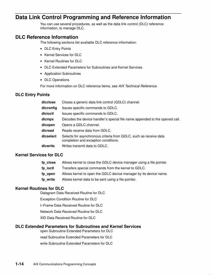
1-14 AIX Communications Programming Concepts
Data Link Control Programming and Reference Information You can use several procedures, as well as the data link control (DLC) referenceinformation, to manage DLC.
DLC Reference InformationThe following sections list available DLC reference information:
• DLC Entry Points
• Kernel Services for DLC
• Kernel Routines for DLC
• DLC Extended Parameters for Subroutines and Kernel Services
• Application Subroutines
• DLC Operations
For more information on DLC reference items, see AIX Technical Reference.
DLC Entry Points
dlcclose Closes a generic data link control (GDLC) channel.
dlcconfig Issues specific commands to GDLC.
dlcioctl Issues specific commands to GDLC.
dlcmpx Decodes the device handler’s special file name appended to the opened call.
dlcopen Opens a GDLC channel.
dlcread Reads receive data from GDLC.
dlcselect Selects for asynchronous criteria from GDLC, such as receive datacompletion and exception conditions.
dlcwrite Writes transmit data to GDLC.
Kernel Services for DLC
fp_close Allows kernel to close the GDLC device manager using a file pointer.
fp_ioctl Transfers special commands from the kernel to GDLC.
fp_open Allows kernel to open the GDLC device manager by its device name.
fp_write Allows kernel data to be sent using a file pointer.
Kernel Routines for DLCDatagram Data Received Routine for DLC
Exception Condition Routine for DLC
I–Frame Data Received Routine for DLC
Network Data Received Routine for DLC
XID Data Received Routine for DLC
DLC Extended Parameters for Subroutines and Kernel Servicesopen Subroutine Extended Parameters for DLC
read Subroutine Extended Parameters for DLC
write Subroutine Extended Parameters for DLC

Data Link Control 1-15
Application Subroutines
close Subroutine Interface for Data Link Control Manager
ioctl Subroutine Interface for Data Link Control Manager
open Subroutine Interface for Data Link Control Manager
readx Subroutine Interface for Data Link Control Manager
select Subroutine Interface for Data Link Control Manager
writex Subroutine Interface for Data Link Control Manager
DLC Operationsioctl Operations (op) for DLC
Parameter Blocks by ioctl Operation for DLC
DLC Programming ProceduresAdding an Installed DLC in Implementing GDLC Interface.
Listing, changing or removing DLC Attributes in Managing DLC Device Drivers in AIX 4.3System Management Guide: Communications and Networks.

1-16 AIX Communications Programming Concepts
Token–Ring Data Link Control Overview The token–ring data link control (DLCTOKEN) is a device manager that follows the genericdata link control (GDLC) interface definition. This DLC device manager provides an accessprocedure to transfer four types of data over a token ring:
• Datagrams
• Sequenced data
• Identification data
• Logical link controls
This DLC device manager also provides a pass–through capability that allows transparentdata flow.
The token-ring device handler and the Token–Ring High Performance Network Adaptertransfer the data, with address checking, token generation, or frame check sequences.
For more information on DLCTOKEN, see:
• DLCTOKEN Device Manager Nodes, on page 1-17
• DLCTOKEN Device Manager Functions, on page 1-19
• DLCTOKEN Protocol Support, on page 1-20
• DLCTOKEN Name–Discovery Services, on page 1-22
• DLCTOKEN Direct Network Services, on page 1-25
• DLCTOKEN Connection Contention, on page 1-26
• Initiating DLCTOKEN Link Sessions, on page 1-27
• Stopping DLCTOKEN Link Sessions, on page 1-28
• DLCTOKEN Programming Interfaces, on page 1-29.

Data Link Control 1-17
DLCTOKEN Device Manager Nodes The token–ring data link control (DLCTOKEN) device manager operates between two ormore nodes on the token–ring local area network (LAN) using IEEE 802.2 procedures andcontrol information as defined in the Token–Ring Network Architecture Reference. Protocolsupport includes:
• Asynchronous disconnected mode (ADM) and asynchronous balanced mode extended(ABME)
• Two–way simultaneous (full–duplex) data flow
• Multiple point–to–point logical attachments on the LAN using network and service accesspoint addresses
• Peer–to–peer relationship with remote station
• Both name–discovery and address–resolve services
• Source–routing generation for up to eight bridge hops.
DLCTOKEN provides full–duplex, peer–data transfer capabilities over a token–ring LAN.The token–ring LAN must use the token–ring IEEE 802.5 medium access control (MAC)procedure and a superset of the IEEE 802.2 logical link control (LLC) protocol, as describedin the Token–Ring Network Architecture Reference.
Multiple token–ring adapters are supported with a maximum of 254 service access point(SAP) users per adapter. A total of 255 link stations (LS) per adapter are supported and aredistributed among active SAP users. Multiple ring segments can be accessed usingtoken–ring network bridge facilities, with up to eight consecutive ring segments supportedbetween any two nodes.
LLC refers to the manager, access–channel, and LS subcomponents of a generic data linkcontrol (GDLC) component, such as DLCTOKEN device manager, as illustrated in theDLCTOKEN Component Structure figure.
Link Station
Access Channel ControlDLCMgr
UserPhysicalUnitServices
LLC
MAC
1
1
Medium Access Control
2
2
n
1
2
k
DLCTOKEN Component
User Data Services
DLCTOKEN Component Structure

1-18 AIX Communications Programming Concepts
Each LS controls the transfer of data on a single logical link. The access channel performsmultiplexing and demultiplexing for message units flowing from each LS and manager to theMAC. The DLC manager performs the following actions:
• Establishes and stops connections
• Creates and deletes an LS
• Routes commands to the proper station.

Data Link Control 1-19
DLCTOKEN Device Manager Functions The token–ring data link control (DLCTOKEN) device manager and transport medium–usetwo–functional layers, medium access control (MAC) and logical link control (LLC), tomaintain reliable link–level connections, guarantee data integrity, and negotiate exchangesof identification. Both connectionless (Type 1) and connection–oriented (Type 2) servicesare supported.
The token–ring adapter and the DLCTOKEN device handler perform the following MACfunctions:
• Handling ring–insertion protocol
• Handling token detection and creation
• Encoding and decoding the serial bit–stream data
• Checking received network, group, and functional addresses
• Routing of received frames based on the LLC or MAC indicator and using the destinationservice access point (SAP) address if an LLC frame was received
• Generating cyclic redundancy checks (CRC)
• Handling frame delimiters, such as start or end delimiters and frame status fields.
• Handling fail–safe time outs.
DLCTOKEN performs additional MAC functions, such as:
• Framing control fields on transmit frames
• Network–addressing on transmit frames
• Routing information on transmit frames.
DLCTOKEN is also responsible for all LLC functions:
• Handling remote connection services and bridge routing, using the address–resolve andname–discovery procedures
• Sequencing of link stations on a given port
• Generating SAP addresses on transmit frames
• Generating IEEE 802.2 LLC commands and responses on transmit frames
• Recognizing and routing of received frames to the proper SAP
• Servicing IEEE 802.2 LLC commands and responses on receive frames
• Handling frame sequencing and retries
• Handling fail–safe and inactivity time outs
• Handling reliability/availability/serviceability (RAS) counters, error logs, and link traces.

1-20 AIX Communications Programming Concepts
DLCTOKEN Protocol SupportThe token–ring data link control (DLCTOKEN) supports the logical link control (LLC)protocol and state tables described in the Token–Ring Network Architecture Reference,which also contains the local area network (LAN) IEEE 802.2 LCC standard. Bothaddress–resolve services and name–discovery services are supported for establishingremote connections. DLCTOKEN supports a direct network interface to allow a user totransmit and receive unnumbered information packets directly through DLCTOKEN withoutthe data link layer performing any protocol handling.
Station TypesA combined station is supported for a balanced (peer–to–peer) configuration on a logicalpoint–to–point connection. That allows either station to initiate asynchronously thetransmission of commands at any response opportunity. The sender in each combinedstation controls the receiver in the other station. Data transmissions then flow as primarycommands, and acknowledgments and status flow as secondary responses.
Response ModesBoth asynchronous disconnect mode (ADM) and asynchronous balanced mode extended(ABME) are supported. ADM is entered by default whenever a link session is initiated, andis switched to ABME only after the set asynchronous balanced mode extended (SABME)command sequence is complete. Once operating in ABME, information frames containinguser data can be transferred. ABME then remains active until the LLC session terminates,which occurs because of a disconnect (DISC) command packet sequence or a major linkerror.
Token–Ring Data PacketAll communication between a local and remote station is accomplished by the transmissionof a packet that contains token–ring headers and trailers as well as an encapsulated LLCLink Protocol Data Unit (LPDU). The DLCTOKEN Frame Encapsulation figure illustrates thetoken–ring data packet.
DSAPAddr.
SSAPAddr.
ControlField
InformationField
2 bytes p bytes1 (2) byte
DestinationAddress
SourceAddress
RoutingInformation
LPDU CRC
6 bytes 6 bytes m bytes
SD
AC
FC
4 2
ED
FS
n bytes3
DLCTOKEN Frame Encapsulation
The token–ring data packet consists of the following fields:
SD Starting delimiter
AC Access control field
FC Frame control field
LPDU LLC Link Protocol Data Unit
DSAP Destination service access point (SAP) address field
SSAP Source SAP address field

Data Link Control 1-21
CRC Cyclic redundancy check or frame–check sequence
ED Ending delimiter
FS Frame status field
m bytes Integer value greater than or equal to 0 and less than or equal to 18
n bytes Integer value greater than or equal to 3 and less than or equal to 4064
p bytes Integer value greater than or equal to 0 and less than or equal to 4060
Note: SD, CRC, ED, and FS headers are added and deleted by the hardware adapter.

1-22 AIX Communications Programming Concepts
DLCTOKEN Name–Discovery Service In addition to the standard IEEE 802.2 Common Logical Link Protocol support and addressresolution services, token–ring data link control (DLCTOKEN) also provides aname–discovery service that allows the operator to identify local and remote stations byname instead of by 6–byte physical addresses. Each port must have a unique name of up to20 characters on the network. The character set used varies depending on the user’sprotocol. Systems Network Architecture (SNA), for example, requires character set A.Additionally, each new service access point (SAP) supported on a particular port can have aunique name if desired.
Each name is added to the network by broadcasting a find (local name) request when thenew name is being introduced to a given network port. If no response other than an echoresults from the find (local name) request after it is sent the specified number of times, thephysical link is declared opened. The name is then assigned to the local port and SAP. Ifanother port on the network has already added the name, a name–found response is sentto the station that issued the find request. A result code (DLC_NAME_IN_USE) indicatesthat the new attachment was unsuccessful and a different name must be chosen. Calls areestablished by broadcasting a find (remote name) request to the network and waiting for aresponse from the port with the specified name. Only ports that have listen attachmentspending, receive colliding find requests, or are already attached to the requesting remotestation answer a find request.
LAN Find Data FormatFind Header
0–1 Byte length of the find packet including the length field
2–3 Key 0x0001
4–n Remaining control vectors
Target Name
0–1 Vector length = 0x000F to 0x0022
2–3 Key 0x0004
4–9 Name structure architecture ID:
4–5 Subvector length = 0x0006
6–7 Key 0x4011
8–9 Identifier = 0x8000 (locally administered)
10–m Object name:
10–11 Subvector length = 0x0005 to 0x000C
12–13 Key 0x4010
14–m Target’s name (1 to 20 bytes)

Data Link Control 1-23
Source Name
0–1 Vector length = 0x000F to 0x0022
2–3 Key 0x000D
4–9 Name structure architecture ID:
4–5 Subvector length = 0x0006
6–7 Key 0x4011
8–9 Identifier = 0x8000 (locally administered)
10–p Object name:
10–11 Subvector length = 0x0005 to 0x000C
12–13 Key 0x4010
14–p Source’s name (1 to 20 bytes)
Correlator
0–1 Vector length = 0x0008
2–3 Key 0x4003
4–7 Correlator value:
Byte 4 Bit 0 1 means this is a SAP correlator for a find (self)
Byte 4 Bit 0 0 means this is an LS correlator for a find (remote)
Source Medium Access Control (MAC) Address
0–1 Vector length = 0x000A
2–3 Key 0x4006
4–9 Source’s MAC address (6 bytes)
Source SAP
0–1 Vector length = 0x0005
2–3 Key 0x4007
4 Source’s SAP address
LAN Found Data FormatFound Header
0–1 Byte length of the found packet including the length field
2–3 Key 0x0002
4–n Remaining control vectors

1-24 AIX Communications Programming Concepts
Correlator
0–1 Vector length = 0x0008
2–3 Key 0x4003
4–7 Correlator value:
Byte 4 Bit 0 1 means this is a SAP correlator for a find (self).
Byte 4 Bit 0 0 means this is an LS correlator for a find (remote).
Source MAC Address
0–1 Vector length = 0x000A
2–3 Key 0x4006
4–9 Source’s MAC address (6 bytes)
Source SAP
0–1 Vector length = 0x0005
2–3 Key 0x4007
4 Source’s SAP address
Response Code
0–1 Vector length = 0x0005
2–3 Key 0x400B
4 Response code:
B’0xxx xxxx’ Positive response
B’0000 0001’ Resources available
B’1xxx xxxx’ Negative response
B’1000 0001’ Insufficient resources
Bridge Route DiscoveryDLCTOKEN caches any returned bridge–routing information from a remote station on eachpacket received and generates send–packet headers with the reverse route. This operationallows dynamic alteration of the bridge route taken throughout the link station attachment.There is also a provision to alter the cached routing field with the DLC_ALT_RTE ioctloperation. This ioctl operation allows the user to change the bridge route taken by linkstation send packets dynamically throughout the attachment as long as an alternate routeexists. Once the DLC_ALT_RTE ioctl operation has been issued, dynamic caching of thereceived route is stopped for the link station, and all send packets carry the ioctl operation’srouting value.
Network data packets are not associated with a link station attachment, so any bridgerouting field has to come from the user sending the packet. DLCTOKEN has no involvementin the bridge routing of network data cases.

Data Link Control 1-25
DLCTOKEN Direct Network Services Some users wish to handle their own unnumbered information packets on the networkwithout the aid of the data link layer within the token–ring data link control (DLCTOKEN). Adirect network interface allows an entire packet to be generated and sent by a user once theuser service access point (SAP) has been opened. The interface allows full control of everyfield in the data link header for each write call issued. Also provided is the ability to view theentire packet contents on received frames. The criteria for a direct network write are:
• The local SAP must be valid and opened.
• The data link control byte must indicate unnumbered information (0x03).

1-26 AIX Communications Programming Concepts
DLCTOKEN Connection Contention Dual paths to the same nodes are detected by the token–ring device manager in one of twoways. First, when a call is in progress to a remote node that is also trying to call the localnode, the incoming find (remote name) request is treated as if a local listen wereoutstanding. Second, when a pending local listen is acquired by a call from a remote nodeand the local user issues a call to the active remote node, a result code(DLC_REMOTE_CONN) is returned with the link station correlator of the active attachment,allowing the user to relink attachment pointers.
Data Link Control 1-27
Initiating DLCTOKEN Link Sessions When a link station (LS) is opened, the token–ring data link control (DLCTOKEN) isinitialized at the open LS as a combined station in asynchronous disconnect mode (ADM).As a secondary or combined station, DLCTOKEN is in a receive state waiting for acommand frame from the primary or combined station. The following command frames areaccepted by the secondary or combined station at this time:
SABME Set asynchronous balanced mode extended
XID Exchange station identification
TEST Test link
UI Unnumbered information – datagram
DISC Disconnect
Any other command frame is ignored. Once a SABME is received, the station is ready fornormal data transfer and the following frames are also accepted:
I Information
RR Receive ready
RNR Receive not ready
REJ Reject
As a primary or combined station, DLCTOKEN can perform ADM XID, ADM TESTexchanges, send datagrams, or connect the remote to the asynchronous balanced modeextended (ABME). XID exchanges allow the primary or combined station to send out itsstation–specific identification to the secondary or combined station and obtain a response.Once an XID response is received, any attached information field is passed to the user forfurther action.
TEST exchanges allow the primary or combined station to send out a buffer of informationthat will be echoed by the secondary or combined station in order to test the integrity of thelink.
Initiation of the normal data exchange mode, ABME, causes the primary or combinedstation to send an SABME to the secondary or combined station. Once sent successfully,the connection is said to be contacted and the user is notified. Information frames can nowbe sent and received between the linked stations.

1-28 AIX Communications Programming Concepts
Stopping DLCTOKEN Link Sessions The user or the remote station can be stopped by the token–ring data link control(DLCTOKEN):
• Issue a DLC_HALT_LS command. This command will cause the primary or combinedstation to initiate a disconnect (DISC) packet sequence.
• Sending a DISC command packet as a primary or combined station.
• Receiving an inactivity timeout can stop a DLCTOKEN link session. This action is usefulin detecting a loss of connection in the middle of a session.
Note: Abnormal stopping is caused by certain protocol violations or by resource outages.

Data Link Control 1-29
DLCTOKEN Programming Interfaces The token–ring data link control (DLCTOKEN) conforms to the generic data link control(GDLC) guidelines except where noted below. Additional structures and definitions forDLCTOKEN can be found in the /usr/include/sys/trlextcb.h file.
Note: The dlc prefix is replaced with the trl prefix for DLCTOKEN.
trlclose DLCTOKEN is fully compatible with the dlcclose GDLC interface.
trlconfig DLCTOKEN is fully compatible with the dlcconfig GDLC interface. Noinitialization parameters are required.
trlmpx DLCTOKEN is fully compatible with the dlcmpx GDLC interface.
trlopen DLCTOKEN is fully compatible with the dlcopen GDLC interface.
trlread DLCTOKEN is compatible with the dlcread GDLC interface with the followingconditions:
• The readx subroutines can have DLCTOKEN data link header informationprefixed to the I–field being passed to the application. This is optionalbased on the readx subroutine data link header length extension parameterin the gdl_io_ext structure.
• If this field is nonzero, DLCTOKEN copies the data link header and theI–field to user space and sets the actual length of the data link header intothe length field.
• If the field is 0, no data link header information is copied to user space. Seethe DLCTOKEN Frame Encapsulation figure, on page 1-31 for moredetails.
The following kernel receive packet function handlers always have the DLCTOKEN datalink header information within the communications memory buffer (mbuf) and can locate itby subtracting the length passed (in the gdl_io_ext structure) from the data offset field ofthe mbuf structure.
trlselect DLCTOKEN is fully compatible with the dlcselect GDLC interface.
trlwrite DLCTOKEN is compatible with the dlcwrite GDLC interface, with theexception that network data can only be written as an unnumberedinformation (UI) packet and must have the complete data link headerprefixed to the data. DLCTOKEN verifies that the local (source) serviceaccess point (SAP) is enabled and that the control byte is UI (0x03). See theDLCTOKEN Frame Encapsulation figure, on page 1-31 for more details.
trlioctl DLCTOKEN is compatible with the dlcioctl GDLC interface, with conditionson the following operations:
• DLC_ENABLE_SAP
• DLC_START_LS
• DLC_ALTER
• DLC_QUERY_SAP
• DLC_QUERY_LS
• DLC_ENTER_SHOLD
• DLC_EXIT_SHOLD
• DLC_ADD_GROUP
• DLC_ADD_FUNC_ADDR
• DLC_DEL_FUNC_ADDR
• DLC_DEL GRP
• IOCINFO
The following sections describe these conditions in detail.

1-30 AIX Communications Programming Concepts
DLC_ENABLE_SAP The ioctl subroutine argument structure for enabling a SAP (dlc_esap_arg) has thefollowing specifics:
• The grp_addr (group address) field for the token ring contains the four least significantbytes of the desired six–byte group address. Only bits 1 through 31 are valid. Bit 0 isignored. The most significant two bytes are automatically compared for 0xC000 by theadapter.
• The func_addr_mask (functional address mask) field must be the logical OR operationwith the functional address on the adapter, which allows packets that are destined forspecified functions to be received by the local adapter. Only bits 1 through 29 are valid.Bits 0, 30, and 31 are ignored. The most significant two bytes of the full six–bytefunctional address are automatically compared for 0xC000 by the adapter.
The following is an example of a Network Basic Input/Output System (NetBIOS)functional address:
To select the NETBIOS functional address of 0xC000_0000_0080,
the functional address mask is set to 0x0000_0080.
Note: DLCTOKEN does not check to determine whether a received packet was acceptedby the adapter due to a preset network address, group address, or functionaladdress.
• The max_ls (maximum link stations) field cannot exceed 255 bytes.
• The following common SAP flags are not supported:
ENCD Specifies a synchronous data link control (SDLC) serial encoding.
NTWK Indicates a teleprocessing network type.
LINK Indicates a teleprocessing link type.
PHYC Indicates a physical network call (teleprocessing).
ANSW Indicates a teleprocessing autocall and autoanswer.
• Group SAPs are not supported, so the num_grp_saps (number of group SAPs) field mustbe set to 0.
• The laddr_name (local address and name) field and its associated length are only usedfor name discovery when the common SAP flag ADDR is set to 0. When resolveprocedures are used (that is, the ADDR flag is set to 1), DLCTOKEN obtains the localnetwork address from the device handler and not from the dlc_esap_arg structure.
• The local_sap (local service access point) field can be set to any value except null SAP(0x00) or discovery SAP (0xFC). Also, the low–order bit must be set to 0 (B‘nnnnnnn0’) toindicate an individual address.
• No protocol–specific data area is required for DLCTOKEN to enable a SAP.
DLC_START_LSThe ioctl subroutine argument structure for starting a link station (dlc_sls_arg) has thefollowing specifics:
• These following common link station (LS) flags are not supported:
STAT Specifies a station type for SDLC.
NEGO Specifies a negotiable station type for SDLC.
• The raddr_name (remote address and name) field is only used for outgoing calls whenthe DLC_SLS_LSVC common LS flag is active.

Data Link Control 1-31
• The maxif (maximum I–field length) field can be set to any value greater than 0. See theDLCTOKEN frame encapsulation figure, on page 1-31 for more details. DLCTOKENadjusts this value to a maximum of 4060 bytes if set too large.
• The rcv_wind (receive window) field can be set to any value between 1 and 127 inclusive.The recommended value is 127.
• The xmit_wind (transmit window) field can be set to any value between 1 and 127inclusive. The recommended value is 26.
• The rsap (remote SAP) field can be set to any value except null SAP (0x00) orname–discovery SAP (0xFC). Also, the low–order bit must be set to 0 (B‘nnnnnnn0’) toindicate an individual address.
• The max_repoll field can be set to any value from 1 to 255. The recommended value is 8.
• The repoll_time field is defined in increments of 0.5 seconds and can be set to any valuefrom 1 to 255, inclusive. The recommended value is 2, giving a time–out duration of 1 to1.5 seconds.
• The ack_time (acknowledgment time) field is defined in increments of 0.5 seconds, andcan be set to any value between 1 and 255, inclusive. The recommended value is 1,giving a time–out duration of 0.5 to 1 second.
• The inact_time (inactivity time) field is defined in increments of 1 second and can be setto any value between 1 and 255 inclusive. The recommended value is 48, giving atime–out duration of 48 to 48.5 seconds.
• The force_time (force halt time) field is defined in increments of 1 second and can be setto any value between 1 and 16383, inclusive. The recommended value is 120, giving atime–out duration of approximately 2 minutes.
• A protocol–specific data area must be appended to the generic start link station argument(dlc_sls_arg). This structure provides DLCTOKEN with additional protocol–specificconfiguration parameters:
struct trl_start_psd
{
uchar_t pkt_prty; /* ring access packet priority */
uchar_t dyna_wnd; /* dynamic window increment */
ushort_t reserved; /* currently not used */
};

1-32 AIX Communications Programming Concepts
The protocol–specific parameters are:
pkt_prty Specifies the ring access priority that the user wishes to reserve ontransmit packets. Values of 0 to 3 are supported, where 0 is the lowestpriority and 3 is the highest priority.
dyna_wnd Specifies the number of consecutive sequenced packets that must beacknowledged by the remote station before the local transmit windowcount can be incremented. Network congestion causes the local transmitwindow count to drop automatically to a value of 1. The dynamic windowincrement allows a gradual increase in network traffic after a period ofcongestion. This field can be set to any value between 1 and 255,inclusive. The recommended value is 1.
DLC_ALTERThe ioctl subroutine argument structure for altering an LS (dlc_alter_arg) has the followingspecifics:
• The following alter flags are not supported:
RTE Alters routing.
SM1, SM2 Sets SDLC control mode.
• A protocol–specific data area must be appended to the generic alter link station argumentstructure (dlc_alter_arg). This structure provides DLCTOKEN with additionalprotocol–specific alter parameters.
#define TRL_ALTER_PRTY 0x80000000 /* alter packet priority */
#define TRL_ALTER_DYNA 0x40000000 /* alter dynamic window incr.*/
struct trl_start_psd
{
ulong_t flags; /* specific alter flags */
uchar_t pkt_prty; /* ring access packet priority value */
uchar_t dyna_wnd; /* dynamic window increment value */
ushort_t reserved; /* currently not used */
};
Specific alter flags are:
TRL_ALTER_PRTY Specifies alter priority. If this flag is set to 1, the pkt_prty valuefield replaces the current priority value being used by the LS. TheLS must be started for this alter command to be valid.
TRL_ALTER_DYNA Specifies alter dynamic window. If this flag is set to 1, thedyna_wnd value field replaces the current dynamic window valuebeing used by the LS. The LS must be started for this altercommand to be valid.
The protocol–specific parameters are:
pkt_prty Specifies the new priority reservation value for transmit packets.
dyna_wnd Specifies the new dynamic window value to control network congestion.
DLC_QUERY_SAPThe device driver–dependent data returned from DLCTOKEN for this ioctl operation is thetok_ndd_stats_t structure defined in the /usr/include/sys/cdli_tokuser.h file.
Data Link Control 1-33
DLC_QUERY_LSThere is no protocol–specific data area supported by DLCTOKEN for this ioctl operation.
DLC_ENTER_SHOLDThe enter_short_hold option is not supported by DLCTOKEN.
DLC_EXIT_SHOLDThe exit_short_hold option is not supported by DLCTOKEN.
DLC_ADD_GROUPThe add_group, or multicast address, option is supported by the DLCTOKEN devicemanager. This ioctl operation is a four–byte value as described in the DLC_ENABLE_SAPioctl operation definition.
DLC_ADD_FUNC_ADDRThe len_func_addr_mask (functional address mask length) field must be set to 4, and thefunc_addr_mask (functional address mask) field must be the logical OR operation with thefunctional address on the adapter. Only bits 1 through 29 are valid. Bits 0, 30, and 31 areignored. The most significant two bytes of the full six–byte functional address areautomatically compared for 0xC000 by the adapter and cannot be added.
DLC_DEL_FUNC_ADDRThe len_func_addr_mask (functional address mask length) field must be set to 4, and thefunc_addr_mask (functional address mask) field must have each bit that you wish to resetset to 1 within the functional address on the adapter. Only bits 1 through 29 are valid. Bits 0,30, and 31 are ignored. The most significant two bytes of the full six–byte functional addressare automatically compared for 0xC000 by the adapter and cannot be deleted.
DLC_DEL_GRPThe delete group or multicast option is supported by the DLCTOKEN device manager. Theaddress being removed must match an address that was added with a DLC_ENABLE_SAPor DLC_ADD_GRP ioctl operation.
IOCINFOThe ioctype variable returned is defined as a DD_DLC definition, and the subtype returnedis DS_DLCTOKEN.

1-34 AIX Communications Programming Concepts
IEEE 802.3 Ethernet Data Link Control Overview IEEE 802.3 Ethernet data link control (DLC8023) is a device manager that follows thegeneric data link control (GDLC) interface definition. This DLC device manager provides apassthrough capability that allows transparent data flow and provides an access procedureto transfer four types of data over an Ethernet local area network (LAN):
• Datagrams
• Sequenced data
• Identification data
• Logical link controls.
The Ethernet Device Handler and the Ethernet High Performance LAN Adapter transferdata.
For more information about DLC8023, see:
• DLC8023 Device Manager Nodes, on page 1-35
• DLC8023 Device Manager Functions, on page 1-37
• DLC8023 Protocol Support, on page 1-38
• DLC8023 Name–Discovery Services, on page 1-40
• DLC8023 Direct Network Services, on page 1-43
• DLC8023 Connection Contention, on page 1-44
• DLC8023 Link Sessions, on page 1-45
• Link Session Termination, on page 1-46
• DLC8023 Programming Interfaces, on page 1-46.

Data Link Control 1-35
DLC8023 Device Manager Nodes The DLC8023 device manager on an Ethernet local area network (LAN) operates betweentwo or more nodes using medium access control (MAC) procedures and IEEE 802.2 logicallink control (LLC) procedures. MAC and LLC procedures are defined in the IEEE Project802 Local Area Network Standards. Specific state tables used are found in the Token–RingNetwork Architecture Reference. The DLC8023 device manager supports:
• Asynchronous disconnected mode (ADM) and asynchronous balanced mode extended(ABME)
• Two–way, simultaneous (full–duplex) data flow
• Multiple point–to–point logical attachments on the LAN, using the network address andservice access point (SAP) address
• Peer–to–peer relationship with remote stations
• Both name–discovery and address–resolve services.
The DLC8023 device manager provides full–duplex, peer–data transfer capabilities over anEthernet LAN. The Ethernet LAN must use the IEEE 802.3 carrier sense multiple accesswith collision detection (CSMA/CD) medium access control protocol and a superset of theIEEE 802.2 LLC protocol.
Note: Multiple adapters are supported with a maximum of 255 logical attachments peradapter.
LLC refers to the DLC manager, access–channel, and link station (LS) subcomponents of aGDLC component, such as the DLC8023 device manager, as illustrated in the DLC8023Component Structure figure.
Link Station
Access Channel ControlDLCMgr
UserPhysicalUnitServices
LLC
MAC
1
1
Medium Access Control
2
2
n
1
2
k
DLC8023 Component
User Data Services
DLC8023 Component Structure

1-36 AIX Communications Programming Concepts
Each LS controls the transfer of data on a single logical link. The access channel performsmultiplexing and demultiplexing for message units flowing from the link stations and DLCmanager to MAC. The DLC manager performs the following actions:
• Establishes and terminates connections
• Creates and deletes LSs
• Routes commands to the proper station.

Data Link Control 1-37
DLC8023 Device Manager Functions The IEEE 802.3 Ethernet data link control (DLC8023) device manager and transportmedium use two functional layers, medium access control (MAC) and logical link control(LLC), to maintain reliable link–level connections, guarantee data integrity, and negotiateexchanges of identification. Both connectionless (Type 1) and connection–oriented (Type 2)services are supported.
The Ethernet adapter and DLC8023 device handler can perform the following MACfunctions:
• Managing the carrier–sense multiple access with collision detection (CSMA/CD) LLCalgorithm
• Encoding and decoding the serial–bit stream data
• Receiving network–address checking
• Routing received frames based on the LLC Link Protocol Data Unit (LPDU) destinationservice access point (SAP) field
• Generating preamble
• Generating cyclic redundancy checks (CRC)
• Handling fail–safe time outs
The DLC8023 device manager can also perform the following LLC functions:
• Remote connection services
• Sequencing each link station on a given port
• Creating the network addresses on transmit frames
• Creating service access points addresses on transmit frames
• Creating IEEE 802.2 LLC commands and responses on transmit frames
• Recognizing and routing received frames to the proper SAP
• Servicing IEEE 802.2 LLC commands and responses on receive frames
• Handling frame sequencing and retries
• Handling fail–safe and inactivity time outs
• Handling reliability counters, availability counters, serviceability counters, error logs, andlink traces

1-38 AIX Communications Programming Concepts
DLC8023 Protocol Support IEEE 802.3 Ethernet data link control (DLC8023) supports the system network architecture(SNA) logical link control (LLC) protocol and state tables as described in the Token–RingNetwork Architecture Reference, which contains the local area network (LAN) IEEE 802.2LLC standard. Additional name–discovery services have been added for establishingremote connections.
Station Types A combined station supports a balanced (peer–to–peer) configuration on a logicalpoint–to–point connection and allows either station to initiate asynchronously thetransmission of commands at any response opportunity. The data source in each combinedstation controls the data sink in the other station. Data transmissions flow as primarycommands; acknowledgments and status flow as secondary responses.
Response Modes Both asynchronous disconnect mode (ADM) and asynchronous balanced mode extended(ABME) are supported. ADM is the default whenever a link session is initiated and isswitched to ABME only after the set asynchronous balanced mode extended (SABME)command sequence is complete. Once operating in the ABME command mode, informationframes containing user data can be transferred. The ABME command mode then remainsactive until the LLC session terminates, which occurs due to either the disconnect (DISC)command packet sequence or a major link error.
IEEE 802.3 Data Packet All communication between a local and a remote station is accomplished by thetransmission of a packet that contains the IEEE 802.3 headers and trailers as well as anencapsulated LLC link protocol data unit (LPDU).
The DLC8023 Frame Encapsulation figure illustrates the DLC8023 data packet:
DSAPAddr.
SSAPAddr.
ControlField
InformationField
2 bytes p bytes1 (2) byte
LPDULength
DestinationAddress
SourceAddress
Preamble Pad CRC
8 bytes 6 bytes 6 bytes m bytes
LPDU
2 4
DLC8023 Frame Encapsulation

Data Link Control 1-39
The IEEE 802.3 data packet consists of the following fields:
LPDU LLC Link Protocol Data Unit
DSAP Destination Service Access Point (SAP) address field
SSAP Source SAP Address Field
CRC Cyclic Redundancy Check or frame1–check sequence
m bytes Integer value greater than or equal to 46 and less than or equal to 1500
p bytes Integer value greater than or equal to 0 and less than or equal to 1496
Note: Preamble and CRC are added and deleted by the hardware adapter.

1-40 AIX Communications Programming Concepts
DLC8023 Name–Discovery Services In addition to the standard IEEE 802.2 common logical link protocol (CLLP) support and theaddress resolution services, IEEE 802.3 Ethernet data link control (DLC8023) also providesa name–discovery service that allows the operator to identify local and remote stations byname instead of by six–byte physical addresses. Each port must have a unique name of upto 20 characters on the network. The character set used depends on the user’s protocol.For example, systems network architecture (SNA) requires character set A. Each newservice access point (SAP) supported on a particular port may have a unique name, ifdesired.
Each name is added to the network by broadcasting a find (local name) request. After thefind (local name) request is sent the required number of times, if no response is returned,the physical link is declared opened. The name is then assigned to the local port and SAP. Ifanother port on the network has already added the name, a name–found response is sentto the station that issued the find request, and the new attachment fails with a result code(DLC_NAME_IN_USE). This code indicates that a different name must be selected. Callsare established by broadcasting a find (remote name) request to the network and waiting fora response from the port with the specified name. Ports with attachments pending, collidingfind requests, or an attachment to the requesting remote station will answer a find request.
LAN Find Data FormatFind Header
0–1 Byte length of the find packet including the length field
2–3 Key 0x0001
4–n Remaining control vectors
Target Name
0–1 Vector length = 0x000F to 0x0022
2–3 Key 0x0004
4–9 Name structure architecture ID:
4–5 Subvector length = 0x0006
6–7 Key 0x4011
8–9 Identifier = 0x8000 (locally administered)
10–m Object name:
10–11 Subvector length = 0x0005 to 0x000C
12–13 Key 0x4010
14–m Target name (1 to 20 bytes)

Data Link Control 1-41
Source Name
0–1 Vector length = 0x000F to 0x0022
2–3 Key 0x000D
4–9 Name structure architecture ID:
4–5 Subvector length = 0x0006
6–7 Key 0x4011
8–9 Identifier = 0x8000 (locally administered)
10–p Object name:
10–11 Subvector length = 0x0005 to 0x000C
12–13 Key 0x4010
14–p Source name (1 to 20 bytes)
Correlator
0–1 Vector length = 0x0008
2–3 Key 0x4003
4–7 Correlator value:
Byte 4 Bit 0 1 represents a SAP correlator for a find (self)
Byte 4 Bit 0 0 represents a link station (LS) correlator for a find(remote)
Source Medium Access Control (MAC) Address
0–1 Vector length = 0x000A
2–3 Key 0x4006
4–9 Source MAC address (6 bytes)
Source SAP
0–1 Vector length = 0x0005
2–3 Key 0x4007
4 Source SAP address
LAN Found Data FormatFound Header
0–1 Byte length of the found packet including the length field
2–3 Key 0x0002
4–n Remaining control vectors
Correlator
0–1 Vector length = 0x0008
2–3 Key 0x4003
4–7 Correlator value:
Byte 4 Bit 0 1 represents a SAP correlator for a find (self)
Byte 4 Bit 0 0 represents an LS correlator for a find (remote)

1-42 AIX Communications Programming Concepts
Source MAC Address
0–1 Vector length = 0x000A
2–3 Key 0x4006
4–9 Source MAC address (6 bytes)
Source SAP
0–1 Vector length = 0x0005
2–3 Key 0x4007
4 Source SAP address
Response Code
0–1 Vector length = 0x0005
2–3 Key 0x400B
4 Response code:
B’0xxx xxxx’ Positive response
B’0000 0001’ Resources available
B’1xxx xxxx’ Negative response
B’1000 0001’ Insufficient resources

Data Link Control 1-43
DLC8023 Direct Network Services Some users wish to handle their own unnumbered information packets on the networkwithout the aid of the data link layer within IEEE 802.3 Ethernet data link control (DLC8023).Once a service access point (SAP) is opened, a direct network interface allows an entirepacket to be generated and sent. This action allows full control of every field in the data linkheader for each write issued. Also provided is the ability to view the entire packet contentson received frames. The criteria for a direct network write are:
• The local SAP must be valid and open.
• The data link control byte must indicate unnumbered information (0x03).

1-44 AIX Communications Programming Concepts
DLC8023 Connection Contention Dual paths to the same nodes are detected by the IEEE 802.3 Etheret data link control(DLC8023) device manager in one of two ways. First, when a call in progress to a remotenode also tries to call the local node, the incoming find (remote name) request is treated asif a local listen were outstanding. Second, when a pending local listen is acquired by a callfrom a remote node and the local user issues a call to the active remote node, a result code(DLC_REMOTE_CONN) is returned with the link station correlator of the active attachment,allowing the user to relink attachment pointers.

Data Link Control 1-45
DLC8023 Link Sessions The IEEE 802.3 Etheret data link control (DLC8023) device manager is initialized at an openlink station (LS) as a combined station in asynchronous disconnect mode (ADM). As asecondary or combined station, DLC8023 is in a receive state, waiting for a command framefrom the primary or combined station. Command frames accepted by the secondary orcombined station at this time are:
SABME Set asynchronous balanced mode extended.
XID Exchange station identifications.
TEST Test links.
UI Unnumbered information – datagram.
DISC Disconnect.
Any other command frame is ignored. Once a SABME command is received, the station isready for normal data transfer, and the following frames are also accepted:
I Provides information.
RR Indicates a receive ready.
RNR Indicates a receive not ready.
REJ Indicates a reject.
As a primary or combined station, the DLC8023 device manager can perform ADM XID orADM TEST exchanges, send datagrams, or connect the remote to asynchronous balancedmode extended (ABME).
XID exchanges allow the primary or combined station to send out its station–specificidentification to the secondary or combined station and accept a response. Once an XIDresponse is received, attached information fields are then sent to the user for further action.
TEST exchanges allow the primary or combined station to send out a buffer of informationto be echoed by the secondary or combined station. This transfer of information tests theintegrity of the link.
Initiation of the normal data exchange mode, ABME, prompts the primary or combinedstation to send a SABME command to the secondary or combined station. Upon successfuldelivery, the connection is said to be contacted; the user is notified. Information frames cannow be sent and received between the linked stations.
Link Session TerminationThe IEEE 802.3 Etheret data link control (DLC8023) device manager is stopped by the useror by the remote station in the following ways:
• The user issues a close link station command to the DLC8023 device manager. Thecommand initiates a disconnect (DISC) packet sequence to the primary or combinedstation.
• The user directs the link to stop automatically after a specified period of inactivity. This isuseful in detecting a loss of connection in the middle of a session.
• The remote station terminates the link by sending a DISC command packet as a primarycombined station.
Note: Abnormal termination is a result of certain protocol violations or resource outages.

1-46 AIX Communications Programming Concepts
DLC8023 Programming Interfaces The IEEE 802.3 Ethernet data link control (DLC8023) device manager conforms to genericdata link control (GDLC) guidelines, except as follows:
Note: The dlc prefix is replaced with the e3l prefix for the DLC8023 device manager.
e3lclose DLC8023 is fully compatible with the dlcclose GDLC interface.
e3lconfig DLC8023 is fully compatible with the dlcconfig GDLC interface. Noinitialization parameters are required.
e3lmpx DLC8023 is fully compatible with the dlcmpx GDLC interface.
e3lopen DLC8023 is fully compatible with the dlcopen GDLC interface.
e3lread DLC8023 is compatible with the dlcread GDLC interface, under thefollowing conditions:
• The readx subroutines can have DLC8023 data link headerinformation prefixed to the I–field. The data can be passed to theapplication in the user–defined readx subroutine data link headerlength extension parameter in the gdl_io_ext structure.
• If this field has a nonzero value, DLC8023 copies the data linkheader and the I–field to user space and sets the actual length of thedata link header in the length field.
• If the field has a value of 0, no data link header information is copied.See the DLC8023 frame encapsulation figure on page 1-38 for moredetails.
The following kernel receive packet function handlers always have the DLC8023 data linkheader information in the communications memory buffer (mbuf), and can locate thisinformation by subtracting the length passed in the gdl_io_ext structure from the data offsetfield.
e3lselect DLC8023 is fully compatible with the dlcselect GDLC interface.
e3lwrite DLC8023 is compatible with the dlcwrite GDLC interface. Theexceptions are that network data can only be written as an unnumberedinformation (UI) packet and must have the complete data link headerprefixed. DLC8023 verifies that the local, or source, service accesspoint (SAP) is enabled and that the control byte is UI (0x03). See theDLC8023 frame encapsulation on page 1-38 for more details.
Data Link Control 1-47
e3lioctl DLC8023 is compatible with the dlcioctl GDLC interface, withconditions on the following operations:
• DLC_ENABLE_SAP
• DLC_START_LS
• DLC_ALTER
• DLC_QUERY_SAP
• DLC_QUERY_LS
• DLC_ENTER_SHOLD
• DLC_EXIT_SHOLD
• DLC_ADD_GROUP
• DLC_ADD_FUNC_ADDR
• DLC_DEL_FUNC_ADDR
• DLC_DEL_GRP
• IOCINFO
The following sections describe these conditions.
DLC_ENABLE_SAPThe ioctl subroutine argument structure to enable a SAP (dlc_esap_arg) has the followingspecifics:
• The grp_addr field is a 6–byte value as specified in the draft IEEE Standard 802.3specifications. Octet grp_addr[0] specifies the most significant byte and octet grp_addr[5]specifies the least significant byte. Each octet of the address field is transmitted, leastsignificant bit first. Group addresses sometimes are called multicast addresses.
An example of a group address follows:
0x0900_2B00_0004
Note: The DLC8023 device manager does not check whether a received packet wasaccepted by the adapter due to a preset network address or group address.
• The max_ls (maximum link station) field cannot exceed 255 bytes.
• The following common SAP flags are not supported:
ENCD Indicates synchronous data link control (SDLC) serial encoding.
NTWK Indicates a teleprocessing network type.
LINK Indicates teleprocessing link type.
PHYC Indicates a physical network call (teleprocessing).
ANSW Indicates a teleprocessing autocall and autoanswer.
• Group SAPs are not supported. Therefore the num_grp_saps (number of group SAPs)field must be set to 0.
• The laddr_name (local address name) field and its associated length are used forname–discovery when the common SAP flag ADDR is set to 0. When resolve proceduresare used (that is, the ADDR flag is set to 1), the DLC8023 device manager obtains thelocal network address from the device handler and not from the dlc_esap_arg structure.
• The local_sap (local service access point) field can be set to any value except null SAP(0x00) or the name–discovery SAP (0xFC). Also, the low–order bit must be set to 0(B‘nnnnnnn0’) to indicate an individual address.
• No protocol–specific data area is required for the DLC8023 device manager to enable aSAP.

1-48 AIX Communications Programming Concepts
DLC_START_LSThe ioctl subroutine argument structure specifics to start a link station (dlc_sls_arg) are asfollows:
• These common link station flags are not supported:
STAT Indicates a station type for an SDLC.
NEGO Indicates a negotiable station type for an SDLC.
• The raddr_name (remote address and name) field is used for outgoing calls when theDLC_SLS_LSVC common link station flag is active.
• The maxif (maximum information field length) field can be set to any value greater than 0.See the DLC8023 frame encapsulation figure on page 1-38 for the supported bytelengths. If a byte is set too large, DLC8023 adjusts it to a maximum of 1496 bytes.
• The rcv_wind (receive window) field can be set to any value between 1 and 127 inclusive.The recommended value is 127.
• The xmit_wind (transmit window) field can be set to any value between 1 and 127inclusive. The recommended value is 26.
• The rsap (remote SAP) field can be set to any value except null SAP (0x00) or thename–discovery SAP (0xFC). The low–order bit must be set to 0 (B‘nnnnnnn0’) toindicate an individual address.
• The max_repoll field can be set to any value between 1 and 255 inclusive. Therecommended value is 8.
• The repoll_time field is defined in increments of 0.5 seconds and can be set to any valuebetween 1 and 255, inclusive. The recommended value is 2, giving a time–out duration of1 to 1.5 seconds.
• The ack_time (acknowledgment time) field is defined in increments of 0.5 seconds andcan be set to any value between 1 and 255, inclusive. The recommended value is 1,giving a time–out duration of 0.5 to 1 second.
• The inact_time (inactivity time) field is defined in increments of 1 second and can be setto any value between 1 and 255, inclusive. The recommended value is 48, giving atime–out duration of 48 to 48.5 seconds.
• The force_time (force halt time) field is defined in increments of 1 second and can be setto any value between 1 and 16383, inclusive. The recommended value is 120, giving atime–out duration of approximately 2 minutes.
• No protocol–specific data area is required for the DLC8023 device manager to start a linkstation.
DLC_ALTERThe ioctl subroutine argument structure for altering a link station (dlc_alter_arg) has thefollowing specifics:
• These alter flags are not supported:
RTE Alter routing.
SM1, SM2 Set SDLC control mode.
• A protocol–specific data area is not required for DLC8023 to alter a link station.

Data Link Control 1-49
DLC_QUERY_SAPThe device driver–dependent data returned from DLC8023 for this ioctl operation is theent_ndd_stats_t structure defined in the /usr/include/sys/cdli_entuser.h file.
DLC_QUERY_LSNo protocol–specific data area is supported by DLC8023 for this ioctl operation.
DLC_ENTER_SHOLDThe enter_short_hold option is not supported by the DLC8023 device manager.
DLC_EXIT_SHOLDThe exit_short_hold option is not supported by the DLC8023 device manager.
DLC_ADD_GROUPThe add_group, or multicast address, option is supported by the DLC8023 devicemanager. It is a six–byte value as described previously in the DLC_ENABLE_SAP (groupaddress) ioctl operation.
DLC_ADD_FUNC_ADDRThe add_functional_address option is not supported by DLC8023.
DLC_DEL_FUNC_ADDRThe delete_functional_address option is not supported by DLC8023.
DLC_DEL_GRPThe delete group or multicast option is supported by the DLC8023 device manager. Theaddress being removed must match an address that was added with a DLC_ENABLE_SAPor DLC_ADD_GRP ioctl operation.
IOCINFOThe returned ioctype variable is defined as a DD_DLC definition, and the subtype returnedis DS_DLC8023.

1-50 AIX Communications Programming Concepts
Standard Ethernet Data Link Control Overview Standard Ethernet data link control (DLCETHER) is a device manager that follows thegeneric data link control (GDLC) interface definition. This DLC device manager provides apassthrough capability that allows transparent data flow and provides an access procedureto transfer four types of data over a Standard Ethernet:
• Datagrams
• Sequenced data
• Identification data
• Logical link controls
The Ethernet device handler and Ethernet high performance LAN adapter transfer the data.
For more information about DLCETHER see,
• DLCETHER Device Manager Nodes, on page 1-51
• DLCETHER Device Manager Functions, on page 1-53
• DLCETHER Protocol Support, on page 1-54
• DLCETHER Name–Discovery Services, on page 1-56
• DLCETHER Direct Network Services, on page 1-59
• DLCETHER Connection Contention, on page 1-60
• Initiating DLCETHER Link Sessions, on page 1-61
• Stopping DLCETHER Link Sessions, on page 1-62
• DLCETHER Programming Interfaces, on page 1-63

Data Link Control 1-51
DLCETHER Device Manager Nodes The Standard Ethernet data link control (DLCETHER) device manager on an Ethernet localarea network (LAN) operates between two or more nodes using medium access control(MAC) procedures and IEEE 802.2 logical link control (LLC) procedures, as defined in IEEEProject 802 Local Area Network Standards. The specific state tables implemented can befound in the Token–Ring Network Architecture Reference. The DLCETHER device managersupports:
• Asynchronous disconnected mode (ADM) and asynchronous balanced mode extended(ABME)
• Two–way simultaneous (full–duplex) data flow
• Multiple point–to–point logical attachments on the LAN using network and service accesspoint (SAP) addresses
• Peer–to–peer relationship with remote station
• Both name–discovery and address–resolve services.
The Ethernet data link control provides full–duplex, peer data–transfer capabilities over anEthernet Version 2 local area network, using the Ethernet Version 2 MAC protocol and asuperset of the IEEE 802.2 LLC.
Note: Multiple adapters are supported with a maximum of 255 logical attachments peradapter.
LLC refers to the collection of manager, access channel, and link station subcomponents ofa GDLC component such as DLCETHER device manager, as illustrated in the DLCETHERComponent Structure figure.
Link Station
Access Channel ControlDLCMgr
UserPhysicalUnitServices
LLC
MAC
1
1
Medium Access Control
2
2
n
1
2
k
DLCETHER Component
User Data Services
DLCETHER Component Structure

1-52 AIX Communications Programming Concepts
Each link station (LS) controls the transfer of data on a single logical link. The accesschannel performs multiplexing and demultiplexing for message units flowing from the linkstations and manager to the MAC. The DLC manager performs these actions:
• Establishes and terminates connections
• Creates and deletes link stations
• Routes commands to the proper station.

Data Link Control 1-53
DLCETHER Device Manager Functions The Standard Ethernet data link control (DLCETHER) device manager and transportmedium use two functional layers, medium access control (MAC) and logical link control(LLC) to maintain reliable link–level connections, guarantee data integrity, and negotiateexchanges of identification. Both connectionless (Type 1) and connection–oriented (Type 2)services are supported.
The Ethernet adapter and the DLCETHER device handler perform the following MACfunctions:
• Managing the carrier sense multiple access with collision detection (CSMA/CD) algorithm
• Encoding and decoding the serial bit stream data
• Receiving network address checking
• Routing received frames based on the LLC type field
• Generating cyclic redundancy check (CRC)
• Handling fail–safe time outs.
The DLCETHER device manager also performs the following LLC functions:
• Remote connection services
• Sequencing each link station (LS) on a given port
• Creating network addresses on transmit frames
• Creating service access point (SAP) addresses on transmit frames
• Creating IEEE 802.2 LLC commands and responses on transmit frames
• Recognizing and routing received frames to the proper SAP
• Servicing IEEE 802.2 LLC commands and responses on receive frames
• Sequencing frames and retries
• Handling fail–safe and inactivity time outs
• Handling reliability counters, availability counters, serviceability counters, error logs, andlink traces.
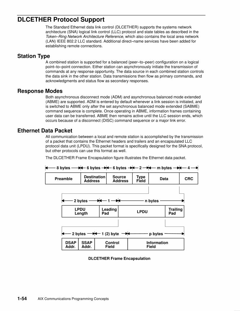
1-54 AIX Communications Programming Concepts
DLCETHER Protocol Support The Standard Ethernet data link control (DLCETHER) supports the systems networkarchitecture (SNA) logical link control (LLC) protocol and state tables as described in theToken–Ring Network Architecture Reference, which also contains the local area network(LAN) IEEE 802.2 LLC standard. Additional direct–name services have been added forestablishing remote connections.
Station TypeA combined station is supported for a balanced (peer–to–peer) configuration on a logicalpoint–to–point connection. Either station can asynchronously initiate the transmission ofcommands at any response opportunity. The data source in each combined station controlsthe data sink in the other station. Data transmissions then flow as primary commands, andacknowledgments and status flow as secondary responses.
Response ModesBoth asynchronous disconnect mode (ADM) and asynchronous balanced mode extended(ABME) are supported. ADM is entered by default whenever a link session is initiated, andis switched to ABME only after the set asynchronous balanced mode extended (SABME)command sequence is complete. Once operating in ABME, information frames containinguser data can be transferred. ABME then remains active until the LLC session ends, whichoccurs because of a disconnect (DISC) command sequence or a major link error.
Ethernet Data PacketAll communication between a local and remote station is accomplished by the transmissionof a packet that contains the Ethernet headers and trailers and an encapsulated LLCprotocol data unit (LPDU). This packet format is specifically designed for the SNA protocol,but other protocols can use this format as well.
The DLCETHER Frame Encapsulation figure illustrates the Ethernet data packet.
DSAPAddr.
SSAPAddr.
ControlField
InformationField
2 bytes p bytes1 (2) byte
LeadingPad
TrailingPadLPDU
LPDULength
2 bytes n bytes
DestinationAddress
SourceAddress
TypeField
Preamble Data CRC
8 bytes 6 bytes 6 bytes m bytes2 4
1
DLCETHER Frame Encapsulation

Data Link Control 1-55
The Ethernet data packet consists of the following:
LPDU LLC protocol data unit
DSAP Destination service access point (SAP) address field
SSAP Source SAP address field
CRC Cyclic redundancy check or frame–check sequence
m bytes Integer value greater than or equal to 46 and less than or equal to 1500
n bytes Integer value greater than or equal to 43 and less than or equal to 1497
p bytes Integer value greater than or equal to 0 and less than or equal to 1493
Note: The Preamble and CRC identify both of these as something that is added anddeleted by the hardware adapter.

1-56 AIX Communications Programming Concepts
DLCETHER Name–Discovery Services In addition to the standard IEEE 802.2 Common Logical Link Protocol support and addressresolution services, Standard Ethernet data link control (DLCETHER) also provides aname–discovery service that allows the operator to identify local and remote stations byname instead of by six–byte physical addresses. Each port must have a unique name onthe network of up to 20 characters. The character set used varies depending on the user’sprotocol. Systems network architecture (SNA), for example, requires character set A.Additionally, each new service access point (SAP) supported on a particular port can have aunique name if desired.
Each name is added to the network by broadcasting a find (local name) request when thenew name is being introduced to a given network port. If no response other than an echoresults from the find (local name) request, after sending it the number of times specified, thephysical link is declared opened, and the name is assigned to the local port and SAP. Ifanother port on the network has already added the name, a name found response is sent tothe station that issued the find request. A result code (DLC_NAME_IN_USE) indicates thatthe new attachment was unsuccessful and that a different name must be chosen. Calls areestablished by broadcasting a find (remote name) request to the network and waiting for aresponse from the port with the specified name. Only those ports that have listenattachments pending receive colliding find requests or are already attached to therequesting remote station answer a find request.
LAN Find Data FormatFind Header
0–1 Byte length of the find packet including the length field
2–3 Key 0x0001
4–n Remaining control vectors
Target Name
0–1 Vector length = 0x000F to 0x0022
2–3 Key 0x0004
4–9 Name structure architecture ID:
4–5 Subvector length = 0x0006
6–7 Key 0x4011
8–9 Identifier = 0x8000 (locally administered)
10–m Object name:
10–11 Subvector length = 0x0005 to 0x000C
12–13 Key 0x4010
14–m Target name (1 to 20 bytes)

Data Link Control 1-57
Source Name
0–1 Vector length = 0x000F to 0x0022
2–3 Key 0x000D
4–9 Name structure architecture ID:
4–5 Subvector length = 0x0006
6–7 Key 0x4011
8–9 Identifier = 0x8000 (locally administered)
10–p Object name:
10–11 Subvector length = 0x0005 to 0x000C
12–13 Key 0x4010
14–p Source name (1 to 20 bytes)
Correlator
0–1 Vector length = 0x0008
2–3 Key 0x4003
4–7 Correlator value:
Byte 4 Bit 0 1 represents a SAP correlator for a find (self)
Byte 4 Bit 0 0 represents a link station (LS) correlator for a find(remote)
Source Medium Access Control (MAC) Address
0–1 Vector length = 0x000A
2–3 Key 0x4006
4–9 Source MAC address (6 bytes).
Source SAP
0–1 Vector length = 0x0005
2–3 Key 0x4007
4 Source SAP address
LAN Found Data FormatFound Header
0–1 Byte length of the found packet including the length field
2–3 Key 0x0002
4–n Remaining control vectors
Correlator
0–1 Vector length = 0x0008
2–3 Key 0x4003
4–7 Correlator value:
Byte 4 Bit 0 1 represents a SAP correlator for a find (self)
Byte 4 Bit 0 0 represents an LS correlator for a find (remote)

1-58 AIX Communications Programming Concepts
Source MAC Address
0–1 Vector length = 0x000A
2–3 Key 0x4006
4–9 Source MAC address (6 bytes)
Source SAP
0–1 Vector length = 0x0005
2–3 Key 0x4007
4 Source SAP address
Response Code
0–1 Vector length = 0x0005
2–3 Key 0x400B
4 Response code:
B’0xxx xxxx’ Positive response
B’0000 0001’ Resources available
B’1xxx xxxx’ Negative response
B’1000 0001’ Insufficient resources

Data Link Control 1-59
DLCETHER Direct Network Services Some users wish to handle their own unnumbered information packets on the networkwithout the aid of the data link layer within the Standard Ethernet Data Link Control(DLCETHER). This decision results in protocol constraints from their individual serviceaccess points (SAPs). A direct network interface is provided that allows an entire packet tobe generated and sent by a user once the user SAP has been opened. This provisionallows full control of every field in the data link header for each write issued. Also provided isthe ability to view the entire packet contents on received frames.
The criteria for a direct network write require that:
• The local SAP must be valid and open.
• The data link control byte must indicate unnumbered information (0x03).

1-60 AIX Communications Programming Concepts
DLCETHER Connection Contention Dual paths to the same nodes are detected by the Standard Ethernet Data Link Control(DLCETHER) device manager in one of two ways. First, if a call is in progress to a remotenode that is also trying to call the local node, the incoming find (remote name) request istreated as if a local listen were outstanding. Second, if a pending local listen has beenacquired by a remote node call and the local user issues a call to that remote node after thelink session is already active, a result code (DLC_REMOTE_CONN) is returned to the useralong with the link station correlator of the attachment already active. This allows the user torelink attachment pointers.

Data Link Control 1-61
DLCETHER Link Session Initiation Standard Ethernet data link control (DLCETHER) is initialized at the open link station as acombined station in asynchronous disconnect mode (ADM). As a secondary or combinedstation, DLCETHER is in a receive state waiting for a command frame from the primary orcombined station. The following command frames are accepted by the secondary orcombined station at this time:
SABME Set asynchronous balanced mode extended
XID Exchange station identification
TEST Test link
UI Unnumbered information – datagram
DISC Disconnect
Any other command frame is ignored. Once a SABME command frame is received, thestation is ready for normal data transfer, and the following frames are also accepted:
I Information
RR Receive ready
RNR Receive not ready
REJ Reject
As a primary or combined station, DLCETHER can perform ADM XID, ADM TESTexchanges, send datagrams, or connect the remote into the asynchronous balanced modeextended (ABME) command frame. XID exchanges allow the primary or combined station tosend out its station–specific identification to the secondary or combined station and obtain aresponse. Once an XID response is received, any attached information field is passed to theuser for further action.
The TEST exchanges allow the primary or combined station to send out a buffer ofinformation that is echoed by the secondary or combined station to test the integrity of thelink.
Initiation of the normal data exchange mode, ABME, causes the primary or combinedstation to send a SABME command frame to the secondary or combined station. Once sentsuccessfully, the connection is said to be contacted, and the user is notified. I–frames cannow be sent and received between the linked stations.

1-62 AIX Communications Programming Concepts
DLCETHER Link Session Termination The Standard Ethernet data link control (DLCETHER) device manager can be terminated bythe user or by the remote station in the following ways:
• Issuing a DLC_HALT_LS command operation to the DLCETHER device manager willcause the primary/combined station to initiate a disconnect (DISC) command packetsequence.
• Receiving an inactivity time out can terminate a DLCETHER link session. This action isuseful in detecting a loss of connection in the middle of a session.
• Sending a DISC command packet as a primary combined station will terminate aDLCETHER link session.
Note: Abnormal termination is caused by certain protocol violations or by resourceoutages.

Data Link Control 1-63
DLCETHER Programming Interfaces The Standard Ethernet data link control (DLCETHER) conforms to the generic data linkcontrol (GDLC) guidelines except as follows:
Note: The dlc prefix is replaced with the edl prefix for the DLCETHER device manager.
edlclose DLCETHER is fully compatible with the dlcclose GDLC interface.
edlconfig DLCETHER is fully compatible with the dlcconfig GDLC interface. Noinitialization parameters are required.
edlmpx DLCETHER is fully compatible with the dlcmpx GDLC interface.
edlopen DLCETHER is fully compatible with the dlcopen GDLC interface.
edlread DLCETHER is compatible with the dlcread GDLC interface with the followingconditions:
• The readx subroutines can have DLCETHER data link header informationprefixed to the I–field being passed to the application. This is optionalbased on the readx subroutine data link header length extensionparameter in the gdl_io_ext structure.
• If this field is nonzero, DLCETHER copies the data link header and theI–field to user space and sets the actual length of the data link header intothe length field.
• If the field is 0, no data link header information is copied to user space.See the DLCETHER frame encapsulation on page 1-54 for more details.
The following kernel receive packet subroutines always have the DLCETHER data linkheader information within the communications memory buffer (mbuf) and can locate it bysubtracting the length passed (in the gdl_io_ext structure) from the data offset field of thembuf structure.
edlselect DLCETHER is fully compatible with the dlcselect GDLC interface.
edlwrite DLCETHER is compatible with the dlcwrite GDLC interface with theexception that network data can only be written as an unnumberedinformation (UI) packet and must have the complete data link headerprefixed to the data. DLCETHER verifies that the local (source) serviceaccess point (SAP) is enabled and that the control byte is UI (0x03). See theDLCETHER Frame Encapsulation figure on page 1-54 for more details.
edlioctl DLCETHER is compatible with the dlcioctl GDLC interface with conditionson these operations (described in the following sections):
• DLC_ENABLE_SAP
• DLC_START_LS
• DLC_ALTER
• DLC_QUERY_SAP
• DLC_QUERY_LS
• DLC_ENTER_SHOLD
• DLC_EXIT_SHOLD
• DLC_ADD_GRP
• DLC_ADD_FUNC_ADDR
• DLC_DEL_FUNC_ADDR
• DLC_DEL_GRP
• IOCINFO
1-64 AIX Communications Programming Concepts
DLC_ENABLE_SAPThe ioctl subroutine argument structure for enabling a SAP (dlc_esap_arg) has thefollowing specifics:
• The grp_addr field is a 6–byte value as specified in the draft IEEE Standard 802.3specifications. Octet grp_addr[0] specifies the most significant byte and octet grp_addr[5]specifies the least significant byte. Each octet of the address field is transmitted, leastsignificant bit first. Group addresses sometimes are called multicast addresses. Anexample of an group address follows:
0x0900_2B00_0004
Note: No checks are made by the DLCETHER device manager as to whether a receivedpacket was accepted by the adapter due to a preset network address or group address.
• The max_ls (maximum link station) field cannot exceed 255 bytes.
• The following common SAP flags are not supported:
ENCD Indicates a synchronous data link control (SDLC) serial encoding.
NTWK Indicates a teleprocessing network type.
LINK Indicates a teleprocessing link type.
PHYC Indicates a physical network call (teleprocessing).
ANSW Indicates a teleprocessing autocall and autoanswer.
• Group SAPs are not supported, so the num_grp_saps (number of group SAPs) field mustbe set to 0.
• The laddr_name (local address and name) field and its associated length are only usedfor name discovery when the common SAP flag ADDR field is set to 0. When resolveprocedures are used (that is, the ADDR flag is set to 1), DLCETHER obtains the localnetwork address from the device handler and not from the dlc_esap_arg structure.
• The local_sap (local service access point) field can be set to any value except the nullSAP (0x00) or the name–discovery SAP (0xFC). Also, the low–order bit must be set to 0(B‘nnnnnnn0’) to indicate an individual address.
• No protocol–specific data area is required for the DLCETHER device manager to enablea SAP.
DLC_START_LSThe ioctl subroutine argument structure for starting a link station (dlc_sls_arg) has thefollowing specifics:
• These common link station flags are not supported:
STAT Indicates a station type for SDLC.
NEGO Indicates a negotiable station type for SDLC.
• The raddr_name (remote address or name) field is used only for outgoing calls when theDLC_SLS_LSVC common link station flag is active.
• The maxif (maximum I–field) length can be set to any value greater than 0. See the frameformat figure on page 1-54 for supported byte lengths. The DLCETHER device manageradjusts this value to a maximum of 1493 bytes if set too large.
• The rcv_wind (receive window) field can be set to any value between 1 and 127,inclusive. The recommended value is 127.
• The xmit_wind (transmit window) field can be set to any value between 1 and 127,inclusive. The recommended value is 26.

Data Link Control 1-65
• The rsap (remote SAP) field can be set to any value except null SAP (0x00) or thename–discovery SAP (0xFC). Also, the low–order bit must be set to 0 (B‘nnnnnnn0’) toindicate an individual address.
• The max_repoll field can be set to any value between 1 and 255, inclusive. Therecommended value is 8.
• The repoll_time field is defined in increments of 0.5 seconds and can be set to any valuebetween 1 and 255, inclusive. The recommended value is 2, giving a time–out duration of1 to 1.5 seconds.
• The ack_time (acknowledgment time) field is defined in increments of 0.5 seconds andcan be set to any value between 1 and 255, inclusive. The recommended value is 1,giving a time–out duration of 0.5 to 1 second.
• The inact_time (inactivity time) field is defined in increments of 1 second, and can be setto any value between 1 and 255, inclusive. The recommended value is 48, giving atime–out duration of 48 to 48.5 seconds.
• The force_time (force halt time) field is defined in increments of 1 second, and can be setto any value between 1 and 16383, inclusive. The recommended value is 120, giving atime–out duration of approximately 2 minutes.
• No protocol–specific data area is required for the DLCETHER device manager to start alink station.
DLC_ALTERThe ioctl subroutine argument structure for altering a link station (dlc_alter_arg) has thefollowing specifics:
• These alter flags are not supported:
RTE Alters routing.
SM1, SM2 Sets synchronous data link control (SDLC) control mode.
• No protocol–specific data area is required for the DLCETHER device manager to alter alink station.
DLC_QUERY_SAPThe device driver–dependent data returned from DLCETHER for this ioctl operation is theent_ndd_stats_t structure defined in the /usr/include/sys/cdli_entuser.h file.
DLC_QUERY_LSNo protocol–specific data area is supported by DLCETHER for this ioctl operation.
DLC_ENTER_SHOLDThe enter_short_hold option is not supported by the DLCETHER device manager.
DLC_EXIT_SHOLDThe exit_short_hold option is not supported by the DLCETHER device manager.
DLC_ADD_GRPThe add_group or multicast address option is supported by the DLCETHER devicemanager as a six–byte value as described above in DLC_ENABLE_SAP (group address)ioctl operation.

1-66 AIX Communications Programming Concepts
DLC_ADD_FUNC_ADDRThe add_functional_address option is not supported by DLCETHER.
DLC_DEL_FUNC_ADDRThe delete_functional_address option is not supported by DLCETHER.
DLC_DEL_GRPThe delete group or multicast option is supported by the DLCETHER device manager. Theaddress being removed must match an address that was added with a DLC_ENABLE_SAPor DLC_ADD_GRP ioctl operation.
IOCINFOThe ioctype variable returned is defined as DD_DLC definition and the subtype returned isDS_DLCETHER.

Data Link Control 1-67
Synchronous Data Link Control Overview Synchronous data link control (DLCSDLC) is one of the generic data link controls. Itprovides an access procedure for transparent and code–independent informationinterchange across teleprocessing and data networks, as defined in the SDLC Conceptsdocument.
The list of architecture supported by DLCSDLC includes:
• Normal disconnected mode (NDM) and normal response mode (NRM)
• Two–way alternate (half–duplex) data flow
• Secondary station point–to–point, multipoint, and multi–multipoint configurations
• Primary station point–to–point and multipoint configurations
• Modulo 8 transmit–and–receive sequence counts
• Nonextended (single–byte) station address.
For more information about DLCSDLC controls, see:
• DLCSDLC Device Manager Functions, on page 1-68
• DLCSDLC Protocol Support, on page 1-69
• DLCSDLC Programming Interfaces, on page 1-73
• DLCSDLC Asynchronous Function Subroutine Calls, on page 1-78.

1-68 AIX Communications Programming Concepts
DLCSDLC Device Manager Functions Synchronous data link control (SDLC) is split between a physical adapter with its associateddevice handler and a data link control (DLC) component. The synchronous data link control(DLCSDLC) device manager is responsible for functions that include:
• Sequencing information frames
• Creating address and control for transmit frames
• Servicing control for receive frames
• Handling repoll and inactivity time outs
• Generating frame–rejects
• Handling transmit windows
• Handling reliability counters, availability counters, serviceability counters, error logs, andlink traces.
The device handler and adapter are jointly responsible for the remaining SDLC functions:
• Recognizing station addresses
• Encoding and decoding non–return–to–zero (inverted) recording (NRZI) andnon–return–to–zero (NRZ)
• Inserting and deleting 0 bits
• Generating and checking frame–check sequences
• Generating and checking flags and pads
• Filling interframe time
• Handling line–attachment protocols, such as RS–232C, X.21, and Smartmodem
• Handling fail–safe time outs
• Handling autoresponse for nonproductive supervisory command frames.
Data Link Control 1-69
DLCSDLC Protocol Support The synchronous data link control (SDLC) device manager (DLCSDLC) supports SDLCprotocol and state tables.
Station TypesDLCSDLC supports two station types:
• Primary stations responsible for control of data interchange on the link
• Secondary, or subordinate, stations on the link
Operation ModesDLCSDLC supports two modes of operation:
• Single–physical unit (PU) mode
• Multiple–PU mode
Single–PU mode allows a single open per port. In this mode, only one DLC_ENABLE_SAPioctl operation is allowed per port. All additional DLC_ENABLE_SAP ioctl operations arerejected with an errno value of EINVAL. In addition, only one file descriptor can be used toissue read, write, and ioctl operations. When multiple applications wish to use the sameport, only one application can obtain the file descriptor, making it difficult to share the port.
SDLC multiple–PU secondary support allows multiple secondary stations (up to 254) tooccupy a single physical port, and operate concurrently by multiplexing on the single–bytelink–station address field found in each receive packet. Multiple–PU support also allowsmultiple applications to issue opens and DLC_ENABLE_SAP and DLC_START_LS ioctloperations on the same physical port, independent of other applications on that port.
For migration purposes, multiple–PU support is activated only if the first open per port to the/dev/dlcsdlc file is extended with the dlc_open_ext structure and the maxsaps (maximumservice access points) field is set to a value between 2 and 127, inclusive. This type of openoperation allows DLCSDLC to switch from the original single–PU operation to multiple–PUoperation. Only secondary link stations are allowed to be started in multiple–PU mode.
One channel owns the service access point (SAP) on a single port since a single networkconfiguration is supported for each port. However, subsequent DCL_ENABLE_SAP ioctloperations issued when the port is already activated fail with an errno value of EBUSYinstead of EINVAL. The current SAP correlator value (gdlc_sap_corr) is returned on theseEBUSY conditions, enabling subsequent commands to be issued to DLCSDLC, eventhough a different user process may own the SAP.
Any address between 0x01 and 0xFE may be specified as the local secondary link stationaddress. Secondary station address 0x00 is not valid. Station address 0xFF is reserved forbroadcast communication. Any packets received with address 0xFF are passed to a singleactive link station for subsequent response on a port. Any additional active link stations onthat port do not receive the packet.
1-70 AIX Communications Programming Concepts
Transmission FramesAll communication between the local and remote stations is accomplished by thetransmission of frames. The SDLC frame format consists of:
Unique flag sequence (B‘01111110’) 1 byte
Station link address field 1 byte
Control field 1 byte
Information field n bytes
Frame check sequence 2 bytes
Unique flag sequence (B‘01111110’) 1 byte
Three kinds of SDLC frames exist: information, supervisory, and unnumbered. Informationframes transport sequenced user data between the local and remote stations. Supervisoryframes carry control parameters relative to the sequenced data transfer. Unnumberedframes transport the controls relative to nonsequenced transfers.
Response ModesBoth normal disconnect mode (NDM) and normal response mode (NRM) are supported.NDM is entered by default whenever a session is initiated, and is switched to NRM onlyafter completion of the set normal response mode/unnumbered acknowledge (SNRM/UA)command sequence. Once operating in NRM, information frames containing user data canbe transferred. NRM then remains active until termination of the SDLC session, whichoccurs due to the disconnect/unnumbered acknowledge (DISC/UA) command sequence ora major link error. Once termination is complete, SDLC activity halts, and the NDM/NRMmodes are not re–entered until another session is initiated.
Station Link Address FieldThe supported station link address field is nonextended and consists of either theall–stations (broadcast) address or a single unique 8–bit value other than the all–zeros (null)address. The secondary station’s address can be any value from 1 through 254. Addressvalue 255 (broadcast) is only used by the primary station for initial contact of apoint–to–point secondary station type, where the secondary’s address is unknown. Oncecontact has been made, the secondary station’s returned address is used exclusively for theremainder of the session.
Data Link Control 1-71
Control Field (Commands Supported)All commands are generated by the primary station for the secondary station. Eachcommand carries the poll indicator to request immediate response, except when sendingmultiple information frames. Information frames that are concatenated have the pollindicator turned on in the last frame of the burst. The commands supported are:
Information Sends sequenced user data from the primary station tothe secondary station, and acknowledges any receivedinformation frames.
Receive Ready Indicates that receive storage is available andacknowledges any received information frames. Thisreceive ready command is a supervisory command.
Receive Not Ready Indicates receive storage is not available andacknowledges any received information frames. Thereceive not ready command is a supervisory command.
Disconnect Requests the logical and physical disconnection of thelink. The disconnect command is an unnumberedcommand.
Set Normal Response Mode Requests entry into normal response mode and resets theinformation sequence counts. The setnormal responsemode command is an unnumbered command.
Test Solicits an echoed TEST response from the secondarystation and can carry an optional information field. Thetest command is an unnumbered command.
Exchange StationIdentification
Solicits an exchange identification (XID) response thatcontains either the station identification of the secondarystation or link negotiation information that allows thealteration of the primary or secondary relationship by theuser. The exchange station identification command isan unnumbered command.
Control Field (Responses Supported)All responses are generated by the secondary station for the primary station. Eachresponse carries the final indicator to specify send completion, except when sendingmultiple information frames. Information frames that are concatenated have the finalindicator on in the last frame of the burst. The responses supported are:
Information Sends sequenced user data from the secondary station tothe primary station. It also acknowledges any receivedinformation frames.
Receive Ready Indicates receive storage is available and acknowledgesany received information frames. The receive readyresponse is a supervisory response.
Receive Not Ready Indicates receive storage is not available andacknowledges any received information frames. Thereceive not ready response is a supervisory response.
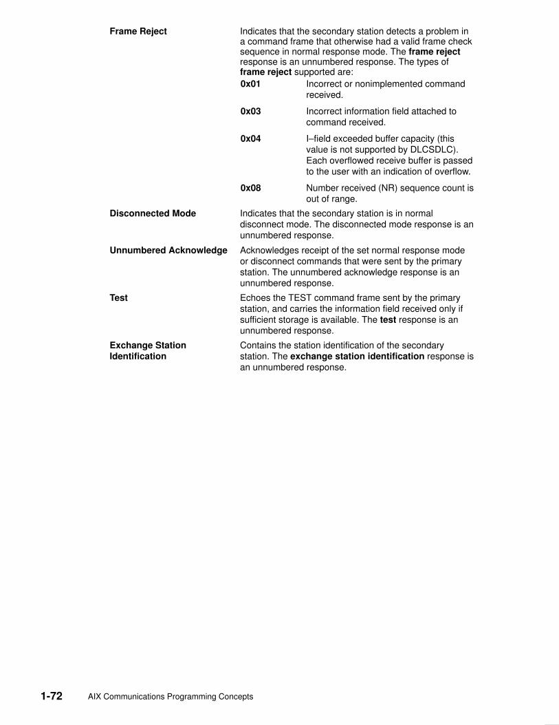
1-72 AIX Communications Programming Concepts
Frame Reject Indicates that the secondary station detects a problem ina command frame that otherwise had a valid frame checksequence in normal response mode. The frame rejectresponse is an unnumbered response. The types offrame reject supported are:
0x01 Incorrect or nonimplemented commandreceived.
0x03 Incorrect information field attached tocommand received.
0x04 I–field exceeded buffer capacity (thisvalue is not supported by DLCSDLC).Each overflowed receive buffer is passedto the user with an indication of overflow.
0x08 Number received (NR) sequence count isout of range.
Disconnected Mode Indicates that the secondary station is in normaldisconnect mode. The disconnected mode response is anunnumbered response.
Unnumbered Acknowledge Acknowledges receipt of the set normal response modeor disconnect commands that were sent by the primarystation. The unnumbered acknowledge response is anunnumbered response.
Test Echoes the TEST command frame sent by the primarystation, and carries the information field received only ifsufficient storage is available. The test response is anunnumbered response.
Exchange StationIdentification
Contains the station identification of the secondarystation. The exchange station identification response isan unnumbered response.

Data Link Control 1-73
DLCSDLC Programming Interfaces The synchronous data link control (SDLC) device manager (DLCSDLC) conforms to thegeneric data link control (GDLC) guidelines except where noted in the following list.Additional structures and definitions for DLCSDLC can be found in the/usr/include/sys/sdlextcb.h file.
Note: The GDLC entry–point prefix dlc is replaced with the sdl prefix to denote DLCSDLCdevice manager operation.
sdlclose DLCSDLC is fully compatible with the dlcclose GDLC interface.
sdlconfig DLCSDLC is fully compatible with the dlcconfig GDLC interface. Noinitialization parameters are required.
sdlmpx DLCSDLC is fully compatible with the dlcmpx GDLC interface.
sdlopen DLCSDLC is fully compatible with the dlcopen GDLC interface with thefollowing conditions:
• Single–physical unit (PU) mode allows only one open per port. Theopen can come from either an application or kernel user, but multipleusers cannot share the same port. Single–PU mode is entered byissuing the open without an extension, or by issuing an extended openwith the maxsaps (maximum service access points) field set to a valueof 0 or 1. Single–PU mode is the default.
• Multiple–PU mode allows multiple processes to open a secondary port.Multiple–PU mode is entered by issuing an extended open with themaxsaps field set to a value greater than 1.
Note: Only one user process is allowed to open a primary port.
sdlread DLCSDLC is compatible with the dlcread GDLC interface, with thefollowing conditions:
• Network data is defined as any data received from data communicationequipment (DCE) that is not specific to the SDLC session protocol.Examples are X.21 call–progress signals or Smartmodemcall–establishment messages. This data must be interpreted differently,depending on the physical attachment in use.
• Datagram receive data is not supported.
sdlselect DLCSDLC is fully compatible with the dlcselect GDLC interface.

1-74 AIX Communications Programming Concepts
sdlwrite DLCSDLC is compatible with the dlcwrite GDLC interface, with theexception that network data and datagram data are not supported in thesend direction. Network data such as X.21 or Smartmodemcall–establishment data is sent using the DLC_ENABLE_SAP ioctloperation.
sdlioctl DLCSDLC is compatible with the dlcioctl GDLC interface, with conditionson the following operations:
• DLC_ENABLE_SAP
• DLC_START_LS
• DLC_ALTER
• DLC_QUERY_SAP
• DLC_QUERY_LS
• DLC_ENTER_SHOLD
• DLC_EXIT_SHOLD
• DLC_ADD_GRP
• DLC_ADD_FUNC_ADDR
• DLC_DEL_FUNC_ADDR
• IOCINFO
The following sections describe these conditions.
DLC_ENABLE_SAPDLCSDLC supports two modes of operation:
• Single–PU mode is entered through the open to DLCSDLC. In this mode, only oneDLC_ENABLE_SAP ioctl operation is allowed per port. All additionalDLC_ENABLE_SAP ioctl operations are rejected with an errno value of EINVAL.
• Multiple–PU mode is also entered through the open to DLCSDLC. In this mode, up to 254DLC_ENABLE_SAP ioctl operations can be issued. The first DLC_ENABLE_SAP ioctloperation establishes the physical connection. All subsequent DLC_ENABLE_SAP ioctlsreturn an errno value of EBUSY, but pass back the gdlc_sap_corr value of the firstsuccessful DLC_ENABLE_SAP so that link stations can be started.
The ioctl subroutine argument structure for enabling a service access point (SAP)(dlc_esap_arg) has the following specifics:
• The func_addr_mask (function address mask) field is not supported.
• The grp_addr (group address) field is not supported.
• The max_ls (maximum link stations) field cannot exceed a value of 254 on a multidropprimary link or a multiple–PU secondary link, and cannot exceed 1 on a point–to–pointlink.
• The following common SAP flag is not supported:
ADDR Specifies local address or name indicator.
• The laddr_name (local address or name) field is not supported, so the length of the localaddress/name field is ignored.
• Group SAPs are not supported, so the num_grp_saps (number of group SAPs) andgrp_sap (group SAP – n) fields are ignored.
• The local_sap (local service access point) field is not supported and is ignored.

Data Link Control 1-75
• The protocol specific data area is identical to the start device structure required by themultiprotocol device handler. See the /usr/include/sys/mpqp.h file and the t_start_devstructure for more details.
DLC_START_LSDLCSDLC supports up to 254 concurrent link stations (LSs) on a single port when itoperates as a multidrop primary node or a multiple–PU secondary node. Only one LS canbe started when DLCSDLC operates on a point–to–point connection, or when it is asingle–PU secondary node on a multidrop connection.
• The following common link station flags are not supported:
LSVC LS virtual call is ignored.
ADDR Address indicator must be set to 1 to indicate that no name–discoveryservices are provided.
• The len_raddr_name (length of remote address or name) field must be set to 1.
• The raddr_name (remote address or name) field is the one–byte station address of theremote node in hexadecimal.
• The maxif (maximum I–field length) field can be set to any value greater than 0.DLCSDLC adjusts this value to a maximum of 4094 bytes if set too large.
• The rcv_wind (maximum receive window) field can be set to any value from 1 to 7. Therecommended value is 7.
• The xmit_wind (maximum transmit window) field can be set to any value from 1 to 7. Therecommended value is 7.
• The rsap (remote SAP) field is ignored.
• The rsap_low (remote SAP low range) field is ignored.
• The rsap_high (remote SAP high range) field is ignored.
• The max_repoll field can be set to any value from 1 to 255, inclusive. The recommendedvalue is 15.
• The repoll_time field is defined in increments of 0.1 second and can be set to any valuefrom 1 to 255. The recommended value is 30, giving a time–out duration of approximately30 seconds.
• The ack_time (acknowledgment time) field is ignored.
• The inact_time (inactivity time) field is defined in increments of 1 second and can be setto any value from 1 to 255, inclusive. The recommended value is 30, giving a time–outduration of approximately 30 seconds.
• The force_time (force halt time) field is defined in increments of 1 second and can be setto any value from 1 to 16383, inclusive. The recommended value is 120, giving atime–out duration of approximately 2 minutes.
• The following protocol–specific data area must be appended to the generic start LSargument structure (dlc_sls_arg). This structure provides DLCSDLC with additionalprotocol–specific configuration parameters:
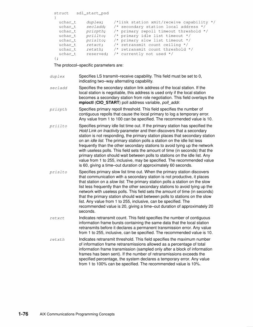
1-76 AIX Communications Programming Concepts
struct sdl_start_psd
}
uchar_t duplex; /*link station xmit/receive capability */
uchar_t secladd; /* secondary station local address */
uchar_t prirpth; /* primary repoll timeout threshold */
uchar_t priilto; /* primary idle list timeout */
uchar_t prislto; /* primary slow list timeout */
uchar_t retxct; /* retransmit count ceiling */
uchar_t retxth; /* retransmit count threshold */
uchar_t reserved; /* currently not used */
{;
The protocol–specific parameters are:
duplex Specifies LS transmit–receive capability. This field must be set to 0,indicating two–way alternating capability.
secladd Specifies the secondary station link address of the local station. If thelocal station is negotiable, this address is used only if the local stationbecomes a secondary station from role negotiation. This field overlays thempioctl (CIO_START) poll address variable, poll_addr.
prirpth Specifies primary repoll threshold. This field specifies the number ofcontiguous repolls that cause the local primary to log a temporary error.Any value from 1 to 100 can be specified. The recommended value is 10.
priilto Specifies primary idle list time out. If the primary station has specified theHold Link on Inactivity parameter and then discovers that a secondarystation is not responding, the primary station places that secondary stationon an idle list. The primary station polls a station on the idle list lessfrequently than the other secondary stations to avoid tying up the networkwith useless polls. This field sets the amount of time (in seconds) that theprimary station should wait between polls to stations on the idle list. Anyvalue from 1 to 255, inclusive, may be specified. The recommended valueis 60, giving a time–out duration of approximately 60 seconds.
prislto Specifies primary slow list time out. When the primary station discoversthat communication with a secondary station is not productive, it placesthat station on a slow list. The primary station polls a station on the slowlist less frequently than the other secondary stations to avoid tying up thenetwork with useless polls. This field sets the amount of time (in seconds)that the primary station should wait between polls to stations on the slowlist. Any value from 1 to 255, inclusive, can be specified. Therecommended value is 20, giving a time–out duration of approximately 20seconds.
retxct Indicates retransmit count. This field specifies the number of contiguousinformation frame bursts containing the same data that the local stationretransmits before it declares a permanent transmission error. Any valuefrom 1 to 255, inclusive, can be specified. The recommended value is 10.
retxth Indicates retransmit threshold. This field specifies the maximum numberof information frame retransmissions allowed as a percentage of totalinformation frame transmission (sampled only after a block of informationframes has been sent). If the number of retransmissions exceeds thespecified percentage, the system declares a temporary error. Any valuefrom 1 to 100% can be specified. The recommended value is 10%.

Data Link Control 1-77
DLC_ALTERSpecifics for the ioctl subroutine argument structure to alter a link station (dlc_alter_arg)include:
• These alter flags are not supported:
AKT Alter acknowledgment time out.
RTE Alter routing.
• The act_time (acknowledge time out) field is ignored.
• The routing data field is ignored.
• No protocol–specific data area is required for DLCSDLC to alter its configuration.
DLC_QUERY_SAPNo device driver–dependent data area is supported by DLCSDLC for the query sap ioctloperation.
DLC_QUERY_LSNo protocol–specific data area is supported by DLCSDLC for the query link station ioctloperation.
DLC_ENTER_SHOLDDLCSDLC does not currently support the enter_short_hold option.
DLC_EXIT_SHOLDDLCSDLC does not currently support the exit_short_hold option.
DLC_ADD_GRPThe add_group or multicast address option is not supported by DLCSDLC.
DLC_ADD_FUNC_ADDRThe add_functional_address option is not supported by DLCSDLC.
DLC_DEL_FUNC_ADDRThe delete_functional_address option is not supported by DLCSDLC.
IOCINFOThe ioctype variable is defined as a DD_DLC definition and the subtype returned isDS_DLCSDLC.

1-78 AIX Communications Programming Concepts
DLCSDLC Asynchronous Function Subroutine Calls Datagram data received is not supported, and the synchronous data link control (SDLC)device manager (DLCSDLC) never calls the rcvd_fa function.
DLCSDLC is compatible with each of the other asynchronous function subroutines for thekernel user.

Data Link Control 1-79
Qualified Logical Link Control (DLCQLLC) Overview Qualified logical link control (QLLC) data link control (DLCQLLC) is one of the generic datalink controls. It provides an access procedure to attach to X.25 packet–switching networks.
DLCQLLC fully supports the 1980 and 1984 versions of the CCITT recommendationrelevant to Systems Network Architecture (SNA)–to–SNA connections. It allowspoint–to–point connections over an X.25 network between a pair of primary and secondarylink stations.
DLCQLLC provides two–way alternate (half–duplex) data flow over switched or permanentvirtual circuits.
For more information about the DLCQLLC controls, see:
• DLCQLLC Device Manager Functions, on page 1-79
• DLCQLLC Programming Interfaces, on page 1-80
• DLCQLLC Asynchronous Function Subroutine Calls, on page 1-85
DLCQLLC supports the following X.25 optional facilities:
• Modulo 8/128 packet sequence numbering
• Closed user groups
• Recognized private operating agencies
• Network user identification
• Reverse charging
• Packet–size negotiation
• Window–size negotiation
• Throughput class negotiation
DLCQLLC Device Manager Functions DLCQLLC, as described in the X.25 Interface for Attaching SNA Nodes to Packet–SwitchData Networks and X.25 1984 Interface Architectural Reference, is split between a physicaladapter with its associated device handler and a data link control component. The DLCcomponent is responsible for the following QLLC functions:
• Creation of address and control for transmit frames
• Service of control for receive frames
• Repoll and inactivity time outs
• Frame–reject generation
• Facility negotiation
The data link control and device handler components are jointly responsible for:
• Establishment of an X.25 virtual circuit
• Clearing of an X.25 virtual circuit
• Notification of exceptional conditions to higher levels
• Reliability/availability/serviceability (RAS) counters, error logs, and link traces
The device handler and adapter are jointly responsible for:
• Packetization of I–frames
• Packet sequencing
• Link access protocol balance (LAPB) procedures as defined by CCITT recommendationX.25
• Physical–line attachment protocols

1-80 AIX Communications Programming Concepts
DLCQLLC Programming Interfaces QLLC data link control (DLCQLLC) conforms to the GDLC guidelines except where notedbelow.
Note: The dlc prefix is replaced with qlc prefix for DLCQLLC device manager.
qlcclose DLCQLLC is fully compatible with the dlcclose GDLC interface.
qlcconfig DLCQLLC is fully compatible with the dlcconfig GDLC interface. Noinitialization parameters are required.
qlcmpx DLCQLLC is fully compatible with the dlcmpx GDLC interface.
qlcopen DLCQLLC is fully compatible with the dlcopen GDLC interface.
qlcread DLCQLLC is compatible with the dlcread GDLC interface, except thatnetwork data and datagram receive data are not supported.
qlcselect DLCQLLC is fully compatible with the dlcselect GDLC interface.
qlcwrite DLCQLLC is compatible with the dlcwrite GDLC interface with theexception that network data and datagram data are not supported.
qlcioctl DLCQLLC is compatible with the dlcioctl GDLC interface with conditionson the following operations:
• DLC_ENABLE_SAP
• DLC_START_LS
• DLC_ALTER
• DLC_QUERY_SAP
• DLC_QUERY_LS
• DLC_ENTER_SHOLD
• DLC_EXIT_SHOLD
• DLC_ADD_GRP
• DLC_ADD_FUNC_ADDR
• DLC_DEL_FUNC_ADDR
• IOCINFO
The following sections describe these conditions.
DLC_ENABLE_SAPThe ioctl subroutine argument structure for enabling a service access point (SAP),dlc_esap_arg, has the following specifics:
• The function address mask field is not supported.
• The group address field is not supported.
• The max_ls field cannot exceed a value of 255.
• The common SAP flags are not supported.
• Group SAPs are not supported, so the number of group SAPs and group SAP–n fieldsare ignored.
• The local SAP field is not supported and is ignored.
• The protocol–specific data area is not required.

Data Link Control 1-81
DLC_START_LSDLCQLLC supports up to 255 concurrent link stations (LS) on a single SAP. Each active linkstation becomes a virtual circuit to the X.25 device. The actual number of possible linkstations may be less than 255, based on the number of virtual circuits available from theX.25 device.
The ioctl subroutine argument structure for starting an LS, dlc_sls_arg, has the followingspecifics:
• The following common link station flag is not supported:
ADDR The address indicator flag is ignored.
• The raddr_name (remote address) field is used only for outgoing calls when theDLC_SLS_LSVC common link station flag is active. Two formats are supported:
– For an X.25 switched virtual circuit, the raddr_name field is the remote’s X.25 networkuser address (NUA), encoded as a string of ASCII digits.
– For an X.25 permanent virtual circuit, the raddr_name field is the logical channelnumber, encoded as a string of ASCII digits prefaced by the lowercase letter p or anuppercase P.
Examples of valid remote addresses are:
Switched Virtual Circuit 23422560010502
Permanent Virtual Circuit P13
• If the CCITT attribute is set to 1980 when configuring the X.25 adapter, the rcv_window(maximum receive window) field can be set to any value from 1 to 7. If the CCITTconfiguration attribute is set to 1984, the rcv_window field can be set to any value from 1to 128.
• If the CCITT attribute is set to 1980 when configuring the X.25 adapter, the xmit_wind(maximum transmit window) field can be set to any value from 1 to 7. If the CCITTconfiguration attribute is set to 1984, the xmit_wind field can be set to any value from 1 to128.
• The RSAP (remote SAP) field is ignored.
• The RSAP low (remote SAP low range) field is ignored.
• The RSAP high (remote SAP high range) field is ignored.
• The repoll time field is defined in increments of 1 second.
• The ack_time (acknowledgment time) field is ignored.
• A protocol–specific data area must be appended to the generic start link station argument(dlc_sls_arg).
Example of Protocol–Specific Configuration ParametersThe following is an example of a structure that provides DLCQLLC with additionalprotocol–specific configuration parameters:
struct qlc_start_psd
{
char listen_name[8];
unsigned short support_level;
struct sna_facilities_type facilities;
};
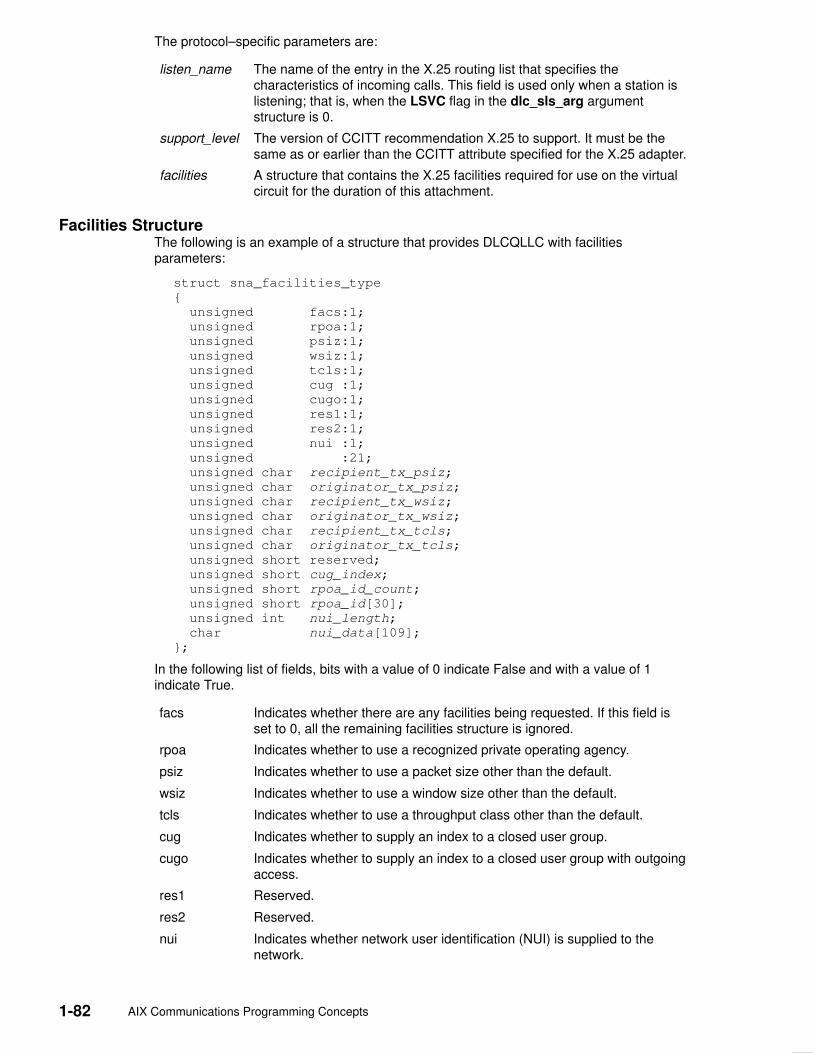
1-82 AIX Communications Programming Concepts
The protocol–specific parameters are:
listen_name The name of the entry in the X.25 routing list that specifies thecharacteristics of incoming calls. This field is used only when a station islistening; that is, when the LSVC flag in the dlc_sls_arg argumentstructure is 0.
support_level The version of CCITT recommendation X.25 to support. It must be thesame as or earlier than the CCITT attribute specified for the X.25 adapter.
facilities A structure that contains the X.25 facilities required for use on the virtualcircuit for the duration of this attachment.
Facilities StructureThe following is an example of a structure that provides DLCQLLC with facilitiesparameters:
struct sna_facilities_type
{
unsigned facs:1;
unsigned rpoa:1;
unsigned psiz:1;
unsigned wsiz:1;
unsigned tcls:1;
unsigned cug :1;
unsigned cugo:1;
unsigned res1:1;
unsigned res2:1;
unsigned nui :1;
unsigned :21;
unsigned char recipient_tx_psiz;
unsigned char originator_tx_psiz;
unsigned char recipient_tx_wsiz;
unsigned char originator_tx_wsiz;
unsigned char recipient_tx_tcls;
unsigned char originator_tx_tcls;
unsigned short reserved;
unsigned short cug_index;
unsigned short rpoa_id_count;
unsigned short rpoa_id[30];
unsigned int nui_length;
char nui_data[109];
};
In the following list of fields, bits with a value of 0 indicate False and with a value of 1indicate True.
facs Indicates whether there are any facilities being requested. If this field isset to 0, all the remaining facilities structure is ignored.
rpoa Indicates whether to use a recognized private operating agency.
psiz Indicates whether to use a packet size other than the default.
wsiz Indicates whether to use a window size other than the default.
tcls Indicates whether to use a throughput class other than the default.
cug Indicates whether to supply an index to a closed user group.
cugo Indicates whether to supply an index to a closed user group with outgoingaccess.
res1 Reserved.
res2 Reserved.
nui Indicates whether network user identification (NUI) is supplied to thenetwork.

Data Link Control 1-83
The remaining fields provide the values or data associated with each of the above facilitiesbits that are set to 1. If the corresponding facilities bit is set to 0, each of these fields isignored:
recipient_tx_psiz Indicates the coded value of packet size to use when sending datato the node that initiated the call. The values are coded as follows:
0x06 = 64 octets
0x07 = 128 octets
0x08 = 256 octets
0x09 = 512 octets
0x0A = 1024 octets
0x0B = 2048 octets
0x0C = 4096 octets
Note: 4096–octet packets are allowed only in the 1984 CCITTrecommendation. For the call to be valid, the value of the X.25CCITT attribute and the corresponding QLLC attribute must beset to 1984.
originator_tx_psiz Indicates the coded value of packet size to use when sending datafrom the node that initiated the call. The values are coded as for therecipient_tx_psiz field.
recipient_tx_wsiz Reserved for QLLC use.
originator_tx_wsiz Reserved for QLLC use.
recipient_tx_tcls Indicates the coded values of the throughput class requested for thisvirtual circuit when sending data to the node that initiated the call.The values are coded as follows:
0x07 = 1200 bits per second
0x08 = 2400 bits per second
0x09 = 4800 bits per second
0x0A = 9600 bits per second
0x0B = 19200 bits per second
0x0C = 48000 bits per second
originator_tx_tcls Indicates the coded values of the throughput class requested for thisvirtual circuit when sending data from the node that initiated the call.The values are coded as for the recipient_tx_tcls field.
cug_index Indicates the decimal value of the index of the closed user group(CUG) within which this call is to be placed. This field is used foreither CUG or CUG with outgoing access (CUGO) facilities.
rpoa_id_count Indicates the number of recognized private operating agency(RPOA) identifiers to supply in the rpoa_id field.
rpoa_id Indicates an array of RPOA identifiers that contains the number ofidentifiers specified in the rpoa_id_count field. The RPOA identifiersappear in the order in which they will be traversed when the call isinitiated. The content of each array element is the decimal value ofan RPOA identifier.

1-84 AIX Communications Programming Concepts
nui_length The length, in bytes, of the nui_data field.
nui_data Network user identification (NUI) data. The contents of this array aredefined by the user in conjunction with the network provider. Notethat the maximum allowable X.25 facilities string is 109 bytes. Evenif NUI is the only facility requested, the facility code occupies onebyte, so it is impossible to send more than 108 bytes of NUI data.Each additional facility requested reduces the space available forNUI data.
DLC_ALTERThe ioctl subroutine argument structure for altering a link station, dlc_alter_arg, has thefollowing specifics:
• The following alter flags are not supported:
AKT Alter acknowledgment time out.
RTE Alter routing.
XWIN Alter transmit window size.
• The acknowledge time out field is ignored.
• The routing data field is ignored.
• The transmit window size field is ignored.
• No protocol–specific data area is required for DLCQLLC to alter its configuration.
DLC_QUERY_SAPThe device driver dependent data returned from DLCQLLC for this ioctl operation is thecio_stats_t structure defined in the /usr/include/sys/comio.h file.
DLC_QUERY_LSThere is no protocol specific data area supported by DLCQLLC for the query link stationioctl operation.
DLC_ENTER_SHOLDThe enter_short_hold option is not supported by DLCQLLC.
DLC_EXIT_SHOLDThe exit_short_hold option is not supported by DLCQLLC.
DLC_ADD_GRPThe add_group or multicast address option is not supported by DLCQLLC.
DLC_ADD_FUNC_ADDRThe add_functional_address option is not supported by DLCQLLC.

Data Link Control 1-85
DLC_DEL_FUNC_ADDRThe delete_functional_address option is not supported by DLCQLLC.
IOCINFOThe ioctype variable is defined as a DD_DLC definition and the subtype is DS_DLCQLLC.
DLCQLLC Asynchronous Function Subroutine CallsNetwork and datagram data are not supported, so the rcvn_fa and rcvd_fa data functionsare never called by DLCQLLC.
DLCQLLC is compatible with each of the other asynchronous function subroutine calls forthe kernel user.

1-86 AIX Communications Programming Concepts
Data Link Control FDDI (DLC FDDI) Overview Fiber distributed data interface (FDDI) data link control (DLC FDDI) is a device managerthat follows the generic interface definition (GDLC). This data link control (DLC) devicemanager provides a passthrough capability that allows transparent data flow as well as anaccess procedure to transfer four types of data over a FDDI network:
• Datagrams
• Sequenced data
• Identification data
• Logical link controls
The access procedure relies on functions provided by the FDDI Device Handler and theFDDI Network Bus Master adapter to transfer data with address checking, token generation,or frame check sequences.
The DLC FDDI device manager provides the following functions and services:
• Device manager functions
• Protocol support
• Name–discovery services
• Direct network services
• Connection contention
• Link sessions
• Programming interfaces

Data Link Control 1-87
DLC FDDI Device Manager Nodes The DLC FDDI device manager operates between two nodes on a fiber distributed datainterface (FDDI) local area network (LAN), using IEEE 802.2 logical link control (LLC)procedures and control information as defined in the Token–Ring Network ArchitectureReference and media access control procedures as defined in the ANSI standardpublication Fiber Distributed Data Interface–Token Ring Media Access Control. The DLCFDDI device manager supports:
• Asynchronous disconnected mode (ADM) and asynchronous balanced mode extended(ABME)
• Two–way simultaneous (full–duplex) data flow
• Multiple point–to–point logical attachments on the LAN using network and service accesspoint (SAP) addresses
• Peer–to–peer relationship with remote station
• Full six–byte addressing
• Both name–discovery and address–resolve services
• Source–routing generation for up to 14 bridge hops
• Asynchronous transmission with eight possible priority levels.
The DLC FDDI provides full–duplex, peer–data transfer capabilities over a FDDI LAN. TheFDDI LAN must use the ANSI X3.139 medium access control (MAC) procedure and asuperset of the IEEE 802.2 LLC protocol as described in the Token–Ring NetworkArchitecture Reference.
Multiple FDDI adapters are supported, with a maximum of 126 SAP users per adapter. Atotal of 255 link stations per adapter are supported, which are distributed among the activeSAP users.
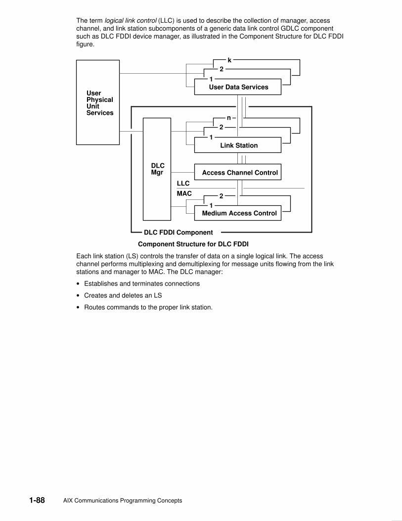
1-88 AIX Communications Programming Concepts
The term logical link control (LLC) is used to describe the collection of manager, accesschannel, and link station subcomponents of a generic data link control GDLC componentsuch as DLC FDDI device manager, as illustrated in the Component Structure for DLC FDDIfigure.
Link Station
Access Channel ControlDLCMgr
UserPhysicalUnitServices
LLC
MAC
1
1
Medium Access Control
2
2
n
1
2
k
DLC FDDI Component
User Data Services
Component Structure for DLC FDDI
Each link station (LS) controls the transfer of data on a single logical link. The accesschannel performs multiplexing and demultiplexing for message units flowing from the linkstations and manager to MAC. The DLC manager:
• Establishes and terminates connections
• Creates and deletes an LS
• Routes commands to the proper link station.
Data Link Control 1-89
DLC FDDI Device Manager Functions The data link control (DLC) fiber distributed data interface (FDDI) device manager andtransport medium use two functional layers, medium access control (MAC) and logical linkcontrol (LLC), to maintain reliable link–level attachments, guarantee data integrity, negotiateexchanges of identification, and support both connection and non–connection orientedservices.
The FDDI adapter and device handler are responsible for the following MAC functions:
• Handling ring–insertion protocol
• Detecting and creating tokens
• Encoding and decoding the serial bit–stream data
• Checking received network and group addresses
• Routing of received frames based on the LLC/MAC/SMT indicator and using thedestination service access point (SAP) address if an LLC frame was received
• Generating frame–check sequences (FCS)
• Handling frame delimiters, such as start or end delimiters and frame–status field
• Handling fail–safe time outs
• Handling network recovery.
The FDDI Device Manager is responsible for additional MAC functions, such as:
• Framing control fields on transmit frames
• Network addressing on transmit frames
• Routing information on transmit frames
• Handling network recovery.
The FDDI Device Manager is also responsible for all LLC functions:
• Handling remote connection services using the address–resolve and name–discoveryprocedures
• Sequencing of link stations on a given port
• Generating SAP addresses on transmit frames
• Generating IEEE 802.2 LLC commands and responses on transmit frames
• Recognizing and routing received frames to the proper service access point
• Servicing of IEEE 802.2 LLC commands and responses on receive frames
• Handling frame sequencing and retries
• Handling fail–safe and inactivity time outs
• Handling reliability counters, availability counters, serviceability counters, error logs, andlink trace.

1-90 AIX Communications Programming Concepts
DLC FDDI Protocol Support The data link control (DLC) fiber distributed data interface (FDDI) device manager supportsthe logical link control (LLC) protocol and state tables described in the Token–Ring NetworkArchitecture Reference, which also contains the local area network (LAN) IEEE 802.2 LLCstandard. Both address–resolve services and name–discovery services are supported forestablishing remote attachments. A direct network interface is also supported to allow usersto transmit and receive unnumbered information packets through DLC FDDI without anyprotocol handling by the data link layer.
Station TypeA combined station is supported for a balanced (peer–to–peer) configuration on a logicalpoint–to–point connection. This allows either station to initiate asynchronously thetransmission of commands at any response opportunity. The sender in each combinedstation controls the receiver in the other station. Data transmissions then flow as primarycommands, and acknowledgments and status flow as secondary responses.
Response ModesBoth asynchronous disconnect mode (ADM) and asynchronous balanced mode extended(ABME) are supported. ADM is entered by default whenever a link session is initiated. Itswitches to ABME only after the set asynchronous balanced mode extended (SABME)packet sequence is complete by way of the DLC_CONTACT command or aremote–initiated SABME packet. Once operating in ABME, information frames containinguser data can be transferred. ABME then remains active until the LLC session ends, whichoccurs because of a disconnect (DISC) packet sequence or a major link error.
FDDI Data PacketAll communication between a local and remote station is accomplished by the transmissionof a packet that contains FDDI headers and trailers, as well as an encapsulated LLC linkprotocol data unit (LPDU). The DLC FDDI Frame Encapsulation figure describes the FDDIdata packet:
<4096 bytes in memory
DSAPAddr.
SSAPAddr.
ControlField
InformationField
2 bytes p bytes1 (2) byte
DestinationAddress
SourceAddress
LPDU
6 bytes
FC
n bytes
FDDI DLC Frame Encapsulation
m bytes
on media
SFS
3 1
FCS EFSRoutingInformation
6 bytes

Data Link Control 1-91
The FDDI data packet consists of the following:
SFS Start–of–frame sequence, including the preamble and starting delimiter
FC Frame control field
LPDU LLC protocol data unit
DSAP Destination service access point (SAP) address field
SSAP Source SAP address field
FCS Frame–check sequence or cyclic redundancy check
EFS End–of–frame sequence, including the ending delimiter and framestatus
m bytes Integer value greater than or equal to 0 and less than or equal to 30
n bytes Integer value greater than or equal to 3 and less than or equal to 4080
p bytes Integer value greater than or equal to 0 and less than or equal to 4077
Note:
1. SFS, FCS, and EFS are added and deleted by the hardware adapter. Three bytes ofalignment always precede the FC field when located in memory buffers.
2. The maximum byte length of a transfer unit has been set to 4096 bytes to align to thesize of an mbuf cluster (where a transfer unit is defined as fields FC through LPDU, plusa three–byte front alignment pad).

1-92 AIX Communications Programming Concepts
DLC FDDI Name–Discovery Services In addition to the standard IEEE 802.2 Common Logical Link Protocol support and addressresolution services, the data link control (DLC) fiber distributed data interface (FDDI) alsoprovides a name–discovery service that allows the operator to identify local and remotestations by name instead of by six–byte physical addresses. Each port must have a uniquename on the network of up to 20 characters. The character set used varies depending onthe user’s protocol. Systems Network Architecture (SNA), for example, requires characterset A. Additionally, each new service access point (SAP) supported on a particular port canhave a unique name if desired.
Each name is added to the network by broadcasting a find (local name) request when thenew name is being introduced to a given network port. If no response other than an echoresults from the find (local name) request after sending it the number of times specified, thephysical link is declared opened. The name is then assigned to the local port and SAP. Ifanother port on the network has already added the name or is in the process of adding aname, a name–found response is sent to the station that issued the find request, and thenew attachment fails with a result code (DLC_NAME_IN_USE). The code indicates adifferent name must be chosen. Calls are established by broadcasting a find (remote name)request to the network and waiting for a response from the port with the specified name.Only those ports that have listen attachments pending, receive colliding find requests, or arealready attached to the requesting remote station answer a find request.
LAN Find Data FormatFind Header
0–1 Byte length of the find packet including the length field
2–3 Key 0x0001
4–n Remaining control vectors
Target Name
0–1 Vector length = 0x000F to 0x0022
2–3 Key 0x0004
4–9 Name structure architecture ID:
4–5 Subvector length = 0x0006
6–7 Key 0x4011
8–9 Identifier = 0x8000 (locally administered)
10–m Object name:
10–11 Subvector length = 0x0005 to 0x000C
12–13 Key 0x4010
14–m Target name (1 to 20 bytes)
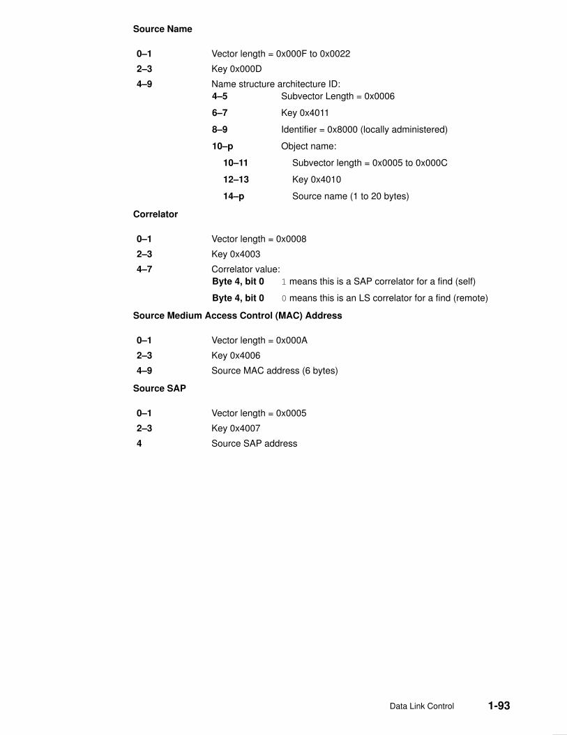
Data Link Control 1-93
Source Name
0–1 Vector length = 0x000F to 0x0022
2–3 Key 0x000D
4–9 Name structure architecture ID:
4–5 Subvector Length = 0x0006
6–7 Key 0x4011
8–9 Identifier = 0x8000 (locally administered)
10–p Object name:
10–11 Subvector length = 0x0005 to 0x000C
12–13 Key 0x4010
14–p Source name (1 to 20 bytes)
Correlator
0–1 Vector length = 0x0008
2–3 Key 0x4003
4–7 Correlator value:
Byte 4, bit 0 1 means this is a SAP correlator for a find (self)
Byte 4, bit 0 0 means this is an LS correlator for a find (remote)
Source Medium Access Control (MAC) Address
0–1 Vector length = 0x000A
2–3 Key 0x4006
4–9 Source MAC address (6 bytes)
Source SAP
0–1 Vector length = 0x0005
2–3 Key 0x4007
4 Source SAP address
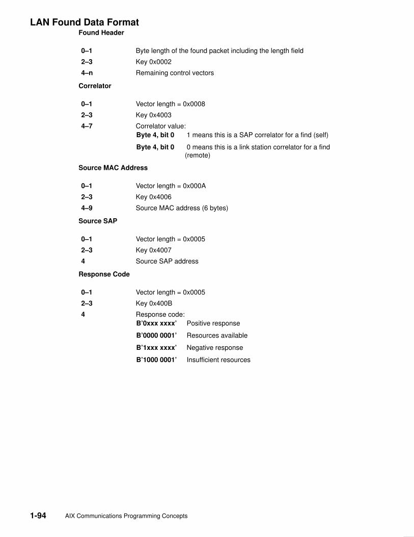
1-94 AIX Communications Programming Concepts
LAN Found Data FormatFound Header
0–1 Byte length of the found packet including the length field
2–3 Key 0x0002
4–n Remaining control vectors
Correlator
0–1 Vector length = 0x0008
2–3 Key 0x4003
4–7 Correlator value:
Byte 4, bit 0 1 means this is a SAP correlator for a find (self)
Byte 4, bit 0 0 means this is a link station correlator for a find(remote)
Source MAC Address
0–1 Vector length = 0x000A
2–3 Key 0x4006
4–9 Source MAC address (6 bytes)
Source SAP
0–1 Vector length = 0x0005
2–3 Key 0x4007
4 Source SAP address
Response Code
0–1 Vector length = 0x0005
2–3 Key 0x400B
4 Response code:
B’0xxx xxxx’ Positive response
B’0000 0001’ Resources available
B’1xxx xxxx’ Negative response
B’1000 0001’ Insufficient resources

Data Link Control 1-95
DLC FDDI Direct Network Services Some users wish to handle their own unnumbered information packets on the networkwithout the aid of the data link layer within the fiber distributed data interface (FDDI). Adirect network interface allows an entire packet to be generated and sent by users oncetheir service access point (SAP) has been opened. This allows full control of every field inthe data link header for each write issued. Also provided is the ability to view the entirepacket contents on received frames. The criteria for a direct network write are:
• The local SAP must be valid and opened
• The data link control byte must indicate unnumbered information (0x03).

1-96 AIX Communications Programming Concepts
DLC FDDI Connection Contention Dual paths to the same nodes are detected by the data link control (DLC) fiber distributeddata interface (FDDI) in one of two ways. If a call is in progress to a remote node, which isalso trying to call a local node, the incoming find (remote name) request is treated as if alocal listen was outstanding. If a pending local listen has been acquired by a remote node’scall, and the local user issues a call to that remote node after the link station is alreadyactive, a result code (DLC_REMOTE_CONN) is returned to the user along with the linkstation correlator of the attachment already active, so that the user can relink attachmentpointers.
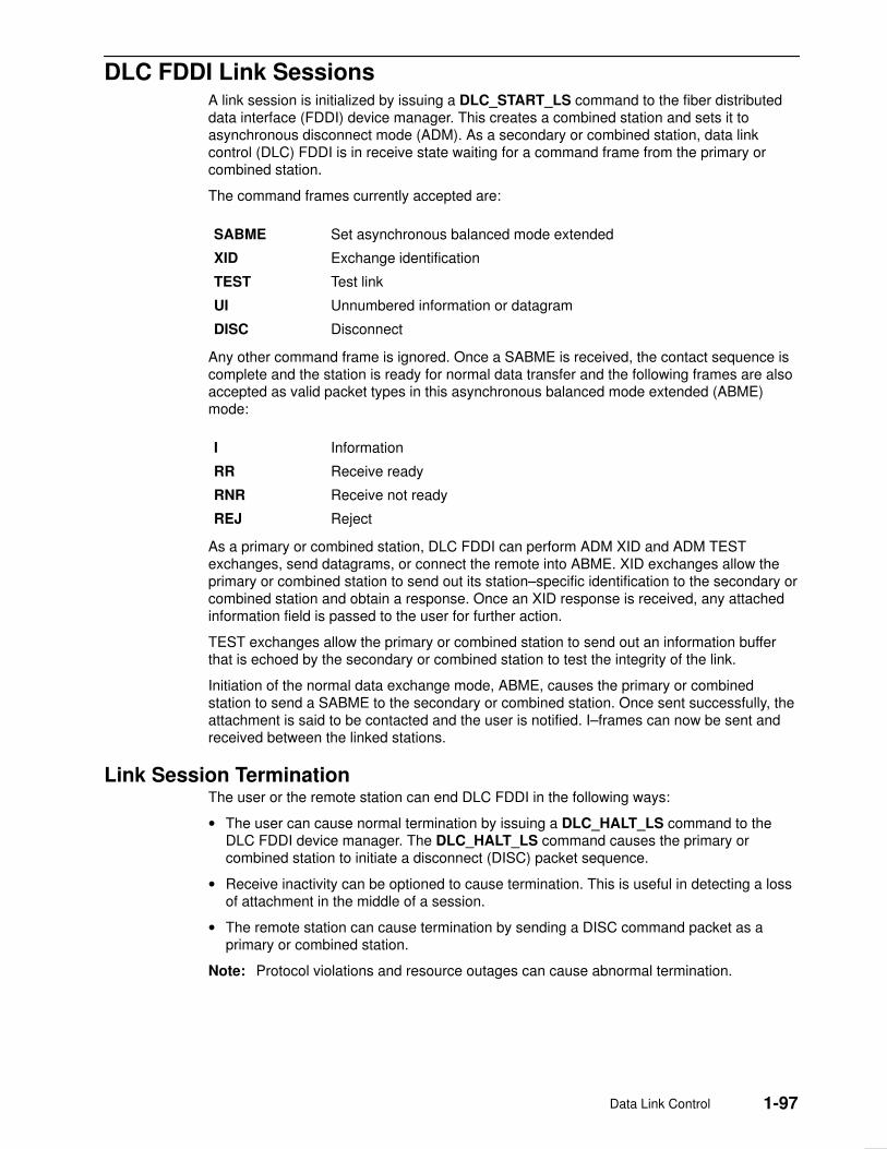
Data Link Control 1-97
DLC FDDI Link Sessions A link session is initialized by issuing a DLC_START_LS command to the fiber distributeddata interface (FDDI) device manager. This creates a combined station and sets it toasynchronous disconnect mode (ADM). As a secondary or combined station, data linkcontrol (DLC) FDDI is in receive state waiting for a command frame from the primary orcombined station.
The command frames currently accepted are:
SABME Set asynchronous balanced mode extended
XID Exchange identification
TEST Test link
UI Unnumbered information or datagram
DISC Disconnect
Any other command frame is ignored. Once a SABME is received, the contact sequence iscomplete and the station is ready for normal data transfer and the following frames are alsoaccepted as valid packet types in this asynchronous balanced mode extended (ABME)mode:
I Information
RR Receive ready
RNR Receive not ready
REJ Reject
As a primary or combined station, DLC FDDI can perform ADM XID and ADM TESTexchanges, send datagrams, or connect the remote into ABME. XID exchanges allow theprimary or combined station to send out its station–specific identification to the secondary orcombined station and obtain a response. Once an XID response is received, any attachedinformation field is passed to the user for further action.
TEST exchanges allow the primary or combined station to send out an information bufferthat is echoed by the secondary or combined station to test the integrity of the link.
Initiation of the normal data exchange mode, ABME, causes the primary or combinedstation to send a SABME to the secondary or combined station. Once sent successfully, theattachment is said to be contacted and the user is notified. I–frames can now be sent andreceived between the linked stations.
Link Session TerminationThe user or the remote station can end DLC FDDI in the following ways:
• The user can cause normal termination by issuing a DLC_HALT_LS command to theDLC FDDI device manager. The DLC_HALT_LS command causes the primary orcombined station to initiate a disconnect (DISC) packet sequence.
• Receive inactivity can be optioned to cause termination. This is useful in detecting a lossof attachment in the middle of a session.
• The remote station can cause termination by sending a DISC command packet as aprimary or combined station.
Note: Protocol violations and resource outages can cause abnormal termination.
1-98 AIX Communications Programming Concepts
DLC FDDI Programming Interfaces The data link control (DLC) fiber distributed data interface (FDDI) conforms to generic datalink control (GDLC) guidelines except where noted below. Additional structures anddefinitions for DLC FDDI are found in the /usr/include/sys/fdlextcb.h file.
The following entry points are supported by DLC FDDI:
Note: The dlc prefix is replaced with the fdl prefix for the DLC FDDI device manager.
fdlclose Fully compatible with the dlcclose GDLC interface.
fdlconfig Fully compatible with the dlcconfig GDLC interface. No initializationparameters are required.
fdlmpx Fully compatible with the dlcmpx GDLC interface.
fdlopen Fully compatible with the dlcopen GDLC interface.
fdlread Compatible with the dlcread GDLC interface with the followingconditions:
• The readx subroutines may have DLC FDDI data link headerinformation prefixed to the information field (I–field) being passed tothe application. This is optional based on the readx subroutine datalink header length extension parameter in the gdl_io_ext structure.
• If this field is nonzero, DLC FDDI copies the data link header and theI–field to user space, and sets the actual length of the data linkheader into the length field.
• If the field is 0, no data link header information is copied to userspace. See the DLC FDDI frame encapsulation, on page 1-90 formore details.
Kernel receive packet function handlers always have the DLC FDDIdata link header information within the communications memory buffer(mbuf), and can locate it by subtracting the length passed (in thegdl_io_ext structure) from the data offset field of the mbuf structure.
fdlselect Fully compatible with the dlcselect GDLC interface.
fdlwrite Compatible with the dlcwrite GDLC interface, with the exception thatnetwork data can only be written as an unnumbered information (UI)packet and must have the complete data link header prefixed to thedata. DLC FDDI verifies that the local (source) SAP is enabled and thatthe control byte is UI (0x03). See the DLC FDDI frame encapsulation,on page 1-90 for more details.

Data Link Control 1-99
fdlioctl Compatible with the dlcioctl GDLC interface. The following ioctloperations contain FDDI–specific conditions on GDLC operations:
• DLC_ENABLE_SAP
• DLC_START_LS
• DLC_ALTER
• DLC_ENTER_SHOLD
• DLC_EXIT_SHOLD
• DLC_ADD_GRP
• DLC_ADD_FUNC_ADDR
• DLC_DEL_FUNC_ADDR
• DLC_DEL_GRP
• DLC_QUERY_SAP
• DLC_QUERY_LS
• IOCINFO
The following sections describe these conditions.
DLC_ENABLE_SAPThe ioctl subroutine argument structure for enabling a SAP, dlc_esap_arg, has thefollowing specifics:
• The grp_addr (group address) field contains the full six–byte group address with theindividual control bits, group control bits, universal control bits, and local control bitslocated in the most significant bit positions of the first (leftmost) byte.
• The func_addr_mask (functional address mask) field is not supported.
• The max_ls (maximum link stations) field cannot exceed a value of 255.
• The following common SAP flags are not supported:
NTWK Indicates a teleprocessing network type.
LINK Indicates a teleprocessing link type.
PHYC Represents a physical network call (teleprocessing).
ANSW Indicates a teleprocessing autocall and autoanswer.
• Group SAPs are not supported, so the num_grp_saps (number of group SAPs) field mustbe set to 0.
• The laddr_name (local address or name) field and its associated length are only used forname discovery when the common SAP flag ADDR is set to 0. When resolve proceduresare used (the ADDR flag set to 1), DLC FDDI obtains the local network address from thedevice handler and not from the dlc_esap_arg structure.
• The local_sap (local service access point) field can be set to any value except the nullSAP (0x00) or the name–discovery SAP (0xFC). Also, the low–order bit must be set to 0(B‘nnnnnnn0’) to indicate an individual address.
• No protocol–specific data area is required for DLC FDDI to enable an SAP.

1-100 AIX Communications Programming Concepts
DLC_START_LSThe ioctl subroutine argument structure for starting a link station, dlc_sls_arg, has thefollowing specifics:
• The following common link station flags are not supported:
STAT Indicates a station type for SDLC.
NEGO Indicates a negotiable station type for SDLC.
• The raddr_name (remote address or name) field is used only for outgoing calls when theDLC_SLS_LSVC common link station flag is active.
• The maxif (maximum I–field length) field can be set to any value greater than 0. The DLCFDDI device manager adjusts this value to a maximum of 4077 bytes if set too large. Seethe DLC FDDI frame encapsulation figure, on page 1-90 for more details.
• The rcv_wind (receive window) field can be set to any value from 1 to 127, inclusive. Therecommended value is 127.
• The xmit_wind (transmit window) field can be set to any value from 1 to 127, inclusive.The recommended value is 26.
• The rsap (remote SAP) field can be set to any value except the null SAP (0x00) or thename–discovery SAP (0xFC). Also, the low–order bit must be set to 0 (B‘nnnnnnn0’) toindicate an individual address.
• The max_repoll field can be set to any value from 1 to 255, inclusive. The recommendedvalue is 8.
• The repoll_time field is defined in increments of 0.5 seconds and can be set to any valuefrom 1 to 255, inclusive. The recommended value is 2, giving a time–out duration of 1 to1.5 seconds.
• The ack_time (acknowledgment time) field is defined in increments of 0.5 seconds, andcan be set to any value from 1 to 255, inclusive. The recommended value is 1, giving atime–out duration of 0.5 to 1 second.
• The inact_time (inactivity time) field is defined in increments of 1 second and can be setto any value from 1 to 255, inclusive. The recommended value is 48, giving a time–outduration of 48 to 48.5 seconds.
• The force_time (force halt time) field is defined in increments of 1 second and can be setto any value from 1 to 16383, inclusive. The recommended value is 120, giving atime–out duration of approximately 2 minutes.
• A protocol–specific data area must be appended to the generic start link station (LS)argument (dlc_sls_arg). This structure provides DLC FDDI with additionalprotocol–specific configuration parameters:
struct fdl_start_psd
{
uchar_t pkt_prty; /* ring access packet priority */
uchar_t dyna_wnd; /* dynamic window increment */
ushort_t reserved; /* currently not used */
};

Data Link Control 1-101
The protocol–specific parameters are:
pkt_prty Specifies the ring–access priority that the user wishes to reserve ontransmit packets. Values of 0 to 7 are supported, where 0 is thelowest priority and 7 is the highest priority.
dyna_wnd Network congestion causes the local transmit window count toautomatically drop to a value of 1. The dynamic window incrementspecifies the number of consecutive sequenced packets that must beacknowledged by the remote station before the local transmit windowcount can be increment. This allows a gradual increase in networktraffic after a period of congestion. This field can be set to any valuefrom 1 to 255; the recommended value is 1.
DLC_ALTERThe ioctl subroutine argument structure for altering a link station, dlc_alter_arg, has thefollowing specifics:
• The following common alter flags are not supported:
SM1, SM2 Sets SDLC control mode.
RTE Alters routing.
• A protocol–specific data area must be appended to the generic alter link station argumentstructure (dlc_alter_arg). This structure provides DLC FDDI with additionalprotocol–specific alter parameters.
#define FDL_ALTER_PRTY 0x80000000 /* alter packet priority */
#define FDL_ALTER_DYNA 0x40000000 /* alter dynamic window incr*/
struct fdl_alter_psd
{
ulong_t flags; /* specific alter flags */
uchar_t pkt_prty; /* ring access packet priority value */
uchar_t dyna_wnd; /* dynamic window increment value */
ushort_t reserved; /* currently not used */
};
• Specific alter flags include:
FDL_ALTER_PRTY Specifies alter priority. If set to 1, the pkt_prty value fieldreplaces the current priority value being used by the linkstation. The link station must be started for this alter commandto be valid.
FDL_ALTER_DYNA Specifies alter dynamic window. If set to 1, the dyna_wndvalue field replaces the current dynamic window value beingused by the link station. The link station must be started forthis alter command to be valid.
The protocol–specific parameters are:
pkt_prty Specifies the new priority reservation value for transmit packets.
dyna_wnd Specifies the new dynamic window value to control network congestion.

1-102 AIX Communications Programming Concepts
DLC_ENTER_SHOLDThe enter_short_hold option is not supported.
DLC_EXIT_SHOLDThe exit_short_hold option is not supported.
DLC_ADD_GROUPThe add_group, or multicast address, option is supported by DLC FDDI as a six–byte valueas described above in DLC_ENABLE_SAP (group address).
The grp_addr (group address) field for FDDI contains the full six–byte group address withthe individual/group and universal/local control bits located in the most significant bitpositions of the first (leftmost) byte.
DLC_ADD_FUNC_ADDRThe add_functional_address option is not supported.
DLC_DEL_FUNC_ADDRThe delete_functional_address option is not supported.
DLC_DEL_GRPThe delete group or multicast option is supported by the DLC FDDI device manager. Theaddress being removed must match an address that was added with a DLC_ENABLE_SAPor DLC_ADD_GRP ioctl operation.
DLC_QUERY_SAPThe device driver–dependent data returned from DLC FDDI for this ioctl operation is thefddi_ndd_stats_t structure defined in the /usr/include/sys/cdli_fddiuser.h file.
DLC_QUERY_LSThere is no protocol–specific data area supported by DLC FDDI for this ioctl operation.
IOCINFOThe ioctype variable returned is defined as a DD_DLC definition and the subtype returnedis DS_DLCFDDI.
Asynchronous Function CallsDLC FDDI is fully compatible with the GDLC interface concerning asynchronous functioncalls to the kernel mode user.

Data Link Provider Interface Implementation 2-1
Chapter 2. Data Link Provider Interface Implementation
The AIX Data Link Provider Interface (DLPI) implementation is designed to follow AT&T’s”UNIX International OSI Work Group Data Link Provider Interface” Version 2 (DRAFT)specification. You can obtain a copy electronically if you have Internet access. Refer to”Obtaining Copies of the DLPI Specifications”, on page 2-9 for information about obtainingthe DLPI specification.
It is assumed that you are familiar with the DLPI Version 2 specification published by UNIXInternational, RFC1042, and the various IEEE 802.x documents.
Note: In the text below, the term dlpi refers to the driver, while DLPI refers to thespecification.
The dlpi driver is implemented as a style 2 provider and supports both the connectionlessand connection–oriented modes of communication. For a list of the primitives supported bythe dlpi driver, see ”DLPI Primitives”, on page 2-8.
Primitive Implementation SpecificsInformation pertinent to specific primitives implemented in the dlpi driver is documented inthe man page for that primitive.
Packet Format Registration SpecificsThe dlpi driver supports generic Common Data Link Interface (CDLI) network interfaces byallowing the user to specify the particular packet format necessary for the transmissionmedia over which the stream is created. Using the M_IOCTL or M_CTL streams message,the user can specify the packet format. If no packet format is specified, the default isNS_PROTO.
The DLPI user specifies the packet format through the STREAMS I_STR ioctl. For example,to change the address format to one compatible with Version 3.2.5:
int
fixaddr(int fd) {
int old=NS_PROTO_DL_COMPAT;
return istr(fd, DL_PKT_FORMAT, (char *)&old, sizeof(int));
}
To select a raw stream, enter:
int
beraw(int fd) {
int raw=NS_INCLUDE_MAC;
return istr(fd, DL_PKT_FORMAT, (char *)&raw, sizeof(int));
}
The DLPI user is allowed one packet format specification per stream. This packet formatmust be specified after the attach and before the bind. Otherwise, an error is generated.
The packet formats defined in /usr/include/sys/cdli.h follow:
NS_PROTO Remove all link–level headers. Sub–Network AccessProtocol (SNAP) is not used.
NS_PROTO_SNAP Remove all link–level headers including SNAP.
NS_INCLUDE_LLC Leave LLC headers in place.
NS_INCLUDE_MAC Do not remove any headers.

2-2 AIX Communications Programming Concepts
The packet formats defined in the /usr/include/sys/dlpi_aix.h file are:
NS_PROTO_DL_COMPAT Use the Version 3.2.5 DLPI address format.
NS_PROTO_DL_DONTCARE
No addresses present in DL_UNITDATA_IND. For theDL_UNITDATA_IND primitive, DLPI provides the headerinformation in the dl_unitdata_ind_t structure.
All packet formats except NS_INCLUDE_MAC accept downstream addresses in thefollowing form:
mac_addr.dsap[.snap].
Individually, packet formats have the following requirements:
NS_PROTO orNS_PROTO_SNAP
Medium access control (MAC) and logical link control (LLC)are included in the DLPI header, and the data portion of themessage contains only data. The NS_PROTO header doesnot include SNAP; the NS_PROTO_SNAP header does.Both packet formats present destination addresses asmac_addr and source addresses asmac_addr.ssap.dsap.ctrl[.snap].
For the DL_UNITDATA_REQ primitive, the DLPI user mustprovide the destination address and an optional destinationservice access point (DSAP) in the DLPI header. If the DLPIuser does not specify the DSAP, the DSAP specified at bindtime is used.
NS_PROTO_DONTCARE The dlpi driver places no addresses in the upstreamDL_UNITDATA_IND. Addresses are still required on theDL_UNITDATA_REQ.
NS_PROTO_DL_COMPAT The dlpi driver uses the address format used in the Version3.2.5 dlpi driver, which is identical both upstream anddownstream. The source and destination addresses arepresented as mac_addr.dsap[.snap].
NS_INCLUDE_LLC The DLPI header contains only the destination and sourceaddresses. Only the LLC is placed in the M_DATA portionof the DL_UNITDATA_IND message. Both the source anddestination addresses are presented as mac_addr .
For the DL_UNITDATA_REQ primitive, the DLPI user mustprovide the destination address and an optional DSAP inthe DLPI header. If the DLPI user does not specify theDSAP, the DSAP specified at bind time is used.
NS_INCLUDE_MAC The MAC and LLC are both placed in the data portion of themessage. Thus, the DLPI user must have knowledge of theMAC header and LLC architecture for a specific interface toretrieve the MAC header and LLC from the data portion ofthe message. This format sets the stream to raw mode,which does not process incoming or outgoing messages.
For the DL_UNITDATA_REQ primitive, the DLPI user mustprovide the destination address and an optional DSAP inthe DLPI header. If the DLPI user does not specify theDSAP, the DSAP specified at bind time is used.
Downstream messages do not require theDL_UNITDATA_REQ header and must be received asM_DATA messages. Downstream messages must containa completed MAC header, which will be copied to themedium without further translation.

Data Link Provider Interface Implementation 2-3
Address Resolution Routine Registration SpecificsThe dlpi driver can support all generic interface types. DLPI is implemented to allow theuser to specify address resolution routines for input and output using the STREAMS I_STRioctl or to rely on the system default routines. AIX provides default address resolutionroutines (stored in the /usr/include/sys/ndd.h file) that are interface specific.
The default input address resolution routine is:
ndd–>ndd_demuxer–>nd_address_input
The dlpi driver calls the input address resolution routine with a pointer to the MAC header(and, optionally, the LLC header) and a pointer to a memory buffer (mbuf) structurecontaining data. The actual contents of the data area depend on which type of packetformat was specified. (See ”Packet Format Registration Specifics”, on page 2-1.)
The default output address resolution routine is:
ndd–>ndd_demuxer–>nd_address_resolve
The dlpi driver calls the output address resolution routine with a pointer to an output_bundlestructure (described in /usr/include/net/nd_lan.h), an mbuf structure, and an ndd structure.The driver assigns the destination address to key_to_find and copies the pkt_format and bind time llc into helpers. If the user has provided a different DSAP than what wasset at bind time, the driver also copies the DSAP values into helpers.The output resolutionroutine completes the MAC header and calls the ndd_output subroutine.
If you choose to specify an input and/or output address resolution routine, use the followingsample code:
noinres(int fd) {
return istr(fd, DL_INPUT_RESOLVE, 0);
}
ioctl SpecificsThe dlpi driver supports the following ioctl operations:
• DL_ROUTE
• DL_TUNE_LLC
• DL_ZERO_STATS
• DL_SET_REMADDR
These commands and their associated data structures are described in the/usr/include/sys/dlpi_aix.h header file.
Note: The ioctl commands that require an argument longer than one long word, or thatspecify a pointer for either reading or writing, must use the I_STR format, as in thefollowing example:
int
istr(int fd, int cmd, char *data, int len) {
struct strioctl ic;
ic.cmd = cmd;
ic.timout = –1;
ic.dp = data;
ic.dp = data;
ic.len = len;
return ioctl(fd, I_STR, &ic);
}

2-4 AIX Communications Programming Concepts
DL_ROUTE Disables the source routing on the current stream, queries theDynamic Route Discovery (DRD) for a source route, or staticallyassigns a source route to this stream. It is only accepted when thestream is idle (DL_IDLE).
• If the argument length is 0, no source route is used on outgoingframes.
• If the argument length is equal to the length of the MACaddress for the current medium (for example, 6 for most 802.xproviders), the DRD algorithm is used to obtain the sourceroute for the address specified in the argument. The MACaddress is replaced with the source route on return from theioctl.
• Otherwise, the argument is assumed to contain an address ofthe form mac_addr.source_route, and the source_routeportion is used as the source route for this stream in allcommunications.
As an example, the following code can be used to discover thesource route for an arbitrary address:
char *
getroute(int fd, char *addr, int len) {
static char route[MAXROUTE_LEN];
bcopy(addr, route, len);
if (istr(fd, DL_ROUTE, route, len))
return 0;
return route;
}
Data Link Provider Interface Implementation 2-5
DL_TUNE_LLC Allows the DLS user to alter the default LLC tunable parameters.The argument must point to an llctune_t data structure.
The flags field is examined to determine which, if any, parametersshould be changed. Each bit in the flags field corresponds to asimilarly named field in the llctune_t; if the bit is set, thecorresponding parameter is set to the value in llctune_t. Only thecurrent stream is affected, and changes are discarded when thestream is closed.
If the F_LLC_SET flag is set and the user has root authority, thealtered parameters are saved as the new default parameters forall new streams.
This command returns as its argument an update of the currenttunable parameters.
For example, to double the t1 value, the following code mightbe used:
int
more_t1(int fd) {
llctune_t t;
t.flags = 0;
if (istr(fd, DL_TUNE_LLC, &t,
sizeof(t)))
return –1;
t.flags = F_LLC_T1;
t.t1 *= 2;
return istr(fd, DL_TUNE_LLC, &t,
sizeof(t));
}
To query the tunables, issue DL_TUNE_LLC with the flags fieldset to zero. This will alter no parameters and return the currenttunable values.

2-6 AIX Communications Programming Concepts
DL_ZERO_STATS Resets the statistics counters to zero. The driver maintains twoindependent sets of statistics, one for each stream (local), andanother that is the cumulative statistics for all streams (global).
This command accepts a simple boolean argument. If theargument is True (nonzero), the global statistics are zeroed.Otherwise, only the current stream’s statistics are zeroed.
For example, to zero the statistics counters on the current stream,the following code might be used:
int
zero_stats(int fd) {
return ioctl(fd, DL_ZERO_STATS, 0);
}
DL_SET_REMADDR Allows XID/TEST exchange on connection–oriented streamswhile still in the DL_IDLE state.
The dlpi driver uses both the source (remote) address and thedl_sap to determine where to route incoming messages forconnection–oriented streams. The remote address is ordinarilyspecified in DL_CONNECT_REQ. If the DLS user needs toexchange XID or TEST messages before connecting to theremote station, DL_SET_REMADDR must be used.
Note: Note that this command is not necessary if XID andTEST messages are to be exchanged only when the state isDL_DATAXFER.
The argument to this command is the remote MAC address. Onepossible code fragment might be:
int
setaddr(int fd, char *addr, int len) {
return istr(fd, DL_SET_REMADDR, addr,
len);
}
Dynamic Route DiscoveryDynamic Route Discovery (DRD) is an algorithm used to automatically discover the propersource route that reaches a remote station on either a token ring or a Fiber Distributed DataInterface (FDDI) network. It relieves the DLS user from discovering and maintaining sourceroutes. The algorithm implements the spanning tree, as recommended by 802.5.
When the DLS user issues a transmission request (for example, DL_CONNECT_REQ orDL_UNITDATA_REQ) on a medium supporting source routing, the DRD algorithm consultsa local cache of source routes. If there is a hit, the cached source route is used immediately.Otherwise, the DRD queues the transmission request and starts the discovery algorithm. Ifthe algorithm finds a source route, the new route is cached, and the queued requests aretransmitted using this new route. If the algorithm times out with no replies (approximately 10seconds), the queued requests are rejected.
The cache is periodically flushed of stale entries. An entry becomes stale after 5 minutes ofno new requests.
Note: After a connection is established, the source route discovered during the connectionsetup is used to the exclusion of the DRD. This has two effects:
• If the source route changes during a connection, the connection continues to use theoriginal source route.
• If the original source route becomes invalid, the connection breaks, and no rediscovery isattempted until a new connection is started.

Data Link Provider Interface Implementation 2-7
DRD ConfigurationThe DRD is selectable on a per–media basis when the dlpi driver is first loaded into thekernel. By default, the DRD is disabled for all media types. It can be enabled by appendingthe string ” ,r” (uses routing) to the argument field in /etc/dlpi.conf. Once selected, it isused by all physical points of attachment (PPAs) for that media type. The following exampleconfigurations both show token ring and FDDI configured, first in a default configuration andthen with DRD enabled.
Default configuration:
d+ dlpi tr /dev/dlpi/tr
d+ dlpi fi /dev/dlpi/fi
DRD–enabled configuration:
d+ dlpi tr,r /dev/dlpi/tr
d+ dlpi fi,r /dev/dlpi/fi
Connectionless Mode Only DLPI Driver versusConnectionless/Connection–Oriented DLPI DriverAttention:
1. For binary compatibility purposes, there are no new statistics added for theconnection–oriented functions. Statistics for the connection–oriented functions will beprovided in a future release of AIX.
2. For binary compatibility purposes, a DL_UNITDATA_IND header is provided in themessages for promiscuous mode and raw mode. Be aware that this header will beremoved in a future release of AIX.
The following sample code fragment works with the 4.1 and later versions of DLPI:
if (raw_mode) {
if (mp–>b_datap–>db_type == M_PROTO) {
union DL_primitives *p;
p = (union DL_primitives *)mp–>b_rptr;
if (p–>dl_primitive == DL_UNITDATA_IND) {
mblk_t *mpl = mp–>b_cont;
freeb(mp);
mp = mpl;
}
}
}
The above code fragment discards the DL_UNITDATA_IND header. For compatibilitywith future releases, it is recommended that you parse the frame yourself. The MAC andLLC headers are presented in the M_DATA message for both promiscuous mode andraw mode.
Raw mode currently accepts, but does not require, a DL_UNITDATA_REQ. In a futurerelease of AIX, raw mode will not accept a DL_UNITDATA_REQ; only M_DATA will beaccepted.
The dlpi driver supports the 802.2 connection–oriented service over the CDLI–based media802.3, token ring, and FDDI. Other CDLI–based media can be supported provided themedia implementation follows the IEEE 802.x recommendations.
The DL_BIND_REQ primitive accepts values for some fields (refer to the DL_BIND_REQprimitive in AIX Technical Reference, Volume 3: Communications).
The DL_OUTPUT_RESOLVE and DL_INPUT_RESOLVE ioctl commands replace thedefault address resolution routines for the current stream. They are no longer accepted fromuser space; the message type must be M_CTL (not M_IOCTL), and they are only acceptedbefore the stream is bound. DL_INPUT_RESOLVE is accepted as an M_IOCTL messageonly if its argument is zero; this allows the user to disable input address resolution. Outputaddress resolution cannot be disabled––use the raw mode if transparent access to themedium is required.

2-8 AIX Communications Programming Concepts
The DL_PKT_FORMAT ioctl command now recognizes and handles the following packetformats: NS_PROTO, NS_PROTO_SNAP, NS_PROTO_DL_DONTCARE,NS_PROTO_DL_COMPAT, NS_INCLUDE_LLC, and NS_INCLUDE_MAC.
New ioctl commands are now supported: DL_ROUTE, DL_TUNE_LLC, DL_ZERO_STATS,and DL_SET_REMADDR. Refer to ”ioctl Specifics, on page 2-3.
DLPI PrimitivesThe following primitives are supported by DLPI:
• DL_ATTACH_REQ
• DL_BIND_ACK
• DL_BIND_REQ
• DL_DETACH_REQ
• DL_DISABMULTI_REQ
• DL_ENABMULTI_REQ
• DL_ERROR_ACK
• DL_GET_STATISTICS_REQ
• DL_GET_STATISTICS_ACK
• DL_INFO_ACK
• DL_INFO_REQ
• DL_OK_ACK
• DL_PHYS_ADDR_REQ
• DL_PHYS_ADDR_ACK
• DL_PROMISCOFF_REQ
• DL_PROMISCON_REQ
• DL_SUBS_BIND_ACK
• DL_SUBS_BIND_REQ
• DL_SUBS_UNBIND_REQ
• DL_TEST_CON
• DL_TEST_IND
• DL_TEST_REQ
• DL_TEST_RES
• DL_UDERROR_IND
• DL_UNBIND_REQ
• DL_UNITDATA_IND
• DL_UNITDATA_REQ
• DL_XID_CON
• DL_XID_IND
• DL_XID_REQ
• DL_XID_RES
Data Link Provider Interface Implementation 2-9
The following connection–oriented service primitives are supported:
• DL_CONNECT_REQ
• DL_CONNECT_IND
• DL_CONNECT_RES
• DL_CONNECT_CON
• DL_TOKEN_REQ
• DL_TOKEN_ACK
• DL_DATA_REQ
• DL_DATA_IND
• DL_DISCONNECT_REQ
• DL_DISCONNECT_IND
• DL_RESET_REQ
• DL_RESET_IND
• DL_RESET_RES
• DL_RESET_CON
The following primitives are not supported:
• DL_UDQOS_REQ
• DL_SET_PHYS_ADDR_REQ
The following acknowledged connectionless–mode primitives are not supported:
• DL_DATA_ACK_REQ
• DL_DATA_ACK_IND
• DL_DATA_ACK_STATUS_IND
• DL_REPLY_REQ
• DL_REPLY_IND
• DL_REPLY_STATUS_IND
• DL_REPLY_UPDATE_REQ
• DL_REPLY_UPDATE_STATUS_IND
Note: If any unsupported primitive is issued to the provider, the provider will return theDL_ERROR_ACK primitive with the DL_NOTSUPPORTED error code.
Obtaining Copies of the DLPI SpecificationsYou can obtain copies of the Data Link Provider Interface (DLPI) specifications electronicallyusing File Transfer Protocol (FTP) commands. A postscript version of the DLPIspecifications may be retrieved electronically by anonymous ftp from any of the following listof Internet hosts.
liasun3.epfl.chmarsh.cs.curtin.edu.auftp.eu.netopcom.sun.caftp.cac.psu.edu
IP address128.178.155.12134.7.1.1192.16.202.2142.77.1.61128.118.2.23
Pathname/pub/sun/dlpi/pub/netman/dlpi/network/netman/dlpi/pub/drivers/dlpi/pub/unix/netman/dlpi
Host
2-10 AIX Communications Programming Concepts
To retrieve the postscript DLPI specifications through anonymous ftp, use the followingexample:
ftp ftp.eu.net
Connected to eunet.EU.net.
220–
220–Welcome to the central EUnet Archive,
220–
220 eunet.EU.net FTP server (Version wu–2.4(2) Jul 09 1993)
ready.
Name (ftp.eu.net:jhaug):anonymous
ftp> user anonymous
331 Guest login ok, send your complete e–mail address as
password.
Password:
ftp> cd /network/netman/dlpi
250 CWD command successful.
ftp> bin
200 Type set to I.
ftp> get dlpi.ps.Z
200 PORT command successful.
150 Opening BINARY mode data connection for dlpi.ps.Z (479345
bytes).
226 Transfer complete.
1476915 bytes received in 39.12 seconds (11.97 Kbyte/s)
ftp> quit
221 Goodbye.
There is no guarantee that a public Internet server will always be available. If the abovepublic Internet server host is not available, you might try using one of the Internet archiveserver listing services, such as Archie, to search for a public server that has the DLPIspecifications.

New Database Manager 3-1
Chapter 3. New Database Manager
The New Database Manager (NDBM) subroutines maintain key and content pairs in adatabase. The NDBM subroutines handle large databases and access keyed items in oneor two file system accesses. Keyed items are consecutive characters, taken from a datarecord, that identify the record and establish its order with respect to other records.
NDBM databases are stored in two files. One file is a directory containing a bit map and ithas the extension .dir. The second file contains only data and has the extension .pag.
For example, Network Information Service (NIS) maps maintain database information inNDBM format. NIS maps are created using the makedbm command. The makedbmcommand converts input into NDBM format files. An NIS map consists of two files:map.key.pag and map.key.dir. The file with the .dir extension serves as an index for the.pag files. The file with the .pag extension contains the key and value pairs.
Note: The NDBM library replaces the earlier Database Manager (DBM) library, whichmanaged a single database.
Using NDBM SubroutinesTo access a database, issue the dbm_open subroutine. The dbm_open subroutine opensor creates the file.dir and file.pag files, depending on the flags parameter. To close adatabase, issue the dbm_close subroutine. Close one database before opening anotherdatabase.
Other NDBM subroutines include:
dbm_delete Deletes a key and its associated contents.
dbm_fetch Accesses data stored under a key.
dbm_firstkey Returns the first key in the database.
dbm_nextkey Returns the next key in the database.
dbm_store Stores data under a key.
Diagnosing NDBM ProblemsA return value of 0 indicates no error. Subroutines that return a negative value indicate anerror has occurred. A positive integer return indicates the status of the return. For example,if the dbm_store subroutine, issued with an insert flag, finds an existing entry with the samekey, it returns a 1.
The dbm_fetch, dbm_firstkey, and dbm_nextkey subroutines return a datum structurecontaining the value returned for the specified key. If the subroutine is unsuccessful, a nullvalue is indicated in the dptr field of the datum structure.

3-2 AIX Communications Programming Concepts
List of NDBM and DBM Programming References This list includes both New Database Manager (NDBM) subroutines and their equivalentDatabase Manager (DBM) subroutines.
NDBM Subroutines
dbm_close Closes a database.
dbm_delete Deletes a key and its associated contents.
dbm_fetch Accesses data stored under a key.
dbm_firstkey Returns the first key in the database.
dbm_nextkey Returns the next key in the database.
dbm_open Opens a database for access.
dbm_store Stores data under a key.
DBM Subroutines
dbmclose Closes a database.
dbminit Opens a database.
delete Deletes a key and its associated contents.
fetch Accesses the data stored under a key.
firstkey Returns the first key that matches the specification.
nextkey Returns the next key in the database.
store Stores data under a key.

eXternal Data Representation 4-1
Chapter 4. eXternal Data Representation
The eXternal Data Representation (XDR) is a standard for the description and encoding ofdata. XDR uses a language to describe data formats, but the language is used only fordescribing data and is not a programming language. Protocols such as Remote ProcedureCall (RPC) and the Network File System (NFS) use XDR to describe their data formats.
This chapter discusses the following topics:
• eXternal Data Representation Overview for Programming
• XDR Subroutine Format
• XDR Library
• XDR Language Specification
• XDR Data Types
• List of XDR Programming References
• XDR Library Filter Primitives
• XDR Non–Filter Primitives
• Passing Linked Lists Using XDR Example
• Using an XDR Data Description Example
• Showing the Justification for Using XDR Example
• Using XDR Example
• Using XDR Array Examples
• Using an XDR Discriminated Union Example
• Showing the Use of Pointers in XDR Example

4-2 AIX Communications Programming Concepts
eXternal Data Representation Overview for Programming This overview provides the following information about programming XDR:
• UXDR Subroutine Format
• UXDR Library
• UXDR Language Specification
• UXDR Data Types
• UXDR Library Filter Primitives
• UXDR Non–Filter Primitives
• List of XDR Programming References
XDR not only solves data portability problems, it also permits the reading and writing ofarbitrary C language constructs in a consistent and well–documented manner. Therefore, itmakes sense to use the XDR library routines even when the data is not shared amongmachines on a network.
The XDR standard does not depend on machine languages, manufacturers, operatingsystems, or architectures. This condition enables networked computers to share dataregardless of the machine on which the data is produced or consumed. The XDR languagepermits transfer of data between different computer architectures and has been used tocommunicate data between such diverse machines as the VAX, IBM, and Cray.
Remote Procedure Call (RPC) uses XDR to establish uniform representations for data typesin order to transfer message data between machines. For basic data types, such as integersand strings, XDR provides filter primitives that serialize, or translate, information from thelocal host’s representation to XDR’s representation. Likewise, XDR filter primitivesdeserialize XDR’s data representation to the local host’s data representation. XDRconstructor primitives allow the use of the basic data types to create more complex datatypes such as arrays and discriminated unions.
The XDR routines that are called directly by remote procedure call routines can be found inthe ”List of XDR Programming References”, on page 4-18.
A Canonical StandardThe XDR approach to standardizing data representations is canonical. That is, XDR definesrepresentations for a single byte (most significant bit first), a single floating–pointrepresentation (IEEE), and so on. Any program running on any machine can use XDR tocreate portable data by translating its local representation to the XDR standards. Similarly,any program running on any machine can read portable data by translating the XDRstandard representations to its local equivalents. The canonical standard completelydecouples programs that create or send portable data from those that use or receiveportable data.
The advent of a new machine or new language has no effect upon the community ofexisting portable data creators and users. A new machine can be programmed to convertboth the standard representations and its local representations regardless of the localrepresentations of other machines. Conversely, the local representations of the newmachine are also irrelevant to existing programs running on other machines. These existingprograms can immediately read portable data produced by the new machine, because suchdata conforms to canonical standards.
Strong precedents exist for XDR’s canonical approach. All protocols below layer five of theISO model, including Transmission Control Protocol (TCP), Internet Protocol (IP), UserDatagram Protocol (UDP), Xerox Network Systems (XNS), and Ethernet, are canonicalprotocols. The advantage of any canonical approach is simplicity. XDR fits into the ISOpresentation layer and is roughly analogous in purpose to X.409, ISO Abstract Syntax

eXternal Data Representation 4-3
Notation. The major difference here is that XDR uses implicit typing, while X.409 usesexplicit typing. With XDR, a single set of conversion routines need only be written once.
The time spent converting to and from a canonical representation is insignificant, especiallyin networking applications. When preparing a data structure for transfer, traversing theelements of the structure requires more time than converting the data. In networkingapplications, additional time is required to move the data down through the sender’sprotocol layers, across the network, and up through the receiver’s protocol layers. Everymachine must traverse and copy data structures, regardless of whether conversion isrequired.
Basic Block SizeThe XDR language is based on the assumption that bytes (eight bits of data or an octet) canbe ported to and encoded on media that preserve the meaning of the bytes across thehardware boundaries of data. XDR does not represent bit fields or bit maps. It representsdata in blocks of multiples of four bytes (32 bits). The bytes are numbered from 0 to thevalue of n – 1, where the value (n mod 4) equals 0. They are read from or written to a bytestream in order, such that byte m precedes byte m + 1.
Bytes are ported and encoded from low order to high order in local area networks.Representing data in standardized formats resolves situations that occur when differentbyte–ordering formats exist on networked machines. This also enables machines withdifferent structure–alignment algorithms to communicate with each other.
See the A Block figure for a representation of a block.
byte 0 byte n–1
n bytes
A Block
byte 1 0 0
. . .
. . .
. . .. . .
. . .
. . .
r bytes
n+r (where (n+r) mod 4 = 0)
. . .
. . .
. . .
. . .
. . .
. . .
In a graphics box illustration, each box is delimited by a + (plus sign) at the four corners andby vertical bars and dashes. Each box depicts a byte. The three sets of . . . (ellipsis)between boxes indicate 0 or more additional bytes, where required.
Unsupported RepresentationsThe XDR standard currently lacks representations for bit fields and bit maps because thestandard is based on bytes. Packed, or binary–coded, decimals are also missing.
The XDR standard describes only the most commonly used data types of high–levellanguages, such as C or Pascal. This standard enables applications written in theselanguages to communicate easily.

4-4 AIX Communications Programming Concepts
XDR Subroutine Format An eXternal Data Representation (XDR) subroutine is associated with each data type. XDRsubroutines have the following format:
xdr_XXX (XDRS, FP) XDR *XDRS;
XXX *FP;{
}
The parameters are described as follows:
XXX Requires an XDR data type.
XDRS Specifies an opaque handle that points to an XDR stream. The opaquehandle pointer is passed to the primitive XDR routines.
FP Specifies an address of the data value that provides data to the streamor receives data from it.
The XDR subroutines usually return a value of 1 if successful. If unsuccessful, the returnvalue is 0. Return values other than these are noted within the description of the appropriatesubroutine.

eXternal Data Representation 4-5
XDR Library The eXternal Data Representation (XDR) library includes subroutines that permitprogrammers not only to read and write C language constructs, but also to write XDRsubroutines that define other data types.
The XDR library includes the following:
• Library primitives for basic data types and constructed data types. The basic data typesinclude number filters for integers, floating–point and double–precision numbers,enumeration filters, and a subroutine for passing no data. Constructed data types includethe filters for strings, arrays, unions, pointers, and opaque data.
• Data stream creation routines that call streams for serializing and deserializing data to orfrom standard I/O file streams, Transmission Control Protocol (TCP), Internet Protocol(IP) connections, and memory.
• Subroutines for the implementation of new XDR streams.
• Subroutines for passing linked lists.
See the ”Showing the Justification for Using XDR Example”, on page 4-32.
XDR with RPCThe XDR subroutines and macros may be called explicitly or by a Remote Procedure Call(RPC) subroutine. When using XDR with RPC, clients do not create data streams. Instead,the RPC interface creates the streams. The RPC interface passes the information about adata stream as opaque data in the form of handles. This opaque data handle is referred toin subroutines as the xdrs parameter. Programmers who use C language programs withXDR subroutines must include the rpc/xdr.h file, which contains the necessary XDRinterfaces.
XDR Operation DirectionsThe XDR subroutines are not dependent on direction. The operation direction representedby xdrs–>xop can have an XDR_ENCODE, XDR_DECODE, or XDR_FREE value. Theseoperation values are handled internally by the XDR subroutines, which means the sameXDR subroutine can be called to serialize or deserialize data. To achieve this independence,XDR passes the address of the object instead of passing the object itself.

4-6 AIX Communications Programming Concepts
XDR Language Specification The eXternal Data Representation (XDR) language specification uses an extended BackusNaur form notation for describing the XDR language. The following is a brief description ofthe notation:
• The following characters are special characters:
| A vertical bar separates alternative items.
( ) Parentheses enclose items that are grouped together.
[ ] Brackets enclose optional items.
, A comma separates more than one variable.
* An asterisk following an item means 0 or more occurrences of the item.
• Terminal symbols are strings of special and nonspecial characters surrounded by ” ”(double quotation marks).
• Nonterminal symbols are strings of nonspecial characters.
The following specification illustrates the XDR notation:
”a” ”very” (”,” ”very”)* [”cold” ”and”] ”rainy” (”day” | ”night”)
An infinite number of strings match this pattern, including the following examples:
• ”a very rainy day”
• ”a very, very rainy day”
• ”a very, cold and rainy day”
• ”a very, very, very cold and rainy night”
Lexical NotesThe following lexical notes apply to XDR language specification:
• Comments begin with a /* (backslash, asterisk) and terminate with an */ (asterisk,backslash).
• White space is used to separate items and is otherwise ignored.
• An identifier is a letter followed by an optional sequence of letters, digits, or an _(underscore). Identifiers are case–sensitive.
• A constant is a sequence of one or more decimal digits, optionally preceded by a –(minus sign).

eXternal Data Representation 4-7
Declarations, Enumerations, Structures, and UnionsThe following XDR syntax describes declarations, enumerations, structures, and unions:
declaration:type–specifier identifier
| type–specifier identifier ”[” value ”]”
| type–specifier identifier ”<” [ value ] ”<”
| ”opaque” identifier ”[” value ”]”
| ”string” identifier ”[” value ”]”
| type–specifier ”*” identifier
|”void”
value:
constant
| identifier
type–specifier:
[ ”unsigned” ] ”int”
| [ ”unsigned” ] ”hyper”
| ”float”
| ”double”
| ”bool”
| enum–type–spec
| struct–type–spec
| union–type–spec
| identifier
enum–type–spec:
”enum” enum–body
enum–body:
”{”
( identifier ”=” value )
(”,” identifier ”=” value )*
”}”
struct–type–spec:
”struct” struct–body
struct–body:
”{”
( declaration ”;” )
( declaration ”;” )*
”}”
union–type–spec:
”union” union–body
union–body:
”switch” ”(” declaration ”)” ”{”
( ”case” value ”:” declaration ”;” )

4-8 AIX Communications Programming Concepts
( ”case” value ”:” declaration ”;” )*
[ ”default” ”:” declaration ”;” ]
”}”
constant–def:
”const” identifier ”=” constant ”;”
type–def
”typedef” declaration ”;”
| ”enum” identifier enum–body ”;”
| ”struct” identifier struct–body ”;”
| ”union” identifier union–body ”;”
definition:
type–def
| constant–def
specification:
definition *
Syntax NotesThe following considerations pertain to XDR language syntax:
• The following keywords cannot be used as identifiers:
– bool
– case
– const
– default
– double
– enum
– float
– hyper
– opaque
– string
– struct
– switch
– typedef
– union
– unsigned
– void
• Only unsigned constants can be used as size specifications for arrays. If an identifier isused, it must be declared previously as an unsigned constant in a const definition.
• In the scope of a specification, constant and type identifiers are in the same name spaceand must be declared uniquely.
• Variable names must be unique in the scope of struct and union declarations. Nestedstruct and union declarations create new scopes.

eXternal Data Representation 4-9
XDR Data Types The following basic and constructed data types are defined in the eXternal DataRepresentation (XDR) standard:
• Integers
• Enumerations
• Booleans
• Floating–point decimals
• Opaque data
• Arrays
• String
• Structure
• Discriminated union
• Void
• Constant
• Type definitions
• Optional data
A general paradigm declaration is shown for each type. The < and > (angle brackets)denote variable–length sequences of data, while the [ and ] (square brackets) denotefixed–length sequences of data. The letters n, m, and r denote integers. See the ”Using anXDR Data Description Example”, on page 4-30 for an extensive example of the data types.
Integer Data TypesXDR defines two integer data types. The first type is signed and unsigned integers. Thesecond type is signed and unsigned hyperintegers.
Signed and Unsigned IntegersThe XDR standard defines signed integers as integer. A signed integer is a 32–bit datumthat encodes an integer in the range [–2147483648 to 2147483647]. The signed integer isrepresented in twos complement notation. The most significant byte is 0 and the leastsignificant is 3.
An unsigned integer is a 32–bit datum that encodes a nonnegative integer in the range [0 to4294967295]. The unsigned integer is represented by an unsigned binary number whosemost significant byte is 0; the least significant is 3. See the Signed Integer and UnsignedInteger figure.
byte 0 byte 1 byte 2 byte 3
32 bits
(MSB) (LSB)
Signed Integer and Unsigned Integer
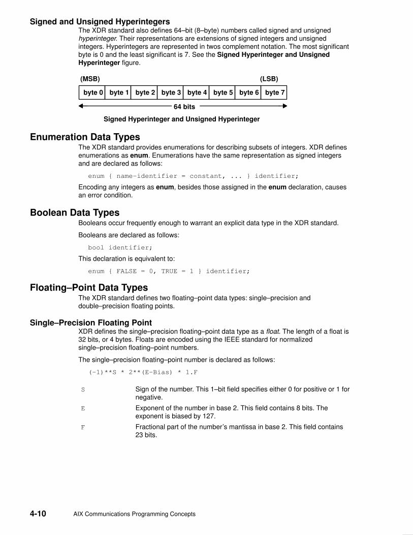
4-10 AIX Communications Programming Concepts
Signed and Unsigned HyperintegersThe XDR standard also defines 64–bit (8–byte) numbers called signed and unsignedhyperinteger. Their representations are extensions of signed integers and unsignedintegers. Hyperintegers are represented in twos complement notation. The most significantbyte is 0 and the least significant is 7. See the Signed Hyperinteger and UnsignedHyperinteger figure.
byte 0 byte 1 byte 2 byte 3
64 bits
(MSB) (LSB)
Signed Hyperinteger and Unsigned Hyperinteger
byte 4 byte 5 byte 6 byte 7
Enumeration Data TypesThe XDR standard provides enumerations for describing subsets of integers. XDR definesenumerations as enum. Enumerations have the same representation as signed integersand are declared as follows:
enum { name–identifier = constant, ... } identifier;
Encoding any integers as enum, besides those assigned in the enum declaration, causesan error condition.
Boolean Data TypesBooleans occur frequently enough to warrant an explicit data type in the XDR standard.
Booleans are declared as follows:
bool identifier;
This declaration is equivalent to:
enum { FALSE = 0, TRUE = 1 } identifier;
Floating–Point Data TypesThe XDR standard defines two floating–point data types: single–precision anddouble–precision floating points.
Single–Precision Floating PointXDR defines the single–precision floating–point data type as a float. The length of a float is32 bits, or 4 bytes. Floats are encoded using the IEEE standard for normalizedsingle–precision floating–point numbers.
The single–precision floating–point number is declared as follows:
(–1)**S * 2**(E–Bias) * 1.F
S Sign of the number. This 1–bit field specifies either 0 for positive or 1 fornegative.
E Exponent of the number in base 2. This field contains 8 bits. Theexponent is biased by 127.
F Fractional part of the number’s mantissa in base 2. This field contains23 bits.
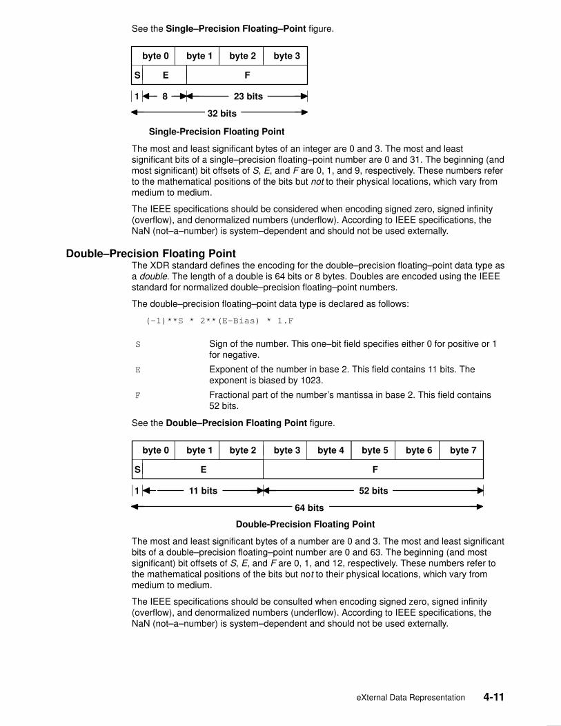
eXternal Data Representation 4-11
See the Single–Precision Floating–Point figure.
byte 0 byte 1 byte 2 byte 3
32 bits
Single-Precision Floating Point
S E F
1 23 bits 8
The most and least significant bytes of an integer are 0 and 3. The most and leastsignificant bits of a single–precision floating–point number are 0 and 31. The beginning (andmost significant) bit offsets of S, E, and F are 0, 1, and 9, respectively. These numbers referto the mathematical positions of the bits but not to their physical locations, which vary frommedium to medium.
The IEEE specifications should be considered when encoding signed zero, signed infinity(overflow), and denormalized numbers (underflow). According to IEEE specifications, theNaN (not–a–number) is system–dependent and should not be used externally.
Double–Precision Floating PointThe XDR standard defines the encoding for the double–precision floating–point data type asa double. The length of a double is 64 bits or 8 bytes. Doubles are encoded using the IEEEstandard for normalized double–precision floating–point numbers.
The double–precision floating–point data type is declared as follows:
(–1)**S * 2**(E–Bias) * 1.F
S Sign of the number. This one–bit field specifies either 0 for positive or 1for negative.
E Exponent of the number in base 2. This field contains 11 bits. Theexponent is biased by 1023.
F Fractional part of the number’s mantissa in base 2. This field contains52 bits.
See the Double–Precision Floating Point figure.
byte 0 byte 1 byte 2 byte 3
64 bits
Double-Precision Floating Point
S E F
1 52 bits 11 bits
byte 4 byte 5 byte 6 byte 7
The most and least significant bytes of a number are 0 and 3. The most and least significantbits of a double–precision floating–point number are 0 and 63. The beginning (and mostsignificant) bit offsets of S, E, and F are 0, 1, and 12, respectively. These numbers refer tothe mathematical positions of the bits but not to their physical locations, which vary frommedium to medium.
The IEEE specifications should be consulted when encoding signed zero, signed infinity(overflow), and denormalized numbers (underflow). According to IEEE specifications, theNaN (not–a–number) is system–dependent and should not be used externally.

4-12 AIX Communications Programming Concepts
Opaque Data TypesThe XDR standard defines two types of opaque data: fixed–length and variable–lengthopaque data.
Fixed–Length Opaque DataXDR defines fixed–length uninterpreted data as opaque. Fixed–length opaque data isdeclared as follows:
opaque identifier[n];
The constant n is the static number of bytes necessary to contain the opaque data. If n isnot a multiple of 4, then the n bytes are followed by enough (0 to 3) residual 0 bytes, r, tomake the total byte count of the opaque object a multiple of 4. See the Fixed–LengthOpaque figure.
byte 0 byte n–1
n bytes
Fixed-Length Opaque
byte 1 0 0
. . .
. . .
. . .
r bytes
n+r (where (n+r) mod 4 = 0)
0 1 . . .
. . .
. . .
. . .
. . .
. . .
. . .. . .
Variable–Length Opaque DataXDR also defines variable–length uninterpreted data as opaque. Variable–length (counted)opaque data is defined as a sequence of n arbitrary bytes, numbered 0 through n–1.Opaque data is encoded as an unsigned integer and followed by the n bytes of thesequence.
Byte m of the sequence always precedes byte m+1, and byte 0 of the sequence alwaysfollows the sequence length (count). Enough (0 to 3) residual 0 bytes, r, are added to makethe total byte count a multiple of 4.
Variable–length opaque data is declared in one of the following forms:
opaque identifier<m>;
OR
opaque identifier<>;
The constant m denotes an upper bound for the number of bytes that the sequence cancontain. If m is not specified, as in the second declaration, it is assumed to be (2**32) – 1,which is the maximum length. The constant m would normally be found in a protocolspecification. See the Variable–Length Opaque figure.
n bytes
Variable-Length Opaque
r bytes
n+r (where (n+r) mod 4 = 0)
0 1
. . .
. . .
. . .
. . .
. . .
. . .. . .
byte 0 byte 1length n
3 4 5
n–1 00
2
4 bytes
Note: Encoding a length n that is greater than the maximum described in the protocolspecification causes an error.

eXternal Data Representation 4-13
Array Data TypesThe XDR standard defines two type of arrays: fixed–length and variable–length.
Fixed–Length ArrayFixed–length arrays of homogeneous elements are declared as follows:
type–name identifier[n];
Fixed–length arrays of elements are encoded by individually coding the elements of thearray in their natural order, 0 through n–1. Each element size is a multiple of 4 bytes.Although the elements are of the same type, they may have different sizes. For example, ina fixed–length array of strings, all elements are of the string type, yet each element varies inlength. See the Fixed–Length Array figure.
Fixed-Length Array
. . .
. . .
. . .element 0 element 1 element n–1
n elements
Variable–Length ArrayThe XDR standard provides counted byte arrays for encoding variable–length arrays ofhomogeneous elements. The array is encoded as the element count n (an unsignedinteger) followed by the encoding of each of the array’s elements, starting with element 0and progressing through element n–1.
Variable–length arrays are declared as follows:
type–name identifier<m>;
OR
type–name identifier<>;
The constant m specifies the maximum acceptable element count of an array. If m is notspecified, it is assumed to be (2**32) – 1. See the Variable–Length Array figure.
Variable-Length Array
0 1
. . .
. . .
. . .element 0 element 1n
32
4 bytes
element n–1
n elements
4
Note: Encoding a length n greater than the maximum described in the protocolspecification causes an error.
StringsThe XDR standard defines a string of n (numbered 0 through n–1) ASCII bytes to be thenumber n encoded as an unsigned integer and followed by the n bytes of the string. Byte mof the string always precedes byte m+1, and byte 0 of the string always follows the stringlength. If n is not a multiple of 4, then the n bytes are followed by enough (0 to 3) residualzero bytes, r, to make the total byte count a multiple of 4.
Counted byte strings are declared as one of the following:
string object<m>;
OR
string object<>;

4-14 AIX Communications Programming Concepts
The constant m denotes an upper bound of the number of bytes that a string may contain. Ifm is not specified, as in the second declaration, it is assumed to be (2**32) – 1, which is themaximum length. The constant m would normally be found in a protocol specification. Forexample, a filing protocol may state that a file name can be no longer than 255 bytes, asfollows:
string filename<255>;
See the Counted Byte String figure.
n bytes
Counted Byte String
r bytes
n+r (where (n+r) mod 4 = 0)
0 1
. . .
. . .
. . .
. . .
. . .
. . .. . .
byte 0 byte 1length n
3 4 5
n–1 00
2
4 bytes
Note: Encoding a length n greater than the maximum described in the protocolspecification causes an error.
StructuresUsing the primitive routines, the programmer can write unique XDR routines to describearbitrary data structures such as elements of arrays, arms of unions, or objects pointed tofrom other structures. The structures themselves may contain arrays of arbitrary elementsor pointers to other structures.
Structures are declared as follows:
struct {
component–declaration–A;
component–declaration–B;
...
} identifier;
In a structure, the components are encoded in the order of their declaration in the structure.Each component size is a multiple of four bytes, although the components may havedifferent sizes. See the Structure figure.
Structure
. . .
. . .
. . .component A component B

eXternal Data Representation 4-15
Discriminated UnionsA discriminated union is a union data structure that holds various objects, with one of theobjects identified directly by a discriminant. The discriminant is the first item to be serializedor deserialized. A discriminated union includes both a discriminant and a component. Thetype of discriminant is either integer, unsigned integer, or an enumerated type, such asbool. The component is selected from a set of types that are prearranged according to thevalue of the discriminant. The component types are called arms of the union. The arms of adiscriminated union are preceded by the value of the discriminant that implies theirencoding. See the ”Using XDR Discriminated Union Example”, on page 4-37.
Discriminated unions are declared as follows:
union switch (discriminant–declaration) {
case discriminant–value–A:
arm–declaration–A;
case discriminant–value–B:
arm–declaration–B;
...
default: default–declaration;
} identifier;
Each case keyword is followed by a legal value of the discriminant. The default arm isoptional. If an arm is not specified, a valid encoding of the union cannot take on unspecifieddiscriminant values. The size of the implied arm is always a multiple of four bytes.
The discriminated union is encoded as the discriminant, followed by the encoding of theimplied arm.
See the figure for a discriminated union.
Discriminated Union
discriminant implied arm
4 bytes
0 1 2 3
VoidsAn XDR void is a zero–byte quantity. Voids are used for describing operations that take nodata as input or output. Voids are also useful in unions, where some arms contain data andothers do not.
The declaration for a void follows:
void;
Voids are illustrated as follows:
++
| |
++
––><–– 0 bytes
ConstantsA constant is used to define a symbolic name for a constant, and it does not declare anydata. The symbolic constant can be used anywhere a regular constant is used.
The data declaration for a constant follows this form:
const name–identifier = n;
The following example defines a symbolic constant, DOZEN, that is equal to 12:
const DOZEN = 12;

4-16 AIX Communications Programming Concepts
Type DefinitionsA type definition (a typedef statement) does not declare any data, but serves to define newidentifiers for declaring data.
The syntax for a type definition is:
typedef declaration;
The new type name is the variable name in the declaration part of the type definition. Forexample, the following defines a new type called eggbox, using an existing type called egg:
typedef egg eggbox[DOZEN];
Variables declared using the new type name are equivalent to variables declared using theexisting type. For example, the following two declarations for the variable fresheggs areequivalent:
eggbox fresheggs;
egg fresheggs[DOZEN];
A type definition can also have the following form:
typedef <<struct, union, or enum definition>> identifier;
An alternative type definition form is preferred for structures, unions, and enumerations. Thetype definition form can be converted to the alternative form by removing the typedefkeyword and placing the identifier after the struct, union, or enum keyword, instead of atthe end. For example, here are the two ways to define the type bool:
enum bool { /* preferred alternative */
FALSE = 0,
TRUE = 1
};
OR
typedef enum {F=0, T=1} bool;
The first syntax is preferred because the programmer does not have to wait until the end ofa declaration to determine the name of the new type.
Optional DataOptional data is a type of union that occurs so frequently it has its own syntax. The optionaldata type is closely coordinated to the representation of recursive data structures by the useof pointers in high–level languages, such as C or Pascal. The syntax for pointers is thesame as that for C language.
The syntax for optional data is as follows:
type–name *identifier;
The declaration for optional data is equivalent to the following union:
union switch (bool opted) {
case TRUE:
type–name element;
case FALSE:
void;
} identifier;
Since bool opted can be interpreted as the length of the array, the declaration for optionaldata is also equivalent to the following variable–length array declaration:
type–name identifier<1>;
eXternal Data Representation 4-17
Optional data is very useful for describing recursive data structures such as linked lists andtrees. For example, the following defines a stringlist type that encodes lists of arbitrarylength strings:
struct *stringlist {
string item<>;
stringlist next;
};
The example can be equivalently declared as a union, as follows:
union stringlist switch (bool opted) {
case TRUE:
struct {
string item<>;
stringlist next;
} element;
case FALSE:
void;
};
The example can also be declared as a variable–length array, as follows:
struct stringlist<1> {
string item<>;
stringlist next;
};
Since both the union and the array declarations obscure the intention of the stringlist type,the optional data declaration is preferred.

4-18 AIX Communications Programming Concepts
List of XDR Programming References The list of eXternal Data Representation (XDR) programming references includes:
• XDR Library Filter Primitives
• XDR Library Non–Filter Primitives
• Examples
XDR Library Filter Primitives
xdr_array Translates between variable–length arrays and their correspondingexternal representations.
xdr_bool Translates between Booleans and their external representations.
xdr_bytes Translates between internal counted byte string arrays and theirexternal representations.
xdr_char Translates between C language characters and their externalrepresentations.
xdr_double Translates between C language double–precision numbers and theirexternal representations.
xdr_enum Translates between C language enumerations and their externalrepresentations.
xdr_float Translates between C language floats and their externalrepresentations.
xdr_int Translates between C language integers and their externalrepresentations.
xdr_long Translates between C language long integers and their externalrepresentations.
xdr_opaque Translates between opaque data and its external representation.
xdr_reference Provides pointer chasing within structures.
xdr_short Translates between C language short integers and their externalrepresentations.
xdr_string Translates between C language strings and their externalrepresentations.
xdr_u_char Translates between unsigned C language characters and theirexternal representations.
xdr_u_int Translates between C language unsigned integers and their externalrepresentations.
xdr_u_long Translates between C language unsigned long integers and theirexternal representations.
xdr_u_short Translates between C language unsigned short integers and theirexternal representations.
xdr_union Translates between discriminated unions and their externalrepresentations.
xdr_vector Translates between fixed–length arrays and their correspondingexternal representations.
xdr_void Supplies an XDR subroutine to the Remote Procedure Call (RPC)system without transmitting data.
xdr_wrapstring Calls the xdr_string subroutine.

eXternal Data Representation 4-19
XDR Library Non–Filter Primitives
xdr_destroy Destroys the XDR stream pointed to by the xdrs parameter.
xdr_free Deallocates or frees memory.
xdr_getpos Returns an unsigned integer that describes the current position inthe data stream.
xdr_inline Returns a pointer to an internal piece of the buffer of a stream,pointed to by the xdrs parameter.
xdr_pointer Provides pointer chasing within structures and serializes nullpointers.
xdr_setpos Changes the current position in the XDR stream.
xdrmem_create Initializes in local memory the XDR stream pointed to by the xdrsparameter.
xdrrec_create Provides an XDR stream that can contain long sequences ofrecords.
xdrrec_endofrecord Causes the current outgoing data to be marked as a record.
xdrrec_eof Checks the buffer for an input stream.
xdrrec_skiprecord Causes the position of an input stream to move to the beginning ofthe next record.
xdrstdio_create Initializes the XDR data stream pointed to by the xdrs parameter.
ExamplesPassing Linked Lists Using XDR Example, on page 4-27
Using an XDR Data Description Example, on page 4-30
Showing the Justification for Using XDR Example, on page 4-32
Using XDR Example, on page 4-34
Using XDR Array Examples, on page 4-35
Using an XDR Discriminated Union Example, on page 4-37
Showing the Use of Pointers in XDR Example, on page 4-38

4-20 AIX Communications Programming Concepts
XDR Library Filter Primitives The eXternal Data Representation (XDR) primitives are subroutines that define the basicand constructed data types. The XDR language provides programmers with a specificationfor uniform representations that includes filter primitives for basic and constructed datatypes. The basic data types include integers, enumerations, Booleans, hyperintegers,floating points, and void data. The constructed data types include strings, structures, bytearrays, arrays, opaque data, unions, and pointers.
The XDR standard translates both basic and constructed data types. For basic data types,XDR provides basic filter primitives that serialize information from the local host’srepresentation to the XDR representation and deserialize information from the XDRrepresentation to the local host’s representation. For constructed data types, XDR providesconstructed filter primitives that allow the use of basic data types, such as integers andfloating–point numbers, to create more complex constructs such as arrays anddiscriminated unions.
Remote Procedure Calls (RPCs) use XDR to establish uniform representations for datatypes to transfer the call message data between machines. Although the XDR constructsresemble the C programming language, C language constructs define the code forprograms. XDR, however, standardizes the representation of data types directly in theprogramming code.
XDR Basic Filter PrimitivesThe XDR primitives are subroutines that define the basic and constructed data types. Thebasic data type filter primitives include the following:
• Number filter primitives
• Floating–point filter primitives
• Enumeration filter primitives
• No–data filter primitives
Number Filter PrimitivesThe XDR library provides basic filter primitives that translate between types of numbers andtheir external representations. The XDR number filters cover signed and unsigned integers,as well as signed and unsigned short and long integers.
The subroutines for the XDR number filters are:
xdr_int Translates between C language integers and their externalrepresentations.
xdr_u_int Translates between C language unsigned integers and their externalrepresentations.
xdr_long Translates between C language long integers and their externalrepresentations.
xdr_u_long Translates between C language unsigned long integers and theirexternal representations.
xdr_short Translates between C language short integers and their externalrepresentations.
xdr_u_short Translates between C language unsigned short integers and theirexternal representations.
eXternal Data Representation 4-21
Floating–Point Filter PrimitivesThe XDR library provides primitives that translate between floating–point data and theirexternal representations. Floating–point data encodes an integer with an exponent. Floatsand double–precision numbers compose floating–point data.
Note: Numbers are represented as IEEE standard floating points. Subroutines may failwhen decoding IEEE representations into machine–specific representations, or viceversa.
The subroutines for the XDR floating–point filters are:
xdr_double Translates between C language double–precision numbers and theirexternal representations.
xdr_float Translates between C language floats and their externalrepresentations.
Enumeration Filter PrimitivesThe XDR library provides a primitive for generic enumerations based on the assumption thata C enumeration value (enum) has the same representation. There is a specialenumeration in XDR known as the Boolean.
The subroutines for the XDR library enumeration filters are:
xdr_bool Translates between Booleans and their external representations.
xdr_enum Translates between C language enumerations and their externalrepresentations.
Passing No DataSometimes an XDR subroutine must be supplied to the RPC system, but no data is requiredor passed. The XDR library provides the following primitive for this function:
xdr_void Supplies an XDR subroutine to the RPC system without transmittingdata.
XDR Constructed Filter PrimitivesThe XDR filter primitives are subroutines that define the basic and constructed data types.Constructed data type filters allow complex data types to be created from basic data types.Constructed data types require more parameters to perform more complicated functionsthan do basic data types. Memory management is an example of a more complicatedfunction that can be performed with the constructed primitives. Memory is allocated whendeserializing data with the xdr_decode subroutine. Memory is deallocated through thexdr_free subroutine.
The constructed data–type filter primitives include the following:
• String filter primitives
• Array filter primitives
• Opaque data filter primitives
• Pointers to structures
• Discriminated unions

4-22 AIX Communications Programming Concepts
String Filter PrimitivesA string is a constructed filter primitive that consists of a sequence of bytes terminated by anull byte. The null byte does not figure into the length of the string. Externally, strings arerepresented by a sequence of ASCII characters. Internally, XDR uses the char *designation to represent pointers to strings.
The XDR library includes primitives for the following string routines:
xdr_string Translates between C language strings and their externalrepresentations.
xdr_wrapstring Calls the xdr_string subroutine.
Array Filter PrimitivesArrays are constructed filter primitives and can be either generic arrays or byte arrays. TheXDR library provides filter primitives for handling both types of arrays.
Generic Arrays
Generic arrays consist of arbitrary elements. Generic arrays are handled in much the sameway as byte arrays, which handle a subset of generic arrays where the size of the arbitraryelements is 1, and their external descriptions are predetermined. The primitive for genericarrays requires an additional parameter to define the size of the element in the array and tocall an XDR subroutine to encode or decode each element in the array.
The XDR library includes the following subroutines for generic arrays:
xdr_array Translates between variable–length arrays and theircorresponding external representations.
xdr_vector Translates between fixed–length arrays and their correspondingexternal representations.
Byte Arrays
The XDR library provides a primitive for byte arrays. Although similar to strings, byte arraysdiffer by having a byte count. That is, the length of the array is set by an unsigned integer.They also differ in that byte arrays are not terminated with a null character. External andinternal representations of byte arrays are the same.
The XDR library includes the following subroutine for byte arrays:
xdr_bytes Translates between counted byte string arrays and theirexternal representations.
Opaque–Data Filter PrimitivesOpaque data is composed of bytes of a fixed size that are not interpreted as they passthrough the data streams. Opaque data bytes, such as handles, are passed between serverand client without being inspected by the client. The client uses the data as it is and thenreturns it to the server. By definition, the actual data contained in the opaque object is notportable between computers.
The XDR library includes the following subroutine for opaque data:
xdr_opaque Translates between opaque data and its externalrepresentation.

eXternal Data Representation 4-23
Primitive for Pointers to StructuresThe XDR library provides a primitive for pointers so that structures referenced within otherstructures can be easily serialized, deserialized, and freed. The XDR library includes thefollowing subroutine for pointers to structures:
xdr_reference Provides pointer chasing within structures.
Primitive for Discriminated UnionsA discriminated union is a C language union, which is an object that holds several datatypes. One arm of the union is an enumeration value, or discriminant, that holds a specificobject to be processed over the system first. The discriminant is an enumeration value(enum_t).
The XDR library includes the following subroutine for discriminated unions:
xdr_union Translates between discriminated unions and their externalrepresentations.

4-24 AIX Communications Programming Concepts
XDR Non–Filter Primitives The eXternal Data Representation (XDR) nonfilter primitives are used to create, manipulate,implement, and destroy XDR data streams. These primitives allow programmers to destroya data stream (freeing its private structure) for example, or change a data stream position.
Creating and Using XDR Data StreamsXDR data streams are obtained by calling creation subroutines that take argumentsspecifically designed to the properties of the stream. There are existing XDR data streamsfor serializing or deserializing data in standard input and output streams, memory streams,and record streams.
Note: Remote Procedure Call (RPC) clients do not have to create XDR streams becausethe RPC system creates and passes these streams to the client.
The types of data streams include standard I/O streams, memory streams, and recordstreams.
Standard I/O StreamsXDR data streams serialize and deserialize standard input and output by calling thestandard I/O creation subroutine to initialize the XDR data stream pointed to by the xdrsparameter.
The XDR library includes the following subroutine for standard I/O data streams:
xdrstdio_create Initializes the XDR data stream pointed to by the xdrsparameter.
Memory StreamsXDR data streams serialize and deserialize data from memory by calling the XDR memorycreation subroutine to initialize in local memory the XDR stream pointed to by the xdrsparameter. In RPC, the User Datagram Protocol (UDP) Internet Protocol (IP)implementation uses this subroutine to build entire call–and–reply messages in memorybefore sending a message to the recipient.
The XDR library includes the following subroutine for memory data streams:
xdrmem_create Initializes in local memory the XDR stream pointed to by thexdrs parameter.
Record StreamsRecord streams are XDR streams built on top of record fragments, which are built onTCP/IP streams. TCP/IP is a connection protocol for transporting large streams of data atone time, instead of transporting a single data packet at a time.
Record streams are primarily used to make connections between remote procedure callsand TCP. They can also be used to stream data into or out of normal files.
XDR provides the following subroutines for use with record streams:
xdrrec_create Provides an XDR stream that can contain long sequences ofrecords.
xdrrec_endofrecord Causes the current outgoing data to be marked as a record.
xdrrec_eof Checks the buffer for an input stream that identifies the end offile (EOF).
xdrrec_skiprecord Causes the position of an input stream to move to the beginningof the next record.

eXternal Data Representation 4-25
Manipulating an XDR Data StreamXDR provides the following subroutines for describing and changing data stream position:
xdr_getpos Returns an unsigned integer that describes the current positionof the data stream.
xdr_setpos Changes the current position of the data stream.
Implementing an XDR Data StreamProgrammers can create and implement XDR data streams. The following example showsthe abstract data types (XDR handle) required. The example contains operations beingapplied to the stream, an operation vector for the implementation, and two private fields foruse by the implementation.
enum xdr_op { XDR_ENCODE=0, XDR_DECODE=1, XDR_FREE=2 };
typedef struct {
enum xdr_op x_op;
struct xdr_ops {
bool_t (*x_getlong) ();
boot_t (*x_putlong) ();
boot_t (*x_getbytes) ();
boot_t (*x_putbytes) ();
u_int (*x_getpostn) ();
boot_t (*x_setpostn) ();
caddr_t (*x_inline) ();
VOID (*x_destroy) ();
} *XOp;
caddr_t x_public;
caddr_t x_private;
caddr_t x_base;
int x_handy;
} XDR;
The following parameters are pointers to XDR stream manipulation subroutines:
x_destroy Frees private data structures.
x_getbytes Gets bytes from the data stream.
x_getlong Gets long integer values from the data stream.
x_getpostn Returns stream offset.
x_inline Points to internal data buffer, which can be used for any purpose.
x_putbytes Puts bytes into the data stream.
x_putlong Puts long integer values into the data stream.
x_setpostn Repositions offset.
XOp Specifies the current operation being performed on the stream. Thisfield is important to the XDR primitives. However, the stream’simplementation does not depend on the value of this parameter.

4-26 AIX Communications Programming Concepts
The following fields are specific to a stream’s implementation:
x_base Contains position information in the data stream that is private to theuser implementation.
x_handy Contains extra information, as necessary.
x_public Specifies user data that is private to the stream’s implementation and isnot used by the XDR primitive.
x_private Points to the private data.
Destroying an XDR Data StreamThe following subroutine destroys a specific XDR data stream:
xdr_destroy Destroys the XDR data stream pointed to by the xdrs parameter, freeingthe private data structures allocated to the stream.
The use of the XDR data stream handle is undefined after it is destroyed.

eXternal Data Representation 4-27
Passing Linked Lists Using XDR Example Linked lists of arbitrary length can be passed using eXternal Data Representation (XDR). Tohelp illustrate the functions of the XDR routine for encoding, decoding, or freeing linked lists,this example creates a data structure and defines its associated XDR routine.
The ”Using XDR Example”, on page 4-34 presents a C data structure and its associatedXDR routines for an individual’s gross assets and liabilities. The example is duplicatedbelow:
struct gnumbers {
long g_assets;
long g_liabilities;
};
bool_t
xdr_gnumbers (xdrs, gp)
XDR *xdrs;
struct gnumbers *gp;
{
if (xdr_long (xdrs, &(gp–>g_assets)))
return (xdr_long (xdrs, &( gp–>g_liabilities)));
return(FALSE);
}
xdrs Points to the XDR data stream handle.
gp Points to the address of the structure that provides the data to or fromthe XDR stream.
For implementing a linked list of such information, a data structure could be constructed asfollows:
struct gnumbers_node {
struct gnumbers gn_numbers;
struct gnnumbers_node *gn_next;
};
typedef struct gnumbers_node *gnumbers_list;
The head of the linked list can be thought of as the data object; that is, the head is notmerely a convenient shorthand for a structure. Similarly, the gn_next field indicateswhether or not the object has terminated. However, if the object continues, the gn_nextfield also specifies the address where it continues. The link addresses carry no usefulinformation when the object is serialized.
The XDR data description of this linked list can be described by the recursive declaration ofthe gnumbers_list field, as follows:
struct gnumbers {
int g_assets;
int g_liabilities;
};
struct gnumbers_node {
gnumbers gn_numbers;
gnumbers_node *gn_next;
};
In the following description, the Boolean indicates if more data follows it. If the Boolean is aFalse value, it is the last data field of the structure. If it is a True value, it is followed by agnumbers structure and, recursively, by a gnumbers_list. The C declaration has noBoolean explicitly declared in it (though the gn_next field implicitly carries the information),while the XDR data description has no pointer explicitly declared in it.
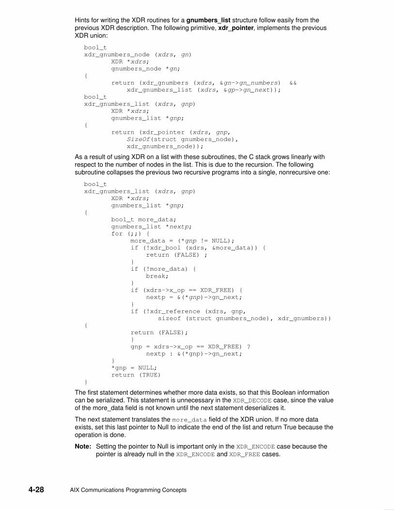
4-28 AIX Communications Programming Concepts
Hints for writing the XDR routines for a gnumbers_list structure follow easily from theprevious XDR description. The following primitive, xdr_pointer, implements the previousXDR union:
bool_t
xdr_gnumbers_node (xdrs, gn)
XDR *xdrs;
gnumbers_node *gn;
{
return (xdr_gnumbers (xdrs, &gn–>gn_numbers) &&
xdr_gnumbers_list (xdrs, &gp–>gn_next));
bool_t
xdr_gnumbers_list (xdrs, gnp)
XDR *xdrs;
gnumbers_list *gnp;
{
return (xdr_pointer (xdrs, gnp,
SizeOf(struct gnumbers_node),
xdr_gnumbers_node));
As a result of using XDR on a list with these subroutines, the C stack grows linearly withrespect to the number of nodes in the list. This is due to the recursion. The followingsubroutine collapses the previous two recursive programs into a single, nonrecursive one:
bool_t
xdr_gnumbers_list (xdrs, gnp)
XDR *xdrs;
gnumbers_list *gnp;
{
bool_t more_data;
gnumbers_list *nextp;
for (;;) {
more_data = (*gnp != NULL);
if (!xdr_bool (xdrs, &more_data)) {
return (FALSE) ;
}
if (!more_data) {
break;
}
if (xdrs–>x_op == XDR_FREE) {
nextp = &(*gnp)–>gn_next;
}
if (!xdr_reference (xdrs, gnp,
sizeof (struct gnumbers_node), xdr_gnumbers))
{
return (FALSE);
}
gnp = xdrs–>x_op == XDR_FREE) ?
nextp : &(*gnp)–>gn_next;
}
*gnp = NULL;
return (TRUE)
}
The first statement determines whether more data exists, so that this Boolean informationcan be serialized. This statement is unnecessary in the XDR_DECODE case, since the valueof the more_data field is not known until the next statement deserializes it.
The next statement translates the more_data field of the XDR union. If no more dataexists, set this last pointer to Null to indicate the end of the list and return True because theoperation is done.
Note: Setting the pointer to Null is important only in the XDR_ENCODE case because thepointer is already null in the XDR_ENCODE and XDR_FREE cases.

eXternal Data Representation 4-29
Next, if the direction is XDR_FREE, the value of the nextp field is set to indicate the locationof the next pointer in the list. This step dereferences the gnp field to find the location of thenext item in the list. After the next statement, the storage pointed to by gnp is freed and nolonger valid. This step is not taken for all directions because, in the XDR_DECODE direction,the value of the gnp field will not be set until the next statement.
The next statement translates the data in the node using the xdr_reference primitive. Thexdr_reference subroutine is similar to the xdr_pointer subroutine, used previously, but itdoes not send over the Boolean indicating whether there is more data. The program usesthe xdr_reference subroutine instead of the xdr_pointer subroutine because theinformation is already translated by XDR. Notice that the XDR subroutine passed is not thesame type as an element in the list. The subroutine passed is xdr_gnumbers, fortranslating gnumbers, but each element in the list is actually of the gnumbers_node type.The xdr_gnumbers_gnode subroutine is not passed because it is recursive. The programinstead uses xdr_gnumbers, which translates all nonrecursive portions.
Note: This method works only if the gn_numbers field is the first item in each element, sothat their addresses are identical when passed to the xdr_reference primitive.
Finally, the program updates the gnp field to point to the next item in the list. If the directionis XDR_FREE, it is set to the previously saved value. Otherwise, the program dereferencesthe gnp field to get the proper value. Though harder to understand than the recursiveversion, this nonrecursive subroutine is far less likely to cause errors in the C stack. Thenonrecursive subroutine also runs more efficiently because much procedure call overheadhas been removed. For small lists, containing hundreds of items or less, the recursiveversion of the subroutine should be sufficient.

4-30 AIX Communications Programming Concepts
Using an XDR Data Description Example The following short eXternal Data Representation (XDR) data description of a file can beused to transfer files from one machine to another:
const MAXUSERNAME = 32; /* max length of a user name */
const MAXFILELEN = 65535; /* max length of a file */
const MAXNAMELEN = 255; /* max length of a file name */
/*
* Types of files:
*/
enum filekind {
TEXT = 0, /* ascii data */
DATA = 1, /* raw data */
EXEC = 2 /* executable */
};
/*
* File information, per kind of file:
*/
union filetype switch (filekind kind) {
case TEXT:
void; /* no extra information */
case DATA:
string creator<MAXNAMELEN>; /* data creator */
case EXEC:
string interpretor<MAXNAMELEN>; /* program interpretor */
};
/*
* A complete file:
*/
struct file {
string filename<MAXNAMELEN>; /* name of file */
filetype type; /* info about file */
string owner<MAXUSERNAME>; /* owner of file */
opaque data<MAXFILELEN>; /* file data */
};

eXternal Data Representation 4-31
If a user named john wants to store his sillyprog LISP program, which contains just thedata (quit), his file can be encoded as follows:
Offset Hex Bytes ASCII Description
0 00 00 00 09 ... Length of file name = 9
4 73 69 6c 6c sill File name characters
8 79 70 72 6f ypro ... and more characters ...
12 67 00 00 00 g... ... and 3 zero–bytes of fill
16 00 00 00 02 ... File type is EXEC = 2
20 00 00 00 04 ... Length of owner = 4
24 6c 69 73 70 lisp Interpretor characters
28 00 00 00 04 ... Length of owner = 4
32 6a 6f 68 6e john Owner characters
36 00 00 00 06 ... Length of file data = 6
40 28 71 75 69 (qui File data bytes ...
44 74 29 00 00 t).. ... and 2 zero–bytes of fill

4-32 AIX Communications Programming Concepts
Showing the Justification for Using XDR Example Consider two programs, writer and reader. The writer program is written as follows:
#include <stdio.h>
main() /* writer.c */
{
long i;
for (i = 0; i < 8; i++) {
if (fwrite((char *)&i, sizeof(i), 1, stdout) != 1) {
fprintf(stderr, ”failed!\n”);
exit(1);
}
}
exit(0);
}
The reader program is written as follows:
#include <stdio.h>
main() /* reader.c */
{
long i, j;
for (j = 0; j < 8; j++) {
if (fread((char *)&i, sizeof (i), 1, stdin) != 1) {
fprintf(stderr, ”failed!\n”);
exit(1);
}
printf(”%ld ”, i);
}
printf(”\n”);
exit(0);
}
The two programs appear to be portable because they pass lint checking and exhibit thesame behavior when executed on two different hardware architectures, such as an IBMmachine and a VAX machine.
Piping the output of the writer program to the reader program gives identical results on anIBM machine or a VAX machine, as follows:
ibm% writer | reader
0 1 2 3 4 5 6 7
ibm%
vax% writer | reader
0 1 2 3 4 5 6 7
vax%
The following output results if the first program produces data on an IBM machine and thesecond consumes data on a VAX machine:
ibm% writer | rsh vax reader
0 16777216 33554432 50331648 67108864 83886080 100663296
117440512
ibm%
Executing the writer program on the VAX machine and the reader program on the IBMmachine produces results identical to the previous example. These results occur becausethe byte ordering of long integers differs between the VAX machine and the IBM machine,even though word size is the same.
Note: The value 16777216 equals 224. When 4 bytes are reversed, the 1 winds up in the24th bit.
Data must be portable when shared by two or more machine types. Programs can be madedata–portable by replacing the read and write system calls with calls to the xdr_long
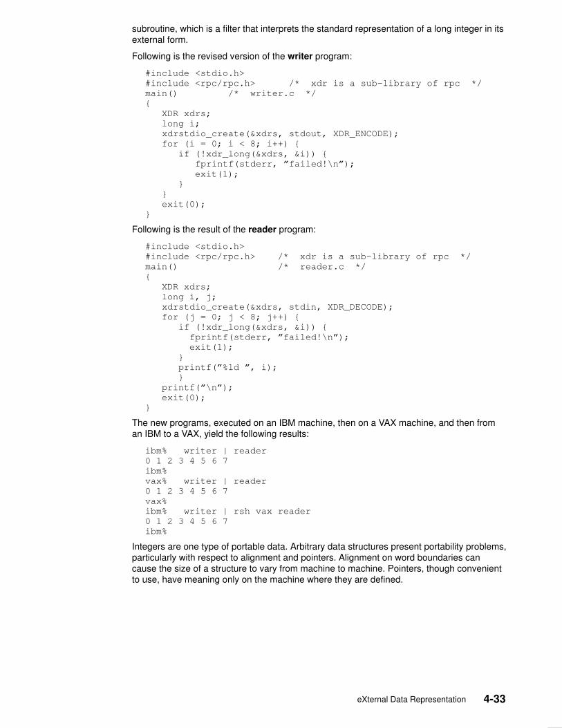
eXternal Data Representation 4-33
subroutine, which is a filter that interprets the standard representation of a long integer in itsexternal form.
Following is the revised version of the writer program:
#include <stdio.h>
#include <rpc/rpc.h> /* xdr is a sub–library of rpc */
main() /* writer.c */
{
XDR xdrs;
long i;
xdrstdio_create(&xdrs, stdout, XDR_ENCODE);
for (i = 0; i < 8; i++) {
if (!xdr_long(&xdrs, &i)) {
fprintf(stderr, ”failed!\n”);
exit(1);
}
}
exit(0);
}
Following is the result of the reader program:
#include <stdio.h>
#include <rpc/rpc.h> /* xdr is a sub–library of rpc */
main() /* reader.c */
{
XDR xdrs;
long i, j;
xdrstdio_create(&xdrs, stdin, XDR_DECODE);
for (j = 0; j < 8; j++) {
if (!xdr_long(&xdrs, &i)) {
fprintf(stderr, ”failed!\n”);
exit(1);
}
printf(”%ld ”, i);
}
printf(”\n”);
exit(0);
}
The new programs, executed on an IBM machine, then on a VAX machine, and then froman IBM to a VAX, yield the following results:
ibm% writer | reader
0 1 2 3 4 5 6 7
ibm%
vax% writer | reader
0 1 2 3 4 5 6 7
vax%
ibm% writer | rsh vax reader
0 1 2 3 4 5 6 7
ibm%
Integers are one type of portable data. Arbitrary data structures present portability problems,particularly with respect to alignment and pointers. Alignment on word boundaries cancause the size of a structure to vary from machine to machine. Pointers, though convenientto use, have meaning only on the machine where they are defined.

4-34 AIX Communications Programming Concepts
Using XDR Example Assume that a person’s gross assets and liabilities are to be exchanged among processes.Also, assume that these values are important enough to warrant their own data type:
struct gnumbers {
long g_assets;
long g_liabilities;
};
The corresponding eXternal Data Representation (XDR) routine describing this structurewould be:
bool_t /* TRUE is success, FALSE is failure */
xdr_gnumbers(xdrs, gp)
XDR *xdrs;
struct gnumbers *gp;
{
if (xdr_long(xdrs, &gp–>g_assets) &&
xdr_long(xdrs, &gp–>g_liabilities))
return(TRUE);
return(FALSE);
}
The xdrs parameter is neither inspected nor modified before being passed to thesubcomponent routines. However, programs should always inspect the return value of eachXDR routine call, and immediately give up and return False if the subroutine fails.
This example also shows that the bool_t type is declared as an integer whose only valuesare TRUE (1) and FALSE (0). This document uses the following definitions:
#define bool_t int
#define TRUE 1
#define FALSE 0
Keeping these conventions in mind, the xdr_gnumbers routine can be rewritten as follows:
xdr_gnumbers(xdrs, gp)
XDR *xdrs;
struct gnumbers *gp;
{
return(xdr_long(xdrs, &gp–>g_assets) &&
xdr_long(xdrs, &gp–>g_liabilities));
}

eXternal Data Representation 4-35
Using XDR Array Examples The following four examples illustrate eXternal Data Representation (XDR) arrays.
Example AA user on a networked machine can be identified by the machine name (using thegethostname subroutine), the user’s UID (using the geteuid subroutine), and the numbersof the group to which the user belongs (using the getgroups subroutine). A structure withthis information and its associated XDR subroutine could be coded as follows:
struct netuser {
char *nu_machinename;
int nu_uid;
u_int nu_glen;
int *nu_gids;
};
#define NLEN 255 /* machine names < 256 chars */
#define NGRPS 20 /* user can’t be in > 20 groups */
bool_t
xdr_netuser(xdrs, nup)
XDR *xdrs;
struct netuser *nup;
{
return(xdr_string(xdrs, &nup–>nu_machinename, NLEN) &&
xdr_int(xdrs, &nup–>nu_uid) &&
xdr_array(xdrs, &nup–>nu_gids, &nup–>nu_glen,
NGRPS, sizeof (int), xdr_int));
}
Example BTo code a subroutine to use fixed–length arrays, rewrite Example A as follows:
#define NLEN 255
#define NGRPS 20
struct netuser {
char *NUMachineName;
int nu_uid;
int nu_gids;
};
bool_t
xdr_netuser (XDRS, nup
XDR *xdrs;
struct netuser *nup;
{
int i;
if (!xdr_string(xdrs,&nup–>NUMachineName, NLEN))
return (FALSE);
if (!xdr_int (xdrs, &nup–>nu_uid))
return (FALSE);
for (i = 0; i < NGRPS; i+++) {
if (!xdr_int (xdrs, &nup–>nu_uids[i]))
return (FALSE);
}
return (TRUE);
}

4-36 AIX Communications Programming Concepts
Example CA party of network users can be implemented as an array in the netuser structure. Thedeclaration and its associated XDR routines are as follows:
struct party {
u_int p_len;
struct netuser *p_nusers;
};
#define PLEN 500 /* max number of users in a party */
bool_t
xdr_party(xdrs, pp)
XDR *xdrs;
struct party *pp;
{
return(xdr_array(xdrs, &pp–>p_nusers, &pp–>p_len, PLEN,
sizeof (struct netuser), xdr_netuser));
}
Example DThe main function’s well–known parameters, argc and argv, can be combined into astructure. An array of these structures can make up a history of commands. Thedeclarations and XDR routines can have the following syntax:
struct cmd {
u_int c_argc;
char **c_argv;
};
#define ALEN 1000 /* args cannot be > 1000 chars */
#define NARGC 100 /* commands cannot have > 100 args */
struct history {
u_int h_len;
struct cmd *h_cmds;
};
#define NCMDS 75 /* history is no more than 75 commands */
bool_t
xdr_wrap_string(xdrs, sp)
XDR *xdrs;
char **sp;
{
return(xdr_string(xdrs, sp, ALEN));
}
bool_t
xdr_cmd(xdrs, cp)
XDR *xdrs;
struct cmd *cp;
{
return(xdr_array(xdrs, &cp–>c_argv, &cp–>c_argc, NARGC,
sizeof (char *), xdr_wrap_string));
}
bool_t
xdr_history(xdrs, hp)
XDR *xdrs;
struct history *hp;
{
return(xdr_array(xdrs, &hp–>h_cmds, &hp–>h_len, NCMDS,
sizeof (struct cmd), xdr_cmd));
}

eXternal Data Representation 4-37
Using an XDR Discriminated Union Example If the type of a union can be an integer, string (a character pointer), or gnumbersstructure, and the union and its current type are declared in a structure, the followingdeclaration applies:
enum utype { INTEGER=1, STRING=2, GNUMBERS=3 };
struct u_tag {
enum utype utype; /* the union’s discriminant */
union {
int ival;
char *pval;
struct gnumbers gn;
} uval;
};
The following constructs and eXternal Data Representation (XDR) procedure serialize anddeserialize the discriminated union:
struct xdr_discrim u_tag_arms[4] = {
{ INTEGER, xdr_int },
{ GNUMBERS, xdr_gnumbers }
{ STRING, xdr_wrap_string },
{ __dontcare__, NULL }
/* always terminate arms with a NULL xdr_proc */
}
bool_t
xdr_u_tag(xdrs, utp)
XDR *xdrs;
struct u_tag *utp;
{
return(xdr_union(xdrs, &utp–>utype, &utp–>uval,
u_tag_arms, NULL));
}
The xdr_gnumbers subroutine is presented in the ”Passing Linked Lists Using XDRExample”, on page 4-27. The xdr_wrap_string subroutine is presented in Example D of”Example Using an XDR Array”, on page 4-36. The default arms parameter to the xdr_unionparameter is NULL in this example. Therefore, the value of the union’s discriminant maylegally take on only values listed in the u_tag_arms array. This example also demonstratesthat the elements of the arms array do not need to be sorted.
The values of the discriminant may be sparse (though not in this example). It is goodpractice assigning explicit integer values to each element of the discriminant’s type. Thispractice documents the external representation of the discriminant and guarantees thatdifferent C compilers emit identical discriminant values.

4-38 AIX Communications Programming Concepts
Showing the Use of Pointers in XDR Example If a structure contains a person’s name and a pointer to a gnumbers structure, which in turnspecifies the person’s gross assets and liabilities, the structure can be written as follows:
struct pgn {
char *name;
struct gnumbers *gnp;
};
The corresponding eXternal Data Representation (XDR) routine for this structure is:
bool_t
xdr_pgn(xdrs, pp)
XDR *xdrs;
struct pgn *pp;
{
if (xdr_string(xdrs, &pp–>name, NLEN) &&
xdr_reference(xdrs, &pp–>gnp,
sizeof(struct gnumbers), xdr_gnumbers))
return(TRUE);
return(FALSE);
}

Network Computing System 5-1
Chapter 5. Network Computing System
The Network Computing System (NCS) is an implementation of the Network ComputingArchitecture that distributes computer processing tasks across resources in either a singlenetwork or several interconnected networks (an internet), which may include a variety ofcomputers and programming environments.
This chapter discusses two key NCS components:
• Remote Procedure Call Runtime Library
• The Location Broker

5-2 AIX Communications Programming Concepts
Remote Procedure Call Runtime Library The Remote Procedure Call (RPC) run–time library, included in the /usr/lib/libnck.a library,contains the routines, tables, and data that support the communication of RPCs betweenclients and servers.
RPC run–time routines are responsible for transmitting RPC packets between the client andserver stubs (program modules that transfer RPCs and responses between a client and aserver).
RoutinesThe RPC run–time library contains routines that are normally used only by clients (clientroutines), some that are normally used only by servers (server routines), and others thatboth clients and servers can use (conversion routines).
Client RoutinesThe client and its stub use handles as temporary location identifiers to represent the objectand the server to the RPC run–time routines. The object or server is linked with its specificlocation through a process called binding.
Manual binding occurs when the client makes the RPC library handle management callsdirectly. Automatic binding occurs when the client stub calls a routine (written by theapplication developer) that makes all of the client’s calls to the RPC run–time routines.
The RPC run–time routines that are called by clients include routines that either createhandles or manage their binding state. In addition, one routine sends and receives packets.
Server RoutinesThe RPC run–time routines that are called by servers initialize the server, except for oneroutine that identifies the object to which a client has requested access.
Most of the server routines in the RPC run–time library initialize the server so that it canrespond to client requests for one or more interfaces. In the server code, routines should beincluded to do the following:
• Create one or more sockets to which clients can send messages.
• Register each interface that the server exports.
• Begin listening for client requests.
The RPC run–time library provides two routines that create sockets. One creates a socketwith a well–known port while the other creates a socket with an opaque port number.
A single server can support several interfaces. It can also listen on several sockets at atime. Most servers use one socket for each address family. A server is not required to usedifferent sockets for different interfaces.
The server must register each interface that it exports with the RPC run–time library so thatthe run–time library can direct client calls to the procedures that implement the requestedoperations. The library also includes a routine to unregister an interface that the server nolonger exports.
Once the server creates sockets, registers its interfaces, and begins listening, it is notrequired to make additional calls to the initialization routines. However, a server can registerand unregister interfaces while it is running.
Conversion RoutinesThe RPC run–time library also provides two routines that convert between names andsocket addresses. These routines enable programs to use names rather than addresses toidentify server hosts.
Network Computing System 5-3
The Location Broker The Location Broker provides clients with information about the locations of objects andinterfaces. Servers register their socket addresses and the objects and interfaces to whichthey provide access with the Location Broker. Clients issue requests to the Location Brokerfor the locations of objects and interfaces they wish to access. The broker returns databaseentries that match an object, type, interface, or combination, as specified in the request.
The Location Broker also implements the Remote Procedure Call (RPC)message–forwarding mechanism. If a client sends a request for an interface to theforwarding port on a host, the Location Broker automatically forwards the request to theappropriate server on the host.
Location Broker ComponentsThe Location Broker consists of these interrelated components:
Local Location Broker (LLB)
An RPC server that maintains a database of information about objectsand interfaces located on the local host. The LLB provides access to itsdatabase for application programs and also provides the LocationBroker forwarding service. An LLB must run on any host that runs RPCservers. The LLB runs as the daemon program, llbd.
Global Location Broker (GLB)
An RPC server that maintains information about objects and interfacesthroughout the network or internet. The GLB can run as either the glbdor nrglbd daemon program. The glbd daemon supports replicatableGLB databases in the network; the nrglbd daemon does not.
Location Broker Client Agent
A set of library routines that application programs call to access LLBand GLB databases. Any client using Location Broker library routines isactually making calls to the client agent. The client agent interacts withLLBs and GLBs to provide access to their databases.

5-4 AIX Communications Programming Concepts
The Location Broker Software figure shows the relationships among applicationprograms, the Location Broker components, and the Location Broker databases.
LLB Database
Local Host
GLB
GLB Database
Remote Application
Client Agent
Remote Host
GLB HostLLB
Client Agent
Local Application
Location Broker Software
Location Broker DataEach entry in a Location Broker database contains information about an object and aninterface, and it contains the location of a server that exports the interface to the object. Therecords in a database entry are as follows:
Object UUID Specifies a universally unique identifier (UUID) of theobject.
Type UUID Identifies a unique identifier that specifies the type of theobject.
Interface UUID Indicates a unique identifier of the interface to the object.
Flag Specifies a flag that indicates if the object is global (andshould be registered in the GLB database).
Annotation Contains 64 characters of user–defined information.
Socket Address Length Specifies the length of the socket address field.
Socket Address Indicates the location of the server that exports the interfaceto the object.
Each database entry contains one object UUID, one interface UUID, and one socketaddress. This means a Location Broker database must have an entry for each possiblecombination of object, interface, and socket address. For example, the database must have10 entries for a server that does the following:
• Listens on two sockets, socket_a and socket_b.
• Exports interface_1 for object_x, object_y, and object_z.
• Exports interface_2 for object_p and object_q.
The server must make a total of 10 calls to the lb_$register routine to completely registerits interfaces and objects.
You can look up Location Broker information by using any combination of the object UUID,type UUID, and interface UUID as keys. You can also request the information from the GLBdatabase or from a particular LLB database. Therefore, you can obtain information about allobjects of a specific type, all hosts with a specific interface to an object, or even all objects

Network Computing System 5-5
and interfaces at a specific host. For example, you can find the addresses of all remotelyavailable array processors by looking up all entries with the arrayproc type.
Location Broker Client AgentThe Location Broker client agent is a set of library routines that applications use to accessand modify the LLB and GLB databases. When a program issues any Location Broker call,the call goes to the local host’s client agent. The client agent does the work to add, delete,or look up information in the appropriate Location Broker database.
The Client Agent and a Global Location Broker figure illustrates a typical case in which aclient requires a particular interface to a particular object, but does not know the location ofa server exporting the interface to the object. In this figure, an RPC server registers itselfwith the Location Broker by calling the client agent in its host (step 1a). The client agent,through the LLB, adds the registration information to the LLB database at the server host(not shown). The client agent also sends the information to the GLB (step1b). To locate theserver, the client issues a Location Broker lookup call (step 2a). The client agent on theclient host sends the lookup request to the GLB, which returns the server location throughthe client agent to the client (step 2b). Then, the client can use RPC calls to communicatedirectly with the located server (steps 3a and 3b).
1bRegisterObject
ClientAgent
Server
Object
1aRegisterObject
Global Location Broker
3aAccess object
Client2aLookupObjectClient
Agent
2bLookupObject
3b
Client Agent and a Global Location Broker
If a client knows the host where the object is located but does not know the port numberused by the server, the client agent can query the remote host’s LLB directly, as illustrated inthe Client Agent Performing a Lookup at a Known Host figure.
2Access Object
1bLookup Object LLB
RequestedObject
1aLookupObject
Client
ClientAgent
Client Agent Performing a Lookup at a Known Host

5-6 AIX Communications Programming Concepts
Local Location BrokerThe LLB, which runs as the llbd daemon, maintains a database of the objects andinterfaces exported by servers running on the host. In addition, it acts as a forwarding agentfor requests.
An llbd daemon must be running on hosts that run RPC servers. However, it isrecommended to run an llbd daemon on every host in the network or internet.
Local DatabaseThe database maintained by the LLB provides location information about interfaces on thelocal host. This information is used by both local and remote applications. To look upinformation in an LLB database, an application queries the LLB through a client agent. Forapplications on a local host, the client agent accesses the LLB database directly. Forapplications on a remote host, the remote client agent accesses the LLB database throughthe LLB process. You can also access the LLB database manually by using the lb_admincommand.
LLB Forwarding AgentThe LLB’s forwarding facility eliminates the need for a client to know the specific port aserver uses. It is intended to limit the number of well–known port numbers reserved forspecific purposes.
The forwarding agent listens on one well–known port for each address family. It forwardsany messages received to the local server that exports the requested object. Forwarding isparticularly useful when the requester of a service already knows the host on which theserver is running. For example, you do not need to assign a well–known port to a server thatreports load statistics, nor do you need to register the server with the GLB. Each suchserver registers only with its host’s LLB. Remote clients access the server by specifying theobject, the interface, and the host, but not a specific port, when making a RemoteProcedure Call.
Global Location BrokerThe Global Location Broker (GLB), which can run as either the glbd daemon or the nrglbddaemon, manages information about the objects and interfaces available to users on thenetwork. In an internet, at least one GLB must be running on each network.
The GLB database is accessed manually by using the lb_admin command. The lb_admincommand is useful to manually correct errors in the database. For example, if a serverstarts while the GLB is not running, you can manually enter the information for the server inthe GLB database. Similarly, if a server terminates abnormally without unregistering itself,you can use the lb_admin command to manually remove its entry from the GLB database.

Network Information Service 6-1
Chapter 6. Network Information Service
The NFS Network Information Service (NIS) is a distributed database system used todistribute system information on networked hosts. This chapter lists technical referencesources for programming NIS. See ”Network Information Service Overview” in AIX 4.3System Management Guide: Communications and Networks for information aboutmanaging NIS.

6-2 AIX Communications Programming Concepts
List of NIS Programming References The list of Network Information Service (NIS) references includes:
• Subroutines
• Files
See ”List of NIS Commands” in AIX 4.3 System Management Guide: Communications andNetworks for information about Network Information System NIS commands and daemons.
Subroutines
yp_all Transfers all of the key–value pairs from the NIS server to theclient as the entire map.
yp_bind Calls the ypbind daemon directly for processes that usebackup strategies when NIS is not available.
yp_first Returns the first key–value pair from the named NIS map inthe named domain.
yp_get_default_domain Gets the default domain of the node.
yp_master Returns the machine name of the NIS master server for amap.
yp_match Searches for the value associated with a key.
yp_next Returns each subsequent value it finds in the named NISmap until it reaches the end of the list.
yp_order Returns the order number for an NIS map that identifies whenthe map was built.
yp_unbind Manages socket descriptors for processes that accessmultiple domains.
yp_update Makes changes to the NIS map.
yperr_string Returns a pointer to an error message string.
ypprot_err Takes an NIS protocol error code as input and returns anerror code to be used as input to a yperr_string subroutine.
Files
ethers Lists Ethernet addresses of hosts on the network.
netgroup Lists the groups of users on the network.
netmasks Lists network masks used to implement Internet Protocolstandard subnetting.
publickey Stores public or secret keys from NIS maps.
updaters Contains a makefile for updating NIS maps.
xtab Lists directories that are currently exported.

Network Management 7-1
Chapter 7. Network Management
The Network Management facility meets programming needs by managing system networksthrough the use of Simple Network Management Protocol (SNMP) by network hosts toexchange information.
The following topics are discussed in this chapter:
• Simple Network Management Protocol, on page 7-2
• Management Information Base, on page 7-3
• Terminology Related to Management Information Base Variables, on page 7-6
• Working with Management Information Base Variables, on page 7-7
• Management Information Base Database, on page 7-8
• How a Manager Functions, on page 7-10
• How an Agent Functions, on page 7-11
• List of SNMP Programming References, on page 7-13
• SMUX Error Logging Subroutines Examples, on page 7-16
7-2 AIX Communications Programming Concepts
Simple Network Management Protocol The Simple Network Management Protocol (SNMP) is used by network hosts to exchangeinformation in the management of networks. SNMP is defined in several Requests forComments (RFCs) available from the Network Information Center at SRI International,Menlo Park, California.
The following RFCs define SNMP:
RFC 1155 Defines the structure of management information.
RFC 1157 Defines the SNMP to create requests for Management InformationBase (MIB) information and formatting responses.
RFC 1213 Defines the MIB for network management.
RFC 1227 Defines the SNMP multiplexing (SMUX) protocol for extending baseSNMP agents.
RFC 1228 Defines the Distributed Protocol Interface (DPI) for extending baseSNMP agents.
RFC 1229 Defines an extension to the interfaces table as defined in RFC 1213.
RFC 1231 Defines an extension to the interfaces table for token–ring devices.
RFC 1398 Defines an extension to the interfaces table as Ethernet devices.
RFC 1512 Defines an extension to the interfaces table for Fiber Distributed DataInterface (FDDI) devices.
SNMP network management is based on the familiar client–server model that is widely usedin Transmission Control Protocol/Internet Protocol (TCP/IP)–based network applications.Each managed host runs a process called an agent. The agent is a server process thatmaintains the MIB database for the host. Hosts that are involved in network managementdecision–making may run a process called a manager. A manager is a client application thatgenerates requests for MIB information and processes responses. In addition, a managermay send requests to agent servers to modify MIB information.

Network Management 7-3
Management Information Base The Management Information Base (MIB) is a database containing the information pertinentto network management. The database is conceptually organized as a tree. The upperstructure of this tree is defined in Requests for Comments (RFC) 1155 and RFC 1213. Theinternal nodes of the tree represent subdivision by organization or function. MIB variablevalues are stored in the leaves of this tree. Thus, every distinct variable value correspondsto a unique path from the root of the tree. The children of a node are numbered sequentiallyfrom left to right, starting at 1, so that every node in the tree has a unique name, whichconsists of the sequence of node numbers that comprise the path from the root of the treeto the node. The Example Section of an MIB Tree figure illustrates the relationship ofsections of the MIB tree.
(.)
ISO (1) CCITT (2) joint-iso-ccitt (3)
org (3)
dod (6)
internet (1)
mgmt (2)
Internet-standard MIB database
version-number (1)
...
...
...
... ...
Example Section of an MIB Tree
Here, the network management data for the Internet is stored in the subtree reached by thepath 1.3.6.1.2.1. This notation is the conventional way of writing the numeric path name,separating node numbers by periods. All variables defined in RFC 1213 have numericnames that begin with this prefix.
Note: Future versions of the Internet–standard MIB may have higher version numbers withvariable names distinct from earlier versions.

7-4 AIX Communications Programming Concepts
A typical variable value is stored as a leaf, as illustrated in the Leaves on an MIB Treefigure.
1.3.6.1.2.1
system (1)
sysObjectId (2)
sysUpTime (3)
(0)
Variable names:defined by RFC1155and RFC1213
Instance values: definedby the administrator ofthe host, in conformancewith RFC1157
sysDescr (1)
...
value
(0)value
(0)value
...
...
sysServices (7)
(0)value
Leaves on an MIB Tree
The MIB manager data associates the values of the variables with each uniquely namedinstance of a variable. For example, 1.3.6.1.2.1.1.1.0 is the unique name of the systemdescription, a text string describing the host’s operational environment. Because only onesuch string exists, the instance of the variable name 1.3.6.1.2.1.1.1 (which is denoted by a0) is reserved for this use only. Many other variables have multiple instances, as illustratedin the Multiple Instance Variables figure.
ipRouteEntry (1.3.6.1.2.1.4.21.1)
ipRouteAge (10)
(127.50.50.50) (255.25.50.75)
Variable names:defined by RFC1155and RFC1213
Instance values: definedby the administrator ofthe host, in conformancewith RFC1157
...
... valuevalue
Multiple Instance Variables

Network Management 7-5
Each variable containing information about a route has an instance that is simply theInternet Protocol (IP) address of the route’s destination. Other variables have more complexrules for forming instances. The variable name uniquely identifies a group of related data,while the variable instance is a unique name for a particular item within the group. Forexample, 1.3.6.1.2.1.4.21.1.10 is the name of the variable whose instances are route ages,while 1.3.6.1.2.1.4.21.1.10.127.50.50.50 is the name of the instance that contains the age ofthe route to a host with the IP address of 127.50.50.50.
For more information on Internet addresses and routing see ”Internet (IP) Addresses” and”TCP/IP Routing”in AIX 4.3 System Management Guide: Communications and Networks.

7-6 AIX Communications Programming Concepts
Terminology Related to Management Information BaseVariables
Requests for Comments (RFC) 1155 and 1213 define the Management Information Base(MIB) as an object–oriented database. Both RFCs refer to the node names as objectidentifiers. Most nodes also have descriptive textual names called object descriptors. Theobject descriptors are convenient aliases, but Simple Network Management Protocol(SNMP) request packets refer to variable instances only by object identifier. Variable namesand variable instances are both denoted by object identifiers or object descriptors. Todistinguish the four possible combinations unambiguously, the following non–RFCterminology is used here:
Terminology
Non–RFC Terminology RFC Terminology Example
Text–format variable name (denotes the descriptivetextual name of a variable)
Object descriptor of avariable
sysDescr
Numeric–format variablename (denotes a variable nameexpressed as a sequence ofdecimal numbers separatedby periods)
Object Identifier of avariable
”1.3.6.1.2.1.1.1
Text–format instance ID (denotes a text–formatvariable name qualified byan instance)
Object descriptor of avariable with an instanceappended
sysDescr.0
Numeric–format instance ID (denotes a numeric–formatvariable name qualified byan instance)
Object identifier of a variablewith an instance appended
”1.3.6.1.2.1.1.1.0
Instance IDs are variable names with an instance appended. A variable name refers to a setof related data, while an instance ID refers to a specific item from the set.
For information on the subroutines, see ”List of SNMP Agent Programming References”, onpage 7-13.

Network Management 7-7
Working with Management Information Base Variables The snmpinfo command is a simple Simple Network Management Protocol (SNMP)manager application tool that makes SNMP get, get–next, and set requests of SNMPagents. The snmpinfo command obtains its object descriptions of the ManagementInformation Base (MIB) variables (described by RFC 1213) from the /etc/mib.defs file.
You can add object definitions for MIB variables to the /etc/mib.defs file by using the mosycommand.
You can also add object definitions for experimental MIB modules orprivate–enterprise–specific MIB modules to the /etc/mib.defs file. This file is created by themosy command. You first must obtain the private MIB module from a vendor that supportsthose MIB variables.
Updating the /etc/mib.defs file to incorporate a vendor’s private or experimental MIB objectdefinitions can be done two ways. The first approach is to create a subfile and thenconcatenate that subfile to the existing MIB /etc/mib.defs file. To create the subfile for theprivate MIBs and update the /etc/mib.defs file, issue the following commands:
mosy –o /tmp/private.obj /tmp/private.my
cat /etc/mib.defs /tmp/private.obj > /tmp/mib.defs
cp /tmp/mib.defs /etc/mib.defs
A second approach recreates the /etc/mib.defs file with the mosy command:
mosy –o /etc/mib.defs /usr/lpp/snmpd/smi.my \
/usr/lpp/snmpd/mibII.my /tmp/private.my
The MIB object groups in the private MIB object definition module may have orderdependencies.
Remember the SNMP agent being queried must have these MIB variables implementedbefore it can return a value for the requested MIB variables.

7-8 AIX Communications Programming Concepts
Management Information Base Database Network management can be passive or active. Passive network management involves thecollection of statistical data to profile the network activity of each host. Every variable in theInternet–standard Management Information Base (MIB) has a value that can be queried andused for this purpose.
Active network management uses a subset of MIB variables that are designated read–write.When an Simple Network Management Protocol (SNMP) agent is instructed to modify thevalue of one of these variables, an action is taken on the agent’s host as a side effect. Forexample, a request to set the ifAdminStatus.3 variable to the value of 2 has the side effectof disabling the network adapter card whose ifIndex variable is set to a value of 3.
Requests to read or change variable values are generated by manager applications. Threekinds of requests exist:
get Returns the value of the specified variable instance.
get–next Returns the value of the variable instance following the specifiedinstance, a get–next request.
set Modifies the value of the specified variable instance.
Requests are encoded according to the ISO ASN.1 CCITT standard for data representation(ISO document DIS 8825). Each get request contains a list of pairs of variable instancesand variable values called the variable binding list. The variable values are empty when therequest is transmitted. The values are filled in by the receiving agent and the entire bindinglist is copied into a response packet for transmission back to the monitor. If the request is aset request, the request packet also contains a list of variable values. These values arecopied into the binding list when the response is generated. If an error occurs, the agentimmediately stops processing the request packet, copies the partially processed binding listinto the response packet, and transmits it with an error code and the index of the bindingthat caused the error.
get–next RequestThe get–next request deserves special consideration. It is designed to navigate the entireInternet–standard MIB subtree. Since all instance IDs are sequences of numbers, they canbe ordered.
The first eight instance IDs are:
sysDescr.0 1.3.6.1.2.1.1.1.0
sysObjectId.0 1.3.6.1.2.1.1.2.0
sysUpTime.0 1.3.6.1.2.1.1.3.0
sysContact.0 1.3.6.1.2.1.1.4.0
sysName.0 1.3.6.1.2.1.1.5.0
sysLocation.0 1.3.6.1.2.1.1.6.0
sysServices.0 1.3.6.1.2.1.1.7.0
ifNumber.0 1.3.6.1.2.1.2.1.0
A get–next request for a MIB variable instance returns a binding list containing the next MIBvariable instance in sequence and its associated value. For example, a get–next request forthe sysDescr.0 variable returns a binding list containing the pair (sysObjectId.0, Value). Aget–next request for the sysObjectId.0 variable returns a binding list containing the pair(sysUpTime.0, Value), and so forth.
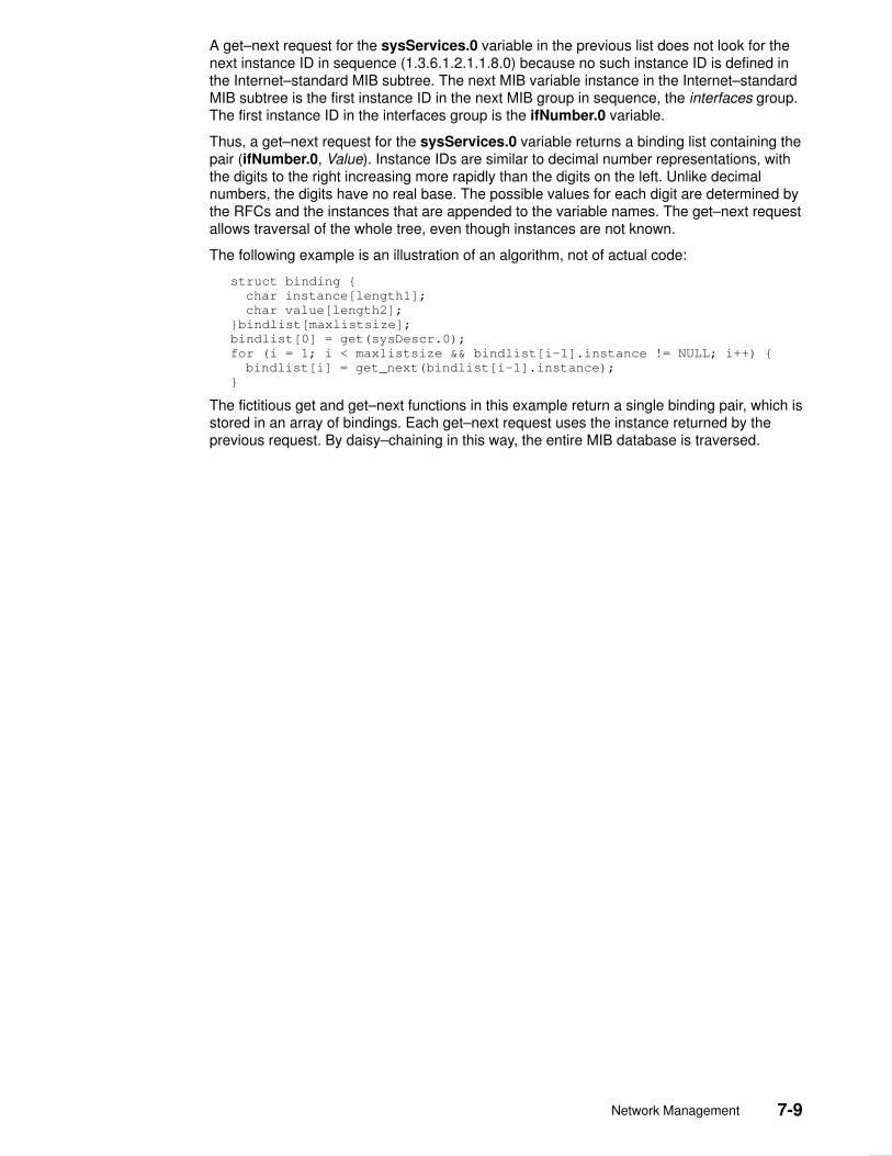
Network Management 7-9
A get–next request for the sysServices.0 variable in the previous list does not look for thenext instance ID in sequence (1.3.6.1.2.1.1.8.0) because no such instance ID is defined inthe Internet–standard MIB subtree. The next MIB variable instance in the Internet–standardMIB subtree is the first instance ID in the next MIB group in sequence, the interfaces group.The first instance ID in the interfaces group is the ifNumber.0 variable.
Thus, a get–next request for the sysServices.0 variable returns a binding list containing thepair (ifNumber.0, Value). Instance IDs are similar to decimal number representations, withthe digits to the right increasing more rapidly than the digits on the left. Unlike decimalnumbers, the digits have no real base. The possible values for each digit are determined bythe RFCs and the instances that are appended to the variable names. The get–next requestallows traversal of the whole tree, even though instances are not known.
The following example is an illustration of an algorithm, not of actual code:
struct binding {
char instance[length1];
char value[length2];
}bindlist[maxlistsize];
bindlist[0] = get(sysDescr.0);
for (i = 1; i < maxlistsize && bindlist[i–1].instance != NULL; i++) {
bindlist[i] = get_next(bindlist[i–1].instance);
}
The fictitious get and get–next functions in this example return a single binding pair, which isstored in an array of bindings. Each get–next request uses the instance returned by theprevious request. By daisy–chaining in this way, the entire MIB database is traversed.
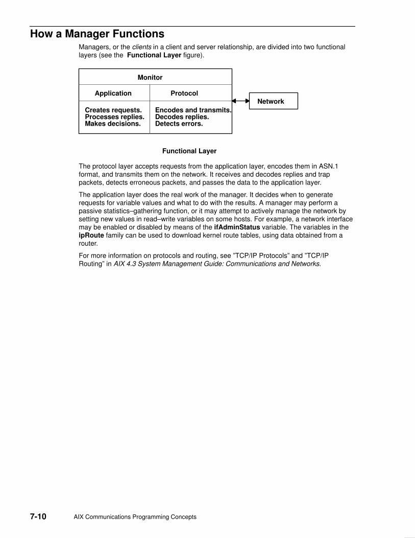
7-10 AIX Communications Programming Concepts
How a Manager Functions Managers, or the clients in a client and server relationship, are divided into two functionallayers (see the Functional Layer figure).
Monitor
Application
Creates requests.Processes replies.Makes decisions.
Protocol
Encodes and transmits.Decodes replies.Detects errors.
Network
Functional Layer
The protocol layer accepts requests from the application layer, encodes them in ASN.1format, and transmits them on the network. It receives and decodes replies and trappackets, detects erroneous packets, and passes the data to the application layer.
The application layer does the real work of the manager. It decides when to generaterequests for variable values and what to do with the results. A manager may perform apassive statistics–gathering function, or it may attempt to actively manage the network bysetting new values in read–write variables on some hosts. For example, a network interfacemay be enabled or disabled by means of the ifAdminStatus variable. The variables in theipRoute family can be used to download kernel route tables, using data obtained from arouter.
For more information on protocols and routing, see ”TCP/IP Protocols” and ”TCP/IPRouting” in AIX 4.3 System Management Guide: Communications and Networks.

Network Management 7-11
How an Agent Functions Agents are the servers in the client and server relationship. Agents listen on well–knownport 161 for request packets from managers. In addition to the protocol and applicationlayers, agents must also communicate with the operating system kernel. Most of theinformation in the Internet–standard MIB is maintained by kernel processes. The actionsassociated with a set request are often implemented as ioctl commands. In addition, thekernel may generate asynchronous notifications called traps. Some MIB information may bemanaged by another application, such as the gated daemon. The Agent Function figureoutlines the function of an agent.
Agent
Application
Processes requests.Creates replies.Sends trap packets.
Protocol
Decodes requests.Authenticates.Encodes replies.
Network
Kernel
Gets and saves values.Performs set actions.Generates traps.
gated Daemon
egpInMsgsegpInErrorsegpOutMsgsegpOutErrorsegpNeighStateegpNeighAddregpNeighAsegpNeighInMsgsegpNeighInErrsegpNeighOutMsgs
egpneighOutErrsegpNeighInErrMsgsegpNeighOutErrMsgsegpNeighStateUpsegpNeighStateDownsegpNeighIntervalHelloegpNeighIntervalPollegpNeighModeegpNeighEventTriggeregpAs
ipRouteDestipRouteIfIndexipRouteMetric1ipRouteMetric2ipRouteMetric3ipRouteMetric4ipRouteNextHopipRouteTypeipRouteProtoipRouteAgeipRouteMaskipRouteMetric5ipRouteInfo
Agent Function
One of the tasks of the protocol layer is to authenticate requests. This is optional and not allagents implement this task. If the protocol layer authenticates requests, the communityname included in every request packet is used to determine what access privileges thesender has. The community name might be used to reject all requests (if it is an unknownname), restrict the sender’s view of the database, or reject set requests from some senders.A manager might belong to many different communities, each of which may have a differentset of access privileges granted by the agents. A manager might generate or forwardrequests for other processes, using different community names for each.

7-12 AIX Communications Programming Concepts
TrapsThe agent may generate asynchronous event notifications called traps. For example, if aninterface adapter fails, the kernel may detect this and cause the agent to generate a trap toindicate the link is down (in some implementations, the agent may detect the condition).Also, other applications may generate traps. For example, in addition to the gated requesttypes shown in the Agent Function figure, the gated daemon generates anegpNeighborLoss trap whenever it puts an Exterior Gateway Protocol (EGP) neighbor intothe down state. The agent itself generates traps (coldStart, warmStart) when it initializesand when authentication fails (authenticationFailure). Each agent has a list of hosts towhich traps should be sent. The hosts are assumed to be listening on well–known port 162for trap packets.
For more information on EGP, see ”Exterior Gateway Protocol” in AIX 4.3 SystemManagement Guide: Communications and Networks.

Network Management 7-13
List of SNMP Agent Programming References The list of Simple Network Management Protocol (SNMP) programming referencesincludes:
• Programming Commands
• Files and File Formats
• SMUX Subroutines
Refer to the AIX Commands Reference for information about the system commands.
Programming Commands
mosy Converts the ASN.1 definitions of Structure andIdentification of Management Information (SMI) andManagement Information Base (MIB) modules into anobject definition file for the snmpinfo command.
snmpinfo Requests or modifies values of MIB variables managed byan SNMP agent.
Files and File Formats
mib.defs Defines the MIB variables the SNMP agent shouldrecognize and handle. The format of the /etc/mib.defs fileis required by the snmpinfo command.
mibII.my Defines the ASN.1 definitions for the MIB variables asdefined in RFC 1213.
smi.my Defines the ASN.1 definitions by which the SMI is definedas in RFC 1155.
snmpd.conf Defines a sample configuration file for the snmpd agent.
ethernet.my Defines the ASN.1 definitions for the MIB variables definedin RFC 1398.
fddi.my Defines the ASN.1 definitions for the MIB variables definedin RFC 1512.
generic.my Defines the ASN.1 definitions for the MIB variables definedin RFC 1229.
ibm.my Defines the ASN.1 definitions for the IBM enterprise sectionof the MIB tree.
token–ring.my Defines the ASN.1 definitions for the MIB variables definedin RFC 1231.
unix.my Defines the ASN.1 definitions for a set of MIB variables formemory buffer (mbuf) statistics, SNMP multiplexing(SMUX) peer information, and various other information.
view.my Defines the ASN.1 definitions for the SNMP access list andview tables.
snmpd.peers Defines a sample peers file for the snmpd agent.

7-14 AIX Communications Programming Concepts
SMUX Subroutines
getsmuxEntrybyidentity Retrieves SMUX peers by object identifier.
getsmuxEntrybyname Retrieves SMUX peers by name.
isodetailor Initializes variables for various logging facilities.
_ll_log Reports errors to log files.
ll_dbinit Reports errors to log files.
ll_hdinit Reports errors to log files.
ll_log Reports errors to log files.
o_generic Encodes values retrieved from the MIB into the specifiedvariable binding.
o_igeneric Encodes values retrieved from the MIB into the specifiedvariable binding.
o_integer Encodes values retrieved from the MIB into the specifiedvariable binding.
o_ipaddr Encodes values retrieved from the MIB into the specifiedvariable binding.
o_number Encodes values retrieved from the MIB into the specifiedvariable binding.
o_specific Encodes values retrieved from the MIB into the specifiedvariable binding.
o_string Encodes values retrieved from the MIB into the specifiedvariable binding.
ode2oid Returns a static pointer to the object identifier. Ifunsuccessful, the NULLOID value is returned.
oid2ode Takes an object identifier and returns its dot–notationdescription as a string.
oid2prim Encodes an object identifier structure into a presentationelement.
oid_cmp Manipulates the object identifier structure.
oid_cpy Manipulates the object identifier structure.
oid_extend Extends the base /usr/lib/libisode.a library subroutines.
oid_free Manipulates the object identifier structure.
oid_normalize Extends and adjusts the values of the object identifierstructure entries for the base /usr/lib/libisode.a librarysubroutines.
prim2oid Decodes an object identifier from a presentation element.
readobjects Allows an SMUX peer to read the MIB variable structure.
s_generic Sets the value of the MIB variable in the database.
smux_close Ends communication with the SNMP agent.
smux_error Creates a readable string from information found in thesmux_errno global variable.
smux_free_tree Frees the object tree when an SMUX tree is unregistered.
smux_init Initiates the Transmission Control Protocol (TCP) socketthat the SMUX agent uses and clears the basic SMUX datastructures.
smux_register Registers a section of the MIB tree with the SNMP agent.
smux_response Sends a response to a SNMP agent.

Network Management 7-15
smux_simple_open Sends the open protocol data unit (PDU) to the SNMPdaemon.
smux_trap Allows the SMUX peer to send traps to the SNMP agent.
smux_wait Waits for a message from the SNMP agent.
sprintoid Manipulates the object identifier structure.
str2oid Manipulates the object identifier structure.
text2oid Converts a text string into an object identifier.
text2obj Converts a text string into an object.
text2inst Retrieves instances of variables from a character string.
name2inst Retreives instances of variables from various forms of data.
next2inst Retreives instances of variables from various forms of data.
nextot2inst Retreives instances of variables from various forms of data.

7-16 AIX Communications Programming Concepts
SMUX Error Logging Subroutines Examples The advise and adios subroutines are example subroutines created to illustrate how theSNMP multiplexing (SMUX) _ll_log logging subroutine can be used. The adios and advisesample subroutines are in the unixd.c and sampled.c sample programs.
The adios subroutine exits on a fatal error. This subroutine sends a fatal message to the logfile and exits. If needed, other functionality can be added to the subroutine to help the failingprogram exit cleanly.
The advise subroutine sends an advisory message to the log. This subroutine allows theprogrammer to specify the message logging event type.
adios Sample Subroutine/* Function: adios
*
* Inputs:
* what – the thing that went wrong
* fmt – the string to be printed in printf format (char*)
* variables – variable needed to fill in the fmt.
*
* Outputs: none
* Returns: none
*
* NOTE: The adios function calls the logging function with the
* variables above and a LLOG_FATAL error code. The function then
* exits with a return code of 1, thereby terminating the sampled
* process.
*/
#ifndef lint
void adios (va_list)
va_dcl
{
va_list ap;
va_start (ap);
_ll_log (pgm_log, LLOG_FATAL, ap); /*Prints to the log*/
/*specified by pgm_log.a*/
/* Fatal error */
va_end (ap);
_exit (1);
}
#else
/* VARAGS */
void adios (what,fmt)
char *what,
*fmt;
{
adios (what, fmt);
}
#endif
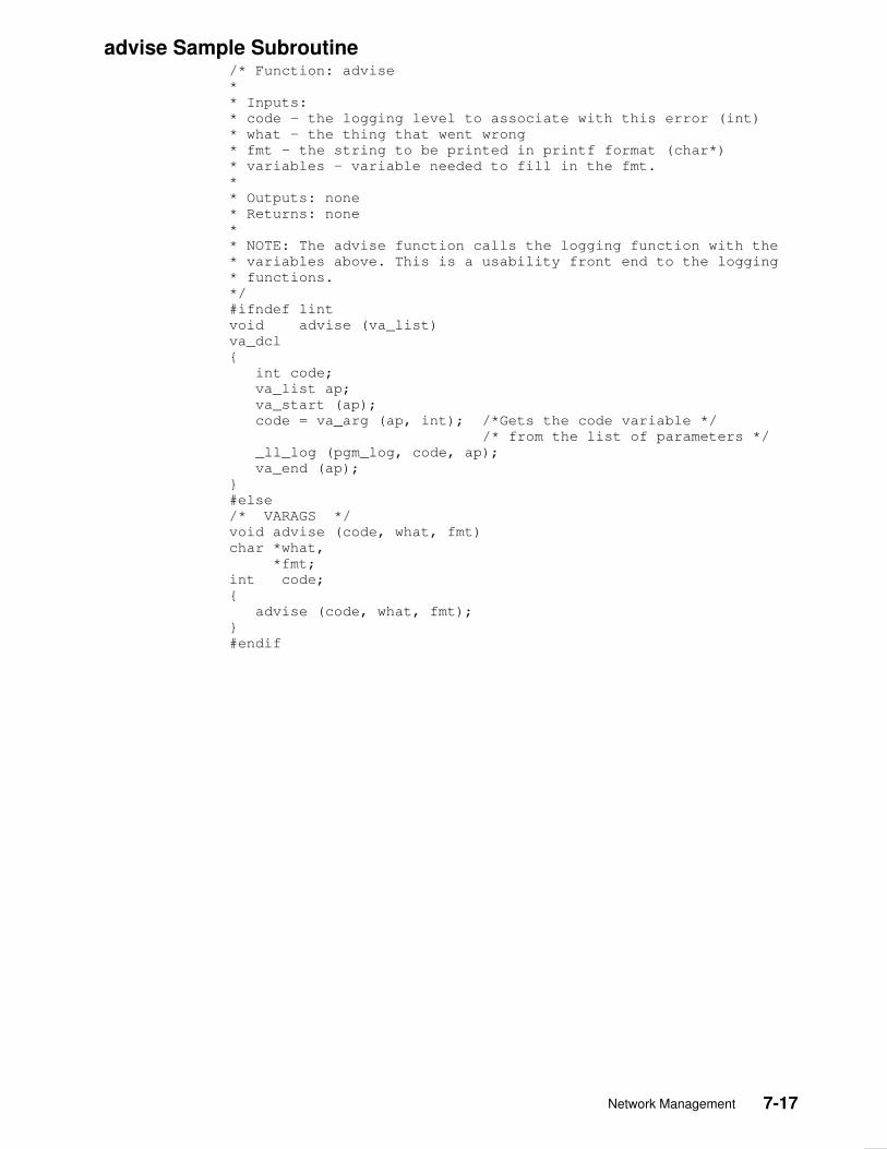
Network Management 7-17
advise Sample Subroutine/* Function: advise
*
* Inputs:
* code – the logging level to associate with this error (int)
* what – the thing that went wrong
* fmt – the string to be printed in printf format (char*)
* variables – variable needed to fill in the fmt.
*
* Outputs: none
* Returns: none
*
* NOTE: The advise function calls the logging function with the
* variables above. This is a usability front end to the logging
* functions.
*/
#ifndef lint
void advise (va_list)
va_dcl
{
int code;
va_list ap;
va_start (ap);
code = va_arg (ap, int); /*Gets the code variable */
/* from the list of parameters */
_ll_log (pgm_log, code, ap);
va_end (ap);
}
#else
/* VARAGS */
void advise (code, what, fmt)
char *what,
*fmt;
int code;
{
advise (code, what, fmt);
}
#endif

7-18 AIX Communications Programming Concepts
Remote Procedure Call 8-1
Chapter 8. Remote Procedure Call
Remote Procedure Call (RPC) is a protocol that provides the high–level communicationsparadigm used in the operating system. RPC presumes the existence of a low–leveltransport protocol, such as Transmission Control Protocol/Internet Protocol (TCP/IP) or UserDatagram Protocol (UDP), for carrying the message data between communicatingprograms. RPC implements a logical client–to–server communications system designedspecifically for the support of network applications.
This chapter provides the following information about programming RPC:
• RPC Model
• RPC Message Protocol
• RPC Authentication
• RPC Port Mapper Program
• Programming in RPC
• RPC Features
• RPC Language
• rpcgen Protocol Compiler
• List of RPC Programming References
The RPC protocol is built on top of the eXternal Data Representation (XDR) protocol, whichstandardizes the representation of data in remote communications. XDR converts theparameters and results of each RPC service provided.
The RPC protocol enables users to work with remote procedures as if the procedures werelocal. The remote procedure calls are defined through routines contained in the RPCprotocol. Each call message is matched with a reply message. The RPC protocol is amessage–passing protocol that implements other non–RPC protocols such as batching andbroadcasting remote calls. The RPC protocol also supports callback procedures and theselect subroutine on the server side.
A client is a computer or process that accesses the services or resources of anotherprocess or computer on the network. A server is a computer that provides services andresources, and that implements network services. Each network service is a collection ofremote programs. A remote program implements remote procedures. The procedures, theirparameters, and the results are all documented in the specific program’s protocol.
RPC provides an authentication process that identifies the server and client to each other.RPC includes a slot for the authentication parameters on every remote procedure call sothat the caller can identify itself to the server. The client package generates and returnsauthentication parameters. RPC supports various types of authentication such as the UNIXand Data Encryption Standard (DES) systems.
In RPC, each server supplies a program that is a set of remote service procedures. Thecombination of a host address, program number, and procedure number specifies oneremote service procedure. In the RPC model, the client makes a procedure call to send adata packet to the server. When the packet arrives, the server calls a dispatch routine,performs whatever service is requested, and sends a reply back to the client. The procedurecall then returns to the client.
The RPC interface is generally used to communicate between processes on differentworkstations in a network. However, RPC works just as well for communication betweendifferent processes on the same workstation.

8-2 AIX Communications Programming Concepts
The Port Mapper program maps RPC program and version numbers to a transport–specificport number. The Port Mapper program makes dynamic binding of remote programspossible.
To write network applications using RPC, programmers need a working knowledge ofnetwork theory. For most applications, an understanding of the RPC mechanisms usuallyhidden by the rpcgen command’s protocol compiler is also helpful. However, use of therpcgen command circumvents the need for understanding the details of RPC.

Remote Procedure Call 8-3
RPC Model The remote procedure call (RPC) model is similar to a local procedure call model. In thelocal model, the caller places arguments to a procedure in a specified location such as aresult register. Then, the caller transfers control to the procedure. The caller eventuallyregains control, extracts the results of the procedure, and continues execution.
RPC works in a similar manner, in that one thread of control winds logically through twoprocesses: the caller process and the server process. First, the caller process sends a callmessage that includes the procedure parameters to the server process. Then, the callerprocess waits for a reply message (blocks). Next, a process on the server side, which isdormant until the arrival of the call message, extracts the procedure parameters, computesthe results, and sends a reply message. The server waits for the next call message. Finally,a process on the caller receives the reply message, extracts the results of the procedure,and the caller resumes execution.
The Remote Procedure Call Flow figure illustrates the RPC paradigm.
ManagerProcedures
Client
Server StubClient Stub
RPC RuntimeLibrary
return
call
RPC RuntimeLibrary
Interface
Server processClient process
apparent flow
networkmessages
Remote Procedure Call Flow
return returncall call
callreturncall return
In the RPC model, only one of the two processes is active at any given time. Furthermore,this model is only an example. The RPC protocol makes no restrictions on the concurrencymodel implemented, and others are possible. For example, an implementation can chooseasynchronous Remote Procedure Calls so that the client can continue working while waitingfor a reply from the server. Additionally, the server can create a task to process incomingrequests and thereby remain free to receive other requests.
8-4 AIX Communications Programming Concepts
Transports and SemanticsThe RPC protocol is independent of transport protocols. How a message is passed fromone process to another makes no difference in RPC operations. The protocol deals onlywith the specification and interpretation of messages.
RPC does not try to implement any kind of reliability. The application must be aware of thetype of transport protocol underneath RPC. If the application is running on top of a reliabletransport, such as Transmission Control Protocol/Internet Protocol (TCP/IP), then most ofthe work is already done. If the application is running on top of a less–reliable transport,such as User Datagram Protocol (UDP), then the application must implement aretransmission and time–out policy, because RPC does not provide these services.
Due to transport independence, the RPC protocol does not attach specific semantics to theremote procedures or their execution. The semantics can be inferred from (and should beexplicitly specified by) the underlying transport protocol. For example, consider RPC runningon top of a transport such as UDP. If an application retransmits RPC messages after shorttime outs and receives no reply, the application infers that the procedure was executed zeroor more times. If the application receives a reply, the application infers that the procedurewas executed at least once.
A transaction ID is packaged with every RPC request. To ensure some degree ofexecute–at–most–once semantics, RPC allows a server to use the transaction ID to recall apreviously granted request. The server can then refuse to grant that request again. Theserver is allowed to examine the transaction ID only as a test for equality. The RPC clientmainly uses the transaction ID to match replies with requests. However, a client applicationcan reuse a transaction ID when transmitting a request.
When using a reliable transport such as TCP/IP, the application can infer from a replymessage that the procedure was executed exactly once. If the application receives no replymessage, the application cannot assume that the remote procedure was not executed.Even if a connection–oriented protocol like TCP/IP is used, an application still needs timeouts and reconnection to handle server crashes.
Transports besides datagram or connection–oriented protocols can also be used. Forexample, a request–reply protocol, such as Versatile Message Transaction Protocol(VMTP), is perhaps the most natural transport for RPC.
RPC in the Binding ProcessThe act of binding a client to a service is not part of the Remote Procedure Callspecification. This important and necessary function is left to higher–level software.However, the higher level software may use RPC in the binding process. The RPC portmapper program is an example of software that uses RPC.
The RPC protocol’s relationship to the binding software is similar to the relationship of thenetwork jump–subroutine instruction (JSR) to the loader (binder). The loader uses JSR toaccomplish its task. Similarly, the network uses RPC to accomplish the bind.
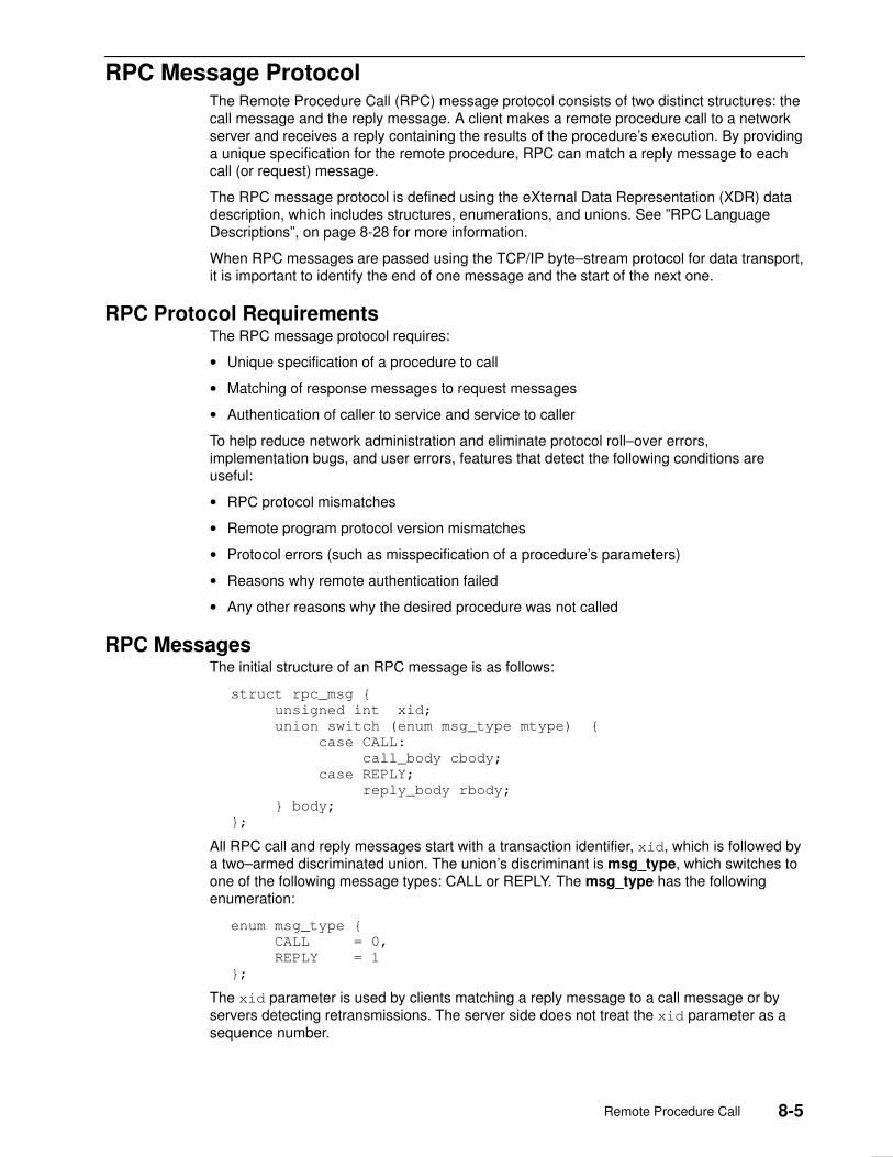
Remote Procedure Call 8-5
RPC Message Protocol The Remote Procedure Call (RPC) message protocol consists of two distinct structures: thecall message and the reply message. A client makes a remote procedure call to a networkserver and receives a reply containing the results of the procedure’s execution. By providinga unique specification for the remote procedure, RPC can match a reply message to eachcall (or request) message.
The RPC message protocol is defined using the eXternal Data Representation (XDR) datadescription, which includes structures, enumerations, and unions. See ”RPC LanguageDescriptions”, on page 8-28 for more information.
When RPC messages are passed using the TCP/IP byte–stream protocol for data transport,it is important to identify the end of one message and the start of the next one.
RPC Protocol RequirementsThe RPC message protocol requires:
• Unique specification of a procedure to call
• Matching of response messages to request messages
• Authentication of caller to service and service to caller
To help reduce network administration and eliminate protocol roll–over errors,implementation bugs, and user errors, features that detect the following conditions areuseful:
• RPC protocol mismatches
• Remote program protocol version mismatches
• Protocol errors (such as misspecification of a procedure’s parameters)
• Reasons why remote authentication failed
• Any other reasons why the desired procedure was not called
RPC MessagesThe initial structure of an RPC message is as follows:
struct rpc_msg {
unsigned int xid;
union switch (enum msg_type mtype) {
case CALL:
call_body cbody;
case REPLY;
reply_body rbody;
} body;
};
All RPC call and reply messages start with a transaction identifier, xid, which is followed bya two–armed discriminated union. The union’s discriminant is msg_type, which switches toone of the following message types: CALL or REPLY. The msg_type has the followingenumeration:
enum msg_type {
CALL = 0,
REPLY = 1
};
The xid parameter is used by clients matching a reply message to a call message or byservers detecting retransmissions. The server side does not treat the xid parameter as asequence number.

8-6 AIX Communications Programming Concepts
The initial structure of an RPC message is followed by the body of the message. The bodyof a call message has one form. The body of a reply message, however, takes one of twoforms, depending on whether a call is accepted or rejected by the server.
RPC Call MessageEach remote procedure call message contains the following unsigned integer fields touniquely identify the remote procedure:
• Program number
• Program version number
• Procedure number
The body of an RPC call message takes the following form:
struct call_body {
unsigned int rpcvers;
unsigned int prog;
unsigned int vers;
unsigned int proc;
opaque_auth cred;
opaque_auth verf;
1 parameter
2 parameter . . .
};
The parameters for this structure are:
rpcvers Specifies the version number of the RPC protocol. The value of thisparameter is 2 to indicate the second version of RPC.
prog Specifies the number that identifies the remote program. This is anassigned number represented in a protocol that identifies the programneeded to call a remote procedure. Program numbers are administeredby a central authority and documented in the program’s protocolspecification.
vers Specifies the number that identifies the remote program version. As aremote program’s protocols are implemented, they evolve and change.Version numbers are assigned to identify different stages of a protocol’sevolution. Servers can service requests for different versions of thesame protocol simultaneously.
proc Specifies the number of the procedure associated with the remoteprogram being called. These numbers are documented in the specificprogram’s protocol specification. For example, a protocol’s specificationcan list the read procedure as procedure number 5 or the writeprocedure as procedure number 12.
cred Specifies the credentials–authentication parameter that identifies thecaller as having permission to call the remote program. This parameteris passed as an opaque data structure, which means the data is notinterpreted as it is passed from the client to the server.
verf Specifies the verifier–authentication parameter that identifies the callerto the server. This parameter is passed as an opaque data structure,which means the data is not interpreted as it is passed from the client tothe server.
1 parameter Denotes a procedure–specific parameter.
2 parameter Denotes a procedure–specific parameter.
The client can send a broadcast packet to the network and wait for numerous replies fromvarious servers. The client can also send an arbitrarily large sequence of call messages in abatch to the server.

Remote Procedure Call 8-7
RPC Reply MessageThe RPC protocol for a reply message varies depending on whether the call message isaccepted or rejected by the network server.
The reply message to a request contains information to distinguish the following conditions:
• RPC executed the call message successfully.
• The remote implementation of RPC is not protocol version 2. The lowest and highestsupported RPC version numbers are returned.
• The remote program is not available on the remote system.
• The remote program does not support the requested version number. The lowest andhighest supported remote program version numbers are returned.
• The requested procedure number does not exist. This is usually a caller–side protocol orprogramming error.
The RPC reply message takes the following form:
enum reply_stat stat {
MSG_ACCEPTED = 0,
MSG_DENIED = 1
};
The enum reply_stat discriminant acts as a switch to the rejected or accepted replymessage forms.
The Reply to an Accepted RequestAn RPC reply message for a request accepted by the network server has the followingstructure:
struct accepted_reply areply {
opaque_auth verf;
union switch (enum accept_stat stat) {
case SUCCESS:
opaque results {0};
/* procedure specific results start here */
case PROG_MISMATCH:
struct {
unsigned int low;
unsigned int high;
} mismatch_info;
default:
void;
} reply_data;
};
The structures within the accepted reply are:
opaque_auth verf Authentication verifier generated by the server to identify itselfto the caller.
enum accept_stat A discriminant that acts as a switch between SUCCESS,PROG_MISMATCH, and other appropriate conditions.

8-8 AIX Communications Programming Concepts
The accept_stat enumeration data type has the following definitions:
enum accept_stat {
SUCCESS = 0, /* RPC executed successfully */
PROG_UNAVAIL = 1, /* remote has not exported program */
PROG_MISMATCH = 2, /* remote cannot support version # */
PROC_UNAVAIL = 3, /* program cannot support procedure */
GARBAGE_ARGS = 4, /* procedure cannot decode params */
};
The structures within the accept_stat enumeration data type are defined as follows:
SUCCESS RPC call is successful.
PROG_UNAVAIL The remote server has not exported the program.
PROG_MISMATCH The remote server cannot support the client’s version number.Returns the lowest and highest version numbers of the remoteprogram that are supported by the server.
PROC_UNAVAIL The program cannot support the requested procedure.
GARBAGE_ARGS The procedure cannot decode the parameters specified in thecall.
Note: An error condition can exist even when a call message is accepted by the server.
The Reply to a Rejected RequestA call message can be rejected by the server for two reasons: either the server is notrunning a compatible version of the RPC protocol, or there is an authentication failure.
An RPC reply message for a request rejected by the network server has the followingstructure:
struct rejected_reply rreply {
union switch (enum reject_stat stat) {
case RPC_MISMATCH:
struct {
unsigned int low;
unsigned int high;
} mismatch_info;
case AUTH_ERROR: enum auth_stat stat;
};
The enum reject_stat discriminant acts as a switch between RPC_MISMATCH andAUTH_ERROR. The rejected call message returns one of the following status conditions:
enum reject_stat {
RPC_MISMATCH = 0, /* RPC version number is not 2 */
AUTH_ERROR = 1, /* remote cannot authenticate caller */
};

Remote Procedure Call 8-9
RPC_MISMATCH The server is not running a compatible version of the RPC protocol. Theserver returns the lowest and highest version numbers available.
AUTH_ERROR The server refuses to authenticate the caller and returns a failure statuswith the value enum auth_stat. Authentication may fail because of bador rejected credentials, bad or rejected verifier, expired or replayedverifier, or security problems.
If the server does not authenticate the caller, AUTH_ERROR returns oneof the following conditions as the failure status:
enum auth_stat {
AUTH_BADCRED = 1, /* bad credentials
*/
AUTH_REJECTEDCRED = 2, /* begin new session
*/
AUTH_BADVERF = 3, /* bad verifier
*/
AUTH_REJECTEDVERF = 4, /* expired or replayed
*/
AUTH_TOOWEAK = 5, /* rejected for securi
ty*/
};
Marking Records in RPC MessagesWhen RPC messages are passed using the TCP/IP byte–stream protocol for data transport,it is important to identify the end of one message and the start of the next one. This is calledrecord marking (RM).
A record is composed of one or more record fragments. A record fragment is a four–byteheader, followed by 0 to 232 –1 bytes of fragment data. The bytes encode an unsignedbinary number, similar to XDR integers, in which the order of bytes is from highest to lowest.This binary number encodes a Boolean and an unsigned binary value of 31 bits.
The Boolean value is the highest–order bit of the header. A Boolean value of 1 indicates thelast fragment of the record. The unsigned binary value is the length, in bytes, of the datafragment.
Note: A protocol disagreement between client and server can cause remote procedureparameters to be unintelligible to the server.

8-10 AIX Communications Programming Concepts
RPC Authentication The caller may not want to identify itself to the server, and the server may not require an IDfrom the caller. However, some network services, such as the Network File System (NFS),require stronger security. Remote Procedure Call (RPC) authentication provides a certaindegree of security.
The following are part of RPC authentication:
• RPC Authentication Protocol
• NULL Authentication
• UNIX Authentication
• Data Encryption Standard (DES) Authentication
• DES Authentication Protocol
• Diffie–Hellman Encryption
RPC deals only with authentication and not with access control of individual services. Eachservice must implement its own access control policy and reflect this policy as returnstatuses in its protocol. The programmer can build additional security and access controlson top of the message authentication.
The authentication subsystem of the RPC package is open–ended. Different forms ofauthentication can be associated with RPC clients. That is, multiple types of authenticationare easily supported at one time. Examples of authentication types include UNIX, DES, andNULL. The default authentication type is none (AUTH_NULL).
RPC Authentication Protocol The RPC protocol provisions for authentication of the caller to the server, and vice versa,are provided as part of the RPC protocol. Every remote procedure call is authenticated bythe RPC package on the server. Similarly, the RPC client package generates and sendsauthentication parameters. The call message has two authentication fields: credentials andverifier. The reply message has one authentication field: response verifier.
The following RPC protocol specification defines as an opaque data type the credentials ofthe call message and the verifiers of both the call and reply messages:
enum auth_flavor {
AUTH_NULL = 0, AUTH_UNIX = 1,
AUTH_SHORT = 2,
AUTH_DES = 3
/* and more to be defined */
};
struct opaque_auth {
auth_flavor flavor;
opaque body<400>;
};
Any opaque_auth structure is an auth_flavor enumeration followed by bytes that areopaque to the RPC protocol implementation. The interpretation and semantics of the datacontained within the authentication fields are specified by individual, independentauthentication protocol specifications.
If authentication parameters are rejected, response messages state the reasons. A servercan support multiple types of authentication at one time.

Remote Procedure Call 8-11
NULL Authentication Sometimes, the RPC caller does not know its own identity or the server does not need toknow the caller’s identity. In these cases, the AUTH_NULL authentication type can be usedin both the call message and response messages. The bytes of the opaque_auth bodyare undefined. The opaque length should be 0.
UNIX Authentication A process calling a remote procedure might need to identify itself as it is identified on theUNIX system. The value of the credential’s discriminant of an RPC call message isAUTH_UNIX. The bytes of the credential’s opaque body encode the following structure:
struct auth_unix {
unsigned stamp;
string machinename;
unsigned uid;
unsigned gid;
unsigned gids;
};
The parameters in the structure are defined as follows:
stamp Specifies the arbitrary ID generated by the caller’s workstation.
machinename Specifies the name of the caller’s workstation. The name must notexceed 255 bytes in length.
uid Specifies the caller’s effective user ID.
gid Specifies the caller’s effective group ID.
gids Specifies the counted array of group IDs that contain the caller as amember. A maximum of 10 groups is allowed.
The verifier accompanying the credentials should be AUTH_NULL.
The value of the discriminant in the response verifier of the reply message from the server iseither AUTH_NULL or AUTH_SHORT. If the value is AUTH_SHORT, the bytes of theresponse verifier’s string encode an opaque structure. The new opaque structure can thenbe passed to the server in place of the original AUTH_UNIX credentials. The servermaintains a cache that maps shorthand opaque structures (passed back by way of anAUTH_SHORT–style response verifier) to the original credentials of the caller. The callersaves network bandwidth and server CPU time when the shorthand credentials are used.
Note: The server can eliminate, or flush, the shorthand opaque structures at any time. Ifthis happens, the RPC message will be rejected due to an AUTH_REJECTEDCREDauthentication error. The original AUTH_UNIX credentials can be used when thishappens.
UNIX Authentication on the Client Side When a caller creates a new RPC client handle, the authentication handle of the appropriatetransport is set to the default by the authnone_create subroutine. The default for an RPCauthentication handle is NULL. After creating the client handle, the client can select UNIXauthentication with the authunix_create routine. This routine creates an authenticationhandle with AIX permissions and causes each remote procedure call associated with thehandle to carry UNIX credentials.
Note: Authentication information can be destroyed with the auth_destroy subroutine.Authentication information should be destroyed if one is attempting to conservememory.
For more information, see the ”Using UNIX Authentication Example”, on page 8-41.

8-12 AIX Communications Programming Concepts
UNIX Authentication on the Server Side Dealing with authentication issues on the server side is more difficult than dealing with themon the client side. The caller’s RPC package passes the service dispatch routine a requestthat has an arbitrary authentication style associated with it. The server must then determinewhich style of authentication the caller used and whether the style is supported by the RPCpackage.
If the authentication parameter type is not suitable for the calling service, the servicedispatch routine calls the svcerr_weakauth routine to refuse the remote procedure call. It isnot customary for the server to check the authentication parameters associated withprocedure 0 (NULLPROC).
If the service does not have the requested protocol, the service dispatch returns a status foraccess denied. The svcerr_systemerr primitive is called to detect a system error that is notcovered by a service protocol.
Data Encryption Standard (DES) Authentication DES authentication offers more security features than UNIX authentication. For DESauthentication to work, the keyserv daemon must be running on both the server and clientmachines. The users at these workstations need public keys assigned in the public keydatabase by the person administering the network. Additionally, each user’s secret key mustbe decrypted using their keylogin command password.
DES authentication can handle the following UNIX problems:
• The naming scheme within UNIX authentication is UNIX–system oriented.
• UNIX authentication lacks a verifier, thereby allowing falsification of credentials.
For more information, see the ”DES Authentication Example”, on page 8-44.
DES Authentication Naming Scheme DES addresses the caller with a simple string of characters instead of an integer specific toa particular operating system. This string of characters is known as the caller’s networkname, or net name. The server is allowed to interpret the contents of the net name only toidentify the caller. Therefore, net names should be unique for each caller in the network.
Each operating system is responsible for implementing DES authentication to generateunique net names for calling on remote servers. Since operating systems can alreadydistinguish local users to their systems, extending this mechanism to the network is simple.
For example, a UNIX user at company xyz with a user ID of 515 might be assigned thefollowing net name: [email protected]. This net name contains three items that ensureuniqueness. First, only one naming domain in the Internet is called xyz.com. In this domainthere is only one UNIX user with user ID 515. Another user on another operating system,such as VMS, in the same naming domain can have the same user ID. However, two usersare distinguished by the operating system name. In this example, one user [email protected] and the other is [email protected].
The first field is actually a naming method rather than an operating system name. Currently,a one–to–one correspondence between naming methods and operating systems exists. If auniversal naming standard is agreed upon, the first field will become the name of thatstandard instead of an operating system name.
DES Authentication Verifiers Unlike UNIX authentication, DES authentication has a verifier that permits the server tovalidate the client’s credential and the client to validate the server’s credential. The contentof this verifier is primarily an encrypted time stamp. The time stamp is encrypted by theclient and decrypted by the server. If the time stamp is close to real time, then the clientencrypted it correctly. To encrypt the time stamp correctly, the client must have theconversation key of the RPC session. The client with the conversation key is the authenticclient.

Remote Procedure Call 8-13
The conversation key is a DES key that the client generates and includes in its first remoteprocedure call to the server. The conversation key is encrypted using a public key schemein the first transaction. The particular public key scheme used in DES authentication is theDiffie–Hellman system with 192–bit keys. For more information, see ”Diffie–HellmanEncryption”, on page 8-15.
For successful validation, both the client and the server need the same notion of currenttime. If network time synchronization cannot be guaranteed, the client can synchronize withthe server before beginning the conversation, perhaps by consulting the Internet TimeServer (TIME).
DES Authentication on the Server Side The method for determining the validity of a client’s time stamp depends on whichtransaction is under consideration. For the first transaction, the server checks only that thetime stamp has not expired. For subsequent transactions, the server verifies that the timestamp is greater than the previous time stamp from the same client, and that the time stamphas not expired. A time stamp has expired if the server’s time is later than the sum of theclient’s time stamp plus the client’s window. The sum of the time stamp plus the client’swindow can be thought of as the lifetime of the credential.
DES Authentication on the Client Side In the first transaction to the server, the client sends an encrypted item, the window verifier,that must equal the client’s window minus one, as an added check. Otherwise, the clientcould successfully send random data instead of the time stamp. Other values for thecredential are rejected by the server. If the window verifier is accepted by the server, theserver returns to the client a verifier equal to the encrypted time stamp, minus one second.If the client receives a different time stamp from the server, the client rejects it.
For subsequent transactions, the client’s time stamp is valid if it is greater than the previoustime stamp, and has not expired. A time stamp has expired if the server’s time is later thanthe sum of the client’s time stamp plus the client’s window. The sum of the time stamp plusthe client window can be thought of as the lifetime of the credential.
To use DES authentication, the programmer must set the client authentication handle usingthe authdes_create subroutine. This subroutine requires the network name of the owner ofthe server process, a lifetime for the credential, the address of the host with which tosynchronize, and the address of a DES encryption key to use for encrypting time stampsand data.
Nicknames The server’s DES authentication subsystem returns a nickname to the client in the verifierresponse to the first transaction. The nickname is an unsigned integer. The nickname islikely to be an index into a table on the server that stores each client’s net name, decryptedDES key, and window. The client can use the nickname in all subsequent transactionsinstead of passing its net name, encrypted DES key, and window each time. The nicknameis not required, but it saves time.
Clock Synchronization Although the client and server clocks are originally synchronized, they can lose thissynchronization. When this happens, the client RPC subsystem normally receives theRPC_AUTHERROR error message and should resynchronize.
A client can receive the RPC_AUTHERROR message even when the clocks aresynchronized. The message indicates that the server’s nickname table has been flushedeither because of the table’s size limitations or a server crash. To receive new nicknames,all clients must resend their original credentials to the server.

8-14 AIX Communications Programming Concepts
DES Authentication Protocol DES authentication has the following form of eXternal Data Representation (XDR)enumeration:
enum authdes_namekind {
ADN_FULLNAME = 0,
ADN_NICKNAME = 1
};
typedef opaque des_block[8];
const MAXNETNAMELEN = 255;
A credential is either a client’s full network name or its nickname. For the first transactionwith the server, the client must use its full name. For subsequent transactions, the client canuse its nickname. DES authentication protocol includes a 64–bit block of encrypted DESdata and specifies the maximum length of a network user’s name.
The authdes_cred union provides a switch between the full–name and nickname forms, asfollows:
union authdes_cred switch (authdes_namekind adc_namekind) {
case ADN_FULLNAME:
authdes_fullname adc_fullname;
case ADN_NICKNAME:
unsigned int adc_nickname;
};
The full name contains the network name of the client, an encrypted conversation key, andthe window. The window is actually a lifetime for the credential. The server can terminate aclient’s time stamp and not grant the request if the time indicated by the verifier time stampplus the window has expired. In the first transaction, the server confirms that the windowverifier is one second less than the window. To ensure that requests are granted only once,the server can require time stamps in subsequent requests to be greater than the client’sprevious time stamps.
The structure for a credential using the client’s full network name follows:
struct authdes_fullname {
string name<MAXNETNAMELEN>; /* name of client */
des_block key; /*PK encrypted conversation key*/
unsigned int window; /* encrypted window */
};
A time stamp encodes the time since midnight, January 1, 1970. The structure for the timestamp follows:
struct timestamp {
unsigned int seconds; /* seconds */
unsigned int useconds; /* and microseconds */
The client verifier has the following structure:
struct {
adv_timestamp; /* one DES block */
adc_fullname.window; /* one half DES block */
adv_winverf; /* one half DES block */
}
The window verifier is only used in the first transaction. In conjunction with the fullnamecredential, these items are packed into the above structure before being encrypted.
This structure is encrypted using CBC mode encryption with an input vector of 0. All othertime stamp encryptions use ECB mode encryption. The client’s verifier has the followingstructure:
struct authdes_verf_clnt {
timestamp adv_timestamp; /* encrypted timestamp */
unsigned int adv_winverf; /* encrypted window verifier */
};
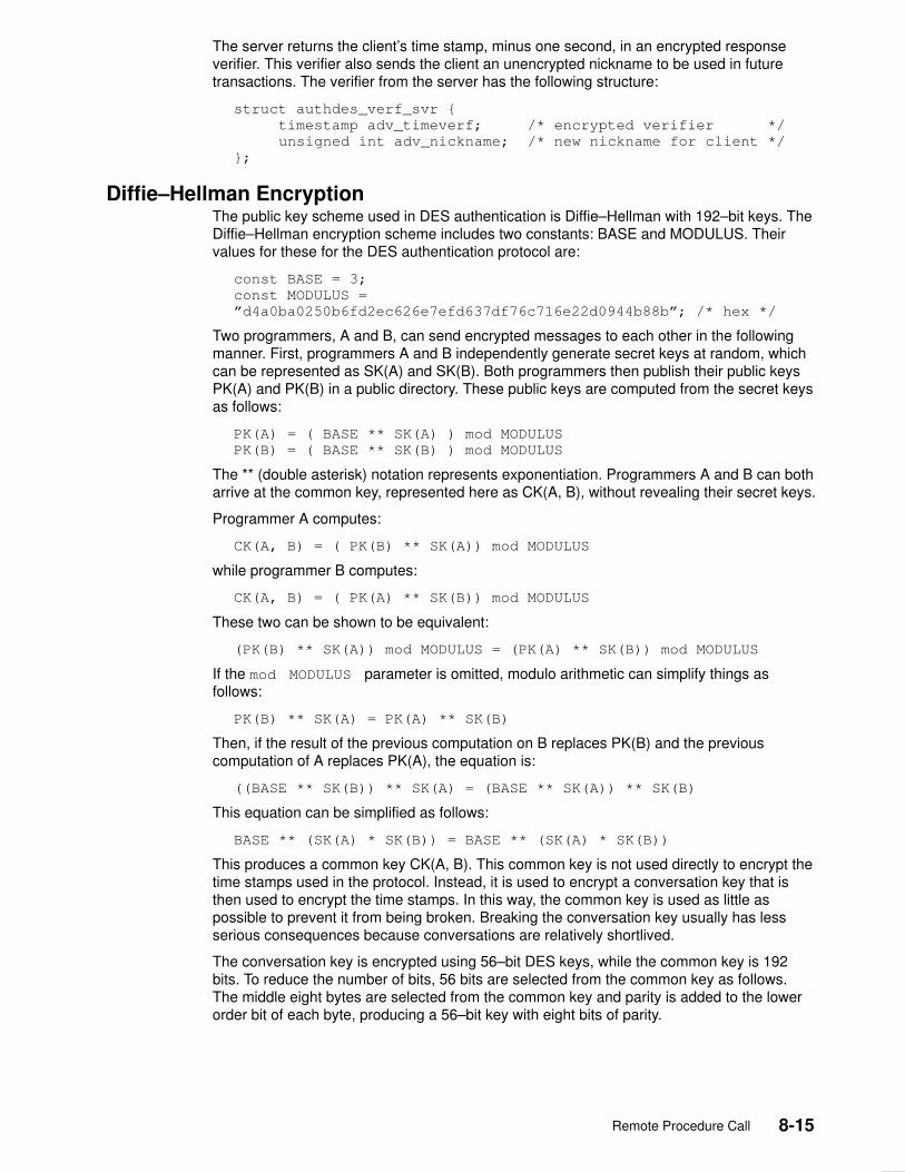
Remote Procedure Call 8-15
The server returns the client’s time stamp, minus one second, in an encrypted responseverifier. This verifier also sends the client an unencrypted nickname to be used in futuretransactions. The verifier from the server has the following structure:
struct authdes_verf_svr {
timestamp adv_timeverf; /* encrypted verifier */
unsigned int adv_nickname; /* new nickname for client */
};
Diffie–Hellman Encryption The public key scheme used in DES authentication is Diffie–Hellman with 192–bit keys. TheDiffie–Hellman encryption scheme includes two constants: BASE and MODULUS. Theirvalues for these for the DES authentication protocol are:
const BASE = 3;
const MODULUS =
”d4a0ba0250b6fd2ec626e7efd637df76c716e22d0944b88b”; /* hex */
Two programmers, A and B, can send encrypted messages to each other in the followingmanner. First, programmers A and B independently generate secret keys at random, whichcan be represented as SK(A) and SK(B). Both programmers then publish their public keysPK(A) and PK(B) in a public directory. These public keys are computed from the secret keysas follows:
PK(A) = ( BASE ** SK(A) ) mod MODULUS
PK(B) = ( BASE ** SK(B) ) mod MODULUS
The ** (double asterisk) notation represents exponentiation. Programmers A and B can botharrive at the common key, represented here as CK(A, B), without revealing their secret keys.
Programmer A computes:
CK(A, B) = ( PK(B) ** SK(A)) mod MODULUS
while programmer B computes:
CK(A, B) = ( PK(A) ** SK(B)) mod MODULUS
These two can be shown to be equivalent:
(PK(B) ** SK(A)) mod MODULUS = (PK(A) ** SK(B)) mod MODULUS
If the mod MODULUS parameter is omitted, modulo arithmetic can simplify things asfollows:
PK(B) ** SK(A) = PK(A) ** SK(B)
Then, if the result of the previous computation on B replaces PK(B) and the previouscomputation of A replaces PK(A), the equation is:
((BASE ** SK(B)) ** SK(A) = (BASE ** SK(A)) ** SK(B)
This equation can be simplified as follows:
BASE ** (SK(A) * SK(B)) = BASE ** (SK(A) * SK(B))
This produces a common key CK(A, B). This common key is not used directly to encrypt thetime stamps used in the protocol. Instead, it is used to encrypt a conversation key that isthen used to encrypt the time stamps. In this way, the common key is used as little aspossible to prevent it from being broken. Breaking the conversation key usually has lessserious consequences because conversations are relatively shortlived.
The conversation key is encrypted using 56–bit DES keys, while the common key is 192bits. To reduce the number of bits, 56 bits are selected from the common key as follows.The middle eight bytes are selected from the common key and parity is added to the lowerorder bit of each byte, producing a 56–bit key with eight bits of parity.

8-16 AIX Communications Programming Concepts
RPC Port Mapper Program Client programs must find the port numbers of the server programs that they intend to use.Network transports do not provide such a service; they merely provide process–to–processmessage transfer across a network. A message typically contains a transport addressconsisting of a network number, a host number, and a port number.
A port is a logical communications channel in a host. A server process receives messagesfrom the network by waiting on a port. How a process waits on a port varies from oneoperating system to another, but all systems provide mechanisms that suspend processesuntil a message arrives at a port. Therefore, messages are sent to the ports at whichreceiving processes wait for messages.
Ports allow message receivers to be specified in a way that is independent of theconventions of the receiving operating system. The port mapper protocol defines a networkservice that permits clients to look up the port number of any remote program supported bythe server. Since the port mapper program can be implemented on any transport thatprovides the equivalent of ports, it works for all clients, all servers, and all networks.
The port mapper program maps Remote Procedure Call (RPC) program and versionnumbers to transport–specific port numbers. The port mapper program makes dynamicbinding of remote programs possible. This is desirable because the range of reserved portnumbers is small and the number of potential remote programs large. When running onlythe port mapper on a reserved port, the port numbers of other remote programs can bedetermined by querying the port mapper.
The port mapper also aids in broadcast RPC. A given RPC program usually has differentport number bindings on different machines, so there is no way to directly broadcast to all ofthese programs. The port mapper, however, has a fixed port number. To broadcast to agiven program, the client sends its message to the port mapper located at the broadcastaddress. Each port mapper that picks up the broadcast then calls the local service specifiedby the client. When the port mapper receives a reply from the local service, it sends thereply back to the client.
Registering PortsEvery port mapper on every host is associated with port number 111. The port mapper is theonly network service that must have a dedicated port. Other network services canbe assigned port numbers either statically or dynamically, as long as the services registertheir ports with their host’s port mapper. Typically, a server program based on an RPClibrary gets a port number at run time by calling an RPC library procedure.
Note: A service on a host can be associated with a different port every time its serverprogram is started. For example, a given network service can be associated withport number 256 on one server and port number 885 on another.
The delegation of port–to–remote program mapping to a port mapper also automates portnumber administration. Statically mapping ports and remote programs in a file duplicated oneach client requires updating all mapping files whenever a new remote program isintroduced to a network. The alternative solution, placing the port–to–program mappings ina shared Network File System (NFS) file, would be too centralized. If the file server were togo down in this case, the entire network would also.
The port–to–program mappings, which are maintained by the port mapper server, are calleda portmap. The port mapper is started automatically whenever a machine is booted. Boththe server programs and the client programs call port mapper procedures. As part of itsinitialization, a server program calls its host’s port mapper to create a portmap entry.Whereas server programs call port mapper programs to update portmap entries, clients callport mapper programs to query portmap entries. To find a remote program’s port, a clientsends an RPC call message to a server’s port mapper. If the remote program is supportedon the server, the port mapper returns the relevant port number in an RPC reply message.The client program can then send RPC call messages to the remote program’s port. A client
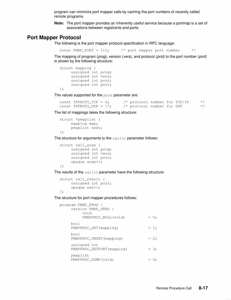
Remote Procedure Call 8-17
program can minimize port mapper calls by caching the port numbers of recently calledremote programs.
Note: The port mapper provides an inherently useful service because a portmap is a set ofassociations between registrants and ports.
Port Mapper ProtocolThe following is the port mapper protocol specification in RPC language:
const PMAP_PORT = 111; /* port mapper port number */
The mapping of program (prog), version (vers), and protocol (prot) to the port number (port)is shown by the following structure:
struct mapping {
unsigned int prog;
unsigned int vers;
unsigned int prot;
unsigned int port;
};
The values supported for the prot parameter are:
const IPPROTO_TCP = 6; /* protocol number for TCP/IP */
const IPPROTO_UDP = 17; /* protocol number for UDP */
The list of mappings takes the following structure:
struct *pmaplist {
mapping map;
pmaplist next;
};
The structure for arguments to the callit parameter follows:
struct call_args {
unsigned int prog;
unsigned int vers;
unsigned int proc;
opaque args<>;
};
The results of the callit parameter have the following structure:
struct call_result {
unsigned int port;
opaque res<>;
};
The structure for port mapper procedures follows:
program PMAP_PROG {
version PMAP_VERS {
void
PMAPPROC_NULL(void) = 0;
bool
PMAPPROC_SET(mapping) = 1;
bool
PMAPPROC_UNSET(mapping) = 2;
unsigned int
PMAPPROC_GETPORT(mapping) = 3;
pmaplist
PMAPPROC_DUMP(void) = 4;

8-18 AIX Communications Programming Concepts
call_result
PMAPPROC_CALLIT(call_args) = 5;
} = 2;
} = 100000;
Port Mapper ProceduresThe port mapper program currently supports two protocols: User Datagram Protocol (UDP)and Transmission Control Protocol/Internet Protocol (TCP/IP). The port mapper is contactedby port number 111 on both protocols.
A description of the port mapper procedures follows.
PMAPPROC_NULL This procedure does no work. By convention, procedure 0 ofany protocol takes no parameters and returns no results.
PMAPPROC_SET When a program first becomes available on a machine, itregisters itself with the port mapper program on that machine.The program passes its program number (prog), versionnumber (vers), transport protocol number (prot), and the port(port) on which it awaits service request. The procedurereturns a Boolean response whose value is either True if theprocedure successfully established the mapping, or False ifotherwise. The procedure does not establish a mapping if thevalues for the prog, vers, and prot parameters indicate amapping already exists.
PMAPPROC_UNSET When a program becomes unavailable, it should unregisteritself with the port mapper program on the same machine. Theparameters and results have meanings identical to those of thePMAPPROC_SET procedure. The protocol and port numberfields of the argument are ignored.
PMAPPROC_GETPORT Given a program number (prog), version number (vers), andtransport protocol number (prot), this procedure returns theport number on which the program is awaiting call requests. Aport value of zero means the program has not been registered.The port parameter of the argument is then ignored.
PMAPPROC_DUMP This procedure enumerates all entries in the port mapperdatabase. The procedure takes no parameters and returns alist of prog, vers, prot, and port values.
PMAPPROC_CALLIT This procedure allows a caller to call another remoteprocedure on the same machine without knowing the remoteprocedure’s port number. It supports broadcasts to arbitraryremote programs through the well–known port mapper port.The prog, vers, and proc parameters, and the bytes of the argsparameter of an RPC call represent the program number,version number, procedure number, and arguments,respectively. The PMAPPROC_CALLIT procedure sends aresponse only if the procedure is successfully run. The portmapper communicates with the remote program using UDPonly. The procedure returns the remote program’s port number,and the bytes of results are the results of the remoteprocedure.

Remote Procedure Call 8-19
Programming in RPC Remote procedure calls can be made from any language. Remote Procedure Call (RPC)protocol is generally used to communicate between processes on different workstations.However, RPC works just as well for communication between different processes on thesame workstation.
The RPC interface can be seen as being divided into three layers: highest, intermediate,and lowest. The highest layer of RPC is totally transparent to the operating system,workstation, and network on which it runs. This level is actually a method for using RPCroutines, rather than a part of RPC proper.
The intermediate layer is RPC proper. At the intermediate layer, the programmer need notconsider details about sockets or other low–level implementation mechanisms. Theprogrammer simply makes remote procedure calls to routines on other workstations.
The lowest layer of RPC allows the programmer greatest control. Programs written at thislevel can be more efficient.
Both intermediate and lower–level RPC programming entail assigning program numbers,version numbers, and procedure numbers. An RPC server can be started from the inetddaemon.
Assigning Program NumbersA central system authority administers the program number (prog parameter). A programnumber permits the implementation of a remote program. The first implementation of aprogram is usually version number 1.
A program number is assigned by groups of 0x20000000 (decimal 536870912), accordingto the following list:
0–1xxxxxxx This group of numbers is predefined and administered by theoperating system. The numbers should be identical for allsystem customers.
20000000–3xxxxxxx The user defines this group of numbers. The numbers are usedfor new applications and for debugging new programs.
40000000–5xxxxxxx This group of numbers is transient and is used for applicationsthat generate program numbers dynamically.
60000000–7xxxxxxx Reserved.
80000000–9xxxxxxx Reserved.
a0000000–bxxxxxxx Reserved.
c0000000–dxxxxxxx Reserved.
e0000000–fxxxxxxxx Reserved.
The first group of numbers is predefined, and should be identical for all customers. If acustomer develops an application that might be of general interest, that application can beregistered by assigning a number in the first range. The second group of numbers isreserved for specific customer applications. This range is intended primarily for debuggingnew programs. The third group is reserved for applications that generate program numbersdynamically. The final groups are reserved for future use and should not be used.
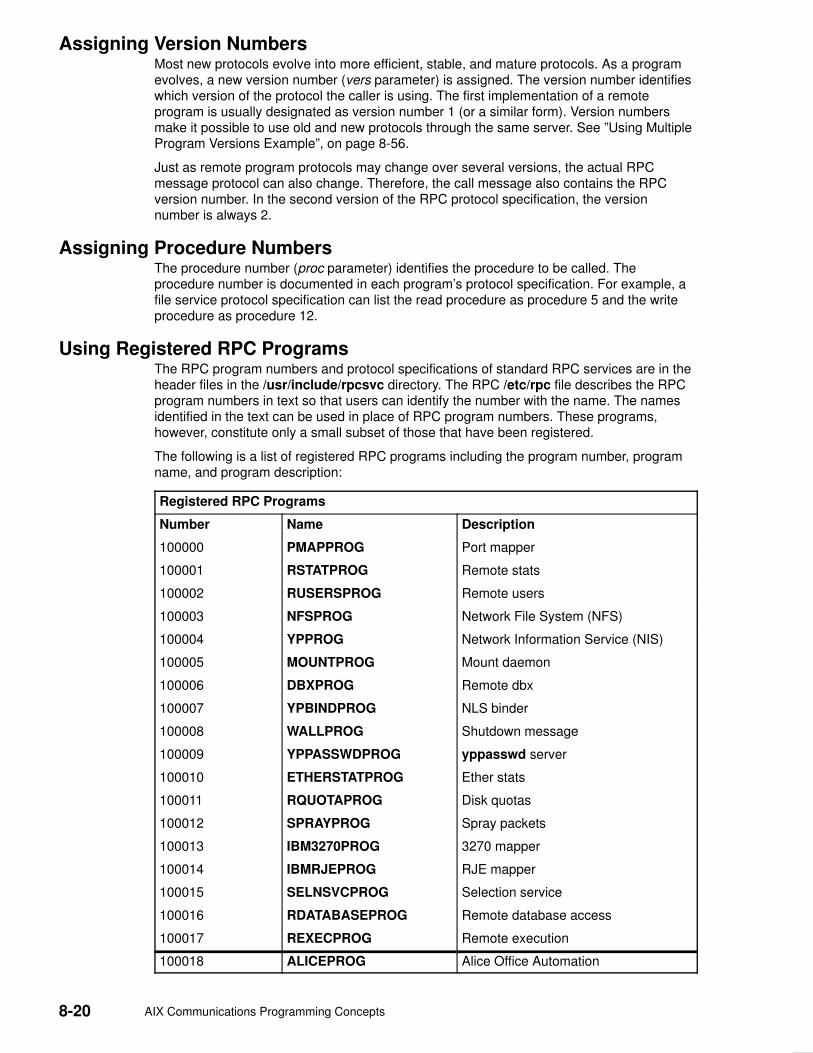
8-20 AIX Communications Programming Concepts
Assigning Version NumbersMost new protocols evolve into more efficient, stable, and mature protocols. As a programevolves, a new version number (vers parameter) is assigned. The version number identifieswhich version of the protocol the caller is using. The first implementation of a remoteprogram is usually designated as version number 1 (or a similar form). Version numbersmake it possible to use old and new protocols through the same server. See ”Using MultipleProgram Versions Example”, on page 8-56.
Just as remote program protocols may change over several versions, the actual RPCmessage protocol can also change. Therefore, the call message also contains the RPCversion number. In the second version of the RPC protocol specification, the versionnumber is always 2.
Assigning Procedure NumbersThe procedure number (proc parameter) identifies the procedure to be called. Theprocedure number is documented in each program’s protocol specification. For example, afile service protocol specification can list the read procedure as procedure 5 and the writeprocedure as procedure 12.
Using Registered RPC ProgramsThe RPC program numbers and protocol specifications of standard RPC services are in theheader files in the /usr/include/rpcsvc directory. The RPC /etc/rpc file describes the RPCprogram numbers in text so that users can identify the number with the name. The namesidentified in the text can be used in place of RPC program numbers. These programs,however, constitute only a small subset of those that have been registered.
The following is a list of registered RPC programs including the program number, programname, and program description:
Registered RPC Programs
Number Name Description
100000 PMAPPROG Port mapper
100001 RSTATPROG Remote stats
100002 RUSERSPROG Remote users
100003 NFSPROG Network File System (NFS)
100004 YPPROG Network Information Service (NIS)
100005 MOUNTPROG Mount daemon
100006 DBXPROG Remote dbx
100007 YPBINDPROG NLS binder
100008 WALLPROG Shutdown message
100009 YPPASSWDPROG yppasswd server
100010 ETHERSTATPROG Ether stats
100011 RQUOTAPROG Disk quotas
100012 SPRAYPROG Spray packets
100013 IBM3270PROG 3270 mapper
100014 IBMRJEPROG RJE mapper
100015 SELNSVCPROG Selection service
100016 RDATABASEPROG Remote database access
100017 REXECPROG Remote execution
100018 ALICEPROG Alice Office Automation

Remote Procedure Call 8-21
100019 SCHEDPROG Scheduling service
100020 LOCKPROG Local lock manager
100021 NETLOCKPROG Network lock manager
100023 STATMON1PROG Status monitor1
100024 STATMON2PROG Status monitor2
100025 SELNLIBPROG Selection library
100026 BOOTPARAMPROG Boot parameters service
100027 MAZEPROG Mazewars games
100028 YPUPDATEPROG YP update
100029 KEYSERVEPROG Key server
100030 SECURECMDPROG Secure login
100031 NETFWDIPROG NFS net forwarder init
100032 NETFWDTPROG NFS net forwarder trans
100033 SUNLINKMAP_PROG Sunlink MAP
100034 NETMONPROG Network monitor
100035 DBASEPROG Lightweight database
100036 PWDAUTHPROG Password authorization
100037 TFSPROG Translucent file service
100038 NSEPROG NSE server
100039 NSE_ACTIVATE_PROG NSE activate daemon
150001 PCNFSDPROGx PC password authorization
200000 PYRAMIDLOCKINGPROG Pyramid–locking
200001 PYRAMIDSYS5 Pyramid–sys5
200002 CADDS_IMAGE CV cadds_image
300001 ADT_RFLOCKPROG ADT file locking
Using the Highest Layer of RPCProgrammers who write remote procedure calls can make the highest layer of RPCavailable to other users through a simple C language front–end routine that entirely hidesthe networking. To illustrate a call at the highest level, a program can simply call thernusers routine, a C routine that returns the number of users on a remote workstation. Theuser need not be explicitly aware of using RPC.
Other RPC service library routines available to the C programmer are:
rusers Returns information about users on a remote workstation.
havedisk Determines whether the remote workstation has a disk.
rstat Gets performance data from a remote kernel.
rwall Writes to a specified remote workstation.
yppasswd Updates a user password in the Network Information Service (NIS).
RPC services, such as the mount and spray commands, are not available to the Cprogrammer as service library routines. Though unavailable, these services have RPCprogram numbers and can be invoked with the callrpc subroutine. Most of these serviceshave compilable rpcgen protocol description files that simplify the process of developingnetwork applications.
For more information, see ”Using the Highest Layer of RPC Example”, on page 8-47.
8-22 AIX Communications Programming Concepts
Using the Intermediate Layer of RPCThe intermediate layer RPC routines are used for most applications. The intermediate layeris sometimes overlooked in programming due to its simplicity and lack of flexibility. At thislevel, RPC does not allow time–out specifications, choice of transport, or process control incase of errors. Nor does the intermediate layer of RPC support multiple types of callauthentication. The programmer often needs these kinds of control.
Remote procedure calls are made with the registerrpc, callrpc, and svc_run systemroutines, which belong to the intermediate layer of RPC. The registerrpc and callrpcroutines are the most fundamental. The registerrpc routine obtains a unique system–wideprocedure identification number. The callrpc routine executes the remote procedure call.
Each RPC procedure is uniquely defined by a program number, version number, andprocedure number. The program number specifies a group of related remote procedures,each of which has a different procedure number. Each program also has a version number.Therefore, when a minor change, such as adding a new procedure, is made to a remoteservice, a new program number need not be assigned.
The RPC interface also handles arbitrary data structures, regardless of the different byteorders or structure layout conventions at various workstations. For more information, seethe ”Using the Intermediate Layer of RPC Example”, on page 8-48.
Using the registerrpc RoutineOnly the User Datagram Protocol (UDP) transport mechanism can use the registerrpcroutine. This routine is always safe in conjunction with calls generated by the callrpcroutine. The UDP transport mechanism can deal only with arguments and results that areless than 8KB in length.
The RPC registerrpc routine includes the following parameters:
• Program number
• Version number
• Procedure number to be called
• Procedure name
• XDR (eXternal Data Representation) subroutine that decodes the procedure parameters
• XDR subroutine that encodes the procedure calls
After registering the local procedure, the server program’s main procedure calls thesvc_run routine, which is the RPC library’s remote procedure dispatcher. The svc_runroutine then calls the remote procedure in response to RPC messages. The dispatcher usesthe XDR data filters that are specified when the remote procedure is registered to handledecoding procedure arguments and encoding results.

Remote Procedure Call 8-23
Using the callrpc RoutineThe RPC callrpc routine executes remote procedure calls. See ”Using the IntermediateLayer of RPC Example”, on page 8-48.
The callrpc routine includes the following parameters:
• Name of the remote server workstation
• Program number
• Version number of the program
• Procedure number
• Input XDR filter primitive
• Argument to be encoded and passed to the remote procedure
• Output XDR filter for decoding the results returned by the remote procedure
• Pointer to the location where the procedure’s results are to be stored
Multiple arguments and results can be embedded in structures. If the callrpc routinecompletes successfully, it returns a value of zero. Otherwise, it returns a nonzero value. Thereturn codes are cast in integer data–type values in the rpc/clnt.h file.
If the callrpc routine gets no answer after several attempts to deliver a message, it returnswith an error code. The delivery mechanism is UDP. Adjusting the number of retries or usinga different protocol requires the use of the lower layer of the RPC library.
Passing Arbitrary Data TypesThe RPC interface can handle arbitrary data structures, regardless of the different byteorders or structure layout conventions on different machines, by converting the structures toa network standard called XDR before sending them over the wire. The process ofconverting from a particular machine representation to XDR format is called serializing, andthe reverse process is called deserializing.
The input and output parameters of the callrpc and registerrpc routines can be a built–inor user–supplied procedure. For more information, see ”Showing How RPC PassesArbitrary Data Types Example”, on page 8-54.
The XDR language has the following built–in subroutines:
• xdr_bool
• xdr_char
• xdr_u_char
• xdr_enum
• xdr_int
• xdr_u_int
• xdr_long
• xdr_u_long
• xdr_short
• xdr_u_short
• xdr_wrapstring
Although the xdr_string subroutine exists, it passes three parameters to its XDR routine.The xdr_string subroutine cannot be used with the callrpc and registerrpc subroutines,which pass only two parameters. However, the xdr_string routine can be called with thexdr_wrapstring routine, which also has only two parameters.

8-24 AIX Communications Programming Concepts
If completion is successful, XDR subroutines return a nonzero value (that is, a True value inthe C language). Otherwise, they return a value of zero (False).
In addition to the built–in primitives are the following prefabricated building blocks:
• xdr_array
• xdr_bytes
• xdr_opaque
• xdr_pointer
• xdr_reference
• xdr_string
• xdr_union
• xdr_vector
Using the Lowest Layer of RPCFor the higher layers, RPC takes care of many details automatically. However, the lowestlayer of the RPC library allows the programmer to change the default values for thesedetails. The lowest layer of RPC requires familiarity with sockets and their system calls. Formore information, see ”Using the Lowest Layer of RPC Example”, on page 8-50 and ”UsingMultiple Program Versions Example”, on page 8-56.
The lowest layer of RPC may be necessary in the following situations:
• The programmer needs to use Transmission Control Protocol/Internet Protocol (TCP/IP).Higher layers use UDP, which restricts RPC calls to 8KB of data. TCP/IP permits calls tosend long streams of data.
• The programmer wants to allocate and free memory while serializing or deserializingmessages with XDR routines. No system call at the higher levels explicitly permits freeingmemory. XDR routines are used for memory allocation as well as for input and output.
• The programmer needs to perform authentication on the client or server side bysupplying credentials or verifying them, respectively.
Allocating Memory with XDRXDR routines not only do input and output, they also do memory allocation. Consider thefollowing XDR routine, xdr_chararr1, which deals with a fixed array of bytes with lengthSIZE.
xdr_chararr1 (xdrsp, chararr)
XDR *xdrsp;
char chararr[];
{
char *p;
int len;
p = chararr;
len = SIZE;
return (xdr_bytes (xdrsp, &p, &len, SIZE));
}
If space has already been allocated in it, chararr can be called from a server. For example:
char chararr [SIZE];
svc_getargs (transp, xdr_chararr1, chararr);

Remote Procedure Call 8-25
If you want XDR to do the allocation, you need to rewrite this routine in the following way:
xdr_chararr2 (xdrsp, chararrp)
XDR *xdrsp;
char **chararrp;
{
int len;
len = SIZE;
return (xdr_bytes (xdrsp, charrarrp, &len, SIZE));
}
Then the RPC call might look like this:
char *arrptr;
arrptr = NULL;
svc_getargs (transp, xdr_chararr2, &arrptr);
/*
*Use the result here
*/
svc_freeargs (transp, xdr_chararr2, &arrptr);
The character array can be freed with the svc_freeargs macro. This operation does notattempt to free any memory in the variable, indicating the variable is null.
Each XDR routine is responsible for serializing, deserializing, and freeing memory. When anXDR routine is called from the callrpc routine, the serializing part is used. When an XDRroutine is called from the svc_getargs routine, the deserializer is used. When an XDRroutine is called from the svc_freeargs routine, the memory deallocator is used.
Starting RPC from the inetd DaemonAn RPC server can be started from the inetd daemon. The only difference between usingthe inetd daemon and the usual code is that the service creation routine is called. Since theinet passes a socket as file descriptor 0, the following form is used:
transp = svcudp_create(0); /* For UDP */
transp = svctcp_create(0,0,0); /* For listener TCP sockets */
transp = svcfd_create(0,0,0); /* For connected TCP sockets */
In addition, the svc_register routine should be called as follows:
svc_register(transp, PROGNUM, VERSNUM, service, 0)
The final flag is 0 since the program is already registered by the inetd daemon. To exit fromthe server process and return control to the inet, the user must explicitly exit. The svc_runroutine never returns.
Entries in the /etc/inetd.conf file for RPC services take one of the following two forms:
p_name sunrpc_udp udp wait user server args version
p_name sunrpc_tcp tcp wait user server args version
where p_name is the symbolic name of the program as it appears in the RPC routine,server is the program implementing the server, and version is the version number of theservice.
If the same program handles multiple versions, then the version number can be a range, asin the following:
rstatd sunrpc_udp udp wait root /usr/sbin/rpc.rstatd rstatd 100001 1–2
Compiling and Linking RPC ProgramsRPC subroutines are part of the libc.a library. Add the following line to the Makefile file:
CFLAGS=–D_BSD –DBSD_INCLUDES

8-26 AIX Communications Programming Concepts
RPC Features The features of Remote Procedure Call (RPC) include batching calls, broadcasting calls,callback procedures, and using the select subroutine. Batching allows a client to send anarbitrarily large sequence of call messages to a server. Broadcasting allows a client to senda data packet to the network and wait for numerous replies. Callback procedures permit aserver to become a client and make an RPC callback to the client’s process. The selectsubroutine examines the I/O descriptor sets whose addresses are passed in the readfds,writefds, and exceptfds parameters to see if some of their descriptors are ready for readingor writing, or have an exceptional condition pending. It then returns the total number ofready descriptors in all the sets.
RPC is also used for the rcp program on Transmission Control Protocol/Internet Protocol(TCP/IP). See ”rcp Process on TCP Example”, on page 8-59.
Batching Remote Procedure CallsBatching allows a client to send an arbitrarily large sequence of call messages to a server.Batching typically uses reliable byte stream protocols, such as TCP/IP, for its transport.When batching, the client never waits for a reply from the server, and the server does notsend replies to batched requests. Normally, a sequence of batch calls should be terminatedby a legitimate, nonbatched RPC to flush the pipeline.
The RPC architecture is designed so that clients send a call message and then wait forservers to reply that the call succeeded. This implies that clients do not compute whileservers are processing a call. However, the client may not want or need anacknowledgment for every message sent. Therefore, clients can use RPC batch facilities tocontinue computing while they wait for a response.
Batching can be thought of as placing RPC messages in a pipeline of calls to a desiredserver. Batching assumes the following:
• Each remote procedure call in the pipeline requires no response from the server, and theserver does not send a response message.
• The pipeline of calls is transported on a reliable byte stream transport such as TCP/IP.
For a client to use batching, the client must perform remote procedure calls on aTCP/IP–based transport. Batched calls must have the following attributes:
• The resulting XDR routine must be 0 (null).
• The remote procedure call’s time out must be 0.
Since the server sends no message, the clients are not notified of any failures that occur.Therefore, clients must handle their own errors.
Since the server does not respond to every call, the client can generate new calls that runparallel to the server’s execution of previous calls. Furthermore, the TCP/IP implementationcan buffer many call messages, and send them to the server with one write subroutine. Thisoverlapped execution decreases the interprocess communication overhead of the client andserver processes as well as the total elapsed time of a series of calls. Batched calls arebuffered, so the client should eventually perform a nonbatched remote procedure call toflush the pipeline with positive acknowledgment.

Remote Procedure Call 8-27
Broadcasting Remote Procedure CallsIn broadcast RPC–based protocols, the client sends a broadcast packet to the network andwaits for numerous replies. Broadcast RPC uses only packet–based protocols, such asUser Datagram Protocol/Internet Protocol (UDP/IP), for its transports. Servers that supportbroadcast protocols respond only when the request is successfully processed and remainsilent when errors occur. Broadcast RPC requires the RPC port mapper service to achieveits semantics. The portmap daemon converts RPC program numbers into Internet protocolport numbers. See ”Broadcasting a Remote Procedure Call Example”, on page 8-57.
The main differences between broadcast RPC and normal RPC are as follows:
• Normal RPC expects only one answer, while broadcast RPC expects one or moreanswers from each responding machine.
• The implementation of broadcast RPC treats unsuccessful responses as garbage byfiltering them out. Therefore, if there is a version mismatch between the broadcaster anda remote service, the user of broadcast RPC may never know.
• All broadcast messages are sent to the port–mapping port. As a result, only services thatregister themselves with their port mapper are accessible through the broadcast RPCmechanism.
• Broadcast requests are limited in size to the maximum transfer unit (MTU) of the localnetwork. For the Ethernet system, the MTU is 1500 bytes.
• Broadcast RPC is supported only by packet–oriented (connectionless) transport protocolssuch as UPD/IP.
RPC Call–back ProceduresOccasionally, the server may need to become a client by making an RPC callback to theclient’s process. To make an RPC callback, the user needs a program number on which tomake the call. The program number is dynamically generated and should be in the transientrange, 0x40000000 to 0x5fffffff. See ”RPC Callback Procedures Example”, on page 8-62 formore information.
Using the select Subroutine on the Server SideThe select subroutine checks the specified file descriptors and message queues to see ifthey are ready for reading (receiving) or writing (sending), or if they have an exceptionalcondition pending. A select procedure allows the server to interrupt an activity, check fordata, and then continue processing the activity. For example, if the server processes RPCrequests while performing another activity that involves periodically updating a datastructure, the process can set an alarm signal to notify the server before calling the svc_runroutine. However, if the current activity is waiting on a file descriptor, the call to the svc_runroutine does not work. See ”Using the select Subroutine Example”, on page 8-58 for moreinformation.
A programmer can bypass the svc_run routine and call the svc_getreqset routine directly.It is necessary to know the file descriptors of the sockets associated with the programsbeing waited on. The programmer can have a select statement that waits on both the RPCsocket and specified descriptors.
Note: The svc_fds parameter is a bit mask of all the file descriptors that RPC is using forservices. It can change each time an RPC library routine is called becausedescriptors are continually opened and closed. TCP/IP connections are an example.

8-28 AIX Communications Programming Concepts
RPC Language The Remote Procedure Call Language (RPCL) is identical to the eXternal DataRepresentation (XDR) language, except for the added program definition.
RPC Language DescriptionsBecause XDR data types are described in a formal language, procedures that operate onthese data types must be described in a formal language. The RPCL, an extension to theXDR language, is used for this purpose.
RPC uses RPCL as the input language for its protocol and routines. RPCL specifies datatypes used by RPC and generates XDR routines that standardize representation of thetypes. To implement service protocols and routines, RPCL uses the rpcgen command tocompile input in corresponding C language code.
RPC language descriptions include:
• Definitions
• Structures
• Unions
• Enumerations
• Typedefs
• Constants
• Programs
• Declarations
See ”RPC Language ping Program Example”, on page 8-66 for more information. Also, see”Exceptions to the RPCL Rules”, on page 8-32 for instances where these rules do not apply.
DefinitionsAn RPCL file consists of a series of definitions in the following format:
definition–list:
definition ”;”
definition ”;” definition–list
RPCL recognizes the following six types of definitions:
definition:
enum–definition
struct–definition
union–definition
typedef–definition
const–definition
program–definition

Remote Procedure Call 8-29
StructuresThe C language structures are usually located in header files in either the /usr/include or/usr/include/sys directory, but they can be located in any directory in the file system. AnXDR structure is declared almost exactly like its C language counterpart; for example:
struct–definition:
”struct” struct–ident ”{”
declaration–list
”}”
declaration–list:
declaration ”;”
declaration ”;” declaration–list
Compare the following XDR structure to a two–dimensional coordinate with the C structurethat it is compiled into in the output header file.
struct coord { struct coord {
int x; ––> int x;
int y; int y;
}; };
typedef struct coord coord;
Here, the output is identical to the input, except for the added typedef at the end of theoutput. As a result, the programmer can use coord instead of struct coord whendeclaring items.
UnionsXDR unions are discriminated unions and look different from C unions. XDR unions aremore analogous to Pascal variant records than to C unions. Following is an XDR uniondefinition:
union–definition:
”union” union–ident ”switch” ”(” declaration ”)” ”{”
case–list
”}”
case–list:
”case” value ”:” declaration ”;”
”default” ”:” declaration ”;”
”case” value ”:” declaration ”;” case–list
Following is an example of a type that might be returned as the result of a read dataoperation. If there is no error, the type returns a block of data; otherwise, it returns nothing.
union read_result switch (int errno) {
case 0
opaque data[1024];
default:
void;
};
The type is compiled into the following structure:
struct read_result {
int errno;
union {
char data[1024];
}read_result_u;
};
typedef struct read_result read_result;
Note: The union component of this output structure is identical to the type, except for thetrailing _u.
8-30 AIX Communications Programming Concepts
EnumerationsXDR enumerations have the same syntax as C enumerations.
enum–definition:
”enum” enum–ident ”{”
enum–value–list
”}”
enum–value–list:
enum–value
enum–value ”,” enum–value–list
enum–value:
enum–value–ident
enum–value–ident ”=” value
Compare the following example of an XDR enumeration with the C enumeration it iscompiled into:
enum colortype { enum colortype {
RED = 0, RED = 0,
GREEN = 1, ––> GREEN = 1,
BLUE = 2 BLUE = 2,
}; };
typedef enum colortype colortype;
Type DefinitionsXDR type definitions (typedefs) have the same syntax as C typedefs:
typedef–definition:
”typedef” declaration
The following example defines an fname_type used for declaring file–name strings with amaximum length of 255 characters:
typedef string fname_type<255>; ––> typedef char *fname_type;
ConstantsXDR constants can be used wherever an integer constant is required. The definition for aconstant is:
const–definition:
”const” const–ident ”=” integer
For example, the following defines a constant DOZEN equal to 12:
const DOZEN = 12; ––> #define DOZEN 12
ProgramsRPC programs are declared using the following syntax:
program–definition:
”program” program–ident ”{”
version–list
”}” ”=” value
version–list:
version ”;”
version ”;” version–list
version:
”version” version–ident ”{”
procedure–list
”}” ”=” value
Remote Procedure Call 8-31
procedure–list:
procedure ”;”
procedure ”;” procedure–list
procedure:
type–ident procedure–ident ”(” type–ident ”)” ”=” value
The time protocol is defined as follows:
/*
* time.x: Get or set the time. Time is represented as number
* of seconds since 0:00, January 1, 1970.
*/
program TIMEPROG {
version TIMEVERS {
unsigned int TIMEGET (void) = 1;
void TIMESET (unsigned) = 2;
} = 1;
} = 44;
This file compiles into the following #define statements in the output header file:
#define TIMEPROG 44
#define TIMEVERS 1
#define TIMEGET 1
#define TIMESET 2
DeclarationsXDR includes four types of declarations: simple declarations, fixed–length arraydeclarations, variable–length array declarations, and pointer declarations. Thesedeclarations have the following forms:
declaration:
simple–declaration
fixed–array–declaration
variable–array–declaration
pointer–declaration
Simple DeclarationsSimple XDR declarations are like simple C declarations, as follows:
simple–declaration:
type–ident variable–ident
An example of a simple declaration is:
colortype color; ––> colortype color;
Fixed–length Array DeclarationsFixed–length array declarations are like C array declarations, as follows:
fixed–array–declaration:
type–ident variable–ident ”[” value ”]”
An example of a fixed–length array declaration is:
colortype palette[8]; ––> colortype palette[8]

8-32 AIX Communications Programming Concepts
Variable–length Array DeclarationsVariable–length array declarations have no explicit syntax in C, so XDR invents its ownsyntax using angle brackets. The maximum size is specified between the angle brackets. Aspecific size can be omitted to indicate that the array may be of any size.
variable–array–declaration:
type–ident variable–ident ”<” value ”>”
type–ident variable–ident ”<” ”>”
An example of a set of variable–length array declarations is:
int heights<12>; /* at most 12 items */
int widths<>; /* any number of items */
Note: The maximum size is specified between the angle brackets. The number, but not theangle brackets, may be omitted to indicate that the array can be of any size.
Since variable–length arrays have no explicit syntax in C, these declarations are actuallycompiled into structure definitions, signified by struct. For example, the heightsdeclaration is compiled into the following structure:
struct {
u_int heights_len; /* # of items in array */
int *heights_val; /* # pointer to array */
} heights;
Pointer DeclarationsPointer declarations are made in XDR exactly as they are in C. The programmer cannotsend pointers over a network, but can use XDR pointers for sending recursive data typessuch as lists and trees. In XDR language, the type is called optional–data, instead ofpointer. Pointer declarations have the following form in XDR language:
pointer–declaration:
type–ident ”*” variable–ident
An example of a pointer declaration is:
listitem *next; ––> listitem *next;
RPCL Syntax Requirements for Program DefinitionThe RPCL has the following syntax requirements:
• The program and version keywords are added and cannot be used as identifiers.
• A version name cannot occur more than once within the scope of a program definition.Nor can a version number occur more than once within the scope of a program definition.
• A procedure name cannot occur more than once within the scope of a version definition.Nor can a procedure number occur more than once within the scope of a versiondefinition.
• Program identifiers are in the same name space as the constant and type identifiers.
• Only unsigned constants can be assigned to program, version, and proceduredefinitions.
Exceptions to the RPCL RulesExceptions to the RPC language rules include Booleans, strings, opaque data, and voids.
BooleansThe C language has no built–in Boolean type. However, the RPC library uses a Booleantype called bool_t, which is either True or False. Objects that are declared as type bool inXDR language are compiled into bool_t in the output header file; for example:
bool married; ––> bool_t married;
Remote Procedure Call 8-33
StringsThe C language has no built–in string type. Instead, it uses the null–terminated char *convention. In XDR language, strings are declared using the string keyword, and thencompiled into char * in the output header file. The maximum size contained in the anglebrackets specifies the maximum number of characters allowed in the strings (not countingthe null character). The maximum size may be left off, indicating a string of arbitrary length.
Compare the following examples:
string name<32>; ––> char *name;
string longname<>; ––> char *longname;
Opaque DataOpaque data is used in RPC and XDR to describe untyped data, which consists ofsequences of arbitrary bytes. Opaque data may be declared either as a fixed–length orvariable–length array, as in the following examples:
opaque diskblock[512]; ––> char diskblock[512];
opaque filedata<1024>; ––> struct {
u_int filedata_len;
char *filedata_val;
} filedata
VoidsIn a void declaration, the variable is not named. The declaration is simply void. Voiddeclarations can occur as the argument or result of a remote procedure in only two places:union definitions and program definitions.

8-34 AIX Communications Programming Concepts
rpcgen Protocol Compiler The rpcgen protocol compiler accepts a remote program interface definition written in theRemote Procedure Call language (RPCL), which is similar to the C language. The rpcgencompiler helps programmers write RPC applications simply and directly. The rpcgencompiler debugs the network interface code, thereby allowing programmers to spend theirtime debugging the main features of their applications.
The rpcgen compiler produces a C language output that includes the following:
• Stub versions of the client and server routines
• Server skeleton
• eXternal Data Representation (XDR) filter routines for parameters and results
• A header file that contains common definitions of constants and macros
Client stubs interface with the RPC library to effectively hide the network from its callers.Server stubs similarly hide the network from server procedures invoked by remote clients.The rpcgen output files can be compiled and linked in the usual way. Using any language,programmers write server procedures and link them with the server skeleton to get anexecutable server program.
When application programs use the rpcgen compiler, there are many details to consider. Ofparticular importance is the writing of XDR routines needed to convert procedure argumentsand results into the network format, and vice versa.
Converting Local Procedures into Remote ProceduresApplications running at a single workstation can be converted to run over the network. Aconverted procedure can be called from anywhere in the network. Generally, it is necessaryto identify the types for all procedure inputs and outputs. A null procedure (procedure 0) isnot necessary because the rpcgen compiler generates it automatically. See ”ConvertingLocal Procedures into Remote Procedures Example”, on page 8-67 for more information.
Generating XDR RoutinesThe rpcgen compiler can be used to generate the XDR routines necessary to convert localdata structures into network format, and vice versa. Some types can be defined using thestruct, union, and enum keywords. However, these keywords should not be used insubsequent declarations of variables of these same types. The rpcgen compiler compilesRPC unions into C structures. It is an error to declare these unions using the unionkeyword. See ”Generating XDR Routines Example”, on page 8-72 for more information.
C PreprocessorThe C language preprocessor is run on all input files before they are compiled, making allpreprocessor directives within a .x file legal. Four symbols can be defined, depending uponwhich output file is generated. The symbols and their uses are:
RPC_HDR Represents header file output.
RPC_XDR Represents XDR routine output.
RPC_SVC Represents server skeleton output.
RPC_CLNT Represents client stub output.
The rpcgen compiler also does some preprocessing. Any line that begins with a % (percentsign) is passed directly into the output file without an interpretation of the line. Use of thepercent feature is not generally recommended, since there is no guarantee that the compilerwill put the output where it is intended.

Remote Procedure Call 8-35
Changing Time OutsWhen using the clnt_create subroutine, RPC sets a default time out of 25 seconds forremote procedure calls. The time–out default can be changed using the clnt_controlsubroutine. The following code fragment illustrates the use of this routine:
struct timeval tv
CLIENT *cl;
cl=clnt_create(”somehost”, SOMEPROG, SOMEVERS, ”tcp”);
if (cl=NULL) {
exit(1);
}
tv.tv_sec=60; /* change timeout to 1 minute */
tv.tv_usec=0;
clnt_control(cl, CLSET_TIMEOUT, &tv);
Handling Broadcast on the Server SideWhen a client calls a procedure through broadcast RPC, the server normally replies only if itcan provide useful information to the client. This prevents flooding the network with uselessreplies.
To prevent the server from replying, a remote procedure can return null as its result. Theserver code generated by the rpcgen compiler detects this and does not send a reply. Forexample, the following procedure replies only if it interprets itself to be a server:
void *
reply_if_nfsserver()
{
char notnull; /* just here so we can use its address */
if {access(”/etc/exports”, F_OK) < 0) {
return (NULL); /* prevent RPC from replying */
}
/*
*return non–null pointer so RPC will send out a reply
*/
return ((void *) ¬null);
}
If a procedure returns type void, the server must return a nonnull pointer in order for RPCto reply.

8-36 AIX Communications Programming Concepts
Other Information Passed to Server ProceduresServer procedures often want more information about a remote procedure call than just itsarguments. For example, getting authentication information is important to procedures thatimplement some level of security. This additional information is supplied to the serverprocedure as a second argument. The following example program that allows only rootusers to print a message on the console, demonstrates the use of the second argument:
int *
printmessage_1(msg, rq)
char **msg;
struct svc_req *rq;
{
static in result; /* Must be static */
FILE *f;
struct authunix_parms *aup;
aup=(struct authunix_parms *)rq–>rq_clntcred;
if (aup–>aup_uid !=0) {
result=0;
return (&result);
}
/*
*Same code as before.
*/
}
\

Remote Procedure Call 8-37
List of RPC Programming References The list includes:
• Subroutines and Macros
• Examples
Subroutines and MacrosThe list of subroutines and macros is arranged by function:
• Authenticating Remote Procedure Calls (RPCs)
• Managing the Client
• Managing the Server
• Using RPC Utilities
• Using Data Encryption Standards (DES) Interface to the keyserv Daemon
• Interfacing to the portmap Daemon
• Describing and Encoding Remote Procedure Calls
Authenticating Remote Procedure CallsRPC provides these subroutines and macros for creating and destroying authenticationinformation:
authnone_create Creates null authentication information.
authunix_create Creates an authentication handle with AIX permissions.
authunix_create_default Sets the authentication to the default.
authdes_create Enables the use of DES from the client side.
authdes_getucred Maps a DES credential into a UNIX credential.
auth_destroy Destroys authentication information.
Managing the ClientRPC provides subroutines and macros for the following client management tasks:
• Creating an RPC client for a remote program
• Changing or retrieving client information
• Destroying a client RPC handle
• Broadcasting a remote procedure call
• Calling a remote procedure
• Freeing memory allocated by RPC and eXternal Data Representation (XDR)
• Handling Client Errors
Creating an RPC Client for a Remote Program
clntraw_create Creates a sample RPC client handle for simulation.
clnttcp_create Creates a Transmission Control Protocol/Internet Protocol (TCP/IP)client transport handle.
clntudp_create Creates a User Datagram Protocol/Internet Protocol (UDP/IP) clienttransport handle.
clnt_create Creates a generic client transport handle.

8-38 AIX Communications Programming Concepts
Changing or Retrieving Client Information
clnt_control Changes or retrieves information about a client object.
Destroying a Client RPC Handle
clnt_destroy Destroys a client’s RPC handle.
Broadcasting a Remote Procedure Call
clnt_broadcast Broadcasts a remote procedure call to all network hosts.
Calling a Remote Procedure
callrpc Calls the remote procedure on the machine associated with the hostparameter.
clnt_call Calls the remote procedure associated with the clnt parameter.
Freeing Memory Allocated by RPC and XDR
clnt_freeres Frees memory allocated by RPC and XDR.
Handling Client Errors
clnt_pcreateerror Identifies why a client RPC handle was not created.
clnt_perrno Specifies the condition of the stat parameter.
clnt_perror Determines why a remote procedure call failed.
clnt_geterr Copies error information from a client transport handle.
clnt_spcreateerror Identifies why a client RPC handle was not created.
clnt_sperrno Specifies the condition of the stat parameter.
clnt_sperror Indicates why a remote procedure call failed.
Managing the ServerRPC provides subroutines and macros for the following server management tasks:
• Creating an RPC service transport handle
• Destroying an RPC service transport handle
• Registering and unregistering RPC procedures and handles
• Handling an RPC request
• Handling server errors
Creating an RPC Service Transport Handle
svcraw_create Creates a sample RPC service handle for simulation.
svctcp_create Creates a TCP/IP service transport handle.
svcudp_create Creates a UDP/IP service transport handle.
svcfd_create Creates a service on any open file descriptor.
Destroying an RPC Service Transport Handle
svc_destroy Destroys a service transport handle.

Remote Procedure Call 8-39
Registering and Unregistering RPC Procedures and Handles
registerrpc Registers a procedure with the RPC service.
xprt_register Registers an RPC service transport handle.
xprt_unregister Removes an RPC service transport handle.
svc_register Maps a remote procedure.
svc_unregister Removes mappings between procedures and objects.
Handling an RPC Request
svc_run Signals a wait for the arrival of RPC requests.
svc_getreqset Services an RPC request.
svc_getargs Decodes the arguments of an RPC request.
svc_sendreply Sends back the results of a remote procedure call.
svc_freeargs Frees data allocated by the RPC and XDR system.
svc_getcaller Gets the network address of the caller of a procedure.
Handling Server Errors
svcerr_auth Indicates that the remote procedure call cannot be completeddue to an authentication error.
svcerr_decode Indicates that the parameters of a request cannot be decoded.
svcerr_noproc Indicates that the remote procedure call cannot be completedbecause the program cannot support the requested procedure.
svcerr_noprog Indicates that the remote procedure call cannot be completedbecause the program is not registered.
svcerr_progvers Indicates that the remote procedure call cannot be completedbecause the program version is not registered.
svcerr_systemerr Indicates that the remote procedure call cannot be completeddue to an error not covered by any protocol.
svcerr_weakauth Indicates that the remote procedure call cannot be completeddue to insufficient authentication security parameters.
Using RPC Utilities
host2netname Converts a host name to a network name.
netname2host Converts a network name to a host name.
netname2user Converts a network name to a user ID.
user2netname Converts a user ID to a network name.
getnetname Installs the network name of the caller in the array.
get_myaddress Gets the user’s IP address.
getrpcent, getrpcbyname, getrpcbynumber, setrpcent, or endrpcent
Accesses the /etc/rpc file.
Accesses the /etc/rpc file.
rtime Returns the remote time in the timeval structure.

8-40 AIX Communications Programming Concepts
Using DES Interface to the keyserv Daemon
key_decryptsession Decrypts a server network name and a DES key.
key_encryptsession Encrypts a server network name and a DES key.
key_gendes Requests a secure conversation key from the keyserv daemon.
key_setsecret Sets the key for the user ID of the calling process.
Interfacing to the portmap Daemon
pmap_getmaps Returns a list of the current RPC port mappings.
pmap_getport Requests the port number on which a service waits.
pmap_rmtcall Instructs the portmap daemon to make an RPC.
pmap_set Maps an RPC to a port.
pmap_unset Destroys the mapping between the RPC and the port.
xdr_pmap Describes parameters for portmap procedures.
xdr_pmaplist Describes a list of port mappings externally.
Describing and Encoding Remote Procedure CallsRPC provides subroutines for describing and encoding RPC call and reply messages,authentication, and port mappings:
xdr_accepted_reply Encodes RPC reply messages.
xdr_authunix_parms Describes UNIX–style credentials.
xdr_callhdr Describes RPC call header messages.
xdr_callmsg Describes RPC call messages.
xdr_opaque_auth Describes RPC authentication messages.
xdr_rejected_reply Describes RPC message rejection replies.
xdr_replymsg Describes RPC message replies.
ExamplesUsing UNIX Authentication Example, on page 8-41.
DES Authentication Example, on page 8-44.
Using the Highest Layer of RPC Example, on page 8-47.
Using the Intermediate Layer of RPC Example, on page 8-48.
Using the Lowest Layer of RPC Example, on page 8-50.
Showing How RPC Passes Arbitrary Data Types Example, on page 8-54.
Using Multiple Program Versions Example, on page 8-56.
Broadcasting a Remote Procedure Call Example, on page 8-57.
Using the select Subroutine Example, on page 8-58.
rcp Process on TCP Example, on page 8-59.
RPC Callback Procedures Example, on page 8-62.
RPC Language ping Program Example, on page 8-66.
Converting Local Procedures into Remote Procedures Example, on page 8-67.
Generating XDR Routines Example, on page 8-72.

Remote Procedure Call 8-41
Using UNIX Authentication Example This example shows how UNIX authentication works on both the client and server sides.
UNIX Authentication on the Client SideTo use UNIX authentication, the programmer first creates the Remote Procedure Call (RPC)client handle and then sets the authentication parameter.
The RPC client handle is created as follows:
clnt = clntudp_create (address, prognum, versnum, wait, sockp)
The UNIX authentication parameter is set as follows:
clnt–>cl_auth = authunix_create_default();
Each remote procedure call associated with the client (clnt) then carries the followingUNIX–style authentication credentials structure:
/*
* UNIX style credentials.
*/
struct authunix_parms {
u_long aup_time; /* credentials creation time */
char *aup_machname; /* host name where client is */
int aup_uid; /* client’s UNIX effective uid */
int aup_gid; /* client’s current group id */
u_int aup_len; /* element length of aup_gids */
int *aup_gids; /* array of groups user is in */
};
The authunix_create_default subroutine sets these fields by invoking the appropriatesubroutines. The UNIX–style authentication is valid until destroyed with the followingroutine:
auth_destroy(clnt–>cl_auth);
UNIX Authentication on the Server SideThis example shows how to use UNIX authorization on the server side.
The following is a structure definition of a request handle passed to a service dispatchroutine at the server:
/*
* An RPC Service request
*/
struct svc_req {
u_long rq_prog; /* service program number */
u_long rq_vers; /* service protocol vers num */
u_long rq_proc; /* desired procedure number */
struct opaque_auth rq_cred; /* raw credentials from wire */
caddr_t rq_clntcred; /* credentials (read only) */
};
Except for the style or flavor of authentication credentials, the rq_cred routine is opaque.
/*
* Authentication info. Mostly opaque to the programmer.
*/
struct opaque_auth {
enum_t oa_flavor; /* style of credentials */
caddr_t oa_base; /* address of more auth stuff */
u_int oa_length; /* not to exceed MAX_AUTH_BYTES */
};

8-42 AIX Communications Programming Concepts
Before passing a request to the service dispatch routine, RPC guarantees:
• The request’s rq_cred field is in an acceptable form. Therefore, the service implementormay inspect the request’s rq_cred.oa_flavor to determine which style of authenticationthe caller used. The service implementor may also wish to inspect the other rq_credfields if the authentication style is not one of the styles supported by the RPC package.
• The request’s rq_clntcred field is either null or points to a well–formed structure thatcorresponds to a supported style of authentication credentials. The rq_clntcred field cancurrently be set as a pointer to an authunix_parms structure for UNIX–styleauthentication. If rq_clntcred is null, the service implementor can inspect the otheropaque fields of the rq_cred credential for any new types of authentication that may beunknown to the RPC package.
The following example uses UNIX authentication on the server side. Here, the remote usersservice example is extended so that it computes results for all users except user ID (UID)16:
nuser(rqstp, transp)
struct svc_req *rqstp;
SVCXPRT *transp;
{
struct authunix_parms *unix_cred;
int uid;
unsigned long nusers;
/*
* we don’t care about authentication for null proc
*/
if (rqstp–>rq_proc == NULLPROC) {
if (!svc_sendreply(transp, xdr_void, 0)) {
fprintf(stderr, ”can’t reply to RPC call\n”);
return (1);
}
return;
}
/*
* now get the uid
*/
switch (rqstp–>rq_cred.oa_flavor) {
case AUTH_UNIX:
unix_cred =
(struct authunix_parms *)rqstp–>rq_clntcred;
uid = unix_cred–>aup_uid;
break;
case AUTH_NULL:
default:
svcerr_weakauth(transp);
return;
}

Remote Procedure Call 8-43
switch (rqstp–>rq_proc) {
case RUSERSPROC_NUM:
/*
* make sure caller is allowed to call this proc
*/
if (uid == 16) {
svcerr_systemerr(transp);
return;
}
/*
* Code here to compute the number of users
* and assign it to the variable nusers
*/
if (!svc_sendreply(transp, xdr_u_long, &nusers)) {
fprintf(stderr, ”can’t reply to RPC call\n”);
return (1);
}
return;
default:
svcerr_noproc(transp);
return;
}
}

8-44 AIX Communications Programming Concepts
DES Authentication Example This example illustrates how Data Encryption Standard (DES) authentication works on boththe client side and the server side.
DES Authentication on the Client SideTo use DES authentication, the client first sets its authentication handle as follows:
cl–>cl_auth =
authdes_create(servername, 60, &server_addr, NULL);
The first argument (servername) to the authdes_create routine is the network name, ornet name, of the owner of the server process. Typically, server processes are rootprocesses. The net name can be derived using the following call:
char servername[MAXNETNAMELEN];
host2netname(servername, rhostname, NULL);
The rhostname parameter is the host name of the machine on which the server process isrunning. The host2netname routine supplies the servername that will contain this netname for the root process. If the server process is run by a regular user, the user2netnameroutine can be called instead.
The following example illustrates a server process with the same user ID as the client:
char servername[MAXNETNAMELEN];
user2netname(servername, getuid(), NULL);
The user2netname and host2netname routines identify the naming domain at the serverlocation. The NULL parameter in this example means that the local domain name should beused.
The second argument (60) to the authdes_create routine identifies the lifetime of thecredential, which is 60 seconds. This means the credential has 60 seconds until expiration.The server Remote Procedure Call (RPC) subsystem does not grant either a secondrequest within the 60–second lifetime or requests made after the credential has expired.
The third argument (&server_addr) to the authdes_create routine is the address of thehost with which to synchronize. DES authentication requires that the server and client agreeon the time. The time is determined by the server when it receives the address. If the serverand client times are already synchronized, the argument can be set to null.
The final argument (NULL) to the authdes_create routine is the address of a DESencryption key that is used to encrypt time stamps and data. Because this argument is null,a random key is chosen. The programmer can get the encryption key from the ah_key fieldof the authentication handle.

Remote Procedure Call 8-45
DES Authentication on the Server SideThe following example illustrates DES authentication on the server side. The server side issimpler than the client side. This example uses AUTH_DES instead of AUTH_UNIX:
#include <sys/time.h>
#include <rpc/auth_des.h>
...
...
nuser(rqstp, transp)
struct svc_req *rqstp;
SVCXPRT *transp;
{
struct authdes_cred *des_cred;
int uid;
int gid;
int gidlen;
int gidlist[10];
/*
* we don’t care about authentication for null proc
*/
if (rqstp–>rq_proc == NULLPROC) {
/* same as before */
}
/*
* now get the uid
*/
switch (rqstp–>rq_cred.oa_flavor) {
case AUTH_DES:
des_cred =
(struct authdes_cred *) rqstp–>rq_clntcred;
if (! netname2user(des_cred–>adc_fullname.name,
&uid, &gid, &gidlen, gidlist))
{
fprintf(stderr, ”unknown user: %s\n”,
des_cred–>adc_fullname.name);
svcerr_systemerr(transp);
return;
}
break;
case AUTH_NULL:
default:
svcerr_weakauth(transp);
return;
}

8-46 AIX Communications Programming Concepts
/*
* The rest is the same as UNIX–style authentication
*/
switch (rqstp–>rq_proc) {
case RUSERSPROC_NUM:
/*
* make sure caller is allowed to call this proc
*/
if (uid == 16) {
svcerr_systemerr(transp);
return;
}
/*
* Code here to compute the number of users
* and assign it to the variable nusers
*/
if (!svc_sendreply(transp, xdr_u_long, &nusers)) {
fprintf(stderr, ”can’t reply to RPC call\n”);
return (1);
}
return;
default:
svcerr_noproc(transp);
return;
}
}
Note: The netname2user routine, which is the inverse of the user2netname routine,converts a network ID to a user ID. The netname2user routine also supplies groupIDs, which are not used in this example but may be useful in other programs.

Remote Procedure Call 8-47
Using the Highest Layer of RPC Example The following example shows how a program calls the Remote Procedure Call (RPC) libraryrnusers routine to determine how many users are logged in to a remote workstation:
#include <stdio.h>
main(argc, argv)
int argc;
char **argv;
{
int num;
if (argc != 2) {
fprintf(stderr, ”usage: rnusers hostname\n”);
exit(1);
}
if ((num = rnusers(argv[1])) < 0) {
fprintf(stderr, ”error: rnusers\n”);
exit(–1);
}
printf(”%d users on %s\n”, num, argv[1]);
exit(0);
}
/* to compile: cc –o rnusers rnusers.c –lrpcsvc */

8-48 AIX Communications Programming Concepts
Using the Intermediate Layer of RPC Example The following example shows a simple interface that makes explicit remote procedure callsusing the callrpc routine at the intermediate layer of Remote Procedure Call (RPC). Theinterface can be used on both the client and server sides.
Intermediate Layer of RPC on the Server SideNormally, the server registers each procedure, and then goes into an infinite loop waiting toservice requests. Since there is only a single procedure to register, the main body of theserver message would look like the following:
#include <stdio.h>
#include <rpc/rpc.h>
#include <utmp.h>
#include <rpcsvc/rusers.h>
char *nuser();
main()
{
registerrpc(RUSERSPROG, RUSERSVERS, RUSERSPROC_NUM,
nuser, xdr_void, xdr_u_long);
svc_run(); /* Never returns */
fprintf(stderr, ”Error: svc_run returned!\n”);
exit(1);
}
The registerrpc routine registers a C procedure as corresponding to a given RPCprocedure number. The first three parameters, RUSERSPROG, RUSERSVERS, andRUSERSPROC_NUM, specify the program, version, and procedure numbers of the remoteprocedure to be registered. The nuser parameter is the name of the local procedure thatimplements the remote procedure, and the xdr_void and xdr_u_long parameters arethe eXternal Data Representation (XDR) filters for the remote procedure’s arguments andresults, respectively.

Remote Procedure Call 8-49
Intermediate Layer of RPC on the Client Side#include <stdio.h>
#include <rpc/rpc.h>
#include <utmp.h>
#include <rpcsvc/rusers.h>
main(argc, argv)
int argc;
char **argv;
{
unsigned long nusers;
int stat;
if (argc != 2) {
fprintf(stderr, ”usage: nusers hostname\n”);
exit(–1);
}
if (stat = callrpc(argv[1],
RUSERSPROG, RUSERSVERS, RUSERSPROC_NUM,
xdr_void, 0, xdr_u_long, &nusers) != 0) {
clnt_perrno(stat);
exit(1);
}
printf(”%d users on %s\n”, nusers, argv[1]);
exit(0);
}
The callrpc subroutine has eight parameters. The first, host, specifies the name of theremote server machine. The next three parameters, prognum, versnum, and procnum,specify the program, version, and procedure numbers. The fifth and sixth parameters,inproc and in, are an XDR filter and an argument to be encoded and passed to theremote procedure. The final two parameters, outproc and out, are a filter for decoding theresults returned by the remote procedure and a pointer to the place where the procedure’sresults are to be stored. Multiple arguments and results are handled by embedding them instructures. If the callrpc subroutine completes successfully, it returns zero. Otherwise, itreturns a nonzero value.
Since data types may be represented differently on different machines, the callrpcsubroutine needs both the type of the RPC argument and a pointer to the argument itself.The return value for the RUSERSPROC_NUM parameter is unsigned long, so the callrpcsubroutine has xdr_u_long as its first return parameter. This parameter specifies that theresult is of the unsigned long type. The second return parameter, &nusers, is a pointer towhere the long result is placed. Since the RUSERSPROC_NUM parameter takes no argument,the argument parameter of the callrpc subroutine is xdr_void.

8-50 AIX Communications Programming Concepts
Using the Lowest Layer of RPC Example The following is an example of the lowest layer of Remote Procedure Call (RPC) on theserver and client side using the nusers program.
The Lowest Layer of RPC from the Server SideThe server for the nusers program in the following example does the same thing as aprogram using the registerrpc subroutine at the highest level of RPC. However, thefollowing is written using the lowest layer of the RPC package:
#include <stdio.h>
#include <rpc/rpc.h>
#include <utmp.h>
#include <rpcsvc/rusers.h>
main()
{
SVCXPRT *transp;
int nuser();
transp = svcudp_create(RPC_ANYSOCK);
if (transp == NULL){
fprintf(stderr, ”can’t create an RPC server\n”);
exit(1);
}
pmap_unset(RUSERSPROG, RUSERSVERS);
if (!svc_register(transp, RUSERSPROG, RUSERSVERS,
nuser, IPPROTO_UDP)) {
fprintf(stderr, ”can’t register RUSER service\n”);
exit(1);
}
svc_run(); /* Never returns */
fprintf(stderr, ”should never reach this point\n”);
}
switch (rqstp–>rq_proc) {
case NULLPROC:
if (!svc_sendreply(transp, xdr_void, 0))
fprintf(stderr, ”can’t reply to RPC call\n”);
return;
case RUSERSPROC_NUM:
/*
* Code here to compute the number of users
* and assign it to the nusers variable
*/
if (!svc_sendreply(transp, xdr_u_long, &nusers))
fprintf(stderr, ”can’t reply to RPC call\n”);
return;
default:
svcerr_noproc(transp);
return;
}
}
First, the server gets a transport handle, which is used for receiving and replying to RPCmessages. The registerrpc routine calls the svcudp_create routine to get a UserDatagram Protocol (UDP) handle. If a more reliable protocol is required, the svctcp_createroutine can be called instead. If the argument to the svcudp_create routine isRPC_ANYSOCK, the RPC library creates a socket on which to receive and reply to remoteprocedure calls. Otherwise, the svcudp_create routine expects its argument to be a validsocket number. If a programmer specifies a socket, it can be bound or unbound. If it is

Remote Procedure Call 8-51
bound to a port by the programmer, the port numbers of the svcudp_create routine and theclnttcp_create routine (the low–level client routine) must match.
If the programmer specifies the RPC_ANYSOCK argument, the RPC library routines opensockets. The svcudp_create and clntudp_create routines cause the RPC library routinesto bind the appropriate socket, if not already bound.
A service may register its port number with the local port mapper service. This is done byspecifying a nonzero protocol number in the svc_register routine. A programmer at theclient machine can discover the server port number by consulting the port mapper at theserver workstation. This is done automatically by specifying a zero port number in theclntudp_create or clnttcp_create routines.
After creating a service transport (SVCXPRT) handle, the next step is to call thepmap_unset routine. If the nusers server crashed earlier, this routine erases any trace ofthe crash before restarting. Specifically, the pmap_unset routine erases the entry forRUSERSPROG from the port mapper’s tables.
Finally, the program number for nusers is associated with the nuser procedure. The finalargument to the svc_register routine is normally the protocol being used, in this caseIPPROTO_UDP. Registration is performed at the program level, rather than the procedurelevel.
The nuser user service routine must call and dispatch the appropriate eXternal DataRepresentation (XDR) routines based on the procedure number. The nuser routine has tworequirements, unlike the registerrpc routine which performs them automatically. The first isthat the NULLPROC procedure (currently 0) return with no results. This is a simple test fordetecting whether a remote program is running. Second, the subroutine checks for invalidprocedure numbers. If one is detected, the svcerr_noproc routine is called to handle theerror.
The user service routine serializes the results and returns them to the RPC caller throughthe svc_sendreply routine. The first parameter of this routine is the SVCXPRT handle, thesecond is the XDR routine that indicates return data type, and the third is a pointer to thedata to be returned.
As an example, a RUSERSPROC_BOOL procedure can be added, which has an nusersargument and returns a value of True or False, depending on whether there are nuserslogged on. The following example shows this addition:
case RUSERSPROC_BOOL: {
int bool;
unsigned nuserquery;
if (!svc_getargs(transp, xdr_u_int, &nuserquery) {
svcerr_decode(transp);
return;
}
/*
* Code to set nusers = number of users
*/
if (nuserquery == nusers)
bool = TRUE;
else
bool = FALSE;
if (!svc_sendreply(transp, xdr_bool, &bool)) {
fprintf(stderr, ”can’t reply to RPC call\n”);
return (1);
}
return;
}
The svc_getargs routine takes the following arguments: an SVCXPRT handle, the XDRroutine, and a pointer that indicates where to place the input.

8-52 AIX Communications Programming Concepts
The Lowest Layer of RPC from the Client SideA programmer using the callrpc routine has control over neither the RPC deliverymechanism nor the socket used to transport the data. However, the lowest layer of RPCallows the user to adjust these parameters. The following code can be used to request thenusers service:
#include <stdio.h>
#include <rpc/rpc.h>
#include <utmp.h>
#include <rpcsvc/rusers.h>
#include <sys/socket.h>
#include <sys/time.h>
#include <netdb.h>
main(argc, argv)
int argc;
char **argv;
{
struct hostent *hp;
struct timeval pertry_timeout, total_timeout;
struct sockaddr_in server_addr;
int sock = RPC_ANYSOCK;
register CLIENT *client;
enum clnt_stat clnt_stat;
unsigned long nusers;
if (argc != 2) {
fprintf(stderr, ”usage: nusers hostname\n”);
exit(–1);
}
if ((hp = gethostbyname(argv[1])) == NULL) {
fprintf(stderr, ”can’t get addr for %s\n”,argv[1]);
exit(–1);
}
pertry_timeout.tv_sec = 3;
pertry_timeout.tv_usec = 0;
bcopy(hp–>h_addr, (caddr_t)&server_addr.sin_addr,
hp–>h_length);
server_addr.sin_family = AF_INET;
server_addr.sin_port = 0;
if ((client = clntudp_create(&server_addr, RUSERSPROG,
RUSERSVERS, pertry_timeout, &sock)) == NULL) {
clnt_pcreateerror(”clntudp_create”);
exit(–1);
}
total_timeout.tv_sec = 20;
total_timeout.tv_usec = 0;
clnt_stat = clnt_call(client, RUSERSPROC_NUM, xdr_void,
0, xdr_u_long, &nusers, total_timeout);
if (clnt_stat != RPC_SUCCESS) {
clnt_perror(client, ”rpc”);
exit(–1);
}
clnt_destroy(client);
close(sock);
exit(0);
}
The low–level version of the callrpc routine is the clnt_call macro, which takes a CLIENTpointer rather than a host name. The parameters to the clnt_call macro are a CLIENTpointer, the procedure number, the XDR routine for serializing the argument, a pointer to theargument, the XDR routine for deserializing the return value, a pointer to where the returnvalue is to be placed, and the total time in seconds to wait for a reply. Thus, the number oftries is the time out divided by the clntudp_create time out.
Remote Procedure Call 8-53
The CLIENT pointer is encoded with the transport mechanism. The callrpc routine usesUDP, thus it calls the clntudp_create routine to get a CLIENT pointer. To get TransmissionControl Protocol (TCP), the programmer can call the clnttcp_create routine.
The parameters to the clntudp_create routine are the server address, the program number,the version number, a time–out value (between tries), and a pointer to a socket.
The clnt_destroy call always deallocates the space associated with the client handle. If theRPC library opened the socket associated with the client handle, the clnt_destroy macrocloses it. If the socket was opened by the programmer, it stays open. In cases where thereare multiple client handles using the same socket, it is possible to destroy one handlewithout closing the socket that other handles are using.
The stream connection is made when the call to the clntudp_create macro is replaced by acall to the clnttcp_create routine.
clnttcp_create(&server_addr, prognum, versnum, &sock,
inputsize, outputsize);
In this example, no time–out argument exists. Instead, the send and receive buffer sizesmust be specified. When the clnttcp_create call is made, a TCP connection is established.All remote procedure calls using the client handle use the TCP connection. The server sideof a remote procedure call using TCP is similar, except that the svcudp_create routine isreplaced by the svctcp_create routine, as follows:
transp = svctcp_create(RPC_ANYSOCK, 0, 0);
The last two arguments to the svctcp_create routine are send and receive sizes,respectively. If 0 is specified for either of these, the system chooses a reasonable default.
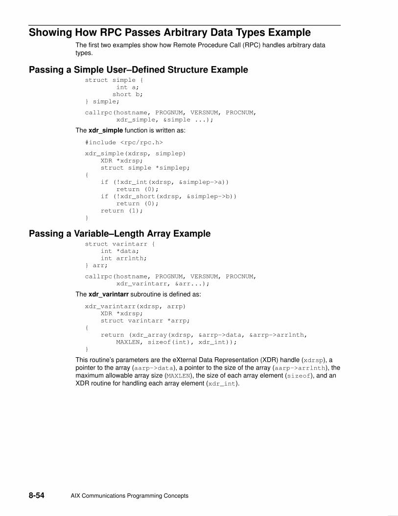
8-54 AIX Communications Programming Concepts
Showing How RPC Passes Arbitrary Data Types Example The first two examples show how Remote Procedure Call (RPC) handles arbitrary datatypes.
Passing a Simple User–Defined Structure Examplestruct simple {
int a;
short b;
} simple;
callrpc(hostname, PROGNUM, VERSNUM, PROCNUM,
xdr_simple, &simple ...);
The xdr_simple function is written as:
#include <rpc/rpc.h>
xdr_simple(xdrsp, simplep)
XDR *xdrsp;
struct simple *simplep;
{
if (!xdr_int(xdrsp, &simplep–>a))
return (0);
if (!xdr_short(xdrsp, &simplep–>b))
return (0);
return (1);
}
Passing a Variable–Length Array Examplestruct varintarr {
int *data;
int arrlnth;
} arr;
callrpc(hostname, PROGNUM, VERSNUM, PROCNUM,
xdr_varintarr, &arr...);
The xdr_varintarr subroutine is defined as:
xdr_varintarr(xdrsp, arrp)
XDR *xdrsp;
struct varintarr *arrp;
{
return (xdr_array(xdrsp, &arrp–>data, &arrp–>arrlnth,
MAXLEN, sizeof(int), xdr_int));
}
This routine’s parameters are the eXternal Data Representation (XDR) handle (xdrsp), apointer to the array (aarp–>data), a pointer to the size of the array (aarp–>arrlnth), themaximum allowable array size (MAXLEN), the size of each array element (sizeof), and anXDR routine for handling each array element (xdr_int).

Remote Procedure Call 8-55
Passing a Fixed–Length Array ExampleIf the size of the array is known in advance, the programmer can call the xdr_vectorsubroutine to serialize fixed–length arrays, as in the following example:
int intarr[SIZE];
xdr_intarr(xdrsp, intarr)
XDR *xdrsp;
int intarr[];
{
int i;
return (xdr_vector(xdrsp, intarr, SIZE, sizeof(int),
xdr_int));
}
Passing Structure with Pointers ExampleThe following example calls the previously written xdr_simple routine as well as the built–inxdr_string and xdr_reference functions. The xdr_reference routine chases pointers.
struct finalexample {
char *string;
struct simple *simplep;
} finalexample;
xdr_finalexample(xdrsp, finalp)
XDR *xdrsp;
struct finalexample *finalp;
{
if (!xdr_string(xdrsp, &finalp–>string, MAXSTRLEN))
return (0);
if (!xdr_reference(xdrsp, &finalp–>simplep,
sizeof(struct simple), xdr_simple);
return (0);
return (1);
}

8-56 AIX Communications Programming Concepts
Using Multiple Program Versions Example By convention, the first version number of the PROG program is referred to asPROGVERS_ORIG, and the most recent version is PROGVERS. For example, theprogrammer can create a new version of the user program that returns an unsigned shortvalue rather than a long value. If the programmer names this version RUSERSVERS_SHORT,then the following program permits the server to support both programs:
if (!svc_register(transp, RUSERSPROG, RUSERSVERS_ORIG,
nuser, IPPROTO_TCP)) {
fprintf(stderr, ”can’t register RUSER service\n”);
exit(1);
}
if (!svc_register(transp, RUSERSPROG, RUSERSVERS_SHORT,
nuser, IPPROTO_TCP)) {
fprintf(stderr, ”can’t register RUSER service\n”);
exit(1);
}
Both versions can be handled by the same C procedure, as in the following example usingthe nusers procedure:
nuser(rqstp, transp)
struct svc_req *rqstp;
SVCXPRT *transp;
{
unsigned long nusers;
unsigned short nusers2;
switch (rqstp–>rq_proc) {
case NULLPROC:
if (!svc_sendreply(transp, xdr_void, 0)) {
fprintf(stderr, ”can’t reply to RPC call\n”);
return (1);
}
return;
case RUSERSPROC_NUM:
/*
* Code here to compute the number of users
* and assign it to the variable nusers
*/
nusers2 = nusers;
switch (rqstp–>rq_vers) {
case RUSERSVERS_ORIG:
if (!svc_sendreply(transp, xdr_u_long,
&nusers)) {
fprintf(stderr,”can’t reply to RPC call\n”);
}
break;
case RUSERSVERS_SHORT:
if (!svc_sendreply(transp, xdr_u_short,
&nusers2)) {
fprintf(stderr,”can’t reply to RPC call\n”);
}
break;
}
default:
svcerr_noproc(transp);
return;
}
}

Remote Procedure Call 8-57
Broadcasting a Remote Procedure Call Example The following example illustrates broadcast Remote Procedure Call (RPC):
#include <rpc/pmap_clnt.h>
...
enum clnt_stat clnt_stat;
...
clnt_stat = clnt_broadcast(prognum, versnum, procnum,
inproc, in, outproc, out, eachresult)
u_long prognum; /* program number */
u_long versnum; /* version number */
u_long procnum; /* procedure number */
xdrproc_t inpro /* xdr routine for args */
caddr_t in; /* pointer to args */
xdrproc_t outproc /* xdr routine for results */
caddr_t out; /* pointer to results */
bool_t (*eachresult)();/* call with each result gotten */
The eachresult procedure is called each time a result is obtained. This procedure returns aBoolean value that indicates whether the caller wants more responses.
bool_t done;
...
done = eachresult(resultsp, raddr)
caddr_t resultsp;
struct sockaddr_in *raddr; /* Addr of responding machine */
If the done parameter returns a value of True, then broadcasting stops and theclnt_broadcast routine returns successfully. Otherwise, the routine waits for anotherresponse. The request is rebroadcast after a few seconds of waiting. If no response comesback, the routine returns with a value of RPC_TIMEDOUT.

8-58 AIX Communications Programming Concepts
Using the select Subroutine Example The code for the svc_run routine with the select subroutine is as follows:
void
svc_run()
{
fd_set readfds;
int dtbsz = getdtablesize();
for (;;) {
readfds = svc_fds;
switch (select(dtbsz, &readfds, NULL,NULL,NULL)) {
case –1:
if (errno == EINTR)
continue;
perror(”select”);
return;
case 0:
break;
default:
svc_getreqset(&readfds);
}
}
}

Remote Procedure Call 8-59
rcp Process on TCP Example The following is an example using the rcp process. This example includes an eXternal DataRepresentation (XDR) procedure that behaves differently on serialization than ondeserialization. The initiator of the Remote Procedure Call (RPC) snd call takes its standardinput and sends it to the rcv process on the server, which prints the data to standard output.The snd call uses Transmission Control Protocol (TCP).
The routine follows:
/*
* The xdr routine:
* on decode, read from wire, write onto fp
* on encode, read from fp, write onto wire
*/
#include <stdio.h>
#include <rpc/rpc.h>
xdr_rcp(xdrs, fp)
XDR *xdrs;
FILE *fp;
{
unsigned long size;
char buf[BUFSIZ], *p;
if (xdrs–>x_op == XDR_FREE) /* nothing to free */
return 1;
while (1) {
if (xdrs–>x_op == XDR_ENCODE) {
if ((size = fread(buf, sizeof(char), BUFSIZ,
fp)) == 0 && ferror(fp)) {
fprintf(stderr, ”can’t fread\n”);
return (1);
}
}
p = buf;
if (!xdr_bytes(xdrs, &p, &size, BUFSIZ))
return 0;
if (size == 0)
return 1;
if (xdrs–>x_op == XDR_DECODE) {
if (fwrite(buf, sizeof(char),size,fp) != size) {
fprintf(stderr, ”can’t fwrite\n”);
return (1);
}
}
}
}
/*
* The sender routines
*/
#include <stdio.h>
#include <netdb.h>
#include <rpc/rpc.h>
#include <sys/socket.h>
#include <sys/time.h>
main(argc, argv)
int argc;
char **argv;

8-60 AIX Communications Programming Concepts
{
int xdr_rcp();
int err;
if (argc < 2) {
fprintf(stderr, ”usage: %s servername\n”, argv[0]);
exit(–1);
}
if ((err = callrpctcp(argv[1], RCPPROG, RCPPROC,
RCPVERS, xdr_rcp, stdin, xdr_void, 0) != 0)) {
clnt_perrno(err);
fprintf(stderr, ”can’t make RPC call\n”);
exit(1);
}
exit(0);
}
callrpctcp(host, prognum, procnum, versnum, inproc, in,
outproc, out)
char *host, *in, *out;
xdrproc_t inproc, outproc;
{
struct sockaddr_in server_addr;
int socket = RPC_ANYSOCK;
enum clnt_stat clnt_stat;
struct hostent *hp;
register CLIENT *client;
struct timeval total_timeout;
if ((hp = gethostbyname(host)) == NULL) {
fprintf(stderr, ”can’t get addr for ’%s’\n”, host);
return (–1);
}
bcopy(hp–>h_addr, (caddr_t)&server_addr.sin_addr,
hp–>h_length);
server_addr.sin_family = AF_INET;
server_addr.sin_port = 0;
if ((client = clnttcp_create(&server_addr, prognum,
versnum, &socket, BUFSIZ, BUFSIZ)) == NULL) {
perror(”rpctcp_create”);
return (–1);
}
total_timeout.tv_sec = 20;
total_timeout.tv_usec = 0;
clnt_stat = clnt_call(client, procnum,
inproc, in, outproc, out, total_timeout);
clnt_destroy(client);
return (int)clnt_stat;
}
/*
* The receiving routines
*/
#include <stdio.h>
#include <rpc/rpc.h>
main()
{
register SVCXPRT *transp;
int rcp_service(), xdr_rcp();

Remote Procedure Call 8-61
if ((transp = svctcp_create(RPC_ANYSOCK,
BUFSIZ, BUFSIZ)) == NULL) {
fprintf(”svctcp_create: error\n”);
exit(1);
}
pmap_unset(RCPPROG, RCPVERS);
if (!svc_register(transp,
RCPPROG, RCPVERS, rcp_service, IPPROTO_TCP)) {
fprintf(stderr, ”svc_register: error\n”);
exit(1);
}
svc_run(); /* never returns */
fprintf(stderr, ”svc_run should never return\n”);
}
rcp_service(rqstp, transp)
register struct svc_req *rqstp;
register SVCXPRT *transp;
{
switch (rqstp–>rq_proc) {
case NULLPROC:
if (svc_sendreply(transp, xdr_void, 0) == 0) {
fprintf(stderr, ”err: rcp_service”);
return (1);
}
return;
case RCPPROC_FP:
if (!svc_getargs(transp, xdr_rcp, stdout)) {
svcerr_decode(transp);
return;
}
if (!svc_sendreply(transp, xdr_void, 0)) {
fprintf(stderr, ”can’t reply\n”);
return;
}
return (0);
default:
svcerr_noproc(transp);
return;
}
}
8-62 AIX Communications Programming Concepts
RPC Callback Procedures Example Occasionally, it is useful to have a server become a client and make a Remote ProcedureCall (RPC) back to the process client. For example, with remote debugging, the client is awindow system program and the server is a debugger running on the remote machine.Usually, the user clicks a mouse button at the debugging window. This step invokes adebugger command that makes a remote procedure call to the server (where the debuggeris actually running), telling it to execute that command. When the debugger hits abreakpoint, however, the roles are reversed. The debugger then makes a remote procedurecall to the window program to inform the user that a breakpoint has been reached.
An RPC callback requires a program number to make the remote procedure call on. Sincethis will be a dynamically generated program number, it should be in the transient range,0x40000000 to 0x5fffffff. The gettransient routine returns a valid program number in thetransient range, and registers it with the port mapper. This routine only talks to the portmapper running on the same machine as the gettransient routine itself. The call to thepmap_set routine is a test–and–set operation. That is, it indivisibly tests whether a programnumber has already been registered, and reserves the number if it has not. On return, thesockp argument contains a socket that can be used as the argument to an svcudp_createor svctcp_create routine.

Remote Procedure Call 8-63
#include <stdio.h>
#include <rpc/rpc.h>
#include <sys/socket.h>
gettransient(proto, vers, sockp)
int proto, vers, *sockp;
{
static int prognum = 0x40000000;
int s, len, socktype;
struct sockaddr_in addr;
switch(proto) {
case IPPROTO_UDP:
socktype = SOCK_DGRAM;
break;
case IPPROTO_TCP:
socktype = SOCK_STREAM;
break;
default:
fprintf(stderr, ”unknown protocol type\n”);
return 0;
}
if (*sockp == RPC_ANYSOCK) {
if ((s = socket(AF_INET, socktype, 0)) < 0) {
perror(”socket”);
return (0);
}
*sockp = s;
}
else
s = *sockp;
addr.sin_addr.s_addr = 0;
addr.sin_family = AF_INET;
addr.sin_port = 0;
len = sizeof(addr);
/*
* may be already bound, so don’t check for error
*/
bind(s, &addr, len);
if (getsockname(s, &addr, &len)< 0) {
perror(”getsockname”);
return (0);
}
while (!pmap_set(prognum++, vers, proto,
ntohs(addr.sin_port))) continue;
return (prognum–1);
}
Note: The call to the ntohs subroutine ensures that the port number in addr.sin_port,which is in network byte order, is passed in host byte order. The pmap_setsubroutine expects host byte order.

8-64 AIX Communications Programming Concepts
The following programs illustrate how to use the gettransient routine. The client makes aremote procedure call to the server, passing it a transient program number. Then the clientwaits around to receive a callback from the server at that program number. The serverregisters the EXAMPLEPROG program so that it can receive the remote procedure callinforming it of the callback program number. Then, at some randomly selected time (onreceiving a SIGALRM signal in this example), the server sends a callback remote procedurecall, using the program number it received earlier.
/*
* client
*/
#include <stdio.h>
#include <rpc/rpc.h>
int callback();
char hostname[256];
main()
{
int x, ans, s;
SVCXPRT *xprt;
gethostname(hostname, sizeof(hostname));
s = RPC_ANYSOCK;
x = gettransient(IPPROTO_UDP, 1, &s);
fprintf(stderr, ”client gets prognum %d\n”, x);
if ((xprt = svcudp_create(s)) == NULL) {
fprintf(stderr, ”rpc_server: svcudp_create\n”);
exit(1);
}
/* protocol is 0 – gettransient does registering
*/
(void)svc_register(xprt, x, 1, callback, 0);
ans = callrpc(hostname, EXAMPLEPROG, EXAMPLEVERS,
EXAMPLEPROC_CALLBACK, xdr_int, &x, xdr_void, 0);
if ((enum clnt_stat) ans != RPC_SUCCESS) {
fprintf(stderr, ”call: ”);
clnt_perrno(ans);
fprintf(stderr, ”\n”);
}
svc_run();
fprintf(stderr, ”Error: svc_run shouldn’t return\n”);
}
callback(rqstp, transp)
register struct svc_req *rqstp;
register SVCXPRT *transp;
{
switch (rqstp–>rq_proc) {
case 0:
if (!svc_sendreply(transp, xdr_void, 0)) {
fprintf(stderr, ”err: exampleprog\n”);
return (1);
}
return (0);
case 1:
if (!svc_getargs(transp, xdr_void, 0)) {
svcerr_decode(transp);
return (1);
}
fprintf(stderr, ”client got callback\n”);
if (!svc_sendreply(transp, xdr_void, 0)) {
fprintf(stderr, ”err: exampleprog”);
return (1);

Remote Procedure Call 8-65
}
}
/*
* server
*/
#include <stdio.h>
#include <rpc/rpc.h>
#include <sys/signal.h>
char *getnewprog();
char hostname[256];
int docallback();
int pnum; /* program number for callback routine */
main()
{
gethostname(hostname, sizeof(hostname));
registerrpc(EXAMPLEPROG, EXAMPLEVERS,
EXAMPLEPROC_CALLBACK, getnewprog, xdr_int, xdr_void);
fprintf(stderr, ”server going into svc_run\n”);
signal(SIGALRM, docallback);
alarm(10);
svc_run();
fprintf(stderr, ”Error: svc_run shouldn’t return\n”);
}
char *
getnewprog(pnump)
char *pnump;
{
pnum = *(int *)pnump;
return NULL;
}
docallback()
{
int ans;
ans = callrpc(hostname, pnum, 1, 1, xdr_void, 0,
xdr_void, 0);
if (ans != 0) {
fprintf(stderr, ”server: ”);
clnt_perrno(ans);
fprintf(stderr, ”\n”);
}
}

8-66 AIX Communications Programming Concepts
RPC Language ping Program Example The following is an example of the specification of a simple ping program described in theRemote Procedure Call language (RPCL):
/*
* Simple ping program
*/
program PING_PROG {
/* Latest and greatest version */
version PING_VERS_PINGBACK {
void
PINGPROC_NULL(void) = 0;
/*
* Ping the caller, return the round–trip time
* (in microseconds). Returns –1 if the operation
* timed out.
*/
int
PINGPROC_PINGBACK(void) = 1;
} = 2;
/*
* Original version
*/
version PING_VERS_ORIG {
void
PINGPROC_NULL(void) = 0;
} = 1;
} = 1;
const PING_VERS = 2; /* latest version */
In this example, the first part of the ping program, PING_VERS_PINGBACK, consists of twoprocedures: PINGPROC_NULL and PINGPROC_PINGBACK. The PINGPROC_NULLprocedure takes no arguments and returns no results. However, it is useful for computinground–trip times from the client to the server. By convention, procedure 0 of an RPCprotocol should have the same semantics and require no kind of authentication. The secondprocedure, PINGPROC_PINGBACK, requests a reverse ping operation from the server. Itreturns the amount of time in microseconds that the operation used.
The second part, or original version of the ping program, PING_VERS_ORIG, does notcontain the PINGPROC_PINGBACK procedure. The original version is useful for compatibilitywith older client programs. When the new ping program matures, this older version may bedropped from the protocol entirely.
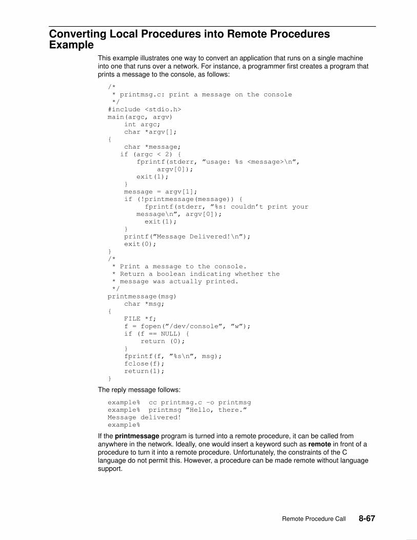
Remote Procedure Call 8-67
Converting Local Procedures into Remote ProceduresExample
This example illustrates one way to convert an application that runs on a single machineinto one that runs over a network. For instance, a programmer first creates a program thatprints a message to the console, as follows:
/*
* printmsg.c: print a message on the console
*/
#include <stdio.h>
main(argc, argv)
int argc;
char *argv[];
{
char *message;
if (argc < 2) {
fprintf(stderr, ”usage: %s <message>\n”,
argv[0]);
exit(1);
}
message = argv[1];
if (!printmessage(message)) {
fprintf(stderr, ”%s: couldn’t print your
message\n”, argv[0]);
exit(1);
}
printf(”Message Delivered!\n”);
exit(0);
}
/*
* Print a message to the console.
* Return a boolean indicating whether the
* message was actually printed.
*/
printmessage(msg)
char *msg;
{
FILE *f;
f = fopen(”/dev/console”, ”w”);
if (f == NULL) {
return (0);
}
fprintf(f, ”%s\n”, msg);
fclose(f);
return(1);
}
The reply message follows:
example% cc printmsg.c –o printmsg
example% printmsg ”Hello, there.”
Message delivered!
example%
If the printmessage program is turned into a remote procedure, it can be called fromanywhere in the network. Ideally, one would insert a keyword such as remote in front of aprocedure to turn it into a remote procedure. Unfortunately, the constraints of the Clanguage do not permit this. However, a procedure can be made remote without languagesupport.

8-68 AIX Communications Programming Concepts
To do this, the programmer must know the data types of all procedure inputs and outputs. Inthis case, the printmessage procedure takes a string as input and returns an integer asoutput. Knowing this, the programmer can write a protocol specification in RemoteProcedure Call language (RPCL) that describes the remote version of PRINTMESSAGE, asfollows:
/*
* msg.x: Remote message printing protocol
*/
program MESSAGEPROG {
version MESSAGEVERS {
int PRINTMESSAGE(string) = 1;
} = 1;
} = 99;
Remote procedures are part of remote programs, so the above protocol declares a remoteprogram containing the single procedure PRINTMESSAGE. This procedure was declared tobe in version 1 of the remote program. No null procedure (procedure 0) is necessary,because the rpcgen command generates it automatically.
Conventionally, all declarations are written with capital letters.
The argument type is string and not char * because a char * in C is ambiguous.Programmers usually intend it to mean a null–terminated string of characters, but it couldalso represent a pointer to a single character or a pointer to an array of characters. InRPCL, a null–terminated string is unambiguously called a string.
Next, the programmer writes the remote procedure itself. The definition of a remoteprocedure to implement the PRINTMESSAGE procedure declared previously can be writtenas follows:
/*
* msg_proc.c: implementation of the remote
*procedure ”printmessage”
*/
#include <stdio.h>
#include <rpc/rpc.h> /* always needed */
#include ”msg.h” /* msg.h will be generated by rpcgen */
/*
* Remote version of ”printmessage”
*/ int *
printmessage_1(msg)
char **msg;
{
static int result; /* must be static! */
FILE *f;
f = fopen(”/dev/console”, ”w”);
if (f == NULL) {
result = 0;
return (&result);
}
fprintf(f, ”%s\en”, *msg);
fclose(f);
result = 1;
return (&result);
}

Remote Procedure Call 8-69
The declaration of the remote procedure printmessage_1 in this step differs from that ofthe local procedure printmessage in the first step, in three ways:
• It takes a pointer to a string instead of the string itself. This is true of all remoteprocedures, which always take pointers to their arguments rather than the argumentsthemselves.
• It returns a pointer to an integer instead of the integer itself. This is also true of remoteprocedures, which generally return a pointer to their results.
• It has a _1 appended to its name. Remote procedures called by the rpcgen commandare named by the following rule: the name in the program definition (herePRINTMESSAGE) is converted to all lowercase letters, and an _ (underscore) and theversion number are appended.
Finally, the programmers declare the main client program that will call the remote procedure,as follows:
/*
* rprintmsg.c: remote version of ”printmsg.c”
*/
#include <stdio.h>
#include <rpc/rpc.h> /* always needed */
#include ”msg.h” /* msg.h will be generated by rpcgen */
main(argc, argv)
int argc;
char *argv[];
{
CLIENT *cl;
int *result;
char *server;
char *message;
if (argc < 3) {
fprintf(stderr,
”usage: %s host message\en”, argv[0]);
exit(1);
}

8-70 AIX Communications Programming Concepts
/*
* Save values of command line arguments
*/
server = argv[1];
message = argv[2];
/*
* Create client ”handle” used for calling MESSAGEPROG on
* the server designated on the command line. We tell
* the RPC package to use the ”tcp” protocol when
* contacting the server.
*/
cl = clnt_create(server, MESSAGEPROG, MESSAGEVERS, ”tcp”);
if (cl == NULL) {
/*
* Couldn’t establish connection with server.
* Print error message and die.
*/
clnt_pcreateerror(server);
exit(1);
}
/*
* Call the remote procedure ”printmessage” on the server
*/
result = printmessage_1(&message, cl);
if (result == NULL) {
/*
* An error occurred while calling the server.
* Print error message and die.
*/
clnt_perror(cl, server);
exit(1);
}
/*
* Okay, we successfully called the remote procedure.
*/
if (*result == 0) {
/*
* Server was unable to print our message.
* Print error message and die.
*/
fprintf(stderr, ”%s: %s couldn’t print your message\n”,
argv[0], server);
exit(1);
}
/*
* The message got printed on the server’s console
*/
printf(”Message delivered to %s!\n”, server);
exit(0);
}
Notes:
1. First a client handle is created using the Remote Procedure Call (RPC) libraryclnt_create routine. This client handle is passed to the stub routines that call the remoteprocedure.
2. The remote procedure printmessage_1 is called exactly the same way as it isdeclared in the msg_proc.c program, except for the inserted client handle as the firstargument.

Remote Procedure Call 8-71
The client program rprintmsg and the server program msg_server are compiled asfollows:
example% rpcgen msg.x
example% cc rprintmsg.c msg_clnt.c –o rprintmsg
example% cc msg_proc.c msg_svc.c –o msg_server
Before compilation, however, the rpcgen protocol compiler is used to perform the followingoperations on the msg.x input file:
• It creates a header file called msg.h that contains #define statements for MESSAGEPROG,MESSAGEVERS, and PRINTMESSAGE for use in the other modules.
• It creates a client stub routine in the msg_clnt.c file. In this case, there is only one stubroutine, the printmessage_1, which is referred to from the printmsg client program.The name of the output file for client stub routines is always formed in this way. Forexample, if the name of the input file is FOO.x, the client stub’s output file would be calledFOO_clnt.c.
• It creates the server program that calls printmessage_1 in the msg_proc.c file. Thisserver program is named msg_svc.c. The rule for naming the server output file is similarto the previous one. For example, if an input file is called FOO.x, the output server file isnamed FOO_svc.c.

8-72 AIX Communications Programming Concepts
Generating XDR Routines Example The Converting Local Procedures into Remote Procedures Example demonstrates theautomatic generation of client and server Remote Procedure Call (RPC) code. The rpcgenprotocol compiler may also be used to generate eXternal Data Representation (XDR)routines that convert local data structures into network format, and vice versa. The followingprotocol description file presents a complete RPC service that is a remote directory listingservice that uses the rpcgen protocol compiler to generate not only stub routines, but alsoXDR routines.
/*
* dir.x: Remote directory listing protocol
*/
const MAXNAMELEN = 255;/* maximum length of a directory entry */
typedef string nametype<MAXNAMELEN>; /* a directory entry */
typedef struct namenode *namelist; /* a link in the listing */
/*
* A node in the directory listing
*/
struct namenode {
nametype name; /* name of directory entry */
namelist next; /* next entry */
};
/*
* The result of a READDIR operation.
*/
union readdir_res switch (int errno) {
case 0:
namelist list; /* no error: return directory listing */
default:
void; /* error occurred: nothing else to return */
};
/*
* The directory program definition
*/
program DIRPROG {
version DIRVERS {
readdir_res
READDIR(nametype) = 1;
} = 1;
} = 76;
Note: Types (like readdir_res in the example above) can be defined using the struct,union and enum keywords, but these keywords should not be used in subsequentdeclarations of variables of those types. For example, if you define a union, foo, youshould declare using only foo and not union foo. In fact, the rpcgen protocolcompiler compiles RPC unions into C structures, in which case it is an error todeclare these unions using the union keyword.
Running the rpcgen protocol compiler on the dir.x file creates four output files. Three arethe same as before: header file, client stub routines, and server skeleton. The fourth filecontains the XDR routines necessary for converting the specified data types into XDRformat, and vice versa. These are output in the dir_xdr.c file.

Remote Procedure Call 8-73
Following is the implementation of the READDIR procedure:
/*
* dir_proc.c: remote readdir implementation
*/
#include <rpc/rpc.h>
#include <sys/dir.h>
#include ”dir.h”
extern int errno;
extern char *malloc();
extern char *strdup();
readdir_res *
readdir_1(dirname)
nametype *dirname;
{
DIR *dirp;
struct direct *d;
namelist nl;
namelist *nlp;
static readdir_res res; /* must be static */
/*
* Open directory
*/
dirp = opendir(*dirname);
if (dirp == NULL) {
res.errno = errno;
return (&res);
}
/*
* Free previous result
*/
xdr_free(xdr_readdir_res, &res);
/*
* Collect directory entries.
* Memory allocated here will be freed by xdr_free * next time readdir_1 is called
*/
nlp = &res.readdir_res_u.list;
while (d = readdir(dirp)) {
nl = *nlp = (namenode *) malloc(sizeof(namenode));
nl–>name = strdup(d–>d_name);
nlp = &nl–>next;
}
*nlp = NULL;
/*
* Return the result
*/
res.errno = 0;
closedir(dirp);
return (&res);
}

8-74 AIX Communications Programming Concepts
The client side program calls the server as follows:
/*
* rls.c: Remote directory listing client
*/
#include <stdio.h>
#include <rpc/rpc.h> /* always need this */
#include ”dir.h” /* will be generated by rpcgen */
extern int errno;
main(argc, argv)
int argc;
char *argv[];
{
CLIENT *cl;
char *server;
char *dir;
readdir_res *result;
namelist nl;
if (argc != 3) {
fprintf(stderr, ”usage: %s host directory\n”,
argv[0]);
exit(1);
}
/*
* Remember what our command line arguments refer to
*/
server = argv[1];
dir = argv[2];
/*
* Create client ”handle” used for calling MESSAGEPROG
* on the server designated on the command line. We
* tell the RPC package to use the ”tcp” protocol
* when contacting the server.
*/
cl = clnt_create(server, DIRPROG, DIRVERS, ”tcp”);
if (cl == NULL) {
/*
* Could not establish connection with server.
* Print error message and die.
*/
clnt_pcreateerror(server);
exit(1);
}

Remote Procedure Call 8-75
/*
* Call the remote procedure readdir on the server
*/ result = readdir_1(&dir, cl);
if (result == NULL) {
/*
* An error occurred while calling the server.
* Print error message and die.
*/
clnt_perror(cl, server);
exit(1);
}
/*
* Okay, we successfully called the remote procedure.
*/
if (result–>errno != 0) {
/*
* A remote system error occurred.
* Print error message and die.
*/
errno = result–>errno;
perror(dir);
exit(1);
}
/*
* Successfully got a directory listing.
* Print it out.
*/
for (nl = result–>readdir_res_u.list; nl != NULL;
nl = nl–>next) {
printf(”%s\en”, nl–>name);
}
exit(0);
}
Finally, in regard to the rpcgen protocol compiler, the client program and the serverprocedure can be tested together as a single program by simply linking them with eachother rather than with client and server stubs. The procedure calls are executed as ordinarylocal procedure calls and the program can be debugged with a local debugger such as dbx.When the program is working, the client program can be linked to the client stub producedby the rpcgen protocol compiler. The server procedures can be linked to the server stubproduced by the rpcgen protocol compiler.
Note: If you do this, you may want to comment out calls to RPC library routines and haveclient–side routines call server routines directly.

8-76 AIX Communications Programming Concepts

Sockets 9-1
Chapter 9. Sockets
The operating system includes the Berkeley Software Distribution (BSD) interprocesscommunication (IPC) facility known as sockets. Sockets are communication channels thatenable unrelated processes to exchange data locally and across networks. A single socketis one end point of a two–way communication channel.
This chapter discusses the following topics:
• Sockets Overview
• Sockets Interface
• Socket Subroutines
• Socket Header Files
• Socket Communication Domains
• Socket Addresses
• Socket Types and Protocols
• Socket Creation
• Binding Names to Sockets
• Socket Connections
• Socket Options
• Socket Data Transfer
• Socket Shutdown
• IP Multicasts
• Network Address Translation
• Domain Name Resolution
• Socket Examples
• List of Socket Programming References

9-2 AIX Communications Programming Concepts
Sockets Overview In the operating system, sockets have the following characteristics:
• A socket exists only as long as a process holds a descriptor referring to it.
• Sockets are referenced by file descriptors and have qualities similar to those of acharacter special device. Read, write, and select operations can be performed on socketsby using the appropriate subroutines.
• Sockets can be created in pairs, given names, or used to rendezvous with other socketsin a communication domain, accepting connections from these sockets or exchangingmessages with them.
Critical AttributesSockets share certain critical attributes that no other IPC mechanisms feature:
• Provide a two–way communication path.
• Include a socket type and one or more associated processes.
• Exist within communication domains.
• Do not require a common ancestor to set up the communication.
Application programs request the operating system to create a socket when one is needed.The operating system returns an integer that the application program uses to reference thenewly created socket. Unlike file descriptors, the operating system can create socketswithout binding them to a specific destination address. The application program can chooseto supply a destination address each time it uses the socket.
Sockets BackgroundSockets were developed in response to the need for sophisticated interprocess facilities tomeet the following goals:
• Provide access to communications networks such as the Internet.
• Enable communication between unrelated processes residing locally on a single hostcomputer and residing remotely on multiple host machines.
Sockets provide a sufficiently general interface to allow network–based applications to beconstructed independently of the underlying communication facilities. They also support theconstruction of distributed programs built on top of communication primitives.
Note: The socket subroutines serve as the application program interface for TransmissionControl Protocol/Internet Protocol (TCP/IP) and XNS (Xerox Network Systems).
Socket FacilitiesSocket subroutines and network library subroutines provide the building blocks for IPC. Anapplication program must perform the following basic functions to conduct IPC through thesocket layer:
• Create and name sockets.
• Accept and make socket connections.
• Send and receive data.
• Shut down socket operations.
• Translate network addresses.
Sockets 9-3
Creating and Naming SocketsA socket is created with the socket subroutine. This subroutine creates a socket of aspecified domain, type, and protocol. Sockets have different qualities depending on thesespecifications. A communication domain indicates the protocol families to be used with thecreated socket. The socket type defines its communication properties such as reliability,ordering, and prevention of duplication of messages. Some protocol families have multipleprotocols that support one type of service. To supply a protocol in the creation of a socket,the programmer must understand the protocol family well enough to know the type ofservice each protocol supplies.
An application can bind a name to a socket. The socket names used by most applicationsare readable strings. However, the name for a socket that is used within a communicationdomain is usually a low–level address. The form and meaning of socket addresses aredependent on the communication domain in which the socket is created. The socket nameis specified by a sockaddr structure.
Accepting and Making Socket ConnectionsSockets can be connected or unconnected. Unconnected sockets are produced by thesocket subroutine. An unconnected socket can yield a connected socket pair by:
• Actively connecting to another socket
• Becoming associated with a name in the communication domain and accepting aconnection from another socket
Other types of sockets, such as datagram sockets, need not establish connections beforeuse.
Transferring DataSockets include a variety of calls for sending and receiving data. The usual read and writesubroutines can be used on sockets that are in a connected state. Additional socketsubroutines permit callers to specify or receive the address of the peer socket. These callsare useful for connectionless sockets, in which the peer sockets can vary on each messagetransmitted or received. The sendmsg and recvmsg subroutines support the full interfaceto the IPC facilities. Besides offering scatter–gather operations, these calls allow an addressto be specified or received and support flag options.
Shutting Down Socket OperationsOnce sockets are no longer of use they can be closed or shut down using the shutdown orclose subroutine.
Translating Network AddressesApplication programs need to locate and construct network addresses when conducting theinterprocess communication. The socket facilities include subroutines to:
• Map addresses to host names and back
• Map network names to numbers and back
• Extract network, host, service, and protocol names
• Convert between varying length byte quantities
• Resolve domain names

9-4 AIX Communications Programming Concepts
Sockets Interface The kernel structure consists of three layers: the socket layer, the protocol layer, and thedevice layer. The socket layer supplies the interface between the subroutines and lowerlayers, the protocol layer contains the protocol modules used for communication, and thedevice layer contains the device drivers that control the network devices. Protocols anddrivers are dynamically loadable. The Socket Label figure illustrates the relationshipbetween the layers.
Client Process
Socket Layer
IP
Device Layer NetworkDriver
Protocol LayerTCP
Server Process
IP
NetworkDriver
TCP
Socket Layer
Device Layer
Protocol Layer
Network
Socket Label
Processes communicate using the client and server model. In this model, a server process,one end point of a two–way communication path, listens to a socket. The client process, theother end of the communication path, communicates to the server process over anothersocket. The client process can be on another machine. The kernel maintains internalconnections and routes data from client to server.
Within the socket layer, the socket data structure is the focus of activity. The system–callinterface subroutines manage the activities related to a subroutine, collecting the subroutineparameters and converting program data into the format expected by second–levelsubroutines.
Most of the socket facilities are implemented within second–level subroutines. Thesesecond–level subroutines directly manipulate socket data structures and manage thesynchronization between asynchronous activities.
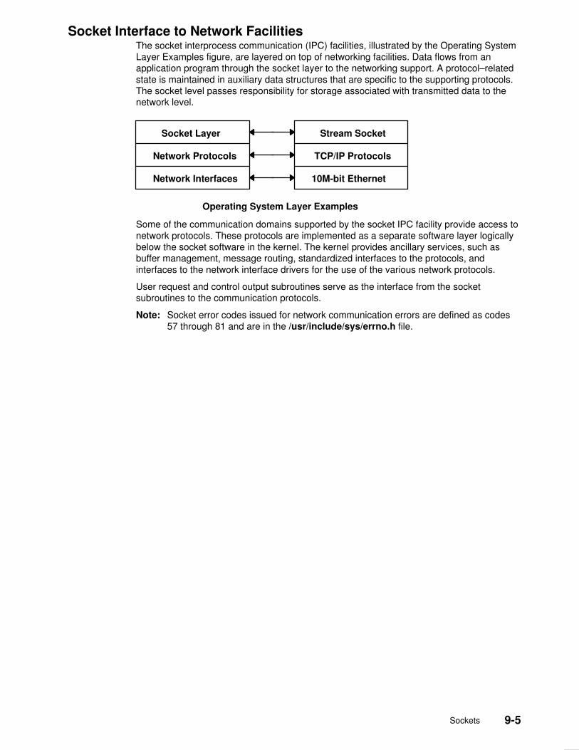
Sockets 9-5
Socket Interface to Network FacilitiesThe socket interprocess communication (IPC) facilities, illustrated by the Operating SystemLayer Examples figure, are layered on top of networking facilities. Data flows from anapplication program through the socket layer to the networking support. A protocol–relatedstate is maintained in auxiliary data structures that are specific to the supporting protocols.The socket level passes responsibility for storage associated with transmitted data to thenetwork level.
10M-bit EthernetNetwork Interfaces
TCP/IP Protocols
Stream Socket
Network Protocols
Socket Layer
Operating System Layer Examples
Some of the communication domains supported by the socket IPC facility provide access tonetwork protocols. These protocols are implemented as a separate software layer logicallybelow the socket software in the kernel. The kernel provides ancillary services, such asbuffer management, message routing, standardized interfaces to the protocols, andinterfaces to the network interface drivers for the use of the various network protocols.
User request and control output subroutines serve as the interface from the socketsubroutines to the communication protocols.
Note: Socket error codes issued for network communication errors are defined as codes57 through 81 and are in the /usr/include/sys/errno.h file.

9-6 AIX Communications Programming Concepts
Socket Subroutines Socket subroutines enable interprocess and network interprocess communications (IPC).Some socket routines are grouped together as the Socket Kernel Service subroutines.
Note: Do not call any Socket Kernel Service subroutines from kernel extensions.
The socket subroutines still maintained in the libc.a library are grouped together under theheading of Network Library Subroutines, on page 9-39. Application programs can use bothtypes of socket subroutines for IPC.

Sockets 9-7
Socket Header Files Socket header files contain data definitions, structures, constants, macros, and optionsused by socket subroutines. An application program must include the appropriate headerfile to make use of structures or other information a particular socket subroutine requires.Commonly used socket header files are:
/usr/include/netinet/in.h Defines Internet constants and structures.
/usr/include/arpa/nameser.h Contains Internet name server information.
/usr/include/netdb.h Contains data definitions for socket subroutines.
/usr/include/resolv.h Contains resolver global definitions and variables.
/usr/include/sys/socket.h Contains data definitions and socket structures.
/usr/include/sys/socketvar.h Defines the kernel structure per socket and containsbuffer queues.
/usr/include/sys/types.h Contains data type definitions.
/usr/include/sys/un.h Defines structures for the UNIX interprocesscommunication domain.
/usr/include/sys/ndd_var.h Defines structures for the AIX Network Device Driver(NDD) domain.
/usr/include/sys/atmsock.h Contains constants and structures for the AsynchronousTransfer Mode (ATM) protocol in the AIX NDD domain.
In addition to commonly used socket header files, Internet address translation subroutinesrequire the inclusion of the inet.h file. The inet.h file is located in the /usr/include/arpadirectory.

9-8 AIX Communications Programming Concepts
Socket Address Data StructuresThe socket data structure defines the socket. During a socket subroutine, the systemdynamically creates the socket data structure. The socket address is specified by a datastructure that is defined in a header file. See the sockaddr Structure figure for an illustrationof this data structure.
The /usr/include/sys/socket.h file contains the sockaddr structure. The contents of thesa_data structure depend on the protocol in use.
len socket address_data
2 bytes variable size
Family
sockaddr Structure
The types of socket–address data structures are as follows:
struct sockaddr_in Defines sockets used for machine–to–machine communicationacross a network and interprocess communication (IPC). The/usr/include/netinet/in.h file contains the sockaddr_instructure.
struct sockaddr_un Defines UNIX domain sockets used for local IPC only. Thesesockets require complete path name specification and do nottraverse networks. The /usr/include/sys/un.h file contains thesockaddr_un structure.
struct sockaddr_ns Defines the Xerox Network Services (XNS) sockets to be usedfor reliable, full–duplex, connection–oriented services to anapplication. The /usr/include/netns/ns.h file contains thesockaddr_ns structure.
struct sockaddr_ndd Defines the AIX NDD sockets used for machine–to–machinecommunication across a physical network. The/usr/include/sys/ndd_var.h file contains the sockaddr_nddstructure. Depending upon socket types and protocol, otherheader files may need to be included.

Sockets 9-9
Socket Communication Domains Sockets that share common communication properties, such as naming conventions andprotocol address formats, are grouped into communication domains. A communicationdomain is sometimes referred to as name or address space.
The communication domain includes the following:
• Rules for manipulating and interpreting names
• Collection of related address formats that comprise an address family
• Set of protocols, called the protocol family
Communication domains also consist of two categories, socket types and descriptors.Socket types include stream, datagram, sequenced packet, raw, and connection–orienteddatagram.
Address FormatsAn address format indicates what set of rules was used in creating network addresses of aparticular format. For example, in the Internet communication domain, a host address is a32–bit value that is encoded using one of four rules based on the type of network on whichthe host resides.
Each communication domain has different rules for valid socket names and interpretation ofnames. After a socket is created, it can be given a name according to the rules of thecommunication domain in which it was created. For example, in the UNIX communicationdomain, sockets are named with operating system path names. A socket can be named/dev/foo. Sockets normally exchange data only with sockets in the same communicationdomain.
Address FamiliesThe socket subroutine takes an address family as a parameter. Specifying an addressfamily indicates to the system how to interpret supplied addresses. The/usr/include/sys/socket.h and /usr/include/sys/socketvar.h files define the addressfamilies.
A socket subroutine that takes an address family (AF) as a parameter can use AF_UNIX(UNIX), AF_INET (Internet), AF_NS (Xerox Network Systems), or AF_NDD (AIX NetworkDevice Drivers) protocol. These address families are part of the following communicationdomains:
UNIX Provides socket communication between processes running on thesame operating system when an address family of AF_UNIX isspecified. A socket name in the UNIX domain is a string of ASCIIcharacters whose maximum length depends on the machine in use.
Internet Provides socket communication between a local process and a processrunning on a remote host when an address family of AF_INET isspecified. The Internet domain requires that Transmission ControlProtocol/Internet Protocol (TCP/IP) be installed on your system. Asocket name in the Internet domain is an Internet address, made up ofa 32–bit IP address and a 16–bit port address.
XNS Provides connection–oriented, reliable, full–duplex service to anapplication. A socket name in the XNS domain is made up of afour–byte network number, a six–byte host number, and a two–byte portnumber.

9-10 AIX Communications Programming Concepts
NDD Provides socket communication between a local process and a processrunning on a remote host when an address family of AF_NDD isspecified. The NDD domain enables applications to run directly on topof physical networks. This is in contrast to the Internet domain, in whichapplications run on top of transport protocols such as TCP, or UserDatagram Protocol (UDP). A socket name in the NDD domain consistsof AIX NDD name and a second part that is protocol dependent.
Communication domains are described by a domain data structure that is loadable.Communication protocols within a domain are described by a structure that is defined withinthe system for each protocol implementation configured. When a request is made to createa socket, the system uses the name of the communication domain to search linearly the listof configured domains. If the domain is found, the domain’s table of supported protocols isconsulted for a protocol appropriate for the type of socket being created or for a specificprotocol request. (A wildcard entry may exist for a raw domain.) Should multiple protocolentries satisfy the request, the first is selected.
UNIX Domain PropertiesCharacteristics of the UNIX domain are:
Types of sockets In the UNIX domain, the SOCK_STREAM socket type providespipe–like facilities, while the SOCK_DGRAM andSOCK_SEQPACKET socket types usually provide reliablemessage–style communications.
Naming Socket names are strings and appear in the file system name spacethrough portals.
Internet Domain PropertiesCharacteristics of the Internet domain are:
Socket typesand protocols
The SOCK_STREAM socket type is supported by the Internet TCPprotocol; the SOCK_DGRAM socket type, by the UDP protocol. Each islayered atop the transport–level IP. The Internet Control MessageProtocol (ICMP) is implemented atop or beside IP and is accessiblethrough a raw socket.
Naming Sockets in the Internet domain have names composed of a 32–bitInternet address and a 16–bit port number. Options can be used toprovide IP source routing or security options. The 32–bit address iscomposed of network and host parts; the network part is variable in sizeand is frequency encoded. The host part can be interpreted optionallyas a subnet field plus the host on a subnet; this is enabled by setting anetwork address mask.
Raw access The Internet domain allows a program with root–user authority accessto the raw facilities of IP. These interfaces are modeled as SOCK_RAWsockets. Each raw socket is associated with one IP protocol numberand receives all traffic for that protocol. This allows administrative anddebugging functions to occur and enables user–level implementationsof special–purpose protocols such as inter–gateway routing protocols.

Sockets 9-11
XNS Domain PropertiesA characteristic of the Xerox Network System (XNS) domain is the SOCK_SEQPACKETsocket type, which provides reliable message–style communications.
AIX Network Device Driver (NDD) Domain PropertiesCharacteristics of the AIX NDD domain are:
Socket typesand protocols
The SOCK_DGRAM socket type is supported by the connectionlessdatagram protocols. These include Ethernet, token ring, FiberDistributed Data Interface (FDDI), and FCS protocols. This socket typeallows applications to send and receive datagrams directly over thesemedia types. The SOCK_CONN_DGRAM socket type is supported byconnection–oriented datagram protocols. Currently, AsynchronousTransfer Mode (ATM) is the only protocol defined for this socket type.This socket type has the property of connection–oriented, unreliable,message delivery service.
Naming Sockets in the NDD domain have names composed of the AIX NDDname and a second part that is protocol dependent. For example, forATM, this part contains a 20–byte destination address and subaddress.

9-12 AIX Communications Programming Concepts
Socket Addresses Sockets can be named with an address so that processes can connect to them. The socketlayer treats an address as an opaque object. Applications supply and receive addresses astagged, variable–length byte strings. Addresses always reside in a memory buffer (mbuf) onentry to the socket layer. A data structure called a sockaddr can be used as a template forreferring to the identifying tag of each socket address.
Each address–family implementation includes subroutines for address family–specificoperations. When addresses must be manipulated (for example, to compare them forequality) a pointer to the address (a sockaddr structure) is used to extract the addressfamily tag. This tag is then used to identify the subroutine to invoke the desired operation.
Socket Address StorageAddresses passed by an application program commonly reside in mbufs only long enoughfor the socket layer to pass them to the supporting protocol for transfer into a fixed–sizedaddress structure. This occurs, for example, when a protocol records an address in aprotocol control block. The sockaddr structure is the common means by which the socketlayer and network–support facilities exchange addresses. The size of the generic data arraywas chosen to be large enough to hold most addresses directly. Communications domainsthat support larger addresses may ignore the array size.
• The UNIX communication domain stores file–system path names in mbufs and allowssocket names as large as 108 bytes.
• The Internet communication domain uses a structure that combines an Internet addressand a port number. The Internet protocols reserve space for addresses in an Internetcontrol–block data structure and free up mbufs that contain addresses after copying theircontents.
Socket Addresses in TCP/IPTransmission Control Protocol/Internet Protocol (TCP/IP) provides a set of 16–bit portnumbers within each host. Because each host assigns port numbers independently, it ispossible for ports on different hosts to have the same port number. TCP/IP creates thesocket address as an identifier that is unique throughout all Internet networks. TCP/IPconcatenates the Internet address of the local host interface with the port number to devisethe Internet socket address.
With TCP/IP, sockets are not tied to a destination address. Applications sending messagescan specify a different destination address for each datagram, if necessary, or they can tiethe socket to a specific destination address for the duration of the connection.
Since the Internet address is always unique to a particular host on a network, the socketaddress for a particular socket on a particular host is unique. Additionally, since eachconnection is fully specified by the pair of sockets it joins, every connection between Internethosts is also uniquely identified.
The port numbers up to 255 are reserved for official Internet services. Port numbers in therange of 256–1023 are reserved for other well–known services that are common on Internetnetworks. When a client process needs one of these well–known services at a particularhost, the client process sends a service request to the socket address for the well–knownport at the host.
If a process on the host is listening at the well–known port, the server process eitherservices the request using the well–known port or transfers the connection to another portthat is temporarily assigned for the duration of the connection to the client. Usingtemporarily–assigned (or secondary) ports frees the well–known port and allows the hostwell–known port to handle additional requests concurrently.
Sockets 9-13
The port numbers for well–known ports are listed in the /etc/services file. The port numbersabove 1023 are generally used by processes that need a temporary port once an initialservice request has been received. These port numbers are generated randomly and usedon a first–come, first–served basis.
Socket Addresses in AIX Network Device Driver (NDD)In the AIX NDD domain, socket addresses contain the NDD name, which associates thesocket with the local device (or adapter). Socket addresses also contain aprotocol–dependent part.
Typically, applications use the bind subroutine to bind a socket to a particular local deviceand 802.2 service access point (SAP). The information used to bind to a particular NDD andpacket type are specified in the NDD socket address passed into the bind subroutine. Oncethe socket is bound, it can be used to receive packets for the bound SAP addressed to thelocal host’s medium access control (MAC) address (or the broadcast address) for thatdevice. Raw packets can be transmitted using the send, sendto, and sendmsg socketsubroutines.
The protocol–dependent parts of the AIX NDD socket address structure are defined asfollows:
Ethernet The Ethernet NDD sockaddr is defined in the sys/ndd_var.h file. Thesockaddr structure name is sockaddr_ndd_8022. This sockaddrallows you to bind to an Ethernet type number or an 802.2 SAP number.Once bound to a particular type or SAP, a socket can be used to receivepackets of that type or SAP. Packets to be transmitted must becomplete Ethernet packets that include the MAC and logical link control(LLC) headers.
Token Ring The token–ring NDD sockaddr is defined in the sys/ndd_var.h file.The sockaddr structure name is sockaddr_ndd_8022. This sockaddrallows you to bind to an 802.2 SAP number. Once bound to a particulartype or SAP, a socket can be used to receive packets of that type orSAP. Packets to be transmitted must be complete token ring packetsthat include the MAC and LLC headers.
FDDI The Fiber Distributed Data Interface (FDDI) NDD sockaddr is definedin the sys/ndd_var.h file. The sockaddr structure name issockaddr_ndd_8022. This sockaddr allows you to bind to an 802.2SAP number. Once bound to a particular type or SAP, a socket can beused to receive packets of that type or SAP. Packets to be transmittedmust be complete FDDI packets that include the MAC and LLCheaders.
FCS The FCS NDD sockaddr is defined in the sys/ndd_var.h file. Thesockaddr structure name is sockaddr_ndd_8022. This sockaddrallows you to bind to an 802.2 SAP number. Once bound to a type orSAP, a socket can be used to receive packets of that type or SAP.Packets to be transmitted must be complete FCS packets that includethe MAC and LLC headers.
ATM Defined in the sockaddr_ndd_atm structure in the /sys/atmsock.h file.The sndd_atm_vc_type field specifies CONN_PVC or CONN_SVC, forAsynchronous Transfer Mode (ATM) permanent virtual circuit (PVC)and ATM switched virtual circuit (SVC), respectively. For ATM PVCs, thefirst four octets of the sndd_atm_addr field contain the virtual pathidentifier:virtual channel identifier (VPI:VCI) for a virtual circuit. For ATMSVCs, the sndd_atm_addr field contains the 20–octet ATM address,and the sndd_atm_subaddr field contains the 20–octet ATMsubaddress, if applicable.

9-14 AIX Communications Programming Concepts
AIX NDD protocols that support 802.2 LLC encapsulation use the sockaddr_ndd_8022structure for defining the NDD and 802.2 SAP to be used for input filtering. Currently, theonly NDD protocol that does not use this structure is ATM. The sockaddr_ndd_8022structure contains the following fields:
sndd_8022_len Contains the socket address length.
sndd_8022_family Contains the socket address family (for example, AF_NDD).
sndd_8022_nddname[NDD_MAXNAMELEN]
Contains the NDD device name for the Ethernet device (forexample, ent0).
sndd_8022_filterlen Contains the size of the remaining fields that define the inputfilter. For 802.2 encapsulated protocols, this is the size of structns_8022.
sndd_8022_ns Contains the filter structure and allows the application to specifythe types of packets to be received by this socket. This structurecontains the following fields:
filtertype Contains the type of filter. This includes 802.2LCC, 802.2 Logical Link Control/Sub–NetworkAccess Protocol (LLC/SNAP), as well asstandard Ethernet. A special ”wildcard” filtertype is supported that allows ALL packets to bereceived. This type, NS_TAP, and all standardfilter types are defined in the sys/ndd_var.hfile.
dsap For 802.2 LLC filters, this specifies the SAPused for filtering incoming packets. Theapplication ”binds” to this SAP and thenreceives packets addressed to this SAP, forexample, 0xaa for 802.2 LLC/SNAPencapsulations.
orgcode[3] For 802.2 LLC filters, this specifies theorganization code.
ethertype For 802.2 LLC SNAP and standard Ethernetfilter types, this field specifies the ethertype. Anexample is 0x800 for IP over Ethernet and IPover 802.2 LLC/SNAP encapsulations.

Sockets 9-15
Socket Types and ProtocolsSocket subroutines take socket types and socket protocols as parameters. An applicationprogram specifying a socket type indicates the desired communication style for that socketor socket pair. An application program specifying a socket protocol indicates the desiredtype of service. This service must be within the allowable services of the protocol family.
Socket TypesSockets are classified according to communication properties. Processes usuallycommunicate between sockets of the same type. However, if the underlying communicationprotocols support the communication, sockets of different types can communicate.
Each socket has an associated type, which describes the semantics of communicationsusing that socket. The socket type determines the socket communication properties such asreliability, ordering, and prevention of duplication of messages. The basic set of socket typesis defined in the sys/socket.h file:
/*Standard socket types */
#define SOCK_STREAM 1 /*virtual circuit*/
#define SOCK_DGRAM 2 /*datagram*/
#define SOCK_RAW 3 /*raw socket*/
#define SOCK_RDM 4 /*reliably–delivered message*/
#define SOCK_CONN_DGRAM 5 /*connection datagram*/
Other socket types can be defined.
The AIX operating system supports the following basic set of sockets:
SOCK_DGRAM Provides datagrams, which are connectionless messages of afixed maximum length. This type of socket is generally used forshort messages, such as a name server or time server, sincethe order and reliability of message delivery is not guaranteed.
In the UNIX domain, the SOCK_DGRAM socket type is similarto a message queue. In the Internet domain, theSOCK_DGRAM socket type is implemented on the UserDatagram Protocol/Internet Protocol (UDP/IP) protocol.
A datagram socket supports the bidirectional flow of data, whichis not sequenced, reliable, or unduplicated. A process receivingmessages on a datagram socket may find messages duplicatedor in an order different than the order sent. Record boundariesin data, however, are preserved. Datagram sockets closelymodel the facilities found in many contemporarypacket–switched networks.
SOCK_STREAM Provides sequenced, two–way byte streams with a transmissionmechanism for stream data. This socket type transmits data ona reliable basis, in order, and with out–of–band capabilities.
In the UNIX domain, the SOCK_STREAM socket type workslike a pipe. In the Internet domain, the SOCK_STREAM sockettype is implemented on the Transmission ControlProtocol/Internet Protocol (TCP/IP) protocol.
A stream socket provides for the bidirectional, reliable,sequenced, and unduplicated flow of data without recordboundaries. Aside from the bidirectionality of data flow, a pair ofconnected stream sockets provides an interface nearly identicalto pipes.
9-16 AIX Communications Programming Concepts
SOCK_RAW Provides access to internal network protocols and interfaces.Available only to individuals with root user authority, a rawsocket allows an application direct access to lower–levelcommunication protocols. Raw sockets are intended foradvanced users who wish to take advantage of some protocolfeature that is not directly accessible through a normal interface,or who wish to build new protocols atop existing low–levelprotocols.
Raw sockets are normally datagram–oriented, though theirexact characteristics are dependent on the interface provided bythe protocol.
SOCK_SEQPACKET Provides sequenced, reliable, and unduplicated flow ofinformation.
SOCK_CONN_DGRAM Provides connection–oriented datagram service. This type ofsocket supports the bidirectional flow of data, which issequenced and unduplicated, but is not reliable. Since this is aconnection–oriented service, the socket must be connectedprior to data transfer. Currently, only the Asynchronous TransferMode (ATM) protocol in the Network Device Driver (NDD)domain supports this socket type.
The SOCK_DGRAM and SOCK_RAW socket types allow an application program to senddatagrams to correspondents named in send subroutines. Application programs canreceive datagrams through sockets using the recv subroutines. The Protocol parameter isimportant when using the SOCK_RAW socket type to communicate with low–level protocolsor hardware interfaces. The application program must specify the address family in whichthe communication takes place.
The SOCK_STREAM socket types are full–duplex byte streams. A stream socket must beconnected before any data can be sent or received on it. When using a stream socket fordata transfer, an application program needs to perform the following sequence:
1. Create a connection to another socket with the connect subroutine.
2. Use the read and write subroutines or the send and recv subroutines to transfer data.
3. Use the close subroutine to finish the session.
An application program can use the send and recv subroutines to manage out–of–banddata.
SOCK_STREAM communication protocols are designed to prevent the loss or duplicationof data. If a piece of data for which the peer protocol has buffer space cannot besuccessfully transmitted within a reasonable period of time, the connection is broken. Whenthis occurs, the socket subroutine indicates an error with a return value of –1 and the errnoglobal variable is set to ETIMEDOUT. If a process sends on a broken stream, a SIGPIPEsignal is raised. Processes that cannot handle the signal terminate. When out–of–band dataarrives on a socket, a SIGURG signal is sent to the process group.
The process group associated with a socket can be read or set by either the SIOCGPGRPor SIOCSPGRP ioctl operation. To receive a signal on any data, use both the SIOCSPGRPand FIOASYNC ioctl operations. These operations are defined in the sys/ioctl.h file.

Sockets 9-17
Socket ProtocolsA protocol is a standard set of rules for transferring data, such as UDP/IP and TCP/IP. Anapplication program can specify a protocol only if more than one protocol is supported forthis particular socket type in this domain.
Each socket can have a specific protocol associated with it. This protocol is used within thedomain to provide the semantics required by the socket type. Not all socket types aresupported by each domain; support depends on the existence and implementation of asuitable protocol within the domain.
The /usr/include/sys/socket.h file contains a list of socket protocol families. The followinglist provides examples of protocol families (PF) found in the socket header file:
PF_UNIX Local communication
PF_INET Internet (TCP/IP)
PF_NS Xerox Network System (XNS) architecture
PF_NDD AIX NDD
These protocols are defined to be the same as their corresponding address families in thesocket header file. Before specifying a protocol family, the programmer should check thesocket header file for currently supported protocol families. Each protocol family consists ofa set of protocols. Major protocols in the suite of Internet Network Protocols include:
• TCP
• UDP
• IIP
• Internet Control Message Protocol (ICMP)
Read more about these protocols in ”Internet Transport–Level Protocols” in AIX 4.3 SystemManagement Guide: Communications and Networks.

9-18 AIX Communications Programming Concepts
Socket Creation The basis for communication between processes centers on the socket mechanism. Thesocket is comparable to the operating system file–access mechanism that provides an endpoint for communication. Application programs request the operating system to create asocket through the use of socket subroutines. Subroutines used to create sockets are:
• socket
• socketpair
When an application program requests the creation of a new socket, the operating systemreturns an integer that the application program uses to reference the newly created socket.The socket descriptor is an unsigned integer that is the lowest unused number usable for adescriptor. The descriptor is indexed to the kernel descriptor table. A process can obtain asocket descriptor table by creating a socket or inheriting one from a parent process.
To create a socket with the socket subroutine, the application program must include acommunication domain and a socket type. Also, it may include a specific communicationprotocol within the specified communication domain.
For additional information about creating sockets, read the following concepts:
• Socket Header Files, on page 9-7
• Socket Connections, on page 9-21

Sockets 9-19
Binding Names to Sockets The socket subroutine creates a socket without a name. An unnamed socket is one withoutany association to local or destination addresses. Until a name is bound to a socket,processes have no way to reference it and consequently, no message can be received on it.
Communicating processes are bound by an association. The bind subroutine allows aprocess to specify half of an association: local address, local port, or local path name. Theconnect and accept subroutines are used to complete a socket’s association. Each domainassociation can have a different composite of addresses. The following domain associationsare:
Internet domain Produces an association composed of local and foreign addressesand local and foreign ports.
UNIX domain Produces an association composed of local and foreign path names.
XNS domain (Xerox Network Systems domain) Produces reliable, full–duplex,connection–oriented services to an application.
NDD domain (AIX Network Device Driver) Provides an association composed oflocal device name (AIX NDD name) and foreign addresses, the formof which depends on the protocol being used.
An application program may not care about the local address it uses and may allow theprotocol software to select one. This is not true for server processes. Server processes thatoperate at a well–known port need to be able to specify that port to the system.
In most domains, associations must be unique. Internet domain associations must neverinclude duplicate protocol, local address, local port, foreign address, or foreign port tuples.
UNIX domain sockets need not always be bound to a name, but when bound can neverinclude duplicate protocol, local path name, or foreign path name tuples. The path namescannot refer to files already on the system.
The bind subroutine accepts the Socket, Name, and NameLength parameters. The Socketparameter is the integer descriptor of the socket to be bound. The Name parameterspecifies the local address, and the NameLength parameter indicates the length of addressin bytes. The local address is defined by a data structure termed sockaddr.
In the Internet domain, a process does not have to bind an address and port number to asocket, because the connect and send subroutines automatically bind an appropriateaddress if they are used with an unbound socket.
In the NDD domain, a process must bind a local NDD name to a socket.
The bound name is a variable–length byte string that is interpreted by the supportingprotocols. Its interpretation can vary from communication domain to communication domain(this is one of the properties of the domain). In the Internet domain, a name contains anInternet address, a length, and a port number. In the UNIX domain, a name contains a pathname, a length, and an address family, which is always AF_UNIX.
Binding Addresses to SocketsBinding addresses to sockets in the Internet domain demands a number of considerations.Port numbers are allocated out of separate spaces, one for each system and one for eachdomain on that system.
Note: Since the association is created in two steps, the association uniquenessrequirement indicated previously could be violated unless care is taken. Further,user programs do not always know proper values to use for the local address andlocal port since a host can reside on multiple networks, and the set of allocated portnumbers is not directly accessible to a user.
Wildcard addressing is provided to aid local address binding in the Internet domain. Whenan address is specified as INADDR_ANY (a constant defined in the netinet/in.h file), thesystem interprets the address as any valid address.
9-20 AIX Communications Programming Concepts
Sockets with wildcard local addresses may receive messages directed to the specified portnumber and sent to any of the possible addresses assigned to a host. If a server processwished to connect only hosts on a given network, it would bind the address of the hosts onthe appropriate network.
A local port can be specified or left unspecified (denoted by 0), in which case the systemselects an appropriate port number for it.
The restriction on allocating ports was done to allow processes executing in a secureenvironment to perform authentication based on the originating address and port number.For example, the rlogin(1) command allows users to log in across a network without beingasked for a password, if two conditions hold:
• The name of the system the user is logging in from is located in the /etc/hosts.equiv fileon the system that the user is trying to log in to (or the system name and the user nameare in the user’s .rhosts file in the user’s home directory).
• The user’s login process is coming from a privileged port on the machine from which theuser is logging in.
The port number and network address of the machine from which the user is logging in canbe determined either by the From parameter result of the accept subroutine, or from thegetpeername subroutine.
In certain cases, the algorithm used by the system in selecting port numbers is unsuitablefor an application program. This is because associations are created in a two–step process.For example, the Internet File Transfer Protocol (FTP) specifies that data connections mustalways originate from the same local port. However, duplicate associations are avoided byconnecting to different foreign ports. In this situation, the system disallows binding the samelocal address and port number to a socket if a previous data connection socket still exists.To override the default port selection algorithm, a setsockopt subroutine must beperformed before address binding.
The socket subroutine creates a socket without any association to local or destinationaddresses. For the Internet protocols, this means no local protocol port number has beenassigned. In many cases, application programs do not care about the local address theyuse and are willing to allow the protocol software to choose one for them. However, serverprocesses that operate at a well–known port must be able to specify that port to the system.Once a socket has been created, a server uses the bind subroutine to establish a localaddress for it.
Not all possible bindings are valid. For example, the caller might request a local protocolport that is already in use by another program, or it might request an invalid local Internetaddress. In such cases, the bind subroutine is unsuccessful and returns an error message.
Obtaining Socket AddressesNew sockets sometimes inherit the set of open sockets that created them. The socketsprogram interface includes subroutines that allow an application to obtain the address of thedestination to which a socket connects and the local address of a socket. The socketsubroutines that allow a program to retrieve socket addresses are:
• getsockname• getpeername
For additional information that you may need before binding or obtaining socket addresses,read the following concepts:
• Socket Header Files, on page 9-7• Socket Addresses, on page 9-12• Socket Connections, on page 9-21

Sockets 9-21
Socket Connections Initially, a socket is created in the unconnected state, meaning the socket is not associatedwith any foreign destination. The connect subroutine binds a permanent destination to asocket, placing it in the connected state. An application program must call the connectsubroutine to establish a connection before it can transfer data through a reliable streamsocket. Sockets used with connectionless datagram services need not be connected beforethey are used, but connecting sockets makes it possible to transfer data without specifyingthe destination each time.
The semantics of the connect subroutine depend on the underlying protocols. Anapplication program desiring reliable stream delivery service in the Internet family shouldselect the Transmission Control Protocol (TCP). In such cases, the connect subroutinebuilds a TCP connection with the destination and returns an error if it cannot. In the case ofconnectionless services, the connect subroutine does nothing more than store thedestination address locally. Similarly, application programs desiring connection–orienteddatagram service in the AIX Network Device Driver (NDD) family should select theAsynchronous Transfer Mode (ATM) protocol. Connection in the ATM protocol establishes apermanent virtual circuit (PVC) or switched virtual circuit (SVC). For PVCs, the local stationis set up, and there is no network activity. For SVCs, the virtual circuit is set up end–to–endin the network with the remote station.
Connections are established between a client process and a server process. In aconnection–oriented network environment, a client process initiates a connection and aserver process receives, or responds to, a connection. The client and server interactionsoccur as follows:
• The server, when willing to offer its advertised services, binds a socket to a well–knownaddress associated with the service, and then passively listens on its socket. It is thenpossible for an unrelated process to rendezvous with the server.
• The server process socket is marked to indicate incoming connections are to beaccepted on it.
• The client requests services from the server by initiating a connection to the server’ssocket. The client process uses a connect subroutine to initiate a socket connection.
• If the client process’ socket is unbound at the time of the connect call, the systemautomatically selects and binds a name to the socket if necessary. This is the usual waythat local addresses are bound to a socket.
• The system returns an error if the connection fails (any name automatically bound by thesystem, however, remains). Otherwise, the socket is associated with the server and datatransfer can begin.
Server ConnectionsIn the Internet domain, the server process creates a socket, binds it to a well–knownprotocol port, and waits for requests. If the server process uses a reliable stream delivery orthe computing response takes a significant amount of time, it may be that a new requestarrives before the server finishes responding to an old request. The listen subroutine allowsserver processes to prepare a socket for incoming connections. In terms of underlyingprotocols, the listen subroutine puts the socket in a passive mode ready to acceptconnections. When the server process starts the listen subroutine, it also informs theoperating system that the protocol software should queue multiple simultaneous requeststhat arrive at a socket. The listen subroutine includes a parameter that allows a process tospecify the length of the request queue for that socket. If the queue is full when aconnection request arrives, the operating system refuses the connection by discarding therequest. The listen subroutine applies only to sockets that have selected reliable streamdelivery or connection–oriented datagram service.

9-22 AIX Communications Programming Concepts
A server process uses the socket, bind, and listen subroutines to create a socket, bind it toa well–known protocol address, and specify a queue length for connection requests.Invoking the bind subroutine associates the socket with a well–known protocol port, but thesocket is not connected to a specific foreign destination. The server process may specify awildcard allowing the socket to receive a connection request from an arbitrary client.
All of this applies to the connection–oriented datagram service in the NDD domain, exceptthat the server process binds the locally created socket to an AIX NDD name and specifiesATM B–LLI and B–HLI parameters before calling the listen subroutine. If only B–LLI isspecified, all incoming calls (or connections), regardless of the B–HLI value, will be passedto this application.
Once a socket has been set up, the server process needs to wait for a connection. Theserver process waits for a connection by using the accept subroutine. A call to the acceptsubroutine blocks until a connection request arrives. When a request arrives, the operatingsystem returns the address of the client process that has placed the request. The operatingsystem also creates a new socket that has its destination connected to the requesting clientprocess and returns the new socket descriptor to the calling server process. The originalsocket still has a wildcard foreign destination that remains open.
When a connection arrives, the call to the accept subroutine returns. The server processcan either handle requests interactively or concurrently. In the interactive approach, theserver handles the request itself, closes the new socket, and then starts the acceptsubroutine to obtain the next connection request. In the concurrent approach, after the callto the accept subroutine returns, the server process forks a new process to handle therequest. The new process inherits a copy of the new socket, proceeds to service therequest, and then exits. The original server process must close its copy of the new socketand then invoke the accept subroutine to obtain the next connection request.
If a select call is made on a file descriptor of a socket waiting to perform an acceptsubroutine on the connection, when the ready message is returned it does not mean thatdata is there, only that the request was successfully completed. Now it is possible to startthe select subroutine on the returned socket descriptor to see if data is available for aconversation on the message socket.
The concurrent design for server processes results in multiple processes using the samelocal protocol port number. In TCP–style communication, a pair of end points define aconnection. Thus, it does not matter how many processes use a given local protocol portnumber as long as they connect to different destinations. In the case of a concurrent server,there is one process per client and one additional process that accepts connections. Themain server process has a wildcard for the destination, allowing it to connect with anarbitrary foreign site. Each remaining process has a specific foreign destination. When aTCP data segment arrives, it is sent to the socket connected to the segment’s source. If nosuch socket exists, the segment is sent to the socket that has a wildcard for its foreigndestination. Furthermore, because the socket with a wildcard foreign destination does nothave an open connection, it only honors TCP segments that request a new connection.
Sockets 9-23
Connectionless Datagram ServicesThe operating system provides support for connectionless interactions typical of thedatagram facilities found in packet–switched networks. A datagram socket provides asymmetric interface to data exchange. While processes are still likely to be client and server,there is no requirement for connection establishment. Instead, each message includes thedestination address.
An application program can create datagram sockets using the socket subroutine. In theInternet domain, if a particular local address is needed, a bind subroutine must precede thefirst data transmission. Otherwise, the operating system sets the local address or port whendata is first sent. In the NDD domain, bind must precede the first data transmission. Theapplication program uses the sendto and recvfrom subroutines to transmit data; thesecalls include parameters that allow the client process to specify the address of the intendedrecipient of the data.
In addition to the sendto and recvfrom calls, datagram sockets can also use the connectsubroutine to associate a socket with a specific destination address. In this case, any datasent on the socket is automatically addressed to the connected peer socket, and only datareceived from that peer is delivered to the client process. Only one connected address ispermitted for each socket at one time; a second connect subroutine changes thedestination address.
A connect subroutine request on a datagram socket results in the operating systemrecording the peer socket’s address (as compared to a stream socket, where a connectrequest initiates establishment of an end–to–end connection). The accept and listensubroutines are not used with datagram sockets.
While a datagram socket is connected, errors from recent send subroutines can be returnedasynchronously. These errors can be reported on subsequent operations on the socket, or aspecial socket option, SO_ERROR. This option, when used with the getsockoptsubroutine, can be used to interrogate the error status. A select subroutine for reading orwriting returns true when a process receives an error indication. The next operation returnsthe error, and the error status is cleared.
Read the following concepts for more information that you may need before connectingsockets:
• Socket Header Files, on page 9-7
• Socket Types and Protocols, on page 9-15

9-24 AIX Communications Programming Concepts
Socket Options In addition to binding a socket to a local address or connecting it to a destination address,application programs need a method to control the socket. For example, when usingprotocols that use time out and retransmission, the application program may want to obtainor set the time–out parameters. An application program may also want to control theallocation of buffer space, determine if the socket allows transmission of broadcast, orcontrol processing of out–of–band data. The ioctl–style getsockopt and setsockoptsubroutines provide the means to control socket operations. The getsockopt subroutineallows an application program to request information about socket options. The setsockoptsubroutine allows an application program to set a socket option using the same set ofvalues obtained with the getsockopt subroutine. Not all socket options apply to all sockets.The options that can be set depend on the current state of the socket and the underlyingprotocol being used.
For additional information that you may need when obtaining or setting socket options, readthe following concepts:
• Socket Header Files, on page 9-7
• Socket Types and Protocols, on page 9-15
• Out–of–Band Data, on page 9-25
• IP Multicasts, on page 9-29.

Sockets 9-25
Socket Data Transfer Most of the work performed by the socket layer is in sending and receiving data. The socketlayer itself explicitly refrains from imposing any structure on data transmitted or receivedthrough sockets. Any data interpretation or structuring is logically isolated in theimplementation of the communication domain.
Once a connection is established between sockets, an application program can send andreceive data. Sending and receiving data can be done with any one of several subroutines.The subroutines vary according to the amount of information to be transmitted and receivedand the state of the socket being used to perform the operation.
• The write subroutine can be used with a socket that is in a connected state, as thedestination of the data is implicitly specified by the connection.
• The sendto and sendmsg subroutines allow the process to specify the destination for amessage explicitly.
• The read subroutine allows a process to receive data on a connected socket withoutreceiving the sender’s address.
• The recvfrom and recvmsg subroutines allow the process to retrieve the incomingmessage and the sender’s address.
The applicability of the above subroutines varies from domain to domain and from protocolto protocol.
While the send and recv subroutines are virtually identical to the read and writesubroutines, the extra flags argument in the send and recv subroutines is important. Theflags, defined in the sys/socket.h file, can be defined as a nonzero value if the applicationprogram requires one or more of the following:
MSG_OOB Sends or receives out–of–band data.
MSG_PEEK Looks at data without reading.
MSG_DONTROUTE Sends data without routing packets.
MSG_MPEG2 Sends MPEG2 video data blocks.
Out–of–band data is specific to stream sockets. The option to have data sent without routingapplied to the outgoing packets is currently used only by the routing table managementprocess, and is unlikely to be of interest to the casual user. The ability to preview data is,however, of general interest. When the MSG_PEEK flag is specified with a recv subroutine,any data present is returned to the user, but treated as still unread. That is, the next read orrecv subroutine applied to the socket returns the data previously previewed.
Out–of–Band DataThe stream socket abstraction includes the concept of out–of–band data. Out–of–band(OOB) data is a logically independent transmission channel associated with each pair ofconnected stream sockets. Out–of–band data can be delivered to the socket independentlyof the normal receive queue or within the receive queue depending upon the status of theSO_OOBINLINE socket–level option. The abstraction defines that the out–of–band datafacilities must support the reliable delivery of at least one out–of–band message at a time.This message must contain at least one byte of data, and at least one message can bepending delivery to the user at any one time.
For communication protocols that support only in–band signaling (that is, the urgent data isdelivered in sequence with the normal data), the operating system normally extracts thedata from the normal data stream and stores it separately. This allows users to choosebetween receiving the urgent data in order and receiving it out of sequence without havingto buffer all the intervening data.

9-26 AIX Communications Programming Concepts
It is possible to peek at out–of–band data. If the socket has a process group, a SIGURGsignal is generated when the protocol is notified of out–of–band data. A process can set theprocess group or process ID to be informed by the SIGURG signal through a SIOCSPGRPioctl call.
Note: The /usr/include/sys/ioctl.h file contains the ioctl definitions and structures for usewith socket ioctl calls.
If multiple sockets have out–of–band data awaiting delivery, an application program can usea select subroutine for exceptional conditions to determine those sockets with such datapending. Neither the signal nor the select indicates the actual arrival of the out–of–banddata, but only notification that is pending.
In addition to the information passed, a logical mark is placed in the data stream to indicatethe point at which the out–of–band data was sent. When a signal flushes any pendingoutput, all data up to the mark in the data stream is discarded.
To send an out–of–band message, the MSG_OOB flag is supplied to a send or sendtosubroutine. To receive out–of–band data, an application program must set the MSG_OOBflag when performing a recvfrom or recv subroutine.
An application program can determine if the read pointer is currently pointing at the logicalmark in the data stream, by using the SIOCATMARK ioctl call.
A process can also read or peek at the out–of–band data without first reading up to thelogical mark. This is more difficult when the underlying protocol delivers the urgent datain–band with the normal data, and only sends notification of its presence ahead of time (thatis, the TCP protocol used to implement streams in the Internet domain). With suchprotocols, the out–of–band byte may not have arrived when a recv subroutine is performedwith the MSG_OOB flag. In that case, the call will return an EWOULDBLOCK error code.There may be enough in–band data in the input buffer that normal flow control prevents thepeer from sending the urgent data until the buffer is cleared. The process must then readenough of the queued data that the urgent data can be delivered.
Certain programs that use multiple bytes of urgent data and must handle multiple urgentsignals need to retain the position of urgent data within the stream. The socket–level option,SO_OOINLINE provides the capability. With this option, the position of the urgent data (thelogical mark) is retained. The urgent data immediately follows the mark within the normaldata stream that is returned without the MSG_OOB flag. Reception of multiple urgentindications causes the mark to move, but no out–of–band data is lost.

Sockets 9-27
Socket I/O ModesSockets can be set to either blocking or nonblocking I/O mode. The FIONBIO ioctl operationis used to determine this mode. When the FIONBIO ioctl is set, the socket is markednonblocking. If a read is tried and the desired data is not available, the socket does not waitfor the data to become available, but returns immediately with the EWOULDBLOCK errorcode.
Note: The EWOULDBLOCK error code is defined with the _BSD define and is equivalentto the EAGAIN error code.
When the FIONBIO ioctl is not set, the socket is in blocking mode. In this mode, if a read istried and the desired data is not available, the calling process waits for the data. Similarly,when writing, if FIONBIO is set and the output queue is full, an attempt to write causes theprocess to return immediately with an error code of EWOULDBLOCK.
When performing nonblocking I/O on sockets, a program must check for theEWOULDBLOCK error code (stored in the errno global variable). This occurs when anoperation would normally block, but the socket it was performed on is marked asnonblocking. The following socket subroutines return a EWOULDBLOCK error code:
• accept
• send
• recv
• read
• write
Processes using these subroutines should be prepared to deal with the EWOULDBLOCKerror code. For a nonblocking socket, the connect subroutine returns an EINPROGRESSerror code.
If an operation such as a send operation cannot be done completely, but partial writes arepermissible (for example when using a stream socket), the data that can be sentimmediately is processed, and the return value indicates the amount actually sent.

9-28 AIX Communications Programming Concepts
Socket Shutdown Once a socket is no longer required, the calling program can discard the socket by applyinga close subroutine to the socket descriptor. If a reliable delivery socket has data associatedwith it when a close takes place, the system continues to attempt data transfer. However, ifthe data is still undelivered, the system discards the data. Should the application programhave no use for any pending data, it can use the shutdown subroutine on the socket priorto closing it.
Closing SocketsClosing a socket and reclaiming its resources is not always a straightforward operation. Incertain situations, such as when a process exits, a close subroutine is never expected to beunsuccessful. However, when a socket promising reliable delivery of data is closed with datastill queued for transmission or awaiting acknowledgment of reception, the socket mustattempt to transmit the data. If the socket discards the queued data to allow the closesubroutine to complete successfully, it violates its promise to deliver data reliably. Discardingdata can cause naive processes, which depend upon the implicit semantics of the closecall, to work unreliably in a network environment. However, if sockets block until all data hasbeen transmitted successfully, in some communication domains a close subroutine maynever complete.
The socket layer compromises in an effort to address this problem and maintain thesemantics of the close subroutine. In normal operation, closing a socket causes anyqueued but unaccepted connections to be discarded. If the socket is in a connected state, adisconnect is initiated. The socket is marked to indicate that a file descriptor is no longerreferencing it, and the close operation returns successfully. When the disconnect requestcompletes, the network support notifies the socket layer, and the socket resources arereclaimed. The network layer may attempt to transmit any data queued in the socket’s sendbuffer, although this is not guaranteed.
Alternatively, a socket may be marked explicitly to force the application program to lingerwhen closing until pending data are flushed and the connection has shutdown. This optionis marked in the socket data structure using the setsockopt subroutine with theSO_LINGER option. The setsockopt subroutine, using the linger option, takes a lingerstructure. When an application program indicates that a socket is to linger, it also specifies aduration for the lingering period. If the lingering period expires before the disconnect iscompleted, the socket layer forcibly shuts down the socket, discarding any data stillpending.

Sockets 9-29
IP Multicasts The use of Internet Protocol (IP) multicasting enables a message to be transmitted to agroup of hosts, instead of having to address and send the message to each group memberindividually. Internet addressing provides for Class D addressing that is used formulticasting.
When a datagram socket is defined, the setsockopt subroutine can be modified. To join orleave a multicast group, use the setsockopt subroutine with the IP_ADD_MEMBERSHIP orIP_DROP_MEMBERSHIP flags. The interface that is used and the group used are specifiedin an ip_mreq structure that contains the following fields:
struct ip_mreq{
struct in_addr imr.imr_interface.s_addr;
struct in_addr imr.imr_multiaddr.s_addr;
}
The in_addr structure is defined as:
struct in_addr{
ulong s_addr;
}
In order to send to a multicasting group it is not necessary to join the groups. For receivingtransmissions sent to a multicasting group, membership is required. For multicast sending,use an IP_MULTICAST_IF flag with the setsockopt subroutine. This specifies the interfaceto be used. It may be necessary to call the setsockopt subroutine with theIP_MULTICAST_LOOP flag in order to control the loopback of multicast packets. Bydefault, packets are delivered to all members of the multicast group including the sender, if itis a member. However, this can be disabled with the setsockopt subroutine using theIP_MULTICAST_LOOP flag.
The setsockopt subroutine flags that are required for multicast communication and usedwith the IPPROTO_IP protocol level follow:
IP_ADD_MEMBERSHIP Joins a multicast group as specified in the OptionValueparameter of type struct ip_mreq. A maximum of 20groups may be joined per socket.
IP_DROP_MEMBERSHIP Leaves a multicast group as specified in the OptionValueparameter of type struct ip_mreq. Only allowable forprocesses with a user ID (UID) value of zero.
IP_MULTICAST_IF Permits sending of multicast messages on an interface asspecified in the OptionValue parameter of type structip_addr. An address of INADDR_ANY (0x000000000)removes the previous selection of an interface in themulticast options. If no interface is specified then theinterface leading to the default route is used.
IP_MULTICAST_LOOP Sets multicast loopback, determining whether or nottransmitted messages are delivered to the sending host. AnOptionValue parameter of type char is used to controlloopback being on or off.
IP_MULTICAST_TTL Sets the time–to–live (TTL) for multicast packets. AnOptionValue parameter of type char is used to set thisvalue between 0 and 255.

9-30 AIX Communications Programming Concepts
The following examples demonstrate the use of the setsockopt function with the protocollevel set to Internet Protocol (IPPROTO_IP).
To mark a socket for sending to a multicast group on a particular interface:
struct ip_mreq imr;
setsockopt(s, IPPROTO_IP, IP_MULTICAST_IF,
&imr.imr_interface.s_addr, sizeof(struct in_addr));
To disable the loopback on a socket:
char loop = 0;
setsockopt(s, IPPROTO_IP, IP_MULTICAST_LOOP, &loop,
sizeof(char));
To allow address reuse for binding multiple multicast applications to the same IP groupaddress:
int on = 1;
setsockopt(s, SOL_SOCKET, SO_REUSEADDR, &on, sizeof(int));
To join a multicast group for receiving:
struct ip_mreq imr;
setsockopt(s, IPPROTO_IP, IP_ADD_MEMBERSHIP, &imr, sizeof(struct
ip_mreq));
To leave a multicast group:
struct ip_mreq imr;
setsockopt(s, IPPROTO_IP, IP_DROP_MEMBERSHIP, &imr, sizeof(struct
ip_mreq));
The getsockopt function can also be used with the multicast flags to obtain informationabout a particular socket.
IP_MULTICAST_IF Retrieves the interface’s IP address.
IP_MULTICAST_LOOP Retrieves the specified looping mode from the multicastoptions.
IP_MULTICAST_TTL Retrieves the time–to–live in the multicast options.
Sockets 9-31
Network Address Translation Network library subroutines enable an application program to locate and construct networkaddresses while using interprocess communication facilities in a distributed environment.
Locating a service on a remote host requires many levels of mapping before client andserver can communicate. A network service is assigned a name that is intended to beunderstandable for a user; such as ”the login server on host prospero.” This name and thename of the peer host must then be translated into network addresses. Finally, the addressmust then be used to determine a physical location and route to the service.
Network library subroutines map:
• Host names to network addresses
• Network names to network numbers
• Protocol names to protocol numbers
• Service names to port numbers
Additional network library subroutines exist to simplify the manipulation of names andaddresses.
An application program must include the netdb.h file when using any of the network librarysubroutines.
Note: All networking services return values in standard network byte order.
Name ResolutionThe process of obtaining an Internet address from a host name is known as nameresolution and is done by the gethostbyname subroutine. The process of translating anInternet address into a host name is known as reverse name resolution and is done by thegethostbyaddr subroutine.
When a process receives a symbolic host name and needs to resolve it into an address, itcalls a resolver routine.
Resolver routines on hosts running Transmission Control Protocol/Internet Protocol(TCP/IP) attempt to resolve names using the following sources:
• BIND/DNS (domain name server, named)
• Network Information Service (NIS)
• Local /etc/hosts file
To resolve a name in a domain network, the resolver routine first queries the domain nameserver database, which may be local if the host is a domain name server or may be on aforeign host. Name servers translate domain names into Internet addresses. The group ofnames for which a name server is responsible is its zone of authority. If the resolver routineis using a remote name server, the routine uses the Domain Name Protocol (DOMAIN) toquery for the mapping. To resolve a name in a flat network, the resolver routine checks foran entry in the local /etc/hosts file. When NIS is used, the /etc/hosts file on the masterserver is checked.
By default, resolver routines attempt to resolve names using the above resources.BIND/DNS will be tried first. If the /etc/resolv.conf file does not exist or if BIND/DNS couldnot find the name, NIS is queried if it is running. If NIS is not running, then the local/etc/hosts file is searched. If none of these services could find the name then the resolverroutines return with HOST_NOT_FOUND. If all of the services were unavailable, then theresolver routines return with SERVICE_UNAVAILABLE.

9-32 AIX Communications Programming Concepts
The default order can be overwritten by creating the configuration file, /etc/netsvc.conf andspecifying the desired order. Both the default and /etc/netsvc.conf can be overwritten withthe environment variable NSORDER. If either the /etc/netsvc.conf file or environmentvariable NSORDER are defined, then at least one value must be specified along with theoption.
To specify host ordering with the /etc/netsvc.conf file:
hosts = value,value,value
where value is one of the listed sources.
To specify host ordering with the NSORDER environment variable:
NSORDER=value,value,value
The order is specifed on one line with values separated by commas. White spaces arepermitted between the commas and the equal sign. The values specified and their orderingdepends on the network configuration. For example, if the local network is organized as aflat network, then only the /etc/hosts file is needed.
The etc/netsvc.conf file would contain the following line:
hosts=local
The NSORDER environment variable would be set as:
NSORDER=local
If the local network is a domain network using a name server for name resolution and an/etc/hosts file for backup, then both services should be specified.
The etc/netsvc.conf file would contain the following line:
hosts=bind,local
The NSORDER environment variable would be set as:
NSORDER=bind,local
Note: The values listed must be in lowercase.
The first source in the list will be tried. The algorithm will try another specified service if the:
• current service is not running, therefore, it is unavailable
• current service could not find the name and is not authoritative.
If the /etc/resolv.conf file does not exist, then BIND/DNS is considered to be not set up orrunning and therefore not available. If the subroutines, getdomainname and yp_bind fail,then it is assumed that the NIS service is not set up or running and therefore not available. Ifthe /etc/hosts file could not be opened, then a local search is impossible and therefore thefile and service are unavailable.
A service listed as authoritative means that it is the expert of its successors and should havethe information requested. (The other services may contain only a subset of the informationin the authoritative service.) Name resolution will end after trying a service listed asauthoritative even if it does not find the name. If an authoritative service is not available,then the next service specified will be queried, otherwise the resolver routine will return withHOST_NOT_FOUND.
An authoritative service is specified with the string =auth directly behind a value. The entireword authoritative can be typed in, but only the auth will be used. For example, the/etc/netsvc.conf file could contain the following line:
hosts = nis=auth,bind,local
If NIS is running, then search is ended after the NIS query regardless of whether the namewas found. If NIS is not running, then the next source is queried, which is BIND.

Sockets 9-33
TCP/IP name servers use caching to reduce the cost of searching for names of hosts onremote networks. Instead of searching anew for a host name each time a request is made,a name server looks at its cache to see if the host name was resolved recently. Sincedomain and host names do change, each item remains in the cache for a limited length oftime specified by the record’s time to live (TTL). In this way, authorities can specify how longthey expect the name resolution to be accurate.
In a DOMAIN name server environment, the host name set using the hostname commandfrom the command line or in the rc.net file format must be the official name of the host asreturned by the name server. Generally, this name is the full domain name of the host in theform:
host.subdomain.subdomain.rootdomain
If the host name is not set up as a fully qualified domain name, and if the system is set up touse a DOMAIN name server in conjunction with the sendmail program, the sendmailconfiguration file (/etc/sendmail.cf) must be edited to reflect this official host name. Inaddition, the domain name macros in this configuration file must be set for the sendmailprogram to operate correctly.
Note: The domain specified in the /etc/sendmail.cf file takes precedence over the domainset by the hostname command for all sendmail functions.
For a host that is in a domain network but is not a name server, the local domain name anddomain name server are specified in the /etc/resolv.conf file. In a domain name serverhost, the local domain and other name servers are defined in files read by the nameddaemon when it starts.
Host NamesThe following related network library subroutines map Internet host names to addresses:
• gethostbyaddr
• gethostbyname
• sethostent
• endhostent
The official name of the host and its public aliases are returned by the gethostbyaddr andgethostbyname subroutines, along with the address family and a null–terminated list ofvariable length addresses. The list of variable length addresses is required because it ispossible for a host to have many addresses with the same name.
The database for these calls is provided either by the /etc/hosts file or by use of a namedname server. Because of the differences in the databases and their access protocols, theinformation returned may differ. When using the host table version of the gethostbynamesubroutine, only one address is returned, but all listed aliases are included. The nameserver version may return alternate addresses but does not provide any aliases other thanthe one given as a parameter value.
Network NamesRelated network library subroutines to map network names to numbers and networknumbers to names are:
• getnetbyaddr
• getnetbyname
• getnetent
• setnetent
• endnetent

9-34 AIX Communications Programming Concepts
The getnetbyaddr, getnetbyname, and getnetent subroutines extract their informationfrom the /etc/networks file.
Protocol NamesRelated network library subroutines to map protocol names are:
• getprotobynumber
• getprotobyname
• getprotoent
• setprotoent
• endprotoent
The getprotobynumber, getprotobyname, and getprotoent subroutines extract theirinformation from the /etc/protocols file.
Service NamesRelated network library subroutines to map service names to port numbers are:
• getservbyname
• getservbyport
• getservent
• setservent
• endservent
A service is expected to reside at a specific port and employ a particular communicationprotocol. The expectation is consistent within the Internet domain, but inconsistent withinother network architectures. Further, a service can reside on multiple ports. If a serviceresides on multiple ports, the higher level library subroutines must be bypassed orextended. Services available are contained in the /etc/services file.
Network Byte–Order TranslationRelated network library subroutines to convert network address byte order are:
• htonl
• htons
• ntohl
• ntohs
Internet Address TranslationRelated network library subroutines to convert Internet addresses and dotted decimalnotation are:
• inet_addr
• inet_lnaof
• inet_makeaddr
• inet_netof
• inet_network
• inet_ntoa

Sockets 9-35
Network Host and Domain Names The hostid parameter is an integer that identifies the host machine. Host IDs fall under thecategory of Internet network addressing because, by convention, the 32–bit Internetaddress is used. The socket subroutines that manage the host ID are:
• gethostid
• sethostid
Socket subroutines to manage the internal host name are:
• gethostname
• sethostname
When a site obtains authority for part of the domain name space, it invents a string thatidentifies its piece of the space and uses that string as the name of the domain. To managethe domain name, applications can use the following socket subroutines:
• getdomainname
• setdomainname

9-36 AIX Communications Programming Concepts
Domain Name Resolution When a process receives a symbolic name and needs to resolve it into an address, it calls aresolver subroutine. The method used by the set of resolver subroutines to resolve namesdepends on the local host configuration. In addition, the organization of the networkdetermines how a resolver subroutine communicates with remote name server hosts (thehosts that resolve names for other hosts).
A resolver subroutine determines which type of network it is dealing with by determiningwhether the /etc/resolv.conf file exists. If the file exists, a resolver subroutine assumes thatthe local network has a name server. Otherwise, it assumes that no name server is present.
To resolve a name with no name server present, a resolver subroutine checks the/etc/hosts file for an entry that maps the name to an address.
To resolve a name in a name server network, a resolver subroutine first queries the domainname server (DNS) database, which may be local host (if the host is a domain name server)or a foreign host. If the subroutine is using a remote name server, the subroutine uses theDomain Name Protocol (DOMAIN) to query for the mapping. If this query is unsuccessful,the subroutine then checks for an entry in the local /etc/hosts file.
The resolver subroutines are used to make, send, and interpret packets for name servers inthe Internet domain. Together, the following resolver subroutines form the set of functionsthat resolve domain names:
• res_init
• res_mkquery
• res_search
• res_query
• res_send
• dn_comp
• dn_expand
• getshort
• getlong
• putshort
• putlong
Note: The res_send subroutine does not perform interactive queries and expects thename server to handle recursion.
Global information used by these resolver subroutines is kept in the _res structure. Thisstructure is defined in the /usr/include/resolv.h file and contains the following members:
Member Contents
int Denotes the retrans field.
int Denotes the retry field.
long Denotes the options field.
int Denotes the nscount field.
struct Denotes the sockaddr_in and nsaddr_list [MAXNS] fields.
ushort Denotes the ID field.
char Denotes the defdname [MAXDNAME] field.
#define Denotes the nsaddr nsaddr_list [0] field.

Sockets 9-37
The options field of the _res structure is constructed by logically ORing the following values:
RES_INIT Indicates whether the initial name server and default domain namehave been initialized (that is, whether the res_init subroutine hasbeen called).
RES_DEBUG Prints debugging messages.
RES_USEVC Uses Transmission Control Protocol/Internet Protocol (TCP/IP)connections for queries instead of User Datagram Protocol/InternetProtocol (UDP/IP).
RES_STAYOPEN Used with the RES_USEVC value, keeps the TCP/IP connectionopen between queries. While UDP/IP is the mode normally used,TCP/IP mode and this option are useful for programs that regularlyperform many queries.
RES_RECURSE Sets the Recursion Desired bit for queries. This is the default.
RES_DEFNAMES Appends the default domain name to single–label queries. This is thedefault.
Three environment variables affect values related to the _res structure:
LOCALDOMAIN Overrides the default local domain, which is read from the/etc/resolv.conf file and stored in the defdname field of the _resstructure.
RES_TIMEOUT Overrides the default value of the retrans field of the _res structure,which is the value of the RES_TIMEOUT constant defined in the/usr/include/resolv.h file. This value is the base time–out period inseconds between queries to the name servers. After each failedattempt, the time–out period is doubled. The time–out period isdivided by the number of name servers defined. The minimumtime–out period is 1 second.
RES_RETRY Overrides the default value for the retry field of the _res structure,which is 4. This value is the number of times the resolver tries toquery the name servers before giving up. Setting RES_RETRY to 0prevents the resolver from querying the name servers.

9-38 AIX Communications Programming Concepts
Socket Examples The socket examples are programming fragments that illustrate a socket function. Theycannot be used in an application program without modification. They are intended only forillustrative purposes and are not for use within a program.
• Socketpair Communication Example Program, on page 9-42
• Reading Internet Datagrams Example Program, on page 9-43
• Sending Internet Datagrams Example Program, on page 9-44
• Reading UNIX Datagrams Example Program, on page 9-45
• Sending UNIX Datagrams Example Program, on page 9-46
• Initiating Internet Stream Connections Example Program, on page 9-47
• Accepting Internet Stream Connections Example Program, on page 9-48
• Checking for Pending Connections Example Program, on page 9-50
• Initiating UNIX Stream Connections Example Program, on page 9-52
• Accepting UNIX Stream Connections Example Program, on page 9-53
• Sending Data on an ATM Socket PVC Client Example Program, on page 9-54
• Receiving Data on an ATM Socket PVC Server Example Program, on page 9-56
• Sending Data on an ATM Socket Rate–Enforced SVC Client Example Program, on page 9-58
• Receiving Data on an ATM Socket Rate–Enforced SVC Server Example Program, on page 9-63
• Sending Data on an ATM Socket SVC Client Example Program, on page 9-66
• Receiving Data on an ATM Socket SVC Server Example Program, on page 9-69
• Receiving Packets Over Ethernet Example Program, on page 9-72
• Sending Packets Over Ethernet Example Program, on page 9-74
• Analyzing Packets Over the Network Example Program, on page 9-77
Note: All socket applications must be compiled with _BSD set to a specific value.Acceptable values are 43 and 44. In addition, most applications should probablyinclude the Berkeley Software Distribution (BSD) libbsd.a library.

Sockets 9-39
List of Socket Programming References The list includes:
• Kernel Service Subroutines
• Network Library Subroutines
• Header Files
• Protocols
• Example Programs
Kernel Service Subroutines
accept Accepts a connection on a socket to create a new socket.
bind Binds a name to a socket.
connect Connects two sockets.
getdomainname Gets the name of the current domain.
gethostid Gets the unique identifier of the current host.
gethostname Gets the unique name of the current host.
getpeername Gets the name of the peer socket.
getsockname Gets the socket name.
getsockopt Gets options on sockets.
listen Listens for socket connections and limits the backlog of incomingconnections.
recv Receives messages from connected sockets.
recvfrom Receives messages from sockets.
recvmsg Receives a message from any socket.
send Sends messages from a connected socket.
sendmsg Sends a message from a socket by using a message structure.
sendto Sends messages through a socket.
send_file Sends the contents of a file through a socket.
setdomainname Sets the name of the current domain.
sethostid Sets the unique identifier of the current host.
sethostname Sets the unique name of the current host.
setsockopt Sets socket options.
shutdown Shuts down all socket send and receive operations.
socket Creates an end point for communication and returns a descriptor.
socketpair Creates a pair of connected sockets.
Network Library Subroutines
dn_comp Compresses a domain name.
dn_expand Expands a compressed domain name.
endhostent Ends retrieval of network host entries.
endnetent Closes the networks file.
endprotoent Closes the /etc/protocols file.

9-40 AIX Communications Programming Concepts
endservent Closes the /etc/service file entry.
gethostbyaddr Gets network host entry by address.
gethostbyname Gets network host entry by name.
gethostent Gets host entry from the /etc/hosts file.
getnetbyaddr Gets network entry by address.
getnetbyname Gets network entry by name.
getnetent Gets network entry.
getprotobyname Gets protocol entry from the /etc/protocols file by protocol name.
getprotobynumber
Gets a protocol entry from the /etc/protocols file by number.
getprotoent Gets protocol entry from the /etc/protocols file.
_getlong Retrieves long byte quantities.
_getshort Retrieves short byte quantities.
getservbyname Gets service entry by name.
getservbyport Gets service entry by port.
getservent Gets services file entry.
htonl Converts an unsigned long integer from host byte order toInternet–network byte order.
htons Converts an unsigned short integer from host byte order toInternet–network byte order.
inet_addr Converts Internet addresses to Internet numbers.
inet_lnaof Separates local Internet addresses into their network number andlocal network address.
inet_makeaddr Makes an Internet address.
inet_netof Separates network Internet addresses into their network number andlocal network address.
inet_network Converts Internet network addresses in . (dot) notation to Internetnumbers.
inet_ntoa Converts an Internet address into an ASCII string.
ntohl Converts an unsigned long integer from Internet–network standardbyte order to host byte order.
ntohs Converts an unsigned short integer from Internet–network byte orderto host byte order.
_putlong Places long byte quantities into the byte stream.
_putshort Places short byte quantities into the byte stream.
rcmd Allows execution of commands on a remote host.
res_init Searches for a default domain name and Internet address.
res_mkquery Makes query messages for name server.
res_query Provides an interface to the server query mechanism.
res_search Makes a query and awaits a response.
res_send Sends a query to a name server and retrieves a response.
rexec Allows command execution on a remote host.
rresvport Retrieves a socket with a privileged address.
ruserok Allows servers to authenticate clients.
sethostent Opens network host file.

Sockets 9-41
setnetent Opens and rewinds the network file.
setprotoent Opens and rewinds the /etc/protocols file.
setservent . Opens and rewinds the service file.
Header Files
/usr/include/netinet/in.h Defines Internet constants and structures.
/usr/include/arpa/nameser.h Contains Internet name–server information.
/usr/include/netdb.h Contains data definitions for socket subroutines.
/usr/include/resolv.h Contains resolver global definitions and variables.
/usr/include/sys/socket.h Contains data definitions and socket structures.
/usr/include/sys/socketvar.h Defines the kernel structure per socket and containsbuffer queues.
/usr/include/sys/types.h Contains data type definitions.
/usr/include/sys/un.h Defines structures for the UNIX InterprocessCommunication domain.
Protocols
PF_UNIX Local communication
PF_INET Internet (TCP/IP)
PF_NS Xerox Network System (XNS) architecture
Example ProgramsSocketpair Communication Example Program
Checking for Pending Connections Example Program
Reading Internet Datagrams Example Program
Sending Internet Datagrams Example Program
Initiating Internet Stream Connections Example Program
Accepting Internet Stream Connections Example Program
Reading UNIX Datagrams Example Program
Sending UNIX Datagrams Example Program
Initiating a UNIX Stream Connection Example Program
Accepting UNIX Stream Connections Example Program
Sending Data on an ATM Socket PVC Client Example Program
Receiving Data on an ATM Socket PVC Server Example Program
Sending Data on an ATM Socket Rate–Enforced SVC Client Example Program
Receiving Data on an ATM Socket Rate–Enforced SVC Server Example Program
Sending Data on an ATM Socket SVC Client Example Program
Receiving Data on an ATM Socket SVC Server Example Program
Receiving Packets Over Ethernet Example Program
Sending Packets Over Ethernet Example Program
Analyzing Packets Over the Network Example Program

9-42 AIX Communications Programming Concepts
Socketpair Communication Example /* This program fragment creates a pair of connected sockets then
* forks and communicates over them. Socket pairs have a two–way
* communication path. Messages can be sent in both directions.
*/
#include <stdio.h>
#include <sys/socket.h>
#include <sys/types.h>
#define DATA1 ”In Xanadu, did Kublai Khan...”
#define DATA2 ”A stately pleasure dome decree...”
main()
{
int sockets[2], child;
char buf[1024];
if (socketpair(AF_UNIX, SOCK_STREAM, 0, sockets) < 0) {
perror(”opening stream socket pair”);
exit(1);
}
if ((child = fork()) == –1)
perror(”fork”);
else if (child) { /* This is the parent. */
close(sockets[0]);
if (read(sockets[1], buf, 1024, 0) < 0)
perror(”reading stream message”);
printf(”––>%s\n”, buf);
if (write(sockets[1], DATA2, sizeof(DATA2)) < 0)
perror(”writing stream message”);
close(sockets[1]);
} else { /* This is the child. */
close(sockets[1]);
if (write(sockets[0], DATA1, sizeof(DATA1)) < 0)
perror(”writing stream message”);
if (read(sockets[0], buf, 1024, 0) < 0)
perror(”reading stream message”);
printf(”––>%s\n”, buf);
close(sockets[0]);
}
}

Sockets 9-43
Reading Internet Datagrams Example Program /*
* This program creates a datagram socket, binds a name to it,
and
* then reads from the socket.
*/
#include <sys/types.h>
#include <sys/socket.h>
#include <netinet/in.h>
#include <stdio.h>
main()
{
int sock, length;
struct sockaddr_in name;
char buf[1024];
/* Create a socket from which to read. */
sock = socket(AF_INET, SOCK_DGRAM, 0);
if (sock < 0) {
perror(”opening datagram socket”);
exit(1);
}
/* Create name with wildcards. */
name.sin_family = AF_INET;
name.sin_addr.s_addr = INADDR_ANY;
name.sin_port = 0;
if (bind(sock, (struct sockaddr *)&name, sizeof(name))) {
perror(”binding datagram socket”);
exit(1);
}
/* Find assigned port value and print it out. */
length = sizeof(name);
if (getsockname(sock, (struct sockaddr *)&name, &length)) {
perror(”getting socket name”);
exit(1);
}
printf(”Socket has port #%d\n”, ntohs(name.sin_port));
/* Read from the socket. */
if (read(sock, buf, 1024) < 0)
perror(”receiving datagram packet”);
printf(”––>%s\n”, buf);
close(sock);
}
/*
* recvfrom() can also be used in place of the read. recvfrom()
* provides an extra field for setting flags. More explanation
* is available in Understanding Socket Data Transfer.
*/
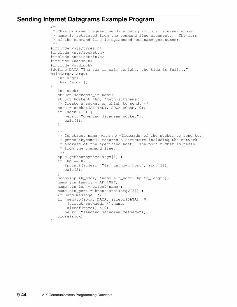
9-44 AIX Communications Programming Concepts
Sending Internet Datagrams Example Program /*
* This program fragment sends a datagram to a receiver whose
* name is retrieved from the command line arguments. The form
* of the command line is dgramsend hostname portnumber.
*/
#include <sys/types.h>
#include <sys/socket.h>
#include <netinet/in.h>
#include <netdb.h>
#include <stdio.h>
#define DATA ”The sea is calm tonight, the tide is full...”
main(argc, argv)
int argc;
char *argv[];
{
int sock;
struct sockaddr_in name;
struct hostent *hp, *gethostbyname();
/* Create a socket on which to send. */
sock = socket(AF_INET, SOCK_DGRAM, 0);
if (sock < 0) {
perror(”opening datagram socket”);
exit(1);
}
/*
* Construct name, with no wildcards, of the socket to send to. * gethostbyname() returns a structure including the network
* address of the specified host. The port number is taken
* from the command line.
*/
hp = gethostbyname(argv[1]);
if (hp == 0) {
fprintf(stderr, ”%s: unknown host”, argv[1]);
exit(2);
}
bcopy(hp–>h_addr, &name.sin_addr, hp–>h_length);
name.sin_family = AF_INET;
name.sin_len = sizeof(name);
name.sin_port = htons(atoi(argv[2]));
/* Send message. */
if (sendto(sock, DATA, sizeof(DATA), 0,
(struct sockaddr *)&name,
sizeof(name)) < 0)
perror(”sending datagram message”);
close(sock);
}

Sockets 9-45
Reading UNIX Datagrams Example Program #include <sys/types.h>
#include <sys/socket.h>
#include <sys/un.h>
#include <stdio.h>
#define NAME ”socket”
/*
* This program creates a UNIX domain datagram socket, binds a
* name to it, then reads from the socket.
*/
main()
{
int sock, length;
struct sockaddr_un name;
char buf[1024];
/* Create socket from which to read. */
sock = socket(AF_UNIX, SOCK_DGRAM, 0);
if (sock < 0) {
perror(”opening datagram socket”);
exit(1);
}
/* Create name. */
name.sun_family = AF_UNIX;
strcpy(name.sun_path, NAME);
name.sun_len = strlen(name.sun_path);
if (bind(sock, (struct sockaddr *)&name, SUN_LEN(&name))) {
perror(”binding name to datagram socket”);
exit(1);
}
printf(”socket ––>%s\n”, NAME);
/* Read from the socket. */
if (read(sock, buf, 1024) < 0)
perror(”receiving datagram packet”);
printf(”––>%s\n”, buf);
close(sock);
unlink(NAME);
}

9-46 AIX Communications Programming Concepts
Sending UNIX Datagrams Example Program /*
* This program fragment sends a datagram to a receiver whose
* name is retrieved from the command line arguments. The form
* of the command line is udgramsend pathname.
*/
#include <sys/types.h>
#include <sys/socket.h>
#include <sys/un.h>
#include <stdio.h>
#define DATA ”The sea is calm tonight, the tide is full...”
main(argc, argv)
int argc;
char *argv[];
{
int sock;
struct sockaddr_un name;
/* Create socket on which to send. */
sock = socket(AF_UNIX, SOCK_DGRAM, 0);
if (sock < 0) {
perror(”opening datagram socket”);
exit(1);
}
/* Construct name of socket to send to. */
name.sun_family = AF_UNIX;
strcpy(name.sun_path, argv[1]);
name.sun_len = strlen(name.sun_path);
/* Send message. */
if (sendto(sock, DATA, sizeof(DATA), 0, (struct sockaddr
*)&name,
sizeof(struct sockaddr_un)) < 0) {
perror(”sending datagram message”);
}
close(sock);
}
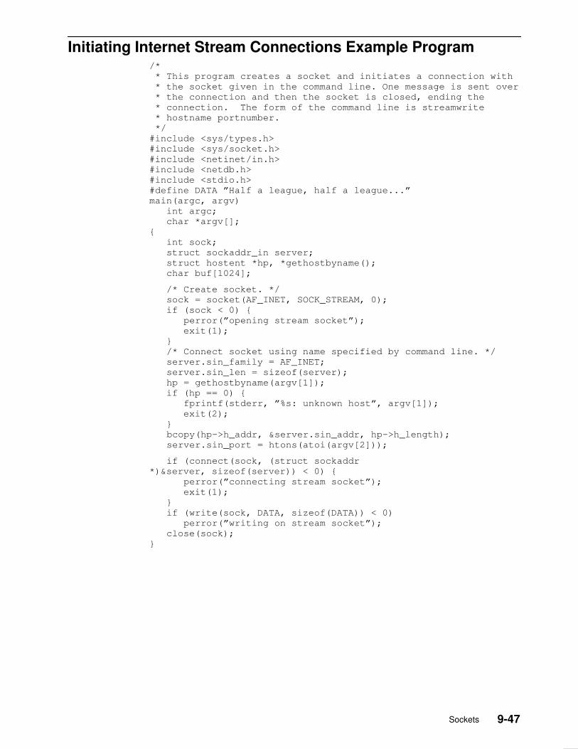
Sockets 9-47
Initiating Internet Stream Connections Example Program /*
* This program creates a socket and initiates a connection with
* the socket given in the command line. One message is sent over
* the connection and then the socket is closed, ending the
* connection. The form of the command line is streamwrite
* hostname portnumber.
*/
#include <sys/types.h>
#include <sys/socket.h>
#include <netinet/in.h>
#include <netdb.h>
#include <stdio.h>
#define DATA ”Half a league, half a league...”
main(argc, argv)
int argc;
char *argv[];
{
int sock;
struct sockaddr_in server;
struct hostent *hp, *gethostbyname();
char buf[1024];
/* Create socket. */
sock = socket(AF_INET, SOCK_STREAM, 0);
if (sock < 0) {
perror(”opening stream socket”);
exit(1);
}
/* Connect socket using name specified by command line. */
server.sin_family = AF_INET;
server.sin_len = sizeof(server);
hp = gethostbyname(argv[1]);
if (hp == 0) {
fprintf(stderr, ”%s: unknown host”, argv[1]);
exit(2);
}
bcopy(hp–>h_addr, &server.sin_addr, hp–>h_length);
server.sin_port = htons(atoi(argv[2]));
if (connect(sock, (struct sockaddr
*)&server, sizeof(server)) < 0) {
perror(”connecting stream socket”);
exit(1);
}
if (write(sock, DATA, sizeof(DATA)) < 0)
perror(”writing on stream socket”);
close(sock);
}

9-48 AIX Communications Programming Concepts
Accepting Internet Stream Connections Example Program /*
* This program creates a socket and begins an infinite loop.
* Each time through the loop it accepts a connection and prints
* out messages from it. When the connection breaks, or a
* termination message comes through, the program accepts a new
* connection.
*/
#include <sys/types.h>
#include <sys/socket.h>
#include <netinet/in.h>
#include <netdb.h>
#include <stdio.h>
#define TRUE 1
main()
{
int sock, length;
struct sockaddr_in server;
int msgsock;
char buf[1024];
int rval;
int i;
/* Create socket. */
sock = socket(AF_INET, SOCK_STREAM, 0);
if (sock < 0) {
perror(”opening stream socket”);
exit(1);
}
/* Name socket using wildcards. */
server.sin_family = AF_INET;
server.sin_len = sizeof(server);
server.sin_addr.s_addr = INADDR_ANY;
server.sin_port = 0;
if (bind(sock, (struct sockaddr *)&server, sizeof(server))) {
perror(”binding stream socket”);
exit(1);
}
/* Find out assigned port number and print it out. */
length = sizeof(server);
if (getsockname(sock, (struct sockaddr *)&server, &length)) {
perror(”getting socket name”);
exit(1);
}
printf(”Socket has port #%d\n”, ntohs(server.sin_port));

Sockets 9-49
/* Start accepting connection. */
listen(sock, 5);
do {
msgsock = accept(sock, 0, 0);
if (msgsock == –1) perror(”accept”);
else do {
bzero(buf, sizeof(buf));
if ((rval = read(msgsock, buf, 1024)) < 0)
perror(”reading stream message”);
i = 0;
if (rval == 0)
printf(”Ending connection\n”);
else
printf(”––>%s\n”, buf);
} while (rval != 0);
close(msgsock);
} while (TRUE);
/*
* Since this program has an infinite loop, the socket ”sock”
* is never explicitly closed. However, all sockets will be
* closed automatically when a process is killed or terminates
* normally.
*/
}

9-50 AIX Communications Programming Concepts
Checking for Pending Connections Example Program This program must be compiled with the –D_BSD and –lbsd options. For example, use thecc prog.c –o prog –D_BSD –lbsd command.
/*
* This program uses select() to check that someone is trying to
* connect before calling accept().
*/
#include <sys/select.h>
#include <sys/types.h>
#include <sys/socket.h>
#include <sys/time.h>
#include <netinet/in.h>
#include <netdb.h>
#include <stdio.h>
#define TRUE 1
main()
{
int sock, length;
struct sockaddr_in server;
int msgsock;
char buf[1024];
int rval;
fd_set ready;
struct timeval to;
/* Create socket. */
sock = socket(AF_INET, SOCK_STREAM, 0);
if (sock < 0) {
perror(”opening stream socket”);
exit(1);
}
/* Name socket using wildcards. */
server.sin_family = AF_INET;
server.sin_len = sizeof(server);
server.sin_addr.s_addr = INADDR_ANY;
server.sin_port = 0;
if (bind(sock, &server, sizeof(server))) {
perror(”binding stream socket”);
exit(1);
}
/* Find out assigned port number and print it out. */
length = sizeof(server);
if (getsockname(sock, &server, &length)) {
perror(”getting socket name”);
exit(1);
}
printf(”Socket has port #%d\n”, ntohs(server.sin_port));
/* Start accepting connections. */
listen(sock, 5);
do {
FD_ZERO(&ready);
FD_SET(sock, &ready);
to.tv_sec = 5;
to.tv_usec = 0;
if (select(sock + 1, &ready, 0, 0, &to) < 0) {
perror(”select”);
continue;
}

Sockets 9-51
/*
* When a select is done on a file descriptor of a socket
* waiting to do an accept on the connection, a select
* can be performed on the new descriptor to insure availability
* of the data.
*
* In this example, after accept returns, a read is done, but
* it would now be possible to select on the returned socket
* descriptor to see if data is available.
*/
if (FD_ISSET(sock, &ready)) {
msgsock = accept(sock, (struct sockaddr *)0, (int *)0);
if (msgsock == –1)
perror(”accept”);
else do {
bzero(buf, sizeof(buf));
if ((rval = read(msgsock, buf, 1024)) < 0)
perror(”reading stream message”);
else if (rval == 0)
printf(”Ending connection\n”);
else
printf(”––>%s\n”, buf);
} while (rval > 0);
close(msgsock);
} else
printf(”Do something else\n”);
} while (TRUE);
}
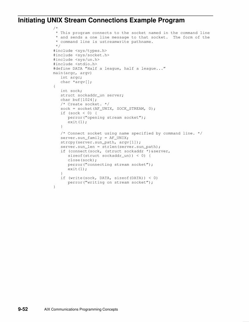
9-52 AIX Communications Programming Concepts
Initiating UNIX Stream Connections Example Program /*
* This program connects to the socket named in the command line
* and sends a one line message to that socket. The form of the
* command line is ustreamwrite pathname.
*/
#include <sys/types.h>
#include <sys/socket.h>
#include <sys/un.h>
#include <stdio.h>
#define DATA ”Half a league, half a league...”
main(argc, argv)
int argc;
char *argv[];
{
int sock;
struct sockaddr_un server;
char buf[1024];
/* Create socket. */
sock = socket(AF_UNIX, SOCK_STREAM, 0);
if (sock < 0) {
perror(”opening stream socket”);
exit(1);
}
/* Connect socket using name specified by command line. */
server.sun_family = AF_UNIX;
strcpy(server.sun_path, argv[1]);
server.sun_len = strlen(server.sun_path);
if (connect(sock, (struct sockaddr *)&server,
sizeof(struct sockaddr_un)) < 0) {
close(sock);
perror(”connecting stream socket”);
exit(1);
}
if (write(sock, DATA, sizeof(DATA)) < 0)
perror(”writing on stream socket”);
}

Sockets 9-53
Accepting UNIX Stream Connections Example Program /*
* This program creates a socket in the UNIX domain and binds a
* name to it. After printing the socket’s name, a loop begins.
* Each time through the loop it accepts a connection and prints
* out messages from it. When the connection breaks, or a
* termination message comes through, the program accepts a new
* connection.
*/
#include <sys/types.h>
#include <sys/socket.h>
#include <sys/un.h>
#include <stdio.h>
#define NAME ”socket”
main()
{
int sock, msgsock, rval;
struct sockaddr_un server;
char buf[1024];
/* Create socket. */
sock = socket(AF_UNIX, SOCK_STREAM, 0);
if (sock < 0) {
perror(”opening stream socket”);
exit(1);
}
/* Name socket using file system name. */
server.sun_family = AF_UNIX;
strcpy(server.sun_path, NAME);
server.sun_len = strlen(server.sun_path);
if (bind(sock, (struct sockaddr *)&server, SUN_LEN(&server))) {
perror(”binding stream socket”);
exit(1);
}
printf(”Socket has name %s\n”, server.sun_path);
/* Start accepting connections. */
listen(sock, 5);
for (;;) {
msgsock = accept(sock, 0, 0); if (msgsock == –1) perror(”accept”);
else do {
bzero(buf, sizeof(buf));
if ((rval = read(msgsock, buf, 1024)) < 0)
perror(”reading stream message”);
else if (rval == 0)
printf(”Ending connection\n”);
else
printf(”––>%s\n”, buf);
} while (rval > 0);
close(msgsock);
}
/* The following statements are not executed, because they
* follow an infinite loop. However, most ordinary programs
* will not run forever. In the UNIX domain it is necessary to
* tell the file system that you are through using NAME. In
* most programs you use the call unlink() as below. Since
* the user will have to kill this program, it will be
* necessary to remove the name with a shell command.
*/
close(sock);
unlink(NAME);
}

9-54 AIX Communications Programming Concepts
Sending Data on an ATM Socket PVC Client Example Program This program must be compiled with the –D_BSD and –lbsd options. For example, use thecc prog.c –o prog –D_BSD –lbsd command.
/*
*
* ATM Sockets PVC Client Example
*
* This program opens a PVC and sends data on it.
*
*/
#include <stdio.h>
#include <stddef.h>
#include <stdlib.h>
#include <errno.h>
#include <sys/socket.h>
#include <sys/ioctl.h>
#include <sys/ndd_var.h>
#include <sys/atmsock.h>
#define BUFF_SIZE 8192
char buff[BUFF_SIZE];
main(argc, argv)
int argc;
char *argv[];
{
int s; // Socket file descriptor
int error; // Function return code
sockaddr_ndd_atm_t addr; // ATM Socket Address
// Create a socket in the AF_NDD domain of type SOCK_CONN_DGRAM
// and NDD_PROT_ATM protocol.
s = socket(AF_NDD, SOCK_CONN_DGRAM, NDD_PROT_ATM);
if (s == –1) { // Socket either returns the file descriptor
perror(”socket”); // or a –1 to indicate an error.
exit(–1);
}
// The bind command associates this socket with a particular
// ATM device, as specified by addr.sndd_atm_nddname.
addr.sndd_atm_len = sizeof(addr);
addr.sndd_atm_family = AF_NDD;
strcpy( addr.sndd_atm_nddname, ”atm0” ); // The name of the ATM device
// which is to be used.
error = bind( s, (struct sockaddr *)&addr, sizeof(addr) );
if (error) { // An error from bind would indicate the
perror(”bind”); // requested ATM device is not available.
exit(–1); // Check smitty devices.
} /* endif */
// To open a PVC, the addr.sndd_atm_vc_type field of the
// sockaddr_ndd_atm is set to CONN_PVC. The VPI and VCI are
// specified in the fields sndd_atm_addr.number.addr[0] and
// sndd_atm_addr.number.addr[1].

Sockets 9-55
addr.sndd_atm_vc_type = CONN_PVC; // Indicates PVC
addr.sndd_atm_addr.number.addr[0] = 0; // VPI
addr.sndd_atm_addr.number.addr[1] = 15; // VCI
error = connect( s, (struct sockaddr *)&addr, sizeof(addr) );
if (error) { // A connect error may indicate that
perror(”connect”); // the VPI/VCI is already in use.
exit(–1);
} /* endif */
while (1) {
error = send( s, buff, BUFF_SIZE, 0 );
if (error < 0 ) { // Send returns –1 to
perror(”send”); // to indicate an error.
exit(–1); // The errno is set an can
} else { // be displayed with perror.
printf(”sent %d bytes\n”, error ); // Or it returns the
number
} // of bytes transmitted
sleep(1); // Just sleep 1 second, then send more data.
} /* endwhile */
exit(0);
}

9-56 AIX Communications Programming Concepts
Receiving Data on an ATM Socket PVC Server ExampleProgram
This program must be compiled with the –D_BSD and –lbsd options. For example, use thecc prog.c –o prog –D_BSD –lbsd command.
/*
* ATM Sockets PVC Server Example
*
* This program open a PVC an receives data on it.
*
*/
#include <stdio.h>
#include <stddef.h>
#include <stdlib.h>
#include <errno.h>
#include <sys/socket.h>
#include <sys/ioctl.h>
#include <sys/ndd_var.h>
#include <sys/atmsock.h>
#define BUFF_SIZE 8192
char buff[BUFF_SIZE];
main(argc, argv)
int argc;
char *argv[];
{
int s; // Socket file descriptor
int error; // Function return code
sockaddr_ndd_atm_t addr; // ATM Socket Address
// Create a socket in the AF_NDD domain of type SOCK_CONN_DGRAM
// and NDD_PROT_ATM protocol.
s = socket(AF_NDD, SOCK_CONN_DGRAM, NDD_PROT_ATM);
if (s == –1) { // Socket either returns the file descriptor
perror(”socket”); // or a –1 to indicate an error.
exit(–1);
}
// The bind command associates this socket with a particular
// ATM device, as specified by addr.sndd_atm_nddname.
addr.sndd_atm_len = sizeof(addr);
addr.sndd_atm_family = AF_NDD;
strcpy( addr.sndd_atm_nddname, ”atm0” ); // The name of the ATM device
// which is to be used.
error = bind( s, (struct sockaddr *)&addr, sizeof(addr) );
if (error) { // An error from bind would indicate the
perror(”bind”); // requested ATM device is not available.
exit(–1); // Check smitty devices.
} /* endif */
// To open a PVC, the addr.sndd_atm_vc_type field of the
// sockaddr_ndd_atm is set to CONN_PVC. The VPI and VCI are
// specified in the fields sndd_atm_addr.number.addr[0] and
// sndd_atm_addr.number.addr[1].
addr.sndd_atm_vc_type = CONN_PVC; // Indicates PVC
addr.sndd_atm_addr.number.addr[0] = 0; // VPI
addr.sndd_atm_addr.number.addr[1] = 15; // VCI
error = connect( s, (struct sockaddr *)&addr, sizeof(addr) );
if (error) { // A connect error may indicate that
perror(”connect”); // the VPI/VCI is already in use.
exit(–1);
} /* endif */

Sockets 9-57
while (1) {
error = recv( s, buff, BUFF_SIZE, 0 );
if (error < 0 ) { // Send returns –1 to
perror(”recv”); // to indicate an error.
exit(–1); // The errno is set ancan
} else { // be displayed with perror.
printf(”received %d bytes\n”, error ); // Or it returns the
number
} // of bytes received
} /* endwhile */
exit(0);
}

9-58 AIX Communications Programming Concepts
Sending Data on an ATM Socket Rate–Enforced SVC ClientExample Program
This program must be compiled with the –D_BSD and –lbsd options. For example, use thecc prog.c –o prog –D_BSD –lbsd command.
/*
* ATM Sockets rate enforced SVC Client Example
*
* This program opens a opens a rate enforced (not best effort)
SVC
* and sends data on it.
*
*/
#include <stdio.h>
#include <stddef.h>
#include <stdlib.h>
#include <errno.h>
#include <sys/socket.h>
#include <sys/ioctl.h>
#include <sys/ndd_var.h>
#include <sys/atmsock.h>
#define BUFF_SIZE 100000
char buff[BUFF_SIZE];
main(argc, argv)
int argc;
char *argv[];
{
int s; // Socket file descriptor
int error; // Function return code
int i;
sockaddr_ndd_atm_t addr; // ATM Socket Address
unsigned long size; // Size of socket argument
aal_parm_t aal_parm; // AAL parameters
blli_t blli[3]; // Broadband Lower Layer
Info
traffic_des_t traffic; // Traffic Descriptor
bearer_t bearer; // Broadband Bearer
Capability
int o[20]; // Temporary variable for
ATM
// address
cause_t cause; // Cause of failure
unsigned char max_pend; // Maximum outstanding
transmits
// Create a socket in the AF_NDD domain of type
SOCK_CONN_DGRAM
// and NDD_PROT_ATM protocol.
s = socket(AF_NDD, SOCK_CONN_DGRAM, NDD_PROT_ATM);
if (s == –1) {
perror(”socket”);
exit(–1);
}
addr.sndd_atm_len = sizeof(addr);
addr.sndd_atm_family = AF_NDD;
strcpy( addr.sndd_atm_nddname, ”atm0” );
// The bind command associates this socket with a particular
// ATM device, as specified by addr.sndd_atm_nddname.
error = bind( s, (struct sockaddr *)&addr, sizeof(addr) );
if (error) { // An error from bind would indicate the
perror(”bind”); // requested ATM device is not available.
exit(–1); // Check smitty devices.

Sockets 9-59
} /* endif */
// Set the AAL parameters.
// See the ATM UNI 3.0 for valid combinations.
// For a rate enforced connection the adapter will segment
// according to the fwd_max_sdu_size field. This means that
// although the client sends 100000 bytes at once, the server
// will receive them in packets the size of fwd_max_sdu_size.
bzero( aal_parm, sizeof(aal_parm_t) );
aal_parm.length = sizeof(aal_5_t);
aal_parm.aal_type = CM_AAL_5;
aal_parm.aal_info.aal5.fwd_max_sdu_size = 7708;
aal_parm.aal_info.aal5.bak_max_sdu_size = 7520;
aal_parm.aal_info.aal5.mode = CM_MESSAGE_MODE;
aal_parm.aal_info.aal5.sscs_type = CM_NULL_SSCS;
error = setsockopt( s, 0, SO_ATM_AAL_PARM, (void *)&aal_parm,
sizeof(aal_parm_t) );
if (error) {
perror(”setsockopt SO_AAL_PARM”);
exit(–1);
} /* endif */
// Up to three BLLI may be specified in the setup message.
// If a BLLI contains valid information, its length must be
// set to sizeof(blli_t). Otherwise set its length to 0.
// In this example the application specifies two BLLIs.
// After the connection has been established, the application
// can use getsockopt to see which BLLI was accepted by the
// called station.
bzero(blli, sizeof(blli_t) );
blli[0].length = sizeof(blli_t);
blli[1].length = sizeof(blli_t);
blli[2].length = 0;
blli[0].L2_prot = CM_L2_PROT_USER;
blli[0].L2_info = 1;
// Fields that are not used must be set to NOT_SPECIFIED_B
(byte)
blli[0].L2_mode = NOT_SPECIFIED_B;
blli[0].L2_win_size = NOT_SPECIFIED_B;
blli[0].L3_prot = NOT_SPECIFIED_B;
blli[0].L3_mode = NOT_SPECIFIED_B;
blli[0].L3_def_pkt_size = NOT_SPECIFIED_B;
blli[0].L3_pkt_win_size = NOT_SPECIFIED_B;
blli[0].L3_info = NOT_SPECIFIED_B;
blli[0].ipi = NOT_SPECIFIED_B;
blli[0].snap_oui[0] = NOT_SPECIFIED_B;
blli[0].snap_oui[1] = NOT_SPECIFIED_B;
blli[0].snap_oui[2] = NOT_SPECIFIED_B;
blli[0].snap_pid[0] = NOT_SPECIFIED_B;
blli[0].snap_pid[1] = NOT_SPECIFIED_B;
// Up to three blli may be specified in the setup message.
// The caller must query the blli with getsockopt to see which
// blli the other side accepted.
blli[1].L2_prot = CM_L2_PROT_USER;
blli[1].L2_info = 2;
// Fields that are not used must be set to NOT_SPECIFIED_B
(byte)
blli[1].L2_mode = NOT_SPECIFIED_B;
blli[1].L2_win_size = NOT_SPECIFIED_B;
blli[1].L3_prot = NOT_SPECIFIED_B;
blli[1].L3_mode = NOT_SPECIFIED_B;
blli[1].L3_def_pkt_size = NOT_SPECIFIED_B;
blli[1].L3_pkt_win_size = NOT_SPECIFIED_B;
blli[1].L3_info = NOT_SPECIFIED_B;
blli[1].ipi = NOT_SPECIFIED_B;
blli[1].snap_oui[0] = NOT_SPECIFIED_B;
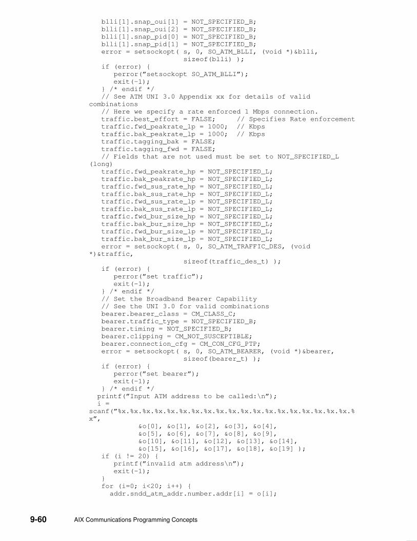
9-60 AIX Communications Programming Concepts
blli[1].snap_oui[1] = NOT_SPECIFIED_B;
blli[1].snap_oui[2] = NOT_SPECIFIED_B;
blli[1].snap_pid[0] = NOT_SPECIFIED_B;
blli[1].snap_pid[1] = NOT_SPECIFIED_B;
error = setsockopt( s, 0, SO_ATM_BLLI, (void *)&blli,
sizeof(blli) );
if (error) {
perror(”setsockopt SO_ATM_BLLI”);
exit(–1);
} /* endif */
// See ATM UNI 3.0 Appendix xx for details of valid
combinations
// Here we specify a rate enforced 1 Mbps connection.
traffic.best_effort = FALSE; // Specifies Rate enforcement
traffic.fwd_peakrate_lp = 1000; // Kbps
traffic.bak_peakrate_lp = 1000; // Kbps
traffic.tagging_bak = FALSE;
traffic.tagging_fwd = FALSE;
// Fields that are not used must be set to NOT_SPECIFIED_L
(long)
traffic.fwd_peakrate_hp = NOT_SPECIFIED_L;
traffic.bak_peakrate_hp = NOT_SPECIFIED_L;
traffic.fwd_sus_rate_hp = NOT_SPECIFIED_L;
traffic.bak_sus_rate_hp = NOT_SPECIFIED_L;
traffic.fwd_sus_rate_lp = NOT_SPECIFIED_L;
traffic.bak_sus_rate_lp = NOT_SPECIFIED_L;
traffic.fwd_bur_size_hp = NOT_SPECIFIED_L;
traffic.bak_bur_size_hp = NOT_SPECIFIED_L;
traffic.fwd_bur_size_lp = NOT_SPECIFIED_L;
traffic.bak_bur_size_lp = NOT_SPECIFIED_L;
error = setsockopt( s, 0, SO_ATM_TRAFFIC_DES, (void
*)&traffic,
sizeof(traffic_des_t) );
if (error) {
perror(”set traffic”);
exit(–1);
} /* endif */
// Set the Broadband Bearer Capability
// See the UNI 3.0 for valid combinations
bearer.bearer_class = CM_CLASS_C;
bearer.traffic_type = NOT_SPECIFIED_B;
bearer.timing = NOT_SPECIFIED_B;
bearer.clipping = CM_NOT_SUSCEPTIBLE;
bearer.connection_cfg = CM_CON_CFG_PTP;
error = setsockopt( s, 0, SO_ATM_BEARER, (void *)&bearer,
sizeof(bearer_t) );
if (error) {
perror(”set bearer”);
exit(–1);
} /* endif */
printf(”Input ATM address to be called:\n”);
i =
scanf(”%x.%x.%x.%x.%x.%x.%x.%x.%x.%x.%x.%x.%x.%x.%x.%x.%x.%x.%x.%
x”,
&o[0], &o[1], &o[2], &o[3], &o[4],
&o[5], &o[6], &o[7], &o[8], &o[9],
&o[10], &o[11], &o[12], &o[13], &o[14],
&o[15], &o[16], &o[17], &o[18], &o[19] );
if (i != 20) {
printf(”invalid atm address\n”);
exit(–1);
}
for (i=0; i<20; i++) {
addr.sndd_atm_addr.number.addr[i] = o[i];

Sockets 9-61
} /* endfor */
addr.sndd_atm_addr.length = ATM_ADDR_LEN;
addr.sndd_atm_addr.type = CM_INTL_ADDR_TYPE;
addr.sndd_atm_addr.plan_id = CM_NSAP;
addr.sndd_atm_addr.pres_ind = NOT_SPECIFIED_B;
addr.sndd_atm_addr.screening = NOT_SPECIFIED_B;
addr.sndd_atm_vc_type = CONN_SVC;
error = connect( s, (struct sockaddr *)&addr, sizeof(addr) );
if (error) {
perror(”connect”);
// If a connect fails, the cause structure may contain
useful
// information for determining the reason of the failure.
// See the ATM UNI 3.0 for a description of the cause
values.
size = sizeof(cause_t);
error = getsockopt(s, 0, SO_ATM_CAUSE, (void *)&cause,
&size);
if (error) {
perror(”SO_ATM_CAUSE”);
} else {
printf(”cause = %d\n”, cause.cause );
} /* endif */
exit(–1);
} /* endif */
// The caller can now check to see which BLLI was accepted by
// the called station.
size = sizeof(blli_t);
error = getsockopt(s, 0, SO_ATM_BLLI,
(void *)&blli, &size);
if (error) {
perror(”get blli”);
exit(0);
} /* endif */
printf(”The call was accepted by L2_info %d\n”,
blli[0].L2_info );
size = sizeof(aal_parm_t);
error = getsockopt(s, 0, SO_ATM_AAL_PARM,
(void *)&aal_parm, &size);
// If any of these negotiated parameters is unacceptable to
// the caller, he should disconnect the call by closing the
socket.
printf(”fwd %d\n”,
aal_parm.aal_info.aal5.fwd_max_sdu_size );
printf(”bak %d\n”,
aal_parm.aal_info.aal5.bak_max_sdu_size );
// Specifies how many outstanding transmits are allowed before
// the adapter device driver will return an error. The error
// informs the application that it must wait before trying to
// transmit again.
max_pend = 2;
error = setsockopt( s, 0, SO_ATM_MAX_PEND, (void *)&max_pend,
1 );
if (error) {
perror(”set MAX_PENDING”);
exit(–1);
} /* endif */
while (1) {
error = send( s, buff, BUFF_SIZE, 0 );
if (error == –1) {
if (errno == ENOSPC) {
// The application has reached the maximum outstanding
// transmits. It must wait before trying again.
perror(”send”);

9-62 AIX Communications Programming Concepts
sleep(1);
} else {
perror(”send”);
size = sizeof(cause_t);
error = getsockopt(s, 0, SO_ATM_CAUSE, (void
*)&cause, &size);
if (error) {
perror(”SO_ATM_CAUSE”);
} else {
printf(”cause = %d\n”, cause.cause );
}
exit(–1);
} /* endif */
} else {
printf(”sent %d\n”, error );
}
}
}

Sockets 9-63
Receiving Data on an ATM Socket Rate–Enforced SVC ServerExample Program
This program must be compiled with the –D_BSD and –lbsd options. For example, use thecc prog.c –o prog –D_BSD –lbsd command.
/*
* ATM Sockets rate enforced SVC Server Example
*
* This program listens for and accepts an SVC and receives data on it.
* It also demostrates AAL negotiation.
*
*/
#include <stdio.h>
#include <stddef.h>
#include <stdlib.h>
#include <errno.h>
#include <sys/socket.h>
#include <sys/ioctl.h>
#include <sys/ndd_var.h>
#include <sys/atmsock.h>
#define BUFF_SIZE 8192
char buff[BUFF_SIZE];
main(argc, argv)
int argc;
char *argv[];
{
int s; // Socket file descriptor
int new_s; // Socket returned by accept
int error; // Function return code
int i;
sockaddr_ndd_atm_t addr; // ATM Socket Address
unsigned long size; // Size of socket argument
aal_parm_t aal_parm; // AAL parameters
blli_t blli[3]; // Broadband Lower Layer Info
traffic_des_t traffic; // Traffic Descriptor
bearer_t bearer; // Broadband Bearer Capability
cause_t cause; // Cause of failure
unsigned char max_pend;
indaccept_ie_t indaccept;
// Create a socket in the AF_NDD domain of type SOCK_CONN_DGRAM
// and NDD_PROT_ATM protocol.
s = socket(AF_NDD, SOCK_CONN_DGRAM, NDD_PROT_ATM);
if (s == –1) {
perror(”socket”);
exit(–1);
}
addr.sndd_atm_len = sizeof(addr);
addr.sndd_atm_family = AF_NDD;
strcpy( addr.sndd_atm_nddname, ”atm0” ); // The name of the ATM
device
// which is to be used.
// The bind command associates this socket with a particular
// ATM device, as specified by addr.sndd_atm_nddname.
error = bind( s, (struct sockaddr *)&addr, sizeof(addr) );
if (error) {
perror(”bind”);
exit(–1);
} /* endif */
// Although up to 3 BLLIs may be specified by the calling side,
// the listening side may only specify one.
bzero(blli, sizeof(blli_t) );
blli[0].length = sizeof(blli_t);
blli[1].length = 0;
blli[2].length = 0;
// If a call arrives that matches these two parameters, it will
// be given to this application.
blli[0].L2_prot = CM_L2_PROT_USER;
9-64 AIX Communications Programming Concepts
blli[0].L2_info = 2;
// Fields that are not used must be set to NOT_SPECIFIED_B (byte)
blli[0].L2_mode = NOT_SPECIFIED_B;
blli[0].L2_win_size = NOT_SPECIFIED_B;
blli[0].L3_prot = NOT_SPECIFIED_B;
blli[0].L3_mode = NOT_SPECIFIED_B;
blli[0].L3_def_pkt_size = NOT_SPECIFIED_B;
blli[0].L3_pkt_win_size = NOT_SPECIFIED_B;
blli[0].L3_info = NOT_SPECIFIED_B;
blli[0].ipi = NOT_SPECIFIED_B;
blli[0].snap_oui[0] = NOT_SPECIFIED_B;
blli[0].snap_oui[1] = NOT_SPECIFIED_B;
blli[0].snap_oui[2] = NOT_SPECIFIED_B;
blli[0].snap_pid[0] = NOT_SPECIFIED_B;
blli[0].snap_pid[1] = NOT_SPECIFIED_B;
error = setsockopt( s, 0, SO_ATM_BLLI, (void *)&blli,
sizeof(blli) );
if (error) {
perror(”setsockopt SO_ATM_BLLI”);
exit(–1);
} /* endif */
// Query and print out the ATM address of this station. The
// client application will need it.
bzero( &addr, sizeof(addr));
size = sizeof(addr);
error = getsockname( s, (struct sockaddr *)&addr, &size );
if (error) {
printf(”getsock error = %d errno = %d\n”, error, errno );
exit(–1);
} /* endif */
printf(”My ATM address: ”);
for (i=0; i<20; i++) {
printf(”%X.”, addr.sndd_atm_addr.number.addr[i]);
} /* endfor */
printf(”\n”);
// The listen call enables this socket to receive incoming call
// that match its BLLI.
error = listen( s, 10 );
if (error) {
// Listen will fail if the station is not connected to
// an ATM switch.
perror(”listen”);
exit(–1);
} /* endif */
size = sizeof(addr);
printf(”accepting\n”);
// The accept will return a new socket of an incoming call
// for this socket, or sleep until one arrives.
new_s = accept( s, (struct sockaddr *)&addr, &size );
if (new_s == –1) {
printf(”accept error = %d errno = %d\n”, new_s, errno );
exit(–1);
} /* endif */
// Query the AAL parameters before fully establishing the
// connection. See the ATM UNI 3.0 for a description of
// which parameters may be negotiated.
size = sizeof(aal_parm_t);
error = getsockopt( new_s, 0, SO_ATM_AAL_PARM,
(void *)&aal_parm, &size );
indaccept.ia_aal_parm = aal_parm;
// Change the fwd_max_sdu_size down to 7520.
if (indaccept.ia_aal_parm.aal_info.aal5.fwd_max_sdu_size > 7520 ) {
indaccept.ia_aal_parm.aal_info.aal5.fwd_max_sdu_size = 7520;
} /* endif */
size = sizeof(indaccept_ie_t);
error = setsockopt( new_s, 0, SO_ATM_ACCEPT,
(void *)&indaccept, size );
if (error) {
perror(”setsockopt ACCEPT”);
exit(–1);
} /* endif */

Sockets 9-65
while (1) {
error = recv( new_s, buff, BUFF_SIZE, 0 );
if (error == –1) {
// If a recv fails, the cause structure may contain useful
// information for determining the reason of the failure.
// The connection might have been closed by the other party,
// or the physical network might have been disconnected.
// See the ATM UNI 3.0 for a description of the cause values.
// If the send failed for some other reason, the errno will
// indicate this.
perror(”recv”);
size = sizeof(cause_t);
error = getsockopt(new_s, 0, SO_ATM_CAUSE,
(void *)&cause, &size);
if (error) {
perror(”SO_ATM_CAUSE”);
} else {
printf(”cause = %d\n”, cause.cause );
} /* endif */
exit(0);
} /* endif */
printf(”recv %d bytes\n”, error);
}
}

9-66 AIX Communications Programming Concepts
Sending Data on an ATM Socket SVC Client Example Program This program must be compiled with the –D_BSD and –lbsd options. For example, use thecc prog.c –o prog –D_BSD –lbsd command.
/*
* ATM Sockets SVC Client Example
*
* This program opens a opens an best effort SVC and sends data on it.
*
*/
#include <stdio.h>
#include <stddef.h>
#include <stdlib.h>
#include <errno.h>
#include <sys/socket.h>
#include <sys/ioctl.h>
#include <sys/ndd_var.h>
#include <sys/atmsock.h>
#define BUFF_SIZE 8192
char buff[BUFF_SIZE];
main(argc, argv)
int argc;
char *argv[];
{
int s; // Socket file descriptor
int error; // Function return code
int i;
sockaddr_ndd_atm_t addr; // ATM Socket Address
unsigned long size; // Size of socket argument
aal_parm_t aal_parm; // AAL parameters
blli_t blli[3]; // Broadband Lower Layer Info
traffic_des_t traffic; // Traffic Descriptor
bearer_t bearer; // Broadband Bearer Capability
int o[20]; // Temorary variable for ATM
// address
cause_t cause; // Cause of failure
// Create a socket in the AF_NDD domain of type SOCK_CONN_DGRAM
// and NDD_PROT_ATM protocol.
s = socket(AF_NDD, SOCK_CONN_DGRAM, NDD_PROT_ATM);
if (s == –1) { // Socket either returns the file descriptor
perror(”socket”); // or a –1 to indicate an error.
exit(–1);
}
// The bind command associates this socket with a particular
// ATM device, as specified by addr.sndd_atm_nddname.
addr.sndd_atm_len = sizeof(addr);
addr.sndd_atm_family = AF_NDD;
strcpy( addr.sndd_atm_nddname, ”atm0” ); // The name of the ATM
device
// which is to be used.
error = bind( s, (struct sockaddr *)&addr, sizeof(addr) );
if (error) { // An error from bind would indicate the
perror(”bind”); // requested ATM device is not available.
exit(–1); // Check smitty devices.
} /* endif */
// Set the AAL parameters.
// See the ATM UNI 3.0 for valid combinations.
bzero( aal_parm, sizeof(aal_parm_t) );
aal_parm.length = sizeof(aal_5_t);
aal_parm.aal_type = CM_AAL_5;
aal_parm.aal_info.aal5.fwd_max_sdu_size = 9188;
aal_parm.aal_info.aal5.bak_max_sdu_size = 9188;
aal_parm.aal_info.aal5.mode = CM_MESSAGE_MODE;
aal_parm.aal_info.aal5.sscs_type = CM_NULL_SSCS;
error = setsockopt( s, 0, SO_ATM_AAL_PARM, (void *)&aal_parm,
sizeof(aal_parm_t) );
if (error) {
perror(”setsockopt SO_AAL_PARM”);

Sockets 9-67
exit(–1);
} /* endif */
// Up to three BLLI may be specified in the setup message.
// If a BLLI contains valid information, its length must be
// set to sizeof(blli_t). Otherwise set its length to 0.
bzero(blli, sizeof(blli_t) * 3);
blli[0].length = sizeof(blli_t); // Only use the first BLLI
blli[1].length = 0;
blli[2].length = 0;
// This call will be delivered to the application that is
// listening for calls that match these two parameters.
blli[0].L2_prot = CM_L2_PROT_USER;
blli[0].L2_info = 1;
// Fields that are not used must be set to NOT_SPECIFIED_B (byte)
blli[0].L2_mode = NOT_SPECIFIED_B;
blli[0].L2_win_size = NOT_SPECIFIED_B;
blli[0].L3_prot = NOT_SPECIFIED_B;
blli[0].L3_mode = NOT_SPECIFIED_B;
blli[0].L3_def_pkt_size = NOT_SPECIFIED_B;
blli[0].L3_pkt_win_size = NOT_SPECIFIED_B;
blli[0].L3_info = NOT_SPECIFIED_B;
blli[0].ipi = NOT_SPECIFIED_B;
blli[0].snap_oui[0] = NOT_SPECIFIED_B;
blli[0].snap_oui[1] = NOT_SPECIFIED_B;
blli[0].snap_oui[2] = NOT_SPECIFIED_B;
blli[0].snap_pid[0] = NOT_SPECIFIED_B;
blli[0].snap_pid[1] = NOT_SPECIFIED_B;
blli[1].length = 0; /* sizeof(blli_t); */
blli[2].length = 0;
error = setsockopt( s, 0, SO_ATM_BLLI, (void *)&blli,
sizeof(blli) );
if (error) {
perror(”setsockopt SO_ATM_BLLI”);
exit(–1);
} /* endif */
// Set the Traffic Descriptor
// See the ATM UNI 3.0 for valid settings.
bzero( traffic, sizeof(traffic_des_t) );
// Here we specify a 25 Mbps best effort connection. Best effort
// indicates that the adapter should not enforce the transmission
// rate. Note that the minimum rate will be depend on what
// best effort rate queues have bet configured for the ATM adapter.
// See SMIT for details.
traffic.best_effort = TRUE; // No rate enforcement
traffic.fwd_peakrate_lp = 25000; // Kbps
traffic.bak_peakrate_lp = 25000; // Kbps
traffic.tagging_bak = FALSE;
traffic.tagging_fwd = FALSE;
// Fields that are not used must be set to NOT_SPECIFIED_L (long)
traffic.fwd_peakrate_hp = NOT_SPECIFIED_L;
traffic.bak_peakrate_hp = NOT_SPECIFIED_L;
traffic.fwd_sus_rate_hp = NOT_SPECIFIED_L;
traffic.bak_sus_rate_hp = NOT_SPECIFIED_L;
traffic.fwd_sus_rate_lp = NOT_SPECIFIED_L;
traffic.bak_sus_rate_lp = NOT_SPECIFIED_L;
traffic.fwd_bur_size_hp = NOT_SPECIFIED_L;
traffic.bak_bur_size_hp = NOT_SPECIFIED_L;
traffic.fwd_bur_size_lp = NOT_SPECIFIED_L;
traffic.bak_bur_size_lp = NOT_SPECIFIED_L;
error = setsockopt( s, 0, SO_ATM_TRAFFIC_DES, (void *)&traffic,
sizeof(traffic_des_t) );
if (error) {
perror(”set traffic”);
exit(–1);
} /* endif */
// Set the Broadband Bearer Capability
// See the UNI 3.0 for valid combinations
bearer.bearer_class = CM_CLASS_C;
bearer.traffic_type = NOT_SPECIFIED_B;
bearer.timing = NOT_SPECIFIED_B;
bearer.clipping = CM_NOT_SUSCEPTIBLE;

9-68 AIX Communications Programming Concepts
bearer.connection_cfg = CM_CON_CFG_PTP;
error = setsockopt( s, 0, SO_ATM_BEARER, (void *)&bearer,
sizeof(bearer_t) );
if (error) {
perror(”set bearer”);
exit(–1);
} /* endif */
printf(”Input ATM address to be called:\n”);
i = scanf(
”%x.%x.%x.%x.%x.%x.%x.%x.%x.%x.%x.%x.%x.%x.%x.%x.%x.%x.%x.%x”,
&o[0], &o[1], &o[2], &o[3], &o[4],
&o[5], &o[6], &o[7], &o[8], &o[9],
&o[10], &o[11], &o[12], &o[13], &o[14],
&o[15], &o[16], &o[17], &o[18], &o[19] );
if (i != 20) {
printf(”invalid atm address\n”);
exit(–1);
}
for (i=0; i<20; i++) {
addr.sndd_atm_addr.number.addr[i] = o[i];
} /* endfor */
addr.sndd_atm_addr.length = ATM_ADDR_LEN;
addr.sndd_atm_addr.type = CM_INTL_ADDR_TYPE;
addr.sndd_atm_addr.plan_id = CM_NSAP;
addr.sndd_atm_addr.pres_ind = NOT_SPECIFIED_B;
addr.sndd_atm_addr.screening = NOT_SPECIFIED_B;
addr.sndd_atm_vc_type = CONN_SVC;
error = connect( s, (struct sockaddr *)&addr, sizeof(addr) );
if (error) {
perror(”connect”);
// If a connect fails, the cause structure may contain useful
// information for determining the reason of the failure.
// See the ATM UNI 3.0 for a description of the cause values.
size = sizeof(cause_t);
error = getsockopt(s, 0, SO_ATM_CAUSE, (void *)&cause, &size);
if (error) {
perror(”SO_ATM_CAUSE”);
} else {
printf(”cause = %d\n”, cause.cause );
} /* endif */
exit(–1);
} /* endif */
while (1) {
error = send( s, buff, BUFF_SIZE, 0 );
if (error == –1) {
// If a send fails, the cause structure may contain useful
// information for determining the reason of the failure.
// The connection might have been closed by the other party,
// or the physical network might have been disconnected.
// See the ATM UNI 3.0 for a description of the cause values.
// If the send failed for some other reason, the errno will
// indicate this.
perror(”send”);
size = sizeof(cause_t);
error = getsockopt(s, 0, SO_ATM_CAUSE, (void *)&cause, &size);
if (error) {
perror(”SO_ATM_CAUSE”);
} else {
printf(”cause = %d\n”, cause.cause );
}
exit(–1);
} else {
printf(”sent %d bytes\n”, error );
}
sleep(1);
}
}

Sockets 9-69
Receiving Data on an ATM Socket SVC Server ExampleProgram
This program must be compiled with the –D_BSD and –lbsd options. For example, use thecc prog.c –o prog –D_BSD –lbsd command.
/*
* ATM Sockets SVC Server Example
*
* This program listens for and accepts an SVC and receives data on it.
*
*/
#include <stdio.h>
#include <stddef.h>
#include <stdlib.h>
#include <errno.h>
#include <sys/socket.h>
#include <sys/ioctl.h>
#include <sys/ndd_var.h>
#include <sys/atmsock.h>
#define BUFF_SIZE 8192
char buff[BUFF_SIZE];
main(argc, argv)
int argc;
char *argv[];
{
int s; // Socket file descriptor
int new_s; // Socket returned by accept
int error; // Function return code
int i;
sockaddr_ndd_atm_t addr; // ATM Socket Address
unsigned long size; // Size of socket argument
aal_parm_t aal_parm; // AAL parameters
blli_t blli[3]; // Broadband Lower Layer Info
traffic_des_t traffic; // Traffic Descriptor
bearer_t bearer; // Broadband Bearer Capability
cause_t cause; // Cause of failure
// Create a socket in the AF_NDD domain of type SOCK_CONN_DGRAM
// and NDD_PROT_ATM protocol.
s = socket(AF_NDD, SOCK_CONN_DGRAM, NDD_PROT_ATM);
if (s == –1) {
perror(”socket”);
exit(–1);
}
// The bind command associates this socket with a particular
// ATM device, as specified by addr.sndd_atm_nddname.
addr.sndd_atm_len = sizeof(addr);
addr.sndd_atm_family = AF_NDD;
strcpy( addr.sndd_atm_nddname, ”atm0” ); // The name of the ATM
device
// which is to be used.
error = bind( s, (struct sockaddr *)&addr, sizeof(addr) );
if (error) {
perror(”bind”);
exit(–1);
} /* endif */
// Although up to 3 BLLIs may be specified by the calling side,
// the listening side may only specify one.
bzero(blli, sizeof(blli_t) );
blli[0].length = sizeof(blli_t);
blli[1].length = 0;
blli[2].length = 0;
// If a call arrives that matches these two parameters, it will
// be given to this application.
blli[0].L2_prot = CM_L2_PROT_USER;
blli[0].L2_info = 1;
// Fields that are not used must be set to NOT_SPECIFIED_B (byte)
blli[0].L2_mode = NOT_SPECIFIED_B;

9-70 AIX Communications Programming Concepts
blli[0].L2_win_size = NOT_SPECIFIED_B;
blli[0].L3_prot = NOT_SPECIFIED_B;
blli[0].L3_mode = NOT_SPECIFIED_B;
blli[0].L3_def_pkt_size = NOT_SPECIFIED_B;
blli[0].L3_pkt_win_size = NOT_SPECIFIED_B;
blli[0].L3_info = NOT_SPECIFIED_B;
blli[0].ipi = NOT_SPECIFIED_B;
blli[0].snap_oui[0] = NOT_SPECIFIED_B;
blli[0].snap_oui[1] = NOT_SPECIFIED_B;
blli[0].snap_oui[2] = NOT_SPECIFIED_B;
blli[0].snap_pid[0] = NOT_SPECIFIED_B;
blli[0].snap_pid[1] = NOT_SPECIFIED_B;
error = setsockopt( s, 0, SO_ATM_BLLI, (void *)&blli,
sizeof(blli) );
if (error) {
perror(”setsockopt SO_ATM_BLLI”);
exit(–1);
} /* endif */
// Query and print out the ATM address of this station. The
// client application will need it.
bzero( &addr, sizeof(addr));
size = sizeof(addr);
error = getsockname( s, (struct sockaddr *)&addr, &size );
if (error) {
perror(”getsockname”);
exit(–1);
} /* endif */
printf(”My ATM address: ”);
for (i=0; i<20; i++) {
printf(”%X.”, addr.sndd_atm_addr.number.addr[i]);
} /* endfor */
printf(”\n”);
// Although up to 3 BLLIs may be specified by the calling side,
// the listening side may only specify one.
bzero(blli, sizeof(blli_t) );
blli[0].length = sizeof(blli_t);
blli[1].length = 0;
blli[2].length = 0;
// If a call arrives that matches these two parameters, it will
// be given to this application.
blli[0].L2_prot = CM_L2_PROT_USER;
blli[0].L2_info = 1;
// Fields that are not used must be set to NOT_SPECIFIED_B (byte)
blli[0].L2_mode = NOT_SPECIFIED_B;
blli[0].L2_win_size = NOT_SPECIFIED_B;
blli[0].L3_prot = NOT_SPECIFIED_B;
blli[0].L3_mode = NOT_SPECIFIED_B;
blli[0].L3_def_pkt_size = NOT_SPECIFIED_B;
blli[0].L3_pkt_win_size = NOT_SPECIFIED_B;
blli[0].L3_info = NOT_SPECIFIED_B;
blli[0].ipi = NOT_SPECIFIED_B;
blli[0].snap_oui[0] = NOT_SPECIFIED_B;
blli[0].snap_oui[1] = NOT_SPECIFIED_B;
blli[0].snap_oui[2] = NOT_SPECIFIED_B;
blli[0].snap_pid[0] = NOT_SPECIFIED_B;
blli[0].snap_pid[1] = NOT_SPECIFIED_B;
error = setsockopt( s, 0, SO_ATM_BLLI, (void *)&blli,
sizeof(blli) );
if (error) {
perror(”setsockopt SO_ATM_BLLI”);
exit(–1);
} /* endif */
// Query and print out the ATM address of this station. The
// client application will need it.
bzero( &addr, sizeof(addr));
size = sizeof(addr);
error = getsockname( s, (struct sockaddr *)&addr, &size );
if (error) {
perror(”getsockname”);
exit(–1);
} /* endif */

Sockets 9-71
bzero( &addr, sizeof(addr));
size = sizeof(addr);
error = getsockname( s, (struct sockaddr *)&addr, &size );
if (error) {
perror(”getsockname”);
exit(–1);
} /* endif */
// The listen call enables this socket to receive incoming call
// that match its BLLI.
error = listen( s, 10 );
if (error) {
// Listen will fail if the station is not connected to
// an ATM switch.
perror(”listen”);
exit(–1);
} /* endif */
size = sizeof(addr);
// The accept will return a new socket of an incoming call
// for this socket, or sleep until one arrives.
new_s = accept( s, (struct sockaddr *)&addr, &size );
if (new_s == –1) {
perror(”accept”);
exit(–1);
} /* endif */
// In order for the connection to be fully established, the
// SO_ATM_ACCEPT setsockopt call must be issued. An application
// may query the parameters first with getsockopt before deciding
// to fully establish this connection and change some parameters.
// If no parameters are to be changed the third parameter may
// be NULL, otherwise it points to a indaccept_ie structure.
error = setsockopt( new_s, 0, SO_ATM_ACCEPT, NULL, 0 );
if (error) {
perror(”setsockopt ACCEPT”);
exit(–1);
} /* endif */
while (1) {
error = recv( new_s, buff, BUFF_SIZE, 0 );
if (error == –1) {
// If a recv fails, the cause structure may contain useful
// information for determining the reason of the failure.
// The connection might have been closed by the other party,
// or the physical network might have been disconnected.
// See the ATM UNI 3.0 for a description of the cause values.
// If the send failed for some other reason, the errno will
// indicate this.
perror(”recv”);
size = sizeof(cause_t);
error = getsockopt(new_s, 0, SO_ATM_CAUSE,
(void *)&cause, &size);
if (error) {
perror(”SO_ATM_CAUSE”);
} else {
printf(”cause = %d\n”, cause.cause );
} /* endif */
exit(–1);
} else {
printf(”received %d bytes\n”, error);
} /* endif */
}
}

9-72 AIX Communications Programming Concepts
Receiving Packets Over Ethernet Example Program #include <stdio.h>
#include <sys/ndd_var.h>
#include <sys/kinfo.h>
/*
* Get the MAC address of the ethernet adapter we’re using...
*/
getaddr(char *device, char *addr)
{
int size;
struct kinfo_ndd *nddp;
void *end;
int found = 0;
size = getkerninfo(KINFO_NDD, 0, 0, 0);
if (size == 0) {
fprintf(stderr, ”No ndds.\n”);
exit(0);
}
if (size < 0) {
perror(”getkerninfo 1”);
exit(1);
}
nddp = (struct kinfo_ndd *)malloc(size);
if (!nddp) {
perror(”malloc”);
exit(1);
}
if (getkerninfo(KINFO_NDD, nddp, &size, 0) < 0) {
perror(”getkerninfo 2”);
exit(2);
}
end = (void *)nddp + size;
while (((void *)nddp < end) && !found) {
if (!strcmp(nddp–>ndd_alias, device) ||
!strcmp(nddp–>ndd_name, device)) {
found++;
bcopy(nddp–>ndd_addr, addr, 6);
} else
nddp++;
}
return (found);
}
/*
* Hex print function...
*/
pit(str, buf, len)
u_char *str;
u_char *buf;
int len;
{
int i;
printf(”%s”, str);
for (i=0; i<len; i++)
printf(”%2.2X”, buf[i]);
printf(”\n”);
fflush(stdout);
}
/*
* Ethernet packet format...
*/
typedef struct {
unsigned char dst[6];
unsigned char src[6];
unsigned short ethertype;
unsigned char data[1500];
} xmit;

Sockets 9-73
main(int argc, char *argv[]) {
char *device;
u_int ethertype;
xmit buf;
int s;
struct sockaddr_ndd_8022 sa;
int cc;
if (argc != 3) {
printf(”Usage: %s <ifname> ethertype\n”, argv[0]);
printf(”EG: %s ent0 0x600\n”, argv[0]);
exit(1);
}
device = argv[1];
sscanf(argv[2], ”%x”, ðertype);
printf(”Ethertype: %x\n”, ethertype);
s = socket(AF_NDD, SOCK_DGRAM, NDD_PROT_ETHER);
if (s < 0) {
perror(”socket”);
exit(1);
}
sa.sndd_8022_family = AF_NDD;
sa.sndd_8022_len = sizeof(sa);
sa.sndd_8022_filtertype = NS_ETHERTYPE;
sa.sndd_8022_ethertype = (u_short)ethertype;
sa.sndd_8022_filterlen = sizeof(struct ns_8022);
bcopy(device, sa.sndd_8022_nddname,
sizeof(sa.sndd_8022_nddname));
if (bind(s, (struct sockaddr *)&sa, sizeof(sa))) {
perror(”bind”);
exit(2);
}
if (connect(s, (struct sockaddr *)&sa, sizeof(sa)) < 0) {
perror(”connect”);
exit(3);
}
do {
if ((cc = read(s, &buf, sizeof(buf))) < 0) {
perror(”write”);
exit(4);
}
if (cc) {
printf(”Read %d bytes:\n”, cc);
pit(”\tsrc = ”, buf.src, 6);
pit(”\tdst = ”, buf.dst, 6);
pit(”\ttype = ”, &(buf.ethertype), 2);
printf(”\tdata string: %s\n”, buf.data);
}
} while (cc > 0);
close(s);
}
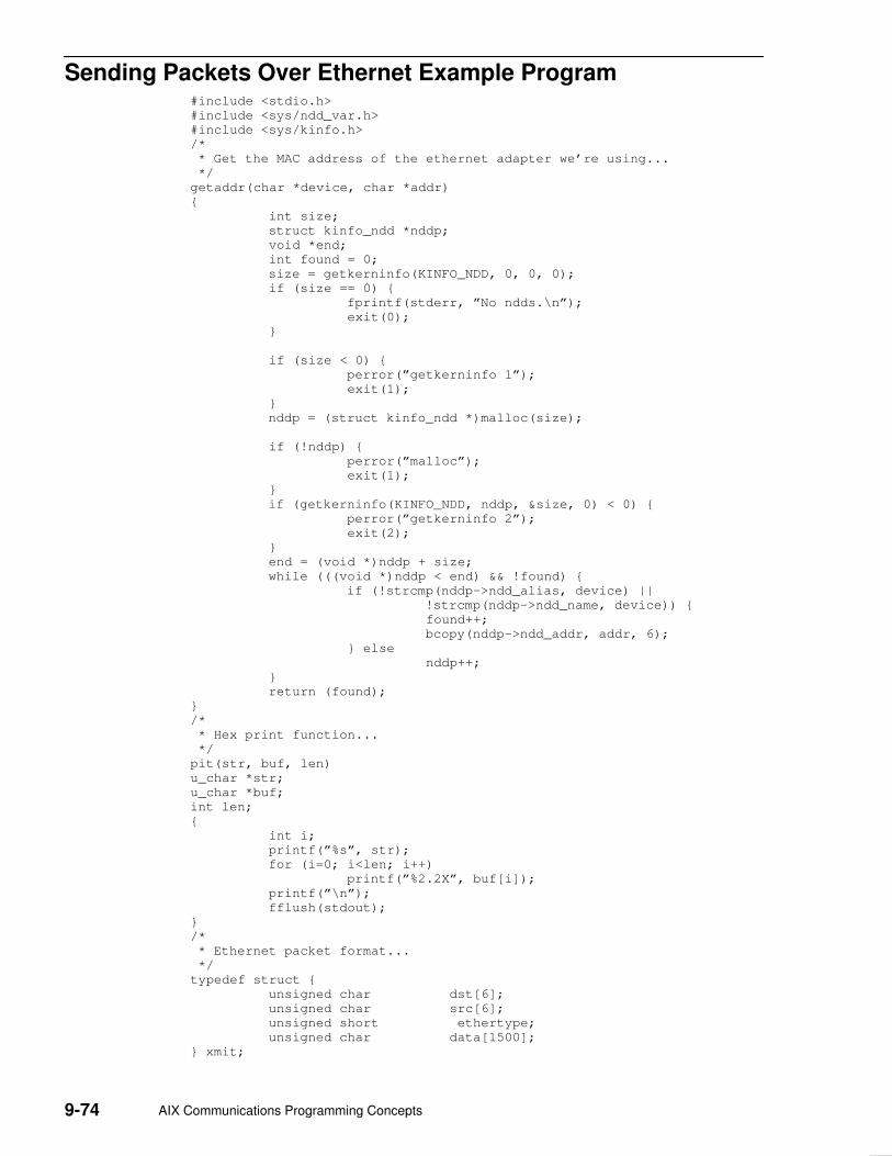
9-74 AIX Communications Programming Concepts
Sending Packets Over Ethernet Example Program #include <stdio.h>
#include <sys/ndd_var.h>
#include <sys/kinfo.h>
/*
* Get the MAC address of the ethernet adapter we’re using...
*/
getaddr(char *device, char *addr)
{
int size;
struct kinfo_ndd *nddp;
void *end;
int found = 0;
size = getkerninfo(KINFO_NDD, 0, 0, 0);
if (size == 0) {
fprintf(stderr, ”No ndds.\n”);
exit(0);
}
if (size < 0) {
perror(”getkerninfo 1”);
exit(1);
}
nddp = (struct kinfo_ndd *)malloc(size);
if (!nddp) {
perror(”malloc”);
exit(1);
}
if (getkerninfo(KINFO_NDD, nddp, &size, 0) < 0) {
perror(”getkerninfo 2”);
exit(2);
}
end = (void *)nddp + size;
while (((void *)nddp < end) && !found) {
if (!strcmp(nddp–>ndd_alias, device) ||
!strcmp(nddp–>ndd_name, device)) {
found++;
bcopy(nddp–>ndd_addr, addr, 6);
} else
nddp++;
}
return (found);
}
/*
* Hex print function...
*/
pit(str, buf, len)
u_char *str;
u_char *buf;
int len;
{
int i;
printf(”%s”, str);
for (i=0; i<len; i++)
printf(”%2.2X”, buf[i]);
printf(”\n”);
fflush(stdout);
}
/*
* Ethernet packet format...
*/
typedef struct {
unsigned char dst[6];
unsigned char src[6];
unsigned short ethertype;
unsigned char data[1500];
} xmit;

Sockets 9-75
/*
* Convert ascii hardware address into byte string.
*/
hwaddr_aton(a, n)
char *a;
u_char *n;
{
int i, o[6];
i = sscanf(a, ”%x:%x:%x:%x:%x:%x”, &o[0], &o[1], &o[2],
&o[3], &o[4], &o[5]);
if (i != 6) {
fprintf(stderr, ”invalid hardware address ’%s’\n”);
return (0);
}
for (i=0; i<6; i++)
n[i] = o[i];
return (6);
}
main(int argc, char *argv[]) {
char srcaddr[6];
char *device, dstaddr[6];
u_int ethertype;
u_int count, size;
xmit buf;
int s;
struct sockaddr_ndd_8022 sa;
int last;
if (argc != 6) {
printf(”Usage: %s <ifname> dstaddr ethertype count
size\n”, argv[0]);
printf(”EG: %s en0 01:02:03:04:05:06 0x600 10 10\n”,
argv[0]);
exit(1);
}
if (!getaddr(argv[1], srcaddr)) {
printf(”interface not found\n”);
exit(1);
}
device=argv[1];
hwaddr_aton(argv[2], dstaddr);
pit(”src addr = ”, srcaddr, 6);
pit(”dst addr = ”, dstaddr, 6);
sscanf(argv[3], ”%x”, ðertype);
count = atoi(argv[4]);
size = atoi(argv[5]);
if (size > 1500)
size = 1500;
if (size < 60)
size = 60;
printf(”Ethertype: %x\n”, ethertype);
printf(”Count: %d\n”, count);
printf(”Size: %d\n”, size);
s = socket(AF_NDD, SOCK_DGRAM, NDD_PROT_ETHER);
if (s < 0) {
perror(”socket”);
exit(1);
}
sa.sndd_8022_family = AF_NDD;
sa.sndd_8022_len = sizeof(sa);
sa.sndd_8022_filtertype = NS_ETHERTYPE;
sa.sndd_8022_ethertype = (u_short)ethertype;
sa.sndd_8022_filterlen = sizeof(struct ns_8022);
bcopy(device, sa.sndd_8022_nddname,
sizeof(sa.sndd_8022_nddname));
if (bind(s, (struct sockaddr *)&sa, sizeof(sa))) {
perror(”bind”);
exit(2);
}

9-76 AIX Communications Programming Concepts
bcopy(dstaddr, buf.dst, sizeof(buf.dst));
bcopy(srcaddr, buf.src, sizeof(buf.src));
buf.ethertype = (u_short)ethertype;
if (connect(s, (struct sockaddr *)&sa, sizeof(sa)) < 0) {
perror(”connect”);
exit(3);
}
last = count;
while (count–– > 0) {
sprintf(buf.data, ”Foo%d”, last–count);
if (write(s, &buf, size) < 0) {
perror(”write”);
exit(4);
}
}
close(s);
}

Sockets 9-77
Analyzing Packets Over the Network Example Program /*
* Simple sniffer to capture 802.2 frames on 802.3 ethernet, token ring,
* FDDI, and other CDLI devices that support 802.2 encapsulation...
*/
#include <stdio.h>
#include <sys/types.h>
#include <sys/ndd_var.h>
#include <sys/tok_demux.h>
#include <netinet/if_802_5.h>
main(argc, argv)
int argc;
char *argv[];
{
int s;
struct sockaddr_ndd_8022 sa;
struct sockaddr_ndd_8022 from;
struct sockaddr *fromp = (struct sockaddr *)&from;
int len;
char buf[2000];
int cc;
u_long fromlen;
int sap;
struct ie5_mac_hdr *macp = (struct ie5_mac_hdr *)buf;
struct ie2_llc_hdr *llcp;
if (argc != 3) {
printf(”Usage %s <interface> <sap>\n”, argv[0]);
exit(1);
}
sscanf(argv[2], ”%x”, &sap);
printf(”sap is %x\n”, sap);
s = socket(AF_NDD, SOCK_DGRAM, 0);
if (s < 0) {
perror(”socket”);
exit(1);
}
sa.sndd_8022_family = AF_NDD;
sa.sndd_8022_len = sizeof(struct sockaddr_ndd_8022);
sa.sndd_8022_filtertype = NS_TAP;
sa.sndd_8022_filterlen = sizeof(ns_8022_t);
strcpy(sa.sndd_8022_nddname, argv[1]);
if (bind(s, (struct sockaddr *)&sa, sizeof(struct
sockaddr_ndd_8022))) {
perror(”bind”);
exit(2);
}
len = sizeof(buf);
fromlen = sizeof(from);
while (TRUE) {
if ((cc = recvfrom(s, buf, len, 0, fromp, &fromlen))
< 0) {
perror(”recvfrom”);
exit(3);
}
if (!strcmp(argv[1], ”ent0”))
llcp = (struct ie2_llc_hdr *)(buf+14);
else
llcp = (struct ie2_llc_hdr *)(buf +
mac_size(macp));
if ((llcp–>dsap == sap) || (llcp–>ssap == sap))
printit(buf, cc);
}
}

9-78 AIX Communications Programming Concepts
printit(char *buf, int cc)
{
int i;
printf(”FRAME: ”);
for (i=0; i < cc; i++)
printf(”%2.2x”, *(buf+i));
printf(”\n”);
}

STREAMS 10-1
Chapter 10. STREAMS
STREAMS is a general, flexible facility and a set of tools for developing systemcommunication services. With STREAMS, developers can provide services ranging fromcomplete networking protocol suites to individual device drivers.
This chapter provides an overview of the major STREAMS concepts. Consult UNIX SystemV Release 4, Programmer’s Guide: STREAMS and Data Link Provider InterfaceSpecification for additional information.
The following concepts are discussed:
• STREAMS Introduction
• Benefits and Features of STREAMS, on page 10-7
• STREAMS Flow Control, on page 10-9
• STREAMS Synchronization, on page 10-11
• Using STREAMS, on page 10-18
• STREAMS Tunable Parameters, on page 10-19
• streamio STREAMS ioctl operations, on page 10-22
• Building STREAMS, on page 10-23
• STREAMS Messages, on page 10-25
• Put and Service Procedures, on page 10-29
• STREAMS Drivers and Modules, on page 10-31
• log Device Driver, on page 10-35
• Configuring Drivers and Modules in the Portable Streams Environment, on page 10-37.
• Asynchronous Protocol STREAMS Example, on page 10-40
• Differences Between Portable Streams Environment and V.4 STREAMS, on page 10-46
• List of Streams Commands, on page 10-48
• List of STREAMS Programming References, on page 10-49
• Transport Service Library Interface Overview, on page 10-52
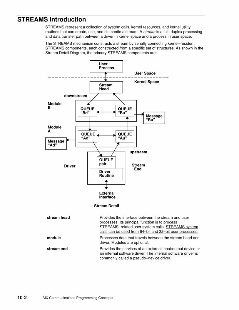
10-2 AIX Communications Programming Concepts
STREAMS Introduction STREAMS represent a collection of system calls, kernel resources, and kernel utilityroutines that can create, use, and dismantle a stream. A stream is a full–duplex processingand data transfer path between a driver in kernel space and a process in user space.
The STREAMS mechanism constructs a stream by serially connecting kernel–residentSTREAMS components, each constructed from a specific set of structures. As shown in theStream Detail Diagram, the primary STREAMS components are:
UserProcess
StreamHead
QUEUE“Bd”
QUEUE“Bu”
QUEUE“Ad”
QUEUE“Au”
DriverRoutine
QUEUEpair
Message“Bu”
Message“Ad”
ModuleA
ModuleB
downstream
upstream
Driver Stream End
ExternalInterface
Stream Detail
User Space
Kernel Space
stream head Provides the interface between the stream and userprocesses. Its principal function is to processSTREAMS–related user system calls. STREAMS systemcalls can be used from 64–bit and 32–bit user processes.
module Processes data that travels between the stream head anddriver. Modules are optional.
stream end Provides the services of an external input/output device oran internal software driver. The internal software driver iscommonly called a pseudo–device driver.

STREAMS 10-3
STREAMS defines standard interfaces for character input and output within the systemkernel and between the kernel and the rest of the system. The associated mechanism issimple and open–ended. It consists of a set of system calls, kernel resources, and kernelutility routines. The standard interface and open–ended mechanism enable modular,portable development and easy integration of high–performance network services andcomponents. STREAMS does not impose any specific network architecture. Instead, itprovides a powerful framework with a consistent user interface that is compatible with theexisting character input/output interface.
Using a combination of system calls, kernel routines, and kernel utilities, STREAMS passesdata between a driver and the stream head in the form of messages. Messages that arepassed from the stream head toward the driver are said to travel downstream whilemessages passed in the other direction travel upstream.
Stream Head The stream head transfers data between the data space of a user process and STREAMSkernel data space. Data sent to a driver from a user process is packaged into STREAMSmessages and transmitted downstream. Downstream messages arriving at the stream headare processed by the stream head, and data is copied from user buffers. STREAMS caninsert one or more modules into a stream between the stream head and the driver toprocess data passing between the two.
The stream head provides an interface between the stream and an application program.The stream head processes STREAMS–related operations from the application andperforms the bidirectional transfer of data and information between the application (in userspace) and messages (in STREAMS kernel space).
Messages are the only means of transferring data and communicating within a stream. ASTREAMS message contains data, status or control information, or a combination of both.Each message includes a specified message type indicator that identifies the contents.
See ”STREAMS Messages”, on page 10-25 for more information about the STREAMSmessage–passing scheme.

10-4 AIX Communications Programming Concepts
Modules A module performs intermediate transformations on messages passing between the streamhead and the driver. Zero or more modules can exist in a stream (zero when the driverperforms all the required character and device processing).
Each module is constructed from a pair of QUEUE structures (see the Au/Ad QUEUE pairand the Bu/Bd QUEUE pair in the Stream Detail diagram). A pair of such structures isrequired to implement the bidirectional and symmetrical attributes of a stream. One QUEUE(such as the Au or Bu QUEUE) performs functions on messages passing upstream throughthe module. The other QUEUE (the Ad or Bd QUEUE) performs another set of functions ondownstream messages. (A QUEUE, which is part of a module, is different from a messagequeue, which is described in ”STREAMS Flow Control”, on page 10-9.)
UserProcess
StreamHead
QUEUE“Bd”
QUEUE“Bu”
QUEUE“Ad”
QUEUE“Au”
DriverRoutine
QUEUEpair
Message“Bu”
Message“Ad”
ModuleA
ModuleB
downstream
upstream
Driver Stream End
ExternalInterface
Stream Detail
User Space
Kernel Space
Each of the two QUEUEs in a module generally have distinct functions; that is, unrelatedprocessing procedures and data. The QUEUEs operate independently so that the AuQUEUE does not know if a message passes though the Ad QUEUE unless the Ad QUEUEis programmed to inform it. Messages and data can be shared only if the developerspecifically programs the module functions to perform the sharing.
Each QUEUE can directly access the adjacent QUEUE in the direction of message flow (forexample, Au to Bu or stream head to Bd). In addition, within a module, a QUEUE canreadily locate its mate and access its messages (for example, for echoing) and data.
Each QUEUE in a module can contain or point to:
• Messages –– These are dynamically attached to the QUEUE on a linked list, or messagequeue (see Ad and Bu in the Stream Detail diagram), as they pass through the module.

STREAMS 10-5
UserProcess
StreamHead
QUEUE“Bd”
QUEUE“Bu”
QUEUE“Ad”
QUEUE“Au”
DriverRoutine
QUEUEpair
Message“Bu”
Message“Ad”
ModuleA
ModuleB
downstream
upstream
Driver Stream End
ExternalInterface
Stream Detail
User Space
Kernel Space
• Processing procedures –– A put procedure must be incorporated in each QUEUE toprocess messages. An optional service procedure for sharing the message processingwith the put procedure can also be incorporated. According to their function, theprocedures can send messages upstream or downstream, and they can also modify theprivate data in their module.
See ”Put and Service Procedures”, on page 10-29 for more information about processingprocedures.
• Data –– Developers can provide private data if required by the QUEUE to performmessage processing (for example, state information and translation tables).
In general, each of the two QUEUEs in a module has a distinct set of all these elements.Additional module elements are described later. Although depicted as distinct from modules,a stream head and a stream end also contain a pair of QUEUEs.
Stream End A stream end is a module in which the module processing procedures are the driverroutines. The procedures in the stream end are different from those in other modulesbecause they are accessible from an external device and because the STREAMSmechanism allows multiple streams to be connected to the same driver.
The driver can be a device driver, providing an interface between kernel space and anexternal communications device, or an internal pseudo–device driver. A pseudo–devicedriver is not directly related to any external device, and it performs functions internal to thekernel.

10-6 AIX Communications Programming Concepts
Device drivers must transform all data and status or control information between STREAMSmessage formats and their external representation. See ”STREAMS Drivers and Modules”,on page 10-31 for more information on the differences between STREAMS and characterdevice drivers.
STREAMS ModularitySTREAMS modularity and design reflect the layers and option characteristics ofcontemporary networking architectures. The basic components in a STREAMSimplementation are referred to as modules. The modules, which reside in the kernel, offer aset of processing functions and associated service interfaces. From a user level, modulescan be selected dynamically and interconnected to provide any rational processingsequence. Kernel programming, assembly, and link editing are not required to create theinterconnection. Modules can also be dynamically plugged into existing connections fromuser level. STREAMS modularity allows:
• User–level programs that are independent of underlying protocols and physicalcommunication media
• Network architectures and high–level protocols that are independent of underlyingprotocols, drivers, and physical communication media
• High–level services that can be created by selecting and connecting low–level servicesand protocols
• Enhanced portability of protocol modules, resulting from the well–defined structure andinterface standards of STREAMS.
STREAMS FacilitiesIn addition to modularity, STREAMS provides developers with integral functions, a library ofutility routines, and facilities that expedite software design and implementation. The principalfacilities are:
Buffer management Maintains an independent buffer pool for STREAMS.
Scheduling Incorporates a scheduling mechanism for STREAMS.
Asynchronous operation of STREAMS and user processes
Allows STREAMS–related operations to be performedefficiently from user level.
Other facilities include flow control to conserve STREAMS memory and processingresources.

STREAMS 10-7
Benefits and Features of STREAMSSTREAMS offers two major benefits for applications programmers:
• Easy creation of modules that offer standard data communications services
• The ability to manipulate those modules on a stream.
Additional STREAMS features are provided to handle characteristic problems of protocolimplementation and to assist in development. There are also kernel– and user–levelfacilities that support the implementation of advanced functions and allow asynchronousoperation of a user process and STREAMS input and output. The following features arediscussed:
• Flow control, on page 10-9
• Synchronization, on page 10-11
Creating Service InterfacesOne benefit of STREAMS is that it simplifies the creation of modules that present a serviceinterface to any neighboring application program, module, or device driver. A serviceinterface is defined at the boundary between two neighbors. In STREAMS, a serviceinterface is a specified set of messages and the rules for allowable sequences of thesemessages across the boundary. A module that implements a service interface will receive amessage from a neighbor and respond with an appropriate action (for example, send back arequest to retransmit) based on the specific message received and the preceding sequenceof messages.
STREAMS provides features that make it easier to design various application processesand modules to common service interfaces. If these modules are written to comply withindustry–standard service interfaces, they are called protocol modules.
In general, any two modules can be connected anywhere in a stream. However, rationalsequences are generally constructed by connecting modules with compatible protocolservice interfaces.
Manipulating ModulesSTREAMS provides the capabilities to manipulate modules from user level, to interchangemodules with common service interfaces, and to present a service interface to a streamuser process. These capabilities yield benefits when implementing networking services andprotocols, including:
• User–level programs can be independent of underlying protocols and physicalcommunication media.
• Network architectures and high–level protocols can be independent of underlyingprotocols, drivers, and physical communication media.
• Higher–level services can be created by selecting and connecting lower–level servicesand protocols.
Examples of the benefits of STREAMS capabilities to developers for creating serviceinterfaces and manipulating modules are:
• Protocol substitution
• Module reusability

10-8 AIX Communications Programming Concepts
Protocol Substitution Alternative protocol modules (and device drivers) can be interchanged on the samemachine if they are implemented to equivalent service interfaces.
Module Reusability The Module Reusability Diagram shows the same canonical module (for example, one thatprovides delete and kill processing on character strings) reused in two different streams.This module typically is implemented as a filter, with no downstream service interface. Inboth cases, a tty interface is presented to the stream user process since the module isnearest the stream head.
Class 1TransportProtocol
SAMEINTERFACE
UserProcess
CanonicalModule
LAPBDriver
UserProcess
CanonicalModule
SAMEModule
RawTTYDriver
Module Reusability
STREAMS 10-9
STREAMS Flow Control Even on a well–designed system, general system delays, malfunctions, and excessiveaccumulation on one or more streams can cause the message buffer pools to becomedepleted. Additionally, processing bursts can arise when a service procedure in one modulehas a long message queue and processes all its messages in one pass. STREAMSprovides an independent mechanism to guard its message buffer pools from being depletedand to minimize long processing bursts at any one module.
Note: Flow control is applied only to normal priority messages.
The flow control mechanism is local to each stream and is advisory (voluntary), and it limitsthe number of characters that can be queued for processing at any QUEUE in a stream.This mechanism limits the buffers and related processing at any one QUEUE and in anyone stream, but does not consider buffer pool levels or buffer usage in other streams.
The advisory mechanism operates between the two nearest QUEUEs in a streamcontaining service procedures. Messages are generally held on a message queue only if aservice procedure is present in the associated QUEUE.
Messages accumulate at a QUEUE when its service procedure processing does not keeppace with the message arrival rate, or when the procedure is blocked from placing itsmessages on the following stream component by the flow–control mechanism. Pushablemodules contain independent upstream and downstream limits, which are set when adeveloper specifies high–water and low–water control values for the QUEUE. The streamhead contains a preset upstream limit (which can be modified by a special message sentfrom downstream) and a driver may contain a downstream limit.
STREAMS flow control operates in the following order:
1. Each time a STREAMS message–handling routine (for example, the putq utility) adds orremoves a message from a message queue in a QUEUE, the limits are checked.STREAMS calculates the total size of all message blocks on the message queue.
2. The total is compared to the QUEUE high–water and low–water values. If the totalexceeds the high–water value, an internal full indicator is set for the QUEUE. Theoperation of the service procedure in this QUEUE is not affected if the indicator is set,and the service procedure continues to be scheduled.
3. The next part of flow control processing occurs in the nearest preceding QUEUE thatcontains a service procedure. In the the Flow Control Diagram, if D is full and C has noservice procedure, then B is the nearest preceding QUEUE.
4. In the Flow Control Diagram, the service procedure in B uses a STREAMS utility routineto see if a QUEUE ahead is marked full. If messages cannot be sent, the schedulerblocks the service procedure in B from further execution. B remains blocked until thelow–water mark of the full QUEUE D is reached.
5. While B is blocked (in the Flow Control Diagram), any nonpriority messages that arrive atB will accumulate on its message queue (recall that priority messages are not blocked).In turn, B can reach a full state and the full condition will propagate back to the lastmodule in the stream.
6. When the service procedure processing on D (in the Flow Control Diagram) causes themessage block total to fall below the low–water mark, the full indicator is turned off.Then, STREAMS automatically schedules the nearest preceding blocked QUEUE (in thiscase, B) and gets things moving again. This automatic scheduling is known asback–enabling a QUEUE.
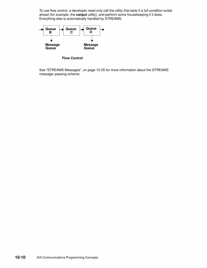
10-10 AIX Communications Programming Concepts
To use flow control, a developer need only call the utility that tests if a full condition existsahead (for example, the canput utility), and perform some housekeeping if it does.Everything else is automatically handled by STREAMS.
Queue B
Queue C
Queue D
MessageQueue
MessageQueue
Flow Control
See ”STREAMS Messages”, on page 10-25 for more information about the STREAMSmessage–passing scheme.

STREAMS 10-11
STREAMS Synchronization In a multi–threaded environment, several threads may access the same stream, the samemodule, or even the same queue at the same time. In order to protect the STREAMSresources (queues and other specific data), STREAMS provides per–thread resourcesynchronization. This synchronization is ensured by STREAMS and is completelytransparent to the user.
Read the following to learn more about STREAMS synchronization:
• Synchronization Mechanism
• Synchronization of timeout and bufcall Utilities
• Synchronization Levels
• Per–stream Synchronization
• Queue–Welding Mechanism
Synchronization MechanismSTREAMS uses a synchronization–queueing mechanism that maximizes executionthroughput. A synchronization queue is a linked list of structures. Each structureencapsulates a callback to a function attempting to access a resource. A thread whichcannot block (a service procedure, for example) can access the resource using atransparent call.
• If the resource is already held by another thread, the thread puts a request on theresource’s synchronization queue.
• If the resource is free, the thread executes its request immediately. After having done itsjob, and before releasing the resource, the thread goes through the synchronizationqueue and executes all the pending requests.
In either case, the call returns immediately. Routines performing synchronous operations,like stream head routines, are blocked until they gain access to the resource. Although themechanism is completely transparent, the user needs to set the adequate synchronizationlevel.
Synchronization of timeout and bufcall UtilitiesOn multiprocessor systems, the timeout and bufcall utilities present a particular problem tothe synchronization mechanism. These utilities specify a callback function.Multiprocessor–safe modules or drivers require that the callback functions be interrupt–safe.
Multiprocessor–safe modules or drivers are designed to run on any processor. They arevery similar to multiprocessor–safe device drivers. Interrupt–safe functions serialize theircode with interrupt handlers. Functions such as the qenable utility or the wakeup kernelservice are interrupt–safe.
To support callback functions that are not interrupt–safe, the STR_QSAFETY flag can beset when calling the str_install utility. When this flag is set, STREAMS ensures the dataintegrity of the module. Using this flag imposes an overhead to the module or driver, thus itshould only be used when porting old code. When writing new code, callback functions mustbe interrupt–safe.
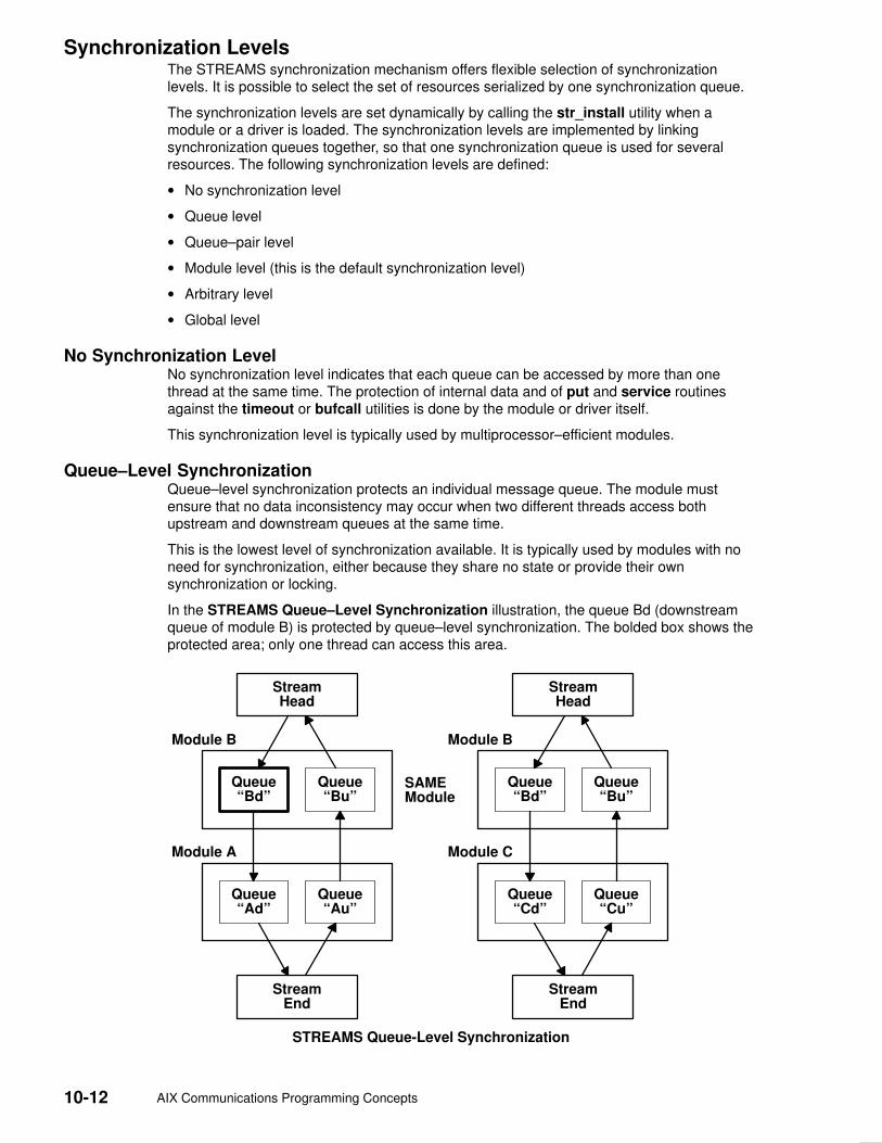
10-12 AIX Communications Programming Concepts
Synchronization LevelsThe STREAMS synchronization mechanism offers flexible selection of synchronizationlevels. It is possible to select the set of resources serialized by one synchronization queue.
The synchronization levels are set dynamically by calling the str_install utility when amodule or a driver is loaded. The synchronization levels are implemented by linkingsynchronization queues together, so that one synchronization queue is used for severalresources. The following synchronization levels are defined:
• No synchronization level
• Queue level
• Queue–pair level
• Module level (this is the default synchronization level)
• Arbitrary level
• Global level
No Synchronization LevelNo synchronization level indicates that each queue can be accessed by more than onethread at the same time. The protection of internal data and of put and service routinesagainst the timeout or bufcall utilities is done by the module or driver itself.
This synchronization level is typically used by multiprocessor–efficient modules.
Queue–Level SynchronizationQueue–level synchronization protects an individual message queue. The module mustensure that no data inconsistency may occur when two different threads access bothupstream and downstream queues at the same time.
This is the lowest level of synchronization available. It is typically used by modules with noneed for synchronization, either because they share no state or provide their ownsynchronization or locking.
In the STREAMS Queue–Level Synchronization illustration, the queue Bd (downstreamqueue of module B) is protected by queue–level synchronization. The bolded box shows theprotected area; only one thread can access this area.
StreamHead
Queue“Bd”
Queue“Bu”
Queue“Ad”
Queue“Au”
Module A
Module B
StreamEnd
StreamHead
Queue“Bd”
Queue“Bu”
Queue“Cd”
Queue“Cu”
Module C
Module B
StreamEnd
SAMEModule
STREAMS Queue-Level Synchronization

STREAMS 10-13
Queue Pair–Level SynchronizationQueue pair–level synchronization protects the pair of message queues (downstream andupstream) of one instance of a module. The module may share common data between bothqueues, but it cannot assume that two instances of the module are accessed by twodifferent threads at the same time.
Queue pair–level synchronization is a common synchronization level for most modules thathave only per–stream data, such as TTY line disciplines. All stream–head queues aresynchronized at this level.
In the Queue Pair–Level Synchronization illustration, the queue pair of module B’s leftinstance is protected by queue pair–level synchronization. The boxes highlighted in boldshow the protected area; only one thread can access this area.
StreamHead
Queue“Bd”
Queue“Bu”
Queue“Ad”
Queue“Au”
Module A
Module B
StreamEnd
StreamHead
Queue“Bd”
Queue“Bu”
Queue“Cd”
Queue“Cu”
Module C
Module B
StreamEnd
SAMEModule
Queue Pair-Level Synchronization
Module–Level SynchronizationModule–level synchronization protects all instances of one module or driver. The module (ordriver) can have global data, shared among all instances of the module. This data and allmessage queues are protected against concurrent access.
Module–level synchronization is the default synchronization level. Modules protected at thislevel are not required to be thread–safe, since multiple threads cannot access the module.Module–level synchronization is also used by modules that maintain shared stateinformation.
In the Module–Level Synchronization illustration, module B (both instances) is protectedby module–level synchronization. The boxes highlighted in bold show the protected area;only one thread can access this area.

10-14 AIX Communications Programming Concepts
StreamHead
Queue“Bd”
Queue“Bu”
Queue“Ad”
Queue“Au”
Module A
Module B
StreamEnd
StreamHead
Queue“Bd”
Queue“Bu”
Queue“Cd”
Queue“Cu”
Module C
Module B
StreamEnd
SAMEModule
Module-Level Synchronization
Arbitrary–Level SynchronizationArbitrary–level synchronization protects an arbitrary group of modules or drivers (includingall instances of each module or driver). A name passed when setting this level (with thestr_install utility) is used to associate modules together. The name is decided byconvention among cooperating modules.
Arbitrary–level synchronization is used for synchronizing a group of modules that accesseach other’s data. An example might be a networking stack such as a Transmission ControlProtocol (TCP) module and an Internet Protocol (IP) module, both of which share data.Such modules might agree to pass the string ”tcp/ip”.
In the Arbitrary–Level Synchronization illustration, modules A and B are protected byarbitrary–level synchronization. Module A and both instances of module B are in the samegroup. The boxes highlighted in bold show the protected area; only one thread can accessthis area.

STREAMS 10-15
StreamHead
Queue“Bd”
Queue“Bu”
Queue“Ad”
Queue“Au”
Module A
Module B
StreamEnd
StreamHead
Queue“Bd”
Queue“Bu”
Queue“Cd”
Queue“Cu”
Module C
Module B
StreamEnd
SAMEModule
Arbitrary-Level Synchronization
Global–Level SynchronizationGlobal–level synchronization protects the entire STREAMS.
Note: This level can be useful for debugging purposes, but should not be used otherwise.
Per–stream SynchronizationSynchronization levels take all their signification in multiprocessor systems. In auniprocessor system, the benefit of synchronization is reduced; and sometimes it is better toprovide serialization rather than concurrent execution. The per–stream synchronizationprovides this serialization on a whole stream and can be applied only if the whole streamaccepts to run on this mode. Two conditions are required for a module or driver to run atper–stream–synchronization level:
• The STR_PERSTREAM flag must be set when calling the str_install utility.
• Either the queue level or the queue pair–level synchronization must be set when callingthe str_install utility.
If a module that does not support the per–stream synchronization is pushed in the stream,then all other modules and drivers will be reset to their original synchronization level (queuelevel or the queue–pair level).
In the same way, if a module that was not supporting the per–stream synchronization ispopped out of the stream, a new check of the stream is done to see if it now deals with aper–stream synchronization.
Queue–Welding Mechanism The STREAMS synchronization–queueing mechanism allows only one queue to beaccessed at any one time. In some cases, however, it is necessary for a thread to establishqueue connections between modules that are not in the same stream.
These queue connections (welding mechanism) are especially useful for STREAMSmultiplexing and for echo–like STREAMS drivers.

10-16 AIX Communications Programming Concepts
Welding QueuesSTREAMS uses a special synchronization queue for welding queues. As for individualqueue synchronization, the welding and unwelding requests are queued. The actualoperation is done safely by STREAMS, without any risk of deadlocks.
The weldq and unweldq utilities, respectively, establish and remove connections betweenone or two pairs of module or driver queues. Since the actual operation is doneasynchronously, the utilities specify a callback function and its argument. The callbackfunction is typically the qenable utility or the e_wakeup kernel service.
During the welding or unwelding operation, both pairs of queues are acquired, as shown inthe STREAMS Queue–Welding Synchronization illustration. However, it may benecessary to prevent another queue, queue pair, module, or group of modules from beingaccessed during the operation. Therefore, an additional queue can be specified whencalling the weldq or unweldq utility; this queue will also be acquired during the operation.Depending on the synchronization level of the module to which this queue belongs, thequeue, the queue pair, the module instance, all module instances, or an arbitrary group ofmodules will be acquired.
StreamHead
Queue“Bd”
Queue“Bu”
Queue“Ad”
Queue“Au”
Module A
Module B
StreamHead
Queue“Dd”
Queue“Du”
Queue“Cd”
Queue“Cu”
Module C
Module D

STREAMS 10-17
For example, in the Queue Welding Using an Extra Queue illustration, the welding is doneusing the queue Bd as an extra synchronization queue. Module B is synchronized at modulelevel. Therefore, the queues Ad, Au, Cd, and Cu and all instances of module B will all beacquired for performing the weld operation.
StreamHead
Queue“Bd”
Queue“Bu”
Queue“Ad”
Queue“Au”
Module A
Module B
StreamHead
Queue“Dd”
Queue“Du”
Queue“Cd”
Queue“Cu”
Module C
Module D
Queue Welding Using an Extra Queue

10-18 AIX Communications Programming Concepts
Using STREAMSApplications programmers can take advantage of the STREAMS facilities by using a set ofsystem calls, subroutines, utilities, and operations. The subroutine interface isupward–compatible with the existing character I/O facilities.
SubroutinesThe open, close, read, and write subroutines support the basic set of operations onstreams. In addition, new operations support advanced STREAMS facilities.
The poll subroutine enables an application program to poll multiple streams for variousevents. When used with the I_SETSIG operation, the poll subroutine allows an applicationto process I/O in an asynchronous manner.
The following is a set of STREAMS–related subroutines:
open Opens a stream to the specified driver.
close Closes a stream.
read Reads data from a stream. Data is read in the same manner ascharacter files and devices.
write Writes data to a stream. Data is written in the same manner ascharacter files and devices.
poll Notifies the application program when selected events occur on astream.
System CallsThe putmsg and getmsg system calls enable application programs to interact withSTREAMS modules and drivers through a service interface.
getmsg Receives the message at the stream head.
getpmsg Receives the priority message at the stream head.
putmsg Sends a message downstream.
putpmsg Sends a priority message downstream.
streamio OperationsAfter a stream has been opened, ioctl operations allow a user process to insert and delete(push and pop) modules. That process can then communicate with and control theoperation of the stream head, modules, and drivers, and can send and receive messagescontaining data and control information.
ioctl Controls a stream by enabling application programs to performfunctions specific to a particular device. A set of generic STREAMS ioctloperations (referred to as streamio operations) support a variety offunctions for accessing and controlling streams.

STREAMS 10-19
STREAMS Tunable Parameters Certain system parameters referenced by STREAMS are configurable during system bootor while the system is running. These parameters are tunable based on requirements.There are two types of STREAMS tunable parameters: load–time configurable and run–timeconfigurable parameters. At boot time, the strload command loads the STREAMSframework in the AIX kernel. This command is used to set both types of parameters using aconfiguration file. To configure the run–time parameters, use the no command. The nocommand also displays all the parameter values.
Load–Time ParametersThe load–time parameters can only be set at initial STREAMS load time. The strloadcommand reads the parameter names and values from the /etc/pse_tune.conf file. This filecan be modified by privileged users only. It contains parameter names and values in thefollowing format:
# Streams Tunable Parameters
#
# This file contains Streams tunable parameter values.
# The initial values are the same as the default values.
# To change any parameter, modify the parameter value and
# the next system reboot will make it effective.
# To change the run–time parameter, use the no command any time.
strmsgsz 0 # run–time parameter
strctlsz 1024 # run–time parameter
nstrpush 8 # load–time parameter
psetimers 20 # run–time parameter
psebufcalls 20 # run–time parameter
strturncnt 15 # run–time parameter
strthresh 85 # run–time parameter, 85% of ”thewall”
lowthresh 90 # tun–time parameter, 90% of ”thewall”
medthresh 95 # run–time parameter, 95% of ”thewall”
pseintrstack 12288 # load–time parameter, (3 * 4096)
The initial values are the same as the default values. If the user changes any values, theyare effective on the next system reboot. If this file is not present in the system or if it isempty, the strload command will not fail, and all the parameters are set to their defaultvalues.
The load–time parameters are as follows:
nstrpush Indicates the maximum number of modules that can be pushed onto asingle STREAM. The default value is 8.
psetintrstack Indicates the maximum number of the interrupt stack size allowed bySTREAMS while running in the offlevel. Sometimes, when a process,running other than INTBASE level, enters a STREAM, it encountersstack overflow problems because of not enough interrupt stack size.Tuning this parameter properly reduces the chances of stack overflowproblems. The default value is 0x3000 (decimal 12288).

10-20 AIX Communications Programming Concepts
Run–Time ParametersThese parameters can be set using the no –o command or the no –d command, and theybecome effective immediately. If a user tries to set a load–time parameter to its default valueor to a new value using the no command, it returns an error. The no –a Parameter and no–o Parameter commands show the parameter’s current value.
The run–time parameters are as follows:
strmsgsz Specifies the maximum number of bytes that a single system call canpass to a STREAM to be placed into the data part of a message (inM_DATA blocks). Any write subroutine exceeding this size will bebroken into multiple messages. A putmsg subroutine with a data partexceeding this size will fail returning an ERANGE error code. Thedefault value is 0.
strctlsz Specifies the maximum number of bytes that a single system call canpass to a STREAM to be placed into the control part of a message (inan M_PROTO or M_PCPROTO block). A putmsg subroutine with acontrol part exceeding this size will fail returning an ERANGE errorcode. The default value is 1024.
strthresh Specifies the maximum number of bytes STREAMS are allowed toallocate. When the threshold is passed, users without the appropriateprivilege will not be allowed to open STREAMS, push modules, or writeto STREAMS devices. The ENOSR error code is returned. Thethreshold applies only to the output side; therefore, data coming intothe system is not affected and continues to work properly. A value of 0indicates there is no threshold.
The strthresh parameter represents a percentage of the value of thethewall parameter, and its value can be set between 0 and 100,inclusively. The thewall parameter indicates the maximum number ofbytes that can be allocated by STREAMS and sockets using thenet_malloc subroutine. The user can change the value of the thewallparameter using the no command. When the user changes the value ofthe thewall parameter, the threshold gets updated accordingly. Thedefault value is 85, indicating the threshold is 85% of the value of thethewall parameter.
psetimers Specifies the maximum number of timers allocated. In AIX, theSTREAM subsystem allocates a certain number of timer structures atinitialization time, so the STREAMS driver or module can register thetimeout requests. Lowering this value is not allowed until the systemreboots, at which time it returns to its default value. The default value is20.
psebufcalls Specifies the maximum number of bufcalls allocated. In AIX, theSTREAM subsystem allocates a certain number of bufcall structures atinitialization time. When an allocb subroutine fails, the user canregister requests for the bufcall subroutine. Lowering this value is notallowed until the system reboots, at which time it returns to its defaultvalue. The default value is 20.
STREAMS 10-21
strturncnt Specifies the maximum number of requests handled by the currentlyrunning thread for module– or elsewhere–level STREAMSsynchronization. The module–level synchronization works in such away that only one thread can run in the module at any given time, andall other threads trying to acquire the same module enqueue theirrequests and exit. After the currently running thread completes its work,it dequeues all the previously enqueued requests one at a time andstarts them. If there are large numbers of requests enqueued in the list,the currently running thread must serve everyone. To eliminate thisproblem, the currently running thread serves only the strturncnt numberof threads. After that, a separate kernel thread starts all the pendingrequests. The default value is 15.
lowthresh Specifies the maximum number of bytes (in percentage) allocated bythe thewall parameter using allocb for the BPRI_LO priority. When thetotal amount of memory allocated by the net_malloc subroutinereaches this threshold, the allocb request for the BPRI_LO priorityreturns 0. The lowthresh parameter can be set to any value between 0and 100, inclusively. The default value is 90, indicating the threshold isat 90% of the value of the thewall parameter.
medthresh Specifies the maximum number of bytes (in percentage) allocated bythe thewall parameter using allocb for the BPRI_MED priority. Whenthe total amount of memory allocated by the net_malloc subroutinereaches this threshold, the allocb request for the BPRI_MED priorityreturns 0. The medthresh parameter can be set to any value between 0and 100, inclusively. The default value is 95, indicating the threshold is95% of the value of the thewall parameter.

10-22 AIX Communications Programming Concepts
streamio (STREAMS ioctl) Operations The streamio operations are a subset of ioctl operations that perform a variety of controlfunctions on streams.
Because these STREAMS operations are a subset of the ioctl operations, they are subjectto the errors described there. In addition to those errors, the call fails with the errno globalvariable set to EINVAL, without processing a control function, if the specified stream islinked below a multiplexor, or if the specified operation is not valid for a stream.
Also, as described in the ioctl operations, STREAMS modules and drivers can detect errors.In this case, the module or driver sends an error message to the stream head containing anerror value. This causes subsequent system calls to fail with the errno global variable set tothis value.

STREAMS 10-23
Building STREAMS A stream is created on the first open subroutine to a character special file corresponding toa STREAMS driver.
A stream is usually built in two steps. Step one creates a minimal stream consisting of justthe stream head and device driver, and step two adds modules to produce an expandedstream as shown in the Stream Set Up diagram. Modules which can be added to a streamare known as pushable modules.
The first step in building a stream has three parts:
1. Allocate and initialize head and driver structures.
2. Link the modules in the head and end to each other to form a stream.
3. Call the driver open routine.
If the driver performs all character and device processing required, no modules need to beadded to a stream. Examples of STREAMS drivers include a raw tty driver (one that passesalong input characters without change) and a driver with multiple streams open to it(corresponding to multiple minor devices opened to a character device driver).
When the driver receives characters from the device, it places them into messages. Themessages are then transferred to the next stream component, the stream head, whichextracts the contents of the message and copies them to user space. Similar processingoccurs for downstream character output; the stream head copies data from user space intomessages and sends them to the driver.
Expanded StreamsAs the second step in building a stream, modules can be added to the stream. In theright–hand stream in the Stream Setup diagram, the CANONPROC module was added toprovide additional processing on the characters sent between head and driver.
Modules are added and removed from a stream in last–in–first–out (LIFO) order. They areinserted and deleted at the stream head by using ioctl operations. In the stream on the leftof the Module Reusability diagram, the Class 1 Transport was added first, followed by theCanonical modules. To replace the Class 1 module with a Class 0 module, the Canonicalmodule would have to be removed first, and then the Class 1 module. Finally a Class 0module would be added and the Canonical module put back.
Because adding and removing modules resembles stack operations, an add routine iscalled a push and the remove routine is called a pop. I_PUSH and I_POP are two of theoperations included in the STREAMS subset of ioctl operations (the streamio operations).These operations perform various manipulations of streams. The modules manipulated inthis manner are called pushable modules, in contrast to the modules contained in thestream head and stream end. This stack terminology applies only to the setup, modification,and breakdown of a stream.
Note: Subsequent use of the word module will refer to those pushable modules betweenstream head and stream end.
The stream head processes the streamio operation and executes the push, which isanalogous to opening the stream driver. Modules are referenced by a unique symbolicname, contained in the STREAMS fmodsw module table (similar to the devsw tableassociated with a device file). The module table and module name are internal to STREAMSand are accessible from user space only through STREAMS ioctl subroutines. Thefmodsw table points to the module template in the kernel. When a module is pushed, thetemplate is located, the module structures for both QUEUES are allocated, and the templatevalues are copied into the structures.
In addition to the module elements, each module contains pointers to an open routine and aclose routine. The open routine is called when the module is pushed, and the close routine
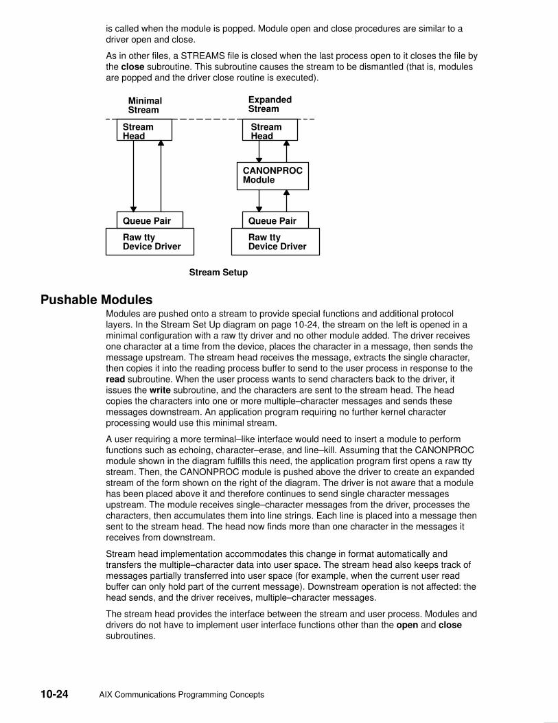
10-24 AIX Communications Programming Concepts
is called when the module is popped. Module open and close procedures are similar to adriver open and close.
As in other files, a STREAMS file is closed when the last process open to it closes the file bythe close subroutine. This subroutine causes the stream to be dismantled (that is, modulesare popped and the driver close routine is executed).
MinimalStream
ExpandedStream
StreamHead
CANONPROCModule
Queue Pair
Raw ttyDevice Driver
Queue Pair
Raw ttyDevice Driver
StreamHead
Stream Setup
Pushable ModulesModules are pushed onto a stream to provide special functions and additional protocollayers. In the Stream Set Up diagram on page 10-24, the stream on the left is opened in aminimal configuration with a raw tty driver and no other module added. The driver receivesone character at a time from the device, places the character in a message, then sends themessage upstream. The stream head receives the message, extracts the single character,then copies it into the reading process buffer to send to the user process in response to theread subroutine. When the user process wants to send characters back to the driver, itissues the write subroutine, and the characters are sent to the stream head. The headcopies the characters into one or more multiple–character messages and sends thesemessages downstream. An application program requiring no further kernel characterprocessing would use this minimal stream.
A user requiring a more terminal–like interface would need to insert a module to performfunctions such as echoing, character–erase, and line–kill. Assuming that the CANONPROCmodule shown in the diagram fulfills this need, the application program first opens a raw ttystream. Then, the CANONPROC module is pushed above the driver to create an expandedstream of the form shown on the right of the diagram. The driver is not aware that a modulehas been placed above it and therefore continues to send single character messagesupstream. The module receives single–character messages from the driver, processes thecharacters, then accumulates them into line strings. Each line is placed into a message thensent to the stream head. The head now finds more than one character in the messages itreceives from downstream.
Stream head implementation accommodates this change in format automatically andtransfers the multiple–character data into user space. The stream head also keeps track ofmessages partially transferred into user space (for example, when the current user readbuffer can only hold part of the current message). Downstream operation is not affected: thehead sends, and the driver receives, multiple–character messages.
The stream head provides the interface between the stream and user process. Modules anddrivers do not have to implement user interface functions other than the open and closesubroutines.

STREAMS 10-25
STREAMS Messages STREAMS provides a basic message–passing scheme based on the following concepts:
• Message blocks, on page 10-25
• Message allocation, on page 10-26
• Message types, on page 10-26
• Message queue priority, on page 10-27
• Sending and receiving messages, on page 10-28
• Put procedures, on page 10-29
• Service procedures, on page 10-29
Message BlocksA STREAMS message consists of one or more linked message blocks. That is, the firstmessage block of a message may be attached to other message blocks that are part of thesame message. Multiple blocks in a message can occur, for example, as the result ofprocessing that adds header or trailer data to the data contained in the message, orbecause of size limitations in the message buffer that cause the data to span multipleblocks. When a message is composed of multiple message blocks, the message type of thefirst block determines the type of the entire message, regardless of the types of the attachedmessage blocks.
STREAMS allocates a message as a single block containing a buffer of a certain size. If thedata for a message exceeds the size of the buffer containing the data, the procedure canallocate a new block containing a larger buffer, copy the current data to it, insert the newdata, and deallocate the old block. Alternatively, the procedure can allocate an additional(smaller) block, place the new data in the new message block, and link it after or before theinitial message block. Both alternatives yield one new message.
Messages can exist standalone when the message is being processed by a procedure.Alternatively, a message can await processing on a linked list of messages, called amessage queue, in a QUEUE. In the Message Queue diagram on page 10-26, Message 1is linked to Message 2.
When a message is queued, the first block of the message contains links to preceding andsucceeding messages on the same message queue, in addition to containing a link to thesecond block of the message (if present). The message queue head and tail are containedin the QUEUE.
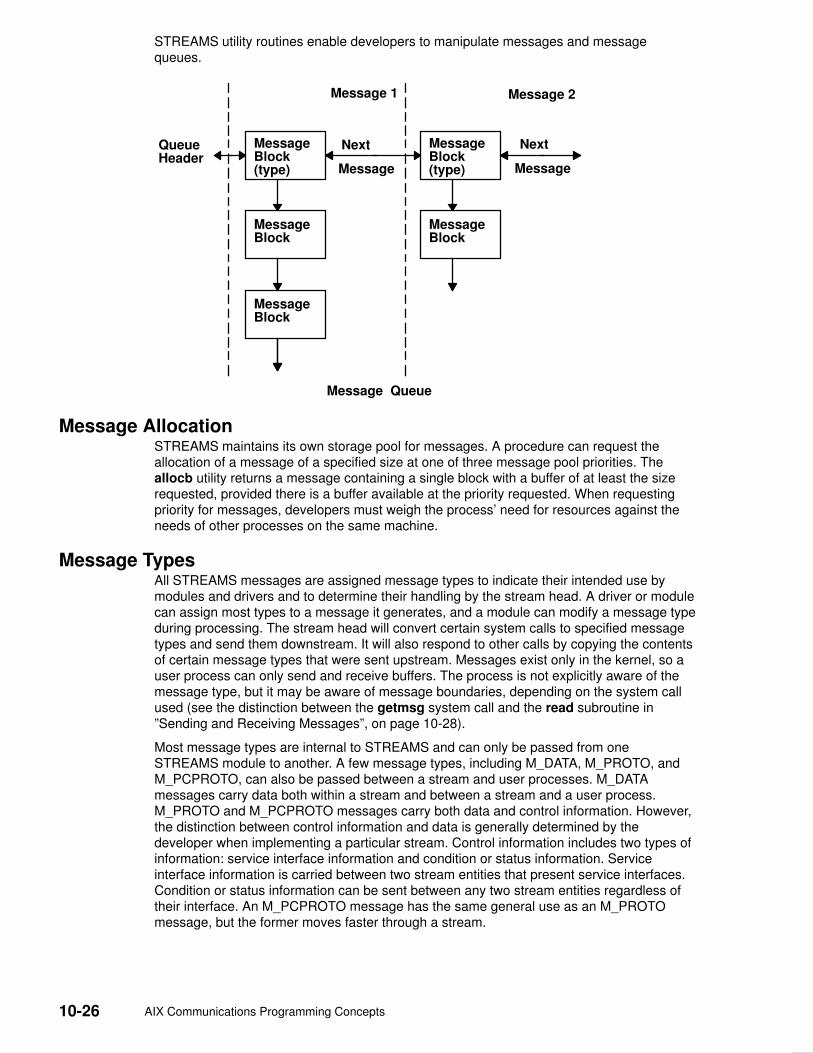
10-26 AIX Communications Programming Concepts
STREAMS utility routines enable developers to manipulate messages and messagequeues.
QueueHeader
MessageBlock(type)
MessageBlock
MessageBlock
Message 1 Message 2
Message
Next MessageBlock(type) Message
Next
MessageBlock
Message Queue
Message AllocationSTREAMS maintains its own storage pool for messages. A procedure can request theallocation of a message of a specified size at one of three message pool priorities. Theallocb utility returns a message containing a single block with a buffer of at least the sizerequested, provided there is a buffer available at the priority requested. When requestingpriority for messages, developers must weigh the process’ need for resources against theneeds of other processes on the same machine.
Message TypesAll STREAMS messages are assigned message types to indicate their intended use bymodules and drivers and to determine their handling by the stream head. A driver or modulecan assign most types to a message it generates, and a module can modify a message typeduring processing. The stream head will convert certain system calls to specified messagetypes and send them downstream. It will also respond to other calls by copying the contentsof certain message types that were sent upstream. Messages exist only in the kernel, so auser process can only send and receive buffers. The process is not explicitly aware of themessage type, but it may be aware of message boundaries, depending on the system callused (see the distinction between the getmsg system call and the read subroutine in”Sending and Receiving Messages”, on page 10-28).
Most message types are internal to STREAMS and can only be passed from oneSTREAMS module to another. A few message types, including M_DATA, M_PROTO, andM_PCPROTO, can also be passed between a stream and user processes. M_DATAmessages carry data both within a stream and between a stream and a user process.M_PROTO and M_PCPROTO messages carry both data and control information. However,the distinction between control information and data is generally determined by thedeveloper when implementing a particular stream. Control information includes two types ofinformation: service interface information and condition or status information. Serviceinterface information is carried between two stream entities that present service interfaces.Condition or status information can be sent between any two stream entities regardless oftheir interface. An M_PCPROTO message has the same general use as an M_PROTOmessage, but the former moves faster through a stream.
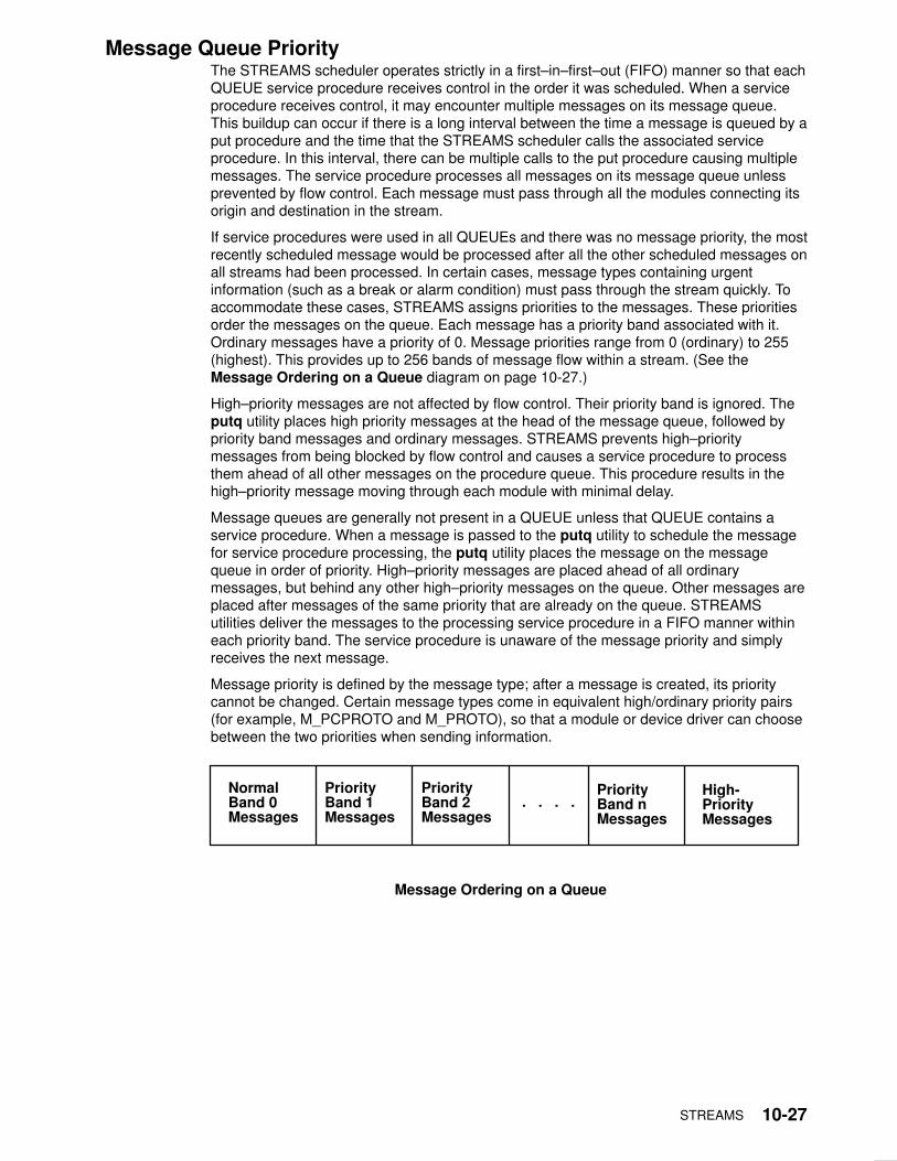
STREAMS 10-27
Message Queue PriorityThe STREAMS scheduler operates strictly in a first–in–first–out (FIFO) manner so that eachQUEUE service procedure receives control in the order it was scheduled. When a serviceprocedure receives control, it may encounter multiple messages on its message queue.This buildup can occur if there is a long interval between the time a message is queued by aput procedure and the time that the STREAMS scheduler calls the associated serviceprocedure. In this interval, there can be multiple calls to the put procedure causing multiplemessages. The service procedure processes all messages on its message queue unlessprevented by flow control. Each message must pass through all the modules connecting itsorigin and destination in the stream.
If service procedures were used in all QUEUEs and there was no message priority, the mostrecently scheduled message would be processed after all the other scheduled messages onall streams had been processed. In certain cases, message types containing urgentinformation (such as a break or alarm condition) must pass through the stream quickly. Toaccommodate these cases, STREAMS assigns priorities to the messages. These prioritiesorder the messages on the queue. Each message has a priority band associated with it.Ordinary messages have a priority of 0. Message priorities range from 0 (ordinary) to 255(highest). This provides up to 256 bands of message flow within a stream. (See theMessage Ordering on a Queue diagram on page 10-27.)
High–priority messages are not affected by flow control. Their priority band is ignored. Theputq utility places high priority messages at the head of the message queue, followed bypriority band messages and ordinary messages. STREAMS prevents high–prioritymessages from being blocked by flow control and causes a service procedure to processthem ahead of all other messages on the procedure queue. This procedure results in thehigh–priority message moving through each module with minimal delay.
Message queues are generally not present in a QUEUE unless that QUEUE contains aservice procedure. When a message is passed to the putq utility to schedule the messagefor service procedure processing, the putq utility places the message on the messagequeue in order of priority. High–priority messages are placed ahead of all ordinarymessages, but behind any other high–priority messages on the queue. Other messages areplaced after messages of the same priority that are already on the queue. STREAMSutilities deliver the messages to the processing service procedure in a FIFO manner withineach priority band. The service procedure is unaware of the message priority and simplyreceives the next message.
Message priority is defined by the message type; after a message is created, its prioritycannot be changed. Certain message types come in equivalent high/ordinary priority pairs(for example, M_PCPROTO and M_PROTO), so that a module or device driver can choosebetween the two priorities when sending information.
NormalBand 0Messages
PriorityBand 1Messages
PriorityBand 2Messages
. . . .PriorityBand nMessages
High-PriorityMessages
Message Ordering on a Queue

10-28 AIX Communications Programming Concepts
Sending and Receiving MessagesThe putmsg system call is a STREAMS–related system call that sends messages. It issimilar to the write subroutine. The putmsg system call provides a data buffer that isconverted into an M_DATA message. The system call can also provide a separate controlbuffer to be placed into an M_PROTO or M_PCPROTO block. The write subroutineprovides byte–stream data to be converted into M_DATA messages.
The getmsg system call is a STREAM–related system call that accepts messages. It issimilar to the read subroutine. One difference between the two calls is that the readsubroutine accepts only data (messages sent upstream to the stream head as messagetype M_DATA), such as the characters entered from the terminal. The getmsg system callcan simultaneously accept both data and control information (that is, a message sentupstream as type M_PROTO or M_PCPROTO). The getmsg system call also differs fromthe read subroutine in that it preserves message boundaries so that the same boundariesexist above and below the stream head (that is, between a user process and a stream). Theread subroutine generally ignores message boundaries, processing data as a byte stream.
Certain streamio operations, such as the I_STR operation, also cause messages to be sentor received on the stream. The I_STR operation provides the general ioctl capability of thecharacter input/output subsystem. A user process above the stream head can issue theputmsg system call, the getmsg system call, the I_STR operation, and certain otherSTREAMS–related functions. Other streamio operations perform functions that includechanging the state of the stream head, pushing and popping modules, or returning specialinformation.
In addition to message types that explicitly transfer data to a process, some messages sentupstream result in information transfer. When these messages reach the stream head, theyare transformed into various forms and sent to the user process. The forms include signals,error codes, and call return values.

STREAMS 10-29
Put and Service Procedures The procedures in the QUEUE are the software routines that process messages as theytransit the QUEUE. The processing is generally performed according to the message typeand can result in a modified message, new messages, or no message. A resultant messageis generally sent in the same direction in which it was received by the QUEUE, but may besent in either direction. A QUEUE always contains a put procedure and may also contain anassociated service procedure.
Put Procedures A put procedure is the QUEUE routine that receives messages from the preceding QUEUEin the stream. Messages are passed between QUEUEs by a procedure in one QUEUEcalling the put procedure contained in the following QUEUE. A call to the put procedure inthe appropriate direction is generally the only way to pass messages between modules.(Unless otherwise indicated, the term modules implies a module, driver, and stream head.)QUEUEs in pushable modules contain a put procedure. In general, there is a separate putprocedure for the read and write QUEUEs in a module because of the full–duplex operationof most streams.
A put procedure is associated with immediate (as opposed to deferred) processing on amessage. Each module accesses the adjacent put procedure as a subroutine. For example,suppose that modA, modB, and modC are three consecutive modules in a stream, withmodC connected to the stream head. If modA receives a message to be sent upstream,modA processes that message and then calls the modB put procedure. The modBprocedure processes the message and then calls the modC put procedure. Finally, themodC procedure processes the message and then calls the stream–head put procedure.
Thus, the message will be passed along the stream in one continuous processingsequence. This sequence has the benefit of completing the entire processing in a short timewith low overhead (subroutine calls). However, it may not be desirable to use this manner ofprocessing if this sequence is lengthy and the processing is implemented on a system withmultiple users. Using this manner of processing under those circumstances may be good forthis stream but detrimental to other streams since they may have to wait a long time to beprocessed.
In addition, some situations exist where the put procedure cannot immediately process themessage but must hold it until processing is allowed. The most typical examples of this area driver (which must wait until the current output completes before sending the nextmessage) and the stream head (which may have to wait until a process initiates the readsubroutine on the stream).
Service Procedures STREAMS allows a service procedure to be contained in each QUEUE, in addition to theput procedure, to address the above cases and for either purposes. A service procedure isnot required in a QUEUE and is associated with deferred processing. If a QUEUE has botha put and service procedure, message processing will generally be divided between theprocedures. The put procedure is always called first, from a preceding QUEUE. After the putprocedure completes its part of the message processing, it arranges for the serviceprocedure to be called by passing the message to the putq utility. The putq utility does twothings: it places the message on the message queue of the QUEUE, and it links the QUEUEto the end of the STREAMS scheduling queue. When the putq utility returns to the putprocedure, the procedure typically exits. Some time later, the service procedure will beautomatically called by the STREAMS scheduler.
The STREAMS scheduler is separate and distinct from the system process scheduler. It isconcerned only with QUEUEs linked on the STREAMS scheduling queue. The schedulercalls the service procedure of the scheduled QUEUE one at a time, in a FIFO manner.

10-30 AIX Communications Programming Concepts
Having both a put and service procedure in a QUEUE enables STREAMS to provide therapid response and the queuing required in systems with many users. The put procedureallows rapid response to certain data and events, such as software echoing of inputcharacters. Put procedures effectively have higher priority than any scheduled serviceprocedures. When called from the preceding STREAMS component, a put procedure startsbefore the scheduled service procedures of any QUEUE are started.
The service procedure implies message queuing. Queuing results in deferred processing ofthe service procedure, following all other QUEUEs currently on the scheduling queue. Forexample, terminal output, input erase, and kill processing would typically be performed in aservice procedure because this type of processing does not have to be as timely asechoing. Using a service procedure also allows processing time to be more evenly spreadamong multiple streams. As with the put procedure, there will generally be a separateservice procedure for each QUEUE in a module. The flow–control mechanism uses theservice procedures.

STREAMS 10-31
STREAMS Drivers and ModulesThis section compares operational features of character I/O device drivers with STREAMSdrivers and modules. It is intended for experienced developers of system character devicedrivers. The Drivers section includes a discussion of clone device drivers and the logdevice driver. The Modules section includes a discussion of the timod and the tirdwrmodules. The 64–Bit Support section discusses the impact of 64–bit support on STREAMSdrivers and modules.
EnvironmentNo user environment is generally available to STREAMS module procedures and drivers.Exceptions are the module and driver open and close routines, both of which have accessto the u_area of the calling process and both of which can sleep. Otherwise, a STREAMSdriver, module put procedure, and module service procedure have no user context and canneither sleep nor access the u_area.
Multiple streams can use a copy of the same module (that is, the same fmodsw), eachcontaining the same processing procedures. Therefore, modules must be reentrant, andcare must be exercised when using global data in a module. Put and service procedures arealways passed the address of the QUEUE (for example, in the Stream Detail diagram, onpage 10-31, Au calls the Bu put procedure with Bu as a parameter). The processingprocedure establishes its environment solely from the QUEUE contents, which is typicallythe private data (for example, state information).
10-32 AIX Communications Programming Concepts
Drivers At the interface to hardware devices, character I/O drivers have interrupt entry points; at thesystem interface, those same drivers generally have direct entry points (routines) to processopen, close, read, and write subroutines, and ioctl operations.
STREAMS device drivers have similar interrupt entry points at the hardware device interfaceand have direct entry points only for the open and close subroutines. These entry pointsare accessed using STREAMS, and the call formats differ from character device drivers.The put procedure is a driver’s third entry point, but it is a message (not system) interface.The stream head translates write subroutines and ioctl operations into messages andsends them downstream to be processed by the driver’s write QUEUE put procedure. Theread subroutine is seen directly only by the stream head, which contains the functionsrequired to process subroutines. A driver does not know about system interfaces other thanthe open and close subroutines, but it can detect the absence of a read subroutineindirectly if flow control propagates from the stream head to the driver and affects thedriver’s ability to send messages upstream.
For input processing, when the driver is ready to send data or other information to a userprocess, it does not wake up the process. It prepares a message and sends it to the readQUEUE of the appropriate (minor device) stream. The driver’s open routine generally storesthe QUEUE address corresponding to this stream.
For output processing, the driver receives messages from the stream head instead ofprocessing a write subroutine. If a message cannot be sent immediately to the hardware, itmay be stored on the driver’s write message queue. Subsequent output interrupts canremove messages from this queue.
Drivers and modules can pass signals, error codes, and return values to processes by usingmessage types provided for that purpose.
There are three special device drivers:
clone Finds and opens an unused minor device on another STREAMS driver.
log Provides an interface for the STREAMS error–logging and event–tracingprocesses.
sad Provides an interface for administrative operations.
Modules Modules have user context available only during the execution of their open and closeroutines. Otherwise, the QUEUEs forming the module are not associated with the userprocess at the end of the stream, nor with any other process. Because of this, QUEUEprocedures must not sleep when they cannot proceed; instead, they must explicitly returncontrol to the system. The system saves no state information for the QUEUE. The QUEUEmust store this information internally if it is to proceed from the same point on a later entry.
When a module or driver that requires private working storage (for example, for stateinformation) is pushed, the open routine must obtain the storage from external sources.STREAMS copies the module template from the fmodsw table for the I_PUSH operation, soonly fixed data can be contained in the module template. STREAMS has no automaticmechanism to allocate working storage to a module when it is opened. The sources for thestorage typically include either a module–specific kernel array, installed when the system isconfigured, or the STREAMS buffer pool. When using an array as a module storage pool,the maximum number of copies of the module that can exist at any one time must bedetermined. For drivers, this is typically determined from the physical devices connected,such as the number of ports on a multiplexor. However, certain types of modules may not beassociated with a particular external physical limit. For example, the CANONICAL moduleshown in the Module Reusability diagram, on page 10-33 could be used on different typesof streams.
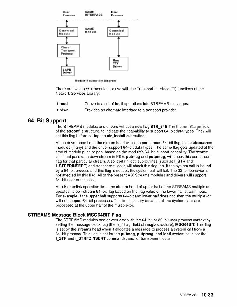
STREAMS 10-33
There are two special modules for use with the Transport Interface (TI) functions of theNetwork Services Library:
timod Converts a set of ioctl operations into STREAMS messages.
tirdwr Provides an alternate interface to a transport provider.
64–Bit SupportThe STREAMS modules and drivers will set a new flag STR_64BIT in the sc_flags fieldof the strconf_t structure, to indicate their capability to support 64–bit data types. They willset this flag before calling the str_install subroutine.
At the driver open time, the stream head will set a per–stream 64–bit flag, if all autopushedmodules (if any) and the driver support 64–bit data types. The same flag gets updated at thetime of module push or pop, based on the module’s 64–bit support capability. The systemcalls that pass data downstream in PSE, putmsg and putpmsg, will check this per–streamflag for that particular stream. Also, certain ioctl subroutines (such as I_STR andI_STRFDINSERT) and transparent ioctls will check this flag too. If the system call is issuedby a 64–bit process and this flag is not set, the system call will fail. The 32–bit behavior isnot affected by this flag. All of the present AIX Streams modules and drivers will support64–bit user processes.
At link or unlink operation time, the stream head of upper half of the STREAMS multiplexorupdates its per–stream 64–bit flag based on the flag value of the lower half stream head.For example, if the upper half supports 64–bit and lower half does not, then the multiplexorwill not support 64–bit processes. This is necessary because all the system calls areprocessed at the upper half of the multiplexor.
STREAMS Message Block MSG64BIT FlagThe STREAMS modules and drivers establish the 64–bit or 32–bit user process context bysetting the message block flag (the b_flag field of msgb structure), MSG64BIT. This flagis set by the streams head when it allocates a message to process a system call from a64–bit process. This flag is set for the putmsg, putpmsg, and ioctl system calls; for theI_STR and I_STRFDINSERT commands; and for transparent ioctls.

10-34 AIX Communications Programming Concepts
Transparent ioctlsThe third argument of the transparent ioctl is a pointer to the data in user space to be copiedin or out. This address is remapped properly by the ioctl system call. The streams driver ormodule passes M_COPYIN or M_COPYOUT messages to the stream head and the streamhead calls the copyin or copyout subroutines.
If the third argument of the ioctl subroutine points to a structure that contains a pointer (forexample, ptr64) or long, remapping is solved by a new structure, copyreq64, whichcontains a 64–bit user space pointer. If the message block flag is set to MSG64BIT, thedriver or module will pass M_COPYIN64 or M_COPYOUT64 to copy in or out a pointerwithin a structure. In this case, the stream head will call copyin64 or copyout64 to movethe data into or out of the user address space, respectively.
The copyreq64 structure uses the last unused cq_filler field to store the 64–bitaddress. The copyreq64 structure looks like the following example:
struct copyreq64 {
int cq_cmd; /* command type == ioc_cmd
*/
cred_t *cq_cr; /* pointer to full
credentials*/
int cq_id; /* ioctl id == ioc_id */
ioc_pad cq_ad; /* addr to copy data
to/from */
uint cq_size; /* number of bytes to copy
*/
int cq_flag; /* reserved */
mblk_t *cq_private; /* module’s private state
info*/
ptr64 cq_addr64; /* 64–bit address */
long cq_filler[2]; /* reserved */
};
The cq_addr64 field is added in the above structure and the size of the cq_filler isreduced, so overall size remains same. The driver or module first determines whether theMSG64BIT flag is set and, if so, stores the user–space 64–bit address in the cq_addr64field.

STREAMS 10-35
log Device Driver The log driver is a STREAMS software device driver that provides an interface for theSTREAMS error–logging and event–tracing processes. The log driver presents twoseparate interfaces:
• A function call interface in the kernel through which STREAMS drivers and modulessubmit log messages
• A subset of ioctl operations and STREAMS messages for interaction with a user–levelerror logger, a trace logger, or processes that need to submit their own log messages
Kernel InterfaceThe log messages are generated within the kernel by calls to the strlog utility.
User InterfaceThe log driver is opened using the clone interface, /dev/slog. Each open of /dev/slogobtains a separate stream to log. In order to receive log messages, a process must firstnotify the log driver whether it is an error logger or trace logger by using an I_STRoperation.
For the error logger, the I_STR operation has an ic_cmd parameter value of I_ERRLOGwith no accompanying data.
For the trace logger, the I_STR operation has an ic_cmd parameter value of I_TRCLOG,and must be accompanied by a data buffer containing an array of one or more trace_idsstructures. Each trace_ids structure specifies a mid, sid, and level field from whichmessages are accepted. The strlog subroutine accepts messages whose values in the midand sid fields exactly match those in the trace_ids structure, and whose level is less than orequal to the level given in the trace_ids structure. A value of –1 in any of the fields of thetrace_ids structure indicates that any value is accepted for that field.
At most, one trace logger and one error logger can be active at a time. Once the loggerprocess has identified itself by using the ioctl operation, the log driver will begin sendingmessages, subject to the restrictions previously noted. These messages are obtained byusing the getmsg system call. The control part of this message contains a log_ctl structure,which specifies the mid, sid, level, and flags fields, as well as the time in ticks since bootthat the message was submitted, the corresponding time in seconds since Jan. 1, 1970, anda sequence number. The time in seconds since 1970 is provided so that the date and timeof the message can be easily computed; the time in ticks since boot is provided so that therelative timing of log messages can be determined.
Different sequence numbers are maintained for the error–logging and trace–loggingstreams so that gaps in the sequence of messages can be determined. (During times ofhigh message traffic, some messages may not be delivered by the logger to avoid tying upsystem resources.) The data part of the message contains the unexpanded text of theformat string (null–terminated), followed by the arguments to the format string (up to thenumber specified by the NLOGARGS value), aligned on the first word boundary followingthe format string.
A process may also send a message of the same structure to the log driver, even if it is notan error or trace logger. The only fields of the log_ctl structure in the control part of themessage that are accepted are the level and flags fields. All other fields are filled in by thelog driver before being forwarded to the appropriate logger. The data portion must contain anull–terminated format string, and any arguments (up to NLOGARGS) must be packed oneword each, on the next word boundary following the end of the format string.

10-36 AIX Communications Programming Concepts
Attempting to issue an I_TRCLOG or I_ERRLOG operation when a logging process of thegiven type already exists results in the ENXIO error being returned. Similarly, ENXIO isreturned for I_TRCLOG operations without any trace_ids structures, or for anyunrecognized I_STR operations. Incorrectly formatted log messages sent to the driver by auser process are silently ignored (no error results).
Examples 1. The following is an example of I_ERRLOG notification:
struct strioctl ioc;
ioc.ic_cmd = I_ERRLOG;
ioc.ic_timout = 0; /* default timeout (15 secs.)*/
ioc.ic_len = 0;
ioc.ic_dp = NULL;
ioctl(log, I_STR, &ioc);
2. The following is an example of I_TRCLOG notification:
struct trace_ids tid[2];
tid[0].ti_mid = 2;
tid[0].ti_sid = 0;
tid[0].ti_level = 1;
tid[1].ti_mid = 1002;
tid[1].ti_sid = –1; /* any sub–id will be allowed*/
tid[1].ti_level = –1; /* any level will be allowed*/
ioc.ic_cmd = I_TRCLOG;
ioc.ic_timeout = 0;
ioc.ic_len = 2 * sizeof(struct trace_ids);
ioc.ic_dp = (char *)tid;
ioctl(log, I_STR, &ioc);
3. The following is an example of submitting a log message (no arguments):
struct strbuf ctl, dat;
struct log_ctl lc;
char *message = ”Honey, I’m working late again.”;
ctl.len = ctl.maxlen = sizeof(lc);
ctl.buf = (char *)&lc;
dat.len = dat.maxlen = strlen(message);
dat.buf = message;
lc.level = 0
lc.flags = SL_ERROS;
putmsg(log, &ctl, &dat, 0);

STREAMS 10-37
Configuring Drivers and Modules in the Portable StreamsEnvironment
Portable Streams Environment (PSE) drivers and modules are dynamically loaded andunloaded. To support this feature, each driver and module must have a configuration routinethat performs the necessary initialization and setup operations.
PSE provides the strload command to load drivers and modules. After loading theextension, the strload command calls the extension entry point using the SYS_CFGDD andSYS_CFGKMOD operations explained in the sysconfig subroutine section in AIX TechnicalReference.
Each PSE kernel extension configuration routine must eventually call the str_install utility tolink into STREAMS.
Commonly used extensions can be placed in a configuration file, which controls the normalsetup and tear–down of PSE. The configuration file allows more flexibility when loadingextensions by providing user–specified nodes and arguments. For a detailed description ofthe configuration file, see the strload command.
Loading and Unloading PSETo load PSE using the default configuration, enter the following command with no flags:
strload
To unload PSE, enter the following command with the unload flag, enter:
strload –u
Loading and Unloading a Driver or ModulePSE drivers and modules can be added and removed as necessary. This is especiallyhelpful during development of new extensions. To load only a new driver, enter the followingcommand:
strload –d newdriver
To unload the driver, enter:
strload –u –d newdriver
Modules can also be added and removed with the strload command by using the –m flaginstead of the –d flag.
PSE Configuration RoutinesTo support dynamic loading and unloading, each PSE extension must provide aconfiguration routine. This routine is called each time the extension is referenced in a loador unload operation. Detailed information about kernel extension configuration routines canbe found in the sysconfig subroutine section in AIX Kernel Extensions and Device SupportProgramming Concepts. However, PSE requires additional logic to successfully configurean extension.
To establish the linkage between PSE and the extension, the extension configuration routinemust eventually call the str_install utility. This utility performs the internal operationsnecessary to add or remove the extension from PSE internal tables.
The following code fragment provides an example of a minimal configuration routine for adriver called dgb. Device–specific configuration and initialization logic can be added asnecessary. The dgb_config entry point defines and initializes the strconf_t structurerequired by the str_install utility. In this example, the dgb_config operation retrieves theargument pointed to by the uiop parameter and uses it as an example of usage. Anextension may ignore the argument. The major number is required for drivers and isretrieved from the dev parameter. Since the dgb driver requires no initialization, its last step

10-38 AIX Communications Programming Concepts
is to perform the indicated operation by calling the str_install utility. Other drivers may needto perform other initialization steps either before or after calling the str_install utility.
#include <sys/device.h> /* for the CFG_* constants */
#include <sys/strconf.h> /* for the STR_* constants */
dgb_config(dev, cmd, uiop)
dev_t dev;
int cmd;
struct uio *uiop;
{
char buf[FMNAMESZ+1];
static strconf_t conf = {
”dgb”, &dgbinfo, STR_NEW_OPEN,
};
if (uiomove(buf, sizeof buf, UIO_WRITE, uiop))
return EFAULT;
buf[FMNAMESZ] = 0;
conf.sc_name = buf;
conf.sc_major = major(dev);
switch (cmd) {
case CFG_INIT: return str_install(STR_LOAD_DEV, &conf);
case CFG_TERM: return str_install(STR_UNLOAD_DEV, &conf);
default: return EINVAL;
}
}
A module configuration routine is similar to the driver routine, except a major number is notrequired and the calling convention is slightly different. The following code fragmentprovides an example of a minimal complete configuration routine:
#include <sys/device.h>
#include <sys/strconf.h>
/* ARGSUSED */
aoot_config(cmd, uiop)
int cmd;
struct uio *uiop;
{
static strconf_t conf = {
”aoot”, &aootinfo, STR_NEW_OPEN,
};
/* uiop ignored */
switch (cmd) {
case CFG_INIT: return str_install(STR_LOAD_MOD, &conf);
case CFG_TERM: return str_install(STR_UNLOAD_MOD, &conf);
default: return EINVAL;
}
}
For the strload command to successfully install an extension, the configuration routine ofeach extension must be marked as the entry point. Assuming the extension exists in a filecalled dgb.c, and has a configuration routine named dgb_config, a PSE object named dgbcan be created by the following commands:
cc –c dgb.c
ld –o dgb dgb.o –edgb_config –bimport:/lib/pse.exp –lcsys
A driver extension created in such a manner can be installed with the following command:
strload –d dgb
and removed with the following command:
strload –u –d dgb

STREAMS 10-39
Example ModuleThe following is a compilable example of a module called pass .
Note: Before it can be compiled, the code must exist in a file called pass.c.
#include <errno.h>
#include <sys/stream.h>
static int passclose(), passopen
(), passrput(), passwput();
static struct module_info minfo = { 0, ”pass”, 0, INFPSZ, 2048,
128 };
static struct qinit rinit = { passrput, 0, passopen, passclose,
0, &minfo };
static struct qinit winit = { passwput, 0, 0, 0, 0, &minfo };
struct streamtab passinfo = { &rinit, &winit };
static int
passclose (queue_t *q)
{
return 0;
}
static int
passopen (queue_t *q, dev_t *devp, int flag, int sflag, cred_t
*credp)
{
return 0;
}
static int
passrput (queue_t *q, mblk_t *mp)
{
putnext(q, mp);
return 0;
}
static int
passwput (queue_t *q, mblk_t *mp)
{
putnext(q, mp);
return 0;
}
#include <sys/device.h>
#include <sys/strconf.h>
int
passconfig(int cmd, struct uio *uiop)
{
static strconf_t conf = {
”pass”, &passinfo, STR_NEW_OPEN,
};
switch (cmd) {
case CFG_INIT: return str_install(STR_LOAD_MOD, &conf);
case CFG_TERM: return str_install(STR_UNLOAD_MOD, &conf);
default: return EINVAL;
}
}
The object named pass can be created using the following commands:
cc –c pass.c
ld –o pass pass.o –epass_config –bimport:/lib/pse.exp –lcsys
Use the following command to install the module:
strload –m pass
Use the following command to remove the module:
strload –u –m pass

10-40 AIX Communications Programming Concepts
An Asynchronous Protocol STREAMS Example In this example, suppose that the computer supports different kinds of asynchronousterminals, each logging in on its own port. The port hardware is limited in function; forexample, it detects and reports line and modem status, but does not check parity.
Communications software support for these terminals is provided using aSTREAMS–implemented asynchronous protocol. The protocol includes a variety of optionsthat are set when a terminal operator dials in to log on. The options are determined by agetty–type STREAMS user–written process, getstrm, which analyzes data sent to itthrough a series of dialogs (prompts and responses) between the process and terminaloperator.
Note: The getstrm process used in this example is a nonexistent process. It is notsupported by this system.
The process sets the terminal options for the duration of the connection by pushing modulesonto the stream by sending control messages to cause changes in modules (or in thedevice driver) already on the stream. The options supported include:
• ASCII or EBCDIC character codes
• For ASCII code, the parity (odd, even, or none)
• Echoing or no echoing of input characters
• Canonical input and output processing or transparent (raw) character handling
These options are set with the following modules:
CHARPROC Provides input character–processing functions, including dynamicallysettable (using control messages passed to the module) character echoand parity checking. The module default settings are meant to echocharacters and do not check character parity.
CANONPROC Performs canonical processing on ASCII characters upstream anddownstream, this module performs some processing in a differentmanner from the standard character I/O tty subsystem.
ASCEBC Translates EBCDIC code to ASCII, upstream, and ASCII to EBCDIC,downstream.
Note: The modules used in this example are nonexistent. They are not supported by thissystem.
Initializing the StreamAt system initialization a user–written process, getstrm, is created for each tty port. Thegetstrm process opens a stream to its port and pushes the CHARPROC module onto thestream by use of a I_PUSH operation. Then, the process issues a getmsg system call tothe stream and sleeps until a message reaches the stream head. The stream is now in itsidle state.
The initial idle stream contains only one pushable module, CHARPROC. The device driveris a limited–function, raw tty driver connected to a limited–function communication port. Thedriver and port transparently transmit and receive one unbuffered character at a time.
Upon receipt of initial input from a tty port, the getstrm process establishes a connectionwith the terminal, analyzes the option requests, verifies them, and issues STREAMSsubroutines to set the options. After setting up the options, the getstrm process creates auser application process. Later, when the user terminates that application, the getstrmprocess restores the stream to its idle state by use of subroutines.
The next step is to analyze in more detail how the stream sets up the communicationsoptions.

STREAMS 10-41
Using Messages in the ExampleThe getstrm process has issued a getmsg system call and is sleeping until the arrival of amessage from the stream head. Such a message would result from the driver detectingactivity on the associated tty port.
An incoming call arrives at port 1 and causes a ring–detect signal in the modem. The driverreceives the ring signal, answers the call, and sends upstream an M_PROTO messagecontaining information indicating an incoming call. The getstrm process is notified of allincoming calls, although it can choose to refuse the call because of system limits. In this idlestate, the getstrm process will also accept M_PROTO messages indicating, for example,error conditions such as detection of line or modem problems on the idle line.
The M_PROTO message containing notification of the incoming call flows upstream fromthe driver into the CHARPROC module. The CHARPROC module inspects the messagetype, determines that message processing is not required, and passes the unmodifiedmessage upstream to the stream head. The stream head copies the message into thegetmsg buffers (one buffer for control information, the other for data) associated with thegetstrm process and wakes up the process. The getstrm process sends its acceptance ofthe incoming call with a putmsg system call, which results in a downstream M_PROTOmessage to the driver.
Then, the getstrm process sends a prompt to the operator with a write subroutine andissues a getmsg system call to receive the response. A read subroutine could have beenused to receive the response, but the getmsg system call allows concurrent monitoring forcontrol (M_PROTO and M_PCPROTO) information. The getstrm process will now sleepuntil the response characters, or information regarding possible error conditions detected bymodules or driver, are sent upstream.
The first response, sent upstream in an M_DATA block, indicates that the code set is ASCIIand that canonical processing is requested. The getstrm process implements these optionsby pushing the CANONPROC module onto the stream, above the CHARPROC module, toperform canonical processing on the input ASCII characters.
The response to the next prompt requests even–parity checking. The getstrm processsends an I_STR operation to the CHARPROC module, requesting the module to performeven–parity checking on upstream characters. When the dialog indicates thatprotocol–option setting is complete, the getstrm process creates an application process. Atthe end of the connection, the getstrm process will pop the CANONPROC module and thensend an I_STR operation to the CHARPROC module requesting that module restore theno–parity idle state (the CHARPROC module remains on the stream).
As a result of the above dialogs, the terminal at port 1 operates in the followingconfiguration:
• ASCII, even parity
• Echo
• Canonical processing
In similar fashion, an operator at a different type of terminal on port 2 requests a different setof options, resulting in the following configuration:
• EBCDIC
• No echo
• Canonical processing
The resultant streams for the two ports are shown in the Asynchronous TerminalSTREAMS diagram on page 10-42. For port 1, the modules in the stream areCANONPROC and CHARPROC.
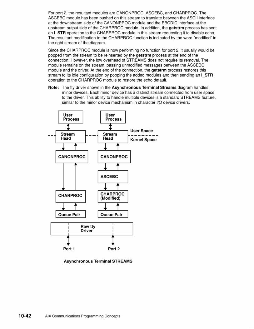
10-42 AIX Communications Programming Concepts
For port 2, the resultant modules are CANONPROC, ASCEBC, and CHARPROC. TheASCEBC module has been pushed on this stream to translate between the ASCII interfaceat the downstream side of the CANONPROC module and the EBCDIC interface at theupstream output side of the CHARPROC module. In addition, the getstrm process has sentan I_STR operation to the CHARPROC module in this stream requesting it to disable echo.The resultant modification to the CHARPROC function is indicated by the word ”modified” inthe right stream of the diagram.
Since the CHARPROC module is now performing no function for port 2, it usually would bepopped from the stream to be reinserted by the getstrm process at the end of theconnection. However, the low overhead of STREAMS does not require its removal. Themodule remains on the stream, passing unmodified messages between the ASCEBCmodule and the driver. At the end of the connection, the getstrm process restores thisstream to its idle configuration by popping the added modules and then sending an I_STRoperation to the CHARPROC module to restore the echo default.
Note: The tty driver shown in the Asynchronous Terminal Streams diagram handlesminor devices. Each minor device has a distinct stream connected from user spaceto the driver. This ability to handle multiple devices is a standard STREAMS feature,similar to the minor device mechanism in character I/O device drivers.
Asynchronous Terminal STREAMS
UserProcess
UserProcess
StreamHead
StreamHead
CANONPROC CANONPROC
ASCEBC
CHARPROC(Modified)
CHARPROC
Queue Pair Queue Pair
Raw ttyDriver
Port 1 Port 2
User Space
Kernel Space

STREAMS 10-43
Other User FunctionsThe previous example illustrates basic STREAMS concepts. However, more efficientSTREAMS calls or mechanisms could have been used in place of those described earlier.
For example, the initialization process that created a getstrm process for each tty port couldhave been implemented as a ”supergetty” by use of the STREAMS–related poll subroutine.The poll subroutine allows a single process to efficiently monitor and control multiplestreams. The ”supergetty” process would handle all of the stream and terminal protocolinitialization and would create application processes only for established connections.
Otherwise, the M_PROTO notification sent to the getstrm process could be sent by thedriver as an M_SIG message that causes a specified signal to be sent to the process. Errorand status information can also be sent upstream from a driver or module to user processesusing different message types. These messages will be transformed by the stream headinto a signal or error code.
Finally, a I_STR operation could be used in place of a putmsg system call M_PROTOmessage to send information to a driver. The sending process must receive an explicitresponse from an I_STR operation by a specified time period, or an error will be returned. Aresponse message must be sent upstream by the destination module or driver to betranslated into the user response by the stream head.
Kernel ProcessingThis section describes STREAMS kernel operations and associates them, where relevant,with user–level system calls. As a result of initializing operations and pushing a module, thestream for port 1 has the configuration shown in the Operational Stream diagram.
Here, the upstream QUEUE is also referred to as the read QUEUE, reflecting the messageflow in response to a read subroutine. The downstream QUEUE is referred to as the writeQUEUE.
StreamHead
CANONPROCModule
CHARPROCModule
Queue Pair
Raw ttyDevice Driver
Write Read
10-44 AIX Communications Programming Concepts
Read–Side ProcessingIn the example, read–side processing consists of driver processing, CHARPROCprocessing, and CANONPROC processing.
Driver Processing
In the example, the user process has blocked on the getmsg subroutine while waiting for amessage to reach the stream head, and the device driver independently waits for input of acharacter from the port hardware or for a message from upstream. Upon receipt of an inputcharacter interrupt from the port, the driver places the associated character in an M_DATAmessage, allocated previously. Then, the driver sends the message to the CHARPROCmodule by calling the CHARPROC upstream put procedure. On return from theCHARPROC module, the driver calls the allocb utility routine to get another message forthe next character.
CHARPROC
The CHARPROC module has both put and service procedures on its read side. As a result,the other QUEUEs in the modules also have put and service procedures.
When the driver calls the CHARPROC read–QUEUE put procedure, the procedure checksprivate data flags in the QUEUE. In this case, the flags indicate that echoing is to beperformed (recall that echoing is optional and that we are working with port hardware thatcannot automatically echo). The CHARPROC module causes the echo to be transmittedback to the terminal by first making a copy of the message with a STREAMS utility. Then,the CHARPROC module uses another utility to obtain the address of its own write QUEUE.Finally, the CHARPROC read put procedure calls its write put procedure and passes it themessage copy. The write procedure sends the message to the driver to effect the echo andthen returns to the read procedure.
This part of read–side processing is implemented with put procedures so that the entireprocessing sequence occurs as an extension of the driver input–character interrupt. TheCHARPROC read and write put procedures appear as subroutines (nested in the case ofthe write procedure) to the driver. This manner of processing is intended to produce thecharacter echo in a minimal time frame.
After returning from echo processing, the CHARPROC read put procedure checks anotherof its private data flags and determines that parity checking should be performed on theinput character. Usually, parity would be checked as part of echo processing. However, forthis example, parity is checked only when the characters are sent upstream. As a result,parity checking can be deferred along with the canonical processing. The CHARPROCmodule uses the putq utility to schedule the (original) message for parity–check processingby its read service procedure. When the CHARPROC read service procedure is complete, itforwards the message to the read put procedure of the CANONPROC module. If paritychecking were not required, the CHARPROC put procedure would call the CANONPROCput procedure directly.
CANONPROC
The CANONPROC module performs canonical processing. As implemented, all readQUEUE processing is performed in its service procedure. The CANONPROC put proceduresimply calls the putq utility to schedule the message for its read service procedure, andthen exits. The service procedure extracts the character from the message buffer andplaces it in the line buffer contained in another M_DATA message it is constructing. Then,the message containing the single character is returned to the buffer pool. If the characterreceived was not an end–of–line, the CANONPROC module exits. Otherwise, a completeline has been assembled and the CANONPROC module sends the message upstream tothe stream head, which unlocks the user process from the getmsg subroutine call andpasses it the contents of the message.

STREAMS 10-45
Write–Side ProcessingThe write side of the stream carries two kinds of messages from the user process: streamiomessages for the CHARPROC module and M_DATA messages to be output to the terminal.
The streamio messages are sent downstream as a result of an I_STR operation. When theCHARPROC module receives a streamio message type, it processes the messagecontents to modify internal QUEUE flags and then uses a utility to send an acknowledgmentmessage upstream (read side) to the stream head. The stream head acts on theacknowledgment message by unblocking the user from the streamio message.
For terminal output, it is presumed that M_DATA messages, sent by write subroutines,contain multiple characters. In general, STREAMS returns to the user process immediatelyafter processing the write subroutine so that the process may send additional messages.Flow control will eventually block the sending process. The messages can queue on thewrite side of the driver because of character–transmission timing. When a message isreceived by the driver’s write put procedure, the procedure will use the putq utility to placethe message on its write–side service message queue if the driver is currently transmitting aprevious message buffer. However, there is generally no write–QUEUE service procedure ina device driver. Driver output–interrupt processing takes the place of scheduling andperforms the service procedure functions, removing messages from the queue.
AnalysisFor reasons of efficiency, a module implementation would generally avoid placing onecharacter per message and using separate routines to echo and parity–check eachcharacter, as done in this example. Nevertheless, even this design yields potential benefits.Consider a case in which an alternative and more intelligent port hardware was substituted.If the hardware processed multiple input characters and performed the echo andparity–checking functions of the CHARPROC module, then the new driver could beimplemented to present the same interface as the CHARPROC module. Other modulessuch as CANONPROC could continue to be used without modification.

10-46 AIX Communications Programming Concepts
Differences Between Portable Streams Environment and V.4STREAMS
Portable Streams Environment (PSE) was implemented from the AT&T UNIX System VRelease 4, Programmer’s Guide: STREAMS document. It is designed for compatibility withexisting STREAMS applications and modules that adhere to the STREAMS designguidelines.
Extensions to STREAMSIn some areas, the STREAMS definition is extended to enhance functionality. Theseenhancements include:
• Extended read modes. PSE supports an extra read mode, RFILL, which requests thatthe stream head fill a buffer completely before returning to the application. This is used inconjunction with a cooperating module and M_READ messages.
• The putctl2 utility. A new utility routine, putctl2, is supported for creating M_ERRORmessages with 2 bytes of data. The parameters are the same as for the putctl1 utility.
• Autopush names. The PSE autopush command accepts device names in place of majornumbers on the command line. It then translates names into major numbers with the helpof the sc module.
Note: Although these extensions can be used freely in this operating system, their uselimits portability.
Differences in PSEAlthough PSE is written to the specifications in the AT&T document, there are places inwhich compatibility with the specification is not implemented or is not possible. Thesedifferences are:
• Include files. Not all structures and definitions in AT&T include files are discussed in theSTREAMS documentation. Module and application writers can use only those symbolsspecified in the documentation.
• Module configuration. The configuration of modules and devices under PSE is differentfrom AT&T System V Release 4 in that there is no master file or related structures. PSEmaintains an fmodsw table for modules, and a dmodsw table for devices andmultiplexors. Entries are dynamically placed in these tables as modules are loaded into arunning system. Similarly, PSE normally supports init routines for modules and devices,but not start routines.
• Logging device. The STREAMS logging device is named /dev/slog. The /dev/log noderefers to a different type of logging device.
• Structure definitions. PSE supports the standard STREAMS structure definitions in termsof field names and types, but also includes additional fields for host–specific needs.Modules and applications should not depend on the field position or structure size astaken from STREAMS documentation. Also, PSE does not support the notion ofexpanded fundamental types and the associated _STYPES definition.
• Queue flags. PSE defines, but does not implement, the QBACK and QHLIST queueflags.

STREAMS 10-47
• Memory allocation. PSE does not support the rmalloc, rminit, and rmfree memoryallocation routines.
• Named streams. PSE does not support named streams and the associated fdetachprogram.
• Terminals. PSE does not include STREAMS–based terminals or the related modules andutilities (including job control primitives). However, nothing in PSE preventsSTREAMS–based terminals from being added.
• Network selection. PSE does not support the V.4 Network Selection andName–to–Address Mapping extensions to the TLI (Transport Layer Interface).
10-48 AIX Communications Programming Concepts
List of Streams Commands System management commands are arranged by the following functions:
• Configuring
• Maintaining
See ”List of STREAMS Programming References”, on page 10-49 for information aboutSTREAMS operations, modules and drivers, subroutines, a function, system calls, andutilities.
Configuring
autopush Configures lists of automatically pushed STREAMS modules.
strchg Changes stream configuration.
strconf Queries stream configuration.
strload Loads and configures Portable Streams Environment (PSE).
Maintaining
scls Produces a list of module and driver names.
strace Prints STREAMS trace messages.
strclean Cleans up the STREAMS error logger.
strerr (Daemon) Receives error log messages from the STREAMS log driver.

STREAMS 10-49
List of STREAMS Programming ReferencesThe list includes:
• Operation
• Modules and Drivers
• Subroutines
• Function
• System Calls
• Utilities
See ”List of STREAMS Commands”, on page 10-48 for information about STREAMScommands for configuring and managing.
Operation
streamio Lists the ioctl operations which perform a variety of control functions onstreams.
Modules and Drivers The following modules and drivers are used in the STREAMS environment. The referencesare found in the list of subroutines.
pfmod Selectively removes upstream data messages on a stream.
timod Converts a set of streamio operations into STREAMS messages.
tirdwr Supports the Transport Interface functions of the Network Services library.
xtiso Provides access to sockets–based protocols to STREAMS applications.
dlpi Provides an interface to the data link provider.
Subroutines
t_accept Accepts a connect request.
t_alloc Allocates a library structure.
t_bind Binds an address to a transport endpoint.
t_close Closes a transport endpoint.
t_connect Establishes a connection with another transport user.
t_error Produces an error message.
t_free Frees a library structure.
t_getinfo Gets protocol–specific service information.
t_getstate Gets the current state.
t_listen Listens for a connect request.
t_look Looks at the current event on a transport endpoint.
t_open Establishes a transport endpoint.
t_optmgmt Manages options for a transport endpoint.
t_rcv Receives normal data or expedited data sent over a connection.
t_rcvconnect Receives the confirmation from a connect request.
t_rcvdis Retrieves information from disconnect.

10-50 AIX Communications Programming Concepts
t_rcvrel Acknowledges receipt of an orderly release indication.
t_rcvudata Receives a data unit.
t_rcvuderr Receives a unit data error indication.
t_snd Sends data or expedited data over a connection.
t_snddis Sends a user–initiated disconnect request.
t_sndrel Initiates an orderly release of a transport connection.
t_sndudata Sends a data unit to another transport user.
t_sync Synchronizes transport library.
t_unbind Disables a transport endpoint.
Function
isastream Tests a file descriptor.
System Calls
getmsg Gets the next message off a stream.
getpmsg Gets the next priority message off a stream.
putmsg Sends a message on a stream.
putpmsg Sends a priority message on a stream.
Utilities The following utilities are used by STREAMS:
adjmsg Trims bytes in a message.
allocb Allocates message and data blocks.
backq Returns a pointer to the queue behind a given queue.
bcanput Tests for flow control in the given priority band.
bufcall Recovers from a failure of the allocb utility.
canput Tests for available room in a queue.
copyb Copies a message block.
copymsg Copies a message.
datamsg Tests whether message is a data message.
dupb Duplicates a message–block descriptor.
dupmsg Duplicates a message.
enableok Enables a queue to be scheduled for service.
esballoc Allocates message and data blocks.
flushband Flushes the messages in a given priority band.
flushq Flushes a queue.
freeb Frees a single message block.
freemsg Frees all message blocks in a message.
getadmin Returns a pointer to a module.
getmid Returns a module ID.
getq Gets a message from a queue.
insq Puts a message at a specific place in a queue.

STREAMS 10-51
linkb Concatenates two messages into one.
mi_bufcall Provides a reliable alternative to the bufcall utility.
mi_close_comm
Performs housekeeping during STREAMS module close operations.
mi_next_ptr Traverses a STREAMS module’s linked list of open streams.
mi_open_comm
Performs housekeeping during STREAMS module open operations.
msgdsize Gets the number of data bytes in a message.
noenable Prevents a queue from being scheduled.
OTHERQ Returns the pointer to the mate queue.
pullupmsg Concatenates and aligns bytes in a message.
putbq Returns a message to the beginning of a queue.
putctl Passes a control message.
putctl1 Passes a control message with a one–byte parameter.
putnext Passes a message to the next queue.
putq Puts a message on a queue.
qenable Enables a queue.
qreply Sends a message on a stream in the reverse direction.
qsize Finds the number of messages on a queue.
RD Gets the pointer to the read queue.
rmvb Removes a message block from a message.
rmvq Removes a message from a queue.
splstr Sets the processor level.
splx Terminates a section of code.
srv Services queued messages for STREAMS modules or drivers.
str_install Installs STREAMS modules and drivers.
strlog Generates STREAMS error–logging and event–tracing messages.
strqget Obtains information about a queue or band of the queue.
testb Checks for an available buffer.
timeout Schedules a function to be called after a specified interval.
unbufcall Cancels a bufcall request.
unlinkb Removes a message block from the head of a message.
untimeout Cancels a pending time–out request.
unweldq Removes a previously established weld connection between STREAMSqueues.
wantio Register direct I/O entry points with the stream head.
weldq Establishes a unidirectional connection between STREAMS queues.
WR Retrieves a pointer to the write queue.
10-52 AIX Communications Programming Concepts
Transport Service Library Interface Overview Network applications that are either system–provided or developed in–house require aprogramming interface to the network, such as Transmission Control Protocol/InternetProtocol (TCP/IP). The transport level programming interface provides applicationdevelopers a means of getting to the network protocols without requiring the knowledge ofprotocol–specific semantics, the framework which the protocols are loaded or thecomplexity of kernel interfaces.
Two libraries are provided for accessing well–known protocols such as TCP/IP. Theselibraries are:
• Transport Library Interface (TLI)
• X/OPEN Transport Library Interface (XTI)
These library interfaces are provided in addition to the existing socket system calls.Generally speaking, well–known protocols, such as TCP/IP and Open SystemsInterconnection (OSI), are divided into two parts:
• Transport layer and below are in the kernel space
• Session layer and above services are in the user space.
AIX supplies the socket–based TCP/IP protocol suites as a part of the base system. It alsosupplies the socket system calls and socket library calls (libc.a) for the existing applicationswhich have been developed using the sockets applications programming interface (API).
TLI is a library that is used for porting applications developed using the AT&T SystemV–based UNIX operating systems.
XTI is a library implementation, as specified by X/OPEN CAE Specification of X/OpenTransport Interface and fully conformant to X/OPEN XPG4 Common ApplicationEnvironment (CAE) specification, that defines a set of transport–level services that areindependent of any specific transport provider’s protocol or its framework.
The purpose of XTI is to provide a universal programming interface for the transport layerfunctions regardless of the transport layer protocols, how the framework of the transportlayer protocols are implemented, or the type of UNIX operating system. For example, anapplication which writes to XTI should not have to know that the service provider is writtenusing STREAMS or sockets. The application accesses the transport end point (using thereturned handle, fd, of the t_open subroutine) and requests and receives indications fromthe well–known service primitives. If desired or necessary, applications can obtain anyprotocol–specific information by calls to the t_info subroutine.
Both TLI and XTI are implemented using STREAMS. This implementation includes thefollowing members:
• Transport Library – libtli.a
• X/OPEN Transport Library – libxti.a
• STREAMS driver – Sends STREAMS messages initiated from the XTI or TLI library tothe sockets–based network protocol (as in the case of TCP/IP) or to other STREAMSdrivers (as in the case of Netware).
The TLI (libtli.a) and XTI (libxti.a) libraries are shared libraries. This means thatapplications can run without recompiling, even though the system may update the librariesin the future.
The TLI and XTI calls syntax is similar. For the most part, XTI is a superset of TLI in termsof definitions, clarification of usage, and robustness of return codes. For specific XTI usageand return codes see X/OPEN CAE Specification of X/Open Transport Interface and the listof X/Open Transport Interface Library Subroutines.
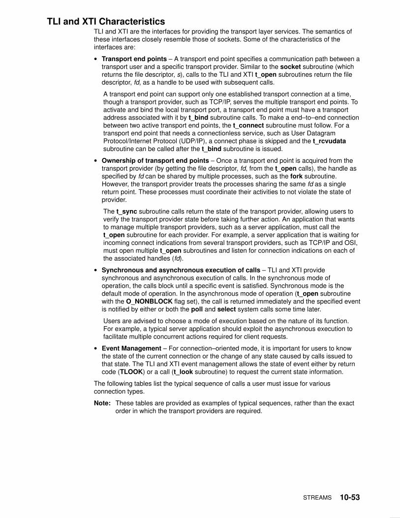
STREAMS 10-53
TLI and XTI CharacteristicsTLI and XTI are the interfaces for providing the transport layer services. The semantics ofthese interfaces closely resemble those of sockets. Some of the characteristics of theinterfaces are:
• Transport end points – A transport end point specifies a communication path between atransport user and a specific transport provider. Similar to the socket subroutine (whichreturns the file descriptor, s), calls to the TLI and XTI t_open subroutines return the filedescriptor, fd, as a handle to be used with subsequent calls.
A transport end point can support only one established transport connection at a time,though a transport provider, such as TCP/IP, serves the multiple transport end points. Toactivate and bind the local transport port, a transport end point must have a transportaddress associated with it by t_bind subroutine calls. To make a end–to–end connectionbetween two active transport end points, the t_connect subroutine must follow. For atransport end point that needs a connectionless service, such as User DatagramProtocol/Internet Protocol (UDP/IP), a connect phase is skipped and the t_rcvudatasubroutine can be called after the t_bind subroutine is issued.
• Ownership of transport end points – Once a transport end point is acquired from thetransport provider (by getting the file descriptor, fd, from the t_open calls), the handle asspecified by fd can be shared by multiple processes, such as the fork subroutine.However, the transport provider treats the processes sharing the same fd as a singlereturn point. These processes must coordinate their activities to not violate the state ofprovider.
The t_sync subroutine calls return the state of the transport provider, allowing users toverify the transport provider state before taking further action. An application that wantsto manage multiple transport providers, such as a server application, must call thet_open subroutine for each provider. For example, a server application that is waiting forincoming connect indications from several transport providers, such as TCP/IP and OSI,must open multiple t_open subroutines and listen for connection indications on each ofthe associated handles (fd).
• Synchronous and asynchronous execution of calls – TLI and XTI providesynchronous and asynchronous execution of calls. In the synchronous mode ofoperation, the calls block until a specific event is satisfied. Synchronous mode is thedefault mode of operation. In the asynchronous mode of operation (t_open subroutinewith the O_NONBLOCK flag set), the call is returned immediately and the specified eventis notified by either or both the poll and select system calls some time later.
Users are advised to choose a mode of execution based on the nature of its function.For example, a typical server application should exploit the asynchronous execution tofacilitate multiple concurrent actions required for client requests.
• Event Management – For connection–oriented mode, it is important for users to knowthe state of the current connection or the change of any state caused by calls issued tothat state. The TLI and XTI event management allows the state of event either by returncode (TLOOK) or a call (t_look subroutine) to request the current state information.
The following tables list the typical sequence of calls a user must issue for variousconnection types.
Note: These tables are provided as examples of typical sequences, rather than the exactorder in which the transport providers are required.
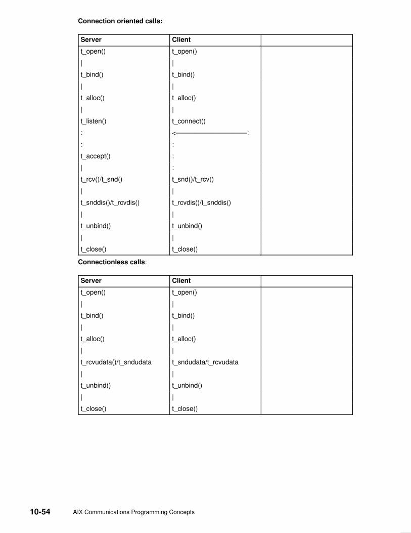
10-54 AIX Communications Programming Concepts
Connection oriented calls:
Server Client
t_open() t_open()
| |
t_bind() t_bind()
| |
t_alloc() t_alloc()
| |
t_listen() t_connect()
: <–––––––––––––––––––:
: :
t_accept() :
| :
t_rcv()/t_snd() t_snd()/t_rcv()
| |
t_snddis()/t_rcvdis() t_rcvdis()/t_snddis()
| |
t_unbind() t_unbind()
| |
t_close() t_close()
Connectionless calls:
Server Client
t_open() t_open()
| |
t_bind() t_bind()
| |
t_alloc() t_alloc()
| |
t_rcvudata()/t_sndudata t_sndudata/t_rcvudata
| |
t_unbind() t_unbind()
| |
t_close() t_close()

Transmission Control Protocol/Internet Protocol 11-1
Chapter 11. Transmission Control Protocol/InternetProtocol
Transmission Control Protocol/Internet Protocol (TCP/IP) includes a suite of protocols thatspecify communications standards between computers as well as detail conventions forrouting and interconnecting networks. TCP/IP is used extensively on the Internet andconsequently allows research institutions, colleges and universities, government, andindustry to communicate with each other. This chapter provides programming references formethods, file formats, and RFCs used with TCP/IP.
For information on name resolution, see Network Address Translation, on page 9-31
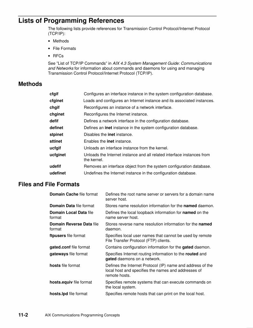
11-2 AIX Communications Programming Concepts
Lists of Programming ReferencesThe following lists provide references for Transmission Control Protocol/Internet Protocol(TCP/IP):
• Methods
• File Formats
• RFCs
See ”List of TCP/IP Commands” in AIX 4.3 System Management Guide: Communicationsand Networks for information about commands and daemons for using and managingTransmission Control Protocol/Internet Protocol (TCP/IP).
Methods
cfgif Configures an interface instance in the system configuration database.
cfginet Loads and configures an Internet instance and its associated instances.
chgif Reconfigures an instance of a network interface.
chginet Reconfigures the Internet instance.
defif Defines a network interface in the configuration database.
definet Defines an inet instance in the system configuration database.
stpinet Disables the inet instance.
sttinet Enables the inet instance.
ucfgif Unloads an interface instance from the kernel.
ucfginet Unloads the Internet instance and all related interface instances fromthe kernel.
udefif Removes an interface object from the system configuration database.
udefinet Undefines the Internet instance in the configuration database.
Files and File Formats
Domain Cache file format Defines the root name server or servers for a domain nameserver host.
Domain Data file format Stores name resolution information for the named daemon.
Domain Local Data fileformat
Defines the local loopback information for named on thename server host.
Domain Reverse Data fileformat
Stores reverse name resolution information for the nameddaemon.
ftpusers file format Specifies local user names that cannot be used by remoteFile Transfer Protocol (FTP) clients.
gated.conf file format Contains configuration information for the gated daemon.
gateways file format Specifies Internet routing information to the routed andgated daemons on a network.
hosts file format Defines the Internet Protocol (IP) name and address of thelocal host and specifies the names and addresses ofremote hosts.
hosts.equiv file format Specifies remote systems that can execute commands onthe local system.
hosts.lpd file format Specifies remote hosts that can print on the local host.
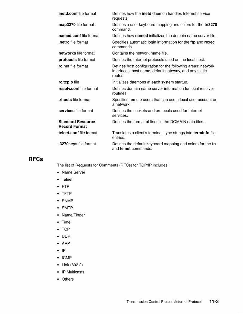
Transmission Control Protocol/Internet Protocol 11-3
inetd.conf file format Defines how the inetd daemon handles Internet servicerequests.
map3270 file format Defines a user keyboard mapping and colors for the tn3270command.
named.conf file format Defines how named initializes the domain name server file.
.netrc file format Specifies automatic login information for the ftp and rexeccommands.
networks file format Contains the network name file.
protocols file format Defines the Internet protocols used on the local host.
rc.net file format Defines host configuration for the following areas: networkinterfaces, host name, default gateway, and any staticroutes.
rc.tcpip file Initializes daemons at each system startup.
resolv.conf file format Defines domain name server information for local resolverroutines.
.rhosts file format Specifies remote users that can use a local user account ona network.
services file format Defines the sockets and protocols used for Internetservices.
Standard ResourceRecord Format
Defines the format of lines in the DOMAIN data files.
telnet.conf file format Translates a client’s terminal–type strings into terminfo fileentries.
.3270keys file format Defines the default keyboard mapping and colors for the tnand telnet commands.
RFCs The list of Requests for Comments (RFCs) for TCP/IP includes:
• Name Server
• Telnet
• FTP
• TFTP
• SNMP
• SMTP
• Name/Finger
• Time
• TCP
• UDP
• ARP
• IP
• ICMP
• Link (802.2)
• IP Multicasts
• Others

11-4 AIX Communications Programming Concepts
Name Server• Mail Routing and the Domain System, RFC 974, C. Partridge
• Domain Administrator’s Guide, RFC 1032, M. Stahl
• Domain Administrator’s Operations Guide, RFC 1033, M. Lottor
• Domain Names––Concepts and Facilities, RFC 1034, P. Mockapetris
• Domain Names––Implementations and Specification, RFC 1035, P. Mockapetris
• Requirements for Internet Hosts––Application and Support, RFC 1123, R. Braden, ed.
Telnet• Telnet Protocol Specification, RFC 854, J. Postel, J. Reynolds
• Telnet Option Specifications, RFC 855, J. Postel, J. Reynolds
• Telnet Binary Transmission, RFC 856, J. Postel, J. Reynolds
• Telnet Echo Option, RFC 857, J. Postel, J. Reynolds
• Telnet Suppresses Go Ahead Option, RFC 858, J. Postel, J. Reynolds
• Telnet Timing Mark Option, RFC 860, J. Postel, J. Reynolds
• Telnet Window Size Option, RFC 1073, D. Waitzman
• Telnet Terminal Type Option, RFC 1091, J. Von Bokkelen
• Requirements for Internet Hosts––Application and Support, RFC 1123, R. Braden, ed.
FTP• File Transfer Protocol, RFC 959, J. Postel
• Requirements for Internet Hosts––Application and Support, RFC 1123, R. Braden, ed.
TFTP• Trivial File Transfer Protocol, RFC 783, K. R. Sollins
• Requirements for Internet Hosts––Application and Support, RFC 1123, R. Braden, ed.
SNMP• Structure and Identification of Management Information for TCP/IP–based Internets, RFC
1155, M. Rose, K. McCloghrie
• Management Information Base for Network Management of TCP/IP–based Internets,RFC 1156, K. McCloghrie, M. Rose
• Simple Network Management Protocol (SNMP), RFC 1157, J. Case, M. Fedor, M.Schoffstall, C. Davin
• Management Information Base for Network Management of TCP/IP–based Internets:MIB–II, RFC 1158, M. Rose
SMTP• Simple Mail Transfer Protocol, RFC 821, J. Postel
• Mail Routing and the Domain System, RFC 974, C. Partridge
• Requirements for Internet Hosts––Application and Support, RFC 1123, R. Braden, ed.

Transmission Control Protocol/Internet Protocol 11-5
Name/Finger• Name/Finger, RFC 742, K. Harrenstien
Time• Time Protocol, RFC 868, J. Postel, K. Harrenstien
TCP• Transmission Control Protocol, RFC 793, J. Postel
• Requirements for Internet Hosts––Communication Layers, RFC 1122, R. Braden, ed.
• TCP Extensions for High Performance, RFC 1323, V. Jacobson, R. Braden, D. Borman
UDP• User Datagram Protocol, RFC 768, J. Postel
• Requirements for Internet Hosts––Communication Layers, RFC 1122, R. Braden, ed.
ARP• An Ethernet Address Resolution Protocol, RFC 826, D. Plummer
• Requirements for Internet Hosts––Communication Layers, RFC 1122, R. Braden, ed.
• A Reverse Address Resolution Protocol, RFC 903, R. Finlayson, T. Mann, J. Mogul, M.Theimer
IP• Internet Protocol, RFC 791, J. Postel
• Stub Exterior Gateway Protocol, RFC 888, L. Seamonson, E. Rosen
• Exterior Gateway Protocol Implementation Schedule, RFC 890, J. Postel
• Exterior Gateway Protocol Format Specification, RFC 904, D. Mills
• Internet Standard Subnetting Procedure, RFC 950, J. Mogul
• Requirements for Internet Gateways, RFC 1009, R. Braden, J. Postel
• Routing Information Protocol, RFC 1058, C. Hedrick
• Requirements for Internet Hosts––Communication Layers, RFC 1122, R. Braden, ed.
ICMP• Internet Control Message Protocol, RFC 792, J. Postel
• Requirements for Internet Hosts––Communication Layers, RFC 1122, R. Braden, ed.
Link (802.2)• Standard for the Transmission of IP Datagrams over Public Data Networks, RFC 877, J.
Korb
• A Standard for the Transmission of IP Datagrams over IEEE 802 Networks, RFC 1042, J.Postel, J. Reynolds

11-6 AIX Communications Programming Concepts
IP Multicasts• Host Extensions for IP Multicasting, RFC 1112
Others• Internet Assigned Numbers, RFC 1010, J. Reynolds, J. Postel
• Official Internet Protocols, RFC 1011, J. Reynolds, J. Postel
• Internet Numbers, RFC 1062, S. Romano, M. Stahl, M. Recker

Xeros Network Systems 12-1
Chapter 12. Xerox Network Systems
Xerox Network Systems (XNS) is the network architecture developed by the XeroxCorporation in the 1970s. The XNS Internet protocol suite is similar to the TCP/IP suite.However, different packet formats and terminology are used.
XNS protocols establish a means of transport for data across an interconnection of networkor Internet. A sample library provides user applications for XNS, such as the courier,associate printing, filing, and clearinghouse protocols.
For a more thorough description of the XNS protocol, refer to the following:
• Network Systems (NS) Protocol Family
• Sequence Packet Protocol (SPP)
• nsip Interface
• Internet Datagram Protocol (IDP)
Implementation The socket interface in the NS protocol or domain family implements the XNS protocol suitethrough:
• Internet Datagram Protocol (IDP)
• Sequenced Packet Protocol (SPP)
• Error Protocol
• Echo Protocol
• Packet Exchange Protocol (PEP)
• Routing Information Protocol (RIP)
The XNS Protocols figure, on page 12-2 illustrates how these protocols relate to eachother as well as how they interface with the layers above and below them.
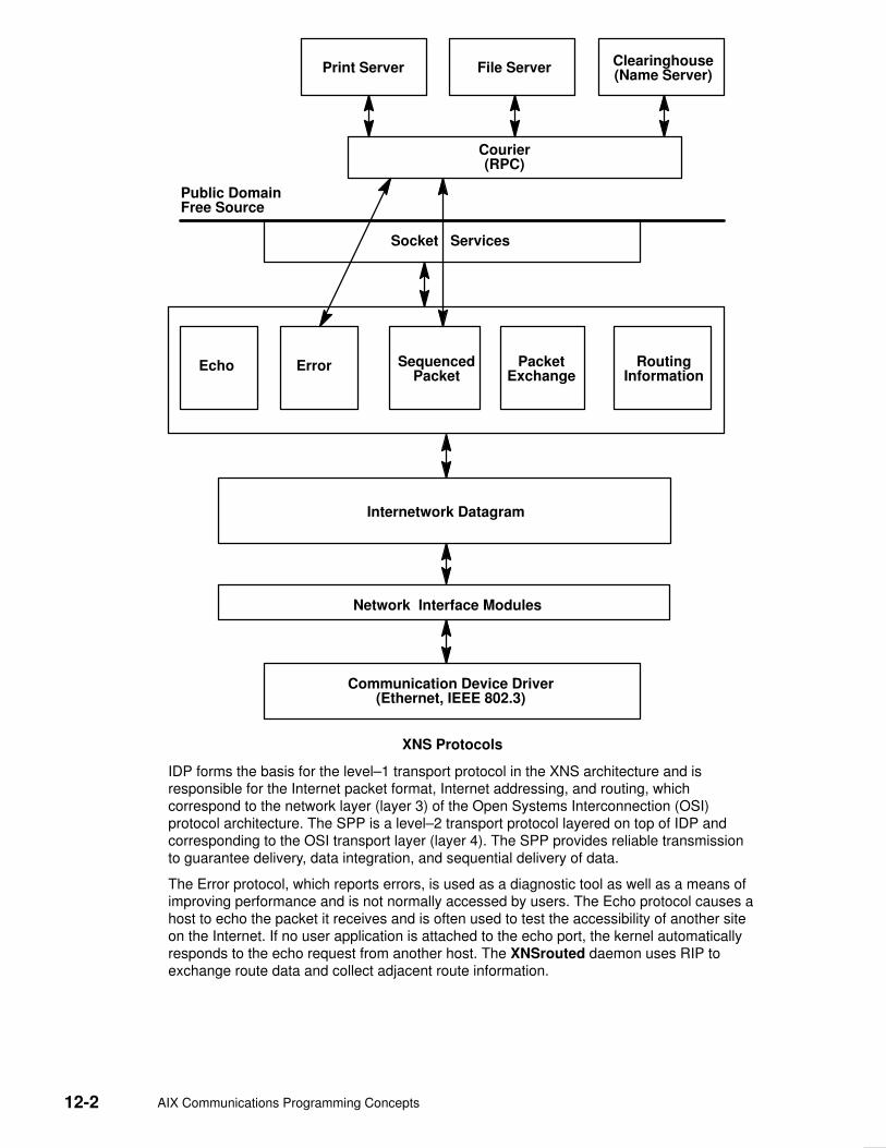
12-2 AIX Communications Programming Concepts
Public DomainFree Source
Courier(RPC)
File Server Clearinghouse(Name Server)
Socket Services
Echo Error SequencedPacket
PacketExchange
RoutingInformation
Communication Device Driver(Ethernet, IEEE 802.3)
Internetwork Datagram
Network Interface Modules
Print Server
XNS Protocols
IDP forms the basis for the level–1 transport protocol in the XNS architecture and isresponsible for the Internet packet format, Internet addressing, and routing, whichcorrespond to the network layer (layer 3) of the Open Systems Interconnection (OSI)protocol architecture. The SPP is a level–2 transport protocol layered on top of IDP andcorresponding to the OSI transport layer (layer 4). The SPP provides reliable transmissionto guarantee delivery, data integration, and sequential delivery of data.
The Error protocol, which reports errors, is used as a diagnostic tool as well as a means ofimproving performance and is not normally accessed by users. The Echo protocol causes ahost to echo the packet it receives and is often used to test the accessibility of another siteon the Internet. If no user application is attached to the echo port, the kernel automaticallyresponds to the echo request from another host. The XNSrouted daemon uses RIP toexchange route data and collect adjacent route information.

Xeros Network Systems 12-3
The SPP is used to support the operation of both stream and sequenced packet socketscreated in the Network Services (NS) domain. The standard datagram service, PEP, isimplemented by a user–level library, using IDP datagram sockets. Raw access to the ErrorProtocol and IDP is possible through raw sockets.
For each SPP– or IDP–based socket, an NS protocol control block is created to hold NSinformation similar to that found in the Internet control block. Also, like the TransmissionControl Protocol (TCP), the SPP creates a control block to hold the protocol stateinformation necessary for its implementation. Unlike those in the Internet domain, the NSprotocol control blocks for all protocols are maintained on one doubly–linked list.
In the NS domain, packet demultiplexing at the network–protocol level is done firstaccording to the network address and port numbers and then according to thecommunication protocol. The linkage between the socket data structures and theprotocol–specific data structures is identical to that found in the Internet communicationdomain.
The SPP uses the spcb parameter as the SPP protocol control block and m parameter asthe memory buffer (mbuf) chain that contains the data to be sent.
All NS protocol input is received by the NS interrupt routine, nsintr, which is invoked atsoftware–interrupt level when a network interface receives a message to be processed byan NS protocol module. The interrupt routine performs consistency checks on the packet,and then determines whether to receive, forward, or discard the packet. If the packet is tobe received, the nsintr routine locates the NS protocol control block for the receiving socketaccording to the sender’s address and the destination port number. The routine then passesthe packet to the receiving protocol.
The SPP and IDP pr_ctloutput routines provide access to NS–specific options that controlthe behavior of the SPP and IDP in processing data transmitted and received through asocket. The following options are usable with both SPP and IDP protocols:
SO_HEADERS_ON_INPUT Returns protocol headers on each message with data.
SO_MTU Sets the maximum size of a message that is sent orreceived.
SO_DEFAULT_HEADERS Establishes a default header for outgoing messages.
System Configuration Two separate network interfaces for the XNS protocol can be implemented, the IEEE 802.3Ethernet interface and the Standard Ethernet interface, which both run on 10Mbps Ethernethardware. The host ID in the XNS address uses the Ethernet address. Multiple Ethernethardware interfaces are supported in the same system. However, to simplify the design, onehost ID for each Ethernet interface is used. Even though multiple host IDs are used in thesame system, packets destined for a specific host ID are received and processedaccordingly.
The ifconfig command configures the network interface for XNS either during run time or atsystem startup. If the interface is configured at system startup, the /etc/rc.net file needs tobe edited to include the ifconfig command. The netns kernel extension is loaded into thesystem when the first XNS network interface is configured.
Note: Since multiple hosts are supported, the host ID should be specified each time anetwork interface is configured.
The following ifconfig command syntax:
ifconfig en0 ns 010:20.5.8.9c.3e.56
configures Ethernet interface en0 on network 010 at host 20.5.8.9c.3e.56.

12-4 AIX Communications Programming Concepts
Routing If your environment allows access to networks not directly attached to your host, you needto set up a routing table to properly route packets. Two schemes are supported by thesystem.
• The first scheme employs the XNSrouted routing–table management daemon tomaintain the system routing tables. The routing daemon accepts the Routing InformationProtocol (RIP) datagram from the network and maintains up–to–date routing tableinformation in a cluster of local area networks. The XNSrouted daemon also has anoption to broadcast the routing table information to all attached hosts. The XNSquerycommand obtains routing table information from a router. The returned informationincludes reachable networks for that particular router and the number of required hops ormetrics.
• The second approach is to define a route to a smart gateway or router, using the routecommand. This requires maintenance of the routing table. For example:
route add –xns 20 10:2.3.45.6.9a.4f
adds a routing entry for network 20 through the host 2.3.45.6.9a.4f on network 10.
It is possible to combine both of the above facilities, allowing you to update the routing tablemanually with the route command and automatically with the XNSrouted daemon. Use thenetstat command to display routing table contents as well as various routing–orientedstatistics. For example:
netstat –r
displays the contents of the routing tables.
The current implementation of XNS automatically forwards all incoming XNS Internetpackets to the appropriate router or network, as long as the packet is not destined for thelocal host and the destination network information is maintained in the routing table.Indirectly, the local host can be used as a router.
XNS Addresses An XNS address occupies 12 bytes and is comprised of three parts:
• A 32–bit network ID
• A 48–bit host ID
• A 16–bit port number
The host ID is an absolute number that must be unique to all XNS Internets. The AIXimplementation uses the 48–bit Ethernet address as host ID. With unique host IDs, thenetwork ID is redundant but is required for routing purposes.
XNS addresses can be represented by several means, as can be seen in the followingexamples:
• 123#9.89.3c.90.45.56
• 5–124#123–456–900–455–749
• 0x45:0x9893c9045569:90
• 0456:9893c9045569H
The first example is in decimal format, and the second example, using – (minus signs), isseparated into groups of three digits each. The 0x and H examples are in hex format.Finally, the 0 in front of the last example indicates that the number preceding the colon is inoctal format.

Xeros Network Systems 12-5
Network Systems Protocol Family The Network Systems (NS) protocol family is a collection of protocols layered atop theInternet Datagram Protocol (IDP) transport layer, using the Xerox Network Systems (XNS)address formats. The NS family provides protocol support for the following socket types:
• SOCK_SEQPACKET
• SOCK_STREAM
• SOCK_DGRAM
• SOCK_RAW
The SOCK_RAW interface is a debugging tool, allowing you to trace all packets entering(or, with a toggling kernel variable, leaving) the local host.
Usage ConventionsThe following conventions apply when using the NS protocols:
• Options NS
• Options NSIP (Network Services Internet Protocol)
• Pseudo–device NS
AddressingNS addresses are 12–byte quantities consisting of a four–byte network number, a six–bytehost number and a two–byte port number, all stored in standard network format. For VAXarchitecture, these are word– and byte–reversed; for Sun systems, they are not reversed.The netns/ns.h file defines the NS address as a structure containing unions (for quickercomparisons).
Sockets in the Internet Protocol (IP) family use the following addressing structure:
struct sockaddr_ns {
short sns–family;
struct ns_addr sns–addr;
char sns_zero[2];
};
where an ns_addr is composed as follows:
union ns_host {
u_char c_host[6];
u_short s_host[3];
};
union ns_net {
u_char c_net[4];
u_short s_net[2];
};
struct ns_addr {
union ns_net x_net;
union ns_host x_host;
u_short x_port;
};

12-6 AIX Communications Programming Concepts
Sockets may be created with an address of all zeros to effect wildcard matching onincoming messages. The local port address specified in a bind subroutine is restricted to begreater than the NSPORT_RESERVED parameter (equals 3000, in the netns/ns.h file)unless the creating process is running as the root user, providing a space of protected portnumbers.
ProtocolsThe NS protocol family comprises the Internet Datagram Protocol (IDP), Error Protocol(available through IDP), and Sequenced Packet Protocol (SPP).
SPP is used to support the SOCK_STREAM and SOCK_SEQPACKET socket types, whileIDP is used to support the SOCK_DGRAM socket type. If no user application is bound tothe echo port, the kernel responds to the Error Protocol by handling and reporting errors inprotocol processing.
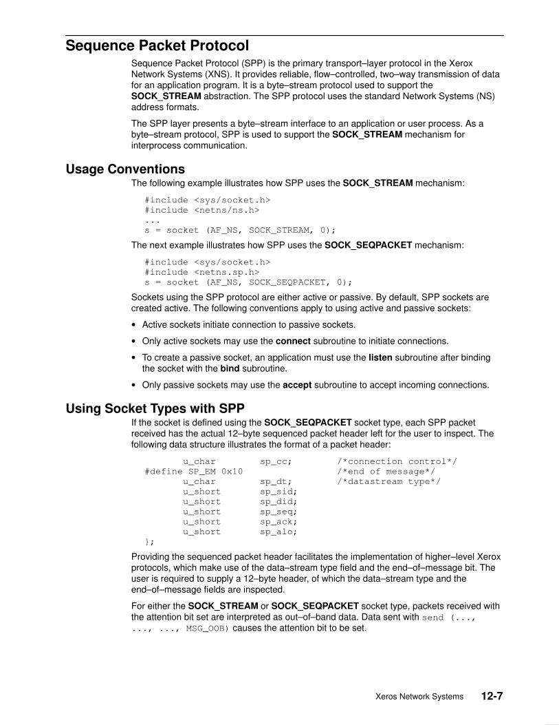
Xeros Network Systems 12-7
Sequence Packet Protocol Sequence Packet Protocol (SPP) is the primary transport–layer protocol in the XeroxNetwork Systems (XNS). It provides reliable, flow–controlled, two–way transmission of datafor an application program. It is a byte–stream protocol used to support theSOCK_STREAM abstraction. The SPP protocol uses the standard Network Systems (NS)address formats.
The SPP layer presents a byte–stream interface to an application or user process. As abyte–stream protocol, SPP is used to support the SOCK_STREAM mechanism forinterprocess communication.
Usage Conventions The following example illustrates how SPP uses the SOCK_STREAM mechanism:
#include <sys/socket.h>
#include <netns/ns.h>
...
s = socket (AF_NS, SOCK_STREAM, 0);
The next example illustrates how SPP uses the SOCK_SEQPACKET mechanism:
#include <sys/socket.h>
#include <netns.sp.h>
s = socket (AF_NS, SOCK_SEQPACKET, 0);
Sockets using the SPP protocol are either active or passive. By default, SPP sockets arecreated active. The following conventions apply to using active and passive sockets:
• Active sockets initiate connection to passive sockets.
• Only active sockets may use the connect subroutine to initiate connections.
• To create a passive socket, an application must use the listen subroutine after bindingthe socket with the bind subroutine.
• Only passive sockets may use the accept subroutine to accept incoming connections.
Using Socket Types with SPP If the socket is defined using the SOCK_SEQPACKET socket type, each SPP packetreceived has the actual 12–byte sequenced packet header left for the user to inspect. Thefollowing data structure illustrates the format of a packet header:
u_char sp_cc; /*connection control*/
#define SP_EM 0x10 /*end of message*/
u_char sp_dt; /*datastream type*/
u_short sp_sid;
u_short sp_did;
u_short sp_seq;
u_short sp_ack;
u_short sp_alo;
};
Providing the sequenced packet header facilitates the implementation of higher–level Xeroxprotocols, which make use of the data–stream type field and the end–of–message bit. Theuser is required to supply a 12–byte header, of which the data–stream type and theend–of–message fields are inspected.
For either the SOCK_STREAM or SOCK_SEQPACKET socket type, packets received withthe attention bit set are interpreted as out–of–band data. Data sent with send (...,..., ..., MSG_OOB) causes the attention bit to be set.

12-8 AIX Communications Programming Concepts
Socket Options for SPP
SO_DEFAULT_HEADERS Determines the data–stream type and whether theend–of–message bit is to be set on every ensuing packet.
SO_MTU Specifies the maximum amount of user data in a singlepacket. The default is 576 bytes minus the size of thepacket header. This quantity affects windowing. Increasingthe mtu parameter without increasing the amount ofbuffering in the socket lowers the number of acceptedunread packets. Anything larger than the default is notforwarded by a genuine XEROX–product internetworkrouter. The data argument for the setsockopt subroutinemust be an unsigned short.
Error Codes SPP fails if one or more of the following are true:
EISCONN The socket already has a connection established on it.
ENOBUFS The system ran out of memory for an internal datastructure.
ETIMEDOUT A connection was dropped due to excessiveretransmissions.
ECONNRESET The remote peer forced the connection to be closed.
ECONNREFUSED The remote peer actively refused connection establishment(usually because no process is listening to the port).
EADDRINUSE An attempt was made to create a socket with a port thathas already been allocated.
EADDRNOTAVAIL An attempt was made to create a socket with a networkaddress for which no network interface exists.

Xeros Network Systems 12-9
nsip Interface The nsip interface enables a user process to encapsulate Network Services (NS) packets inInternet Protocol (IP) packets. This interface is a software mechanism that can be used totransmit Xerox Network Systems (XNS) packets through Internet networks. It functions byprepending an IP header and resubmitting the packet to the UNIX IP machinery.
The root user can advise the operating system of a partner system by naming an IP addressto be associated with an NS address. Presently, only specific host pairs are allowed, and foreach host pair, an artificial point–to–point interface is constructed.
Usage ConventionsThe nsip interface uses the following conventions for encapsulation:
Specifically, a socket option of SO_NSIP_ROUTE is set on a socket of family AF_NS, typeSOCK_DGRAM, passing the following data structure:
struct nsip_req{
struct sockaddr rq_ns; /*must be ns format destination */
struct sockaddr rq_ip; /*must be ip format gateway */
short rq_flags;
};
Error CodesThe nsip mechanism fails if one or more of the following are true:
ENOBUFS The system ran out of memory for an internal data structure.
EADDRNOTAVAIL An attempt was made to create a socket with a network addressfor which no network interface exists.
ENETUNREACH No route to the destination network exists.
EINVAL Unsupported options are specified.
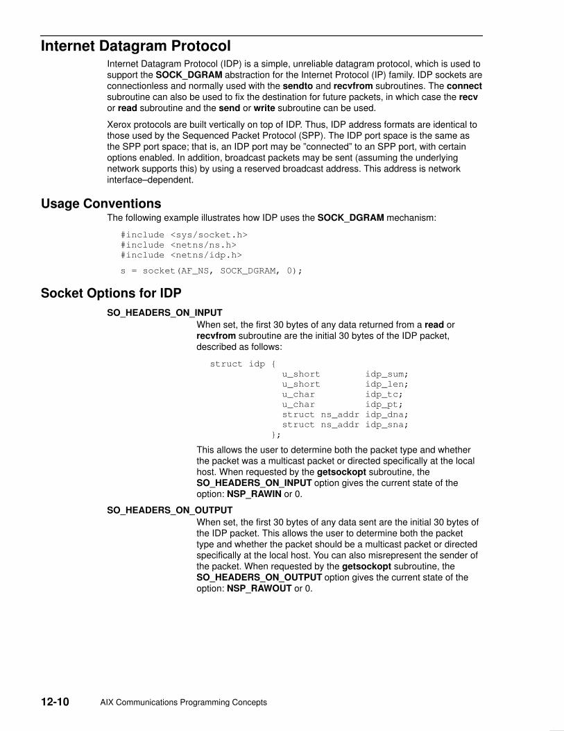
12-10 AIX Communications Programming Concepts
Internet Datagram Protocol Internet Datagram Protocol (IDP) is a simple, unreliable datagram protocol, which is used tosupport the SOCK_DGRAM abstraction for the Internet Protocol (IP) family. IDP sockets areconnectionless and normally used with the sendto and recvfrom subroutines. The connectsubroutine can also be used to fix the destination for future packets, in which case the recvor read subroutine and the send or write subroutine can be used.
Xerox protocols are built vertically on top of IDP. Thus, IDP address formats are identical tothose used by the Sequenced Packet Protocol (SPP). The IDP port space is the same asthe SPP port space; that is, an IDP port may be ”connected” to an SPP port, with certainoptions enabled. In addition, broadcast packets may be sent (assuming the underlyingnetwork supports this) by using a reserved broadcast address. This address is networkinterface–dependent.
Usage ConventionsThe following example illustrates how IDP uses the SOCK_DGRAM mechanism:
#include <sys/socket.h>
#include <netns/ns.h>
#include <netns/idp.h>
s = socket(AF_NS, SOCK_DGRAM, 0);
Socket Options for IDP
SO_HEADERS_ON_INPUT
When set, the first 30 bytes of any data returned from a read orrecvfrom subroutine are the initial 30 bytes of the IDP packet,described as follows:
struct idp {
u_short idp_sum;
u_short idp_len;
u_char idp_tc;
u_char idp_pt;
struct ns_addr idp_dna;
struct ns_addr idp_sna;
};
This allows the user to determine both the packet type and whetherthe packet was a multicast packet or directed specifically at the localhost. When requested by the getsockopt subroutine, theSO_HEADERS_ON_INPUT option gives the current state of theoption: NSP_RAWIN or 0.
SO_HEADERS_ON_OUTPUT
When set, the first 30 bytes of any data sent are the initial 30 bytes ofthe IDP packet. This allows the user to determine both the packettype and whether the packet should be a multicast packet or directedspecifically at the local host. You can also misrepresent the sender ofthe packet. When requested by the getsockopt subroutine, theSO_HEADERS_ON_OUTPUT option gives the current state of theoption: NSP_RAWOUT or 0.

Xeros Network Systems 12-11
SO_DEFAULT_HEADERS
The user provides the kernel an IDP header, from which the kerneldetermines the packet type. When the SO_DEFAULT_HEADERSoption is requested by the getsockopt subroutine, the kernelprovides an IDP header, showing the default packet type and thelocal and foreign addresses, if connected.
SO_ALL_PACKETS
When set, this option disables automatic processing of both ErrorProtocol packets, and SPP packets.
SO_SEQNO When requested by the getsockopt subroutine, the S0_SEQNOoption returns a sequence number that is not likely to be repeated. Itis useful in constructing Packet Exchange Protocol (PEP) packets.
Error CodesThe IDP protocol fails if one or more of the following are true:
EISCONN The socket already has a connection established on it.
ENOBUFS The system ran out of memory for an internal data structure.
ENOTCONN The socket has not been connected or no destination address wasspecified when the datagram was sent.
EADDRINUSE An attempt was made to create a socket with a port that has alreadybeen allocated.
EADDRNOTAVAIL An attempt was made to create a socket with a network address forwhich no network interface exists.

12-12 AIX Communications Programming Concepts

X-1Index
Index
Numbers64–bit user processes, modules, 10-33
Aaddresses
binding, 9-19NDD, 9-13obtaining, 9-20Socket
data structures, 9-8families, 9-9
storage, 9-12TCP/IP, 9-12translation, 9-31, 9-34
agent (SNMP), 7-11array data type (XDR), 4-13arrays
XDR, 4-35XDR filter primitive, 4-22
authentication, 8-10DES, RPC, 8-12, 8-44NULL (RPC), 8-11UNIX (RPC), 8-11, 8-41
Bbatching (RPC), 8-26binding, Sockets, 9-19binding processes (RPC), 8-4boolean
data type (XDR), 4-10RPC, 4-10
booleans, RPC, 8-32broadcasting (RPC), 8-27, 8-57
server side, 8-35byte–order translation, 9-34
CC preprocessor (RPC), 8-34callback, RPC, 8-62callback procedures, RPC, 8-27canonical data representation (XDR), 4-2client routines, 5-2clients
agent, 5-3, 5-5binding, 8-4
clocks, 8-13communications domains (Sockets), 9-9connections (Sockets), 9-21constants
RPC language, 8-30XDR language, 4-15
conversion routines, 5-2
Ddata description, 4-30data link control, 1-3data representation, canonical, 4-2
data streams (XDR), 4-24data transfer, (Sockets), 9-25data types, passing, 8-54data types (XDR), 4-9database, MIB, 7-8database manager, 3-2datagram services, connectionless, 9-23DBM
NDBM equivalents, 3-2subroutines, 3-2
DCL8023 (IEEE 802.3 Ethernet data link control),1-34
declarationsRPC language, 8-31XDR language, 4-7
DES, authentication, RPC, 8-15, 8-44DES authentication
protocol, 8-14RPC, 8-12
Diffie–Hellman encryption, 8-15discriminated union, example, 4-15discriminated union (XDR)
example, 4-37XDR, 4-15
DLC (data link control), 1-16, 1-34, 1-50, 1-67device manager environment
components, 1-4multiuser configuration, 1-4structure, 1-3
error logging facility, 1-12generic, 1-3programming procedures, 1-14qualified logical link control, 1-79reference information, 1-14
DLC_ENABLE_SAP, 1-30DLC8023
programming interfaces, 1-46protocol support, 1-38
data packet, 1-38response modes, 1-38station types, 1-38
DLC8023 (IEEE 802.3 Ethernet data link control)connection contention, 1-44direct network services, 1-43link sessions
initializing, 1-45terminating, 1-45
name–discovery services, 1-40overview, 1-34
DLC8023 device managerfunctions, 1-37nodes, 1-35
DLCETHER (standard Ethernet data link control),1-50
connection contention, 1-60device manager functions, 1-53device manager nodes, 1-51direct network services, 1-59

X-2 Communications Programming Concepts
link sessionsinitiating, 1-61terminating, 1-62
name–discovery services, 1-56overview, 1-50programming interfaces, 1-63protocol support, 1-54
DLCQLLC device manager, 1-79DLCTOKEN, device manager
ADM and ABME modes, 1-17functions of, 1-19introduction, 1-16
DLCTOKEN (token–ring data link control), 1-16connection contention, 1-26device manager functions, 1-19device manager nodes, 1-17direct network services, 1-25initiating link sessions, 1-27name–discovery services, 1-22programming interfaces, 1-29protocol support
data packet, 1-20response modes, 1-20station types, 1-20
driversconfiguring, in PSE, 10-37STREAMS, 10-32
Eenumeration data type (XDR), 4-10enumerations
RPC language, 8-30XDR language, 4-7
error logging, SMUX example subroutines, 7-16example, XDR, 4-34eXternal Data Representation, 4-2
FFDDIDLC
connection contention, 1-96device manager functions, 1-89device manager nodes, 1-87device protocol support, 1-90direct network services, 1-95initiating link sessions, 1-97name–discovery services, 1-92programming interfaces, 1-98
Fiber Distributed Data Interface, 1-86filter primitives
basic, 4-20constructed, 4-21
floating–point data types (XDR), 4-10Flow Control, STREAMS, 10-9
GGDLC, overview, 1-3GDLC (generic data link control)
criteria, 1-5interface, implementing, 1-6ioctl operations, 1-7kernel services, 1-10problem determination
error logs, 1-12
link station trace, 1-12overview, 1-11
status information, 1-11
Hhandles, RPC, 8-38header files, Sockets, 9-7, 9-41highest layer, RPC, 8-21
II/O modes, sockets, 9-27IDP, 12-10
conventions, 12-10error codes, 12-11overview, 12-10Socket options, 12-10
idsocket, 9-24include files, Sockets, 9-7integer data type (XDR), 4-9interface (Sockets), 9-4, 9-5intermediate layer, 8-22
RPC, 8-48internet datagram protocol, 12-10internet protocol, multicasts, 9-29intrinsic functions, list of, 7-13ioctl operations
Sockets, 9-16STREAMS, 10-22
Llanguage (RPC), 8-28language specifications (XDR), 4-6libraries
RPC run–time, 5-2XDR, 4-5, 4-18
librarySockets, 9-6XDR, 4-20
link station, 1-8linked lists (XDR), 4-27links
testing, 1-8tracing, 1-8
LLC, 1-17, 1-19local–busy mode, 1-8location broker
client agent, 5-3, 5-5components, 5-3daemons, 5-3global, 5-6local, 5-6overview, 5-3
log device driver, 10-35, 10-36lowest layer, RPC, 8-24LS
definition, 1-8statistics, querying, 1-9
LS (link station)terminating a DLCTOKEN session, 1-28trace facilities, channels, 1-13trace facility
entries, 1-13reports, 1-13

X-3Index
using with DLCTOKEN, 1-27
MMAC, 1-19Management Information Base, 7-3memory, allocating, 8-24message, sending, 9-29messages
blocks, 10-25RPC, 8-9streams, 10-25
MIBdatabase, 7-8overview, 7-3variables, 7-6, 7-7
model (RPC), 8-3modules, 10-24
64–bit support, 10-33configuring (PSE), 10-37introduction to streams, 10-4user–context, 10-32
monitors, SNMP, 7-10multiprogram versions, RPC, 8-56
NNCS, 5-2NDBM
DBM equivalents, 3-2subroutines, 3-2
NDDprotocols, 9-13socket addresses, 9-13
NDMB, problem diagnosis, 3-1Network Computing System, 5-1Network Information Service, 6-2Network Management
SNMP, 7-1xgmon, 7-1
NISfiles, 6-2subroutines, 6-2
non–filter primitives, list, 4-24nonfilter primitives, list, 4-19NS (Network Systems), 12-5NS protocol interface, 12-9NS protocols, 12-1nsip
conventions, 12-9error codes, 12-9packets, 12-9
Oopaque data type, RPC, 8-33opaque data types, XDR, 4-12optional data types (XDR), 4-16options, socket, 9-24options, sockets, 9-24out–of–band data, 9-25
Ppassing linked lists (XDR), example, 4-27ping program (RPC), 8-66pointers, XDR, 4-38
port mapper, 8-16Portable Streams Environment, 10-37ports, registering (RPC), 8-16primitives
filter, 4-20non–filter, 4-24nonfilter, 4-19
procedure numbers, list of, 8-20procedure numbers (RPC), assigning, 8-20program numbers, assigning (RPC), 8-19protocol
RPC, port mapper, 8-17Sockets, 9-17, 9-41XNS
IDP, 12-10SPP, 12-7
protocol compilers, rpcgen, 8-34protocols
nsip, 12-9RPC, 8-4, 8-5
authentication, 8-10specifications, 8-20
PSE, 10-37put procedures, Streams, 10-29
QQLLC (Qualified Logical Link Control) DLC
describing programming interfaces, 1-80device manager, 1-79overview, 1-79
QLLC (qualified logical link control) DLC,describing device manager functions, 1-79
qualified logical link control, 1-79QUEUES, processing messages with STREAMS,
10-29
Rrecords, RPC messages, 8-9Remote Procedure Call (RPC)
highest layer, 8-21lowest layer, 8-24
remote procedure calls, 5-2, 8-1RPC
arbitrary data types, passing, 8-54authentication, 8-10
client side, 8-11DES overview, 8-12DES protocol, 8-14server side, 8-12
batching, 8-26binding process, 8-4broadcasting, 8-57
protocols, 8-27server side, 8-35
C preprocessor, 8-34callback, 8-62
procedures, 8-27constants, 8-30converting local procedures, 8-67
overview, 8-34declarations, 8-31enumerations, 8-30examples, list of, 8-37

X-4 Communications Programming Concepts
features, 8-26generating XDR routines, 8-72
overview, 8-34intermediate layer, 8-48language, 8-28macros, 8-37message protocol, 8-5message replies, 8-7messages, 8-5model, 8-3multiple program versions, 8-56overview, 8-1port mapper, 8-16programming, 8-19programs, list of, 8-20rpc process (TCP), 8-59rpcgen protocol compiler, 8-34select subroutine, 8-58
on the server side, 8-27semantics, 8-4server procedures, 8-36starting, from inetd daemon, 8-25structures, 8-29subroutines, 8-37timeouts, changing, 8-35transports, 8-4type definitions, 8-30unions, 8-29XDR, using with, 4-5
RPC (Remote Procedure Call)arbitrary data types, passing, 8-23intermediate layer, 8-22marking records in messages, 8-9
RPC authenticationDES, 8-44
clock synchronization, 8-13Diffie–Hellman encryption, 8-15naming scheme, 8-12nicknames, 8-13on the client side, 8-13on the server side, 8-13verifiers, 8-12
NULL, 8-11overview, 8-10protocol, 8-10UNIX, 8-41
overview, 8-11RPC example programs
generating XDR routines, 8-72ping program, 8-66select subroutine, 8-58UNIX authentication, 8-41
RPC languageconstants, 8-30declarations, 8-31definitions, 8-28descriptions, 8-28enumerations, 8-30exceptions to rules
booleans, 8-32opaque data, 8-33strings, 8-33voids, 8-33
overview, 8-28
ping program, 8-66programs, syntax, 8-30rpcgen protocol compiler, 8-34structures, 8-29syntax requirements for program definition,
8-32type definitions, 8-30unions, 8-29
RPC layershighest, 8-47intermediate
handling arbitrary data structures, 8-22routines, 8-22
lowest, 8-50RPC messages
calls, 8-6protocol requirements, 8-5replies, 8-7structures, 8-5
RPC port mapperoverview, 8-16procedures, 8-18protocol, 8-17registering ports with, 8-16
rpc process (RPC), on TCP, 8-59RPC programming
procedure numbers, 8-20program numbers, 8-19version numbers, 8-20
RPC programscompiling, 8-25linking, 8-25list of, 8-20syntax, 8-30
RPC runtime libraryNCS, 5-2routines
client, 5-2conversion, 5-2server, 5-2
rpcgen protocol compilerbroadcasting, server side, 8-35C preprocessor, 8-34changing timeouts, 8-35converting local procedures, 8-34, 8-67generating XDR routines, 8-34, 8-72other information passed to server, 8-36overview, 8-34
RPCL, 8-32
SSAP
definition, 1-7statistics, querying, 1-9
SDLC, 1-67SDLC (Synchronous Data Link Control) DLC,
initiating asynchronous function subroutine calls,1-78
SDLC (synchronous data link control) DLCdevice manager functions, 1-68programming interfaces, 1-73providing protocol support, 1-69

X-5Index
select subroutines (RPC), 8-58overview, 8-27
semantics (RPC), 8-4sending messages, 9-29server procedures (RPC), 8-36servers, RPC routines and, 5-2service access point, 1-7service procedures, STREAMS, 10-29short–hold mode, 1-8shutdown sockets, 9-28simple network management protocol, 7-2SMUX subroutines, 7-14
adios, 7-16advise, 7-17
SNMPagent, 7-11database, 7-3monitor, 7-10overview, 7-2traps, 7-12
SNMP multiplexer (SMUX), 7-16socket
binding, 9-12communication domains, 9-9
Socketsoptions, get, set, 9-24overview, 9-2
sockets, 9-12accepting internet Streams connections, 9-48accepting UNIX Stream connections, 9-53address translation, 9-31atm socket pvc client, sending data, 9-54atm socket pvc server, receiving data, 9-56atm socket svc client, sending data, 9-66atm socket svc server, receiving data, 9-69atm sockets rate–enforced svc client, sending
data, 9-58binding addresses, 9-19binding names, 9-19blocking mode, 9-27checking pending connections, 9-50closing, 9-28connecting, 9-3connectionless, 9-23connections, 9-21creating, 9-3, 9-18data structures, 9-8data transfer, 9-3, 9-25ethernet
receiving packets, 9-72sending packets, 9-74
examples, understanding, 9-38header files, 9-7, 9-41I/O modes, 9-27interface, 9-4, 9-5internet datagrams
reading, 9-43sending, 9-44
Internet Stream, initiating, 9-47kernel services, list of, 9-39layer, 9-4library, 9-6
subroutines, 9-39
namesbinding, 9-19host, 9-33network, 9-33protocol, 9-34resolution, 9-36service, 9-34translation, 9-35
network packets, analyzing, 9-77out–of–band data, 9-25protocols, 9-17, 9-41server connections, 9-21shutdown, 9-28socketpair subroutine, 9-42types, 9-15UNIX datagrams
reading, 9-45sending, 9-46
UNIX Stream connections, 9-52XDR, 4-34
SPP (Sequence Packet Protocol), 12-7conventions, 12-7error codes, 12-8overview, 12-7socket options, 12-8socket types, 12-7
standard Ethernet data link control, 1-50statistics, querying
LS, 1-9SAP, 1-9
stream end, 10-5stream head, 10-3STREAMS
asynchronous protocol example, 10-40building, 10-23commands, 10-48
configuring, 10-48maintaining, 10-48
definition, 10-2differences between PSE and V.4, 10-46drivers
introduction, 10-32list of, 10-49
Flow Control, 10-9functions, list of, 10-50ioctl operations, 10-18log device driver, 10-35, 10-36message queue, 10-27messages, 10-25
allocation, 10-26sending and receiving, 10-28types, 10-26
modules, 10-4, 10-8, 10-32list of, 10-49
overview, 10-1protocol substitution, 10-8PSE, 10-37pushable modules, 10-24put procedures, 10-29QUEUE procedures, 10-29queues, 10-27service procedures, 10-29stream end, 10-5

X-6 Communications Programming Concepts
stream head, 10-3streamio operations, 10-22subroutines, 10-18
list of, 10-49synchronization, 10-11system calls, 10-18
list of, 10-50tunable parameters, 10-19understanding flow control, 10-9utilities, list of, 10-50welding mechanism, 10-15
streams, TLI, 10-52strings
RPC, 8-33XDR, 4-13
structuresRPC language, 8-29XDR language, 4-7, 4-14
subroutine format (XDR), 4-4Synchronous Data Link Control, 1-67
TTCP/IP
list of RFCs, 11-3programming references
list of files and file formats, 11-2list of methods, 11-2
socket addresses, 9-12timeouts, changing (RPC), 8-35token–ring data link control, 1-16Transmission Control Protocol/Internet Protocol,
11-1transport protocol, and RPC, 8-4transport service library interface, TLI, 10-52traps, 7-12type definitions
RPC language, 8-30XDR language, 4-16
UUnderstanding STREAMS Flow Control, 10-9unions
discriminated, 4-15optional data, 4-16RPC language, 8-29XDR language, 4-7
UNIX authentication (RPC), 8-11, 8-41
VV.4 STREAMS, differences between and, 10-46version numbers, assigning (RPC), 8-20voids
RPC, 8-33XDR, 4-15
XXDR
canonical data representation, 4-2
data streams, 4-24data types, 4-9filter primitives, 4-20, 4-21generating routines with RPC, 8-34language, specifications, 4-6library, 4-5memory allocation (RPC), 8-24non–filter primitives, 4-24overview, 4-2primitives, 4-20programming reference library, 4-18remote procedure calls and, 8-1RPC, generating routines with, 8-72RPC, using with, 4-5structures, 4-14subroutine format, 4-4type definitions, 4-16unions, optional data, 4-16unsupported representations, 4-3using rpc process with, 8-59
XDR (eXternal Data Representation), unions,discriminated, 4-15
XDR examplearray, 4-35data description, 4-30discriminated unions, 4-37justification for using, 4-32linked lists, 4-27pointers, 4-38
XDR languageblock size, 4-3declarations, 4-7enumerations, 4-7lexical notes, 4-6structures, 4-7syntax notes, 4-8unions, 4-7
XNSaddresses, 12-4configuring, 12-3nsip interface, 12-9protocol family, 12-5protocols
addressing, 12-5relationships between, 12-1usage convention, 12-5
routing with, 12-4XNS protocols
IDP (Internet Datagram Protocols), 12-10nsip (NS Internet Protocol), interface, 12-9relationships between, 12-1SPP (Sequence Packet Protocol), 12-7
XTI, 10-52

Vos remarques sur ce document / Technical publication remark form
Titre / Title : Bull AIX Communications Programming Concepts
Nº Reférence / Reference Nº : 86 A2 35JX 01 Daté / Dated : December 1998
ERREURS DETECTEES / ERRORS IN PUBLICATION
AMELIORATIONS SUGGEREES / SUGGESTIONS FOR IMPROVEMENT TO PUBLICATION
Vos remarques et suggestions seront examinées attentivement.
Si vous désirez une réponse écrite, veuillez indiquer ci-après votre adresse postale complète.
Your comments will be promptly investigated by qualified technical personnel and action will be taken as required.
If you require a written reply, please furnish your complete mailing address below.
NOM / NAME : Date :
SOCIETE / COMPANY :
ADRESSE / ADDRESS :
Remettez cet imprimé à un responsable BULL ou envoyez-le directement à :
Please give this technical publication remark form to your BULL representative or mail to:
BULL ELECTRONICS ANGERS
CEDOC
34 Rue du Nid de Pie – BP 428
49004 ANGERS CEDEX 01
FRANCE

Technical Publications Ordering Form
Bon de Commande de Documents Techniques
To order additional publications, please fill up a copy of this form and send it via mail to:
Pour commander des documents techniques, remplissez une copie de ce formulaire et envoyez-la à :
BULL ELECTRONICS ANGERSCEDOCATTN / MME DUMOULIN34 Rue du Nid de Pie – BP 42849004 ANGERS CEDEX 01FRANCE
Managers / Gestionnaires :Mrs. / Mme : C. DUMOULIN +33 (0) 2 41 73 76 65Mr. / M : L. CHERUBIN +33 (0) 2 41 73 63 96
FAX : +33 (0) 2 41 73 60 19E–Mail / Courrier Electronique : [email protected]
Or visit our web site at: / Ou visitez notre site web à:
http://www–frec.bull.com (PUBLICATIONS, Technical Literature, Ordering Form)
CEDOC Reference #No Référence CEDOC
QtyQté
CEDOC Reference #No Référence CEDOC
QtyQté
CEDOC Reference #No Référence CEDOC
QtyQté
_ _ _ _ _ _ _ _ _ [ _ _ ] _ _ _ _ _ _ _ _ _ [ _ _ ] _ _ _ _ _ _ _ _ _ [ _ _ ]
_ _ _ _ _ _ _ _ _ [ _ _ ] _ _ _ _ _ _ _ _ _ [ _ _ ] _ _ _ _ _ _ _ _ _ [ _ _ ]
_ _ _ _ _ _ _ _ _ [ _ _ ] _ _ _ _ _ _ _ _ _ [ _ _ ] _ _ _ _ _ _ _ _ _ [ _ _ ]
_ _ _ _ _ _ _ _ _ [ _ _ ] _ _ _ _ _ _ _ _ _ [ _ _ ] _ _ _ _ _ _ _ _ _ [ _ _ ]
_ _ _ _ _ _ _ _ _ [ _ _ ] _ _ _ _ _ _ _ _ _ [ _ _ ] _ _ _ _ _ _ _ _ _ [ _ _ ]
_ _ _ _ _ _ _ _ _ [ _ _ ] _ _ _ _ _ _ _ _ _ [ _ _ ] _ _ _ _ _ _ _ _ _ [ _ _ ]
_ _ _ _ _ _ _ _ _ [ _ _ ] _ _ _ _ _ _ _ _ _ [ _ _ ] _ _ _ _ _ _ _ _ _ [ _ _ ]
[ _ _ ] : no revision number means latest revision / pas de numéro de révision signifie révision la plus récente
NOM / NAME : Date :
SOCIETE / COMPANY :
ADRESSE / ADDRESS :
PHONE / TELEPHONE : FAX :
E–MAIL :
For Bull Subsidiaries / Pour les Filiales Bull :
Identification:
For Bull Affiliated Customers / Pour les Clients Affiliés Bull :
Customer Code / Code Client :
For Bull Internal Customers / Pour les Clients Internes Bull :
Budgetary Section / Section Budgétaire :
For Others / Pour les Autres :
Please ask your Bull representative. / Merci de demander à votre contact Bull.


BULL ELECTRONICS ANGERS
CEDOC
34 Rue du Nid de Pie – BP 428
49004 ANGERS CEDEX 01
FRANCE
86 A2 35JX 01
ORDER REFERENCE
PLA
CE
BA
R C
OD
E I
N L
OW
ER
LE
FT
CO
RN
ER

Utiliser les marques de découpe pour obtenir les étiquettes.
Use the cut marks to get the labels.
86 A2 35JX 01
AIXCommunications
ProgrammingConcepts
86 A2 35JX 01
AIXCommunications
ProgrammingConcepts
86 A2 35JX 01
AIXCommunications
ProgrammingConcepts