Airship Structural Analysis - info.aiaa.org · Lin Liao Aeronautical Engineer, PhD Worldwide Aeros...
22
Airship Structural Analysis Airship Structural Analysis Lin Liao Aeronautical Engineer, PhD Worldwide Aeros Corp., Montebello, CA 1 The Eighth Annual AIAA Southern California Aerospace Systems and Technology (ASAT) Conference Santa Ana, CA, May 21, 2011
Transcript of Airship Structural Analysis - info.aiaa.org · Lin Liao Aeronautical Engineer, PhD Worldwide Aeros...
Airship Structural AnalysisAirship Structural Analysis
Lin LiaoAeronautical Engineer, PhD
Worldwide Aeros Corp., Montebello, CA
1The Eighth Annual AIAA Southern California Aerospace Systems and Technology (ASAT) Conference
Santa Ana, CA, May 21, 2011

Overview
Introduction
Overview
Introduction
Analysis of airshipsRigid body motion analysisRigid body motion analysis
Static bending moment
Aerodynamic bending moment
Envelope stress analysis
Stress analysis of empennage attachment
Cable_truss structures
Summaryy
2The Eighth Annual AIAA Southern California Aerospace Systems and Technology (ASAT) Conference
Santa Ana, CA, May 21, 2011

Introduction
Non‐rigid airships
Introduction
Non rigid airshipsEmpirical experiences
“Airship Design”, “Airship Technology”
Finite Element modeling
NASTRAN,ABAQUS
Rigid airships Bulkhead construction
No FEA model of rigid airships
3The Eighth Annual AIAA Southern California Aerospace Systems and Technology (ASAT) Conference
Santa Ana, CA, May 21, 2011

Vertical & Longitudinal DirectionsVertical & Longitudinal Directions
The Eighth Annual AIAA Southern California Aerospace Systems and Technology (ASAT) ConferenceSanta Ana, CA, May 21, 2011
4

Lateral DirectionLateral Direction
The Eighth Annual AIAA Southern California Aerospace Systems and Technology (ASAT) ConferenceSanta Ana, CA, May 21, 2011
5

( )static air heliumL Vρ ρ= −
Vertical & Longitudinal Directions
Calculation of lift, drag, and pitching moment
Vertical & Longitudinal Directions
2 / 3D LL C V q=2 / 3
DD C V q= y MyM C Vq=
[( / ) ( / ) ]cos cosT emp emp emp emp empL S q dC d dC dα α δ δ θ α= +
Sum of forces and moments in vertical & longitudinal directions
6The Eighth Annual AIAA Southern California Aerospace Systems and Technology (ASAT) Conference
Santa Ana, CA, May 21, 2011

( )static air heliumL Vρ ρ= −
Lateral Direction
Sum of forces and moments in lateral direction
Lateral Direction
7The Eighth Annual AIAA Southern California Aerospace Systems and Technology (ASAT) Conference
Santa Ana, CA, May 21, 2011
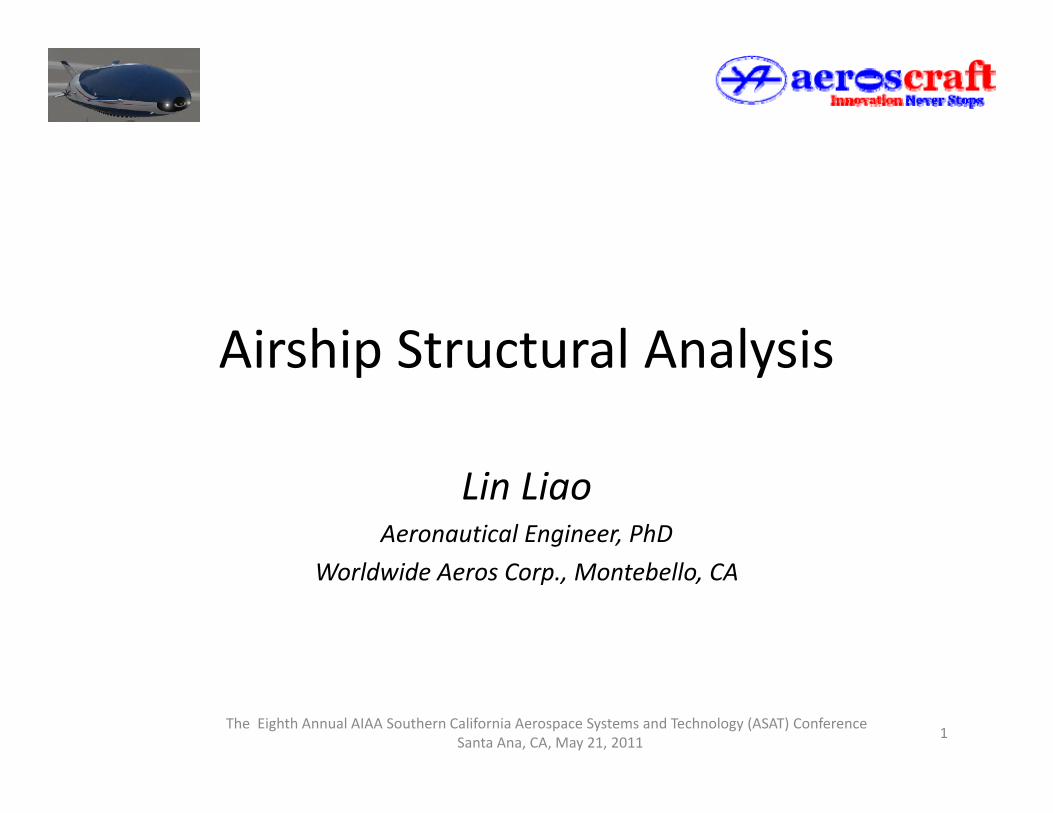
Flight Maneuver ConditionsFlight Maneuver ConditionsCondition Speed Weight Attitude Load Factor and
Acceleration1 Level Flight V W Horizontal n n n =0;χ ø=01 Level Flight VH Wt Horizontal nx ,ny,nz=0;χ,ø=0
2 Level Flight Reverse Thrust N/A N/A N/A N/A
3 Nose Down VH Wo Θ=+30° ny =0;nz>0;χ, ø=04 Nose Up V W Θ= 30° n =0;n <0;χ ø=04 Nose Up VH Wo Θ=-30 ny =0;nz<0;χ, ø=05 Descent & Pull-Up VH Wt Θ<0 ny =0;nz>0;χ,ø=06 Turn Entry VSH Wo Horizontal ny ≠0;ø>07 Turn & Reverse VSH Wo Horizontal ny ≠0;ø<08 Di E t V W H i t l 0 <0 08 Dive Entry VH Wo Horizontal ny =0;χ<0;ø=09 Climb Entry VH Wo Horizontal ny =0;χ>0;ø=010 Turn & Climb VH Wo Horizontal χ>0;ø>011 Turn & Dive VH Wo Horizontal χ<0;ø>012 Turn VSH Wo Horizontal nx ,nz=0;ny<0;χ,ψ=013 Turn Recovery VSH Wo Horizontal nx ,nz=0;ny<0;χ,ψ=014 Turn Rec. & Climb VH Wo Horizontal ny<0;χ>015 Turn Rec. & Dive VH Wo Horizontal ny<0;χ<0
The Eighth Annual AIAA Southern California Aerospace Systems and Technology (ASAT) ConferenceSanta Ana, CA, May 21, 2011
8
o
16 Light Flight VH Wmin Θ<0 ny=0; nz>0; ø=0
Calculation of Static Bending Moment
The envelope is divided into longitudinal segments.Distribution of buoyancy force is obtained by multiplying the segment
Calculation of Static Bending Moment
Distribution of buoyancy force is obtained by multiplying the segmentvolume by the Helium (96% purity as specified by ADC) unit lift. Thebuoyancy forces is given the (+) sign.
The segment envelope weight is obtained in proportion to the segmentsurface area, and given the (-) sign to denote weight downward.
The components (nose cone, helium, etc.) are placed in their nearestsegment, and given the (-) sign.
The segment load F is obtained by summing up the above forces andweights.
The envelope shear at each segment, S, is obtained by summing the aboveF f th t th t h h i d t i dF from the nose up to the segment where shear is determined.
The envelope bending moment at each segment, M, is obtained bysumming the above S multiplied by the segment length, from the nose up tothe segment where bending moment is determined
9The Eighth Annual AIAA Southern California Aerospace Systems and Technology (ASAT) Conference
Santa Ana, CA, May 21, 2011
the segment where bending moment is determined.

Static Bending MomentStatic Bending Moment
10 00012,00014,000
b]
02,0004,0006,0008,000
10,000
ding
Mom
ent [
ft-lb
Case 1Envelope: 30%Car: 55%
-4,000-2,000
00% 10% 20% 30% 40% 50% 60% 70% 80% 90% 100%B
end
Distance Aft of Nose (Percent of Airship Length)Envelope Bending Moment due to Weight & Buoyancy
4 5006,5008,500
10,50012,500
men
t [ft
-lb]
Case 2Envelope: 36%
-3,500-1,500
5002,5004,500
0% 10% 20% 30% 40% 50% 60% 70% 80% 90% 100%Ben
ding
Mom
Di t Aft f N (P t f Ai hi L th)
pCar: 50%
The Eighth Annual AIAA Southern California Aerospace Systems and Technology (ASAT) ConferenceSanta Ana, CA, May 21, 2011
10
Distance Aft of Nose (Percent of Airship Length)
Envelope Bending Moment due to Weight & Buoyancy
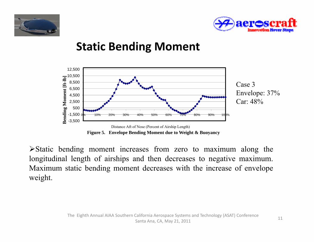
Static Bending MomentStatic Bending Moment
10 50012,500
2,5004,5006,5008,500
10,500
Mom
ent [
ft-lb
]
Case 3Envelope: 37%Car: 48%
-3,500-1,500
5000% 10% 20% 30% 40% 50% 60% 70% 80% 90% 100%
Ben
ding
M
Distance Aft of Nose (Percent of Airship Length)Figure 5. Envelope Bending Moment due to Weight & Buoyancy
Static bending moment increases from zero to maximum along thelongitudinal length of airships and then decreases to negative maximum.M i t ti b di t d ith th i f lMaximum static bending moment decreases with the increase of envelopeweight.
The Eighth Annual AIAA Southern California Aerospace Systems and Technology (ASAT) ConferenceSanta Ana, CA, May 21, 2011
11

Aerodynamic Bending Moment
( ) ( )[ ] 25.002.0max 5.05624.04/129.0 LVolVLDLM ⋅⋅⋅⋅⋅−⋅⋅−+⋅= ∞μρ
Aerodynamic Bending Moment
Aerodyanmic Bending Moment vs Diameter
Gust 1, Gust 2, and Gust 3: 20 ft/s, 25 ft/s, 30 ft/s
360
410
460
t (10
3 lb
-ft)
210
260
310
ng M
omen
t
gust 1gust 2gust 3
160
48 49 50 51 52 53 54 55 56 57Ben
din
Max Diameter (ft)
The Eighth Annual AIAA Southern California Aerospace Systems and Technology (ASAT) ConferenceSanta Ana, CA, May 21, 2011
12
Variation of Aerodynamic Bending Moment with respect to Diameter

Aerodynamic Bending MomentAerodynamic Bending Moment
410
460
b-ft
)
Aerodyanmic Bending Moment vs Length
310
360
410
omen
t (10
3 lb
gust 1
160
210
260
210 220 230 240 250 260 270 280 290 300Ben
ding
Mo gust 2
gust 3
210 220 230 240 250 260 270 280 290 300B
Length (ft)
Variation of Aerodynamic Bending Moment with respect to Length
The Eighth Annual AIAA Southern California Aerospace Systems and Technology (ASAT) ConferenceSanta Ana, CA, May 21, 2011
13
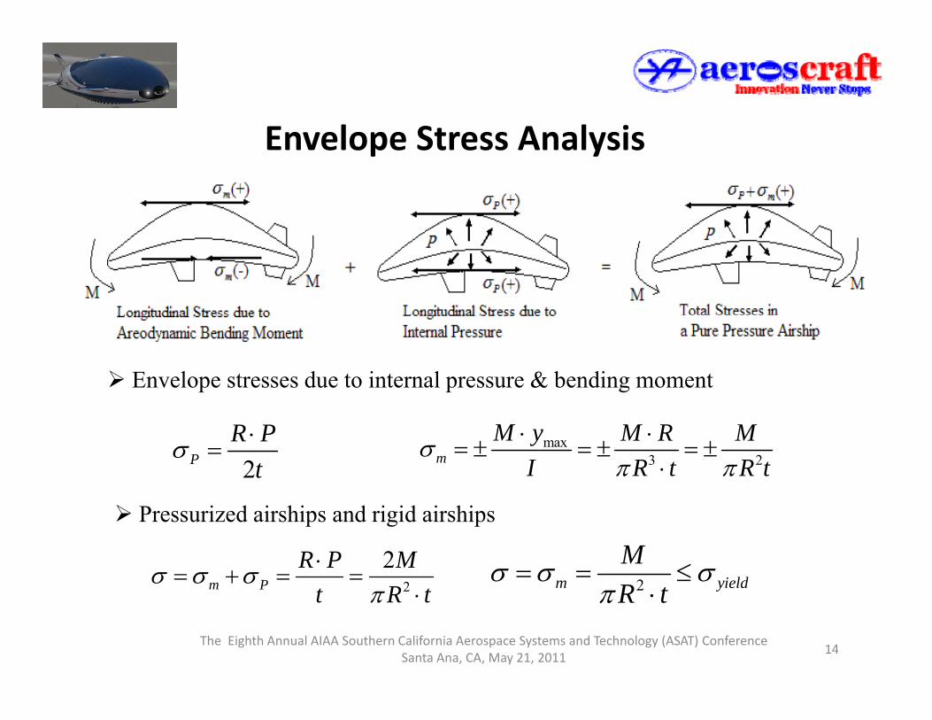
Envelope Stress AnalysisEnvelope Stress Analysis
Envelope stresses due to internal pressure & bending moment
2PR P
tσ ⋅
= max3 2m
M y M R MI R t R t
σπ π
⋅ ⋅= ± = ± = ±
⋅
2
2m P
R P MR
σ σ σ ⋅= + = = 2m yield
MR t
σ σ σ= = ≤
Pressurized airships and rigid airships
The Eighth Annual AIAA Southern California Aerospace Systems and Technology (ASAT) ConferenceSanta Ana, CA, May 21, 2011
14
2m P t R tπ ⋅ 2m yieldR tπ ⋅
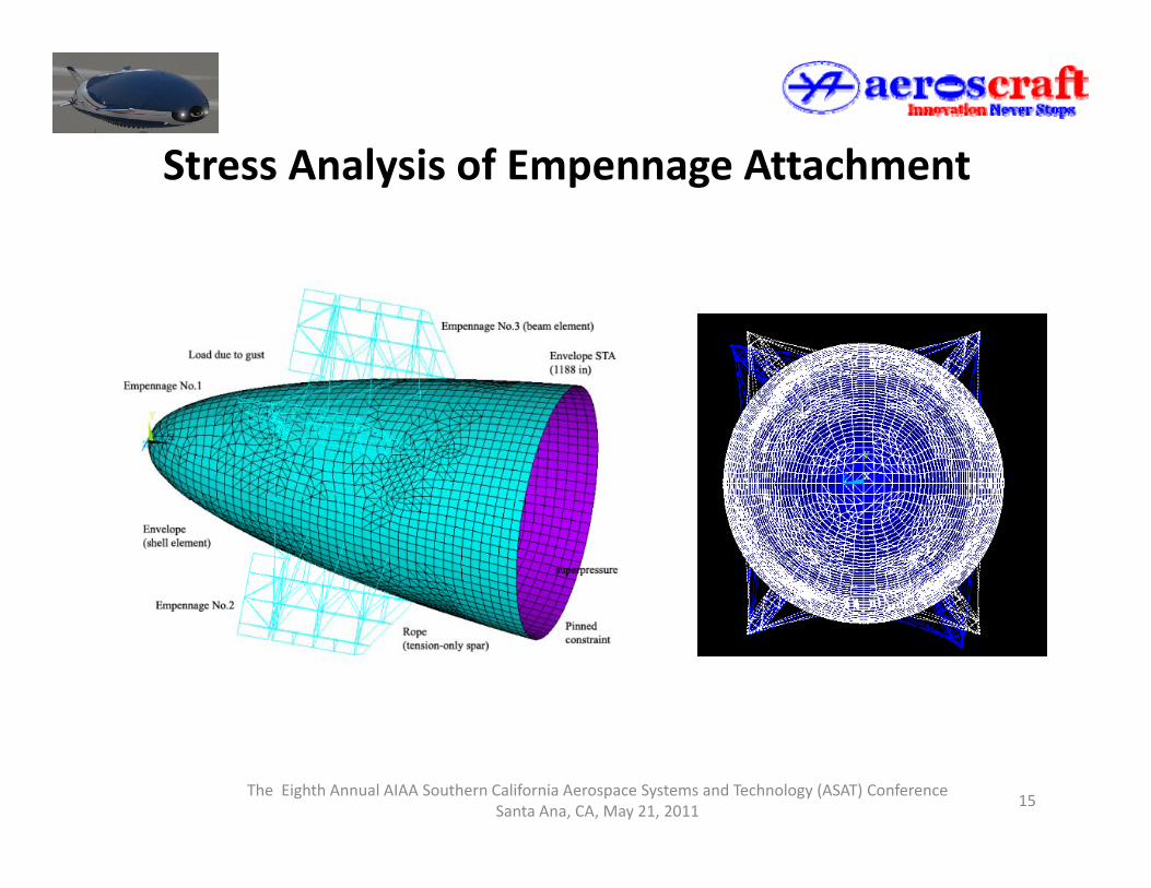
Stress Analysis of Empennage AttachmentStress Analysis of Empennage Attachment
15The Eighth Annual AIAA Southern California Aerospace Systems and Technology (ASAT) Conference
Santa Ana, CA, May 21, 2011
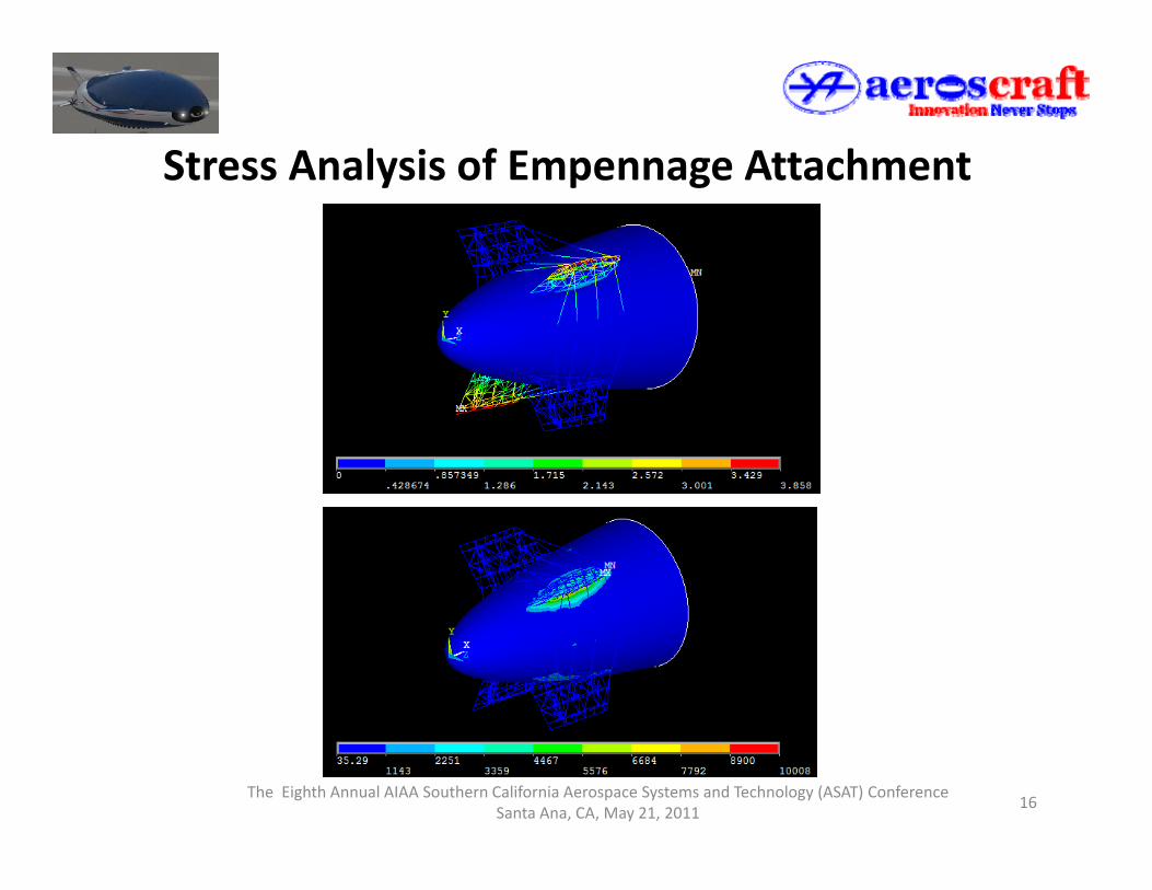
Stress Analysis of Empennage AttachmentStress Analysis of Empennage Attachment
16The Eighth Annual AIAA Southern California Aerospace Systems and Technology (ASAT) Conference
Santa Ana, CA, May 21, 2011

Cable truss StructuresCable_truss Structures
Restraints: fixed Nodes1, 4, and 5Applied loads:Fx =1000 lbs at Nodes 9, 10, 11, 12
bl i lbCable pretension: 100 lbs
Cable tension in the deformed configuration
Cable C1 C2 C3 C4 C5 C6 C7 C8 C9T i (lb ) 156 96 43 07 113 38 86 79 200 95 0 7 79 192 92 43 72Tension (lbs) 156.96 43.07 113.38 86.79 200.95 0 7.79 192.92 43.72
Cable C10 C11 C12 C13 C14 C15 C16 C17 C18Tension (lbs) 156.17 82.68 116.89 95.04 104.26 263.12 0 235.79 0
17The Eighth Annual AIAA Southern California Aerospace Systems and Technology (ASAT) Conference
Santa Ana, CA, May 21, 2011

Cable truss StructuresCable_truss Structures
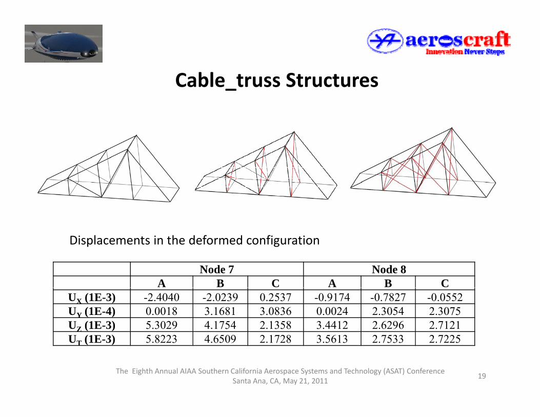
Restraints: fixed Nodes1-5, 9-13Restraints: fixed Nodes1 5, 9 13Applied loads: Fz =400 lbs at Nodes 7, 8, 15, 16Cable pretension: 100lbs
Th D i C fi iThree Design Configurations:Design A: no cables are usedDesign B: six cables are includedDesign C: 14 cables (Each of four truss members is replaced by two cables)
The Eighth Annual AIAA Southern California Aerospace Systems and Technology (ASAT) ConferenceSanta Ana, CA, May 21, 2011
18
Design C: 14 cables (Each of four truss members is replaced by two cables)
Cable truss StructuresCable_truss Structures
Node 7 Node 8A B C A B C
Displacements in the deformed configuration
UX (1E-3) -2.4040 -2.0239 0.2537 -0.9174 -0.7827 -0.0552UY (1E-4) 0.0018 3.1681 3.0836 0.0024 2.3054 2.3075UZ (1E-3) 5.3029 4.1754 2.1358 3.4412 2.6296 2.7121U (1E-3) 5 8223 4 6509 2 1728 3 5613 2 7533 2 7225
The Eighth Annual AIAA Southern California Aerospace Systems and Technology (ASAT) ConferenceSanta Ana, CA, May 21, 2011
19
UT (1E-3) 5.8223 4.6509 2.1728 3.5613 2.7533 2.7225

Cable truss StructuresCable_truss Structures
Design Node 5 Node 6Ux Uy Uz Ut Ux Uy Uz Ut
A (all) 2 8882 0 6030 4 3362 5 2448 2 5297 0 36406 2 5316 3 5973
Displacements in the deformed configuration
A (all) -2.8882 0.6030 -4.3362 5.2448 -2.5297 0.36406 -2.5316 3.5973B(1/2) -1.0161 0.4342 -1.5344 1.8909 -0.5751 0.1376 -0.5817 0.8295
C(1/2/3/4) -2.8342 0.1595 -4.2621 5.1209 -2.5728 -0.01747 -2.5788 3.6428D(5/6) -0.3899 -0.05827 -0.5891 0.7088 -0.3134 -0.1107 -0.3155 0.4583E(9/10) -0.4838 0.09942 -0.7368 0.8870 -0.2231 -0.07710 -0.2292 0.3290
The Eighth Annual AIAA Southern California Aerospace Systems and Technology (ASAT) ConferenceSanta Ana, CA, May 21, 2011
20
F(7/8/9/10) -0.4878 0.06495 -0.7428 0.8910 -0.2172 -0.1181 -0.2233 0.3331

Summary
Rigid body motion analysis has been utilized to study a variety of flightmaneuver conditions of airships.
Summary
maneuver conditions of airships.
Static bending moment and aerodynamic bending moment are calculated.Aerodynamic bending moment increases with the increase of airship lengthand increases with the decrease of equivalent max diameter for the samevolume and prismatic coefficients. Airship envelope stress is expressed as afunction of bending moment and internal pressure.
Finite element model of empennage attachment of airships is presented.
C bl t i h i ifi tl i t t ith t i d blCable tension changes significantly in contrast with pretension and cablescould completely lose tension. Optimal cable pretension and configurationare helpful for the minimization of structural deformation.
21The Eighth Annual AIAA Southern California Aerospace Systems and Technology (ASAT) Conference
Santa Ana, CA, May 21, 2011

Thank You!
Questions?
Suggestions?
22The Eighth Annual AIAA Southern California Aerospace Systems and Technology (ASAT) Conference
Santa Ana, CA, May 21, 2011