AirSep Corporation PSA Oxygen Generator Model AS-Q - AS-Z › downloads › AirSep ›...
155
AirSep ® Corporation PSA Oxygen Generator Model AS-Q - AS-Z Instruction Manual MN173-1 Rev. B 03/12 AirSep ® Corporation 260 Creekside Drive Buffalo, NY 14228-2075 USA Phone: 1-800-320-0303 Fax: (716) 691-1255
Transcript of AirSep Corporation PSA Oxygen Generator Model AS-Q - AS-Z › downloads › AirSep ›...

AirSep® Corporation PSA Oxygen Generator Model AS-Q - AS-Z
Instruction Manual
MN173-1 Rev. B 03/12
AirSep® Corporation 260 Creekside Drive Buffalo, NY 14228-2075 USA Phone: 1-800-320-0303 Fax: (716) 691-1255


Ownership Data
Please take a moment to note below important information about your AirSep® Corporation PSA Oxygen Generator. Retain this instruction manual, along with your invoice, to serve as a permanent record of your purchase.
PSA Oxygen Generator
Model Number:
Serial Number:
Invoice Date:
Start-up Date:
AirSep Representative
Company:
Contact:
Address:
City/Town: State: Zip:
Country: Fax:
Phone: Telex:
Before you attempt to install, operate, or repair the oxygen generator, read and thoroughly understand this instruction manual. Improper operation can result in severe bodily injury, damage to the oxygen generator, or poor performance.

AirSep® Corporation
AS-Q — AS-Z Series Instruction Manual i
Table of Contents
1.0 Introduction ..................................................................................... 1-1
1.1 General ............................................................................................. 1-1
1.2 Warnings, Cautions, and Notes ........................................................ 1-1
1.3 References to Controls and Indicators ............................................. 1-1
2.0 Safety ................................................................................................ 2-1
2.1 General ............................................................................................. 2-1
2.2 Potential Hazards ............................................................................. 2-1
2.3 Safety Publications ........................................................................... 2-3
3.0 System Description ......................................................................... 3-1
3.1 General ............................................................................................. 3-1
4.0 Components Description ................................................................ 4-1
4.1 General ............................................................................................. 4-1
4.2 Adsorber Vessels .............................................................................. 4-1
4.3 Filter Assembly ................................................................................. 4-2
4.4 Pressure Switch Sub-assembly ........................................................ 4-2
4.5 Product Output Sub-assembly .......................................................... 4-3
4.6 Feed and Waste Manifold Assembly ................................................ 4-4
4.7 Equalization and Purge Manifold Assembly ..................................... 4-4
4.8 Control Panel: Internal Components ................................................. 4-5
4.9 Control Panel: External Components ............................................... 4-6
5.0 Installation ....................................................................................... 5-1
5.1 Unpacking ......................................................................................... 5-1
5.2 Pre-Installation Guidelines ................................................................ 5-3
5.3 Installation Instructions ..................................................................... 5-3

AirSep® Corporation
ii AS-Q — AS-Z Series Instruction Manual
6.0 System Operation ............................................................................ 6-1
6.1 General ............................................................................................. 6-1
6.2 Initial Start-Up ................................................................................... 6-1
6.3 Operation .......................................................................................... 6-4
6.4 Shutdown .......................................................................................... 6-4
6.5 Normal Start-Up ................................................................................ 6-5
6.6 Extended Shutdown .......................................................................... 6-5
6.7 Start-Up After an Extended Shutdown .............................................. 6-6
7.0 Maintenance ..................................................................................... 7-1
7.1 General ............................................................................................. 7-1
7.2 Daily Maintenance ............................................................................ 7-1
7.3 Semi-Annual Maintenance ................................................................ 7-2
7.4 Annual Maintenance ......................................................................... 7-4
8.0 Troubleshooting .............................................................................. 8-1
8.1 General ............................................................................................. 8-1
8.2 Troubleshooting Chart ...................................................................... 8-2
A Appendix: Technical Data .............................................................. A-1
B Appendix: Warranty/Returns ....................................................... B-1
C Appendix: Parts List ...................................................................... C-1
D Appendix: Component Literature ................................................ D-1

AirSep® Corporation
AS-Q — AS-Z Series Instruction Manual iii
List of Illustrations
Figure 4.1: General Layout of the Oxygen Generator ............................ 4-1
Figure 4.2: Typical Filter Assembly ......................................................... 4-2
Figure 4.3: Typical Product Output Sub-assembly ................................... 4-3
Figure 4.4: Typical Feed & Waste Manifold Assembly .............................. 4-4
Figure 4.5: Typical Main System Control Screen .................................... 4-6
Figure 4.6: HMI Navigation Layout ........................................................... 4-7
Figure 4.7: Typical Oxygen Generator Screen ......................................... 4-8
Figure 4.8: Typical Parameters and Output Screen ................................ 4-9
Figure 4.9: Typical Bed Pressure Graphs Screen ................................... 4-9
Figure 4.10: Typical Bed Pressure Calibration Screen ......................... 4-10
Figure 4.11: Feed Air Pressure Transducer Assembly ......................... 4-11
Figure 5.1: Typical Oxygen Outlet Manifold on Oxygen Receiver .......... 5-5
Figure A.1: General Arrangement Drawing – AS-Q ................................ A-9
Figure A.2: General Arrangement Drawing – AS-R .............................. A-10
Figure A.3: General Arrangement Drawing – AS-W ............................. A-11
Figure A.4: General Arrangement Drawing – AS-Z .............................. A-12
Figure A.5: Process & Instrumentation Drawing – AS-Q, AS-R, AS-W and AS-Z ................................................................................. A-13
Figure A.6: Electrical Schematic - I ....................................................... A-14
Figure A.7: Electrical Schematic - II ...................................................... A-15
Figure A.8: Electrical Schematic - III ..................................................... A-16
Figure A.9: Electrical Schematic - IV ..................................................... A-17


AirSep® Corporation
AS-Q - AS-Z Series Instruction Manual 1-1
1.0 Introduction
1.1 General
This instruction manual provides descriptions of the AirSep Corporation PSA Oxygen Generator Models AS-Q, AS-R, AS-W and AS-Z, as well as instructions for their installation, operation, and maintenance. The Appendix of this instruction manual also includes pertinent drawings and component literature.
To ensure safe operation and proper maintenance of the oxygen generator, AirSep Corporation recommends that you keep this instruction manual readily available for reference.
1.2 Warnings, Cautions, and Notes
As you read this instruction manual, pay special attention to the WARNING, CAUTION, and NOTE messages. They identify safety guidelines or other important information as follows:
Provides information that can prevent severe bodily injury or death.
Cautions against the risk of electric shock.
Provides information important enough to emphasize or repeat.
1.3 References to Controls and Indicators
This instruction manual uses uppercase characters (e.g., ON/OFF) to refer to the controls and the indicators on the touch screen of the oxygen generator. Numbers inside parentheses (e.g., V-2) identify manually operated flow
AirSep® Corporation
1-2 AS-Q - AS-Z Series Instruction Manual
controls (e.g., manual valves). Refer to Chapter 4 for description of the oxygen generator components for each model.

AirSep® Corporation
AS-Q — AS-Z Series Instruction Manual 2-1
2.0 Safety
2.1 General
Oxygen, the most abundant of the elements, makes up approximately 50 percent of the earth’s crust. In its free state, oxygen forms approximately one-fifth of our air by volume. Although classified as a non-flammable gas, oxygen supports combustion. As an active element, it combines directly or indirectly with all elements except the rare gases. Oxygen is an invisible gas that is colorless, odorless, and tasteless.
To ensure your safety, thoroughly read and familiarize yourself with the entire section of this instruction manual. In addition, AirSep Corporation strongly recommends that you review this section periodically.
2.2 Potential Hazards
Oxygen vigorously accelerates the burning of combustible materials. In an oxygen-enriched atmosphere, many materials that do not burn in normal air require only a slight spark or moderate heat to set them aflame.
To reduce the risk of fire or explosion, keep gasoline, kerosene, oil, grease, cotton fibers, wood, paint, and other combustible material away from all parts of the oxygen generator.
Do not allow smoking, open flame, or usage of electronic devices that may generate sparks near the oxygen generator.
Post “NO SMOKING OR OPEN FLAMES” signs conspicuously near the location of the oxygen generator.
Take extreme care to keep all oxygen piping and vessels clean. To avoid fire or explosion, oxygen clean all surfaces that can come in contact with the product oxygen. Check all oxygen fittings for leaks with an oxygen-compatible, leak-detecting solution.

AirSep® Corporation
2-2 AS-Q — AS-Z Series Instruction Manual
To prevent fire or electrical shock, locate the oxygen generator indoors, away from rain or any other type of moisture.
Before you attempt to install, operate, or repair the oxygen generator, read and thoroughly understand this instruction manual and the component manuals located in Appendix D of this instruction manual. Improper installation, operation, or repairs can result in severe bodily injury, damage to the oxygen generator, or poor performance.
The interior of the oxygen generator control cabinet contains electrical parts that can produce an electrical shock hazard if not handled properly. To prevent electrical shock, read and thoroughly understand Section 8 — Troubleshooting in this instruction manual before you service the oxygen generator.
AirSep oxygen generators are sold for use in industrial applications only. Contact AirSep Corporation or an authorized AirSep representative before you use this unit for any medical application.
Disconnect power before servicing oxygen generator.
Do not disconnect protective earth.

AirSep® Corporation
AS-Q — AS-Z Series Instruction Manual 2-3
2.3 Safety Publications
The safety section of this instruction manual is not a complete summary of required safety precautions. Few of the publications for additional information on the safe handling of oxygen are listed below:
"Installation of Bulk Oxygen Systems at Consumer Sites;" NFPA No. 50; National Fire Protection Association; 1 Batterymarch Park; P. O. Box 9101; Quincy, Massachusetts 02269-9101 USA.
"Oxygen;" Pamphlet G-4; Compressed Gas Association; 1725 Jefferson Davis Highway; Arlington, Virginia 22202-4102 USA.
"Cleaning Equipment For Oxygen Service," Pamphlet G-4.1; Compressed Gas Association; 1725 Jefferson Davis Highway; Arlington, Virginia 22202-4102 USA.


AirSep® Corporation
AS-Q — AS-Z Series Instruction Manual 3-1
3.0 System Description
3.1 General
Air Contains 21 % oxygen, 78% nitrogen, 0.9% argon, and 0.1% other gases. AirSep PSA Oxygen units separate this small percentage of oxygen from compressed air through a unique Pressure Swing Adsorption (PSA) process. The compressed air flows through a filter assembly before the air enters the adsorber vessels. A particulate filter removes condensed water, oil, dirt, scale, etc. from the feed air, and then a separate coalescing filter (mounted on most of the models) removes additional oil and water vapor.
The oxygen generator uses in its adsorber vessels an inert ceramic material called molecular sieve to separate compressed air into oxygen and other gases. The unique properties of molecular sieve allow it to attract, or adsorb, nitrogen physically from air under pressure. This allows oxygen to exit the adsorbers as a product gas. The process valves on the oxygen generator then direct the oxygen to the oxygen receiver for storage until needed by your application.
While one adsorber produces oxygen, the other depressurizes to exhaust the waste gases it adsorbed (collected) during the oxygen production cycle. The entire oxygen generating process is completely regenerative, which makes it both reliable and virtually maintenance-free. The molecular sieve does not normally require replacement.
This instruction manual serves as the guidelines for all the standard AS-Q through AS-Z series models.


AirSep® Corporation
AS-Q — AS-Z Series Instruction Manual 4-1
4.0 Components Description
4.1 General The chapter deals with the description of the various components of the AS-Q - AS-Z series oxygen generators. The components of the oxygen generator are grouped and are described in the following sub-sections of the chapter. Figure below displays the location of the major components of the oxygen generator.
Figure 4.1: General Layout of the Oxygen Generator
4.2 Adsorber Vessels The adsorbers, or beds, are vessels that contain the molecular sieve used to adsorb (attract) nitrogen from compressed air and allow oxygen to pass through as the product gas.
Filter Assembly
Adsorber Vessels
Equalization Manifold
Control Panel
Feed & Waste Manifold
Product o/p Manifold
Pressure Transducer for Bed A (PT2)
Pressure Transducer for Bed B (PT3)
Product Pressure Transducer (PT4)

AirSep® Corporation
4-2 AS-Q — AS-Z Series Instruction Manual
4.3 Filter Assembly
The filter assembly consists of two filters. The particulate filter, or pre-filter, removes particulates from the feed air before the air enters the coalescing filter and the coalescing filter removes condensed water, oil vapor, and other contaminants from the feed air before the air enters the adsorbers.
Figure 4.2: Typical Filter Assembly
Particulate Filter Drain (V-D1)
This automatic valve removes moisture from the particulate filter.
Coalescing Filter Drain (V-D2)
This automatic valve removes moisture from the coalescing filter.
Manual Feed #1 Valve (V-1)
This manual valve (if available) controls the flow of feed air from the air compressor to the filter assembly.
4.4 Pressure Switch Sub-assembly
The assembly is located before the inlet ball valve (V-2) of the feed and waste manifold (Section 4.6). It solves the purpose of monitoring the feed air pressure. The assembly also regulates the flow of air through all the automatic valves.
Manual Valve to Pressure Switch This manual valve controls the flow of air to the pressure switch on the oxygen generator. The valve should not be closed at any circumstance while the unit is running.
V-1
V-D1
V-D2

AirSep® Corporation
AS-Q — AS-Z Series Instruction Manual 4-3
4.5 Product Output Sub-assembly
The product output sub-assembly directs the oxygen flow to the oxygen receiver and the pressure transducer (PT4).
Figure 4.3: Typical Product Output Sub-assembly
Manual Product Valve (V-3)
This manual valve controls the flow of oxygen from the product manifold to the oxygen receiver.
Manual Valve to Pressure Transducer (PT4)This manual valve controls the flow of oxygen to the pressure transducer (PT4) on the oxygen generator. The valve should not be closed at any circumstance while the unit is running except for the purpose of calibration. In some AS models, the two manual valves for PT4 are replaced by a three way valve.
Connects to Equalization Manifold Outlet
PT4
V-3Manual Valve for PT4
Manual Valve for Calibration of PT4
Outlet for Oxygen Hose Connection

AirSep® Corporation
4-4 AS-Q — AS-Z Series Instruction Manual
4.6 Feed and Waste Manifold Assembly
The feed and waste manifold includes all the process valves: feed air through valves V-FA, V-FB, and waste gas from the valves V-WA, V-WB.
Figure 4.4: Typical Feed & Waste Manifold Assembly
Manual Feed #2 Valve (V-2)This manual valve controls the flow of feed air from the air compressor, through the filter assembly, to the feed and waste manifold.
Vent Silencers (not shown) The vent silencers muffle the sound of the waste gas as it exits the adsorbers.
Cycle Pressure Gauge The cycle pressure gauge indicates the pressure of the feed air before the air enters the adsorbers.
4.7 Equalization and Purge Manifold Assembly The manifold includes all the process valves (V-EA, V-EB and V-PU) that direct the flow of oxygen from the adsorbers.
V-2
Cycle Pressure Gauge
V-FA
V-WA V-WB
V-FB

AirSep® Corporation
AS-Q — AS-Z Series Instruction Manual 4-5
4.8 Control Panel: Internal Components
Programmable Logic Controller (PLC)
The oxygen generator uses a programmable logic controller to control and monitor all valves, interfaces and switches on the oxygen generator.
Transformer
The transformer provides the proper voltage for the electrical components of the oxygen generator.
Terminal Block (TB1)
The terminal block provides the connection point for electrical wiring that supplies electrical power to the oxygen generator.
EMI Filter (EMI1)
The EMI filter eliminates electrical line interference from the incoming power source.
Circuit Breakers
The circuit breakers protect the electrical components of the oxygen generator from any damaging electrical current if an overload occurs.

AirSep® Corporation
4-6 AS-Q — AS-Z Series Instruction Manual
4.9 Control Panel: External Components
Allen-Bradley Touch Screen
The touch screen on the oxygen generator control panel uses a series of screen pages to perform the following functions:
Provides a normal start-up system
Monitors and controls the operation of the process valves;
Monitors signals coming from pressure transducers.
Provides an alarm system to indicate malfunctions in the PSA Oxygen Generating System.
Provides a fail-safe shutdown in the event of loss in product purity.
The main Human/Machine Interface (HMI) consists of the Allen Bradley PanelView Plus 600 Touch screen. The PanelView Plus has a 5.5” screen, which is touch-sensitive.
In order to make the software simple to use, the various screens follow a consistent template design. Each screen consists of two components: the title bar and the information display.
Figure 4.5: Typical Main System Control Screen
The title bar serves two purposes. It identifies the screen that is currently being displayed. It also acts as the main navigational tool.
Maintenance
ScreenCleaning
Information Display
Title Bar


AirSep® Corporation
4-8 AS-Q — AS-Z Series Instruction Manual
on your right while facing the control panel) are shown in the center of the screen and the oxygen receiver vessel is shown on the right hand side of the screen. The receiver has a numeric pressure display. Additionally, the diagram shown will animate to indicate which valves are currently being actuated. The ‘AUTO/MAN’ icon selects the operating mode for the oxygen generator. In the AUTO position, the oxygen generator cycles on and off to meet oxygen demand.
When the pressure in the product output manifold/oxygen receiver reaches auto standby upper setpoint pressure, the oxygen generator stops oxygen production after a timed delay and enters standby mode. This time delay is approx 3-5 min. The time delay is to prevent short cycling and maintain purity. This time delay to the generator standby functions only in the Auto mode.
When the pressure in the product output manifold/oxygen receiver decreases to approximately the auto standby lower setpoint pressure, the oxygenproduction begins.
In the MANUAL position, the oxygen generator cycles continuously. The symbol ‘A’ at the right side of the ‘AUTO/MAN’ switch appears only when theoxygen generator is in AUTO mode.
Figure 4.7: Typical Oxygen Generator Screen
The ‘Parameters and Output’ Screen is the main location to observe the several parameters of the oxygen generator. The bed pressures, oxygen receiver pressure, oxygen purity and the number of working hours, are all displayed here via Message Displays. The ‘Yearmeter’ counts 8000 hours as

AirSep® Corporation
AS-Q — AS-Z Series Instruction Manual 4-9
one year so that after 8000 hours, ‘Hourmeter’ resets to zero and the ‘Yearmeter’ counter increases by unity.
Figure 4.8: Typical Parameters and Output Screen
The ‘Bed Pressure Graphs’ icon takes to the Bed Pressure Graphs Screen as shown.
Figure 4.9: Typical Bed Pressure Graphs Screen

AirSep® Corporation
4-10 AS-Q — AS-Z Series Instruction Manual
The ‘Output Parameter Graphs’ icon takes to the screen that displays the graphs between oxygen pressure Vs time and the oxygen purity Vs time. The ‘Next Pen’ icon changes the scale of the ordinate to suit the respective displayed pressure.
The ‘Calibrate Pressure Transducers’ icon takes to a screen dedicated to the pressure transducers calibration and settings as shown below.
Figure 4.10: Typical Bed Pressure Calibration Screen
The pressure transducers for the beds and the product oxygen pressure are factory calibrated and should not require any calibration for a long period. However, if the need arises, follow the procedure below for calibration.
1. To calibrate pressure transducer, press the ‘BYPASS TRANSMITTERS’ icon on the screen to bypass the pressure transducer signal to the PLC. The text of the icon will change to ‘TRANSMITTERS BYPASSED’ as shown in Figure 4.10.
2. The three-way valve (V-A) (Figure 4.9) handle shows the direction of flow path. In Figure 4.11, direction of flow path is from oxygen generator to pressure transducer. Close this manual three-way valve (V-A), so that the flow path is from the atmosphere to the pressure transducer.
3. Take out the plug, if any, from the port A (Figure 4.11) and attach a manual air pump having an accurate pressure gauge.

AirSep® Corporation
AS-Q — AS-Z Series Instruction Manual 4-11
4. Press the ‘Calibrate 0 psig’ icon when the gauge on the manual air pump reads 0 psig.
5. Manually pump the air so that the pressure reading on the gauge is 100 psig.
6. At this point, press the ‘Calibrate 100 psig’ icon on the calibration screen to finish the calibration procedure.
Figure 4.11: Feed Air Pressure Transducer Assembly
7. Disconnect the manual air pump from the port A and put the plug, if any, back to the port A.
8. Open the manual three-way valve (V-A), so that the flow path is from the oxygen generator to the pressure transducer as shown in Figure 4.11.
9. Press the ‘TRANSMITTERS BYPASSED’ icon to reactivate the signals of pressure transducers.
Press the ‘NEXT’ icon to navigate the calibration screen for the oxygen receiver pressure transducer.
If ‘BYPASS TRANSMITTERS’ icon is pressed, it will bypass the transmitter for 10 minutes and then it resets itself. However, it also acts as a toggle icon and if pressed again before the expiry of 10 minute time period, the icon resets.
OxygenGenerator
ManifoldConnection
V-A
Direction of flow path shown from oxygen generator to pressure transducer
Port A (shown open to atmosphere)

AirSep® Corporation
AS-Q — AS-Z Series Instruction Manual 5-1
5.0 Installation
5.1 Unpacking
AirSep Corporation ships the oxygen generator on a wooden skid along with the filter assembly. In the AS-Z series models, vent silencer assembly is also shipped apart from the oxygen generator and filter assembly. The oxygenreceiver, if supplied, is also shipped on a separate skid.
Follow these unpacking guidelines carefully to protect yourself against loss from any damage that occurred during shipment.
1) Thoroughly inspect the exterior of the oxygen generator, filter assembly, vent silencer assembly and oxygen receiver, if supplied, for any damage that occurred during shipment. Pay special attention to the control cabinet on the oxygen generator. Open the control cabinet door, and inspect the interior for damage. If you observe any damage, note it on the freight bill or the express receipt before you sign it.
Failure to note any exterior damage on the freight bill or the express receipt at the time of delivery can result in the refusal of a damage claim by the carrier.
2) Carefully cut and remove any banding straps from the oxygen generator, filter assembly, vent silencer assembly and oxygen receiver, if supplied.
Remove all packing material very carefully. Retain the packing material for use if any additional shipping is required.
Use extreme caution when you lift the oxygen generatorfrom the pallet. Lift only by the two lifting lugs at the top of the unit.

AirSep® Corporation
5-2 AS-Q — AS-Z Series Instruction Manual
3) Carefully stand the oxygen generator on its legs.
Use extreme care when you handle any part of the oxygen generator to prevent damage.
4) Carefully stand the oxygen receiver, if supplied, on its base.
5) Although the oxygen generator, the filter assembly, the vent silencer assembly and the oxygen receiver are carefully inspected, tested, and packed, they can be damaged during shipment due to improper handling. If you find any concealed damage (loss or damage not found until you unpack the oxygen generator, filter assembly, vent silencer assembly and oxygen receiver), immediately call the delivery carrier and file a concealed-damage claim. Retain ALL container materials and interior packing for the carrier's inspection.
You must make a concealed damage claim within 24 hours of delivery. Only the consignee can file this claim.

AirSep® Corporation
AS-Q — AS-Z Series Instruction Manual 5-3
5.2 Pre-Installation Guidelines
Before you install the oxygen generator, filter assembly, vent silencer assembly and oxygen receiver, if supplied, refer to the Specifications section of this instruction manual to determine applicable floor space, feed air, and power requirements for your particular model.
The oxygen generator may use feed air at specifications outside those shown in this instruction manual; however, use of such feed air may require modification of the oxygen generator at the AirSep Corporation factory to ensure the product oxygen meets the specifications. Consult your sales representative to determine whether your oxygen generator requires modifications for your application.
Locate the oxygen generator in an area where the ambient air temperature remains between 4 C (40 F) and 40 C(104 F) to prevent damage not covered under the AirSep Corporation Product Warranty.
AirSep oxygen generators are sold for indoor use only.Provide adequate ventilation at the location where you install the oxygen generator to ensure that the ambient air circulates readily. If the oxygen generator malfunctions or is not operated properly, inadequate ventilation may allow the ambient air to become either oxygen deficient or oxygen enriched.
5.3 Installation Instructions
The section illustrates the standard installation arrangement.
Do not connect the filter assembly outlet directly to the feed air inlet on the oxygen generator. The feed air piping on the oxygen generator does not provide adequate support for the weight of the filter assembly.

AirSep® Corporation
5-4 AS-Q — AS-Z Series Instruction Manual
Feed air at a temperature above 50°C (122°F) can cause damage to the oxygen generator not covered under the AirSep Corporation Product Warranty.
AirSep Corporation recommends installation of a shut-off valve on your air receiver. The shut-off valve enables safe depressurization of the feed air piping and air receiver to perform maintenance or repairs.
1) On the AS-Z models, connect the vent silencer assembly to the oxygen generator (Refer to Appendix A of this instruction manual for general layout drawings of the AS-Z models which show the vent silencer):
a) Install the bracket provided to the rear of the oxygen generator. b) Connect the oxygen generator exhaust outlet to the flanged pipe
provided with the vent silencer assembly.c) Remove the flange covers, if any, from the flange at the base of the
vent silencer assembly and the flange at the base of the rear of the oxygen generator.
d) Connect the flanges at the base of the vent silencer assembly and rear of the oxygen generator. Take care not to damage the gasket between the flanges during installation.
e) Connect the mufflers provided for the silencer assembly.
2) Remove the flange cover from the filter assembly inlet and outlet flange.
3) Connect the filter assembly to the oxygen generator after providing support to the filter assembly.
4) Connect the filter assembly inlet flange to the piping from your source of feed air. Provide clean piping with enough length to provide support for the weight of the filter assembly. Take care not to damage the gasket between the flanges during installation.
5) Install your oxygen receiver supplied by AirSep Corporation. If AirSep Corporation supplied the oxygen receiver, install a relief valve and oxygen outlet manifold to complete its assembly. AirSep Corporation recommends, if not supplied, the oxygen outlet manifold contain a manual ball valve, a vent valve with muffler, a pressure gauge, and a pressure regulator. If your application includes an oxygen analyzer or monitor, install an outlet with a manual ball valve on the oxygen outlet manifold to provide an oxygen sample.

AirSep® Corporation
AS-Q — AS-Z Series Instruction Manual 5-5
Take extreme care to keep all oxygen piping, hoses, and vessels clean. To avoid fire or explosion, oxygen clean all surfaces that can come in contact with the product oxygen.
Figure 5.1: Typical Oxygen Outlet Manifold on Oxygen Receiver
6) Install the oxygen regulator assembly on the oxygen receiver.
7) Connect the respective electrical wires to the automatic drain valves of the filter assembly. Refer to the Appendix A of the instruction manual for the electrical schematics pertinent to the oxygen generator model.
8) Remove the plug from the oxygen outlet on the oxygen generator. Take care to prevent contamination from dust, oil, grease, etc. of the oxygen outlet and oxygen hose or piping.
9) Connect the oxygen outlet to the oxygen hose or piping to the oxygen receiver. Use Teflon™ tape to seal threaded connections.
10) Connect electrical wiring to the appropriate power supply.
Oxygen Sample Port and Manual
Valve
Manual Outlet Ball Valve
Muffler
Manual Vent Valve
Pressure Gauge
Pressure Regulator
Tee Connection from Oxygen
Receiver to Oxygen Outlet
Manifold
Oxygen Outlet

AirSep® Corporation
5-6 AS-Q — AS-Z Series Instruction Manual
AirSep Corporation recommends the connection of the oxygen generator’s terminal block to a circuit that cannot be accidentally turned off. An accidental shutdown causes the oxygen generator to stop cycling randomly and results in initially lower purity oxygen during the subsequent start-up. If electrical power is off while your application uses oxygen, the oxygen receiver depressurizes.
Provide proper voltage to the oxygen generator. Improper voltage causes damage not covered under the AirSep Corporation Product Warranty.

AirSep® Corporation
AS-Q — AS-Z Series Instruction Manual 6-1
6.0 System Operation
6.1 General
This section of the instruction manual provides the procedures for start-up and shutdown of the oxygen generator. Review the component literature provided in the Appendix D of this instruction manual before you attempt to start the oxygen generator. Also read and thoroughly understand any literature or instruction manuals for components not provided by the AirSep Corporation.
Oxygen vigorously accelerates the burning of combustible materials. In an oxygen-enriched atmosphere, many materials that do not burn in normal air require only a slight spark or moderate heat to set them aflame.
Do not allow smoking, open flame, or electronic devices that may generate sparks (e.g., cellular telephones) near the oxygen generator.
Post “NO SMOKING OR OPEN FLAMES” signs conspicuously near the location of the oxygen generator.
6.2 Initial Start-Up To start the oxygen generator for the first time, or after an extended or unexpected shutdown, follow the steps below:
1) Supply electrical power to the oxygen generator.
2) Refer to Figure 4.1 for the location of the pressure transducers (PT2, PT3 and PT4). Refer to the following chart to set the position of the manual valves on the oxygen generator prior to the initial start-up. Make sure each valve is fully open or fully closed, as indicated in the chart.
Valve Description Valve No. Initial
Start-UpPosition
NormalOperatingPosition
MANUAL FEED #1 valve (if applicable) V-1 Open* Open*MANUAL FEED #2 valve V-2 Closed OpenMANUAL PRODUCT valve V-3 Open OpenManual valve for Pressure Switch --- Open OpenManual valve for PT2** --- Open OpenManual valve for calibration of PT2** --- Closed ClosedManual valve for PT3** --- Open OpenManual valve for calibration of PT3** --- Closed ClosedManual valve for PT4** --- Open OpenManual valve for calibration of PT4** --- Closed Closed

AirSep® Corporation
6-2 AS-Q — AS-Z Series Instruction Manual
Manual inlet valve of receiver --- Open OpenManual valve to gauge on receiver --- Open OpenManual sample valve --- Closed OpenManual vent valve --- Closed ClosedManual outlet valve of receiver --- Closed OpenManual outlet valve to application --- Closed Open* Also open all manual valves prior to MANUAL FEED #1 valve ** If a three way valve is installed for PT2, PT3 and PT4, ensure that the flow path is from oxygen generator to the pressure transmitter and not from atmosphere to the pressure transmitter.
Table 6.1 – Manual Valve Position Chart
3) Supply the compressed air.
4) Make sure the feed air supplied is within the feed air pressure range specified in this instruction manual.
5) Press the ‘AUTO/MAN’ icon on the Oxygen Generator Control Screen so that the oxygen generator is in MANUAL mode.
6) Press the ‘ALARM RESET’ icon on the Oxygen Generator Control Screen. The generator will only start if there is no shutdown condition existing. However, during start-up, a low purity alarm may exist. If a shutdown condition exists, pressing the ‘ALARM RESET’ will not reset the system.
Please note that during initial start-up or start-up after a long period, the oxygen purity can be lower than the low purity alarm and/or shutdown setpoint and a ‘low purity’ alarm may exist. However, the oxygen generator ignores the oxygen purity shutdown setpoint for the first 60 minutes after start-up. If the oxygen purity after 60 minutes of operation is still below the low purity shutdown setpoint, the oxygen generator shuts down.
The FEED PRESSURE must be above the feed air low pressure shutdown level specified in this instruction manual for the oxygen generator to run.
7) Make sure the POWER lights on the automatic drain valves at the base of the filter bowls illuminate. Press the manual override buttons on the PARTICULATE FILTER DRAIN valve and the COALESCING FILTER DRAIN valve, and make sure air discharges from the drain outlets.
Make sure the exhaust contains no liquid. If liquid discharges, press the manual override buttons on the drain valves until the exhaust no longer contains liquid.
AirSep® Corporation
AS-Q — AS-Z Series Instruction Manual 6-3
The automatic drains on the oxygen generator exhaust periodically during operation to remove condensate from the filter bowls.
8) Adjust the automatic drain timer so that the exhaust contains no liquid without overdrawing the feed air. The typical timing for the drain valve operation is 5 sec every 10 min.
9) Press the ‘START’ icon on the Oxygen Generator Control Screen. You may press the ‘Silence Horn’ icon on the main screen to silence the alarm due to low oxygen purity. The ‘Silence Horn’ icon bypasses the horn for 10 minutes.
10) Open the MANUAL FEED #2 valve (V-2) slightly. The valve should be open no more than 20-25%. Allow the unit to run this way until the bed pressures reach a maximum of 55-60 psig each cycle. This will take approximately 5 minutes. Once this pressure is reached, open the valve so that it is no more than 50% open. Allow the unit to run this way until the bed pressures reach a maximum of 60-65 psig each cycle. This will take approximately an additional 5 minutes. Lastly, open the valve so that it is no more than 75% open. Allow the unit to run this way until the bed pressures reach a maximum of 70-75 psig each cycle. This will take approximately an additional 5 minutes.
When initially starting the unit, the adsorber vessels and oxygen receiver will be completely empty. If the feed valve is fully open when the unit begins to run, all of the air from the feed compressor, feed air tank, and feed piping will rush into the empty generator. This will cause the pressure to drop below the low instrument air shutdown setpoint. By slowly throttling the feed valve, it allows the empty generator to be gradually filled to the point at which the feed valve can be fully opened to its normal operating condition.
11) To purge oxygen at less than design purity from the oxygen receiver, while the oxygen generator is running, open the manual vent valve on the oxygen receiver to vent gas. (This is the manual valve that vents low purity oxygen to the atmosphere to increase oxygen purity in the oxygen receiver to the level required for your application. Ensure that vent is sized such that the oxygen generator is never overdrawn.)
During initial start-up, while the feed air oxygen generator piping and hoses, oxygen lines, and oxygen receiver pressurize, apply soapy water to all feed air piping and connections, oxygen piping or hoses and connections, and oxygen receiver connections to check for leaks. Repair or replace the leaking item(s).

AirSep® Corporation
6-4 AS-Q — AS-Z Series Instruction Manual
12) Open the product sample valve to the oxygen analyzer assembly (if used) to monitor the purity of the oxygen. If an oxygen analyzer board is provided, ensure that the pressure regulator to the oxygen analyzer board is set at 5 psig.
13) When the oxygen analyzer indicates the purity of the oxygen in the oxygen receiver that exceeds the minimum purity specified in this instruction manual, close the manual vent valve.
14) Fully open the manual outlet valves that control the flow of oxygen from the oxygen receiver to your application, and set the pressure regulator on the oxygen receiver outlet manifold to the pressure required for your application.
15) Press the ‘AUTO/MAN’ icon on the Oxygen Generator Screen so that the oxygen generator comes in AUTO mode.
6.3 Operation
AUTO Mode When the ‘AUTO/MAN’ icon on the oxygen generator touch screen is in the AUTO mode, the oxygen generator cycles on and off automatically based on oxygen demand. When the product oxygen pressure increases to the approximate maximum pressure specified in this instruction manual, oxygen production stops after one cycle and the generator enters standby mode. When your application uses enough oxygen to decrease the oxygen receiver pressure to approximately the minimum pressure specified in this instruction manual, the oxygen generator resumes oxygen production. The AUTO mode enables the most energy-efficient operation of the oxygen generator. Use the AUTO mode during normal operation and to shut down the oxygen generator.
MANUAL Mode With the ‘AUTO/MAN’ icon on the oxygen generator touch screen in the MANUAL mode, the oxygen generator cycles continuously, regardless of the pressure in the oxygen receiver. Use the MANUAL mode during initial start-up or start-up after an extended shutdown of the oxygen generator and, depending on the oxygen flow, pressure, and purity requirements of your application, as directed by your AirSep Corporation representative.
6.4 Shutdown
1) Stop the flow of oxygen from the oxygen receiver to your application.
2) Make sure the ‘AUTO/MAN’ Icon on the Oxygen Generator Screen’ is in theAUTO mode. When the product oxygen pressure is higher than the maximum pressure set point, the oxygen generator stops cycling after a timed delay and enters the standby mode.
3) Press the ‘STOP’ icon on the Main System Control Screen.
4) If your oxygen receiver includes a manual sample gas valve to enable oxygen to flow to an oxygen analyzer, close it fully.

AirSep® Corporation
AS-Q — AS-Z Series Instruction Manual 6-5
5) Fully close the MANUAL PRODUCT valve (V-3).
6) Stop the supply of feed air.
6.5 Normal Start-Up
To perform a normal start-up, the oxygen generator first requires a shutdown as described in Section 6.4 — Shutdown. If the oxygen generator shuts down due to a power loss or inadequate feed air pressure, follow the procedure in Section 6.2 — Initial Start-Up to restart the oxygen generator.
1) Start the supply of compressed air.
2) Make sure the MANUAL FEED #1 (V-1) and #2 (V-2) valves are fully open.
3) Make sure the INSTRUMENT AIR valve is fully open.
4) Make sure the ‘AUTO/MAN’ icon on the oxygen generator control panel is in the AUTO mode.
5) When the feed air pressure exceeds the minimum feed air pressure specified in this instruction manual, press the ‘START’ icon on the Main System Control Screen.
6) Fully open the MANUAL PRODUCT valve (V-3) and the product sample valve.
The oxygen generator will not produce oxygen during a normal start-up until the product oxygen pressure is less than the minimum pressure specified in this instruction manual.
7) Start the flow of oxygen from the oxygen receiver to your application.
6.6 Extended Shutdown
To shut down the oxygen generator for 24 hours or longer, complete all the steps in Section 6.4 — Shutdown. In addition, perform the following steps:
1) Stop the supply of feed air.
2) Fully close the MANUAL FEED #1 (V-1) and MANUAL FEED #2 (V-2) valves.
3) Fully close the INSTRUMENT AIR valve.

AirSep® Corporation
6-6 AS-Q — AS-Z Series Instruction Manual
In addition, fully close any manual valves on the oxygen receiver. Close all manual valves to isolate the oxygen in the oxygen generator and oxygen receiver to prevent loss of oxygen pressure and enable a normal start-up.
6.7 Start-Up After an Extended Shutdown
After an extended shutdown or an unexpected shutdown, such as a loss of electrical power, you must purge the oxygen receiver of any low purity oxygen before the oxygen generator can supply oxygen within purity specifications. To purge the oxygen receiver, follow all the steps in Section 6.2 — Initial Start-Up.
AirSep® Corporation
AS-Q — AS-Z Series Instruction Manual 7-1
7.0 Maintenance
7.1 General
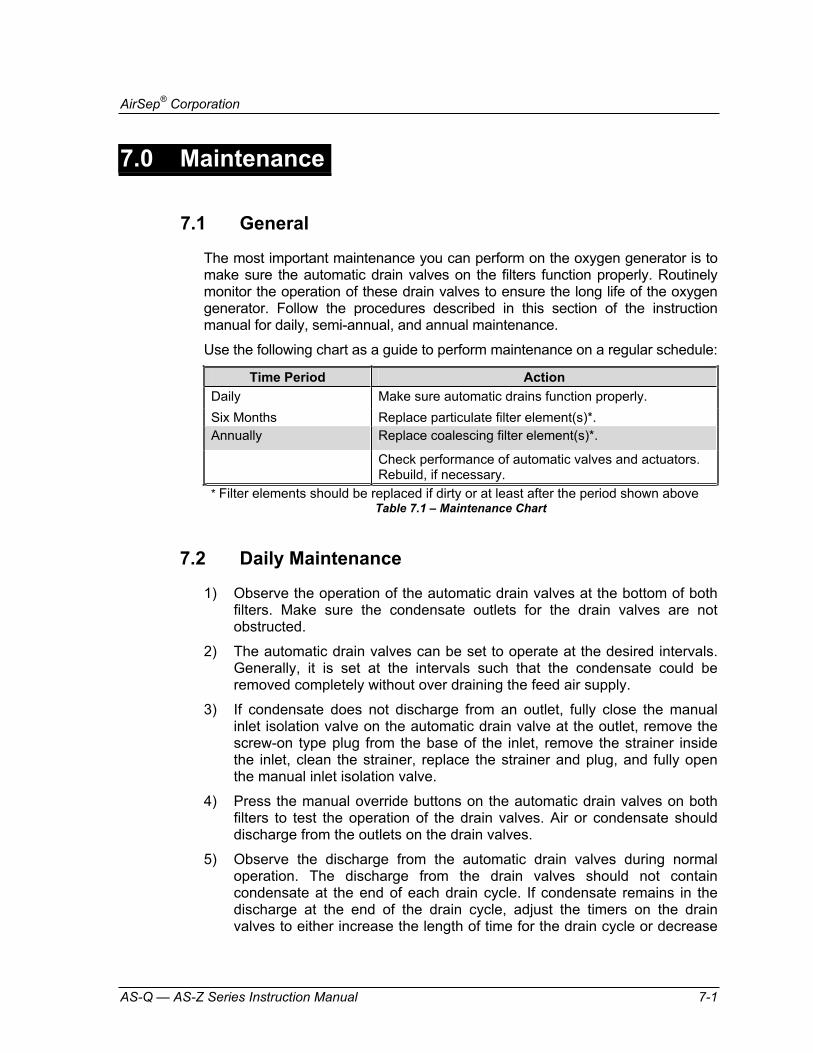
The most important maintenance you can perform on the oxygen generator is to make sure the automatic drain valves on the filters function properly. Routinely monitor the operation of these drain valves to ensure the long life of the oxygen generator. Follow the procedures described in this section of the instruction manual for daily, semi-annual, and annual maintenance.
Use the following chart as a guide to perform maintenance on a regular schedule:
Time Period ActionDaily Make sure automatic drains function properly. Six Months Replace particulate filter element(s)*. Annually Replace coalescing filter element(s)*.
Check performance of automatic valves and actuators. Rebuild, if necessary.
* Filter elements should be replaced if dirty or at least after the period shown aboveTable 7.1 – Maintenance Chart
7.2 Daily Maintenance
1) Observe the operation of the automatic drain valves at the bottom of both filters. Make sure the condensate outlets for the drain valves are not obstructed.
2) The automatic drain valves can be set to operate at the desired intervals. Generally, it is set at the intervals such that the condensate could be removed completely without over draining the feed air supply.
3) If condensate does not discharge from an outlet, fully close the manual inlet isolation valve on the automatic drain valve at the outlet, remove the screw-on type plug from the base of the inlet, remove the strainer inside the inlet, clean the strainer, replace the strainer and plug, and fully open the manual inlet isolation valve.
4) Press the manual override buttons on the automatic drain valves on both filters to test the operation of the drain valves. Air or condensate should discharge from the outlets on the drain valves.
5) Observe the discharge from the automatic drain valves during normal operation. The discharge from the drain valves should not contain condensate at the end of each drain cycle. If condensate remains in the discharge at the end of the drain cycle, adjust the timers on the drain valves to either increase the length of time for the drain cycle or decrease

AirSep® Corporation
7-2 AS-Q — AS-Z Series Instruction Manual
the interval between drain cycles until the discharge at the end of the drain cycle is free of condensate.
To adjust the time for the drain cycle, use the lower knob on the timer on the drain valve. Rotate the knob counterclockwise to decrease the time or clockwise to increase the time.
To adjust the interval between drain cycles, use the upper knob on the timer. Rotate the knob counterclockwise to decrease the interval or clockwise to increase the interval.
Excess operation of the automatic drain valves may decrease the quantity of feed air enough to impair the performance of the oxygen generator. Set the timers to allow the drain valves to operate long enough to drain all the condensate from the discharge but not long enough to allow air-only discharge for more than a few seconds.
7.3 Semi-Annual Maintenance
Perform the semi-annual maintenance procedure only with the oxygen generator shut down.
Do not attempt to remove the filter bowls until the filter assembly fully depressurizes.
7.3.1 Particulate Filter Replacement The particulate filter removes rust, pipe scale, and other foreign particles from the feed air. It also separates most of the condensed water and oil from the air. Use the following procedure to replace the particulate filter element(s) at least every six months or as required:
The expected life of the particulate filter is approximately six months. Its purpose is to protect and extend the life of the coalescing filter. The life of the particulate filter depends on air and piping quality. The particulate filter has a rating of 5 microns.
1) Follow all steps in Section 6.6 — Extended Shutdown.
2) Make sure that manual valves on either side of the filter assembly are closed.
AirSep® Corporation
AS-Q — AS-Z Series Instruction Manual 7-3
3) Press the manual override button on the automatic drains of the filters to depressurize the filter assembly.
4) Disconnect, tag, and lockout electrical power to the drain valve.
5) Remove the timer and conduit from the drain valve on the bottom of the filter bowl. The timer attaches to the valve body with one screw.
6) Slowly loosen, but do not remove, all eight-socket head cap screws that hold the bowl to the filter body to make sure the bowl fully depressurizes before removal.
7) Remove the eight-socket head cap screws that hold the bowl to the filter body to disconnect the bowl. An empty filter bowl indicates proper drain system operation.
The old particulate filter element(s) cannot be cleaned. You must replace it (them) with (a) new element(s).
8) To remove the particulate filter element(s), disconnect the retainer nut from under the element(s).
9) Place the new element(s) where the old one(s) was (were) located, and reconnect the retainer nut.
10) Wash the bowl in warm, soapy water, and rinse.
11) Reconnect the filter bowl.
12) Reconnect the timer and conduit assembly to the drain valve body.
13) Remove the lockout and tag, and provide electrical power to the oxygen generator.
14) Make sure the MANUAL FEED #2 valve (V-2) remains fully closed.
15) Fully open the MANUAL FEED #1 valve (V-1) to pressurize the particulate filter.
16) Apply soapy water to check for leaks on all fittings loosened during the replacement procedure.
17) Press the manual override button on the automatic drain valve on the particulate filter and make sure the exhaust contains no liquid.
18) Follow all steps in Section 6.2 — Initial Start-Up.
AirSep® Corporation
7-4 AS-Q — AS-Z Series Instruction Manual
7.4 Annual Maintenance
Perform the annual maintenance procedure only with the oxygen generator shut down.
Do not attempt to remove the filter bowls until the filter assembly fully depressurizes.
7.4.1 Maintenance of Automatic Valves If possible, the functioning of the valves should be checked daily.
1) Check all moving parts on the oxygen generator (automatic valves and pneumatic actuators) for any indication of wear. Replace all worn parts.
2) Make sure all automatic valves operate properly. Make sure all connections remain tight and that each valve opens and closes properly.
3) If a valve operates slowly (two seconds or more), repair or rebuild the solenoid valve or valve actuator. Refer to the valve manufacturer’s literature in Appendix D of this instruction manual for more information.
4) Check all automatic valves and pneumatic actuators for leaks. Use soapy water to check leaks at the valve stems. If the valves or actuators leak, tighten or replace the packing.
Do not over-tighten packing bolts on air operated valves.
7.4.2 Coalescing Filter Replacement The coalescing filter causes oil “fog” particles and water vapor that pass through the particulate filter to collide (coalesce) and form larger droplets, which fall to the bottom of the filter bowl. Replace the coalescing filter element(s) annually.

AirSep® Corporation
AS-Q — AS-Z Series Instruction Manual 7-5
The expected life of the coalescing filter is approximately one year with proper maintenance of the particulate filter. The coalescing filter has a rating of 0.01 microns.
1) Follow all steps in Section 6.6 — Extended Shutdown.
2) Make sure that manual valves on either side of the filter assembly are closed.
3) Press the manual override button on the automatic drains of the filters to depressurize the filter assembly.
4) Disconnect, tag, and lockout electrical power to the drain valve.
5) Remove the timer and conduit from the drain valve on the bottom of the filter bowl. The timer attaches to the valve body with one screw.
6) Slowly loosen, but do not remove, all eight socket head cap screws that hold the bowl to the filter body to make sure the bowl fully depressurizes before removal.
7) Remove the eight socket head cap screws that hold the bowl to the filter body to disconnect the bowl.
An empty filter bowl indicates proper drain system operation.
The old coalescing filter element(s) cannot be cleaned. You must replace it (them) with (a) new element(s).
8) To remove the coalescing filter element(s), disconnect the retainer nut from under the element(s).
9) Place the new element(s) where the old one(s) was (were) located, and reconnect the retainer nut.
10) Wash the bowl in warm, soapy water, and rinse.
11) Reconnect the filter bowl.
12) Reconnect the timer and conduit assembly to the drain valve body.
13) Remove the lockout and tag, and provide electrical power to the oxygen generator.
14) Make sure the MANUAL FEED #2 valve (V-2) remains fully closed.
15) Fully open the MANUAL FEED #1 valve (V-1) to pressurize the particulate filter.
16) Apply soapy water to check for leaks on all fittings loosened during the replacement procedure.

AirSep® Corporation
7-6 AS-Q — AS-Z Series Instruction Manual
17) Press the manual override button on the automatic drain valve on the coalescing filter and make sure the exhaust contains no liquid.
18) Follow all steps in Section 6.2 — Initial Start-Up.

AirSep® Corporation
AS-Q — AS-Z Series Instruction Manual 8-1
8.0 Troubleshooting
8.1 General
The oxygen generator contains electrical parts that can produce an electrical shock hazard if not handled properly. To prevent electrical shock, use extreme care when you service the oxygen generator. Only trained personnel may open the oxygen generator.
The AirSep PSA Oxygen Generator is pressurized during normal operation. You must depressurize the oxygen generator before you attempt any repairs.
To depressurize the oxygen generator safely, use the following procedure:
1) Fully close the MANUAL FEED #2 valve (V-2).
2) Fully close the manual valve at the inlet and the outlet of the oxygen receiver and the valve on the sample oxygen flow connection to the oxygen analyzer panel.
3) Press the ‘Start’ icon on the Oxygen Generator Touch Screen.
4) Set the ‘AUTO/MAN’ icon on the Oxygen Generator Screen to MANUALmode.
5) Allow the oxygen generator to run until the CYCLE PRESSURE, BED A, and BED B gauges register 0 psig, then press the ‘Stop’ icon on the Main System Control Screen.
6) If the gauges do not decrease to 0 psig, press the ‘Stop’ icon on the Main System Control Screen, and contact your distributor.
7) If instructed by your distributor to contact AirSep Corporation, contact the AirSep Commercial Products Service Department by telephone Monday through Friday between 7:30 a.m. and 4:30 p.m. Eastern Time. In the USA or Canada, call 1-800-320-0303. Outside the USA or Canada, call (716) 691-0202. Send fax inquiries anytime to (716) 691-1255. Address written inquiries to AirSep Corporation, 260 Creekside Drive, Buffalo, NY 14228-2075 USA, Attention: Commercial Products Service Department.
8) Fully close the MANUAL FEED #1 valve (V-1).
9) Depressurize the filter assembly by pressing the manual override button on the automatic drains for the filters.

AirSep® Corporation
8-2 AS-Q — AS-Z Series Instruction Manual
8.2 Troubleshooting Chart
Use the following chart as a guide to troubleshoot the oxygen generator.
Problem Probable Cause SolutionOxygen generator does not cycle. No electrical power to
control cabinet. Provide electrical power to control cabinet.
Low Feed air pressure Ensure feed air pressure is more than the minimum feed air pressure specified in the Appendix A and then press the ‘ALARM RESET’ icon before starting the generator.
Oxygen generator does not cycle even after pressing the ‘START’ icon. Feed air pressure exceedsminimum feed air pressure specified in Appendix A of this instruction manual.
Oxygen generator controls not reset after unexpected shutdown.
Press the ‘ ALARM RESET’ icon.
Blown fuse(s) or tripped circuit breaker for PLC.
Replace fuse(s) or reset the circuit breaker.
Oxygen generator does not cycle. ‘AUTO/MAN’ icon is in AUTOmode.
‘START’ icon is not pressed.
Refer to Section 6.2 — Initial Start-Up or Section 6.5 — Normal Start-Up, as appropriate, to start oxygen generator.
Oxygen generator in standby.
Oxygen generator restarts automatically when oxygen receiver depressurizes.
Oxygen generator does not cycle when OXYGEN RECEIVER PRESSURE gauge registers less than the minimum pressure specified in this instruction manual. ‘AUTO/MAN’ icon is in AUTO position.
PT-4 defective or not calibrated.
Calibrate the pressure transducer PT-4. Replace PT-4 if defective.
‘START’ icon is not pressed
Press the ‘START’ icon.
Loose wire in the control panel.
Repair loose connections.
PLC defective. Replace PLC.
Oxygen generator cycles continuously. OXYGEN RECEIVER PRESSURE gauge registers pressure greater than the
PT-4 defective or not calibrated.
Calibrate the pressure transducer PT-4. Replace PT-4 if defective.

AirSep® Corporation
AS-Q — AS-Z Series Instruction Manual 8-3
maximum oxygen receiver pressure specified in this instruction manual. ‘AUTO/MAN’ icon in AUTO position.
PRODUCT SAMPLE valve not fully closed.
Fully close PRODUCT SAMPLE valve.
Leak on hoses or piping, or on fittings that connect oxygen generator to oxygen receiver.
Use soapy water, to check hoses, piping, and fittings between oxygen generator and oxygen receiver. Check all tube and pipe fittings inside control cabinet with soapy water. You can hear most leaks when area is quiet. Repair leaks as necessary.
When oxygen generator cycles, feed air pressure is less than maximum cycle pressure specified in the Appendix of this instruction manual.
Restriction in feed air piping.
Remove restriction from feed air piping.
Partially open valve between air compressor and oxygen generator.
Make sure manual valves between air compressor and oxygen generator, if any, are either fully closed or fully open, depending on purpose of valves.
Feed air piping or connection smaller in diameter than required.
Use larger diameter piping or connection to decrease pressure drop.
Air compressor malfunction.
Check air compressor. Service as necessary.
Low purity oxygen. Waste gas in oxygen receiver during initial start-up, start-up after servicing, or start-up after an extended shutdown.
Vent oxygen receiver as described in Section 6.2 — Initial Start-up.
Oxygen generator output overdrawn.
Fully close PRODUCT SAMPLE valve on product manifold and oxygen vent valve, if any, on oxygen receiver and check the purity.
Automatic valves make unusual noises, or do not fully open or close,
Make sure valve actuators receive adequate instrument

AirSep® Corporation
8-4 AS-Q — AS-Z Series Instruction Manual
or do not open or close at approximately the same speed (1–2 secs)
air pressure for proper operation.
Use soapy water to check for leaks at valve stems, hoses, actuators, or solenoid valves. Repair leaks as necessary.
Make sure solenoid coils energize properly.
Make sure actuator to valve couplings are tight and positioned properly on valve stems, and that valve stems actually turn.
Replace or Rebuild actuators or valves as necessary.

AirSep® Corporation
AS-Q — AS-Z Series Instruction Manual A-1
A Appendix: Technical Data
Specifications Data in this section refers to the standard AS-Q through AS-Z model oxygen generators. The oxygen generators may use feed air at specifications outside those shown; however, use of such feed air may require modification of the oxygen generators at the AirSep Corporation factory to ensure the product oxygen meets the design specifications. Consult your sales representative to determine whether your oxygen generator requires modifications for your application.
Provide proper voltage from a grounded outlet to the oxygen generator. Main power supply voltage fluctuation must not exceed 10% of the nominal supply voltage.

AirSep® Corporation
A-2 AS-Q — AS-Z Series Instruction Manual
AS-Q
Oxygen output: 2500 - 2800 SCF/hr at 45 psig* (max.)**
Oxygen purity: 93% Nominal
Oxygen dew point: -73°C -100°F
Approximate weight: 8620 lbs 3910 kg
Dimensions 61 x 112 x 140 in. (L x W x H) 154 x 286 x 355 cm (L x W x H)
Feed Air Requirements
Pressure: 90 psig (min.) 620 kPa (min.)
Temperature: 50°C (max.) 122°F (max.)
Power requirements: 120 V~±10%, 50/60 Hz, Single Phase, 3A 240 V~±10%, 50/60 Hz, Single Phase, 1A
Other Specifications: Pollution degree: 2
Installation category: II
Altitude: 2000 m
*SCF (standard cubic foot) gas measured at 1 atmosphere and 70°F. ** Pressures up to 65 psig available.

AirSep® Corporation
AS-Q — AS-Z Series Instruction Manual A-3
AS-R
Oxygen output: 3000 - 3700 SCF/hr at 45 psig* (max.)**
Oxygen purity: 93% Nominal
Oxygen dew point: -73°C -100°F
Approximate weight: 12405 lbs 5627 kg
Dimensions 74 x 114 x 157 in. (L x W x H) 187 x 290 x 398 cm (L x W x H)
Feed Air Requirements
Pressure: 90 psig (min.) 620 kPa (min.)
Temperature: 50°C (max.) 122°F (max.)
Power requirements: 120 V~±10%, 50/60 Hz, Single Phase, 3A 240 V~±10%, 50/60 Hz, Single Phase, 1A
Other Specifications: Pollution degree: 2
Installation category: II
Altitude: 2000 m
*SCF (standard cubic foot) gas measured at 1 atmosphere and 70°F. ** Pressures up to 65 psig available.

AirSep® Corporation
A-4 AS-Q — AS-Z Series Instruction Manual
AS-W
Oxygen output: 4000 - 4600 SCF/hr at 45 psig* (max.)**
Oxygen purity: 93% Nominal
Oxygen dew point: -73°C -100°F
Approximate weight: 15990 lbs 7253 kg
Dimensions 88 x 114 x 197 in. (L x W x H) 223 x 289 x 501 cm (L x W x H)
Feed Air Requirements
Pressure: 90 psig (min.) 620 kPa (min.)
Temperature: 50°C (max.) 122°F (max.)
Power requirements: 120 V~±10%, 50/60 Hz, Single Phase, 3A 240 V~±10%, 50/60 Hz, Single Phase, 1A
Other Specifications: Pollution degree: 2
Installation category: II
Altitude: 2000 m
*SCF (standard cubic foot) gas measured at 1 atmosphere and 70°F. ** Pressures up to 65 psig available.

AirSep® Corporation
AS-Q — AS-Z Series Instruction Manual A-5
AS-Z
Oxygen output: 5000 - 5500 SCF/hr at 45 psig* (max.)**
Oxygen purity: 93% Nominal
Oxygen dew point: -73°C -100°F
Approximate weight: 19460 lbs 8827 kg
Dimensions 90 x 116 x 220 in. (L x W x H) 229 x 294 x 560 cm (L x W x H)
Feed Air Requirements
Pressure: 90 psig (min.) 620 kPa (min.)
Temperature: 50°C (max.) 122°F (max.)
Power requirements: 120 V~±10%, 50/60 Hz, Single Phase, 3A 240 V~±10%, 50/60 Hz, Single Phase, 1A
Other Specifications: Pollution degree: 2
Installation category: II
Altitude: 2000 m
*SCF (standard cubic foot) gas measured at 1 atmosphere and 70°F. ** Pressures up to 65 psig available.

AirSep® Corporation
A-6 AS-Q — AS-Z Series Instruction Manual
Typical Operating Data*
Description
Operating Pressure
(psig)
Operating Pressure
(kPa) Feed air low pressure shutdown level 35 241
Minimum feed air pressure 90 620 Maximum feed air pressure 125 862 Typical Adsorber A or B max. operating pressure
75-80
517-552
Table A.1 – Operating Pressures
Description Length of Interval
Interval during which drain valve operates 5 seconds
Interval between periods of drain valve operation 10 minutes
Table A.2 - Drain Valve Operating Intervals
Typical Feed Air Regulator Setting (If supplied) 75-77 psig 517 – 531 kPa
Auto-standby feature: Standby activates at:
75 psig (Product Oxygen
Pressure) 517 kPa
Standby resets at: 68 psig (Product Oxygen
Pressure) 469 kPa
Oxygen Analyzer Board pressure regulator setting 1 psig 7 kPa
Low oxygen purity alarm 89% Low Oxygen Purity Shutdown or Low Purity Cut-off valve (If supplied) set point
87%
High bed pressure alarm 83 psig 572 kPa High bed pressure shutdown 85 psig 586 kPa
Table A.3 - Set points
*Data may vary as per the customer’s requirements.

AirSep® Corporation
AS-Q — AS-Z Series Instruction Manual A-7
Drawings

AirSep® Corporation
A-8 AS-Q — AS-Z Series Instruction Manual

AirSep® Corporation
AS-Q — AS-Z Series Instruction Manual A-9
Figure A.1: General Arrangement Drawing – AS-Q

AirSep® Corporation
A-10 AS-Q — AS-Z Series Instruction Manual
Figure A.2: General Arrangement Drawing – AS-R

AirSep® Corporation
AS-Q — AS-Z Series Instruction Manual A-11
Figure A.3: General Arrangement Drawing – AS-W

AirSep® Corporation
A-12 AS-Q — AS-Z Series Instruction Manual
Figure A.4: General Arrangement Drawing – AS-Z
AirSep® Corporation
AS-Q — AS-Z Series Instruction Manual A-13
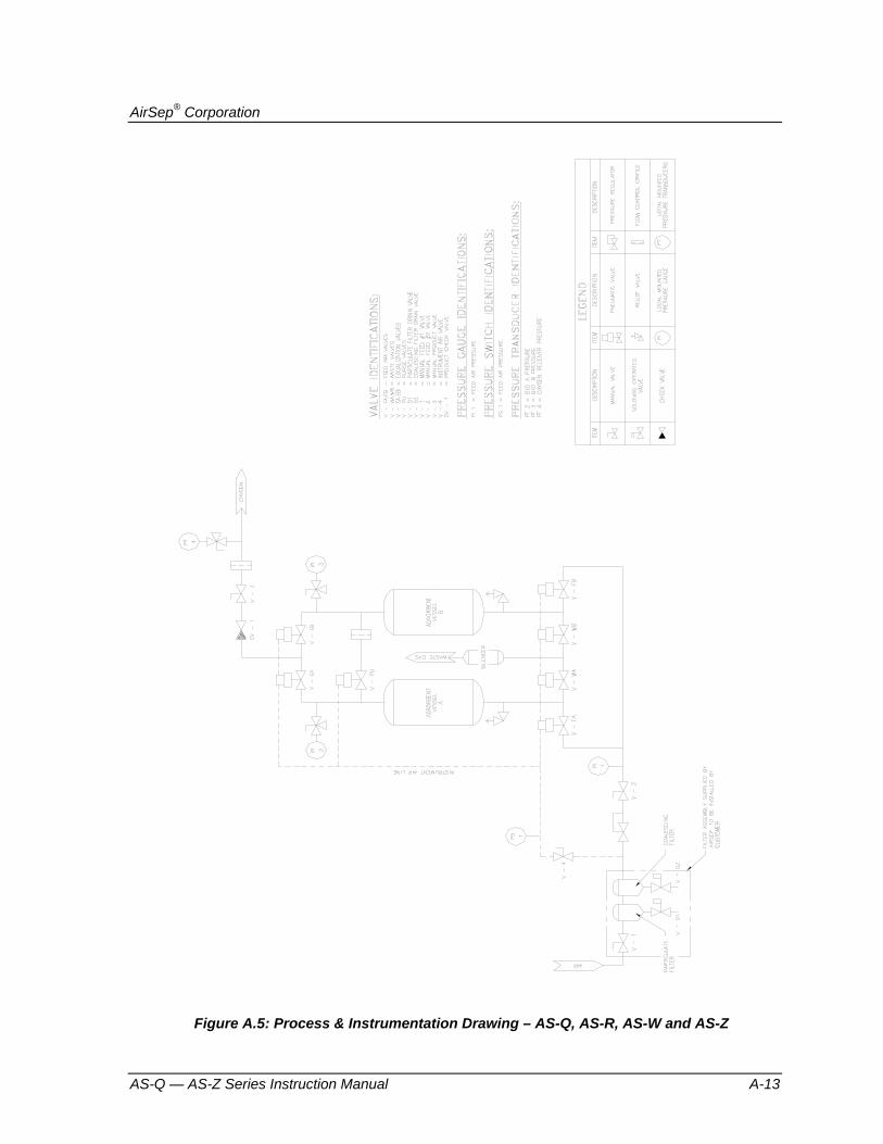
Figure A.5: Process & Instrumentation Drawing – AS-Q, AS-R, AS-W and AS-Z

AirSep® Corporation
A-14 AS-Q — AS-Z Series Instruction Manual
Figure A.6: Electrical Schematic - I

AirSep® Corporation
AS-Q — AS-Z Series Instruction Manual A-15
Figure A.7: Electrical Schematic - II

AirSep® Corporation
A-16 AS-Q — AS-Z Series Instruction Manual
Figure A.8: Electrical Schematic - III

AirSep® Corporation
AS-Q — AS-Z Series Instruction Manual A-17
Figure A.9: Electrical Schematic - IV


AirSep® Corporation
AS-Q — AS-Z Series Instruction Manual B-1
B Appendix: Warranty/Returns
Product Warranty
AirSep Corporation (“AirSep”) warrants to the party purchasing from AirSep (the “original purchaser”) the PSA oxygen generator to be free from defect in parts and workmanship for one year from the date of start-up, not to exceed eighteen (18) months from the date of shipment to the original purchaser, under normal use, maintenance and operation*. TO THE EXTENT PERMITTED UNDER APPLICABLE LAW, ALL WARRANTIES WITH RESPECT TO SUCH UNIT SHALL ONLY EXTEND TO AND BE FOR THE BENEFIT OF THE ORIGINAL PURCHASER AND SHALL NOT BE ASSIGNABLE TO, EXTEND TO OR BE FOR THE BENEFIT OF ANY OTHER PARTY. AirSep’s obligations under this warranty are limited, at AirSep’s option, to the repair, replacement or refunding the purchase price of any such unit of equipment (or part thereof) found by AirSep to be defective in parts or workmanship; provided, however, that AirSep shall have no obligation hereunder with respect to a defective part unless it receives written notice of such defect prior to the expiration of the applicable warranty period as referenced above.
Each unit of equipment for which a warranty claim is asserted shall, at the request of AirSep, be returned on a prepaid basis with proof of purchase date to the AirSep factory specified by AirSep at the expense of the original purchaser. Replacement parts shall be warranted as stated above for the unexpired portion of the original warranty. This warranty does not extend to any unit or part subjected to misuse (at AirSep’s sole determination), accident, improper maintenance or application, or which has been repaired or altered outside of the AirSep factory without the express prior written authorization of AirSep.
Notwithstanding anything to the contrary contained herein, during the applicable warranty period, as specified above, AirSep will pay the cost of return freight charges to the original purchaser, provided an authorized AirSep representative approved return of the unit or parts, for any equipment found by AirSep to be defective. For warranty repairs performed during the first 90 days from the date of invoice, AirSep will pay freight both ways. After the applicable parts warranty period has expired, the original purchaser is responsible for freight both ways.
* Please refer to the appropriate product documentation for applicable installation and operating requirements.

AirSep® Corporation
B-2 AS-Q — AS-Z Series Instruction Manual
Limits of Liability
THE FOREGOING WARRANTY IS THE ONLY WARRANTY MADE BY AIRSEP WITH RESPECT TO THE EQUIPMENT (OR ANY PART THEREOF) AND IS IN LIEU OF ANY OTHER WARRANTY, EXPRESSED OR IMPLIED, IN FACT OR IN LAW, INCLUDING WITHOUT LIMITATION ANY WARRANTIES OF MERCHANTABILITY OR FITNESS FOR ANY PARTICULAR PURPOSE. IT IS EXPRESSLY UNDERSTOOD THAT THE SOLE AND EXCLUSIVE REMEDY FOR ANY DEFECT IN PARTS OR WORKMANSHIP IS LIMITED TO ENFORCEMENT OF AIRSEP’S OBLIGATIONS AS SET FORTH ABOVE, AND AIRSEP SHALL NOT BE LIABLE TO ORIGINAL PURCHASER OR ANY OTHER PARTY FOR LOSS OF USE OF THE EQUIPMENT, LOST PROFITS OR FOR ANY OTHER SPECIAL, INDIRECT, INCIDENTAL, OR CONSEQUENTIAL DAMAGES (EVEN IF AIRSEP HAS BEEN ADVISED OF THE POSSIBILITY OF SUCH DAMAGES).
AirSep oxygen generators are sold for use in industrial applications only. Contact AirSep Corporation or an authorized AirSep Corporation representative before you use this unit for any medical application.
Returning the Oxygen Generator or a Component for Service
If the oxygen generator or a defective part requires service, contact your distributor. If instructed by your distributor to contact AirSep Corporation, follow the procedure below to return the oxygen generator or a component for service or credit.
1) Obtain a Return Goods Authorization (RGA) number from the AirSep Commercial Products Service Department. (Refer to Section 8.0 — Troubleshooting for information about contacting AirSep Corporation.) Before you call for service assistance, have the following information readily available:
Oxygen Generator Model
Serial Number
Hours of Use
Invoice Date
AirSep Corporation issues no credit for any warranted item until you present the model number, serial number, and invoice date of the oxygen generator, and defective part is returned to AirSep Corporation.

AirSep® Corporation
AS-Q — AS-Z Series Instruction Manual B-3
2) Write the RGA number clearly on the outside of the shipping container.
AirSep Corporation accepts no item(s) for service or credit unless prior written authorization was issued by AirSep Corporation.
3) Return item(s) in their original packaging material. Pack merchandise for a safe return. AirSep Corporation assumes no responsibility for damage that occurs in transit. Any damage to the oxygen generator or a component because of failure to follow this procedure is the sole responsibility of the customer.
Return item(s) on a freight prepaid basis only.


AirSep® Corporation
AS-Q — AS-Z Series Instruction Manual C-1
C Appendix: Parts List
Use the following lists to order parts or rebuild kits for the oxygen generator. To order, please contact your distributor. If instructed by your distributor to contact AirSep Corporation, contact the AirSep Commercial Products Service Department as described in Section 8.0 — Troubleshooting. If the list does not contain the part you require, please provide a precise description of the part when you call.
Item Qty Part # 8,000 Hour Kit/1 Year Prefilter Element, FRP-95-508, 1/4000 hours 2 FI065-1 Microalescer Element, MTP-95-562, 1/8000 hours 1 FI022-1 16,000 Hour Kit/2 Year Prefilter Element, FRP-95-508, 1/4000 hours 4 FI065-1 Microalescer Element, MTP-95-562, 1/8000 hours 2 FI022-1 Feed:Valve Assy,Butterfly,3",w/VPVL200DAB act VA402-3 Asco Valve SC8551A1MS 2 VA311-2 Jamesbury Actuator Rebuild Kit, RKP155 2 VA412-2 Jamesbury Butterfly Kit, RKW352XZ 2 VA414-3 Waste:Valve Assy,Butterfly,4",w/VPVL250DAB act VA403-4 Asco Valve SC8551A1MS 2 VA311-2 Jamesbury Actuator Rebuild Kit, RKP156 2 VA412-3 Jamesbury Butterfly Kit, RKW353XZ 2 VA414-4 EqualizationValve Assy,Butterfly,3",w/VPVL200DAB act VA402-3 Asco Valve SC8551A1MS 2 VA311-2 Jamesbury Actuator Rebuild Kit, RKP155 2 VA412-2 Jamesbury Butterfly Kit, RKW352XZ 2 VA414-3 Purge:Valve Assy, Ball valve 1 1/2" VPVL200DAB act VA401-3 Asco valve SC8551AIMS 1 VA311-2 Jamesbury Actuator rebuild kit RKP155 1 VA412-2 Jamesbury Ball kit RKN359XT 1 VA414-2 Emergency spares PLC Timer Allem Bradley 1200 Micrologic 1762-L24BWA CM102-2 PLC Timer Allem Bradley Analog input 1762-1F4 CM103-1 PLC Timer Allem Bradley Panel view plus 600 CM104-2 Actuator Jamesbury VPVL200DAB VA411-2 Actuator Jamesbury VPVL250DAB VA411-3 Drain Valve, 115/60Hz DA003-1 Muffler Elements 2" MU057-1

AirSep® Corporation
C-2 AS-Q — AS-Z Series Instruction Manual
Check Valve 1" VA161-1 Transducer MI224-1 MagnaLube PS211-1

AirSep® Corporation
AS-Q — AS-Z Series Instruction Manual D-1
D Appendix: Component Literature
Programmable Logic Controller Allen Bradley MicroLogix™ 1200 Programmable Logic Controller (PLC)
Installation Instructions
Allen Bradley MicroLogix™ Analog Input Module
Installation Instructions
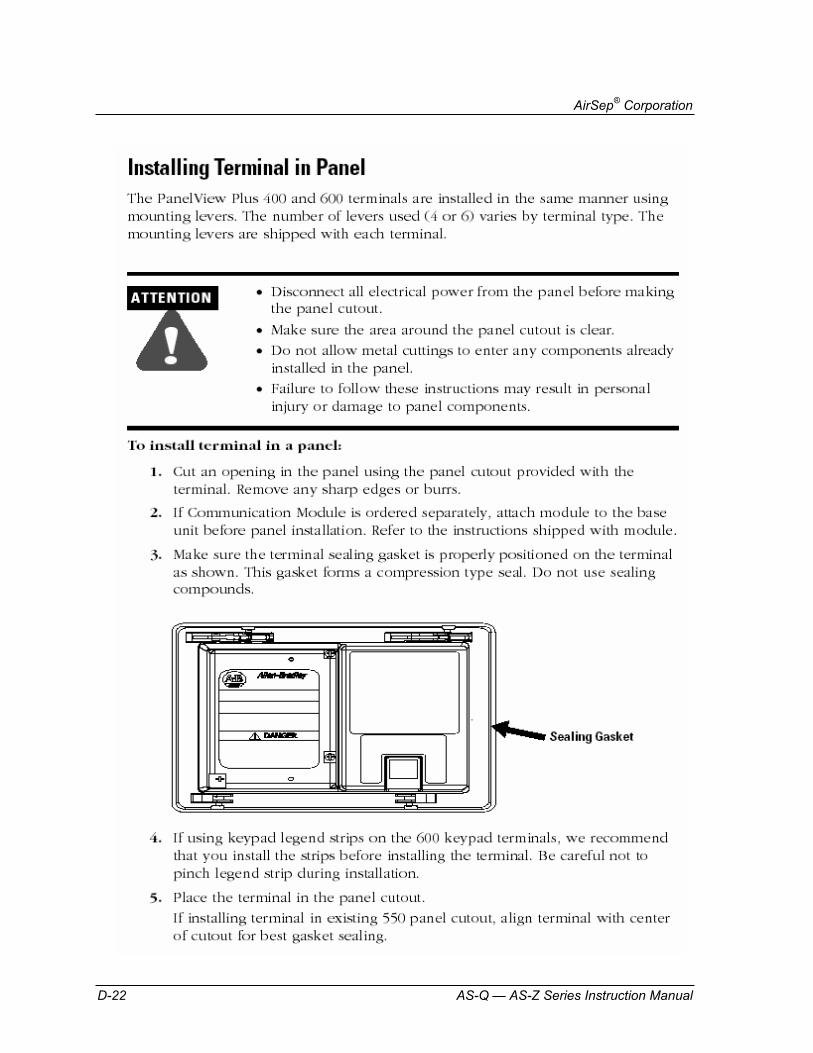
Allen BradleyPanelView Plus 400 and 600 Terminals Installation Instructions
Filters Wilkerson Filter Models F35, F36, and F37
Installation and Maintenance Sheet
Wilkerson Filter Models M35, M36, and M37
Installation and Maintenance Sheet
Wilkerson Filter Model F43
Installation and Maintenance Sheet
Wilkerson Filter Models M43 & M45
Installation and Maintenance Sheet
Pressure Transducer Measurement Specialties, Inc. – MSI MSP-300 Stainless Steel Isolated Pressure
Transducer
Measurement Specialties, Inc. – MSI MSP-300-150-P-4-N-X-XXX Pressure
Transducer Drawing

AirSep® Corporation
D-2 AS-Q — AS-Z Series Instruction Manual
Valves and Actuators Neles-Jamesbury IMO 308 Model C Wafer-Sphere® Butterfly Valves
Installation, Maintenance and OperatingInstructions
Motivair Automatic Condensate Removal Valve EDM 20-1 Electronic Timer-Solenoid
Technical Data
ASCO 4-Way 2 Position Single Solenoid Valves — ¼ NPT Pressure Series 8551
Installation and Maintenance Instructions
Jamesbury Double-opposed Piston Actuators IMO-528
Installation, Maintenance and OperatingInstructions
Pressure Switch Allen-Bradley Bulletin 836 Style C
Instruction Sheet
Miscellaneous Gasket Material for Oxygen Service Durabla Manufacturing Company Durabla Black Compressed Gasket Material
Material Safety Data Sheets

AirSep® Corporation
AS-Q — AS-Z Series Instruction Manual D-3

AirSep® Corporation
D-4 AS-Q — AS-Z Series Instruction Manual

AirSep® Corporation
AS-Q — AS-Z Series Instruction Manual D-5

AirSep® Corporation
D-6 AS-Q — AS-Z Series Instruction Manual
AirSep® Corporation
AS-Q — AS-Z Series Instruction Manual D-7

AirSep® Corporation
D-8 AS-Q — AS-Z Series Instruction Manual

AirSep® Corporation
AS-Q — AS-Z Series Instruction Manual D-9

AirSep® Corporation
D-10 AS-Q — AS-Z Series Instruction Manual

AirSep® Corporation
AS-Q — AS-Z Series Instruction Manual D-11


AirSep® Corporation
AS-Q — AS-Z Series Instruction Manual D-13

AirSep® Corporation
D-14 AS-Q — AS-Z Series Instruction Manual

AirSep® Corporation
AS-Q — AS-Z Series Instruction Manual D-15

AirSep® Corporation
D-16 AS-Q — AS-Z Series Instruction Manual

AirSep® Corporation
AS-Q — AS-Z Series Instruction Manual D-17

AirSep® Corporation
D-18 AS-Q — AS-Z Series Instruction Manual

AirSep® Corporation
AS-Q — AS-Z Series Instruction Manual D-19

AirSep® Corporation
D-20 AS-Q — AS-Z Series Instruction Manual

AirSep® Corporation
AS-Q — AS-Z Series Instruction Manual D-21
AirSep® Corporation
D-22 AS-Q — AS-Z Series Instruction Manual

AirSep® Corporation
AS-Q — AS-Z Series Instruction Manual D-23

AirSep® Corporation
D-24 AS-Q — AS-Z Series Instruction Manual

AirSep® Corporation
AS-Q — AS-Z Series Instruction Manual D-25

AirSep® Corporation
D-26 AS-Q — AS-Z Series Instruction Manual

AirSep® Corporation
AS-Q — AS-Z Series Instruction Manual D-27

AirSep® Corporation
D-28 AS-Q — AS-Z Series Instruction Manual

AirSep® Corporation
AS-Q — AS-Z Series Instruction Manual D-29
AirSep® Corporation
D-30 AS-Q — AS-Z Series Instruction Manual

AirSep® Corporation
AS-Q — AS-Z Series Instruction Manual D-31

AirSep® Corporation
D-32 AS-Q — AS-Z Series Instruction Manual

AirSep® Corporation
AS-Q — AS-Z Series Instruction Manual D-33

AirSep® Corporation
D-34 AS-Q — AS-Z Series Instruction Manual

AirSep® Corporation
AS-Q — AS-Z Series Instruction Manual D-35

AirSep® Corporation
D-36 AS-Q — AS-Z Series Instruction Manual

AirSep® Corporation
AS-Q — AS-Z Series Instruction Manual D-37
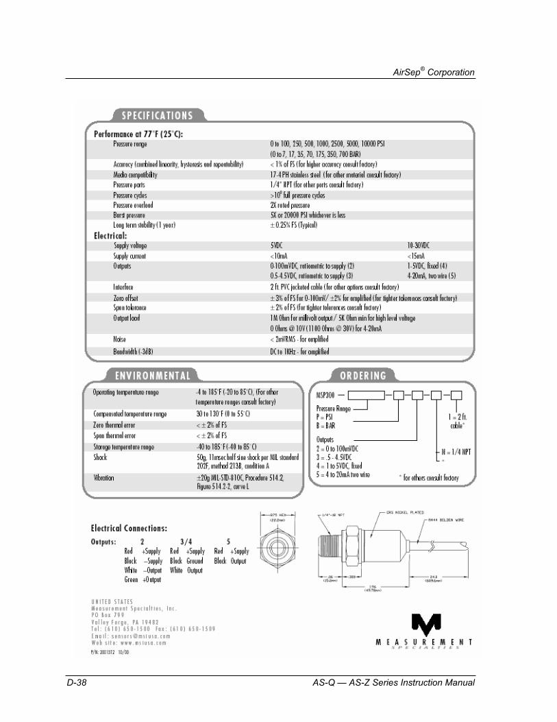
AirSep® Corporation
D-38 AS-Q — AS-Z Series Instruction Manual

AirSep® Corporation
AS-Q — AS-Z Series Instruction Manual D-39


AirSep® Corporation
AS-Q — AS-Z Series Instruction Manual D-41

AirSep® Corporation
D-42 AS-Q — AS-Z Series Instruction Manual

AirSep® Corporation
AS-Q — AS-Z Series Instruction Manual D-43

AirSep® Corporation
D-44 AS-Q — AS-Z Series Instruction Manual

AirSep® Corporation
AS-Q — AS-Z Series Instruction Manual D-45

AirSep® Corporation
D-46 AS-Q — AS-Z Series Instruction Manual

AirSep® Corporation
AS-Q — AS-Z Series Instruction Manual D-47

AirSep® Corporation
D-48 AS-Q — AS-Z Series Instruction Manual

AirSep® Corporation
AS-Q — AS-Z Series Instruction Manual D-49
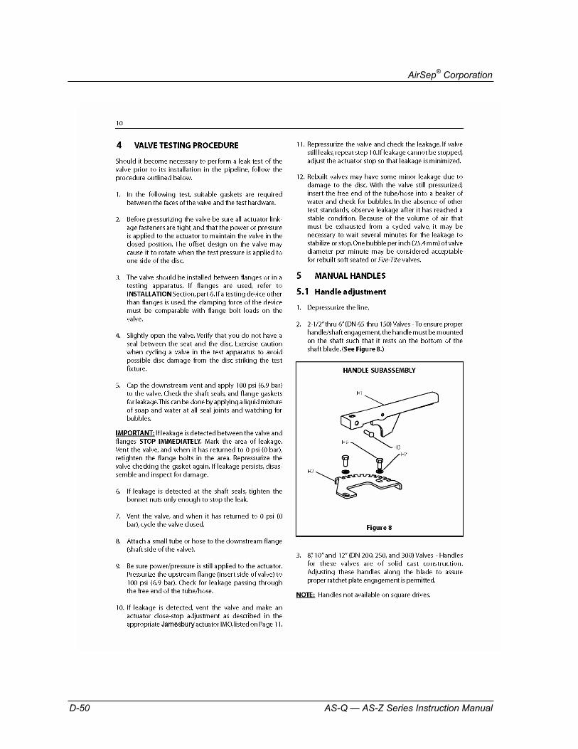
AirSep® Corporation
D-50 AS-Q — AS-Z Series Instruction Manual

AirSep® Corporation
AS-Q — AS-Z Series Instruction Manual D-51

AirSep® Corporation
D-52 AS-Q — AS-Z Series Instruction Manual

AirSep® Corporation
AS-Q — AS-Z Series Instruction Manual D-53

AirSep® Corporation
D-54 AS-Q — AS-Z Series Instruction Manual
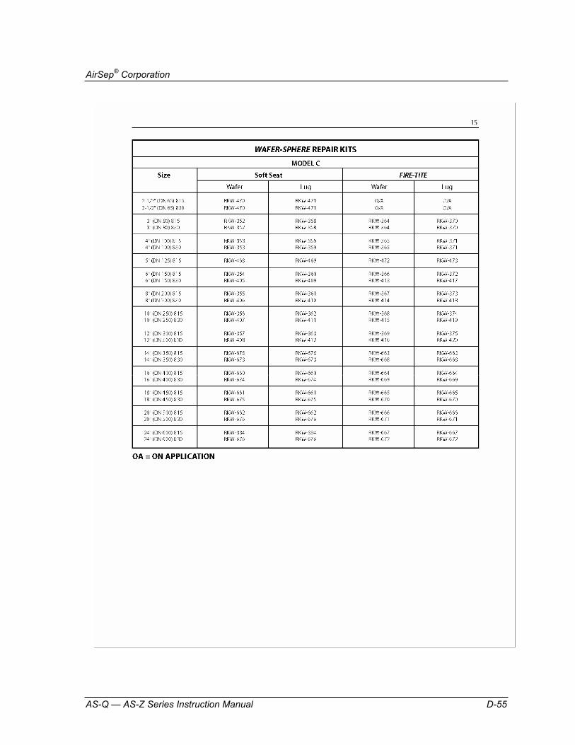
AirSep® Corporation
AS-Q — AS-Z Series Instruction Manual D-55

AirSep® Corporation
D-56 AS-Q — AS-Z Series Instruction Manual

AirSep® Corporation
AS-Q — AS-Z Series Instruction Manual D-57

AirSep® Corporation
D-58 AS-Q — AS-Z Series Instruction Manual

AirSep® Corporation
AS-Q — AS-Z Series Instruction Manual D-59

AirSep® Corporation
D-60 AS-Q — AS-Z Series Instruction Manual

AirSep® Corporation
AS-Q — AS-Z Series Instruction Manual D-61

AirSep® Corporation
D-62 AS-Q — AS-Z Series Instruction Manual

AirSep® Corporation
AS-Q — AS-Z Series Instruction Manual D-63

AirSep® Corporation
D-64 AS-Q — AS-Z Series Instruction Manual

AirSep® Corporation
AS-Q — AS-Z Series Instruction Manual D-65

AirSep® Corporation
D-66 AS-Q — AS-Z Series Instruction Manual

AirSep® Corporation
AS-Q — AS-Z Series Instruction Manual D-67

AirSep® Corporation
D-68 AS-Q — AS-Z Series Instruction Manual
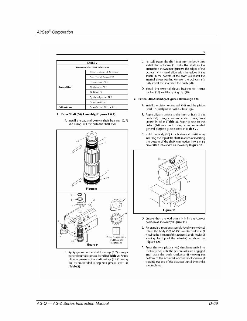
AirSep® Corporation
AS-Q — AS-Z Series Instruction Manual D-69
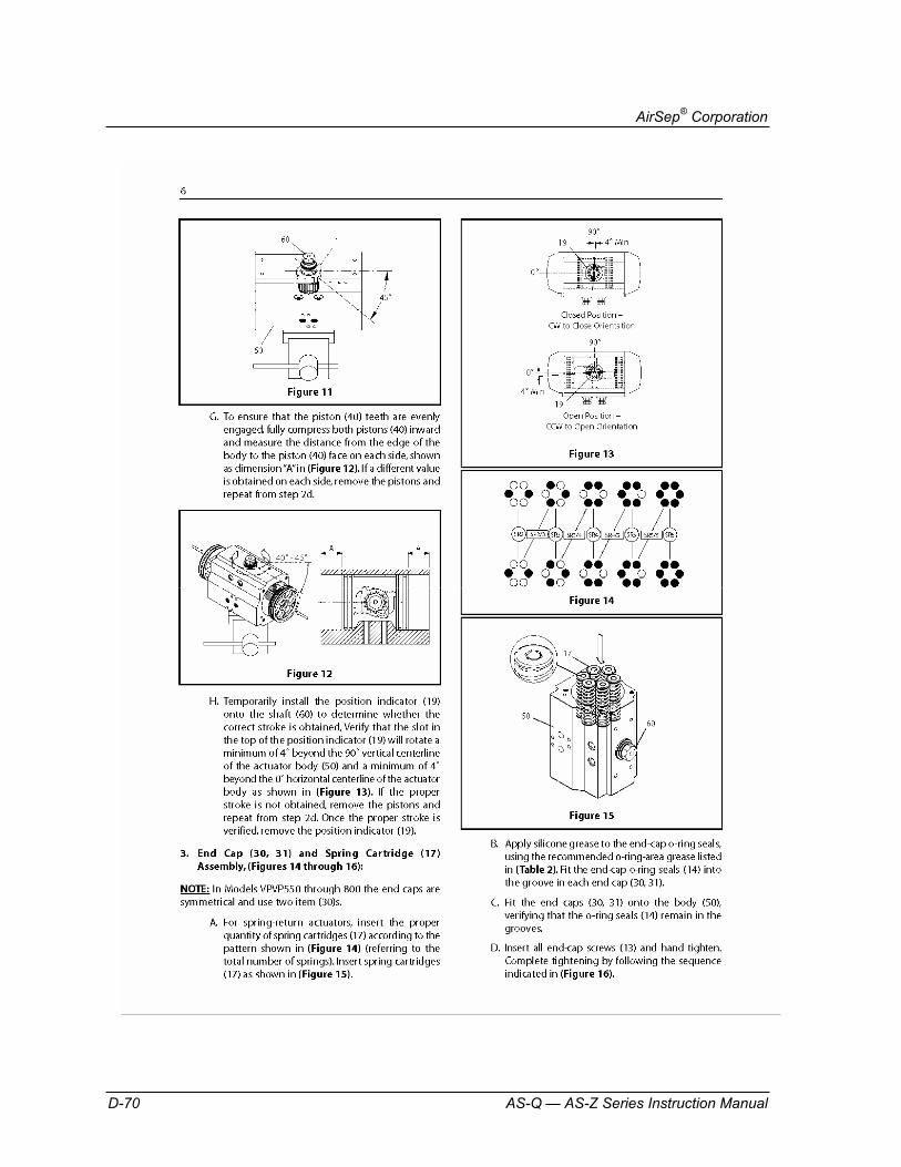
AirSep® Corporation
D-70 AS-Q — AS-Z Series Instruction Manual

AirSep® Corporation
AS-Q — AS-Z Series Instruction Manual D-71

AirSep® Corporation
D-72 AS-Q — AS-Z Series Instruction Manual
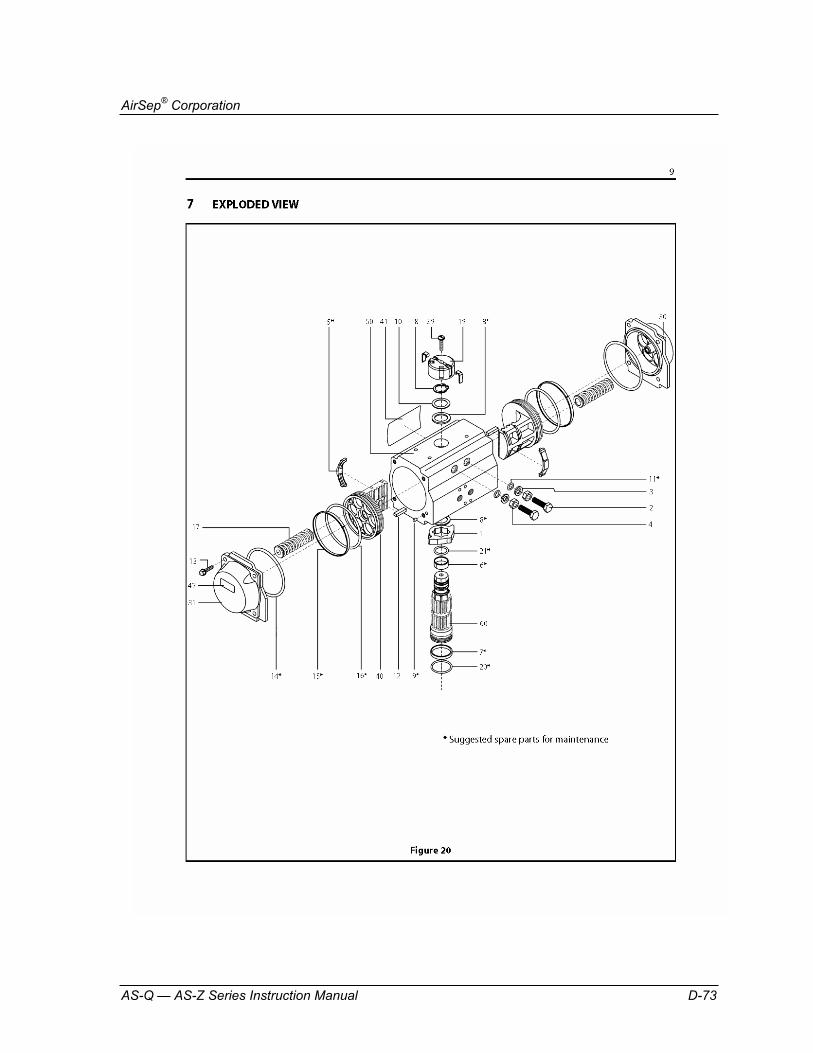
AirSep® Corporation
AS-Q — AS-Z Series Instruction Manual D-73

AirSep® Corporation
D-74 AS-Q — AS-Z Series Instruction Manual

AirSep® Corporation
AS-Q — AS-Z Series Instruction Manual D-75

AirSep® Corporation
D-76 AS-Q — AS-Z Series Instruction Manual

AirSep® Corporation
AS-Q — AS-Z Series Instruction Manual D-77

AirSep® Corporation
D-78 AS-Q — AS-Z Series Instruction Manual

AirSep® Corporation
AS-Q — AS-Z Series Instruction Manual D-79
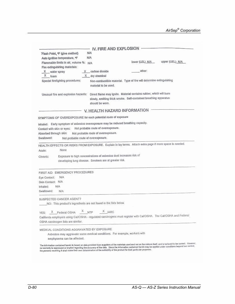
AirSep® Corporation
D-80 AS-Q — AS-Z Series Instruction Manual

AirSep® Corporation
AS-Q — AS-Z Series Instruction Manual D-81