Airplane Flight Simulation Training Devices
227
Standards Document Aeroplane Flight Simulation Training Devices SD-FSTD-A Civil Aviation Authority of Fiji Private Mail Bag NAP 0354 Nadi International Airport Fiji Copy Number: Electronic copy This manual is subject to the amendment service: □ Yes □ No Copy Holder: _________________________ Organisation: ________________________ Date of Effectiveness: 1 August 2018
Transcript of Airplane Flight Simulation Training Devices

Standards Document
Aeroplane Flight Simulation Training Devices
SD-FSTD-A
Civil Aviation Authority of Fiji Private Mail Bag NAP 0354 Nadi International Airport
Fiji Copy Number: Electronic copy
This manual is subject to the amendment service: □ Yes □ No
Copy Holder: _________________________
Organisation: ________________________
Date of Effectiveness: 1 August 2018

ISO 9001: 2015 CERTIFIED
Civil Aviation Authority of Fiji Standards Document – Airplane Flight Simulation Training Devices
Airplane Flight Simulation Training Devices
August 20, 2019
2
Airplane Flight Simulation Training Devices
Revision History
This section contains “Revision History” comments.
Version No.
Status Date Author’s Initials
Comments
1.0 First draft 1 August 2018
1.1 First amendment 20 August 2019 FT Amendment to Preface

ISO 9001: 2015 CERTIFIED
Civil Aviation Authority of Fiji Standards Document – Airplane Flight Simulation Training Devices
Airplane Flight Simulation Training Devices
August 20, 2019
3
Glossary of Terms
A. Flight Simulation Training Device (FSTD). A synthetic training device that is in compliance with the minimum requirements for FSTD qualification as described in this SD.
B. Flight Simulation Training Device User Approval (FSTD User Approval). The extent to which an FSTD of a specific Qualification Level may be used by persons, organizations or enterprises as approved by CAAF. It takes account of aeroplane to FSTD differences and the operating and training ability of the organization.
C. Flight Simulation Training Device Operator (FSTD operator).That person, organization or enterprise directly responsible to CAAF for requesting and maintaining the qualification of a particular FSTD.
D. Flight Simulation Training Device User (FSTD User).The person, organisation or enterprise requesting training, checking or testing credits through the use of a FSTD.
E. Flight Simulation Training Device Qualification (FSTD Qualification). The level of technical ability of an FSTD as defined in the compliance document.
F. Qualification Test Guide (QTG). A document designed to demonstrate that the performance and handling qualities of an FSTD agree within prescribed limits with those of the aeroplane and that all applicable regulatory requirements have been met. The QTG includes both the aeroplane and FSTD data used to support the validation.
G. CAAF Civil Aviation Authority of Fiji. The competent authority responsible for the determining the policy and compliance requirements for the operation of a FSTD.

Civil Aviation Authority of Fiji
ISO 9001 : 2015 CERTIFIED Standards Document: Aeroplane Flight Simulation Training Device
20 August 2019 4
PREFACE
General
Fiji’s National Aviation Law consists of a three tier regulatory system, comprising Acts, Regulations and
Standards Documents; the purpose of which is to ensure, where deemed appropriate, compliance and
conformance with ICAO Standards and Recommended Practices (SARPS).
The three tier regulatory system represents Fiji’s Primary Legislation System and Specific Operating
Regulations to meet Critical Elements CE1 and CE2 of ICAO’s Eight Critical Element of a safety oversight
system.
Standards Documents (SD) are issued by the Civil Aviation Authority of Fiji under the provision of Section
14 (3) (b) of the Civil Aviation Authority Act 1979 (CAP 174A)
Where appropriate, the SD also contains technical guidance (Critical Element CE5) on standards,
practices, and procedures that are acceptable to the Authority.
Notwithstanding the above, and where specifically indicated in this Standards Document that such a
provision is available, consideration may be given to other methods of compliance that may be presented
to the Authority provided they have compensating factors that can demonstrate a level of safety
equivalent to or better than those prescribed herein. Accordingly, the Authority will consider each case
based on its own merits holistically in the context of and relevancy of the alternative methods to the
individual applicant.
When new standards, practices, or procedures are determined to be acceptable, they will be added to
this document.
Purpose
This Standards Document – Airplane Flight Simulation Training Devices is intended for use by CAAF, applicants for, and holders of, an Air Operator Certificate and for their staff.
Change Notice
This Standards Document has been developed pursuant to the Authority’s obligation to provide oversight
on certified operators and their personnel, as well as the operator’s obligation to comply with standards
notified by the Authority and is the means by which such notification is given.

ISO 9001: 2015 CERTIFIED
Civil Aviation Authority of Fiji Standards Document – Airplane Flight Simulation Training Devices
Airplane Flight Simulation Training Devices
August 20, 2019
2
Foreword
The Civil Aviation Authority Fiji (CAAF) has developed the SD-FSTD-A as a basic harmonization of the ICAO Doc 9625 Edition 4, JAR-FSTD-A, EASA CS FSTD-A and the FAA 14 CFR Part 60, to describe the Qualification Criteria to be used for the Initial and Ongoing Qualification of FSTDs in Fiji.
Background
This Manual aligns Fiji’s requirements for aeroplane flight simulators with EASA CS FSTD-A augmented by ICAO Manual 9625 Issue 4 and the FAA 14 CFR Part 60, where acceptable with the following changes:
a) replacement of generic regulatory information by specific CAAF material,
b) Definitions and abbreviations of terms used in SD-FSTD-A are considered generally applicable as in the EASA CS-FSTD A. However, definitions and abbreviations of terms used in this document that are specific to a Subpart of SD-FSTD-A are normally given in the Subpart concerned or, exceptionally, in the associated compliance or interpretative material.
c) Reference to FSTDs prior to certain dates have been deleted.
d) Removal of “intentionally blank” pages.
e) Some reformatting for readability.
f) This document is to be used under the delegation of ANR 146.

ISO 9001: 2015 CERTIFIED
Civil Aviation Authority of Fiji Standards Document – Airplane Flight Simulation Training Devices
Airplane Flight Simulation Training Devices
August 20, 2019
3
Document Set
The document hierarchy consists of:
A. CAAF ANR 146;
B. CAAF SD-FSTD-A; and
C. Applicable Circulars (ACs).
The regulatory documents establish, for service providers, a comprehensive description of system requirements and the means of meeting them.
ANRs establish the regulatory framework (Regulations) within which all service providers must operate.
SD-FSTD-A comprises specifications (Standards) prescribed by CAAF.
Service providers must document internal actions (Rules) in their own operational manuals, to ensure the maintenance of and compliance with standards.
ACs (Applicable Circulars) are intended to provide recommendations and guidance to illustrate a means, but not necessarily the only means of complying with the SD. ACs may explain certain regulatory requirements by providing interpretive and explanatory materials. It is expected that service providers will document internal actions in their own operational manuals, to put into effect those, or similarly adequate, practices.
Differences between ICAO Standards and those in SD-FSTD-A
Notwithstanding the above, where there is a difference between a standard prescribed in ICAO documents and the SD, the SD standard shall prevail.
SD Documentation Change Management
Responsibility for the approval of the publication and amendment of the SD-FSTD-A resides with the Chief Executive, Civil Aviation Authority of the Fiji Islands.
Requests for any change to the content of the SD-FSTD-A may be initiated by:
a) Technical areas within CAAF;
b) FSTD training device operators;
c) FSTD training device users.
The need to change standards in the SD-FSTD-A may be generated by a number of causes. These may be to:
a) ensure safety;
b) ensure standardisation;
c) respond to changed CAAF standards;
d) respond to ICAO prescription;
e) Accommodate new initiatives or technologies.
Any amendment will be actioned in accordance with CAAF’s Notice of Proposed Amendment (NPA) procedures.

ISO 9001: 2015 CERTIFIED
Civil Aviation Authority of Fiji Standards Document – Airplane Flight Simulation Training Devices
Airplane Flight Simulation Training Devices
August 20, 2019
4
Related documents
Related national and international documents which form the basis of the criteria for FSTD Certification Standards:
IATA Flight Simulator Design and Performance Data Requirements 6th Edition 2000 or as
amended.
ICAO Annex 1 — Personnel Licensing
Annex 6 — Operation of Aircraft, Part I — International Commercial Air Transport — Aeroplanes
Doc 4444 — Procedures for Air Navigation Services — Air Traffic Management (PANS-ATM)
Doc 9868 — Procedures for Air Navigation Services — Training (PANS-TRG)
Doc 10011 — Manual on Aeroplane Upset Prevention and Recovery Training
ICAO Doc 9625 Manual of Criteria for the Qualification of Flight Simulators
Australia Civil Aviation Safety Regulations (CASR) Part 60, Synthetic Training Devices
Civil Aviation Order 45.0
FSD 1, Operational Standards and Requirements, Approved Flight Simulators
FSD 2, Operational Standards and Requirements, Approved Flight Training Devices
Canada TP9685, Aeroplane and Rotorcraft Simulator Manual
France Projet d’arrêté relatif à l’agrément des simulateurs de vol, 1988
Europe EASA CS-FSTD (A) and (H)
JAR-FSTD A, Aeroplane Flight Simulation Training Devices
Part-FCL TGL #7, Multi-crew Pilot Licence Training — Air Traffic Control Environment Simulation
United Kingdom C A P 453, Aeroplane Flight Simulators: Approval Requirements
United States FAA 14 CFR Part 60, Flight Simulation Training Device Initial and Continuing Qualification and Use
Advisory Circular 120-40B, Airplane Simulator Qualification
Advisory Circular 120-45A, Aeroplane Flight Training Device Qualification
Advisory Circular 120-63, Helicopter Simulator Qualification
FAA-S-8081-5F, Airline Transport Pilot and Type Rating Practical Test Standards for Aeroplanes
Additional related documents are:
ARINC Report 433 — Standard Measurements for Flight Simulation Quality
Report 436 — Guidelines for Electronic Qualification Test Guide
Report 439 — Guidance for Simulated Air Traffic Control Environments in FSTDs
IATA Flight Simulation Training Device Design and Performance Data Requirements Simulated Air and Ground Traffic Environment for Flight Training
RAeS Aeroplane Flight Simulator Evaluation Handbook, Volume I
Aeroplane Flight Simulator Evaluation Handbook, Volume II

ISO 9001: 2015 CERTIFIED
Civil Aviation Authority of Fiji Standards Document – Airplane Flight Simulation Training Devices
Airplane Flight Simulation Training Devices
August 20, 2019
5
Industry developed Aeroplane Upset Recovery Training Aid
Table of Contents
Subpart A – Administration General
Appicability 1.1
Privileges of Approval 1.2
Duration of Approval 1.3
Renewal of Approval 1.4
Requirements for the issue of a Flight Simulation Training Device Approval
1.5
Application for a Flight Simulation Training Device Approval 1.6
Variation, Suspension or Cancellation of Approval 1.7
Safety inspections and Audit 1.8
Subpart B - Operational Standards and Requirements
FSTD General Specifications 2.1
Training Credits for FSTDs 2.2
FSTD Operations Manual 2.3
FSTD Instructors 2.4
Subpart C - Evaluation, Accreditation and Fidelity Checks
Inspection for Evaluation, Accreditation and Fidelity 3.1
Section 1
Requirements for FSTDs 4.0
A001 Applicability 5.0
A005 Terminology 6.0
Aeroplane Flight Simulation Training Devices 7.0
A015 Application for FSTD Qualification 7.1
A020 Validity of FSTD Qualification 7.2
A025 Rules Governing FSTD Operations 7.3
A030 Requirements for FSTDs Qualified on or after March 2011 7.4
A040 Changes to Qualified FSTDs 7.5
A045 Interim FSTD Qualification 7.6
A050 Transferability of FSTD Qualification 7.7
Appendix 1 to CAAF FSTD A.030 FSTD Standards 7.8
Table of Flight Deck Layout and Structure 7.9

ISO 9001: 2015 CERTIFIED
Civil Aviation Authority of Fiji Standards Document – Airplane Flight Simulation Training Devices
Airplane Flight Simulation Training Devices
August 20, 2019
6
Section 2
Applicable Circulars 8.0
General 8.1
Presentation 8.2
AC A005 Terminology and Abbreviations 9.0
Terminology 9.1
Abbreviations 9.2
AC 1 to A015 FSTD Qualification - Application and Inspection 10.0
Letter of Application 10.1
Composition of Evaluation Team 10.1.2
AC 2 to A015 FSTD Evaluations 10.2
General 10.2.1
Initial Evaluations 10.2.2
Recurrent Evaluations 10.2.3
Functions and Subjective Tests 10.2.4
Typical Test Profile for a FSTD A 10.2.5
AC A020 Validity of FSTD Qualification 11.0
Prerequisites 11.1
Prerogative of CAAF 11.2
AC 1 to A025 Quality Systems 12.0
Introduction 12.1
General 12.1.1
Quality System 12.1.2
Quality Assurance Programme 12.1.3
Quality System Training 12.1.4
Standard Measurements for Flight Simulator Quality 12.1.5
AC 2 to A025 BITD Operators Quality System 12.2
Introduction 12.2.1
Quality Policy 12.2.2
Quality System 12.2.3
Quality Assurance Programme 12.2.4
Quality System Training 12.2.5
AC 3 to A025 Installations 12.3
Introduction 12.3.1

ISO 9001: 2015 CERTIFIED
Civil Aviation Authority of Fiji Standards Document – Airplane Flight Simulation Training Devices
Airplane Flight Simulation Training Devices
August 20, 2019
7
Expected Elements 12.3.2
AC A030 FSTDs Qualified on or after 1 March 2011 13.0
Introduction 13.1
Background 13.2
Levels of FSTD Qualification 13.3
Terminology 13.4
Testing for FSTD Qualification 13.5
Qualification Test Guide 13.6
Master Qualification Test Guide 13.7
Electronic Qualification Test Guide 13.8
Quality Management System and Configuration Management 13.9
Types of Evaluations 13.10
Conduct of Evaluations 13.11
Appendix 1 to AC 1 to CAAF FSTD A.03 Validation Test Tolerances 14.0
Flight Test Tolerances 14.1
Non Flight Test Tolerances 14.2
Section 3
FSTD Validation Tests 15.0
Introduction 15.1
Test Requirements 15.2
Parameters, Tolerances and Flight Conditions 15.3
Flight Condition Verification 15.4
Flight Condition Definitions 15.5
Table of Validation Tests 15.6
Information for Validation Tests 15.7
Engines 15.8
Control Dynamics 15.9
Ground Effect 15.10
Engineering Simulator Validation Data 15.11
Motion System 15.12
Visual System 15.13
Sound System 15.14
Section 4
Functions and Subjective Tests 16.0
Table of Functions and Subjective Tests 16.1
ISO 9001: 2015 CERTIFIED
Civil Aviation Authority of Fiji Standards Document – Airplane Flight Simulation Training Devices
Airplane Flight Simulation Training Devices
August 20, 2019
8
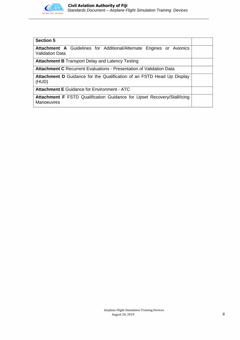
Section 5
Attachment A Guidelines for Additional/Alternate Engines or Avionics Validation Data
Attachment B Transport Delay and Latency Testing
Attachment C Recurrent Evaluations - Presentation of Validation Data
Attachment D Guidance for the Qualification of an FSTD Head Up Display (HUD)
Attachment E Guidance for Environment - ATC
Attachment F FSTD Qualification Guidance for Upset Recovery/Stall/Icing Manoeuvres

ISO 9001: 2015 CERTIFIED
Civil Aviation Authority of Fiji Standards Document – Airplane Flight Simulation Training Devices
Airplane Flight Simulation Training Devices
August 20, 2019
9
CHECK LIST OF PAGES
AEROPLANE FLIGHT SIMULATION TRAINING DEVICES
Initial issue dated 1 August 2018
The following pages of FSTD- A are current:
1 51 101
2 52 102
3 53 103
4 54 104
5 55 105
6 56 106
7 57 107
8 58 108
9 59 109
10 60 110
11 61 111
12 62 112
13 63 113
14 64 114
15 65 115
16 66 116
17 67 117
18 68 118
19 69 119
20 70 120
21 71 121
22 72 122
23 73 123
24 74 124
25 75 125
26 76 126
27 77 127
28 78 128
29 79 129
30 80 130
31 81 131
32 82 132
33 83 133
34 84 134
35 85 135
36 86 136
37 87 137
38 88 138
39 89 139
40 90 140
41 91 141
42 92 142
43 93 143
44 94 144
45 95 145
46 96 146
47 97 147
48 98 148
49 99 149
50 100 150
151 209

ISO 9001: 2015 CERTIFIED
Civil Aviation Authority of Fiji Standards Document – Airplane Flight Simulation Training Devices
Airplane Flight Simulation Training Devices
August 20, 2019
10
152 210
153 211
154 212
155 213
156 214
157 215
158 216
159 217
160 218
161 219
162 220
163 221
164 222
165 223
166 224
167 225
168
169
170
171
172
173
174
175
176
177
178
179
180
181
182
183
184
185
186
187
188
190
191
192
193
194
195
196
197
198
199
200
201
202
203
204
205
206
207
208

ISO 9001: 2015 CERTIFIED
Civil Aviation Authority of Fiji Standards Document – Airplane Flight Simulation Training Devices
Airplane Flight Simulation Training Devices
August 20, 2019
11
1. Subpart A — General
1.1 Applicability
This document prescribes standards governing the approval and operation of Flight Simulation Training Devices.
The purpose of the approval is a means by which the Authority can prescribe the following:-
a) The categorization of flight simulation training devices (FSTD)
b) The training credits available for each category
c) The standards and functional requirements for a FSTD to gain and maintain approval to a specific category
d) FSTD operations manual requirements
e) The requirements for FSTD instructors
f) The approval process for FSTD
1.2 Privileges Of Approval
The Flight Simulation Training Device Approval specifies the category and instrument flight credits that the holder is authorized to conduct.
Approved FSTDs may be used to accrue aeronautical experience for the purpose of:-
a) Instrument ground time
b) Instrument approach recency
c) Flight training and testing for the issue of pilot licences, aircrew ratings, instrument ratings and aircraft type ratings
d) Flight testing for the purpose of initial issue or renewing navigational aids endorsed on an instrument rating
1.3 Duration Of Approval
A standard Flight Simulation Training Device Approval will be granted or renewed for a period of 1 year.
Authority policy is that it will establish a surveillance programme, and subject to satisfactory performance, the organization can expect that the approval will be renewed. If performance is less than satisfactory, the approval may be renewed for a lesser period or not renewed.
The valid Approval must be displayed in a prominent position at the organization facility.

ISO 9001: 2015 CERTIFIED
Civil Aviation Authority of Fiji Standards Document – Airplane Flight Simulation Training Devices
Airplane Flight Simulation Training Devices
August 20, 2019
12
1.4 Renewal Of Approval
An application for the renewal of a Flight Simulation Training Device Approval shall be made to the Authority.
The Authority requires that an application for renewal be submitted before the application renewal date specified in the Approval or, if no such date is specified, not less than 30 days before the Approval expires. Notwithstanding this requirement, it is the responsibility of the applicant to ensure application is made in sufficient time to avoid approval expiration.
1.5 Requirements for the Issue of a Flight Simulation Training Device Approval
An applicant for a Flight Simulation Training Device Approval must satisfy the requirements of this Standards Document.
1.6 Application for a Flight Simulation Training Device Approval
A person or organization may apply to the Authority for the issue of a Flight Simulation Training Device Approval.
An application must be made on the appropriate form.
1.7 Variation, Suspension or Cancellation of an Approval
An organization operating an approved Flight Simulation Training Device must make an application to the Authority for any variation to the Approval.
If the holder of the Flight Simulation Training Device Approval does not comply with all the requirements of the Approval, the Approval may be suspended or revoked.
1.8 Safety Inspections and Audit
Each holder of a Flight Simulation Training Device Approval may be required by the Authority to undergo or carry out such inspections and audits of the holder’s facilities, documents and records as the Authority considers necessary in the interests of civil aviation safety and security in accordance with the Air Navigation Regulations.
The Authority may require the holder of a Flight Simulation Training Device Approval to provide such information as the Authority considers relevant to the inspection or audit.
The inspection and audit programme will normally be agreed between the Authority and the Approval holder at the time of issue of the Approval. This will allow for forward planning by both parties.
The Authority may also carry out spot checks or additional audits on an opportunity basis, or if the Authority has reasonable grounds to believe that the Approval holder is not in compliance with the requirements of this standards document.

ISO 9001: 2015 CERTIFIED
Civil Aviation Authority of Fiji Standards Document – Airplane Flight Simulation Training Devices
Airplane Flight Simulation Training Devices
August 20, 2019
13
2.0 Subpart B — Operational Standards and Requirements
2.1 General Specifications
A Flight Simulation Training Device may be granted approval in any of the following categories:
Full Flight Simulator (FFS); Level A, Level B, Level C, Level D.
A
The lowest level of FFS technical complexity.
An enclosed full-scale replica of the aeroplane cockpit/flight deck including simulation of all systems, instruments, navigational equipment, communications, and caution and warning systems.
An instructor’s station with seat should be provided. Seats for the flight crew members and two seats for inspectors/observers should also be provided.
Control forces and displacement characteristics should correspond to that those of the replicated aeroplane and they should respond in the same manner as the aeroplane under the same flight conditions.
The use of class-specific data tailored to the specific aeroplane type with fidelity sufficient to meet the objective tests, functions and subjective tests is allowed.
Generic ground effect and ground handling models are permitted.
Motion, visual and sound systems sufficient to support the training, testing and checking credits sought are required.
The visual system should provide at least 45 degrees horizontal and 30 degrees vertical field of view per pilot.
The response to control inputs should not be greater than 300 mcs more than that experienced on the aeroplane.
B
As for level A, plus:
Validation flight test data should be used as the basis for flight and performance and systems’ characteristics.
Additionally, ground handling and aerodynamics programming to include ground effect reaction and handling characteristics should be derived from validation flight test data.
C
The second highest level of FFS fidelity.
As for level B, plus:
A daylight/twilight/night visual system is required with a continuous, cross-cockpit, minimum collimated visual field of view providing each pilot with 180 degrees horizontal and 40 degrees vertical field of view.
A six-degrees-of-freedom motion system should be provided.
The sound simulation should include the sounds of precipitation and other significant aeroplane noises perceptible to the pilot and should be able to reproduce the sounds of a crash landing.
The response to control inputs should not be greater than 150 ms more than that experienced on the aeroplane.
Wind shear simulation should be provided.
An upset prevention and recovery-training (UPRT) instructor operating station (IOS) feedback mechanism should be available.
D The highest level of FFS fidelity.
As for level C, plus: Extended set of sound and motion buffet tests.
Flight Training Device (FTD); Level 1, Level 2.
Flight and Navigation Procedures Trainer (FNPT); Level 1, Level 2, MCC.
Basic Instrument Training Device (BITD)

ISO 9001: 2015 CERTIFIED
Civil Aviation Authority of Fiji Standards Document – Airplane Flight Simulation Training Devices
Airplane Flight Simulation Training Devices
August 20, 2019
14
2.2 Training Credits for Flight Simulation Training Device
For Training Credits to be available the FSTD must be operated in accordance with the following conditions:
An approved instructor is present at the instructor station for the duration of the flight;
The FSTD has been approved in the appropriate category and for the appropriate credit;
The limitations of the minimum equipment list are observed;
Training is conducted in accordance with the FSTD Operations Manual.
The following credits are available to approve:
BITDs:
(Reserved)
FNPTs:
1) Commercial Pilot Licence
a) 5 hours instrument time;
2) Initial Issue of Instrument rating
a) 20 hours instrument time (maximum);
b) 15 hours instrument cross country time;
c) DME or GPS Arrival.
3) Recency
a) 2 hours instrument time in 90 days;
b) Instrument approach recency requirements for ILS, LLZ, VOR, NDB, DME or GPS Arrival, RNAV (GNSS).
4) Renewal
a) ILS, LLZ, VOR, NDB, DME or GPS Arrival, RNAV (GNSS). At least one approach to be demonstrated in flight.
FTDs:
(Reserved)
FFS:
The level of accreditation of the simulator will determine the credits available;

ISO 9001: 2015 CERTIFIED
Civil Aviation Authority of Fiji Standards Document – Airplane Flight Simulation Training Devices
Airplane Flight Simulation Training Devices
August 20, 2019
15
2.3 Flight Simulation Training Device Operations Manual
The approved FSTD must be operated in accordance with its operations manual.
CAAF may only issue an approval if it is satisfied with the content of the operations manual. Any amendments to the operations manual require CAAF approval prior to being incorporated in the manual.
The operations manual must include:-
A copy of the Flight Simulation Training Device Approval;
A list of authorized instructors;
A minimum equipment list for the FSTD
A maintenance log for the reporting and clearing of defects;
A system to record periodic calibration and monitoring;
A section containing adequate operating procedures and instructions for pilots which must include:
a) A description of the FSTD;
b) A description of the FSTDs systems and capabilities;
c) Operating procedures and checks for normal operations;
d) Operating procedures and checks for simulated emergency operations;
e) Clearly marked instructions or procedures for any real emergencies or limitations.
A section containing adequate operating procedures and instructions for instructors which must include:
a) Operating procedures and checks for normal operations;
b) Instructions on the use of the instructor’s console;
c) Instructions for the use of the flight path display device;
d) Clearly marked instructions or procedures for any real emergencies or limitations.
The Flight Simulation Training Device Operations Manual must contain the training syllabi and sequences applicable to:-
The FSTD approved credits;
Pilot endorsement and approval;
Instructor endorsement and approval.
The description of the sequences required in each syllabus must be sufficiently detailed so that they could be flown without further explanation. The sequences must clearly indicate where simulated air traffic procedures are required.

ISO 9001: 2015 CERTIFIED
Civil Aviation Authority of Fiji Standards Document – Airplane Flight Simulation Training Devices
Airplane Flight Simulation Training Devices
August 20, 2019
16
2.4 Flight Simulation Training Device Examiners and Instructors
The Authority requires the Organisation to establish a Qualification Programme for initially assessing and maintaining the competence of those personnel conducting FSTD Training or checking. The FSTD instructor should have completed an Instructional Techniques course and the organization will determine the need for Refresher Training. The instructor will complete a simulator training programme consisting of a number of observation details, simulator instructor panel operations and attend a briefing by a nominated person covering required documentation and forms, and Regulatory awareness topics. Base and Instrument Rating renewal checks will be conducted only by approved Check Examiners.

ISO 9001: 2015 CERTIFIED
Civil Aviation Authority of Fiji Standards Document – Airplane Flight Simulation Training Devices
Airplane Flight Simulation Training Devices
August 20, 2019
17
3.0 Subpart C — Evaluation, Accreditation and Fidelity Checks
3.1 Inspection for Evaluation, Accreditation and Fidelity
A Flight Simulation Training Device must be inspected for evaluation, accreditation or fidelity by a CAAF Flying Operations Inspector.
Qualification is achieved by comparing the FSTD performance against the criteria specified in the Qualification Test Guide (QTG) for the qualification level sought.
The validation, functions and subjective tests required for the QTG enable the CAA to “spot check” the performance of the FSTD in order to confirm that it represents the aeroplane in some significant training and testing or checking areas. Without such spot-checking using the QTG, FSTD performance cannot be verified in the time normally available for the regulatory evaluation.
It should be clearly understood that the QTG does not provide for a rigorous examination of the quality of the simulation in all areas of flight and systems operation.
The full testing of the FSTD is intended to have been completed by the FSTD manufacturer and its operator prior to the FSTD being submitted for the regulatory evaluation and prior to the delivery of the results in the QTG.
This “in depth” testing is a fundamental part of the whole cycle of testing and is normally carried out using documented acceptance test procedures in which the test results are recorded.
These procedures will test the functionality and performance of many areas of the simulation that are not addressed in the QTG as well as such items as the instructor operating station.
Once the FSTD has been qualified, CAAF can approve what training tasks can be carried out. This determination should be based on the FSTD qualification, the availability of FSTDs, the experience of the FSTD user, the training programme in which the FSTD is to be used and the experience and qualifications of the pilots to be trained.
This latter process results in the approved use of an FSTD within an approved training programme.
The details of the inspection must be recorded in accordance with FSTD-A.
A copy of the completed inspection / check and those subsequently used in recurrent fidelity checks must be retained permanently with the FSTD.

ISO 9001: 2015 CERTIFIED
Civil Aviation Authority of Fiji Standards Document – Airplane Flight Simulation Training Devices
Airplane Flight Simulation Training Devices
August 20, 2019
18
Subpart C - Section 1
4.0 Requirements for Flight Simulation Training Devices
General
This section contains the minimum requirements for aeroplane Flight Simulation Training Devices.
Presentation
The requirements of FSTD- A are presented on loose pages, each page being identified by the date of issue and the Amendment number under which it is amended or reissued.
Sub-headings are in italic typeface.
Explanatory Notes not forming part of the requirements appear in smaller typeface.
New, amended and corrected text will be enclosed within heavy brackets until a subsequent Amendment is issued.
After each paragraph, the various changes and amendments, if any since the initial issue, are indicated together with their date of issue.
5.0 CAAF FSTD A.001 Applicability
FSTD-A as amended applies to a training device that is in compliance with the minimum requirements for FSTD qualification as described in this SD.
The FSTD-A will apply to all FSTD located and operated as Simulation Training Devices within the borders of the republic of Fiji by any local or foreign operator.
No Certificate of Qualification for a FSTD issued by an ICAO Contracting State or any other Civil Aviation Authority to a FSTD located within the borders of the Republic of Fiji, will be acceptable to the Civil Aviation Authority Fiji unless the FSTD has been granted a Qualification Level by CAAF under CAAF SD-FSTD-A.
The version of FSTD-A agreed by the Authority and used for the initial qualification of the device shall be applicable for future recurrent qualifications of the FSTD, unless re-categorised.
FSTD users are required to gain approval to use the FSTD as part of their approved training programmes.

ISO 9001: 2015 CERTIFIED
Civil Aviation Authority of Fiji Standards Document – Airplane Flight Simulation Training Devices
Airplane Flight Simulation Training Devices
August 20, 2019
19
6.0 CAAF FSTD A.005 Terminology
Because of the technical complexity of FSTD qualification, it is essential that standard terminology is used throughout. The following principal in terms and abbreviations shall be used in order to comply with CAAF SD -FSTD-A.
Further terms and abbreviations are contained in AC FSTD A.005.
A. Flight Simulation Training Device (FSTD). A synthetic training device that is in compliance with the minimum requirements for FSTD qualification as described in this SD.
B. Full Flight Simulator (FFS). A full size replica of a specific type or make, model and series aeroplane flight deck, including the assemblage of all equipment and computer programmes necessary to represent the aeroplane in ground and flight operations, a visual system providing an out of the flight deck view, and a force cueing standards for FFS Qualification.
C. Flight Training Device (FTD). A full size replica of a specific aeroplane type‘s instruments, equipment, panels and controls in an open flight deck area or an enclosed aeroplane flight deck, including the assemblage of equipment and computer software programmes necessary to represent the aeroplane in ground and flight conditions to the extent of the systems installed in the device. It does not require a force cueing motion or visual system. It is in compliance with the minimum standards for a specific FTD Level of Qualification.
D. Flight and Navigation Procedures Trainer (FNPT). A training device which represents the flight deck or cockpit environment including the assemblage of equipment and computer programmes necessary to represent an aeroplane or class of aeroplane in flight operations to the extent that the systems appear to function as in an aeroplane. It is incompliance with the minimum standards for a specific FNPT Level of Qualification.
E. Basic Instrument Training Device (BITD). A ground based training device which represents the student pilot‘s station of a class of aeroplanes. It may use screen based instrument panels and spring-loaded flight controls, providing a training platform for at least the procedural aspects of instrument flight.
F. Other Training Device (OTD). A training aid other than FFS, FTD, FNPT or BITD which provides for training where a complete flight deck environment is not necessary.
G. Flight Simulation Training Device User Approval (FSTD User Approval). The extent to which an FSTD of a specific Qualification Level may be used by persons, organizations or enterprises as approved by CAAF. It takes account of aeroplane to FSTD differences and the operating and training ability of the organization.
H. Flight Simulation Training Device Operator (FSTD operator).That person, organization or enterprise directly responsible to CAAF for requesting and maintaining the qualification of a particular FSTD.
I. Flight Simulation Training Device User (FSTD User). The person, organisation or enterprise requesting training, checking or testing credits through the use of a FSTD.
J. Flight Simulation Training Device Qualification (FSTD Qualification). The level of technical ability of an FSTD as defined in the compliance document.
K. Qualification Test Guide (QTG). A document designed to demonstrate that the performance and handling qualities of an FSTD agree within prescribed limits with those of the aeroplane and that all applicable regulatory requirements have been met. The QTG includes both the aeroplane and FSTD data used to support the validation.

ISO 9001: 2015 CERTIFIED
Civil Aviation Authority of Fiji Standards Document – Airplane Flight Simulation Training Devices
Airplane Flight Simulation Training Devices
August 20, 2019
20
7.0 Aeroplane Flight Simulation Training Devices
7.1 CAAF FSTD A.015 Application for FSTD Qualification
(See AC 1 A015)
(See AC 2 A015)
a) The FSTD operator requiring evaluation of a FFS, FTD or FNPT shall apply to the Authority giving 3 months’ notice. In exceptional cases this period may be reduced to one month at the discretion of the Authority.
b) An FSTD Qualification Certificate will be issued following satisfactory completion of an evaluation of the FSTD by the Authority.
c) For BITDs the manufacturer of a new BITD model which requires evaluation shall apply to the Authority giving 3 months’ notice. In exceptional cases this period may be reduced to one month at the discretion of the Authority.
d) A BITD Qualification Certificate will be issued for the BITD model to the manufacturer following satisfactory completion of an initial evaluation by the Authority. This qualification certificate is valid for any devices manufactured to this standard without the need for the device to be subjected to further technical evaluation. The BITD model must clearly be identified by a BITD model number.
e) The numbering of the BITD model must clearly define the hardware and software configuration of the qualified BITD model. A running serial number shall follow the BITD model identification number.
7.2 CAAF FSTD A.020 Validity of FSTD Qualification
(See AC A020)
(a) An FSTD qualification is valid for 12 months unless otherwise specified by the Authority.
(b) An FSTD qualification revalidation can take place at any time within 60 days prior to the expiry of the validity of the qualification document. The new period of validity shall continue from the expiry date of the previous qualification document.
(c) The Authority shall refuse, revoke, suspend or vary an FSTD qualification, if the provisions of CAAF- FSTD are not satisfied.
(d) The qualification of each BITD model serial number is valid for 36 months from the commencement of operation, unless reduced by the Authority. It is the operator‘s responsibility to apply for the revalidation of the qualifications.

ISO 9001: 2015 CERTIFIED
Civil Aviation Authority of Fiji Standards Document – Airplane Flight Simulation Training Devices
Airplane Flight Simulation Training Devices
August 20, 2019
21
7.3 CAAF FSTD A.025 Rules Governing FSTD Operators
(See AC 1 A025)
(See AC 2 A025)
(See AC 3 A025)
The FSTD operator shall demonstrate his capability to maintain the performance, functions and other characteristics specified for the FSTD Qualification Level as follows:
A. Quality System
(1) A Quality System shall be established and a Quality Manager designated to monitor compliance with, and the adequacy of, procedures required to ensure the maintenance of the Qualification Level of FSTDs. Compliance monitoring shall include a feedback system to the Accountable Manager to ensure corrective action as necessary.
(2) The Quality System shall include a Quality Assurance Programme that contains performance, functions and characteristics being conducted in accordance with all applicable requirements, standards and procedures.
(3) The Quality System and the Quality Manager shall be acceptable to the Authority.
(4) The Quality System shall be described in relevant documentation.
B. Updating. An update is a result of a change to the existing device where it retains its existing qualification level. A link shall be maintained between the operator‘s organization, the Authority and the relevant manufacturers to incorporate important modifications, especially:
(1) Aeroplane modifications that are essential for training and checking shall be introduced into all affected FSTDs whether or not enforced by an airworthiness directive.
(2) Modification of FSTDs, including motion and visual systems (where applicable):
a) When essential for training and checking, FSTD operators shall update their FSTDs (for example in the light of data revisions). Modifications of the FSTD hardware and software that affect handling, performance and systems operation or any major modifications of the motion or visual system shall be evaluated to determine the impact on the original qualification criteria.
b ) The Authority shall be advised in advance of any major changes to determine if the tests carried out by the FSTD operator are satisfactory. The change may be approved through a recurrent evaluation or a special evaluation if deemed necessary by CAAF.
c) If such a change to an existing device would imply that the performance of the device could no longer meet the requirements at the time of initial qualification, but that the result of the change would, in the opinion of the CAA, clearly mean an improvement to the performance and training capabilities of the device altogether, then the CAA may accept the proposed change as an update while allowing the device to retain its original qualification level.
d) BITD operators shall maintain a link between their own organization, the Authority and the BITD manufacturer to incorporate important modifications.

ISO 9001: 2015 CERTIFIED
Civil Aviation Authority of Fiji Standards Document – Airplane Flight Simulation Training Devices
Airplane Flight Simulation Training Devices
August 20, 2019
22
C. Installations. Ensure that the FSTD is housed in a suitable environment that supports safe and reliable operation.
(1) The FSTD operator shall ensure that the FSTD and its installation comply with the local regulations for health and safety. However, as a minimum all FSTD occupants and maintenance personnel shall be briefed on FSTD safety to ensure that they are aware of all safety equipment and procedures in the FSTD in case of emergency.
(2) The FSTD safety features such as emergency stops and emergency lighting shall be checked at least annually and recorded by the FSTD operator.
D. Additional Equipment. Where additional equipment has been added to the FSTD, even though not required for qualification, it will be assessed to ensure that it does not adversely affect the quality of training. Therefore any subsequent modification removal or unserviceability could affect the qualification of the device.
7.4 CAAF FSTD A.030 Requirements for FSTD qualified on or after 1 March 2011
(See Appendix 1 to FSTD A.030)
(See AC 1 CAAF FSTD A.030)
a) Any FSTD submitted for initial evaluation on or after 1 March 2011 will be evaluated against applicable CAAF SD-FSTD-A criteria for the Qualification Levels applied for. Recurrent evaluations of a FSTD will be based on the same version of CAAF SD-FSTD-A that was applicable for its initial evaluation. An upgrade will be based on the currently applicable version of CAAF SD-FSTD-A.
b) A FSTD shall be assessed in those areas that are essential to completing the flight crew member training and checking process as applicable.
c) The FSTD shall be subjected to:
a. (1) Validation tests and
b. (2) Functions & subjective tests.
d) Data shall be of a standard that satisfies the Authority before the FSTD can gain a Qualification Level, the operator will show proof of ownership, and or the right to use the Data submitted to CAAF.
e) The FSTD operator shall submit a QTG in a form and manner that is acceptable to the Authority.
f) The QTG will only be approved after completion of an initial or upgrade evaluation, and when all the discrepancies in the QTG have been addressed to the satisfaction of the Authority. After inclusion of the results of the tests witnessed by the Authority, the approved QTG becomes the Master QTG (MQTG), which is the basis for the FSTD qualification and subsequent recurrent FSTD evaluations. A copy of the MQTG shall be delivered by the Type I manufacturer together with any Type I model delivered to an Operator.
g) The FSTD operator shall:
(1) Run the complete set of tests contained within the MQTG progressively between each annual evaluation by the Authority. All results, whether in or out of tolerances shall be dated and retained in order to satisfy both the FSTD operator and the Authority that FSTD standards are being maintained; and

ISO 9001: 2015 CERTIFIED
Civil Aviation Authority of Fiji Standards Document – Airplane Flight Simulation Training Devices
Airplane Flight Simulation Training Devices
August 20, 2019
23
(2) Establish a Configuration Control System to ensure the continued integrity of the hardware and software of the qualified FSTD.
7.5 CAAF FSTD A.040 Changes to qualified FSTD
a) Requirement to notify major changes to a FSTD.
The operator of a qualified FSTD shall inform the Authority of proposed major changes such as:
(1) Aeroplane modifications, which could affect FSTD qualification.
(2) FSTD hardware and or software modifications that could affect the handling qualities, performances or system representations.
(3) Relocation of the FSTD; and
(4) Any deactivation of the FSTD
The Authority may complete a special evaluation following major changes or when a FSTD appears not to be performing at its initial Qualification Level.
b) Upgrade of a FSTD.
An upgrade is defined as the raising of the qualification level of a device, which can only be achieved by undergoing a special qualification according to the latest applicable regulations.
(1) If an upgrade is proposed the FSTD operator shall seek the advice of the Authority and give full details of the modifications. If the upgrade evaluation does not fall upon the anniversary of the original qualification date, a special evaluation is required to permit the FSTD to continue to qualify even at the previous Qualification Level.
(2) In the case of a FSTD upgrade, an FSTD operator shall run all validation tests for the requested Qualification Level. Results from previous evaluations shall not be used to validate FSTD performance for the current upgrade.
c) Relocation of a FSTD
In instances where a FSTD is moved to a new location within Fiji, CAAF shall be advised before the planned activity along with a schedule of related events.
1. Prior to returning the FSTD to service at the new location, the FSTD operator should agree with CAAF which of the validation and functional tests from the QTG should be performed to ensure that the FSTD performance meets its original qualification standard. A copy of the test documentation should be retained with the FSTD records for review by CAAF.
2. In instances where a FSTD is being imported into Fiji from another location CAAF shall be advised before the planned activity along with a schedule of related events, which will include an inspection of the FSTD by the CAAF and running a full set of validation tests before being dismantled to establish the status of the QTG‘s, and the FSTD.
3. Prior to returning the FSTD to service at the new location, in Fiji the FSTD operator shall perform all of the validation tests, and the functions and subjective tests to ensure that the FSTD meets its origin qualification standard. A copy of the test documents shall be retained together with the FSTD records for review by CAAF f or approval as the new MQTG for the FSTD.
4. An evaluation of the FSTD in accordance with its original JAR, FAA qualification criteria shall be at the discretion of CAAF.

ISO 9001: 2015 CERTIFIED
Civil Aviation Authority of Fiji Standards Document – Airplane Flight Simulation Training Devices
Airplane Flight Simulation Training Devices
August 20, 2019
24
d) Deactivation of a currently qualified FSTD
(3) If a FSTD operator plans to remove a FSTD from active status for prolonged periods, CAAF shall be notified and suitable controls established for the period during which the FSTD is inactive.
(4) The FSTD operator shall agree to a procedure with the CAAF to ensure that the FSTD can be restored to active status at its original Qualification Level.
7.6 CAAF FSTD A.045 Interim FSTD Qualification
(See AC A045)
a) In case of new aeroplane programmes, special arrangements shall be made to enable an interim Qualification Level to be achieved.
b) For Full Flight Simulators, an Interim Qualification Level will only be granted for Type IV, V and VI.
c) Requirements, details relating to the issue, and the period of validity of an interim Qualification Level will be decided by the Authority.
7.7 CAAF FSTD A.050 Transferability of FSTD Qualification
When there is a change of FSTD operator:
a) The new FSTD operator shall advise the Authority in advance in order to agree upon a plan of transfer of the FSTD.
b) At the discretion of the Authority, the FSTD shall be subject to an evaluation in accordance with its original CAAF qualification criteria.
c) Provided that the FSTD performs to its original standard, its original Qualification Level may be restored. Revised user approval(s) may also be required.

ISO 9001: 2015 CERTIFIED
Civil Aviation Authority of Fiji Standards Document – Airplane Flight Simulation Training Devices
Airplane Flight Simulation Training Devices
August 20, 2019
25
7.8 Appendix 1 to CAAF FSTD A.030 FSTD Standards
This appendix describes the minimum FSTD requirements for qualifying a device to an internationally agreed type, as defined in Subpart B, 2.0.
The Validation Tests and Functions and Subjective Tests listed in Subpart C section 3 and 4 should also be consulted when determining the requirements for qualification.
Certain requirements included in this appendix should be supported with a statement of compliance (SOC) and, in some designated cases, an objective test.
The SOC should describe how the requirement was met, such as gear modelling approach, coefficient of friction sources, etc. In the following tabular listing of FSTD criteria, requirements for SOCs are indicated in the comments column.
For FNPT use in Multi-Crew Co-operation (MCC) training the general technical requirement are expressed in the MCC column with additional systems, instrumentation and indicators as required for MCC training and operation.
For MCC (Multi Crew Co-operation) minimum technical requirements are as for Level II, with the following additions or amendments:
1 Turbo-jet or turbo-prop engines.
2 Performance reserves, in case of an engine failure, to be in accordance with CAAF-25. These may
be simulated by a reduction in the aeroplane gross mass.
3 Retractable landing gear.
4 Pressurisation system.
5 De-icing systems
6 Fire detection / suppression system
7 Dual controls
8 Autopilot with automatic approach mode
9 2 VHF transceivers including oxygen masks intercom system
10 2 VHF NAV receivers (VOR, ILS, DME)
11 1 ADF receiver
12 1 Marker receiver
13 1 transponder
The following indicators shall be located in the same positions on the instrument panels of both pilots:
1 Airspeed
2 Flight attitude with flight director
3 Altimeter
4 Flight director with ILS (HSI)
5 Vertical speed
6 ADF
7 VOR
8 Marker indication (as appropriate)
9 Stop watch (as appropriate)

ISO 9001: 2015 CERTIFIED
Civil Aviation Authority of Fiji Standards Document – Airplane Flight Simulation Training Devices
Airplane Flight Simulation Training Devices
August 20, 2019
26
7.9 REQUIREMENT — FLIGHT DECK LAYOUT AND STRUCTURE
FLIGHT SIMULATOR TRAINING DEVICE STANDARDS
1.1. General
FFS LEVEL
FTD
LEVEL
FNPT LEVEL
BITD
COMPLIANCE
A B C D 1 2 I II MCC
A.1 A fully enclosed flight deck
A.2 A cockpit / flight deck sufficiently enclosed to exclude distraction, which will replicate that of the aeroplane or class of aeroplane simulated.
A.3 Flight deck, a full- scale replica of the aeroplane simulated.
Equipment for operation of the cockpit windows shall be included in the FSTD, but the actual windows need to be operable.
The flight deck, for FSTD purposes, consists of all that space forward of a cross section of the fuselage at the most extreme aft setting of the pilots ‘seats. Additional required flight crewmember duty stations and those required flight crewmember duty stations and those required bulkheads aft of the pilot seats are also considered part of the flight deck and shall replicate the aeroplane.
Flight deck observer seats are not considered to be additional flight crewmember duty stations and may be omitted.
Bulkheads containing items such as switches, circuit breakers, supplementary radio panels, etc. to which the flight crew may require access during any event after pre-flight cockpit preparation is complete are considered essential and may not be omitted.
Bulkheads containing only items such as landing gear pin storage compartments, fire axes or extinguishers, spare light bulbs, aeroplane document pouches etc. are not considered essential and may be omitted. Such items, or reasonable facsimile, shall still be available in the FSTD but may be relocated to a suitable location as near as practical to the original position. Fire axes and any similar purpose instruments need only be represented in silhouette.
A.4 Direction of movement of controls and switches identical to that in the aeroplane.

ISO 9001: 2015 CERTIFIED
Civil Aviation Authority of Fiji Standards Document – Airplane Flight Simulation Training Devices
Airplane Flight Simulation Training Devices
August 20, 2019
27
FLIGHT SIMULATOR TRAINING DEVICE STANDARDS
1.1 General
FFS LEVEL
FTD LEVEL
FNPT LEVEL
BITD
COMPLIANCE
A B C D 1 2 I II MCC
A.5 A full size panel of replicated system(s) which will have actuation of controls and switches that replicate those of the aeroplane simulated.
The use of electronically displayed images with physical overlay incorporating operable switches, knobs, buttons replicating aeroplane instruments panels may be acceptable.
A.6 Cockpit / flight deck switches, instruments, equipment, panels, systems, primary and secondary flight controls sufficient for the training events to be accomplished shall be located in a spatially correct flight deck area and will operate as, and represent those in, that aeroplane or class of aeroplane.
For Multi-Crew co-operation (MCC) qualification, additional instrumentation and indicators may be required. See table at start of this appendix.
For BITDs, the switches’ and controls’ size and shape and their location in the cockpit shall be representative.
A.7 Crew member’s seats shall be provided with sufficient adjustment to allow the occupant to achieve the design eye reference position appropriate to the aeroplane or class of aeroplane and for the visual system to be installed to align with that eye position.
B.1 Circuit breakers that affect procedures and / or result in observable cockpit indications properly located and functionally accurate.

ISO 9001: 2015 CERTIFIED
Civil Aviation Authority of Fiji Standards Document – Airplane Flight Simulation Training Devices
Airplane Flight Simulation Training Devices
August 20, 2019
28
FLIGHT SIMULATOR TRAINING DEVICE STANDARDS
1.1 General
FFS LEVEL
FTD LEVEL
FNPT LEVEL
BITD
COMPLIANCE
A B C D 1 2 I II MCC
C.1 Flight dynamics model that accounts for various combinations of drag and thrust normally encountered in flight corresponding to actual flight conditions, including the effect of change in aeroplane attitude, sideslip, thrust, drag, altitude, temperature, gross weight, moments of inertia, centre of gravity location, and configuration.
For FTD Levels 1 and 2 aerodynamic modeling sufficient to permit accurate systems operation and indication is acceptable.
For FNPTs and BITDs class specific modeling is acceptable.
D.1 All relevant instrument indications involved in the simulation of the applicable aeroplane shall automatically respond to control movement by a flight crewmember or induced disturbance to the simulated aeroplane; e.g. turbulence or wind shear.
For FNPTs instrument indications sufficient for the training events to be accomplished. Reference AC No. 3 to CAAF- FSTD A.030.
For BITDs instrument indications sufficient for the training events to be accomplished. Reference AC No. 4 to CAAF-FSTD A.030.
D.2 Lighting environment for panels and instruments shall be sufficient for the operation being conducted.
For FTD Level 2 lighting environment shall be as per aeroplane.
D.3 Instrument indications respond appropriately to icing effects.
E.1 Communications, navigation, and caution and warning equipment corresponding to that installed in the applicant‘s aeroplane with operation within the tolerances prescribed for the applicable airborne equipment.
For FTD level 1 applies where the appropriate systems are replicated.
E.2 Navigation equipment corresponding to that of the replicated aeroplane or class of aeroplanes, with operation within the tolerances prescribed for the actual airborne equipment. This shall include communication equipment (interphone and air/ground communications systems).

ISO 9001: 2015 CERTIFIED
Civil Aviation Authority of Fiji Standards Document – Airplane Flight Simulation Training Devices
Airplane Flight Simulation Training Devices
August 20, 2019
29
FLIGHT SIMULATOR TRAINING DEVICE STANDARDS
1.1 General
FFS LEVEL
FTD LEVEL
FNPT LEVEL
BITD
COMPLIANCE
A B C D 1 2 I II MCC
E.3 Navigational data with the corresponding approach facilities. Navigation aids should be usable within range without restriction.
For FTD level 1 applies where navigation equipment is replicated.
For all FFSs and FTDs level 2 where used for area or airfield competence training or checking, navigation data should be updated within 28 days.
For FNPTs and BITDs, complete navigational data for at least 5 different Fijian airports with corresponding precision and non-precision approach procedures including current updating within a period of 3 months.
F.1 In addition to the flight crewmember duty stations, three suitable seats for the instructor, delegated examiner and Authority inspector. The Authority will consider options to this standard based on unique cockpit configurations. These seats shall provide adequate vision to the pilot‘s panel and forward windows. Observer seats need not represent those found in the aeroplane but in the case of FSTDs fitted with a motion system, the seats shall be adequately secured to the floor of the FSTD, fitted with positive restraint devices and be of sufficient integrity to safely restrain the occupant during any known or predicted motion system excursion.
For FTDs and FNPTs, suitable seating arrangements for the Instructor and Examiner or Authority‘s Inspector should be provided.
For BITDs, suitable viewing arrangements for the Instructor should be provided.

ISO 9001: 2015 CERTIFIED
Civil Aviation Authority of Fiji Standards Document – Airplane Flight Simulation Training Devices
Airplane Flight Simulation Training Devices
August 20, 2019
30
FLIGHT SIMULATOR TRAINING DEVICE STANDARDS
1.1 General
FFS LEVEL
FTD LEVEL
FNPT LEVEL
BITD
COMPLIANCE
A B C D 1 2 I II MCC
G.1
FSTD systems shall simulate applicable aeroplane system operation, both on the ground and in flight. Systems shall be operative to the extent that all normal, abnormal, and emergency operating procedures can be accomplished.
For FTD Level 1, applies where system is simulated. For FNPTs systems shall be operative to the extent that it shall be possible to perform all normal, abnormal and emergency operations as may be appropriate to the aeroplane or class of aeroplanes being simulated and as required for the training.
G.2
For aeroplanes equipped with a stick pusher system (e.g. longitudinal control feel system, or equivalent) control forces, displacement, and surface position of the aeroplane correspond to those of the aeroplane being simulated.
A statement of compliance (SOC) is required verifying that the stick pusher system has been modelled, programmed, and validated using the aeroplane manufacturers design data or other acceptable data source. The SOC must address, at a minimum, the stick pusher activation and cancellation logic as well as system dynamics, control displacement and forces as a result of the stick pusher activation. This requirement applies only to FSTDs that are to be qualified to conduct full stall training tasks. Test required.
H.1
Instructor controls shall enable the operator to control all required system variables and insert abnormal or emergency conditions into the aeroplane systems.
Where applicable and as required for training the following shall be available:
- Position and flight freeze
- A facility to enable the dynamic plotting of the flight path on approaches, commencing at the final approach fix, including the vertical profile
- Hard copy of map and approach plot

ISO 9001: 2015 CERTIFIED
Civil Aviation Authority of Fiji Standards Document – Airplane Flight Simulation Training Devices
Airplane Flight Simulation Training Devices
August 20, 2019
31
FLIGHT SIMULATOR TRAINING DEVICE STANDARDS
1.1 General
FFS LEVEL
FTD LEVEL
FNPT LEVEL
BITD
COMPLIANCE
A B C D 1 2 I II MCC
H.2 The FSTD must have a real-time feedback tool that provides the instructor/evaluator with visibility of whenever the FSTD training envelope or aeroplane operating limits have been exceeded.
Additionally, and optionally, a recording mechanism may be utilized.
This feedback tool must include the following: a) FSTD validation envelope: This must be in the form of
an alpha/beta envelope (or equivalent method) depicting the “confidence level” of the aerodynamic model. This “confidence level” depends on the degree of flight validation or on the source of predictive methods. There must be a minimum of flaps-up and flaps-down envelope available.
b) Flight control inputs: These must enable the instructor/evaluator to assess the piots flight control displacements and forces (including fly-by-wire, as appropriate).
c) Aeroplane operational limits: This must display the aeroplanes operational limits during the manoeuvre as applicable for the configuration of the aeroplane.
A SOC is required that defines the source data used to construct the FSTD validation envelope. Refer to AC 12 SD FSTD (A).300

ISO 9001: 2015 CERTIFIED
Civil Aviation Authority of Fiji Standards Document – Airplane Flight Simulation Training Devices
Airplane Flight Simulation Training Devices
August 20, 2019
32
FLIGHT SIMULATOR TRAINING DEVICE STANDARDS
1.1 General
FFS LEVEL
FTD LEVEL
FNPT LEVEL
BITD
COMPLIANCE
A B C D 1 2 I II MCC
H.3 Upset scenarios: When equipped with instructor operating station (IOS) selectable dynamic aeroplane upsets, the IOS is to provide guidance on the method used to drive the FSTD into an upset condition, including any malfunction or degradation of the FSTDs functionality required to initiate the upset. The unrealistic degradation of simulator functionality (such as degrading flight control effectiveness) to drive an aeroplane upset is generally not acceptable unless used purely as a tool for repositioning the FSTFD with the pilot out of the loop.
A SOC is required to confirm that each upset prevention and recovery feature programmed at the IOS and the associated training manoeuvre have been evaluated by a suitably qualified pilot. Refer AC SD FSTD (A) .300 (a) (1).

ISO 9001: 2015 CERTIFIED
Civil Aviation Authority of Fiji Standards Document – Airplane Flight Simulation Training Devices
Airplane Flight Simulation Training Devices
August 20, 2019
33
FLIGHT SIMULATOR TRAINING DEVICE STANDARDS
1.1 General
FFS LEVEL
FTD LEVEL
FNPT LEVEL
BITD
COMPLIANCE
A B C D 1 2 I II MCC
I.1 Control forces and control travel shall correspond to that of the replicated aeroplane. Control forces shall react in the same manner as in the aeroplane under the same flight conditions.
For FTD Level 2 Control forces and control travel should correspond to that of the replicated aeroplane with CT&M. It is not intended that the device should be flown manually other than for short periods when the autopilot is temporarily disengaged.
For FNPT Level 1 and BITDs, control forces and control travel shall broadly correspond to that of the replicated aeroplane or class of aeroplane. Control force changes due to an increase / decrease in aeroplane speed are not necessary.
In addition for FNPT Level II and MCC control forces and control travels shall respond in the same manner under the same flight conditions as in the aeroplane or class of aeroplane being simulated.

ISO 9001: 2015 CERTIFIED
Civil Aviation Authority of Fiji Standards Document – Airplane Flight Simulation Training Devices
Airplane Flight Simulation Training Devices
August 20, 2019
34
FLIGHT SIMULATOR TRAINING DEVICE STANDARDS
1.1 General
FFS LEVEL
FTD LEVEL
FNPT LEVEL
BITD
COMPLIANCE
A B C D 1 2 I II MCC
J.1 Ground handling and aerodynamic programming shall include:
(1) Ground effect. For example: round-out, flare, and touchdown. This requires data on lift, drag, pitching moment, trim, and power ground effect.
(2) Ground reaction – reaction of the aeroplane upon contact with the runway during landing to include strut deflections, tire friction, side forces, and other appropriate data, such as weight and speed, necessary to identify the flight condition and configuration.
(3) Ground handling characteristics – steering inputs to include crosswind, braking, thrust reversing, deceleration and turning radius.
Statement of Compliance required. Tests required.
For Level A FFS, generic ground handling to the extent that allows turns within the confines of the runway, adequate control on flare, touchdown and roll-out (including from a cross-wind landing) only is acceptable.
For FNPTs, a generic ground handling model need only be provided to enable representative flare and touchdown effects.

ISO 9001: 2015 CERTIFIED
Civil Aviation Authority of Fiji Standards Document – Airplane Flight Simulation Training Devices
Airplane Flight Simulation Training Devices
August 20, 2019
35
FLIGHT SIMULATOR TRAINING DEVICE STANDARDS
1.1 General
FFS LEVEL
FTD LEVEL
FNPT LEVEL
BITD
COMPLIANCE
A B C D 1 2 I II MCC
K.1
Windshear models shall provide training in the specific skills required for recognition of wind shear phenomena and execution of recovery maneuvers. Such models shall be representative of measured or accident derived winds, but may include simplifications which ensure repeatable encounters. For example, models may consist of independent variable winds in multiple simultaneous components. Wind models shall be available for the following critical phases of flight:
(1) Prior to take-off rotation
(2) At lift-off
(3) During initial climb
(4) Short final approach
Tests required.
Refer to AC No. 1 to CAAF-FSTD A.030, Para 2.3, g.
L.1
Instructor controls for environmental effects including wind speed and direction shall be provided.
For FTDs environment modeling sufficient to permit accurate systems operation and indication.

ISO 9001: 2015 CERTIFIED
Civil Aviation Authority of Fiji Standards Document – Airplane Flight Simulation Training Devices
Airplane Flight Simulation Training Devices
August 20, 2019
36
FLIGHT SIMULATOR TRAINING DEVICE STANDARDS
1.1 General
FFS LEVEL
FTD LEVEL
FNPT LEVEL
BITD
COMPLIANCE
A B C D 1 2 I II MCC
M.1 Stopping and directional control forces shall be representative for at least the following runway conditions based on aeroplane related data:
(1) Dry
(2) Wet
(3) Icy
(4) Patchy wet
(5) Patchy icy
(6) Wet on rubber residue in touchdown zone.
Statement of Compliance required.
Objective Tests required for (1), (2), (3), Subjective check for (4), (5), (6).
N.1 Brake and tire failure dynamics (including antiskid) and decreased brake efficiency due to brake temperatures shall be representative and based on aeroplane related data.
Statement of Compliance required.
Subjective test is required for decreased braking efficiency due to brake temperature, if applicable.
O.1 A means for quickly and effectively conducting daily testing of FSTD programming and hardware shall be available.
Statement of Compliance required.
P.1 Computer capacity, accuracy, resolution, and dynamic response shall be sufficient to fully support the overall fidelity, including its evaluation and testing.
Statement of Compliance required.

ISO 9001: 2015 CERTIFIED
Civil Aviation Authority of Fiji Standards Document – Airplane Flight Simulation Training Devices
Airplane Flight Simulation Training Devices
August 20, 2019
37
FLIGHT SIMULATOR TRAINING DEVICE STANDARDS
1.1 General
FFS LEVEL
FTD LEVEL
FNPT LEVEL
BITD
COMPLIANCE
A B C D 1 2 I II MCC
Q.1 Control feel dynamics shall replicate the aeroplane simulated.
Free response of the controls shall match that of the aeroplane within the tolerances specified. Initial and upgrade evaluations will include control free response (pitch, roll and yaw controller) measurements recorded at the controls. The measured responses shall correspond to those of the aeroplane in take-off, cruise, and landing configurations.
(1) For aeroplanes with irreversible control systems, measurements may be obtained on the ground if proper pitot static inputs are provided to represent conditions typical of those encountered in flight. Engineering validation or aeroplane manufacturer rationale will be submitted as justification to ground test or omit a configuration.
(2) For FSTDs requiring static and dynamic tests at the controls, special test fixtures will not be required during initial evaluation if the FSTD operator‘s MQTG shows both text fixture results and alternate test method results such as computer data plots, which were obtained concurrently. Repetition of the alternate method during initial evaluation may then satisfy this requirement.
Tests required.

ISO 9001: 2015 CERTIFIED
Civil Aviation Authority of Fiji Standards Document – Airplane Flight Simulation Training Devices
Airplane Flight Simulation Training Devices
August 20, 2019
38
FLIGHT SIMULATOR TRAINING DEVICE STANDARDS
1.1 General
FFS LEVEL
FTD LEVEL
FNPT LEVEL
BITD
COMPLIANCE
A B C D 1 2 I II MCC
R.1 One of the following two methods is acceptable as a means to prove compliance:
(1) Transport Delay: A transport delay test may be used to demonstrate that the FSTD system response does not exceed 150 milliseconds. This test shall measure all the delay encountered by a step signal migrating from the pilot‘s control through the control loading electronics and interfacing through all the simulation software modules in the correct order, using a handshaking protocol, finally through the normal output interfaces to the motion system, to the visual system and instrument displays.
(2) Latency: The visual system, flight deck instruments and initial motion system response shall respond to abrupt pitch, roll and yaw inputs from the pilot‘s position within 150 milliseconds of the time, but not before the time, when the aeroplane would respond under the same conditions.
Tests required.
For Level A & B FFSs, and applicable systems for FTDs, FNPTs and BITDs the maximum permissible delay is 300 milliseconds.

ISO 9001: 2015 CERTIFIED
Civil Aviation Authority of Fiji Standards Document – Airplane Flight Simulation Training Devices
Airplane Flight Simulation Training Devices
August 20, 2019
39
FLIGHT SIMULATOR TRAINING DEVICE STANDARDS
1.1 General
FFS LEVEL
FTD
LEVEL
FNPT LEVEL
BITD
COMPLIANCE
A B C D 1 2 I II MCC
S.1 Aerodynamic modeling includes, for aeroplanes issued an original type certificate after June 1980, low altitude level flight ground effect, Mach effect at high altitude, normal and reverse dynamic thrust effect on control surfaces, aero elastic representations, and representations of non-linearity‘s due to sideslip based on aeroplane flight test data provided by the manufacturer.
Statement of Compliance required, to include: Mach effect, aero elastic representations, ground effect, and non-linearity‘s due to sideslip. Separate tests for thrust effects. Refer to AC SD FSTD (A) .300 (a) (2).
S.2 The aerodynamic model has to incorporate data representing the aeroplanes characteristics covering and angle of attack and sideslip range to support the training tasks.
Statement of Compliance required. Refer to AC 9 SD FSTD (A) .300 (a) (3).
S.3 Applicable only for those FSTDs that are to be qualified for full stall training tasks.
The aerodynamic modelling has to support stall recovery training tasks in the following flight conditions: a) stall entry at wings level (1g) b) Stall entry into turning flight of at least 25° bank
angle (accelerated stall). c) Stall entry into a power on condition (required only
for propeller-driven aeroplanes) and, d) Aeroplane configurations of second segment
climb, high altitude cruise (near performance limited condition) and approach or landing.
A SOC is required which describes the aerodynamic modelling methods, validation, as well as a check of the stall characteristics of the FSTD. An additional SOC has also to include a verification that the FSTFD has been evaluated by a subject matter expert pilot acceptable to the competent authority. Refer to AC 10 SD FSTD (A) .300 (e) for clarification on the definition of a “subject matter expert pilot”. Refer to AC 9 SD FSTD (A) .300 (a) (4) for clarification on stall modelling. Refer to AC 1 SD FSTD (A) .200 for clarification of the “near performance limited condition”.

ISO 9001: 2015 CERTIFIED
Civil Aviation Authority of Fiji Standards Document – Airplane Flight Simulation Training Devices
Airplane Flight Simulation Training Devices
August 20, 2019
40
FLIGHT SIMULATOR TRAINING DEVICE STANDARDS
1.1 General
FFS LEVEL
FTD
LEVEL
FNPT LEVEL
BITD
COMPLIANCE
A B C D 1 2 I II MCC
T.1 Modeling that includes the effects of icing, where appropriate, on the airframe, aerodynamics and the engine (s). Icing effects simulation models are only required for those aeroplanes authorized for operations in icing conditions.
Icing models simulate the aerodynamic degradation of ice accretion on
the airplane lifting surfaces, including (if present on the simulated
aeroplane) loss of lift, decrease in stall angle of attack, change in
pitching moment, decrease in control effectiveness, and changes in
control forces in addition to any overall increase in drag. Aeroplane
systems (such as stall protection system and auto-flight system) must
respond properly to ice accretion, consistent with the simulated
aeroplane.
Aeroplane OEM data or other acceptable analytical methods must be
used to develop ice accretion models. Acceptable analytical methods
may include wind tunnel analysis and/or engineering analysis of the
aerodynamic effects of icing on the aeroplane lifting surfaces coupled
with tuning and supplemental subjective assessment by a subject matter
expert pilot knowledgeable of the effect of ice accretion on the handling
qualities of the simulated aeroplane.
A SOC is required describing the effects that provide training in the
specific skills for recognition of icing phenomena and execution of
recovery. The SOC must describe the source data and any analytical
methods used to develop ice accretion models, including a verification
that these effects have been tested.
Refer to AC 13 SD FSTD (A) .300.
T.2 Modeling that includes the effects of icing, where appropriate, on the airframe, aerodynamics and the engine (s). Icing effects simulation models are only required for those aeroplanes authorized for operations in icing conditions.
A SOC is required describing the effects that provide training in the
specific skills for recognition of icing phenomena and execution of
recovery.
U.1 Aerodynamic and ground relation modeling for the effects of reverse thrust on directional control shall be provided.
Statement of Compliance required.
(page 2-C-44)

ISO 9001: 2015 CERTIFIED
Civil Aviation Authority of Fiji Standards Document – Airplane Flight Simulation Training Devices
Airplane Flight Simulation Training Devices
August 20, 2019
41
FLIGHT SIMULATOR TRAINING DEVICE STANDARDS
1.1 General
FFS LEVEL
FTD LEVEL
FNPT LEVEL
BITD
COMPLIANCE
A B C D 1 2 I II MCC
V.1 Realistic aeroplane mass properties, including mass, centre of gravity and moments of inertia as a function of payload and fuel loading shall be implemented.
Statement of Compliance required at initial evaluation. SOC shall include a range of tabulated target values to enable a demonstration of the mass properties model to be conducted from the instructor‘s station.
W.1 Self-testing for FSTD hardware and programming to determine compliance with the FSTD performance tests shall be provided. Evidence of testing shall include FSTD number, date, time, conditions, tolerances, and the appropriate dependent variables portrayed in comparison with the aeroplane standard.
Statement of Compliance required. Tests required.
X.1
Timely and permanent update of hardware and programming subsequent to aeroplane modification sufficient for the Qualification Level sought.
Y.1
Daily pre-flight documentation either in the daily log or in a location easily accessible for review is required.

ISO 9001: 2015 CERTIFIED
Civil Aviation Authority of Fiji Standards Document – Airplane Flight Simulation Training Devices
Airplane Flight Simulation Training Devices
August 20, 2019
42
FLIGHT SIMULATOR TRAINING DEVICE STANDARDS
2. Motion System
FFS LEVEL
FTD LEVEL
FNPT LEVEL
BITD
COMPLIANCE
A B C D 1 2 I II MCC
A.1 Motion cues as perceived by the pilot shall be representative of the aeroplane, e.g. touchdown cues shall be a function of the simulated rate of descent.
For FSTDs where motion systems are not specifically required, but have been added, they will be assessed to ensure that they do not adversely affect the qualification of the FSTD. For level C or level D devices, special consideration is given to the motion system response during upset prevention and recovery maneuvers. Notwithstanding the limitations of simulator motion, the operator should place specific emphasis on tuning out objectionable motion system response, where possible.
B.1 A motion system shall:
(1) Provide sufficient cueing, which may be of a generic nature to accomplish the required tasks.
(2) Have a minimum of 3 degrees of freedom (pitch, roll & heave).
(3) Produce cues at least equivalent to those of a six-degrees-of-freedom synergistic platform motion system.
Statement of Compliance required.
Tests required.
C.1 A means of recording the motion response time as required.

ISO 9001: 2015 CERTIFIED
Civil Aviation Authority of Fiji Standards Document – Airplane Flight Simulation Training Devices
Airplane Flight Simulation Training Devices
August 20, 2019
43
FLIGHT SIMULATOR TRAINING DEVICE STANDARDS
2.Motion System
FFS LEVEL
FTD LEVEL
FNPT LEVEL
BITD
COMPLIANCE
A B C D 1 2 I II MCC
D.1 Motion effects programming shall include:
(1) Effects of runway rumble, oleo deflections, groundspeed, uneven runway, centerline lights and taxiway characteristics.
(2) Buffets on the ground due to spoiler / speed brake extension and thrust reversal.
(3) Bumps associated with the landing gear.
(4) Buffet during extension and retraction of landing gear.
(5) Buffet in the air due to flap and spoiler / speed brake extension.
(6) Approach to stall buffet and stall buffet (where applicable).
(7) Touchdown cues for main and nose gear.
(8) Nose wheel scuffing.
(9) Thrust effect with brakes set.
(See next page)
For FFSs: Effects may be of a generic nature sufficient to accomplish the required tasks. For level B, C and D FFSs: if there are known flight conditions where buffet is the first indication of the stall, or where no stall buffet occurs, this characteristic should be included in the model.

ISO 9001: 2015 CERTIFIED
Civil Aviation Authority of Fiji Standards Document – Airplane Flight Simulation Training Devices
Airplane Flight Simulation Training Devices
August 20, 2019
44
FLIGHT SIMULATOR TRAINING DEVICE STANDARDS
2.Motion System
FFS LEVEL
FTD LEVEL
FNPT LEVEL
BITD
COMPLIANCE
A B C D 1 2 I II MCC
D.1 (continued)
(10) Mach and manoeuvre buffet.
(11) Tyre failure dynamics.
(12) Engine malfunction and engine damage.
(13) Tail and pod strike.
E.1 Motion vibrations: Tests with recorded results that allow the comparison of relative amplitudes versus frequency are required.
Characteristic motion vibrations that result from operation of the aeroplane in so far as vibration marks an event or aeroplane state that can be sensed at the flight deck shall be present. The FSTD shall be programmed and instrumented in such a manner that the characteristic vibration modes can be measured and compared with aeroplane data.
Statement of Compliance required.
Tests required.

ISO 9001: 2015 CERTIFIED
Civil Aviation Authority of Fiji Standards Document – Airplane Flight Simulation Training Devices
Airplane Flight Simulation Training Devices
August 20, 2019
45
FLIGHT SIMULATOR TRAINING DEVICE STANDARDS
3. Visual System
FFS LEVEL
FTD LEVEL
FNPT LEVEL
BITD
COMPLIANCE
A B C D 1 2 I II MCC
A.1 The visual system shall meet all the standards enumerated as applicable to the level of qualification requested by the applicant.
For FTDs, FNPT 1s and BITDs, when visual systems have been added by the FSTD operator even though not attracting specific credits, they will be assessed to ensure that they do not adversely affect the qualification of the FSTD.
For FSTDs if the visual system is to be used for the training of maneuvering by visual reference (such as route and airfield competence) then the visual system should at least comply with that required for level A FFS.
B.1 Continuous minimum collimated visual field-of- view of 45 degrees horizontal and 30 degrees vertical field of view simultaneously for each pilot.
SOC is acceptable in place of this test.
B.2 Continuous, cross-cockpit, minimum collimated visual field of view providing each pilot with 180 degrees horizontal and 40 degrees vertical field of view. Application of tolerances require the field of view to be not less than a total of 176 measured degrees horizontal field of view (including not less than ±88 measured degrees either side of the centre of the design eye point) and not less than a total of 36 measured degrees vertical field of view from the pilot‘s and co-pilot‘s eye points.
Consideration shall be given to optimizing the vertical field of view for the respective aeroplane cut-off angle.
SOC is acceptable in place of this test.

ISO 9001: 2015 CERTIFIED
Civil Aviation Authority of Fiji Standards Document – Airplane Flight Simulation Training Devices
Airplane Flight Simulation Training Devices
August 20, 2019
46
FLIGHT SIMULATOR TRAINING DEVICE STANDARDS
3.Visual System
FFS LEVEL
FTD LEVEL
FNPT LEVEL
BITD
COMPLIANCE
A B C D 1 2 I II MCC
B.3 A visual system (night/dusk or day) capable of providing a field-of-view of a minimum of 45 degrees horizontally and 30 degrees vertically, unless restricted by the type of aeroplane, simultaneously for each pilot, including adjustable cloud base and visibility.
The visual system need not be collimated but shall be capable of meeting the standards laid down in Part 3 and 4 (Validation, Functions and Subjective Tests – See AC No. 1 to CAAF-FSTD A.030).
SOC is acceptable in place of this test.
C.1 A means of recording the visual response time for visual systems.
D.1 System Geometry. The system fitted shall be free from optical discontinuities and artifacts that create non-realistic cues.
Test required. A statement of Compliance is acceptable in place of this test.
E.1 Visual textural cues to assess sink rate and depth perception during take-off and landing shall be provided.
For Level A FFS visual cueing shall be sufficient to support changes in approach path by using runway perspective.
F.1 Horizon, and attitude shall correlate to the simulated attitude indicator.
Statement of Compliance required.
G.1 Occulting – A minimum of ten levels shall be available.
Occulting shall be demonstrated.
Statement of Compliance required.
H.1 Surface (Vernier) resolution shall occupy a visual angle of not greater than 2 arc minutes in the visual display used on a scene from the pilot‘s eyepoint.
Test and Statement of Compliance required containing calculations confirming resolution.

ISO 9001: 2015 CERTIFIED
Civil Aviation Authority of Fiji Standards Document – Airplane Flight Simulation Training Devices
Airplane Flight Simulation Training Devices
August 20, 2019
47
FLIGHT SIMULATOR TRAINING DEVICE STANDARDS
3.Visual System
FFS LEVEL
FTD LEVEL
FNPT LEVEL
BITD
COMPLIANCE
A B C D 1 2 I II MCC
I.1 Surface contrast ratio shall be demonstrated by a raster drawn test pattern showing a contrast ratio of not less than 5:1
Test and Statement of Compliance required.
J.1 Highlight brightness shall be demonstrated using a raster drawn test pattern. The highlight brightness shall not be less than 20cd/m² (6ft-lamberts)
Test and Statement of Compliance required. Use of calligraphic lights to enhance raster brightness is acceptable.
K.1 Light point size – not greater than 5 arc minutes.
Test and Statement of Compliance required. This is equivalent to a light point resolution of 2.5 arc minutes.
L.1 Light point contrast ratio – not less than 25:1
Test and Statement of compliance required.
L.2 Light point contrast ratio – not less than 10:1
Test and Statement of compliance required.
M.1 Daylight, twilight and night visual capability as applicable for level of qualification sought.
Statement of Compliance required for system capability.
System objective and scene content tests are required.
M. 2 The visual system shall be capable of meeting, as a minimum, the system brightness and contrast ratio criteria as applicable for level of qualification sought.

ISO 9001: 2015 CERTIFIED
Civil Aviation Authority of Fiji Standards Document – Airplane Flight Simulation Training Devices
Airplane Flight Simulation Training Devices
August 20, 2019
48
FLIGHT SIMULATOR TRAINING DEVICE STANDARDS
3.Visual System
FFS LEVEL FTD LEVEL
FNPT LEVEL BITD COMPLIANCE
A B C D 1 2 I II MCC
M.3 Total scene content shall be comparable in detail to that produced by 10 000 visible textured surfaces and (in day) 6000 visible lights or (in twilight or night) 15 000 visible lights, and sufficient system capacity to display 16 simultaneously moving objects.
M.4 The system, when used in training, shall provide in daylight, full colour presentations and sufficient surfaces with appropriate textural cues to conduct a visual approach, landing and airport movement (taxi). Surface shading effects shall be consistent with simulated (static) sun position.

ISO 9001: 2015 CERTIFIED
Civil Aviation Authority of Fiji Standards Document – Airplane Flight Simulation Training Devices
Airplane Flight Simulation Training Devices
August 20, 2019
49
FLIGHT SIMULATOR TRAINING DEVICE STANDARDS
3.Visual System
FFS LEVEL FTD LEVEL
FNPT LEVEL BITD COMPLIANCE
A B C D 1 2 I II MCC
M.5 The system, when used in training, shall provide at twilight, as a minimum, full colour presentations of reduced ambient intensity, sufficient surfaces with appropriate textural cues that include self-illuminated objects such as road networks, ramp lighting and airport signage, to conduct a visual approach, landing and airport movement (taxi). Scenes shall include a definable horizon and typical terrain characteristics such as fields, roads and bodies of water and surfaces illuminated by representative ownship lighting (e.g. landing lights). If provided, directional horizon lighting shall have correct orientation and be consistent with surface shading effects.
M.6 The system, when used in training, shall provide at night, as a minimum, all features applicable to the twilight scene, as defined above, with the exception of the need to portray reduced ambient intensity that removes ground cues that are not self-illuminating or illuminated by ownship lights (e.g. landing lights).

ISO 9001: 2015 CERTIFIED
Civil Aviation Authority of Fiji Standards Document – Airplane Flight Simulation Training Devices
Airplane Flight Simulation Training Devices
August 20, 2019
50
FLIGHT SIMULATOR TRAINING DEVICE STANDARDS
4. Sound System
FFS LEVEL FTD LEVEL
FNPT LEVEL BITD COMPLIANCE
A B C D 1 2 I II MCC
A.1 Significant flight deck sounds which result from pilot actions corresponding to those of the aeroplane or class of aeroplane.
For FNTPs Level 1 and BITDs engine sounds only need be available.
B.1 Sound of precipitation, rain removal equipment and other significant aeroplane noises perceptible to the pilot during normal and abnormal operations and the sound of a crash when the FSTD is landed in excess of limitations.
Statement of Compliance required. Sounds have to be directionally representative. For FSTDs that are to be qualified for full stall training tasks, sounds associated with stall buffet have to be replicated, if significant in the aeroplane.
C.1 Comparable amplitude and frequency of flight deck noises, including engine and airframe sounds. The sounds shall be coordinated with the required weather.
Tests required.
D.1 The volume control shall have an indication of sound level setting which meets all qualification requirements.

ISO 9001: 2015 CERTIFIED
Civil Aviation Authority of Fiji Standards Document – Airplane Flight Simulation Training Devices
Airplane Flight Simulation Training Devices
August 20, 2019
51
Subpart C - Section 2
8.0 Applicable Circulars
8.1 General
This Section contains the Applicable Circulars that have been accepted for providing an acceptable means of compliance and have been included in and incorporated in the CAAF SD-FSTD-A.
Where a particular CAAF-FSTD paragraph does not have an Applicable Circular (AC), it is considered that no supplementary material is required.
8.2 Presentation
The AC, is presented in full-page width on loose pages, each page being identified by the date of issue and the amendment number under which it is amended or reissued.
The AC‘s contained in the CAAF SD-FSTD-A are issued as the original and as such have no amendment date.
A numbering system has been used in which the Applicable Circular (AC) uses the same number as the CAAF SD-FSTD-A paragraph to which it refers.
The number is introduced by the letters AC to distinguish the material from the FSTD itself.
The acronym AC also indicates the nature of the material and for this purpose the type of material is defined as follows:
Applicable Circulars (AC) illustrate a means, or several alternative means, but not necessarily the only possible means by which a requirement can be met. It should however be noted that where a new AC is developed, any such AC (which may be additional to an existing AC) will be amended into the document. Such AC will be designated as (acceptable means of compliance).
An AC as interpretative / explanatory material may contain material that helps to illustrate the meaning of a requirement. Such AC will be designated by (interpretative / explanatory material).
New AC material may, in the first place, be made available rapidly by being published as a Technical Guidance Leaflet (TGL) FSTD TGLs.
Note: Any person who considers that there may be alternative AC to those published should submit details to the Senior Manager, Aviation Personnel Standards, CAAF, for alternatives to be properly considered by CAAF. Possible alternative AC may not be used until published by CAAF as an AC.
Explanatory Notes not forming part of the AC text appear in a smaller typeface.
New, amended or corrected text is enclosed within heavy brackets.
After each AC, the various changes and amendments, when any since the initial issue, will be indicated together with their date of issue.
9.0 AC to CAAF FSTD A.005
9.1 Terminology
In addition to the principal terms defined in the requirement itself, additional terms used in context of the CAAF SD-FSTD-A have the following meanings:

ISO 9001: 2015 CERTIFIED
Civil Aviation Authority of Fiji Standards Document – Airplane Flight Simulation Training Devices
Airplane Flight Simulation Training Devices
August 20, 2019
52
Acceptable Change. A change to configuration, software etc. which qualifies as a potential candidate for alternative approach to validation.
Aircraft Performance Data. Performance data published by the aircraft manufacturer in documents such as the Aeroplane or Flight Manual, Operations Manual, Performance Engineering Manual, or equivalent.
Additional engines/Avionics. An FSTD which has simulation of more than one engine/avionics fit.
Airspeed. Calibrated airspeed unless otherwise specified (knots).
Airport Clutter. Ground – based entities added to a visual airport scene to create a sense of activity. Airport clutter may include both static and dynamic models such as gate infrastructure, baggage carts, ground personnel, ground service vehicles and aircraft parked or undertaking ground movements.
Altitude. Pressure altitude (metres or feet) unless specified otherwise.
Approved Data. Aeroplane data collected by application of good engineering practice and accepted for use by the CAA. The preferred data sources are the aeroplane manufacturers and/or original equipment manufacturers (OEM), however data supplied by other qualified sources may be considered.
Audited Engineering Simulation. An aircraft manufacturer‘s engineering simulation which has undergone a review by the appropriate regulatory Authorities and been found to be an acceptable source of supplemental validation data.
Automatic Testing. Flight Synthetic Training Device (FSTD) testing wherein all stimuli are under computer control.
Bank. Bank / Roll angle (degrees).
Baseline. A fully flight-test validated production aircraft simulation. May represent a new aircraft type or a major derivative.
Breakout. The force required at the pilot‘s primary controls to achieve initial movement of the control position.
Closed Loop Testing. A test method for which the input stimuli are generated by controllers which drive the FSTD to follow a pre-defined target response.
Computer Controlled Aircraft (CCA). An aircraft where the pilot inputs to the control surfaces are transferred and augmented via computers.
Control Sweep. A movement of the appropriate pilot‘s control from neutral to an extreme limit in one direction (forward, aft, right, or left), a continuous movement back through neutral to the opposite extreme position, and then a return to the neutral position.
Convertible FSTD. An FSTD in which hardware and software can be changed to that the FSTD becomes a replica of a different model or variant, usually of the same type aircraft. The same FSTD platform, cockpit shell, motion system, visual system, computers and necessary peripheral equipment can thus be used in more than one simulation.
Correct Trend and Magnitude (CT&M). A tolerance representing the appropriate general direction of movement of the aeroplane, or part thereof, with appropriate corresponding scale of forces, rates, accelerations etc.
Critical Engine Parameter. The engine parameter which is the most appropriate measure of propulsive force.

ISO 9001: 2015 CERTIFIED
Civil Aviation Authority of Fiji Standards Document – Airplane Flight Simulation Training Devices
Airplane Flight Simulation Training Devices
August 20, 2019
53
Damping (Critical). That minimum damping of a second order system such that no overshoot occurs in reaching a steady state value after being displaced from a position of equilibrium and released. This corresponds to a relative Damping ratio of 1:0.
Damping (Over-Damped). That damping of a second order system such that it has more damping than is required for Critical Damping, as described above. This corresponds to a relative damping ratio of more than 1:0.
Damping (Under-Damped). That Damping of a second order system such that a displacement from the equilibrium position and free release results in one or more overshoots or oscillations before reaching a steady state value. This corresponds to a relative Damping ratio of less than 1:0.
Daylight Visual. A visual system capable of meeting, as a minimum, system brightness, contrast ratio requirements and performance criteria appropriate for the level of qualification sought. The system, when used in training, should provide full colour presentations and sufficient surfaces with appropriate textural cues to successfully conduct a visual approach, landing and airport movement (taxi).
Deadband. The amount of movement of the input for a system for which there is no reaction in the output or state of the system observed.
Distance. Distance in Nautical Miles unless specified otherwise.
Driven. A state where the input stimulus or variable is driven or deposited by automatic means, generally a computer input. The input stimulus or variable may not necessarily be an exact match to the flight test comparison data – but simply driven to certain predetermined values.
Engineering Simulator Validation Data. Validation data generated by an engineering simulation or engineering simulator, that is acceptable to CAAF.
FSTD Approval. The extent to which an FSTD of a specified Qualification Level may be used by and operator or training organization as agreed by CAAF. It takes account of differences between aeroplanes and FSTDs and the operating and training ability of the organization.
FSTD Data. The various types of data used by the FSTD manufacturer and the applicant to design, manufacture, and test the FSTD.
FSTD Evaluation. A detailed appraisal of an FSTD by CAAF to ascertain whether or not the criteria required for a specified Qualification Level are met.
FSTD Operator. That person, organization or enterprise directly responsible to the CAA for requesting and maintaining the qualification of a particular FSTD.
FSTD Qualification Level. The level of technical capability of a FSTD.
Flight Test Data. Actual aeroplane data obtained by the aeroplane manufacturer (or other approved supplier of data) during an aircraft flight test programme.
Free Response. The response of the aeroplane after completion of a control input or disturbance.
Frozen / Locked. A test condition where a variable is held constant over time.
Fuel used. Mass of fuel used (kilos or pounds).
Full Sweep. See definition for “Control sweep”.
Functional Performance. An operation or performance that can be verified by objective data or other suitable reference material that may not necessarily be flight test data.

ISO 9001: 2015 CERTIFIED
Civil Aviation Authority of Fiji Standards Document – Airplane Flight Simulation Training Devices
Airplane Flight Simulation Training Devices
August 20, 2019
54
Functions Test. A quantitative and/or qualitative assessment of the operation and performance of an FSTD by a suitably qualified evaluator. The test should include verification of correct operation of controls, instruments, and systems of the simulated aeroplane under normal and non-normal conditions.
Functional performance. An operation or performance that can be verified by objective data or other suitable reference material which may not necessarily be Flight Test Data.
Ground Effect. A change in aerodynamic characteristics due to modification of the air flow past the aeroplane caused by the proximity to the ground.
Ground Reaction. Forces acting on the aeroplane due to contact with the ground. These forces include the effects of strut deflections, tyre friction, side forces, structural contact and other appropriate aspects. These forces change appropriately, for example, with weight and speed.
Hands-off. A test manoeuvre conducted or completed without pilot control inputs.
Hands-on. A test manoeuvre conducted or completed with pilot control inputs.
Heavy. Operational mass at or near maximum for the specified flight condition.
Height. Height above ground – AGL (meters or feet).
Highlight Brightness. The maximum displayed brightness.
Icing Accountability. Refers to changes from normal (as applicable to the individual aeroplane design) in take-off, climb (en-route, approach, landing) or landing operating procedures, or performance data (with reference to the Aeroplane Flight Manual) for flight in icing conditions or with ice accumulation on unprotected surfaces.
Integrated Testing. Testing of the FSTD such that all aeroplane system models are active and contribute appropriately to the results. None of the aeroplane system models should be substituted with models or other algorithms intended for testing only. This testing may be accomplished by using controller displacements as the input. These controllers should represent the displacement of the pilot‘s controls and these controls should have been calibrated.
Irreversible Control System. A control system in which movement of the control surface will not back-drive the pilot‘s control on the flight deck.
Latency. The additional time, beyond that of the basic perceivable response time of the aeroplane, due to the response of the FSTD.
Light. Operational mass at or near minimum for the specified flight condition.
Manual Testing. FSTD testing wherein the pilot conducts the test without computer inputs except for initial setup. All modules of the simulation should be active.
Master Qualification Test Guide (MQTG). CAAF approved test guide that incorporates the results of tests acceptable to the authorities at the initial qualification. The MQTG, as amended, serves as the reference for future evaluations. It may have to be re-established if any approved changes occur to the device, but should still be compliant with the approved data.
Medium. Normal operational mass for flight segment.
Night Visual. A visual system capable of producing, as a minimum, all features applicable to the twilight scene, (see “twilight,(dusk/dawn) visual”), with the exception of the need to portray reduced ambient intensity therefore lacking

ISO 9001: 2015 CERTIFIED
Civil Aviation Authority of Fiji Standards Document – Airplane Flight Simulation Training Devices
Airplane Flight Simulation Training Devices
August 20, 2019
55
ground cues that are not self-illuminating or illuminated by own ship lights (e.g. landing lights).
Nominal. Normal operational mass, configuration, speed etc. for the flight segment specified.
Non-normal Control. A state where one or more of the intended control, augmentation or protection functions are not fully available. Used in reference to computer-controlled aeroplanes. (Note: Specific terms such as Alternate, Direct, Secondary or backup, etc. may be used to define an actual level of degradation used in reference to computer-controlled aeroplanes).
Normal Control. A state where the intended control, augmentation and protection functions are fully available. Used in reference to computer-controlled aeroplanes.
Objective Test (Objective Testing). A quantities assessment based on comparison to data.
Other traffic. Entities other than the ownship in the simulated environment. This traffic will include other aircraft, both airborne and on the ground, and may also include ground vehicles as part of an airport scene.
Protection Functions. Systems functions designed to protect an aeroplane from exceeding its flight and manoeuvre limitations.
Qualification Test Guide (QTG). The primary reference document used for the evaluation of an FSTD. It contains test results, statements of compliance (SOC) and other prescribed information to enable the evaluator to assess whether the FSTD meets the test criteria described in this manual.
Reversible Control System. A control system in which movement of the control surface will back-drive the pilot‘s control on the flight deck.
Sideslip. Sideslip Angle (degrees).
Simulated ATC environment. The simulation of other traffic entities within an airspace or ground environment, along with the associated ATC radio and data communications to other traffic and the ownship within this wider context.
Snapshot. Presentation of one or more variables at a given instant of time.
Statement of Compliance (SOC). A declaration that specific requirements have been met.
Step Input. An abrupt input held at a constant value.
Subjective Test. A qualitative assessment based on established standards as interpreted by a suitably qualified person.
Throttle Lever Angle (TLA). The angle of the pilot‘s primary engine control lever(s) on the flight deck.
Time History. A presentation of the change of a variable with respect to time.
Transport Delay. The FSTD system processing time required for an input signal from a pilot primary flight control until motion system, visual system, and instrument response. It is a measure of the time from the flight control input through the hardware/software interface, through each of the host computer modules and back through the software/hardware interface to the motion system, flight instrument and visual system. Each of these three processing times excludes the aeroplane dynamic response and represents the transport delay for that particular system. It is the overall time delay incurred from signal input until

ISO 9001: 2015 CERTIFIED
Civil Aviation Authority of Fiji Standards Document – Airplane Flight Simulation Training Devices
Airplane Flight Simulation Training Devices
August 20, 2019
56
output response and is independent of the characteristic delay of the aeroplane being simulated.
Twilight (Dusk / Dawn) Visual. A visual system capable of meeting, as a minimum, full colour presentations of reduced ambient intensity and sufficient surfaces with appropriate textural cues that include self-illuminated objects such as road networks, ramp lighting and airport signage.
Update. The improvement or enhancement of an FSTD where it retains its existing qualification type.
Upgrade. The improvement or enhancement of an FSTD for the purpose of achieving a higher qualification type.
Validation Data. Data used to prove that the FSTD performance corresponds to that of the aeroplane.
Validation data roadmap (VDR). A document from the aeroplane validation data supplier that should clearly identify (in matrix format) the best possible sources of data for all required qualification tests in the QTG. It should also provide validity with respect to engine type and thrust rating and the revision levels of all avionics that affect aeroplane handling qualities and performance.
Validation Flight Test Data. Performance, stability and control, and other necessary test parameters electrically or electronically recorded in an aeroplane using a calibrated data acquisition system of sufficient resolution and verified as accurate to establish a reference set of relevant parameters to which like FSTD parameters can be compared.
Validation Test. A test by which FSTD parameters can be compared with the relevant validation data.
Visual Ground Segment. The visible distance on the ground, between the lower cut-off of the aeroplane cockpit and the furthest visible point, as limited by the prevailing visibility.

ISO 9001: 2015 CERTIFIED
Civil Aviation Authority of Fiji Standards Document – Airplane Flight Simulation Training Devices
Airplane Flight Simulation Training Devices
August 20, 2019
57
9.2 Abbreviations
The abbreviations and units used in this Standards Document have the following meaning:
A/C Aircraft
Ad Total initial displacement of pilot controller (initial displacement to
final resting amplitude)
An Sequential amplitude of overshoot after initial X-axis crossing
(e.g. A1 = first overshoot)
ACARS Aircraft Communication Addressing and Reporting System
ADS-B Automatic Dependent Surveillance - Broadcast
ADS-C Automatic Dependent Surveillance - Contract
ADS-R Automatic Dependant Surveillance - Rebroadcast
AFM Aeroplane Flight Manual
AGL above Ground Level (m or ft.)
AOA Angle of Attack (degrees)
AOC Aeronautical Operational Communications
APCH Approach
APU Auxiliary Power Unit
APV Approach Procedures with Vertical guidance
ASOS Automated Surface Observation System
ATC Air Traffic Control
ATIS Automatic Terminal Information Service
ATN Aeronautical Telecommunication Network
ATO Approved Training Organization
ATPL Airline Transport Pilot Licence (Certificate or Type Rating)
ATS Air Traffic Services
AWOS Automated Weather Observation System
Baro Barometric
BITE Built-in Test Equipment
BOM Basic Operating Mass
CAA Civil Aviation Authority
CAP Civil Aviation Publication
CAT I/II/III Precision approach and landing operations category
CCA Computer-Controlled Aeroplane
CCD Charge-Coupled Device
CDFA Continuous Descent Final Approach
cd/m2 Candela/metre2 (3.4263 candela/m2 = 1 ft.-lambert)
CFIT Controlled Flight into Terrain

ISO 9001: 2015 CERTIFIED
Civil Aviation Authority of Fiji Standards Document – Airplane Flight Simulation Training Devices
Airplane Flight Simulation Training Devices
August 20, 2019
58
CFR Code of Federal Regulations
cg Centre of gravity
cm Centimetre(s)
CPDLC Controller Pilot Data Link Communications
CPL Commercial Pilot Licence
CQ Continuing Qualification
CR Class Rating
ctd continued
CT&M Correct Trend and Magnitude
daN DecaNewtons
D-ATIS Data link ATIS
dB Decibel
dBSPL Decibel, Sound Pressure Level
DH Decision Height
DLIC Data Link Initiation Capability
DME Distance Measuring Equipment
DOF Degrees of Freedom
DSP Data Service Provider
EASA European Aviation Safety Agency
EFB Electronic Flight Bag
EFIS Electronic Flight Instrument System
EFVS Enhanced Flight Vision System
EGPWS Enhanced Ground Proximity Warning System
EPR Engine Pressure Ratio
eQTG Electronic Qualification Test Guide
ETOPS Extended Operations
Note- Redefined as “extended diversion time operations” (EDTO), refers specifically
to extended diversion time operations by aeroplanes with two turbine engines.
FAA Federal Aviation Administration (United States of America)
FAF Final Approach Fix
FANS Future Air Navigation System
FAR Federal Aviation Regulations
FCL Flight Crew Licensing
FCOM Flight Crew Operations Manual (or Operating Manual)
FMS Flight Management System
FPCCM Flight Planning and Cruise Control Manual
FPTD Flight Procedures Training Device
ISO 9001: 2015 CERTIFIED
Civil Aviation Authority of Fiji Standards Document – Airplane Flight Simulation Training Devices
Airplane Flight Simulation Training Devices
August 20, 2019
59
FSTD Flight Simulation Training Device
FOV Field of View
ft Foot (1 ft = 0.304801 m)
ft-
lambert Foot-lambert (1 ft-lambert = 3.4263 candela/m2) ft/min
ft/min Feet/minute (1 ft/min = 0.005 08 m/s)
G Generic (as related to fidelity level)
g Acceleration due to gravity (m/s2 or ft/s2; 1 g = 9.81 m/s2 or 32.2 ft/s2)
GBAS Ground-Based Augmentation System
GLS GBAS Landing System
GNSS Global Navigation Satellite System
GPS Global Positioning System
GPWS Ground Proximity Warning System
G/A Go-Around
G/S Glide Slope
HGS Head-up Guidance System
HP High Pass
HUD Head-Up Display
Hz Unit of frequency (1 Hz = one cycle per second)
IAF Initial Approach Fix
IAS Indicated Airspeed
IATA International Air Transport Association
ICAO International Civil Aviation Organization
ICFQ International Committee for FSTD Qualification
ILS Instrument Landing System
IO Initial Operator training and checking
IOS Instructor Operating Station
IPOM Integrated Proof of Match
IPTC International Pilot Training Consortium
IR Initial Instrument Rating
ISD Instructional System Design
IWG International Working Group
JAA European Joint Aviation Authorities
JAR Joint Aviation Regulations
JAWS Joint Airport Weather Studies
km Kilometre(s) (1 km = 0.621 37 statute mile)
kPa Kilopascal (kilonewton/m2) (1 psi = 6.894 76 kPa)

ISO 9001: 2015 CERTIFIED
Civil Aviation Authority of Fiji Standards Document – Airplane Flight Simulation Training Devices
Airplane Flight Simulation Training Devices
August 20, 2019
60
kt Knots calibrated airspeed unless otherwise specified
(1 knot = 0.5144 m/s or 1.688 ft/s)
lb Pound(s) (1 lb = 0.453 59 kg)
lbf Pound-force (1 lbf = 4.448 2 newton)
LED Light Emitting Diode
LNAV Lateral Navigation
LOC-BC ILS localizer Back Course
LOC ILS localizer
LOFT Line-Oriented Flight Training
LOS Line-Operational Simulation
LP Localizer Performance
LP Low Pass
LPV Localizer Performance with Vertical Guidance
m Metre(s) (1 m = 3.280 84 ft)
MCQFSTD Manual of Criteria for the Qualification of Flight Simulation Training Devices
MCTM Maximum Certificated Take-off Mass (kilos/pounds)
MDA Motion Drive Algorithm
Min Minute(s)
MLG Main Landing Gear
MLS Microwave Landing System
MPa Megapascals (1 psi = 6 894.76 pascals)
MPL Multi-crew Pilot Licence
MQTG Master Qualification Test Guide
ms Millisecond(s)
N None (as related to fidelity level) or Normal control state referring to computer-controlled aeroplanes (depending on context)
n Sequential period of a full cycle of oscillation
N1 Low-pressure rotor revolutions per minute, expressed in per cent of
maximum
N2 High-pressure rotor revolutions per minute, expressed in per cent of
maximum
N/A Not Applicable
NDB Non-Directional Beacon
NM Nautical Mile (1 NM = 1 852 m = 6 076 ft)
NN Non-Normal control state referring to computer-controlled aeroplanes
NWA Nosewheel Angle (degrees)
Nx Load factor in the aeroplane x-axis direction
Ny Load factor in the aeroplane y-axis direction

ISO 9001: 2015 CERTIFIED
Civil Aviation Authority of Fiji Standards Document – Airplane Flight Simulation Training Devices
Airplane Flight Simulation Training Devices
August 20, 2019
61
Nz Load factor in the aeroplane z-axis direction
OAT Outside Air Temperature
OEM Original Equipment Manufacturer
OMCT Objective Motion Cueing Test
OTD Other Training Device
P0 Time from 90 per cent of the initial controller displacement until
initial X-axis crossing (X-axis defined by the resting amplitude)
P1 Period of first full cycle of oscillation after the initial X-axis crossing
P2 Period of second full cycle of oscillation after the initial X-axis crossing
Pf Impact or feel pressure
Pn Sequential period of oscillation
PANS Procedures for Air Navigation Services
PAPI Precision Approach Path Indicator system
PAR Precision Approach Radar
PBN Performance-Based Navigation
Pitch Pitch angle (degrees)
PLA Power Lever Angle
PLF Power for Level Flight
POM Proof of Match
PPL Private Pilot Licence
PRM Precision Runway Monitor
PSD Power Spectral Density
psi Pounds per square inch (1 psi = 6.894 76 kPa)
QFE Altimeter setting related to a specific feature reference datum point (e.g. airport)
QNH Altimeter setting related to Sea Level
QRH Quick Reference Handbook
QTG Qualification Test Guide
R Representative (as related to fidelity level)
Rad Radian
RAE Royal Aerospace Establishment
RAeS Royal Aeronautical Society
RAT Ram Air Turbine
R/C Rate of Climb (m/s or ft/min) (1 ft/min = 0.005 08 m/s)
R/D Rate of Descent (m/s or ft/min)
Re Recency (take-off and landing)
REIL Runway End Identifier Lights
RL Recurrent Licence Training and Checking

ISO 9001: 2015 CERTIFIED
Civil Aviation Authority of Fiji Standards Document – Airplane Flight Simulation Training Devices
Airplane Flight Simulation Training Devices
August 20, 2019
62
RMS Root Mean Square
RNAV Area Navigation
RNP Required Navigation Performance
RO Recurrent Operator Training and Checking
RPM Revolutions per Minute
RTO Rejected Take-Off
RVR Runway Visual Range (m or ft)
S Specific (as related to fidelity level)
s Second(s)
SARPS Standards and Recommended Practices
SBAS Satellite-Based Augmentation System
sm Statute Mile(s) (1 statute mile = 1 609 m = 5 280 ft)
SME Subject Matter Expert
SMGCS Surface Movement Guidance and Control System
SOC Statement of Compliance
SPL Sound Pressure Level
SSR Secondary Surveillance Radar
T Train(ing)
Tf Total time of the flare manoeuvre duration
Ti Total time from initial throttle movement until a 10 per cent response of a
critical engine parameter
Tt Total time from initial throttle movement to a 90 per cent increase or
decrease in the power level specified
T(A) Tolerance applied to amplitude
T (Ad) Tolerance applied to residual amplitude
TACAN Tactical Air Navigation
TAWS Terrain Awareness Warning System
TBD To Be Determined
TCAS Traffic alert and Collision Avoidance System
TDWS Training Device Work Stream
TGL Temporary Guidance Leaflet
TIS-B Traffic Information Service — Broadcast
TLA Throttle (Thrust) Lever Angle
T/O Take-Off
TP Train(ing)-to-Proficiency
T (P) Tolerance applied to period
TR Type Rating Training and Checking
TRG Training

ISO 9001: 2015 CERTIFIED
Civil Aviation Authority of Fiji Standards Document – Airplane Flight Simulation Training Devices
Airplane Flight Simulation Training Devices
August 20, 2019
63
UPRT Upset prevention and recovery training
UTC Coordinated Universal Time
V1 Decision speed
V2 Take-off safety speed
Veas Equivalent airspeed
Vmca Minimum control speed (air)
Vmcg Minimum control speed (ground)
Vmcl Minimum control speed (landing)
Vmo Maximum operating speed
Vmu Minimum unstick speed
Vr Rotate speed
Vs Stall speed or minimum speed in the stall
Vss Stick shaker activation speed
VASIS Visual Approach Slope Indicator System
VDR Validation Data Roadmap
VFR Visual Flight Rules
VGS Visual Ground Segment
VHF Very High Frequency
VOR VHF Omnidirectional Radio Range
vs versus
WAT Weight, Altitude, Temperature
2D Two-dimensional
3D Three-dimensional
° Degree

ISO 9001: 2015 CERTIFIED
Civil Aviation Authority of Fiji Standards Document – Airplane Flight Simulation Training Devices
Airplane Flight Simulation Training Devices
August 20, 2019
64
10.0 AC 1 to CAAF FSTD A.015 FSTD Qualification – Application and Evaluation
(See A015)
10.1 Letter of Application for Initial CAAF Evaluation of a FSTD.
The following is a sample of a letter of application for the initial evaluation of a FSTD.
Part A
To be submitted not less than 3 months prior to requested qualification date.
Civil Aviation Authority of Fiji
Private Mail Bag, NAP 0354
Nadi International Airport
Fiji
……../……../…….. (Date)
Type of FSTD Aircraft Type/Class Qualification Level Sought
Flight Simulator
Level D
Level C
Level B
Level A
Flight Training Device FTD
Flight and Navigation Procedures Trainer FNPT
Basic Instrument Training Device BITD

ISO 9001: 2015 CERTIFIED
Civil Aviation Authority of Fiji Standards Document – Airplane Flight Simulation Training Devices
Airplane Flight Simulation Training Devices
August 20, 2019
65
………………………………………. (Name of Applicant) requests the evaluation of its Flight
Simulation Training Device for CAAF-FSTD A qualification.
Make of FSTD …………………………………... (FSTD Manufacturer Name)
Visual System ……………………………. (Visual System Manufacturer Name, if applicable)
Qualification Test Guide (QTG) run on ……/………/…... (Date) at …………………….…. (Place).
Evaluation is requested for the following configurations and engine fits as applicable:
(e.g. B737 max CFM Leap, & A330-200 – RR)
1. ……………………………..
2. ……………………………..
3. …………………………….
Dates requested:
1. ………/…………/……..…..
2. ………/…………/………….
3. ……../…………./………….
The FSTD is located at ……………………………………………………………………………....
The QTG will be submitted by………/…………/………. and in any event not less than 30 days before the requested evaluation date unless otherwise agreed with the CAAF.
Comments:
………………………………………………………………………………………………………………
………………………………………………………………………………………………………………
………………………………………………………………………………………………………………
………………………………………………………………………………………………………...........
Signed
……………………………………. Print name ……………………………….
Position / appointment held …………………………………………….
Email address………………………………Telephone number ………………………………….

ISO 9001: 2015 CERTIFIED
Civil Aviation Authority of Fiji Standards Document – Airplane Flight Simulation Training Devices
Airplane Flight Simulation Training Devices
August 20, 2019
66
Part B
To be completed with attached QTG results
…………………………….. (Date)
We have completed tests of the FSTD and declare that it meets all applicable requirements of the CAAF-FSTD A except as noted below. Appropriate hardware and software configuration control procedures have been established and these are appended for your inspection and approval.
The following MQTG tests are outstanding:
Tests Comments
(Add boxes as required)
It is expected that they will be completed and submitted 3 weeks prior to the evaluation date.
Signed
………………………………
Print name ……………………………………………….
Position/appointment held ……………………………..
Email address …………………………………….… Telephone number …………………….

ISO 9001: 2015 CERTIFIED
Civil Aviation Authority of Fiji Standards Document – Airplane Flight Simulation Training Devices
Airplane Flight Simulation Training Devices
August 20, 2019
67
Part C
To be completed not less than 7 days prior to initial evaluation.
……………………………….. (Date)
The FSTD has been assessed by the following evaluation team:
………………… (Name) …………………… Qualification …………………
………………… (Name) …………………… Qualification …………………
………………… (Name) …………………… Qualification …………………
………………… (Name) …………………… Pilot’s Licence No.…………………
The team attest that it conforms to the aeroplane flight deck configuration of ………………… (Name of FSTD operator) ………………………………… (type of aeroplane) and that all of the simulated systems and subsystems function equivalently to those in that aeroplane, as laid out in CAAF SD-FSTD-A.025 Rules Governing FSTD Operators (b) and (b) 1.
This pilot has also assessed the performance and the flying qualities of the FSTD and finds that it represents the designated aeroplane.
(Additional comments as required)
…………………………………………………………………………………………………….….....
……………………………………………………………………………………………………………
………………………………………………………………………………………..…………..…….
Signed
……………………
Print name………………………………..
Position/appointment held ………………….……………
Email address ……………………………….…………….. Telephone number……………………

ISO 9001: 2015 CERTIFIED
Civil Aviation Authority of Fiji Standards Document – Airplane Flight Simulation Training Devices
Airplane Flight Simulation Training Devices
August 20, 2019
68
10.1.2 Composition of Evaluation Team
To gain a Qualification Level, an FSTD is evaluated in accordance with a structured routine conducted by a technical team which is appointed by CAAF. The team normally consists of at least the following personnel:
1. A technical FSTD inspector of the CAAF, or an accredited inspector from another CAA, qualified in all aspects of flight simulation hardware, software and computer modelling or, exceptionally, a person designated by CAAF with equivalent qualifications; and
2. One of the following:
A. A flight inspector of CAAF, or an accredited inspector from another Authority, who is qualified in flight crew training procedures and is holding or has held a valid class rating on the aeroplane (or for a Type I FSTD, class rated on the class of aeroplane) being simulated; or
B. A flight inspector of CAAF who is qualified in flight crew training procedures assisted by a Type Rating Instructor, holding or has held a valid class rating on the aeroplane (or for a BITD, class rated on the class of aeroplane) being simulated; or, exceptionally,
C. A person designated by CAAF who is qualified in flight crew training procedures and is holding or has held a valid Class rating on the aeroplane (or for a BITD, class rated on the class of aeroplane) being simulated and sufficiently experienced to assist the technical team. This person should fly out at least part of the functions and subjective test profiles.
Where a designee is used as a substitute for one of the Authority‘s inspectors, the other person shall be properly qualified Instructor on the type of aeroplane, or an accredited inspector from another CAA.
For a FTD 1 and FNPT 1, one suitably qualified Inspector may combine the functions in a and b above.
For a BITD this team consists of an Inspector from the CAAF and one from another Civil Aviation Authority, including the manufacturer‘s Authority if applicable.
Additionally the following persons should be present:
A. For FFS, FTD, and FNPT a type or class rated Training Captain from the FSTD operator or main FSTD users.
B. For all types, sufficient FSTD support staff to assist with the running of tests and operation of the instructor‘s station.
On a case-by-case basis, when an FSTD is being evaluated, the CAAF may reduce the evaluation team to an CAAF flight inspector supported by a type rated training captain from a main flight simulator user for evaluation of a specific flight simulator of a specific FSTD operator, provided:
A. The same type rated training captain is not used for the second recurrent evaluation;
B. Such an evaluation may be followed by an evaluation with a full authority evaluation team;
C. The CAAF flight Inspector will perform some spot checks in the area of objective testing;
D. No major change or upgrading has been applied since the directly preceding evaluation;
E. No relocation of the FSTD has taken place since the last evaluation;

ISO 9001: 2015 CERTIFIED
Civil Aviation Authority of Fiji Standards Document – Airplane Flight Simulation Training Devices
Airplane Flight Simulation Training Devices
August 20, 2019
69
F. A system is established enabling CAAF to monitor and analyse the status of the FSTD on a continuous basis;
G. The FSTD hardware and software has been working reliably for the previous years. This should be reflected in the number and kind of (technical log) discrepancies and the results of the quality system audits.
10.2 AC 2 to CAAF FSTD A.015 FSTD Evaluations
(See CAAF-FSTD A.015)
10.2.1 General
During initial and recurrent FSTD evaluations it will be necessary for the CAAF to conduct the Objective and Subjective tests described in CAAF-FSTD A.030. There will be occasions when all tests cannot be completed – for example during recurrent evaluations on a convertible FSTD – but arrangements should be made for all tests to be completed within a reasonable time.
Following an evaluation, it is possible that a number of defects may be identified. Generally these defects should be rectified and the CAAF notified of such action within 30 days. Serious defects, which affect flight crew training, testing and checking, could result in an immediate downgrading of the Qualification Level, or if any defect remains unattended without good reason for periods greater than 30 days, subsequent downgrading may occur or the FSTD Qualification could be revoked.
10.2.1 Initial Evaluations
Objective Testing
Objective Testing is centred around the QTG. Before testing can begin on an initial evaluation the acceptability of the validation tests contained in the QTG should be agreed with the CAAF well in advance of the evaluation date to ensure that the FSTD time especially devoted to the running of some of the tests by the CAAF is not wasted.
The acceptability of all tests depends upon their content, accuracy, completeness and recency of the results.
Much of the time allocated to Objective Tests depends upon the speed of the automatic and manual systems set up to run each test and whether or not special equipment is required.
The CAAF will not necessarily warn the FSTD operator of the sample validations tests which will be run on the day of the evaluation, unless special equipment is required. It should be remembered that the FSTD cannot be used for Subjective Tests whilst part of the QTG is being run.
Therefore sufficient time (at least 8 consecutive hours) should be set aside for the examination and running of the QTG.
A useful explanation of how the validation tests should be run is contained in the RAeS ‘Aeroplane Flight Simulator Evaluation Handbook ‘produced in support of the ICAO Doc 9625 Manual of Criteria for the Qualification of Flight Simulators and CAAF- FSTD-A.
Subjective Testing
The Subjective Tests for the evaluation can be found in AC No 1 to CAAF-FSTD A.030, and a suggested Subjective Test Profile is described in sub-paragraph 4.6 below.
Essentially one working day is required for the Subjective Test routing, which effectively denies use of the FSTD for any other purpose.
Conclusion

ISO 9001: 2015 CERTIFIED
Civil Aviation Authority of Fiji Standards Document – Airplane Flight Simulation Training Devices
Airplane Flight Simulation Training Devices
August 20, 2019
70
2.3.1 To ensure adequate coverage of Subjective and Objective Tests and to allow for cost effective rectification and re-test before departure of the inspection team, adequate time (up to three to five consecutive days) should be dedicated to an initial evaluation of an FSTD.
10.2.3 Recurrent Evaluations
During recurrent evaluations, the CAAF will wish to see evidence of the successful running of the QTG between evaluations.
The CAAF will select a number of tests to be run during the evaluation, including those that may be cause for concern. Again adequate notification would be given when special equipment is required for the test.
Essentially the time taken to run the Objective Tests depends upon the need for special equipment, if any, and the test system, and the FSTD cannot be used for Subjective Tests or other functions whilst testing is in progress.
For a modern FSTD incorporating an automatic test system, four (4) hours would normally be required. FSTDs that rely upon Manual Testing may require a longer period of time.
Subjective Testing
Essentially the same subjective test routine should be flown as per the profile described below with a selection of the subjective tests taken from AC No 1 to CAAF-FSTD A.030.
Normally, the time taken for recurrent Subjective Testing is about four (4) hours, and the FSTD cannot perform other functions during this time.
Conclusion
To ensure adequate coverage of Subjective and Objective Tests during a recurrent evaluation, a total of 8 hours should be allocated (4 hours for a BITD). However, it should be remembered that any FSTD deficiency that arises during the evaluation could necessitate the extension of the evaluation period.
In the case of a BITD, the recurrent evaluation may be conducted by one suitably qualified Flight Inspector only, in conjunction with the visit of any Registered Facility or inspection of any Flight Training Organisation, using the BITD.

ISO 9001: 2015 CERTIFIED
Civil Aviation Authority of Fiji Standards Document – Airplane Flight Simulation Training Devices
Airplane Flight Simulation Training Devices
August 20, 2019
71
10.2.4 Functions and Subjective Tests – Suggested Test
During initial and recurrent evaluations of an FSTD, the CAAF will conduct a series of Functions and Subjective Tests that together with the Objective Tests complete the comparison of the FSTD with the type or class of aeroplane.
Whereas functions tests verify the acceptability of the simulated aeroplane systems and their integration, Subjective Tests verify the fitness of the FSTD in relation to training, checking and testing tasks.
The FSTD should provide adequate flexibility to permit the accomplishment of the desired/required tasks while maintaining an adequate perception by the flight crew that they are operating in a real aeroplane environment.
Additionally, the Instructor Operating Station (IOS) should not present an unnecessary distraction from observing the activities of the flight crew whilst providing adequate facilities for the tasks.
Section 1 of CAAF-FSTD A sets out the requirements, and the ACs in Section 2 the means of compliance for qualification.
However, it is important that both the CAAF and the FSTD operator understand what to expect from the routine of FSTD Functions and Subjective Tests.
It should be remembered that part of the Subjective Tests for an FSTD should involve an uninterrupted fly-out (except for FTD 1) comparable with the duration of typical training sessions in addition to assessment of flight freeze and repositioning.
An example of such a profile is to be found below. (A useful explanation of Functions and Subjective Tests and an example of Subjective Test check-list may be found in the RAeS Airplane Flight Simulator Evaluation Handbook Volume II produced in support of the ICAO Manual of Criteria for the Qualification of Flight Simulators and CAAF-FSTD A.
FSTD operators who are unfamiliar with the evaluation process are advised to contact CAAF.

ISO 9001: 2015 CERTIFIED
Civil Aviation Authority of Fiji Standards Document – Airplane Flight Simulation Training Devices
Airplane Flight Simulation Training Devices
August 20, 2019
72
10.2.5 Typical Test Profile for a FSTD A.
NOTE: (1) The Typical Test Profile (approximately 2 hours) should be flown at aeroplane masses at, or close to, the maximum allowable mass for the ambient atmospheric conditions. Those ambient conditions should be varied from Standard Atmosphere to test the validity of the limits of temperature and pressure likely to be required in the practical use of the FSTD. Visual exercises only apply to FSTDs fitted with a visual system. (2) Flight with AFCS. (3) Manual handling qualities are purely generic and should not provide negative training.
Typical Subjective Test Profile for BITDs (approximately 2 hours) – items and altitudes as applicable.
Instrument departure, rate of climb, climb performance
Level-off at 4 000 ft
Fail engine (if applicable)
Engine out climb to 6 000 ft (if applicable)
Engine out cruise performance (if applicable), restart engine
All engine cruise performance with different power settings
Descent to 2 000 ft
All engine performance with different configurations, followed by ILS approach

ISO 9001: 2015 CERTIFIED
Civil Aviation Authority of Fiji Standards Document – Airplane Flight Simulation Training Devices
Airplane Flight Simulation Training Devices
August 20, 2019
73
All engine go-around
Non-precision approach
Go-around with engine failure (if applicable)
Engine out ILS approach (if applicable)
Go-around engine out (if applicable)
Non precision approach engine out (if applicable), followed by go-around
Restart engine (if applicable)
Climb to 4 000 ft
Manoeuvring:
Normal turns left and right
Steep turns left and right
Acceleration and deceleration within operational range
Approaching to stall in different configurations
Recovery from spiral dive
Auto flight performance (if applicable)
System malfunctions
Approach

ISO 9001: 2015 CERTIFIED
Civil Aviation Authority of Fiji Standards Document – Airplane Flight Simulation Training Devices
Airplane Flight Simulation Training Devices
August 20, 2019
74
11.0 AC to CAAF FSTD A.020 Validity of FSTD Qualification
(See CAAF-FSTD A.020)
11.1 Prerequisites
On a case-by-case basis, the CAAF may grant an extended validity of a FSTD qualification in excess of 12 months up to a maximum of 36 months, to a specific FSTD operator for a specific FSTD, provided:
A. An initial and at least one recurrent successful evaluation have been performed on this FSTD by CAAF;
B. The FSTD operator has got a satisfactory record of successful regulatory FSTD evaluations over a period of at least 3 years;
C. The FSTD operator has established and successfully maintained a Quality System for at least 3 years;
D. CAAF performs a formal audit of the FSTD operator‘s Quality System every calendar year;
E. An accountable person of the FSTD operator with FSTD and training experience acceptable to the CAAF (such as a type rated training captain), reviews the regular reruns of the QTG and conducts the relevant function and subjective tests every 12 months;
F. A report detailing the results of the QTG re-run tests and function and subjective evaluation will be signed and submitted by the accountable person described under subparagraph (e) above to CAAF.
11.2 Prerogative of CAAF
CAAF reserves the right to perform FSTD evaluations whenever it deems it necessary.

ISO 9001: 2015 CERTIFIED
Civil Aviation Authority of Fiji Standards Document – Airplane Flight Simulation Training Devices
Airplane Flight Simulation Training Devices
August 20, 2019
75
12.0 AC 1 to CAAF FSTD A.025 Quality System
(See CAAF-FSTD A.025)
12.1 Introduction
In order to show compliance with CAAF-FSTD A.025, an FSTD operator should establish his Quality System in accordance with the instructions and information contained in the following paragraphs.
12.1.1 General
Terminology
1. The terms used in the context of the requirement for an FSTD operator‘s Quality System have the following meanings:
A. Accountable manager. The person acceptable to CAAF who has corporate authority for ensuring that all necessary activities can be financed and carried out to the standard required by CAAF, and any additional requirements defined by the FSTD operator.
B. Quality Assurance. All those planned and systematic actions necessary to provide adequate confidence that specified performance, functions and characteristics satisfy given requirements.
C. Quality Manager. The manager, acceptable to CAAF, responsible for the management of the Quality System, monitoring function and requesting corrective actions.
Quality Policy
An FSTD operator should establish a formal written Quality Policy Statement that is a commitment by the Accountable Manager as to what the Quality System is intended to achieve. The Quality Policy should reflect the achievement and continued compliance with CAAF-FSTD A together with any additional standards specified by the FSTD operator.
The Accountable Manager is an essential part of the FSTD qualification holder‘s organization. With regard to the above terminology, the term “Accountable Manager” is intended to mean the Chief Executive / President / Managing Director / General Manager etc. of FSTD operator‘s organization, who by virtue of his position has overall responsibility (including financial) for managing the organization.
The Accountable Manager will have overall responsibility for the FSTD qualification holder‘s Quality System including the frequency, format and structure of the internal management evaluation activities as prescribed below.
Purpose of the Quality System.
The Quality System should enable the FSTD operator to monitor compliance with CAAF-FSTD A and any other standards specified by that FSTD operator, or the Authority, to ensure correct maintenance and performance of the device.
Quality Manager
The primary role of the Quality Manager is to verify, by monitoring activity in the fields of FSTD qualification, that the standards required by CAAF, and any additional requirements

ISO 9001: 2015 CERTIFIED
Civil Aviation Authority of Fiji Standards Document – Airplane Flight Simulation Training Devices
Airplane Flight Simulation Training Devices
August 20, 2019
76
defined by the FSTD operator, are being carried out under the supervision of the relevant Manager.
The Quality Manager should be responsible for ensuring that the Quality Assurance Programme is properly established, implemented and maintained.
The Quality Manager should:
(1) Have direct access to the Accountable Manager;
(2) Have access to all parts of the FSTD operator‘s and, as necessary, any sub-contractor‘s organization.
The posts of the Accountable Manager and the Quality Manager may be combined by FSTD operators whose structure and size may not justify the separation of those two posts. However, in this event, Quality Audits should be conducted by independent personnel.
12.1.2 Quality System
Introduction
The FSTD operator‘s Quality System should ensure compliance with FSTD qualification requirements, standards and procedures.
The FSTD operator should specify the structure of the Quality System.
The Quality System should be structured according to the size and complexity of the organization to be monitored.
Scope
As a minimum, the Quality System should address the following:
The provision of CAAF-FSTD A.
The FSTD operator‘s additional standards and procedures.
The FSTD operator‘s Quality Policy.
The FSTD operator‘s organizational structure.
Responsibility for the development, establishment and management of the Quality System.
Documentation, including manuals, reports and records.
Quality Procedures.
Quality Assurance Programme.
The provision of adequate financial, material and human resources.
Training requirements for the various functions in the organization.
The Quality System should include a feedback system to the Accountable Manager to ensure that corrective actions are both identified and promptly addressed. The feedback system should also specify who is required to rectify discrepancies and non-compliance in each particular case, and the procedure to be followed if corrective action is not completed within an appropriate timescale.
Relevant Documentation
Relevant documentation should include the following:
Quality Policy.
Terminology
Reference to specified STD technical standards.

ISO 9001: 2015 CERTIFIED
Civil Aviation Authority of Fiji Standards Document – Airplane Flight Simulation Training Devices
Airplane Flight Simulation Training Devices
August 20, 2019
77
A description of the organization.
The allocation of duties and responsibilities.
Qualification procedures to ensure regulatory compliance.
The Quality Assurance Programme, reflecting:
a) Schedule of the monitoring process.
b) Audit procedures.
c) Reporting procedures.
d) Follow-up and corrective action procedures.
e) Recording system.
f) Document control
12.1.3 Quality Assurance Programme
Introduction
The Quality Assurance Programme should include all planned and systematic actions necessary to provide confidence that all maintenance is conducted and all performance maintained in accordance with all applicable requirements, standards and procedures.
When establishing a Quality Assurance Programme, consideration should, at least, be given to the paragraphs below.
Quality Inspection
The primary purpose of a quality inspection is to observe a particular event / action / document etc. in order to verify whether established procedures and requirements are followed during the accomplishment of that event and whether the required standard is achieved.
Typical subject areas for quality inspections are:
Actual FSTD operation.
Maintenance and Technical Standards
Flight simulator safety features.
Audit
An audit is a systematic and independent comparison of the way in which an activity is being conducted against the way in which the published procedures say it should be conducted.
Audits should include at least the following quality procedures and processes:
A statement explaining the scope of the audit.
Planning and preparation.
Gathering and recording evidence.
Analysis of the evidence.
Techniques which contribute to an effective audit are:
Interviews or discussions with personnel.
A review of published documents.
The examination of an adequate sample of records.
The witnessing of the activities which make up the operation.
The preservation of documents and the recording of observations.

ISO 9001: 2015 CERTIFIED
Civil Aviation Authority of Fiji Standards Document – Airplane Flight Simulation Training Devices
Airplane Flight Simulation Training Devices
August 20, 2019
78
Auditors
An FSTD operator should decide, depending on the complexity and size of the organization, whether to make use of a dedicated audit team or a single auditor. In any event, the auditor or audit team should have relevant FSTD experience.
The responsibilities of the auditors should be clearly defined in the relevant documentation.
Auditor‘s Independence
Auditors should not have any day to day involvement in the area of activity which is to be audited. An FSTD operator my, in addition to using the services of full-time dedicated personnel belonging to a separate quality department, undertake the monitoring of specific areas or activities by the use of part-time auditors. Due to the technological complexity of FSTDs, which requires auditors with very specialized knowledge and experience, an FSTD operator may undertake the audit function by the use of part-time personnel from within his own organization or from an external source under the terms of an agreement acceptable to the Authority. In all cases the FSTD operator should develop suitable procedures to ensure that person directly responsible for the activities to be audited are not selected as part of the auditing team. Where external auditors are used, it is essential that any external specialist is familiar with the type of device conducted by the FSTD operator.
The FSTD operator‘s Quality Assurance Programme should identify the persons within the company who have the experience, responsibility and authority to:
Perform quality inspections and audits as part of ongoing Quality Assurance.
Identify and record any concerns or findings, and the evidence necessary to substantiate such concerns or findings.
Initiate or recommend solutions to concerns or findings through designated reporting channels.
Verify the implementation of solutions within specific time scales.
Report directly to the Quality Manager.
Audit Scope
FSTD operators are required to monitor compliance with the procedures they have designed to ensure specified performance and functions. In doing so they should as a minimum, and where appropriate, monitor:
Organisation
Plans and objectives
Maintenance procedures
FSTD Qualification Level
Supervision
FSTD technical status
Manuals, logs and records
Defect deferral
Personnel training
Aeroplane modifications management
Auditing scheduling
A Quality Assurance Programme should include a defined schedule and a periodic review. The schedule should be flexible, and allow unscheduled audits when trends are identified.

ISO 9001: 2015 CERTIFIED
Civil Aviation Authority of Fiji Standards Document – Airplane Flight Simulation Training Devices
Airplane Flight Simulation Training Devices
August 20, 2019
79
Follow-up audits should be scheduled when necessary to verify that corrective action was carried out and that it was effective.
An FSTD operator should establish a schedule of audits to be completed during a specified calendar period. All aspects of the operation should be reviewed within every period of 12 months in accordance with the programme unless an extension to the audit period is accepted as explained below. An FSTD operator may increase the frequency of audits at his discretion but should not decrease the frequency without the agreement of the Authority.
When an FSTD operator defies the audit schedule, significant changes to the management, organization, or technologies should be considered as well as changes to the regulatory requirements.
For FSTD operators whose structure and size may not justify the completion of a complex system of audits, it may be appropriate to develop a Quality Assurance Programme that employs a checklist. The checklist should have a supporting schedule that requires completion of all checklist items within a specified time scale, together with a statement acknowledging completion of a periodic review by top management.
Whatever arrangements are made, the FSTD operator retains the ultimate responsibility for the Quality System and especially the completion and follow-up of corrective actions.
Monitoring and Corrective Action
The aim of monitoring within the Quality System is primarily to investigate and judge its effectiveness and thereby to ensure that defined policy, performance and function standards are continuously complied with. Monitoring activity is based upon quality inspections, audits, corrective action and follow-up. The FSTD operator should establish and publish a quality procedure to monitor regulatory compliance on a continuing basis. This monitoring activity should be aimed at eliminating the causes of unsatisfactory performance.
Any non-compliance identified as a result of monitoring should be communicated to the manager responsible for taking corrective action or, if appropriate, the Accountable Manager. Such non-compliance should be recorded, for the purpose of further investigation, in order to determine the cause and to enable the recommendation of appropriate corrective action.
The Quality Assurance Programme should include procedures to ensure that corrective actions are taken in response to findings. These quality procedures should monitor such actions to verify their effectiveness and that they have been completed. Organizational responsibility and accountability for the implementation of corrective actions resides with the department cited in the report identifying the finding. The Accountable Manager will have the ultimate responsibility for resourcing the corrective action and ensuring, through the Quality Manager, that the corrective action has re-established compliance with the standard required by CAAF, and any additional requirements defined by the FSTD operator.
Corrective Action
Subsequent to the quality inspection / audit, the FSTD operator should establish;
The seriousness of any findings and any need for immediate corrective action.
Cause of the finding.
Corrective actions required to ensure that the non-compliance does not recur.
A schedule for corrective action.
The identification of individuals or departments responsible for implementing corrective action.
Allocation of resources by the Accountable Manager, where appropriate.
The Quality Manager should:

ISO 9001: 2015 CERTIFIED
Civil Aviation Authority of Fiji Standards Document – Airplane Flight Simulation Training Devices
Airplane Flight Simulation Training Devices
August 20, 2019
80
Verify that corrective action is taken by the manager responsible in response to any finding of non-compliance.
Verify that corrective action includes the elements outlined above.
Monitor the implementation and completion of corrective action.
Provide management with an independent assessment of corrective action, implementation and completion.
Evaluate the effectiveness of corrective action through the follow-up process.
Management Evaluation
A management evaluation is a comprehensive, systematic, documented review of the Quality System and procedures by the management, and is should consider:
The results of quality inspections, audits and any other indicators.
The overall effectiveness of the management organization in achieving stated objectives.
A management evaluation should identify and correct trends, and prevent, where possible, future non-conformities. Conclusions and recommendations made as a result of an evaluation should be submitted in writing to the responsible manager for action. The responsible manager should be an individual who has the authority to resolve issues and take action.
The Accountable Manager should decide upon the frequency, format, and structure of internal management evaluation activities.
Recording
Accurate complete and readily accessible records documenting the results of the Quality Assurance Programme should be maintained by the FSTD operator. Records are essential data to enable an FSTD operator to analyse and determine the root causes of non-conformity, so that areas of non-compliance can be identified and addressed.
The following records should be retained for a period of 5 years:
Audit schedules
Quality inspection and audit reports
Response findings
Corrective action reports
Follow-up and closure reports; and
Management evaluation reports.
Quality Assurance responsibility for sub-contractors
Sub-Contractors
Maintenance
Manual preparation
The ultimate responsibility for the product or service provided by the sub-contractor always remains with the FSTD operator. A written agreement should exist between the FSTD operator and the sub-contractor clearly defining the services and quality to be provided. The sub- contractor‘s activities relevant to the agreement should be included in the FSTD operator‘s Quality Assurance Programme.

ISO 9001: 2015 CERTIFIED
Civil Aviation Authority of Fiji Standards Document – Airplane Flight Simulation Training Devices
Airplane Flight Simulation Training Devices
August 20, 2019
81
The FSTD Operator should ensure that the sub-contractor has the necessary authorization / approval when required, and commands the resources and competence to undertake the task. If the FSTD Operator requires the sub-contractor to conduct activity which exceeds the sub- contractor‘s authorization / approval, the FSTD Operator is responsible for ensuring that the sub- contractor‘s Quality Assurance takes account of such additional requirements
12.1.4 Quality System Training
General
An FSTD Operator should establish effective, well-planned and resourced quality related briefing for all personnel.
Those responsible for managing the Quality System should receive training covering:
An introduction to the concept of the Quality System.
Quality management.
Concept of Quality Assurance.
Quality manuals.
Audit techniques.
Reporting and recording.
The way in which the Quality System will function in the organization.
Time should be provided to train every individual involved in quality management and for briefing the remainder of the employees. The allocation of time and resources should be sufficient for the scope of the training.
Sources of Training
Quality Management courses are available from the various national or international Standards Institutions, and an FSTD operator should consider whether to offer such courses to those likely to be involved in the management of Quality Systems. FSTD Operators with sufficient appropriately qualified staff should consider whether to carry out in-house training.
12.1.5 Standard Measurements for Flight Simulator Quality
General
It is recognized that a Quality System tied to measurement of FSTD performance will probably lead to improving and maintaining training quality. One acceptable means of measuring FSTD performance is as defined and agreed by industry in ARINC Report 433 Standard Measurements for Flight Simulator Quality.

ISO 9001: 2015 CERTIFIED
Civil Aviation Authority of Fiji Standards Document – Airplane Flight Simulation Training Devices
Airplane Flight Simulation Training Devices
August 20, 2019
82
12.2 AC 2 to CAAF FSTD A.025 BITD Operator’s Quality System
(See CAAF-FSTD A.025)
12.2.1 Introduction
In order to show compliance with CAAF-FSTD A.025, a BITD operator should establish his Quality System in accordance with the instructions and information contained in the following paragraphs.
12.2.2 Quality Policy
A BITD Operator should establish a formal written Quality Policy Statement that is a commitment by the Accountable Manager as to what the Quality System is intended to achieve.
The Accountable Manager is someone who by virtue of his position has overall authority and responsibility (including financial) for managing the organization.
The Quality Manager is responsible for the function of the Quality System and requesting corrective actions.
12.2.3 Quality System
The Quality System should enable the BITD operator to monitor compliance with CAAF-FSTD A, and any other standards specified by that FSTD operator to ensure correct maintenance and performance of the device.
A Quality Manager oversees the day-to-day control of quality.
For a small FSTD operator the position of the Accountable Manager and the Quality Manager may be combined. However, in this event, independent personnel should conduct Quality Audits.
12.2.4 Quality Assurance Programme
A Quality Assurance Programme together with a statement acknowledging completion of a periodic review by the Accountable Manager should include the following:
A maintenance facility which provides suitable BITD hardware and software test and maintenance capability.
A recording system in the form of a technical log in which defects, deferred defects and development work are listed, interpreted, auctioned and reviewed within a specified time scale.
Planned routine maintenance of the FSTD, periodic running of the QTG, adequate manning to cover FSTD operating periods and routine maintenance work.
A planned audit schedule and a periodic review should be used to verify that corrective action was carried out and that it was effective. The auditor should have adequate knowledge of BITDs and should be acceptable to CAAF.
12.2.5 Quality System Training
The Quality Manager should receive appropriate Quality System training and brief other personnel on the procedures.

ISO 9001: 2015 CERTIFIED
Civil Aviation Authority of Fiji Standards Document – Airplane Flight Simulation Training Devices
Airplane Flight Simulation Training Devices
August 20, 2019
83
12.3 AC 3 to CAAF FSTD A.025 Installations
See CAAF-FSTD A.025(c)
12.3.1 Introduction
This AC identifies those elements that are expected to be addressed, as a minimum, to ensure that the FSTD installation provides a safe environment for the users and operators of the FSTD under all circumstances.
12.3.2 Expected Elements
Adequate fire / smoke detection, warning and suppression arrangements should be provided to ensure safe passage of personnel from the FSTD.
Adequate protection should be provided against electrical, mechanical, hydraulic and pneumatic hazards – including those arising from the control loading and motion systems to ensure maximum safety of all personnel in the vicinity of the FSTD.
Other areas that should be addressed include:
A two-way communication system that remains operational in the event of a total power failure.
Emergency lighting.
Escape exits and escape routes.
Occupant restraints (seats, seat belts etc.)
External warning of motion and access ramp or stairs activity.
Danger area markings.
Guard rails and gates.
Motion and control loading emergency stop controls accessible from either pilot or instructor seats
A manual or automatic electrical power isolation switch.

ISO 9001: 2015 CERTIFIED
Civil Aviation Authority of Fiji Standards Document – Airplane Flight Simulation Training Devices
Airplane Flight Simulation Training Devices
August 20, 2019
84
13.0 AC 1 to CAAF FSTD A.030 FSTDs qualified on or after 1 March 2011
(See CAAF-FSTD A.030)
NOTE: The structure and numbering of this AC is due to the complexity of the technical content and the need to retain harmonization with the DOC 9625 ICAO Manual of Criteria for the Qualification of Flight Simulators.
13.1 Introduction
Purpose. This AC establishes the criteria that define the performance and documentation requirements for the evaluation of FSTDs used for training, testing and checking of flight crewmembers. These test criteria and methods of compliance were derived from extensive experience of Authorities and the industry.
13.2 Background
The availability of advanced technology has permitted greater use of FSTDs for training, testing and checking of flight crew members. The complexity, costs and operating environment of modern aircraft also encourages broader use of advanced simulation.
FSTDs can provide more in-depth training than can be accomplished in aircraft and provide a safe and suitable learning environment. Fidelity of modern FSTDs is sufficient to permit pilot assessment with the assurance that the observed behaviour will transfer to the aircraft.
Fuel conservation and reduction in adverse environmental effects are important by-products of FSTD use.
The methods, procedures and testing criteria contained in this AC are the result of the experience and expertise of Authorities, operators, and aeroplane and FSTD manufacturers. From 1989 to 1992 a specially convened international working group under the sponsorship of the Royal Aeronautical Society (RAeS) held several meetings with the stated purpose of establishing common test criteria that would be recognized internationally.
The EASA CS FSTD A was the core document used to establish these CAAF criteria and also the ICAO Doc 9625 Manual of Criteria for the Qualification of Flight Simulators (2009 or as amended).
An international review under the co-chair of FAA and JAA during 2001 was the basis for a major modification of the ICAO Manual of Criteria for the Qualification of Flight Simulators (2009 or as amended) and for the CAAF-FSTD A document.
In showing compliance with CAAF-FSTD 030, the Authority expects account to be taken of the IATA document entitled Design and Performance Data Requirements for Flight Simulators (1996 or as amended), as appropriate to the Qualification Level sought. In any case early contact with the Authority is advised at the initial stage of FSTD build to verify the acceptability of the data.
13.3 Levels of FSTD qualification.
Parts 2, and 3 of this AC describe the minimum requirements for qualifying Level A, B, C and D Aeroplane FFS, Level 1 and 2 aeroplane FTDs, FNPT types I, II and II MCC and BITDs.
See also Appendix 1 to CAAF-FSTD A.030.

ISO 9001: 2015 CERTIFIED
Civil Aviation Authority of Fiji Standards Document – Airplane Flight Simulation Training Devices
Airplane Flight Simulation Training Devices
August 20, 2019
85
13.4 Terminology
Terminology and abbreviations of terms used in this AC are contained in AC to A005.
13.5 Testing for FSTD qualification
The FSTD should be assessed in those areas that are essential to completing the flight crewmember training, testing and checking process. This includes the FSTDs longitudinal and lateral-directional responses; performance in take-off, climb, cruise, descent, approach, and landing; all weather operations; control checks; pilot, flight engineer, and instructor station functions checks. The motion and visual systems should be evaluated to ensure their proper operation.
Tolerances listed for parameters in the validation tests (Paragraph 2) of this AC are the maximum acceptable for FSTD qualification and should not be confused with FSTD design tolerances.
The intent is to evaluate the FSTD as objectively as possible. Pilot acceptance, however, is also an important consideration. Therefore, the FSTD will be subjected to validation, and functions and subjective tests listed in Part 2 and 3 of this AC. Validation tests are used to objectively compare FSTD and aeroplane data to ensure that they agree within specified tolerances. Functions tests are objective tests of systems using aeroplane documentation. Subjective tests provide a basis for evaluating FSTD capability to perform over a typical training period and to verify correct operation and handling characteristics of the FSTD.
The validation testing for initial and recurrent evaluations listed in Subpart C, Section 3 should be conducted in accordance with the FSTD type against approved data. An optional process for recurrent evaluation using MQTG results as reference data is described in Attachment C
For FFSs and FTDs the intent is to evaluate the FSTD as objectively as possible. Pilot acceptance, however, is also an important consideration. Therefore, the FSTD will be subjected to validation, and functions and subjective tests listed in Part 2 and 3 of this AC. Validation tests are used to compare objectively FFSs and FTDs with aircraft data to ensure that they agree within specified tolerances. Functions and subjective tests provide a basis for evaluating FSTD capability to perform over a typical training period and to verify correct operation of the FSTD.
For initial qualification of FFSs and FTDs aeroplane manufacturer‘s validation flight test data is preferred. Data from other sources may be used, subject to the review and concurrence of the Authority.
For FNPTs and BITDs generic data packages can be used. In this case, for an initial evaluation only Correct Trend and Magnitude (CT&M) can be used. The tolerances listed in this AC are applicable for recurrent evaluations and should be applied to ensure the device remains at the standard initially qualified.
For initial qualification testing of FNPTs and BITDs, Validation Data will be used. They may be derived from a specific aeroplane within the class of aeroplane the FNPT or BITD is representing or they may be based on information from several aeroplanes within the class. With the concurrence of the CAAF, it may be in the form of a manufacturer‘s previously approved set of Validation Data for the applicable FNPT or BITD. Once the set of data for a specific FNPT or BITD has been accepted and approved by the Authority, it will become the Validation Data that will be used as reference for subsequent recurrent evaluations with the application of the stated tolerances.

ISO 9001: 2015 CERTIFIED
Civil Aviation Authority of Fiji Standards Document – Airplane Flight Simulation Training Devices
Airplane Flight Simulation Training Devices
August 20, 2019
86
Requirements for generic or representative FSTD data are defined below.
Generic or representative data may be derived from a specific aeroplane within the class of aeroplanes the FSTD is representing or it may be based on information from several aeroplanes within the class. With the concurrence of the CAAF, it may be in the form of a manufacturer’s previously approved set of validation data for the applicable FSTD. Once the set of data for a specific FSTD has been accepted and approved by the CAAF, it will become the validation data that will be used as reference for subsequent recurrent evaluations with the application of the stated tolerances.
The substantiation of the set of data used to build validation data should be in the form of a “Reference Data” engineering report and should show that the proposed validation data are representative of the aeroplane or the class of aeroplanes modelled. This report may include flight test data, manufacturer’s design data, information from the aeroplane flight manual (AFM) and maintenance manuals, results of approved or commonly accepted simulations or predictive models, recognized theoretical results, information from the public domain, or other sources as deemed necessary by the FSTD manufacturer to substantiate the proposed model.
In the case of new aeroplane programmes, the aeroplane manufacturer’s data, partially validated by flight test data, may be used in the interim qualification of the FSTD. However, the FSTD should be re-qualified following the release of the manufacturer’s data obtained during the type certification of the aeroplane. The re-qualification schedule should be as agreed by the CAAF, the FSTD operator, the FSTD manufacturer and the aeroplane manufacturer.
FSTD operators seeking initial or upgrade evaluation of an FSTD should be aware that performance and handling data for older aeroplanes may not be of sufficient quality to meet some of the test standards contained in this manual. In this instance it may be necessary for an FSTD operator to acquire additional flight test data.
During FSTD evaluation, if a problem is encountered with a particular validation test, the test may be repeated to ascertain if test equipment or personnel error caused the problem. Following this, if the test problem persists, an FSTD operator should be prepared to offer alternative test results which relate to the test in question.
Validation tests which do not meet the test criteria should be satisfactorily rectified or a rationale should be provided with appropriate engineering judgement.
13.6 Qualification Test Guide (QTG)
The QTG is the primary reference document used for evaluating a FSTD. It contains test results, statements of compliance and other information to enable the evaluator to assess if the FSTD meets the test criteria described in this AC.
The applicant should submit a QTG which includes:
a) a title page including (as a minimum) the:
1) FSTD operator’s name;
2) aeroplane model and series or class, as applicable, being simulated;
3) FSTD qualification level;
4) CAAF FSTD identification number;
5) FSTD location;
6) FSTD manufacturer's unique identification or serial number; and
7) provision for dated signature blocks:
i) one for the FSTD operator to attest that the FSTD has been

ISO 9001: 2015 CERTIFIED
Civil Aviation Authority of Fiji Standards Document – Airplane Flight Simulation Training Devices
Airplane Flight Simulation Training Devices
August 20, 2019
87
tested using a documented acceptance testing procedure covering flight deck layout, all simulated aeroplane systems and the Instructor Operating Station, as well as the engineering facilities, the motion, visual and other systems, as applicable;
ii) one for the FSTD operator to attest that all manual validation tests have been conducted in a satisfactory manner using only procedures as contained in the QTG manual test procedure;
iii) one for the FSTD operator to attest that the functions and subjective testing in accordance with Appendix C have been conducted in a satisfactory manner; and
iv) one for the FSTD operator and the CAAF indicating overall acceptance of the QTG;
b) an FSTD information page providing (as a minimum):
1) applicable regulatory qualification standards;
2) the aeroplane model and series or class, as applicable, being simulated;
3) the aerodynamic data revision;
4) the engine model(s) and its(their) data revision(s);
5) the flight control data revision;
6) the avionic equipment system identification and revision level when the revision level affects the training and testing or checking capability of the FSTD;
7) the FSTD manufacturer;
8) the date of FSTD manufacture;
9) the FSTD computer identification;
10) the visual system type and manufacturer;
11) the motion system type and manufacturer;
12) three or more designated qualification visual scenes; and
13) supplemental information for additional areas of simulation which are not sufficiently important for the CAAF to require a separate QTG
c) a table of contents to include a list of all QTG tests including all sub-cases, unless provided elsewhere in the QTG;
d) a log of revisions and/or list of effective pages;
e) a listing of reference and source data for FSTD design and test;
f) a glossary of terms and symbols used;
g) a statement of compliance (SOC) with certain requirements; SOCs should refer to sources of information and show compliance rationale to explain how the referenced material is used, applicable mathematical equations and parameter values and conclusions reached (see the “Comments” column of Subpart C Section 3 and 4 for SOC requirements);
h) recording procedures and required equipment for the validation tests;
i) the following items for each validation test designated in Appendix B:
1) Test number. The test number which follows the numbering system set out in Subpart C, Section 3;

ISO 9001: 2015 CERTIFIED
Civil Aviation Authority of Fiji Standards Document – Airplane Flight Simulation Training Devices
Airplane Flight Simulation Training Devices
August 20, 2019
88
2) Test title. Short and definitive based on the test title referred to in Subpart C, Section 3;
3) Test objective. A brief summary of what the test is intended to demonstrate;
4) Demonstration procedure. A brief description of how the objective is to be met. It should describe clearly and distinctly how the FSTD will be set up and operated for each test when flown manually by the pilot and, when required, automatically tested;
5) References. References to the aeroplane data source documents including both the document number and the page/condition number and, if applicable, any data query references;
6) Initial conditions. A full and comprehensive list of the FSTD initial conditions;
7) Test parameters. A list of parameters driven or constrained during the automatic test.
8) Manual test procedures. Procedures should be self-contained and sufficient to enable the test to be flown by a qualified pilot, by reference to flight deck instrumentation. Reference to reference data or test results is encouraged for complex tests, as applicable. Manual tests should be capable of being conducted from either pilot seat, although the cockpit controller positions and forces may not necessarily be available from the other seat;
9) Automatic test procedures. A test identification number for automatic tests should be provided;
10) Evaluation criteria. The main parameter(s) under scrutiny during the test;
11) Expected result(s). The aeroplane result, including tolerances and, if necessary, a further definition of the point at which the information was extracted from the source data;
12) Test result. FSTD validation test results obtained by the FSTD operator from the FSTD. Tests run on a computer, which is independent of the FSTD, are not acceptable. The results should:
a) be computer generated;
b) be produced on appropriate media acceptable to the CAA conducting the test;
c) be time histories unless otherwise indicated and:
i) should plot for each test the list of recommended parameters contained in the Aeroplane Flight Simulator Evaluation Handbook, Volume I (see 2.3.3);
ii) be clearly marked with appropriate time reference points to ensure an accurate comparison between FSTD and aeroplane;
iii) the FSTD result and validation data plotted should be clearly identified; and
iv) in those cases where a “snapshot” result in lieu of a time history result is authorized, the FSTD operator should ensure that a steady state condition exists at the instant of time captured by the “snapshot”;
d) be clearly labelled as a product of the device being tested;

ISO 9001: 2015 CERTIFIED
Civil Aviation Authority of Fiji Standards Document – Airplane Flight Simulation Training Devices
Airplane Flight Simulation Training Devices
August 20, 2019
89
e) have each page reflect the date and time completed;
f) have each page reflect the test page number and the total number of pages in the test;
g) Have parameters with specified tolerances identified, with tolerance criteria and units given. Automatic flagging of “out-of-tolerance” situations is encouraged; and
h) have incremental scales on graphical presentations that provide the resolution necessary for evaluation of the tolerance parameters shown in Subpart C, Section 3;
13) Validation data.
a) Computer-generated displays of flight test data over-plotted with FSTD data should be provided. To ensure authenticity of the validation data, a copy of the original validation data, clearly marked with the document name, page number, the issuing organization and the test number and title as specified in 1) and 2) above, should also be provided;
b) aeroplane data documents included in the QTG may be photographically reduced only if such reduction will not cause distortions or difficulties in scale interpretation or resolution; and
c) Validation data variables should be defined in a nomenclature list along with sign convention. This list should be included at some appropriate location in the QTG;
14) Comparison of results. The accepted means of comparing FSTD test results to the validation data is over-plotting;
j) a copy of the applicable regulatory qualification standards, or appropriate sections as applicable, used in the initial evaluation; and
k) A copy of the validation data roadmap (VDR) to clearly identify (in matrix format only) sources of data for all required tests including sound and vibration data documents.
The QTG will provide the documented proof of compliance with the FSTD validation tests in Appendix B.
FSTD test results should be labelled using terminology common to aeroplane parameters as opposed to computer software identifications. These results should be easily compared with the supporting data by employing over-plotting or other acceptable means.
For tests involving time histories, the over-plotting of the FSTD data to aeroplane data is essential to verify FSTD performance in each test. The evaluation serves to validate the FSTD test results given in the QTG.
13.7 Master Qualification Test Guide (MQTG)
During the initial evaluation of an FSTD, the MQTG is created. This is the master document, as amended in agreement with the CAAF, to which FSTD recurrent evaluation test results are compared.
After the initial evaluation, the MQTG is available as the document to use for recurrent or special evaluations and is also the document that any CAA can use as proof of an evaluation and current qualifications of an FSTD when approval for the use of the particular FSTD is requested for a specific training task.

ISO 9001: 2015 CERTIFIED
Civil Aviation Authority of Fiji Standards Document – Airplane Flight Simulation Training Devices
Airplane Flight Simulation Training Devices
August 20, 2019
90
13.8 Electronic Qualification Test Guide (eQTG)
Use of an eQTG may reduce costs, save time and improve timely communication, and is becoming a common practice. ARINC Report 436 provides guidelines for an eQTG.
13.9 Quality Management System and Configuration Management
A quality management system which is acceptable to the CAAF should be established and maintained by the FSTD operator to ensure the correct maintenance and performance of the FSTD. The quality management system may be based upon established industry standards, such as ARINC Report 433.
A configuration management system should be established and maintained to ensure the continued integrity of the hardware and software as from the original qualification standard, or as amended or modified through the same system.
13.10 Types of Evaluations
An initial evaluation is the first evaluation of an FSTD to qualify it for use. It consists of a technical review of the QTG and a subsequent on-site validation of the FSTD to ensure it meets all the requirements of this manual.
Recurrent evaluations are those that may be accomplished periodically to ensure that the FSTD continues to meet its qualification level.
Special evaluations are those that may be accomplished resulting from any of the following circumstances:
a) a major hardware and/or software change which may affect the handling qualities, performance or systems representations of the FSTD;
b) a request for an upgrade for a higher qualification level;
c) the discovery of a situation that indicates the FSTD is not performing at its initial qualification standard;
d) re-location;
e) change of ownership; and
f) Re-entry into service following a prolonged shut-down.
Note. - Some of the above circumstances may require establishing revised tests leading to an amendment of the MQTG.
13.11 Conduct of Evaluations
Initial FSTD qualification.
An FSTD operator seeking qualification of an FSTD should make the request for an evaluation to the CAA of the State in which the FSTD will be located.
A copy of the FSTD’s QTG, with annotated test results, should accompany the request. Any QTG deficiencies raised by the CAA should be corrected prior to the start of the evaluation.
The request for evaluation should also include a statement that the FSTD has been thoroughly tested using a documented acceptance testing procedure covering flight deck layout, all simulated aeroplane systems and the instructor operating station as well as the engineering facilities, motion, visual and other systems, as applicable. In addition, a statement should be provided that the FSTD meets the criteria described in this manual. The applicant should further certify that all the QTG tests for the requested qualification level

ISO 9001: 2015 CERTIFIED
Civil Aviation Authority of Fiji Standards Document – Airplane Flight Simulation Training Devices
Airplane Flight Simulation Training Devices
August 20, 2019
91
have been satisfactorily conducted.
Modification of an FSTD
An update is a result of a change to the existing device where it retains its existing qualification level. The change may be approved through a recurrent evaluation or a special evaluation if deemed necessary by the CAAF, according to the applicable regulations in effect at the time of initial qualification.
If such a change to an existing device would imply that the performance of the device could no longer meet the requirements at the time of initial qualification, but that the result of the change would, in the opinion of the CAA, clearly mean an improvement to the performance and training capabilities of the device altogether, then the CAA may accept the proposed change as an update while allowing the device to retain its original qualification level.
An upgrade is defined as the raising of the qualification level of a device, which can only be achieved by undergoing a special qualification according to the latest applicable regulations.
In summary, as long as the qualification level of the device does not change, all changes made to the device should be considered to be updates pending approval by the CAAF. An upgrade and consequent initial qualification according to latest regulations is only applicable when the FSTD operator requests a higher qualification level for the FSTD.
Temporary deactivation of a currently qualified FSTD
In the event an FSTD operator plans to remove an FSTD from active status for a prolonged period, the appropriate CAA should be notified and suitable controls established for the period the FSTD is inactive.
An understanding should be arranged with the CAA to ensure that the FSTD can be restored to active status at its originally qualified level.
Moving an FSTD to a new location
In instances where an FSTD is to be moved to a new location, the appropriate CAA should be advised of the planned activity and provided with a schedule of events related thereto.
Prior to returning the FSTD to service at the new location, the FSTD operator should agree with the appropriate CAA which of the validation and functional tests from the QTG should be performed to ensure that the FSTD performance meets its original qualification standard. A copy of the test documentation should be retained with the FSTD records for review by the appropriate CAA.
Composition of an evaluation team
For the purposes of qualification of an FSTD, an evaluation team is usually led by a pilot inspector from the CAA along with engineers and a type-qualified pilot.
The applicant should provide technical assistance in the operation of the FSTD and the required test equipment. The applicant should make available a suitably knowledgeable person to assist the evaluation team as required.
On an initial evaluation, the FSTD manufacturer and/or aeroplane manufacturer should have technical staff available to assist as required.

ISO 9001: 2015 CERTIFIED
Civil Aviation Authority of Fiji Standards Document – Airplane Flight Simulation Training Devices
Airplane Flight Simulation Training Devices
August 20, 2019
92
FSTD recurrent evaluations.
Following satisfactory completion of the initial evaluation and qualification tests, a system of periodic evaluations should be established to ensure that FSTDs continue to maintain their initially qualified performance, functions and other characteristics.
The FSTD operator should run the complete QTG, which includes validation, functions & subjective tests, between each annual evaluation by the Authority.
As a minimum, the QTG tests should be run progressively in at least four approximately equal 3 monthly blocks on an annual cycle. Each block of QTG tests should be chosen to provide coverage of the different types of validation, functions & subjective tests.
All results shall be dated and retained whether in or out of tolerance in order to satisfy both the FSTD operator as well as the Authority that the FSTD standards are being maintained.
It is not acceptable that the complete QTG is run just prior to the annual evaluation.

ISO 9001: 2015 CERTIFIED
Civil Aviation Authority of Fiji Standards Document – Airplane Flight Simulation Training Devices
Airplane Flight Simulation Training Devices
August 20, 2019
93
14 Appendix 1 to AC 1 CAAF FSTD A.030 Validation Test Tolerances
14.1 Flight Test Tolerances
The tolerances listed in Subpart C section 3 are designed to be a measure of quality of match using flight test data as a reference.
There are many reasons, however, why a particular test may not fully comply with the prescribed tolerances. For example:
a) flight test data are subject to many sources of potential error, e.g. instrumentation errors and atmospheric disturbance during data collection;
b) data that exhibit rapid variation or noise may also be difficult to match; and
c) Engineering simulator data and other calculated data may exhibit errors due to the variety of potential differences listed in 1.6 below.
When applying tolerances to any test, good engineering judgment with reference to 1.6 below should be applied. Where a test clearly falls outside the prescribed tolerance(s) for no acceptable reason, it should be judged to have failed.
The use of non-flight test data as reference data was in the past quite infrequent. Thus, these tolerances were used for all tests. Over the last few years, the inclusion of this type of data as a validation source has rapidly expanded and will probably continue to expand.
When engineering simulation validation data are used, it is understood that the flight test based tolerances should be reduced since applied tolerances should not include measurement errors inherent to flight test data.
There are reasons why the results from an FSTD would differ from engineering validation test data. These reasons include, but are not limited to:
a) hardware (avionics and flight controls);
b) Modelling solutions used in the FSTD different from those used by the aeroplane’s original equipment manufacturer (ground handling models, braking models, engine models, etc.);
c) model cascading effects:
1. iteration rates;
2. execution order;
3. integration methods; and
4. processor architecture;
d) digital drift:
1. interpolation methods;
2. data handling differences; and
3. auto-test trim tolerances;
e) open loop versus closed loop responses, and test duration;
f) extent of dependency on contributory aeroplane systems adding to the complexity of the test; and
g) accuracy of the match of the initial conditions
Any differences between FSTD results and engineering simulation validation data should, however, be small and the reasons for any differences, other than those listed in 1.6, should be clearly explained.

ISO 9001: 2015 CERTIFIED
Civil Aviation Authority of Fiji Standards Document – Airplane Flight Simulation Training Devices
Airplane Flight Simulation Training Devices
August 20, 2019
94
Historically, engineering simulation validation data were used only to demonstrate compliance with certain extra modelling features because:
a) flight test data could not reasonably be made available;
b) data from engineering simulations made up only a small portion of the overall validation dataset; and
c) Key areas were validated against flight test data.
The current increase in the use and projected use of engineering simulation validation data is an important issue because:
a) flight test data are often not available due to valid technical reasons;
b) alternative technical solutions are being advanced; and
c) Cost is an ever-present consideration.
Guidelines are therefore needed for the application of tolerances to engineering simulator generated validation data.
14.2 Non-Flight Test Tolerances
Where engineering simulation validation data or other non-flight test data are used as an allowable form of reference validation data for the objective tests listed in Subpart C section 3, the match obtained between the reference data and the FSTD results should be very close.
It is not possible to define a precise set of tolerances, as the reasons for reaching other than an exact match will vary depending upon a number of factors (see section 1 above).
When non-flight test validation data are used for reference data, the tolerance applied should be 40 per cent of the corresponding flight test tolerances and out-of-tolerance flagging should be in accordance with this guideline.
The validation data provider (aeroplane manufacturer) should supply a well-documented test procedure that enables replication of its engineering simulation results.
If the difference between the reference data and the FSTD results exceeds 40 per cent of the flight test tolerances, the FSTD manufacturer should provide a clear rationale for each affected QTG test case.
The validation data providers may identify cases where the suggested 40 per cent tolerance cannot be met. In such cases, the data providers should provide a clear rationale as part of their VDR.
Where the engineering simulation used to generate reference data includes aeroplane hardware, the tolerances applied may have to be increased above the suggested 40 per cent. A rationale should be provided.
FSTD results should be obtained without having to change the simulation models of the FSTD to meet the criteria for exact replication of the engineering simulation results.

ISO 9001: 2015 CERTIFIED
Civil Aviation Authority of Fiji Standards Document – Airplane Flight Simulation Training Devices
Airplane Flight Simulation Training Devices
August 20, 2019
95
Subpart C – Section 3
15.0 FSTD Validation Tests
15.1 Introduction FSTD performance and system operation should be objectively evaluated by comparing the results of tests conducted in the FSTD to validation data, unless specifically noted otherwise.
The validation, functions and subjective tests required for the QTG enable the evaluator to “spot check” the performance of the FSTD in order to confirm that it represents the aeroplane in some significant training or testing and checking areas.
Without such spot checking using the QTG, FSTD performance cannot be verified in the time normally available for the regulatory evaluation.
It should be clearly understood that the QTG does not provide for a rigorous examination of the quality of the simulation in all areas of flight and systems operation.
The full testing of the FSTD simulation is intended to have been completed by the FSTD manufacturer’s and the FSTD operator’s personnel prior to the FSTD being submitted for the regulatory evaluation and prior to the delivery of the results in the QTG.
This “in depth” testing is a fundamental part of the whole cycle of testing and is normally carried out using documented acceptance test procedures in which the test results are recorded. These procedures will test the functionality and performance of many areas of the simulation that are not addressed in the QTG as well as such items as the instructor operating station.
To facilitate the validation of the FSTD using the QTG, an appropriate recording device acceptable to the CAAF should be used to record each validation test result. These recordings should then be compared to the validation data.
The QTG validation tests should be documented, considering the following:
a) The FSTD QTG should describe clearly and distinctly how the FSTD will be set up and operated for each test. Use of a driver programme designed to automatically accomplish the tests is required. It is not the intent, nor is it acceptable, to test each FSTD sub-system independently. Overall integrated testing of the FSTD, with test inputs at the pilot controls, should be accomplished to assure that the total FSTD system meets the prescribed standards;
b) to ensure compliance with this intent, QTGs should contain explanatory material which clearly indicates how each test (or group of tests) is executed, e.g. which parameters are driven/free/constrained and the use of closed/open loop drivers; and
c) All QTG validation tests based on flight test data should also be able to be run manually in order to validate the automatic test results. Short-term tests with simple inputs should be easily reproduced manually. Longer term tests with complex inputs are unlikely to be easily duplicated.
Certain visual and motion tests in this appendix are not necessarily based upon validation data with specific tolerances. However, these tests are included here for completeness, and the required criteria should be fulfilled instead of meeting a specific tolerance. A manual test procedure with explicit and detailed steps for completion of each test should also be provided. The function of the manual test procedure is to confirm that the results obtained when

ISO 9001: 2015 CERTIFIED
Civil Aviation Authority of Fiji Standards Document – Airplane Flight Simulation Training Devices
Airplane Flight Simulation Training Devices
August 20, 2019
96
using an automated driver are the same as those that would be experienced by a pilot flying the same test and using the same control inputs as were used by the pilot in the aeroplane from which the validation flight test data was recorded. The manual test results should be able to be achieved using the same tolerances as those utilized for the automatic test. Manual test results may not meet the tolerances; however the CAAF evaluator should be confident they could meet the tolerances if enough effort was spent trying to reproduce the pilot inputs exactly.
Submission for approval of data other than flight test should include an explanation of validity with respect to available flight test information. Tests and tolerances in this appendix should be included in the FSTD QTG. For aeroplanes certificated after 1 January 2002, the QTG should be supported by a validation data roadmap (VDR) as described in Attachment D. Data providers are encouraged to supply a VDR for older aeroplanes.
The table of FSTD validation tests in this appendix indicates the required tests. Unless noted otherwise, FSTD tests should represent aeroplane performance and handling qualities at operating mass and centre of gravity (cg) positions typical of normal operation.
If a test is supported by aeroplane data at one extreme mass or cg position, another test supported by aeroplane data at mid-conditions or as close as possible to the other extreme should be included. Certain tests which are relevant only at one extreme mass or cg position need not be repeated at the other extreme. Tests of handling qualities should include validation of augmentation devices.
For the testing of computer-controlled aeroplane (CCA) FSTDs, flight test data are required for both the normal (N) and non-normal (NN) control states, as indicated in the validation requirements of this appendix. Tests in the non-normal state will always include the least augmented state. Tests for other levels of control state degradation may be required as detailed by the CAAF at the time of definition of a set of specific aeroplane tests for FSTD data.
Where applicable, flight test data should record:
a) pilot controller deflections or electronically generated inputs including location of input; and
b) Flight control surface positions unless test results are not affected by, or are independent of, surface positions.
The recording requirements of a) and b) apply to both normal and non-normal states. All tests in the table of FSTD validation tests require test results in the normal control state unless specifically noted otherwise in the comments section following the CCA designation. However, if the test results are independent of control state, non- normal control data may be substituted.
Where non-normal control states are required, test data should be provided for one or more non-normal control states including the least augmented state.
Tests affected by normal, non-normal or other degraded control states not possible in the approved operating envelope of the aeroplane being simulated, and for which results cannot be provided, should be addressed in the QTG by an appropriate rationale included from the aeroplane manufacturer’s VDR.
15.2 Test requirements.
The ground and flight tests required for qualification are listed in the table of FSTD Validation Tests. Computer generated FSTD test results should be provided for each test. The results should be produced on an appropriate recording device acceptable to CAAF. Time histories are required unless otherwise indicated in the table of validation tests.

ISO 9001: 2015 CERTIFIED
Civil Aviation Authority of Fiji Standards Document – Airplane Flight Simulation Training Devices
Airplane Flight Simulation Training Devices
August 20, 2019
97
In cases where the objective test results authorize a “snapshot test” or a “series of snapshot tests” in lieu of a time history, the data provider should ensure that a steady state condition exists at the instant of time captured by the “snapshot”. This is often verified by showing that a steady state condition existed from some period prior to, through some period following, the snapshot.
The time period most frequently used is from 5 seconds prior to, through 2 seconds following, the instant of time captured by the snapshot. This paragraph is primarily addressing the validation data and the method by which the data provider ensures that the steady state condition for the snapshot is representative.
Flight test data which exhibit rapid variations of the measured parameters may require engineering judgement when making assessments of FSTD validity.
Such judgement should not be limited to a single parameter.
All relevant parameters related to a given manoeuvre or flight condition should be provided to allow overall interpretation. When it is difficult or impossible to match FSTD to aeroplane data throughout a time history, differences should be justified by providing a comparison of other related variables for the condition being assessed.
15.3 Parameters, tolerances and flight conditions. The table of FSTD validation tests describes the parameters, tolerances and flight conditions for FSTD validation. When two tolerance values are given for a parameter, the less restrictive may be used unless indicated otherwise. Regardless, the test should exhibit correct trends. FSTD results should be labelled using the tolerances and units given, considering the following:
a) The tolerances for some of the objective tests have been reduced to “Correct Trend and Magnitude” (CT&M). The use of CT&M is not to be taken as an indication that certain areas of simulation can be ignored. For such tests, the performance of the device should be appropriate and representative of the simulated designated aeroplane and should under no circumstances exhibit characteristics that could lead to negative training;
b) The tolerances listed for tests noted as CT&M are applicable for recurrent evaluations and should be applied to ensure the device remains at the standard initially qualified. Where CT&M is noted, it is required that an automatic recording system be used to “footprint” the baseline results thereby avoiding the effects of possible divergent subjective opinions during recurrent evaluations;
c) for parameters that have units of per cent, or parameters normally displayed in the
cockpit in units of per cent (e.g. N1, N2, engine torque or power), then a
percentage tolerance will be interpreted as an absolute tolerance unless otherwise specified (i.e. for an observation of 50 per cent In1 and a tolerance of 5 per cent, the acceptable range would be from 45 per cent to 55 per cent); and
d) For parameters not displayed in units of per cent, a tolerance expressed only as a percentage will be interpreted as the percentage of the current reference value of that parameter during the test, except for parameters varying around a zero value for which a minimum absolute value should be agreed with the CAAF.
15.4 Flight condition verification. When comparing the parameters listed to those of the aeroplane, sufficient data should also be provided to verify the correct flight condition.
For example, to show the control force is within ±2.2 daN (5 lbf) in a static stability test, data to show correct airspeed, power, thrust or torque, aeroplane configuration, altitude, and other appropriate datum identification parameters should also be given. If comparing

ISO 9001: 2015 CERTIFIED
Civil Aviation Authority of Fiji Standards Document – Airplane Flight Simulation Training Devices
Airplane Flight Simulation Training Devices
August 20, 2019
98
short-period dynamics, normal acceleration may be used to establish a match to the aeroplane, but airspeed, altitude, control input, aeroplane configuration, and other appropriate data should also be given. All airspeed values should be clearly annotated as to indicated, calibrated, etc., and like values used for comparison.
15.5 Flight condition definitions. The flight conditions specified in the table of FSTD validation tests, sections 1 (Performance) and 2 (Handling Qualities) are defined as follows:
a) ground — on ground, independent of aeroplane configuration;
b) take-off — gear down with flaps in any certified take-off position;
c) second segment climb — gear up with flaps in any certified take-off position;
d) clean — flaps and gear up;
e) cruise — clean configuration at cruise altitude and airspeed;
f) approach — gear up or down with flaps at any normal approach position as recommended by the aeroplane manufacturer; and
g) Landing — gear down with flaps in any certified landing position.

ISO 9001: 2015 CERTIFIED
Civil Aviation Authority of Fiji
Standards Document – Airplane Flight Simulation Training Devices
Airplane Flight Simulation Training Devices
August 20, 2019
99
15.6 Table of FSTD Validation Tests TESTS
TOLERANCE
FLIGHT
CONDTIONS
FSTD LEVEL
COMMENTS
FS
FTD
FNPT
BITD
A B C D Init. Rec I II MCC Init. Rec
For FNPTs and BITDs, CT&M should be used for initial evaluations. The tolerances should be applied for recurrent evaluations See AC 1 SD FSTD (A) .030 (a) (5) (iv). It is accepted that tests and associated tolerances will only apply to a Level 1 FTD if that system or flight condition is simulated.
1. Performance
a. TAXI
(1) Minimum Radius Turn.
±0·9m (3ft) or ± 20% of aeroplane turn radius
Ground C T & M
Plot both main and nose gear-turning loci. Data for no brakes and the minimum thrust required to maintain a steady turn except for aeroplanes requiring asymmetric thrust or braking to turn.
(2) Rate of Turn vs. Nosewheel Steering Angle (NWA)
± 10% or
± 2% turn rate
Ground C T & M
Tests for a minimum of two speeds, greater than minimum turning radius speed, with a spread of at least 5kts groundspeed.
b. TAKE-OFF
Note - All commonly used take-off flap settings should be demonstrated at least once either in minimum unstick speed (1b3), or normal take-off (1b4), critical engine failure on take-off (1b5) or cross wind take-off (1b6).

ISO 9001: 2015 CERTIFIED
Civil Aviation Authority of Fiji
Standards Document – Airplane Flight Simulation Training Devices
Airplane Flight Simulation Training Devices
August 20, 2019
100
TESTS TOLERANCE FLIGHT CONDTIONS
FSTD LEVEL COMMENTS
FS FTD FNPT BITD
A B C D Init. Rec I II MCC Init. Rec
(1) Ground Acceleration Time and Distance.
± 5% or ± 1.5 s time and
± 5% or
± 6 l m (200ft) distance
Take-off
C T & M
C T & M
Acceleration time and distance should be recorded for a minimum of 80% of the total time from brake release to VR
May be combined with normal take-off (lb4) or rejected take-off (lb7). Plotted data should be shown using appropriate scales for each portion of the maneuver.
For FTD‘s test limited to time only.

ISO 9001: 2015 CERTIFIED
Civil Aviation Authority of Fiji
Standards Document – Airplane Flight Simulation Training Devices
Airplane Flight Simulation Training Devices
August 20, 2019
101
(2) Minimum Control Speed, ground (VMCG)
aerodynamic controls only per applicable airworthiness requirement or alternative engine inoperative test to demonstrate ground control characteristics
± 25% of maximum aeroplane lateral deviation or ± l.5m (5(ft)
For aeroplanes with reversible flight control systems:
± 10% or ± 2·2 daN (5 lb) rudder pedal force
Take-off
C T & M
Engine failure speed should be within ± 1 kt of aeroplane engine failure speed. Engine thrust decay should be that resulting from the mathematical model for the engine variant applicable to the flight simulator under test. If the modeled engine variant is not the same as the aeroplane manufacturers’ ‘ f l i g h t test engine, then a further test may be run with the same initial conditions using the thrust from the
flight test data as the driving parameter. If
a VMCG is not available an acceptable alternative is a flight test snap engine deceleration to idle at a speed between V1 and V1- 10 kts, followed by control of heading using aerodynamic control only and recovery should be achieved with the main gear on the ground. To ensure only aerodynamic control, Nosewheel steering should be disabled (i.e. castored) or the Nosewheel held slightly off the ground.
TESTS
TOLERANCE
FLIGHT CONDTIONS
FSTD LEVEL
COMMENTS
FS FTD FNPT BITD
A B C D Init. Rec I II MCC Init. Rec

ISO 9001: 2015 CERTIFIED
Civil Aviation Authority of Fiji
Standards Document – Airplane Flight Simulation Training Devices
Airplane Flight Simulation Training Devices
August 20, 2019
102
(3) Minimum
Unstick Speed (VMCG) or Equivalent test to demonstrate early rotation take off characteristics.
± 3 kts airspeed
± 1·5 pitch angle
Take-off
C T & M
VMU is defined as the minimum speed at which the last main landing gear strut compression or equivalent air/ground signal should be recorded.
If a VMU test is not available, alternative acceptable flight tests are a constant high-attitude take-off run through main gear lift-off, or an early rotation take-off. Record time history data from 10 kts before start of rotation until at least 5 seconds after the occurrence of main gear lift-off.
(4) Normal Take- off
± 3 kts airspeed
± 1·5º pitch angle
± 1·5º AOA
± 6 m (20ft) height
For aeroplanes with reversible flight control systems: ± 10% or ± 2·2 daN (5 lb) column force
Take-off
C T & M
Data required for near maximum certificated take-off weight at mid centre of gravity and light take-off weight at an aft center of gravity.
If the aeroplane has more than one certificated take-off configuration, a different configuration should be used for each weight. Record take-off profile from brake release to be at least 61m (200ft) AGL.
May be used for ground acceleration time and distance (1b).
Plotted data should be shown using appropriate scales for each portion of the manoeuvre.
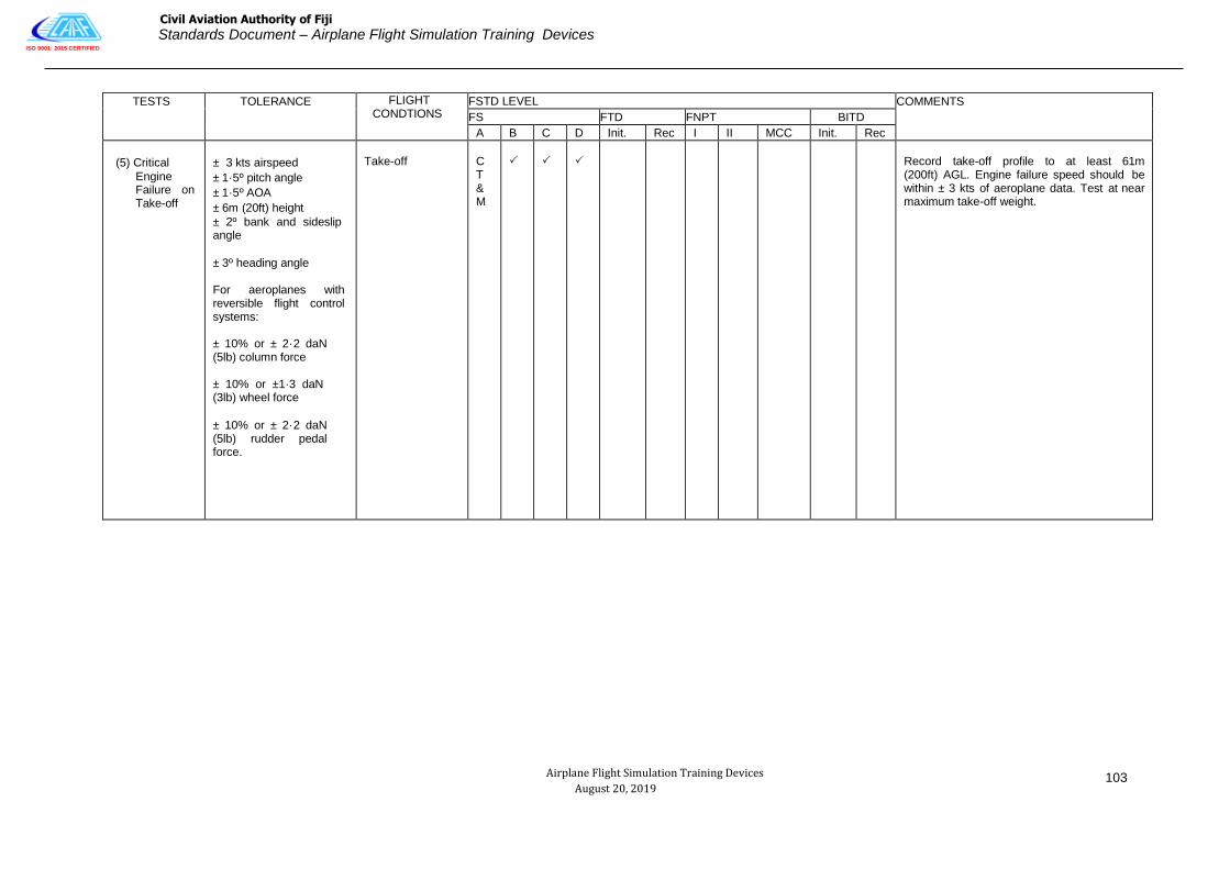
ISO 9001: 2015 CERTIFIED
Civil Aviation Authority of Fiji
Standards Document – Airplane Flight Simulation Training Devices
Airplane Flight Simulation Training Devices
August 20, 2019
103
TESTS TOLERANCE FLIGHT CONDTIONS
FSTD LEVEL COMMENTS
FS FTD FNPT BITD
A B C D Init. Rec I II MCC Init. Rec
(5) Critical
Engine Failure on Take-off
± 3 kts airspeed
± 1·5º pitch angle
± 1·5º AOA
± 6m (20ft) height
± 2º bank and sideslip angle
± 3º heading angle
For aeroplanes with reversible flight control systems:
± 10% or ± 2·2 daN (5lb) column force
± 10% or ±1·3 daN (3lb) wheel force
± 10% or ± 2·2 daN (5lb) rudder pedal force.
Take-off
C T & M
Record take-off profile to at least 61m (200ft) AGL. Engine failure speed should be within ± 3 kts of aeroplane data. Test at near maximum take-off weight.

ISO 9001: 2015 CERTIFIED
Civil Aviation Authority of Fiji
Standards Document – Airplane Flight Simulation Training Devices
Airplane Flight Simulation Training Devices
August 20, 2019
104
TESTS TOLERANCE FLIGHT CONDTIONS
FSTD LEVEL COMMENTS
FS FTD FNPT BITD
A B C D Init. Rec I II MCC Init. Rec
(6) Crosswind Take-off.
± 3 kts airspeed
± 1·5º pitch angle
± 1·5º AOA
± 6m (20ft) height
± 2º bank and sideslip angle
± 3º heading
Correct trends at
airspeeds below 40 kts For rudder / pedal and heading.
For aeroplanes with reversible flight control systems:
± 10% or ± 2·2 daN (5lb) column force ± 10% or ±1·3 daN (3lb) wheel force ± 10% or ± 2·2 daN (5lb) rudder pedal force.
Take-off
C T & M
Record take-off profile from brake release to at least 61m (200ft) AGL. Requires test data, Including wind profile, For a crosswind component of at least 60% of the AFM value measured at 10m (33ft) above the runway.
(7) Rejected Take-off
± 5% time or
± 1·5 s
± 7·5% distance or
± 76m (250ft)
Take-off
C T & M
Record near maximum take-off weight. Speed for reject should be at least 80% of V1. Autobrakes will be used where applicable. Maximum braking effort, auto or manual. Time and distance should be recorded from brake release to a full stop.

ISO 9001: 2015 CERTIFIED
Civil Aviation Authority of Fiji
Standards Document – Airplane Flight Simulation Training Devices
Airplane Flight Simulation Training Devices
August 20, 2019
105
TESTS TOLERANCE FLIGHT CONDTIONS
FSTD LEVEL COMMENTS
FS FTD FNPT BITD
A B C D Init. Rec I II MCC Init. Rec
(8) Dynamic Engine Failure after Take- off.
± 20% or ± 20/s body angular rates
Take-off
C T & M
Engine failure speed should be within ± 3 kts of aeroplane data. Engine failure may be a snap deceleration to idle. Record hands off from 5 secs before engine failure to ± 5 secs or 30 deg bank, whichever occurs first.
Note: for safety considerations, aeroplane flight test may be performed out of ground effect at a safe altitude, but with correct aeroplane configuration and airspeed.
CCA: Test in normal AND Non-normal Control State.
c. CLIMB
(1) Normal Climb All Engines Operating
± 3 kts airspeed ± 5% or
± 0·5 m/s
(100 ft/min) R/C
Clean or specified climb configuration
Flight test data or aeroplane performance manual data may be used. Record at nominal climb speed and mid initial climb altitude. FSTD performance to be recorded over an interval of at least 300m (1000ft)
For FTD‘s may be a Snapshot test.

ISO 9001: 2015 CERTIFIED
Civil Aviation Authority of Fiji
Standards Document – Airplane Flight Simulation Training Devices
Airplane Flight Simulation Training Devices
August 20, 2019
106
TESTS TOLERANCE FLIGHT CONDTIONS
FSTD LEVEL COMMENTS
FS
FTD
FNPT
BITD
A B C D Init. Rec I II MCC Init. Rec
(2) One Engine inoperative second segment climb.
± 3 kts airspeed
± 5% or ± 0·5 m/s (100 ft/min) R/C but not less than AFM values.
2nd
Segment Climb
For FNPTs and BITDs Gear up and Take-off Flaps.
C T & M
C T & M
Flight test data or aeroplane performance manual data may be used. Record at nominal climb speed. Flight simulator performance to be recorded over an interval of at least 300m (1000 ft).
Test at WAT (Weight, Altitude or Temperature) limiting condition.
For FTD‘s may be a Snapshot test.
(3) One Engine Inoperative en-route Climb.
± 10% time
± 10% distance
± 10% fuel used
Clean
C T & M
Flight test data or aeroplane performance manual data may be used.
Test for at least a 1 550m (5 000 ft) segment.

ISO 9001: 2015 CERTIFIED
Civil Aviation Authority of Fiji
Standards Document – Airplane Flight Simulation Training Devices
Airplane Flight Simulation Training Devices
August 20, 2019
107
TESTS
TOLERANCE
FLIGHT CONDTIONS
FSTD LEVEL
COMMENTS
FS FTD FNPT BITD
A B C D Init. Rec I II MCC Init.
.
Rec
d. CRUISE / DESCENT
(1) Level Flight Acceleration
± 5% time
Cruise
C T & M
Minimum of 50 kts increase using maximum continuous thrust rating or equivalent.
For very small aeroplanes, speed change may be reduced to 80% of operational speed range.
(2) Level Flight Deceleration
± 5% time
Cruise
C T & M
Minimum of 50 kts decrease using idle power.
For very small aeroplanes, speed change may be reduced to 80% of operational speed range.
(4) One Engine Inoperative Approach Climb for aeroplanes with icing accountability if required by the flight manual for this phase of flight.
± 3 kts airspeed
± 5% or
± 0·5 m/s (100 ft/min) R/C but not less than AFM values.
Approach
Flight test data or aeroplane performance manual data may be used. FSTD performance to be recorded over an interval of at least 300m (1000 ft). Test near maximum certificated landing weight as may be applicable to an approach in icing conditions.
Aeroplane should be configured with all anti-ice and de-ice systems operating normally, gear up and go-around flap. All icing accountability considerations, in accordance with the flight manual for an approach in icing conditions, should be applied.
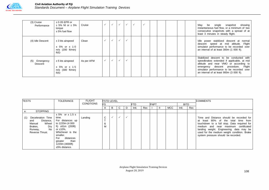
ISO 9001: 2015 CERTIFIED
Civil Aviation Authority of Fiji
Standards Document – Airplane Flight Simulation Training Devices
Airplane Flight Simulation Training Devices
August 20, 2019
108
(3) Cruise
Performance
± 0·05 EPR or
± 5% Nl or ± 5% torque
± 5% fuel flow
Cruise
May be single snapshot showing instantaneous fuel flow, or a minimum of two consecutive snapshots with a spread of at least 3 minutes in steady flight.
(4) Idle Descent
± 3 kts airspeed
± 5% or ± 1·0 m/s (200 ft/min) R/D
Clean
Idle power stabilized descent at normal descent speed at mid altitude. Flight simulator performance to be recorded over an interval of at least 300m (1 000 ft).
(5) Emergency Descent
± 5 kts airspeed
± 5% or ± 1·5 m/s (300 ft/min) R/D
As per AFM
Stabilized descent to be conducted with speedbrakes extended if applicable, at mid altitude and near VMO or according to emergency descent procedure. Flight simulator performance to be recorded over an interval of at least 900m (3 000 ft).
TESTS TOLERANCE FLIGHT
CONDTIONS FSTD LEVEL COMMENTS
FS FTD FNPT BITD
A B C D Init. Rec I II MCC Init. Rec
e. STOPPING
(1) Deceleration Time and Distance, Manual Wheel Brakes, Dry Runway, No Reverse Thrust.
± 5% or ± 1.5 s time. For distances up to 1220m (4 000 ft) ±61m (200ft) or ±10%, Whichever is the smaller. For distances greater than 1220m (4000ft)
±5% distance.
Landing
C T & M
Time and Distance should be recorded for at least 80% of the total time from touchdown to a full stop. Data required for medium and near maximum certificated landing weight. Engineering data may be used for the medium weight condition. Brake system pressure should be recorded.

ISO 9001: 2015 CERTIFIED
Civil Aviation Authority of Fiji
Standards Document – Airplane Flight Simulation Training Devices
Airplane Flight Simulation Training Devices
August 20, 2019
109
(2) Deceleration Time and Distance, Reverse Thrust, No Wheel Brakes, Dry Runway.
± 5% or ± 1.5 s time And the smaller of ±10% or ±61m (200ft) of distance.
Landing
C T & M
Time and distance should be recorded for at least 80% of the total time from initiation of reverse thrust to full thrust reverser minimum operating speed. Data required for medium and near maximum certificated landing weights. Engineering data may be used for the medium weight condition.
(3) Stopping Distance, Wheel Brakes, Wet Runway
± 10% or
±61m (200ft)
distance
Landing
Either flight test or manufacturers performance manual data should be used where available. Engineering data, based on dry runway flight test stopping distance and the effects of contaminated runway braking coefficients, are an acceptable alternative.
(4) Stopping Distance, Wheel Brakes, Icy Runway
± 10% or
±61m (200ft)
distance
Landing
Either flight test or manufacturer‘s performance manual data should be used where available. Engineering data, based on dry runway flight test stopping distance and the effects of contaminated runway braking coefficients, are an acceptable alternative.
TESTS
TOLERANCE
FLIGHT CONDTIONS
FSTD LEVEL
COMMENTS
FS FTD FNPT BITD
A B C D Init. Rec I II MCC Init. Rec
f. ENGINES

ISO 9001: 2015 CERTIFIED
Civil Aviation Authority of Fiji
Standards Document – Airplane Flight Simulation Training Devices
Airplane Flight Simulation Training Devices
August 20, 2019
110
(1) Acceleration
±10% Ti or
±.·25s
±10% Ti
Approach or Landing
C T & M
Ti = Total time from initial throttle movement until a 10% response of a critical engine parameter.
Ti = Total time from initial throttle movement to 90% of go around power. Critical engine parameter should be a measure of power (N1, N2, EPR, etc.). Plot from flight idle to go around power for a rapid throttle movement.
FTD, FNPT and BITD only: CT&M acceptable.
(2) Deceleration
±10% Ti or
±0.·25s
±10% Ti
Ground
C T & M
Ti= Total time from initial throttle movement until a 10% response of a critical engine parameter.
Ti= Total time from initial throttle movement to 90% decay of maximum take-off power. Plot from maximum take- off power to idle for a rapid throttle movement.
FTD, FNPT and BITD only: CT&M acceptable.
TESTS TOLERANCE FLIGHT CONDTIONS
FSTD LEVEL COMMENTS
FS FTD FNPT BITD
A B C D Init. Rec I II MCC Init. Rec
2. HANDLING QUALITIES

ISO 9001: 2015 CERTIFIED
Civil Aviation Authority of Fiji
Standards Document – Airplane Flight Simulation Training Devices
Airplane Flight Simulation Training Devices
August 20, 2019
111
(A) STATIC CONTROL CHECKS
NOTE: Pitch, roll and yaw controller position versus force or time shall be measured at the control. An alternative method would be to instrument the FSTD in an equivalent manner to the flight test aeroplane. The force and position data from this instrumentation can be directly recorded and matched to the aeroplane data. Such a permanent installation could be used without anytime for installation of external devices.
CCA: Testing of position versus force is not applicable if forces are generated solely by use of aeroplane hardware in the FSTD.
(1) Pitch Controller Position versus Force and Surface Position Calibration
±0·9 daN (2lbs) breakout
±2·2 daN (5lbs) or
±10% force.
±2º elevator angle
Ground
C T & M
Uninterrupted control sweep to stops should be validated (where possible) with in-flight data from tests such as longitudinal static stability, stall, etc. Static and dynamic flight control tests should be accomplished at the same feel or impact pressures.
Column Position versus force only
±2·2 daN (5lbs) or
±10% force
Cruise or Approach
C T & M
FNPTs level 1 and BITDs: Control forces and travel shall broadly correspond to that of the replicated class of aeroplane.
(2) Roll Controller Position vs. Force and Surface Position Calibration
±0·9 daN (2lbs) breakout
±1·3 daN (3lbs) or
±10% force.
±2º aileron angle
±3º spoiler angle
Ground
C T & M
Uninterrupted control sweep to stops. Should be validated with in-flight data from tests such as engine out trims, steady state sideslips, etc. Static tests should be accomplished at the same feel or impact pressures.
TESTS
TOLERANCE
FLIGHT CONDTIONS
FSTD LEVEL
COMMENTS
FS FTD FNPT BITD
A B C D Init. Rec I II MCC Init. Rec

ISO 9001: 2015 CERTIFIED
Civil Aviation Authority of Fiji
Standards Document – Airplane Flight Simulation Training Devices
Airplane Flight Simulation Training Devices
August 20, 2019
112
Wheel Position vs. Force only.
± 1.3daN (3lbs) Or
±10% Force
Cruise or Approach
C T & M
FNPT 1 and BITD: Control forces and travel shall broadly correspond to that of the replicated class of aeroplane.
(3) Rudder Pedal Position vs. Force and Surface Position Calibration.
±2·2 daN (5lbs) breakdown
±2·2 daN (5lbs) or
±10% force ± 20 rudder angle
Ground
C T & M
Uninterrupted control sweep to stops. Should be validated with in flight data from tests such as engine out trims, steady state sideslips, etc. Static and dynamic flight control tests should be accomplished at the same feel or impact pressures.
Pedal Position vs. Force only.
±2·2 daN (5lbs) or
±10% force.
Cruise or Approach
C T & M
FNPT1 and BITD: Control forces and travel shall broadly correspond to that of the replicated class of aeroplane.
(4) Nosewheel Steering and Position Calibration
±0·9 daN (2lbs) breakout
±1·3 daN (3lbs) or
±10% force.
±2º NWA
Ground C T & M
Uninterrupted control sweep to stops.
(5) Rudder Pedal Steering Calibration
±2º NWA Ground C T & M
Uninterrupted control sweep to stops
(6) Pitch Trim Indicator vs. Surface Position Calibration
±0·5º trim angle Ground
Purpose of test is to compare flight simulator against design data or equivalent.
±1º trim angle Ground
C T & M
BITD: Only applicable if appropriate trim settings are available, e.g. data from the AFM.
TESTS TOLERANCE FLIGHT CONDTIONS
FSTD LEVEL COMMENTS
FS FTD FNPT BITD
A B C D Init. Rec I II MCC Init. Rec

ISO 9001: 2015 CERTIFIED
Civil Aviation Authority of Fiji
Standards Document – Airplane Flight Simulation Training Devices
Airplane Flight Simulation Training Devices
August 20, 2019
113
(7) Pitch Trim Rate
± 10% or ± 0·5 deg/s trim rate (º/s)
Ground and approach
Trim rate to be checked at pilot primary induced trim rate (ground) and autopilot or pilot primary trim rate in flight at go-around flight conditions.
(8) Alignment of Cockpit Throttle Lever vs. Selected Engine Parameter
± 5º of TLA or
± 3% N1 or
± 0·03 EPR or
± 3% torque
For propeller-driven aeroplanes, where the propeller levers do not have angular travel, a tolerance of ± 2cm (±
0.8 in) applies.
Ground
Simultaneous recording for all engines. The tolerances apply against aeroplane data and between engines.
For aeroplanes with throttle detents, all detents to be presented.
In the case of propeller-driven aeroplanes, if an additional level, usually referred to as the propeller lever is present, it should also be checked.
Where these levers do not have angular travel a tolerance of ± 2cm (± 0·8 inches) applies.
May be a series of Snapshot tests.
(9) Brake Pedal Position vs. Force and Brake System Pressure Calibration
±2·2 daN (5lbs) or
±10% force.
± 1·0 MPa (150 psi) or
± 10% brake system pressure.
Ground
C T & M
Flight simulator computer output results may be used to show compliance.
Relate the hydraulic system pressure to pedal position in a ground static test.
TESTS TOLERANCE FLIGHT CONDTIONS
FSTD LEVEL COMMENTS
FS FTD FNPT BITD
A B C D Init. Rec I II MCC Init. Rec

ISO 9001: 2015 CERTIFIED
Civil Aviation Authority of Fiji
Standards Document – Airplane Flight Simulation Training Devices
Airplane Flight Simulation Training Devices
August 20, 2019
114
(10) Stick pusher system force calibration (if applicable).
± 10% or ± 5 lb (2.2 daN)
stick/column transient
force.
Ground or flight
This test is intended to validate the stick/column transient force resulting from a stick pusher system activation.
This test may be conducted in an on-ground condition through stimulation of the stall protection system in a manner that generates a stick pusher response representative of an in-flight condition.
Aeroplane manufacturer design data may be utilized as validation data, if acceptable to the competent authority.
The test provisions may be met through column force validation testing in conjunction with the stall characteristics test (please refer to AC1 SD FSTD (A).030(2) (c) (8)).
This test is required only for FSTDs that are to be qualified to conduct full stall training tasks.
TESTS TOLERANCE FLIGHT
CONDTIONS FSTD LEVEL COMMENTS
FS FTD FNPT BITD

ISO 9001: 2015 CERTIFIED
Civil Aviation Authority of Fiji
Standards Document – Airplane Flight Simulation Training Devices
Airplane Flight Simulation Training Devices
August 20, 2019
115
A B C D Init. Rec I II MCC Init. Rec
B. DYNAMIC CONTROL CHECKS
Tests 2b1, 2b2, and 2b3 are not applicable if dynamic response is generated solely by use of aeroplane hardware in the flight simulator. Power setting may be that required for level flight unless otherwise specified.
TESTS TOLERANCE FLIGHT CONDTIONS
FSTD LEVEL COMMENTS
FS FTD FNPT BITD
A B C D Init. Rec I II MCC Init. Rec
(1) Pitch Control l
For underdamped systems:
± 10% of time from 90% of initial displacement (Ad) to first zero crossing and ± 10 (n+1) % of period thereafter.
±10% amplitude of first overshoot applied to all overshoots greater than 5% of initial displacement (Ad).
±1 overshoot (first significant overshoot should be matched)
For over damped systems:
± 10% of time from 90% of initial displacement (Ad) to 10% of initial displacement (0·1 Ad).
Take-off, Cruise and Landing
Data should be for normal control displacements in both directions (approximately 25% to 50% full throw or approximately 25% to 50% of maximum allowable pitch controller deflection for flight conditions limited by the maneuvering load envelope). Tolerances apply against the absolute values of each period (considered independently).
n = The sequential period of a full oscillation.
Refer to AC 1 SD FSTD (A) .030 (b) (4) (i).
TESTS TOLERANCE FLIGHT CONDTIONS
FSTD LEVEL COMMENTS
FS FTD FNPT BITD

ISO 9001: 2015 CERTIFIED
Civil Aviation Authority of Fiji
Standards Document – Airplane Flight Simulation Training Devices
Airplane Flight Simulation Training Devices
August 20, 2019
116
A B C D Init. Rec I II MCC Init. Rec
(2) Roll Control.
For under damped systems:
±10% of time from 90% of initial displacement (Ad) to first zero crossing and ± 19 (n+1) % of period thereafter.
±10% amplitude of first overshoot applied to all overshoots greater than 5% of initial displacement (Ad).
± 1 overshoot (first significant overshoot should be matched)
For over damped systems:
± 10% of time from 90% of initial displacement (Ad) to 10% of initial displacement (0·1Ad).
Take-off, Cruise and Landing
Data should be for normal control displacement (approximately 25% to 50% of full throw or approximately 25% to 50% of maximum allowable roll controller deflection for flight conditions limited by the maneuvering load envelope).
Refer to AC 1 SD FSTD (A) .030 (b) (4) (i).
TESTS TOLERANCE FLIGHT CONDTIONS
FSTD LEVEL COMMENTS
FS FTD FNPT BITD
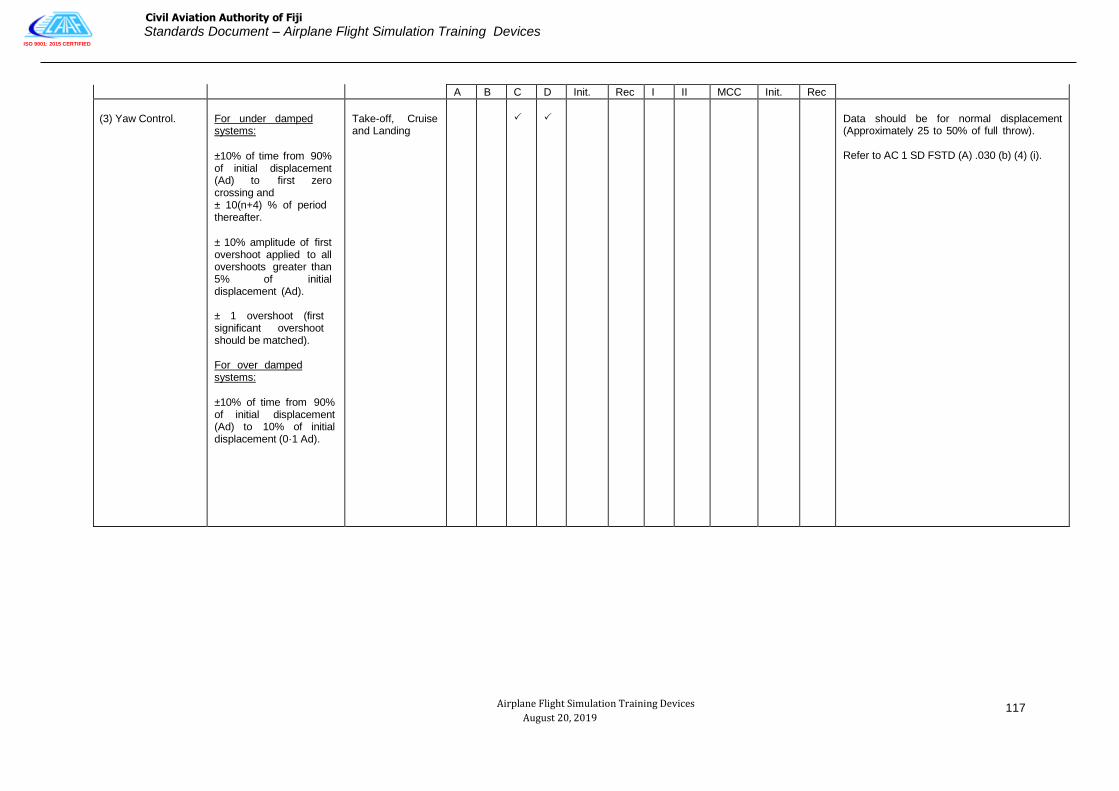
ISO 9001: 2015 CERTIFIED
Civil Aviation Authority of Fiji
Standards Document – Airplane Flight Simulation Training Devices
Airplane Flight Simulation Training Devices
August 20, 2019
117
A B C D Init. Rec I II MCC Init. Rec
(3) Yaw Control.
For under damped systems:
±10% of time from 90% of initial displacement (Ad) to first zero crossing and ± 10(n+4) % of period thereafter.
± 10% amplitude of first overshoot applied to all overshoots greater than 5% of initial displacement (Ad).
± 1 overshoot (first significant overshoot should be matched).
For over damped systems:
±10% of time from 90% of initial displacement (Ad) to 10% of initial displacement (0·1 Ad).
Take-off, Cruise and Landing
Data should be for normal displacement (Approximately 25 to 50% of full throw).
Refer to AC 1 SD FSTD (A) .030 (b) (4) (i).

ISO 9001: 2015 CERTIFIED
Civil Aviation Authority of Fiji
Standards Document – Airplane Flight Simulation Training Devices
Airplane Flight Simulation Training Devices
August 20, 2019
118
TESTS TOLERANCE FLIGHT CONDTIONS
FSTD LEVEL COMMENTS
FS FTD FNPT BITD
A B C D Init. Rec I II MCC Init. Rec
(4) Small Control Inputs - pitch.
±0·15º/s body pitch rate or ±20% of peak body pitch rate applied throughout the time history.
Approach or Landing
Control inputs should be typical of minor corrections made while established on an ILS approach (approximately 0·5 to 2º.s pitch rate). Test in both directions. Show time history data from 5 seconds before until at least 5 seconds after initiation of control input.
CCA: Test in normal AND non-normal control state.
(5) Small Control Inputs – roll
±0·15º/s body roll rate or ± 20% of peak body roll rate applied throughout the time history
Approach or Landing
Control inputs should be typical of minor corrections made while established on an ILS approach (approximately 0·5 to 2º/s roll rate.) Test in one direction. For aeroplane’s that exhibit non-symmetrical behavior, test in both directions. Show time history data from 5 seconds before until at least 5 seconds after initiation of control input.
CCA: Test in normal AND non-normal control state.

ISO 9001: 2015 CERTIFIED
Civil Aviation Authority of Fiji
Standards Document – Airplane Flight Simulation Training Devices
Airplane Flight Simulation Training Devices
August 20, 2019
119
TESTS TOLERANCE FLIGHT
CONDTIONS FSTD LEVEL COMMENTS
FS FTD FNPT BITD
A B C D Init. Rec I II MCC Init. Rec
(6) Small Control Inputs – yaw
±0·15º/s body yaw rate or ±20% of peak body yaw rate applied throughout the time history.
Approach or Landing
Control inputs should be typical of minor corrections made while established on an ILS approach (approximately 0·5 to 2º.s yaw rate). Test in one direction. For aeroplanes that exhibit non-symmetrical behavior, test in both directions. Show time history data from 5 seconds before until at least 5 seconds after initiation of control input.
CCA: Test in normal AND non-normal control state.

ISO 9001: 2015 CERTIFIED
Civil Aviation Authority of Fiji
Standards Document – Airplane Flight Simulation Training Devices
Airplane Flight Simulation Training Devices
August 20, 2019
120
TESTS TOLERANCE FLIGHT CONDTIONS
FSTD LEVEL COMMENTS
FS FTD FNPT BITD
A B C D Init. Rec I II MCC Init. Rec
c. LONGITUDINAL Power setting may be that required for level flight unless otherwise specified.
(1) Power Change Dynamics
±3kts airspeed
±30m (100ft)
altitude
±1·5º or ± 20% pitch angle
Approach
C T & M
Power change from thrust for approach or level flight to maximum continuous or go-around power. Time history of uncontrolled free response for a time increment equal to at least 5 secs before initiation of the power change to completion of the power change + 15 secs.
CCA: Test in normal AND non-normal Control state.
Power Change Force
± 2·2daN (5lbs) or
±10% force
Approach
For an FNPT l e v e l I and a BITD the power change force test only is acceptable.
(2) Flap Change Dynamics
±3kts airspeed
±30m (100ft)
altitude
±1·5º or
±20% pitch angle
Take-off through initial flap retraction and approach to landing
C T & M
Time history of uncontrolled free response for a time increment equal to at least 5 secs before initiation of the reconfiguration change to completion of the reconfiguration change +15 secs.
CCA: Test in normal and non-normal Control state.
Flap Change Force
±2·2daN (5lbs) or
±10% Force
C T & M
For an FNPT I and BITD the flap change force test only is acceptable.

ISO 9001: 2015 CERTIFIED
Civil Aviation Authority of Fiji
Standards Document – Airplane Flight Simulation Training Devices
Airplane Flight Simulation Training Devices
August 20, 2019
121
TESTS TOLERANCE FLIGHT CONDTIONS
FSTD LEVEL COMMENTS
FS FTD FNPT BITD
A B C D Init. Rec I II MCC Init. Rec
(3) Spoiler /
Speedbrake Change Dynamics
±3kts airspeed
±30m (100ft)
altitude
±1·5º or ± 20% pitch angle
Cruise
C T & M
Time history of uncontrolled free response for a time increment equal to at least 5 secs before initiation of the reconfiguration change to completion of the reconfiguration change +15 secs.
Results required for both extension and retraction.
CCA: Test in normal and non-normal Control state.
(4) Gear Change Dynamics
±3kts airspeed
±30m (100ft)
altitude
±1·5º or
±20% pitch angle
For FNPTs and BITDs, ±20 or ±20%
pitch angle
Take-off (retraction) and Approach (extension)
C T & M
Time history of uncontrolled free response for a time increment equal to at least 5 secs before initiation of the configuration change to completion of the reconfiguration change +15 secs.
CCA: Test in normal and non-normal Control State.
Gear Change Force
±2·2daN (5lbs) or
±20% Force
Take-off and Approach
C T & M
For an FNPT I and BITD the gear change force test only is acceptable.
(5) Longitudinal Trim
±1º elevator
±0·5º stabilizer
±1º pitch angle ±5% net thrust or equivalent
Cruise, Approach and Landing
C T & M
Steady-state wings level trim with thrust for level flight. May be a series of snapshot tests.
CCA: Test in normal OR non-normal Control State

ISO 9001: 2015 CERTIFIED
Civil Aviation Authority of Fiji
Standards Document – Airplane Flight Simulation Training Devices
Airplane Flight Simulation Training Devices
August 20, 2019
122
TESTS TOLERANCE FLIGHT CONDTIONS
FSTD LEVEL COMMENTS
FS FTD FNPT BITD
A B C D Init. Rec I II MCC Init. Rec
±2 deg Pitch Control (Elevator & Stabilizer)
±2 deg Pitch
±5% Power or Equivalent
Cruise, Approach
C T & M
May be a series of Snapshot tests.
FNPT I and BITD may use equivalent stick and trim controllers.
(6) Longitudinal Maneuvering Stability (Stick Force e.g.)
.
±2.2 daN (5lbs) or
±10% pitch controller force
Alternative method:
±10 or ±10% change of elevator.
Cruise, Approach and Landing
C T & M
Continuous time history data or a series of snapshot tests may be used. Test up to approximately 300 of bank for approach and landing configurations.
Test up to approximately 450 of bank for the cruise configuration. Force tolerance not applicable if forces are generated solely by the use of aeroplane hardware in the FSTD. Alternative method applies to aeroplanes which do not exhibit stick- force-per-g characteristics.
CCA: Test in normal and non-normal Control State as applicable.
(7) Longitudinal Static Stability
±2·2 daN (5lbs) or ±10% pitch controller force.
Alternative method:
±1º or ±10% change of elevator.
Approach
C T & M
C T & M
Data for at least two speeds above and two speeds below trim speed. May be a series of snapshot tests. Force tolerance not applicable if forces are generated solely by the use of aeroplane hardware in the FSTD. Alternative method applies to aeroplanes which do not exhibit speed stability characteristics. CCA: Test in normal OR non-normal Control State
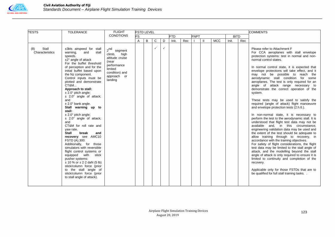
ISO 9001: 2015 CERTIFIED
Civil Aviation Authority of Fiji
Standards Document – Airplane Flight Simulation Training Devices
Airplane Flight Simulation Training Devices
August 20, 2019
123
TESTS TOLERANCE FLIGHT
CONDTIONS FSTD LEVEL COMMENTS
FS FTD FNPT BITD
A B C D Init. Rec I II MCC Init. Rec
(8) Stall Characteristics
±3kts airspeed for stall warning, and stall speeds. ±2° angle of attack For the buffet threshold of perception and for the initial buffet based upon the Nz component. Control inputs must be plotted and demonstrate CT&M... Approach to stall: ± 2.0° pitch angle; ± 2.0° angle of attack; and ± 2.0° bank angle. Stall warning up to stall: ± 2.0° pitch angle; ± 2.0° angle of attack; and CT&M for roll rate and yaw rate. Stall break and recovery: see AMC10 FSTD (A).300. Additionally, for those simulators with reversible flight control systems or equipped with stick pusher systems: ± 10 % or ± 2·2 daN (5 lb) stick/column force (prior to the stall angle of stick/column force (prior to stall angle of attack).
2nd
segment climb, high altitude cruise (near performance limited condition) and approach or landing
Please refer to Attachment F For CCA aeroplanes with stall envelope protection systems: test in normal and non-normal control states. In normal control state, it is expected that envelope protections will take effect, and it may not be possible to reach the aerodynamic stall condition for some aeroplanes. The test is only required for an angle of attack range necessary to demonstrate the correct operation of the system. These tests may be used to satisfy the required (angle of attack) flight manoeuvre and envelope protection tests (2.h.6.). In non-normal state, it is necessary to perform the test to the aerodynamic stall. It is understood that flight test data may not be available and, in this circumstance, engineering validation data may be used and the extent of the test should be adequate to allow training through to recovery, in accordance with the training objectives. For safety of flight considerations, the flight test data may be limited to the stall angle of attack, and the modelling beyond the stall angle of attack is only required to ensure it is limited to continuity and completion of the recovery. Applicable only for those FSTDs that are to be qualified for full stall training tasks. .

ISO 9001: 2015 CERTIFIED
Civil Aviation Authority of Fiji
Standards Document – Airplane Flight Simulation Training Devices
Airplane Flight Simulation Training Devices
August 20, 2019
124
(8b) Approach to Stall
Characteristics
±3kts airspeed for stall warning speeds. ±2° angle of attack For initial buffet. ± 2.0° pitch angle; ± 2.0° angle of attack; and ± 2.0° bank angle. Stall warning up to stall: ± 2.0° pitch angle; ± 2.0° angle of attack; Additionally, for those aeroplanes with reversible flight control systems: ± 10 % or ± 2·2 daN (5 lb) stick/column force.
2nd
segment climb, high altitude cruise (near performance limited condition) and approach or landing
See (1)
See (1)
Please refer to Attachment F CCA: Test in normal and non-normal control states. For FTDs, flight conditions required for second-segment climb and approach or landing only. Note (1): For FSTDs not qualified to conduct full stall training tasks.
(9) Phugoid Dynamics
±10% period. ±10% time to % or double amplitude or ±0·02 of damping ratio.
Cruise
Test should include 3 full cycles or that necessary to determine time to % or double amplitude, whichever is less.
CCA: Test in non-normal Control state.
±10% period with representative damping.
Cruise
C T & M
Test should include at least 3 full cycles.
Time history recommended.
(10) Short Period
Dynamics
±1·5º pitch angle or
±2º/s pitch rate.
±0·1g normal acceleration.
Cruise
CCA: Test in normal AND n o n -normal control state.

ISO 9001: 2015 CERTIFIED
Civil Aviation Authority of Fiji
Standards Document – Airplane Flight Simulation Training Devices
Airplane Flight Simulation Training Devices
August 20, 2019
125
TESTS TOLERANCE FLIGHT CONDTIONS
FSTD LEVEL COMMENTS
FS FTD FNPT BITD
A B C D Init. Rec I II MCC Init. Rec
d. LATERAL DIRECTIONAL
Power setting may be that required for level flight unless otherwise specified.
(1) Minimum Control Speed, Air (VMCA or VMCL), per applicable airworthiness standard – Or – low speed engine inoperative handling characteristics in the air.
±3kts airspeed.
Take-off or Landing (whichever is most critical in the aeroplane).
C T & M
C T & M
Minimum speed may be defined by a performance or control limit which prevents demonstration of VMCA or VMCL in the conventional manner. Take-off thrust should be set on the operating engine(s). Time history or snapshot data may be used.
CCA: Test in normal OR non-normal Control state.
FNPTs and BITDs: It is important that there exists a realistic speed relationship between VMCA and Vs for all configurations and in particular the most critical full-power engine-out take-off configurations.
(2) Roll Response (Rate)
±10% or
±2º/sec roll rate
FS only: For aeroplanes with reversible flight control systems: ±10% or ±1·3 daN (3lb) roll controller force.
Cruise and Approach or Landing
C T & M
C T & M
Test with normal roll control displacement (about 30% of maximum control wheel). May be combined with step input of flight deck roll controller test (2d3).

ISO 9001: 2015 CERTIFIED
Civil Aviation Authority of Fiji
Standards Document – Airplane Flight Simulation Training Devices
Airplane Flight Simulation Training Devices
August 20, 2019
126
TESTS TOLERANCE FLIGHT CONDTIONS
FSTD LEVEL COMMENTS
FS FTD FNPT BITD
A B C D Init. Rec I II MCC Init. Rec
(3) Step Input of Cockpit roll Controller (or Roll Overshoot).
10% or
±2º bank angle
Approach or Landing
With wings level, apply a step roll control input using approximately one-third of roll controller travel. At approximately 20º to 30º bank, abruptly return the roll controller to neutral and allow at least 10 seconds of aeroplane free response. May be combined with roll response (rate) test (2d2).
CCA: Test in normal AND non-normal Control state.
(4) Spiral Stability. Correct trend and ±2º or
±10% bank angle in 20 seconds.
If alternate test is used: correct trend and ±2º aileron.
Cruise and Approach or Landing
C T & M
C T & M
C T & M
Aeroplane data averaged from multiple tests may be used. Test for both directions. As an alternative test, show lateral control required to maintain a steady turn with a bank angle of approximately 30º.
CCA: Test in non-normal Control state.
(5) Engine Inoperative Trim
±1º rudder angle or ±1º tab angle or equivalent pedal.
±2º sideslip angle.
2nd
Segment
Climb and
Approach or
Landing
C T & M
Test should be performed in a manner similar
to that for which a pilot is trained to trim an
engine failure condition. 2nd
segment climb
test should be at take-off
Thrust. Approach or landing test should be at thrust for level flight. May be snapshot tests.
(6) Rudder Response.
±2º/s or
±10% yaw rate
Approach or Landing
Test with stability augmentation ON AND OFF.
±2 deg/sec or
±10% yaw rate or heading change
C T & M
C T & M
Test with a step input at approximately 25% of full rudder pedal throw. CCA: Test i n n o r m a l AND n o n -normal Control state.

ISO 9001: 2015 CERTIFIED
Civil Aviation Authority of Fiji
Standards Document – Airplane Flight Simulation Training Devices
Airplane Flight Simulation Training Devices
August 20, 2019
127
TESTS TOLERANCE FLIGHT CONDTIONS
FSTD LEVEL COMMENTS
FS FTD FNPT BITD
A B C D Init. Rec I II MCC Init. Rec
(7) Dutch roll (Yaw Damper OFF).
±0·5s or
±10% of period.
±10% of time to % or double amplitude or
±0·2 of damping ratio.
±20% or ±1s of time difference between peaks of bank and sideslip.
Cruise and Approach or Landing
C T & M
C T & M
C T & M
Test for at least 6 cycles with stability augmentation OFF.
CCA: Test in non-normal Control state.

ISO 9001: 2015 CERTIFIED
Civil Aviation Authority of Fiji
Standards Document – Airplane Flight Simulation Training Devices
Airplane Flight Simulation Training Devices
August 20, 2019
128
TESTS TOLERANCE FLIGHT CONDTIONS
FSTD LEVEL COMMENTS
FS FTD FNPT BITD
A B C D Init. Rec I II MCC Init. Rec
(8) Steady
State Sideslip.
For a given rudder position:
±2º bank angle
±1º sideslip angle
±10% or
±2ºaileron
±10% or
±5º spoiler or equivalent roll controller position or force.
For FFSs representing an aeroplane with reversible flight control systems:
±10% or ±1·3 daN (3lb) wheel force.
±10% or ±2·2 daN (5lb) rudder pedal force.
Approach or Landing
May be a series of snapshot tests using at least two rudder positions (in each direction for propeller-driven aeroplanes) one of which should be near the maximum allowable rudder.
For FNPTs and BITDs a roll controller position tolerance of ±10% or ±5º applies instead of the aileron tolerance.
For a BITD, the force tolerance should be CT&M.
.

ISO 9001: 2015 CERTIFIED
Civil Aviation Authority of Fiji
Standards Document – Airplane Flight Simulation Training Devices
Airplane Flight Simulation Training Devices
August 20, 2019
129
TESTS TOLERANCE FLIGHT CONDTIONS
FSTD LEVEL COMMENTS
FS FTD FNPT BITD
A B C D Init. Rec I II MCC Init. Rec
e. LANDINGS
(1) Normal Landing
±3kts airspeed
±1·5º pitch angle
±1·5º AOA
±3m (10ft) or
±10% of height
For aeroplanes with reversible flight control systems:
±10% or ± 2·2 daN (5lb) column force.
Landing
C T & M
Test from a minimum of 61m (200ft) AGL to Nosewheel touch-down.
Two tests should be shown, including two normal landing flaps (if applicable) one of which should be near maximum certificated landing weight, the other at light or medium weight.
CCA: Test in normal and non-normal Control state if applicable.
(2) Minimum Flap Landing
±3kts airspeed
±1·5º pitch angle
±1·5º AOA
±3m (10ft) or
±10% of height
For aeroplanes with reversible flight control systems:
±10% or ± 2·2 daN (5lb) column force.
Minimum Certified Landing Flap Configuration
Test from a minimum of 61m (200ft) AGL to Nosewheel touchdown.
Test at near maximum landing weight.

ISO 9001: 2015 CERTIFIED
Civil Aviation Authority of Fiji
Standards Document – Airplane Flight Simulation Training Devices
Airplane Flight Simulation Training Devices
August 20, 2019
130
TESTS TOLERANCE FLIGHT CONDTIONS
FSTD LEVEL COMMENTS
FS FTD FNPT BITD
A B C D Init. Rec I II MCC Init. Rec
(3) Crosswind Landing
±3kts airspeed
±1·5º pitch angle
±1·5º AOA
±3m (10ft) or
±10% of height
±2º bank angle
±2º sideslip angle
±3º heading angle
For aeroplanes with reversible flight control systems:
±10% or ± 2·2 daN (5lb) column force.
±10% or ± 1·3 daN (3lb) wheel force.
±10% or ± 2·2 daN (5lb) rudder pedal force.
Landing
Test from a minimum of 61m (200ft) AGL to 50% decrease in main landing gear touch-down speed.
Requires test data, including wind profile, for a crosswind component of at least 60% of AFM value measured at 10m (33ft) above the runway.

ISO 9001: 2015 CERTIFIED
Civil Aviation Authority of Fiji
Standards Document – Airplane Flight Simulation Training Devices
Airplane Flight Simulation Training Devices
August 20, 2019
131
TESTS TOLERANCE FLIGHT CONDTIONS
FSTD LEVEL COMMENTS
FS FTD FNPT BITD
A B C D Init. Rec I II MCC Init. Rec
(4) One Engine Inoperative Landing.
±3kts airspeed
±1·5º pitch angle
±1·5º AOA
±3m (10ft) or
±10% height
±2º bank angle
±2º sideslip angle
±3º heading angle
Landing
Test from a minimum of 61m (200ft) AGL to a 50% decrease in main landing gear touchdown speed.
(5) Autopilot Landing (if applicable).
±1·5m (5ft) flare height
±0·5s or 10% Tf
±0·7 m/s (140 ft/min) R./D at touchdown, ±3m (10ft) lateral deviation during rollout.
Landing
If autopilot provides rollout guidance, record lateral deviation from touchdown to a 50% decrease in main landing gear touchdown speed, Time of autopilot flare mode engage and main gear touchdown should be noted. This test is not a substitute for the ground effects test requirement.
Tf = Duration of Flare.
(6) All engine autopilot Go Around.
±3kts airspeed
±1·5º pitch angle
±1·5º AOA
As per AFM
Normal all engine autopilot go around should be demonstrated (if applicable) at medium weight.
CCA: Test in normal AND non-normal Control state.

ISO 9001: 2015 CERTIFIED
Civil Aviation Authority of Fiji
Standards Document – Airplane Flight Simulation Training Devices
Airplane Flight Simulation Training Devices
August 20, 2019
132
TESTS TOLERANCE FLIGHT CONDTIONS
FSTD LEVEL COMMENTS
FS FTD FNPT BITD
A B C D Init. Rec I II MCC Init. Rec
(7) One-Engine- inoperative Go- Around
±3kts airspeed
±1·5º pitch angle
±1·5º AOA
±2º bank angle
±2º sideslip angle
As per AFM
Engine inoperative go-around required near maximum certificated landing weight with critical engine(s) inoperative, provide one test with autopilot (if applicable) and one without autopilot.
CCA: Non-autopilot test to be conducted in non-normal mode.
(8) Directional Control (Rudder Effectiveness) with Reverse Thrust symmetric)
±5kts airspeed
±2º/s yaw rate
Landing
Apply rudder pedal input in both directions using full reverse thrust until reaching full thrust reverser minimum operating speed.
(9) Directional control (Rudder Effectiveness) with Reverser Thrust (asymmetric)
±5kts airspeed ±3º heading angle
Landing
With full reverse thrust on the operating engine(s), maintain heading with rudder pedal input until maximum rudder pedal input or thrust reverser minimum operating speed is reached.

ISO 9001: 2015 CERTIFIED
Civil Aviation Authority of Fiji
Standards Document – Airplane Flight Simulation Training Devices
Airplane Flight Simulation Training Devices
August 20, 2019
133
TESTS TOLERANCE FLIGHT CONDTIONS
FSTD LEVEL COMMENTS
FS FTD FNPT BITD
A B C D Init. Rec I II MCC Init. Rec
f. GROUND EFFECT
(1) A test to demonstrate Ground Effect
±1º elevator
±0·5º stabilizer angle ±5% net thrust or equivalent
±1º AOA
±1·5m (5ft) or
±10% height
±3kts airspeed
±1º pitch angle
Landing
Refer to AC1 SD FSTD (A).030(b) (4) (ii). A rationale should be provided with justification of results. CCA: Test in normal OR non-normal control state.

ISO 9001: 2015 CERTIFIED
Civil Aviation Authority of Fiji
Standards Document – Airplane Flight Simulation Training Devices
Airplane Flight Simulation Training Devices
August 20, 2019
134
TESTS TOLERANCE FLIGHT CONDTIONS
FSTD LEVEL COMMENTS
FS FTD FNPT BITD
A B C D Init. Rec I II MCC Init. Rec
g. WIND SHEAR
(1) Four Tests, two take-off and two landing with one of each conducted in still air and the other with Wind Shear active to demonstrate Wind Shear models.
None
Take-off and Landing
Wind shear models are required which provide training in the specific skills required for recognition of wind shear phenomena and execution of recovery maneuvers.

ISO 9001: 2015 CERTIFIED
Civil Aviation Authority of Fiji
Standards Document – Airplane Flight Simulation Training Devices
Airplane Flight Simulation Training Devices
August 20, 2019
135
TESTS TOLERANCE FLIGHT CONDTIONS
FSTD LEVEL COMMENTS
FS FTD FNPT BITD
A B C D Init. Rec I II MCC Init. Rec
Wind shear models should be representative of measured or accident derived winds, but may be simplifications which ensure repeatable encounters. For example, models may consist of independent variable winds in multiple simultaneous components. Wind models should be available for the following critical phases of flight:
(1) Prior to take-off rotation
(2) At lift-off
(3) During initial climb
(4) Short final approach
The United Stated Federal Aviation Administration (FAA) Wind shear Training Aid, wind models from the Royal Aerospace Establishment (RAE), the United States Joint Aerodrome Weather studies (JAWS) Project or other recognized sources may be implemented and should be supported and properly referenced in the QTG. Wind models from alternate sources may also be used if supported by aeroplane related data and such data are properly supported and referenced in the QTG. Use of alternate data should be coordinated with the Authority prior to submittal of the QTG for approval.

ISO 9001: 2015 CERTIFIED
Civil Aviation Authority of Fiji
Standards Document – Airplane Flight Simulation Training Devices
Airplane Flight Simulation Training Devices
August 20, 2019
136
TESTS TOLERANCE FLIGHT CONDTIONS
FSTD LEVEL COMMENTS
FS FTD FNPT BITD
A B C D Init. Rec I II MCC Init. Rec
h. FLIGHT AND MANOEUVRE ENVELOPE PROTECTION FUNCTIONS
This paragraph is only applicable to computer-controlled aeroplanes. Time history results of response to control inputs during entry into each envelope protection function (i.e. with normal and degraded control states if function is different) are required. Set thrust as required to reach the envelope protection function.
(1) Overspeed
±5kts airspeed
Cruise
(2) Minimum Speed
±3kts airspeed
Take-off, Cruise and Approach or Landing
(3) Load Factor
±0·1g
Take-off, Cruise
(4) Pitch Angle
±1·5º pitch angle
Cruise, Approach
(5) Bank Angle
±2º or ±10% bank angle
Approach
(6) Angle of Attack
±1·5º AOA
Second Segment Climb and Approach or Landing
i. ENGINE AND AIRFRAME ICING EFFECTS
(1) Engine and airframe icing effects demonstration (high angle of attack)
Take-off o r approach or landing. (1 flight condition, 2 tests: ice on and ice off)
Refer to Attachment F

ISO 9001: 2015 CERTIFIED
Civil Aviation Authority of Fiji
Standards Document – Airplane Flight Simulation Training Devices
Airplane Flight Simulation Training Devices
August 20, 2019
137
TESTS
TOLERANCE
FLIGHT CONDTIONS
FSTD LEVEL
COMMENTS
FS FTD FNPT BITD
A B C D Init. Rec I II MCC Init. Rec
3. MOTION SYSTEM
(a) Frequency response
As specified by the applicant for flight simulator qualification.
Not applicable
Appropriate test to demonstrate t h e frequency response required. See also AC No. 1 to CAAF-FSTD A.030 para 2.4.3.2
(b) Leg Balance
As specified by the applicant for flight simulator qualification.
Not applicable
Appropriate test to demonstrate leg balance required. See also AC No. 1 to CAAF-FSTD A.030 para 2.4.3.2.
(c) Turn-around check
As specified by the applicant for flight simulator qualification.
Not applicable
Appropriate test to demonstrate turn- around required. See also AC No. 1 to CAAF-FSTD A.030 para 2.4.3.2.
(d) Motion effects Refer t o A C No . 1 to CAAF-FSTD
A.030 3.3(n) subjective testing.
(e) Motion System repeatability
±0·5g actual platform linear accelerations
None
Ensure that motion system hardware and software (in normal flight simulator operating mode) continue to perform as originally qualified. Performance changes from the original baseline can be readily identified with this information.
See AC No. 1 to CAAF-FSTD A.030
Para 2.4.3.4.

ISO 9001: 2015 CERTIFIED
Civil Aviation Authority of Fiji
Standards Document – Airplane Flight Simulation Training Devices
Airplane Flight Simulation Training Devices
August 20, 2019
138
TESTS TOLERANCE FLIGHT CONDTIONS
FSTD LEVEL COMMENTS
FS FTD FNPT BITD
A B C D Init. Rec I II MCC Init. Rec
(f) Motion cueing performance signature.
None
Ground and Flight
For a given set of flight simulation critical maneuvers record the relevant motion variables.
These tests should be run with the motion buffet module disabled.
See AC No. 1 to CAAF-FSTD A.030 Para 2.4.3.3.
(g) Characteristic motion vibrations
None
Ground and Flight
The recorded test results for characteristic buffets should allow the comparison of relative amplitude versus frequency.
For atmospheric disturbance testing, general purpose disturbance models that approximate demonstrable flight test data are acceptable.
Principally, the flight simulator results should exhibit the overall appearance and trends of the aeroplane plots, with at least some of the frequency “spikes” being present within 1 or 2 Hz of the aeroplane data.
See AC No. 1 to CAAF-FSTD A.030
Para 2.4.3.5.

ISO 9001: 2015 CERTIFIED
Civil Aviation Authority of Fiji
Standards Document – Airplane Flight Simulation Training Devices
Airplane Flight Simulation Training Devices
August 20, 2019
139
TESTS TOLERANCE FLIGHT CONDTIONS
FSTD LEVEL COMMENTS
FS FTD FNPT BITD
A B C D Init. Rec I II MCC Init. Rec
The following tests with recorded results and an SOC are required for characteristic motion vibrations, which can be sensed at the flight deck where applicable by aeroplane type.
(1) Thrust effects with brakes set
N/A
Ground
Test should be conducted at maximum possible thrust with brakes set.
(2) Landing gear extended buffet.
N/A
Flight
Test condition should be for a normal operational speed and not at the gear limiting speed.
(3) Flaps extended buffet.
N/A
Flight
Test condition should be for normal operational speed and not at the flap limiting speed.
(4) Speed-brake deployed buffet.
N/A
Flight

ISO 9001: 2015 CERTIFIED
Civil Aviation Authority of Fiji
Standards Document – Airplane Flight Simulation Training Devices
Airplane Flight Simulation Training Devices
August 20, 2019
140
TESTS TOLERANCE FLIGHT CONDTIONS
FSTD LEVEL COMMENTS
FS FTD FNPT BITD
A B C D Init. Rec I II MCC Init. Rec
(5) Stall buffet.
N/A
Cruise, (high altitude), second segment climb, and approach or landing
Test required only for FSTDs that are to be qualified for full stall training tasks or for those aeroplanes which exhibit stall buffet before the activation of the stall warning system. Tests must be conducted for an angle of attack range between the buffet threshold of perception to the pilot and the stall angle of attack. Post-stall characteristics are not required.
be If stabilized flight data between buffet
threshold of perception and stall angle of attack are not available, PSD analysis should conducted for a time span between initial buffet and stall angle of attack. Please refer to the table of functions and subjective tests: AC1 SD FSTD (A).300, Test 3.n. (6).
(6) High speed buffet.
N/A
Flight
Test condition should be for high speed maneuver buffet/wind-up-turn or alternatively Mach buffet.
(7) In-flight
vibrations
N/A
Flight (clean configuration)
Test should be conducted to be representative of in-flight vibrations for propeller driven aeroplanes.

ISO 9001: 2015 CERTIFIED
Civil Aviation Authority of Fiji
Standards Document – Airplane Flight Simulation Training Devices
Airplane Flight Simulation Training Devices
August 20, 2019
141
TESTS TOLERANCE FLIGHT CONDTIONS
FSTD LEVEL COMMENTS
FS FTD FNPT BITD
A B C D Init. Rec I II MCC Init. Rec
4.VISUAL SYSTEM
a. SYSTEM RESPONSE TIME
(1) Transport Delay.
150 milliseconds or less after controller movement.
300 milliseconds or less after controller movement.
Pitch, roll and yaw.
One separate test is required in each axis.
See Appendix 5 to AC FSTD A.030.
FNPT 1 and BITD only the instrument response time applies.
--Or—
(2) Latency
-150 milliseconds or less after controller movement.
-300 milliseconds or less after controller movement.
Take-off, Cruise, and Approach or Landing.
One test is required in each axis (pitch, roll, and yaw) for each of the 3 conditions compared with aeroplane data for a similar input. The visual scene or test pattern used during the response testing shall be representative of the required system capacities to meet the daylight, twilight (dusk/dawn) and night visual capability as applicable.
FS only: Response tests should be confirmed in daylight, twilight and night settings as applicable.
FNPT 1 and BITD only the instrument response time applies.

ISO 9001: 2015 CERTIFIED
Civil Aviation Authority of Fiji
Standards Document – Airplane Flight Simulation Training Devices
Airplane Flight Simulation Training Devices
August 20, 2019
142
TESTS TOLERANCE FLIGHT CONDTIONS
FSTD LEVEL COMMENTS
FS FTD FNPT BITD
A B C D Init. Rec I II MCC Init. Rec
b. DISPLAY SYSTEM TESTS
(1)
(a)
Continuous collimated cross-cockpit visual field of view
Continuous, cross- cockpit, minimum collimated visual field of view providing each pilot with 180 degrees horizontal and 40 degrees vertical field of view.
Horizontal FOV: Not less than a total of 176 measured degrees (including not less than ±88 measured degrees either side of the centre of the design eye point).
Vertical FOV: Not less than a total of 36 measured degrees from the pilot‘s and co- pilot‘s eye point.
Not applicable
Field of view should be measured using a visual test pattern filling the entire visual scene (all channels) consisting of a matrix of black and white 5º squares. Installed alignment should be confirmed in a Statement of Compliance.
(b)
Continuous collimated visual field of view
Continuous, minimum collimated visual field of view providing each pilot with 45 degrees horizontal and 30 degrees vertical field of view.
Not applicable
30 degrees vertical field of view may be insufficient to meet the requirements of AC No. 1 to CAAF-FSTD A.030 Table 2.3 paragraph 4.c (visual ground segment.

ISO 9001: 2015 CERTIFIED
Civil Aviation Authority of Fiji
Standards Document – Airplane Flight Simulation Training Devices
Airplane Flight Simulation Training Devices
August 20, 2019
143
TESTS TOLERANCE FLIGHT CONDTIONS
FSTD LEVEL COMMENTS
FS FTD FNPT BITD
A B C D Init. Rec I II MCC Init. Rec
(2)System Geometry
5º even angular spacing within ±1º as measured from either pilot eye- point, and within 1·5º for adjacent squares.
Not applicable
System geometry should be measured using a visual test pattern filling the entire visual scene (all channels) consisting of a matrix of black and white 5º squares with light points at the intersections. The operator should demonstrate that the angular spacing of any chosen 5º square and the relative spacing of adjacent squares are within the stated tolerances. The intent of this test is to demonstrate local linearity of the displayed image at either pilot eye-point.
(3) Surface Contrast Ratio
Not less than 5:1
Not applicable
Surface contrast ratio should be measured using a raster drawn test pattern filling the entire visual scene (all channels). The test pattern should consist of black and white squares, 5 per square with a white square in the centre of each channel.
Measurement should be made on the centre bright square for each channel using a 1º spot photometer. This value should have a minimum brightness of 7 cd/m² (2 foot-lamberts). Measure any adjacent dark squares. The contrast ratio is the bright square value divided by the dark square value.
Note: during contrast ratio testing, simulator aft-cab and flight deck ambient light levels should be zero.

ISO 9001: 2015 CERTIFIED
Civil Aviation Authority of Fiji
Standards Document – Airplane Flight Simulation Training Devices
Airplane Flight Simulation Training Devices
August 20, 2019
144
TESTS TOLERANCE FLIGHT CONDTIONS
FSTD LEVEL COMMENTS
FS FTD FNPT BITD
A B C D Init. Rec I II MCC Init. Rec
(4) Highlight
Brightness
Not less than 20 cd/m² (6ft-lamberts) on the display
Not applicable
Highlight brightness should be measured by maintaining the full test pattern described in paragraph 4.b 3) above, superimposing a highlight on the centre white square of each channel and measuring the brightness using the 1º spot photometer. Light points are not acceptable. Use of calligraphic capabilities to enhance raster brightness is acceptable.
(5) Vernier
Resolution
Not greater than 2 arc minutes
Not applicable
Vernier resolution should be demonstrated by a test of objects shown to occupy the required visual angle in each visual display used on a scene from the pilot‘s eye-point. The eye will subtend two arc minutes (arc tan [4/6 876] x 60) when positioned on a 3 degree glideslope, 6 876 ft slant range from the centrally located threshold of a black runway surface painted with white threshold bars that are 16ft wide with 4 ft gaps in-between. This should be confirmed by calculations in a statement of compliance.
(6) Light point Size
Not greater than 5 arc minutes
Not applicable
Light point size should be measured using a test pattern consisting of a centrally located single row of light points reduced in length until modulation is just discernible in each visual channel. A row of 48 lights will form a 4º angle or less.

ISO 9001: 2015 CERTIFIED
Civil Aviation Authority of Fiji
Standards Document – Airplane Flight Simulation Training Devices
Airplane Flight Simulation Training Devices
August 20, 2019
145
TESTS TOLERANCE FLIGHT CONDTIONS
FSTD LEVEL COMMENTS
FS FTD FNPT BITD
A B C D Init. Rec I II MCC Init. Rec
(7) Light point Contrast Ration
Not less than 10:1
Not less than 25:1
Not applicable
Light point contrast ratio should be measured using a test pattern demonstrating a 1º area filled with light points (i.e. light point modulation just discernible) and should be compared to the adjacent background.
Note: During contrast ratio testing, simulator aft-cab and flight deck ambient light levels should be zero.

ISO 9001: 2015 CERTIFIED
Civil Aviation Authority of Fiji
Standards Document – Airplane Flight Simulation Training Devices
Airplane Flight Simulation Training Devices
August 20, 2019
146
TESTS TOLERANCE FLIGHT CONDTIONS
FSTD LEVEL COMMENTS
FS FTD FNPT BITD
A B C D Init. Rec I II MCC Init. Rec
c
VISUAL GROUND SEGMENT
Near end. The lights computed to be visible should be visible in the FSTD.
Far end: ±20% of the computed VGS.
Trimmed in the landing configuration at 30m (100ft) wheel height above touchdown zone elevation on glide slope at a RVR setting of 300m (1000ft) or 350m (1200ft)
Visual Ground Segment. This test is designed to assess items impacting the accuracy of the visual scene presented to a pilot at DH on an ILS approach. Those items include:
1) RVR,
2) Glideslope (G/S) and localizer modeling accuracy (location and slope) for an ILS,
3) For a given weight, configuration and speed representative of a point within the aeroplane‘s operational envelope for a normal approach and landing.
If non-homogenous fog is used, the vertical variation in horizontal visibility should be described and be included in the slant range visibility calculation used in the VGS computation.
FNPT: if a generic aeroplane is used as the basic model, a generic cut-off angle of 15 deg. Is assumed as an ideal.

ISO 9001: 2015 CERTIFIED
Civil Aviation Authority of Fiji
Standards Document – Airplane Flight Simulation Training Devices
Airplane Flight Simulation Training Devices
August 20, 2019
147
TESTS TOLERANCE FLIGHT CONDTIONS
FSTD LEVEL COMMENTS
FS FTD FNPT BITD
A B C D Init. Rec I II MCC Init. Rec
5. SOUND SYSTEMS
All tests in this section should be presented using an unweighted 1/3- octave band format from band 17 to 42 (50 Hz to 16 kHz). A minimum 20 second average should be taken at the location corresponding to the aeroplane data set. The aeroplane and flight simulator results should be produced using comparable data analysis techniques.
See AC FSTD A.030
A TURBO-JET AEROPLANES
(1) Ready for engine start
±5dB per 1/3 octave band
Ground
Normal condition prior to engine start. The APU should be on if appropriate.
(2) All engines at idle
±5dB per 1/3 octave band
Ground
Normal condition prior to take-off.
(3) All engines at maximum allowable thrust with brakes set
±5dB per 1/3 octave band
Ground
Normal condition prior to take-off.
(4) Climb
±5dB per 1/3 octave band
En-route climb
Medium Altitude.
(5) Cruise
±5dB per 1/3 octave band
Cruise
Normal cruise configuration.

ISO 9001: 2015 CERTIFIED
Civil Aviation Authority of Fiji
Standards Document – Airplane Flight Simulation Training Devices
Airplane Flight Simulation Training Devices
August 20, 2019
148
TESTS TOLERANCE FLIGHT CONDTIONS
FSTD LEVEL COMMENTS
FS FTD FNPT BITD
A B C D Init. Rec I II MCC Init. Rec
(6) Speedbrake / spoilers extended (as appropriate)
±5dB per 1/3 octave band
Cruise
Normal and constant speedbrake deflection for descent at a constant airspeed and power setting.
(7) Initial approach
±5dB per 1/3 octave band
Constant airspeed, gear up, flaps / slats as appropriate.
(8) Final approach
±5dB per 1/3 octave band
Ground
Constant airspeed, gear down, full flaps.
b. PROPELLER AEROPLANES
(1) Ready for
engine start
±5dB per 1/3 octave band
Ground
Normal condit ion prior to engine start . The APU should be on if appropriate.
(2) All propellers feathered
±5dB per 1/3 octave band
En-route climb
Normal condition prior to take-off.
(3) Ground idle or equivalent
±5dB per 1/3 octave band
Cruise
Normal condition prior to take-off.
(4) Flight idle or equivalent
±5dB per 1/3 octave band
Normal condition prior to take-off.
(5) All engines at maximum allowable power with brakes set
±5dB per 1/3 octave band
Normal condition prior to take-off.

ISO 9001: 2015 CERTIFIED
Civil Aviation Authority of Fiji
Standards Document – Airplane Flight Simulation Training Devices
Airplane Flight Simulation Training Devices
August 20, 2019
149
TESTS TOLERANCE FLIGHT CONDTIONS
FSTD LEVEL COMMENTS
FS FTD FNPT BITD
A B C D Init. Rec I II MCC Init. Rec
(6) Climb
±5dB per 1/3 octave band
En-route climb
Medium altitude.
(7) Cruise
±5dB per 1/3 octave band
Cruise
Normal cruise configuration.
(8) Initial approach
±5dB per 1/3 octave band
Approach
Constant airspeed, gear up, flaps extended as appropriate, RPM as per operating manual.
(9) Final approach
±5dB per 1/3 octave band
Landing
Constant a i r s p e e d , g e a r d o w n , f u l l flaps, RPM as per operating manual.
c SPECIAL CASES
±5dB per 1/3 octave band
Special cases identified as particularly significant to the pilot, important in training, or unique to a specific aeroplane type or variant.
d FLIGHT SIMULATOR BACKGROUN D NOISE
Initial evaluation: not applicable.
Recurrent evaluation: ±3dB per 1/3 octave band compared to initial evaluation.
Results of the background noise at initial qualification should be included in the QTG document and approved by the qualifying authority. The simulated sound will be evaluated to ensure that the background noise does not interfere with training. Refer to AC FSTD A.030. The Measurements are to be made with the simulation running, the sound muted and a dead cockpit.

ISO 9001: 2015 CERTIFIED
Civil Aviation Authority of Fiji
Standards Document – Airplane Flight Simulation Training Devices
Airplane Flight Simulation Training Devices
August 20, 2019
150
TESTS TOLERANCE FLIGHT CONDTIONS
FSTD LEVEL COMMENTS
FS FTD FNPT BITD
A B C D Init. Rec I II MCC Init. Rec
e FREQUENCY RESPONSE
Initial evaluation: not applicable.
Recurrent evaluation: cannot exceed ±5dB on three consecutive bands when compared to initial evaluation and the average of the absolute differences between initial and recurrent evaluation results cannot exceed 2dB.
Only required if the results are to be used during recurrent evaluations according to AC FSTD A.030. The results shall be acknowledged by the authority at initial qualification.

ISO 9001: 2015 CERTIFIED
Civil Aviation Authority of Fiji
Standards Document – Airplane Flight Simulation Training Devices
Airplane Flight Simulation Training Devices
August 20, 2019
151
15.7 Information for Validation Tests
15.8 Engines
Tests are required to show the response of the critical engine parameter to a rapid throttle movement for an engine acceleration and an engine deceleration. The procedure for evaluating the response is illustrated in Figures B-1 and B-2.
Figure B-1. Engine acceleration
vs
vs
10% of its total response above idle power
90% of its total response above idle power

ISO 9001: 2015 CERTIFIED
Civil Aviation Authority of Fiji
Standards Document – Airplane Flight Simulation Training Devices
Airplane Flight Simulation Training Devices
August 20, 2019
152
Figure B-2. Engine deceleration
15.9 Control dynamics
General
The characteristics of an aircraft flight control system have a major effect on handling qualities. A significant consideration in pilot acceptability of an aircraft is the “feel” provided through the flight controls. Considerable effort is expended on aircraft feel system design so that pilots will be comfortable and will consider the aircraft desirable to fly. In order for a FSTD to be representative, it too should present the pilot with the proper feel – that of the aircraft being simulated. Compliance with the requirement should be determined by comparing a recording of the control feel dynamics of the FSTD to actual aircraft measurements in the take-off, cruise and landing configurations.
a) Recordings such as free response to a pulse or step function are traditionally used to estimate the dynamic properties of electromechanical systems. In any case, the dynamic properties can only be estimated since the true inputs and responses are also only estimated. Therefore, it is imperative that the best possible data be collected since close matching of the FSTD control loading system to the aeroplane
vs
vs
= Critical engine parameter at idle power

ISO 9001: 2015 CERTIFIED
Civil Aviation Authority of Fiji
Standards Document – Airplane Flight Simulation Training Devices
Airplane Flight Simulation Training Devices
August 20, 2019
153
systems is essential. The required control dynamics tests are indicated in 2.b.1 through 2.b.3 of the table of FSTD validation tests.
b) Control dynamics characteristics are usually assessed by measuring the free response of the controls using a step input or pulse input to excite the system. The procedure should be accomplished in the take-off, cruise and landing flight conditions and configurations.
c) For aeroplanes with irreversible control systems, measurements may be obtained on the ground if proper pitot-static inputs are provided to represent airspeeds typical of those encountered in flight. Likewise, it may be shown that for some aeroplanes, take-off, cruise and landing configurations have like effects. Thus, one configuration may suffice. If either or both considerations apply, engineering validation or aeroplane manufacturer rationale should be submitted as justification for ground tests or for eliminating a configuration. For FSTDs requiring static and dynamic tests at the controls, special test fixtures will not be required during initial and upgrade evaluations if the QTG shows both test fixture results and the results of an alternate approach, such as computer plots which were produced concurrently and show satisfactory agreement. Repeat of the alternate method during the initial evaluation would then satisfy this test requirement.
Control Dynamics Evaluation.
The dynamic properties of control systems are often stated in terms of frequency, damping and a number of other traditional measurements which can be found in documents on control systems. In order to establish a consistent means of validating test results for FSTD control loading, criteria are needed that will clearly define the interpretation of the measurements and the tolerances to be applied. Criteria are needed for under damped, critically damped and over-damped systems. In the case of an under damped system with very light damping, the system may be quantified in terms of frequency and damping. In critically damped or over-damped systems, the frequency and damping are not readily measured from a response time history. Therefore, some other measurement should be used.
Tests to verify that control feel dynamics represent the aeroplane should show that the dynamic damping cycles (free response of the controls) match that of the aeroplane within specified tolerances. The method of evaluating the response and the tolerance to be applied is described in the under damped and critically damped cases are as follows:
a) Under-damped Response. Two measurements are required for the period, the time to first zero crossing (in case a rate limit is present) and the subsequent frequency of oscillation. It is necessary to measure cycles on an individual basis in case there are non-uniform periods in the response. Each period will be independently compared with the respective period of the aeroplane control system and, consequently, will enjoy the full tolerance specified for that period.
The damping tolerance should be applied to overshoots on an individual basis. Care should be taken when applying the tolerance to small overshoots since the significance of such overshoots becomes questionable. Only those overshoots larger than 5% of the total initial displacement should be considered. The residual band, labelled T (Ad) in Figure B-3 is ±5% of the initial displacement amplitude Ad from the steady state value of the oscillation, or +/- 0.5% of the total control travel (stop to stop). Only oscillations outside the residual band are considered significant.
When comparing FSTD data to aeroplane data, the process should begin by overlaying or aligning the FSTD and aeroplane displacement values and then

ISO 9001: 2015 CERTIFIED
Civil Aviation Authority of Fiji
Standards Document – Airplane Flight Simulation Training Devices
Airplane Flight Simulation Training Devices
August 20, 2019
154
comparing amplitudes of oscillation peaks, the time of the first zero crossing, and individual periods of oscillation. The FSTD should show the same number of significant overshoots to within one when compared against the aeroplane data. This procedure for evaluating the response is illustrated in Figure B-3 below.
b) Critically damped and over-damped response. Due to the nature of critically damped and overdamped responses (no overshoots), the time to travel from 90 per cent of the initial displacement to 10 per cent of the steady state (neutral point) value should be the same as the aeroplane within ±10 per cent or ±0.05 s. Figure B-4 illustrates the procedure
c) Special considerations. Control systems, which exhibit characteristics other than traditional over-damped or under damped responses should meet specified tolerances. In addition, special consideration should be given to ensure that significant trends are maintained.
Tolerances. The following table summarises the tolerances, T. See figure 1 and 2 for an illustration of the referenced measurements.
T(P0) ± 10% of P0 or ±0.05 s.
T(P1) ± 20% of P1 or ±0.05 s.
T(P2) ± 30% of P2 or ±0.05 s.
T(Pn) ±10 (n+1) % of Pn or ±0.05 s.
T(An) ±1 per cent of Amax, where Amax is the largest amplitude or ±0.5 per cent of the total
control travel (stop to stop).
T(Ad) ±5 per cent of Ad = residual band or ±0.5 per cent of the maximum control travel =
residual band.
±1 significant overshoots (minimum of 1 significant overshoot). Steady state position within residual band.
Note 1 - Tolerances should not be applied on period or amplitude after the last significant overshoot.
Note 2 - Oscillations within the residual band are not considered significant and are not subject to tolerances.

ISO 9001: 2015 CERTIFIED
Civil Aviation Authority of Fiji
Standards Document – Airplane Flight Simulation Training Devices
Airplane Flight Simulation Training Devices
August 20, 2019
155
Figure B-3 Underdamped step response
Ad
0.9 Ad
vs
Time
P

ISO 9001: 2015 CERTIFIED
Civil Aviation Authority of Fiji
Standards Document – Airplane Flight Simulation Training Devices
Airplane Flight Simulation Training Devices
August 20, 2019
156
Figure B-4 Critically damped step response
The following tolerance applies only to the overdamped and critically damped systems.
(See Figure B-4 for an illustration of the reference measurement):
T (P0) ±10 per cent of P0 or ±0.05 s.
Alternate Method for Control Dynamics Evaluation of Irreversible Flight Controls.
One aeroplane manufacturer has proposed, and its CAA has accepted, an alternate means for dealing with control dynamics. The method applies to aeroplanes with hydraulically powered flight controls and artificial feel systems. Instead of free response measurements, the system would be validated by measurements of control force and rate of movement.
These tests should be conducted under typical taxi, take-off, cruise and landing conditions. For each axis of pitch, roll and yaw, the control should be forced to its maximum extreme position for the following distinct rates:
a) Static test. Slowly move the control such that approximately 100 seconds are required to achieve a full sweep. A full sweep is defined as movement of the controller from neutral to the stop, usually aft or right stop, then to the opposite stop, then to the neutral position.
b) Slow dynamic test. Achieve a full sweep in approximately 10 seconds.
c) Fast dynamic test. Achieve a full sweep in approximately 4 seconds.
T (P0)
P0
vs

ISO 9001: 2015 CERTIFIED
Civil Aviation Authority of Fiji
Standards Document – Airplane Flight Simulation Training Devices
Airplane Flight Simulation Training Devices
August 20, 2019
157
NOTE: Dynamic sweeps may be limited to forces not exceeding 44·5 daN (100lbs).
Tolerances.
a) Static test. Items 2.a.1, 2.a.2 and 2.a.3 of the table of FSTD validation tests.
b) Dynamic test. ±0.9 daN (2 lbf) or ±10 per cent of dynamic increment above static test.
CAAF is open to alternative means such as the one described above. Such alternatives should, however, be justified and appropriate to the application. For example, the method described here may not apply to all manufacturers’ systems and certainly not to aeroplanes with reversible control systems. Hence, each case should be considered on its own merit on an ad hoc basis. Should the CAA find that alternative methods do not result in satisfactory performance, more conventionally accepted methods should then be used.
Alternate method for control dynamics evaluation of flight controls with atypical response. Dynamic responses exhibiting atypical behaviour, as frequently seen on reversible controls, may be evaluated using an alternate reference line better suited for such cases. This alternate line is based on the dynamic response itself and attempts to better approximate the true rest position of the control throughout the step response.
A full discussion on how to compute the alternate reference line is provided in Attachment N. Figure B-5 shows the final result and how to apply the tolerances using the new reference.
A flight control dynamic response is considered atypical when it does not exhibit classic second order system behaviour. For underdamped systems, the key features of such a behaviour are a constant period, decaying overshoots (an overshoot is always smaller than the previous one) and a fixed steady state position.
Overdamped systems show a control position that will demonstrate a smooth exponential decay from its initial displacement towards a fixed steady state position.
Figure B-5 Tolerances applied using the alternate reference line
line
line

ISO 9001: 2015 CERTIFIED
Civil Aviation Authority of Fiji
Standards Document – Airplane Flight Simulation Training Devices
Airplane Flight Simulation Training Devices
August 20, 2019
158
15.10 Ground Effect
An FSTD to be used for take-off and landing it should faithfully reproduce the aerodynamic changes which occur in ground effect. The parameters chosen for FSTD validation should be indicative of these changes.
A dedicated test should be provided which will validate the aerodynamic ground effect characteristics. The choice of the test method and procedures to validate ground effect rests with the organization performing the flight tests; however, duration of the flight test performed near the ground should be sufficient to validate the ground-effect model.
Acceptable tests for validation of ground effect include:
a) Level fly-bys. The level fly-bys should be conducted at a minimum of three heights within the ground effect, including one at no more than 10% of the wingspan above the ground, one each at approximately 30% and 50% of the wingspan where height refers to main gear tyre above the ground. In addition, one level-flight trim condition should be conducted out of ground effect, e.g. at 150% of wingspan.
b) Shallow approach landing. The shallow approach landing should be performed at a glide slope of approximately one degree with negligible pilot activity until flare.
If other methods are proposed, a rationale should be provided to conclude that the tests performed do validate the ground-effect model.
The lateral-directional characteristics are also altered by ground effect. For example, because of changed in lift, roll damping is affected. The change in roll damping will affect other dynamic modes usually evaluated for FSTD validation. In fact, Dutch roll dynamics, spiral stability, and roll-rate for a given lateral control input are altered by ground effect.
Steady heading sideslips will also be affected. These effects should be accounted for in the FSTD modelling. Several tests such as crosswind landing, one engine inoperative landing, and engine failure on take-off serve to validate lateral-directional ground effect since portions of them are accomplished whilst transiting heights at which ground effect is an important factor.
15.11 Engineering simulator validation data
When a fully flight test validated simulation is modified as a result of changes to the simulated aeroplane configuration, a qualified aeroplane manufacturer may, with the prior agreement of the relevant CAA:
a) Supply validation data from an audited engineering simulator/simulation to selectively supplement flight test data. This arrangement is confined to changes that are incremental in nature and which are both easily understood and well defined; or
b) Support the most recent data package using engineering simulator validation data, and track only the latest version of test requirements.
When the FSTD operator receives appropriate validation data from the approved data provider and receives approval from the CAA, the FSTD operator may adopt tests and associated tolerances described in the current qualification standards as the tests and

ISO 9001: 2015 CERTIFIED
Civil Aviation Authority of Fiji
Standards Document – Airplane Flight Simulation Training Devices
Airplane Flight Simulation Training Devices
August 20, 2019
159
tolerances applicable for the continuing qualification of a previously qualified FSTD. The updated test(s) and tolerance(s) should be made a permanent part of the MQTG.
To be qualified to supply engineering simulator validation data, an aeroplane manufacturer, or other approved data supplier, should:
a) have a proven track record of developing successful data packages;
b) have demonstrated high-quality prediction methods through comparisons of predicted and flight test validated data;
c) have an engineering simulator that:
1. has models which run in an integrated manner;
2. uses the same models as those released to the training community (which are also used to produce stand-alone proof-of-match and check-out documents);
3. is used to support aeroplane development and certification;
d) use the engineering simulation to produce a representative set of integrated proof-of-match cases; and
e) Have an acceptable configuration control system in place covering the engineering simulator and all other relevant engineering simulations.
Aeroplane manufacturers seeking to take advantage of this alternative arrangement should contact the CAA at the earliest opportunity.
For the initial application, each applicant should demonstrate its ability to qualify to the satisfaction of the CAA, in accordance with the means provided in this appendix and Attachment B.
15.12 Motion System
General
Pilots use continuous information signals to regulate the state of the aeroplane. In concert with the instruments and outside-world visual information, whole-body motion feedback is essential in assisting the pilot to control the aeroplane‘s dynamics, particularly in the presence of external disturbances.
The motion system should therefore meet basic objective performance criteria, as well as being subjectively tuned at the pilot‘s seat position to represent the linear and angular accelerations of the aeroplane during a prescribed minimum set of manoeuvers and conditions. Moreover, the response of the motion cueing system should be repeatable.
The objective validation tests presented in this appendix are intended to qualify the FSTD motion cueing system from a mechanical performance standpoint and a motion cueing fidelity perspective.
Motion System Checks.
The intent of tests 3.a (frequency response) and 3.b (turn-around check), as described in the table of FSTD validation tests, is to demonstrate the performance of the motion system hardware and to check the integrity of the motion set-up with regard to calibration and wear. These tests are independent of the motion cueing software and should be considered as robotic tests.

ISO 9001: 2015 CERTIFIED
Civil Aviation Authority of Fiji
Standards Document – Airplane Flight Simulation Training Devices
Airplane Flight Simulation Training Devices
August 20, 2019
160
Motion Cueing Fidelity Tests
Frequency-domain based objective motion cueing test
Background. This test quantifies the response of the motion cueing system from the output of the flight model to the motion platform response. Other motion tests, such as the motion system frequency response, concentrate on the mechanical performance of the motion system hardware alone. The intent of this test is to provide quantitative frequency response records of the entire motion system for specified degree-of-freedom transfer relationships over a range of frequencies.
This range should be representative of the manual control range for that particular aeroplane type and the FSTD as set up during qualification. The measurements of this test should include the combined influence of the motion cueing algorithm, the motion platform dynamics, and the transport delay associated with the motion cueing and control system implementation. Specified frequency responses describing the ability of the FSTD to reproduce aeroplane translations and rotations, as well as the cross-coupling relations, are required as part of these measurements.
When simulating forward aeroplane acceleration, the FSTD is accelerated momentarily in the forward direction to provide the onset cueing. This is considered the direct transfer relation. The FSTD is simultaneously tilted nose-up due to the low-pass filter in order to generate a sustained specific force. The tilt associated with the generation of the sustained specific force, and the angular rates and angular accelerations associated with the initiation of the sustained specific force, are considered cross-coupling relations.
The specific force is required for the perception of the aeroplane sustained specific force, while the angular rates and accelerations do not occur in the aeroplane and should be minimized.
Frequency response test. This test requires the frequency response to be measured for the motion cueing system. Reference sinusoidal signals are inserted at the pilot reference position prior to the motion cueing computations (see Figure B-6). The response of the motion platform in the corresponding degree-of-freedom (the direct transfer relations), as well as the motions resulting from cross-coupling (the cross-coupling relations), are recorded. These are given in Table B-1.
These are the tests that are important to pilot motion cueing and are general tests applicable to all types of aeroplanes. These tests can be run at any time deemed acceptable to the CAA prior to and/or during the initial qualification.
The test requirement can be satisfied by a statement of compliance (SOC) supported with the relevant objective tests and which should be provided by the FSTD manufacturer following factory testing.
It should not be necessary to run these tests for evaluations at the FSTD operator site unless changes are made to the motion cueing algorithms and associated parameters.

ISO 9001: 2015 CERTIFIED
Civil Aviation Authority of Fiji
Standards Document – Airplane Flight Simulation Training Devices
Airplane Flight Simulation Training Devices
August 20, 2019
161
Figure B-6. Schematic of measured input @ and output 0 relation
For frequency-domain motion cueing test.
FSTD response output
Aircraft input signal Pitch Roll Yaw Surge Sway Heave
Pitch 1
2
Roll
3
4
Yaw
5
Surge 7
6
Sway
9
8
Heave
10
Table B-1. Motion cueing system transfer test matrix
The frequency responses describe the relations between aeroplane motions and simulator motions as defined in Table B-1. The relations are explained below per individual test. Tests 1, 3, 5, 6, 8 and 10 show the direct transfer relations, while tests 2, 4, 7 and 9 show the cross-coupling relations.
1) FSTD pitch response to aeroplane pitch input;
2) FSTD surge acceleration response due to aeroplane pitch input;
3) FSTD roll response to aeroplane roll input;
4) FSTD sway specific force response due to aeroplane roll input;
5) FSTD yaw response to aeroplane yaw input;
6) FSTD surge response to aeroplane surge input;
7) FSTD pitch response to aeroplane surge input;
8) FSTD sway response to aeroplane sway input;
9) FSTD roll response to aeroplane sway input; and
10) FSTD heave response to aeroplane heave input.
Frequencies. The tests should be conducted by introducing sinusoidal inputs at discrete input frequencies entered at the output of the flight model, transformed to the pilot
CGAC
to
FPA
Signal
FPS

ISO 9001: 2015 CERTIFIED
Civil Aviation Authority of Fiji
Standards Document – Airplane Flight Simulation Training Devices
Airplane Flight Simulation Training Devices
August 20, 2019
162
reference position just before the motion cueing computations, and measured at the response of the FSTD platform. The twelve discrete frequencies for these tests range from 0.100 rad/s to 15.849 rad/s and are given in Attachment F, Table F-1. The relationship between the frequency and corresponding measured modulus and phase defines the system transfer function. This test requires that, for each degree-of-freedom, measurements at the twelve specified frequencies should be taken.
Input signal amplitudes. The tests applied here to the motion cueing system are intended to qualify its response to normal control inputs during manoeuvring (i.e. not aggressive or excessively hard control inputs). It is necessary to excite the system in such a manner that the response is measured with a high signal-to-noise ratio, and that the possible non-linear elements in the motion cueing system are not overly excited. The sinusoidal input signal amplitudes are defined in Attachment F, Tables F-2 and F-4.
Data recording. The measured parameters for each test should include the modulus and phase as prescribed in Attachment F, 2.2, for the tests delineated in Table B-1. The modulus indicates the amplitude ratio of the output signal divided by the input signal, expressed in non-dimensional terms in case of the direct transfer relations (1, 3, 5, 6, 8, and 10) and in dimensional terms in the case of the cross-coupling relations (2, 4, 7, and 9). The phase describes the delay at that frequency between the output signal and the input signal, and is expressed in degrees.
Frames of reference. Measurements of the FSTD response should be transformed to estimated measurements at the pilot reference frame. This is defined as being attached to the FSTD in the plane of symmetry of the cab, at a height approximately 35 cm below pilot eye height. The x-axis points forward and the z-axis points downward. The frames of reference are defined in Attachment F, 8.4.
Aeroplane characteristics. The tests should be conducted in the FSTD configuration representing the motion drive algorithm during the flight mode. If the motion drive algorithm parameters are different in the ground mode (for example during taxi or take-off roll), the tests should be repeated for this configuration. If to be performed, the recommended conditions on ground are low speed taxi at 10 kt and approach to take-off speed at 80 kt.
Presentation of results. The measured modulus and phase should be tabulated for the twelve discrete frequencies and for each of the transfer relations given in Table B-1. The results should also be plotted for each component in bode plots. The modulus and phase should be presented as a function of frequency in rad/s. The modulus should be presented in a log-log plot, the phase in a semi-log plot. An example is shown in Figure B-7.
Tolerances. The boundaries of the criteria for the ten tests are presented in Attachment F, section 7.

ISO 9001: 2015 CERTIFIED
Civil Aviation Authority of Fiji
Standards Document – Airplane Flight Simulation Training Devices
Airplane Flight Simulation Training Devices
August 20, 2019
163
0.001
Figure B-7. Example bode plots of the frequency response derived from OMCT measurements
Time-domain based objective motion cueing test
A time-domain based objective motion cueing test, which would complement a frequency-domain test, is currently being tested and evaluated by the TDWS (see Appendix D). This test will help quantify the response of the motion cueing system. The testing methodology, criteria and tolerances for this test will be implemented into this section after more testing and when sufficient experience is gained.
Motion system repeatability. The intent of this test is to ensure that the motion system software and motion system hardware have not degraded or changed over time. This will allow an improved ability to determine changes that have adversely affected the training value of the motion as was accepted during the initial qualification. The following information delineates the methodology that should be used for this test:
a) Conditions:
1) one test case on ground: to be determined by the FSTD operator; and
2) One test case in flight: to be determined by the FSTD operator.
b) Input. The inputs should be such that both rotational accelerations/rates and linear accelerations are inserted before the transfer from the aeroplane cg to the pilot reference point with a minimum amplitude of 5 ˚/s2, 10 ˚/s and 0.3 g, respectively, to provide adequate analysis of the output.
c) Recommended output:
1) actual platform linear accelerations; the output will comprise accelerations due to both the linear and rotational motion acceleration; and
0.1 1 1 0 1

ISO 9001: 2015 CERTIFIED
Civil Aviation Authority of Fiji
Standards Document – Airplane Flight Simulation Training Devices
Airplane Flight Simulation Training Devices
August 20, 2019
164
2) Motion actuators position.
Motion vibrations
Presentation of results. The characteristic motion vibrations are a means to verify that the FSTD can reproduce the frequency content of the aeroplane when flown in specific conditions. The test results should be presented as a power spectral density (PSD) plot with frequencies on the horizontal axis and amplitude on the vertical axis. The aeroplane data and FSTD data should be presented in the same format with the same scaling, for frequencies up to at least 20 Hz.
The algorithms used for generating the FSTD data should be the same as those used for the aeroplane data. If they are not the same, the algorithms used for the FSTD data should be proven to be sufficiently comparable.
As a minimum, the results along the vertical and lateral axes should be presented. Longitudinal axis should be presented if either the aeroplane’s or FSTD’s vibrations are significant and, if the longitudinal axis is not presented, a rationale should be provided.
Interpretation of results. The overall trend of the PSD plot should be considered while focusing on the dominant frequencies. Less emphasis should be placed on the differences at the high frequency and low amplitude portions of the PSD plot. During the analysis, it should be considered that certain structural components of the FSTD have resonant frequencies that are filtered and thus may not appear in the PSD plot.
If such filtering is required, the notch filter bandwidth should be limited to 1 Hz to ensure that the buffet feel is not adversely affected. In addition, a rationale should be provided to explain that the characteristic motion vibration is not being adversely affected by the filtering.
The amplitude should match aeroplane data as per the following description; however, if for subjective reasons the PSD plot was altered, a rationale should be provided to justify
the change. If the plot is on a logarithmic scale, it may be difficult to interpret the amplitude
of the buffet in terms of acceleration.
A 1 × 10⁻³ (grms) 2/Hz would describe a heavy buffet and may be seen in the deep stall regime.
On the other hand, a 1 × 10⁻⁶ (grms) 2/Hz buffet is almost not perceivable but may represent a
flap buffet at low speed. The previous two examples differ in magnitude by 1 000. On a PSD plot this represents three decades (one decade is a change in order of magnitude of 10; two decades is a change in order of magnitude of 100; etc.)
15.13 Visual System
General. Visual systems should be tested in accordance with the table of FSTD validation tests.
Visual ground segment. (See test 4.d).
a) Height and RVR for the assessment have been selected in order to produce a visual scene that can be readily assessed for accuracy (RVR calibration) and where spatial accuracy (centre line and G/S) of the aeroplane being simulated can be readily determined using approach/runway lighting and flight deck instruments.
b) The QTG should indicate the source of data, i.e. published decision height, aerodrome and runway used, ILS G/S antenna location (aerodrome and aeroplane), pilot’s eye reference point, flight deck cut-off angle, etc., used to accurately make visual ground segment (VGS) scene content calculations (see Figure B-8).
c) Automatic positioning of the simulated aeroplane on the ILS is encouraged. If such positioning is accomplished, diligent care should be taken to ensure that the

ISO 9001: 2015 CERTIFIED
Civil Aviation Authority of Fiji
Standards Document – Airplane Flight Simulation Training Devices
Airplane Flight Simulation Training Devices
August 20, 2019
165
Main gear height
Main gear
Pilot’s eye-point
height G/S
antenna height
Pilot’s
eye-point
Pitch
Runway
visual range
Horizontal distance to visibility limit
Horizontal distance aircraft to G/S transmitter
Obscured segment
G/S Angle
TCH (Threshold
crossing height)
Furthest limit of visibility
Nearest limit of visibility (cockpit cut-off)
RWY threshold
correct spatial position and aeroplane attitude are achieved. Flying the approach manually or with an installed autopilot should also produce acceptable results.
Image geometry.
The geometry of the final image as displayed to each pilot should meet the criteria defined. This assumes that the individual optical components have been tested to demonstrate a performance that is adequate to achieve this end result.
Figure B-8. VGS scene content calculations
Image position. See test 4.a.2.a.1.
When measured from the pilot’s and co-pilot’s eye-point the centre of the image should be positioned horizontally between 0 degrees and 2 degrees inboard and within ±0.25 degree vertically relative to the FSTD centreline taking into account any designed vertical offset.
The differential between the measurements of horizontal position between each eye-point should not exceed 1 degree.
Note. — The tolerances are based on eye spacings of up to ±53.3 cm (±21 inches). Greater eye spacings
should be accompanied by an explanation of any additional tolerance required.
Image absolute geometry. (See test 4.a.2.a.2).
The absolute geometry of any point on the image should not exceed 3 degrees from the theoretical position. This tolerance applies to the central 200 degrees by 40 degrees. For larger fields of view, there should be no distracting discontinuities outside this area.
Image relative geometry. (See test 4.a.2.a.3).
The relative geometry check is intended to test the displayed image to demonstrate that there are no significant changes in image size over a small angle of view. With high detail visual systems, the eye can be a very powerful comparator to discern changes in
G/S transmitter
Flight deck cut-off angle
G/S
antenna

ISO 9001: 2015 CERTIFIED
Civil Aviation Authority of Fiji
Standards Document – Airplane Flight Simulation Training Devices
Airplane Flight Simulation Training Devices
August 20, 2019
166
geometric size. If there are large changes in image magnification over a small area of the picture the image can appear to “swim” as it moves across the mirror.
The typical Mylar-based mirror system will naturally tend to form a “bathtub” shape. This can cause magnification or “rush” effects at the bottom and top of the image. These can be particularly distracting in the lower half of the mirror when in the final approach phase and hence should be minimized. The tolerances are designed to try to keep these effects to an acceptable level while accepting that the technology is limited in its ability to produce a perfect spherical shape.
The 200˚× 40˚ FOV is divided up into three zones to set tolerances for relative geometry as shown in Figure B-9.
Testing of the relative geometry should proceed as follows:
a) From the pilot’s eye position, measure every visible 5-degree point on the vertical lines and horizontal lines. Also, at —90, —60, —30, 0 and +15 degrees in azimuth, measure all visible 1-degree points from the —10˚point to the lowest visible point;
Note. - Not all points depicted on the pattern are measured, but they may be measured if observation suggests a problem.
b) From the co-pilot’s eye position, measure every visible 5 degree point on the vertical lines and horizontal lines. Also, at +90, +60, +30, 0 and -15 degrees in azimuth, measure all visible 1-degree points from the —10˚point to the lowest visible point;
Note. - Not all points depicted on the pattern are measured, but they may be measured if observation suggests a problem.
c) the relative spacing of points should not exceed the following tolerances when comparing the gap between one pair of dots with the gap between an adjacent pair:
Zone 1 < 0.075 degree/degree,
Zone 2 < 0.15 degree/degree,
Zone 3 < 0.2 degree/degree;
d) where 5 degree gaps are being measured the tolerances should be multiplied by 5, e.g. one 5 degree gap should not be more than (5*0.075) = 0.375 degree more or less than the adjacent gap when in zone 1; and
e) For larger fields of view, there should be no distracting discontinuities outside this area.

ISO 9001: 2015 CERTIFIED
Civil Aviation Authority of Fiji
Standards Document – Airplane Flight Simulation Training Devices
Airplane Flight Simulation Training Devices
August 20, 2019
167
Figure B-9. Relative geometry test pattern showing zones.
For recurrent testing, the use of an optical checking device is encouraged. This device should typically consist of a hand-held go/no go gauge to check that the relative positioning is maintained.
Laser speckle contrast ratio (laser projection system).
The objective measure of speckle contrast that is described in the following paragraphs considers the grainy structure of speckle and concentrates on the variations of brightness inherently introduced by speckle. Speckle contrast is quite commonly measured in many applications. However, speckle contrast does not take into account the size of the grains, i.e. the spatial wavelength of the speckle pattern.
Definition of speckle contrast ratio
Due to its noisy character, one adequate measure to quantify speckle is the root mean square (RMS) deviation derived from statistical theory: in a random distribution, the RMS deviation quantifies the amount of variation from the mean value.
When applied to the intensity profile of an illuminated surface, the speckle contrast C is the RMS deviation normalized to the mean value.
Speckle tolerance (see test 4.a.11)
If the speckle contrast is more than 10 per cent the image begins to appear disturbed. The distractive modulation as an overlay of the image reduces the perceptibility of the projected image and then degrades the perceived resolution. With a speckle contrast below 10 per cent, the resolution and focus are not affected.
Solid-state illuminators
Projectors using solid-state illuminators such as LEDs exhibit better temporal stability than those illuminated by lamps. However, current LED illuminators do not have the brightness required to achieve 8.8 ft-lamberts light-point intensity. This limitation is considered acceptable when measured against the benefits of solid-state illuminators. Such devices
should therefore only be required to achieve 5.8 ft-lamberts (20 cd/m2) light-point brightness.
As soon as technology allows solid state illuminators to achieve the full 8.8 ft-lamberts that capability should be employed. This is further emphasised by current advances in solid state illuminators which show that this waiver for the limitation will soon be unnecessary.
15.14 Sound System
General
The total sound environment in the aeroplane is very complex and changes with atmospheric conditions, aeroplane configuration, airspeed, altitude, power settings etc. Thus, flight deck sounds are an important component of the flight deck operational environment and as such provide valuable information to the flight crew.
These aural cues can either assist the crew, as an indication of an abnormal situation, or hinder the crew as a distraction to the pilot during normal and abnormal situation or hinder the crew as a distraction or nuisance. For effective training, the FSTD should provide flight

ISO 9001: 2015 CERTIFIED
Civil Aviation Authority of Fiji
Standards Document – Airplane Flight Simulation Training Devices
Airplane Flight Simulation Training Devices
August 20, 2019
168
deck sounds that are perceptible to the pilot during normal and abnormal operations, and that are comparable to those of the aeroplane.
Accordingly, the FSTD operator should carefully evaluate background noises in the location being considered. To demonstrate compliance with the sound requirements, the objective or validation tests in this appendix have been selected to provide a representative sample of normal static conditions typical of those experienced by a pilot.
Due to the nature of sound, objective criteria may have been regularly disregarded during previous evaluations. Adhering to the objective criteria is an important component of the total sound.
Alternate propulsion. For FSTDs with multiple propulsion configurations, any condition listed in section 5 (Sound systems) of this appendix that is identified by the aeroplane manufacturer as significantly different, due to a change in propulsion system (engine or propeller) should be presented for evaluation as part of the QTG.
Data and Data Collection System.
Information provided to the FSTD manufacturer should comply with the current edition of the IATA document Flight Simulator design and Performance Data Requirements. This information should contain calibration and frequency response data.
The system used to perform the tests listed in section 5 of this appendix, should meet or exceed the following standards:
a) ANSI S1.11-2004, as amended – Speculation for Octave, Half-Octave and Third Octave Band Filter Sets, and
b) IEC 61094-4-1995, as amended – Measured microphones – Frequency response of the microphone used to record the FSTD sounds should be at least as good as the one used to record the approved dataset sounds.
Headsets. If headsets are used during normal operation of the aeroplane they should also be used during the FSTD evaluation.
Playback equipment. It is recommended that playback equipment such as a laptop and headphones and recordings from the approved dataset be available during initial evaluations in order to enable subjective comparison between FSTDF results and the approved data.
Background noise.
Background noise includes the noise in the FSTD due to the FSTD‘s cooling and hydraulic systems that are not associated with the aeroplane, and the extraneous noise from other locations in the building. Background noise can seriously impact the correct simulation of aeroplane sounds so the goal should be to keep the background noise below the aeroplane sounds. In some cases, the sound level of the simulation can be increased to compensate for the background noise. However, this approach is limited by the specified tolerances and by the subjective acceptability of the sound environment to the evaluation pilot.
The acceptability of the background noise levels is dependent upon the normal sound levels in the aeroplane being represented. Background noise levels that fall below the lines defined by the following points, may be acceptable (refer to figure 3):
(1) 70 dB @ 50 Hz;
(2) 55 dB @ 1 000 Hz;
(3) 30 dB @ 16 kHz.
These limits are for unweighted 1/3 octave band sound levels. Meeting these limits for background noise does not ensure an acceptable FSTD. Aeroplane sounds which fall below this limit require careful review and may require lower limits on the background noise.

ISO 9001: 2015 CERTIFIED
Civil Aviation Authority of Fiji
Standards Document – Airplane Flight Simulation Training Devices
Airplane Flight Simulation Training Devices
August 20, 2019
169
The background noise measurement may be rerun at the recurrent evaluation. The tolerances to be applied are that recurrent 1/3 octave band amplitudes cannot differ by more than ±3 dB when compared to the initial results.
Frequency response
Frequency response plots for each channel should be provided at initial evaluation. These plots may be rerun at the recurrent evaluation. The tolerances to be applied are as follows:
a) recurrent 1/3 octave band amplitude cannot differ by more than ± 5 dB for three consecutive bands when compared to initial results, and
b) The average of the sum of the absolute differences between initial and recurrent results over all bands cannot exceed 2 dB (refer table B-2).
Initial and recurrent evaluations.
If recurrent frequency response and FSTD background noise results are within tolerance, respective to initial evaluation results, and the FSTD operator can prove that no software or hardware changes have occurred that will affect the aeroplane cases, it is not required to rerun those cases during recurrent evaluations.
If aeroplane cases are rerun during recurrent evaluations then the results may be compared against initial evaluation results rather than aeroplane master data.
Validation testing.
Deficiencies in aeroplane recordings should be considered when applying the specified tolerances to ensure that the simulation is representative of the aeroplane. Examples of typical deficiencies are:
a) variation of data between tail numbers;
b) frequency response of microphones;
c) repeatability of the measurements

ISO 9001: 2015 CERTIFIED
Civil Aviation Authority of Fiji
Standards Document – Airplane Flight Simulation Training Devices
Airplane Flight Simulation Training Devices
August 20, 2019
170
d) Extraneous sounds during recordings.
Note – Atmospheric pressure differences between data collection and reproduction may play a role in subjective perceptions.

ISO 9001: 2015 CERTIFIED
Civil Aviation Authority of Fiji
Standards Document – Airplane Flight Simulation Training Devices
Airplane Flight Simulation Training Devices
August 20, 2019
171
Band Centre Freq. Initial Results (dBSPL)
Recurrent Results (dBSPL)
Absolute Difference
50 75.0 73.8 1.2
63 75.9 75.6 0.3
80 77.1 76.5 0.6
100 78.0 78.3 0.3
125 81.9 81.3 0.6
160 79.8 80.1 0.3
200 83.1 84.9 1.8
250 78.6 78.9 0.3
315 79.5 78.3 1.2
400 80.1 79.5 0.6
500 80.7 79.8 0.9
630 81.9 80.4 1.5
800 73.2 74.1 0.9
1000 79.2 80.1 0.9
1250 80.7 82.8 2.1
1600 81.6 78.6 3.0
2000 76.2 74.4 1.8
2500 79.5 80.7 1.2
3150 80.1 77.1 3.0
4000 78.9 78.6 0.3
5000 80.1 77.1 3.0
6300 80.7 80.4 0.3
8000 84.3 85.5 1.2
10000 81.3 79.8 1.5
12500 80.7 80.1 0.6
16000 71.1 71.1 0.0
Average 1.1
Table 3 – Example of recurrent frequency response test tolerance

ISO 9001: 2015 CERTIFIED
Civil Aviation Authority of Fiji
Standards Document – Airplane Flight Simulation Training Devices
Airplane Flight Simulation Training Devices
August 20, 2019
172
Subpart C – Section 4
16.0 Functions and Subjective Tests
Introduction
Accurate replication of aeroplane systems functions will be checked at each flight crew member position. This includes procedures using the AFM and checklists.
Handling qualities, performance, and FSTD systems operation as they pertain to the actual aeroplane, as well as FSTD cueing (e.g. visual cueing and motion cueing) and other supporting systems (e.g. IOS), should be subjectively assessed.
Prior coordination with the CAA responsible for the evaluation is essential to ensure that the functions tests are conducted in an efficient and timely manner and that any skills, experience or expertise required by the evaluation team are available.
The necessity of functions and subjective tests arises from the need to confirm that the simulation has produced a totally integrated and acceptable replication of the aeroplane. Unlike the objective tests listed in Subpart C, Section 3, the subjective testing should cover those areas of the flight envelope which may reasonably be reached by a trainee.
Like the validation tests, the functions and subjective tests conducted during the initial evaluation are only a “spot check” and not a rigorous examination of the quality of the simulation in all areas of flight and systems operation.
The FSTD operator should have completed the acceptance testing of the FSTD with support from the FSTD manufacturer prior to the device being submitted for the initial evaluation to be conducted by the CAA evaluator(s).
At the request of an FSTD operator, the FSTD may be assessed for a special aspect of a relevant training programme during the functions and subjective portion of an evaluation. Such an assessment may include a portion of a Line Oriented Flight Training (LOFT) scenario or special emphasis items in the operator‘s training programme. Unless directly related to a requirement for the current qualification level, the results of such an evaluation would not affect the FSTD‘s current status.
Functions tests will be run in a logical flight sequence at the same time as performance and handling assessments. This also permits the FSTD to run for 2 or 3 hours in real time, without repositioning of flight or position freeze, thereby permitting proof of reliability.
A useful source of guidance for conducting the functions and subjective tests is published in the RAeS Aeroplane Flight Simulator Evaluation Handbook, Volume II.
The FSTD should be assessed to ensure that repositions, resets and freezes support efficient and effective training.
At the time of writing, simulated ATC environment was still in the early stages of its development and adoption. As a result, training approval and device qualification for this subject has not yet been proven by experience. Until such a time, it is envisaged that the evaluation of FSTD simulated ATC environment capability will be conducted via training approval and not as part of FSTD qualification.
The FSTD should be assessed to ensure that simulated ATC environment supports the specific training task (for example, as needed for MPL/ab initio training) in an efficient and effective manner. Emphasis should be on the approval of those functions that support key training objectives, rather than those that attempt to provide a high fidelity synthetic representation of real-world operations.
ISO 9001: 2015 CERTIFIED
Civil Aviation Authority of Fiji
Standards Document – Airplane Flight Simulation Training Devices
Airplane Flight Simulation Training Devices
August 20, 2019
173
Since the requirements for simulated ATC environment are intentionally non-prescriptive, assessment will be largely subjective. The qualification of the FSTD should not be withheld, restricted or simulated ATC environment annotated as a “non-qualified task” as a result of non-compliance. However, if the system does not meet the criteria of a largely subjective evaluation, the training task should not be approved.
Further guidance on approval and qualification will be published in subsequent updates or amendments to this document when sufficient experience has been gathered by industry.
Test requirements.
The ground and flight tests and other checks required for qualification are listed in the Table of Functions and Subjective tests. The table includes manoeuvers and procedures (both conventional and performance based) to assure that the FSTD functions and performs appropriately for use in pilot training, testing and checking in the manoeuvers and procedures normally required of an approved training programme.
Some manoeuvres and procedures include pilot techniques and features of advanced technology aeroplanes and innovative training programmes. For example, “continuous descent final approach technique” and “high angle of attack manoeuvring” are included to provide an alternative to “dive and drive final approaches” and “approach to stall”, respectively. For the latter, such an alternative is necessary for aeroplanes employing flight envelope limiting technology.
A representative selection of systems functions should be assessed for normal and, where appropriate, alternate operations. Normal, abnormal and emergency procedures associated with a flight phase should be assessed during the evaluation of manoeuvres or events within that flight phase. The effects of the selected malfunctions should be sufficient to correctly exercise the aeroplane-related procedures, normally contained in a quick reference handbook (QRH). Systems are listed separately under “any flight phase” to ensure appropriate attention to system checks.
When evaluating functions and subjective tests, the fidelity of simulation required for the highest level of qualification should be very close to the aeroplane. However, for the lower levels of qualification the degree of fidelity may be reduced in accordance with criteria above.
Evaluation of the lower orders of FSTD should be tailored only to the systems and flight conditions which have been simulated. Similarly, many tests will be applicable for automatic flight. Where automatic flight is not possible and pilot manual handling is required, the FSTD shall be at least controllable to permit the conduct of the flight.
Any additional capability provided in excess of the minimum required standards for a particular Qualification Level should be assessed to ensure the absence of any negative impact on the intended training and testing manoeuvers.

ISO 9001: 2015 CERTIFIED
Civil Aviation Authority of Fiji
Standards Document – Airplane Flight Simulation Training Devices
Airplane Flight Simulation Training Devices
August 20, 2019
174
16.1 Table of Functions and Subjective Tests
TABLE OF FUNCTIONS AND SUBJECTIVE TESTS FFS FTD FNPT BITD
A B C D 1 2 I II MCC
a. PREPARATION FOR FLIGHT
1. Preflight. Accomplish a functions check of all switches, indicators, systems and equipment at all crewmembers‘ and instructors‘ stations and determine that:
(a) The flight deck design and functions are identical to that of the aeroplane or class of aeroplane simulated;
(b) Design and functions represent those of the simulated class of aeroplane.
b. SURFACE OPERATIONS (PRE-TAKE-OFF)
(1) Engine start
(a) Normal Start
(b) Alternate start procedures
(c) Abnormal starts and shutdowns (hot start, hung start, tail pipe fire, etc.)
(2) Pushback / Powerback
(3) Taxi
(a) Thrust response
(b) Power lever function
(c) Ground handling
(d) Nose wheel scuffing
(e) Brake operation (normal and alternate / emergency)
A. Brake fade (if applicable)
B. Other

ISO 9001: 2015 CERTIFIED
Civil Aviation Authority of Fiji
Standards Document – Airplane Flight Simulation Training Devices
Airplane Flight Simulation Training Devices
August 20, 2019
175
TABLE OF FUNCTIONS AND SUBJECTIVE TESTS FFS FTD FNPT BITD
A B C D 1 2 I II MCC
c. TAKE-OFF
(1) Normal (1)
(a) Aeroplane/engine parameter relationships
(b) Acceleration characteristics (motion)
(c) Acceleration characteristics (not associated with motion)
(d) Nose wheel and rudder steering
(e) Crosswind (maximum demonstrated)
(f) Special performance (e.g. reduced VI, max de-rate, short field operations)
(g) Low visibility take-off
(h) Landing gear, wing flap leading edge device operation
(i) Contaminated runway operation
(j) Other
(2) Abnormal / emergency
(a) Rejected
(b) Rejected special performance (e.g. reduced Vl max de-rate, short field operations)
(c) With failure of most critical engine at most critical point, continued take-off
(d) With wind shear
(e) Flight control system failures, reconfiguration modes, manual reversion and associated handling
(f) Rejected, brake fade
(g) Rejected, contaminated runway
(h) Other

ISO 9001: 2015 CERTIFIED
Civil Aviation Authority of Fiji
Standards Document – Airplane Flight Simulation Training Devices
Airplane Flight Simulation Training Devices
August 20, 2019
176
TABLE OF FUNCTIONS AND SUBJECTIVE TESTS FFS FTD FNPT BITD
A B C D 1 2 I II MCC
d. CLIMB
(1) Normal
(2) One or more engines inoperative
(2)
(2)
(3) Other
e. CRUISE
(1) Performance characteristics (speed vs power)
(2) High altitude handling
(3) High Mach number handling (Mach tuck, Mach buffet) and recovery (trim change)
(2)
(4) Overspeed warning (in excess of Vmo or Mmo)
(5) High IAS handling

ISO 9001: 2015 CERTIFIED
Civil Aviation Authority of Fiji
Standards Document – Airplane Flight Simulation Training Devices
Airplane Flight Simulation Training Devices
August 20, 2019
177
TABLE OF FUNCTIONS AND SUBJECTIVE TESTS FFS FTD FNPT BITD
A B C D 1 2 I II MCC
f. MANOEUVRES
1. (a) High angle of attack, approach to stalls, stall warning, stall buffet and g-break (take-off, cruise, approach and landing configuration) including reaction of the auto flight system and stall protection system.
(b) High angle of attack, approach to stalls, stall warning, stall buffet and stall (and g-break if applicable) (takeoff, cruise, approach and landing configuration), including reaction of the auto flight system and stall protection system.
(c) Upset prevention and recovery manoeuvre within the FSTD validation envelope.
(2) Flight envelope protection (high angle of attack, bank limit, Overspeed etc.)
(3) Turns with / without speedbrake / spoilers deployed.
(4) Normal and standard rate turns.
(5) Steep turns
(6) Performance turn
(7) In flight engine shutdown and restart (assisted and windmill)
(8) Maneuvering with one or more engines inoperative, as appropriate
(2)
(2)
(9) Specific flight characteristics (e.g. direct lift control)
(10) Flight control system failures, reconfiguration modes, manual reversion and associated handling.
(11) Other
g. DESCENT
(1) Normal
(2) Maximum rate (clean and with speedbrake, etc.)
(3) With autopilot
(4) Flight control system failures, reconfiguration modes, manual reversion and associated handling
(5) Other

ISO 9001: 2015 CERTIFIED
Civil Aviation Authority of Fiji
Standards Document – Airplane Flight Simulation Training Devices
Airplane Flight Simulation Training Devices
August 20, 2019
178
TABLE OF FUNCTIONS AND SUBJECTIVE TESTS FFS FTD FNPT BITD
A B C D 1 2 I II MCC
h. INSTRUMENT APPROACHES AND LANDING
Only those instrument approach and landing tests relevant to the simulated aeroplane type or class should be selected from the following list, where tests should be made with limiting wind velocities, wind shear and with relevant system failures, including the use of Flight Director.
(1) Precision
(a) PAR
(b) CAT I/GBAS (ILS/MLS) published approaches
A. Manual approach with / without flight director including landing
B. Autopilot / auto throttle coupled approach and manual landing
C. Manual approach to DH and G/A all engines
D. Manual one engine out approach to DH and G/A
(2)
(2)
E. Manual approach controlled with and without flight director to 30m (100ft) below CAT I minima
(i) With cross-wind (maximum demonstrated)
(ii) with wind shear
F. Autopilot / auto throttle coupled approach, one engine out to DH and G/A
G. Approach and landing with minimum / standby electrical power
(c) CAT II / GBAS (ILS/MLS) published approaches
A. Autopilot/auto throttle coupled approach to DH and landing
B. Autopilot /auto throttle coupled approach to DH and G/A
C. Auto coupled approach to DH and manual G/A
D. Auto coupled / auto throttle Category II published approach

ISO 9001: 2015 CERTIFIED
Civil Aviation Authority of Fiji
Standards Document – Airplane Flight Simulation Training Devices
Airplane Flight Simulation Training Devices
August 20, 2019
179
TABLE OF FUNCTIONS AND SUBJECTIVE TESTS FFS FTD FNP
T BITD
A B C D 1 2 I II MCC (d) CAT III / GBAS (ILS/MLS) published approaches.
A. Autopilot / auto throttle coupled approach to land and rollout.
B. Autopilot / auto throttle coupled approach to DH / Alert Height and G/A
C. Autopilot / auto throttle coupled approach to land and rollout with one engine out
D. Autopilot / auto throttle coupled approach to DH / Alert Height and G/A with one engine out.
E. Autopilot / auto throttle coupled approach (to land or to go around)
(i)With generator failure
(ii)With 10 knot tail wind
(iii)With 10 knot crosswind
(2) Non-Precision
(a) NDB
(b) VOR,VOR/DME, VOR/TAC
(c) RNAV (GNSS)
(d) ILS LLZ (LOC), LLZ (LOC) / BC
(e) ILS offset localizer
(f) Direction finding facility
(g) Surveillance radar
NOTE: If Standard Operating Procedures are to use autopilot for non-precision approaches then these should be validated.

ISO 9001: 2015 CERTIFIED
Civil Aviation Authority of Fiji
Standards Document – Airplane Flight Simulation Training Devices
Airplane Flight Simulation Training Devices
August 20, 2019
180
TABLE OF FUNCTIONS AND SUBJECTIVE TESTS FFS FTD FNPT BITD
A B C D 1 2 I II MCC
i. VISUAL APPROACHES (SEGMENT) AND LANDINGS
(1) Maneuvering, normal approach and landing all engines operating with and without visual approach aid guidance.
(2) Approach and landing with one or more engines inoperative.
(3) Operation of landing gear, flap / slats and speedbrakes (normal and abnormal).
(4) Approach and landing with crosswind (max. demonstrated for Flight Simulator)
(5) Approach to land with wind shear on approach.
(6) Approach and landing with flight control system failures, (for Flight simulator – reconfiguration modes, manual reversion and associated handling [most significant degradation which is probable]).
(7) Approach and landing with trim malfunctions.
(a) Longitudinal trim malfunctions.
(b) Lateral-directional trim malfunction.
(8) Approach and landing with standby (minimum) electrical / hydraulic power.
(9) Approach and landing from circling conditions (circling approach).
(10) Approach and landing from visual traffic pattern.
(11) Approach and landing from non-precision approach.
(12) Approach and landing from precision approach.
(13) Approach procedures with vertical guidance (APV) e.g. SBAS.
(14) Other.
NOTE: FSTD with visual systems, which permit completing a special approach procedure in accordance with applicable regulations, may be approved for that particular approach procedure.

ISO 9001: 2015 CERTIFIED
Civil Aviation Authority of Fiji
Standards Document – Airplane Flight Simulation Training Devices
Airplane Flight Simulation Training Devices
August 20, 2019
181
TABLE OF FUNCTIONS AND SUBJECTIVE TESTS FFS FTD FNPT BITD
A B C D 1 2 I II MCC
j. MISSED APPROACH
(1) All engines
(2) One or more engine(s) out
(3) With flight control system failures, reconfiguration modes, manual reversion and for flight simulator – associated handling.
k. SURFACE OPERATIONS (POST LANDING)
(1) Landing roll and taxi.
(a) Spoiler operation.
(b) Reverse thrust operation.
(c) Directional control and ground handling, both with and without reverse thrust.
(d) Reduction of rudder effectiveness with increased reverse thrust (rear pod-mounted engines)
(e) Brake and anti-skid operation with dry, wet and icy condition.
(f) Brake operation, to include auto-braking system where applicable.
(g) Other
l. ANY FLIGHT PHASE
(1) Aeroplane and powerplant systems operation
(a) Air conditioning and pressurization (ECS)
(b) De-Icing / anti-icing.
(c) Auxiliary powerplant / auxiliary power unit (APU)
(d) Communications
(e) Electrical
(f) Fire and smoke detection and suppression

ISO 9001: 2015 CERTIFIED
Civil Aviation Authority of Fiji
Standards Document – Airplane Flight Simulation Training Devices
Airplane Flight Simulation Training Devices
August 20, 2019
182
TABLE OF FUNCTIONS AND SUBJECTIVE TESTS
FFS
FTD
FNPT
BITD
A B C D 1 2 I II MCC
(g) Flight controls (primary and secondary)
(h) Fuel and oil, hydraulic and pneumatic.
(i) Landing gear.
(j) Oxygen.
(k) Powerplant.
(l) Airborne radar.
(m) Autopilot and Flight Director.
(n) Collision avoidance systems (e.g. GPWS, TCAS).
(o) Flight control computers including stability and control augmentation.
(p) Flight display systems.
(q) Flight management computers.
(r) Head-up guidance, head-up displays.
(s) Navigation systems.
(t) Stall warning / avoidance.
(u) Wind shear avoidance equipment.
(v) Automatic landing aids.
(2) Airborne procedures.
(a) Holding
(b) Air hazard avoidance. (Traffic, weather).
(c) Wind shear.
(3) Engine shutdown and parking.
(a) Engine and systems operation.
(b) Parking brake operation.
(4) Other as appropriate including effects of wind.

ISO 9001: 2015 CERTIFIED
Civil Aviation Authority of Fiji
Standards Document – Airplane Flight Simulation Training Devices
Airplane Flight Simulation Training Devices
August 20, 2019
183
TABLE OF FUNCTIONS AND SUBJECTIVE TESTS FFS FTD FNPT BITD
A B C D 1 2 I II MCC
m. VISUAL SYSTEM
(1) Functional test content requirements (Levels C and D)
Note – The following is the minimum airport model content requirement to satisfy visual capability tests, and provides suitable visual cues to allow completion of all functions and subjective tests, described in this appendix. FSTD operators are encouraged to use the model content described below for the functions and subjective tests. If all of the elements cannot be found at a single real world airport, then additional real world airports may be used. The intent of this visual scene content requirement description is to identify that content requirement to aid the pilot in making appropriate, timely decisions.
(a) Two parallel runways and one crossing runway displayed simultaneously; at least two runways should be lit simultaneously.
(b) Runway threshold elevations and locations shall be modeled to provide sufficient correlation with aeroplane systems (e.g. HGS, GPS, and altimeter); slopes in runways, taxiways and ramp areas should not cause distracting or unrealistic effects, including pilot eye-point height variation.

ISO 9001: 2015 CERTIFIED
Civil Aviation Authority of Fiji
Standards Document – Airplane Flight Simulation Training Devices
Airplane Flight Simulation Training Devices
August 20, 2019
184
TABLE OF FUNCTIONS AND SUBJECTIVE TESTS FFS FTD FNPT BITD
A B C D 1 2 I II MCC
(c) Representative airport buildings, structures and lighting.
(d) One useable gate, set at the appropriate height, for those aeroplanes that typically operate from terminal gates.
(e) Representative moving and static gate clutter (e.g. other aeroplanes, power carts, tugs, fuel trucks, additional gates).
(f) Representative gate / apron markings (e.g. hazard markings, lead-in lines, gate numbering) and lighting.
(g) Representative runway markings, lighting and signage, including a wind sock that gives appropriate wind cues.
(h) Representative taxiway markings, lighting, and signage necessary for position identification, and to tax from parking to a designated runway and return to parking; representative, visible taxi route signage shall be provided; a low visibility taxi route (e.g. Surface Movement Guidance Control System, follow-me truck, daylight taxi lights) should also be demonstrated.
(i) Representative moving and static ground traffic (e.g. vehicular and aeroplane).
(j) Representative depiction of terrain and obstacles within 25NM of the reference airport.
(k) Representative depiction of significant and identifiable natural and cultural features within 25 NM of the reference airports.
Note – this refers to natural and cultural features that are typically used for pilot orientation in flight. Outlying
airports not intended for landing need only provide a reasonable facsimile of runway orientation.
(l) Representative moving airborne traffic.
(m) Appropriate approach lighting systems and airfield lighting for a VFR circuit and landing, non- precision approaches and landings, and Category I, II and III precision approaches and landings.
(n) Representative gate docking aids or a marshaller.
TABLE OF FUNCTIONS AND SUBJECTIVE TESTS FFS FTD FNPT BITD

ISO 9001: 2015 CERTIFIED
Civil Aviation Authority of Fiji
Standards Document – Airplane Flight Simulation Training Devices
Airplane Flight Simulation Training Devices
August 20, 2019
185
A B C D 1 2 I II MCC
(2) Functional test content requirements (Levels A and B)
Note – The following is the minimum airport model content requirement to satisfy visual capability tests, and provides suitable visual cues to allow completion of all functions and subjective tests described in this appendix. FSTD operators are encouraged to use the model content described below for the functions and subjective tests.
(a) Representative airport runways and taxiways.
(b) Runway definition
(c) Runway surface and markings
(d) Lighting for the runway in use including runway edge and centerline lighting, visual approach aids and approach lighting or appropriate colours.
(e) Representative taxiways lights.
(3) Visual Scene Management.
(a) Runway and approach lighting intensity for any approach should be set at an intensity representative of that used in training for the visibility set; all visual scene light points should fade into view appropriately.
(b) The directionality of strobe lights, approach lights, runway edge lights, visual landing aids, runway centre line lights, threshold lights and touchdown zone lights on the runway of intended landing should be realistically replicated.

ISO 9001: 2015 CERTIFIED
Civil Aviation Authority of Fiji
Standards Document – Airplane Flight Simulation Training Devices
Airplane Flight Simulation Training Devices
August 20, 2019
186
TABLE OF FUNCTIONS AND SUBJECTIVE TESTS FFS FTD FNPT BITD
A B C D 1 2 I II MCC (4) Visual Feature Recognition
Note – Tests 4(a) through 4(g) below contain the minimum distances at which runway features
should be visible. Distances are measured from runway threshold to an aeroplane aligned with the runway on an extended 3-degree glide slope in a suitable simulated meteorological conditions. For circling approaches, all tests below apply both to the runway used for the initial approach and to the runway of intended landing.
(a) Runway definition, strobe lights, approach lights and runway edge white lights from 8km (5sm) of the runway threshold.
(b) Visual Approach Aids lights from 8km (5 sm) of the runway threshold.
(c) Visual Approach Aids lights from 5km (3 sm) of the runway threshold.
(d) Runway centerline lights and taxiway definition from 5km (3 sm)
(e) Threshold lights and touchdown zone lights from 3km (2 sm)
(f) Runway markings within range of landing lights for night scenes as required by the surface
resolution test on day scenes.
(g) For circling approaches, the runway of intended landing and associated lighting should fade into view in a non-distracting manner.

ISO 9001: 2015 CERTIFIED
Civil Aviation Authority of Fiji
Standards Document – Airplane Flight Simulation Training Devices
Airplane Flight Simulation Training Devices
August 20, 2019
187
TABLE OF FUNCTIONS AND SUBJECTIVE TESTS FFS FTD FNPT BITD
A B C D 1 2 I II MCC
(5) Airport model content
Minimum of three specific Fiji airport scenes as defined below:
(a) Terminal approach area
A. Accurate portrayal of airport features is to be consistent with published data used for aeroplane operations.
B. All depicted lights should be checked for appropriate colours, directionality, and behavior and spacing (e.g. obstruction lights, edge lights, centre line, touchdown zone, VASI, PAPI, REIL and strobes).
C. Depicted airport lighting should be selectable via controls at the instructor station as required for aeroplane operation.
D. Selectable airport visual scene capability at each model demonstrated for: (i)night (ii)twilight (iii)day
E. (i) ramps and terminal buildings which correspond to an operator‘s LOFT and LOS scenarios.
(ii) Terrain-appropriate terrain, geographic and cultural features.
(iii) Dynamic effects – the capability to present multiple ground and air hazards such as another aeroplane crossing the active runway or converging airborne traffic; hazards should be selectable via controls at the instructor station.
(iv) Illusions – operational visual scenes which portray representative physical relationships k n o w n to cause landing illusions, for example short runways, landing approaches over water, uphill or downhill runways, rising terrain on the approach path and unique topographic features.
Note – Illustrations may be demonstrated at a generic airport or specific aerodrome.

ISO 9001: 2015 CERTIFIED
Civil Aviation Authority of Fiji
Standards Document – Airplane Flight Simulation Training Devices
Airplane Flight Simulation Training Devices
August 20, 2019
188
TABLE OF FUNCTIONS AND SUBJECTIVE TESTS FFS FTD FNPT BITD
A B C D 1 2 I II MCC
(6) Correlation with aeroplane and associated equipment.
(a) Visual system compatibility with aerodynamic programming.
(b) Visual cues to assess sink rate and depth perception during landings. Visual cueing sufficient to support changes in approach path by using runway perspective. Changes in visual cues during take-off and approach should not distract the pilot.
(c) Accurate portrayal of environment relating to flight simulator attitudes.
(d) The visual scene should correlate with integrated aeroplane systems, where fitted (e.g. terrain, traffic and weather avoidance systems and Head-up Guidance System [HGS]).
(e) Representative visual effects for each visible, ownship, aeroplane external light.
(f) The effect of rain removal devices should be provided.
(7) Scene quality
(a) Surfaces and textural cues should be free from apparent quantization (aliasing).
(b) System capable of portraying full colour realistic textural cues.
(c) The system light points should be free from distracting jitter, smearing or streaking.

ISO 9001: 2015 CERTIFIED
Civil Aviation Authority of Fiji
Standards Document – Airplane Flight Simulation Training Devices
Airplane Flight Simulation Training Devices
August 20, 2019
189
TABLE OF FUNCTIONS AND SUBJECTIVE TESTS FFS FTD FNPT BITD
A B C D 1 2 I II MCC
(d) Demonstration of occulting through each channel of the system in an operational scene.
(e) Demonstration of a minimum of ten levels of occulting through each channel of the system in an operational scene.
(f) System capable of providing focus effects that simulate rain and light point perspective growth.
(8) Environmental effects.
(a) The displayed scene should correspond to the appropriate surface contaminants and include runway lighting reflections for wet, partially obscured lights for snow, or suitable alternative effects.
(b) Special weather representations which include the sound, motion and visual effects of light, medium and heavy precipitation near a thunderstorm on take-off, approach and landings at and below an altitude of 600m (2000ft) above the aerodrome surface and within a radius of 16km (10sm) from the aerodrome.
(c) In – cloud effects of multiple cloud layers representing few, scattered, broken and overcast conditions giving partial or complete obstruction of the ground scene.
(d) The effect of multiple cloud layers representing few, scattered, broken and overcast conditions giving partial or complete obstruction of the ground scene.
(e)gradual break-out to ambient visibility / RVR, defined as up to 10% of the respective cloud base or top, 20 ft ≤ transition layer ≤ 200ft; cloud effects should be checked at and below a height of 600m (2000ft) above the aerodrome and within a radius of 16 km (10sm) from the airport.

ISO 9001: 2015 CERTIFIED
Civil Aviation Authority of Fiji
Standards Document – Airplane Flight Simulation Training Devices
Airplane Flight Simulation Training Devices
August 20, 2019
190
TABLE OF FUNCTIONS AND SUBJECTIVE TESTS FFS FTD FNPT BITD
A B C D 1 2 I II MCC
(f) Visibility and RVR measured in terms of distance. Visibility / RVR should be checked at and below a height of 600m (2000ft) above the aerodrome and within a radius of 16km (10sm) from the airport.
(g) Patchy fog giving the effect of variable RVR note – patchy fog is sometimes referred to as patchy RVR.
(h) Effects of fog on aerodrome lighting such as halos and defocus.
(i) Effect of ownship lighting in reduced visibility, such as reflected glare, to include landing lights, strobes and beacons.
(j) Wind cues to provide the effect of blowing snow or sand across a dry runway or taxiway should be selectable from the instructor station.
(9) Instructor controls of:
(a) Environmental effects, e.g. cloud base, cloud effects, cloud density, visibility in kilometers / statue miles and RVR in meters / feet.
(b) Airport / aerodrome selection.
(c) Airport / aerodrome lighting including variable intensity where appropriate.
(d) Dynamic effects including ground and flight traffic.
(4) (4)
(10) Night visual scene capability
(11) Twilight visual scene capability
(12) Daylight visual scene capability

ISO 9001: 2015 CERTIFIED
Civil Aviation Authority of Fiji
Standards Document – Airplane Flight Simulation Training Devices
Airplane Flight Simulation Training Devices
August 20, 2019
191
TABLE OF FUNCTIONS AND SUBJECTIVE TESTS FFS FTD FNPT BITD
A B C D 1 2 I II MCC
n. MOTION EFFECTS
The following specific motion effects are required to indicate the threshold at which a flight crewmember should recognize an event or situation. Where applicable below, flight simulator pitch, side loading and directional control characteristics should be representative of the aeroplane as a function of aeroplane type:
(1) Effects of runway rumble, aloe deflections, ground speed, uneven runway, runway centering lights and taxiway characteristics.
(a) After the aeroplane has been pre-set to take-off position and then released, taxi at various speeds, first with a smooth runway, and note the general characteristics of the simulated runway rumble effects of oleo deflections. Next repeat the maneuver with a runway roughness of 50% then finally with maximum roughness. If time permits, different gross weights can also be selected as this may also affect the associated vibrations depending on aeroplane type. The associated motion effects for the above tests should also include an assessment of the effects of centerline lights, surface discontinuities of uneven runways, and various taxiway characteristics.
*
(2) Buffets on the ground due to spoiler / speedbrake extension and thrust.
(a) Perform a normal landing and use ground spoilers and reverse thrust – either individually or in combination with each other – to decelerate the simulated aeroplane. Do not use wheel braking so that only the buffet due to the ground spoilers and thrust reversers is felt.
*
(3) Bumps associated with the landing gear.
(a) Perform a normal take-off paying special attention to the bumps that could be perceptible due to maximum oleo extension after lift-off. When the landing gear is extended or retracted, motion bumps could be felt when the gear locks into position.
*

ISO 9001: 2015 CERTIFIED
Civil Aviation Authority of Fiji
Standards Document – Airplane Flight Simulation Training Devices
Airplane Flight Simulation Training Devices
August 20, 2019
192
TABLE OF FUNCTIONS AND SUBJECTIVE TESTS FFS FTD FNPT BITD
A B C D 1 2 I II MCC
(4) Buffet during extension and retraction of landing gear.
(a) Operate the landing gear. Check that the motion cues of the buffet experienced are reasonably representative of the actual aeroplane.
*
(5) Buffet in the air due to flap and spoiler / speedbrake extension.
(a) First perform an approach and extend the flaps and slats, especially with airspeeds deliberately in excess of the normal approach speeds. In cruise configuration verify the buffets associated with the spoiler / speedbrake extension. The above effects could also be verified with different combinations of speedbrake /flap/gear settings to assess the interaction effects.
*
(6) Approach to stall buffet and stall buffet (where applicable).
(a) Conduct an approach-to-stall with engines at idle and a deceleration of 1 knot/second. Check that the motion cues of the buffet, including the level of buffet increase with decreasing speed, are reasonably representative of the actual aeroplane, Note: For FSTDs that are to be qualified for full stall training tasks (level C or D), modelling that accounts for any increase in buffet amplitude from the initial buffet threshold of perception to the critical angle of attack or deterrent buffet as a function of the angle of attack; the stall buffet modelling should include effects of Nz, as well as Nx and Ny, if relevant.
*
(7) Touchdown cues for main and nose gear.
(a) Fly several normal approaches with various rates of descent. Check that the motion cues of the touchdown bump for each descent rate are reasonably representative of the actual aeroplane.
*
(8) Nose wheel scuffing.
(a) Taxi the simulated aeroplane at various ground speeds and manipulate the nose wheel steering to cause yaw rates to develop which cause the nose wheel to vibrate against the ground (―scuffing‖). Evaluate the speed/nose wheel combination needed to produce scuffing and check that the resultant vibrations are reasonably representative of the actual aeroplane.
*

ISO 9001: 2015 CERTIFIED
Civil Aviation Authority of Fiji
Standards Document – Airplane Flight Simulation Training Devices
Airplane Flight Simulation Training Devices
August 20, 2019
193
TABLE OF FUNCTIONS AND SUBJECTIVE TESTS FFS FTD FNPT BITD
A B C D 1 2 I II MCC
(9) Thrust effect with brakes set
(a) With the simulated aeroplane set with the brakes on at the take-off point, increase the engine power until buffet is experienced and evaluate its characteristics. This effect is most discernable with wing mounted engines. Confirm that the buffet increases appropriately with increasing engine thrust.
*
(10) Mach and maneuver buffet
(a) With the simulated aeroplane trimmed in 1g flight while at high altitude, increase the engine power such that the Mach number exceeds the documented value at which Mach buffet is experienced. Check that the buffet begins at the same Mach number as it does in the aeroplanes (for the same configuration) and that the buffet levels are a reasonable representation of the actual aeroplane. In the case of some aeroplanes, maneuver buffet could also be verified for the same effects. Maneuvers buffet can occur during turning flight at conditions greater than 1g, particularly at higher altitudes.
*
(11) Tire failure dynamics
(a) Dependent on aeroplane type, a single tire failure may not necessarily be noticed by the pilot and therefore there should not be any special motion effect. There may possibly be some sound and/or vibration associated with the actual tire losing pressure. With a multiple tire failure selected on the same side the pilot may notice some yawing which should require the use of the rudder to maintain control of the aeroplane.
(12) Engine malfunction and engine damage
(a) The characteristics of an engine malfunction as stipulated in the malfunction definition document for the particular FSTD should describe the special motion effects felt by the pilot. The associated engine instruments should also vary according to the nature of the malfunction.
*

ISO 9001: 2015 CERTIFIED
Civil Aviation Authority of Fiji
Standards Document – Airplane Flight Simulation Training Devices
Airplane Flight Simulation Training Devices
August 20, 2019
194
TABLE OF FUNCTIONS AND SUBJECTIVE TESTS FFS FTD FNPT BITD
A B C D 1 2 I II MCC
(13) Tail strikes and pod strikes.
(a) Tail-strikes can be checked by over-rotation of the aeroplane at a speed below Vr whilst performing a take-off. The effects can also be verified during a landing. The motion effect should be felt as a noticeable bump. If the tail strike affects the aeroplane‘s angular rates, the cueing provided by the motion system should have an associated effect.
(b) Excessive banking of the aeroplane during its take-off / landing roll can cause a pod strike. The motion effect should be felt as a noticeable bump. If the pod strike affects the aeroplane‘s angular rates, the cueing provided by the motion system should have an associated effect.
*
*
o. SOUND SYSTEM
(1) The following checks should be performed during a normal flight profile with motion.
(a) Precipitation.
(b) Rain removal equipment.
(c) Significant aeroplane noises perceptible to the pilot during normal operations, such as engine, flaps, gear, spoiler extension / retraction, thrust reverser to a comparable level of that found in the aeroplane.
(d) Abnormal operations for which there are associated sound cues including, but not limited to, engine malfunctions, landing gear / tire malfunctions, tail and engine pod strike and pressurization malfunction.
(e) Sound of a crash when the flight simulator is landed in excess of limitations.
(f) Significant engine / propeller noise perceptible to pilot during normal operations.

ISO 9001: 2015 CERTIFIED
Civil Aviation Authority of Fiji
Standards Document – Airplane Flight Simulation Training Devices
Airplane Flight Simulation Training Devices
August 20, 2019
195
TABLE OF FUNCTIONS AND SUBJECTIVE TESTS FFS FTD FNPT BITD
A B C D 1 2 I II MCC
p. SPECIAL EFFECTS
(1) Braking dynamics.
(a) Representative brake failure dynamics (including antiskid) and decreased brake efficiency due to high brake temperatures based on aeroplane related data. These representations should be realistic enough to cause pilot identification of the problem and implementation of appropriate procedures. FSTD pitch, side- loading and directional control characteristics should be representative of the aeroplane.
(2) Effects of Airframe and Engine Icing.
(a) See Appendix 1 to CAAF-FSTD A .300 1.t.1. Required only for those aeroplanes authorized for operations into known icing conditions. With the FSTD airborne, autopilot on and auto throttles off, engine and aerofoil anti-ice and de-ice systems deactivated; activate icing conditions at a rate that allows monitoring of the FSTD and systems’ response. Icing recognition typically includes airspeed decay, change in FSTD pitch attitude, change in engine performance indications (other than due to airspeed changes), and change in data from the pitot static system. Activate heating, anti-ice or de-ice systems independently. Recognition includes proper effects of these systems, eventually returning the simulated aeroplane to normal flight.
Note 1: For Level A FSTDs, an asterisk (*) denotes that the appropriate effect is required to present.
Note 2: It is accepted that tests will only apply to FTDs Level 1 if that system and flight condition is simulated. It is intended that the tests should be conducted in automatic flight. Where automatic flight is not possible and pilot manual handling is required, the FTD level 1 should be at least controllable to permit the conduct of the flight.
Notes:
General: Motion and buffet cues will only be applicable to FSTD equipped with an appropriate motion system.
(1) Take-off characteristics sufficient to commence the airborne exercises.
(2) For FNPT 1 and BITD only if multi-engine.
(3) Only trim change required.
(4) For FNPT, variable intensity airport lighting not require

ISO 9001: 2015 CERTIFIED
Civil Aviation Authority of Fiji
Standards Document – Airplane Flight Simulation Training Devices
Airplane Flight Simulation Training Devices
August 20, 2019
196
Subpart C – Section 5
Attachment A
Guidelines for Additional/Alternate Engines or Avionics Validation Data
Background
For a new aeroplane type, the majority of flight test validation data is collected on the first aeroplane configuration with a “baseline” engine fit and a “baseline” avionics configuration. Generally the flight test campaign is conducted on the first aeroplane with one engine fit, which forms the basis of the models and the data pack. This dataset is then used to validate all FSTDs representing that aeroplane type.
Primary engine fit is the FSTD terminology for the primary engine fit for the aeroplane configuration that the FSTD operator has contractually demanded. The operator may contractually add alternate engine fits.
The primary engine fit for a given FSTD will be validated by running the entire QTG for that engine fit. Additional engine fits for that device will only require a subset of the QTG as defined in paragraph 2. Note that the FSTD operator’s primary engine fit may not be the airframe manufacturer’s baseline.
In the case of FSTDs representing an aeroplane with a different engine fit than the baseline, or with a revised avionics configuration or more than one avionics configuration, additional test validation data may be needed.
When an FSTD with multiple engine fits is to be qualified, the QTG should contain test validation data for selected cases where engine differences are expected to be significant.
When an FSTD with alternate avionics configurations is to be qualified, the QTG should contain test validation data for selected cases where the avionics configuration differences are expected to be significant as defined in paragraph 3 of this attachment.
The nature of the required complementary validation data (e.g. flight test data, engineering data) should be in accordance with the guidelines prescribed by paragraph 4, except where other data are specifically allowed.
QTG Guidelines for the Qualification of Additional Engine Fits
The following guidelines apply to FSTDs equipped with multiple engine types or thrust ratings. The primary engine fit for a given FSTD will be validated by running the entire QTG for that engine fit.
To validate additional engine types or thrust ratings in that FSTD, a subset of the QTG should be provided. The test conditions (one per test number) in Table E-1 should be included in that subset, as a minimum.
When the additional engine fit is a different type from the primary configuration, all the tests under the additional engine type column in Table E-1 should be provided in the QTG.
In the case where the additional engine type is the same, but the thrust rating exceeds that of the primary configuration (i.e. ‘baseline’) by five per cent or more, or is significantly less than the primary configuration engine rating (a decrease of fifteen per cent or more), all the tests in the additional engine rating column should be provided in the QTG.
Otherwise, it might be acceptable to only provide the throttle calibration data (i.e. commanded power setting parameter versus throttle lever angle), and the engine acceleration and deceleration cases.

ISO 9001: 2015 CERTIFIED
Civil Aviation Authority of Fiji
Standards Document – Airplane Flight Simulation Training Devices
Airplane Flight Simulation Training Devices
August 20, 2019
197
Table E-1. Minimum recommended list of QTG tests for an
additional engine configuration
Test Number
Test description
Additional
engine type
Additional
engine rating
1.b (1), (4) Ground acceleration time and distance/normal take-off. X
1.b (2) Minimum control speed, ground (Vmcg). X X
1.b (5) Critical engine failure on take-off. X
1.b (7) Rejected take-off. X
1.b (8) Dynamic engine failure after take-off. X
1.c (1) Normal climb all engines operating. X X
1.c (2) One—engine-inoperative 2nd segment climb. X X
1.d (1) Level flight acceleration. X
1.d (2) Level flight deceleration. X
1.d (3) Cruise performance. X
1.f (1), (2) Engine acceleration and deceleration. X X
2.a (8) Alignment of cockpit throttle lever versus selected engine
parameter (throttle calibration).
X X
2.c (1) Power change dynamics. X X
2.d (1) Minimum control speed, air (Vmca). X X
2.d (5) Engine-inoperative trim. X
2.e (4) One-engine-inoperative landing. X X
2.e (6) All-engine autopilot go-around. X X
2.e (7) One-engine-inoperative go-around. X X
2.e (8) Directional control with reverse thrust (symmetric). X
2.e (9) Directional control with reverse thrust (asymmetric). X
3.f (1) Thrust effects with brakes set. X
5.a (3) All engines at maximum allowable thrust with brakes set. X
QTG Guidelines for the Qualification of an Alternate Avionics Configuration
The following guidelines apply to FSTDs representing aeroplanes with a revised avionics configuration or more than one avionics configuration.
The aeroplane avionics can be segmented into those systems or components that can significantly affect the QTG results and those that cannot.
The following avionics systems or components are examples of those for which hardware design changes or software revision updates may lead to significant differences relative to the baseline avionics configuration: flight control computers; controllers for engines; autopilot; braking system; Nosewheel steering system; high-lift system; and landing gear system.
Related avionics such as stall warning and stability augmentation systems should also be

ISO 9001: 2015 CERTIFIED
Civil Aviation Authority of Fiji
Standards Document – Airplane Flight Simulation Training Devices
Airplane Flight Simulation Training Devices
August 20, 2019
198
considered. The aeroplane manufacturer should identify, for each avionics system change, the affected QTG tests. The aeroplane manufacturer should identify for each validation test affected by an avionics change what the effect is.
For changes to an avionics system or component that could affect a QTG validation test, but where that test is not affected by this particular change (e.g. the avionics change is a BITE update or a modification affecting a different flight phase), the QTG test can be based on validation data from the previously validated avionics configuration.
The FSTD operator should provide a statement from the aeroplane manufacturer clearly stating that this avionics change does not affect the test.
For an avionics change that affects some tests in the QTG, but where no new functionality is added and the impact of the avionics change on aeroplane response is a small, well-understood effect, the QTG may be based on validation data from the previously validated avionics configuration.
This should be supplemented with avionics-specific validation data from the aeroplane manufacturer’s engineering simulation generated with the revised avionics configuration.
In such cases, the FSTD operator should provide a rationale from the aeroplane manufacturer explaining the nature of the change and its effect on the aeroplane response.
For an avionics change that significantly affects some tests in the QTG, especially where new functionality is added, the QTG should be based on validation data from the previously validated avionics configuration and supplemental avionics-specific test data necessary to validate the alternate avionics revision.
However, additional flight validation data may not be needed if the avionics changes were certified without need for testing with a comprehensive flight instrumentation package.
In this situation, the FSTD operator should coordinate FSTD data requirements in advance with the aeroplane manufacturer and then the CAAF.
For changes to an avionics system or component that are non-contributory to QTG validation test response, the QTG test can be based on validation data from the previously validated avionics configuration.
For such changes, it is not necessary to include a rationale that this avionics change does not affect the test.
Validation Data Requirement Guidelines for Alternate Engine Fits and Alternate Avionics Configurations
For tests that are affected by difference in engine type or thrust rating as prescribed by paragraph 2, flight test data would be preferred to validate that particular aeroplane-engine configuration or the alternate thrust rating. Table E-2 presents a minimum list of validation tests that should be supported by flight test data.
If certification of the flight characteristics of the aeroplane with a new thrust rating (regardless of thrust rating percentage change) does require certification flight testing with a comprehensive stability and control flight instrumentation package, then the list of tests detailed in Table E-2, as a minimum, should be supported by flight test data and presented in the QTG (along with additional tests listed in Table E-1 for which other sources of validation data are acceptable).
Flight test data, other than throttle calibration and engine acceleration and deceleration data, are not required if the new thrust rating is certified on the aeroplane without need for a comprehensive stability and control flight instrumentation package.
Tests that are significantly affected by a change to the avionics configuration, as described above, should be supported by flight test data.

ISO 9001: 2015 CERTIFIED
Civil Aviation Authority of Fiji
Standards Document – Airplane Flight Simulation Training Devices
Airplane Flight Simulation Training Devices
August 20, 2019
199
A matrix or VDR should be provided with the QTG indicating the appropriate validation data source for each test. The FSTD operator should coordinate FSTD data requirements pertaining to alternate engines or avionics configurations in advance with the CAAF.
Table E-2. Minimum recommended list of validation
Flight tests for an alternate engine configuration
Test number
Test description
Alternate
engine type
Alternate
thrust rating2
1.b (1), (4) Ground acceleration time and distance/normal take-off. X X
1.b (2) Minimum control speed, ground (Vmcg), if performed for aeroplane
certification.
X X
1.b (5)
1.b (8)
Critical engine failure on
take-off.
Dynamic engine failure after
take-off.
Either test may be performed. X
1.b (7) Rejected take-off, if performed for aeroplane certification. X
1.d (3) Cruise performance. X
1.f (1), (2) Engine acceleration and deceleration1. X X
2.a (8) Alignment of cockpit throttle lever versus selected engine
parameter (throttle calibration) 1.
X X
2.c. (1) Power change dynamics (acceleration). X X
2.d (1) Minimum control speed, air (Vmca), if performed for aeroplane
certification.
X X
2.d (5) Engine-inoperative trim. X X
2.e (1) Normal landing. X
Note 1. — Should be provided for all changes in engine type or thrust rating (see 2.3). Note 2. — See 2.3 for a definition of applicable thrust ratings.

ISO 9001: 2015 CERTIFIED
Civil Aviation Authority of Fiji
Standards Document – Airplane Flight Simulation Training Devices
Airplane Flight Simulation Training Devices
August 20, 2019
200
Attachment B
Transport Delay and Latency Testing
Background
The purpose of this attachment is to provide guidance on the methods for conducting transport delay and latency tests.
The transport delay test has become the primary method for determining the delay introduced into the FSTD due to the time taken for the computations through the FSTD controls, host, motion and visual computer modules. The transport delay test is not dependent upon flight test data but may require avionics computer and instrument data from the data supplier for some cases described below.
The latency test is a second method that remains acceptable as an alternate means of compliance. Figure G-1 presents the principal of transport delay and latency testing.
Figure G-1. Transport delay and latency testing
incl. cables, pulleys and
Elements
Actuator
< 100/200 ms
Step output
Mo
du
le 3
Mo
du
le 2
Mo
du
le 1

ISO 9001: 2015 CERTIFIED
Civil Aviation Authority of Fiji
Standards Document – Airplane Flight Simulation Training Devices
Airplane Flight Simulation Training Devices
August 20, 2019
201
Transport Delay
Purpose. This attachment describes how the transport delay introduced through the FSTD system should be measured and demonstrated to not exceed a specified duration. It is not the intention of the transport delay test to arrive at a comparison with the aeroplane but rather to demonstrate acceptable performance of the simulation at initial qualification, and then to be used as a non-regression test for the software architecture at each recurrent qualification.
The transport delay needs to be measured from the control inputs through the interface, through each of the host computer modules and back through the interface to motion, flight instrument and visual systems, and shown to be no more than the tolerances required in the validation test tables.
In all cases, the simulation will have been demonstrated to be dynamically equivalent to the aeroplane in terms of response by the many dynamic tests in the QTG as well as the subjective handling tests, both for short-term and long-term modes. It is, therefore, only necessary to measure the maximum increased time added by the various interfaces and computing elements in the FSTD that are not present in the aeroplane.
To do this, a signal is processed through the entire system from the input to the first interface from the control column or stick, through each subsequent computing element or interface and back out to the physical feedback to the pilot, via the motion system, visual system or cockpit instruments. To make this signal more traceable, a handshaking method may be used from element to element such that a clear leading edge is visible at any point through the system.
However, it should be noted that the signal needs to be passed through each element of the software and hardware architectures and that the simulation should be running in its normal mode with all software elements active. This is to ensure that the test may be re-run at subsequent re-qualifications to check that software modifications have not modified the overall path length.
A full description of the method chosen and the path of the signal, as well as the input and recording points, should be provided.
The test result analysis requires only that the input and output signals be measured to be separated by no more than 100/200 ms for the motion and instruments and 120/200 ms for the visual system, according to the type of FSTD. The point of movement will be very simple to determine since both input and output signals will have clear leading edges.
Non-computer-controlled aeroplanes. In the case of classic, non-computer-controlled aeroplanes, no further analysis will be necessary.
Computer-controlled aeroplanes. For FSTDs of aeroplanes with electronic elements in the path between input from the pilot and resulting output, the measured transport delay will obviously include elements of the aeroplane itself. These may include flight control systems avionics or display systems.
Since the intention of the transport delay test is to measure only the time specific to the FSTD and not that of the aeroplane, the test result time should be offset by the throughput time of the avionics elements.
This throughput time should be based on data from the manufacturer of the aeroplane or avionics. Alternatively, the aeroplane equipment may be bypassed, provided that the signal path is maintained in terms of FSTD interfaces.
A schematic diagram should be provided to present that part of the aeroplane equipment being considered in this manner, and the way in which the signal path has been treated to be representative of all the simulation elements (see Figure G-2

ISO 9001: 2015 CERTIFIED
Civil Aviation Authority of Fiji
Standards Document – Airplane Flight Simulation Training Devices
Airplane Flight Simulation Training Devices
August 20, 2019
202
For FSTDs on which the avionics elements in question are replaced by re-hosted, re-targeted or other similar solutions, it is still necessary to offset the test result by the equivalent time of the aeroplane elements.
However, the schematic diagram should in this case demonstrate the equivalence of the simulated avionics to the real avionics in terms of architecture. It is the responsibility of the developer of the re-hosted, re-targeted, or other similar solution to establish the equivalence of the simulated element to the aeroplane element being replaced.
For cases of computer-controlled aeroplanes where it can be established that the data path to the instrumentation in the aeroplane is subject to computer and data bus a synchronism, uncertainty or “jitter” of a similar order of magnitude to the transport delay allowance, a statement of compliance (SOC) will suffice in place of an actual test.
This optional SOC should establish the equivalence of the simulated solution to that of the aeroplane and provide a rationale regarding the statistical uncertainty. In this case, the need for the objective test 6.a.1 for pitch, roll and yaw may be waived.
Interpretation of results. It is normal that FSTD results vary over time from test to test. This can easily be explained by a simple factor called “sampling uncertainty”. FSTDs may run at a specific rate with all modules executed sequentially in one or more host processors.
The flight controls input can occur at any time in the iteration, but these data will not be processed before the start of the new iteration. For an FSTD running at 60 Hz, a worst-case difference of 16.67 ms could be expected. Where multiple parallel processors or priority based execution systems are used, the scatter may be greater. Moreover, in some conditions, the host FSTD and the visual system do not run at the same iteration rate, therefore the output of the host computer to the visual will not always be synchronized.
When offsetting the measured results by the throughput time of the avionics elements, it is also necessary to recognize that digital equipment will normally give a range of response times dependent upon the synchronization of the control input with the internal equipment frame time.
The aeroplane or avionics manufacturer should quantify the range of results that should be expected by providing minimum and maximum response times, as well as an indication of the statistical spread in this range. It may be necessary to run the test several times on the FSTD to demonstrate the correctness of the avionics simulation in these conditions.
Recorded signals. The signals recorded to conduct the transport delay calculations should be explained on the schematic block diagram. An explanation of why each signal was selected, and how it relates to the descriptions above, should also be provided.
Visual system modes. The transport delay test should account for both daylight and night modes of operation of the visual system. In both cases, the tolerance is as required in the validation test tables, and motion response needs to occur before the end of the first video scan containing new information.
Where it can be demonstrated that the visual system operates at the same execution rate for both day and night modes, a single test in each axis is sufficient, backed up by a supporting statement.
Latency
The purpose of this section is to provide guidance on how FSTD latency tests should be conducted and how measurements should be taken. The description below is for the classic non-computer-controlled aeroplane.
Nine latency tests are required. Tests are required in roll, pitch and yaw axes for the take-off, cruise and approach or landing configurations. The tolerances employed are the same as those specified for the transport delay tests. Flight test data are required to support

ISO 9001: 2015 CERTIFIED
Civil Aviation Authority of Fiji
Standards Document – Airplane Flight Simulation Training Devices
Airplane Flight Simulation Training Devices
August 20, 2019
203
these tests.
The objective of the test is to compare the recorded response of the FSTD to that of the actual aeroplane data in the take-off, cruise and approach or landing configuration for abrupt pilot control inputs in all three rotational axes. The intent is to verify that the FSTD system response time beyond the aeroplane response time (as per the manufacturer's data) does not exceed the tolerances required in the validation test tables and that the motion and visual cues relate to actual aeroplane responses. To determine aeroplane response time, acceleration in the appropriate corresponding rotational axis is preferred.
Because the test tolerance is a small time value measured in ms, it is essential that aeroplane and FSTD responses be measured accurately to enable a meaningful test result.
Aeroplane response time
This test is a timing check of the motion, visual system and cockpit instruments to check the computational delay of the FSTD computer architecture. As aeroplane data are employed as the benchmark, it is necessary to establish the aeroplane response time for each test case to enable the FSTD response time to be isolated.
It is difficult to establish when the aeroplane will have first moved as the result of the pilot control input in the selected axis, as the control input is unlikely to have been a step input. In order to establish a clear methodology for determining the initial aeroplane movement for the purpose of this test, it has been necessary to define the initial movement as the point when the angular acceleration in the appropriate axis reaches 10 per cent of the maximum angular acceleration experienced. The elapsed time between the pilot control input and the aeroplane reaching 10 per cent of its maximum acceleration in ms should be used as the aeroplane response time.
FSTD response time — motion system. The FSTD response time for motion will be the elapsed time in ms between the pilot control input and the first discernible motion movement recorded by the accelerometers mounted on the motion platform. The latency for the motion system will be the FSTD response time (motion system) minus the aeroplane response time in ms. this time is subject to the test tolerance.
FSTD response time — visual system. The FSTD response time for visual system will be the elapsed time in ms between the pilot control input and the first discernible visual change measured as appropriate for the visual system. The latency for the visual system will be the FSTD response time (visual system) minus the aeroplane response time in Ms. This time is subject to the test tolerance.
Note. - Visual system response time is measured to the beginning of the frame in which a change
occurs.
FSTD response time — cockpit instrument. The FSTD response time for cockpit instrument will be the elapsed time in ms between the pilot control input and the first discernible change measured as appropriate on the selected cockpit instrument. The latency for the cockpit instrument will be the FSTD response time (cockpit instrument) minus the aeroplane response time in Ms. This time is subject to the test tolerance.
Computer-controlled aeroplanes and other special cases. Guidance already provided above for the transport delay tests for computer-controlled aeroplanes and other special cases can be applied to the latency tests

ISO 9001: 2015 CERTIFIED
Civil Aviation Authority of Fiji
Standards Document – Airplane Flight Simulation Training Devices
Airplane Flight Simulation Training Devices
August 20, 2019
204
Figure G-2. Transport delay with avionics elements
Real or re-hosted
< 100/200 ms

ISO 9001: 2015 CERTIFIED
Civil Aviation Authority of Fiji
Standards Document – Airplane Flight Simulation Training Devices
Airplane Flight Simulation Training Devices
August 20, 2019
205
Attachment C
Recurrent Evaluations – Presentation of Validation Test Data
Background
During the initial evaluation of an FSTD the MQTG is created. This is the master document, as amended, to which FSTD recurrent evaluation test results are compared.
Subpart C, Section3 describes the process for evaluation of validation test results for both initial and recurrent evaluations. The process will vary depending on the fidelity level of the FSTD feature being evaluated.
Establishment of the MQTG is an important step in preparation for subsequent recurrent evaluations.
The approved data remains the baseline for recurrent evaluations.
The currently accepted method of presenting recurrent validation test results is to provide FSTD results over-plotted with the approved data, MQTG results or reference data standard. Test results are carefully reviewed to determine if the test is within the Subpart C, Section 3 tolerances.
This can be a time consuming process, particularly when the data exhibit rapid variations or for an apparent anomaly requiring engineering judgment in the application of the tolerances.
In these cases, the solution is to compare the results to the MQTG, and if they are the same, the test is accepted. Both the FSTD operator and the CAA are looking for any variance in FSTD validation test results since initial qualification.
Where small deviations from the MQTG are seen, the test result is acceptable if the test is within the Subpart C, Section 3 tolerances when measured against the approved data.
The method described below to present recurrent validation test results is offered solely to promote greater efficiency for FSTD operators while conducting recurrent FSTD validation testing. The efficiency gain arises from the ability to immediately identify, regardless of the experience of the individual conducting or assessing the test, any variance between the MQTG and recurrent validation test results.
This method may only be practically used when the FSTD uses automatic testing, which is strongly recommended to demonstrate consistent repeatability of validation test results.
FSTD operators are encouraged to over-plot recurrent validation test results with MQTG results or reference data standard. As every MQTG test result is essentially a “foot-print” test for the FSTD, any variance in a validation test result will be readily apparent.
A variance occurring in an established FSTD is probable indication of change. Unless there has been a software modification or hardware change, the variance may indicate hardware wear or some other drift or degradation issue.
A consistent recurrent validation test result that differs from the MQTG for a new FSTD may indicate the MQTG test is at fault and should be updated. This should normally only occur during the first recurrent evaluation(s).
The FSTD operator should have the capability to over-plot the recurrent result against the approved data, MQTG results or reference data standard. Plotting capability should be available for both automatic (if applicable) and manual validation test results.
For all FSTD types, any variations between recurrent evaluation test results and MQTG test results or reference data standard are a probable indication of change.
Investigation of any variance between the MQTG and recurrent FSTD performance should be conducted, particularly if these variations exceed tolerances explained above and if they cannot easily be explained, but this is left to the discretion of the FSTD operator and the CAAF.
ISO 9001: 2015 CERTIFIED
Civil Aviation Authority of Fiji
Standards Document – Airplane Flight Simulation Training Devices
Airplane Flight Simulation Training Devices
August 20, 2019
206
Attachment D
Guidance for the Qualification of an FSTD Head up Display (HUD)
Applicability
This procedure applies to all FSTDs with a head-up display (HUD) installation.
For the purposes of this attachment, “HUD” will be used as a generic term for any alternative aeroplane instrument system which displays information to a pilot through a combiner glass in the normal “out-the-window” view.
This attachment details one means to evaluate and qualify an FSTD HUD system. If an FSTD operator desires to use other means, a proposal should be submitted to the CAAF for review and approval.
QTGs for new, updated or upgraded FSTDs incorporating a HUD system should contain a HUD statement of compliance (SOC). The SOC should be an attestation that HUD hardware and software, including associated displays, function the same way as that installed in the aeroplane. A block diagram describing the input and output signal flow and comparing it to the aeroplane configuration should support this SOC.
FSTD/HUD Standards
Whether the HUD system is an actual aeroplane system or is software simulated, the system should be shown to perform its intended function for each operation and phase of flight.
An active display (repeater) of all parameters displayed on the pilot's combiner should be located on the instructor operating station (IOS), or at another location approved by the CAAF. Display format of the repeater should replicate that of the combiner.
Objective Testing
Static calibration tests should be included for HUD attitude alignment in the QTG. These tests may be combined with the alignment tests for the FSTD visual system. For additional information, see Subpart C, Section 3.
HUD systems that are software simulated (not being an actual aeroplane system) should include latency/throughput tests in all three axes. The HUD system display should be within 100 ms of the control input.
Subjective Testing
The CAAF evaluator should evaluate accurate replication of HUD functions.
The ground and flight tests that should be conducted for the qualification of HUD systems are listed below and may be combined with subjective manoeuvres not dedicated to HUD testing. Only those phases of flight for which the particular HUD system is authorized should be tested. The evaluation should be conducted using daylight, dusk and night conditions.
a) pre-flight inspection of the HUD system;
b) taxi:
1) HUD taxi guidance;
2) combiner horizon matches the visual horizon within the manufacturer’s tolerance;
c) take-off:
1) normal take-off in visual meteorological conditions (centreline guidance if

ISO 9001: 2015 CERTIFIED
Civil Aviation Authority of Fiji
Standards Document – Airplane Flight Simulation Training Devices
Airplane Flight Simulation Training Devices
August 20, 2019
207
available);
2) instrument take-off using the lowest RVR authorized for the particular HUD;
3) engine-out take-off;
4) maximum demonstrated crosswind take-off;
5) wind shear during take-off;
d) in-flight:
1) climb;
2) turns;
3) cruise;
4) descent;
e) approaches:
1) normal approach in visual meteorological conditions;
2) ILS approach with a crosswind:
— flight path vector should represent the inertial path of the aeroplane;
— course indication matches the track over the ground;
— HUD combiner should not excessively degrade the approach lights;
3) engine-out approach and landing;
4) non-precision approach;
5) circling approach, if applicable;
6) missed approach — normal and engine-out;
7) maximum demonstrated crosswind approach and landing;
8) wind shear on approach;
f) malfunctions:
1) malfunctions causing abnormal pre-flight tests;
2) malfunctions logically associated with training during take-off and approach; and
3) malfunctions associated with any approved flight manual abnormal procedures which are not included above
Some HUD systems have been certified without emergency power backup. Therefore, they will blank out and effectively reboot if any temporary power loss occurs. This should be confirmed by checking the manufacturer’s data.

ISO 9001: 2015 CERTIFIED
Civil Aviation Authority of Fiji
Standards Document – Airplane Flight Simulation Training Devices
Airplane Flight Simulation Training Devices
August 20, 2019
208
Attachment E
Guidance for Environment – ATC
It is recognized that the flight simulation and training industry is currently developing training requirements and applications to enhance the simulation of the ATC environment. The use of simulated ATC environment in training is still in the adoption, testing and refinement stages of its life cycle.
The features and requirements contained in this manual concerning simulated ATC environment are not mandatory for either training approval or FSTD qualification at this time.
The content should be used as guidance for the continued development and refinement of simulated ATC environment in FSTDs and other flight training tools. Further guidance material will be published in subsequent amendments to this manual when sufficient experience has been gathered and requirements further reviewed and matured by industry.
Primary efforts should be aimed at delivering simulated ATC environment throughout the MPL and other ab initio flight training programmes, including initial TR. Once simulated ATC environment has been introduced and validated, the benefits will be highly advantageous to all subsequent advanced training.
Experience has already demonstrated that early exposure to the ATC environment, even prior to first FSTD training, would be of significant benefit to student pilots. Training organizations should give consideration to extending simulated ATC environment training using Flight Procedures Training Devices (FPTDs) and other mobile or classroom-based tools.
Further information on simulated ATC environment is available in ARINC Report 439 (see Chapter 2, 2.3.3).

ISO 9001: 2015 CERTIFIED
Civil Aviation Authority of Fiji
Standards Document – Airplane Flight Simulation Training Devices
Airplane Flight Simulation Training Devices
August 20, 2019
209
Attachment F
FSTD QUALIFICATION GUIDANCE FOR UPSET RECOVERY/ STALL/ ICING MANOEUVRES
Introduction
This attachment consists of the supplemental guidance material that is recommended for use in the acceptable means of compliance to qualify an FSTD for the conduct of training in approach to stall manoeuvres, stall manoeuvres beyond the critical angle of attack (applicable only if required by the national regulations or elected by the FSTD operator), upset recovery manoeuvres and flight in engine or airframe icing conditions, as a complement to the FSTD requirements in Subpart C.
Although consulted throughout the development of both Doc 10011 - Manual on Aeroplane Upset Prevention and Recovery Training and this manual, aeroplane original equipment manufacturers (OEMs) may at some point develop differing guidance regarding recovery techniques to address these areas of training. In such instances, OEM guidance should take precedence over recommendations contained within these manuals.
Stall Manoeuvre Validation
Fidelity requirements. The objective testing requirements as defined for the stall manoeuvre are intended to validate:
a) aeroplane type-specific recognition cues of the first indication of the stall (such as stall warning system and/or aerodynamic stall buffet);
b) aeroplane type-specific recognition cues of an impending aerodynamic stall; and
c) Recognition cues and handling qualities from the stall break through recovery that are sufficiently exemplar of the aeroplane being simulated to allow successful completion of the stall entry and recovery training tasks, as may be prescribed in national regulations.
For the purposes of stall manoeuvre evaluation, the term “exemplar” is defined as a level of fidelity that is type-specific of the aeroplane being simulated to the extent that the training objectives can be satisfactorily accomplished.
Statement of Compliance (SOC). Traditionally, flight test collected data have been the preferred data source for FSTD objective evaluation required for qualification. It is recognized, however, that strict time-history-based evaluation against flight test data may not adequately validate the aerodynamics model in an unstable flight regime, such as stalled flight, particularly in cases where significant deviations are seen in the aeroplane’s stability and control.
As a result, the SOC-based approach for evaluating the aerodynamics model at angles of attack approaching the stall was implemented to allow for the aerodynamics modeller and data provider to develop enhanced exemplar stall models which are based upon generally accepted engineering and scientific principles. Examples may include:
a) stall models developed using the aeroplane OEM’s engineering simulation;
b) wind tunnel or established analytical methods to extend stall modelling sufficiently to achieve an exemplar full stall and recovery; and

ISO 9001: 2015 CERTIFIED
Civil Aviation Authority of Fiji
Standards Document – Airplane Flight Simulation Training Devices
Airplane Flight Simulation Training Devices
August 20, 2019
210
c) Expert input from a pilot who has full-stall experience in the aeroplane being simulated.
As described in the objective testing section, stall qualification requires SOCs detailing the information described below.
Aerodynamics modelling. The SOC should identify the sources of data used to develop the aerodynamics model. Of particular interest is a mapping of test points in the form of an alpha/beta envelope plot for a minimum configuration set of flaps up and flaps down. The envelopes are defined in section 3 below and examples can be found in Appendix 3-D of the Airplane Upset Recovery Training Aid (see Chapter 2, 2.3).
For the flight test data, a list of the types of manoeuvres used to define the aerodynamics model for angle of attack ranges greater than the first indication of stall is to be provided per flap setting.
To allow for full stall training where angle of attack excursions may briefly exceed the critical angle of attack while executing a recovery, model validation and/or analysis should be conducted through at least 10 degrees beyond the critical angle of attack.
In cases where limited data are available to model and/or validate the stall characteristics due to safety of flight issues, the data provider is expected to make a reasonable attempt to develop a stall model through analytical methods and utilization of the best available data.
At a minimum, the following stall model features should be incorporated into the aerodynamics model as appropriate, and addressed in the SOC where applicable for the aeroplane type:
a) degradation in static/dynamic lateral and/or directional stability;
b) degradation in control response (pitch, roll, yaw);
c) uncommanded roll acceleration or roll-off requiring significant control deflection to counter;
d) apparent randomness or non-repeatability;
e) changes in pitch stability;
f) Mach effects; and
g) Stall buffet.
An overview of the methodology used to address these features should be provided.
Subjective assessment. The stall model should be evaluated by an SME pilot with knowledge of the cues necessary to accomplish the required training objectives and experience in conducting stalls in the type of aeroplane being simulated. It may be appropriate for CAAF to consult, in some cases, with an aeroplane manufacturer on the designation of an SME.
An SME cannot be self-proclaimed. The designation of an SME is related to a certain type of aeroplane and manoeuvres and is linked to the SME’s recency of experience in the manoeuvres on the aeroplane type.
Final evaluation and approval of the operator’s FSTD should be accomplished by an SME pilot with knowledge of the training requirements to conduct the stall training tasks. The purpose of the subjective evaluation is to provide an additional layer of protection to ensure FSTD fidelity.

ISO 9001: 2015 CERTIFIED
Civil Aviation Authority of Fiji
Standards Document – Airplane Flight Simulation Training Devices
Airplane Flight Simulation Training Devices
August 20, 2019
211
The intent is for the simulation to be qualified initially only once by an SME. Objective recording can then be made and used without an SME for initial or recurrent qualification of FSTDs for the same aeroplane make, model and series. This evaluation may be conducted in the operator’s FSTD or in an “audited” engineering simulation.
The engineering simulation can then be used to provide, in addition to the stall model, objective validation test cases and subjective evaluation guidance material to the FSTD operator for evaluation of the implemented model.
Where available, documentation, including validation test documentation from an acceptable provider, OEM documentation or other source documentation related to stall training tasks for the aeroplane being simulated should be utilized. Particular emphasis should be placed upon recognition cues of an impending aerodynamic stall (such as the stall buffet or lateral and/or directional instability), stall break (g-break, pitch break, roll-off departure, etc.), response of aeroplane automation (such as autopilot and autothrottles) and the necessary control input required to execute an immediate recovery.
Stick pusher system modelling. For aeroplanes equipped with a stick pusher system, the required SOC should verify that the stick pusher system/stall protection system has been modelled, programmed and validated using the aeroplane manufacturer’s design data or other approved data source. At a minimum, the following characteristics should be addressed in the SOC:
a) stick pusher activation logic;
b) stick pusher system dynamics, control displacement, and forces; and
c) Stick pusher cancellation logic.
Specific guidance on Upset and Stall qualification of FSTDs
(Refer to FSTD table of Appendix 1 to CAAF FSTD A.030)
(1) 1. General, h.3:
(i) A suitably qualified pilot should:
a) hold a type rating qualification for the aeroplane being simulated; and
b) be familiar with the upset scenarios and associated recovery methods as well as the cues necessary to accomplish the required training objectives;
(ii) the statement of compliance (SOC) should also confirm that for each upset scenario, the recovery manoeuvre can be performed such that the FSTD does not exceed the FSTD training envelope, or when the envelope is exceeded, that the FSTD is within the realms of confidence in the simulation accuracy;
(iii) The unrealistic degradation of the FSTD functionality (such as degrading flight control effectiveness) to drive an aeroplane upset is not acceptable unless used purely as a tool for repositioning the FSTD with the pilot out of the loop; and
(v) Consideration should be given to flight-envelope-protected aeroplanes as artificially positioning the aeroplane to a specified attitude may incorrectly initialize flight control laws.
(2) 1. General, s.1:
(i) The FSTD should be evaluated for specific upset recovery manoeuvres; a minimum set of manoeuvres:

ISO 9001: 2015 CERTIFIED
Civil Aviation Authority of Fiji
Standards Document – Airplane Flight Simulation Training Devices
Airplane Flight Simulation Training Devices
August 20, 2019
212
a) a nose-high wings level aeroplane upset;
b) a nose-low aeroplane upset; and
c) a high bank angle aeroplane upset;
(ii) Other upset recovery scenarios, as developed by the FSTD operator, should be evaluated in the same manner; and
(iii) These evaluations should be made available to the instructor/evaluator.
(3) 1. General, s.2:
(i) For continuity purposes, the model should remain useable beyond the FSTD training envelope to the extent to allow completion of the recovery training; and
(ii) Where known limitations exist in the aerodynamic model for particular stall event manoeuvres (such as aeroplane configuration, approach-to-stall entry methods, and limited range for continuity of the modelling), these limitations should be declared in the required SOC.
(4) 1. General, s.3:
(i) The aerodynamic stall modelling should include degradation of the static/dynamic lateral directional stability;
(ii) Degradation in control response (pitch, roll, and yaw);
(iii) Uncommanded roll response or roll-off requiring significant control deflection to counter;
(iv) Apparent randomness or non-repeatability;
(v) Changes in pitch stability;
(vi) Mach effects; and
(vii) Stall buffet, as appropriate to the aeroplane type;
(viii) As appropriate to the aeroplane type, the model should be capable of capturing the variations seen in the stall characteristics of the aeroplane (e.g. the presence or absence of a pitch break, deterrent buffet, or other indications of a stall where present on the aeroplane);
(ix) Where known limitations exist in the aerodynamic model for particular stall manoeuvres (such as aeroplane configuration and stall-entry methods), these limitations must be declared in the required SOC;
(x) Specific guidance should be available to the instructor which clearly communicates the flight configurations and stall manoeuvres that have been evaluated in the FSTD for use in training; and
(xi) FSTDs that are to be qualified for full stall training tasks must also meet the instructor operating station (lOS) provisions for upset prevention and recovery training (UPRT) tasks as described under ‘1. General, h.2’ of the FSTD Standards table.

ISO 9001: 2015 CERTIFIED
Civil Aviation Authority of Fiji
Standards Document – Airplane Flight Simulation Training Devices
Airplane Flight Simulation Training Devices
August 20, 2019
213
FSTD validation tests
Stall characteristics test:
(i) Control inputs must be plotted and demonstrate correct trend and magnitude.
(ii) Each of the following stall entries must be demonstrated in at least one of the three flight conditions (please refer to Table of FSTD Validation Test, 8(a)):
a) stall entry at wings level (1g);
b) stall entry in turning flight of at least 25° bank angle (accelerated stall); and
c) Stall entry in a power-on condition (required only for propeller-driven aeroplanes).
(iii) The cruise flight condition must be conducted in a flaps-up (clean) configuration. The second-segment climb flight condition must use a different flap setting than for the approach or landing flight condition.
(iv) The stall warning signal and initial buffet, if applicable, must be recorded. Time-history data must be recorded for a full stall through recovery to normal flight. The stall warning signal must occur in the proper relation to buffet/stall. FSTDs of aeroplanes exhibiting a sudden pitch attitude change or ‘g break’ must demonstrate this characteristic. FSTDs of aeroplanes exhibiting a roll-off or loss-of-roll control authority must demonstrate this characteristic.
(v) Numerical tolerances are not applicable past the stall angle of attack, but must demonstrate correct trend through recovery. Please refer to AMC10 FSTD (A).300 for additional information concerning data sources and required angle of attack ranges.
(vi) For aeroplanes with stall envelope protection systems, the normal-mode testing is only required at an angle of attack range necessary to demonstrate the correct operation of the system. These tests may be used to satisfy the required (angle of attack) flight manoeuvre and envelope protection tests of AMC1 FSTD (A).300. Non-normal control states must be tested through stall identification and recovery.
(vii) In instances where flight test validation data is limited due to safety-of-flight considerations, engineering simulator validation data may be used in lieu of flight test validation data for angles of attack that exceed the activation of a stall protection system or stick pusher system.
(viii) Buffet threshold of perception should be based on 0.03 g peak to peak normal acceleration above the background noise at the pilot seat. Initial buffet to be based on normal acceleration at the pilot seat with a larger peak to peak value relative to buffet threshold of perception (some airframe manufacturers have used 0.1 g peak to peak). Demonstrate correct trend in growth of buffet amplitude from initial buffet to stall speed for normal and lateral acceleration.
(ix) The maximum buffet may be limited based on motion platform capability/limitations or other simulator system limitations. If the maximum buffet is limited, the limit should be sufficient to allow proper use in training (e.g. not less than 0.5 g peak to peak), and in any case the instructor should be informed of the limitations.
(x) Tests may be conducted at centres of gravity (CG) and weights typically required for aeroplane certification stall testing.
(xii) This test is only for FSTDs that are to be qualified to conduct full stall training tasks.
(xiii) Where approved engineering simulation validation is used, the reduced engineering tolerances (as defined in Appendix 1 to AC1.030 (b)) do not apply.

ISO 9001: 2015 CERTIFIED
Civil Aviation Authority of Fiji
Standards Document – Airplane Flight Simulation Training Devices
Airplane Flight Simulation Training Devices
August 20, 2019
214
Approach-to-stall characteristics test:
(i) Control displacements and flight control surfaces must be plotted and demonstrate correct trend and magnitude.
(ii) Each of the following stall entries must be demonstrated in at least one of the three flight conditions (please refer to Table of FSTD Validation Test, 8(b)):
a) approach-to-stall entry at wings level (1g);
b) approach-to-stall entry in turning flight of at least 25° bank angle (accelerated stall); and
c) Approach-to-stall entry in a power-on condition (required only for propeller-driven aeroplanes).
(iii) The cruise flight condition must be conducted in a flaps-up (clean) configuration. The second-segment climb flight condition must use a different flap setting than for the approach or landing flight condition.
(iv) For computer-controlled aeroplanes (CCAs) with stall envelope protection systems, the normal-mode testing is only required at an angle of attack range necessary to demonstrate the correct operation of the system. These tests may be used to satisfy the required (angle of attack) flight manoeuvre and envelope protection tests of AC1 FSTD (A).030(2) (h).
Engine and airframe icing effects demonstration (high angle of attack):
(i) Time history of a full stall and of the initiation of the recovery: tests are intended to demonstrate representative aerodynamic effects caused by in-flight ice accretion. Flight test validation data is not required.
(ii) Two tests are required, to demonstrate engine and airframe icing effects. One test demonstrates the FSTDs baseline performance without ice accretion, and the second test demonstrates the aerodynamic effects of ice accretion relative to the baseline test.
(iii) The test must utilize the icing model(s) as described in the SOC required in Appendix 1 to CAAF FSTD (A).030 1.t.1. The test must include a rationale that describes the icing effects being demonstrated. Icing effects may include, but are not limited to, the following effects, as applicable to the particular aeroplane type:
a) decrease in the stall angle of attack;
b) changes in the pitching moment;
c) decrease in control effectiveness;
d) changes in control forces;
e) increase in drag;
f) change in stall buffet characteristics and threshold of perception; and
g) Engine effects (power reduction/variation, vibration, etc. where expected to be present on the aeroplane in the ice accretion scenario being tested).
(iv) Tests are evaluated for representative effects on relevant aerodynamic and other parameters, such as angle of attack, control inputs, and thrust/power settings.
Recorded parameters (in the validation test result) should include the following:
a) altitude;
b) airspeed;

ISO 9001: 2015 CERTIFIED
Civil Aviation Authority of Fiji
Standards Document – Airplane Flight Simulation Training Devices
Airplane Flight Simulation Training Devices
August 20, 2019
215
c) normal acceleration;
d) engine power;
e) angle of attack;
f) pitch attitude;
g) bank angle;
h) flight control inputs; and
i) Stall warning and stall buffet onset.
Guidance on high angle of attack/stall model evaluation
This guidance applies to all FSTDs that are used to satisfy training provisions for stall manoeuvres conducted at angles of attack beyond the activation of the stall warning system. This guidance material is not applicable to FSTDs that are only qualified for approach-to-stall manoeuvres where recovery is initiated at the first indication of the stall.
This information supplements the following:
(1) Appendix 1 to CAAF FSTD (A).030 ‘Flight Simulation Training Device Standards’;
(2) AC1 FSTD (A).030(b) (3) ‘Table of FSTD Validation Tests’; and
(3) AC1 FSTD (A).030(c) ‘Functions and subjective tests’.
General provisions
The provisions for high angle of attack modelling should be applied to evaluate the recognition cues as well as performance and handling qualities of a developing stall through the stall identification angle of attack and stall recovery. Strict time-history-based evaluations against flight test data may not adequately validate the aerodynamic model in an unsteady and potentially unstable flight regime, such as stalled flight. As a result, the objective testing provisions of AC1 FSTD (A).030 do not contain strict tolerances for any parameter at angles of attack beyond the stall identification angle of attack. In lieu of mandating such objective tolerances, an SOC should define the source data and methods used to develop the aerodynamic stall model.
Fidelity provisions
The provisions for the evaluation of full stall training manoeuvres should provide the following levels of fidelity:
(1) aeroplane-type-specific recognition cues of the first indication of the stall (such as the stall warning system or aerodynamic stall buffet);
(2) aeroplane-type-specific recognition cues of an impending aerodynamic stall; and
(3) Recognition cues and handling qualities from stall break through recovery which are sufficiently representative of the aeroplane being simulated to allow successful completion of the stall recovery training tasks.
For the purposes of stall manoeuvre evaluation, the term ‘representative’ is defined as a level of fidelity that is type-specific of the simulated aeroplane to the extent that the training objectives can be satisfactorily accomplished. Therefore, the term ‘representative’ in this

ISO 9001: 2015 CERTIFIED
Civil Aviation Authority of Fiji
Standards Document – Airplane Flight Simulation Training Devices
Airplane Flight Simulation Training Devices
August 20, 2019
216
AMC is specifically limited to the characteristics of the aerodynamic model in the post-stall region. The description of this term is given to explain the intent of the model rather than defining the meaning of the term ‘representative modelling’ which may be described in other simulator definitions.
Statement of Compliance (aerodynamic model)
At a minimum, the following must be addressed in the SOC:
(1) Source data and modelling methods
The SOC must identify the sources of data used to develop the aerodynamic model. These data sources may be from the aeroplane original equipment manufacturer (OEM), the original FSTD manufacturer/data provider, or other data providers acceptable to the competent authority. Of particular interest is a mapping of test points in the form of an alpha/beta envelope plot for a minimum of flaps-up and flaps-down aeroplane configurations. For the flight test data, a list of the types of manoeuvres used to define the aerodynamic model for angle of attack ranges greater than the first indication of stall must be provided per flap setting. Flight test reports, when available, describing stall characteristics of the aeroplane type being modelled, issued by the OEM or flight test pilot, can be referred to. In cases where it is impractical to develop and validate a stall model with flight-test data (e.g. due to safety concerns involving the collection of flight-test data past a certain angle of attack), the data provider is expected to make a reasonable attempt to develop a stall model through the required angle of attack range using analytical methods and empirical data (e.g. wind-tunnel data).
(2) Validity range
The FSTD operator should declare the range of angle of attack and sideslip where the aerodynamic model remains valid for training. Satisfactory aerodynamic model fidelity must be shown through stall recovery training tasks. For the purposes of determining this validity range, the stall identification angle of attack is defined as the angle of attack where the pilot is given a clear and distinctive indication to cease any further increase in the angle of attack where one or more of the following characteristics occur:
(i) No further increase in pitch occurs when the pitch control is held at the full aft stop for two seconds, leading to an inability to arrest the descent rate;
(ii) An uncommanded nose-down pitch that cannot be readily arrested, which may be accompanied by an uncommanded rolling motion;
(iii) Buffeting of a magnitude and severity that is a strong and effective deterrent to a further increase in the angle of attack;
(iv) Activation of a stick pusher.
For the validity range, the modelling continuity should allow for an angle of attack range that is adequate to allow for the completion of stall recovery; for pusher-equipped aeroplanes, this should be adequate to capture any inappropriate action during the recovery procedure.
For aeroplanes equipped with a stall envelope protection system, the model should allow training with the protection systems disabled or otherwise degraded (such as a degraded flight control mode as a result of a pitot/static system failure).
(3) Model characteristics
Within the declared model validity range, the SOC must address, and the aerodynamic model must incorporate, the following stall characteristics, where applicable by aeroplane type:

ISO 9001: 2015 CERTIFIED
Civil Aviation Authority of Fiji
Standards Document – Airplane Flight Simulation Training Devices
Airplane Flight Simulation Training Devices
August 20, 2019
217
(i) Degradation of the static/dynamic lateral-directional stability;
(ii) Degradation in control response (pitch, roll, and yaw);
(iii) Uncommanded roll acceleration or roll-off requiring significant control deflection to counter;
(iv) Apparent randomness or non-repeatability;
(v) Changes in pitch stability;
(vi) Stall hysteresis;
(vii) Mach effects;
(viii) Stall buffet; and
(ix) Angle of attack rate effects.
An overview of the methodology used to address these features must be provided.
SOC (subject-matter expert (SME) pilot’s evaluation)
The operator must provide an SOC confirming that the simulation stall model has been subjectively evaluated by an SME pilot knowledgeable of the aeroplane’s stall characteristics (please refer to (d) (1) above).
The operator is also required to provide a SOC to state that the simulation stall model, as defined above, has been implemented and verifies that the aerodynamic stall training tasks can be accomplished on the FSTD.
The purpose is to ensure that the stall model has been sufficiently evaluated using those general aeroplane configurations and stall-entry methods that will likely be conducted in training.
In order to qualify as an acceptable SME to evaluate the stall model characteristics, the SME must meet the following criteria:
(1) Has held or currently holds a type rating/qualification in the aeroplane being simulated;
(2) has direct experience in conducting stall manoeuvres in an aeroplane that shares the same type rating as the make, model, and series of the simulated aeroplane; this stall experience must include hands-on manipulation of the controls at angles of attack sufficient to identify the stall (e.g. deterrent buffet, stick pusher activation, etc.) through recovery to stable flight;
(3) where the SME’s stall experience is in an aeroplane of a different make, model, and series within the same type rating, differences in aeroplane-specific stall recognition cues and handling characteristics must be addressed using available documentation; this documentation may include aeroplane operating manuals (OMs), aeroplane manufacturer flight test reports, or other documentation that describes the stall characteristics of the aeroplane; and
(4) Be familiar with the intended stall training manoeuvres to be conducted in the FSTD (e.g. general aeroplane configurations, stall-entry methods, etc.) and the cues necessary to accomplish the required training objectives.
This SOC will only be required at the time the FSTD is initially qualified for stall training tasks as long as the FSTD’s stall model remains unmodified compared to what was originally evaluated and qualified. Where an FSTD shares common aerodynamic and flight control models with those of an engineering or development simulator, the competent authority will accept an SOC from the aeroplane manufacturer or data provider confirming that the stall

ISO 9001: 2015 CERTIFIED
Civil Aviation Authority of Fiji
Standards Document – Airplane Flight Simulation Training Devices
Airplane Flight Simulation Training Devices
August 20, 2019
218
characteristics have been subjectively assessed by an SME pilot on the engineering/development simulator (please refer to AC1 FSTD (A).020.
An FSTD operator may submit a request to the competent authority for approval of a deviation from the SME pilot’s experience provisions under this paragraph. This request for deviation must include the following information:
(1) An assessment of pilot availability demonstrating that a subject-matter expert pilot, meeting the experience requirements is not available; and
(2) Alternative methods to subjectively evaluate the FSTD’s capability to provide the stall recognition cues and handling characteristics needed to accomplish the training objectives.
SOC (subjective tests)
Test provisions
The necessity of subjective tests arises from the need to confirm that the simulation model has been integrated correctly and performs as declared under (d) above. It is vital to examine, for example, that the simulation validity range allows modelling continuity that is adequate to allow for the completion of stall recovery.
Considerations on aeroplane certification flight test provisions
In aeroplane certification flight tests, there is no provision to go beyond the maximum coefficient of lift (CL max), and the aeroplane is not to be held indefinitely in a full stall condition, so this provision should be applied in the same way during the simulator’s subjective evaluation.
The subjective tests of the simulation model should assess modelling continuity when slightly increasing the angle of attack beyond the validity range defined in paragraph (d) (2) of this section CL max.
The increase in angle of attack beyond the validity range CL max should be limited to a value not greater than the maximum angle achieved two seconds after stall recognition, which is sufficient to allow a proper recovery manoeuvre.
Stall recognition is defined as follows:
(1) No further increase in pitch occurs when the pitch control is held at the full aft stop for two seconds, leading to an inability to arrest the descent rate;
(2) An uncommanded nose-down pitch that cannot be readily arrested, which may be accompanied by an uncommanded rolling motion;
(3) Buffeting of a magnitude and severity that is a strong and effective deterrent to a further increase in the angle of attack; and
(4) Activation of a stick pusher.
Where known limitations exist in the aerodynamic model for particular stall event manoeuvres (such as aeroplane configuration, approach-to-stall entry methods, and limited range for continuity of the modelling), these limitations must be declared in the required SOC.

ISO 9001: 2015 CERTIFIED
Civil Aviation Authority of Fiji
Standards Document – Airplane Flight Simulation Training Devices
Airplane Flight Simulation Training Devices
August 20, 2019
219
Upset Recovery Manoeuvre Validation
Basic requirements. The basic elements for the qualification of upset recovery training manoeuvres are:
a) to verify that the FSTD can be expected to remain within its designed validation envelope during the execution of approved upset recovery training tasks; and
b) To provide the instructor/evaluator with a minimum set of feedback tools to properly evaluate the trainee’s performance in accomplishing an upset recovery training task.
Flight envelopes definition. For the purposes of this attachment, the term “flight envelope” refers to the entire domain in which the FSTD is capable of being flown with a degree of confidence that the FSTD responds similarly to the aeroplane. This envelope can be further divided into three subdivisions (see Appendix 3-D of the Airplane Upset Recovery Training Aid):
a) Flight test validated region. This is the region of the flight envelope which has been validated with flight test data, typically by comparing the performance of the FSTD against the flight test data through tests incorporated in the QTG and other flight test data utilized to further extend the model beyond the minimum requirements. Within this region, there is high confidence that the FSTD responds similarly to the aeroplane.
Note that this region is not strictly limited to what has been tested in the QTG; as long as the aerodynamics mathematical model has been conformed to the flight test results, that portion of the mathematical model can be considered to be within the flight test validated region.
b) Wind tunnel and/or analytical region. This is the region of the flight envelope for which the FSTD has not been compared to flight test data, but for which there has been wind tunnel testing and/or the use of other reliable predictive methods (typically by the aeroplane manufacturer) to define the aerodynamics model.
Within this region, there is moderate confidence that the FSTD responds similarly to the aeroplane.
c) Extrapolated region. This is the region extrapolated beyond the flight test validated and wind tunnel/analytical regions. The extrapolation may be a linear extrapolation, a holding of the last value before the extrapolation began, or some other set of values. If these extrapolated data are provided by the aeroplane or FSTD manufacturer, it is a “best guess” only.
Within this region, there is low confidence that the FSTD responds similarly to the aeroplane. Brief excursions into this region may still retain a moderate confidence level in FSTD fidelity. However, the instructor should be aware that the FSTD’s response may deviate from the actual aeroplane.
Instructor feedback mechanism. For the instructor/evaluator to provide feedback to the trainee during upset prevention and recovery training (UPRT), additional information should be accessible that indicates the fidelity of the simulation, the magnitude of trainee’s flight control inputs and aeroplane operational limits that could potentially affect the successful completion of the manoeuvre(s). Additionally, key aeroplane parameters, such as altitude and aeroplane attitudes should be presented. While outside the scope of an FSTD qualification document, it is essential that the training provider ensure that UPRT instructors have been properly trained to interpret the data provided by these IOS feedback tools. Satisfactory feedback should be provided in three principal areas, as

ISO 9001: 2015 CERTIFIED
Civil Aviation Authority of Fiji
Standards Document – Airplane Flight Simulation Training Devices
Airplane Flight Simulation Training Devices
August 20, 2019
220
discussed below:
a) FSTD validation envelope. The FSTD should employ a method to record the FSTD’s fidelity with respect to the FSTD validation envelope. This should be displayed as an angle of attack versus sideslip (alpha/beta) envelope cross-plot on the IOS or other alternate method to clearly convey the FSTD’s fidelity level during the manoeuvre. The cross-plot should display the relevant validity regions for flaps up and flaps down at a minimum. This presentation should include a time history of the manoeuvre relative to the fidelity ranges and should be available for debriefing.
Refer to Carbaugh1 for the limitations associated with this display. Satisfactory training for FSTD instructors is necessary on the alpha/beta envelope cross-plot so that they interpret it appropriately.
b) Flight control inputs. The FSTD should employ a method for the instructor/evaluator to assess the trainee’s flight control inputs during the upset recovery manoeuvre. Additional parameters, such as cockpit control forces (forces applied by the pilot to the controls) and the flight control law mode for fly- by-wire aeroplanes, should be portrayed in this feedback mechanism as well as for debriefing.
For passive sidesticks, whose displacement is the flight control input, the force applied by the pilot to the controls does not need to be displayed. This tool should include a time history of flight control positions.
c) Aeroplane operational limits. The FSTD should provide the instructor/evaluator with information concerning the aeroplane operating limits. The parameters of the aeroplane being simulated should be displayed dynamically in real time and recorded for debrief purposes.
The time history should be displayed graphically in a manner and format that makes information available and useful to the instructor. The ability to record and playback these parameters is strongly encouraged.
Specifically, it is highly recommended that the display should represent the load factor and speeds with a boundary of operational load and airspeed limits. This display should be constructed in accordance with the OEM’s data and should incorporate the OEM’s operating recommendations
1 Carbaugh David, AIAA 2008-6866, Simulator Upset Recovery Training and Issues
.
An example of an FSTD “alpha/beta” envelope cross-plot, V-n display and IOS feedback mechanism used by an FSTD manufacturer is shown in Figures P-1, P-2 and P-3.
Note 1: In Figure P-1, the dots are green, orange and red if within the flight test, wind tunnel or extrapolation validated areas of the flight model, respectively. The yellow dot is a time reference since the start of the plot (here 22 seconds). There is one data dot for every second but the user can select the number of displayed plot points (here 8).
Note 2: In Figure P-2, the dots are green, orange and red if within the green normal
envelope, the caution envelope (outside the green normal envelope and bounded by the VSS speed at 1-g,
the dotted orange lines and the stall curve between 1-g and 2.5-g) and outside those two envelopes, respectively. The yellow dot is a time reference since the start of the plot (here 57 seconds). There is one data dot for every second but the user can select the number of displayed plot points.

ISO 9001: 2015 CERTIFIED
Civil Aviation Authority of Fiji
Standards Document – Airplane Flight Simulation Training Devices
Airplane Flight Simulation Training Devices
August 20, 2019
221
Figure P-1. Example of alpha/beta envelope plot
Figure P-2. Example of V-n display
Figure P-3. Example of an instructor feedback display
3
40
-10 150 450
28
7.
0
5 267
24 2
10 1. 82 1 20
1
182
6
TER(+)

ISO 9001: 2015 CERTIFIED
Civil Aviation Authority of Fiji
Standards Document – Airplane Flight Simulation Training Devices
Airplane Flight Simulation Training Devices
August 20, 2019
222
Figure P-3. Example of an Instructor Feedback Display
Engine and Airframe Icing Evaluation
Basic requirements. This section applies to all FSTDs that are used to satisfy training requirements for engine and airframe icing. New general requirements and objective requirements for FSTD qualification have been developed to define aeroplane-specific icing models that support training objectives for the recognition and recovery from an in-flight ice accretion event.
Ice accretion models should be developed to account for training the specific skills required for recognition of ice accumulation and execution of the required response. The qualification of engine and airframe icing simulation consists of the following elements that should be considered when developing ice accretion models for use in training:
a) ice accretion models should be developed in a manner to contain aeroplane-specific recognition cues as determined with aeroplane OEM’s supplied data or other suitable analytical methods; and
b) At least one qualified ice accretion model should be objectively tested to demonstrate that the model has been implemented correctly and generates the correct cues as necessary for training.
Statement of Compliance. The required SOC should contain the following information to support qualification as described in the table of general requirements:
a) A description of expected aeroplane-specific recognition cues and degradation effects due to a typical in-flight icing encounter. Typical cues or effects may include loss of lift, decrease in stall angle of attack, and change in pitching moment, and decrease in control effectiveness and changes in control forces in addition to any overall increase in drag.
This description should be based on relevant source data, such as aeroplane OEM’s supplied data, accident/incident data or other acceptable data source.
Where a particular airframe has demonstrated vulnerabilities to a specific type of ice accretion (due to accident/incident history), which may require specific training (such as supercooled large-droplet icing or tailplane icing), ice accretion models should be developed that address the training requirements; and
b) A description of the data sources utilized to develop the qualified ice accretion models. Acceptable data sources may be, but are not limited to, flight test data, aeroplane OEM’s engineering simulation data or other analytical methods based upon established engineering principles.
Objective demonstration test. The purpose of the objective demonstration test is to demonstrate that the ice accretion models as described in the SOC have been implemented correctly and demonstrate the proper cues and effects as defined in the approved data sources. At least one ice accretion model should be selected for testing and included in the MQTG. Two tests are required to demonstrate engine and airframe icing effects.
One test will demonstrate the FSTDs baseline performance without icing, and the second test will demonstrate the aerodynamic effects of ice accretion relative to the baseline test.

ISO 9001: 2015 CERTIFIED
Civil Aviation Authority of Fiji
Standards Document – Airplane Flight Simulation Training Devices
Airplane Flight Simulation Training Devices
August 20, 2019
223
Recorded parameters. In each of the two required MQTG tests, a time history recording should be made of the following parameters:
a) altitude;
b) airspeed;
c) normal acceleration;
d) engine power settings;
e) angle of attack and pitch attitude;
f) roll angle;
g) flight control inputs;
h) stall warning and stall buffet threshold of perception; and
i) Other parameters as necessary to demonstrate the effects of ice accretion.
Demonstration manoeuvre. The FSTD operator should select an ice accretion model as identified in the SOC for testing. The selected manoeuvre should demonstrate the effects of ice accretion at high angles of attack from a trimmed condition through approach to stall and “full” stall as compared to a baseline (no ice build-up) test.
The ice accretion models should demonstrate the cues necessary to recognize the onset of ice accretion on the airframe, lifting surfaces and engines, and provide exemplar degradation in performance and handling qualities to the extent that a recovery can be executed. Typical ice accretion effects that may be present depending upon the aeroplane being simulated include:
a) decrease in stall angle of attack;
b) increase in stall speed;
c) increase in stall buffet threshold of perception speed;
d) changes in pitching moment;
e) changes in stall buffet characteristics;
f) changes in control effectiveness or control forces; and
g) Engine effects (power variation, vibration, etc.).
Tests may be conducted by initializing and maintaining a fixed amount of ice accretion throughout the manoeuvre to evaluate the effects.