Airframe Presentation_ Aircraft Fuel Systems_ Fuel System Operation_chap 15_sec b
Airframe &AircraftComponents(According to the Syllabus Prescribed byDirector General of Civil Aviation, Govt. of India)
FIRST EDITION
AIRFRAME & AIRCRAFTCOMPONENTS
Prepared by
L.N.V.M. Society Group of Institutes* School of Aeronautics
( Approved by Director General of Civil Aviation, Govt. of India)
* School of Engineering & Technology( Approved by Director General of Civil Aviation, Govt. of India)
Compiled bySheo Singh
Published By
L.N.V.M. Society Group of InstitutesH-974, Palam Extn., Part-1, Sec-7, Dwarka, New Delhi-77
Published ByL.N.V.M. Society Group of Institutes,Palam Extn., Part-1, Sec.-7,Dwarka, New Delhi - 77
First Edition 2007
All rights reserved; no part of this publication may be reproduced, stored in a retrieval systemor transmitted in any form or by any means, electronic, mechanical, photocopying, recordingor otherwise, without the prior written permission of the publishers.
Type SettingSushma
Cover Designed byAbdul Aziz
Printed at Graphic Syndicate, Naraina, New Delhi.

Dedicated To
Shri Laxmi Narain Verma[ Who Lived An Honest Life ]
Preface
This book is intended as an introductory text on “Airframe and Aircraft Components” which
is an essential part of General Engineering and Maintenance Practices of DGCA license
examination, BAMEL, Paper-II.
It is intended that this book will provide basic information on principle, fundamentals and
technical procedures in the subject matter areas relating to the “Airframe and Aircraft
Components”.
The written text is supplemented with large number of suitable diagrams for reinforcing the
key aspects.
I acknowledge with thanks the contribution of the faculty and staff of L.N.V.M. Society Group
of Institutions for their dedicated efforts to make this book a success.
I am also thankfull to our Director Mr. C.C. Ashoka for having faith on me in publishing this
book.
I would very much appreciate criticism, suggestions for improvement and detection of errors
from the readers, which will be gratefully acknowledged.
Sheo Singh
(Senior Instructor, School of Aeronautics)
L.N.V.M. Society Group of Institutes Dated : March, 2007
CONTENTS
CHAPTERS PAGE NO.
1. AIRCRAFT STRUCTURES 1
2. HYDRAULIC SYSTEM 24
3. FUEL SYSTEM 39
4. PNEUMATIC SYSTEM 46
5. AIR-CONDITIONING SYSTEM 53
6. PRESSURISATION SYSTEM 65
7. OXYGEN SYSTEM 75
8. ANTI-ICING AND DE-ICING SYSTEMS (ICE PRODUCTION) 81
9. THERMAL (HOT GAS) DE-ICING SYSTEMS 83
10. GROUND DE-ICING OF AIRCRAFT 85
11. WIND SCREEN DE-ICING AND ANTI-ICING SYSTEMS 86
12. FLUID DE-ICING SYSTEM 88
13. LANDING GEAR 90
14. TANKS 100
15. WHEELS AND BRAKES 104
16. CONTROL SYSTEMS 111
17. AUXILIARY SYSTEMS 117
18. FIRE-GENERAL PRECAUTIONS 128
19. FIRE EXTINGUISHING EQUIPMENT 132
20. INSPECTION OF METAL AIRCRAFT AFTER ABNORMAL OCCURRENCES 139
21. RIGGING CHECKS ON AIRCRAFT 143
22. SOLVED QUESTIONS & ANSWERS FROM AIRCRAFT STRUCTURE PART 149
� � �� � �� � �� � �� � �
SYLLABUS COVERED IN THISBOOK FOR BAMEL, PAPER-II
Knowledge of the functions of the major AircraftComponents and Systems
1Airframe and Aircraft Components
CHAPTER: 1AIRCRAFT STRUCTURES
GENERALThe airframe of a fixed-wing aircraft is generally considered to consist of five principal units, the fuselage, wings,
stabilizers, flight control surfaces, and landing gear. Helicopter airframe consist of fuselage, main rotor and relatedgearbox, tail rotor and the landing gear.
The airframe components are constructed from a wide variety of materials and are joined by rivets, bolts, screws,and welding or adhesives. The aircraft components are composed of various parts called structural members (i.e.stringers, longerons, ribs, bulkheads, etc.). Aircraft structural members are designed to carry a load or to resist stress.A single member of the structure may be subjected to a combination of stresses. In most cases the structural membersare designed to carry loads rather than side; that is, to be subjected to tension or compression rather than bending.
Strength may be the principal requirement in certain structures, while others need entirely different qualities. Forexample, cowling, fairing, and similar parts usually are not required to carry the stresses imposed by flight or the landingloads. However, these parts must have such properties as neat appearance and streamlined shapes.
MAJOR STRUCTURAL STRESSESIn designing an aircraft, every square inch of wing and fuselage, every rib, spar, and even each metal fitting must
be considered in relation to the physical characteristics of the metal of which it is made. Every part of the aircraft mustbe planned to carry the load to be imposed upon it. The determination of such loads is called stress analysis. Althoughplanning the design is not the function of the aviation mechanic, it is, nevertheless, important to understand andappreciate the stresses involved in order to avoid changes in the original design through improper repairs.
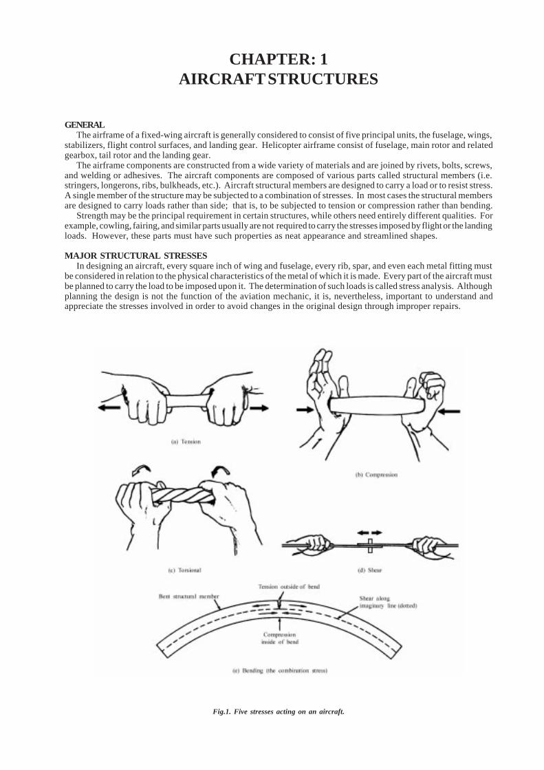
Fig.1. Five stresses acting on an aircraft.
2 L.N.V.M. Society Group of Institutes, Palam Extn., Part-1, Sec-7, Dwarka, New Delhi-77
There are five major stresses to which all aircraft are subjected .(i) Tension (ii) Compression (iii) Torsion (iv) Shear (v) Bending.The term “stress” is often used interchangeably with the word “strain.” Stress is an internal force of a substance
which opposes or resists deformation. Strain is the deformation of a material or substance. Stress, the internal force,can cause strain.
Tension in Fig. (1a) is the stress that resists a force that tends to pull apart. The engine pulls the aircraft forward,but air resistance tries to hold it back. The result is tension, which tries to stretch the aircraft. The tensile strengthof a material is measured in p.s.i. (pounds per square inch) and is calculated by dividing the load (in pounds) requiredto pull the material apart by its cross-sectional area (in square inches).
Compression (1b) is the stress that resists a crushing force. The compressive strength of a material is also measuredin p.s.i. Compression is the stress that tends to shorten or squeeze aircraft parts.
Torsion is the stress that produces twisting. While moving the aircraft forward, the engine also tends to twist itto one side, but other aircraft components hold it on course. Thus, torsion is created. The torsional strength of a materialis its resistance to twisting or torque. (Fig.1c)
Shear is the stress that resists the force tending to cause one layer of a material to slide over an adjacent layer. Tworiveted plates in tension subject the rivets to a shearing force. Usually, the shearing strength of a material is either equalto or less than its tensile or compressive strength. Aircraft parts, especially screws, bolts, and rivets, are often subjectto a shearing force. (Fig.1d).
Bending stress is a combination of compression and tension. The rod in (Fig.1e) has been shortened (compressed)inside of the bend and stretched on the outside of the bend.
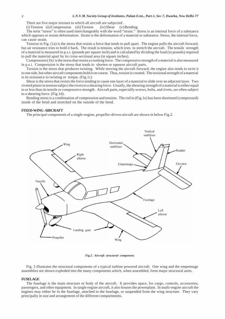
FIXED-WING AIRCRAFTThe principal components of a single-engine, propeller-driven aircraft are shown in below Fig.2.
Fig.2. Aircraft structural component.
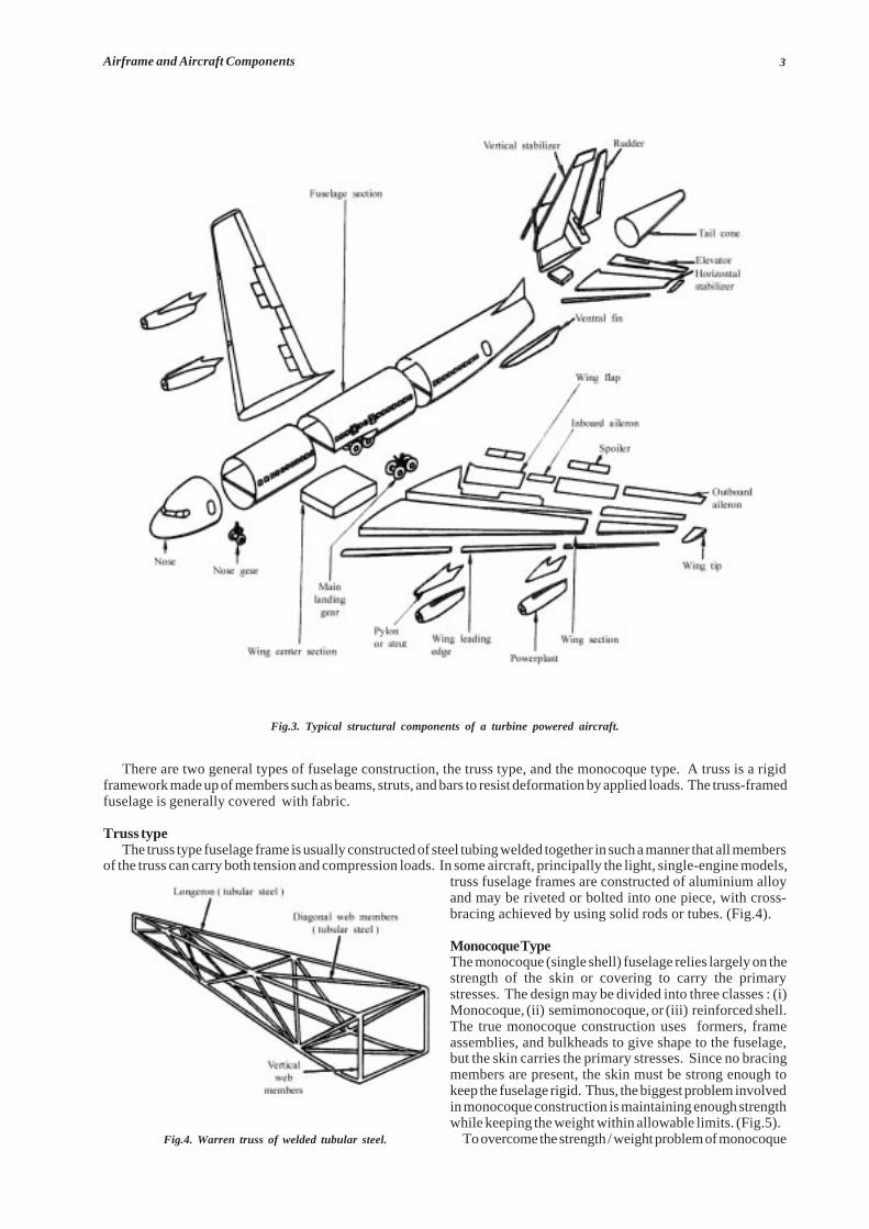
Fig. 3 illustrates the structural components of a typical turbine powered aircraft. One wing and the empennageassemblies are shown exploded into the many components which, when assembled, form major structural units.
FUSELAGEThe fuselage is the main structure or body of the aircraft. It provides space, for cargo, controls, accessories,
passengers, and other equipment. In single engine aircraft, it also houses the powerplant. In multi-engine aircraft theengines may either be in the fuselage, attached to the fuselage, or suspended from the wing structure. They varyprincipally in size and arrangement of the different compartments.
3Airframe and Aircraft Components
Fig.3. Typical structural components of a turbine powered aircraft.
There are two general types of fuselage construction, the truss type, and the monocoque type. A truss is a rigidframework made up of members such as beams, struts, and bars to resist deformation by applied loads. The truss-framedfuselage is generally covered with fabric.
Truss typeThe truss type fuselage frame is usually constructed of steel tubing welded together in such a manner that all members
of the truss can carry both tension and compression loads. In some aircraft, principally the light, single-engine models,truss fuselage frames are constructed of aluminium alloyand may be riveted or bolted into one piece, with cross-bracing achieved by using solid rods or tubes. (Fig.4).
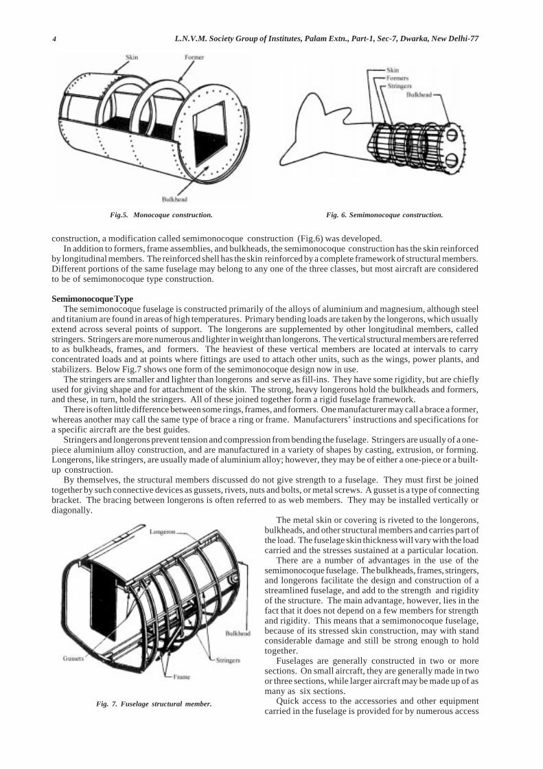
Monocoque TypeThe monocoque (single shell) fuselage relies largely on thestrength of the skin or covering to carry the primarystresses. The design may be divided into three classes : (i)Monocoque, (ii) semimonocoque, or (iii) reinforced shell.The true monocoque construction uses formers, frameassemblies, and bulkheads to give shape to the fuselage,but the skin carries the primary stresses. Since no bracingmembers are present, the skin must be strong enough tokeep the fuselage rigid. Thus, the biggest problem involvedin monocoque construction is maintaining enough strengthwhile keeping the weight within allowable limits. (Fig.5).
To overcome the strength / weight problem of monocoqueFig.4. Warren truss of welded tubular steel.
4 L.N.V.M. Society Group of Institutes, Palam Extn., Part-1, Sec-7, Dwarka, New Delhi-77
construction, a modification called semimonocoque construction (Fig.6) was developed.In addition to formers, frame assemblies, and bulkheads, the semimonocoque construction has the skin reinforced
by longitudinal members. The reinforced shell has the skin reinforced by a complete framework of structural members.Different portions of the same fuselage may belong to any one of the three classes, but most aircraft are consideredto be of semimonocoque type construction.
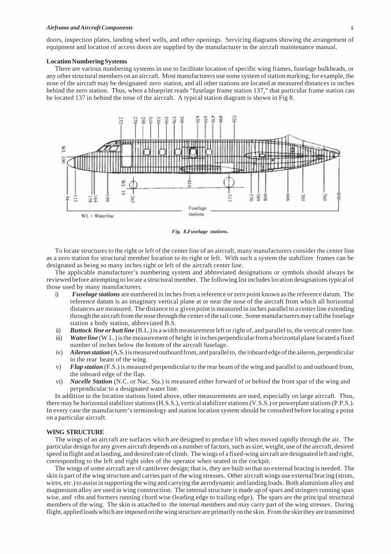
Semimonocoque TypeThe semimonocoque fuselage is constructed primarily of the alloys of aluminium and magnesium, although steel
and titanium are found in areas of high temperatures. Primary bending loads are taken by the longerons, which usuallyextend across several points of support. The longerons are supplemented by other longitudinal members, calledstringers. Stringers are more numerous and lighter in weight than longerons. The vertical structural members are referredto as bulkheads, frames, and formers. The heaviest of these vertical members are located at intervals to carryconcentrated loads and at points where fittings are used to attach other units, such as the wings, power plants, andstabilizers. Below Fig.7 shows one form of the semimonocoque design now in use.
The stringers are smaller and lighter than longerons and serve as fill-ins. They have some rigidity, but are chieflyused for giving shape and for attachment of the skin. The strong, heavy longerons hold the bulkheads and formers,and these, in turn, hold the stringers. All of these joined together form a rigid fuselage framework.
There is often little difference between some rings, frames, and formers. One manufacturer may call a brace a former,whereas another may call the same type of brace a ring or frame. Manufacturers’ instructions and specifications fora specific aircraft are the best guides.
Stringers and longerons prevent tension and compression from bending the fuselage. Stringers are usually of a one-piece aluminium alloy construction, and are manufactured in a variety of shapes by casting, extrusion, or forming.Longerons, like stringers, are usually made of aluminium alloy; however, they may be of either a one-piece or a built-up construction.
By themselves, the structural members discussed do not give strength to a fuselage. They must first be joinedtogether by such connective devices as gussets, rivets, nuts and bolts, or metal screws. A gusset is a type of connectingbracket. The bracing between longerons is often referred to as web members. They may be installed vertically ordiagonally.
The metal skin or covering is riveted to the longerons,bulkheads, and other structural members and carries part ofthe load. The fuselage skin thickness will vary with the loadcarried and the stresses sustained at a particular location.
There are a number of advantages in the use of thesemimonocoque fuselage. The bulkheads, frames, stringers,and longerons facilitate the design and construction of astreamlined fuselage, and add to the strength and rigidityof the structure. The main advantage, however, lies in thefact that it does not depend on a few members for strengthand rigidity. This means that a semimonocoque fuselage,because of its stressed skin construction, may with standconsiderable damage and still be strong enough to holdtogether.
Fuselages are generally constructed in two or moresections. On small aircraft, they are generally made in twoor three sections, while larger aircraft may be made up of asmany as six sections.
Quick access to the accessories and other equipmentcarried in the fuselage is provided for by numerous access
Fig.5. Monocoque construction. Fig. 6. Semimonocoque construction.
Fig. 7. Fuselage structural member.
5Airframe and Aircraft Components
doors, inspection plates, landing wheel wells, and other openings. Servicing diagrams showing the arrangement ofequipment and location of access doors are supplied by the manufacturer in the aircraft maintenance manual.
Location Numbering SystemsThere are various numbering systems in use to facilitate location of specific wing frames, fuselage bulkheads, or
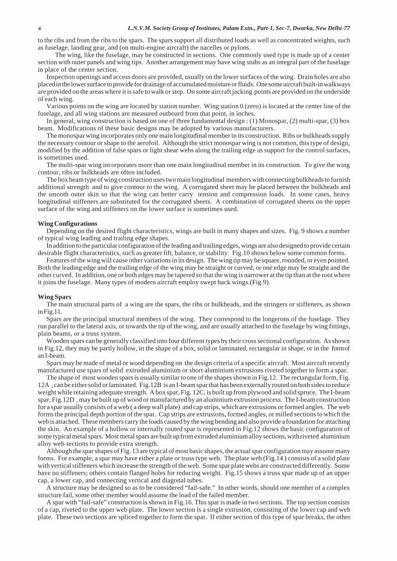
any other structural members on an aircraft. Most manufacturers use some system of station marking; for example, thenose of the aircraft may be designated zero station, and all other stations are located at measured distances in inchesbehind the zero station. Thus, when a blueprint reads “fuselage frame station 137,” that particular frame station canbe located 137 in behind the nose of the aircraft. A typical station diagram is shown in Fig 8.
Fig. 8.Fuselage stations.
To locate structures to the right or left of the center line of an aircraft, many manufacturers consider the center lineas a zero station for structural member location to its right or left. With such a system the stabilizer frames can bedesignated as being so many inches right or left of the aircraft center line.
The applicable manufacturer’s numbering system and abbreviated designations or symbols should always bereviewed before attempting to locate a structural member. The following list includes location designations typical ofthose used by many manufacturers.
i) Fuselage stations are numbered in inches from a reference or zero point known as the reference datum. Thereference datum is an imaginary vertical plane at or near the nose of the aircraft from which all horizontaldistances are measured. The distance to a given point is measured in inches parallel to a center line extendingthrough the aircraft from the nose through the center of the tail cone. Some manufacturers may call the fuselagestation a body station, abbreviated B.S.
ii) Buttock line or butt line (B.L.) is a width measurement left or right of, and parallel to, the vertical center line.iii) Water line (W.L.) is the measurement of height in inches perpendicular from a horizontal plane located a fixed
number of inches below the bottom of the aircraft fuselage.iv) Aileron station (A.S.) is measured outboard from, and parallel to, the inboard edge of the aileron, perpendicular
to the rear beam of the wing.v) Flap station (F.S.) is measured perpendicular to the rear beam of the wing and parallel to and outboard from,
the inboard edge of the flap.vi) Nacelle Station (N.C. or Nac. Sta.) is measured either forward of or behind the front spar of the wing and
perpendicular to a designated water line.In addition to the location stations listed above, other measurements are used, especially on large aircraft. Thus,
there may be horizontal stabilizer stations (H.S.S.), vertical stabilizer stations (V.S.S.) or powerplant stations (P.P.S.).In every case the manufacturer’s terminology and station location system should be consulted before locating a pointon a particular aircraft.
WING STRUCTUREThe wings of an aircraft are surfaces which are designed to produce lift when moved rapidly through the air. The
particular design for any given aircraft depends on a number of factors, such as size, weight, use of the aircraft, desiredspeed in flight and at landing, and desired rate of climb. The wings of a fixed-wing aircraft are designated left and right,corresponding to the left and right sides of the operator when seated in the cockpit.
The wings of some aircraft are of cantilever design; that is, they are built so that no external bracing is needed. Theskin is part of the wing structure and carries part of the wing stresses. Other aircraft wings use external bracing (struts,wires, etc.) to assist in supporting the wing and carrying the aerodynamic and landing loads. Both aluminium alloy andmagnesium alloy are used in wing construction. The internal structure is made up of spars and stringers running spanwise, and ribs and formers running chord wise (leading edge to trailing edge). The spars are the principal structuralmembers of the wing. The skin is attached to the internal members and may carry part of the wing stresses. Duringflight, applied loads which are imposed on the wing structure are primarily on the skin. From the skin they are transmitted
6 L.N.V.M. Society Group of Institutes, Palam Extn., Part-1, Sec-7, Dwarka, New Delhi-77
to the ribs and from the ribs to the spars. The spars support all distributed loads as well as concentrated weights, suchas fuselage, landing gear, and (on multi-engine aircraft) the nacelles or pylons.
The wing, like the fuselage, may be constructed in sections. One commonly used type is made up of a centersection with outer panels and wing tips. Another arrangement may have wing stubs as an integral part of the fuselagein place of the center section.
Inspection openings and access doors are provided, usually on the lower surfaces of the wing. Drain holes are alsoplaced in the lower surface to provide for drainage of accumulated moisture or fluids. One some aircraft built-in walkwaysare provided on the areas where it is safe to walk or step. On some aircraft jacking points are provided on the undersideof each wing.
Various points on the wing are located by station number. Wing station 0 (zero) is located at the center line of thefuselage, and all wing stations are measured outboard from that point, in inches.
In general, wing construction is based on one of three fundamental design : (1) Monospar, (2) multi-spar, (3) boxbeam. Modifications of these basic designs may be adopted by various manufacturers.
The monospar wing incorporates only one main longitudinal member in its construction. Ribs or bulkheads supplythe necessary contour or shape to the aerofoil. Although the strict monospar wing is not common, this type of design,modified by the addition of false spars or light shear webs along the trailing edge as support for the control surfaces,is sometimes used.
The multi-spar wing incorporates more than one main longitudinal member in its construction. To give the wingcontour, ribs or bulkheads are often included.
The box beam type of wing construction uses two main longitudinal members with connecting bulkheads to furnishadditional strength and to give contour to the wing. A corrugated sheet may be placed between the bulkheads andthe smooth outer skin so that the wing can better carry tension and compression loads. In some cases, heavylongitudinal stiffeners are substituted for the corrugated sheets. A combination of corrugated sheets on the uppersurface of the wing and stiffeners on the lower surface is sometimes used.
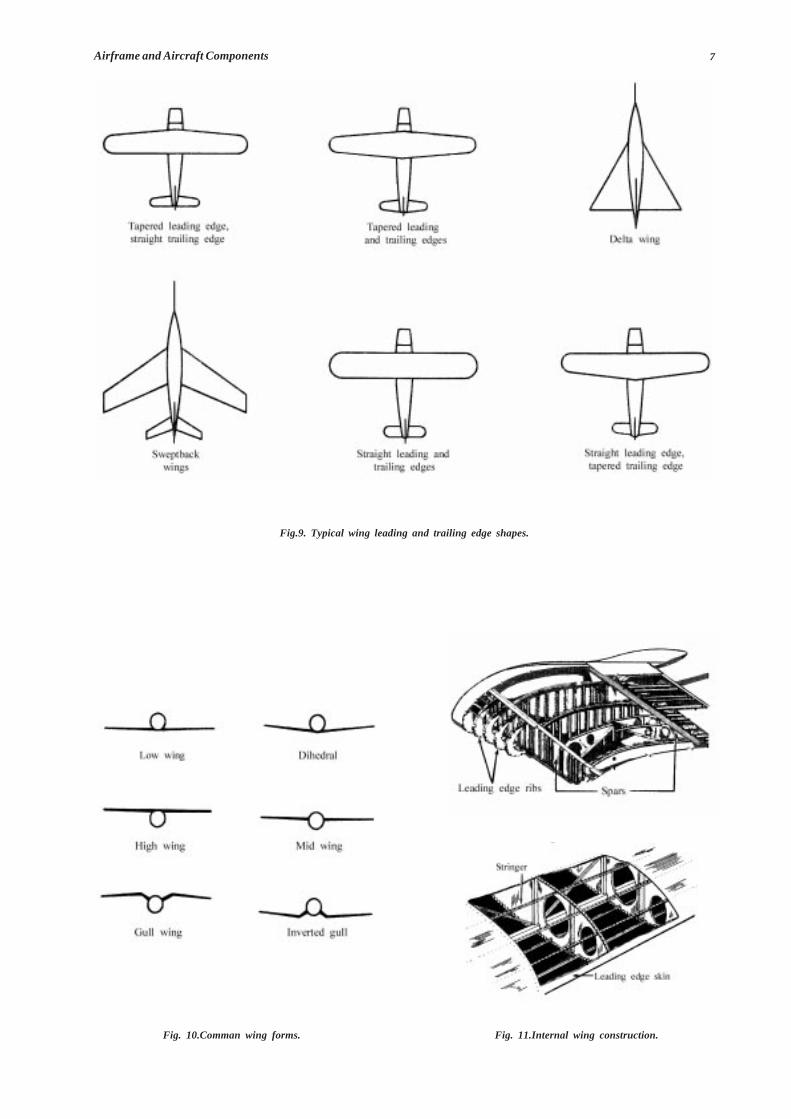
Wing ConfigurationsDepending on the desired flight characteristics, wings are built in many shapes and sizes. Fig. 9 shows a number
of typical wing leading and trailing edge shapes.In addition to the particular configuration of the leading and trailing edges, wings are also designed to provide certain
desirable flight characteristics, such as greater lift, balance, or stability. Fig.10 shows below some common forms.Features of the wing will cause other variations in its design. The wing tip may be square, rounded, or even pointed.
Both the leading edge and the trailing edge of the wing may be straight or curved, or one edge may be straight and theother curved. In addition, one or both edges may be tapered so that the wing is narrower at the tip than at the root whereit joins the fuselage. Many types of modern aircraft employ swept back wings.(Fig.9).
Wing SparsThe main structural parts of a wing are the spars, the ribs or bulkheads, and the stringers or stiffeners, as shown
in Fig.11.Spars are the principal structural members of the wing. They correspond to the longerons of the fuselage. They
run parallel to the lateral axis, or towards the tip of the wing, and are usually attached to the fuselage by wing fittings,plain beams, or a truss system.
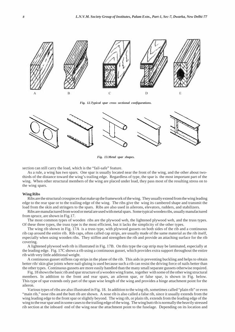
Wooden spars can be generally classified into four different types by their cross sectional configuration. As shownin Fig.12, they may be partly hollow, in the shape of a box, solid or laminated, rectangular in shape, or in theform ofan I-beam.
Spars may be made of metal or wood depending on the design criteria of a specific aircraft. Most aircraft recentlymanufactured use spars of solid extruded aluminium or short aluminium extrusions riveted together to form a spar.
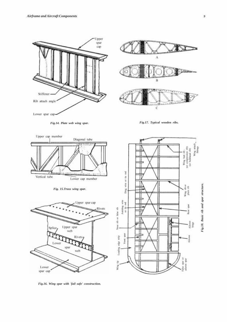
The shape of most wooden spars is usually similar to one of the shapes shown in Fig.12. The rectangular form, Fig.12A , can be either solid or laminated. Fig.12B is an I-beam spar that has been externally routed on both sides to reduceweight while retaining adequate strength. A box spar, Fig. 12C, is built up from plywood and solid spruce. The I-beamspar, Fig.12D , may be built up of wood or manufactured by an aluminium extrusion process. The I-beam constructionfor a spar usually consists of a web ( a deep wall plate) and cap strips, which are extrusions or formed angles. The webforms the principal depth portion of the spar. Cap strips are extrusions, formed angles, or milled sections to which theweb is attached. These members carry the loads caused by the wing bending and also provide a foundation for attachingthe skin. An example of a hollow or internally routed spar is represented in Fig.12 shows the basic configuration ofsome typical metal spars. Most metal spars are built up from extruded aluminium alloy sections, with riveted aluminiumalloy web sections to provide extra strength.
Although the spar shapes of Fig. 13 are typical of most basic shapes, the actual spar configuration may assume manyforms. For example, a spar may have either a plate or truss type web. The plate web (Fig.14 ) consists of a solid platewith vertical stiffeners which increase the strength of the web. Some spar plate webs are constructed differently. Somehave no stiffeners; others contain flanged holes for reducing weight. Fig.15 shows a truss spar made up of an uppercap, a lower cap, and connecting vertical and diagonal tubes.
A structure may be designed so as to be considered “fail-safe.” In other words, should one member of a complexstructure fail, some other member would assume the load of the failed member.
A spar with “fail-safe” construction is shown in Fig.16. This spar is made in two sections. The top section consistsof a cap, riveted to the upper web plate. The lower section is a single extrusion, consisting of the lower cap and webplate. These two sections are spliced together to form the spar. If either section of this type of spar breaks, the other
7Airframe and Aircraft Components
Fig.9. Typical wing leading and trailing edge shapes.
Fig. 10.Comman wing forms. Fig. 11.Internal wing construction.
8 L.N.V.M. Society Group of Institutes, Palam Extn., Part-1, Sec-7, Dwarka, New Delhi-77
section can still carry the load, which is the “fail-safe” feature.As a rule, a wing has two spars. One spar is usually located near the front of the wing, and the other about two-
thirds of the distance toward the wing’s trailing edge. Regardless of type, the spar is the most important part of thewing. When other structural members of the wing are placed under load, they pass most of the resulting stress on tothe wing spars.
Wing RibsRibs are the structural crosspieces that make up the framework of the wing. They usually extend from the wing leading
edge to the rear spar or to the trailing edge of the wing. The ribs give the wing its cambered shape and transmit theload from the skin and stringers to the spars. Ribs are also used in ailerons, elevators, rudders, and stabilizers.
Ribs are manufactured from wood or metal are used with metal spars. Some typical wooden ribs, usually manufacturedfrom spruce, are shown in Fig.17.
The most common types of wooden ribs are the plywood web, the lightened plywood web, and the truss types.Of these three types, the truss type is the most efficient, but it lacks the simplicity of the other types.
The wing rib shown in Fig. 17A is a truss type, with plywood gussets on both sides of the rib and a continuousrib cap around the entire rib. Rib caps, often called cap strips, are usually made of the same material as the rib itself,especially when using wooden ribs. They stiffen and strengthen the rib and provide an attaching surface for the ribcovering.
A lightened plywood web rib is illustrated in Fig. 17B. On this type the cap strip may be laminated, especially atthe leading edge. Fig. 17C shows a rib using a continuous gusset, which provides extra support throughout the entirerib with very little additional weight.
A continuous gusset stiffens cap strips in the plane of the rib. This aids in preventing buckling and helps to obtainbetter rib/ skin glue joints where nail-gluing is used because such a rib can resist the driving force of nails better thanthe other types. Continuous gussets are more easily handled than the many small separate gussets otherwise required.
Fig. 18 shows the basic rib and spar structure of a wooden wing frame, together with some of the other wing structuralmembers. In addition to the front and rear spars, an aileron spar, or false spar, is shown in Fig. below.This type of spar extends only part of the span wise length of the wing and provides a hinge attachment point for theaileron.
Various types of ribs are also illustrated in Fig. 18. In addition to the wing rib, sometimes called “plain rib” or even“main rib,” nose ribs and the butt rib are shown. A nose rib is also called a false rib, since it usually extends from thewing leading edge to the front spar or slightly beyond. The wing rib, or plain rib, extends from the leading edge of thewing to the rear spar and in some cases to the trailing edge of the wing. The wing butt rib is normally the heavily stressedrib section at the inboard end of the wing near the attachment point to the fuselage. Depending on its location and
Fig. 12.Typical spar cross sectional configurations.
Fig. 13.Metal spar shapes.
9Airframe and Aircraft Components
Fig.14. Plate web wing spar.
Fig. 15.Truss wing spar.
Fig.16. Wing spar with 'fail safe' construction.
Fig.17. Typical wooden ribs.
Fig
.18.
Bas
ic r
ib a
nd s
par
stru
ctur
e.
10 L.N.V.M. Society Group of Institutes, Palam Extn., Part-1, Sec-7, Dwarka, New Delhi-77
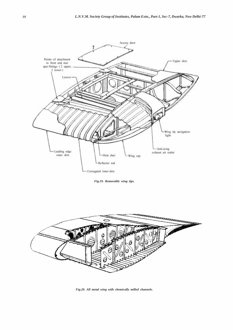
Fig.19. Removable wing tips.
Fig.20. All metal wing with chemically milled channels.
11Airframe and Aircraft Components
method of attachment, a butt rib may be called a bulkhead rib or a compression rib, if it is designed to receive compressionloads that tend to force the wing spars together.
Since the ribs are laterally weak, they are strengthened in some wings by tapes that woven above and below ribsections to prevent side wise bending of the ribs.
Drag and anti drag wires (Fig. 18) are crisscrossed between the spars to form a truss to resist forces acting on thewing in the direction of the wing chord. These tension wires are also referred to as tie rods. The wire designed to resistthe back as tie rods. The wire designed to resist the backward forces is called a drag wire; the anti drag wire resiststhe forward forces in the chord direction.
The wing attachment fittings, shown in Fig. 18, provide a means of attaching the wing to the aircraft fuselage.The wing tip is often a removable unit, bolted to the outboard end of the wing panel. One reason for this is the
vulnerability of the wing tips to damage, especially during ground handling and taxiing.Fig. 19 shows a removable wing tip for a large aircraft wing. The wing-tip assembly is of aluminium alloy construction.
The wing-tip cap is secured to the tip with countersunk screws and is secured to the inter spar structure at four pointswith 1/4 in bolts. The tip leading edge contains the best anti-icing duct. Wing-heated air is exhausted through a louveron the top surface of the tip. Wing position lights are located at the center of the tip and are not directly visible fromthe cockpit. As an indication that the wing tip light is operating, some wing tips are equipped with a lucid rod to transitthe light to the leading edge.
Fig. 20 shows a cross sectional view of an all metal full cantilever (no external bracing) wing section. The wing ismade up of spars, ribs, and lower and upper wing skin covering. With few exceptions, wings of this type are of thestressed skin design ( the skin is part of the wing structure and carries part of the wing stresses).
The top and bottom wing skin covers are made up of several integrally stiffened sections. This type of wingconstruction permits the installation of bladder-type fuel cells in the wings or is sealed to hold fuel without the usualfuel cells or tanks. A wing which is constructed to allow it to be used as a fuel cell or tank is referred to as a “wet-wing”.
A wing that uses a box-beam design is shown in Fig. 21. This type of construction not only increases strength andreduces weight, but it also enables the wing to serve as a fuel tank when properly sealed.
Both aluminium honeycomb and fiber glass honeycomb sandwich material are commonly used in the constructionof wing and stabilizer surfaces, bulkheads, floors, control surfaces, and trim tabs. Aluminium honeycomb material ismade of aluminium foil honeycomb core, bonded between sheets of aluminium. Fibre glass honeycomb material consistsof fibre glass honeycomb core bonded between layers of fibre glass cloth.
In the construction of large aircraft structures, and in some small aircraft as well, the honeycomb sandwich structureemployes either aluminium or reinforced plastic materials. Honeycomb panels are usually a lightweight cellular coresandwiched between two thin skins or facing materials such as aluminium, wood, or plastic.
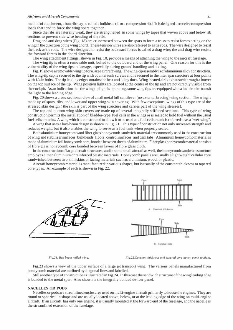
Aircraft honeycomb material is manufactured in various shapes, but is usually of the constant thickness or taperedcore types. An example of each is shown in Fig. 22.
Fig.21. Box beam milled wing. Fig.22.Constant thickness and tapered core honey comb sections.
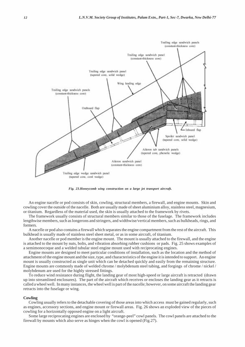
Fig.23 shows a view of the upper surface of a large jet transport wing. The various panels manufactured fromhoneycomb material are outlined by diagonal lines and labelled.
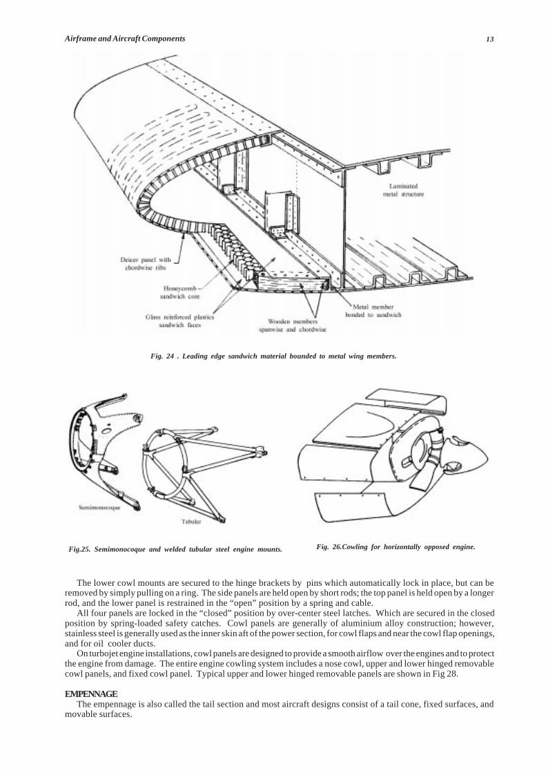
Still another type of construction is illustrated in Fig.24. In this case the sandwich structure of the wing leading edgeis bonded to the metal spar. Also shown is the integrally bonded de-icer panel.
NACELLES OR PODSNacelles or pods are streamlined enclosures used on multi-engine aircraft primarily to house the engines. They are
round or spherical in shape and are usually located above, below, or at the leading edge of the wing on multi-engineaircraft. If an aircraft has only one engine, it is usually mounted at the forward end of the fuselage, and the nacelle isthe streamlined extension of the fuselage.
12 L.N.V.M. Society Group of Institutes, Palam Extn., Part-1, Sec-7, Dwarka, New Delhi-77
An engine nacelle or pod consists of skin, cowling, structural members, a firewall, and engine mounts. Skin andcowling cover the outside of the nacelle. Both are usually made of sheet aluminium alloy, stainless steel, magnesium,or titanium. Regardless of the material used, the skin is usually attached to the framework by rivets.
The framework usually consists of structural members similar to those of the fuselage. The framework includeslengthwise members, such as longerons and stringers, and widthwise/vertical members, such as bulkheads, rings, andformers.
A nacelle or pod also contains a firewall which separates the engine compartment from the rest of the aircraft. Thisbulkhead is usually made of stainless steel sheet metal, or as in some aircraft, of titanium.
Another nacelle or pod member is the engine mount. The mount is usually attached to the firewall, and the engineis attached to the mount by nuts, bolts, and vibration absorbing rubber cushions or pads. Fig. 25 shows examples ofa semimonocoque and a welded tubular steel engine mount used with reciprocating engines.
Engine mounts are designed to meet particular conditions of installation, such as the location and the method ofattachment of the engine mount and the size, type, and characteristics of the engine it is intended to support. An enginemount is usually constructed as single unit which can be detached quickly and easily from the remaining structure.Engine mounts are commonly made of welded chrome / molybdenum steel tubing, and forgings of chrome / nickel /molybdenum are used for the highly stressed fittings.
To reduce wind resistance during flight, the landing gear of most high-speed or large aircraft is retracted (drawnup into streamlined enclosures). The part of the aircraft which receives or encloses the landing gear as it retracts iscalled a wheel well. In many instances, the wheel well is part of the nacelle; however, on some aircraft the landing gearretracts into the fuselage or wing.
CowlingCowling usually refers to the detachable covering of those areas into which access must be gained regularly, such
as engines, accessory sections, and engine mount or firewall areas. Fig. 26 shows an exploded view of the pieces ofcowling for a horizontally opposed engine on a light aircraft.
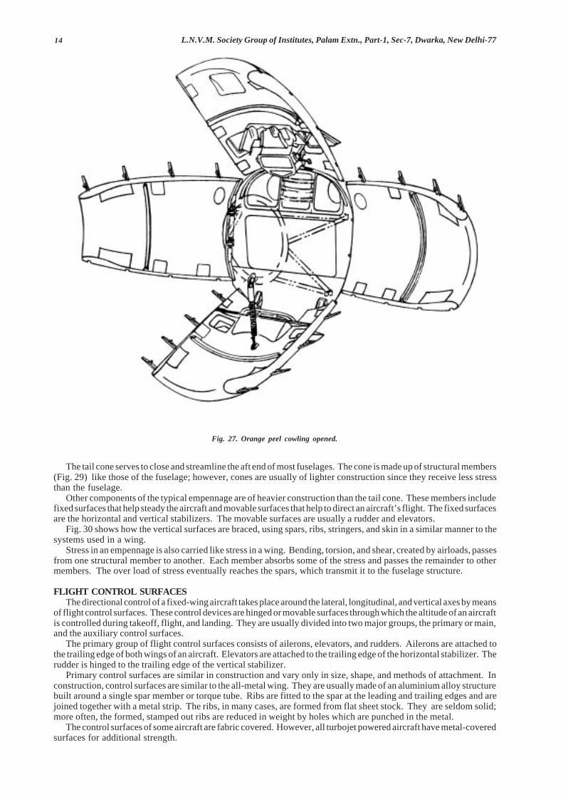
Some large reciprocating engines are enclosed by “orange-peel” cowl panels. The cowl panels are attached to thefirewall by mounts which also serve as hinges when the cowl is opened (Fig.27).
Fig. 23.Honeycomb wing construction on a large jet transport aircraft.
13Airframe and Aircraft Components
The lower cowl mounts are secured to the hinge brackets by pins which automatically lock in place, but can beremoved by simply pulling on a ring. The side panels are held open by short rods; the top panel is held open by a longerrod, and the lower panel is restrained in the “open” position by a spring and cable.
All four panels are locked in the “closed” position by over-center steel latches. Which are secured in the closedposition by spring-loaded safety catches. Cowl panels are generally of aluminium alloy construction; however,stainless steel is generally used as the inner skin aft of the power section, for cowl flaps and near the cowl flap openings,and for oil cooler ducts.
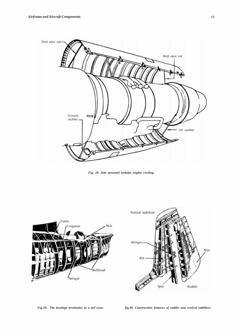
On turbojet engine installations, cowl panels are designed to provide a smooth airflow over the engines and to protectthe engine from damage. The entire engine cowling system includes a nose cowl, upper and lower hinged removablecowl panels, and fixed cowl panel. Typical upper and lower hinged removable panels are shown in Fig 28.
EMPENNAGEThe empennage is also called the tail section and most aircraft designs consist of a tail cone, fixed surfaces, and
movable surfaces.
Fig. 24 . Leading edge sandwich material bounded to metal wing members.
Fig.25. Semimonocoque and welded tubular steel engine mounts. Fig. 26.Cowling for horizontally opposed engine.
14 L.N.V.M. Society Group of Institutes, Palam Extn., Part-1, Sec-7, Dwarka, New Delhi-77
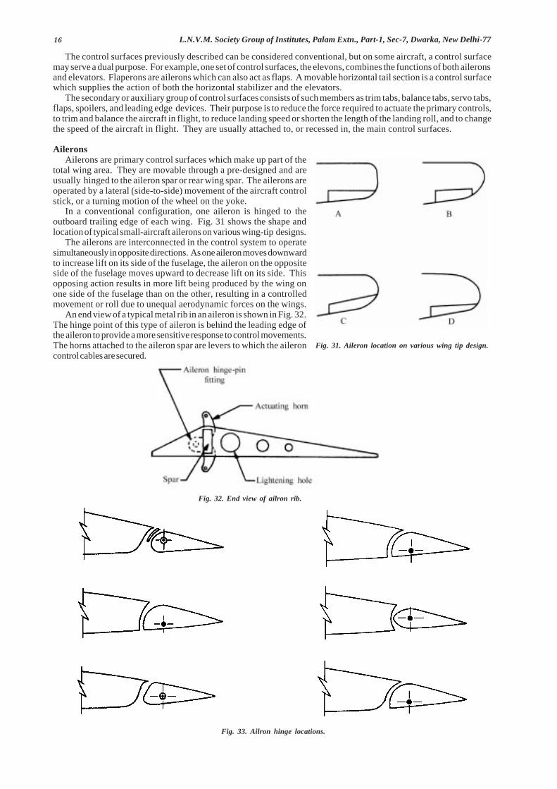
The tail cone serves to close and streamline the aft end of most fuselages. The cone is made up of structural members(Fig. 29) like those of the fuselage; however, cones are usually of lighter construction since they receive less stressthan the fuselage.
Other components of the typical empennage are of heavier construction than the tail cone. These members includefixed surfaces that help steady the aircraft and movable surfaces that help to direct an aircraft’s flight. The fixed surfacesare the horizontal and vertical stabilizers. The movable surfaces are usually a rudder and elevators.
Fig. 30 shows how the vertical surfaces are braced, using spars, ribs, stringers, and skin in a similar manner to thesystems used in a wing.
Stress in an empennage is also carried like stress in a wing. Bending, torsion, and shear, created by airloads, passesfrom one structural member to another. Each member absorbs some of the stress and passes the remainder to othermembers. The over load of stress eventually reaches the spars, which transmit it to the fuselage structure.
FLIGHT CONTROL SURFACESThe directional control of a fixed-wing aircraft takes place around the lateral, longitudinal, and vertical axes by means
of flight control surfaces. These control devices are hinged or movable surfaces through which the altitude of an aircraftis controlled during takeoff, flight, and landing. They are usually divided into two major groups, the primary or main,and the auxiliary control surfaces.
The primary group of flight control surfaces consists of ailerons, elevators, and rudders. Ailerons are attached tothe trailing edge of both wings of an aircraft. Elevators are attached to the trailing edge of the horizontal stabilizer. Therudder is hinged to the trailing edge of the vertical stabilizer.
Primary control surfaces are similar in construction and vary only in size, shape, and methods of attachment. Inconstruction, control surfaces are similar to the all-metal wing. They are usually made of an aluminium alloy structurebuilt around a single spar member or torque tube. Ribs are fitted to the spar at the leading and trailing edges and arejoined together with a metal strip. The ribs, in many cases, are formed from flat sheet stock. They are seldom solid;more often, the formed, stamped out ribs are reduced in weight by holes which are punched in the metal.
The control surfaces of some aircraft are fabric covered. However, all turbojet powered aircraft have metal-coveredsurfaces for additional strength.
Fig. 27. Orange peel cowling opened.
15Airframe and Aircraft Components
Fig. 28. Side mounted turbojet engine cowling.
Fig.29. The fuselage terminates in a tail cone. fig.30. Construction features of rudder and vertical stabilizer.
16 L.N.V.M. Society Group of Institutes, Palam Extn., Part-1, Sec-7, Dwarka, New Delhi-77
Fig. 32. End view of ailron rib.
Fig. 33. Ailron hinge locations.
The control surfaces previously described can be considered conventional, but on some aircraft, a control surfacemay serve a dual purpose. For example, one set of control surfaces, the elevons, combines the functions of both aileronsand elevators. Flaperons are ailerons which can also act as flaps. A movable horizontal tail section is a control surfacewhich supplies the action of both the horizontal stabilizer and the elevators.
The secondary or auxiliary group of control surfaces consists of such members as trim tabs, balance tabs, servo tabs,flaps, spoilers, and leading edge devices. Their purpose is to reduce the force required to actuate the primary controls,to trim and balance the aircraft in flight, to reduce landing speed or shorten the length of the landing roll, and to changethe speed of the aircraft in flight. They are usually attached to, or recessed in, the main control surfaces.
AileronsAilerons are primary control surfaces which make up part of the
total wing area. They are movable through a pre-designed and areusually hinged to the aileron spar or rear wing spar. The ailerons areoperated by a lateral (side-to-side) movement of the aircraft controlstick, or a turning motion of the wheel on the yoke.
In a conventional configuration, one aileron is hinged to theoutboard trailing edge of each wing. Fig. 31 shows the shape andlocation of typical small-aircraft ailerons on various wing-tip designs.
The ailerons are interconnected in the control system to operatesimultaneously in opposite directions. As one aileron moves downwardto increase lift on its side of the fuselage, the aileron on the oppositeside of the fuselage moves upward to decrease lift on its side. Thisopposing action results in more lift being produced by the wing onone side of the fuselage than on the other, resulting in a controlledmovement or roll due to unequal aerodynamic forces on the wings.
An end view of a typical metal rib in an aileron is shown in Fig. 32.The hinge point of this type of aileron is behind the leading edge ofthe aileron to provide a more sensitive response to control movements.The horns attached to the aileron spar are levers to which the aileroncontrol cables are secured.
Fig. 31. Aileron location on various wing tip design.
17Airframe and Aircraft Components
Fig
.34.
Con
trol
sur
face
on
a la
rge
turb
ojet
air
craf
t.
18 L.N.V.M. Society Group of Institutes, Palam Extn., Part-1, Sec-7, Dwarka, New Delhi-77
Large aircraft may use all-metal ailerons, except for fibber glass tailing edges, hinged to the rear wing spar in at leastfour place. Fig. 33 shows several examples of aileron installation.
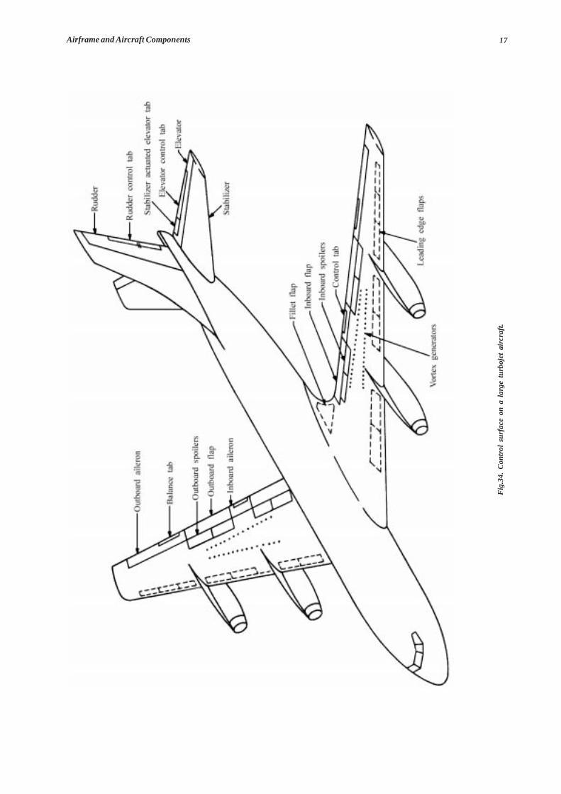
All the control surfaces of a large turbojet aircraft are shown in Fig. 34. As illustrated, each wing has two ailerons,one in the conventional position at the outboard trailing edge of the wing and another hinged to the trailing edge ofthe wing center section.
The complex lateral control system in large turbojet aircraft is far more sophisticated than the type employed in alight aeroplane. During low-speed flight all lateral control surfaces operate to provide maximum stability. This includesall four ailerons, flaps, and spoilers. At high speeds, flaps are retracted and the outboard ailerons are locked out of theaileron control system.
The major part of the skin area of the inboard ailerons is aluminium honeycomb panels. Exposed honeycomb edgesare covered with sealant and protective finish. The aileron nose taper and extends forward of the aileron hinge line.Each inboard aileron is positioned between the inboard and outboard flaps at the trailing edge of the wing. The aileronhinge supports extend aft and are attached to aileron hinge bearings to support the aileron.
The outboard ailerons are made up of a nose spar and ribs covered with aluminium honeycomb panels. A continuoushinge attached to the forward edge of the nose is grooved to mate with the hem of a fabric seal.
The outboard ailerons are located in the trailing edge of each outboard wing section. Hinge supports extend aft fromthe wing and are attached to the aileron hinge bearing to support the aileron. The nose of the aileron extends into abalance chamber in the wing and is attached to balance panels.
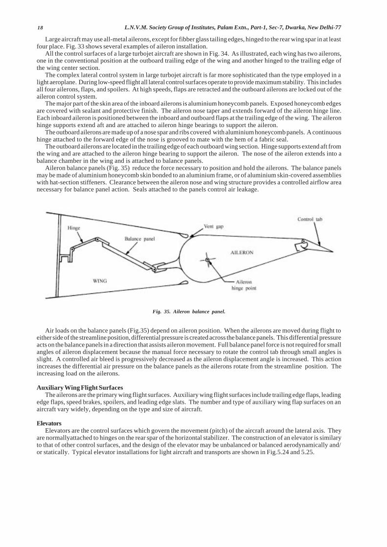
Aileron balance panels (Fig. 35) reduce the force necessary to position and hold the ailerons. The balance panelsmay be made of aluminium honeycomb skin bonded to an aluminium frame, or of aluminium skin-covered assemblieswith hat-section stiffeners. Clearance between the aileron nose and wing structure provides a controlled airflow areanecessary for balance panel action. Seals attached to the panels control air leakage.
Fig. 35. Aileron balance panel.
Air loads on the balance panels (Fig.35) depend on aileron position. When the ailerons are moved during flight toeither side of the streamline position, differential pressure is created across the balance panels. This differential pressureacts on the balance panels in a direction that assists aileron movement. Full balance panel force is not required for smallangles of aileron displacement because the manual force necessary to rotate the control tab through small angles isslight. A controlled air bleed is progressively decreased as the aileron displacement angle is increased. This actionincreases the differential air pressure on the balance panels as the ailerons rotate from the streamline position. Theincreasing load on the ailerons.
Auxiliary Wing Flight SurfacesThe ailerons are the primary wing flight surfaces. Auxiliary wing flight surfaces include trailing edge flaps, leading
edge flaps, speed brakes, spoilers, and leading edge slats. The number and type of auxiliary wing flap surfaces on anaircraft vary widely, depending on the type and size of aircraft.
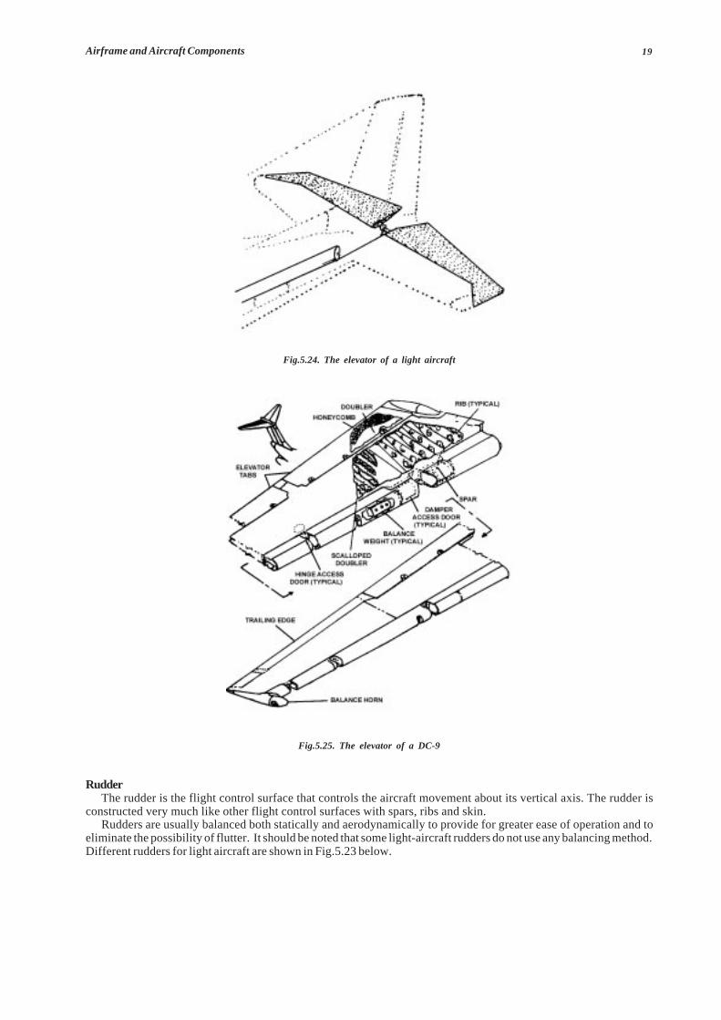
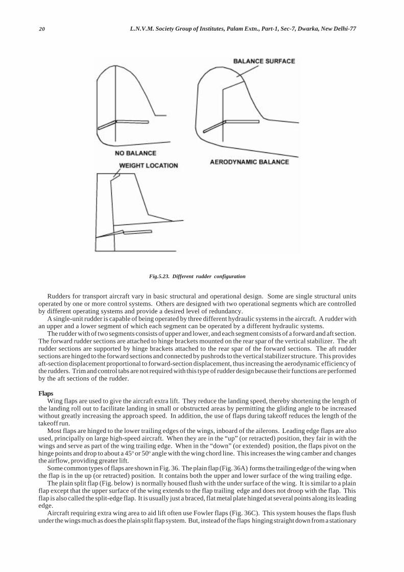
ElevatorsElevators are the control surfaces which govern the movement (pitch) of the aircraft around the lateral axis. They
are normallyattached to hinges on the rear spar of the horizontal stabilizer. The construction of an elevator is similaryto that of other control surfaces, and the design of the elevator may be unbalanced or balanced aerodynamically and/or statically. Typical elevator installations for light aircraft and transports are shown in Fig.5.24 and 5.25.
19Airframe and Aircraft Components
Fig.5.24. The elevator of a light aircraft
Fig.5.25. The elevator of a DC-9
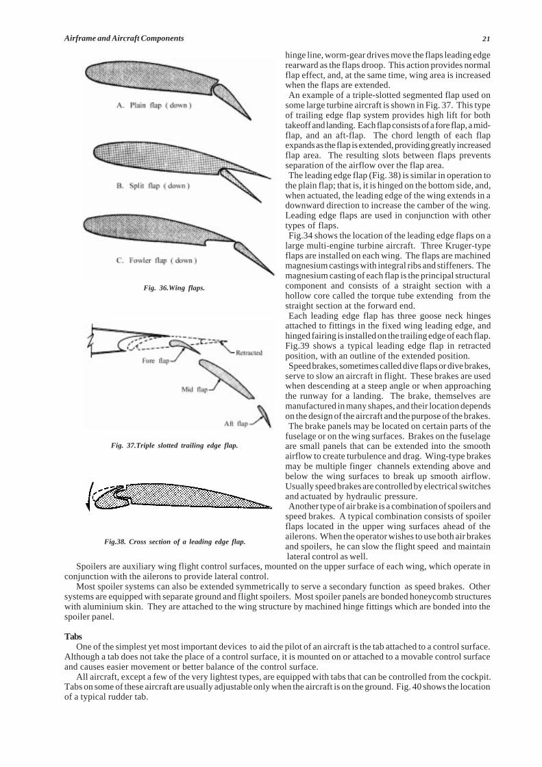
RudderThe rudder is the flight control surface that controls the aircraft movement about its vertical axis. The rudder is
constructed very much like other flight control surfaces with spars, ribs and skin.Rudders are usually balanced both statically and aerodynamically to provide for greater ease of operation and to
eliminate the possibility of flutter. It should be noted that some light-aircraft rudders do not use any balancing method.Different rudders for light aircraft are shown in Fig.5.23 below.
20 L.N.V.M. Society Group of Institutes, Palam Extn., Part-1, Sec-7, Dwarka, New Delhi-77
Fig.5.23. Different rudder configuration
Rudders for transport aircraft vary in basic structural and operational design. Some are single structural unitsoperated by one or more control systems. Others are designed with two operational segments which are controlledby different operating systems and provide a desired level of redundancy.
A single-unit rudder is capable of being operated by three different hydraulic systems in the aircraft. A rudder withan upper and a lower segment of which each segment can be operated by a different hydraulic systems.
The rudder with of two segments consists of upper and lower, and each segment consists of a forward and aft section.The forward rudder sections are attached to hinge brackets mounted on the rear spar of the vertical stabilizer. The aftrudder sections are supported by hinge brackets attached to the rear spar of the forward sections. The aft ruddersections are hinged to the forward sections and connected by pushrods to the vertical stabilizer structure. This providesaft-section displacement proportional to forward-section displacement, thus increasing the aerodynamic efficiency ofthe rudders. Trim and control tabs are not required with this type of rudder design because their functions are performedby the aft sections of the rudder.
FlapsWing flaps are used to give the aircraft extra lift. They reduce the landing speed, thereby shortening the length of
the landing roll out to facilitate landing in small or obstructed areas by permitting the gliding angle to be increasedwithout greatly increasing the approach speed. In addition, the use of flaps during takeoff reduces the length of thetakeoff run.
Most flaps are hinged to the lower trailing edges of the wings, inboard of the ailerons. Leading edge flaps are alsoused, principally on large high-speed aircraft. When they are in the “up” (or retracted) position, they fair in with thewings and serve as part of the wing trailing edge. When in the “down” (or extended) position, the flaps pivot on thehinge points and drop to about a 45o or 50o angle with the wing chord line. This increases the wing camber and changesthe airflow, providing greater lift.
Some common types of flaps are shown in Fig. 36. The plain flap (Fig. 36A) forms the trailing edge of the wing whenthe flap is in the up (or retracted) position. It contains both the upper and lower surface of the wing trailing edge.
The plain split flap (Fig. below) is normally housed flush with the under surface of the wing. It is similar to a plainflap except that the upper surface of the wing extends to the flap trailing edge and does not droop with the flap. Thisflap is also called the split-edge flap. It is usually just a braced, flat metal plate hinged at several points along its leadingedge.
Aircraft requiring extra wing area to aid lift often use Fowler flaps (Fig. 36C). This system houses the flaps flushunder the wings much as does the plain split flap system. But, instead of the flaps hinging straight down from a stationary
21Airframe and Aircraft Components
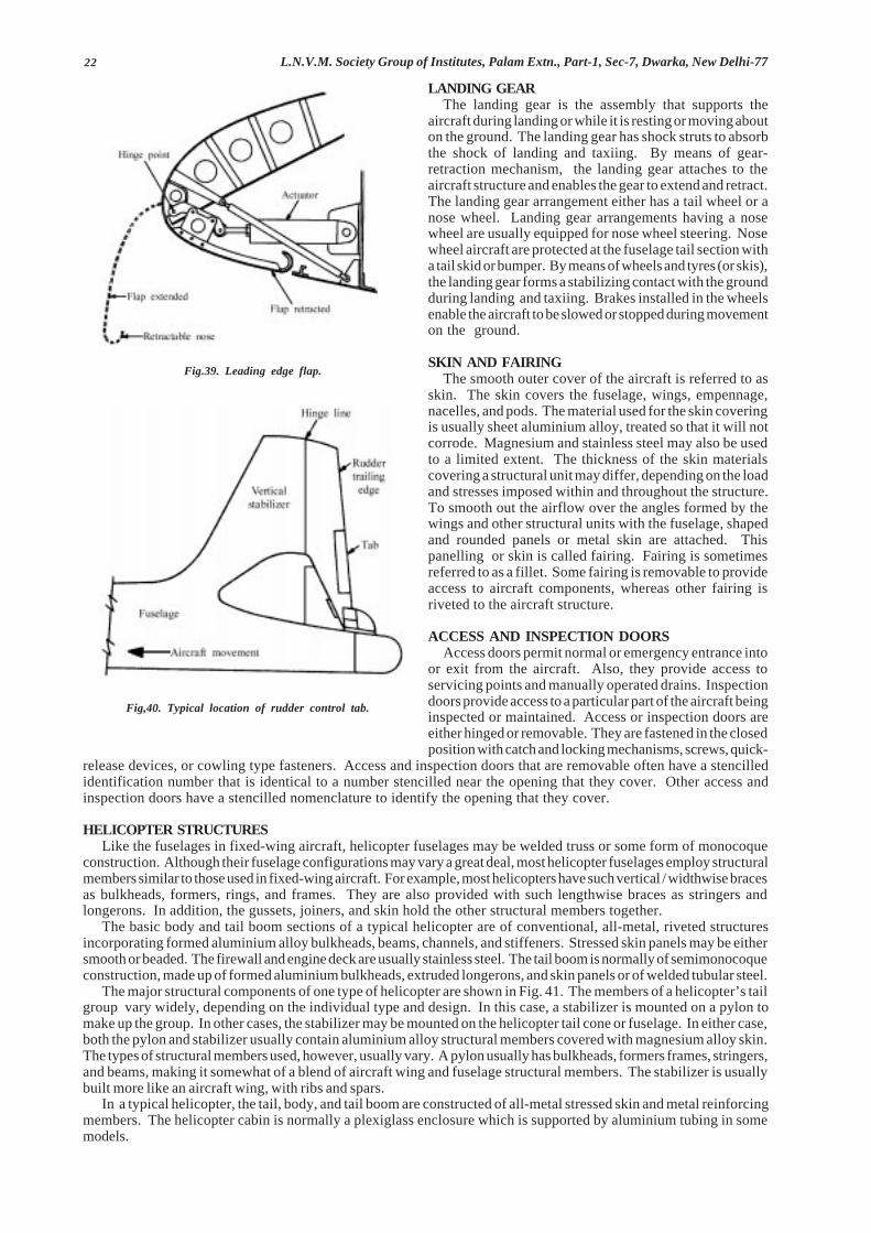
hinge line, worm-gear drives move the flaps leading edgerearward as the flaps droop. This action provides normalflap effect, and, at the same time, wing area is increasedwhen the flaps are extended.An example of a triple-slotted segmented flap used on
some large turbine aircraft is shown in Fig. 37. This typeof trailing edge flap system provides high lift for bothtakeoff and landing. Each flap consists of a fore flap, a mid-flap, and an aft-flap. The chord length of each flapexpands as the flap is extended, providing greatly increasedflap area. The resulting slots between flaps preventsseparation of the airflow over the flap area.The leading edge flap (Fig. 38) is similar in operation to
the plain flap; that is, it is hinged on the bottom side, and,when actuated, the leading edge of the wing extends in adownward direction to increase the camber of the wing.Leading edge flaps are used in conjunction with othertypes of flaps.Fig.34 shows the location of the leading edge flaps on a
large multi-engine turbine aircraft. Three Kruger-typeflaps are installed on each wing. The flaps are machinedmagnesium castings with integral ribs and stiffeners. Themagnesium casting of each flap is the principal structuralcomponent and consists of a straight section with ahollow core called the torque tube extending from thestraight section at the forward end.Each leading edge flap has three goose neck hinges
attached to fittings in the fixed wing leading edge, andhinged fairing is installed on the trailing edge of each flap.Fig.39 shows a typical leading edge flap in retractedposition, with an outline of the extended position.Speed brakes, sometimes called dive flaps or dive brakes,
serve to slow an aircraft in flight. These brakes are usedwhen descending at a steep angle or when approachingthe runway for a landing. The brake, themselves aremanufactured in many shapes, and their location dependson the design of the aircraft and the purpose of the brakes.The brake panels may be located on certain parts of the
fuselage or on the wing surfaces. Brakes on the fuselageare small panels that can be extended into the smoothairflow to create turbulence and drag. Wing-type brakesmay be multiple finger channels extending above andbelow the wing surfaces to break up smooth airflow.Usually speed brakes are controlled by electrical switchesand actuated by hydraulic pressure.Another type of air brake is a combination of spoilers and
speed brakes. A typical combination consists of spoilerflaps located in the upper wing surfaces ahead of theailerons. When the operator wishes to use both air brakesand spoilers, he can slow the flight speed and maintain lateral control as well.
Spoilers are auxiliary wing flight control surfaces, mounted on the upper surface of each wing, which operate inconjunction with the ailerons to provide lateral control.
Most spoiler systems can also be extended symmetrically to serve a secondary function as speed brakes. Othersystems are equipped with separate ground and flight spoilers. Most spoiler panels are bonded honeycomb structureswith aluminium skin. They are attached to the wing structure by machined hinge fittings which are bonded into thespoiler panel.
TabsOne of the simplest yet most important devices to aid the pilot of an aircraft is the tab attached to a control surface.
Although a tab does not take the place of a control surface, it is mounted on or attached to a movable control surfaceand causes easier movement or better balance of the control surface.
All aircraft, except a few of the very lightest types, are equipped with tabs that can be controlled from the cockpit.Tabs on some of these aircraft are usually adjustable only when the aircraft is on the ground. Fig. 40 shows the locationof a typical rudder tab.
Fig. 36.Wing flaps.
Fig. 37.Triple slotted trailing edge flap.
Fig.38. Cross section of a leading edge flap.
22 L.N.V.M. Society Group of Institutes, Palam Extn., Part-1, Sec-7, Dwarka, New Delhi-77
LANDING GEARThe landing gear is the assembly that supports the
aircraft during landing or while it is resting or moving abouton the ground. The landing gear has shock struts to absorbthe shock of landing and taxiing. By means of gear-retraction mechanism, the landing gear attaches to theaircraft structure and enables the gear to extend and retract.The landing gear arrangement either has a tail wheel or anose wheel. Landing gear arrangements having a nosewheel are usually equipped for nose wheel steering. Nosewheel aircraft are protected at the fuselage tail section witha tail skid or bumper. By means of wheels and tyres (or skis),the landing gear forms a stabilizing contact with the groundduring landing and taxiing. Brakes installed in the wheelsenable the aircraft to be slowed or stopped during movementon the ground.
SKIN AND FAIRINGThe smooth outer cover of the aircraft is referred to as
skin. The skin covers the fuselage, wings, empennage,nacelles, and pods. The material used for the skin coveringis usually sheet aluminium alloy, treated so that it will notcorrode. Magnesium and stainless steel may also be usedto a limited extent. The thickness of the skin materialscovering a structural unit may differ, depending on the loadand stresses imposed within and throughout the structure.To smooth out the airflow over the angles formed by thewings and other structural units with the fuselage, shapedand rounded panels or metal skin are attached. Thispanelling or skin is called fairing. Fairing is sometimesreferred to as a fillet. Some fairing is removable to provideaccess to aircraft components, whereas other fairing isriveted to the aircraft structure.
ACCESS AND INSPECTION DOORSAccess doors permit normal or emergency entrance into
or exit from the aircraft. Also, they provide access toservicing points and manually operated drains. Inspectiondoors provide access to a particular part of the aircraft beinginspected or maintained. Access or inspection doors areeither hinged or removable. They are fastened in the closedposition with catch and locking mechanisms, screws, quick-
release devices, or cowling type fasteners. Access and inspection doors that are removable often have a stencilledidentification number that is identical to a number stencilled near the opening that they cover. Other access andinspection doors have a stencilled nomenclature to identify the opening that they cover.
HELICOPTER STRUCTURESLike the fuselages in fixed-wing aircraft, helicopter fuselages may be welded truss or some form of monocoque
construction. Although their fuselage configurations may vary a great deal, most helicopter fuselages employ structuralmembers similar to those used in fixed-wing aircraft. For example, most helicopters have such vertical / widthwise bracesas bulkheads, formers, rings, and frames. They are also provided with such lengthwise braces as stringers andlongerons. In addition, the gussets, joiners, and skin hold the other structural members together.
The basic body and tail boom sections of a typical helicopter are of conventional, all-metal, riveted structuresincorporating formed aluminium alloy bulkheads, beams, channels, and stiffeners. Stressed skin panels may be eithersmooth or beaded. The firewall and engine deck are usually stainless steel. The tail boom is normally of semimonocoqueconstruction, made up of formed aluminium bulkheads, extruded longerons, and skin panels or of welded tubular steel.
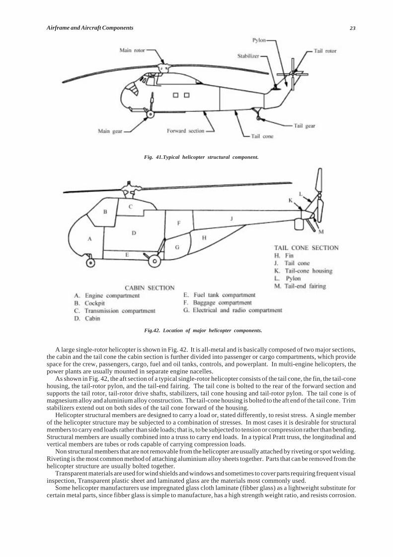
The major structural components of one type of helicopter are shown in Fig. 41. The members of a helicopter’s tailgroup vary widely, depending on the individual type and design. In this case, a stabilizer is mounted on a pylon tomake up the group. In other cases, the stabilizer may be mounted on the helicopter tail cone or fuselage. In either case,both the pylon and stabilizer usually contain aluminium alloy structural members covered with magnesium alloy skin.The types of structural members used, however, usually vary. A pylon usually has bulkheads, formers frames, stringers,and beams, making it somewhat of a blend of aircraft wing and fuselage structural members. The stabilizer is usuallybuilt more like an aircraft wing, with ribs and spars.
In a typical helicopter, the tail, body, and tail boom are constructed of all-metal stressed skin and metal reinforcingmembers. The helicopter cabin is normally a plexiglass enclosure which is supported by aluminium tubing in somemodels.
Fig.39. Leading edge flap.
Fig,40. Typical location of rudder control tab.
23Airframe and Aircraft Components
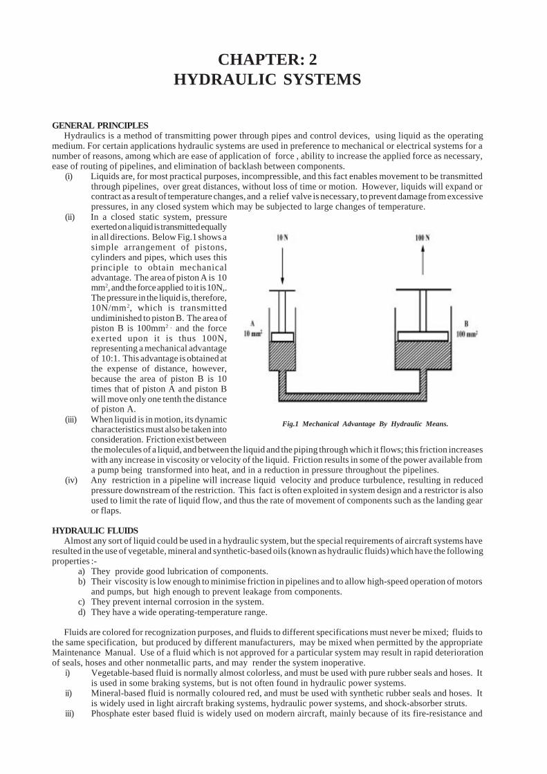
A large single-rotor helicopter is shown in Fig. 42. It is all-metal and is basically composed of two major sections,the cabin and the tail cone the cabin section is further divided into passenger or cargo compartments, which providespace for the crew, passengers, cargo, fuel and oil tanks, controls, and powerplant. In multi-engine helicopters, thepower plants are usually mounted in separate engine nacelles.
As shown in Fig. 42, the aft section of a typical single-rotor helicopter consists of the tail cone, the fin, the tail-conehousing, the tail-rotor pylon, and the tail-end fairing. The tail cone is bolted to the rear of the forward section andsupports the tail rotor, tail-rotor drive shafts, stabilizers, tail cone housing and tail-rotor pylon. The tail cone is ofmagnesium alloy and aluminium alloy construction. The tail-cone housing is bolted to the aft end of the tail cone. Trimstabilizers extend out on both sides of the tail cone forward of the housing.
Helicopter structural members are designed to carry a load or, stated differently, to resist stress. A single memberof the helicopter structure may be subjected to a combination of stresses. In most cases it is desirable for structuralmembers to carry end loads rather than side loads; that is, to be subjected to tension or compression rather than bending.Structural members are usually combined into a truss to carry end loads. In a typical Pratt truss, the longitudinal andvertical members are tubes or rods capable of carrying compression loads.
Non structural members that are not removable from the helicopter are usually attached by riveting or spot welding.Riveting is the most common method of attaching aluminium alloy sheets together. Parts that can be removed from thehelicopter structure are usually bolted together.
Transparent materials are used for wind shields and windows and sometimes to cover parts requiring frequent visualinspection, Transparent plastic sheet and laminated glass are the materials most commonly used.
Some helicopter manufacturers use impregnated glass cloth laminate (fibber glass) as a lightweight substitute forcertain metal parts, since fibber glass is simple to manufacture, has a high strength weight ratio, and resists corrosion.
� � �
Fig. 41.Typical helicopter structural component.
Fig.42. Location of major helicopter components.
24 L.N.V.M. Society Group of Institutes, Palam Extn., Part-1, Sec-7, Dwarka, New Delhi-77
CHAPTER: 2HYDRAULIC SYSTEMS
GENERAL PRINCIPLESHydraulics is a method of transmitting power through pipes and control devices, using liquid as the operating
medium. For certain applications hydraulic systems are used in preference to mechanical or electrical systems for anumber of reasons, among which are ease of application of force , ability to increase the applied force as necessary,ease of routing of pipelines, and elimination of backlash between components.
(i) Liquids are, for most practical purposes, incompressible, and this fact enables movement to be transmittedthrough pipelines, over great distances, without loss of time or motion. However, liquids will expand orcontract as a result of temperature changes, and a relief valve is necessary, to prevent damage from excessivepressures, in any closed system which may be subjected to large changes of temperature.
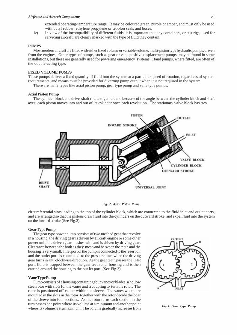
(ii) In a closed static system, pressureexerted on a liquid is transmitted equallyin all directions. Below Fig.1 shows asimple arrangement of pistons,cylinders and pipes, which uses thisprinciple to obtain mechanicaladvantage. The area of piston A is 10mm2, and the force applied to it is 10N,.The pressure in the liquid is, therefore,10N/mm2, which is transmittedundiminished to piston B. The area ofpiston B is 100mm2 , and the forceexerted upon it is thus 100N,representing a mechanical advantageof 10:1. This advantage is obtained atthe expense of distance, however,because the area of piston B is 10times that of piston A and piston Bwill move only one tenth the distanceof piston A.
(iii) When liquid is in motion, its dynamiccharacteristics must also be taken intoconsideration. Friction exist betweenthe molecules of a liquid, and between the liquid and the piping through which it flows; this friction increaseswith any increase in viscosity or velocity of the liquid. Friction results in some of the power available froma pump being transformed into heat, and in a reduction in pressure throughout the pipelines.
(iv) Any restriction in a pipeline will increase liquid velocity and produce turbulence, resulting in reducedpressure downstream of the restriction. This fact is often exploited in system design and a restrictor is alsoused to limit the rate of liquid flow, and thus the rate of movement of components such as the landing gearor flaps.
HYDRAULIC FLUIDSAlmost any sort of liquid could be used in a hydraulic system, but the special requirements of aircraft systems have
resulted in the use of vegetable, mineral and synthetic-based oils (known as hydraulic fluids) which have the followingproperties :-
a) They provide good lubrication of components.b) Their viscosity is low enough to minimise friction in pipelines and to allow high-speed operation of motors
and pumps, but high enough to prevent leakage from components.c) They prevent internal corrosion in the system.d) They have a wide operating-temperature range.
Fluids are colored for recognization purposes, and fluids to different specifications must never be mixed; fluids tothe same specification, but produced by different manufacturers, may be mixed when permitted by the appropriateMaintenance Manual. Use of a fluid which is not approved for a particular system may result in rapid deteriorationof seals, hoses and other nonmetallic parts, and may render the system inoperative.
i) Vegetable-based fluid is normally almost colorless, and must be used with pure rubber seals and hoses. Itis used in some braking systems, but is not often found in hydraulic power systems.
ii) Mineral-based fluid is normally coloured red, and must be used with synthetic rubber seals and hoses. Itis widely used in light aircraft braking systems, hydraulic power systems, and shock-absorber struts.
iii) Phosphate ester based fluid is widely used on modern aircraft, mainly because of its fire-resistance and
Fig.1 Mechanical Advantage By Hydraulic Means.
25Airframe and Aircraft Components
extended operating-temperature range. It may be coloured green, purple or amber, and must only be usedwith butyl rubber, ethylene propylene or tebblon seals and hoses.
iv) In view of the incompatibility of different fluids, it is important that any containers, or test rigs, used forservicing aircraft, are clearly marked with the type of fluid they contain.
PUMPSMost modern aircraft are fitted with either fixed volume or variable volume, multi-piston type hydraulic pumps, driven
from the engines. Other types of pumps, such as gear or vane positive displacement pumps, may be found in someinstallations, but these are generally used for powering emergency systems. Hand pumps, where fitted, are often ofthe double-acting type.
FIXED VOLUME PUMPSThese pumps deliver a fixed quantity of fluid into the system at a particular speed of rotation, regardless of systemrequirements, and means must be provided for diverting pump output when it is not required in the system.
There are many types like axial piston pump, gear type pump and vane type pumps.
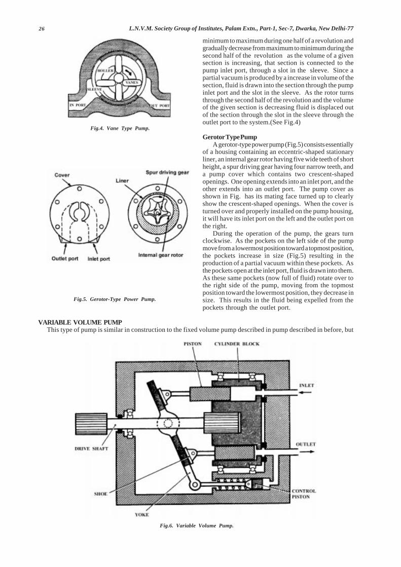
Axial Piston PumpThe cylinder block and drive shaft rotate together, and because of the angle between the cylinder block and shaft
axes, each piston moves into and out of its cylinder once each revolution. The stationary valve block has two
Fig. 2. Axial Piston Pump.
circumferential slots leading to the top of the cylinder block, which are connected to the fluid inlet and outlet ports,and are arranged so that the pistons draw fluid into the cylinders on the outward stroke, and expel fluid into the systemon the inward stroke.(See Fig.2)
Gear Type PumpThe gear type power pump consists of two meshed gear that revolve
in a housing, the driving gear is driven by aircraft engine or some otherpower unit, the driven gear meshes with and is driven by driving gear.Clearance between the both as they mesh and between the teeth and thehousing is very small. Inlet port of the pump is connected to the reservoirand the outlet port is connected to the pressure line, when the drivinggear turns in anti clockwise direction. As the gear teeth passes the inletport, fluid is trapped between the gear teeth and housing and is thencarried around the housing to the out let port. (See Fig.3)
Vane Type PumpPump consists of a housing containing four vanes or blades, a hollow
steel rotor with slots for the vanes and a coupling to turn the rotor. Therotor is positioned off center within the sleeve. The vanes which aremounted in the slots in the rotor, together with the rotor decide the boarof the sleeve into four sections. As the rotor turns each section in theturn passes one point where its volume at a minimum and another pointwhere its volume is at a maximum. The volume gradually increases from
Fig.3. Gear Type Pump.
26 L.N.V.M. Society Group of Institutes, Palam Extn., Part-1, Sec-7, Dwarka, New Delhi-77
minimum to maximum during one half of a revolution andgradually decrease from maximum to minimum during thesecond half of the revolution as the volume of a givensection is increasing, that section is connected to thepump inlet port, through a slot in the sleeve. Since apartial vacuum is produced by a increase in volume of thesection, fluid is drawn into the section through the pumpinlet port and the slot in the sleeve. As the rotor turnsthrough the second half of the revolution and the volumeof the given section is decreasing fluid is displaced outof the section through the slot in the sleeve through theoutlet port to the system.(See Fig.4)
Gerotor Type PumpA gerotor-type power pump (Fig.5) consists essentially
of a housing containing an eccentric-shaped stationaryliner, an internal gear rotor having five wide teeth of shortheight, a spur driving gear having four narrow teeth, anda pump cover which contains two crescent-shapedopenings. One opening extends into an inlet port, and theother extends into an outlet port. The pump cover asshown in Fig. has its mating face turned up to clearlyshow the crescent-shaped openings. When the cover isturned over and properly installed on the pump housing,it will have its inlet port on the left and the outlet port onthe right.
During the operation of the pump, the gears turnclockwise. As the pockets on the left side of the pumpmove from a lowermost position toward a topmost position,the pockets increase in size (Fig.5) resulting in theproduction of a partial vacuum within these pockets. Asthe pockets open at the inlet port, fluid is drawn into them.As these same pockets (now full of fluid) rotate over tothe right side of the pump, moving from the topmostposition toward the lowermost position, they decrease insize. This results in the fluid being expelled from thepockets through the outlet port.
VARIABLE VOLUME PUMPThis type of pump is similar in construction to the fixed volume pump described in pump described in before, but
Fig.4. Vane Type Pump.
Fig.6. Variable Volume Pump.
Fig.5. Gerotor-Type Power Pump.
27Airframe and Aircraft Components
the cylinder block and drive shaft are co-axial. The pistons are attached to shoes which rotate against a stationaryyoke, and the angle between the yoke and cylinder block is varied to increase or decrease pump stroke to suit systemrequirements. Fig. 6 shows the operation of the pump. When pressure in the system is low, as would be the case followingselection of a service, spring pressure on the control piston turns the yoke to its maximum angle, and the pistons areat full stroke, delivering maximum output to the system. When the actuator has completed its stroke, pressure buildsup until the control piston moves the yoke to the minimum stroke position; in this position a small flow through thepump is maintained, to lubricate the working parts, overcome internal leakage and dissipate heat. On some pumps asolenoid-operated depressurizing valve is used to block delivery to the system, and to off-load the pump.
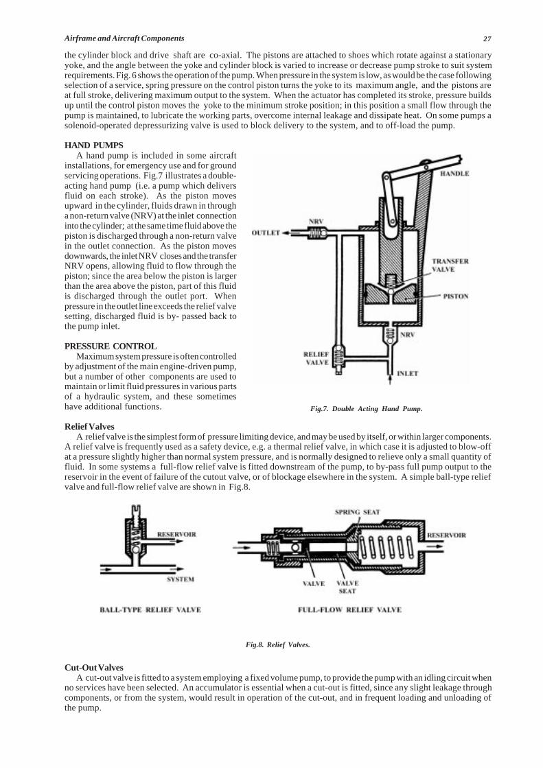
HAND PUMPSA hand pump is included in some aircraft
installations, for emergency use and for groundservicing operations. Fig.7 illustrates a double-acting hand pump (i.e. a pump which deliversfluid on each stroke). As the piston movesupward in the cylinder, fluids drawn in througha non-return valve (NRV) at the inlet connectioninto the cylinder; at the same time fluid above thepiston is discharged through a non-return valvein the outlet connection. As the piston movesdownwards, the inlet NRV closes and the transferNRV opens, allowing fluid to flow through thepiston; since the area below the piston is largerthan the area above the piston, part of this fluidis discharged through the outlet port. Whenpressure in the outlet line exceeds the relief valvesetting, discharged fluid is by- passed back tothe pump inlet.
PRESSURE CONTROLMaximum system pressure is often controlled
by adjustment of the main engine-driven pump,but a number of other components are used tomaintain or limit fluid pressures in various partsof a hydraulic system, and these sometimeshave additional functions.
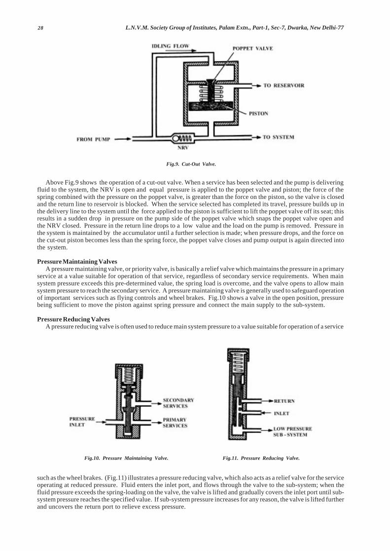
Relief ValvesA relief valve is the simplest form of pressure limiting device, and may be used by itself, or within larger components.
A relief valve is frequently used as a safety device, e.g. a thermal relief valve, in which case it is adjusted to blow-offat a pressure slightly higher than normal system pressure, and is normally designed to relieve only a small quantity offluid. In some systems a full-flow relief valve is fitted downstream of the pump, to by-pass full pump output to thereservoir in the event of failure of the cutout valve, or of blockage elsewhere in the system. A simple ball-type reliefvalve and full-flow relief valve are shown in Fig.8.
Cut-Out ValvesA cut-out valve is fitted to a system employing a fixed volume pump, to provide the pump with an idling circuit when
no services have been selected. An accumulator is essential when a cut-out is fitted, since any slight leakage throughcomponents, or from the system, would result in operation of the cut-out, and in frequent loading and unloading ofthe pump.
Fig.7. Double Acting Hand Pump.
Fig.8. Relief Valves.
28 L.N.V.M. Society Group of Institutes, Palam Extn., Part-1, Sec-7, Dwarka, New Delhi-77
Above Fig.9 shows the operation of a cut-out valve. When a service has been selected and the pump is deliveringfluid to the system, the NRV is open and equal pressure is applied to the poppet valve and piston; the force of thespring combined with the pressure on the poppet valve, is greater than the force on the piston, so the valve is closedand the return line to reservoir is blocked. When the service selected has completed its travel, pressure builds up inthe delivery line to the system until the force applied to the piston is sufficient to lift the poppet valve off its seat; thisresults in a sudden drop in pressure on the pump side of the poppet valve which snaps the poppet valve open andthe NRV closed. Pressure in the return line drops to a low value and the load on the pump is removed. Pressure inthe system is maintained by the accumulator until a further selection is made; when pressure drops, and the force onthe cut-out piston becomes less than the spring force, the poppet valve closes and pump output is again directed intothe system.
Pressure Maintaining ValvesA pressure maintaining valve, or priority valve, is basically a relief valve which maintains the pressure in a primary
service at a value suitable for operation of that service, regardless of secondary service requirements. When mainsystem pressure exceeds this pre-determined value, the spring load is overcome, and the valve opens to allow mainsystem pressure to reach the secondary service. A pressure maintaining valve is generally used to safeguard operationof important services such as flying controls and wheel brakes. Fig.10 shows a valve in the open position, pressurebeing sufficient to move the piston against spring pressure and connect the main supply to the sub-system.
Pressure Reducing ValvesA pressure reducing valve is often used to reduce main system pressure to a value suitable for operation of a service
such as the wheel brakes. (Fig.11) illustrates a pressure reducing valve, which also acts as a relief valve for the serviceoperating at reduced pressure. Fluid enters the inlet port, and flows through the valve to the sub-system; when thefluid pressure exceeds the spring-loading on the valve, the valve is lifted and gradually covers the inlet port until sub-system pressure reaches the specified value. If sub-system pressure increases for any reason, the valve is lifted furtherand uncovers the return port to relieve excess pressure.
Fig.10. Pressure Maintaining Valve. Fig.11. Pressure Reducing Valve.
Fig.9. Cut-Out Valve.
29Airframe and Aircraft Components
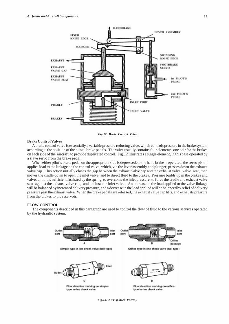
Brake Control ValvesA brake control valve is essentially a variable pressure reducing valve, which controls pressure in the brake system
according to the position of the pilots’ brake pedals. The valve usually contains four elements, one pair for the brakeson each side of the aircraft, to provide duplicated control. Fig.12 illustrates a single element, in this case operated bya slave servo from the brake pedal.
When either pilot’s brake pedal on the appropriate side is depressed, or the hand brake is operated, the servo pistonapplies load to the linkage on the control valve, which, via the lever assembly and plunger, presses down the exhaustvalve cap. This action initially closes the gap between the exhaust valve cap and the exhaust valve, valve seat, thenmoves the cradle down to open the inlet valve, and to direct fluid to the brakes. Pressure builds up in the brakes andvalve, until it is sufficient, assisted by the spring, to overcome the inlet pressure, to force the cradle and exhaust valveseat against the exhaust valve cap, and to close the inlet valve. An increase in the load applied to the valve linkagewill be balanced by increased delivery pressure, and a decrease in the load applied will be balanced by relief of deliverypressure past the exhaust valve. When the brake pedals are released, the exhaust valve cap lifts, and exhausts pressurefrom the brakes to the reservoir.
FLOW CONTROLThe components described in this paragraph are used to control the flow of fluid to the various services operated
by the hydraulic system.
Fig.12. Brake Control Valve.
Fig.13. NRV (Check Valves).
30 L.N.V.M. Society Group of Institutes, Palam Extn., Part-1, Sec-7, Dwarka, New Delhi-77
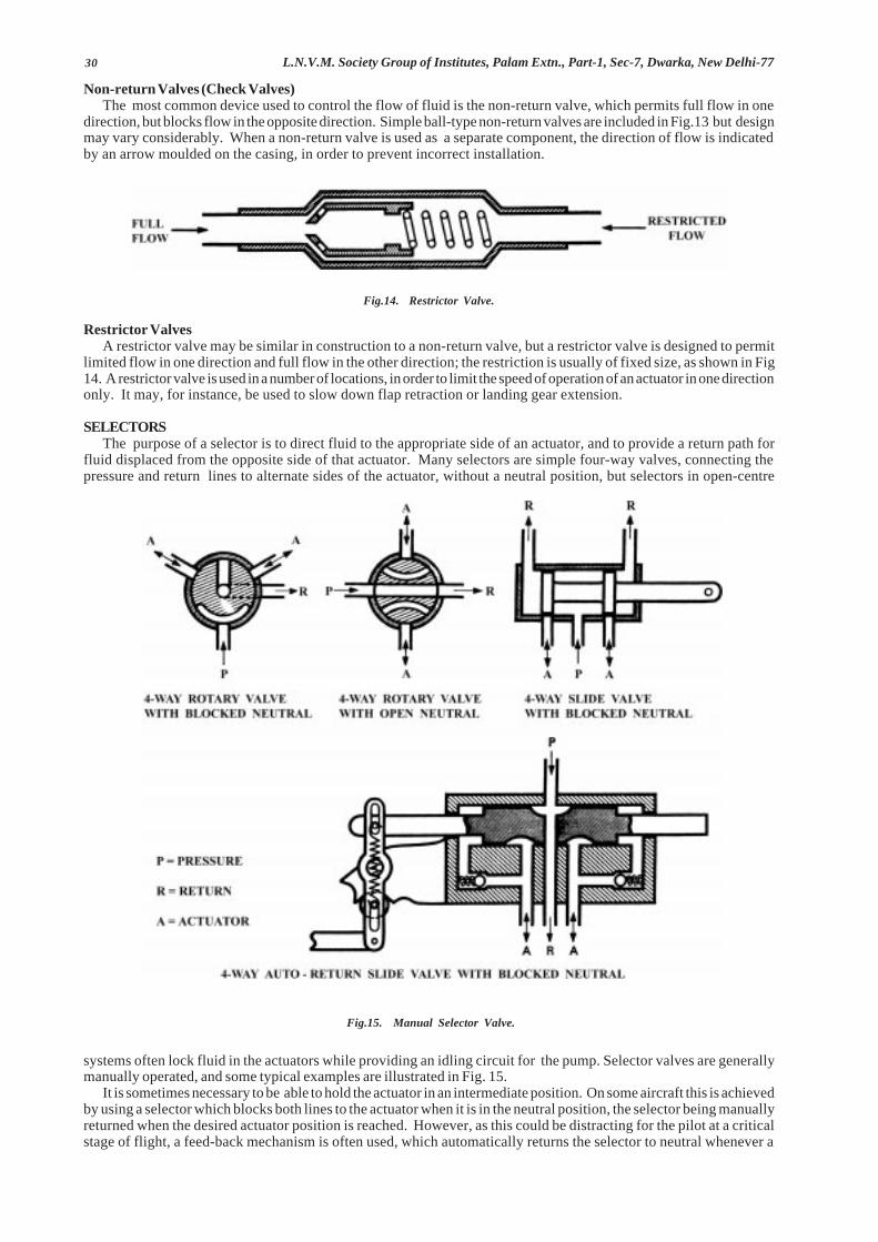
Non-return Valves (Check Valves)The most common device used to control the flow of fluid is the non-return valve, which permits full flow in one
direction, but blocks flow in the opposite direction. Simple ball-type non-return valves are included in Fig.13 but designmay vary considerably. When a non-return valve is used as a separate component, the direction of flow is indicatedby an arrow moulded on the casing, in order to prevent incorrect installation.
Fig.14. Restrictor Valve.
Restrictor ValvesA restrictor valve may be similar in construction to a non-return valve, but a restrictor valve is designed to permit
limited flow in one direction and full flow in the other direction; the restriction is usually of fixed size, as shown in Fig14. A restrictor valve is used in a number of locations, in order to limit the speed of operation of an actuator in one directiononly. It may, for instance, be used to slow down flap retraction or landing gear extension.
SELECTORSThe purpose of a selector is to direct fluid to the appropriate side of an actuator, and to provide a return path for
fluid displaced from the opposite side of that actuator. Many selectors are simple four-way valves, connecting thepressure and return lines to alternate sides of the actuator, without a neutral position, but selectors in open-centre
systems often lock fluid in the actuators while providing an idling circuit for the pump. Selector valves are generallymanually operated, and some typical examples are illustrated in Fig. 15.
It is sometimes necessary to be able to hold the actuator in an intermediate position. On some aircraft this is achievedby using a selector which blocks both lines to the actuator when it is in the neutral position, the selector being manuallyreturned when the desired actuator position is reached. However, as this could be distracting for the pilot at a criticalstage of flight, a feed-back mechanism is often used, which automatically returns the selector to neutral whenever a
Fig.15. Manual Selector Valve.
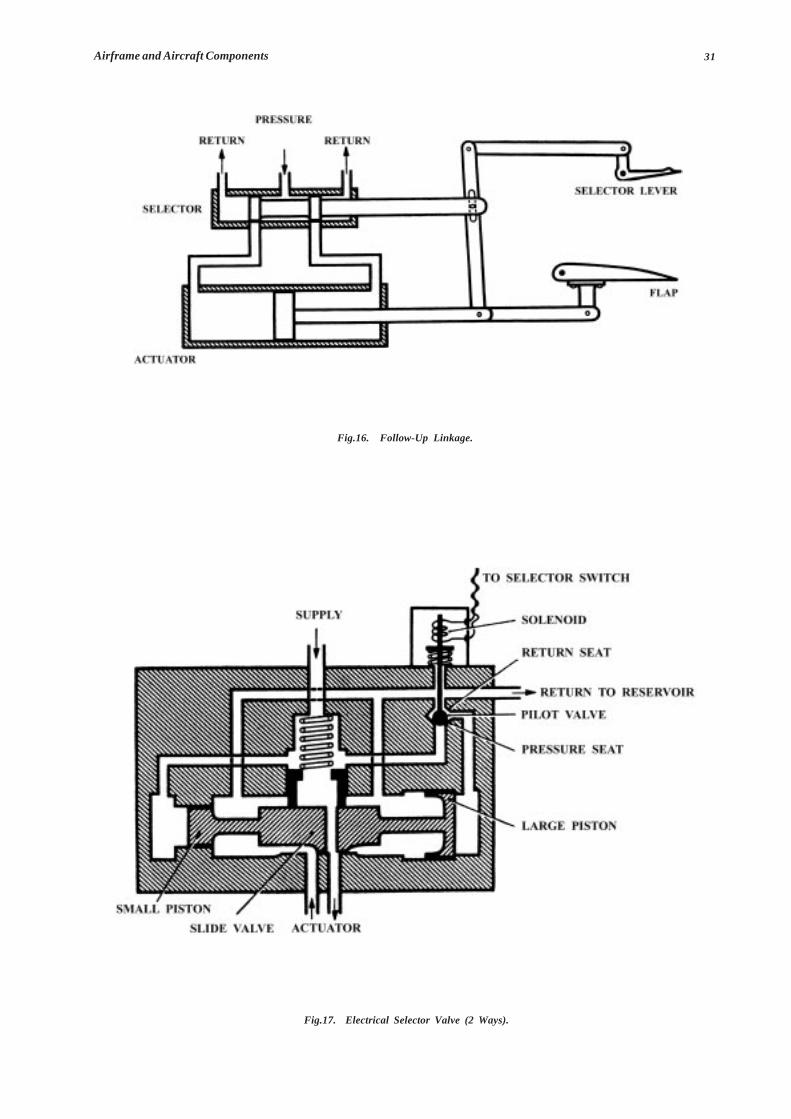
31Airframe and Aircraft Components
Fig.16. Follow-Up Linkage.
Fig.17. Electrical Selector Valve (2 Ways).
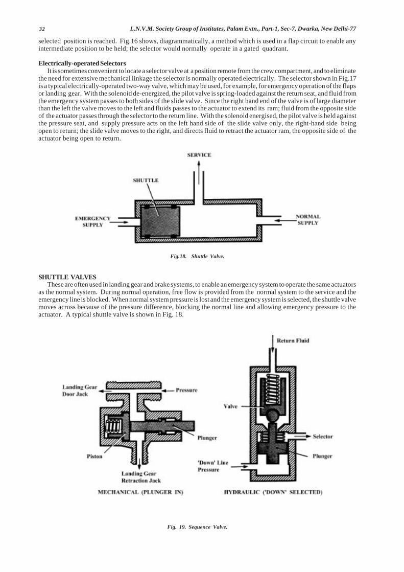
32 L.N.V.M. Society Group of Institutes, Palam Extn., Part-1, Sec-7, Dwarka, New Delhi-77
selected position is reached. Fig.16 shows, diagrammatically, a method which is used in a flap circuit to enable anyintermediate position to be held; the selector would normally operate in a gated quadrant.
Electrically-operated SelectorsIt is sometimes convenient to locate a selector valve at a position remote from the crew compartment, and to eliminate
the need for extensive mechanical linkage the selector is normally operated electrically. The selector shown in Fig.17is a typical electrically-operated two-way valve, which may be used, for example, for emergency operation of the flapsor landing gear. With the solenoid de-energized, the pilot valve is spring-loaded against the return seat, and fluid fromthe emergency system passes to both sides of the slide valve. Since the right hand end of the valve is of large diameterthan the left the valve moves to the left and fluids passes to the actuator to extend its ram; fluid from the opposite sideof the actuator passes through the selector to the return line. With the solenoid energised, the pilot valve is held againstthe pressure seat, and supply pressure acts on the left hand side of the slide valve only, the right-hand side beingopen to return; the slide valve moves to the right, and directs fluid to retract the actuator ram, the opposite side of theactuator being open to return.
Fig.18. Shuttle Valve.
SHUTTLE VALVESThese are often used in landing gear and brake systems, to enable an emergency system to operate the same actuators
as the normal system. During normal operation, free flow is provided from the normal system to the service and theemergency line is blocked. When normal system pressure is lost and the emergency system is selected, the shuttle valvemoves across because of the pressure difference, blocking the normal line and allowing emergency pressure to theactuator. A typical shuttle valve is shown in Fig. 18.
Fig. 19. Sequence Valve.
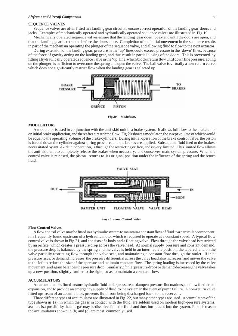
33Airframe and Aircraft Components
SEQUENCE VALVESSequence valves are often fitted in a landing gear circuit to ensure correct operation of the landing gear doors and
jacks. Examples of mechanically operated and hydraulically operated sequence valves are illustrated in Fig.19.Mechanically operated sequence valves ensure that the landing gear does not extend until the doors are open, and
that the landing gear is retracted before the doors close. Completion of the initial movement in the sequence resultsin part of the mechanism operating the plunger of the sequence valve, and allowing fluid to flow to the next actuator.
During extension of the landing gear, pressure in the ‘up’ lines could exceed pressure in the ‘down’ lines, becauseof the force of gravity acting on the landing gear, and thus result in partial closing of the doors. This is prevented byfitting a hydraulically operated sequence valve in the ‘up’ line, which blocks return flow until down line pressure, actingon the plunger, is sufficient to overcome the spring and open the valve. The ball valve is virtually a non-return valve,which does not significantly restrict flow when the landing gear is selected up.
Fig.20. Modulator.
MODULATORSA modulator is used in conjunction with the anti-skid unit in a brake system. It allows full flow to the brake units
on initial brake application, and thereafter a restricted flow. Fig.20 shows a modulator, the swept volume of which wouldbe equal to the operating volume of the brake cylinders. During initial operation of the brake control valve, the pistonis forced down the cylinder against spring pressure, and the brakes are applied. Subsequent fluid feed to the brakes,necessitated by anti-skid unit operation, is through the restricting orifice, and is very limited. This limited flow allowsthe anti-skid unit to completely release the brakes when necessary, and conserves main system pressure. When thecontrol valve is released, the piston returns to its original position under the influence of the spring and the returnfluid.
Fig.21. Flow Control Valve.
Flow Control ValvesA flow control valve may be fitted in a hydraulic system to maintain a constant flow of fluid to a particular component;
it is frequently found upstream of a hydraulic motor which is required to operate at a constant speed. A typical flowcontrol valve is shown in Fig.21, and consists of a body and a floating valve. Flow through the valve head is restrictedby an orifice, which creates a pressure drop across the valve head. At normal supply pressure and constant demand,the pressure drop is balanced by the spring and the valve is held in an intermediate position, the tapered land on thevalve partially restricting flow through the valve seat, and maintaining a constant flow through the outlet. If inletpressure rises, or demand increases, the pressure differential across the valve head also increases, and moves the valveto the left to reduce the size of the aperture and maintain constant flow. The spring loading is increased by the valvemovement, and again balances the pressure drop. Similarly, if inlet pressure drops or demand decreases, the valve takesup a new position, slightly further to the right, so as to maintain a constant flow.
ACCUMULATORSAn accumulator is fitted to store hydraulic fluid under pressure, to dampen pressure fluctuations, to allow for thermal
expansion, and to provide an emergency supply of fluid to the system in the event of pump failure. A non-return valvefitted upstream of an accumulator, prevents fluid from being discharged back to the reservoir.
Three different types of accumulator are illustrated in Fig. 22, but many other types are used. Accumulators of thetype shown in (a), in which the gas is in contact with the fluid, are seldom used on modern high-pressure systems,as there is a possibility that the gas may be dissolved into the fluid, and thus introduced into the system. For this reasonthe accumulators shown in (b) and (c) are most commonly used.
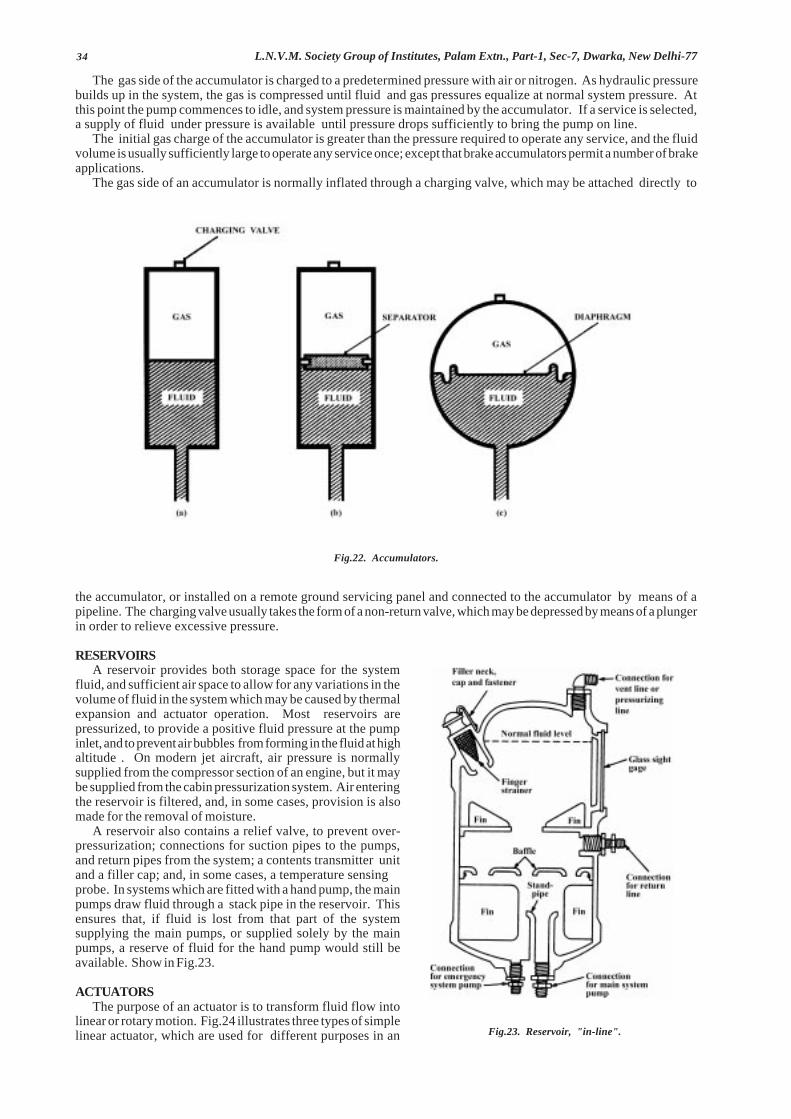
34 L.N.V.M. Society Group of Institutes, Palam Extn., Part-1, Sec-7, Dwarka, New Delhi-77
The gas side of the accumulator is charged to a predetermined pressure with air or nitrogen. As hydraulic pressurebuilds up in the system, the gas is compressed until fluid and gas pressures equalize at normal system pressure. Atthis point the pump commences to idle, and system pressure is maintained by the accumulator. If a service is selected,a supply of fluid under pressure is available until pressure drops sufficiently to bring the pump on line.
The initial gas charge of the accumulator is greater than the pressure required to operate any service, and the fluidvolume is usually sufficiently large to operate any service once; except that brake accumulators permit a number of brakeapplications.
The gas side of an accumulator is normally inflated through a charging valve, which may be attached directly to
Fig.22. Accumulators.
the accumulator, or installed on a remote ground servicing panel and connected to the accumulator by means of apipeline. The charging valve usually takes the form of a non-return valve, which may be depressed by means of a plungerin order to relieve excessive pressure.
RESERVOIRSA reservoir provides both storage space for the system
fluid, and sufficient air space to allow for any variations in thevolume of fluid in the system which may be caused by thermalexpansion and actuator operation. Most reservoirs arepressurized, to provide a positive fluid pressure at the pumpinlet, and to prevent air bubbles from forming in the fluid at highaltitude . On modern jet aircraft, air pressure is normallysupplied from the compressor section of an engine, but it maybe supplied from the cabin pressurization system. Air enteringthe reservoir is filtered, and, in some cases, provision is alsomade for the removal of moisture.
A reservoir also contains a relief valve, to prevent over-pressurization; connections for suction pipes to the pumps,and return pipes from the system; a contents transmitter unitand a filler cap; and, in some cases, a temperature sensingprobe. In systems which are fitted with a hand pump, the mainpumps draw fluid through a stack pipe in the reservoir. Thisensures that, if fluid is lost from that part of the systemsupplying the main pumps, or supplied solely by the mainpumps, a reserve of fluid for the hand pump would still beavailable. Show in Fig.23.
ACTUATORSThe purpose of an actuator is to transform fluid flow into
linear or rotary motion. Fig.24 illustrates three types of simplelinear actuator, which are used for different purposes in an Fig.23. Reservoir, "in-line".
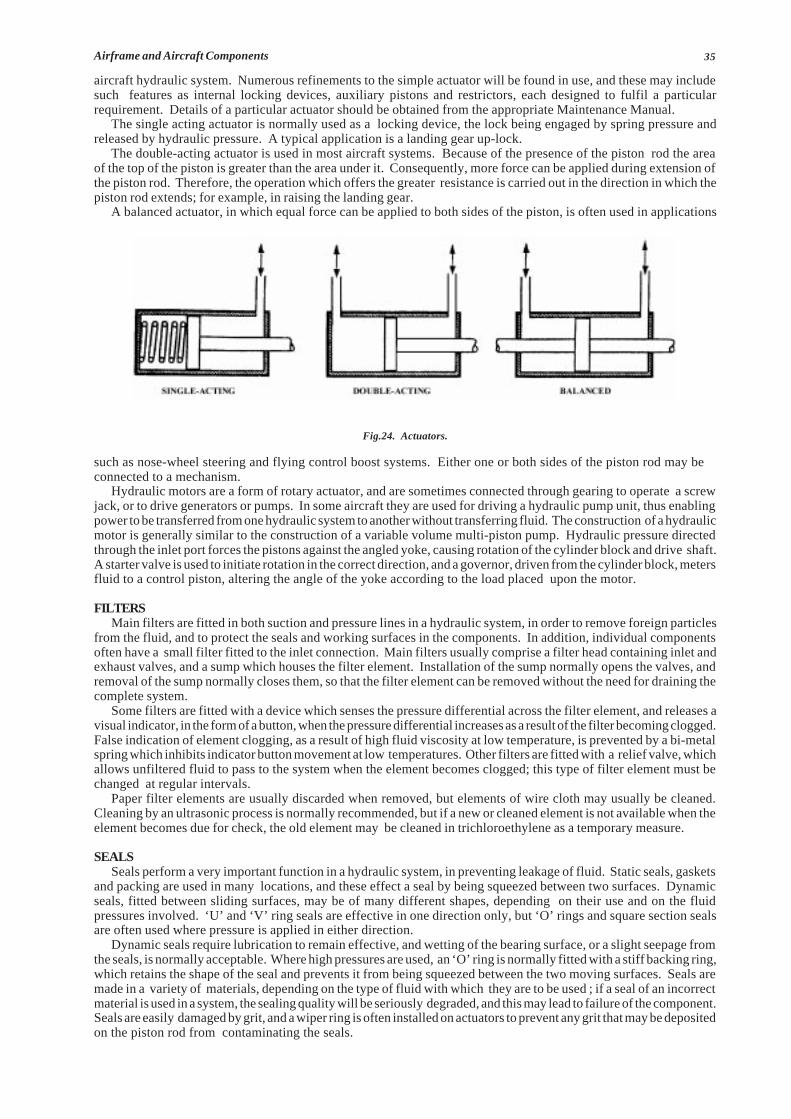
35Airframe and Aircraft Components
aircraft hydraulic system. Numerous refinements to the simple actuator will be found in use, and these may includesuch features as internal locking devices, auxiliary pistons and restrictors, each designed to fulfil a particularrequirement. Details of a particular actuator should be obtained from the appropriate Maintenance Manual.
The single acting actuator is normally used as a locking device, the lock being engaged by spring pressure andreleased by hydraulic pressure. A typical application is a landing gear up-lock.
The double-acting actuator is used in most aircraft systems. Because of the presence of the piston rod the areaof the top of the piston is greater than the area under it. Consequently, more force can be applied during extension ofthe piston rod. Therefore, the operation which offers the greater resistance is carried out in the direction in which thepiston rod extends; for example, in raising the landing gear.
A balanced actuator, in which equal force can be applied to both sides of the piston, is often used in applications
Fig.24. Actuators.
such as nose-wheel steering and flying control boost systems. Either one or both sides of the piston rod may beconnected to a mechanism.
Hydraulic motors are a form of rotary actuator, and are sometimes connected through gearing to operate a screwjack, or to drive generators or pumps. In some aircraft they are used for driving a hydraulic pump unit, thus enablingpower to be transferred from one hydraulic system to another without transferring fluid. The construction of a hydraulicmotor is generally similar to the construction of a variable volume multi-piston pump. Hydraulic pressure directedthrough the inlet port forces the pistons against the angled yoke, causing rotation of the cylinder block and drive shaft.A starter valve is used to initiate rotation in the correct direction, and a governor, driven from the cylinder block, metersfluid to a control piston, altering the angle of the yoke according to the load placed upon the motor.
FILTERSMain filters are fitted in both suction and pressure lines in a hydraulic system, in order to remove foreign particles
from the fluid, and to protect the seals and working surfaces in the components. In addition, individual componentsoften have a small filter fitted to the inlet connection. Main filters usually comprise a filter head containing inlet andexhaust valves, and a sump which houses the filter element. Installation of the sump normally opens the valves, andremoval of the sump normally closes them, so that the filter element can be removed without the need for draining thecomplete system.
Some filters are fitted with a device which senses the pressure differential across the filter element, and releases avisual indicator, in the form of a button, when the pressure differential increases as a result of the filter becoming clogged.False indication of element clogging, as a result of high fluid viscosity at low temperature, is prevented by a bi-metalspring which inhibits indicator button movement at low temperatures. Other filters are fitted with a relief valve, whichallows unfiltered fluid to pass to the system when the element becomes clogged; this type of filter element must bechanged at regular intervals.
Paper filter elements are usually discarded when removed, but elements of wire cloth may usually be cleaned.Cleaning by an ultrasonic process is normally recommended, but if a new or cleaned element is not available when theelement becomes due for check, the old element may be cleaned in trichloroethylene as a temporary measure.
SEALSSeals perform a very important function in a hydraulic system, in preventing leakage of fluid. Static seals, gaskets
and packing are used in many locations, and these effect a seal by being squeezed between two surfaces. Dynamicseals, fitted between sliding surfaces, may be of many different shapes, depending on their use and on the fluidpressures involved. ‘U’ and ‘V’ ring seals are effective in one direction only, but ‘O’ rings and square section sealsare often used where pressure is applied in either direction.
Dynamic seals require lubrication to remain effective, and wetting of the bearing surface, or a slight seepage fromthe seals, is normally acceptable. Where high pressures are used, an ‘O’ ring is normally fitted with a stiff backing ring,which retains the shape of the seal and prevents it from being squeezed between the two moving surfaces. Seals aremade in a variety of materials, depending on the type of fluid with which they are to be used ; if a seal of an incorrectmaterial is used in a system, the sealing quality will be seriously degraded, and this may lead to failure of the component.Seals are easily damaged by grit, and a wiper ring is often installed on actuators to prevent any grit that may be depositedon the piston rod from contaminating the seals.
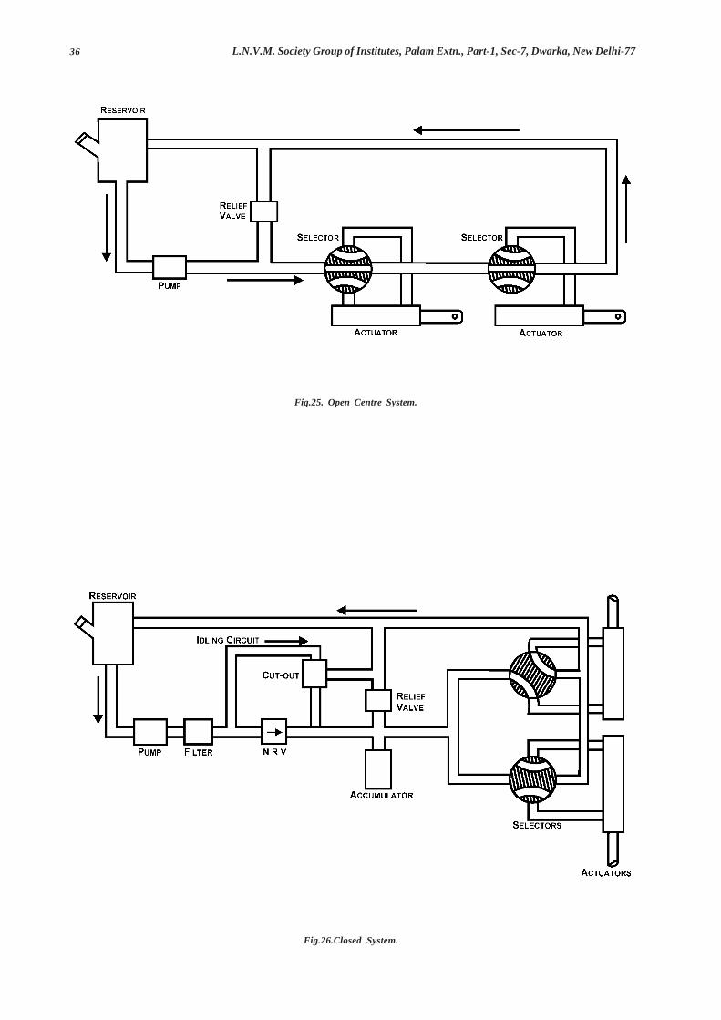
36 L.N.V.M. Society Group of Institutes, Palam Extn., Part-1, Sec-7, Dwarka, New Delhi-77
Fig.25. Open Centre System.
Fig.26.Closed System.
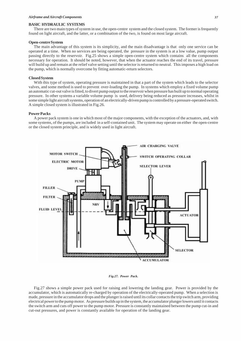
37Airframe and Aircraft Components
BASIC HYDRAULIC SYSTEMSThere are two main types of system in use, the open-centre system and the closed system. The former is frequently
found on light aircraft, and the latter, or a combination of the two, is found on most large aircraft.
Open-centre SystemThe main advantage of this system is its simplicity, and the main disadvantage is that only one service can be
operated at a time. When no services are being operated, the pressure in the system is at a low value, pump outputpassing directly to the reservoir. Fig.25 shows a simple open-centre system which contains all the componentsnecessary for operation. It should be noted, however, that when the actuator reaches the end of its travel, pressurewill build up and remain at the relief valve setting until the selector is returned to neutral. This imposes a high load onthe pump, which is normally overcome by fitting automatic-return selectors.
Closed SystemWith this type of system, operating pressure is maintained in that a part of the system which leads to the selector
valves, and some method is used to prevent over-loading the pump. In systems which employ a fixed volume pumpan automatic cut-out valve is fitted, to divert pump output to the reservoir when pressure has built up to normal operatingpressure. In other systems a variable volume pump is used, delivery being reduced as pressure increases, whilst insome simple light aircraft systems, operation of an electrically-driven pump is controlled by a pressure-operated switch.A simple closed system is illustrated in Fig.26.
Power PacksA power pack system is one in which most of the major components, with the exception of the actuators, and, with
some systems, of the pumps, are included in a self-contained unit. The system may operate on either the open-centreor the closed system principle, and is widely used in light aircraft.
Fig.27. Power Pack.
Fig.27 shows a simple power pack used for raising and lowering the landing gear. Power is provided by theaccumulator, which is automatically re-charged by operation of the electrically-operated pump. When a selection ismade, pressure in the accumulator drops and the plunger is raised until its collar contacts the trip switch arm, providingelectrical power to the pump motor. As pressure builds up in the system, the accumulator plunger lowers until it contactsthe switch arm and cuts off power to the pump motor. Pressure is constantly maintained between the pump cut-in andcut-out pressures, and power is constantly available for operation of the landing gear.
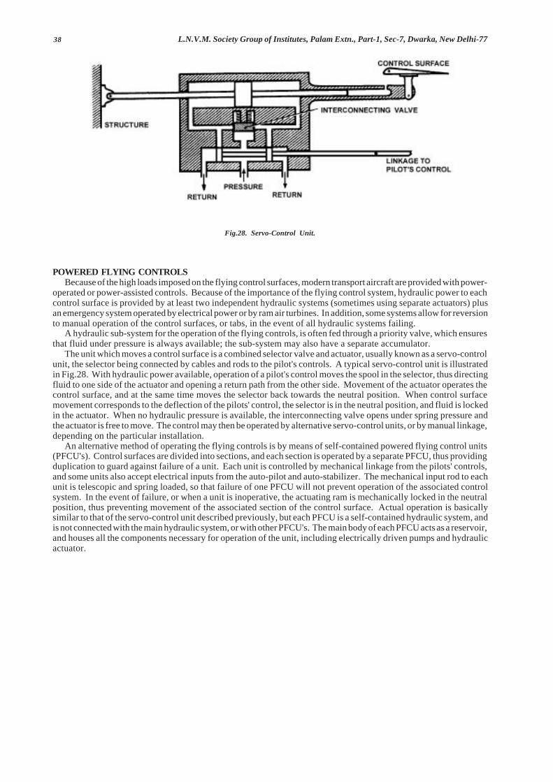
38 L.N.V.M. Society Group of Institutes, Palam Extn., Part-1, Sec-7, Dwarka, New Delhi-77
POWERED FLYING CONTROLSBecause of the high loads imposed on the flying control surfaces, modern transport aircraft are provided with power-
operated or power-assisted controls. Because of the importance of the flying control system, hydraulic power to eachcontrol surface is provided by at least two independent hydraulic systems (sometimes using separate actuators) plusan emergency system operated by electrical power or by ram air turbines. In addition, some systems allow for reversionto manual operation of the control surfaces, or tabs, in the event of all hydraulic systems failing.
A hydraulic sub-system for the operation of the flying controls, is often fed through a priority valve, which ensuresthat fluid under pressure is always available; the sub-system may also have a separate accumulator.
The unit which moves a control surface is a combined selector valve and actuator, usually known as a servo-controlunit, the selector being connected by cables and rods to the pilot's controls. A typical servo-control unit is illustratedin Fig.28. With hydraulic power available, operation of a pilot's control moves the spool in the selector, thus directingfluid to one side of the actuator and opening a return path from the other side. Movement of the actuator operates thecontrol surface, and at the same time moves the selector back towards the neutral position. When control surfacemovement corresponds to the deflection of the pilots' control, the selector is in the neutral position, and fluid is lockedin the actuator. When no hydraulic pressure is available, the interconnecting valve opens under spring pressure andthe actuator is free to move. The control may then be operated by alternative servo-control units, or by manual linkage,depending on the particular installation.
An alternative method of operating the flying controls is by means of self-contained powered flying control units(PFCU's). Control surfaces are divided into sections, and each section is operated by a separate PFCU, thus providingduplication to guard against failure of a unit. Each unit is controlled by mechanical linkage from the pilots' controls,and some units also accept electrical inputs from the auto-pilot and auto-stabilizer. The mechanical input rod to eachunit is telescopic and spring loaded, so that failure of one PFCU will not prevent operation of the associated controlsystem. In the event of failure, or when a unit is inoperative, the actuating ram is mechanically locked in the neutralposition, thus preventing movement of the associated section of the control surface. Actual operation is basicallysimilar to that of the servo-control unit described previously, but each PFCU is a self-contained hydraulic system, andis not connected with the main hydraulic system, or with other PFCU's. The main body of each PFCU acts as a reservoir,and houses all the components necessary for operation of the unit, including electrically driven pumps and hydraulicactuator.
� � �
Fig.28. Servo-Control Unit.
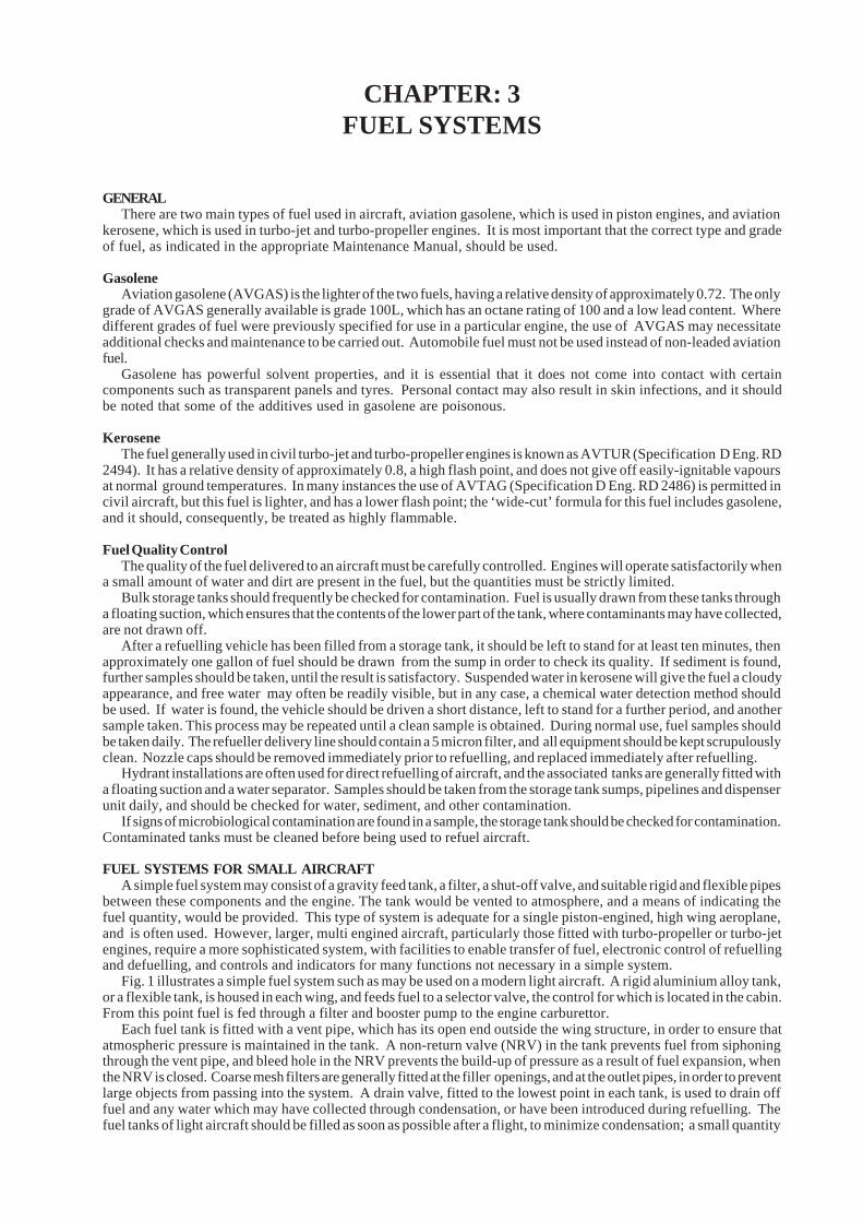
39Airframe and Aircraft Components
CHAPTER: 3FUEL SYSTEMS
GENERALThere are two main types of fuel used in aircraft, aviation gasolene, which is used in piston engines, and aviation
kerosene, which is used in turbo-jet and turbo-propeller engines. It is most important that the correct type and gradeof fuel, as indicated in the appropriate Maintenance Manual, should be used.
GasoleneAviation gasolene (AVGAS) is the lighter of the two fuels, having a relative density of approximately 0.72. The only
grade of AVGAS generally available is grade 100L, which has an octane rating of 100 and a low lead content. Wheredifferent grades of fuel were previously specified for use in a particular engine, the use of AVGAS may necessitateadditional checks and maintenance to be carried out. Automobile fuel must not be used instead of non-leaded aviationfuel.
Gasolene has powerful solvent properties, and it is essential that it does not come into contact with certaincomponents such as transparent panels and tyres. Personal contact may also result in skin infections, and it shouldbe noted that some of the additives used in gasolene are poisonous.
KeroseneThe fuel generally used in civil turbo-jet and turbo-propeller engines is known as AVTUR (Specification D Eng. RD
2494). It has a relative density of approximately 0.8, a high flash point, and does not give off easily-ignitable vapoursat normal ground temperatures. In many instances the use of AVTAG (Specification D Eng. RD 2486) is permitted incivil aircraft, but this fuel is lighter, and has a lower flash point; the ‘wide-cut’ formula for this fuel includes gasolene,and it should, consequently, be treated as highly flammable.
Fuel Quality ControlThe quality of the fuel delivered to an aircraft must be carefully controlled. Engines will operate satisfactorily when
a small amount of water and dirt are present in the fuel, but the quantities must be strictly limited.Bulk storage tanks should frequently be checked for contamination. Fuel is usually drawn from these tanks through
a floating suction, which ensures that the contents of the lower part of the tank, where contaminants may have collected,are not drawn off.
After a refuelling vehicle has been filled from a storage tank, it should be left to stand for at least ten minutes, thenapproximately one gallon of fuel should be drawn from the sump in order to check its quality. If sediment is found,further samples should be taken, until the result is satisfactory. Suspended water in kerosene will give the fuel a cloudyappearance, and free water may often be readily visible, but in any case, a chemical water detection method shouldbe used. If water is found, the vehicle should be driven a short distance, left to stand for a further period, and anothersample taken. This process may be repeated until a clean sample is obtained. During normal use, fuel samples shouldbe taken daily. The refueller delivery line should contain a 5 micron filter, and all equipment should be kept scrupulouslyclean. Nozzle caps should be removed immediately prior to refuelling, and replaced immediately after refuelling.
Hydrant installations are often used for direct refuelling of aircraft, and the associated tanks are generally fitted witha floating suction and a water separator. Samples should be taken from the storage tank sumps, pipelines and dispenserunit daily, and should be checked for water, sediment, and other contamination.
If signs of microbiological contamination are found in a sample, the storage tank should be checked for contamination.Contaminated tanks must be cleaned before being used to refuel aircraft.
FUEL SYSTEMS FOR SMALL AIRCRAFTA simple fuel system may consist of a gravity feed tank, a filter, a shut-off valve, and suitable rigid and flexible pipes
between these components and the engine. The tank would be vented to atmosphere, and a means of indicating thefuel quantity, would be provided. This type of system is adequate for a single piston-engined, high wing aeroplane,and is often used. However, larger, multi engined aircraft, particularly those fitted with turbo-propeller or turbo-jetengines, require a more sophisticated system, with facilities to enable transfer of fuel, electronic control of refuellingand defuelling, and controls and indicators for many functions not necessary in a simple system.
Fig. 1 illustrates a simple fuel system such as may be used on a modern light aircraft. A rigid aluminium alloy tank,or a flexible tank, is housed in each wing, and feeds fuel to a selector valve, the control for which is located in the cabin.From this point fuel is fed through a filter and booster pump to the engine carburettor.
Each fuel tank is fitted with a vent pipe, which has its open end outside the wing structure, in order to ensure thatatmospheric pressure is maintained in the tank. A non-return valve (NRV) in the tank prevents fuel from siphoningthrough the vent pipe, and bleed hole in the NRV prevents the build-up of pressure as a result of fuel expansion, whenthe NRV is closed. Coarse mesh filters are generally fitted at the filler openings, and at the outlet pipes, in order to preventlarge objects from passing into the system. A drain valve, fitted to the lowest point in each tank, is used to drain offfuel and any water which may have collected through condensation, or have been introduced during refuelling. Thefuel tanks of light aircraft should be filled as soon as possible after a flight, to minimize condensation; a small quantity
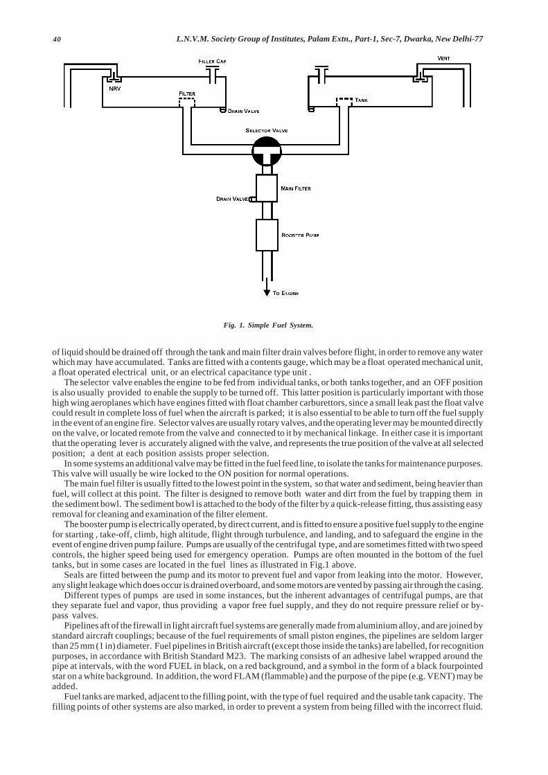
40 L.N.V.M. Society Group of Institutes, Palam Extn., Part-1, Sec-7, Dwarka, New Delhi-77
of liquid should be drained off through the tank and main filter drain valves before flight, in order to remove any waterwhich may have accumulated. Tanks are fitted with a contents gauge, which may be a float operated mechanical unit,a float operated electrical unit, or an electrical capacitance type unit .
The selector valve enables the engine to be fed from individual tanks, or both tanks together, and an OFF positionis also usually provided to enable the supply to be turned off. This latter position is particularly important with thosehigh wing aeroplanes which have engines fitted with float chamber carburettors, since a small leak past the float valvecould result in complete loss of fuel when the aircraft is parked; it is also essential to be able to turn off the fuel supplyin the event of an engine fire. Selector valves are usually rotary valves, and the operating lever may be mounted directlyon the valve, or located remote from the valve and connected to it by mechanical linkage. In either case it is importantthat the operating lever is accurately aligned with the valve, and represents the true position of the valve at all selectedposition; a dent at each position assists proper selection.
In some systems an additional valve may be fitted in the fuel feed line, to isolate the tanks for maintenance purposes.This valve will usually be wire locked to the ON position for normal operations.
The main fuel filter is usually fitted to the lowest point in the system, so that water and sediment, being heavier thanfuel, will collect at this point. The filter is designed to remove both water and dirt from the fuel by trapping them inthe sediment bowl. The sediment bowl is attached to the body of the filter by a quick-release fitting, thus assisting easyremoval for cleaning and examination of the filter element.
The booster pump is electrically operated, by direct current, and is fitted to ensure a positive fuel supply to the enginefor starting , take-off, climb, high altitude, flight through turbulence, and landing, and to safeguard the engine in theevent of engine driven pump failure. Pumps are usually of the centrifugal type, and are sometimes fitted with two speedcontrols, the higher speed being used for emergency operation. Pumps are often mounted in the bottom of the fueltanks, but in some cases are located in the fuel lines as illustrated in Fig.1 above.
Seals are fitted between the pump and its motor to prevent fuel and vapor from leaking into the motor. However,any slight leakage which does occur is drained overboard, and some motors are vented by passing air through the casing.
Different types of pumps are used in some instances, but the inherent advantages of centrifugal pumps, are thatthey separate fuel and vapor, thus providing a vapor free fuel supply, and they do not require pressure relief or by-pass valves.
Pipelines aft of the firewall in light aircraft fuel systems are generally made from aluminium alloy, and are joined bystandard aircraft couplings; because of the fuel requirements of small piston engines, the pipelines are seldom largerthan 25 mm (1 in) diameter. Fuel pipelines in British aircraft (except those inside the tanks) are labelled, for recognitionpurposes, in accordance with British Standard M23. The marking consists of an adhesive label wrapped around thepipe at intervals, with the word FUEL in black, on a red background, and a symbol in the form of a black fourpointedstar on a white background. In addition, the word FLAM (flammable) and the purpose of the pipe (e.g. VENT) may beadded.
Fuel tanks are marked, adjacent to the filling point, with the type of fuel required and the usable tank capacity. Thefilling points of other systems are also marked, in order to prevent a system from being filled with the incorrect fluid.
Fig.1. Simple Fuel System.
Fig. 1. Simple Fuel System.
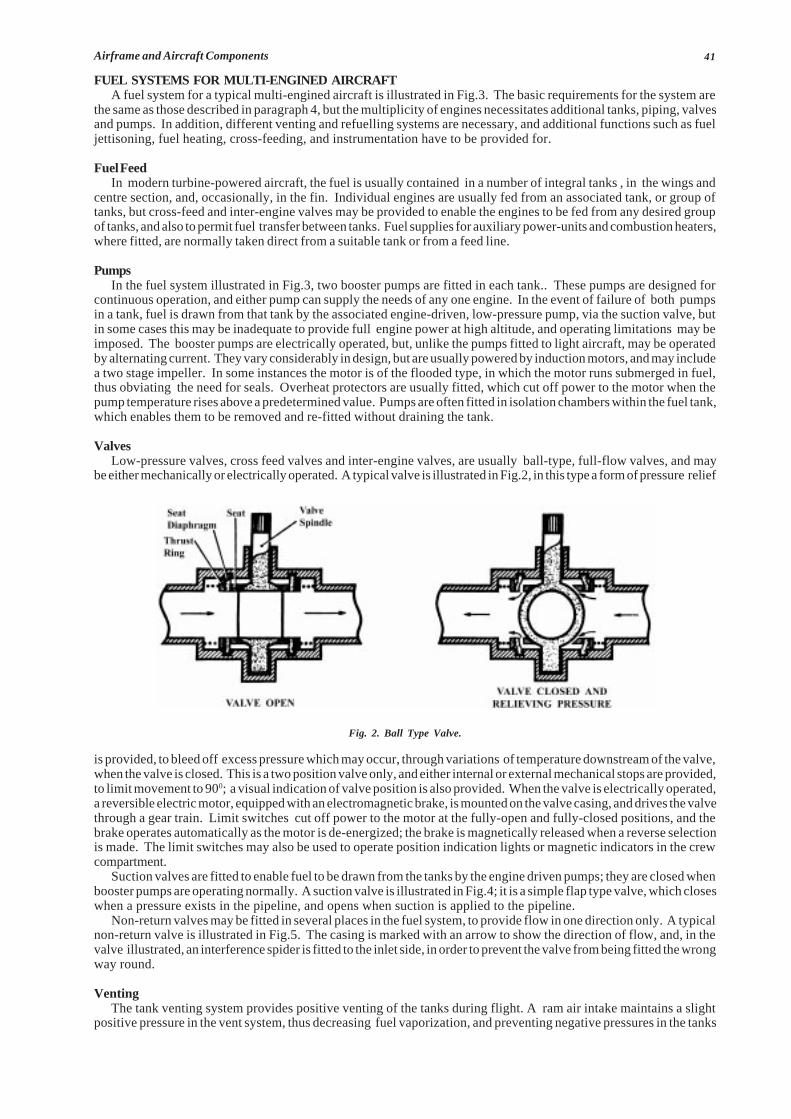
41Airframe and Aircraft Components
FUEL SYSTEMS FOR MULTI-ENGINED AIRCRAFTA fuel system for a typical multi-engined aircraft is illustrated in Fig.3. The basic requirements for the system are
the same as those described in paragraph 4, but the multiplicity of engines necessitates additional tanks, piping, valvesand pumps. In addition, different venting and refuelling systems are necessary, and additional functions such as fueljettisoning, fuel heating, cross-feeding, and instrumentation have to be provided for.
Fuel FeedIn modern turbine-powered aircraft, the fuel is usually contained in a number of integral tanks , in the wings and
centre section, and, occasionally, in the fin. Individual engines are usually fed from an associated tank, or group oftanks, but cross-feed and inter-engine valves may be provided to enable the engines to be fed from any desired groupof tanks, and also to permit fuel transfer between tanks. Fuel supplies for auxiliary power-units and combustion heaters,where fitted, are normally taken direct from a suitable tank or from a feed line.
PumpsIn the fuel system illustrated in Fig.3, two booster pumps are fitted in each tank.. These pumps are designed for
continuous operation, and either pump can supply the needs of any one engine. In the event of failure of both pumpsin a tank, fuel is drawn from that tank by the associated engine-driven, low-pressure pump, via the suction valve, butin some cases this may be inadequate to provide full engine power at high altitude, and operating limitations may beimposed. The booster pumps are electrically operated, but, unlike the pumps fitted to light aircraft, may be operatedby alternating current. They vary considerably in design, but are usually powered by induction motors, and may includea two stage impeller. In some instances the motor is of the flooded type, in which the motor runs submerged in fuel,thus obviating the need for seals. Overheat protectors are usually fitted, which cut off power to the motor when thepump temperature rises above a predetermined value. Pumps are often fitted in isolation chambers within the fuel tank,which enables them to be removed and re-fitted without draining the tank.
ValvesLow-pressure valves, cross feed valves and inter-engine valves, are usually ball-type, full-flow valves, and may
be either mechanically or electrically operated. A typical valve is illustrated in Fig.2, in this type a form of pressure relief
Fig. 2. Ball Type Valve.
is provided, to bleed off excess pressure which may occur, through variations of temperature downstream of the valve,when the valve is closed. This is a two position valve only, and either internal or external mechanical stops are provided,to limit movement to 900; a visual indication of valve position is also provided. When the valve is electrically operated,a reversible electric motor, equipped with an electromagnetic brake, is mounted on the valve casing, and drives the valvethrough a gear train. Limit switches cut off power to the motor at the fully-open and fully-closed positions, and thebrake operates automatically as the motor is de-energized; the brake is magnetically released when a reverse selectionis made. The limit switches may also be used to operate position indication lights or magnetic indicators in the crewcompartment.
Suction valves are fitted to enable fuel to be drawn from the tanks by the engine driven pumps; they are closed whenbooster pumps are operating normally. A suction valve is illustrated in Fig.4; it is a simple flap type valve, which closeswhen a pressure exists in the pipeline, and opens when suction is applied to the pipeline.
Non-return valves may be fitted in several places in the fuel system, to provide flow in one direction only. A typicalnon-return valve is illustrated in Fig.5. The casing is marked with an arrow to show the direction of flow, and, in thevalve illustrated, an interference spider is fitted to the inlet side, in order to prevent the valve from being fitted the wrongway round.
VentingThe tank venting system provides positive venting of the tanks during flight. A ram air intake maintains a slight
positive pressure in the vent system, thus decreasing fuel vaporization, and preventing negative pressures in the tanks
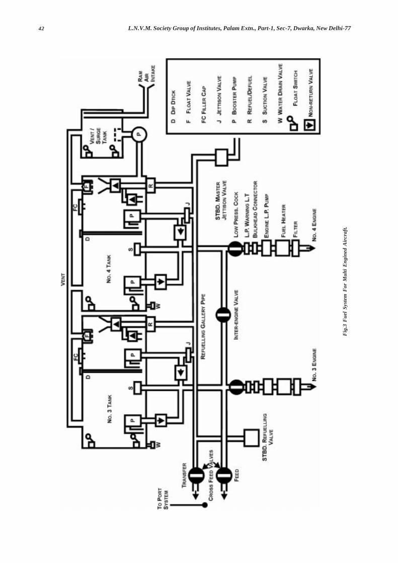
42 L.N.V.M. Society Group of Institutes, Palam Extn., Part-1, Sec-7, Dwarka, New Delhi-77
Fig
.3 F
uel
Sys
tem
For
Mul
ti E
ngin
ed A
ircr
aft.
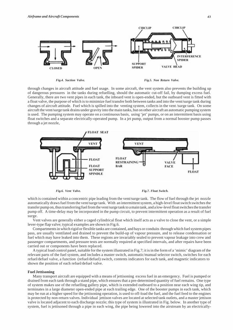
43Airframe and Aircraft Components
Fig.4. Suction Valve. Fig.5. Non Return Valve.
through changes in aircraft attitude and fuel usage. In some aircraft, the vent system also prevents the building upof dangerous pressures in the tanks during refuelling, should the automatic cut-off fail, by dumping excess fuel.Generally, there are two vent pipes in each tank, the inboard vent is open-ended, but the outboard vent is fitted witha float valve, the purpose of which is to minimize fuel transfer both between tanks and into the vent/surge tank duringchanges of aircraft attitude. Fuel which is spilled into the venting system, collects in the vent /surge tank. On someaircraft the vent/surge tank drains under gravity into the main tanks, but on other aircraft an automatic pumping systemis used. The pumping system may operate on a continuous basis, using ‘jet’ pumps, or on an intermittent basis usingfloat switches and a separate electrically-operated pump. In a jet pump, output from a normal booster pump passesthrough a jet nozzle,
Fig.6. Vent Valve. Fig.7. Float Switch.
which is contained within a concentric pipe leading from the vent/surge tank. The flow of fuel through the jet nozzleautomatically draws fuel from the vent/surge tank. With an intermittent system, a high-level float switch switches thetransfer pump on, thus transferring fuel from the vent/surge tank to a main tank, and a low-level float switches the transferpump off. A time-delay may be incorporated in the pump circuit, to prevent intermittent operation as a result of fuelsurge.
Vent valves are generally either a caged cylindrical float which itself acts as a valve to close the vent, or a simplelever-type flap valve; typical examples are shown in Fig.6.
Compartments in which rigid or flexible tanks are contained, and bays or conduits through which fuel system pipespass, are usually ventilated and drained to prevent the build-up of vapour pressure, and to release condensation orfuel which may have leaked into them. These regions are invariably sealed to prevent vapour leakage into crew andpassenger compartments, and pressure tests are normally required at specified intervals, and after repairs have beencarried out or components have been replaced.
A typical load control panel, suitable for the system illustrated in Fig.7; it is in the form of a ‘mimic’ diagram of therelevant parts of the fuel system, and includes a master switch, automatic/manual selector switch, switches for eachrefuel/defuel valve, a function (refuel/defuel) switch, contents indicators for each tank, and magnetic indicators toshown the position of each refuel/defuel valve.
Fuel JettisoningMany transport aircraft are equipped with a means of jettisoning excess fuel in an emergency. Fuel is pumped or
drained from each tank through a stand pipe, which ensures that a pre-determined quantity of fuel remains. One typeof system makes use of the refuelling gallery pipe, which is extended outboard to a position near each wing tip, andterminates in a large diameter open-ended pipe at each trailing edge. One of the booster pumps in each tank, whichmay be run at a higher speed for the jettisoning operation, is used to off-load the fuel, and the fuel feed to the enginesis protected by non-return valves. Individual jettison valves are located at selected tank outlets, and a master jettisonvalve is located adjacent to each discharge nozzle; this type of system is illustrated in Fig. below. In another type ofsystem, fuel is jettisoned through a pipe in each wing, the pipe being lowered into the airstream by an electrically-
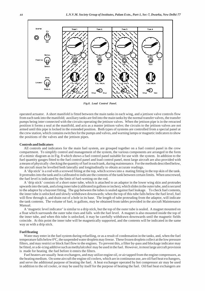
44 L.N.V.M. Society Group of Institutes, Palam Extn., Part-1, Sec-7, Dwarka, New Delhi-77
operated actuator. A short manifold is fitted between the main tanks in each wing, and a jettison valve controls flowfrom each tank into the manifold; auxiliary tanks are fed into the main tanks by the normal transfer valves, the transferpumps being inter connected with the circuits operating the jettison valves. When the jettison pipe is in the retractedposition it forms a seal at the manifold, and acts as a master jettison valve; the circuits to the jettison valves are notarmed until this pipe is locked in the extended position. Both types of systems are controlled from a special panel atthe crew station, which contains switches for the pumps and valves, and warning lamps or magnetic indicators to showthe positions of the valves and the jettison pipes.
Controls and IndicatorsAll controls and indicators for the main fuel system, are grouped together on a fuel control panel in the crew
compartment. To simplify control and management of the system, the various components are arranged in the formof a mimic diagram as in Fig. 8 which shows a fuel control panel suitable for use with the system. In addition to thefuel quantity gauges fitted to the fuel control panel and load control panel, most large aircraft are also provided witha means of physically checking the quantity of fuel in each tank, during maintenance. For the methods described below,the aircraft must be levelled both laterally and longitudinally to obtain accurate readings.
A ‘dip stick’ is a rod with a screwed fitting at the top, which screws into a mating fitting in the top skin of the tank.It protrudes into the tank and is calibrated to indicate the contents of the tank between certain limits. When unscrewed,the fuel level is indicated by the limit of fuel-wetting on the rod.
A ‘drip stick’ consists of a short outer tube, which is attached to an adaptor in the lower wing skin and protrudesupwards into the tank, and a long inner tube (calibrated in gallons or inches), which slides in the outer tube, and is securedto the adaptor by a bayonet fitting. The gap between the tubes is sealed against fuel leakage. To check fuel contents,the inner tube is unlocked and slowly withdrawn downwards; when the top of this tube falls below the fuel level, fuelwill flow through it, and drain out of a hole in its base. The length of tube protruding from the adaptor, will indicatethe tank contents. The volume of fuel, in gallons, may be obtained from tables provided in the aircraft MaintenanceManual.
A ‘magnetic level indicator’ is similar to a drip stick, but the top of the outer tube is sealed. A magnet mounted ona float which surrounds the outer tube rises and falls with the fuel level. A magnet is also mounted inside the top ofthe inner tube, and when this tube is unlocked, it may be carefully withdrawn downwards until the magnetic fieldscoincide. At this point the inner tube will be magnetically supported, and the contents will be indicated in the sameway as with a drip stick.
Fuel HeatingWater may enter in the fuel system during refuelling, or as a result of condensation in the tanks, and, when the fuel
temperature falls below 00C, the suspended water droplets may freeze. These frozen droplets collect at the low pressurefilters, and may restrict or block fuel flow to the engines. To prevent this, a filter by-pass and blockage indicator maybe fitted, or a de-icing additive such as methylalcohol may be used in the fuel. However, in most large aircraft provisionis made for heating the fuel before it enters the filters.
Fuel heaters are usually heat-exchangers, and may utilize engine oil, or air tapped from the engine compressors, asthe heating medium. On some aircraft the engine oil coolers, which are in continuous use, are oil/fuel heat exchangers,and serve the additional purpose of heating the fuel. A heat exchanger operated by hot compressor air may be usedin addition to the oil cooler, or may be used by itself for the purpose of heating the fuel. Oil/fuel heat exchangers are
Fig.8. Load Control Panel.
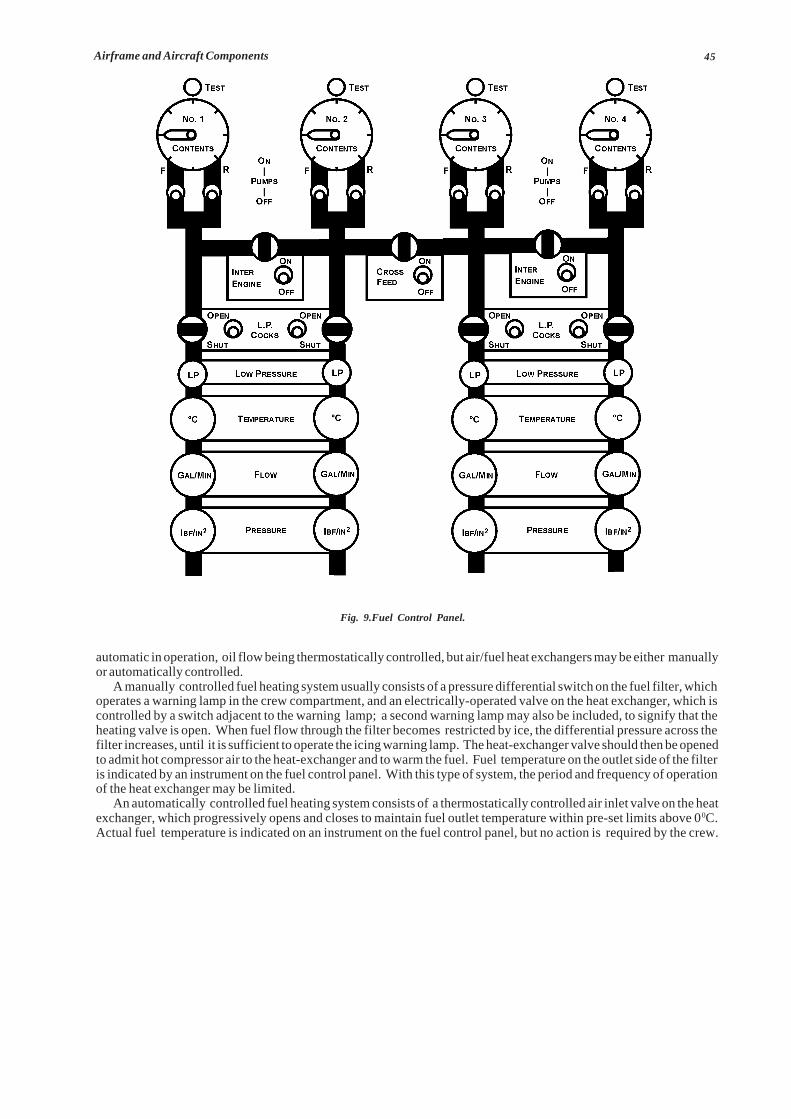
45Airframe and Aircraft Components
automatic in operation, oil flow being thermostatically controlled, but air/fuel heat exchangers may be either manuallyor automatically controlled.
A manually controlled fuel heating system usually consists of a pressure differential switch on the fuel filter, whichoperates a warning lamp in the crew compartment, and an electrically-operated valve on the heat exchanger, which iscontrolled by a switch adjacent to the warning lamp; a second warning lamp may also be included, to signify that theheating valve is open. When fuel flow through the filter becomes restricted by ice, the differential pressure across thefilter increases, until it is sufficient to operate the icing warning lamp. The heat-exchanger valve should then be openedto admit hot compressor air to the heat-exchanger and to warm the fuel. Fuel temperature on the outlet side of the filteris indicated by an instrument on the fuel control panel. With this type of system, the period and frequency of operationof the heat exchanger may be limited.
An automatically controlled fuel heating system consists of a thermostatically controlled air inlet valve on the heatexchanger, which progressively opens and closes to maintain fuel outlet temperature within pre-set limits above 00C.Actual fuel temperature is indicated on an instrument on the fuel control panel, but no action is required by the crew.
� � �
Fig. 9.Fuel Control Panel.
46 L.N.V.M. Society Group of Institutes, Palam Extn., Part-1, Sec-7, Dwarka, New Delhi-77
CHAPTER: 4PNEUMATIC SYSTEMS
PNEUMATIC SYSTEMSThe use of a compressed-air system to operate an aircraft’s services usually represents a saving in weight compared
to a hydraulic system, since the operating medium is freely available, no return lines are necessary, and pipes can besmaller diameter. Systems having operating pressures of up to 24 MN/m2 are in use, and provide for the rapid operationof services when this is required. However, compressed air is generally not suitable for the operation of large capacitycomponents, leaks can be difficult to trace, and the results of pipeline or component failure can be very serious.
Extensive high-pressure pneumatic systems powered by engine-driven compressors are generally fitted on the oldertypes of piston-engined aircraft and are used to operate services such as the landing gear, wing flaps, wheel brakes,radiator shutters and, at reduced pressure, de-icing shoes. There are some modern aircraft which also use a high-pressure pneumatic system, however, and there are many aircraft which use pneumatic power for the emergencyoperation of essential services; the latter type of system is usually designed for ground-charging only.
Low-pressure pneumatic systems such as are used on most turbine-engined aircraft for engine starting, de-icing,and cabin pressurization, are supplied with compressed air tapped from the engine compressor.
TYPICAL SYSTEMThis paragraph describes both a typical high-pressure pneumatic system, and the types of components which could
be used.The system illustrated in Fig.1 contains two separate power circuits, each of which is supplied by a four-stage
compressor driven from the gearbox of one main engine, and a common delivery pipe to the high-presser storage bottlesand system services. A multi-stage cooler attached to each compressor cools the air between each of the compressionstages, and a means is provided for off-loading the compressor when the system is not being used.
Air is drawn through an inlet filter into each compressor, and is discharged through an oil-and-water trap, a chemicaldehydrator, a filter and a non-return valve, to the main storage bottle and system. Overall control of main system pressureis provided by means of a pressure regulator, but pressure relief valves are included to prevent excessive pressuresin the system, which may be caused by regulator failure or by an increase in temperature in the pipelines and components.Pressure reducing valves are used to reduce the pressure supplied to some components.
A storage bottle for the emergency system is pressurized through a non-return valve from the main system supply,and maintains an adequate supply of compressed air to enable the landing gear and flaps to be lowered, and the brakesto be applied a sufficient number of times to ensure a safe landing.
Isolation valves are fitted to enable servicing and maintenance to be carried out without the need to release all airfrom the system, and pressure gauges are provided to indicate the air pressure in the main and emergency storagebottles.
COMPONENTSThe types of components used in a high-pressure pneumatic system will vary considerably between aircraft, but
the examples considered in this paragraph are typical of the components which may be found in current use.
CompressorsA positive-displacement pump is necessary to raise the air pressure sufficiently for the operation of a pneumatic
system, and a piston-type pump is generally used. Some older types of aircraft are fitted with a single-cylinder pistonpump, which provides two stages of compression and raises the working pressure to approximately 3MN/m2 (450 1bf/in2). To obtain higher working pressures further compression stages are required.
The compressor illustrated in Fig. 2 has two stepped cylinders, each of which houses a stepped piston; a plungerattached to the head of No. 2 cylinder. The reciprocating motion of the main pistons is provided by individual cranksand connecting rods, the cranks being rotated by a common drive gear, and rotating in the same direction. Air passingbetween each compression stage is routed through an integral cooler, and lubrication is provided by an oil feedconnection from the main engine lubrication system.
Compression depends on the volume of each successive stroke being smaller than the stroke preceding it; theinduction strokes for each cylinder and the four compression strokes are accomplished during each revolution of thecranks. Operation of the compressor is as follows :-
(a) On the downward stroke of No.1 piston, air is drawn into the cylinder head through a filter and non-returnvalve (NRV).
(b) On the upward stroke of No. 1 piston, air is compressed in the cylinder, opens a NRV in the cylinder head,and passes to the annular space formed between the steps of the cylinder and piston.
(c) The next downward stroke of No. 1 piston compresses air in the annular space in this cylinder and forcesit through a NRV into the annular space formed between the steps of No. 2 cylinder and piston. No. 2 pistonis approximately 900 in advance of No. 1 piston, and is moving upwards as No. 1 piston approaches the bottomof its stroke.
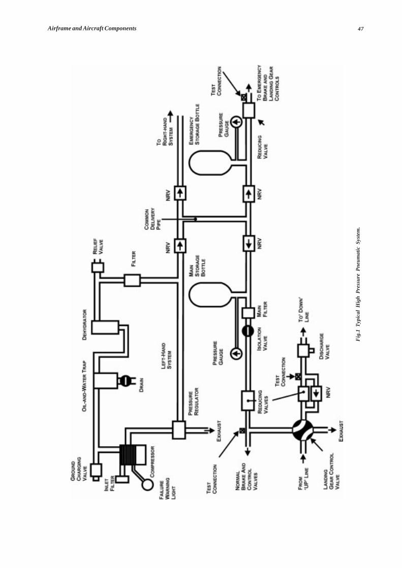
47Airframe and Aircraft Components
Fig
.1 T
ypic
al H
igh
Pre
ssur
e P
neum
atic
Sys
tem
.
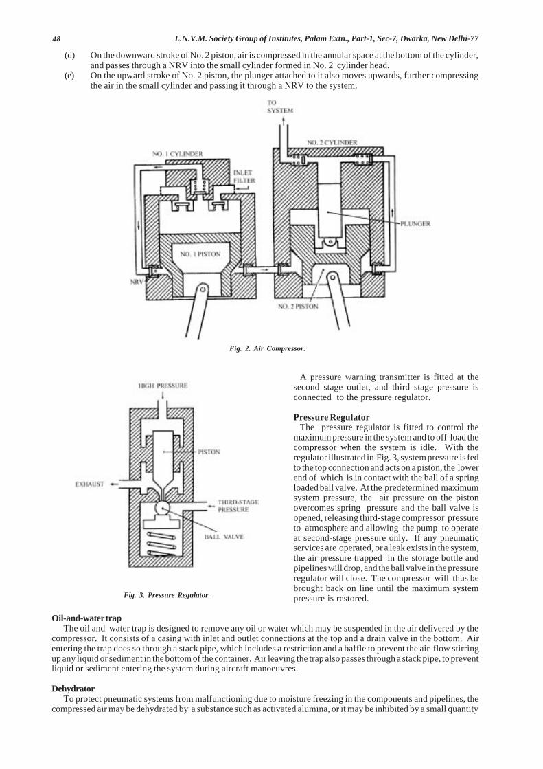
48 L.N.V.M. Society Group of Institutes, Palam Extn., Part-1, Sec-7, Dwarka, New Delhi-77
(d) On the downward stroke of No. 2 piston, air is compressed in the annular space at the bottom of the cylinder,and passes through a NRV into the small cylinder formed in No. 2 cylinder head.
(e) On the upward stroke of No. 2 piston, the plunger attached to it also moves upwards, further compressingthe air in the small cylinder and passing it through a NRV to the system.
A pressure warning transmitter is fitted at thesecond stage outlet, and third stage pressure isconnected to the pressure regulator.
Pressure RegulatorThe pressure regulator is fitted to control the
maximum pressure in the system and to off-load thecompressor when the system is idle. With theregulator illustrated in Fig. 3, system pressure is fedto the top connection and acts on a piston, the lowerend of which is in contact with the ball of a springloaded ball valve. At the predetermined maximumsystem pressure, the air pressure on the pistonovercomes spring pressure and the ball valve isopened, releasing third-stage compressor pressureto atmosphere and allowing the pump to operateat second-stage pressure only. If any pneumaticservices are operated, or a leak exists in the system,the air pressure trapped in the storage bottle andpipelines will drop, and the ball valve in the pressureregulator will close. The compressor will thus bebrought back on line until the maximum systempressure is restored.
Oil-and-water trapThe oil and water trap is designed to remove any oil or water which may be suspended in the air delivered by the
compressor. It consists of a casing with inlet and outlet connections at the top and a drain valve in the bottom. Airentering the trap does so through a stack pipe, which includes a restriction and a baffle to prevent the air flow stirringup any liquid or sediment in the bottom of the container. Air leaving the trap also passes through a stack pipe, to preventliquid or sediment entering the system during aircraft manoeuvres.
DehydratorTo protect pneumatic systems from malfunctioning due to moisture freezing in the components and pipelines, the
compressed air may be dehydrated by a substance such as activated alumina, or it may be inhibited by a small quantity
Fig. 3. Pressure Regulator.
Fig. 2. Air Compressor.
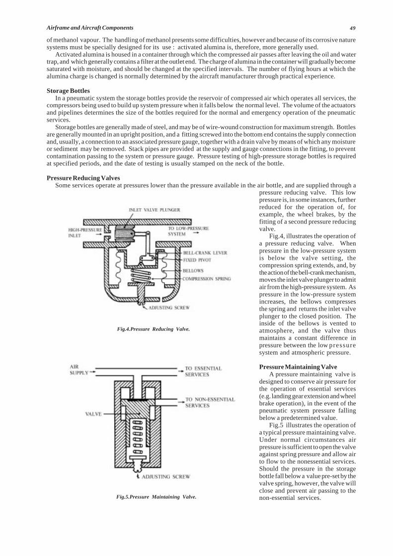
49Airframe and Aircraft Components
of methanol vapour. The handling of methanol presents some difficulties, however and because of its corrosive naturesystems must be specially designed for its use : activated alumina is, therefore, more generally used.
Activated alumina is housed in a container through which the compressed air passes after leaving the oil and watertrap, and which generally contains a filter at the outlet end. The charge of alumina in the container will gradually becomesaturated with moisture, and should be changed at the specified intervals. The number of flying hours at which thealumina charge is changed is normally determined by the aircraft manufacturer through practical experience.
Storage BottlesIn a pneumatic system the storage bottles provide the reservoir of compressed air which operates all services, the
compressors being used to build up system pressure when it falls below the normal level. The volume of the actuatorsand pipelines determines the size of the bottles required for the normal and emergency operation of the pneumaticservices.
Storage bottles are generally made of steel, and may be of wire-wound construction for maximum strength. Bottlesare generally mounted in an upright position, and a fitting screwed into the bottom end contains the supply connectionand, usually, a connection to an associated pressure gauge, together with a drain valve by means of which any moistureor sediment may be removed. Stack pipes are provided at the supply and gauge connections in the fitting, to preventcontamination passing to the system or pressure gauge. Pressure testing of high-pressure storage bottles is requiredat specified periods, and the date of testing is usually stamped on the neck of the bottle.
Pressure Reducing ValvesSome services operate at pressures lower than the pressure available in the air bottle, and are supplied through a
pressure reducing valve. This lowpressure is, in some instances, furtherreduced for the operation of, forexample, the wheel brakes, by thefitting of a second pressure reducingvalve.
Fig.4, illustrates the operation ofa pressure reducing valve. Whenpressure in the low-pressure systemis below the valve setting, thecompression spring extends, and, bythe action of the bell-crank mechanism,moves the inlet valve plunger to admitair from the high-pressure system. Aspressure in the low-pressure systemincreases, the bellows compressesthe spring and returns the inlet valveplunger to the closed position. Theinside of the bellows is vented toatmosphere, and the valve thusmaintains a constant difference inpressure between the lowpressuresystem and atmospheric pressure.
Pressure Maintaining ValveA pressure maintaining valve is
designed to conserve air pressure forthe operation of essential services(e.g. landing gear extension and wheelbrake operation), in the event of thepneumatic system pressure fallingbelow a predetermined value.
Fig.5 illustrates the operation ofa typical pressure maintaining valve.Under normal circumstances airpressure is sufficient to open the valveagainst spring pressure and allow airto flow to the nonessential services.Should the pressure in the storagebottle fall below a value pre-set by thevalve spring, however, the valve willclose and prevent air passing to thenon-essential services.Fig.5.Pressure Maintaining Valve.
Fig.4.Pressure Reducing Valve.
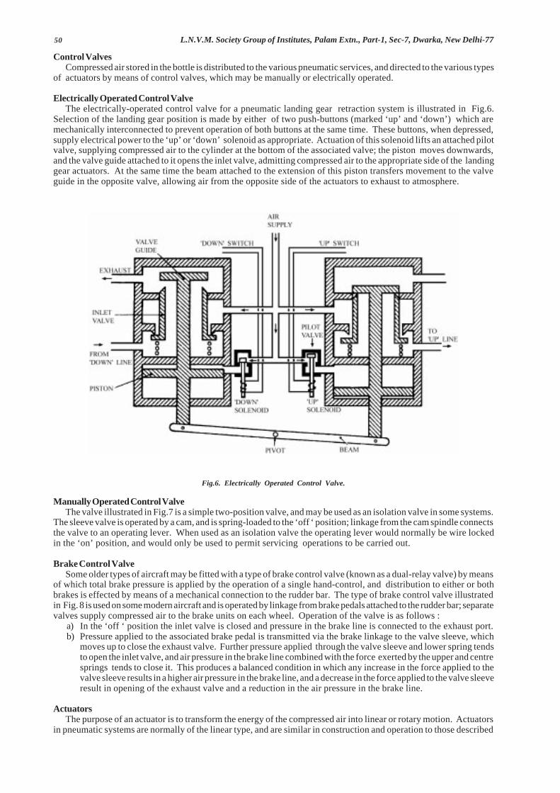
50 L.N.V.M. Society Group of Institutes, Palam Extn., Part-1, Sec-7, Dwarka, New Delhi-77
Control ValvesCompressed air stored in the bottle is distributed to the various pneumatic services, and directed to the various types
of actuators by means of control valves, which may be manually or electrically operated.
Electrically Operated Control ValveThe electrically-operated control valve for a pneumatic landing gear retraction system is illustrated in Fig.6.
Selection of the landing gear position is made by either of two push-buttons (marked ‘up’ and ‘down’) which aremechanically interconnected to prevent operation of both buttons at the same time. These buttons, when depressed,supply electrical power to the ‘up’ or ‘down’ solenoid as appropriate. Actuation of this solenoid lifts an attached pilotvalve, supplying compressed air to the cylinder at the bottom of the associated valve; the piston moves downwards,and the valve guide attached to it opens the inlet valve, admitting compressed air to the appropriate side of the landinggear actuators. At the same time the beam attached to the extension of this piston transfers movement to the valveguide in the opposite valve, allowing air from the opposite side of the actuators to exhaust to atmosphere.
Fig.6. Electrically Operated Control Valve.
Manually Operated Control ValveThe valve illustrated in Fig.7 is a simple two-position valve, and may be used as an isolation valve in some systems.
The sleeve valve is operated by a cam, and is spring-loaded to the ‘off ‘ position; linkage from the cam spindle connectsthe valve to an operating lever. When used as an isolation valve the operating lever would normally be wire lockedin the ‘on’ position, and would only be used to permit servicing operations to be carried out.
Brake Control ValveSome older types of aircraft may be fitted with a type of brake control valve (known as a dual-relay valve) by means
of which total brake pressure is applied by the operation of a single hand-control, and distribution to either or bothbrakes is effected by means of a mechanical connection to the rudder bar. The type of brake control valve illustratedin Fig. 8 is used on some modern aircraft and is operated by linkage from brake pedals attached to the rudder bar; separatevalves supply compressed air to the brake units on each wheel. Operation of the valve is as follows :
a) In the ‘off ‘ position the inlet valve is closed and pressure in the brake line is connected to the exhaust port.b) Pressure applied to the associated brake pedal is transmitted via the brake linkage to the valve sleeve, which
moves up to close the exhaust valve. Further pressure applied through the valve sleeve and lower spring tendsto open the inlet valve, and air pressure in the brake line combined with the force exerted by the upper and centresprings tends to close it. This produces a balanced condition in which any increase in the force applied to thevalve sleeve results in a higher air pressure in the brake line, and a decrease in the force applied to the valve sleeveresult in opening of the exhaust valve and a reduction in the air pressure in the brake line.
ActuatorsThe purpose of an actuator is to transform the energy of the compressed air into linear or rotary motion. Actuators
in pneumatic systems are normally of the linear type, and are similar in construction and operation to those described
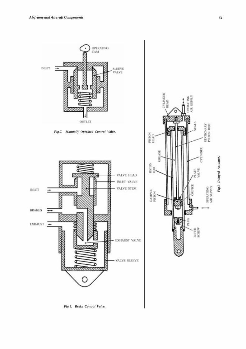
51Airframe and Aircraft Components
Fig.7. Manually Operated Control Valve.
Fig.8. Brake Control Valve.
Fig
.9 D
am
pe
d A
ctu
ato
r.

52 L.N.V.M. Society Group of Institutes, Palam Extn., Part-1, Sec-7, Dwarka, New Delhi-77
in before for hydraulic system. Because of the nature of the operating medium, however, actuators in pneumatic systemsare often damped to prevent violent operation of the service. A typical damped actuator is illustrated in Fig. 9 thedamping in this case being obtained by forcing grease through the annular space between the inner wall of the pistonrod and a stationary damper piston : an orifice and plate valve in the damper piston provide less damping action whenthe piston rod retracts than when it extends. This type of actuator could be used, for example, to operate the landinggear and to restrict the rate of extension.
� � �
53Airframe and Aircraft Components
CHAPTER: 5AIR CONDITIONING
GENERALThe air conditioning system of an aircraft is designed to maintain selected temperature conditions within flight crew,
passengers and either compartments, and comprises five principle sections: air supply, heating, cooling, temperaturecontrol, and distribution. In some aircraft humidity control section also forms part of the air conditioning system.
In pressurised aircraft, the air conditioning and pressure installation systems are intrinsically linked, and it is thecontrolled discharge of pressurised and conditioned air, which maintains the elected cabin altitude. For furtherinformation on aircraft pressurisation systems and cabin pressure control equipment.
Brief descriptions of some principal units which form a typical air conditioning system are given in the relevant airconditioning cycles. Basically two types of Air conditioning cycles are used.(I) Air cycle system (II) Vapour cycle system.
I AIR CYCLE SYSYEMThere are two types of Air Cycle System:(1) Ram air system(2) Engine bleed air system
RAM AIR SYSTEM
AIR SUPPLYThis method is adopted in certain small types of unpressurised aircraft utilising either combustion heating or engine
exhaust heat exchanger systems. A typical system is diagrammatically illustrated in Fig.1. Typical location for ram airintake are at the nose of an aircraft or in a dorsal fairing at the base of the fin or vertical stabiliser. The air after circulatingthrough the cabin, is discharged to atmosphere via a spill vent.
HEATINGThe method of heating the air depends on the type of air supply system and one of the methods outlined in the
following paragraphs may be adopted.
Combustion heatingThis method is normally associated with a direct type of ram air ventilating system, and depends for its operation
on the combustion of a fuel and air mixture within a special cylindrical combustion chamber (Fig.1).Air for combustion is obtained from a blower and the fuel is metered from the aircraft fuel system by a solenoid-
operated control valve. A filter and safety valve are also incorporated in the fuel supply line to the combustion chamber.The fuel - air mixture is ignited by a spark plug, the burning gases travelling the length of the combustion chamber andpassing through transfer passages to an exhaust outlet. Ventilating air from the ram air intake passes through the heaterand is heated by contact with the outer surfaces of the combustion chamber.
Blower operation and supply of fuel is normally controlled by a single switch. Regulation of the cabin temperatureis carried out by the manual setting of a mechanically controlled switch installed in the ducting downstream of the heater.
Engine exhaust heatingThe method is also associated with ram air ventilating systems, but heating of the air supply is effected in a simpler
and more direct manner. Air enters through an intake connected to a heater muff which surrounds the exhaust pipe ofa piston engine exhaust system. After heating, the air passes into the cabin via a chamber through which cold air alsoflows from an intake situated either in the fuselage or in the wing depending on the installation. Mechanically operatedvalves are provided to control the mixing of the airflows and so regulate the temperature.
COOLINGIn ram air supply systems the cooling method is of the simplest type whereby the cold air can be directly admitted
to the cabin via adjustable louvres. In the more complex systems cooling may be accomplished by either the air cycleor the vapour cycle method.
TEMPERATURE CONTROLControl of air temperature conditions in passenger cabins, flight crew and other compartments, is accomplished by
modulating the valves installed in the air ducting of heating and cooling sections of the air conditioning system. Themethods of control vary and depend on the type of aircraft and the air conditioning system employed. In general, twoprincipal methods are adopted, mechanical and electromechanical. The information given on these two methods in thefollowing paragraph is of a general nature, and reference should always be made to specific Aircraft MaintenanceManuals for full operating details.
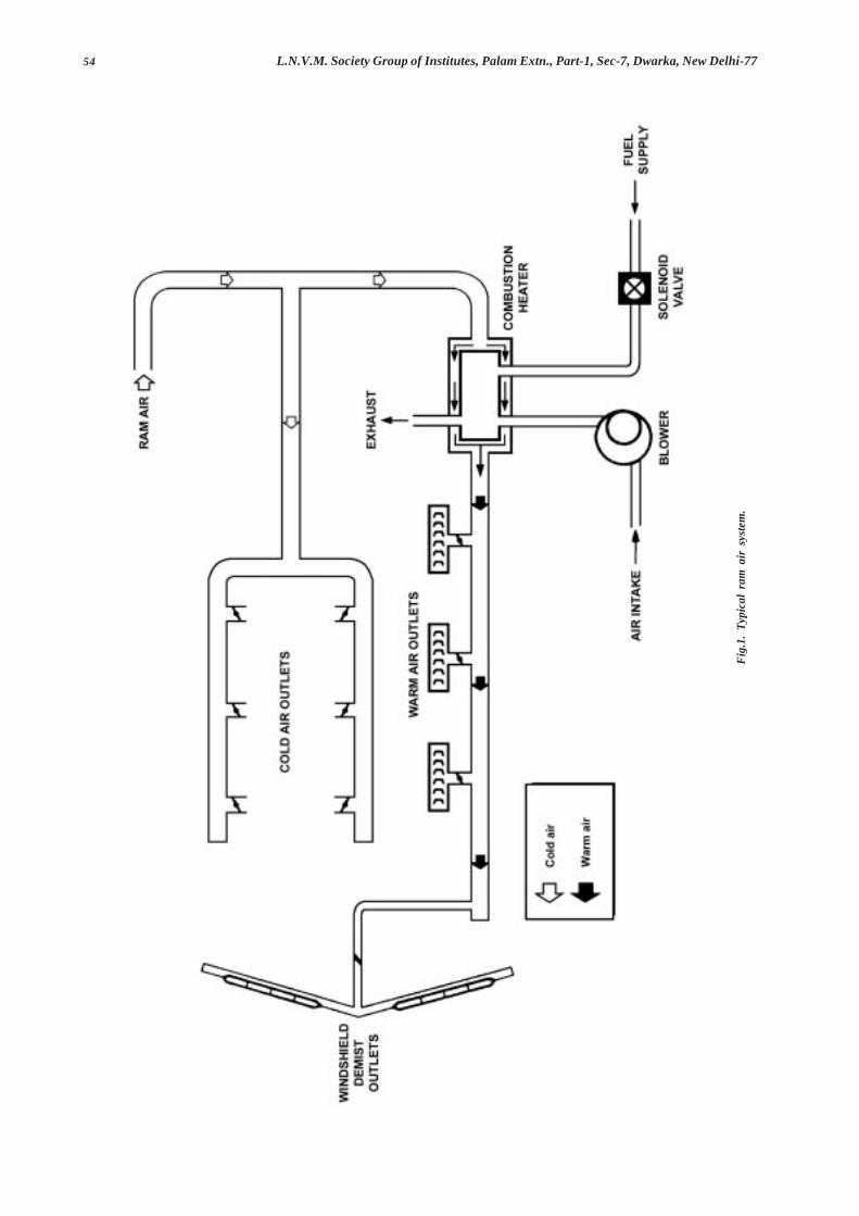
54 L.N.V.M. Society Group of Institutes, Palam Extn., Part-1, Sec-7, Dwarka, New Delhi-77
Fig
.1.
Typ
ical
ram
air
sys
tem
.
55Airframe and Aircraft Components
Mechanical controlOne mechanical method, which, for example, is employed in aircraft utilising an engine exhaust heating system, and
consists of valves which can be manually positioned to regulate the temperature by varying the proportions of hot andcold air passing through a mixing box before delivering it to the cabin. In some installations, hot and cold air entersthe cabin through separate valves and ducting.
Electromagnetic controlThe electromechanical method of temperature control used in some types of combustion heating system, is also
used in all air conditioning systems which utilise the compression method of heating, and air cycle or vapour cyclemethods of cooling. In a combustion heating system, the electrical power supply to the solenoid valve is automaticallycontrolled by the duct thermostat. When the temperature of the air flowing from the heater exceeds the thermostatsetting, the thermostat de-energises the solenoid valve to isolate the fuel supply to the heater. As the heater cools,the thermostat opens the valve to restore the fuel flow and combustion process. By cycling on and off, the heatermaintains an even temperature in the cabin.
ENGINE BLEED AIR SYSTEMThis method is adopted in certain types of turbojet aircraft, in which hot air, readily available from main engine
compressors is tapped off and supplied to the cabin. Before the air enters the cabin it is passed through appropriatecontrol valves and a temperature control system to reduce its pressure and temperature. A typical bleed air system ofthe ‘bootstrap’ type is illustrated diagrammatically in Fig.2.
AIR SUPPLY
Auxiliary power unit (APU)The auxiliary power unit, where fitted, is an independent source of pressurised air. Operation of the APU is , however,
subject to certain limitations. Fig.2 diagrammatically illustrates a typical system employing an auxiliary power unit.
Compressors or blowersThis method is utilised in some types of turbojet, turbo propeller and piston-engine aircraft, the compressors or
blowers being driven by the engines via accessory drives, gear boxes or bleed air. Fig.3 diagrammatically illustratesa typical system employing an air displacement type of blower.
Air is drawn in through a ram air intake located in a wing leading edge or an engine nacelle fairing. A filter unit maybe provided to protect the blower rotors from foreign matter and to ensure a clean air supply. In order a reduce the levelof noise emanating from the blower, silencers are incorporated in the main supply ducting.
HEATINGEngine bleed air system employs compression heating. This system of heating relies on the principle whereby the
air temperature is increased by compression and forms the basis of the heating method employed air supply systemutilising engine driven compressors or engine bleed air.
COOLINGThe operation of an air cycle cooling system is based on the principal of dissipating heat by converting its energy
into work. The principle components of a typical system are the primary and secondary air-to- air heat exchangers, aturbo-compressor cold air unit and a water separator. The interconnection of these components in a ‘bootstrap’arrangement, is illustrated in Fig.2.
Heated air is directed though air passages of a matrix assembly within the primary heat exchanger and is pre-cooledby air entering a ram air intake and passing across the matrix. The pre-cooled air then enters the cold air unit via theaxial inlet of the compressor and is compressed by the action of the compressor impeller and diffuser assembly.The air leaves the compressor outlet and passes through a matrix assembly of the secondary heat exchanger whichdissipates a large proportion of heat produced by compression. From the secondary heat exchanger the air enters theturbine of the cold air unit. The air expands through the turbine and in causing the latter to drive the compressor,sufficient pressure drop across the turbine is achieved to cause further cooling of the air.
The water separator (coalescer) is installed downstream of the cold air unit to extract a percentage of free moisturefrom the air which subsequently ventilates and pressurises the cabin. Air from the cold air unit turbine enters theseparator and passes through an assembly in which the moisture in the air coalesces into large water droplets. Thedroplets are then carried by the air to a separator assembly which extracts the water. The water is then drained awaythrough a drain line to an overboard vent, or into the heat exchanger ram air supply to provided additional cooling. Toensure that the flow of air to the cabin is maintained in the event of the water separator assembly becoming obstructedby ice, a safety valve is normally provided. In some systems the water separator is combined with in airflow silencerunit.
TEMPERATURE CONTROLElectromagnetic control
In systems utilising compression heating, air cycle, or vapour cycle methods of cooling, the electromechanicaltemperature control system is designed to automatically modulate actuator motors which control particular valves. A
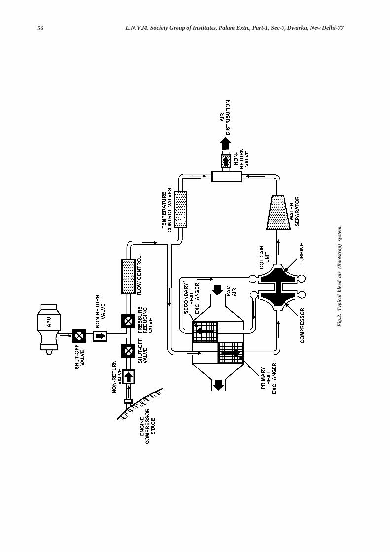
56 L.N.V.M. Society Group of Institutes, Palam Extn., Part-1, Sec-7, Dwarka, New Delhi-77
Fig
.2.
Typ
ical
ble
ed a
ir (
Boo
tstr
ap)
syst
em.
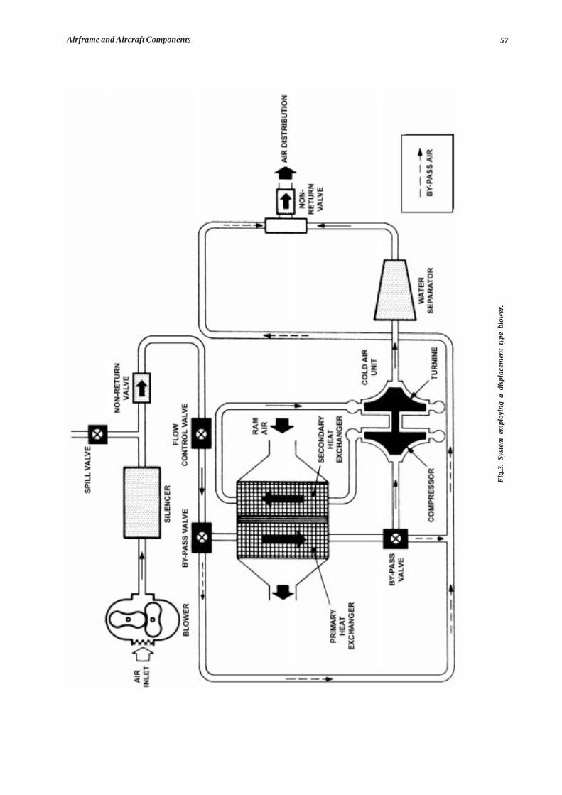
57Airframe and Aircraft Components
Fig
.3.
Sys
tem
em
ploy
ing
a di
spla
cem
ent
type
blo
wer
.
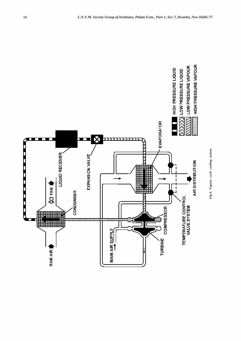
58 L.N.V.M. Society Group of Institutes, Palam Extn., Part-1, Sec-7, Dwarka, New Delhi-77
Fig
.4.
Vap
our
cycl
e co
olin
g sy
stem
.
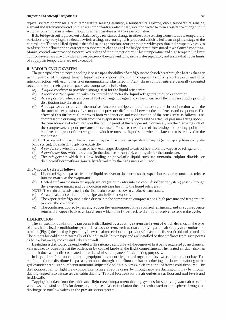
59Airframe and Aircraft Components
typical system comprises a duct temperature sensing element, a temperature selector, cabin temperature sensingelement and automatic control unit. These components are electrically interconnected to form a resistance bridge circuitwhich is only in balance when the cabin air temperature is at the selected valve.
If the bridge circuit is placed out of balance by a resistance change in either of the sensing elements due to temperaturevariation, or by varying the selector switch setting, an error signal is produced which is fed to an amplifier stage of thecontrol unit. The amplified signal is then fed to the appropriate actuator motors which position their respective valvesto adjust the air flows and so correct the temperature change until the bridge circuit is restored to a balanced condition.Manual controls are provided to permit overriding of the automatic circuit, low temperature and high temperature limitcontrol devices are also provided and respectively they prevent icing in the water separator, and ensure that upper limitsof supply air temperature are not exceeded.
II VAPOUR CYCLE SYSTEMThe principal of vapour cycle cooling is based upon the ability of a refrigerant to absorb heat through a heat exchanger
in the process of changing from a liquid into a vapour. The major components of a typical system and theirinterconnection with each other is diagrammatically illustrated in Fig.4, these components are generally mountedtogether to form a refrigeration pack, and comprise the following:
(a) A liquid receiver: to provide a storage area for the liquid refrigerant.(b) A thermostatic expansion valve: to control and meter the liquid refrigerant into the evaporator.(c) An evaporator: which is a form of heat exchanger designed to extract heat from the main air supply prior to
distribution into the aircraft.(d) A compressor: to provide the motive force for refrigerant re-circulation, and in conjunction with the
thermostatic expansion valve, maintain a pressure differential between the condenser and evaporator. Theeffect of this differential improves both vaporisation and condensation of the refrigerant as follows. Thecompressor in drawing vapour from the evaporator assembly, decrease the effective pressure acting upon it,the consequence of which reduces the boiling point of the refrigerant. Conversely, on the discharge side ofthe compressor, vapour pressure is increased. This has the effect of increasing the boiling point andcondensation point of the refrigerant, which returns to a liquid state when the latent heat is removed in thecondenser.
NOTE: The coupled turbine of the compressor may be driven by an independent air supply (e.g. a tapping from a wing de-icing system), the main air supply, or electrically(e) A condenser: which is a form of heat exchanger designed to extract heat from the vaporised refrigerant.(f) A condenser fan: which provides (in the absence of ram air), cooling air for the condenser.(g) The refrigerant: which is a low boiling point volatile liquid such as; ammonia, sulphur dioxide, or
dichlorodifluoromethane generally referred to by the trade name of ‘Freon’.
The Vapour Cycle is as follows(a) Liquid refrigerant passes from the liquid receiver to the thermostatic expansion valve for controlled release
into the matrix of the evaporator.(b) Heated air from the main air supply system (prior to entry into the cabin distribution system) passes through
the evaporator matrix and by induction releases heat into the liquid refrigerant.NOTE: The main air supply entering the distribution system is now at a reduced temperature.(c) As a consequence, the liquid refrigerant boils to a vapour.(d) The vaporised refrigerant is then drawn into the compressor, compressed to a high pressure and temperature
to enter the condenser.(e) The condenser; cooled by ram air, reduces the temperature of the vaporised refrigerant, and as a consequence
returns the vapour back to a liquid form which then flows back to the liquid receiver to repeat the cycle.
DISTRIBUTIONThe air used for conditioning purposes is distributed by a ducting system the layout of which depends on the type
of aircraft and its air conditioning system. In a basic system, such as that employing a ram air supply and combustionheating (Fig.1) the ducting is generally in two distinct sections and provides for separate flows of cold and heated air.The outlets for cold air are normally of the adjustable louvre type and are installed so that air flows from such pointsas below hat racks, cockpit and cabin sidewalls.
Heated air is distributed through outlet grilles situated at floor level, the degree of heat being regulated by mechanicalvalves directly controlled at the outlets, or by control knobs in the flight compartment. The heated air duct also hasa branch duct which directs heated air to the wind shield panels for demisting purposes.
In larger aircraft the air conditioning equipment is normally grouped together in its own compartment or bay. Theconditioned air is distributed to passenger cabins through underfloor and hat rack ducting, the latter containing outletgrilles and the requisite number of individual adjustable cold air louvres which are supplied from a cold air source. Thedistribution of air to flight crew compartments may, in some cases, be through separate ducting or it may be throughducting tapped into the passenger cabin ducting. Typical locations for the air outlets are at floor and roof levels andin sidewalls.
Tapping are taken form the cabin and flight crew compartment ducting systems for supplying warm air to cabinwindows and wind shields for demisting purposes. After circulation the air is exhausted to atmosphere through thedischarge or outflow valves in the pressurisation system.
60 L.N.V.M. Society Group of Institutes, Palam Extn., Part-1, Sec-7, Dwarka, New Delhi-77
MATERIALSMaterials used in the manufacture of typical ducting systems are light alloy, plastic, fibre glass reinforced plastic
and stainless steel, the latter being normally used for the hot air sections of engine bleed air supply systems. Thereare various methods of joining the duct sections together and to components. In those most commonly used the jointsare made by flanges and ring clamps of V-section, by rubber sleeves fitted over the ends of duct sections and securedeither by adjustable clamps or by a rubber adhesive, and by bolted flanges.
Fibreglass, formed into blanket sections by a covering of synthetic material e.g. nylon, is used for lagging of ductsections. To permit longitudinal movement of ducting as it expands and contracts, expansion bellows, sliding clampsand gimbal mountings are provided in some the larger aircraft systems.
HUMIDITY CONTROLIn some aircraft operating for long periods at high altitudes, it is necessary to increase the moisture content of the
air used for conditioning and pressurising the cabin in order to overcome physical discomfort arising from low relativehumidity. Various humidity control methods may be adopted but a typical system consists of humidifier unit suppliedwith water (from and individual at tank or galley water system) and also with air under pressure. The water and airsupplies; which are controlled by electromagnetic valves, pass through a jet nozzle system within the humidifier in sucha manner that the water is atomises and enters the distribution ducting in the form of a fine spray.
At the other extreme, operation of aircraft at low altitude and on the ground in regions of high relative humidity,necessitates a reduction of the moisture content of the air supply. In addition to the passenger comfort aspect, it isnecessary to decrease the humidity in order to reduce condensation and its effect.
GROUND AIR CONDITIONINGIn some aircraft provision is made for the conditioning of cabin air while an aircraft is on the ground. The methods
adopted depend on the type of aircraft and the associated air conditioning system.In aircraft employing combustion heating systems, cabin heating is normally obtained by switching on the heater
and a ventilating fan located in the main air supply ducting. On the ground, limited cooling of the cabin air can be obtainedby switching on the ventilating fan.
For heating the cabin air in aircraft equipped with an engine exhaust heating system it is necessary for the enginesto be running, and for the mechanical air flow control valves to be appropriately adjusted to provide the desiredconditions.
Aircraft using more complex methods of air conditioning are often provided, with special external connection towhich ground service equipment can be coupled. These units supply either preconditioned air into the main cabin airdistribution system or pressurised air into the air conditioning packs. In some cases ground service equipment maybe used when carrying out ground test procedures.
In addition to the ground connections, some aircraft are equipped with an auxiliary power unit for use in the absenceof ground conditioning units. Electrically operated blowers may also be fitted for use either as simple cool air ventilators,or in conjunction with a ‘bootstrap’ air conditioning system, to provide a flow of cooling air to the heat exchangers.
INSTALLATIONThe information given in the following paragraphs is of a general nature, and is intended as a guide to the procedures
associated with the installation of the principal component of air conditioning systems. Full details are contained inthe Maintenance Manuals for specific aircraft types and reference must therefore always be made to these documents.
Compressors and blowersBefore installation a check should be made to ensure that units are free from damage and that ducts air inlets and
outlets, and mating surfaces are free from oil, dust and other foreign matter. Rotors should also be checked for freedomof rotation observing any special precautions and procedures specified for the appropriate types of unit.
Pipes, metering units and filter of bearing lubricating oil systems should also be inspected for cleanliness and signsof cracks or other damage. Priming of the lubricating oil system should be carried out as specified in the Componentand Aircraft Maintenance Manuals.
Units must be adequately supported during installation to ensure that their weight is not allowed to bear on partsof the main drive; for example, a quill shaft which drives a displacement blower. In some aircraft employing compressorsa special hoist is provided for installation and removal of units and this should be used in the prescribed manner.
After a compressor or blower has been lowered on to the engine or gearbox mounting pad, its securing nuts or bolts,as appropriate, should be torque-tightened to the values specified in the Aircraft Maintenance Manual. In somecompressors installations the units must be secured by bolting them to the casing of their respective engines via linkassemblies.
Inlet and outlet duct attachment flanges should be clean and free from damage. In displacement blower systems,manifold normally provide for the attachment of duct sections to the blower casing. The bolts securing each manifoldto the blower. are, in some cases of different lengths. This must be re-fitted in their correct position before tighteningto avoid distortion of the inner face of the blower casing. New sealing rings should be fitted between duct section andcorresponding attachment points on compressors and blowers, and sections should fit squarely and not be subjectedto undue strain or load.
Combustion heatersBefore installation, combustion heaters should be inspected, and when necessary, pressure tested in the manner
61Airframe and Aircraft Components
prescribed in the Aircraft Maintenance Manual to ensure that no fuel or combustion products leak into the cabin airsupply.
Heaters should be installed in the manner specified in the Aircraft Maintenance Manual concerned taking care thatair and fuel leakages do not occur at duct joins or connections. There should be no connection between the combustionair and cabin air supplies and no leakage of air or exhaust gas into the aircraft.
Equipment associated with the heating system such as flow valves, air regulators, thermostatic devices and ductsshould be correctly interconnected, and mechanical movements, flows and temperature settings checked and adjusted.
After the installation of a heater the system should be ground tested in the manner specified in the relevant AircraftMaintenance Manual.
Engine exhaust heatersWhen installing heater muffs around piston engine exhaust systems it must be ensured that they are in such isolation
that exhaust gases cannot enter the muff and subsequently be discharged into the heating and ventilating system.Cooling air intakes and hot air ducting should be installed so that no obstruction or leakage of the air supply can occur.All joins should be correctly aligned and clamps securely fixed.
Heat exchangersBefore installation, heat exchangers should be inspected to ensure that no foreign matter has entered the various
connection, that there are no evident cracks or other damage and that ram air passages are free from obstruction.Heat exchangers are heavy units and they must therefore be adequately supported during installations to prevent
them fouling ducting, other system components and parts of the aircraft structure.The fore-and-aft and transverse clearances for mounting flanges and bolts should be checked to ensure that they
are within the limits specified in the relevant Maintenance Manuals. Mounting bolts should be tightened to theappropriate torque values.
New seals and O-rings should be fitted to the joints between system ducts, cooling air inlet and outlet flanges, andcharge-air connections. Nuts, bolts and clamps should not be over tightened as connections flanges may distort andcause damage to adjacent brazed joints. After installation the joints should be leak tested in accordance with theprocedure laid down in the relevant Aircraft Maintenance Manual.
If disturbed during installation of a heat exchanger, cooling air shutters of flaps should be tested and adjusted asnecessary. Moveable parts should operate freely, and the limits switches of electrical actuators should isolate the powersupply when the shutter or flap has moved through its full travel.
Cold air unitsWhen installing cold air units care is necessary to exclude dirt and oil from the air ducts and casings. Dirt and other
foreign matter may damage the rotating parts and oil may introduce unpleasant or flammable vapours into the cabinair supply. Duct attachment flanges, unit mounting flanges, and casings, should be examined for signs of burns, cracks,distortion or other damage.
Units with integral wet sump lubrication should be primed with oil to be approved specification to ensure that allbearings surfaces have been lubricated. Reference should be made to the Maintenance Manuals of relevant units fordetails of the lubricants required. The unit should be supported on a bench in the normal operating attitude while thequantity of oil specified for the unit is poured in. To ensure that oil is distributed to the bearings, the rotating assemblyof the unit should be spun over by hand at the same time checking that the rotation is free and without noise or vibration.The unit should then be drained and installed in the aircraft and after securing it to its appropriate mounting, refilledwith oil to the level marked on the sump dipstick.
NOTE: In some cold air units, air bearings are used to support the main rotating assembly, which do not allow free rotationfrom the idle state.The lubricants recommended for Cold Air Units are various and possibly incompatible with each other. Therefore,
when priming or servicing these units, care should be taken to ensure that the oil is of the correct type and specificationand the containers used are clean and free from contamination of any kind.
New seals should be fitted between the air distribution ducts and attachment flanges on the cold air unit, and whensecuring the ducts it should be ensured that they fit squarely and are not subjected to undue strain or load. Leak checkson units should be carried out during functional testing of the air conditioning system.
Refrigeration systemsThe individual components of a refrigeration system can usually be removed and installed separately. However the
Maintenance Manuals appropriate to the system and aircraft should always be referred to before attempting such work.Some of the general precautions applicable to closed Cycle System are as follows:
(a) Gloves and goggles should be worn when handling liquid refrigerants which can be harmful to the skin andeyes.
(b) Before filling a newly installed system, or refilling a system which has been partly disconnected, all air shouldbe evaluated in the manner prescribed in the relevant Maintenance Manual.
(c) While Refilling is in progress, care should be taken to ensure that refrigerant used is of the specified type, andquantity, and that all precautions recommended by the manufacturer are observed.
Temperature control system componentsThe temperature control of complex air conditioning system is usually accomplished either electrically or electronically.
62 L.N.V.M. Society Group of Institutes, Palam Extn., Part-1, Sec-7, Dwarka, New Delhi-77
Consequently the following precautions are normally adopted when installing such equipment are applicable.As temperature-sensing elements are positioned, so that it will be directly affected by the changes in duct and cabin
air temperatures. Care should be taken that element sensing cabin air temperature are not shielded by loose upholstery,and are protected, if paint spraying or similar operations are performed in their vicinity.
The damping effect of shock absorbers and anti-vibration mountings which may provide support for electronicamplifiers and similar sensitive equipment, should be checked by hand after installation.
Cables interconnecting components must be of the rating specified by the manufacturer and all connection mustbe clean and secured properly.
When installing control units, care should be taken that such controls are preset potentiometers and fine adjustmentresistors are not disturbed.
On completion of the installation of a component, sensitivity tests and final balance adjustments should be carriedout in accordance with the procedure laid down for the specific aircraft system. Tests of the overall controlling functionshould be made by selecting various temperature settings and noting that the actuators controlling such componentsas heat exchanger cooling air flaps, bypass valves, etc., move in the appropriate directions.
ValvesMechanically and electrically operated valves are employed in the various types of heating, ventilating and air
conditioning systems and therefore Maintenance Manuals should always be referred to for the appropriate installationprocedures. The details given in the following paragraph are of a general nature.
All valves should be inspected before installation for cleanliness, signs of damage and freedom of movement.Functional checks should be made on electrically-operated valves, e.g. spill valves bypass valves and choke valvesto ensure that limit switches are correctly adjusted at the extremes of valve travel.
Valves are often marked with arrows to indicate the direction of flow and particular care is necessary to ensure thatthe valve is installed in correct relation to flow.
The attachment of valves to their respective mountings and duct section must be secure and torque loadings strictlyobserved.
Electrical connections to actuators and to position indicators where fitted, should be checked against the relevantwiring diagrams and plugs, sockets and terminal screws checked for security.
On completion of the installation of a valve, an in-situ functional test should be carried out in accordance with theprocedure specified in the relevant Component and Aircraft Maintenance Manual.
Distribution systemsThe methods of installing ducting and other components of distribution systems depend on the type of air
conditioning system and reference must, therefore, always be made to the relevant Aircraft Maintenance Manual andthe procedures specified carried out.
The following summary serves a guide to some important aspects common to installation procedures:(a) Ducting should be inspected externally and internally for cleanliness, signs of damage and security of end
fittings.(b) Lagging, where fitted, should be inspected to ensure freedom from tears, damage and evidence of deterioration.(c) When fitting ring clamps, the sealing rings must be correctly positioned between duct and fittings squarely
before the clamps are tightened.(d) Ring clamps should be torque-tightened to the loads specified, the loadings should be rechecked after the
engine run following installation.(e) Ducts made from fibreglass, plastic and reinforced plastic should not be subjected to any weight or load during
installation, and the straps or clamps attaching the ducts to support brackets should not be over tightened.(f) After replacement of a duct, the disturbed joints should be checked for leakage.(g) Where specified, ducts must carry identification labels.(h) When assembled, on ducts rubber sleeves should be in a free condition, i.e. they should not be twisted, stepped
or collapsed.(i) Bedding tape or metal clips must be fitted between rubber sleeves and adjustable clamps to prevent damage
to the sleeves when tightening the clamps. Expansion bellows, sliding clamps or gimbal mountings whereinstalled, should be checked for full and free movement.
(j) Electrical bonding leads must be properly secured.
MAINTENANCEThe information given in the following paragraphs on maintenance periodic inspection and testing, is of a general
nature and should be read in conjunction with the Maintenance Manuals and Schedules for the components and aircraftconcerned.
Compressors and blowersUnits should be inspected for damage and for security of mountings attachment to engine drives and accessory
gearboxes, and also duct attachments.Oil transfer pipes should be examined for security of attachment, signs of chafing and other damage, and for leaks.
At the periods specified in the Maintenance Manual oil filters should be removed for examination and cleaning orrenewed as appropriate. If it is suspected that dirt is present in the lubrication system, all pipes and oil passages shouldbe cleaned in the manner prescribed in the Maintenance Manual for the relevant unit. In units having an internal
63Airframe and Aircraft Components
lubricating system, the oil level in the sump should be checked and replenished as necessary taking care that theequipment for dispensing the oil is scrupulously clean.
Where magnetic chip detectors are fitted to the lubrication system they should be removed and inspected for metalparticles. If no particles are found, the chip detector, together with a new sealing ring, should be refitted and wire locked.If metal particles are present the unit should be replaced with a serviceable item.
NOTE: When refitting bayonet type chip detectors extreme care should be taken to ensure positive engagement.
Combustion heatersHeaters should be examined for security of attachment and signs of malfunctioning, the fuel system should be
carefully checked for signs of leakage and drain pipes should be checked, ensure freedom from obstruction. At thespecified inspection periods igniter plugs should be cleaned, and heaters should be subjected to pressure test inaccordance with the procedure laid down by the manufacturer.
Electrical wiring and associated components should be checked for security of attachment, loose connections,chafing of insulation etc. The sheath of the igniter plug cable should be examined for any possible indications of arcing,which would be evidenced by burning or discoloration of the sheath.
Filters, air and fuel regulating devices, safety devices (e.g. overheat switches, fuel cutoff valves, etc.), and all controlsshould be inspected, adjusted and tested as required by the approved Maintenance Schedule.
System operation should be checked in accordance with the procedure laid down in the relevant AircraftMaintenance Manual.
NOTE: In order to reduce the risk of the cabin air supply becoming contaminated by high concentrations of carbon monoxidefrom the exhaust system, it is imperative that the procedures for inspection, servicing and overhaul of combustion heaters andtheir associated exhaust systems are maintained to a high level.
Engine exhaust heatingCareful examination of heater muffs is necessary to ensure that no leakage of exhaust gases into the air delivered
to the cabin can occur. Unless damage can be rectified within the scope of an approved repair scheme, exhaust pipesor muffs which show signs of cracking, corrosion or excessive high temperature scaling should be renewed. All muffsshould be pressure-tested when specified in the Maintenance Schedule.
Hot and cold air ducts associated with the heating system should be free from obstruction and all controllableshutters, valves etc., should be checked for correct functioning. The operation of the complete system should bechecked during engine running.
Heat exchangersHeat exchangers should be inspected for security of attachment to the aircraft structure, security of air duct
connection and freedom from damage.The external surfaces of a heat exchanger matrix must be clean and the cooling air passages free from obstruction.
If dirt or other forms of contamination are found the surface and air passages should be cleaned by means of a cleandry air blast.
If a matrix has not been satisfactorily cleaned due to the contamination being excessive or hardened on to thesurfaces, or if internal contamination or leakage from the charge air passages is suspected, the heat exchanger shouldbe removed for cleaning and repair and replaced by a serviceable unit.
Cooling air shutters or flaps, linkages and actuators should be examined for freedom of movement and should belubricated when necessary. Linkages and hinges an shutters or flaps should be checked for excessive play and lostmotion.
During functional testing of a complete air conditioning system, a check should be made at all joints for air leakage.
Cold air unitsCold air units should be inspected for security of mountings and external locking devices, cleanliness, freedom from
damage, oil leaks, and leakage of air from duct connections. In some units a magnetic chip detector is fitted to the oilsump drain plug; this should be removed and inspected for metal particles. If particles are present, the cold air unit shouldbe replaced by a serviceable. If no particles are present, the chip detector refitted together with new sealing ring andwire-locked.
The oil level must be checked and replenished if necessary taking care that the oil is to the specification approvedfor the unit, that the equipment for dispensing the oil is scrupulously clean, and that the system is not overfilled.
Refrigeration systemsRefrigeration packs and associated components should be checked for security of mountings, security of pipe line
connections between components and level of refrigerant. If the level is low the system should be checked for leaksand, after rectification, recharged with the refrigerant specified for the system taking care that all precautions areobserved.
Temperature and control systemAll components should be inspected for security of mounting and electrical connection , signs of damage,
deterioration of electrical cables etc.The operation of individual components should be checked during specified ground tests to ensure that they
respond correctly whenever different heating and cooling and conditions are selected, and also that, in combination,
64 L.N.V.M. Society Group of Institutes, Palam Extn., Part-1, Sec-7, Dwarka, New Delhi-77
they maintain cabin temperature conditions within a comfortable range. It should be borne in mind that, apart fromconsideration control of comfort, cabin temperature control limits the misting and icing of windscreens and windowsand therefore affects the safe operation of aircraft. The operation of components, systems and circuits, designedspecifically for emergency operating conditions, must also be checked during ground test procedures.
The test procedures vary and the extent to which a system can be tested may be limited, particularly in relation toram air methods of cooling. On the other hand, full-range temperature control of a system in some aircraft may be checkedon the ground. Reference must therefore always be made to the relevant Aircraft Maintenance Manual and MaintenanceSchedule for the procedure to be adopted and precautions to be observed.
ValvesThe maintenance of valves associated with air temperature control is usually confined to; inspection for cleanliness,
security of mounting ducting attachments and, where applicable, security of electrical connections, functioning testsand light lubrication specified by the manufacturer of the component.
Sliding or rotating parts of valve assemblies should be free from scores, damage or excess static friction. The maximumeffort required to move a valve should be checked when necessary and should not exceed the figure recommended bythe manufacturer. However some electric-mechanically operated valves are not designed to operate without theapplication of an electrical supply. Therefore reference should be made to the specific Maintenance Manual for testinstruction, before manual operation.
Lubricants should be of the type specified for the component and should be applied sparing taking care to preventoil entering air supply ducts.
Valve seats and valves faces should be kept free of dust or traces of lubricant.Checks on the operation of valves should normally be carried out during ground testing of temperature control
systems since their functions are integrated.
Distribution systemsAll ducting and associated air distribution components should be inspected for security and general condition,
particular attention being given to joints between duct section and components.Lagging should always be properly secured and free from oil hydraulic fluids etc. It should be remembered that duct
sections in some parts of a system often become heated to a degree sufficient to make oil-soaked lagging flammable.When specified, ducts should be proof-tested at the pressure recommended by the manufacturer. Pressure tests
are however, more often made with the object of detecting leaks, in which case the test pressure is not critical providedit does not exceed a value which might damage the duct.
It is usually more convenient to test a complete distribution system by dividing it into section and applying arecommended pressure separately and in sequence. The sections should be selected so that all critical joints aresubjected to the test pressure; advantage being taken of shut-off valves, non-return valves, etc., where these provideconvenient boundaries between sections.
Leaks can be detected by ear although these are sometimes revealed by discoloration and holes blown in the lagging.If there is difficulty in locating leaks, the soap and water method can be used.
NOTE: Because of the high operating temperatures and pressures involved, it is recommended that care should be taken whencarrying out a physical check for air leaks.
� � �
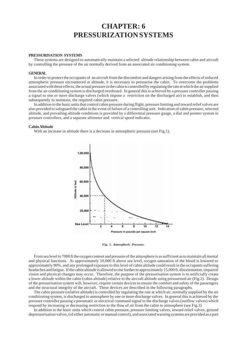
65Airframe and Aircraft Components
CHAPTER: 6PRESSURIZATION SYSTEMS
PRESSURISATION SYSTEMSThese systems are designed to automatically maintain a selected altitude relationship between cabin and aircraft
by controlling the pressure of the air normally derived from an associated air conditioning system.
GENERALIn order to protect the occupants of an aircraft from the discomfort and dangers arising from the effects of reduced
atmospheric pressure encountered at altitude, it is necessary to pressurise the cabin. To overcome the problemsassociated with these effects, the actual pressure in the cabin is controlled by regulating the rate at which the air suppliedfrom the air conditioning system is discharged overboard. In general this is achieved by a pressure controller passinga signal to one or more discharge valves (which impose a restriction on the discharged air) to establish, and thensubsequently to maintain, the required cabin pressure.
In addition to the basic units that control cabin pressure during flight, pressure limiting and inward relief valves arealso provided to safeguard the cabin in the event of failure of a controlling unit. Indication of cabin pressure, selectedaltitude, and prevailing altitude conditions is provided by a differential pressure gauge, a dial and pointer system inpressure controllers, and a separate altimeter and vertical speed indicator.
Cabin AltitudeWith an increase in altitude there is a decrease in atmospheric pressure (see Fig.1).
Fig. 1. Atmospheric Pressure.
From sea level to 7000 ft the oxygen content and pressure of the atmosphere is so sufficient as to maintain all mentaland physical functions. At approximately 10,000 ft above sea level, oxygen saturation of the blood is lowered toapproximately 90%, and any prolonged exposure to this level of cabin altitude could result in the occupants sufferingheadaches and fatigue. If the cabin altitude is allowed to rise further to approximately 15,000 ft, disorientation, impairedvision and physical changes may occur. Therefore, the purpose of the pressurisation system is to artificially createa lower altitude within the cabin (cabin altitude) relative to the aircraft altitude using pressurised air (Fig.2). Designof the pressurisation system will, however, require certain devices to ensure the comfort and safety of the passengersand the structural integrity of the aircraft. These devices are described in the following paragraphs.
The cabin pressure (relative altitude) is controlled by regulating the rate at which air, normally supplied by the airconditioning system, is discharged to atmosphere by one or more discharge valves. In general this is achieved by thepressure controller passing a pneumatic or electrical command signal to the discharge valves (outflow valves) whichrespond by increasing or decreasing restriction to the flow of air from the cabin to atmosphere (see Fig.3)
In addition to the basic units which control cabin pressure, pressure limiting valves, inward relief valves, grounddepressurisation valves, (of either automatic or manual control), and associated warning systems are provided as a part
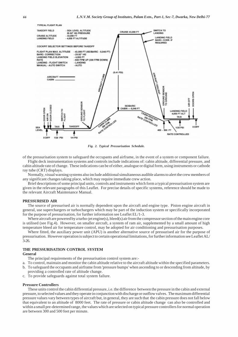
66 L.N.V.M. Society Group of Institutes, Palam Extn., Part-1, Sec-7, Dwarka, New Delhi-77
of the pressurisation system to safeguard the occupants and airframe, in the event of a system or component failure.Flight deck instrumentation systems and controls include indications of: cabin altitude, differential pressure, and
cabin altitude rate of change. These indications can be of either, analogue or digital form, using instruments or cathoderay tube (CRT) displays.
Normally, visual warning systems also include additional simultaneous audible alarms to alert the crew members ofany significant changes taking place, which may require immediate crew action.
Brief descriptions of some principal units, controls and instruments which form a typical pressurisation system aregiven in the relevant paragraphs of this Leaflet. For precise details of specific systems, reference should be made tothe relevant Aircraft Maintenance Manual.
PRESSURISED AIRThe source of pressurised air is normally dependent upon the aircraft and engine type. Piston engine aircraft in
general, use superchargers or turbochargers which may be part of the induction system or specifically incorporatedfor the purpose of pressurisation, for further information see Leaflet EL/1-3.
Where aircraft are powered by a turbo-jet engine(s), bleed(s) air from the compressor section of the main engine coreis utilised (see Fig.4). However, on smaller aircraft, a system of ram air, supplemented by a small amount of hightemperature bleed air for temperature control, may be adopted for air conditioning and pressurisation purposes.
Where fitted, the auxiliary power unit (APU) is another alternative source of pressurised air for the purpose ofpressurisation. However operation is subject to certain operational limitations, for further information see Leaflet AL/3-26.
THE PRESSURISATION CONTROL SYSTEMGeneral
The principal requirements of the pressurisation control system are:-a. To control, maintain and monitor the cabin altitude relative to the aircraft altitude within the specified parameters.b. To safeguard the occupants and airframe from 'pressure bumps' when ascending to or descending from altitude, by
providing a controlled rate of altitude change.c. To provide safeguards against total system failure.
Pressure ControllersThese units control the cabin differential pressure, i.e. the difference between the pressure in the cabin and external
pressure, to selected values and they operate in conjunction with discharge or outflow valves. The maximum differentialpressure values vary between types of aircraft but, in general, they are such that the cabin pressure does not fall belowthat equivalent to an altitude of 8000 feet. The rate of pressure or cabin altitude change can also be controlled andwithin a small pre-determined range, the values which are selected on typical pressure controllers for normal operationare between 300 and 500 feet per minute.
Fig. 2. Typical Pressurisation Schedule.
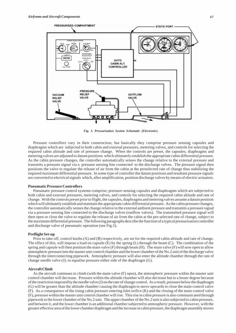
67Airframe and Aircraft Components
Pressure controllers vary in their construction, but basically they comprise pressure sensing capsules anddiaphragms which are subjected to both cabin and external pressures, metering valves, and controls for selecting therequired cabin altitude and rate of pressure change. When the controls are preset, the capsules, diaphragms andmetering valves are adjusted to datum positions which ultimately establish the appropriate cabin differential pressure.As the cabin pressure changes, the controller automatically senses the change relative to the external pressure andtransmits a pressure signal via a pressure sensing line connected to the discharge valves. The pressure signal thenpositions the valve to regulate the release of air from the cabin at the preselected rate of change thus stabilizing therequired maximum differential pressure. In some type of controller the datum positions and resultant pressure signalsare converted to electrical signals which, after amplification, position discharge valves by means of electric actuators.
Pneumatic Pressure ControllersPneumatic pressure control systems comprise; pressure-sensing capsules and diaphragms which are subjected to
both cabin and external pressures, metering valves, and controls for selecting the required cabin altitude and rate ofchange. With the controls preset prior to flight, the capsules, diaphragms and metering valves assume a datum positionwhich will ultimately establish and maintain the appropriate cabin differential pressure. As the cabin pressure changes,the controller automatically senses the change relative to the external ambient pressure and transmits a pressure signalvia a pressure sensing line connected to the discharge valves (outflow valves). The transmitted pressure signal willthen open or close the valve to regulate the release of air from the cabin at the pre-selected rate of change, subject tothe maximum differential pressure. The following paragraphs describe the function of a typical pressurisation controllerand discharge valve of pneumatic operation (see Fig.5).
Preflight Set-upPrior to take off, control knobs (A) and (B) respectively, are set for the required cabin altitude and rate of change.
The effect of this, will impose a load on capsule (E) by the spring (L) through the beam (C). The combination of thespring and capsule will then position the main valve (F) through beam (H). The main valve (F) will now open to allowatmospheric pressure into the master unit control chamber and the lower chamber of the No.2 unit of the discharge valvethrough the interconnecting pipework. Atmospheric pressure will also enter the altitude chamber through the rate ofchange needle valve (J), to equalise pressure either side of the diaphragm (G).
Aircraft ClimbAs the aircraft continues to climb (with the main valve (F) open), the atmospheric pressure within the master unit
control chamber will decrease. Pressure within the altitude chamber will also decrease but to a lesser degree becauseof the restriction imposed by the needle valve (J) on the rate of change control. As a result, pressure below the diaphragm(G) will be greater than the altitude chamber causing the diaphragm to move upwards to close the main control valve(F). As a consequence of the rising cabin pressure entering inlet orifice (K) and the closing of the main control valve(F), pressure within the master unit control chamber will rise. This rise in cabin pressure is also communicated throughpipework to the lower chamber of the No.2 unit. The upper chamber of the No.2 unit is also subjected to cabin pressure,and between it, and the lower chamber is an additional chamber subjected to atmospheric pressure. However, with thegreater effective area of the lower chamber diaphragm and the increase in cabin pressure, the diaphragm assembly moves
Fig. 3. Pressurisation System Schematic (Electronic).
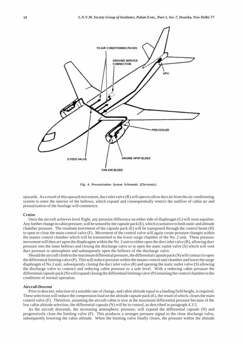
68 L.N.V.M. Society Group of Institutes, Palam Extn., Part-1, Sec-7, Dwarka, New Delhi-77
upwards. As a result of this upward movement, duct inlet valve (R) will open to allow duct air from the air conditioningsystem to enter the interior of the bellows, which expand and consequentially restrict the outflow of cabin air andpressurisation of the fuselage will commence.
CruiseOnce the aircraft achieves level flight, any pressure difference on either side of diaphragm (G) will soon equalise.
Any further change in cabin pressure, will be sensed by the capsule pack (E), which is sensitive to both static and altitudechamber pressure. The resultant movement of the capsule pack (E) will be transposed through the control beam (H)to open or close the main control valve (F). Movement of the control valve will again create pressure changes withinthe master control chamber which will be transmitted to the lower surge chamber of the No. 2 unit. These pressuremovement will then act upon the diaphragms within the No. 2 unit to either open the duct inlet valve (R), allowing ductpressure into the inner bellows and closing the discharge valve or to open the static outlet valve (S) which will ventduct pressure to atmosphere and subsequently open the bellows of the discharge valve.
Should the aircraft climb to the maximum differential pressure, the differential capsule pack (N) will contract to openthe differential limiting valve (P). This will reduce pressure within the master control unit chamber and lower the surgediaphragm of No.2 unit, subsequently closing the duct inlet valve (R) and opening the static outlet valve (S) allowingthe discharge valve to contract and reducing cabin pressure to a safe level. With a reducing cabin pressure thedifferential capsule pack (N) will expand closing the differential limiting valve (P) returning the control chamber to theconditions of normal operation.
Aircraft DescentPrior to descent, selection of a suitable rate of change, and cabin altitude equal to a landing field height, is required.
These selections will reduce the compression load on the altitude capsule pack (E), the result of which, closes the maincontrol valve (F). Therefore, assuming the aircraft cabin is now at the maximum differential pressure because of thelow cabin altitude selection, the differential capsule (N) will be in control, as described in paragraph 4.3.5.
As the aircraft descends, the increasing atmospheric pressure, will expand the differential capsule (N) andprogressively close the limiting valve (P). This produces a stronger pressure signal to the close discharge valve,subsequently lowering the cabin altitude. When the limiting valve finally closes, the pressure within the altitude
Fig. 4. Pressurisation System Schematic (Electronic).
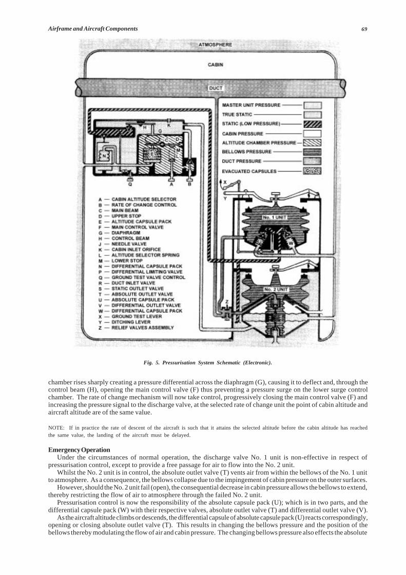
69Airframe and Aircraft Components
chamber rises sharply creating a pressure differential across the diaphragm (G), causing it to deflect and, through thecontrol beam (H), opening the main control valve (F) thus preventing a pressure surge on the lower surge controlchamber. The rate of change mechanism will now take control, progressively closing the main control valve (F) andincreasing the pressure signal to the discharge valve, at the selected rate of change unit the point of cabin altitude andaircraft altitude are of the same value.
NOTE: If in practice the rate of descent of the aircraft is such that it attains the selected altitude before the cabin altitude has reachedthe same value, the landing of the aircraft must be delayed.
Emergency OperationUnder the circumstances of normal operation, the discharge valve No. 1 unit is non-effective in respect of
pressurisation control, except to provide a free passage for air to flow into the No. 2 unit.Whilst the No. 2 unit is in control, the absolute outlet valve (T) vents air from within the bellows of the No. 1 unit
to atmosphere. As a consequence, the bellows collapse due to the impingement of cabin pressure on the outer surfaces.However, should the No. 2 unit fail (open), the consequential decrease in cabin pressure allows the bellows to extend,
thereby restricting the flow of air to atmosphere through the failed No. 2 unit.Pressurisation control is now the responsibility of the absolute capsule pack (U); which is in two parts, and the
differential capsule pack (W) with their respective valves, absolute outlet valve (T) and differential outlet valve (V).As the aircraft altitude climbs or descends, the differential capsule of absolute capsule pack (U) reacts correspondingly,
opening or closing absolute outlet valve (T). This results in changing the bellows pressure and the position of thebellows thereby modulating the flow of air and cabin pressure. The changing bellows pressure also effects the absolute
Fig. 5. Pressurisation System Schematic (Electronic).
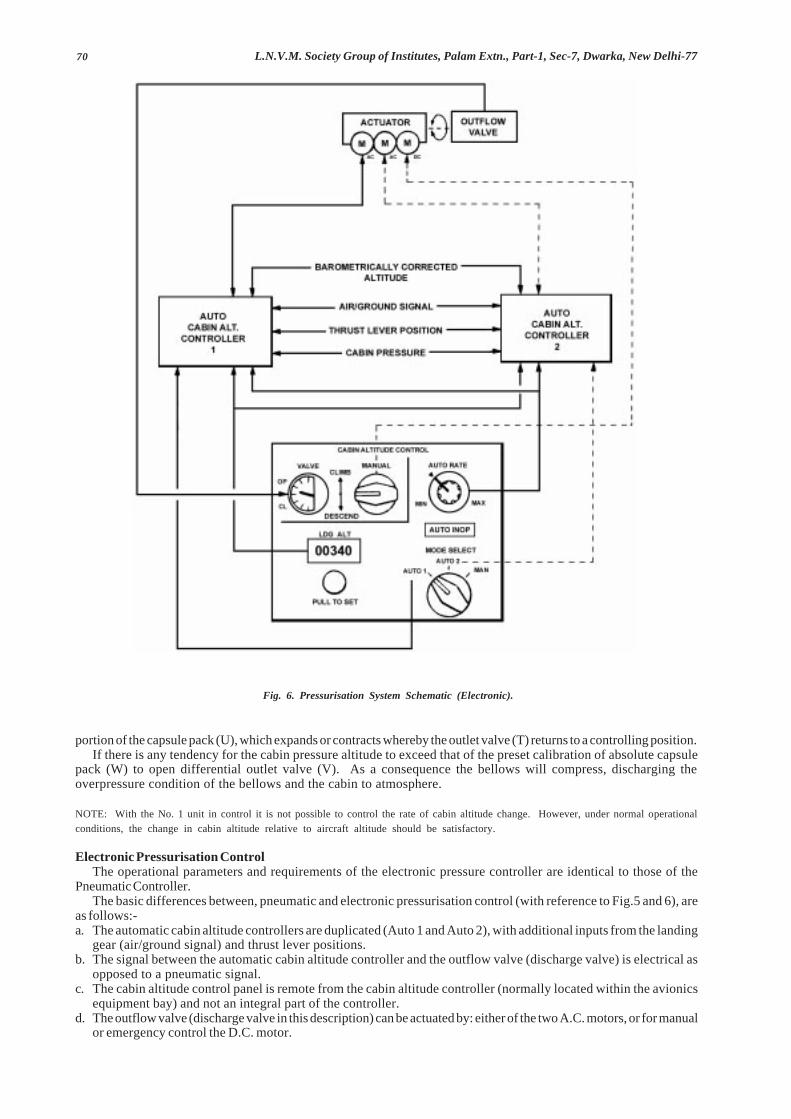
70 L.N.V.M. Society Group of Institutes, Palam Extn., Part-1, Sec-7, Dwarka, New Delhi-77
portion of the capsule pack (U), which expands or contracts whereby the outlet valve (T) returns to a controlling position.If there is any tendency for the cabin pressure altitude to exceed that of the preset calibration of absolute capsule
pack (W) to open differential outlet valve (V). As a consequence the bellows will compress, discharging theoverpressure condition of the bellows and the cabin to atmosphere.
NOTE: With the No. 1 unit in control it is not possible to control the rate of cabin altitude change. However, under normal operationalconditions, the change in cabin altitude relative to aircraft altitude should be satisfactory.
Electronic Pressurisation ControlThe operational parameters and requirements of the electronic pressure controller are identical to those of the
Pneumatic Controller.The basic differences between, pneumatic and electronic pressurisation control (with reference to Fig.5 and 6), are
as follows:-a. The automatic cabin altitude controllers are duplicated (Auto 1 and Auto 2), with additional inputs from the landing
gear (air/ground signal) and thrust lever positions.b. The signal between the automatic cabin altitude controller and the outflow valve (discharge valve) is electrical as
opposed to a pneumatic signal.c. The cabin altitude control panel is remote from the cabin altitude controller (normally located within the avionics
equipment bay) and not an integral part of the controller.d. The outflow valve (discharge valve in this description) can be actuated by: either of the two A.C. motors, or for manual
or emergency control the D.C. motor.
Fig. 6. Pressurisation System Schematic (Electronic).
71Airframe and Aircraft Components
The electronic pressurisation controller (the cabin altitude controller in Fig.6) is, in basic terms, a shaping andsumming network. With information derived from the air data computer, cabin altitude control and various systemswithin the aircraft, a reference signal is produced by the controller. This reference signal will then be compared by thecabin altitude controller, to the signal produced by the cabin altitude monitor. If a disagreement exists between the twosignals, a correcting error signal is produced, which when applied, modulates the outflow valve (s).
As a safeguard against the cabin altitude or rate of change exceeding defined limits within the pressurisationschedule, override circuits constantly monitor the performance of the system in control. If any deviation from theschedule exists, the override circuits will either: automatically transfer control to the standby system, (Auto 1 to Auto2) or de-activate the system completely with the appropriate flight deck indications and aural warnings. The followingparagraphs describe the operation of a typical electronic controller.
Preflight Set-upAutomatic electronically controlled cabin pressurisation systems in general terms require the following action prior
to take-off:-a. Provision of pressurised air from the air conditioning system.b. The setting of landing field height (QFE).c. Rate of cabin altitude change.
PrepressurisationWhere prepressurisation of the cabin prior to take-off is part of the pressurisation schedule, control inputs will be
required of the: landing gear (air/ground signal), engine oil pressure, forward throttle position, and the door warningsystem. The cabin pressure within this part of the schedule is normally only marginally above the ambient atmosphericpressure (i.e. a cabin altitude just below airfield altitude).
ClimbPrepressurisation ceases when the aircraft leaves the ground and the landing gear and oleo fully extends (air/ground
signal). The cabin altitude climb sequence of the pressurisation schedule will now commence with the cabin altituderate of change limited to approximately 500 ft per minute.
CruiseWith the aircraft maintaining a constant height, the cruise sequence of the pressurisation schedule will commence.
Simultaneously, the cabin altitude controller will, for the purpose of originating a datum point for a scheduled descent,and any correction of the cabin cruise altitude, compare the theoretical cabin altitude to that of the selected landingaltitude. Any variation to aircraft altitude, in climb, or descent of less than 500 ft, the corresponding cabin altitude willremain unchanged. If, however, the aircraft altitude climbs or descends by more than 500 ft, the cabin altitude controllerwill enter into an appropriate auto schedule subject to the various controlling parameters i.e. take-off height, landingfield height and selected auto rate of change.
DescentThe descent sequence of the pressurisation schedule is normally initiated by a descending aircraft altitude of
approximately 500 ft and subject to the following criteria:-a. The relative aircraft altitude.b. The auto rate selected.c. The landing field height (QFE).d. The maximum cabin to ambient differential pressure limit.
LandingFor those aircraft which are designed to land in a pressurised condition, the cabin altitude controller will normally
automatically lower the selected landing field by approximately 100 ft height. As a result the cabin will remain pressurisedmarginally above atmospheric pressure until touch down, where the landing gear air/ground signal takes precedencefor controlled depressurisation of the aircraft.
Emergency OperationProtection against system failure is provided for by duplication of the control system. In the event of a system or
power failure, control will be automatically transferred to the standby system which is electrically supplied from analternate source. If total system failure does occur, a reversion to manual control will be required.
OUTFLOW VALVES (DISCHARGE VALVES)
DISCHARGE VALVESThe primary function of discharge or outflow valves is to regulate the discharge of cabin air in response to the
pressure signals received from the controller. They also vary in design and construction but, in general, they are oftwo main types. In one type the valves are operated by diaphragms and in the other by electric actuators. The sizeand number of valves required for a particular type of aircraft is governed by the amount of air necessary for pressurizing,heating and cooling purposes. In some types of discharge valve, safety valves and inward relief valves are incorporated.
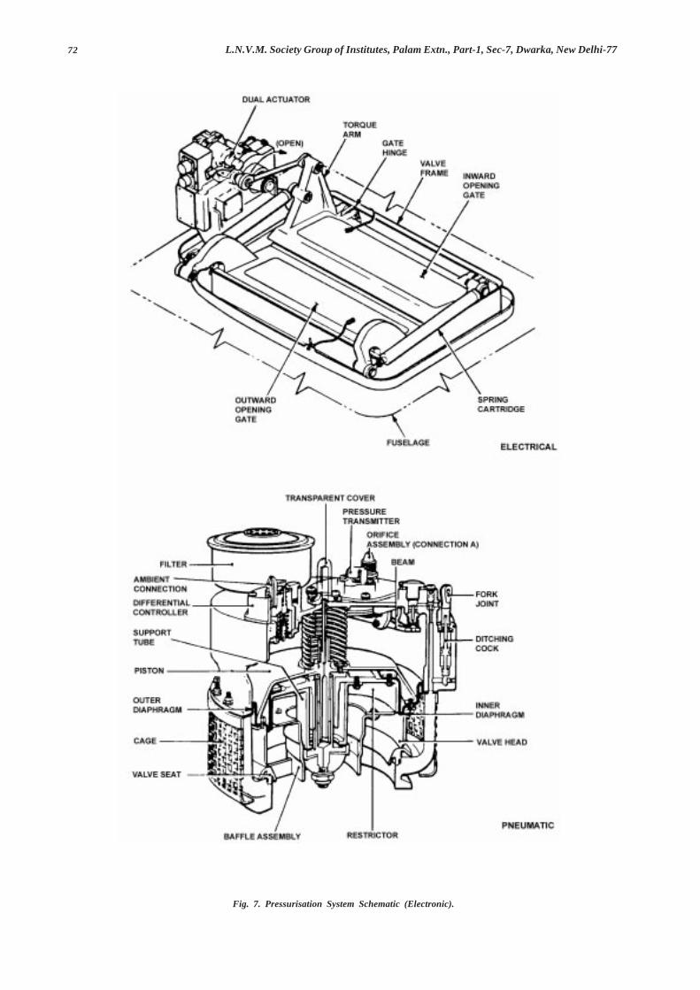
72 L.N.V.M. Society Group of Institutes, Palam Extn., Part-1, Sec-7, Dwarka, New Delhi-77
Fig. 7. Pressurisation System Schematic (Electronic).
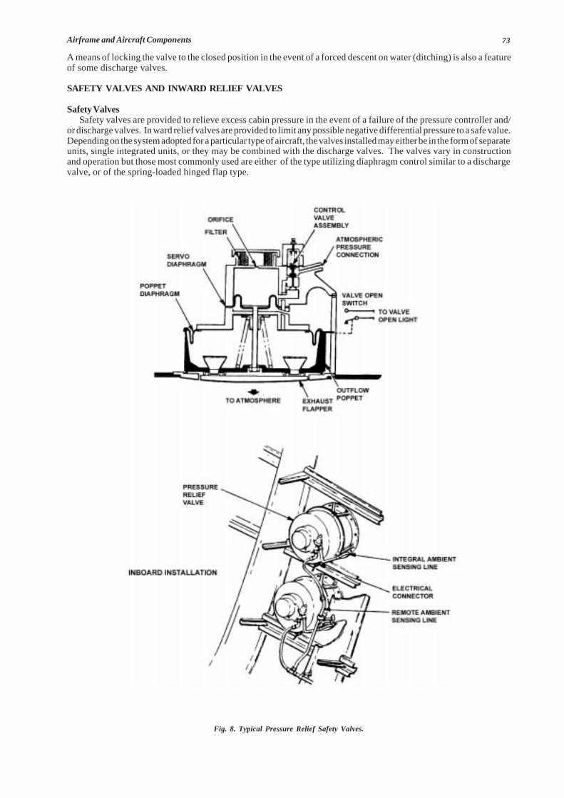
73Airframe and Aircraft Components
A means of locking the valve to the closed position in the event of a forced descent on water (ditching) is also a featureof some discharge valves.
SAFETY VALVES AND INWARD RELIEF VALVES
Safety ValvesSafety valves are provided to relieve excess cabin pressure in the event of a failure of the pressure controller and/
or discharge valves. In ward relief valves are provided to limit any possible negative differential pressure to a safe value.Depending on the system adopted for a particular type of aircraft, the valves installed may either be in the form of separateunits, single integrated units, or they may be combined with the discharge valves. The valves vary in constructionand operation but those most commonly used are either of the type utilizing diaphragm control similar to a dischargevalve, or of the spring-loaded hinged flap type.
Fig. 8. Typical Pressure Relief Safety Valves.
74 L.N.V.M. Society Group of Institutes, Palam Extn., Part-1, Sec-7, Dwarka, New Delhi-77
Inward Relief ValvesInward relief valves are provided to limit any possible negative differential pressure to a safe value. Depending on
the system adopted for the particular aircraft type, the valves installed may either be in the form of separate units, singleintegrated units, or combined with the discharge valves. The valves vary in construction and operation but those mostcommonly used are of the type utilising diaphragm control (similar to a discharge valve).
GROUND AUTOMATIC RELIEF VALVESThe ground automatic relief valve is a form of discharge valve used on some aircraft types which is additional to
those discharge valves which form part of the pressurisation system. The valve as its title implies, is effectual whilstthe aircraft is in a ground mode (i.e. ground/air signal) with the following primary functions:-a. To maintain a free flow of ventilating air within the aircraft when parked.b. To prevent cabin pressurisation and pressure surges whilst the aircraft is taxiing.c. To transmit ground/air signals derived from the landing gear and engine thrust levers, to the cabin altitude controller
for controlled prepressurisation and depressurisation of the cabin when respectively the aircraft is taking off orlanding.
INSTRUMENTS AND INDICATORSGeneral
The presentation of instrumentation forming part of the pressurisation control system, is largely dependent uponthe method of pressurisation control. Pneumatic pressure controllers; as described in paragraph 4.3, have the principalinstruments as an integral part of the control panel. Electronic pressure controllers; as described in paragraph 4.4, haveinstruments which are remote from the controller and generally form part of the cabin altitude control panel.
InstrumentsThe principal instruments in respect of pressurisation control are, Cabin altitude, Differential pressure, and Rate of
Change (vertical speed). These are generally positioned as described in paragraph 8.1, or as a cathode ray tube (CRT)generated display in either digital or analogue (dial and pointer) form in the main instrument panel. Instruments mayalso be provided to indicate the position of certain valves, e.g. discharge valves.
IndicatorsCrew compartment indications, are in general, presented in visual and audio form, i.e. warning light or CRT image
with an accompanying sound (bell, chime or horn etc). The factors which will activate those indications, in respect ofthe cabin altitude control are:-a. Excessive cabin altitude.b. Discharge valve failure or disagreement.c. Inward relief valve operation.d. An automatic system changeover.e. Excessive differential pressure.f. Positive pressure relief valve operation.
EMERGENCY CONTROLSIn addition to the normal devices which control pressure to the required values, provision is made for the normal
operating cabin pressure to be reduced rapidly in the event of, emergency landings, clearing the cabin of smoke or othercontaminations, and the rapid reduction of cabin pressure. In all such cases cabin pressure is reduced by the ‘dumping’of air. This may be achieved in a number of ways and the methods most commonly adopted include, separate manuallyoperated dump valves, manual override control of a discharge valve or a safety valve, and in some cases manual controlof a pressure controller.
FILTERS AND AIR DRIERSFilters are connected in the cabin air pressure sensing lines to the pressure controllers and discharge valves and
normally consist of a casing housing a replaceable filter cartridge and fitted with appropriate inlet and outletconnections. In some aircraft installations, air driers are provided to eliminate the possibility sensing lines to dischargevalves, safety valves and inward relief valves. Two types of driers are in common use; one utilizing the properties ofa silica gel drying agent, and the other consisting of a baffle box mounted on the inside of the fuselage skin and utilizingthe skin temperature to condense any water vapour present in the cabin air. The moisture deposited in the box eventuallydrains away through an outlet in the box and aircraft skin.
� � �
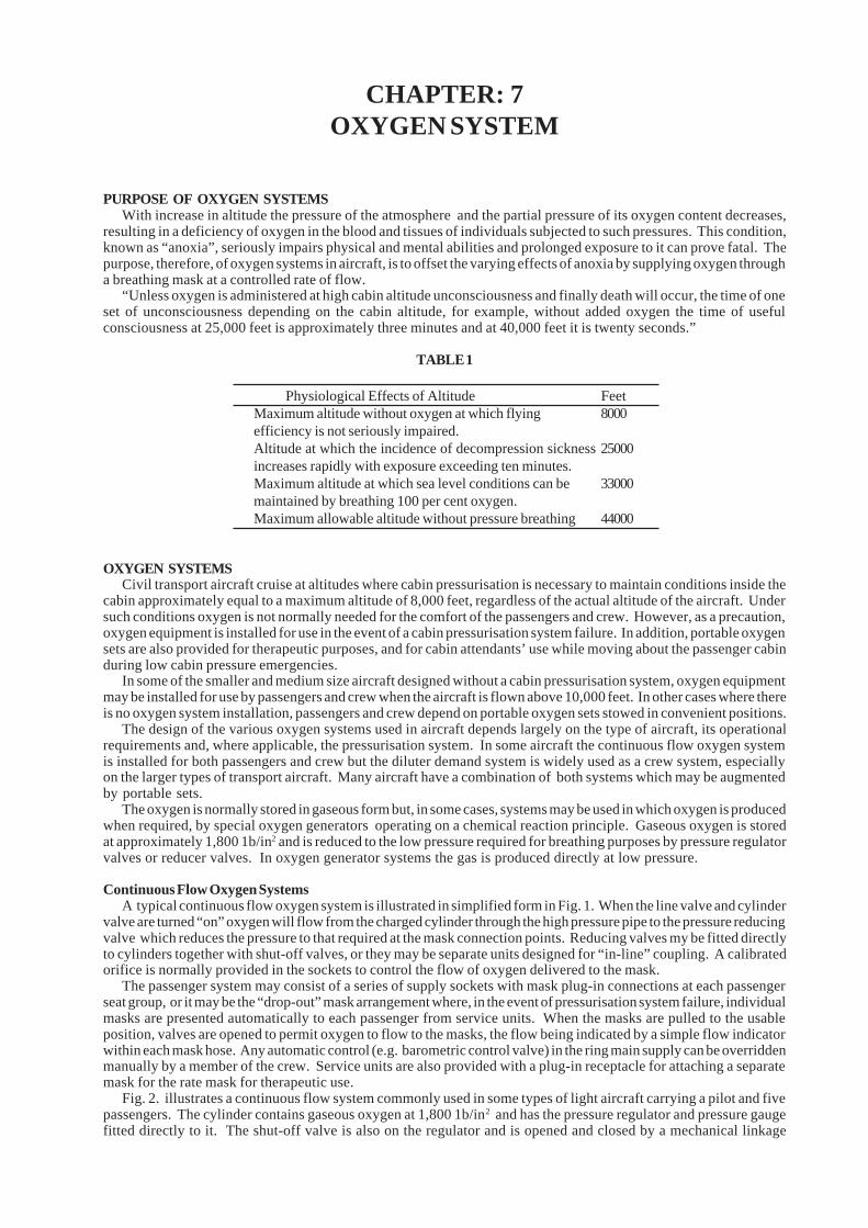
75Airframe and Aircraft Components
CHAPTER: 7OXYGEN SYSTEM
PURPOSE OF OXYGEN SYSTEMSWith increase in altitude the pressure of the atmosphere and the partial pressure of its oxygen content decreases,
resulting in a deficiency of oxygen in the blood and tissues of individuals subjected to such pressures. This condition,known as “anoxia”, seriously impairs physical and mental abilities and prolonged exposure to it can prove fatal. Thepurpose, therefore, of oxygen systems in aircraft, is to offset the varying effects of anoxia by supplying oxygen througha breathing mask at a controlled rate of flow.
“Unless oxygen is administered at high cabin altitude unconsciousness and finally death will occur, the time of oneset of unconsciousness depending on the cabin altitude, for example, without added oxygen the time of usefulconsciousness at 25,000 feet is approximately three minutes and at 40,000 feet it is twenty seconds.”
TABLE 1
OXYGEN SYSTEMSCivil transport aircraft cruise at altitudes where cabin pressurisation is necessary to maintain conditions inside the
cabin approximately equal to a maximum altitude of 8,000 feet, regardless of the actual altitude of the aircraft. Undersuch conditions oxygen is not normally needed for the comfort of the passengers and crew. However, as a precaution,oxygen equipment is installed for use in the event of a cabin pressurisation system failure. In addition, portable oxygensets are also provided for therapeutic purposes, and for cabin attendants’ use while moving about the passenger cabinduring low cabin pressure emergencies.
In some of the smaller and medium size aircraft designed without a cabin pressurisation system, oxygen equipmentmay be installed for use by passengers and crew when the aircraft is flown above 10,000 feet. In other cases where thereis no oxygen system installation, passengers and crew depend on portable oxygen sets stowed in convenient positions.
The design of the various oxygen systems used in aircraft depends largely on the type of aircraft, its operationalrequirements and, where applicable, the pressurisation system. In some aircraft the continuous flow oxygen systemis installed for both passengers and crew but the diluter demand system is widely used as a crew system, especiallyon the larger types of transport aircraft. Many aircraft have a combination of both systems which may be augmentedby portable sets.
The oxygen is normally stored in gaseous form but, in some cases, systems may be used in which oxygen is producedwhen required, by special oxygen generators operating on a chemical reaction principle. Gaseous oxygen is storedat approximately 1,800 1b/in2 and is reduced to the low pressure required for breathing purposes by pressure regulatorvalves or reducer valves. In oxygen generator systems the gas is produced directly at low pressure.
Continuous Flow Oxygen SystemsA typical continuous flow oxygen system is illustrated in simplified form in Fig. 1. When the line valve and cylinder
valve are turned “on” oxygen will flow from the charged cylinder through the high pressure pipe to the pressure reducingvalve which reduces the pressure to that required at the mask connection points. Reducing valves my be fitted directlyto cylinders together with shut-off valves, or they may be separate units designed for “in-line” coupling. A calibratedorifice is normally provided in the sockets to control the flow of oxygen delivered to the mask.
The passenger system may consist of a series of supply sockets with mask plug-in connections at each passengerseat group, or it may be the “drop-out” mask arrangement where, in the event of pressurisation system failure, individualmasks are presented automatically to each passenger from service units. When the masks are pulled to the usableposition, valves are opened to permit oxygen to flow to the masks, the flow being indicated by a simple flow indicatorwithin each mask hose. Any automatic control (e.g. barometric control valve) in the ring main supply can be overriddenmanually by a member of the crew. Service units are also provided with a plug-in receptacle for attaching a separatemask for the rate mask for therapeutic use.
Fig. 2. illustrates a continuous flow system commonly used in some types of light aircraft carrying a pilot and fivepassengers. The cylinder contains gaseous oxygen at 1,800 1b/in2 and has the pressure regulator and pressure gaugefitted directly to it. The shut-off valve is also on the regulator and is opened and closed by a mechanical linkage
Physiological Effects of Altitude FeetMaximum altitude without oxygen at which flying 8000efficiency is not seriously impaired.Altitude at which the incidence of decompression sickness25000increases rapidly with exposure exceeding ten minutes.Maximum altitude at which sea level conditions can be33000maintained by breathing 100 per cent oxygen.Maximum allowable altitude without pressure breathing44000
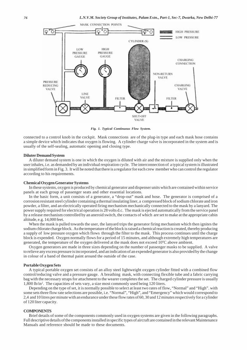
76 L.N.V.M. Society Group of Institutes, Palam Extn., Part-1, Sec-7, Dwarka, New Delhi-77
connected to a control knob in the cockpit. Mask connections are of the plug-in type and each mask hose containsa simple device which indicates that oxygen is flowing. A cylinder charge valve is incorporated in the system and isusually of the self-sealing, automatic opening and closing type.
Diluter Demand SystemA diluter demand system is one in which the oxygen is diluted with air and the mixture is supplied only when the
user inhales, i.e. as demanded by an individual respiration cycle. The interconnection of a typical system is illustratedin simplified form in Fig. 3. It will be noted that there is a regulator for each crew member who can control the regulatoraccording to his requirements.
Chemical Oxygen Generator SystemsIn these systems, oxygen is produced by chemical generator and dispenser units which are contained within service
panels at each group of passenger seats and other essential locations.In the basic form, a unit consists of a generator, a “drop-out” mask and hose. The generator is comprised of a
corrosion resistant steel cylinder containing a thermal insulating liner, a compressed block of sodium chlorate and ironpowder, a filter, and an electrically operated firing mechanism mechanically connected to the mask by a lanyard. Thepower supply required for electrical operation is 28 volts d.c. The mask is ejected automatically from the service panelby a release mechanism controlled by an aneroid switch, the contacts of which are set to make at the appropriate cabinaltitude, e.g. 14,000 feet.
When the mask is pulled towards the user, the lanyard trips the generator firing mechanism which then ignites thesodium chlorate charge block. As the temperature of the block is raised a chemical reaction is created, thereby producinga supply of low pressure oxygen which flows through the filter to the mask. This process continues until the chargeblock is expended. Oxygen normally flows for a period of 15 minutes, and although extremely high temperatures aregenerated, the temperature of the oxygen delivered at the mask does not exceed 100C above ambient.
Oxygen generators are made in three sizes depending on the number of passenger masks to be supplied. A valveto relieve any excess pressure is incorporated, and an indication of an expended generator is also provided by the changein colour of a band of thermal paint around the outside of the case.
Portable Oxygen SetsA typical portable oxygen set consists of an alloy steel lightweight oxygen cylinder fitted with a combined flow
control/reducing valve and a pressure gauge. A breathing mask, with connecting flexible tube and a fabric carryingbag with the necessary straps for attachment to the wearer completes the set. The charged cylinder pressure is usually1,800 lb/in2. The capacities of sets vary, a size most commonly used being 120 liters.
Depending on the type of set, it is normally possible to select at least two rates of flow, “Normal” and “High”. withsome sets three flow rate selections are possible, i.e. “Normal”, “High”, and “Emergency” which would correspond to2,4 and 10 litres per minute with an endurance under these flow rates of 60, 30 and 12 minutes respectively for a cylinderof 120 liter capacity.
COMPONENTSBrief details of some of the components commonly used in oxygen systems are given in the following paragraphs.
Full descriptive details of the components installed in specific types of aircraft are contained in the relevant MaintenanceManuals and reference should be made to these documents.
Fig. 1. Typical Continuous Flow System.
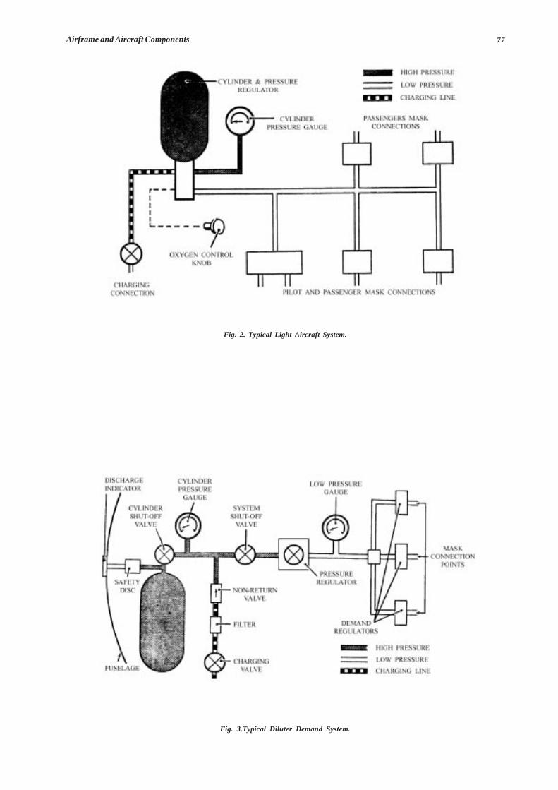
77Airframe and Aircraft Components
Fig. 2. Typical Light Aircraft System.
Fig. 3.Typical Diluter Demand System.
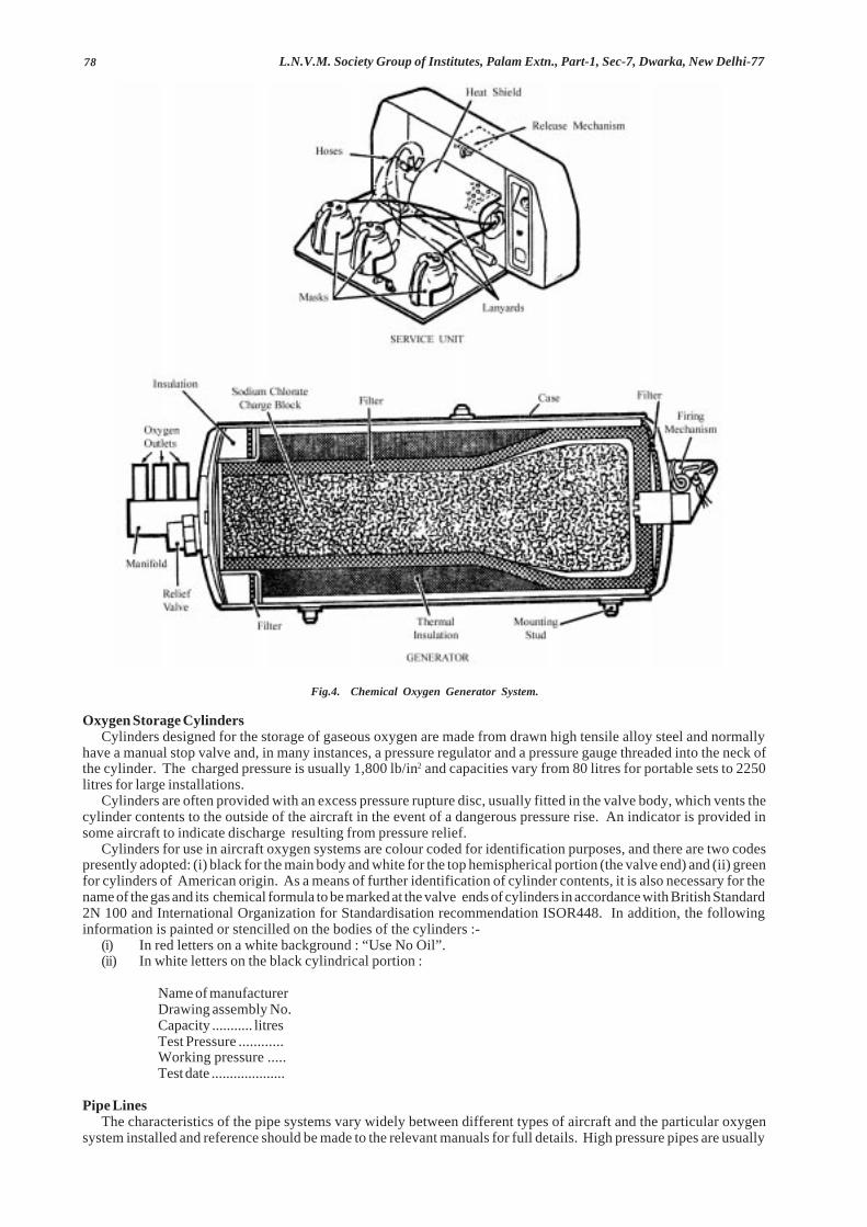
78 L.N.V.M. Society Group of Institutes, Palam Extn., Part-1, Sec-7, Dwarka, New Delhi-77
Oxygen Storage CylindersCylinders designed for the storage of gaseous oxygen are made from drawn high tensile alloy steel and normally
have a manual stop valve and, in many instances, a pressure regulator and a pressure gauge threaded into the neck ofthe cylinder. The charged pressure is usually 1,800 lb/in2 and capacities vary from 80 litres for portable sets to 2250litres for large installations.
Cylinders are often provided with an excess pressure rupture disc, usually fitted in the valve body, which vents thecylinder contents to the outside of the aircraft in the event of a dangerous pressure rise. An indicator is provided insome aircraft to indicate discharge resulting from pressure relief.
Cylinders for use in aircraft oxygen systems are colour coded for identification purposes, and there are two codespresently adopted: (i) black for the main body and white for the top hemispherical portion (the valve end) and (ii) greenfor cylinders of American origin. As a means of further identification of cylinder contents, it is also necessary for thename of the gas and its chemical formula to be marked at the valve ends of cylinders in accordance with British Standard2N 100 and International Organization for Standardisation recommendation ISOR448. In addition, the followinginformation is painted or stencilled on the bodies of the cylinders :-
(i) In red letters on a white background : “Use No Oil”.(ii) In white letters on the black cylindrical portion :
Name of manufacturerDrawing assembly No.Capacity ........... litresTest Pressure ............Working pressure .....Test date ....................
Pipe LinesThe characteristics of the pipe systems vary widely between different types of aircraft and the particular oxygen
system installed and reference should be made to the relevant manuals for full details. High pressure pipes are usually
Fig.4. Chemical Oxygen Generator System.
79Airframe and Aircraft Components
made of either stainless steel or copper-based alloys, while pipes for low pressure areas of systems are made ofaluminium-based alloys. Pipe also vary in size and some typical values are 3/16 to 1/4 inch outside diameter for highpressure pipes, and 5/16 inch outside diameter for low pressure pipes.
The types of couplings normally used for pipe joints are of the standard AGS type and MS flareless tube type.Because of the difficulty of ensuring the complete removal of flux and scale, silver soldered connections are, generally,not used.
Identification of pipes in the system by symbols and colour coding is widely used and should comply with BS 3M.23. Tie-on metal tags or metal identification rings should not be used as they may cause damage through vibration,or become detached and foul moving parts of control systems.
Non-Return ValvesThese components are designed to prevent flow reversal and are installed in a pipe line or at a connector adaptor.
Of the two basic types commonly used, one consists of a housing containing a spring-loaded valve which is forcedagainst the spring when pressure is applied to the inlet side, thus breaking the seal and allowing oxygen to flow. Whenpressure is equalised the spring returns the valve onto its seating, so preventing any reversal of oxygen flow. Theother type is a bell-mouthed hollow cylinder fitted with a captive ball in its bore. When pressure is applied at the bell-mouthed (i.e. inlet) end, the ball is forced onto the seating of a port at the opposite end and at the same time, itsdisplacement uncovers holes in the wall of the valve to allow oxygen to flow into the pipe or connection. Any tendencyfor the flow to be reversed is prevented by the oxygen forcing the ball back onto its seating at the inlet end. The normaldirection of flow for both types of valve is indicated by an arrow on the valve body.
FiltersFilters, generally of the gauze or sintered bronze type, are provided at points downstream of oxygen cylinders and
in some cases, immediately after the ground charging connection. In most systems in current use a filter, usually ofthe sintered bronze type, is normally embodied in the supply connection of a particular component, e.g. a regulatoror a reducing valve. In some instances the charging connection is counter-bored to house a slug-type sintered bronzefilter which also acts as a restrictor to guard against too rapid charging of the system.
Pressure Reducing ValvesThese valves reduce the high pressure oxygen from the storage cylinders to the pressure required in the low pressure
part of the system. In a continuous flow system the reduced pressure is supplied to the mask connection points. Ina pressure demand system the pressure from the reducing valve is comparatively higher than that for a continuousflow system and further pressure regulation is necessary at each regulator.
Design features vary considerably, but in general, reducing valves comprise a pressure reducing pre-set spring andvalve control mechanism with a relief valve to safeguard against overloads. Pressures can be reduced to the pressurerequired for a particular system.
Oxygen Diluter Demand RegulatorsThese regulators are used in crew oxygen systems and are designed to adjust the output ratio of oxygen and air
in accordance with cabin pressure and to supply, on demand, the correct air /oxygen mixture. A typical diluter demandregulator operates as follows :-
(i) With the oxygen supply “on” and “normal oxygen” selected by the appropriate control lever on the regulator,diluted oxygen in accordance with cabin altitude will be supplied to the crew member’s mask when the userinhales. The amount of air mixed with oxygen is controlled by the regulator and the air decreases with increasein cabin altitude until a cabin altitude of 32,000 feet is reached when approximately 100 per cent oxygen issupplied.
(ii) If the crew member selects “100% oxygen” the regulator air valve is closed and 100 per cent oxygen is suppliedwhen the user inhales, irrespective of cabin altitude.
(iii) If “Emergency” is selected, e.g. to provide protection against smoke and other harmful gases, a flow of 100per cent oxygen is supplied at a positive pressure to avoid any inward leakage into the mask. Dependingon the type of regulator, the oxygen may either flow only when the user inhales, or continuously andirrespective of the user’s respiration cycle.
(iv) When “Test mask” is selected oxygen is supplied at a higher pressure than that provided for the “Emergency”condition and is used for testing the masks and equipment for fit and leakage.
Supply SocketsThese components provide connections between the aircraft system and individual oxygen mask connecting tubes.
Some embody two socket points for “Normal” or “High” flow and others may have only one socket point with a flowselector lever. Calibrated orifices in the socket points of continuous flow systems control the flow rate to the masks.Socket points are made with self closing shut-off valves, spring loaded in the closed position, and open when the masktube connecting plug is inserted in the socket.
80 L.N.V.M. Society Group of Institutes, Palam Extn., Part-1, Sec-7, Dwarka, New Delhi-77
Pressure and Contents IndicatorsPressure indicators are provided to indicate cylinder pressure and, where necessary, medium and low pressure in
the supply lines. The indicators are normally of the direct-reading Burden tube type calibrated in lb/in 2, and may belocated on cylinders, pressure regulators and at oxygen system servicing panels. In aircraft requiring monitoring ofsystem high pressure at a flight engineer’s station, electrical indicating systems are also employed. These consist ofa transducer which senses high pressure and converts it to a variable electrical signal for controlling an indicator atthe flight engineer’s panel. The power supply required for operation is 28 volts d.c. and a regulating circuit isincorporated to ensure that pressure indicators are not affected by fluctuations in supply voltage.
Pressure switches are installed in the low pressure sections of some passenger oxygen systems to illuminate warninglights, thereby indicating that a system is in use. The lights are located on a cockpit overhead panel and on cabinattendants’ panels.
Contents indicators, as opposed to pressure indicators, are fitted to some types of cylinders and they are normallymarked with coloured sectors to indicate contents in terms of “FULL”, “3/4 FULL”, etc.
Oxygen MasksThere are numerous types of oxygen masks in use which vary widely in design and detailed information is outside
the scope of this Leaflet. It is important that the masks used are suitable for the particular oxygen system concerned.In general, crew masks can be fitted to the wearer’s face with minimum leakage and may be of the self-contained re-
breather type. Crew masks also contain a microphone cord and jack plug for connection into the aircraft communicationssystem. In some instances there is a requirement for pressurised aircraft to carry oxygen masks designed for theprotection of crew members in a smoke or fume laden atmosphere. These masks are of the full-face type consisting ofa transparent visor, oxygen supply hose and adjustable head straps, or of the “sweep-on” type with pre-set head strapsand/or elasticated sides. A demand regulator may also be fitted to some masks to control the flow. The hose connectionsare of the plug-in type designed for insertion into the supply sockets of a ring main system or, alternatively, a portablecylinder.
The masks provided in automatic drop-out systems for passengers are normally simple cup-shaped rubbermouldings sufficiently flexible to obviate individual fitting. They may be held in position by a simple elastic head strap,or may require holding to the face by the passenger. In non-automatic systems, the masks are usually plastic bagsfitted with a simple elastic head strap.
Flow IndicatorsOxygen flow is often indicated by a direct type of flow indicator, e.g. a float inside the transparent hose of a mask,
or by a pressure-operated blinker type of instrument.
Thermal CompensatorsThermal compensator assemblies are installed in the charging lines of some oxygen systems for the purpose of
minimising temperature build-up when oxygen, at charging pressure, flows through. A compensator consists of a brush-like wire element approximately 5 inches long, inserted into a stainless steel tube provided with connectors at each end.
There are two types of thermal compensators in use, one for connection to oxygen cylinders and the other forconnection to shut-off valves or regulators. Those fitted to oxygen cylinders have a coupling nut fitting that attachesdirect to a cylinder and the downstream end has a flare less tube connection. The second type of compensator is attachedto the component by means of a corrosion-resistant steel union through which the wire element extends. A flarelesstube connection is fitted to the upstream end.
Discharge IndicatorsIn some aircraft, discharge indicators are mounted flush to the fuselage skin in an area adjacent to the oxygen system
servicing panels. They are connected to the pressure relief lines from the oxygen cylinders and consist of a green plasticdisc which is normally retained within its holder by a circlip. In the event of an excess pressure within a cylinder thesafety valve opens and escaping oxygen will blow out the indicator disc, thereby providing a visual indication thatdischarge has occurred.
Ground Charging ValvesOxygen systems are provided with valves to permit “in-situ” charging of the cylinders from special ground servicing
units. The charging connections to the valves are normally sealed off by blanking cap nuts. A short length of chainbetween a cap nut and an adjacent part of the structure, ensures retention of the nut at the charging point locationwhen removed for charging purposes.
In some systems, the charging valve incorporates manual temperature and pressure compensation adjustmentswhich allow the system cylinder to be charged to optimum pressure at the ambient temperature in the vicinity of thecylinder. The charging rate is automatically controlled by the valve to a safe value thereby minimising the hazard ofheat build-up. A pressure/temperature correction chart is normally displayed near the charging valve for referencepurposes.
� � �
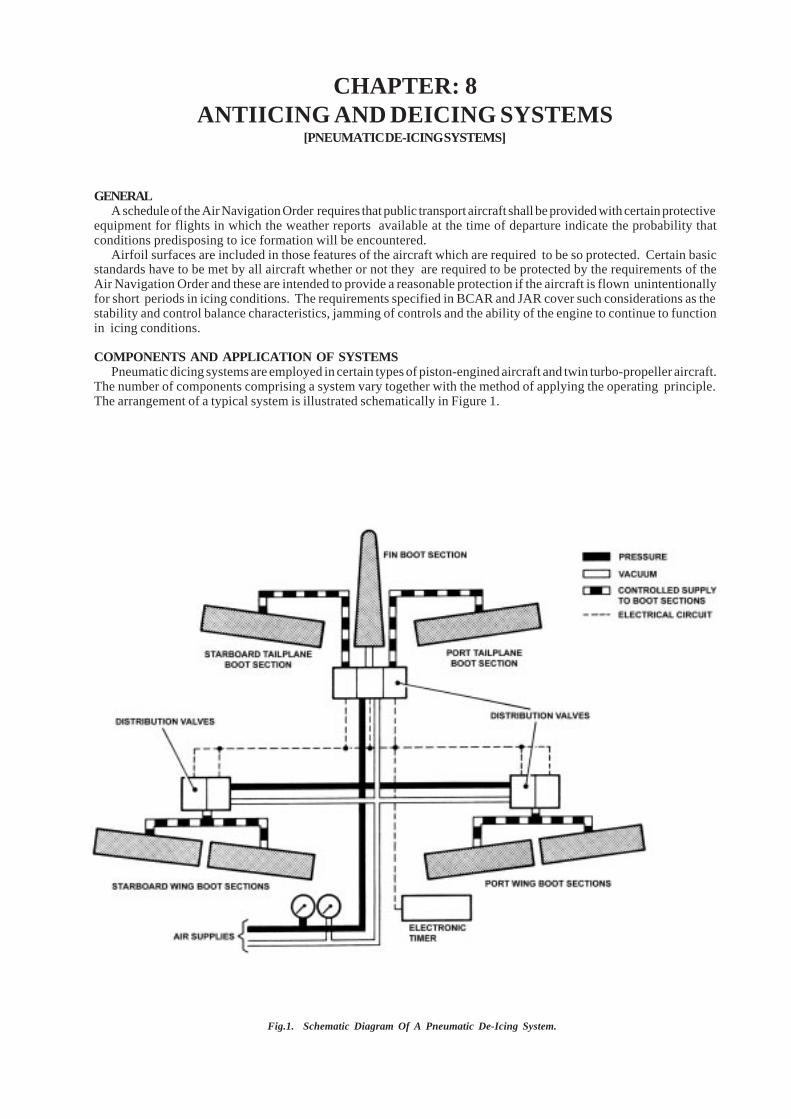
8 1Airframe and Aircraft Components
CHAPTER: 8ANTIICING AND DEICING SYSTEMS
[PNEUMATIC DE-ICING SYSTEMS]
GENERALA schedule of the Air Navigation Order requires that public transport aircraft shall be provided with certain protective
equipment for flights in which the weather reports available at the time of departure indicate the probability thatconditions predisposing to ice formation will be encountered.
Airfoil surfaces are included in those features of the aircraft which are required to be so protected. Certain basicstandards have to be met by all aircraft whether or not they are required to be protected by the requirements of theAir Navigation Order and these are intended to provide a reasonable protection if the aircraft is flown unintentionallyfor short periods in icing conditions. The requirements specified in BCAR and JAR cover such considerations as thestability and control balance characteristics, jamming of controls and the ability of the engine to continue to functionin icing conditions.
COMPONENTS AND APPLICATION OF SYSTEMSPneumatic dicing systems are employed in certain types of piston-engined aircraft and twin turbo-propeller aircraft.
The number of components comprising a system vary together with the method of applying the operating principle.The arrangement of a typical system is illustrated schematically in Figure 1.
Fig.1. Schematic Diagram Of A Pneumatic De-Icing System.
8 2 L.N.V.M. Society Group of Institutes, Palam Extn., Part-1, Sec-7, Dwarka, New Delhi-77
De-icer BootsThe de-icer boots, or overshoes, consist of layers of natural rubber and rubberised fabric between which are disposed
flat inflatable tubes closed at the ends. The tubes are made of rubberised fabric and are vulcanised inside the rubberlayers. In some boots the tubes are so arranged that when the boots are in position on a wing or tail plane leading edgethe tubes run parallel to the span; in others they run parallel to the chord. The tubes are connected to the air supplypipelines from the distribution valves system by short lengths of flexible hose secured to connectors on the boots andto the pipelines by hose clips. The external surfaces of boots are coated with a film of conductive material to bleedoff accumulations of static electricity. Depending on the type specified, a boot may be attached to a leading edge eitherby screw fasteners (rivnuts) or by cementing them directly to the leading edge.
Metal fairing strips are fitted to cover the edges of screw-fastened type boots, both on the upper and lower surfacesof an airfoil, and also at the ends of the boots. These latter strips serve to secure the ends of the boots and preventinward ‘creep’. The strips are secured by the same screws used for securing the edges of the boots to the rivnuts.
Air Supplies and DistributionThe tubes in the boot sections are inflated by air from the pressure side of an engine-driven vacuum pump, from
a high-pressure reservoir or in the case of some types of turbo-propeller aircraft, from a tapping at an engine compressorstage. At the end of an inflation stage of the operating sequence, and whenever the system is switched off, the bootsare deflated by vacuum derived from the vacuum pump or, in systems utilizing an engine compressor tapping, fromthe venturi section or an ejector nozzle.
The method of distributing air supplies to the boots depends on the de-icing systems required for a particular typeof aircraft but, in general, three methods are in use. One method employs shuttle valves which are controlled by aseparate solenoid valve; in the second method air is distributed to each boot by individual solenoid-controlled valves;in the second method air is distributed to each boot by individual solenoid-controlled valves; in the third methoddistribution is effected by a motor-driven valve.
Controls and IndicatorsThe controls and indicators required for the operation of a de-icing system depend on the type of aircraft and on
the particular arrangement of its de-icing system. In the basic arrangement, a main on-off switch, pressure and vacuumgauges or indicating lights form part of the controlling section. Pressure and vacuum is applied to the boots in analternating timed sequence and the methods adopted usually vary with the methods or air distribution. In mostinstallations, however, timing control is effected by means of an electronic device. Reference should always be madeto the relevant aircraft Maintenance Manual for details of the appropriate controlling system and time cycles.
OPERATIONWhen the system is switched on, pressure is admitted to the boot sections to inflate the tubes. The inflation weakens
the bond between ice and the boot surfaces, causing the ice to break away. At the end of the inflation stage of theoperating sequence, the air in the tubes is dumped to atmosphere through automatic opening valves and the tubesare fully deflated by the vacuum supply. This inflation and deflation cycle is repeated during the period the systemis in operation. When the system is switched off vacuum is supplied continually to all tubes of the boot sections tohold the sections flat against the wing and tail unit leading edges thus minimising aerodynamic drag.
� � �
8 3Airframe and Aircraft Components
CHAPTER: 9THERMAL (HOT GAS) DE-ICING SYSTEMS
GENERALIn systems of this type, the leading edge sections of wings and tail units are usually provided with a second inner
skin positioned to form a small gap between and the inside of the leading edge section. Heated air is ducted to the wingsand tail units and passes into the gap, providing sufficient heat in the outer skin of the leading edge to melt ice alreadyformed and prevent further ice formation. The air is exhausted to atmosphere through outlets in the skin surfaces andalso, in some cases, in the tips of wings and tail units. The temperature of the air within the ducting and leading edgesections is controlled by a shutter or butterfly type valve system the operation of which depends on the type of heatingsystem employed.
AIR SUPPLIESThere are several methods by which the heated air can be supplied and these include bleeding of air from a turbine
engine compressor, heating of ram air by passing it through a heat exchanger located in an engine exhaust gas systemand combustion heating of ram air.
In a compressor bleed system the hot air is tapped directly from a compressor stage and after mixing with a supplyof cool air in a mixing chamber it passes into the main ducting. In some systems, equipment, e.g. safety shut-off valves,is provided to ensure that an air mass flow sufficient for all de-icing requirements is supplied within pressure limitsacceptable to duct and structural limitations.
The heat exchanger method of supplying warm air is employed in some types of aircraft powered by turbo-propellerengines. The heat exchanger unit is positioned so that exhaust gases can be diverted to pass between tubes throughwhich outside air enters the main supply ducts. The supply of exhaust gases is usually regulated by a device suchas a thermostatically controlled flap fitted in the ducting between the exhaust unit and the heat exchanger.
In a combustion heating system ram air is passed through a cylindrical jacket enclosing a sealed chamber in whicha fuel/air mixture is burned, and is heated by contact with the chamber walls. Air for combustion is derived from a separateair intake and is supplied to the chamber by means of a blower.
DUCTINGThe type of ducting, materials used, methods of inter connection and disposition in an aircraft vary between de-
icing systems, and reference should therefore always be made to the relevant Aircraft Maintenance Manual for details.Light alloy and stainless steel are materials normally used in construction, stainless steel being adopted principally
in compressor bleed systems. Flanged and bolted end fittings, or band-type vee-clamps with interposed sealing ringsare common methods of connecting duct sections together, and in some cases an additional means of sliding ductsections one end into the other and securing by adjustable clamps may be adopted.
In some installations in which ducting passes through the fuselage, joints between duct sections are sealed toprevent loss of cabin air pressure. Fuselage ducting may, in some types of aircraft, comprise an inner stainless steelduct surrounded by an outer fibreglass duct. The two ducts are approximately 13 mm (1/2 in) apart and the interspaceis filled with glass wool to provide thermal insulation. The purpose of this ducting arrangement is to serve as a leakwarning system by venting interspace air through venturis which operate pressure switches and a warning light.
Expansion and contraction of ducting is catered for by bellows or gimbal type expansion joints and in aircraft havingvariable incidence tailplanes and other moveable aerofoil surfaces such as leading edge slats and Kruger flaps, swiveljoints and telescopic joints are fitted in the ducts supplying air to these surfaces.
In some installations, ducting in certain areas is lagged with a fire-resisting, heat-insulating material, normallyfibreglass held in place by glass-cloth bound with glass cord.
TEMPERATURE CONTROLThe control of the air temperature within ducting and leading edge sections is an important aspect of thermal de-
icing system operation and the methods adopted depend on the type of system.In a typical compressor bleed system, control is effected by temperature sensing units which are located at various
points in the leading edge ducting and by valves in the main air supply ducting. The sensing units and valves areelectrically interconnected so that the valves are automatically positioned to regulate the flow of heated air to the systemthus maintaining the temperature within a predetermined range. Indications of air temperature conditions are providedby resistance type temperature sensing elements and indicators, temperature sensitive switches and overheat warninglights. On some aircraft the electrical supplies to the valves are interrupted by landing gear controlled relays when theaircraft is on the ground. Under these conditions, valve operation is accomplished by holding the system control switchto a ‘TEST’ position.
When heat exchangers are employed, temperature control is usually obtained by the use of adjustable flaps andvalves to decrease or increase the supply of heating and cooling air passed across the exchangers. The method ofcontrolling the flaps and valves varies with different aircraft but a typical system incorporates an electric actuator,which is operated automatically by an inching device controlled by a temperature sensing element fitted in the ducton the warm air outlet side of the heat exchanger. In some systems, actuators are directly controlled by thermal switches,

8 4 L.N.V.M. Society Group of Institutes, Palam Extn., Part-1, Sec-7, Dwarka, New Delhi-77
so that the flaps or valves are automatically closed when a predetermined temperature is reached. Indications of airtemperature conditions are provided by resistance type temperature sensing elements and indicators, temperaturesensitive switches and overheat warning lights.
In systems incorporating combustion heaters, the temperature is usually controlled by thermal cyclic switcheslocated in the heater outlet ducts, so that when the temperature reaches a predetermined maximum the fuel supply tothe heaters is automatically switched off.
� � �
8 5Airframe and Aircraft Components
CHAPTER: 10GROUND DE-ICING OF AIRCRAFT
GENERALThe presence of frozen deposits on an aircraft may be the result of direct precipitation (rain, snow, frost etc.,) or
accretion of frost or ice on external surfaces of integral fuel tanks after prolonged flight at high altitude, or accumulationson the landing gear and forward surfaces or undersurfaces following taxying through snow or slush.
Any deposits of ice, snow or frost on the external surfaces of an aircraft may drastically affect its performance. Thiscan be due to reduced aerodynamic lift and increased aerodynamic drag resulting from the disturbed airflow over theaerofoil surfaces, or due to the weight of the deposit over the whole aircraft. The operation of an aircraft may also beseriously affected by the freezing of moisture in controls, hinges and microswitches, or by the ingestion of ice into theengine. Furthermore, since the in-flight de-icing system may not become effective until the aircraft is established inthe climbout, the measures taken to remove frozen deposits on the ground must also be such as to provide adequateprotection during the initial stages of flight.
Neither the use of currently available Freezing Point Depressant (FPD) types of de-icing/anti-icing compounds, northe use of manual techniques of de-icing with such compounds should be thought of as producing reliable anti-icingqualities for a define period of time because the number of variables involved make it impractical to estimate that time.Only in the sense that under certain conditions FPD anti-icing compounds are known to be effective in retarding theformation of frost, snow or ice may they be considered to have anti-icing qualities for a period of time thus making theprocess of de-icing simpler and in many cases obviating the need for further de-icing or treatment during that period.It is emphasised, however, that the need for a close inspection of an aircraft prior to take-off still remains.
The aircraft de-icing systems are designed to remove or prevent the accretion of ice on a specific area of the wings,tail and engine nacelles in flight and would not normally be effective in removing deposits which have accumulatedwhile the aircraft is stationary. Their use on the ground may, in some instances, also cause a different type of stationary.Their use on the ground may, in some instances, also cause a different type of unsatisfactory situation by melting partsof the deposit which would then freeze elsewhere. The use of cabin heating to remove deposits from the fuselage isalso not recommended for the same reason.
When aircraft are moved so as to be under cover during inclement weather, any melted snow or ice may freeze againwhen the aircraft is subsequently moved into sub-zero temperatures. Complete protection could be provided by placingaircraft in heated hangers, but due to the size of modern transport aircraft and the need to meet schedules involvingquick turnround times this is not often practicable. Removal of frost, ice and snow from aircraft is therefore oftennecessary and maintenance crews need to be familiar with the methods of ground de-icing in current use.
There are two main types of de-icing/anti-icing fluids:-
(a) Type I fluids (unthickened). These fluids have a high glycol content and a low viscosity. The de-icing performanceis good, however, the provide only limited protection against refreezing.
(b) Type II fluids (thickened). These fluids have a minimum glycol content of approximately 50% and due to thethickening agent have special properties which enable the fluid to remain on the aircraft surfaces until take-off.The de-icing performance is good and, in addition, protection is provided against refreezing and/or build-up offurther accretions, when exposed to freezing precipitation.
� � �
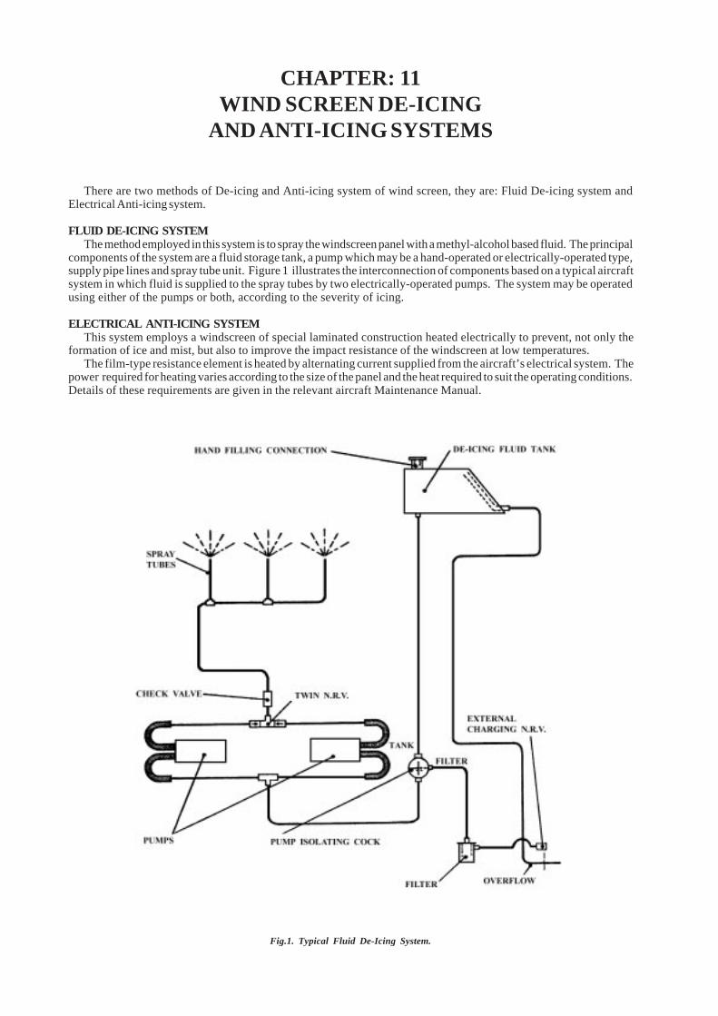
8 6 L.N.V.M. Society Group of Institutes, Palam Extn., Part-1, Sec-7, Dwarka, New Delhi-77
CHAPTER: 11WIND SCREEN DE-ICING
AND ANTI-ICING SYSTEMS
There are two methods of De-icing and Anti-icing system of wind screen, they are: Fluid De-icing system andElectrical Anti-icing system.
FLUID DE-ICING SYSTEMThe method employed in this system is to spray the windscreen panel with a methyl-alcohol based fluid. The principal
components of the system are a fluid storage tank, a pump which may be a hand-operated or electrically-operated type,supply pipe lines and spray tube unit. Figure 1 illustrates the interconnection of components based on a typical aircraftsystem in which fluid is supplied to the spray tubes by two electrically-operated pumps. The system may be operatedusing either of the pumps or both, according to the severity of icing.
ELECTRICAL ANTI-ICING SYSTEMThis system employs a windscreen of special laminated construction heated electrically to prevent, not only the
formation of ice and mist, but also to improve the impact resistance of the windscreen at low temperatures.The film-type resistance element is heated by alternating current supplied from the aircraft’s electrical system. The
power required for heating varies according to the size of the panel and the heat required to suit the operating conditions.Details of these requirements are given in the relevant aircraft Maintenance Manual.
Fig.1. Typical Fluid De-Icing System.
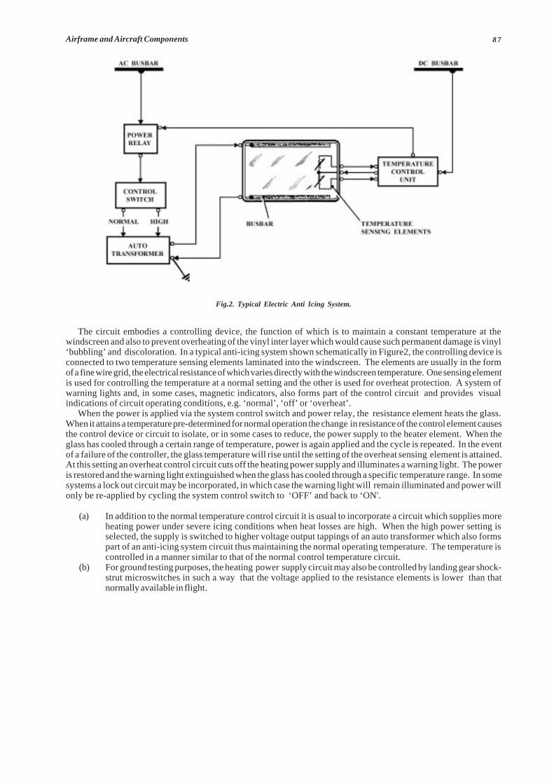
8 7Airframe and Aircraft Components
The circuit embodies a controlling device, the function of which is to maintain a constant temperature at thewindscreen and also to prevent overheating of the vinyl inter layer which would cause such permanent damage is vinyl‘bubbling’ and discoloration. In a typical anti-icing system shown schematically in Figure2, the controlling device isconnected to two temperature sensing elements laminated into the windscreen. The elements are usually in the formof a fine wire grid, the electrical resistance of which varies directly with the windscreen temperature. One sensing elementis used for controlling the temperature at a normal setting and the other is used for overheat protection. A system ofwarning lights and, in some cases, magnetic indicators, also forms part of the control circuit and provides visualindications of circuit operating conditions, e.g. ‘normal’, ‘off’ or ‘overheat’.
When the power is applied via the system control switch and power relay, the resistance element heats the glass.When it attains a temperature pre-determined for normal operation the change in resistance of the control element causesthe control device or circuit to isolate, or in some cases to reduce, the power supply to the heater element. When theglass has cooled through a certain range of temperature, power is again applied and the cycle is repeated. In the eventof a failure of the controller, the glass temperature will rise until the setting of the overheat sensing element is attained.At this setting an overheat control circuit cuts off the heating power supply and illuminates a warning light. The poweris restored and the warning light extinguished when the glass has cooled through a specific temperature range. In somesystems a lock out circuit may be incorporated, in which case the warning light will remain illuminated and power willonly be re-applied by cycling the system control switch to ‘OFF’ and back to ‘ON'.
(a) In addition to the normal temperature control circuit it is usual to incorporate a circuit which supplies moreheating power under severe icing conditions when heat losses are high. When the high power setting isselected, the supply is switched to higher voltage output tappings of an auto transformer which also formspart of an anti-icing system circuit thus maintaining the normal operating temperature. The temperature iscontrolled in a manner similar to that of the normal control temperature circuit.
(b) For ground testing purposes, the heating power supply circuit may also be controlled by landing gear shock-strut microswitches in such a way that the voltage applied to the resistance elements is lower than thatnormally available in flight.
� � �
Fig.2. Typical Electric Anti Icing System.
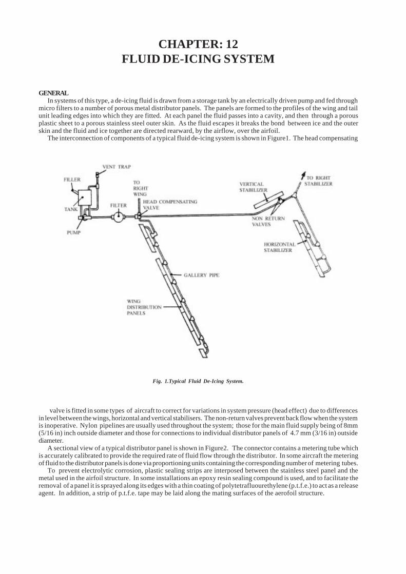
8 8 L.N.V.M. Society Group of Institutes, Palam Extn., Part-1, Sec-7, Dwarka, New Delhi-77
CHAPTER: 12FLUID DE-ICING SYSTEM
GENERALIn systems of this type, a de-icing fluid is drawn from a storage tank by an electrically driven pump and fed through
micro filters to a number of porous metal distributor panels. The panels are formed to the profiles of the wing and tailunit leading edges into which they are fitted. At each panel the fluid passes into a cavity, and then through a porousplastic sheet to a porous stainless steel outer skin. As the fluid escapes it breaks the bond between ice and the outerskin and the fluid and ice together are directed rearward, by the airflow, over the airfoil.
The interconnection of components of a typical fluid de-icing system is shown in Figure1. The head compensating
Fig. 1.Typical Fluid De-Icing System.
valve is fitted in some types of aircraft to correct for variations in system pressure (head effect) due to differencesin level between the wings, horizontal and vertical stabilisers. The non-return valves prevent back flow when the systemis inoperative. Nylon pipelines are usually used throughout the system; those for the main fluid supply being of 8mm(5/16 in) inch outside diameter and those for connections to individual distributor panels of 4.7 mm (3/16 in) outsidediameter.
A sectional view of a typical distributor panel is shown in Figure2. The connector contains a metering tube whichis accurately calibrated to provide the required rate of fluid flow through the distributor. In some aircraft the meteringof fluid to the distributor panels is done via proportioning units containing the corresponding number of metering tubes.
To prevent electrolytic corrosion, plastic sealing strips are interposed between the stainless steel panel and themetal used in the airfoil structure. In some installations an epoxy resin sealing compound is used, and to facilitate theremoval of a panel it is sprayed along its edges with a thin coating of polytetrafluourethylene (p.t.f.e.) to act as a releaseagent. In addition, a strip of p.t.f.e. tape may be laid along the mating surfaces of the aerofoil structure.
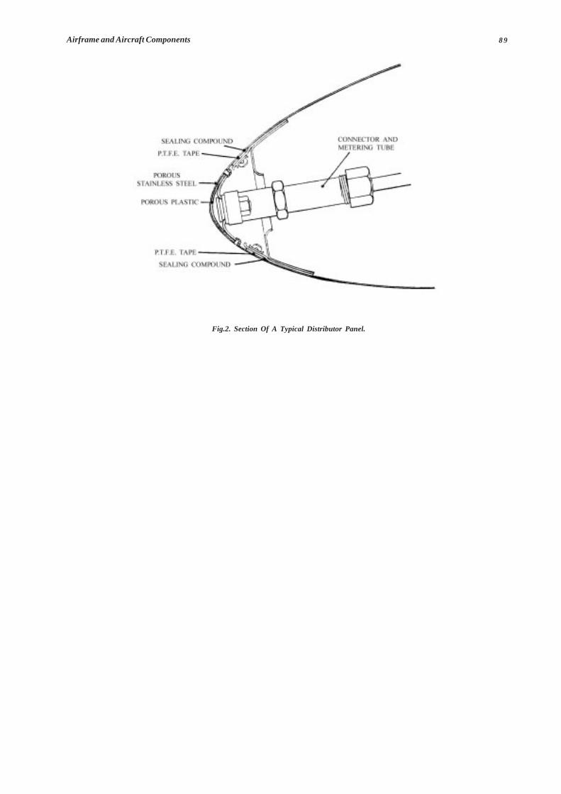
8 9Airframe and Aircraft Components
Fig.2. Section Of A Typical Distributor Panel.
� � �� � �� � �� � �� � �
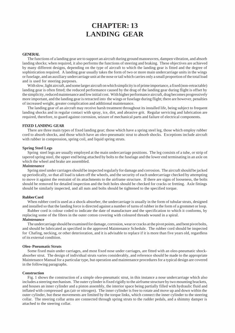
9 0 L.N.V.M. Society Group of Institutes, Palam Extn., Part-1, Sec-7, Dwarka, New Delhi-77
CHAPTER: 13LANDING GEAR
GENERALThe functions of a landing gear are to support an aircraft during ground manoeuvres, dampen vibration, and absorb
landing shocks; when required, it also performs the functions of steering and braking. These objectives are achievedby many different designs, depending on the type of aircraft to which the landing gear is fitted and the degree ofsophistication required. A landing gear usually takes the form of two or more main undercarriage units in the wingsor fuselage, and an auxiliary undercarriage unit at the nose or tail which carries only a small proportion of the total loadand is used for steering purposes.
With slow, light aircraft, and some larger aircraft on which simplicity is of prime importance, a fixed (non-retractable)landing gear is often fitted; the reduced performance caused by the drag of the landing gear during flight is offset bythe simplicity, reduced maintenance and low initial cost. With higher performance aircraft, drag becomes progressivelymore important, and the landing gear is retracted into the wings or fuselage during flight; there are however, penaltiesof increased weight, greater complication and additional maintenance.
The landing gear of an aircraft may receive harsh treatment throughout its installed life, being subject to frequentlanding shocks and in regular contact with spray, ice, dirt, and abrasive grit. Regular servicing and lubrication arerequired, therefore, to guard against corrosion, seizure of mechanical parts and failure of electrical components.
FIXED LANDING GEARThere are three main types of fixed landing gear; those which have a spring steel leg, those which employ rubber
cord to absorb shocks, and those which have an oleo-pneumatic strut to absorb shocks. Exceptions include aircraftwith rubber in compression, spring coil, and liquid spring struts.
Spring Steel LegsSpring steel legs are usually employed at the main undercarriage positions. The leg consists of a tube, or strip of
tapered spring steel, the upper end being attached by bolts to the fuselage and the lower end terminating in an axle onwhich the wheel and brake are assembled.Maintenance
Spring steel under carriages should be inspected regularly for damage and corrosion. The aircraft should be jackedup periodically, so that all load is taken off the wheels, and the security of each undercarriage checked by attemptingto move it against the restraint of its attachments to the airframe structure. If there are signs of looseness, the boltsshould be removed for detailed inspection and the bolt holes should be checked for cracks or fretting. Axle fittingsshould be similarly inspected, and all nuts and bolts should be tightened to the specified torque.
Rubber CordWhen rubber cord is used as a shock-absorber, the undercarriage is usually in the form of tubular struts, designed
and installed so that the landing force is directed against a number of turns of rubber in the form of a grommet or loop.Rubber cord is colour coded to indicate the date of manufacture and the specification to which it conforms, by
replacing some of the fibres in the outer cotton covering with coloured threads wound in a spiral.Maintenance
The undercarriage should be examined for damage, corrosion, wear or cracks at the pivot points, and bent pivot bolts,and should be lubricated as specified in the approved Maintenance Schedule. The rubber cord should be inspectedfor Chafing, necking, or other deterioration, and it is advisable to replace if it is more than five years old, regardlessof its external condition.
Oleo- Pneumatic StrutsSome fixed main under carriages, and most fixed nose under carriages, are fitted with an oleo-pneumatic shock-
absorber strut. The design of individual struts varies considerably, and reference should be made to the appropriateMaintenance Manual for a particular type, but operation and maintenance procedures for a typical design are coveredin the following paragraphs.
ConstructionFig. 1 shows the construction of a simple oleo-pneumatic strut, in this instance a nose undercarriage which also
includes a steering mechanism. The outer cylinder is fixed rigidly to the airframe structure by two mounting brackets,and houses an inner cylinder and a piston assembly, the interior space being partially filled with hydraulic fluid andinflated with compressed gas (air or nitrogen). The inner cylinder is free to rotate and move up and down within theouter cylinder, but these movements are limited by the torque links, which connect the inner cylinder to the steeringcollar. The steering collar arms are connected through spring struts to the rudder pedals, and a shimmy damper isattached to the steering collar.
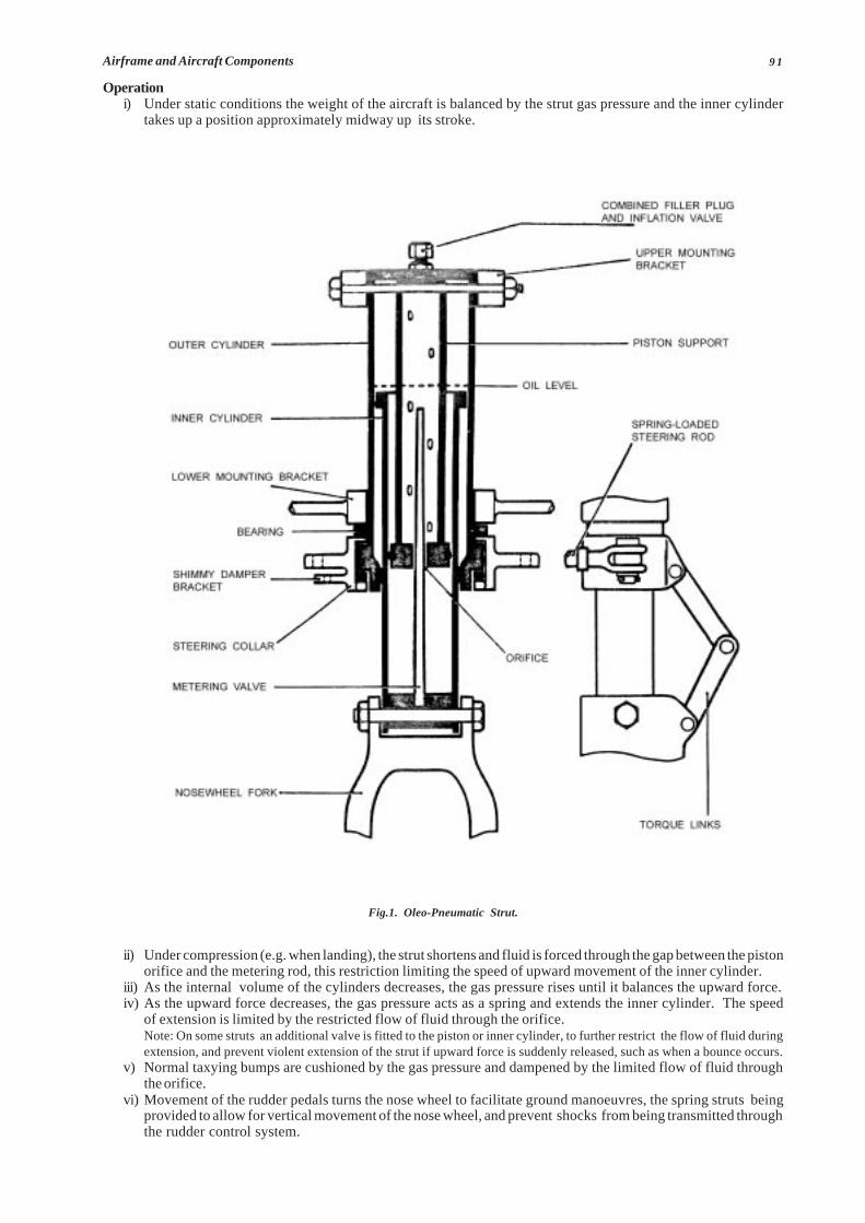
9 1Airframe and Aircraft Components
Operationi) Under static conditions the weight of the aircraft is balanced by the strut gas pressure and the inner cylinder
takes up a position approximately midway up its stroke.
Fig.1. Oleo-Pneumatic Strut.
ii) Under compression (e.g. when landing), the strut shortens and fluid is forced through the gap between the pistonorifice and the metering rod, this restriction limiting the speed of upward movement of the inner cylinder.
iii) As the internal volume of the cylinders decreases, the gas pressure rises until it balances the upward force.iv) As the upward force decreases, the gas pressure acts as a spring and extends the inner cylinder. The speed
of extension is limited by the restricted flow of fluid through the orifice.Note: On some struts an additional valve is fitted to the piston or inner cylinder, to further restrict the flow of fluid duringextension, and prevent violent extension of the strut if upward force is suddenly released, such as when a bounce occurs.
v) Normal taxying bumps are cushioned by the gas pressure and dampened by the limited flow of fluid throughthe orifice.
vi) Movement of the rudder pedals turns the nose wheel to facilitate ground manoeuvres, the spring struts beingprovided to allow for vertical movement of the nose wheel, and prevent shocks from being transmitted throughthe rudder control system.
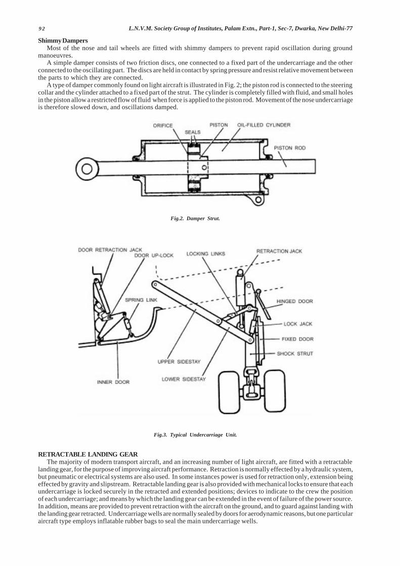
9 2 L.N.V.M. Society Group of Institutes, Palam Extn., Part-1, Sec-7, Dwarka, New Delhi-77
Shimmy DampersMost of the nose and tail wheels are fitted with shimmy dampers to prevent rapid oscillation during ground
manoeuvres.A simple damper consists of two friction discs, one connected to a fixed part of the undercarriage and the other
connected to the oscillating part. The discs are held in contact by spring pressure and resist relative movement betweenthe parts to which they are connected.
A type of damper commonly found on light aircraft is illustrated in Fig. 2; the piston rod is connected to the steeringcollar and the cylinder attached to a fixed part of the strut. The cylinder is completely filled with fluid, and small holesin the piston allow a restricted flow of fluid when force is applied to the piston rod. Movement of the nose undercarriageis therefore slowed down, and oscillations damped.
Fig.2. Damper Strut.
Fig.3. Typical Undercarriage Unit.
RETRACTABLE LANDING GEARThe majority of modern transport aircraft, and an increasing number of light aircraft, are fitted with a retractable
landing gear, for the purpose of improving aircraft performance. Retraction is normally effected by a hydraulic system,but pneumatic or electrical systems are also used. In some instances power is used for retraction only, extension beingeffected by gravity and slipstream. Retractable landing gear is also provided with mechanical locks to ensure that eachundercarriage is locked securely in the retracted and extended positions; devices to indicate to the crew the positionof each undercarriage; and means by which the landing gear can be extended in the event of failure of the power source.In addition, means are provided to prevent retraction with the aircraft on the ground, and to guard against landing withthe landing gear retracted. Undercarriage wells are normally sealed by doors for aerodynamic reasons, but one particularaircraft type employs inflatable rubber bags to seal the main undercarriage wells.
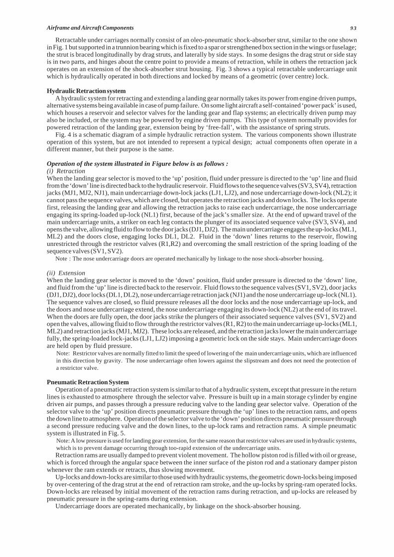
9 3Airframe and Aircraft Components
Retractable under carriages normally consist of an oleo-pneumatic shock-absorber strut, similar to the one shownin Fig. 1 but supported in a trunnion bearing which is fixed to a spar or strengthened box section in the wings or fuselage;the strut is braced longitudinally by drag struts, and laterally by side stays. In some designs the drag strut or side stayis in two parts, and hinges about the centre point to provide a means of retraction, while in others the retraction jackoperates on an extension of the shock-absorber strut housing. Fig. 3 shows a typical retractable undercarriage unitwhich is hydraulically operated in both directions and locked by means of a geometric (over centre) lock.
Hydraulic Retraction systemA hydraulic system for retracting and extending a landing gear normally takes its power from engine driven pumps,
alternative systems being available in case of pump failure. On some light aircraft a self-contained ‘power pack’ is used,which houses a reservoir and selector valves for the landing gear and flap systems; an electrically driven pump mayalso be included, or the system may be powered by engine driven pumps. This type of system normally provides forpowered retraction of the landing gear, extension being by ‘free-fall’, with the assistance of spring struts.
Fig. 4 is a schematic diagram of a simple hydraulic retraction system. The various components shown illustrateoperation of this system, but are not intended to represent a typical design; actual components often operate in adifferent manner, but their purpose is the same.
Operation of the system illustrated in Figure below is as follows :(i) RetractionWhen the landing gear selector is moved to the ‘up’ position, fluid under pressure is directed to the ‘up’ line and fluidfrom the ‘down’ line is directed back to the hydraulic reservoir. Fluid flows to the sequence valves (SV3, SV4), retractionjacks (MJ1, MJ2, NJ1), main undercarriage down-lock jacks (LJ1, LJ2), and nose undercarriage down-lock (NL2); itcannot pass the sequence valves, which are closed, but operates the retraction jacks and down locks. The locks operatefirst, releasing the landing gear and allowing the retraction jacks to raise each undercarriage, the nose undercarriageengaging its spring-loaded up-lock (NL1) first, because of the jack’s smaller size. At the end of upward travel of themain undercarriage units, a striker on each leg contacts the plunger of its associated sequence valve (SV3, SV4), andopens the valve, allowing fluid to flow to the door jacks (DJ1, DJ2). The main undercarriage engages the up-locks (ML1,ML2) and the doors close, engaging locks DL1, DL2. Fluid in the ‘down’ lines returns to the reservoir, flowingunrestricted through the restrictor valves (R1,R2) and overcoming the small restriction of the spring loading of thesequence valves (SV1, SV2).
Note : The nose undercarriage doors are operated mechanically by linkage to the nose shock-absorber housing.
(ii) ExtensionWhen the landing gear selector is moved to the ‘down’ position, fluid under pressure is directed to the ‘down’ line,and fluid from the ‘up’ line is directed back to the reservoir. Fluid flows to the sequence valves (SV1, SV2), door jacks(DJ1, DJ2), door locks (DL1, DL2), nose undercarriage retraction jack (NJ1) and the nose undercarriage up-lock (NL1).The sequence valves are closed, so fluid pressure releases all the door locks and the nose undercarriage up-lock, andthe doors and nose undercarriage extend, the nose undercarriage engaging its down-lock (NL2) at the end of its travel.When the doors are fully open, the door jacks strike the plungers of their associated sequence valves (SV1, SV2) andopen the valves, allowing fluid to flow through the restrictor valves (R1, R2) to the main undercarriage up-locks (ML1,ML2) and retraction jacks (MJ1, MJ2). These locks are released, and the retraction jacks lower the main undercarriagefully, the spring-loaded lock-jacks (LJ1, LJ2) imposing a geometric lock on the side stays. Main undercarriage doorsare held open by fluid pressure.
Note: Restrictor valves are normally fitted to limit the speed of lowering of the main undercarriage units, which are influencedin this direction by gravity. The nose undercarriage often lowers against the slipstream and does not need the protection ofa restrictor valve.
Pneumatic Retraction SystemOperation of a pneumatic retraction system is similar to that of a hydraulic system, except that pressure in the return
lines is exhausted to atmosphere through the selector valve. Pressure is built up in a main storage cylinder by enginedriven air pumps, and passes through a pressure reducing valve to the landing gear selector valve. Operation of theselector valve to the ‘up’ position directs pneumatic pressure through the ‘up’ lines to the retraction rams, and opensthe down line to atmosphere. Operation of the selector valve to the ‘down’ position directs pneumatic pressure througha second pressure reducing valve and the down lines, to the up-lock rams and retraction rams. A simple pneumaticsystem is illustrated in Fig. 5.
Note: A low pressure is used for landing gear extension, for the same reason that restrictor valves are used in hydraulic systems,which is to prevent damage occurring through too-rapid extension of the undercarriage units.Retraction rams are usually damped to prevent violent movement. The hollow piston rod is filled with oil or grease,
which is forced through the angular space between the inner surface of the piston rod and a stationary damper pistonwhenever the ram extends or retracts, thus slowing movement.
Up-locks and down-locks are similar to those used with hydraulic systems, the geometric down-locks being imposedby over-centering of the drag strut at the end of retraction ram stroke, and the up-locks by spring-ram operated locks.Down-locks are released by initial movement of the retraction rams during retraction, and up-locks are released bypneumatic pressure in the spring-rams during extension.
Undercarriage doors are operated mechanically, by linkage on the shock-absorber housing.
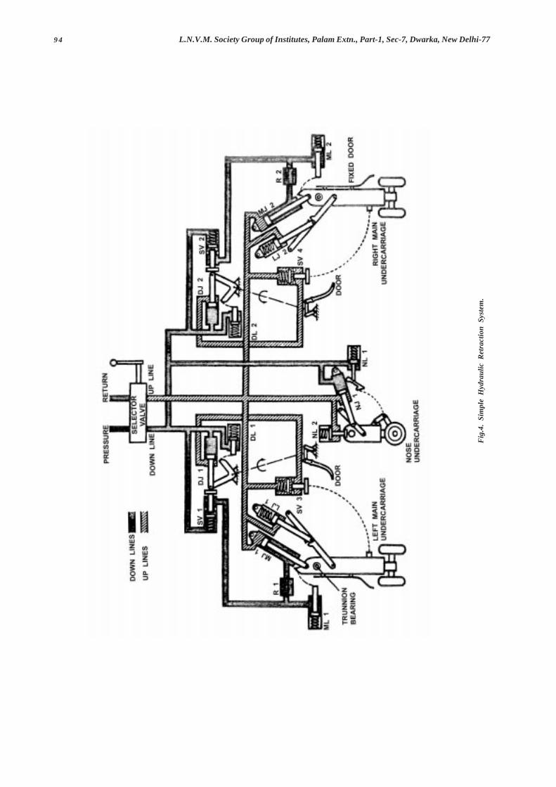
9 4 L.N.V.M. Society Group of Institutes, Palam Extn., Part-1, Sec-7, Dwarka, New Delhi-77
Fig
.4.
Sim
ple
Hyd
raul
ic R
etra
ctio
n S
yste
m.
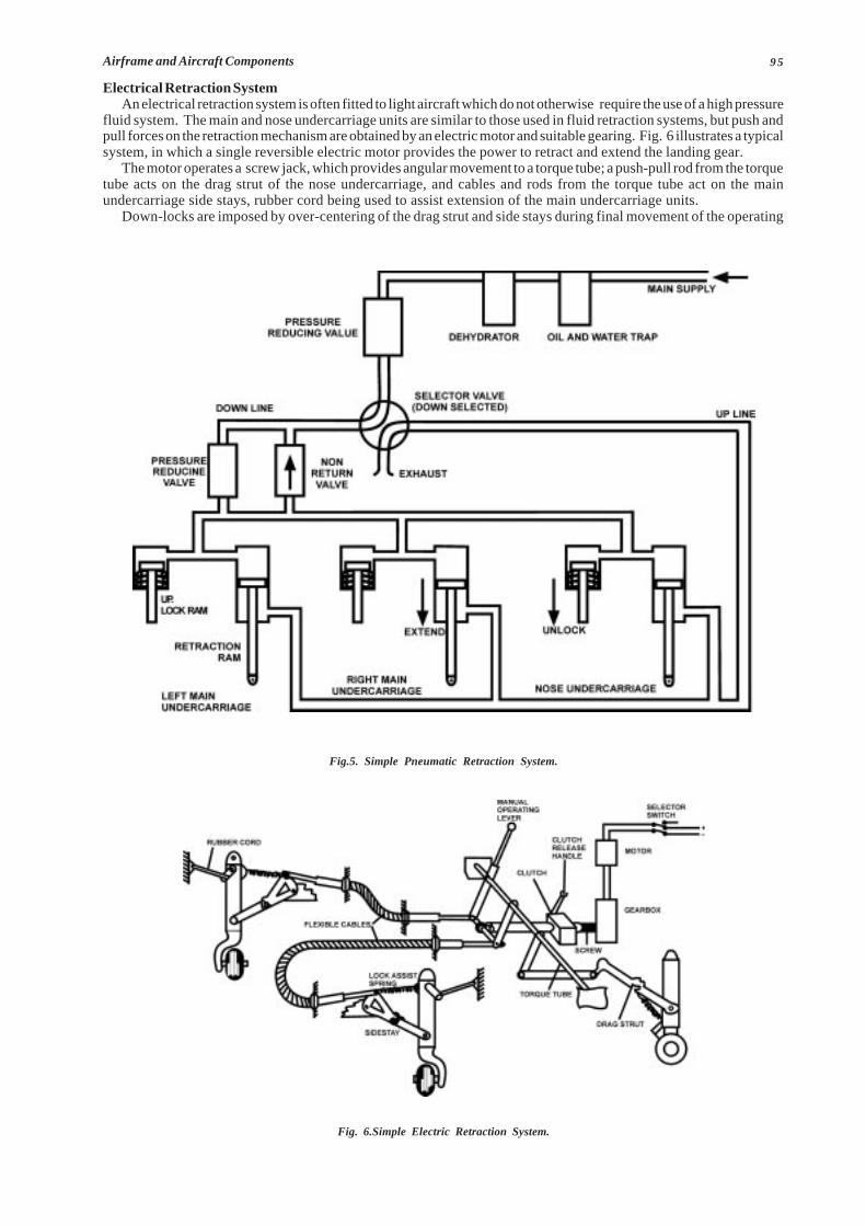
9 5Airframe and Aircraft Components
Electrical Retraction SystemAn electrical retraction system is often fitted to light aircraft which do not otherwise require the use of a high pressure
fluid system. The main and nose undercarriage units are similar to those used in fluid retraction systems, but push andpull forces on the retraction mechanism are obtained by an electric motor and suitable gearing. Fig. 6 illustrates a typicalsystem, in which a single reversible electric motor provides the power to retract and extend the landing gear.
The motor operates a screw jack, which provides angular movement to a torque tube; a push-pull rod from the torquetube acts on the drag strut of the nose undercarriage, and cables and rods from the torque tube act on the mainundercarriage side stays, rubber cord being used to assist extension of the main undercarriage units.
Down-locks are imposed by over-centering of the drag strut and side stays during final movement of the operating
Fig.5. Simple Pneumatic Retraction System.
Fig. 6.Simple Electric Retraction System.
9 6 L.N.V.M. Society Group of Institutes, Palam Extn., Part-1, Sec-7, Dwarka, New Delhi-77
mechanism, with the assistance of springs. Limit switches on the drag strut and side stays cut off electrical power andbrake the motor switches on the drag strut and side stays cut off electrical power and brake the motor when the down-locks have engaged, while a limit switch on the torque tube stops and brakes the motor when the landing gear is fullyretracted.
Undercarriage doors are operated by linkage go the shock-absorber housings.
Position IndicationAlthough the landing gear, when selected down, may be visible from the crew compartment, it is not usually possible
to be certain that each undercarriage is securely locked. An electrical indicating system is used to provide a positiveindication to the crew of the operation of the locks and of the position of the landing gear. The system usually consistsof micro switches on the up-locks and down-locks, which make or break when the locks operate, and which are connectedto a landing gear position indicator on the instrument panel. A mechanical indicator may also be provided, to showthat the landing gear is down and locked when the electrical system is inoperative. On British manufactured aircraft,the electrical undercarriage indicating system operates in such a manner that a green light is displayed when theundercarriage is locked down, a red light is displayed when the undercarriage is in transit, and no lights are visible whenthe undercarriage is locked up; bulbs are usually duplicated to avoid the possibility of false indications as a result ofbulb failures. On other aircraft, similar indications may be obtained by the use of magnetic indicators or lights, but onsome light aircraft a single green light indicates that all under carriages are locked down, and an amber light indicatesthat all under carriages are locked up. On some transport aircraft, provision is also made for the crew to examine thelocks during flight in the event of failure or incorrect operation of the indicating system. Whichever indicating systemis used, it is important that the micro switches are adjusted so that operation of the lights coincides with thecorresponding position of the landing gear.
Safety FeaturesSince the correct operation of the landing gear is of the utmost importance, a number of safety features are included
in the retraction system to ensure its correct operation under all conditions.
Nose-wheel CenteringTo avoid damage to the airframe structure, the nose wheel must always be aligned in a fore and aft direction during
retraction, and a number of methods are used to ensure that this happens automatically. One method utilizes a camand cam track between the inner and outer cylinders on the shock-absorber. The cam is fixed to the top of the innercylinder, and the track to the bottom of the outer cylinder. As the strut extends under internal gas pressure after take-off, the cam engages the track and centres the nose undercarriage before it retracts. A second method is the use ofa peg located at the top of the shock-absorber strut, which engages a track fixed to the strut housing or in the wheelbay, and this device centres the undercarriage as it retracts. Hydraulic nose wheel centering on aircraft with poweredsteering will be discussed later in this chapter.
Selector LockTo prevent inadvertent retraction of the landing gear when the aircraft is resting on its wheels, a safety device is
incorporated which prevents movement of the selector lever; mechanical ground locks are also provided for servicingpurposes. The safety lock consists of a spring-loaded plunger which retains the selector in the down position landis released by the operation of a solenoid. Electrical power to the solenoid is controlled by a switch mounted on theshock-absorber strut; when the strut is compressed the switch is open, but as the strut extends after take-off, the switchcontacts close and the electrical supply to the solenoid is completed, thus releasing the selector lever lock and allowingthe landing gear to be selected up. A means of overriding the lock, such as a separate gated switch to complete thecircuit, or a mechanical means of avoiding the locking plunger, is provided for emergency use and for maintenancepurposes.
Warning DevicesTo guard against landing with the landing gear retracted or unlocked, a warning horn is incorporated in the system
and connected to a throttle-operated switch. If one or more throttle levers are less than approximately one third open,as would be the case during approach to land, the horn sounds and the red warning lamp illuminates if the landing gearis in any position other than down and locked. A horn isolation switch is often provided to allow certain flight exercisesand ground servicing operations to be carried out without hindrance.
Emergency ExtensionA means of extending the landing gear and locking it in the down position is provided to cater for the eventuality
of main system failure. On some aircraft the up-locks are released manually or by means of an emergency pneumaticsystem; the landing gear ‘free-falls’ under its own weight and the down locks are engaged by spring jacks. On otheraircraft the landing gear is extended by an emergency pressure system which often uses alternative pipelines to thejacks. Pressure for the emergency system may be supplied by a hydraulic accumulator, a hand pump, a pneumatic storagecylinder, or an electrically powered pump.
POWERED STEERINGLight aircraft generally employ a simple steering system, in which the nose wheel is mechanically linked to the rudder
pedals. Larger aircraft require powered steering arrangements, in which the nose wheel is turned by hydraulic,
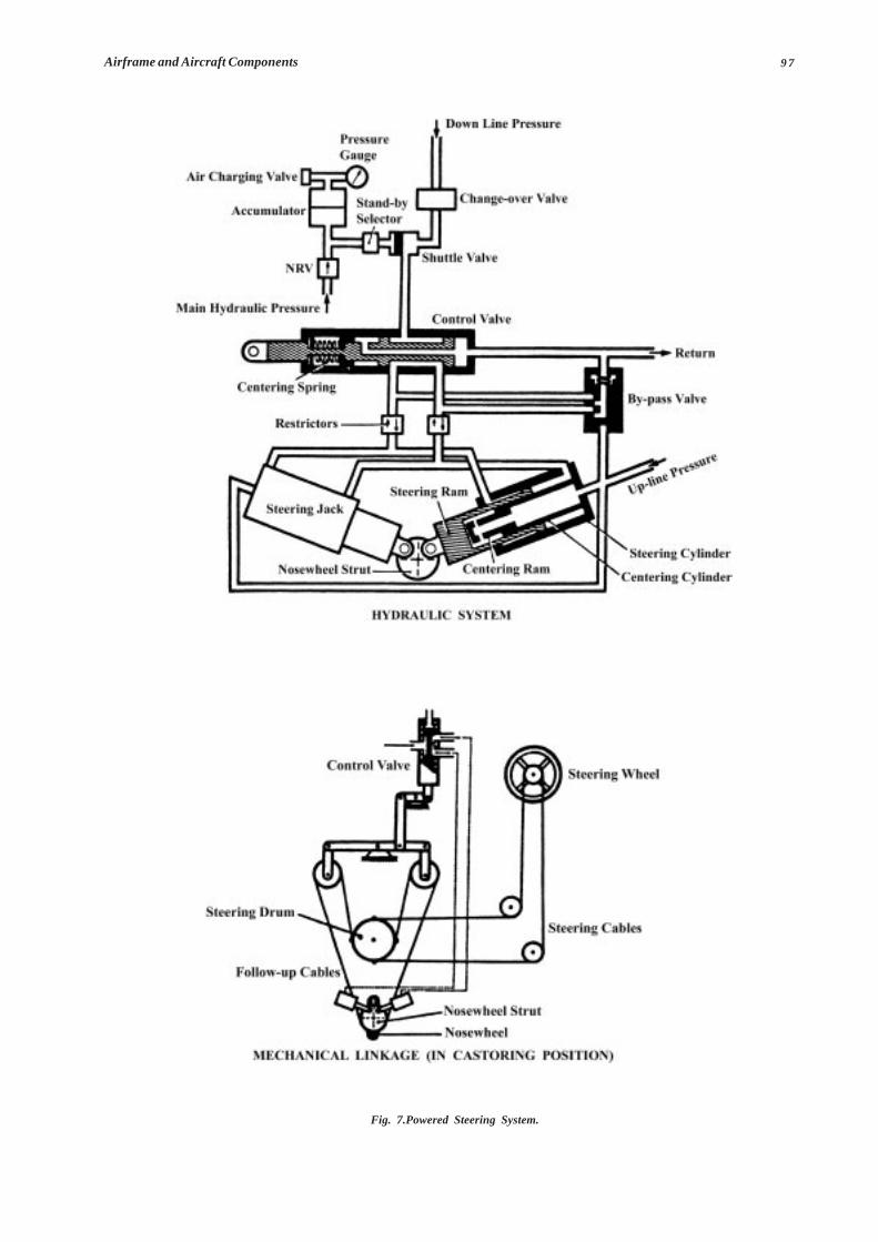
9 7Airframe and Aircraft Components
Fig. 7.Powered Steering System.
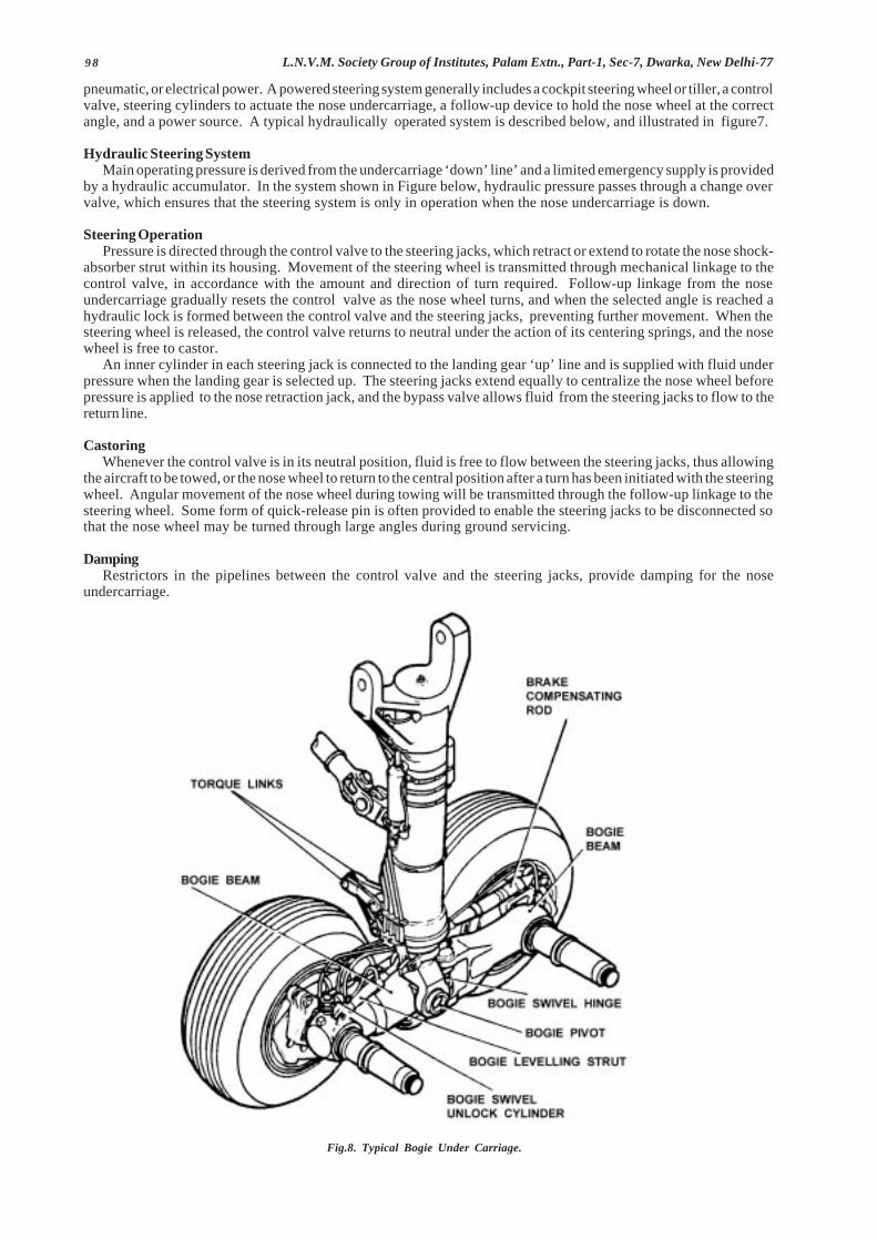
9 8 L.N.V.M. Society Group of Institutes, Palam Extn., Part-1, Sec-7, Dwarka, New Delhi-77
pneumatic, or electrical power. A powered steering system generally includes a cockpit steering wheel or tiller, a controlvalve, steering cylinders to actuate the nose undercarriage, a follow-up device to hold the nose wheel at the correctangle, and a power source. A typical hydraulically operated system is described below, and illustrated in figure7.
Hydraulic Steering SystemMain operating pressure is derived from the undercarriage ‘down’ line’ and a limited emergency supply is provided
by a hydraulic accumulator. In the system shown in Figure below, hydraulic pressure passes through a change overvalve, which ensures that the steering system is only in operation when the nose undercarriage is down.
Steering OperationPressure is directed through the control valve to the steering jacks, which retract or extend to rotate the nose shock-
absorber strut within its housing. Movement of the steering wheel is transmitted through mechanical linkage to thecontrol valve, in accordance with the amount and direction of turn required. Follow-up linkage from the noseundercarriage gradually resets the control valve as the nose wheel turns, and when the selected angle is reached ahydraulic lock is formed between the control valve and the steering jacks, preventing further movement. When thesteering wheel is released, the control valve returns to neutral under the action of its centering springs, and the nosewheel is free to castor.
An inner cylinder in each steering jack is connected to the landing gear ‘up’ line and is supplied with fluid underpressure when the landing gear is selected up. The steering jacks extend equally to centralize the nose wheel beforepressure is applied to the nose retraction jack, and the bypass valve allows fluid from the steering jacks to flow to thereturn line.
CastoringWhenever the control valve is in its neutral position, fluid is free to flow between the steering jacks, thus allowing
the aircraft to be towed, or the nose wheel to return to the central position after a turn has been initiated with the steeringwheel. Angular movement of the nose wheel during towing will be transmitted through the follow-up linkage to thesteering wheel. Some form of quick-release pin is often provided to enable the steering jacks to be disconnected sothat the nose wheel may be turned through large angles during ground servicing.
DampingRestrictors in the pipelines between the control valve and the steering jacks, provide damping for the nose
undercarriage.
Fig.8. Typical Bogie Under Carriage.

9 9Airframe and Aircraft Components
BOGIE UNDER CARRIAGESOn heavy aircraft, the need to spread the weight over a large area has resulted in the use of multiple wheel under
carriages. A typical four-wheeled bogie is illustrated in Fig. 8, but a larger number of wheels are used on some undercarriages.
The undercarriage unit normally consists of a shock-absorber strut, at the lower end of which a bogie beam is pivoted,and the axles are attached to each end of the beam. On some aircraft the rear pair of wheels swivels on the bogie beam,and castors when the nose wheel is turned through a large angle; on others, the upper torque link member is replacedby a pair of hydraulic jacks, which, when nose wheel steering is applied, rotates the whole bogie. Castoring or steeringprevents excessive torque on the undercarriage leg and minimizes tyre scrubbing during turns. For normal operation,the swivelling pair of wheels is locked in line with the fixed pair. Brake torque at each wheel is transmitted throughcompensating rods to the shock-absorber strut, thus preventing excessive loads on the bogie beam.
On retractable landing gear a levelling strut or ‘hop damper’ provides a means of positioning the bogie beam atsuitable angles for retraction and landing; this strut is usually connected into the hydraulic system to prevent retractionif the bogie is not at a suitable angle, and combines the functions of hydraulic ram and damper unit.
� � �
100 L.N.V.M. Society Group of Institutes, Palam Extn., Part-1, Sec-7, Dwarka, New Delhi-77
CHAPTER: 14TANKS
GENERALThere are three types of tanks in use; rigid or shell tanks, flexible tanks, and integral tanks (tanks which are formed
by sealing part of the structure). Rigid tanks are generally used for oil, de-icing fluid, hydraulic fluid, water, and, in somecases, fuel, whilst flexible and integral tanks are used almost exclusively for fuel, so as to make full use of the availablespace, and to save weight.
RIGID TANKSRigid tanks are normally used in engine oil systems, water systems, and the fuel systems of some light aircraft. Tanks
which are contained within the airframe structure are generally manufactured from aluminium alloy, and may be eitherriveted or welded. Some tanks, such as coolant header tanks, may be constructed from sheet brass or similar alloy,and others, which have to withstand high temperatures or corrosive fluids may be made from stainless steel. Externalfuel tanks are sometimes made from nonmetallic materials such as glass fibre.
InstallationRigid tanks are often mounted on suitably shaped bearers, and secured by means of padded metal straps, which
are joined and tightened by turn buckles. On some wing fuel tanks, however, the lower surface of the tank is also thewing skin, and is secured to the surrounding structure by screws. In instances where the tank skin or the tank bay closingpanel provides a load-bearing surface, the wing must be suitably supported before the tank is removed, and the supportsmust remain in position until the tank is re-installed and secured.
Before a tank is installed, the tank bay should be examined for cleanliness, damage and corrosion, and to ensure thatthere are no projections such as bolts, screws, or fasteners, which could chafe or damage the tank when it is in position.Any rectification necessary should be carried out, and protective treatment should be applied and allowed to dry. Thetank bay area should then be thoroughly cleaned, fuel pipe and vent connections should be prepared to receive thetank, and electrical power to any tank connections should be isolated. Blanks fitted to the pipes should be left in positionas long as possible, in order to prevent the ingress of foreign matter and moisture.
The tank which is to be fitted should be inspected for damage, all traces of inhibitor should be removed from it, andany components required for the tank, such as contents transmitters and booster pumps, should be installed inaccordance with the appropriate Maintenance Manual. Any filters should be inspected for cleanliness and securityand the filler cap, where fitted, should be checked for effective sealing. Vents should be checked to ensure they areproperly connected and unblocked. All fittings should be locked in the appropriate manner.
Care is necessary when installing a tank, since there is often very little clearance between the tank and tank bay,and access holes may permit only a limited view. Careless installation could result in damage to the tank, which maylead to subsequent leakage.
Connections should be made without bending or stretching the pipes, and, when required by the manufacturer,installation alignment tolerances should be checked . The introduction of a low point in a feed or vent pipe run couldresult in the collection of water at that point, which could lead to a blockage if the water freezes.
Straps should be tightened sufficiently to prevent the tank from moving, but over-tightening must be avoided. Itis important that all straps are tightened equally, to permit even distribution of strain.
Overboard drain and vent pipes should be checked after tank installation, to ensure they do not discharge in sucha manner that combustible fluids could leak into the structure or passenger compartments, and create a fire hazard.
The bonding of tanks which are not connected directly to the structure is most important, and all bonding stripsand cords should be securely attached. After installation of the tank, bonding should be checked.
The tank should then be filled, while the contents gauge is checked.
INSPECTIONInstalled tanks
All applicable panels in he aircraft skin adjacent to the tank should be removed, and the tank should be inspectedfor security correct adjustment of straps and slings, contamination, corrosion, superficial damage, cleanliness,distortion, and evidence of leakage form pipe connections, drains and the tanks itself. Leakage form connections mayoften be corrected in situ, by draining the tank and remaking the connection, but a damaged tank must, in most cases,be removed for repair.
Removed TanksTanks must be drained before being removed for inspection, and other associated tanks should be isolated by means
of their supply cocks, so that only the tank being removed is drained. Vent pipes must be clear, to prevent the tank fromcollapsing as the fuel drains out. When necessary the wing structure should be supported, access covers should beremoved, pipes and vents should be disconnected and blanked, and electrical services should be isolated anddisconnected. The tank should be released from its mountings, then carefully removed, and laid in a suitable cradle.The tank should then be thoroughly flushed and cleaned to remove all traces of fluid, sediment and gummy substances,
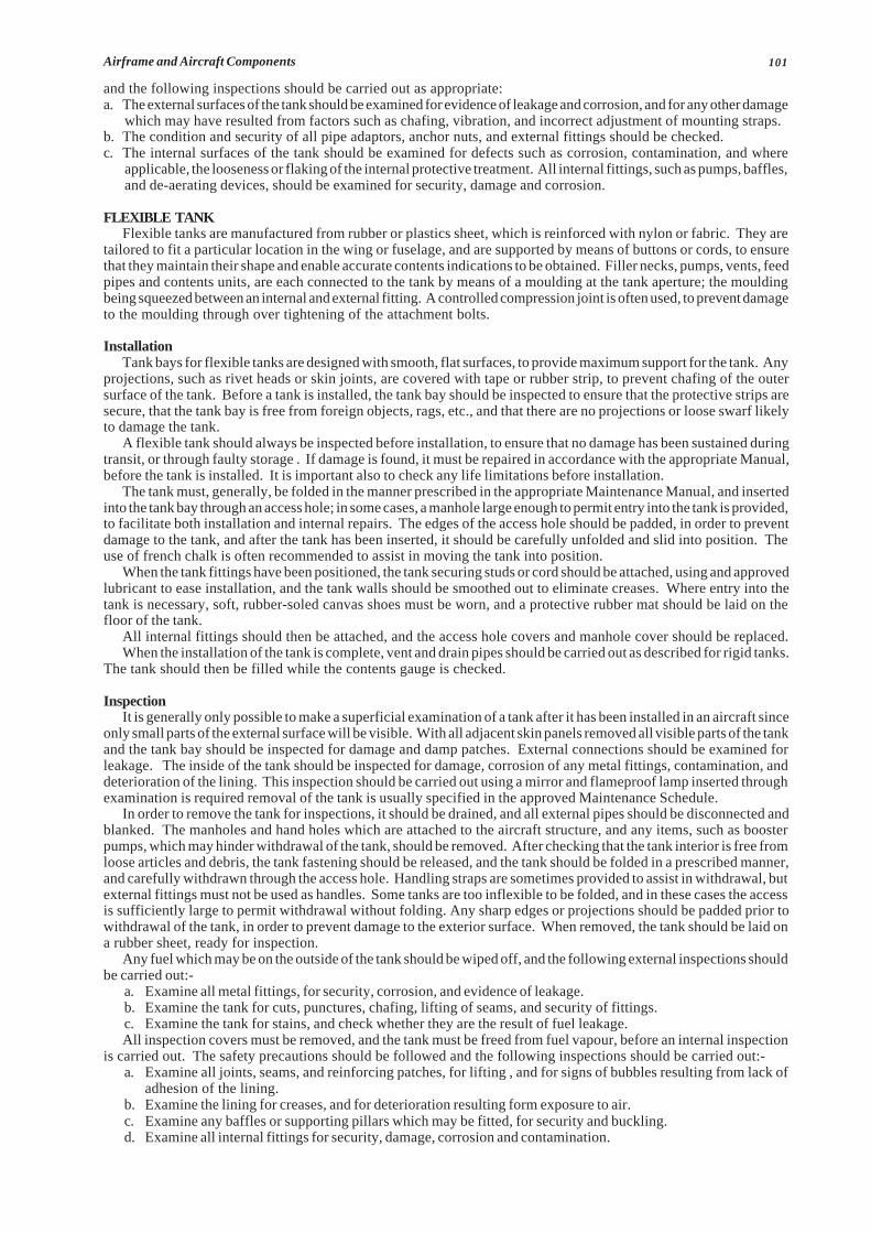
101Airframe and Aircraft Components
and the following inspections should be carried out as appropriate:a. The external surfaces of the tank should be examined for evidence of leakage and corrosion, and for any other damage
which may have resulted from factors such as chafing, vibration, and incorrect adjustment of mounting straps.b. The condition and security of all pipe adaptors, anchor nuts, and external fittings should be checked.c. The internal surfaces of the tank should be examined for defects such as corrosion, contamination, and where
applicable, the looseness or flaking of the internal protective treatment. All internal fittings, such as pumps, baffles,and de-aerating devices, should be examined for security, damage and corrosion.
FLEXIBLE TANKFlexible tanks are manufactured from rubber or plastics sheet, which is reinforced with nylon or fabric. They are
tailored to fit a particular location in the wing or fuselage, and are supported by means of buttons or cords, to ensurethat they maintain their shape and enable accurate contents indications to be obtained. Filler necks, pumps, vents, feedpipes and contents units, are each connected to the tank by means of a moulding at the tank aperture; the mouldingbeing squeezed between an internal and external fitting. A controlled compression joint is often used, to prevent damageto the moulding through over tightening of the attachment bolts.
InstallationTank bays for flexible tanks are designed with smooth, flat surfaces, to provide maximum support for the tank. Any
projections, such as rivet heads or skin joints, are covered with tape or rubber strip, to prevent chafing of the outersurface of the tank. Before a tank is installed, the tank bay should be inspected to ensure that the protective strips aresecure, that the tank bay is free from foreign objects, rags, etc., and that there are no projections or loose swarf likelyto damage the tank.
A flexible tank should always be inspected before installation, to ensure that no damage has been sustained duringtransit, or through faulty storage . If damage is found, it must be repaired in accordance with the appropriate Manual,before the tank is installed. It is important also to check any life limitations before installation.
The tank must, generally, be folded in the manner prescribed in the appropriate Maintenance Manual, and insertedinto the tank bay through an access hole; in some cases, a manhole large enough to permit entry into the tank is provided,to facilitate both installation and internal repairs. The edges of the access hole should be padded, in order to preventdamage to the tank, and after the tank has been inserted, it should be carefully unfolded and slid into position. Theuse of french chalk is often recommended to assist in moving the tank into position.
When the tank fittings have been positioned, the tank securing studs or cord should be attached, using and approvedlubricant to ease installation, and the tank walls should be smoothed out to eliminate creases. Where entry into thetank is necessary, soft, rubber-soled canvas shoes must be worn, and a protective rubber mat should be laid on thefloor of the tank.
All internal fittings should then be attached, and the access hole covers and manhole cover should be replaced.When the installation of the tank is complete, vent and drain pipes should be carried out as described for rigid tanks.
The tank should then be filled while the contents gauge is checked.
InspectionIt is generally only possible to make a superficial examination of a tank after it has been installed in an aircraft since
only small parts of the external surface will be visible. With all adjacent skin panels removed all visible parts of the tankand the tank bay should be inspected for damage and damp patches. External connections should be examined forleakage. The inside of the tank should be inspected for damage, corrosion of any metal fittings, contamination, anddeterioration of the lining. This inspection should be carried out using a mirror and flameproof lamp inserted throughexamination is required removal of the tank is usually specified in the approved Maintenance Schedule.
In order to remove the tank for inspections, it should be drained, and all external pipes should be disconnected andblanked. The manholes and hand holes which are attached to the aircraft structure, and any items, such as boosterpumps, which may hinder withdrawal of the tank, should be removed. After checking that the tank interior is free fromloose articles and debris, the tank fastening should be released, and the tank should be folded in a prescribed manner,and carefully withdrawn through the access hole. Handling straps are sometimes provided to assist in withdrawal, butexternal fittings must not be used as handles. Some tanks are too inflexible to be folded, and in these cases the accessis sufficiently large to permit withdrawal without folding. Any sharp edges or projections should be padded prior towithdrawal of the tank, in order to prevent damage to the exterior surface. When removed, the tank should be laid ona rubber sheet, ready for inspection.
Any fuel which may be on the outside of the tank should be wiped off, and the following external inspections shouldbe carried out:-
a. Examine all metal fittings, for security, corrosion, and evidence of leakage.b. Examine the tank for cuts, punctures, chafing, lifting of seams, and security of fittings.c. Examine the tank for stains, and check whether they are the result of fuel leakage.All inspection covers must be removed, and the tank must be freed from fuel vapour, before an internal inspection
is carried out. The safety precautions should be followed and the following inspections should be carried out:-a. Examine all joints, seams, and reinforcing patches, for lifting , and for signs of bubbles resulting from lack of
adhesion of the lining.b. Examine the lining for creases, and for deterioration resulting form exposure to air.c. Examine any baffles or supporting pillars which may be fitted, for security and buckling.d. Examine all internal fittings for security, damage, corrosion and contamination.
102 L.N.V.M. Society Group of Institutes, Palam Extn., Part-1, Sec-7, Dwarka, New Delhi-77
Any damage, lack of adhesion, or bubbles, which are likely to result in leakage, should be repaired, and a pressuretest should be carried out before the tank is returned to service.
INTEGRAL TANKSIntegral tanks are often formed by sealing the whole of the wing torque box during manufacture. Chordal diaphragms
both divide the wing into a number of compartments, or tanks, and also prevent surge; external or internal pipes connectthe tanks into the fuel system. A number of methods are used for sealing the structure, including the use of sealantas a flaying compound between mating surfaces, and the use of a filleting compound at the edges. The interior of thetank is then further protected by tank coatings, which may be applied by slushing, brushing or spraying. Any or allof these methods may be used on a particular aircraft, and may be accompanied by special paint schemes, which aredesigned to minimise microbiological attack. A suitable number of large access panels, hand holes, and tankconnections, are included in the structure at strategic positions; the covers are normally made fuel tight by using sealsor sealant at the mating surfaces.
In some cases, corrosion inhibitor cartridges are fitted in integral tanks. Typically, these cartridges consist ofstrontium chromate or calcium chromate tablets contained in a linen bag. It is a requirement with such cartridges thatthe linen bag should be thoroughly wetted with water before installation, and after tank repair operations.
InspectionAt the periods specified in the approved Maintenance Schedule, the fuel tanks should be inspected for leaks,
corrosion or damage to internal components, freedom of operation of non return and anti-surge valves, andmicrobiological contamination. Particular attention should be paid to areas of stress concentration, and holes whichhave been formed in the spar webs or structure for the purpose of mounting booster pumps or other heavy components,to ensure that no cracks have developed.
To check for leakage, the tanks should be filled to maximum capacity, and a whitening solution (e.g. dye penetrantdeveloper) should be applied over all joints, rivets, and bolts, which may be likely sources of leaks. After a soakingperiod (4 to 12 hours), the external surfaces should be inspected for drips, and for any staining of the developer. If leaksare found they should be marked with a soft crayon, and should subsequently be categorized and repaired, as necessary.The developer should be removed with a soft bristle brush, and the tank should be washed off.
Microbiological contamination is more easily visible when it is wet, and, when access is provided in the top skin,the tanks need only be drained sufficiently to permit removal of a suitable hand hole cover. The interior surfaces whichare visible through the handhole, should be inspected, using a flame- proof torch, for signs of brown, slimy deposits.This inspection should be carried out, initially, on the tanks which have been found by experience to be the most critical(usually the inboard wing tanks), but, if contamination is found, the remaining tanks must be checked. Anycontamination must be removed.
An examination for corrosion of internal metallic parts is best carried out when the tanks are empty, so that entryinto the tanks may be effected. The safety precautions must be observed, and particular care must be taken not to damagethe tank sealant. In some large aircraft the tanks must be drained in a prescribed order, or the aircraft must be jackedwhen individual tanks are drained.
PRESSURE TESTSAfter repairs have been carried out on rigid and flexible tanks, a pressure test is usually specified to ensure that the
leaks have been cured. Pressure testing of integral tanks is not normally required, but flow tests may be specified.In order to apply pressure to a tank, leak proof blanks must be fitted to all apertures, and one blank must include
a fitting suitable for the attachment of a dry air supply. A pressure gauge (normally a water manometer) should be fittedin the pressure line.
Rigid tanks may be pressure tested by filling with a few gallons or kerosene, and applying an mixture of whiting andmethylated spirit to all seams, joints and other possible sources of leaks. When the mixture has dried, an air pressureof approximately 10 kN/m2 (1.5 1bf/in2) is applied to the inside of the tank, which is then rotated to distribute keroseneover the whole surface. Leaks will be indicated by staining of the whiting. After the test, the whiting should be washedoff, the kerosene should be drained, and the tank, if not required for kerosene, should be flushed with the appropriatesystem fluid. As an alternative, the test described below, using dry air pressure and soap solution, may be used.
Flexible tanks may be pressure-tested in a number of ways: by the free test method, by the use of pressure rigs, orby a chemical method.
The free test method is similar to the test used for rigid tanks. The tank is filled with a few gallons of kerosene, andan air pressure of not more than 2kN/m2(0.25 1bf/in2) is applied in order to shape out the tank. The tank is then rotatedin order to distribute the kerosene, and any leaks will be indicated by the presence of kerosene on the exterior surfaces.
The pressure rig method is carried out with the tank contained within a frame, which is designed to support the tank.The frame consists of a welded steel structure inlaid with a wide mesh screen, which permits inspection of all seamsand fittings; each frame is designed for use with a particular tank. The tank is carefully located in the frame, and an airpressure of approximately 7 kN/m2 (1 lbf/in2) is applied to the tank. A soap solution is brushed over the tank skin, andif a leak is present, it will be indicated by the appearance of bubbles. After the test, the soap solution should be washedoff, the tank should be drained, and, where necessary, the tank should be flushed with system fluid.
In the chemical method, a rag soaked in ammonia is inserted into the tank, which is then sealed and inflated to apressure of 4kN/m2(0.5 lbf/cm2). A large cloth is then soaked in an indicator solution containing 2.25 litres (0.5 gal) ofwater, 2.25 litres (0.5 gal) of ethyl alcohol and 40g of phenolhralein crytals, wrung out, and spread over an area of thetank to be checked. Leaks will be indicated by the appearance of red spots on the cloth, and should be marked on the
103Airframe and Aircraft Components
tank with a silver coloured pencil. The cloth should again be soaked in the indicator solution, and wrung out beforechecking a different area on the tank.
SAFETY PRECAUTIONSWhenever it is necessary to enter a tank, in order to make an inspection, or to carry out repairs, certain precautions
must be taken because of the flammability and toxicity of fuel and oil vapours. Defuelling and ventilating operationsmust be carried out in an open area, and no flame or spark producing equipment may be operated in the vicinity of suchoperations, or when fuel tank covers are open. Adequate and properly manned fire - fighting equipment must beprovided, and suitable placards should be prominently displayed. The aircraft, and any ground equipment used, shouldbe electrically earthed to a satisfactory earthing point.
After a tank has been defuelled and drained, it must be ventilated, by removing all access covers and circulatingdry, filtered air, through the tank, until all fumes have been removed. The period of ventilation will very according toambient conditions, but must be continued until the tank walls are completely dry. Interconnecting feed and vent pipesmust be blanked or isolated, in order to prevent any liquid or vapour in adjacent tanks, from contaminating the purgedtank.
Battery cables should be removed and stowed, to prevent inadvertent sparking of electrical tank units.Only spark-proof tools and explosion-proof torches may be taken into the tank, and only air-operated vacuum
cleaners may be used for removing debris.All tools required for a particular operation, should be cleaned and placed in a shallow open-topped box, so as to
limit the movement of personnel through the access hole, and to minimize the possibility of the tank becomingcontaminated with dirt and grit. A check list should be kept of all tools and equipment taken into the tank, and itemsshould be checked off this list as they are removed, before the final inspection of the interior and the replacement ofthe tank covers.
The edges of holes through which entry is to be made, and the edges of passage ways in internal formers, must beprotected from damage, and protective mats must be placed on the bottom of the tank.
Personnel working in a tank must wear an air-fed respirator, and a supply of fresh air should be circulated throughthe tank. Protective clothing should be worn, and this should include canvas shoes, clean cotton overalls (which shouldbe free from exposed metal buttons, buckles or fasteners), and clean cotton head covering. Goggles and rubber glovesshould also be worn when solvents and sealants are to be sealants are to be handled.
Particular care must be taken when working inside water/methanol tanks, since methanol may be absorbed throughthe skin. For such work the protective clothing should cover the whole body.
A lifeline should be attached to a person who is working inside the tank, and a second person should be stationedoutside the tank, to maintain contact with, and to be responsible for, the safety of the first person. Where there is analternative access hole this should be opened, in case the person inside the tank should require assistance.
� � �
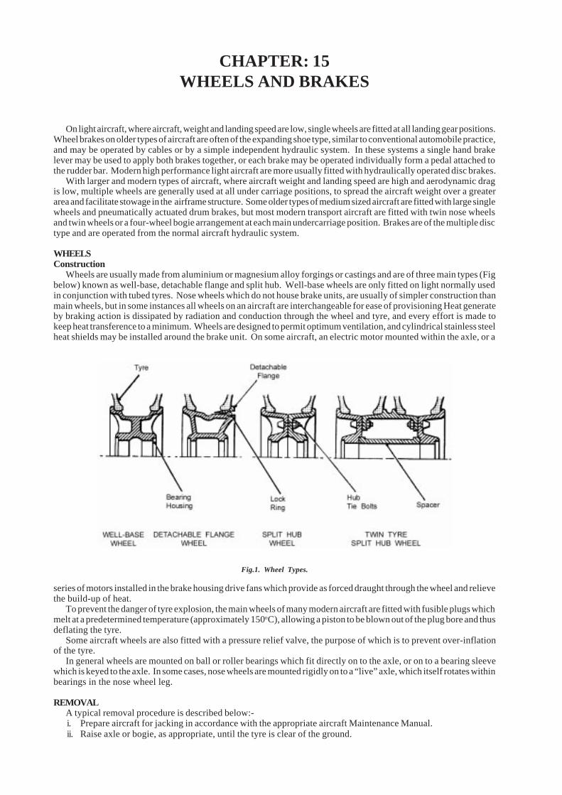
104 L.N.V.M. Society Group of Institutes, Palam Extn., Part-1, Sec-7, Dwarka, New Delhi-77
CHAPTER: 15WHEELS AND BRAKES
On light aircraft, where aircraft, weight and landing speed are low, single wheels are fitted at all landing gear positions.Wheel brakes on older types of aircraft are often of the expanding shoe type, similar to conventional automobile practice,and may be operated by cables or by a simple independent hydraulic system. In these systems a single hand brakelever may be used to apply both brakes together, or each brake may be operated individually form a pedal attached tothe rudder bar. Modern high performance light aircraft are more usually fitted with hydraulically operated disc brakes.
With larger and modern types of aircraft, where aircraft weight and landing speed are high and aerodynamic dragis low, multiple wheels are generally used at all under carriage positions, to spread the aircraft weight over a greaterarea and facilitate stowage in the airframe structure. Some older types of medium sized aircraft are fitted with large singlewheels and pneumatically actuated drum brakes, but most modern transport aircraft are fitted with twin nose wheelsand twin wheels or a four-wheel bogie arrangement at each main undercarriage position. Brakes are of the multiple disctype and are operated from the normal aircraft hydraulic system.
WHEELSConstruction
Wheels are usually made from aluminium or magnesium alloy forgings or castings and are of three main types (Figbelow) known as well-base, detachable flange and split hub. Well-base wheels are only fitted on light normally usedin conjunction with tubed tyres. Nose wheels which do not house brake units, are usually of simpler construction thanmain wheels, but in some instances all wheels on an aircraft are interchangeable for ease of provisioning Heat generateby braking action is dissipated by radiation and conduction through the wheel and tyre, and every effort is made tokeep heat transference to a minimum. Wheels are designed to permit optimum ventilation, and cylindrical stainless steelheat shields may be installed around the brake unit. On some aircraft, an electric motor mounted within the axle, or a
Fig.1. Wheel Types.
series of motors installed in the brake housing drive fans which provide as forced draught through the wheel and relievethe build-up of heat.
To prevent the danger of tyre explosion, the main wheels of many modern aircraft are fitted with fusible plugs whichmelt at a predetermined temperature (approximately 150oC), allowing a piston to be blown out of the plug bore and thusdeflating the tyre.
Some aircraft wheels are also fitted with a pressure relief valve, the purpose of which is to prevent over-inflationof the tyre.
In general wheels are mounted on ball or roller bearings which fit directly on to the axle, or on to a bearing sleevewhich is keyed to the axle. In some cases, nose wheels are mounted rigidly on to a “live” axle, which itself rotates withinbearings in the nose wheel leg.
REMOVALA typical removal procedure is described below:-i. Prepare aircraft for jacking in accordance with the appropriate aircraft Maintenance Manual.ii. Raise axle or bogie, as appropriate, until the tyre is clear of the ground.
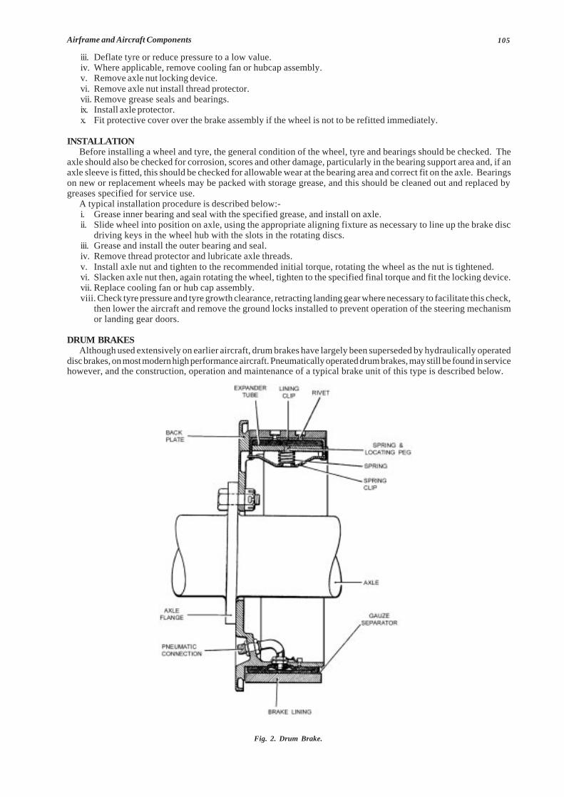
105Airframe and Aircraft Components
iii. Deflate tyre or reduce pressure to a low value.iv. Where applicable, remove cooling fan or hubcap assembly.v. Remove axle nut locking device.vi. Remove axle nut install thread protector.vii. Remove grease seals and bearings.ix. Install axle protector.x. Fit protective cover over the brake assembly if the wheel is not to be refitted immediately.
INSTALLATIONBefore installing a wheel and tyre, the general condition of the wheel, tyre and bearings should be checked. The
axle should also be checked for corrosion, scores and other damage, particularly in the bearing support area and, if anaxle sleeve is fitted, this should be checked for allowable wear at the bearing area and correct fit on the axle. Bearingson new or replacement wheels may be packed with storage grease, and this should be cleaned out and replaced bygreases specified for service use.
A typical installation procedure is described below:-i. Grease inner bearing and seal with the specified grease, and install on axle.ii. Slide wheel into position on axle, using the appropriate aligning fixture as necessary to line up the brake disc
driving keys in the wheel hub with the slots in the rotating discs.iii. Grease and install the outer bearing and seal.iv. Remove thread protector and lubricate axle threads.v. Install axle nut and tighten to the recommended initial torque, rotating the wheel as the nut is tightened.vi. Slacken axle nut then, again rotating the wheel, tighten to the specified final torque and fit the locking device.vii. Replace cooling fan or hub cap assembly.viii. Check tyre pressure and tyre growth clearance, retracting landing gear where necessary to facilitate this check,
then lower the aircraft and remove the ground locks installed to prevent operation of the steering mechanismor landing gear doors.
DRUM BRAKESAlthough used extensively on earlier aircraft, drum brakes have largely been superseded by hydraulically operated
disc brakes, on most modern high performance aircraft. Pneumatically operated drum brakes, may still be found in servicehowever, and the construction, operation and maintenance of a typical brake unit of this type is described below.
Fig. 2. Drum Brake.
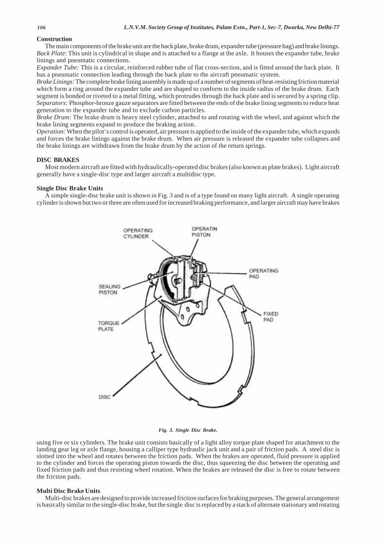
106 L.N.V.M. Society Group of Institutes, Palam Extn., Part-1, Sec-7, Dwarka, New Delhi-77
ConstructionThe main components of the brake unit are the back plate, brake drum, expander tube (pressure bag) and brake linings.
Back Plate: This unit is cylindrical in shape and is attached to a flange at the axle. It houses the expander tube, brakelinings and pneumatic connections.Expander Tube: This is a circular, reinforced rubber tube of flat cross-section, and is fitted around the back plate. Ithas a pneumatic connection leading through the back plate to the aircraft pneumatic system.Brake Linings: The complete brake lining assembly is made up of a number of segments of heat-resisting friction materialwhich form a ring around the expander tube and are shaped to conform to the inside radius of the brake drum. Eachsegment is bonded or riveted to a metal fitting, which protrudes through the back plate and is secured by a spring clip.Separators: Phosphor-bronze gauze separators are fitted between the ends of the brake lining segments to reduce heatgeneration to the expander tube and to exclude carbon particles.Brake Drum: The brake drum is heavy steel cylinder, attached to and rotating with the wheel, and against which thebrake lining segments expand to produce the braking action.Operation: When the pilot’s control is operated, air pressure is applied to the inside of the expander tube, which expandsand forces the brake linings against the brake drum. When air pressure is released the expander tube collapses andthe brake linings are withdrawn from the brake drum by the action of the return springs.
DISC BRAKESMost modern aircraft are fitted with hydraulically-operated disc brakes (also known as plate brakes). Light aircraft
generally have a single-disc type and larger aircraft a multidisc type.
Single Disc Brake UnitsA simple single-disc brake unit is shown in Fig. 3 and is of a type found on many light aircraft. A single operating
cylinder is shown but two or three are often used for increased braking performance, and larger aircraft may have brakes
Fig. 3. Single Disc Brake.
using five or six cylinders. The brake unit consists basically of a light alloy torque plate shaped for attachment to thelanding gear leg or axle flange, housing a calliper type hydraulic jack unit and a pair of friction pads. A steel disc isslotted into the wheel and rotates between the friction pads. When the brakes are operated, fluid pressure is appliedto the cylinder and forces the operating piston towards the disc, thus squeezing the disc between the operating andfixed friction pads and thus resisting wheel rotation. When the brakes are released the disc is free to rotate betweenthe friction pads.
Multi Disc Brake UnitsMulti-disc brakes are designed to provide increased friction surfaces for braking purposes. The general arrangement
is basically similar to the single-disc brake, but the single disc is replaced by a stack of alternate stationary and rotating

107Airframe and Aircraft Components
discs, and a number of operating cylinders are equally spaced around the torque rotating discs, and a number ofoperating cylinders are equally spaced around the torque plate. The friction elements are normally in the form of padsattached to either side of the stationary discs, but on some types the rotating discs have sintered surfaces or pads.This type of brake is operated from the aircraft’s main hydraulic system, through valves connected to the pilot’s rudderpedals.
ConstructionA typical multi-disc brake unit is shown in Fig. 4. In this unit a torque plate and torque tube assembly fits over the
axle and is bolted to a flange on the axle; alternative designs are often similarly mounted but prevented form rotating
Fig.4. Multi Disc Brake.
by means of a torque arm attached to a suitable fixture on the landing gear leg or bogie. A number or cylinders are spacedaround the torque plate, connected to the hydraulic brake system and house a piston which apply load to the pressureplate. The disc pack (also known as the heat pack) contains alternate stationary and rotating discs, the stationary discsbeing keyed to the torque tube and the rotating discs house the brake pads and the rotating discs are segmented toprevent heat distortion and brake drag. Correct working clearance in the disc pack is maintained by means of adjusterassemblies. Pins attached to the pressure plate and protruding through the torque plate on this brake unit, indicate theamount of wear which has taken place in the disc pack.
A further type of multi-disc brake is known as a trimetallic brake. Construction is similar to the brake described above,except that the rotating discs have as metallic compound sintered to their faces, and steel segments, known as wearpads, are riveted to the faces of the stationary discs. Alternatively, the faces of both sets of discs may be sintered,or the stationary discs may be plain.
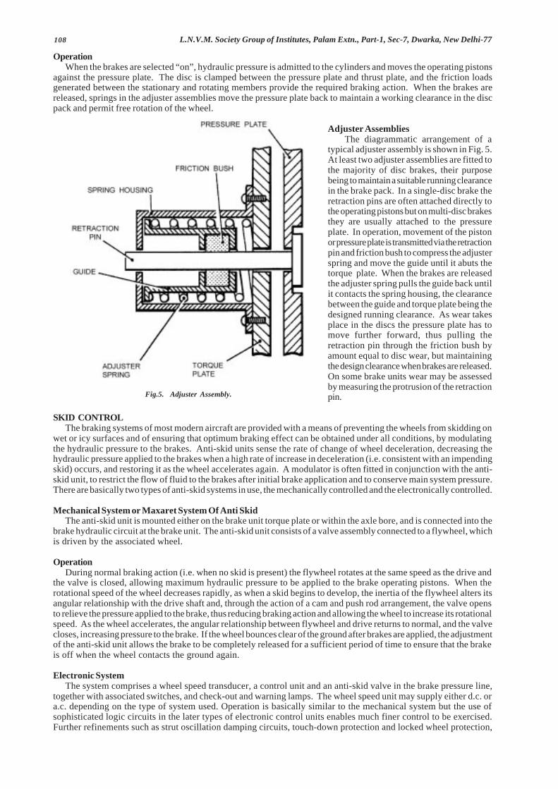
108 L.N.V.M. Society Group of Institutes, Palam Extn., Part-1, Sec-7, Dwarka, New Delhi-77
OperationWhen the brakes are selected “on”, hydraulic pressure is admitted to the cylinders and moves the operating pistons
against the pressure plate. The disc is clamped between the pressure plate and thrust plate, and the friction loadsgenerated between the stationary and rotating members provide the required braking action. When the brakes arereleased, springs in the adjuster assemblies move the pressure plate back to maintain a working clearance in the discpack and permit free rotation of the wheel.
Adjuster AssembliesThe diagrammatic arrangement of a
typical adjuster assembly is shown in Fig. 5.At least two adjuster assemblies are fitted tothe majority of disc brakes, their purposebeing to maintain a suitable running clearancein the brake pack. In a single-disc brake theretraction pins are often attached directly tothe operating pistons but on multi-disc brakesthey are usually attached to the pressureplate. In operation, movement of the pistonor pressure plate is transmitted via the retractionpin and friction bush to compress the adjusterspring and move the guide until it abuts thetorque plate. When the brakes are releasedthe adjuster spring pulls the guide back untilit contacts the spring housing, the clearancebetween the guide and torque plate being thedesigned running clearance. As wear takesplace in the discs the pressure plate has tomove further forward, thus pulling theretraction pin through the friction bush byamount equal to disc wear, but maintainingthe design clearance when brakes are released.On some brake units wear may be assessedby measuring the protrusion of the retractionpin.
SKID CONTROLThe braking systems of most modern aircraft are provided with a means of preventing the wheels from skidding on
wet or icy surfaces and of ensuring that optimum braking effect can be obtained under all conditions, by modulatingthe hydraulic pressure to the brakes. Anti-skid units sense the rate of change of wheel deceleration, decreasing thehydraulic pressure applied to the brakes when a high rate of increase in deceleration (i.e. consistent with an impendingskid) occurs, and restoring it as the wheel accelerates again. A modulator is often fitted in conjunction with the anti-skid unit, to restrict the flow of fluid to the brakes after initial brake application and to conserve main system pressure.There are basically two types of anti-skid systems in use, the mechanically controlled and the electronically controlled.
Mechanical System or Maxaret System Of Anti SkidThe anti-skid unit is mounted either on the brake unit torque plate or within the axle bore, and is connected into the
brake hydraulic circuit at the brake unit. The anti-skid unit consists of a valve assembly connected to a flywheel, whichis driven by the associated wheel.
OperationDuring normal braking action (i.e. when no skid is present) the flywheel rotates at the same speed as the drive and
the valve is closed, allowing maximum hydraulic pressure to be applied to the brake operating pistons. When therotational speed of the wheel decreases rapidly, as when a skid begins to develop, the inertia of the flywheel alters itsangular relationship with the drive shaft and, through the action of a cam and push rod arrangement, the valve opensto relieve the pressure applied to the brake, thus reducing braking action and allowing the wheel to increase its rotationalspeed. As the wheel accelerates, the angular relationship between flywheel and drive returns to normal, and the valvecloses, increasing pressure to the brake. If the wheel bounces clear of the ground after brakes are applied, the adjustmentof the anti-skid unit allows the brake to be completely released for a sufficient period of time to ensure that the brakeis off when the wheel contacts the ground again.
Electronic SystemThe system comprises a wheel speed transducer, a control unit and an anti-skid valve in the brake pressure line,
together with associated switches, and check-out and warning lamps. The wheel speed unit may supply either d.c. ora.c. depending on the type of system used. Operation is basically similar to the mechanical system but the use ofsophisticated logic circuits in the later types of electronic control units enables much finer control to be exercised.Further refinements such as strut oscillation damping circuits, touch-down protection and locked wheel protection,
Fig.5. Adjuster Assembly.
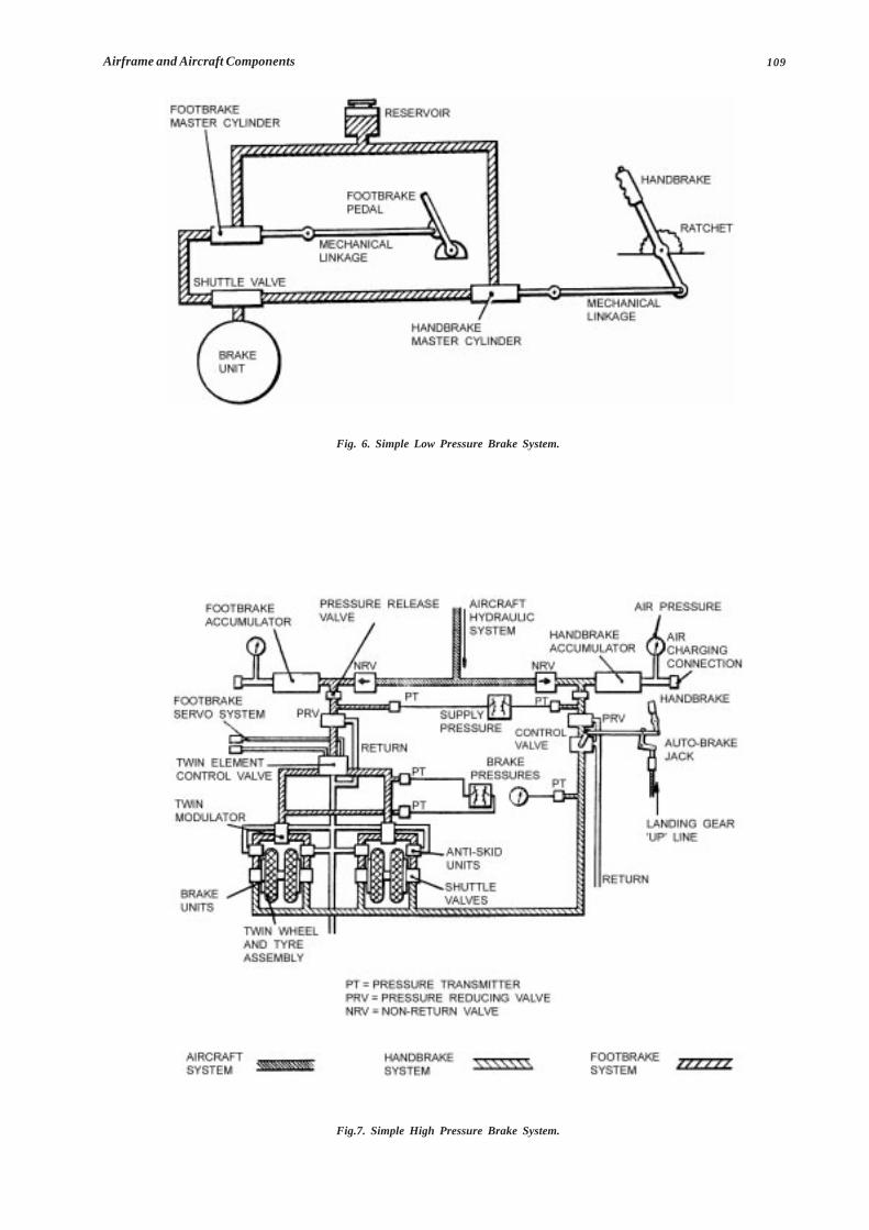
109Airframe and Aircraft Components
Fig. 6. Simple Low Pressure Brake System.
Fig.7. Simple High Pressure Brake System.
110 L.N.V.M. Society Group of Institutes, Palam Extn., Part-1, Sec-7, Dwarka, New Delhi-77
may also be incorporated and some systems automatically de-activate at low speed to prevent interference with normaltaxying manoeuvres.
The method by which the wheel speed signal is processed in the control unit varies form type to type, but all operateon the basis that if any brake produces more torque than can be supported by the friction between the tyre and groundfor the existing wheel load, the resulting impending skid will produce a smaller rotational velocity signal from the affectedwheel. This reduced signal is detected by the anti-skid control circuits, which send a signal to the anti-skid controlvalve, causing brake pressure to be reduced sufficiently to correct the skid condition. Brake pressure will be re-appliedto a level just below that which caused the skid, and will then increase at a controlled rate.
Control units normally circuits which provide warning of failure in the system, and a self-test facility which enablesthe serviceability of the various components to be checked. Controls for the operation and testing of the anti-skidsystem are contained in the control unit and in the flight compartment.
Some systems operate by providing a continuous bleed from the brake pressure line, and in these cases the parkingbrake operates a cut-off valve in the brake return line.
LOW PRESSURE BRAKE SYSTEMSMost light aircraft are fitted with an independent hydraulic system for each brake, similar to that shown in fig. 6. On
some aircraft a handbrake system is connected to each brake through a shuttle valve, while on others a parking brakecontrol applies a mechanical lock to the foot brake linkage when brakes are applied. The main components in each systemare a fluid reservoir and master cylinder, connected mechanically to the brake pedals and hydraulically to the brakeoperating cylinder.
OperationAs the brake pedal is pressed, a piston in the master cylinder forces fluid through the pipelines to the brake operating
cylinder, the braking force depending on the force exerted on the brake pedal. When the pedal is released, a return springin the master cylinder returns the piston to its original position, and pressure is relieved. Handbrake operation is similarexcept that the shuttle valve moves to allow pressure to the brake unit and close off the port from the foot brake mastercylinder; brakes are held on by a ratchet device in the handbrake mounting. With the alternative parking brake system,the brake should be set by applying pressure with the foot brake, then the parking brake operated to lock the foot brakelinkage; subsequent foot brake application will release the locking catch.
HIGH PRESSURE BRAKE SYSTEMSHigh pressure braking systems use the normal aircraft hydraulic system to provide fluid, under pressure, to the brake
units. A brake system accumulator stores energy in the brake system for use in the event of normal system pressurenot being available, and an emergency pneumatic system is frequently included to safe guard brake operation in theevent of complete hydraulic failure. A simplified system is shown in fig 7.
Operation of the brakes can be controlled from either pilot’s position by brake pedals attached to the rudder bar.Application of operation of the associated left or right brakes.
The brake pedals are linked through a system of levers and cables, or a hydraulic servo system, to a control valve(normally located adjacent to the main wheel bays to minimise the length of pipe run) which controls hydraulic pressureaccording to the position of the brake pedals. This pressure is often reduced through a pressure reducing valve, andmodulated by an anti-skid valve, before being applied to the brake cylinders.
AdjustmentThe accurate setting-up of the mechanical linkage between the rudder pedals and control valve is very important
since it controls the brake pressure in relation to pedal movement and must be identical in both left and right brakingsystems. Details of the setting-up procedures for a particular aircraft system will be found in the approved maintenancemanual, but in a normal system, levers and bell cranks are locked in position by the insertion of rigging pins and theconnecting rods and cables adjusted to fit these fixed locations. Alternatively, graduated quadrants may be fitted toshow the angular positions of particular levers so that the connecting components may be correctly adjusted. Cablesshould be tightened to the tension quoted in the Maintenance manual.
� � �
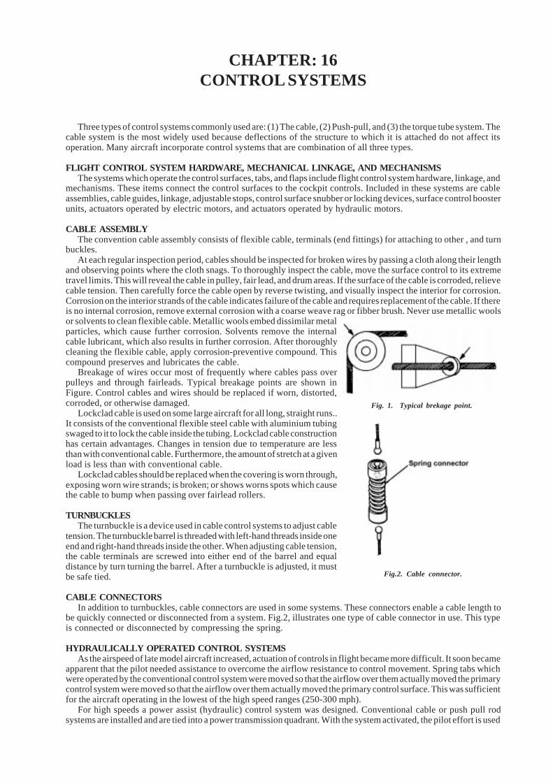
111Airframe and Aircraft Components
CHAPTER: 16CONTROL SYSTEMS
Three types of control systems commonly used are: (1) The cable, (2) Push-pull, and (3) the torque tube system. Thecable system is the most widely used because deflections of the structure to which it is attached do not affect itsoperation. Many aircraft incorporate control systems that are combination of all three types.
FLIGHT CONTROL SYSTEM HARDWARE, MECHANICAL LINKAGE, AND MECHANISMSThe systems which operate the control surfaces, tabs, and flaps include flight control system hardware, linkage, and
mechanisms. These items connect the control surfaces to the cockpit controls. Included in these systems are cableassemblies, cable guides, linkage, adjustable stops, control surface snubber or locking devices, surface control boosterunits, actuators operated by electric motors, and actuators operated by hydraulic motors.
CABLE ASSEMBLYThe convention cable assembly consists of flexible cable, terminals (end fittings) for attaching to other , and turn
buckles.At each regular inspection period, cables should be inspected for broken wires by passing a cloth along their length
and observing points where the cloth snags. To thoroughly inspect the cable, move the surface control to its extremetravel limits. This will reveal the cable in pulley, fair lead, and drum areas. If the surface of the cable is corroded, relievecable tension. Then carefully force the cable open by reverse twisting, and visually inspect the interior for corrosion.Corrosion on the interior strands of the cable indicates failure of the cable and requires replacement of the cable. If thereis no internal corrosion, remove external corrosion with a coarse weave rag or fibber brush. Never use metallic woolsor solvents to clean flexible cable. Metallic wools embed dissimilar metalparticles, which cause further corrosion. Solvents remove the internalcable lubricant, which also results in further corrosion. After thoroughlycleaning the flexible cable, apply corrosion-preventive compound. Thiscompound preserves and lubricates the cable.
Breakage of wires occur most of frequently where cables pass overpulleys and through fairleads. Typical breakage points are shown inFigure. Control cables and wires should be replaced if worn, distorted,corroded, or otherwise damaged.
Lockclad cable is used on some large aircraft for all long, straight runs..It consists of the conventional flexible steel cable with aluminium tubingswaged to it to lock the cable inside the tubing. Lockclad cable constructionhas certain advantages. Changes in tension due to temperature are lessthan with conventional cable. Furthermore, the amount of stretch at a givenload is less than with conventional cable.
Lockclad cables should be replaced when the covering is worn through,exposing worn wire strands; is broken; or shows worns spots which causethe cable to bump when passing over fairlead rollers.
TURNBUCKLESThe turnbuckle is a device used in cable control systems to adjust cable
tension. The turnbuckle barrel is threaded with left-hand threads inside oneend and right-hand threads inside the other. When adjusting cable tension,the cable terminals are screwed into either end of the barrel and equaldistance by turn turning the barrel. After a turnbuckle is adjusted, it mustbe safe tied.
CABLE CONNECTORSIn addition to turnbuckles, cable connectors are used in some systems. These connectors enable a cable length to
be quickly connected or disconnected from a system. Fig.2, illustrates one type of cable connector in use. This typeis connected or disconnected by compressing the spring.
HYDRAULICALLY OPERATED CONTROL SYSTEMSAs the airspeed of late model aircraft increased, actuation of controls in flight became more difficult. It soon became
apparent that the pilot needed assistance to overcome the airflow resistance to control movement. Spring tabs whichwere operated by the conventional control system were moved so that the airflow over them actually moved the primarycontrol system were moved so that the airflow over them actually moved the primary control surface. This was sufficientfor the aircraft operating in the lowest of the high speed ranges (250-300 mph).
For high speeds a power assist (hydraulic) control system was designed. Conventional cable or push pull rodsystems are installed and are tied into a power transmission quadrant. With the system activated, the pilot effort is used
Fig. 1. Typical brekage point.
Fig.2. Cable connector.
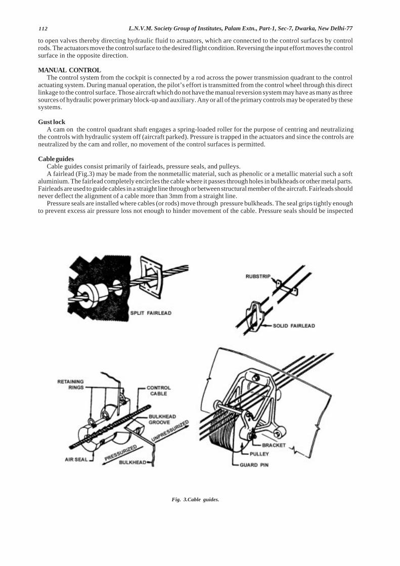
112 L.N.V.M. Society Group of Institutes, Palam Extn., Part-1, Sec-7, Dwarka, New Delhi-77
to open valves thereby directing hydraulic fluid to actuators, which are connected to the control surfaces by controlrods. The actuators move the control surface to the desired flight condition. Reversing the input effort moves the controlsurface in the opposite direction.
MANUAL CONTROLThe control system from the cockpit is connected by a rod across the power transmission quadrant to the control
actuating system. During manual operation, the pilot’s effort is transmitted from the control wheel through this directlinkage to the control surface. Those aircraft which do not have the manual reversion system may have as many as threesources of hydraulic power primary block-up and auxiliary. Any or all of the primary controls may be operated by thesesystems.
Gust lockA cam on the control quadrant shaft engages a spring-loaded roller for the purpose of centring and neutralizing
the controls with hydraulic system off (aircraft parked). Pressure is trapped in the actuators and since the controls areneutralized by the cam and roller, no movement of the control surfaces is permitted.
Cable guidesCable guides consist primarily of fairleads, pressure seals, and pulleys.A fairlead (Fig.3) may be made from the nonmetallic material, such as phenolic or a metallic material such a soft
aluminium. The fairlead completely encircles the cable where it passes through holes in bulkheads or other metal parts.Fairleads are used to guide cables in a straight line through or between structural member of the aircraft. Fairleads shouldnever deflect the alignment of a cable more than 3mm from a straight line.
Pressure seals are installed where cables (or rods) move through pressure bulkheads. The seal grips tightly enoughto prevent excess air pressure loss not enough to hinder movement of the cable. Pressure seals should be inspected
Fig. 3.Cable guides.
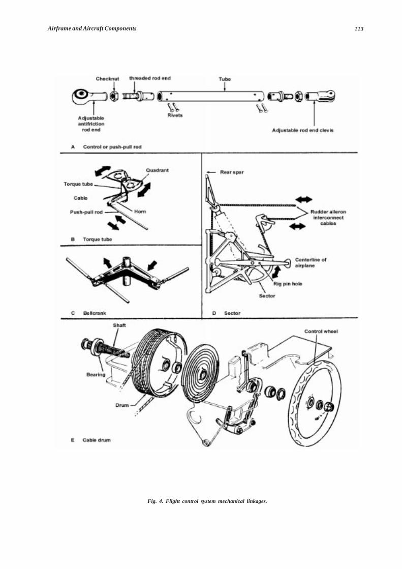
113Airframe and Aircraft Components
Fig. 4. Flight control system mechanical linkages.
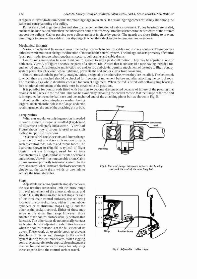
114 L.N.V.M. Society Group of Institutes, Palam Extn., Part-1, Sec-7, Dwarka, New Delhi-77
at regular intervals to determine that the retaining rings are in place. If a retaining ring comes off, it may slide along thecable and cause jamming of a pulley.
Pulleys are used to guide cables and also to change the direction of cable movement. Pulley bearings are sealed,and need no lubrication other than the lubrication done at the factory. Brackets fastened to the structure of the aircraftsupport the pulleys. Cables passing over pulleys are kept in place by guards. The guards are close-fitting to preventjamming or to prevent the cables from slipping off when they slacken due to temperature variations.
Mechanical linkagesVarious mechanical linkages connect the cockpit controls to control cables and surface controls. These devices
either transmit motion or change the direction of motion of the control system. The linkage consists primarily of control(push pull) rods, torque tubes, quadrants, sectors, bell cranks and cable drums.
Control rods are used as links in flight control system to give a push-pull motion. They may be adjusted at one orboth ends. View A of Figure 4 shows the parts of a control rod. Notice that it consists of a tube having threaded rodend, or rod ends. An adjustable anti friction rod end, or rod end clevis, permits attachment of the tube to flight controlsystem parts. The checknut, when tightened, prevents the rod end or clevis from loosening.
Control rods should be perfectly straight, unless designed to be otherwise, when they are installed. The bell crankto which they are attached should be checked for freedom of movement before and after attaching the control rods.The assembly as a whole should be checked for correct alignment. When the rod is fitted with self-aligning bearingsfree rotational movement of the rods must be obtained in all positions.
It is possible for control rods fitted with bearings to become disconnected because of failure of the peening thatretains the ball races in the rod end. This can be avoided by installing the control rods so that the flange of the rod endis interpreted between the ball race and the anchored end of the attaching pin or bolt as shown in Fig. 5.
Another alternative is to place a washer, havinglarger diameter than the hole in the flange, under theretaining nut on the end of the attaching pin or bolt.
Torque tubesWhere an angular or twisting motion is needed
in control system, a torque is installed.(Fig.4c) and4d illustrate a bell crank and a sector. View B ofFigure shows how a torque is used to transmitmotion in opposite directions.
Quadrants, bell cranks, sectors, and drums changedirection of motion and transmit motion to partssuch as control rods, cables and torque tubes. Thequardrant shown in (Fig.4b) is typical of flightcontrol system linkages used by variousmanufacturers. (Fig 4c) and 4d illustrate a bellcrankand a sector. View E illustrates a cable drum. Cabledrums are used primarily in trim tab system. As thetrim tab control wheel is moved clockwise or counterclockwise, the cable drum winds or unwinds toactuate the trim tab cables.
StopsAdjustable and non-adjustable stops (whichever
the case requires are used to limit the throw-rangeor travel movement of the ailerons, elevator, andrudder. Usually there are two sets of stops for eachof the three main control surfaces, one set beinglocated at the control surface, wither in the snubbercylinders or as structural stops (Fig.6), and theother at the cockpit control. Either of these mayserve as the actual limit stop. However, thosesituated at the control surface usually perform thisfunction. The other stops do not normally contacteach other, but are adjusted to a definite clearancewhen the control surface is at the full extent of itstravel. These work as override stops to preventstretching of cables and damage to the controlsystem during violent maneuvers. When riggingcontrol system, refer to the applicable maintenancemanual for the sequence of steps for adjustingthese stops to limit the control surface travel.
Fig.5. Rod end flange interposed between the bearingrace and the end of the attaching bolt.
Fig.6. Adjustable rudder stops.
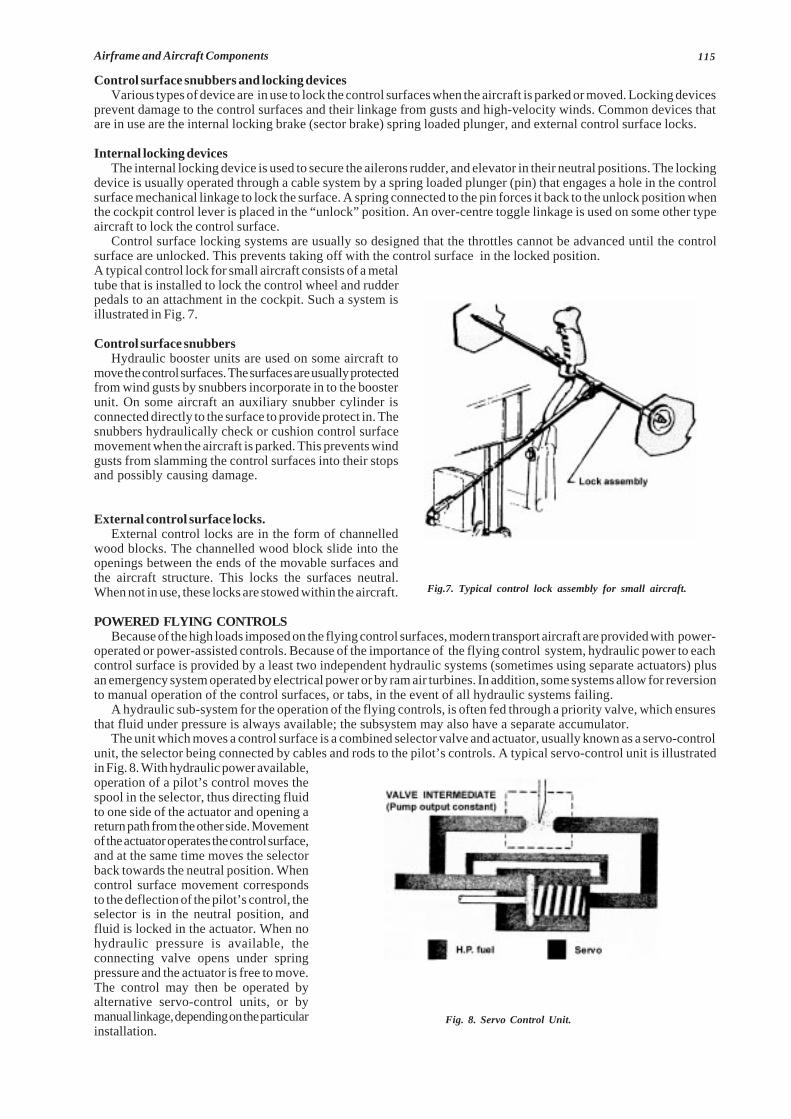
115Airframe and Aircraft Components
Control surface snubbers and locking devicesVarious types of device are in use to lock the control surfaces when the aircraft is parked or moved. Locking devices
prevent damage to the control surfaces and their linkage from gusts and high-velocity winds. Common devices thatare in use are the internal locking brake (sector brake) spring loaded plunger, and external control surface locks.
Internal locking devicesThe internal locking device is used to secure the ailerons rudder, and elevator in their neutral positions. The locking
device is usually operated through a cable system by a spring loaded plunger (pin) that engages a hole in the controlsurface mechanical linkage to lock the surface. A spring connected to the pin forces it back to the unlock position whenthe cockpit control lever is placed in the “unlock” position. An over-centre toggle linkage is used on some other typeaircraft to lock the control surface.
Control surface locking systems are usually so designed that the throttles cannot be advanced until the controlsurface are unlocked. This prevents taking off with the control surface in the locked position.A typical control lock for small aircraft consists of a metaltube that is installed to lock the control wheel and rudderpedals to an attachment in the cockpit. Such a system isillustrated in Fig. 7.
Control surface snubbersHydraulic booster units are used on some aircraft to
move the control surfaces. The surfaces are usually protectedfrom wind gusts by snubbers incorporate in to the boosterunit. On some aircraft an auxiliary snubber cylinder isconnected directly to the surface to provide protect in. Thesnubbers hydraulically check or cushion control surfacemovement when the aircraft is parked. This prevents windgusts from slamming the control surfaces into their stopsand possibly causing damage.
External control surface locks.External control locks are in the form of channelled
wood blocks. The channelled wood block slide into theopenings between the ends of the movable surfaces andthe aircraft structure. This locks the surfaces neutral.When not in use, these locks are stowed within the aircraft.
POWERED FLYING CONTROLSBecause of the high loads imposed on the flying control surfaces, modern transport aircraft are provided with power-
operated or power-assisted controls. Because of the importance of the flying control system, hydraulic power to eachcontrol surface is provided by a least two independent hydraulic systems (sometimes using separate actuators) plusan emergency system operated by electrical power or by ram air turbines. In addition, some systems allow for reversionto manual operation of the control surfaces, or tabs, in the event of all hydraulic systems failing.
A hydraulic sub-system for the operation of the flying controls, is often fed through a priority valve, which ensuresthat fluid under pressure is always available; the subsystem may also have a separate accumulator.
The unit which moves a control surface is a combined selector valve and actuator, usually known as a servo-controlunit, the selector being connected by cables and rods to the pilot’s controls. A typical servo-control unit is illustratedin Fig. 8. With hydraulic power available,operation of a pilot’s control moves thespool in the selector, thus directing fluidto one side of the actuator and opening areturn path from the other side. Movementof the actuator operates the control surface,and at the same time moves the selectorback towards the neutral position. Whencontrol surface movement correspondsto the deflection of the pilot’s control, theselector is in the neutral position, andfluid is locked in the actuator. When nohydraulic pressure is available, theconnecting valve opens under springpressure and the actuator is free to move.The control may then be operated byalternative servo-control units, or bymanual linkage, depending on the particularinstallation.
Fig.7. Typical control lock assembly for small aircraft.
Fig. 8. Servo Control Unit.

116 L.N.V.M. Society Group of Institutes, Palam Extn., Part-1, Sec-7, Dwarka, New Delhi-77
An alternative method of operating the flying controls is by means of self-contained powered flying control units(PFCU’S). Control surfaces are divided into sections, and each section is operated by a separated PFCU, thus providingduplication to guard against failure of a unit. Each unit is controlled by mechanical linkage from the pilot’s controls andauto stabilizer. The mechanical input rod to each unit is telescopic and spring loaded, so that failure of one PFCU willnot prevent operation of the associated control system. In the event failure, or when a unit is inoperative, the actuatingram is mechanically locked in the neutral position, thus preventing movement of the associated section of the controlsurface. Actual operation is basically similar to that of the self-contained hydraulic system, and is not connected withthe main hydraulic system, or with other PFCU’s. The main body of each PFCU acts as a reservoir, and houses all thecomponents necessary for operation of the unit, including electrically driven pumps and hydraulic actuator.
� � �
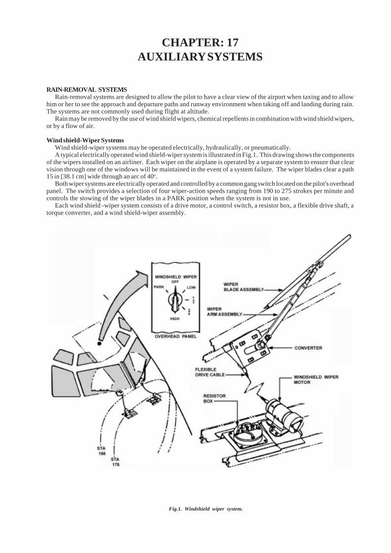
117Airframe and Aircraft Components
CHAPTER: 17AUXILIARY SYSTEMS
RAIN-REMOVAL SYSTEMSRain-removal systems are designed to allow the pilot to have a clear view of the airport when taxing and to allow
him or her to see the approach and departure paths and runway environment when taking off and landing during rain.The systems are not commonly used during flight at altitude.
Rain may be removed by the use of wind shield wipers, chemical repellents in combination with wind shield wipers,or by a flow of air.
Wind shield-Wiper SystemsWind shield-wiper systems may be operated electrically, hydraulically, or pneumatically.A typical electrically operated wind shield-wiper system is illustrated in Fig.1. This drawing shows the components
of the wipers installed on an airliner. Each wiper on the airplane is operated by a separate system to ensure that clearvision through one of the windows will be maintained in the event of a system failure. The wiper blades clear a path15 in [38.1 cm] wide through an arc of 40o.
Both wiper systems are electrically operated and controlled by a common gang switch located on the pilot's overheadpanel. The switch provides a selection of four wiper-action speeds ranging from 190 to 275 strokes per minute andcontrols the stowing of the wiper blades in a PARK position when the system is not in use.
Each wind shield -wiper system consists of a drive motor, a control switch, a resistor box, a flexible drive shaft, atorque converter, and a wind shield-wiper assembly.
Fig.1. Windshield wiper system.
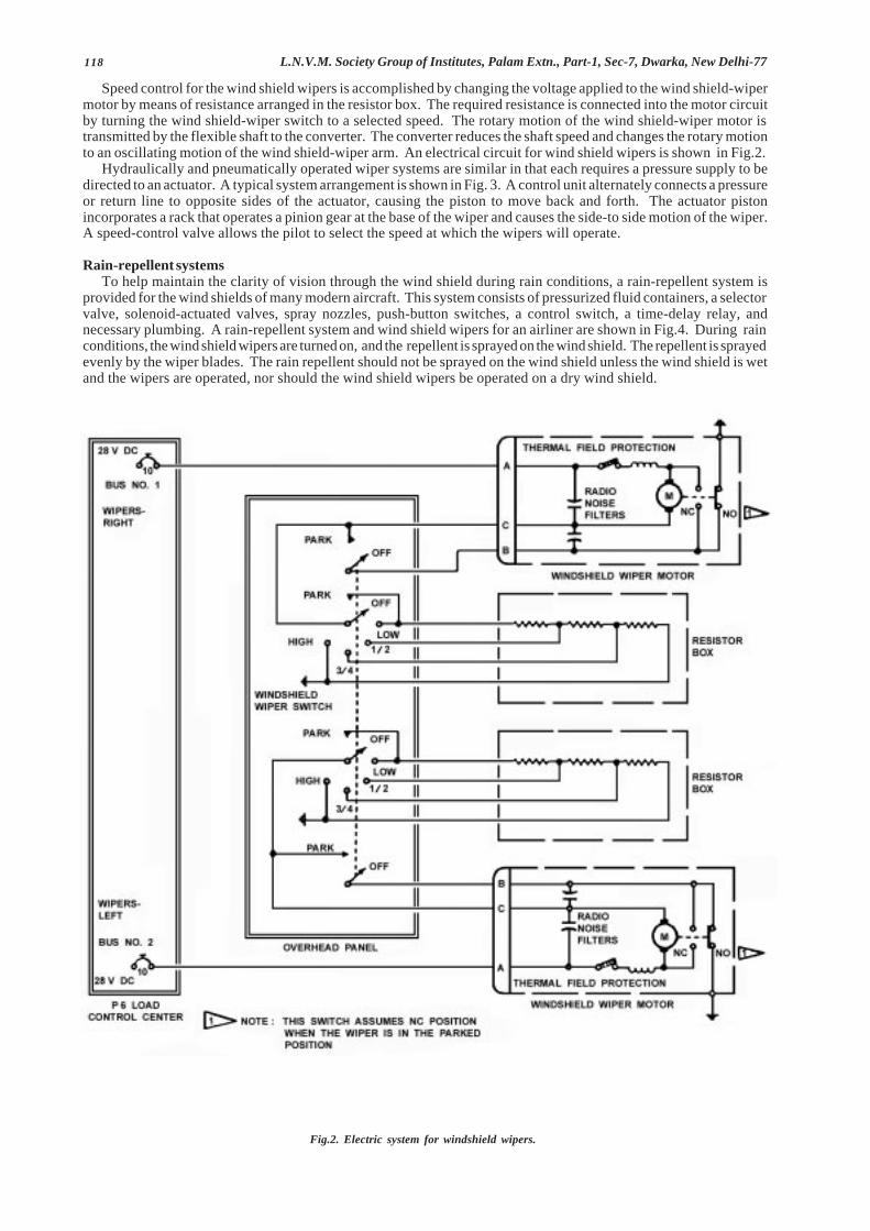
118 L.N.V.M. Society Group of Institutes, Palam Extn., Part-1, Sec-7, Dwarka, New Delhi-77
Speed control for the wind shield wipers is accomplished by changing the voltage applied to the wind shield-wipermotor by means of resistance arranged in the resistor box. The required resistance is connected into the motor circuitby turning the wind shield-wiper switch to a selected speed. The rotary motion of the wind shield-wiper motor istransmitted by the flexible shaft to the converter. The converter reduces the shaft speed and changes the rotary motionto an oscillating motion of the wind shield-wiper arm. An electrical circuit for wind shield wipers is shown in Fig.2.
Hydraulically and pneumatically operated wiper systems are similar in that each requires a pressure supply to bedirected to an actuator. A typical system arrangement is shown in Fig. 3. A control unit alternately connects a pressureor return line to opposite sides of the actuator, causing the piston to move back and forth. The actuator pistonincorporates a rack that operates a pinion gear at the base of the wiper and causes the side-to side motion of the wiper.A speed-control valve allows the pilot to select the speed at which the wipers will operate.
Rain-repellent systemsTo help maintain the clarity of vision through the wind shield during rain conditions, a rain-repellent system is
provided for the wind shields of many modern aircraft. This system consists of pressurized fluid containers, a selectorvalve, solenoid-actuated valves, spray nozzles, push-button switches, a control switch, a time-delay relay, andnecessary plumbing. A rain-repellent system and wind shield wipers for an airliner are shown in Fig.4. During rainconditions, the wind shield wipers are turned on, and the repellent is sprayed on the wind shield. The repellent is sprayedevenly by the wiper blades. The rain repellent should not be sprayed on the wind shield unless the wind shield is wetand the wipers are operated, nor should the wind shield wipers be operated on a dry wind shield.
Fig.2. Electric system for windshield wipers.
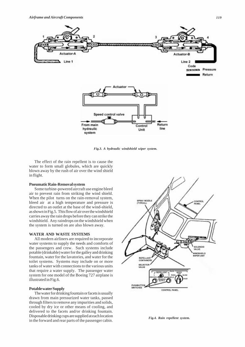
119Airframe and Aircraft Components
The effect of the rain repellent is to cause thewater to form small globules, which are quicklyblown away by the rush of air over the wind shieldin flight.
Pneumatic Rain-Removal systemSome turbine-powered aircraft use engine bleed
air to prevent rain from striking the wind shield.When the pilot turns on the rain-removal system,bleed air at a high temperature and pressure isdirected to an outlet at the base of the wind-shield,as shown in Fig.5. This flow of air over the windshieldcarries away the rain drops before they can strike thewindshield. Any raindrops on the windshield whenthe system is turned on are also blown away.
WATER AND WASTE SYSTEMSAll modern airliners are required to incorporate
water systems to supply the needs and comforts ofthe passengers and crew. Such systems includepotable (drinkable) water for the galley and drinkingfountain, water for the lavatories, and water for thetoilet systems. Systems may include on or moretanks of water with connections to the various unitsthat require a water supply. The passenger watersystem for one model of the Boeing 727 airplane isillustrated in Fig.6.
Potable water SupplyThe water for drinking fountain or facets is usually
drawn from main pressurized water tanks, passedthrough filters to remove any impurities and solids,cooled by dry ice or other means of cooling, anddelivered to the facets and/or drinking fountain.Disposable drinking cups are supplied at each locationin the forward and rear parts of the passenger cabin.
Fig.3. A hydraulic windshield wiper system.
Fig.4. Rain repellent system.
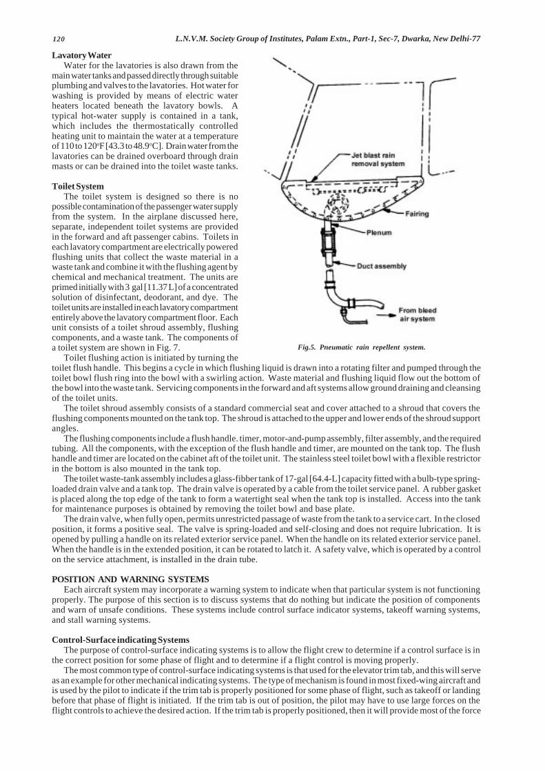
120 L.N.V.M. Society Group of Institutes, Palam Extn., Part-1, Sec-7, Dwarka, New Delhi-77
Lavatory WaterWater for the lavatories is also drawn from the
main water tanks and passed directly through suitableplumbing and valves to the lavatories. Hot water forwashing is provided by means of electric waterheaters located beneath the lavatory bowls. Atypical hot-water supply is contained in a tank,which includes the thermostatically controlledheating unit to maintain the water at a temperatureof 110 to 120oF [43.3 to 48.9oC]. Drain water from thelavatories can be drained overboard through drainmasts or can be drained into the toilet waste tanks.
Toilet SystemThe toilet system is designed so there is no
possible contamination of the passenger water supplyfrom the system. In the airplane discussed here,separate, independent toilet systems are providedin the forward and aft passenger cabins. Toilets ineach lavatory compartment are electrically poweredflushing units that collect the waste material in awaste tank and combine it with the flushing agent bychemical and mechanical treatment. The units areprimed initially with 3 gal [11.37 L] of a concentratedsolution of disinfectant, deodorant, and dye. Thetoilet units are installed in each lavatory compartmententirely above the lavatory compartment floor. Eachunit consists of a toilet shroud assembly, flushingcomponents, and a waste tank. The components ofa toilet system are shown in Fig. 7.
Toilet flushing action is initiated by turning thetoilet flush handle. This begins a cycle in which flushing liquid is drawn into a rotating filter and pumped through thetoilet bowl flush ring into the bowl with a swirling action. Waste material and flushing liquid flow out the bottom ofthe bowl into the waste tank. Servicing components in the forward and aft systems allow ground draining and cleansingof the toilet units.
The toilet shroud assembly consists of a standard commercial seat and cover attached to a shroud that covers theflushing components mounted on the tank top. The shroud is attached to the upper and lower ends of the shroud supportangles.
The flushing components include a flush handle. timer, motor-and-pump assembly, filter assembly, and the requiredtubing. All the components, with the exception of the flush handle and timer, are mounted on the tank top. The flushhandle and timer are located on the cabinet aft of the toilet unit. The stainless steel toilet bowl with a flexible restrictorin the bottom is also mounted in the tank top.
The toilet waste-tank assembly includes a glass-fibber tank of 17-gal [64.4-L] capacity fitted with a bulb-type spring-loaded drain valve and a tank top. The drain valve is operated by a cable from the toilet service panel. A rubber gasketis placed along the top edge of the tank to form a watertight seal when the tank top is installed. Access into the tankfor maintenance purposes is obtained by removing the toilet bowl and base plate.
The drain valve, when fully open, permits unrestricted passage of waste from the tank to a service cart. In the closedposition, it forms a positive seal. The valve is spring-loaded and self-closing and does not require lubrication. It isopened by pulling a handle on its related exterior service panel. When the handle on its related exterior service panel.When the handle is in the extended position, it can be rotated to latch it. A safety valve, which is operated by a controlon the service attachment, is installed in the drain tube.
POSITION AND WARNING SYSTEMSEach aircraft system may incorporate a warning system to indicate when that particular system is not functioning
properly. The purpose of this section is to discuss systems that do nothing but indicate the position of componentsand warn of unsafe conditions. These systems include control surface indicator systems, takeoff warning systems,and stall warning systems.
Control-Surface indicating SystemsThe purpose of control-surface indicating systems is to allow the flight crew to determine if a control surface is in
the correct position for some phase of flight and to determine if a flight control is moving properly.The most common type of control-surface indicating systems is that used for the elevator trim tab, and this will serve
as an example for other mechanical indicating systems. The type of mechanism is found in most fixed-wing aircraft andis used by the pilot to indicate if the trim tab is properly positioned for some phase of flight, such as takeoff or landingbefore that phase of flight is initiated. If the trim tab is out of position, the pilot may have to use large forces on theflight controls to achieve the desired action. If the trim tab is properly positioned, then it will provide most of the force
Fig.5. Pneumatic rain repellent system.
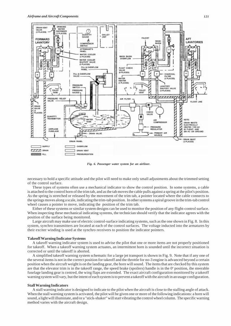
121Airframe and Aircraft Components
necessary to hold a specific attitude and the pilot will need to make only small adjustments about the trimmed settingof the control surface.
These types of systems often use a mechanical indicator to show the control position. In some systems, a cableis attached to the control horn of the trim tab, and as the tab moves the cable pulls against a spring at the pilot's position.As the spring is stretched or released by the movement of the trim tab, a pointer located where the cable connects tothe springs moves along a scale, indicating the trim-tab position. In other systems a spiral groove in the trim-tab controlwheel causes a pointer to move, indicating the position of the trim tab.
Either of these systems or similar system designs can be used to monitor the position of any flight-control surface.When inspecting these mechanical indicating systems, the technician should verify that the indicator agrees with theposition of the surface being monitored.
Large aircraft may make use of electric control-surface indicating systems, such as the one shown in Fig. 8. In thissystem, synchro transmitters are located at each of the control surfaces. The voltage inducted into the armatures bytheir exciter winding is used at the synchro receivers to position the indicator pointers.
Takeoff Warning Indicator SystemsA takeoff warning indicator system is used to advise the pilot that one or more items are not properly positioned
for takeoff. When a takeoff warning system actuates, an intermittent horn is sounded until the incorrect situation iscorrected or until the takeoff is aborted.
A simplified takeoff warning system schematic for a large jet transport is shown in Fig. 9. Note that if any one ofthe several items is not in the correct position for takeoff and the throttle for no-3 engine is advanced beyond a certainposition when the aircraft weight is on the landing gear, the horn will sound. The items that are checked by this systemare that the elevator trim is in the takeoff range, the speed brake (spoilers) handle is in the 0o position, the steerablefuselage landing gear is centred, the wing flaps are extended. The exact aircraft configuration monitored by a takeoffwarning system will vary, but the intent of each system is to prevent a takeoff with the aircraft in an usage configuration.
Stall Warning IndicatorsA stall warning indicator is designed to indicate to the pilot when the aircraft is close to the stalling angle of attack.
When the stall warning system is activated, the pilot will be given one or more of the following indications: a horn willsound, a light will illuminate, and/or a "stick-shaker" will start vibrating the control wheel column. The specific warningmethod varies with the aircraft design.
Fig. 6. Passenger water system for an airliner.
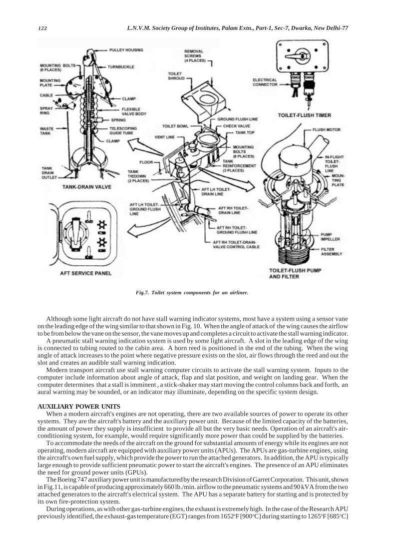
122 L.N.V.M. Society Group of Institutes, Palam Extn., Part-1, Sec-7, Dwarka, New Delhi-77
Although some light aircraft do not have stall warning indicator systems, most have a system using a sensor vaneon the leading edge of the wing similar to that shown in Fig. 10. When the angle of attack of the wing causes the airflowto be from below the vane on the sensor, the vane moves up and completes a circuit to activate the stall warning indicator.
A pneumatic stall warning indication system is used by some light aircraft. A slot in the leading edge of the wingis connected to tubing routed to the cabin area. A horn reed is positioned in the end of the tubing. When the wingangle of attack increases to the point where negative pressure exists on the slot, air flows through the reed and out theslot and creates an audible stall warning indication.
Modern transport aircraft use stall warning computer circuits to activate the stall warning system. Inputs to thecomputer include information about angle of attack, flap and slat position, and weight on landing gear. When thecomputer determines that a stall is imminent , a stick-shaker may start moving the control columns back and forth, anaural warning may be sounded, or an indicator may illuminate, depending on the specific system design.
AUXILIARY POWER UNITSWhen a modern aircraft's engines are not operating, there are two available sources of power to operate its other
systems. They are the aircraft's battery and the auxiliary power unit. Because of the limited capacity of the batteries,the amount of power they supply is insufficient to provide all but the very basic needs. Operation of an aircraft's air-conditioning system, for example, would require significantly more power than could be supplied by the batteries.
To accommodate the needs of the aircraft on the ground for substantial amounts of energy while its engines are notoperating, modern aircraft are equipped with auxiliary power units (APUs). The APUs are gas-turbine engines, usingthe aircraft's own fuel supply, which provide the power to run the attached generators. In addition, the APU is typicallylarge enough to provide sufficient pneumatic power to start the aircraft's engines. The presence of an APU eliminatesthe need for ground power units (GPUs).
The Boeing 747 auxiliary power unit is manufactured by the research Division of Garret Corporation. This unit, shownin Fig.11, is capable of producing approximately 660 lb./min. airflow to the pneumatic systems and 90 kVA from the twoattached generators to the aircraft's electrical system. The APU has a separate battery for starting and is protected byits own fire-protection system.
During operations, as with other gas-turbine engines, the exhaust is extremely high. In the case of the Research APUpreviously identified, the exhaust-gas temperature (EGT) ranges from 1652oF [900oC] during starting to 1265oF [685oC]
Fig.7. Toilet system components for an airliner.
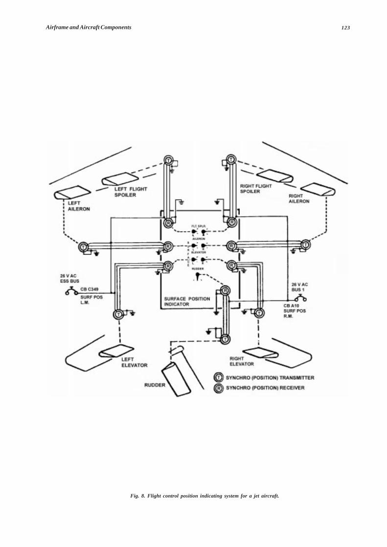
123Airframe and Aircraft Components
Fig. 8. Flight control position indicating system for a jet aircraft.
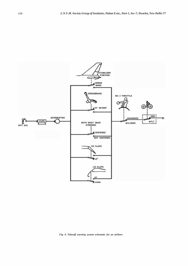
124 L.N.V.M. Society Group of Institutes, Palam Extn., Part-1, Sec-7, Dwarka, New Delhi-77
Fig. 9. Takeoff warning system schematic for an airliner.
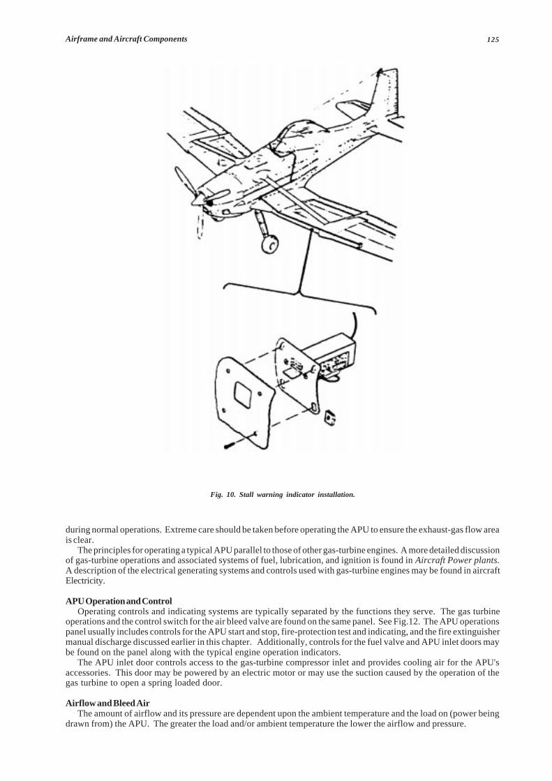
125Airframe and Aircraft Components
during normal operations. Extreme care should be taken before operating the APU to ensure the exhaust-gas flow areais clear.
The principles for operating a typical APU parallel to those of other gas-turbine engines. A more detailed discussionof gas-turbine operations and associated systems of fuel, lubrication, and ignition is found in Aircraft Power plants.A description of the electrical generating systems and controls used with gas-turbine engines may be found in aircraftElectricity.
APU Operation and ControlOperating controls and indicating systems are typically separated by the functions they serve. The gas turbine
operations and the control switch for the air bleed valve are found on the same panel. See Fig.12. The APU operationspanel usually includes controls for the APU start and stop, fire-protection test and indicating, and the fire extinguishermanual discharge discussed earlier in this chapter. Additionally, controls for the fuel valve and APU inlet doors maybe found on the panel along with the typical engine operation indicators.
The APU inlet door controls access to the gas-turbine compressor inlet and provides cooling air for the APU'saccessories. This door may be powered by an electric motor or may use the suction caused by the operation of thegas turbine to open a spring loaded door.
Airflow and Bleed AirThe amount of airflow and its pressure are dependent upon the ambient temperature and the load on (power being
drawn from) the APU. The greater the load and/or ambient temperature the lower the airflow and pressure.
Fig. 10. Stall warning indicator installation.
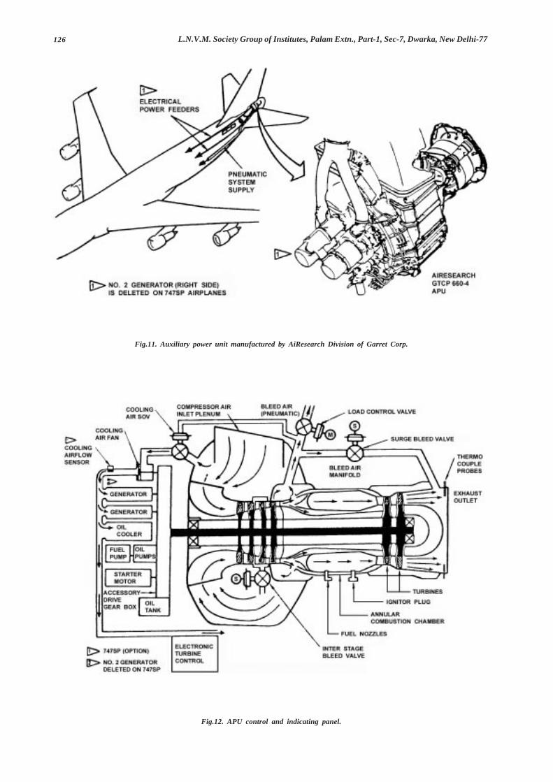
126 L.N.V.M. Society Group of Institutes, Palam Extn., Part-1, Sec-7, Dwarka, New Delhi-77
Fig.11. Auxiliary power unit manufactured by AiResearch Division of Garret Corp.
Fig.12. APU control and indicating panel.
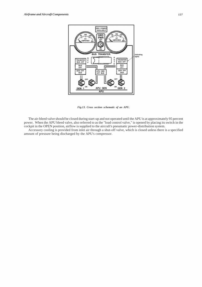
127Airframe and Aircraft Components
The air-bleed valve should be closed during start-up and not operated until the APU is at approximately 95 percentpower. When the APU bleed valve, also referred to as the "load control valve," is opened by placing its switch in thecockpit in the OPEN position, airflow is supplied to the aircraft's pneumatic power-distribution system.
Accessory cooling is provided from inlet air through a shut-off valve, which is closed unless there is a specifiedamount of pressure being discharged by the APU's compressor.
� � �
Fig.13. Cross section schematic of an APU.
128 L.N.V.M. Society Group of Institutes, Palam Extn., Part-1, Sec-7, Dwarka, New Delhi-77
CHAPTER: 18FIRE-GENERAL PRECAUTIONS
PREVENTION OF FIRE ON THE GROUNDPersonnel engaged in the maintenance, overhaul and repair of aircraft, should be fully conversant with the operation
of fire protection equipment provided and the action to be taken in the event of discovering a fire. Supervisors shouldsatisfy themselves that all reasonable safety precautions are taken and that all apparatus is completely serviceable.Personnel should not wear footwear, with exposed iron or steel studs, nails or tips in hangars, fuelling and de-fuellingareas, and aircraft movement areas, and it is recommended that matches or other means of ignition should not be carried.
Fuelling OperationsPersonnel concerned with fuelling should be fully conversant with the guidance material, with local aerodrome
instructions and with the safety precautions detailed in the relevant aircraft Maintenance Manual. Fuelling should onlybe carried out at a site approved by the aerodrome authority, and the out at a site approved by the aerodrome authority,and the precautions should be observed.
Fuelling ZonesFuelling zones should be established before fuelling commences. These zones should be regarded as extending
at least 6m (20ft) readily from the filling and venting points on the aircraft and fuelling equipment. Within this zone,smoking, the use of naked lights and the operation of switches which are not of an approved pattern should be forbidden.
a. Unless fuelling takes place in a designated no smoking area, “No Smoking” signs should be displayed not lessthan 15m (50ft) from the fuelling equipment and aircraft tank vents.
b. Auxiliary Power Units (APUs) which have an exhaust discharging into the zone should, if required to be inoperation during fuelling, be started before filler caps are removed or fuelling connections made. If an APU isstopped for any reason during a fuelling operation it should not be started again until fuelling has ceased andthere is no danger of igniting fuel vapours.
c. Ground Power Units (GPUs) should be located as far as practical from aircraft fuelling points and vents, andshould not be connected or disconnected while fuelling is in progress.
d. Fire extinguishers should be located so as to be readily accessible.
Precautions Prior To FuellingBefore the transfer of fuel commences, the following procedure should be carried out:-a. The aircraft should be connected to an effective earthing point and to the fuelling equipment.b. When over wing fuelling, the nozzle of the hose should be bonded to the aircraft structure before removing the
tank filler cap. When fuelling from hand-operated equipment, including pumping from cans or drums, similarprecautions should be taken to bond the pumping equipment, hose nozzle and containers. If funnels are usedthey too should be bonded to the nozzle or can and to the aircraft. If a chamois leather filter is used, the funnel,and all metal parts securing the leather, should be included in the bonding circuit.
c. When pressure fuelling, the fuel tank pressure relief valves should, if possible, be checked for correct operation,and the bonding lead on the fuelling hose should be connected to the receptacle, located adjacent to the fuellingpoint, before connecting the nozzle.
Precautions During Fuel Transfera. When over wing fuelling, the amount of fuel required should be determined and the quantity of fuel delivered
should be regulated so that no overflow occurs. Fuel should not be splashed nor allowed to run into the aircraftstructure.
b. When pressure fuelling, any fuel levelling devices between tanks should be operated as necessary. The correctsequence of operations is essential to avoid damage to tanks and subsequent leakage of fuel or vapour.
Precautions After FuellingWhen the transfer of fuel is completed, the bonding wires should not be removed until the filler caps have been refitted
or the pressure fuelling hose disconnected, as appropriate.
Work On aircraft During FuellingWhilst fuelling is in progress, servicing, maintenance, test and repair activities within the fuelling zone should be
closely controlled.a. All ground equipment such as trestles, jacks, steps etc., should be moved clear of the aircraft, to prevent damage
to the aircraft as it settles because of the weight of fuel being uplifted.b. The main aircraft engines should not be operated.c. Only those electrical circuits essential to the fuelling operation should be switched on, except that some
operators may permit certain specified maintenance work to be carried out during kerosene fuelling. Themaintenance permitted is usually restricted to the replacement of complete unit assemblies. Testing and
129Airframe and Aircraft Components
functioning of defined systems and equipment may be continued unless fuel spillage occurs or fuellingequipment becomes defective. No maintenance work may be permitted on aircraft using fuels which present ahigher degree of fire hazard.
d. Strobe lighting should not be operated.e. The engines of vehicles normally employed for servicing aircraft, including those on electrically powered
vehicles, should not be run within the fuelling zone unless they have been designed for the purpose. All vehicles,their engines and equipment, should be subjected to regular inspection and maintenance to preserve their safetycharacteristics.
f. All connections between ground equipment and an aircraft should be made before fuelling equipment isconnected, and should not be broken until fuelling has been completed.
g. Battery trolleys may be used within the fuelling zone provided that connection is made to the aircraft beforefuelling equipment is connected. The circuit should remain unbroken until fuelling has ceased.
h. Vehicles operating in the fuelling zone should not pass under or park beneath an aircraft unless specificallyrequired to do so for maintenance or fuelling purposes. A clear exit path should be maintained.
i. Aircraft combustion heaters should not be used.k. Maintenance work which may create a source of ignition should not be carried out in the vicinity of tanks or
fuelling equipment.l. All hand torches and inspection lamps, and their cable connections, used within the fuelling zone, should be
of certified “flameproof” or ‘intrinsically safe’ type.m. Only authorised persons and vehicles should be permitted within the fuelling zone and the numbers should be
kept to a minimum.
Special Hazardsa. Aircraft should not be fuelled within 30m (100ft) of radar equipment under test, or in use in aircraft or ground
installations.b. When any part of an aircraft landing gear, e.g. the wheels, tyres and brakes, appears overheated, the Aerodrome
Fire Service should be called and fuelling should not take place until the heat has dissipated.c. Extreme caution should be exercised when fuelling during electrical storms. Fuelling should be suspended during
severs electrical disturbances in the vicinity of the aerodrome.d. The use of photographic flash bulbs and electronic flash equipment within 6m (20ft) of the filling or venting points
of aircraft or fuelling equipment, should not be permitted.
Spillage Of FuelThe actions to be taken in the event of a spillage of fuel will depend on the size and location of the spillage, the type
of fuel involved, and prevailing weather conditions.a. If, despite care, fuel is inadvertently spilled in the aircraft structure, it should be cleared before the main aircraft
engines are started, Lowering the flaps may accelerate drainage in some cases. Flight should be delayed to permitthe evaporation of spillage, and air blowers should be utilised as necessary.
b. In the case of a minor spillage of fuel on the ground, all liquid should be mopped up and the area allowed to dryout before starting any aircraft or vehicle engines in the vicinity.
c. In the case of major spillage of fuel (i.e. covering an area greater than 5m2 (55 ft2), action should immediately betaken to stop the flow of fuel, to evacuate all persons from the area and to notify the Aerodrome Fire Service.
d. Fuel should not be washed into drains or culverts, but if such contamination does occur, large-scale waterflushing should be carried out and the local water authority notified. Absorbent cleaning agents or emulsioncompounds should be used to absorb spilled fuel, the contaminated absorbent being placed in suitablecontainers and removed to a safe location for disposal. The selection of tools and equipment to be used inremoving spilled fuel and disposing of contaminated materials should have regard to minimising the risk ofignition.
Work In HangarsBefore commencing any inspection, overhaul or repair work involving the use of possible ignition sources in the
vicinity of the fuel tanks, all tanks should be drained. De-fuelling should be carried out in the open air, by means ofa fuel tanker utilising the pressure fuelling/de-fuelling connections on the aircraft, or by draining the tanks into suitablecontainers. In either case, adequate bonding precautions should be taken, the tanker or containers being bonded tothe aircraft and the ground before draining commences. Care should be taken to avoid spilling fuel onto the ground,and containers should be sealed immediately after filling. To avoid danger form sparking between containers and groundcontacts, the aircraft should normally be moved form the site first.
The draining of fuel tanks does not render them free from fire risk, as they will contain fuel vapour. It is thereforenecessary to purge tanks of vapour before subjecting them to inspection or repair involving the use of heat, electricalequipment or other sources of ignition. The safety precautions applicable to the inspection and repair of tanks areincluded.
Special care is necessary during fuel flow testing, and foam or CO2 type extinguishers should always be available
whilst this work is in progress. The use of an enclosed flow test rig, similar to that described.Electrical equipment used during maintenance work, e.g. portable lighting equipment, electric drills, soldering irons,
etc., should be maintained in good condition to avoid generating sparks, and in any case this equipment should notbe used when flammable vapours are present in the atmosphere. For work in areas where heavy fumes are present, e.g.
130 L.N.V.M. Society Group of Institutes, Palam Extn., Part-1, Sec-7, Dwarka, New Delhi-77
inside fuel tanks, flameproof torches must be used. Care should be taken that no flammable fluid is splashed on nakedbulbs or other hot surfaces as spontaneous ignition may follow. Low voltage electrical supplies for inspection lamps,etc., are advantageous.
As far as possible only non-flammable cleaning fluids and paint strippers should be used, but if the use of solventsgiving off flammable vapours is unavoidable, they should be handled with care and if spilt, should be wiped upimmediately. During the use of such fluids the aircraft electrical system should be made inoperative with, for preference,the aircraft batteries removed.
In certain aircraft, special battery lead stowages are embodied. These should be utilised in accordance with theappropriate instructions contained in the Maintenance Manual.
The spraying of large surfaces with dope or paint should be carried out in a properly constructed and equipped sprayshop. When touching up small areas, all electrical apparatus worked from a mains supply should be switched off orremoved from the vicinity.
Open containers of dirty oil, fuel, dope or solvents should not be stored in aircraft hangars and should be removedfrom the vicinity of aircraft as soon as possible, otherwise accumulations of flammable vapour may result.
Magnesium and titanium swarf should be completely removed after drilling or machining operations. Special drypowder extinguishants, which are usually known by a trade name, should be used on fires of these combustible metals;water must not be used. The extinguishants form a crust or skin over the burning metal and thus exclude air.
Before permitting the refitting of floor panels or inspection covers, inspectors should ensure that the bays are cleanand free all foreign matter, that all drains are unobstructed, and all applications of primers, sealing compounds, etc.,in the boxed up area are dry. In addition, all electrical connections, fuse box covers, etc., should be checked, and thesystems functioned, and if the bay houses part of the flying control system duplicate inspection of the flying controlsshould be carried out before fitting the covers or panels.
MAINTENANCE AND FIRE PREVENTIONThe following recommendations give guidance on maintenance practices which will reduce the risk of fires occurring
in flight or when ground running engines.
Power PlantFaulty assembly or mechanical failure of engines or power-plant components can cause fire, and careful inspection
is therefore essential to ensure that fractures, cracks or leaks are detected and rectified.Attention should be given to main engine and APU starter systems, and in particular, to ignition harnesses and to
high energy igniter plugs and leads in turbine engines. Maintenance instructions must be carefully carried out inaccordance with the engine Maintenance Manual.
Pipes carrying flammable fluids are routed by design as far from exhaust systems and electrical apparatus as theinstallation permits, and, if disturbed, should be re-installed so that the original distances form such sources of ignitionare not reduced. Great care must always be exercised to ensure that pipes are in good condition, are appropriately colourcoded, are adequately clipped and bonded, and that unions are correctly secured so that leaks cannot occur, and thatdrains are clear.
It is most important to trace the source of any flammable fluid leakage and to rectify if immediately. Kerosene,lubricating oil, gasolene and most hydraulic fluids will ignite spontaneously if in contact with hot surfaces, such asexhaust pipes, combustion chambers, jet pipes and overheated brakes. Gasolene at ambient temperatures and keroseneat elevated temperatures will vaporise and form a combustible mixture with air, which may be ignited by sparks fromelectrical equipment or accumulations of static electricity. Fuel and oil drains should be checked for blockage and therouting of the pipes must be clear of cowlings and brake systems. Cowlings should be kept clean to obviateaccumulations of flammable fluids, greases and dirt.
The flame traps or shutters of air intake systems must always be in good condition. Flame traps will burn if combustiblesludge is allowed to seal opening in firewalls must always be refitted carefully and renewed if damaged. Gaps throughor around a firewalls are not permitted. Seals must be securely fixed in position, approved sealants should be renewedas necessary, and distorted or damaged cowlings must be repaired or renewed.
The power plant bonding system is an important safeguard against fire and all bonding connections should beinspected frequently according to the recommendations.
A major failure, such as the fracture of a cylinder or induction manifold on a piston engine (particularly a supercharged engine) is a serious matter, as air/fuel vapour mixture may be discharged and contact a hot surface in the powerplant area, where ignition could occur. Careful visual examination may reveal minor defects before the danger of acomplete breakdown arises.
Shortage of coolant in liquid-cooled piston engines will result in overheating with a grave risk of mechanical failureof the engine causing a fire. It follows that careful maintenance of cooling systems is an aid to fire prevention.
Cracked exhaust manifolds, pipes, ejectors, or turbine engine combustion chambers may allow hot gases or torchingflame to impinge on vulnerable parts of the power plant installation, either causing fire directly or giving rise tomechanical failure which may start a fire. Exhaust systems and combustion chambers should therefore receive verycareful examination.
Engine vibration is generally an indication of a serious defect and can also result in the cracking of pipes or leakingof high pressure hoses and loosening of pipe connections.
It is most important that all the appropriate fire precautions are taken during the operation of auxiliary power unitswhilst the aircraft is on the ground. Intakes and exhausts must be free from obstruction. Temperature and warningindicators should be observed and action taken accordingly.
131Airframe and Aircraft Components
A contributory cause of fires in engine bays is the saturation of flexible-pipe lagging by flammable liquids. Thiscan occur when the outer covering (e.g. sleeveing of neoprene or rubber) has been damaged or has deteriorated, allowingseepage into the lagging. This condition can be detected by blistering or a soggy feel, as distinct from the hard feelof unsaturated pipes. If pipes are in a saturated condition they should be renewed.
ENGINE RUNNING PRECAUTIONSFires during engine starting and running can be avoided by observing the correct drill given in the relevant Manuals
for the aircraft and engine concerned. General guidance on some important points is given in the following paragraphs:-a. Whilst engines are being started and ground run, fire extinguishing apparatus, preferably of the CO
2 trolley type
with extending applicator and under the control of trained and experienced personnel, should be positioned nearthe aircraft. Additionally, a good communications system should be arranged between the cockpit and ground.
b. Persons in control of engine ground running should be familiar with the approved ground running instructionsin the appropriate Manuals and with the correct fire drill procedure.
Piston EnginesCare should be exercised when priming piston engines preparatory to starting, particularly when an electrical priming
pump is used or when priming is carried out by pumping the throttle (to operate the carburettor accelerator pump). Overpriming can cause an excess of fuel in the engine, and could result in an intake fire.
When excess-fuel conditions exist and an engine fails to start (a common occurrence when engines are hot) the fuelcock should be turned OFF (or the fuel cut-out closed) and the throttle should be fully opened. After ensuring thatall ignition switches including booster coil switches are OFF, the engine should be turned. Most types of engines canbe turned in the running direction by the propeller or starter, but when this has been done, precautions should be takento dispel any accumulations of fuel in the exhaust system. On some small engines the propeller can be used to turnthe engine in the reverse direction of rotation to expel the over rich fuel-air mixture through the air intake.
If an air intake fire occurs before the engine picks up, a previously agree signal should be made to the person at thecontrols, who should immediately turn off the appropriate engine fuel cock; it is often recommended to continue to motorthe engine on the starter so that the burning fuel is drawn into the engine. If the engine picks up and runs, an air intakefire will probably cease without further action, in which case the fuel may be turned on again. Consideration shouldthen be given to any damage which may have been caused to the intake filters by the intake fire.
If an intake fire persists or appears to be serious, a ground CO2 type fire extinguisher should be discharged into the
air intake. Outside action will also be necessary if burning fuel runs form the intake or exhaust on to the ground.Should an engine fire occur whilst ground running, the drill given in the appropriate Manual should be followed.
To help the person in charge of the ground fire fighting equipment, any other operating engines should be shut down.Any practice which promotes accumulation of flammable fluid or vapour inside engine cowlings should be avoided.
Exhaust systems must give complete sealing; flanges, gaskets and air intake sealing must be regularly examined andmaintained. In shutting-down, engines should first be cooled by running at low power for a short period, and fuel cut-outs (if fitted) should be used strictly in accordance with the engine manufacturer operating instructions.
Gas Turbine EnginesThe most frequent cause of fire during starting is the accumulation of fuel in the engine and jet pipe following an
earlier ‘wet start’ (i.e. an unsuccessful attempt to start in which the fuel has failed to ignite and has been distributedthroughout the engine and jet pipe and drained into the lower combustion chambers and drain system). It is necessaryto ensure that the drain system operates correctly, and to drain the vent tank (which has a limited capacity), as advisedby the manufacturer. It is normal practice to carry out a ‘dry run’ (i.e. motor the engine through the starting cycle withthe fuel and ignition turned off) after a wet start before making another attempt to start an engine.
As kerosene spreads readily and does not evaporate quickly a very slight leak is significant and must be remedied.Fuel which may have collected in cavities, cowlings, etc., should be wiped up after maintenance operations before anyattempt is made to start the engines.
If there is any indication of an internal engine fire when an engine is not running the fuel cocks should immediatelybe turned OFF and every attempt made to localise the fire. An outside assistant should discharge a CO
2 or BCF
extinguisher into the intake or jet pipe if necessary.When starting and running gas turbines, particular note should be taken of the jet pipe temperature. If this exceeds
the manufacturer’s limitations, a serious risk of mechanical failure followed by fire may result.
� � �
132 L.N.V.M. Society Group of Institutes, Palam Extn., Part-1, Sec-7, Dwarka, New Delhi-77
CHAPTER: 19FIRE EXTINGUISHING EQUIPMENT
TYPES OF SYSTEMSThe extinguishing systems in general use are the fixed system, the portable system and the mixed system. The term
‘fixed’ refers to a permanently installed system of extinguishant containers, distribution pipes and controls providedfor the protection of power plants and, where applicable, auxiliary power units. In some types of aircraft landing gearwheel bays and baggage compartments.
A portable system refers to the several hand-operated fire extinguishers provided to combat any outbreaks of firein flight crew compartments and passenger cabins.
A mixed system is one used in some aircraft for the protection of baggage and service compartments. The distributionpipeline and spray system is fixed in the appropriate compartment and is coupled to adaptor points to which a handoperated extinguisher may be plugged in.
TYPES OF EXTINGUISHANTThe extinguishants in general use are described in the following paragraphs.
Methyl bromide (M.B.)This extinguishant boils at 4.60C and is commonly used in fixed systems, particularly for the protection of power
plants. Because of its toxicity, Methyl Bromide should not be used in confined spaces, flight crew compartments orpassenger cabins. The effects of breathing the vapours may not be immediately apparent, but serious or even fatal aftereffects may be sustained at a later stage.
Bromochlorodifluromethane (B.C.F.)This is semi-toxic extinguishant is particularly effective against electrical and flammable liquid fires. It is used in
power plant systems, and for the protection of auxiliary power units in some aircraft; it is also used in certain types ofportable extinguisher. It becomes gaseous at normal temperatures and condenses to liquid at-4oC (25oF), and can bestored and discharged at moderate pressures. It has little or no corrosive effect, although halogen acids will be formedif its products which have been decomposed by fire come into contact with water, e.g. condensation caused by fire.In contact with fire, B.C.F. volatilises instantly, giving rapid flame extinction with little or no deleterious effect on metallic,wooden, plastic or fabric materials.
Carbon dioxide (CO2)
This gas extinguishant is also effective against electrical and flammable liquid fires and is used principally in portablefire extinguishers. It is noncorrosive and if the concentration needed to extinguish a fire is excessive it can haveappreciable toxic effects. When discharged in a confined space, the vapour cloud can reduce visibility temporarily.
WaterIn many aircraft, certain of the portable fire extinguishers in passenger cabins are of the water type, designed for
combating fires involving ordinary combustible material such as paper, fabric, etc., where the quenching and coolingeffects of water are of prime importance. These extinguishers are not suitable against electrical fires. An anti-freezingagent is normally included to permit operation at temperatures as low as -20oC. Typical examples are the water/glycolextinguisher with 38% of inhibited ethylene glycol, and the ‘wet-water’ extinguisher with glycol, wetting agents toreduce surface tension, and inhibitors to impart anti-corrosive characteristics.
Bromotrifluromethane (B.T.M.)This semi-toxic extinguishant is used in fixed systems for the protection of power plant and auxiliary power units.
It is also widely used in cargo compartment fire suppression systems of some types of aircraft.
Dry ChemicalDry chemical extinguishant takes the form of a non-toxic powder, e.g. potassium bicarbonate, and is used in portable
fire extinguishers fitted in certain types of aircraft. It is very effective against fires involving flammable liquids and freeburning material such as wood, fabrics and paper. Use of the extinguishant against fires in electrical equipment is notrecommended, since it could render contactors and switches un-serviceable which may otherwise be functioningcorrectly in adjacent equipment. It does not have a quenching effect and thereby the dangers of distortion or explosionwhen used on hot surfaces, such as overheated wheel brakes, are minimised. Some dry chemical powders have acorrosive effect on some metals (including aluminium) which may require special attention when cleaning-up after thedischarge of an extinguisher. Dry chemical extinguishers should not be used in flight crew compartments or passengercabins where visibility would be seriously affected both during the discharge of powder and also as a result of itsdeposition on transparencies and instruments.
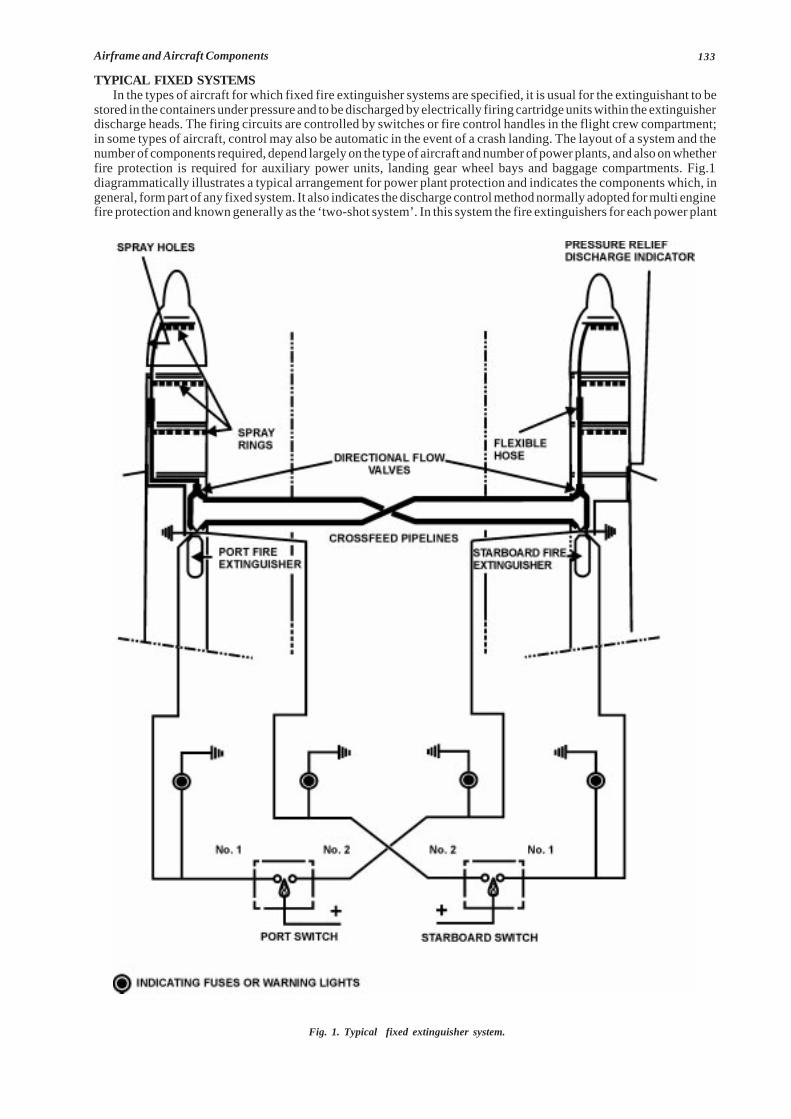
133Airframe and Aircraft Components
TYPICAL FIXED SYSTEMSIn the types of aircraft for which fixed fire extinguisher systems are specified, it is usual for the extinguishant to be
stored in the containers under pressure and to be discharged by electrically firing cartridge units within the extinguisherdischarge heads. The firing circuits are controlled by switches or fire control handles in the flight crew compartment;in some types of aircraft, control may also be automatic in the event of a crash landing. The layout of a system and thenumber of components required, depend largely on the type of aircraft and number of power plants, and also on whetherfire protection is required for auxiliary power units, landing gear wheel bays and baggage compartments. Fig.1diagrammatically illustrates a typical arrangement for power plant protection and indicates the components which, ingeneral, form part of any fixed system. It also indicates the discharge control method normally adopted for multi enginefire protection and known generally as the ‘two-shot system’. In this system the fire extinguishers for each power plant
Fig. 1. Typical fixed extinguisher system.
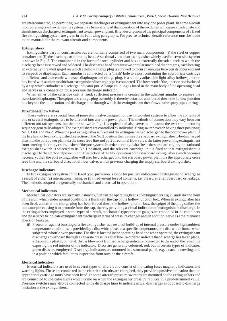
134 L.N.V.M. Society Group of Institutes, Palam Extn., Part-1, Sec-7, Dwarka, New Delhi-77
are interconnected, so permitting two separate discharges of extinguishant into any one poser plant. In some aircraftincorporating crash switches the system may be so arranged that operation of the switches will cause an adequate andsimultaneous discharge of extinguishant to each power plant. Brief descriptions of the principal components of a fixedfire extinguishing system are given in the following paragraphs. For precise technical details reference must be madeto the manuals for the relevant aircraft and components.
ExtinguishersExtinguishers vary in construction but are normally comprised of two main components: (i) the steel or copper
container and (ii) the discharge or operating head. A sectional view of an extinguisher widely used in a two-shot systemis shown in Fig. 2. The container is in the form of a steel cylinder and has an externally threaded neck to which thedischarge head is screwed and soldered. The discharge head contains two annular machined diaphragms, each bearingan externally threaded spigot on which a hollow charge plug is screwed to form an annulus between its inner end andits respective diaphragm. Each annulus is connected by a ‘flash’ hole to a port containing the appropriate cartridgeunit. Below, and concentric with each diaphragm and charge plug, is a radially adjustable light-alloy hollow junctionbox fitted with a union to which an extinguisher discharge pipe is connected. The lower end of the junction box is closedby a cap which embodies a discharge indicator pin. A banjo coupling is fitted in the main body of the operating headand serves as a connection for a pressure discharge indicator.
When either of the cartridge unit is fired, sufficient pressure is created in the adjacent annulus to rupture theassociated diaphragm. The spigot and charge plug assembly is thereby detached and forced down the hollow junctionbox beyond the outlet union and discharge pipe through which the extinguishant then flows to the spray pipes or rings.
Directional Flow ValvesThese valves are a special form of non-return valve designed for use in two-shot systems to allow the contents of
one or several extinguishers to be directed into any one power plant. The methods of connection may vary betweendifferent aircraft systems, but the one shown in Fig. 1 is typical and also serves to illustrate the two-shot operatingsequence generally adopted. The extinguishers are controlled by individual firing switches each having three positions;No.1, OFF and No.2. When the port extinguisher is fired and the extinguisher is discharged to the port power plant. Ifthe fire has not been extinguished, selection of the No.2 position then causes the starboard extinguisher to be dischargedalso into the port power plant via the cross feed line and port directional flow valve, the latter preventing extinguishantfrom entering the empty extinguisher of the port system. In order to extinguish a fire in the starboard engine, the starboardextinguisher switch is selected to its No.1 position, and the relevant cartridge unit is fired so that extinguishant isdischarged to the starboard power plant. If selection of the No.2 position of the starboard extinguisher switch becomesnecessary, then the port extinguisher will also be discharged into the starboard power plant via the appropriate crossfeed line and the starboard directional flow valve, which prevents charging the empty starboard extinguisher.
Discharge IndicatorsIn fire extinguisher system of the fixed type, provision is made for positive indication of extinguisher discharge as
a result of either (a) international firing, or (b) inadvertent loss of contents, i.e. pressure relief overboard or leakage.The methods adopted are generally mechanical and electrical in operation.
Mechanical IndicatorsMechanical indicators are, in many instances, fitted in the operating heads of extinguishers Fig.2., and take the form
of the a pin which under normal conditions is flush with the cap of the hollow junction box. When an extinguisher hasbeen fired, and after the charge plug has been forced down the hollow junction box, the spigot of the plug strikes theindicator pin causing it to protrude from the cap, thereby providing a visual indication of extinguishant discharge. Inthe extinguishers employed in some types of aircraft, mechanical type pressure gauges are embodied in the containersand these serve to indicate extinguishant discharge in terms of pressure changes and, in addition, serve as a maintenancecheck on leakage.
(i) Protection against bursting of a fire extinguisher as a result of build-up of internal pressure under high ambienttemperature conditions, is provided by a disc which fuses at a specific temperature, or a disc which bursts whensubjected to bottle over-pressure. The disc is located in the operating head and when operated, the extinguishantdischarges overboard through a separate pressure relief line. In order to indicate that discharge has taken place,a disposable plastic, or metal, disc is blown out from a discharge indicator connected to the end of the relief lineexposing the red interior of the indicator. Discs are generally coloured, red, but in certain types of indicator,green discs are employed. Discharge indicators are mounted in a structural panel, e.g. a nacelle cowling, andin a position which facilitates inspection from outside the aircraft.
Electrical IndicatorsElectrical indicators are used in several types of aircraft and consist of indicating fuses magnetic indicators and
warning lights. These are connected in the electrical circuits are energised, they provide a positive indication that theappropriate cartridge units have been fired. In some aircraft pressure switches are mounted on the extinguishers andare connected to indicator lights which come on when the extinguisher pressure reduces to a predetermined value.Pressure switches may also be connected in the discharge lines to indicate actual discharges as opposed to dischargeinitiation at the extinguishers.
135Airframe and Aircraft Components
Fig. 2. Fixed type of extinguisher.
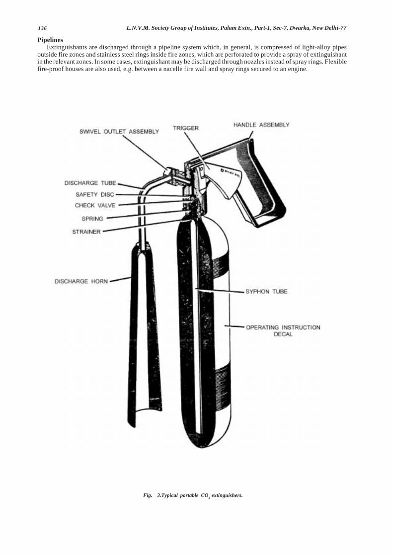
136 L.N.V.M. Society Group of Institutes, Palam Extn., Part-1, Sec-7, Dwarka, New Delhi-77
PipelinesExtinguishants are discharged through a pipeline system which, in general, is compressed of light-alloy pipes
outside fire zones and stainless steel rings inside fire zones, which are perforated to provide a spray of extinguishantin the relevant zones. In some cases, extinguishant may be discharged through nozzles instead of spray rings. Flexiblefire-proof houses are also used, e.g. between a nacelle fire wall and spray rings secured to an engine.
Fig. 3.Typical portable CO2
extinguishers.
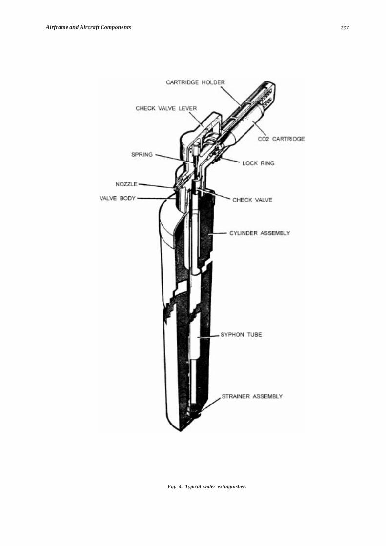
137Airframe and Aircraft Components
Fig. 4. Typical water extinguisher.
138 L.N.V.M. Society Group of Institutes, Palam Extn., Part-1, Sec-7, Dwarka, New Delhi-77
Portable ExtinguishersThe portable extinguishers in common use are of the CO
2 type and the water type. Extinguishers containing
extinguishant B.C.F. are also used in some aircraft. The type of extinguisher installed in a particular location is chosento be appropriate to the nature of the possible fires in the compartment in which it is installed. Extinguishers are locatedin accessible positions and installed in suitable attachment brackets with quick-release metal straps. Brief descriptionsof their construction and operation are given in the following paragraphs for general guidance.
CO2 Extinguishers
A typical extinguisher (Fig.3)., comprises a steel cylinder and an operating head incorporating a pistol-type firingmechanism, check valve assembly and discharge horn which characterises CO
2 extinguishers generally. When the
trigger is pressed, a lock wire and seal are broken and the spindle of the check valve assembly is forced downward,thereby removing the valve from its seat. This allows the extinguishant to flow up the siphon tube, through the centreof a safety disc, to discharge from the discharge horn. Releasing of the trigger alloys the valve to reset and seal off theflow. The purpose of the safety disc is to permit the release of extinguishant in the event of excessive internal pressures.When a safety disc bursts, the trigger of the firing mechanism springs downward and exposes the instruction‘REPLACED DISC’ engraved on the side of the trigger.
Water ExtinguishersA typical extinguisher incorporating an antifreeze agent is shown in Fig.4. It comprises a cylinder and a valve body
which houses a lever operated check valve assembly and a nozzle. A cartridge holder containing a cartridge of CO2 is
secured to the valve body, and, in addition to its main operating function, serves as a hand-grip. When the cartridgeholder is twisted the cartridge is punctured causing the CO
2 to be released into the cylinder, thereby pressurising it.
Depression of the check valve assembly lever moves the valve from its seating at the top of a syphon tube, allowingthe extinguishant to be forced up the tube and to discharge through the nozzle. When the lever is released, the valveis returned to its seating under the action of a spring, and the flow of extinguishant is sealed off.
Some water extinguishers have a plastic head which contains an operating trigger and plunger mechanism, andscrews into a threaded boss on the metallic container. The complete assembly is sealed by a rubber sealing ring. Whenthe trigger is squeezed, the plunger mechanism breaks a seal within the operating head and thereby releases theextinguishant. The discharge is subsequently controlled by maintaining or releasing pressure on the trigger. In somecases, the containers are expendable and scrapped after discharge, and only the operating heads are subject toinspection and overhaul procedures.
Weight And Pressure ChecksThe fully charged weight of an extinguisher should be checked at the periods specified in the approved Maintenance
Schedule, and before installation, to verify that no loss of extinguishant has occurred. The weight, including blankingcaps and washers, but excluding cartridge units, is normally indicated on the container or operating head. For anextinguisher embodying a discharge indicator switch, the weight of the switch cable assembly is also excluded.
The date of weighing and the weight should, where specified, be recorded on record cards made out for each typeof extinguisher, and also on labels for attachment to extinguishers. If the weight of an extinguisher is below the indicatedvalue the extinguisher must be withdrawn from service for recharging.
For extinguishers fitted with pressure gauges, checks must be made to ensure that indicated pressures are withinthe permissible tolerances relevant to the temperature of the extinguishers. The relationship between pressures andtemperatures is normally presented in the form of a graph contained within the appropriate aircraft MaintenanceManuals.
In certain types of portable extinguishers, a check on the contents is facilitated by means of a disc type pressureindicator in the base of the container. If the discharge pressure is below the specified value, the disc can be pushedin by normal thumb pressure.
� � �
139Airframe and Aircraft Components
CHAPTER: 20INSPECTION OF METAL AIRCRAFTAFTER ABNORMAL OCCURRENCES
HEAVY OR OVERWEIGHT LANDINGSAn aircraft landing gear is designed to withstand landing at a particular aircraft weight and vertical descent velocity
(the maximum being 10ft/sec at design landing weight). If either of these parameters is exceeded during a landing, thenit is probable that some damage may be caused to the landing gear or its supporting structure. Over stressing may alsobe caused by landing with drift or landing in an abnormal attitude, e.g. nose or tail wheel striking the runway beforethe main wheels.
Some aircraft are fitted with heavy landing indicators, which give a visual indication that specified ‘g’ forces havebeen exceeded, but in all cases of suspected heavy landings, the flight crew should be consulted for details of aircraftweight, fuel distribution, landing conditions, and whether any noises indicative of structural failure were heard.
The damage which may be expected following a heavy landing would normally be concentrated around the landinggear, its supporting structure in the wings or fuselage, the wing and tailplane attachments and the engine mountings.Secondary damage may be found on the fuselage upper and lower skin and structure, and wing skin and structure,depending on the configuration and loading of the aircraft. On some aircraft it is specified that, it no damage is foundin the primary areas, the secondary areas need not be inspected; but if damage is found in the primary areas, then theinspection must be continued.
Preliminary inspection which should normally be carried out after heavy landing are:-
Landing Geari) Examine tyres for excessive creep, flats, bulges, cuts pressure loss, and excessive growth.ii) Examine wheels and brakes for cracks, other damage, and fluid leaks.iii) Examine axles, struts and stays for distortion and other damage.iv) Check shock struts for fluid leaks, scoring and abnormal extension.v) Examine landing gear attachments for signs of cracks, damage or movement. In some instances this may require
removal of certain bolts in critical locations, for a detailed magnetic crack detection test.vi) Examine structure in the vicinity of the landing gear attachments for signs of cracks, distortion, movement of
rivets or bolts, and fluid leakage.vii) Examine doors and fairings for damage and distortionviii) Jack the aircraft and carry out retraction and nose wheel steering tests in accordance with the approved
Maintenance Manual; check for correct operation of locks and warning lights, clearances in wheel bays, fitof doors, and signs of fluid leaks.
Mainplanesi) Examine the upper and lower skin surfaces for signs of wrinkling, pulled rivets, cracks and movement at skin
joints. Intertial loading on the wing will normally result in wrinkles on the lower surface and cracks or rivetdamage on the upper surface, but stress induced by wing-mounted engines may result in wrinkles on eithersurface.
ii) Check for signs of fuel leaks, and seepage from integral tanks.iii) Examine root end fillets for cracks and signs of movement.iv) Check flying controls for freedom of movement; power controlled systems should be checked with the power
off.v) Check balance weights, powered flying control unit mountings and control surface hinges for cracks, and the
control surfaces for cracks or buckling.vi) Where possible, check the wing spars for distortion and cracks.
Fuselagei) Examine fuselage skin for wrinkling or other damage, particularly at skin joints and adjacent to landing gear
attachments and centre section.ii) Examine pressure bulkheads for distortion and cracks.iii) Examine, for distortion and cracks, the supporting structure for heavy components such as galley modules,
batteries, water tanks, fire extinguishers, auxiliary power units, etc.iv) Check that the inertia switches for the fire extinguishers, emergency lights, etc., have not tripped.v) Check instruments and instrument panels for damage and security.vi) Check ducts and system pipes for damage, security, and fluid leaks.vii) Check fit of access doors, emergency exits, etc., and surrounding areas for distortion and cracks.viii) Check loading and unloading operation of cargo containers, and condition of cargo restraint system.
140 L.N.V.M. Society Group of Institutes, Palam Extn., Part-1, Sec-7, Dwarka, New Delhi-77
Enginesi) Check engine controls for full and free movement.ii) Examine engine mountings and pylons for damage and distortion. Tubular members should be checked for
bow greater than prescribed limits, and cracks at welds. Mounting bolts and attachments should be checkedfor damage and evidence of movement.
iii) On turbine engines check freedom of rotating assemblies, and on piston engines check freedom of rotationwith sparking plugs removed.
iv) Examine engine cowlings for wrinkling and distortion and integrity of fasteners.v) Check for oil, fuel and hydraulic fluid leaks.vi) Where applicable, check the propeller shaft for shock loading in accordance with the procedure in the
Maintenance Manual.
Tail Uniti) Check flying controls for freedom of movement.ii) Examine rudder and elevator hinges for cracks, and control surfaces for cracks and distortion, particularly near
balance weight fittings.iii) Examine tailplane attachments and fairings, screw jacks and mountings, for distortion and signs of movement.
Engine RunsProvided that no major structural distortion has been found, engine runs should be carried out in accordance with
the appropriate Maintenance Manual, in order to establish the satisfactory operation of all systems and controls. Ageneral check for system leaks should be carried out while the engines are running, and on turbine the run-down timeshould be checked.
Inspection of Damaged AreasIf any superficial damage is found during the preliminary inspection, the supporting structure should be examined
for distortion, loose rivets, cracks or other damage, and rigging and symmetry checks should be carried out to ascertainwhether the damage has twisted or warped the main airframe structure. Where flying controls pass through supportingstructure, cable tensions should be checked. On pressurised aircraft a cabin leak rate check should be carried out toascertain whether the sealing of the fuselage is satisfactory and unaffected by the damage.
BURST TYRE INCIDENTSIf a tyre bursts during taxying, take-off or landing, fragments of the tyre may fly off the rotating wheel and cause
damage to parts of the aircraft in line with the wheel disc. Where single wheels are employed, more serious damage mayoccur through the wheel rolling on the paved runway and transmitting shocks to the landing gear leg and supportingstructure. Multiple wheel landing gears will generally be less seriously affected by a single burst type, but the axles,bogies, torque links or steering mechanism may become bowed or strained as a result of the effects of uneven loading.
In most cases the wheel on which the burst occurred will generally be damaged and must be returned for overhaul.In addition, the following inspections should be carried out:-
i) Examine for damage, the wheels and tyres which have not burst.ii) Examine the brake units on the affected leg for damage. On those wheels which are not fitted with fusible plugs,
the tyre burst may have resulted form overheating caused by a binding brake, and when the replacement wheelis fitted attention should be given to the operation of the associated brake including in particular, freedomof rotation of the wheel with brakes released.
iii) Examine the landing gear bay for damage and hydraulic fluid leaks.iv) Examine the affected leg, including pipelines, operating jacks, etc., for damage and hydraulic fluid leaks.v) Inspect the supporting structure and attachments of the affected leg, for cracks, warped panels and loose
rivets. In some instances it may be specified that certain highly stressed bolts in the supporting structure orretraction mechanism bolts removed for non-destructive crack detection tests.
vi) Examine the adjacent fuselage or wing skinning, and landing gear doors, for damage.vi) Examine the adjacent fuselage or wing skinning, and landing gear doors, for damage.vii) Check rear-mounted engines for possible ingestion of debris.
FLIGHT THROUGH SEVERE TURBULENCEIf an aircraft has been flown through conditions of severe turbulence, the severity of the turbulence may be difficult
to assess and report upon, but an indication may be obtained from the accelerometers or fatigue meters fitted to someaircraft. However, these instruments are designed to record steady leads, and force peaks recorded during flight throughturbulence may be exaggerated due to instrument inertia, and should not be taken as actual loads. Generally if readings,exceeding -.5g and +2.5g are recorded on transport aircraft, then some damage may be found. With other types of aircraft(e.g. aerobatic or semi-aerobatic) accelerometers and fatigue meters are seldom fitted, and reported flight throughturbulence should always be investigated.
Severe turbulence may cause excessive vertical or lateral forces on the aircraft structure, and the effects may beincreased by the inertia of heavy components such as engines, fuel tanks, water tanks, and cargo. Damage may beexpected at main assembly points such as the wing-to-fuselage joints, tail-to-fuselage joint, and engine mountings.Damage may also occur in those areas of the wings. Fuselage, tailplane and control surfaces where the greatest bending
141Airframe and Aircraft Components
moment takes place, i.e. part way along their length, and may be indicated by skin wrinkles, pulled rivets or similar faults.An inspection for damage, after a report of flight through severe turbulence, should include the inspections
described for over hot landing.
LIGHTNING STRIKESLightning is a discharge of electricity between highly charged cloud formations, or between a charged cloud and
the ground. If an aircraft is flying, or on the ground in the vicinity of such a cloud formation, the discharge may strikethe aircraft and result in very high voltage and currents passing through the structure. All separate parts of an aircraftare electrically bonded together to conduct a lighting strike away from areas where damage may hazard the aircraft, e.g.fuel tanks or flying controls, and during manufacture special precautions are often taken with non-metallic componentssuch as wing tips, external fuel tanks and nose cones.
Lightning strikes may have two effects on an aircraft; strike damage where the discharge enters the aircraft, andstatic discharge damage subsequent to the strike. Strike damage is generally found at the wing tips, leading edges ofwings and tail unit, and at the fuselage nose, but on some aircraft types other areas may be particularly susceptible,and this information should be obtained from the appropriate Maintenance Manual. Static discharge damage will usuallybe found at wing tips, trailing edges and antennae.Strike damage is usually in the form of small circular holes in the exterior skin, either in clusters or spread out over awide area, and often accompanied by burning or discoloration, blisters on radomes and cracks in glass fibre. Staticdischarge damage is usually in the form of local pitting and burning at trailing edges.
InspectionSince both lightning and turbulence occur in thunderstorms, an inspection for lightning damage will often coincide
with an inspection following reported flight severe turbulence. The areas mentioned above should be examined for signsof strike or static discharge damage, and bonding strips and static discharge wicks should be examined for burning anddisintegration. All control surfaces, including flaps, spoilers and tabs, should be inspected for damage at their hingebearings; unsatisfactory bonding may have allowed static discharge and tracking across the bearings, unsatisfactorybonding may have allowed static discharge and tracking across the bearings, causing burning, break-up or seizure. Acheck for roughness and resistance to movement at each bearing, break in or seizure. A check for roughness andresistance to movement at each bearing, will usually indicate damage at such points. In addition, the followinginspections should be carried out:-
i) Examine engine cowlings and engine for signs of burning or pitting. If a lightning strike is evident, trackingthrough the bearings may have occurred, and some manufacturers recommend that the oil filters and chipdetectors should be examined for signs of contamination; this check should be repeated periodically for aspecified number of running hours after the occurrence.
ii) Examine the fuselage skin and rivets generally, for burning or pitting.iii) If the landing gears was extended when the lightning strike occurred, examine the lower parts of the gear for
static discharge damage. Check for residual magnetism and demagnetize where necessary.
The inspections outlined in above paragraphs should be followed by functional checks of the radio and radarequipment, instruments, compasses, electrical circuit, and flying controls, in accordance with the relevant chapters ofthe approved Maintenance Manual. On some aircraft a bonding resistance check on radomes may also be specified.
DAMAGE FROM JET BLASTConsiderable damage may be caused to an aircraft through the action of another aircraft turning or taxying in the
vicinity. The damage may be caused by blast or impact from debris, and may be particularly severe in the case of lightaircraft.
Flying control surfaces should be inspected for distortion, particularly where they were unlocked and may havebeen driven hard against their stops.
An inspection for impact damage in the form of skin dents and cracked or chipped windscreens or windows, shouldbe made, and the air intakes for engines, heat exchangers, etc., should be examined for debris which may have blowninto them.
With light aircraft, further inspections may be necessary to ensure that no structural damage has been sustained,particularly when the jet blast has been sufficiently strong to move the whole aircraft.
OTHER OCCURRENCESOccurrences not covered in the preceding paragraph or peculiar to a particular aircraft type, may necessitate a special
inspection, and this is often specified in the appropriate Maintenance Manual. Where no specific instructions exist,experience on the type aircraft, combined with a knowledge of the structure and stress paths, will normally enable asatisfactory inspection to be carried out. As an example, if the flap limiting speed has been exceeded, the flaps shouldbe examined for twisting and buckling, the hinge brackets on the wings and flaps should be examined for twisting andbuckling, the hinge brackets on the wings and flaps should be examined for twisting and buckling, the hinge bracketson the wings and flaps should be examined for damage such as cracks and strained attachment rivets and bolts, andthe operating mechanism should be examined for general distortion, bowing, cracks and security. Provided these checksare satisfactory, and operation of the system reveals no evidence of malfunction or excessive e friction, then the aircraftmay be considered airworthy.
142 L.N.V.M. Society Group of Institutes, Palam Extn., Part-1, Sec-7, Dwarka, New Delhi-77
HELICOPTERSThe inspections necessary on helicopters following are checks which are required for the main rotor blades, head
and shaft tail rotor and transmission, following heavy landings or flight through severe turbulence. Inspections arealso outlined below are typical.
HEAVY LANDINGS OR FLIGHT THROUGH SEVERE TURBULENCE
Rear Fuselage Or Tail BoomExamine for evidence of strike damage form the main rotor blades, and if damage is found check for cracks, security
and symmetry.
Main Rotor BladesRemove the rotor blades and examine them for twisting and distortion. Check the surface for cracks, wrinkles, or
other damage, and check the security of the skin attachment rivets or structural bonding. If the main rotor blades arebadly damaged through impact with tail boom or ground, certain components in the transmission may be shock-loaded,and it is sometimes specified that for example, the main rotor shaft, pitch change rods, and main gear box mounting blots,should also be removed for inspection.
Main Rotor HeadDisconnect pitch change rods and dampers, and check that the flapping hinges, and blade sleeves move freely,
without signs of binding or roughness. Examine the rotor head and blade stops for cracks or other damage, and thedampers for signs of fluid leaks. Damage in this area may be an indication of further damage inside the main gearbox.
Tail RotorExamine the blades for damage and security, and the coning stops for evidence of damage. Damage to the tail rotor
blades which is beyond limits, will normally entail either inspection or replacement of the hub, pitch change links, tailrotor gear box and driven shaft.
Rotor OverspeedingThe extent of the inspection will normally depend on the degree of overspeeding. Overspeeding below a specified
limit will usually entail checking the rotor blades for distortion and damage, and the rotor head for cracks and smoothoperation, but, if this limit is exceeded it is usually specified that both the main rotor head and tail rotor head shouldbe removed for overhaul. If damage has occurred to the main rotor blades, the rotor head, shaft, pitch control rods, tailrotor and transmission should also be removed for overhaul, and the gearbox attachments should be inspected fordamage.
� � �
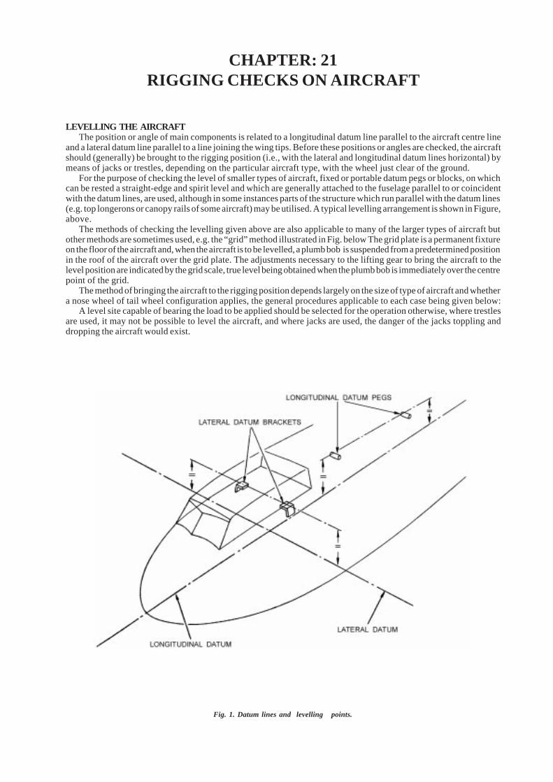
143Airframe and Aircraft Components
CHAPTER: 21RIGGING CHECKS ON AIRCRAFT
LEVELLING THE AIRCRAFTThe position or angle of main components is related to a longitudinal datum line parallel to the aircraft centre line
and a lateral datum line parallel to a line joining the wing tips. Before these positions or angles are checked, the aircraftshould (generally) be brought to the rigging position (i.e., with the lateral and longitudinal datum lines horizontal) bymeans of jacks or trestles, depending on the particular aircraft type, with the wheel just clear of the ground.
For the purpose of checking the level of smaller types of aircraft, fixed or portable datum pegs or blocks, on whichcan be rested a straight-edge and spirit level and which are generally attached to the fuselage parallel to or coincidentwith the datum lines, are used, although in some instances parts of the structure which run parallel with the datum lines(e.g. top longerons or canopy rails of some aircraft) may be utilised. A typical levelling arrangement is shown in Figure,above.
The methods of checking the levelling given above are also applicable to many of the larger types of aircraft butother methods are sometimes used, e.g. the “grid” method illustrated in Fig. below The grid plate is a permanent fixtureon the floor of the aircraft and, when the aircraft is to be levelled, a plumb bob is suspended from a predetermined positionin the roof of the aircraft over the grid plate. The adjustments necessary to the lifting gear to bring the aircraft to thelevel position are indicated by the grid scale, true level being obtained when the plumb bob is immediately over the centrepoint of the grid.
The method of bringing the aircraft to the rigging position depends largely on the size of type of aircraft and whethera nose wheel of tail wheel configuration applies, the general procedures applicable to each case being given below:
A level site capable of bearing the load to be applied should be selected for the operation otherwise, where trestlesare used, it may not be possible to level the aircraft, and where jacks are used, the danger of the jacks toppling anddropping the aircraft would exist.
Fig. 1. Datum lines and levelling points.
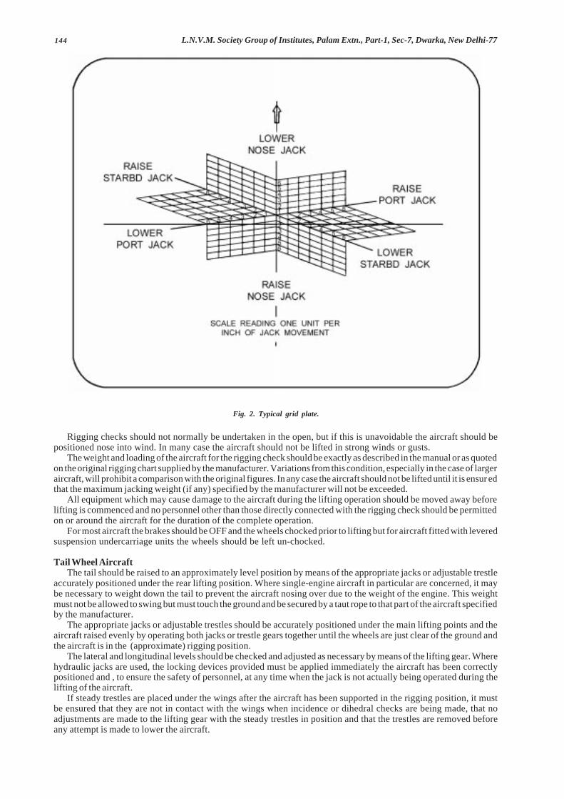
144 L.N.V.M. Society Group of Institutes, Palam Extn., Part-1, Sec-7, Dwarka, New Delhi-77
Rigging checks should not normally be undertaken in the open, but if this is unavoidable the aircraft should bepositioned nose into wind. In many case the aircraft should not be lifted in strong winds or gusts.
The weight and loading of the aircraft for the rigging check should be exactly as described in the manual or as quotedon the original rigging chart supplied by the manufacturer. Variations from this condition, especially in the case of largeraircraft, will prohibit a comparison with the original figures. In any case the aircraft should not be lifted until it is ensuredthat the maximum jacking weight (if any) specified by the manufacturer will not be exceeded.
All equipment which may cause damage to the aircraft during the lifting operation should be moved away beforelifting is commenced and no personnel other than those directly connected with the rigging check should be permittedon or around the aircraft for the duration of the complete operation.
For most aircraft the brakes should be OFF and the wheels chocked prior to lifting but for aircraft fitted with leveredsuspension undercarriage units the wheels should be left un-chocked.
Tail Wheel AircraftThe tail should be raised to an approximately level position by means of the appropriate jacks or adjustable trestle
accurately positioned under the rear lifting position. Where single-engine aircraft in particular are concerned, it maybe necessary to weight down the tail to prevent the aircraft nosing over due to the weight of the engine. This weightmust not be allowed to swing but must touch the ground and be secured by a taut rope to that part of the aircraft specifiedby the manufacturer.
The appropriate jacks or adjustable trestles should be accurately positioned under the main lifting points and theaircraft raised evenly by operating both jacks or trestle gears together until the wheels are just clear of the ground andthe aircraft is in the (approximate) rigging position.
The lateral and longitudinal levels should be checked and adjusted as necessary by means of the lifting gear. Wherehydraulic jacks are used, the locking devices provided must be applied immediately the aircraft has been correctlypositioned and , to ensure the safety of personnel, at any time when the jack is not actually being operated during thelifting of the aircraft.
If steady trestles are placed under the wings after the aircraft has been supported in the rigging position, it mustbe ensured that they are not in contact with the wings when incidence or dihedral checks are being made, that noadjustments are made to the lifting gear with the steady trestles in position and that the trestles are removed beforeany attempt is made to lower the aircraft.
Fig. 2. Typical grid plate.
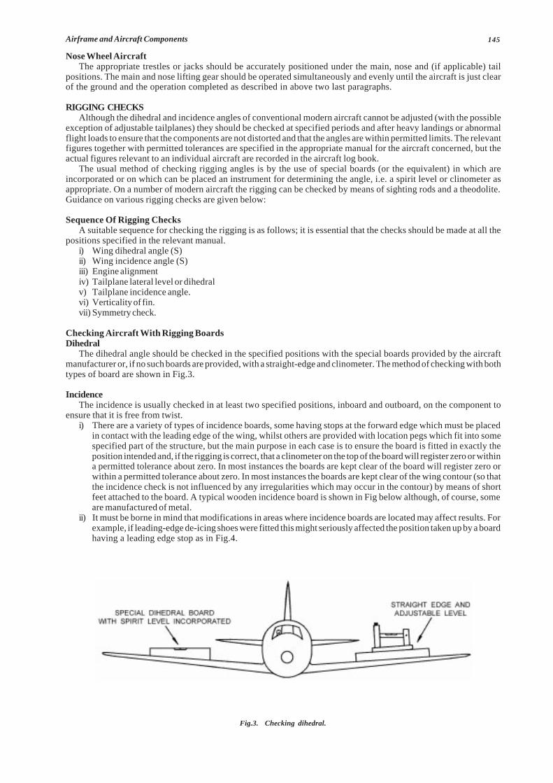
145Airframe and Aircraft Components
Nose Wheel AircraftThe appropriate trestles or jacks should be accurately positioned under the main, nose and (if applicable) tail
positions. The main and nose lifting gear should be operated simultaneously and evenly until the aircraft is just clearof the ground and the operation completed as described in above two last paragraphs.
RIGGING CHECKSAlthough the dihedral and incidence angles of conventional modern aircraft cannot be adjusted (with the possible
exception of adjustable tailplanes) they should be checked at specified periods and after heavy landings or abnormalflight loads to ensure that the components are not distorted and that the angles are within permitted limits. The relevantfigures together with permitted tolerances are specified in the appropriate manual for the aircraft concerned, but theactual figures relevant to an individual aircraft are recorded in the aircraft log book.
The usual method of checking rigging angles is by the use of special boards (or the equivalent) in which areincorporated or on which can be placed an instrument for determining the angle, i.e. a spirit level or clinometer asappropriate. On a number of modern aircraft the rigging can be checked by means of sighting rods and a theodolite.Guidance on various rigging checks are given below:
Sequence Of Rigging ChecksA suitable sequence for checking the rigging is as follows; it is essential that the checks should be made at all the
positions specified in the relevant manual.i) Wing dihedral angle (S)ii) Wing incidence angle (S)iii) Engine alignmentiv) Tailplane lateral level or dihedralv) Tailplane incidence angle.vi) Verticality of fin.vii) Symmetry check.
Checking Aircraft With Rigging BoardsDihedral
The dihedral angle should be checked in the specified positions with the special boards provided by the aircraftmanufacturer or, if no such boards are provided, with a straight-edge and clinometer. The method of checking with bothtypes of board are shown in Fig.3.
IncidenceThe incidence is usually checked in at least two specified positions, inboard and outboard, on the component to
ensure that it is free from twist.i) There are a variety of types of incidence boards, some having stops at the forward edge which must be placed
in contact with the leading edge of the wing, whilst others are provided with location pegs which fit into somespecified part of the structure, but the main purpose in each case is to ensure the board is fitted in exactly theposition intended and, if the rigging is correct, that a clinometer on the top of the board will register zero or withina permitted tolerance about zero. In most instances the boards are kept clear of the board will register zero orwithin a permitted tolerance about zero. In most instances the boards are kept clear of the wing contour (so thatthe incidence check is not influenced by any irregularities which may occur in the contour) by means of shortfeet attached to the board. A typical wooden incidence board is shown in Fig below although, of course, someare manufactured of metal.
ii) It must be borne in mind that modifications in areas where incidence boards are located may affect results. Forexample, if leading-edge de-icing shoes were fitted this might seriously affected the position taken up by a boardhaving a leading edge stop as in Fig.4.
Fig.3. Checking dihedral.
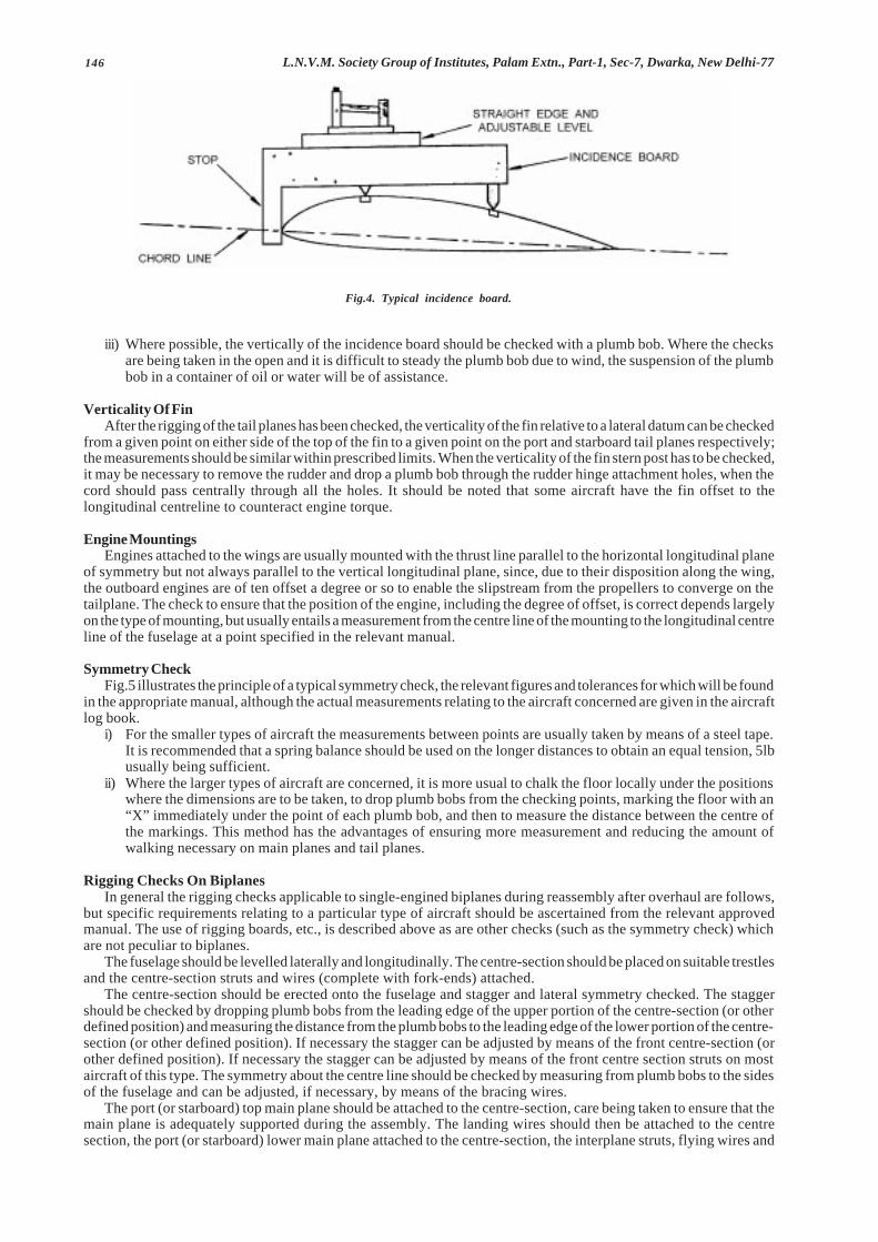
146 L.N.V.M. Society Group of Institutes, Palam Extn., Part-1, Sec-7, Dwarka, New Delhi-77
iii) Where possible, the vertically of the incidence board should be checked with a plumb bob. Where the checksare being taken in the open and it is difficult to steady the plumb bob due to wind, the suspension of the plumbbob in a container of oil or water will be of assistance.
Verticality Of FinAfter the rigging of the tail planes has been checked, the verticality of the fin relative to a lateral datum can be checked
from a given point on either side of the top of the fin to a given point on the port and starboard tail planes respectively;the measurements should be similar within prescribed limits. When the verticality of the fin stern post has to be checked,it may be necessary to remove the rudder and drop a plumb bob through the rudder hinge attachment holes, when thecord should pass centrally through all the holes. It should be noted that some aircraft have the fin offset to thelongitudinal centreline to counteract engine torque.
Engine MountingsEngines attached to the wings are usually mounted with the thrust line parallel to the horizontal longitudinal plane
of symmetry but not always parallel to the vertical longitudinal plane, since, due to their disposition along the wing,the outboard engines are of ten offset a degree or so to enable the slipstream from the propellers to converge on thetailplane. The check to ensure that the position of the engine, including the degree of offset, is correct depends largelyon the type of mounting, but usually entails a measurement from the centre line of the mounting to the longitudinal centreline of the fuselage at a point specified in the relevant manual.
Symmetry CheckFig.5 illustrates the principle of a typical symmetry check, the relevant figures and tolerances for which will be found
in the appropriate manual, although the actual measurements relating to the aircraft concerned are given in the aircraftlog book.
i) For the smaller types of aircraft the measurements between points are usually taken by means of a steel tape.It is recommended that a spring balance should be used on the longer distances to obtain an equal tension, 5lbusually being sufficient.
ii) Where the larger types of aircraft are concerned, it is more usual to chalk the floor locally under the positionswhere the dimensions are to be taken, to drop plumb bobs from the checking points, marking the floor with an“X” immediately under the point of each plumb bob, and then to measure the distance between the centre ofthe markings. This method has the advantages of ensuring more measurement and reducing the amount ofwalking necessary on main planes and tail planes.
Rigging Checks On BiplanesIn general the rigging checks applicable to single-engined biplanes during reassembly after overhaul are follows,
but specific requirements relating to a particular type of aircraft should be ascertained from the relevant approvedmanual. The use of rigging boards, etc., is described above as are other checks (such as the symmetry check) whichare not peculiar to biplanes.
The fuselage should be levelled laterally and longitudinally. The centre-section should be placed on suitable trestlesand the centre-section struts and wires (complete with fork-ends) attached.
The centre-section should be erected onto the fuselage and stagger and lateral symmetry checked. The staggershould be checked by dropping plumb bobs from the leading edge of the upper portion of the centre-section (or otherdefined position) and measuring the distance from the plumb bobs to the leading edge of the lower portion of the centre-section (or other defined position). If necessary the stagger can be adjusted by means of the front centre-section (orother defined position). If necessary the stagger can be adjusted by means of the front centre section struts on mostaircraft of this type. The symmetry about the centre line should be checked by measuring from plumb bobs to the sidesof the fuselage and can be adjusted, if necessary, by means of the bracing wires.
The port (or starboard) top main plane should be attached to the centre-section, care being taken to ensure that themain plane is adequately supported during the assembly. The landing wires should then be attached to the centresection, the port (or starboard) lower main plane attached to the centre-section, the interplane struts, flying wires and
Fig.4. Typical incidence board.
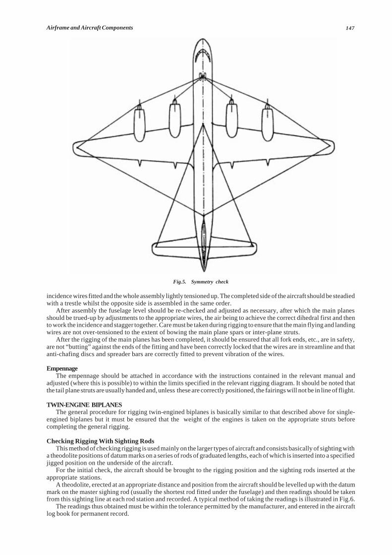
147Airframe and Aircraft Components
incidence wires fitted and the whole assembly lightly tensioned up. The completed side of the aircraft should be steadiedwith a trestle whilst the opposite side is assembled in the same order.
After assembly the fuselage level should be re-checked and adjusted as necessary, after which the main planesshould be trued-up by adjustments to the appropriate wires, the air being to achieve the correct dihedral first and thento work the incidence and stagger together. Care must be taken during rigging to ensure that the main flying and landingwires are not over-tensioned to the extent of bowing the main plane spars or inter-plane struts.
After the rigging of the main planes has been completed, it should be ensured that all fork ends, etc., are in safety,are not “butting” against the ends of the fitting and have been correctly locked that the wires are in streamline and thatanti-chafing discs and spreader bars are correctly fitted to prevent vibration of the wires.
EmpennageThe empennage should be attached in accordance with the instructions contained in the relevant manual and
adjusted (where this is possible) to within the limits specified in the relevant rigging diagram. It should be noted thatthe tail plane struts are usually handed and, unless these are correctly positioned, the fairings will not be in line of flight.
TWIN-ENGINE BIPLANESThe general procedure for rigging twin-engined biplanes is basically similar to that described above for single-
engined biplanes but it must be ensured that the weight of the engines is taken on the appropriate struts beforecompleting the general rigging.
Checking Rigging With Sighting RodsThis method of checking rigging is used mainly on the larger types of aircraft and consists basically of sighting with
a theodolite positions of datum marks on a series of rods of graduated lengths, each of which is inserted into a specifiedjigged position on the underside of the aircraft.
For the initial check, the aircraft should be brought to the rigging position and the sighting rods inserted at theappropriate stations.
A theodolite, erected at an appropriate distance and position from the aircraft should be levelled up with the datummark on the master sighing rod (usually the shortest rod fitted under the fuselage) and then readings should be takenfrom this sighting line at each rod station and recorded. A typical method of taking the readings is illustrated in Fig.6.
The readings thus obtained must be within the tolerance permitted by the manufacturer, and entered in the aircraftlog book for permanent record.
Fig.5. Symmetry check
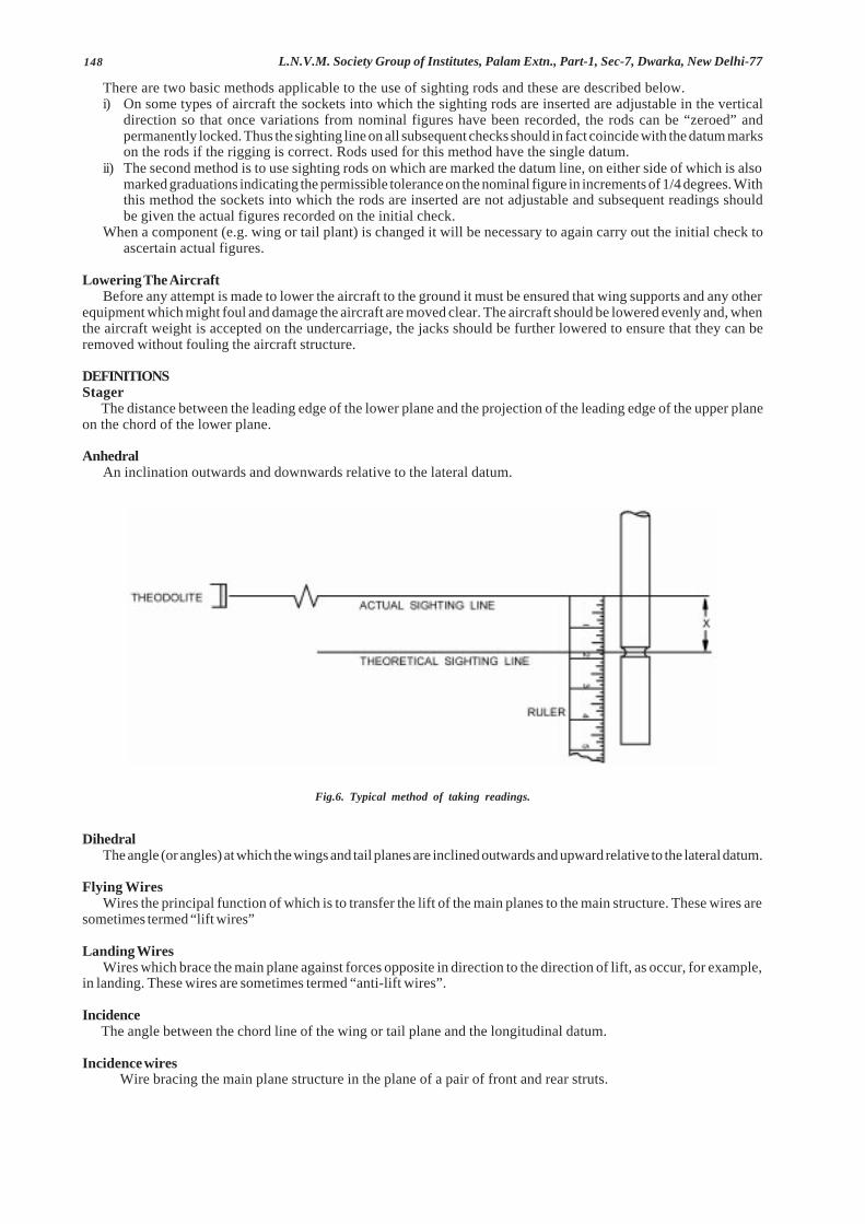
148 L.N.V.M. Society Group of Institutes, Palam Extn., Part-1, Sec-7, Dwarka, New Delhi-77
There are two basic methods applicable to the use of sighting rods and these are described below.i) On some types of aircraft the sockets into which the sighting rods are inserted are adjustable in the vertical
direction so that once variations from nominal figures have been recorded, the rods can be “zeroed” andpermanently locked. Thus the sighting line on all subsequent checks should in fact coincide with the datum markson the rods if the rigging is correct. Rods used for this method have the single datum.
ii) The second method is to use sighting rods on which are marked the datum line, on either side of which is alsomarked graduations indicating the permissible tolerance on the nominal figure in increments of 1/4 degrees. Withthis method the sockets into which the rods are inserted are not adjustable and subsequent readings shouldbe given the actual figures recorded on the initial check.
When a component (e.g. wing or tail plant) is changed it will be necessary to again carry out the initial check toascertain actual figures.
Lowering The AircraftBefore any attempt is made to lower the aircraft to the ground it must be ensured that wing supports and any other
equipment which might foul and damage the aircraft are moved clear. The aircraft should be lowered evenly and, whenthe aircraft weight is accepted on the undercarriage, the jacks should be further lowered to ensure that they can beremoved without fouling the aircraft structure.
DEFINITIONSStager
The distance between the leading edge of the lower plane and the projection of the leading edge of the upper planeon the chord of the lower plane.
AnhedralAn inclination outwards and downwards relative to the lateral datum.
Fig.6. Typical method of taking readings.
DihedralThe angle (or angles) at which the wings and tail planes are inclined outwards and upward relative to the lateral datum.
Flying WiresWires the principal function of which is to transfer the lift of the main planes to the main structure. These wires are
sometimes termed “lift wires”
Landing WiresWires which brace the main plane against forces opposite in direction to the direction of lift, as occur, for example,
in landing. These wires are sometimes termed “anti-lift wires”.
IncidenceThe angle between the chord line of the wing or tail plane and the longitudinal datum.
Incidence wiresWire bracing the main plane structure in the plane of a pair of front and rear struts.
� � �
149Airframe and Aircraft Components
CHAPTER: 22SOLVED QUESTIONS & ANSWERS
FROM AIRCRAFT STRUCTURE PART
1. What are the principal load carrying structures of an airplane?Ans. The principal load carrying sections or components include the fuselage, lifting surfaces, control surfaces,stabilizers, and landing gear. The fuselage is the central aircraft component which has a cockpit or flight deck for thecrew and a section for the passengers and cargo. The lifting surfaces include the wings on airplanes and gliders andthe main rotors of helicopters. Control surfaces include ailerons rudders, elevators, flaps, spoilers, and trim tabs.Stabilizers are used to improve the pitch and yaw stability of the aircraft and the operating terrain.
2. Name five stresses.Ans. The stresses (effects of applied forces) to which structural members are subjected are compression, tension,torsion, bending, and shear.
3. Compare stress and strain.Ans. The term stress is often used interchangeably with word “strain” stress in an internal force of a substance whichopposes or resists deformation. Strain is the deformation of a material or substance.
4. What is meant by stress analysis?Ans. When an airplane is designed, the loads which are likely to be applied to parts or assemblies of the airplane duringoperation are carefully computed and analyzed by engineers. This process is called stress analysis. The performanceof the stress analysis ensures that the airplane will perform according to its approved specifications without dangerof failure.
5. Nomenclature and Definitions.Ans. The definitions given below are provided as a convenient reference for the components of aircraft and some ofthe relationships between components.
AileronOne of a pair of movable control surfaces attached to the trailing edge of each wing tip. The purpose of the aileronsis to control the airplane in roll by creating unequal or opposing lifting forces on opposite sides of the airplane. Largejet airplanes often employ double sets of ailerons a small inboard set for cruise speeds and a larger outboard set forapproach and landing speeds.
Angle of IncidenceThe angle between the chord of an airfoil and the longitudinal axis of an airplane.
Angle Of Stabilizer SettingThe angle of incidence of a vertical or horizontal stabilizer.
Angle Of SweepThe angle between a reference line in a swept or tapered airfoil and a given reference line established for the purpose.For fixed airfoils, the angle is measured between the lateral axis of the airplane and the reference line of the airfoil usuallythe mean chord line.
Anti drag WireA wire in certain kinds of wing structures, running from an inboard point near the trailing edge to an outboard pointnear the leading edge, designed to resist forces acting on the wing in the direction of flight.
Anti lift Wires Same as landing wires.
Balanced Control SurfaceA control surface that is in desired condition of equilibrium about its hinge axis. Such a surface can be balanced foreither static or aerodynamic conditions.
Balancing TabA tab so linked that when the control surface to which it is attached is deflected, the tab is deflected in an oppositedirection, creating a force that aids in moving the larger surface.
150 L.N.V.M. Society Group of Institutes, Palam Extn., Part-1, Sec-7, Dwarka, New Delhi-77
Boom (Also Tailboom)A tubular or truss structure extending aft from the aircraft fuselage. Normally found on helicopters to support the tailrotor and its systems or to support control surfaces on an aircraft having a pusher propeller installation.
BulkheadA vertical structural member that, with other bulkheads often include walls or partial walls which separate fuselagecompartments from one another. Lighter frames or formers are used for support between bulkheads.
CabaneAn arrangement of struts used to support a wing above the fuselage of an airplane.
CanardAn aircraft or aircraft configuration having its horizontal stabilizing and control surfaces in front of the wing or wings.
CantileverA beam or member supported at or near one end only, without external bracing.
Center sectionThe middle or central section of an airplane wing to which the outer wing panels are attached.
Chord LineA straight line connecting the leading edge and the trailing edge of an airfoil.
CockpitOn small aircraft, the area occupied by the pilot and passengers. On cabin airplanes, if the pilot’s compartment isseparated from the rest of the cabin, it is often called the cockpit.
Cockpit CanopyA transparent cover for the cockpit.
Control CablesCables connecting the control levers with the control surfaces.
Control StickA vertical lever by means of which the pilot operates the longitudinal and lateral control surfaces of the airplane. Theelevator is operated by a fore-and-aft movement of the stick, and the ailerons are moved by a sideways movement ofthe stick.
Control SurfaceA movable airfoil or surface, such as an aileron, elevator, rudder vator, flap, trim tab, or rudder, used to control the attitudeor motion of an aircraft in flight.
Control WheelA wheel or semiwheel used in connection with the control column in an airplane. Rotation of the wheel operates theailerons for control about the roll axis. Fore-and-aft movement of the wheel operates the elevators to pitch the airplaneabout the lateral axis.
CowlingA removable cover or housing placed over or around an aircraft component or section, especially an engine.
DecalageThe difference between the angles of incidence for two airfoils on the same airplane. It generally refers to the two wingsof a biplane.
Dihedral AngleThe angle between the aircraft lateral axis and the projection of the wing axis of the airplane. If the tip of the wing ishigher than the root section, the dihedral angle is positive; if lower, the dihedral angle is negative.
Drag StrutAny strut used to resist drag or antidrag forces. In a wing it is a for-and-aft compression member. In landing gear itis a strut that runs diagonally up into the airplane to resist drag forces.
Drag WireA wire in certain kinds of wing structures running from a forward inboard point to an aft outboard point to resist dragforces.
151Airframe and Aircraft Components
ElevatorA movable auxiliary airfoil or control surface designed to control the pitch attitude of the aircraft and the angle of attackof the wing. It controls rotation about the lateral axis.
ElevonsControl surfaces which serve the functions of the elevators and ailerons on all-wing and delta-wing aircraft.
FairingA piece, part, or structure, having a smooth stream lined contour, used to cover a nonstreamlined object or to smootha junction.
FinA vertical stabilizer.
FirewallA fireproof or fire-resistant wall or bulk-head separating an engine from the rest of the aircraft structure to prevent thespreading of a fire from the engine compartment.
FlapA hinged, pivoted, or sliding airfoil or plate, normally located at the trailing edge of a wing, extended or deflecteddownward to increase the lift and / or drag. It is generally used for takeoff or landing.
FrameA vertical structural member which supports the stringers and skin of a wood or metal fuselage and gives the fuselageshape.
FuselageThe main or central structure of a heavier-than-air aircraft, typically elongated and approximately streamlined, whichcarries the crew and passengers and to which the wings are attached.
GapThe distance between the chords of two superposed airfoils.
Horizontal StabilizerA stabilizer mounted horizontally on an airplane affording longitudinal stability and to which elevators are attached.
HornA short lever fastened to a control surface to which an operating cable or rod is attached.
Inspection DoorA small door used especially for inspection of the interior of an airplane.
IntercostalA rib or internal brace inside a box beam spar.
Interplane StrutA strut between two wings or other surfaces.
Jury StrutAn auxiliary strut that braces a main strut or struts.
Landing GearThe microstructure that supports the weight of the airplane on the ground, also called alighting gear.
Landing WireWires or cables that brace the wings against the forces that are opposite to the normal direction of lift. These wiresattach to the upper wire above the fuselage and to the lower wing near the outboard end on a biplane.
Leading EdgeThe foremost or front edge of an airfoil or a propeller blade. The rearmost edge is called the trailing edge.
Lift StrutA structural member attached at one end to some midpoint of a wing or stabilizer and at the other end to the fuselage.This external structural member holds the wing or stabilizer in a fixed position relative to the fuselage and carriesstructural loads between the surface and the fuselage.
152 L.N.V.M. Society Group of Institutes, Palam Extn., Part-1, Sec-7, Dwarka, New Delhi-77
Lift WiresWires or cables that brace the wings against the forces of lift. They are also called flying wires.
LongeronA principal longitudinal (fore-and-aft) member of the framing of an aircraft fuselage, usually continuous across a numberof points of support.
Main RotorThe principal rotating airfoil used to generate lift and support the weight of a rotorcraft. A rotorcraft may have oneor two main rotors. In a helicopter the main rotor generates propulsive thrust along with lift.
Nose WheelA wheel placed ahead of the main landing gear of an aircraft to support the weight of the forward portion of the airframe.
PlatingThe heavy metal skin, often tapered in thickness, used to cover the wings and other parts of larger aircraft.
RudderA hinged or movable airfoil used to control the yawing motion of an aircraft.
Rudder PedalEither one of a pair of cockpit pedals for operating a rudder or other directional-control device.
Rudder VatorA control surface, set at a pronounced dihedral (forming a wide V), that serves as both a rudder and elevator.
Shock AbsorberA device built into the landing gear to reduce the shock during landing or taking off.
SkipA fixed type of landing gear made of tubular and/or flat structures, normally associated with helicopters.
SlatAn auxiliary airfoil contoured to the leading edge of a wing when closed. When open, it forms the slot to improve airflowat high angles of attack.
SlotA fixed opening in the leading edge of an airfoil which is used to direct airflow over the surface at high angles of attackto improve control and lift at these attitudes.
SpanThe maximum distance, measured parallel to the lateral axis, from tip to tip of any surface such as a wing or stabilizer.
SparA primary structural member of a wing, stabilizer, control surface, rotor, or other aerodynamic surface.
SpinnerA fairing of approximately conic or paraboloidal shape, fitted coaxially with the propeller hub and spinning with thepropeller.
SpoilerA device located on the top surface of a wing which can be extended to reduce or “spoil” the lift of the wing. This maybe used to control the aircraft rate of descent, lateral movement (roll), or to increase braking effectiveness on landing.
StabilatorA horizontal control surface that is designed to serve as both a stabilizer and an elevator. It is moved about its hingeline by means of the pilot’s control.
StabilizerA fixed or adjustable airfoil or vane that provides stability for an aircraft.
StaggerWith two or more superposed objects or objects fixed in a row, the advance or the amount of advance of one objectahead of another. The amount of advance of one wing of a biplane ahead of the other, of a compressor blade aheadof another, or of one rotor of tandem-rotor helicopter ahead of the other.
153Airframe and Aircraft Components
Stagger WireOn a biplane, a diagonal wire, usually one of a pair forming an X, running fore and aft between the two wings and helpingto maintain a constant stagger.
StringerA longitudinal structural member installed between fuselage frames and formers to give support and strength to theskin.
StrutA supporting brace that bears compression loads, tension loads, or both, as in a fuselage between the longerons orin a landing gear to transmit the airplane loads.
SweepbackThe backward slant from root to tip of an aerodynamic surface.
TailboomSee Boom.
Tail RotorThe small rotor mounted on a shaft at the tail of a helicopter to counteract the torque of the main rotor and providedirectional control for the helicopter. Sometimes it is referred to as an anti torque rotor.
Tail SkidOn certain older airplanes, a skid attached to the rear part of the airplane on the underside and supporting the tail.
Tail WheelA wheel at the tail of certain airplanes used to support the tail section on the ground. A tail wheel may be steerable,retractable, fixed, castering, etc.
Trailing EdgeThe aft edge of an airfoil surface.
Trim TabA tab attached to the trailing edge of an airfoil, used to aid in control surface operation.
Wing RibA chord wise member used to give the wing its shape and to transmit the load from the surface covering to the spars.
Wing SparA principal span wise member in the structure of a wing.
Wing TipThe outer extremity of a wing.
Q.6. Name three types of fuselages classified according to the method by which stresses are transmitted.Ans. Fuselage is classified in three principal, types depending upon the method by which stresses are transmittedto the structure. The three type according to their classification are : Truss, Semimonocoque and monocoque.
Q.7. What is a load carrying part of a monocoque fuselage.Ans. Skin is the load carrying part of a monocoque fuselage.
Q.8. Describe a truss structure.Ans. A truss is an a assemblage of members forming a rigid framework, which may consist of bars, beams, rods, tubes,wires, etc. The truss-type fuselage may be sub classified as the Pratt truss and the Warren truss. The primary strengthmembers of both Pratt and Warren trusses are the four longerons. As defined previously, the longeron is a principallongitudinal member of the aircraft fuselage. In the truss-type fuselage, lateral bracing is placed at intervals. The lateralstructures may be classed as bulkheads, although this is not strictly true from the technical standpoint : the spacesbetween the bulkheads are called bays.
A Pratt TrussSimilar to the type used in present aircraft with tubular fuselage members is shown in figure. In the original Pratt trussthe longerons were connected with rigid vertical and lateral members called struts, but the diagonal members were madeof strong steel wire and were designed to carry tension only. In the Pratt truss shown in figure, the diagonal membersare rigid and can carry either tension or compression.
154 L.N.V.M. Society Group of Institutes, Palam Extn., Part-1, Sec-7, Dwarka, New Delhi-77
A Warren TrussIs illustrated in figure in this construction, the longerons are connected with only diagonal members. Normally, allmembers in the truss are capable of carrying both tension and compression. When the load is acting in one direction,compression loads are carried by every other member while the alternate members carry the tension loads. When theload is reserved, the members that are carrying tension previously now carry compression and those that were carryingcompression now carry tension.
Q.9. What is the term for the longitudinal (fore-and-aft) structural members of a semimonocoque fuselage?Ans. The longitudinal members of a semimonocoque fuselage are called as stringers, and they serve to stiffen the metalskin and prevent it from bulging or buckling under severe stress.
Q.10. Describe the construction of a typical metal fuselage.Ans. The great majority of fuselages are all-metal and semimonocoque in construction. This applies to small, medium,and large aircraft. The interior structure to which the skin or plating is attached consists of longerons, frames, bulkheads,stringers, gussets, and possibly intercostal members riveted, bolted, or bonded together to form a rigid structure whichshapes the fuselage. The skin or plating is riveted or bonded to the structure to form the complete unit.
Q.11. Why does the skin thickness on a metal fuselage vary at different locations?Ans. Skin thickness on a metal fuselage vary at different location because the load which skin has to carry varies atdifferent places. Places where the skin has to carry more loads there the thickness will be more e.g. the passenger cabinhave thicker skin than the tail section.
Q.12. What is a fail safe feature in aircraft construction?Ans. Many aircraft designs are now incorporating components which are termed “ fail-safe.” These major structuralfittings are made in two parts and joined together by riveting or bonding. Each half of the two structural parts in capableof carrying the full required structural load of the assembly. With this design philosophy, the failure of one of the fittingcomponents will not result in a structural failure of the attachment in flight. In some large aircraft, a fail-safe featureis also incorporated into the metal skin. For example, on a DC - 8, titanium rip-stop doublers are used to reinforce theskin at strategic fuselage frames and at each door and window. In addition, beaded doublers are used in the windowbelt area forward of the front spar.
Q.13. Discuss the construction of fuselages for large jet airplane.Ans. Because of their size, transport aircraft fuselages are commonly constructed by first building sub assemblies oflong panels several feet high. These panels are then joined on a mating jig to form the circular shape of a fuselage. Thefuselage is then assembled by connecting the forward, mid, and aft fuselage sections.
The forward section tapers the cross section of the fuselage to the front of the aircraft. This section has provisionsfor the flight crew stations.
The transport fuselage contains one or more mid-section assemblies. These mid section assemblies are basicallycircular in shape with a constant cross-section size. The mid section contains structures to connect the fuselage tothe wing and may include landing gear attachment points.
The aft section changes the cross-sectional shape of the fuselage into the size and shape necessary to join withthe fuselage after body or tail cone. The after body or tail cone is the point of attachment for the aft flight control surfacesand, depending on the aircraft design, may also incorporate an engine installation area. The fuselage section are joinedto complete the basic assembly of the fuselage.
Q.14. List the principle load-carrying structural components in a light aeroplane wing.Ans. A cantilever wing contains all of its structural components in a light airplane wing are spars, ribs and surfacecoverings.
Q.15. What is the primary structural design difference between a cantilever wing and semi cantilever wing?Ans. A cantilever wing contains all of its structural strength inside the wing structure and requires no external bracing.This type of wing is normally found on high-performance aircraft and on transports. The semi cantilever design obtainsits strength both by internal wing design and external support and by bracing such is comes from struts and wires.This type of wing is usually found on light aircraft designs and relatively slow aircraft designed to carry heavy loads.All wings can be considered to be of semimonocoque construction as the internal structure carries the primary loadsof the wing.
Q.16. Discuss different types of construction for metal ribs in a light airplane wings.Ans. Typical metal ribs are shown in fig. Starting at the top of the illustration the built-up rib is used in conjunctionwith metal spars and is riveted to them. The stamped rib with lightening holes and the stamped rib with a truss-typecross section are used with either metal or wood spars. The rib at the bottom of the picture is stamped in three sectionsand is usually riveted to metal spars.
Q.17. How is a metal wing sealed so it may be used as a fuel tank?Ans. Fuel tanks are included in the basic wing structure so that the wing serves as the fuel tank. This is known asan integral fuel tank design, also referred to as a “wet wing.” The integral tanks are sealed with special compounds
155Airframe and Aircraft Components
applied to fasteners and between components during assembly. Areas of the wings that do not contain fuel are termed“dry bays”.
Q.18. Discuss the construction of a large jet airplane wing. What is the mainframe of a large aircraft wing? Whatis meant by auxiliary structure of a wing?Ans. The main frame of a modern transport wing consists of the spars, ribs, bulkheads, and skin panels with span wisestiffening members. The assembly of the structure may include the use of nonmetallic composite components and thebonding of metal structures as well as the use of conventional metal alloys and fasteners. The structural strength ofthe wing must be sufficient to carry its own weight along with the weight of the fuel in the wings, the weight of enginesattached to the wings, and the forces imposed by the flight controls and landing gear. These stresses vary tremendouslyin direction and in magnitude during the aircraft’s transitions from moving on the ground to flight operations to returningto the ground.
Transport wings consists of two or more main spars with intermediate spars used between the main spars in somedesigns. These intermediate spars assist the main spars in carrying the operational loads. The front and rear sparsprovide the main supporting structure for fittings attaching the fuselage, engine pylons, main landing gear, and flightsurfaces to the wing. Between the spars are located ribs which, depending upon their design, may be used for purposessuch as fuel bulkheads and the support of control surface along with providing the airfoil shape of the wing.
The auxiliary structure of the wing includes the wing tips, leading edge, and trailing edge. The leading edge of thewing incorporates leading-edge ribs, structural reinforcement members, and attachment points for components suchas slats and leading - edge flaps. The trailing edge also incorporates structural members serving similar purposes tothose of the leading edge. The trailing - edge structure normally incorporates an extensive structure to carry and transmitthe loads imposed by the operation of the flight controls such as flaps and ailerons.
The wing internal structures are covered with large metal skin panels which have span wise stringers attached toachieve the desired structural strength of the wings. The leading edge and trailing edge are attached with permanent-type fasteners. The wing tips are removable for inspection and maintenance.
In many transports, the wing is constructed in three or more major assemblies, such as the left-and right - wing panelsand a center-wing section. These sections are joined with permanent fasteners to form a one-piece wing which isattached to the fuselage.
The fittings used to attach the fuselage, engine pylons, main landing gear, and flight control surfaces to the wingare secured with interference-fit and close-tolerance fasteners and are not considered removable except for structuralrepair. An “ interference-fit” fastener is a bolt, pin, or rivet which is slightly larger than the hole in which it is installed.It must be pressed into place, and during this procedure it tends to stretch the metal into which it is installed. The resultis that there can be no “play” or clearance between the fastener and the installation regardless of expansion orcontraction due to temperature changes. The fastener and the fitting essentially become one unit. Fuel tanks areincluded in the basic wing structure so that the wing serves as the fuel tank.
Q.19. What flight control surfaces are generally attached to the wing structure of a large airplane?Ans. Control surfaces generally attached to the wing structure of a large airplane are ailerons, flaps, tabs, leading edgeflaps and starts, spoilers and speed brakes.
Q.20. Describe the construction of a typical stabilizer for a light airplane and what is the purpose of a verticalstabilizer? What is dorsal fin.Ans. The stabilizers and the control surfaces of an airplane are constructed in a manner similar to the wings but ona much smaller scale. They usually include one or more primary members (spars) and ribs attached to the spars. Thevertical stabilizer (fin) may be constructed as a part of the fuselage or may be a separate member that is both adjustableand removable. The tail section of an airplane, including the stabilizers, elevators, and rudder, is commonly called theempennage.
Horizontal StabilizerThe horizontal stabilizer is used to provide longitudinal pitch stability to the aircraft and is usually attached to the aftportion of the fuselage. It may be located above or below the vertical stabilizer or at some midpoint on the verticalstabilizer.
The stabilizer may be constructed of wood, steel tubing, sheet metal, or composites materials. The method ofconstruction is similar to that used for wings, with spars, ribs, stringers, and a surface skin being used.
The horizontal stabilizer may be designed as a fixed surface attached to the tail cone or as a movable surface usedto provide pitch trim.
If the stabilizer is designed to provide pitch trim, it normally is attached to the fuselage with a pivoting hinge as itsrear spar. At the front spar is an attachment for a mechanical or hydraulic actuator which is controlled by the pilot tomove the leading edge of the stabilizer up and down to change the trim of the aircraft.
Vertical StabilizersThe vertical stabilizer for an airplane is the airfoil section forward of the rudder and is used to provide longitudinal (yaw)stability for the aircraft. This unit is commonly called the fin. The construction of the vertical stabilizer is very muchlike that of the horizontal stabilizer, and, as mentioned previously, it may be constructed as an integral part of thefuselage. The rear structural member of the fin is provided with hinges for the support of the rudder. On many aircrafta dorsal fin is installed immediately forward of the vertical stabilizer. The function of the dorsal fin is to improve the
156 L.N.V.M. Society Group of Institutes, Palam Extn., Part-1, Sec-7, Dwarka, New Delhi-77
yaw stability of the aircraft and to provide a streamline fairing between the vertical stabilizer and the fuselage.Some aircraft, especially those equipped with floats of external cargo pods, may also require the addition of a ventral
fin on the bottom of the fuselage in the area below the vertical stabilizer. Some aircraft also require the use of auxiliaryvertical stabilizers, mounted on the horizontal stabilizer.
Q.21. Name the primary and secondary control surfaces of an airplane.Ans. The primary control surfaces of an airplane include the ailerons, rudder, and elevator. Secondary control surfacesinclude tabs, flaps, spoilers, and slats.
Q.22. Discuss the need of a drain holes in the bottom surfaces of ailerons and other control surfaces.Ans. A drain holes in the bottom surfaces of ailerons and other control surfaces is included to prevent water frombecoming trapped inside the structure and causing the control surfaces to be thrown out of balance.
Q.23. Why is the hinge line of an aileron usually set back from the leading edge?Ans. Aileron control systems operated by the pilot through mechanical connections require the use of balancingmechanisms so that the pilot can overcome the air loads imposed on the ailerons during flight. Balancing of the aileronscan be achieved by extending part of the aileron structure ahead of the hinge line and shaping this area so that theairstream strikes the extension and helps to move the surface. This is known as aerodynamic balancing. Another methodwhich may be used is to place a weight ahead of the hinge line to counteract the flight loads. This is known as staticbalancing. Some aircraft may use a combination of these technique.
Q.24. Why are some ailerons rigged to provide differential control?Ans. The geometry of the control system for the ailerons affects the amount that the ailerons move above or belowthe neutral setting. (The neutral setting fairs the ailerons with the wing contour). Some aircraft have their aileronsoperating asymmetrically that is, they move up the same amount that they move down. Other aircraft have the aileronsoperating asymmetrically that is, the upward-moving aileron moves further than the downward-moving aileron. Thisasymmetrical operation is used in some aircraft designs to reduce the amount of rudder pressure required when makingturns. This reduces what is known as “ adverse aileron yaw,” which is caused by the downward-moving aileron creatingan increase in aerodynamic drag, and results in the airplane yawing away from the direction of the desired turn. Aircrafthaving this arrangement are sometimes said to have differential ailerons.
Q.25. Why rudders are balanced both statically and aerodynamically?Ans. Rudders are usually balanced both statically and aerodynamically to provide for greater ease of operation andto eliminate the possibility of flutter. It should be noted that some light-aircraft rudders do not use any balancing method.Different rudders for light aircraft are shown in below.
Q.26. How is aerodynamic balance accomplished an elevator?Ans. It is aerodynamically balanced in manner similar to aileron ref. question 23.
Q.27. Describe Stabilators, ruddervators, and flaperons.Ans. Some aircraft use combination control surfaces which combine the operation of at least two control and/orstabilizer surfaces into one component. By the use of combination surfaces, the construction of the aircraft can besimplified and the desired control response can be achieved. Examples of these types of control surfaces includestabilators, ruddervators, and flaperons.
A stabilator combines the function of a horizontal stabilizer and an elevator. This type of surface is used primarilyon light aircraft designs and on some high-performance military aircraft. The stabilator usually incorporates a staticbalance weight on an arm ahead of the main spar. This weight can project into the aircraft structure or be carried onthe forward portion of the tips of the stabilator. A stabilator is normally equipped with an anti-servo tab which doublesas a trim tab. The anti servo tab moves in the same direction as the control surface is moved to aid the pilot in returningthe trimmed neutral position.
Ruddervators are flight control surfaces which serve the functions of the rudder and elevators. This is accomplishedby mounting the surfaces at an angle above horizontal. When serving as elevators, the surface on each side of thetail move in the same direction, either up or down. When serving as a rudder, the surfaces move in opposite directions,one up and one down. When combined rudder and elevator control movements are made by the pilot, a control mixingmechanism moves each surface the appropriate amount to get the desired elevator and rudder effect.
Flaperons are surfaces which combine the operation of flaps and ailerons. These types of control surfaces are foundon some aircraft designed to operate from short runways. The flaperon allows the area of the wing normally reservedfor the aileron to be lowered and creates a full-span flap. From the lowered position the flaperon can move up or downto provide the desired amount of roll control while still contributing to the overall lift of the wing.
Q.28. Why are tabs usually attached to the trailing edges of flight control surfaces.Ans. Tabs are small secondary flight control surfaces set into the trailing edges of the primary surfaces. These areused to reduce the pilot’s work load required to hold the aircraft in some constant attitude by “loading” the controlsurface in a position to maintain returning a control surface to a neutral or trimmed-center position. Tabs allow theflight crew to reduce or eliminate the pressure that they must apply to the flight controls.
157Airframe and Aircraft Components
Q.29. What is a trim tab?Ans. A fixed trim tab, is normally a piece of sheet metal attached to the trailing edge of a control surface. This fixedtab is adjusted on the ground by bending it in the appropriate direction to eliminate cabin flight control forces for aspecific flight condition. The fixed tab is normally adjusted for zero control forces while in cruising flight. Adjustmentof the tab is a trial-and-error process where the aircraft must be flown and the trim tab adjusted based on the pilot’sreport. The aircraft must then again be flown to see if further adjustment is necessary. Fixed tabs are normally foundon light aircraft and are used to adjust rudders and ailerons.
Controllable trim tabs are found on most aircraft with at least the elevator tab being controlled. These tabs arenormally operated mechanically by a cable and chain system, electrically by a screw jack mechanism or a motor to drivethe cable and chain system, or hydraulically through actuators. When the pilot wishes to change the attitude of theaircraft with the trim system, be activates the trim control system and causes the trim tab to be deflected in the directionopposite to the desired movement of the control surface. When the trim tab is deflected into a airstream, the air triesto push the tab back flush with the control surface. Since the control mechanism prevents the tab from being pushedback flush, the whole control surface is moved.
Controllable trim tabs are adjusted by means of control wheels or cranks in the cockpit, and an indicator is suppliedto denote the position of the trim tab. If the tabs can be operated electrically or hydraulically, they will incorporate someinstrumentation to indicate tab position.
Q.30. What is the purpose of slat.Ans. The use of slats on the leading edge of high-performance wings is a common method of reducing stalling speedand increasing lift at comparatively slow speeds. The slat forms the leading edge of the wing when not extended andcreates a slot at the leading edge when extended. The slot permits air from the high-pressure area under the leadingedge to flow up through the leading edge and to be directed along the top of the wing. This effectively reduces thepossibility of stall at lower speeds. Slats which extend to form slots may be actuated aerodynamically or by mechanicalcontrol.
Q.31. Short note on servo tabs, anti servo tab and control tab.Ans. Servo tabs are used to aid the pilot in the operation of flight controls. When the pilot moves a primary flight control,a servo tab deflects in the proper direction to aid the pilot in moving the control surface. This reduces the force whichthe pilot must supply to the control system to manoeuvre the aircraft.
An anti-servo tab is used to aid the pilot in returning surface, such as a stabilator, to the neutral position and preventit from moving to a full deflection position due to aerodynamic forces. This type of tab has the opposite effect of a servotab. The anti-servo tab often also serves as the pitch trim tab by allowing the pilot to adjust the neutral trim position.
A control tab is used on some transport aircraft as a manual backup to flight controls which are normally operatedhydraulically. When in a manual reversion mode, the pilot can operate the control tabs, and by their tab action theywill cause the flight controls to move in the appropriate direction.
Q.32. What type of landing gear is most commonly employed on aircraft?Ans. Two type of landing gear are most commonly employed on aircraft they are fixed and retractable and it may alsobe classified according to arrangement of the aircraft.
A fixed landing gear is attached to the airframe so that it is held in a fixed position. As it is always in the airstream,this type of landing gear generates a significant amount of aerodynamic drag. This arrangement is normally found onrelatively low speed aircraft and aircraft designed for simplicity of operation.
A retractable landing gear is carried partially or completely inside the airframe structure to reduce drag. Whennecessary for landing, the gear is extended by some mechanism. The gear is retracted into the airframe after takeoff.
An aircraft can have a combination of fixed and retractable landing gear and the wheels are retractable.The basic landing-gear configurations for aircraft operating on land includes conventional, tricycle, quadra cycle,
in line, and skids.
Q.33. What is the usual means for shock absorption in leading edge?Ans. Various methods are used to absorb the force of ground contact upon landing. These methods can be dividedinto two types of “shock-absorbing” processes; the energy-dissipating type and the energy-returning type. Anenergy-dissipating-type landing gear cushions the contact with the ground and changes the energy of the contact intoheat by causing a liquid to flow through a restricted orifice and/or heating air by compression. This heat is then radiatedto the surrounding atmosphere. Examples of this type of landing gear include air-oleo and spring-oleo shock absorbers.
Energy-returning-type landing gear absorbs the shock of the aircraft contacting the ground and then returns theenergy to the aircraft by exerting an upward force on the aircraft after a very short period of time. This type of landinggear includes the use of rigid gear legs, bungee cords, rubber disks, and spring-type landing gear.
In both types of shock-absorbing methods, some of the energy of ground contact is dissipated through thescrubbing of the tires and fricition of motion between components and mounting structures.
� � �

158 L.N.V.M. Society Group of Institutes, Palam Extn., Part-1, Sec-7, Dwarka, New Delhi-77

INDEXA
Access and inspection doors 22Accumulators 33Actuators 34, 50Adjustment 110Aileron 149Ailerons 16
AIR CONDITIONING 53AIR CYCLE SYSYEM 53
Air supplies 83Air Supplies and Distribution 82
AIR SUPPLY 53, 55Aircraft Climb 67Aircraft Descent 68Aircraft structures 1Airflow and Bleed Air 125Anhedral 148Antiicing and deicing systems 81APU Operation and Control 125Auxiliary power unit (APU) 55
AUXILIARY POWER UNITS 122Auxiliary systems 117Auxiliary Wing Flight Surfaces 18Axial Piston Pump 25
BBasic hydraulic systems 37Bogie under carriages 99Brake Control Valve 50Brake Control Valves 29Bromochlorodifluromethane (B.C.F.) 132Bromotrifluromethane (B.T.M.) 132Burst Tyre Incidents 140
CCabin Altitude 65
CABLE ASSEMBLY 111CABLE CONNECTORS 111
Cable guides 112Carbon dioxide (CO2) 132Castoring 98Checking Aircraft With Rigging Boards 145Checking Rigging With Sighting Rods 147Chemical Oxygen Generator Systems 76Climb 71Closed System 37CO
2 Extinguishers 138
Cold air units 61, 63Combustion heaters 60, 63Combustion heating 53Components 46, 76Components and application of systems 81Compressors 46Compressors and blowers 60, 62Compressors or blowers 55Construction 90, 104, 106, 107Continuous Flow Oxygen Systems 75Control surface snubbers 115Control surface snubbers and locking devices 115Control systems 111Control Valves 50Control-Surface indicating Systems 120Controls and Indicators 44, 82
COOLING 53, 55Cowling 12Cruise 68, 71Cut-Out Valves 27
DDamage From Jet Blast 141Damping 98De-icer Boots 82Definitions 148Dehydrator 48Descent 71Dihedral 145, 148Diluter Demand System 76Directional Flow Valves 134
DISC BRAKES 106Discharge Indicators 80, 134Discharge Valves 71
DISTRIBUTION 59Distribution systems 62, 64
DRUM BRAKES 105Dry Chemical 132
DUCTING 83
EElectrical anti-icing system 86Electrical Indicators 134Electrical Retraction System 95Electrically Operated Control Valve 50Electrically-operated Selectors 32Electromagnetic control 55Electronic Pressurisation Control 70Electronic System 108Elevators 18Emergency Controls 74Emergency Extension 96Emergency Operation 69, 71Empennage 13, 147Engine bleed air system 55Engine exhaust heaters 61Engine exhaust heating 53, 63Engine Mountings 146
ENGINE RUNNING PRECAUTIONS 131Engine Runs 140Engines 140External control surface locks 115Extinguishers 134
FFilters 35, 79Filters and Air Driers 74
FIRE EXTINGUISHING EQUIPMENT 132FIRE-GENERAL PRECAUTIONS 128
Fixed Landing Gear 90Fixed Volume Pumps 25Fixed-wing aircraft 2Flaps 20Flexible Tank 101Flight control surfaces 14
FLIGHT CONTROL SYSTEM HARDWARE,MECHANICAL LINKAGE 111Flight Through Severe Turbulence 140
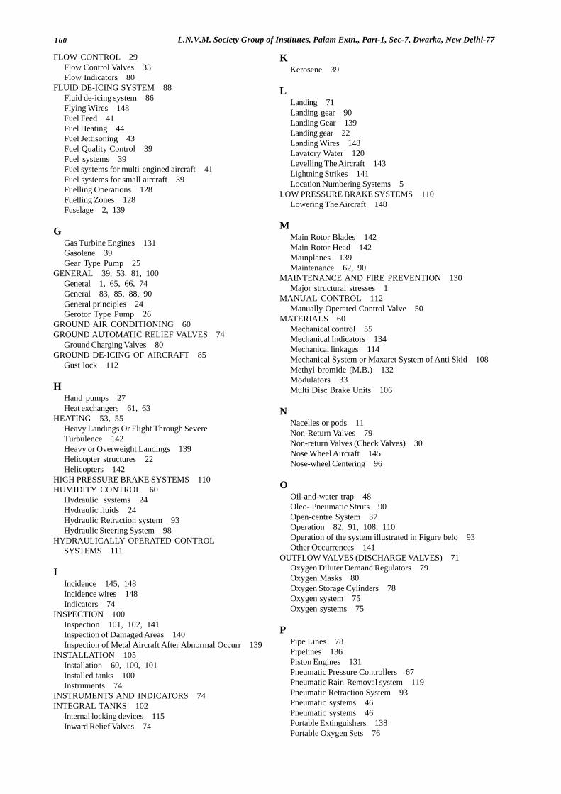
160 L.N.V.M. Society Group of Institutes, Palam Extn., Part-1, Sec-7, Dwarka, New Delhi-77
FLOW CONTROL 29Flow Control Valves 33Flow Indicators 80
FLUID DE-ICING SYSTEM 88Fluid de-icing system 86Flying Wires 148Fuel Feed 41Fuel Heating 44Fuel Jettisoning 43Fuel Quality Control 39Fuel systems 39Fuel systems for multi-engined aircraft 41Fuel systems for small aircraft 39Fuelling Operations 128Fuelling Zones 128Fuselage 2, 139
GGas Turbine Engines 131Gasolene 39Gear Type Pump 25
GENERAL 39, 53, 81, 100General 1, 65, 66, 74General 83, 85, 88, 90General principles 24Gerotor Type Pump 26
GROUND AIR CONDITIONING 60GROUND AUTOMATIC RELIEF VALVES 74
Ground Charging Valves 80GROUND DE-ICING OF AIRCRAFT 85
Gust lock 112
HHand pumps 27Heat exchangers 61, 63
HEATING 53, 55Heavy Landings Or Flight Through SevereTurbulence 142Heavy or Overweight Landings 139Helicopter structures 22Helicopters 142
HIGH PRESSURE BRAKE SYSTEMS 110HUMIDITY CONTROL 60
Hydraulic systems 24Hydraulic fluids 24Hydraulic Retraction system 93Hydraulic Steering System 98
HYDRAULICALLY OPERATED CONTROLSYSTEMS 111
IIncidence 145, 148Incidence wires 148Indicators 74
INSPECTION 100Inspection 101, 102, 141Inspection of Damaged Areas 140Inspection of Metal Aircraft After Abnormal Occurr 139
INSTALLATION 105Installation 60, 100, 101Installed tanks 100Instruments 74
INSTRUMENTS AND INDICATORS 74INTEGRAL TANKS 102
Internal locking devices 115Inward Relief Valves 74
KKerosene 39
LLanding 71Landing gear 90Landing Gear 139Landing gear 22Landing Wires 148Lavatory Water 120Levelling The Aircraft 143Lightning Strikes 141Location Numbering Systems 5
LOW PRESSURE BRAKE SYSTEMS 110Lowering The Aircraft 148
MMain Rotor Blades 142Main Rotor Head 142Mainplanes 139Maintenance 62, 90
MAINTENANCE AND FIRE PREVENTION 130Major structural stresses 1
MANUAL CONTROL 112Manually Operated Control Valve 50
MATERIALS 60Mechanical control 55Mechanical Indicators 134Mechanical linkages 114Mechanical System or Maxaret System of Anti Skid 108Methyl bromide (M.B.) 132Modulators 33Multi Disc Brake Units 106
NNacelles or pods 11Non-Return Valves 79Non-return Valves (Check Valves) 30Nose Wheel Aircraft 145Nose-wheel Centering 96
OOil-and-water trap 48Oleo- Pneumatic Struts 90Open-centre System 37Operation 82, 91, 108, 110Operation of the system illustrated in Figure belo 93Other Occurrences 141
OUTFLOW VALVES (DISCHARGE VALVES) 71Oxygen Diluter Demand Regulators 79Oxygen Masks 80Oxygen Storage Cylinders 78Oxygen system 75Oxygen systems 75
PPipe Lines 78Pipelines 136Piston Engines 131Pneumatic Pressure Controllers 67Pneumatic Rain-Removal system 119Pneumatic Retraction System 93Pneumatic systems 46Pneumatic systems 46Portable Extinguishers 138Portable Oxygen Sets 76
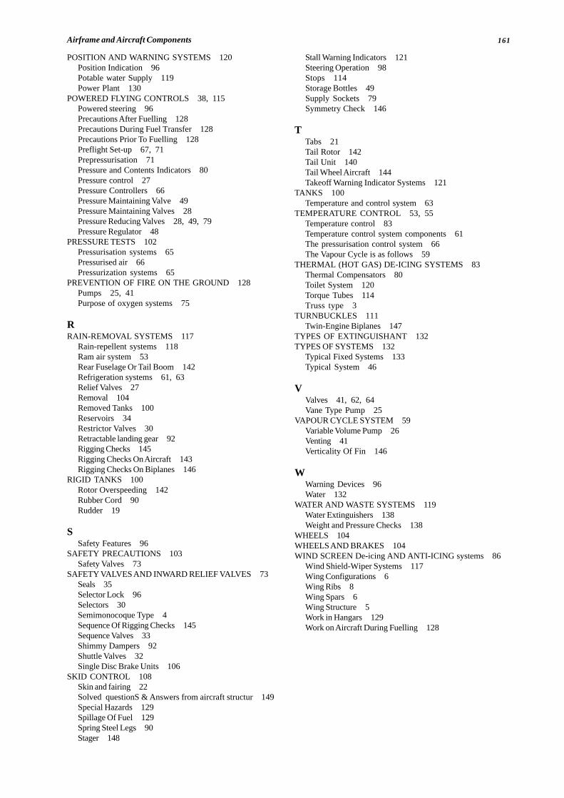
161Airframe and Aircraft Components
POSITION AND WARNING SYSTEMS 120Position Indication 96Potable water Supply 119Power Plant 130
POWERED FLYING CONTROLS 38, 115Powered steering 96Precautions After Fuelling 128Precautions During Fuel Transfer 128Precautions Prior To Fuelling 128Preflight Set-up 67, 71Prepressurisation 71Pressure and Contents Indicators 80Pressure control 27Pressure Controllers 66Pressure Maintaining Valve 49Pressure Maintaining Valves 28Pressure Reducing Valves 28, 49, 79Pressure Regulator 48
PRESSURE TESTS 102Pressurisation systems 65Pressurised air 66Pressurization systems 65
PREVENTION OF FIRE ON THE GROUND 128Pumps 25, 41Purpose of oxygen systems 75
RRAIN-REMOVAL SYSTEMS 117
Rain-repellent systems 118Ram air system 53Rear Fuselage Or Tail Boom 142Refrigeration systems 61, 63Relief Valves 27Removal 104Removed Tanks 100Reservoirs 34Restrictor Valves 30Retractable landing gear 92Rigging Checks 145Rigging Checks On Aircraft 143Rigging Checks On Biplanes 146
RIGID TANKS 100Rotor Overspeeding 142Rubber Cord 90Rudder 19
SSafety Features 96
SAFETY PRECAUTIONS 103Safety Valves 73
SAFETY VALVES AND INWARD RELIEF VALVES 73Seals 35Selector Lock 96Selectors 30Semimonocoque Type 4Sequence Of Rigging Checks 145Sequence Valves 33Shimmy Dampers 92Shuttle Valves 32Single Disc Brake Units 106
SKID CONTROL 108Skin and fairing 22Solved questionS & Answers from aircraft structur 149Special Hazards 129Spillage Of Fuel 129Spring Steel Legs 90Stager 148
Stall Warning Indicators 121Steering Operation 98Stops 114Storage Bottles 49Supply Sockets 79Symmetry Check 146
TTabs 21Tail Rotor 142Tail Unit 140Tail Wheel Aircraft 144Takeoff Warning Indicator Systems 121
TANKS 100Temperature and control system 63
TEMPERATURE CONTROL 53, 55Temperature control 83Temperature control system components 61The pressurisation control system 66The Vapour Cycle is as follows 59
THERMAL (HOT GAS) DE-ICING SYSTEMS 83Thermal Compensators 80Toilet System 120Torque Tubes 114Truss type 3
TURNBUCKLES 111Twin-Engine Biplanes 147
TYPES OF EXTINGUISHANT 132TYPES OF SYSTEMS 132
Typical Fixed Systems 133Typical System 46
VValves 41, 62, 64Vane Type Pump 25
VAPOUR CYCLE SYSTEM 59Variable Volume Pump 26Venting 41Verticality Of Fin 146
WWarning Devices 96Water 132
WATER AND WASTE SYSTEMS 119Water Extinguishers 138Weight and Pressure Checks 138
WHEELS 104WHEELS AND BRAKES 104WIND SCREEN De-icing AND ANTI-ICING systems 86
Wind Shield-Wiper Systems 117Wing Configurations 6Wing Ribs 8Wing Spars 6Wing Structure 5Work in Hangars 129Work on Aircraft During Fuelling 128