Airflow Resistance of Loose-Fill Mineral Fiber Insulations ... Resistance of Loose-Fill Mineral...
106
Airflow Resistance of Loose-Fill Mineral Fiber Insulations in Retrofit Applications Building America Report - 1408 November 2014 Joseph Lstiburek, Christopher Schumacher and M. J. Fox Abstract: building science.com © 2014 Building Science Press All rights of reproduction in any form reserved. This report documents airflow resistance test results for dense-pack retrofit applications using mineral fiber insulation (MFI) materials (i.e., glass fiber and stone wool). The test results are compared to previous airflow resistance tests for dense-pack retrofit applications using 10 different cellulose fiber insulation (CFI) materials.
Transcript of Airflow Resistance of Loose-Fill Mineral Fiber Insulations ... Resistance of Loose-Fill Mineral...
Airflow Resistance ofLoose-Fill Mineral FiberInsulations in RetrofitApplicationsBuilding America Report - 1408November 2014Joseph Lstiburek, Christopher Schumacher and M. J. Fox
Abstract:
building science.com© 2014 Building Science Press All rights of reproduction in any form reserved.
This report documents airflow resistance test results for dense-pack retrofit applications using mineral fiber insulation (MFI) materials (i.e., glass fiber and stone wool). The test results are compared to previous airflow resistance tests for dense-pack retrofit applications using 10 different cellulose fiber insulation (CFI) materials.
Airflow Resistance of Loose-Fill Mineral Fiber Insulations in Retrofit Applications C.J. Schumacher and M.J. Fox Building Science Laboratories J. Lstiburek Building Science Corporation November 2014

NOTICE
This report was prepared as an account of work sponsored by an agency of the United States government. Neither the United States government nor any agency thereof, nor any of their employees, subcontractors, or affiliated partners makes any warranty, express or implied, or assumes any legal liability or responsibility for the accuracy, completeness, or usefulness of any information, apparatus, product, or process disclosed, or represents that its use would not infringe privately owned rights. Reference herein to any specific commercial product, process, or service by trade name, trademark, manufacturer, or otherwise does not necessarily constitute or imply its endorsement, recommendation, or favoring by the United States government or any agency thereof. The views and opinions of authors expressed herein do not necessarily state or reflect those of the United States government or any agency thereof.
Available electronically at http://www.osti.gov/bridge
Available for a processing fee to U.S. Department of Energy and its contractors, in paper, from:
U.S. Department of Energy Office of Scientific and Technical Information P.O. Box 62 Oak Ridge, TN 37831-0062 phone: 865.576.8401 fax: 865.576.5728 email: mailto:[email protected]
Available for sale to the public, in paper, from:
U.S. Department of Commerce National Technical Information Service 5285 Port Royal Road Springfield, VA 22161 phone: 800.553.6847 fax: 703.605.6900 email: [email protected] online ordering: http://www.ntis.gov/ordering.htm
iii
Airflow Resistance of Loose-Fill Mineral Fiber Insulations in Retrofit Applications
Prepared for: The National Renewable Energy Laboratory
On behalf of the U.S. Department of Energy’s Building America Program Office of Energy Efficiency and Renewable Energy
15013 Denver West Parkway Golden, CO 80401
NREL Contract No. DE-AC36-08GO28308
Prepared by:
C.J. Schumacher and M.J. Fox Building Science Laboratories
167 Lexington Crt., Unit5 Waterloo, ON, Canada
and
J. Lstiburek
Building Science Corporation 3 Lan Drive, Suite 102 Westford, MA 01886
NREL Technical Monitor: Stacey Rothgeb
Prepared under Subcontract No. KNDJ-0-40337-05
November 2014
iv
The work presented in this report does not represent performance of any product relative to regulated minimum efficiency requirements. The laboratory and/or field sites used for this work are not certified rating test facilities. The conditions and methods under which products were characterized for this work differ from standard rating conditions, as described. Because the methods and conditions differ, the reported results are not comparable to rated product performance and should only be used to estimate performance under the measured conditions.
v
Contents List of Figures............................................................................................................................................vi List of Tables .............................................................................................................................................vi Definitions .................................................................................................................................................vii Executive Summary ................................................................................................................................viii 1 Introduction and Background.............................................................................................................1
1.1 Introduction ......................................................................................................................................1 1.2 Background.......................................................................................................................................1 1.3 Scope of This Work..........................................................................................................................1 1.4 Material Sample Identification and Collection.................................................................................1
2 Experimental Apparatus and Method.................................................................................................3 2.1 Test Wall Assembly..........................................................................................................................3 2.2 Fiber Moving Machine .....................................................................................................................4 2.3 Manufacturer-Recommended Installation Methods and Densities ..................................................5 2.4 Installation Methods and Densities for Test Wall Specimens ..........................................................6 2.5 Other Experimental Methods............................................................................................................7
3 Results and Discussion.......................................................................................................................8 3.1 Test Program.....................................................................................................................................8 3.2 General Airflow Test Results ...........................................................................................................8
3.2.1 Long- and Short-Path Airflow Test Results ........................................................................8 3.2.2 Flow Regime and Pressure Range .......................................................................................9
3.3 Influence of Material and Installation Method ...............................................................................10 3.3.1 Material O..........................................................................................................................10 3.3.2 Material P ..........................................................................................................................11 3.3.3 Material Q..........................................................................................................................12 3.3.4 Material R ..........................................................................................................................13 3.3.5 Installation Methods ..........................................................................................................14
4 Conclusions and Recommendations ...............................................................................................16 Appendix A: Loose-Fill Fiberglass Insulation Products for Dense-Pack Retrofit Applications .......18 Appendix B: Loose-Fill Stone Wool Insulation Products (Not Intended for Dense-Pack Retrofit
Applications) ......................................................................................................................................19 Appendix C: Example of Dense-Packing Instructions From a Cellulose Insulation Manufacturer ..20

vi
List of Figures Figure 1. Schematic of airflow paths through test wall assembly.........................................................3 Figure 2. InsulMaxx 2000 all fiber machine (left) with double agitators (right) ....................................4 Figure 3. Flow exponents for all MFI tests ...............................................................................................9 Figure 4. Flow exponents for previous CFI tests ..................................................................................10 Figure 5. Material O: long-path airflow rest results versus installed density and installation method11 Figure 6. Material P: long-path airflow rest results versus installed density and installation method12 Figure 7. Material Q: long-path airflow rest results versus installed density and installation method13 Figure 8. Material R: long-path airflow rest results versus installed density and installation method14
Unless otherwise indicated, all figures were created by Building Science Laboratories. List of Tables Table 1. Survey of Dense-Pack and Retrofit Information for Loose-Fill Fiberglass Products ............3 Table 2. Survey of Machine and Hose Recommendations for Dense-Pack and Retrofit Applications
Using Loose-Fill Fiberglass Products................................................................................................4 Table 3. Survey of Recommended Dense-Pack and Retrofit Techniques for Loose-Fill Fiberglass
Products................................................................................................................................................5 Table 4. Summary of Mineral Fiber Test Results With Comparison to Previous Cellulose Tests......8
Unless otherwise indicated, all tables were created by Building Science Laboratories.

vii
Definitions
BPI Building Performance Institute
CFI Cellulose fiber insulation
cfm Cubic feet per minute
ft2 Square foot
ft3 Cubic foot
ID Inside diameter
MFI Mineral fiber insulation
pcf Pounds per cubic foot
psi Pounds per square inch
scfh Standard cubic feet per hour
viii
Executive Summary
In 2011 Building Science Corporation, working under the Building America Program, completed research work to support the development of standards for testing the airflow resistance of insulation materials used in dense-pack retrofit applications. Building America Report 1109, High Impact Project: Support of Standards Development – Dense-pack Airflow Resistance, Final Research Report, provides a detailed summary of the research program, including a summary of airflow resistance test results for 10 cellulose fiber insulation materials. Recently mineral fiber insulation (MFI) materials (glass fiber, stone wool, etc.) have also been developed and/or suggested for dense-pack retrofit applications. Testing is needed to support the inclusion of MFI in new dense-pack air resistance standards.
This report expands on Building America Report 1109 by applying the experimental apparatus and test method to dense-pack retrofit applications using MFI materials. Three fiberglass insulation materials and one stone wool insulation material were tested, and the results compared to the cellulose results from the previous study. Test wall specimens were prepared to cover densities in the range of roughly 1.8–2.5 pcf. Three installation methods were tested, based on a survey of installation instructions provided by a sample of five fiberglass manufacturers: (1) bottom fill, using an insertion tube installed up through a hole at approximately 24 in. above the bottom plate; (2) top fill, using an insertion tube installed down through a hole at approximately 6 in. below the top plates; and (3) 2-in. nozzle, installed through two or three holes (e.g., at holes approximately 24 in., 72 in., and 90 in. above the bottom plate).
Airflow resistance varied significantly between loose-fill fiberglass products, even though all the compared products are marketed and supported for use in dense-pack retrofit applications. When these fiberglass products were installed at approximately 2.2 pcf, the variance was 0.33–1.73 cfm50/ft2. The distribution of the installed material and thus, the airflow resistance also depend on installation method.
Two of the three loose-fill fiberglass products tested (installed at approximately 2.3 pcf) produced long-path flow rates of 0.28 and 0.42 cfm50/ft2 and short-path airflow rates of 0.76 and 1.1 cfm50/ft2. These are comparable to the cellulose dense-pack retrofits benchmarks of 0.33 and 1.0 cfm50/ft2 for the long- and short-path airflow rates, respectively (cellulose fiber insulation installed at 3.5 pcf as required by Building Performance Institute). However, the fiberglass test walls were prepared using the 2-in. nozzle installation method, not the insertion tube methods recommended as best practice for retrofit applications. These results indicate that there is potential for dense-pack applications of MFI, but that more work needs to be done to develop appropriate standards for real-world installation needs. In particular, further testing should be conducted to establish recommended install densities for insertion tube installation methods.
None of the stone wool manufacturers support dense-pack retrofit applications using their products. As a result, only one loose-fill stone wool insulation product was collected for testing. The stone wool fibers and nodules were too large to successfully install using either of the insertion tube techniques. Loose-fill stone wool is not recommended for dense-pack retrofit applications.

1
1 Introduction and Background
1.1 Introduction This report documents airflow resistance test results for dense-pack retrofit applications using mineral fiber insulation (MFI) materials (i.e., glass fiber and stone wool). The test results are compared to previous airflow resistance tests for dense-pack retrofit applications using 10 different cellulose fiber insulation (CFI) materials.
1.2 Background In the early 1980s researchers acknowledged and studied the airflow resistance of dense-pack CFI in materials in retrofit applications (EDU 1986). In 2011 Building Science Corporation, working under the Building America Program, completed research work to support the development of standards for testing the airflow resistance of insulation materials used in dense-pack retrofit applications. Building America Report 1109, High Impact Project: Support of Standards Development – Dense-pack Airflow Resistance, Final Research Report, provides a detailed summary of the research program, including the test apparatus and method that were developed (Schumacher 2011). The same report also provides a summary of airflow resistance test results for 10 CFI materials.
More recently MFI materials (glass fiber, stone wool, etc.) have been developed and/or suggested for dense-pack retrofit applications. Research is needed to develop standards for airflow resistance for these new materials. More specifically, testing is needed to support the development of two new standards by the Building Performance Institute (BPI): BPI-102, which will set requirements for the airflow resistance of insulation used in retrofit cavity (dense-pack) installations, and BPI-103, which will define acceptable test methods to measure the airflow resistance of insulation materials used in dense-pack applications.
1.3 Scope of This Work This report documents airflow resistance test results for three fiberglass insulation materials and one stone wool insulation material.
1.4 Material Sample Identification and Collection Suitable mineral insulation materials were identified through discussion with weatherization industry practitioners, a review of literature from trade publications and online sources, and through discussion with a manufacturer experts’ panel from the North American Insulation Manufacturers Association.
To begin sample selection, five fiberglass insulation materials were identified as intended for and/or used in retrofit wall applications:
• Certainteed’s Optima • Guardian’s CWI Plus
• Johns Manville’s Spider • Knauf’s EcoFill-WX
• Owens Corning’s ProPink L77.
2
We collected six or more sample bags of each fiberglass retrofit product from the respective manufacturers. Appendix A includes manufacturer’s literature for each of the products. Three fiberglass products were randomly selected from the five products collected.
Four stone wool insulation manufacturers produce granular/loose-fill products in North America; however, none of these are intended for or (to the best of our knowledge) used in retrofit wall applications:
• Amerrock’s RockWool Premium Plus • Rolan’s Fibra Mineral Nodular
• Roxul’s Rockfill • Thermafiber’s Spray Wool (one of many Granulated Products).
The stone wool insulation manufacturers were less interested in providing samples, emphasizing that their products were not developed for or supported if used in dense-pack retrofits in residential applications. We were able to collect sample bags from only one of the stone wool insulation manufacturers. To maintain anonymity we will not identify the stone wool sample that we were able to collect and test. Appendix B includes manufacturer’s literature for each of the products.

3
2 Experimental Apparatus and Method
The dense-pack mineral fiber tests were performed using the same apparatus and method that were developed for the dense-pack cellulose fiber tests described by Schumacher (2011). The calibration box, electronic scale, test wall assembly, wall balance, and load cell were the same as those used for the cellulose testing in 2011. Only the fiber moving machine and installation methods were changed.
2.1 Test Wall Assembly Figure 1 shows the test wall assembly and the two flow paths that are evaluated during testing: the short- and long-flow paths. A fan depressurizes the wall assembly so air is drawn in through the air inlet holes in the back panel. The top and bottom inlet holes are used for long path tests; the upper and lower inlet holes are used for short-path tests. The air travels through the dense-packed insulation and out of the wall assembly at the air outlet slot that is located at mid-height on the front panel. The outlet air is collected in a manifold and drawn through a series of flow measurement devices before traveling through the fan and being expelled to the laboratory. This arrangement maximizes the uniformity of airflow, pressures, and temperatures.
A background leakage test is conducted with the top, bottom, upper and lower inlet holes sealed. The top and bottom holes are opened to produce two 45 ¼-in. long-flow paths. The top and bottom holes are then resealed and the upper and lower holes are opened to produce two 16-in. short-flow paths.
Airflow rates are reported in cfm50/ft2 where the area is perpendicular to the flow path. Each test involves flow paths up through three stud spaces and down through three stud spaces so the total flow area is 6 × (3.5 × 14.5 in.) = 304.5 in.2.
Figure 1. Schematic of airflow paths through test wall assembly
4
The installed density is measured with an uncertainty of ± 1% or ± 0.035 pcf. Air pressures are measured using an auto-zeroing digital manometer having a measurement accuracy of ± 1% of reading. Flow rates are measured using rotometers having uncertainty of ± 2% of reading and capable of measuring flow rates down to 5 ± –0.6 scfh.
Schumacher (2011) provides more detailed explanation of the apparatus, test method, and uncertainty.
2.2 Fiber Moving Machine A Krendl Model 450A All-Fiber Machine was used to prepare the cellulose fiber test wall specimens that Schumacher (2011) described. Several fiberglass test wall specimens had been prepared using this machine in 2011; however, the Krendl 450A did not have appropriate mixing paddles and shredders to properly condition the fiberglass material for dense-pack applications.
For the purposes of the mineral fiber dense-pack tests we sought to identify and secure a single machine that could be used for all planned tests. Members of a manufacturer experts’ panel from the North American Insulation Manufacturers Association were approached for input, and all agreed that the following small (i.e., portable, not truck-mount) machines were appropriate for dense-packing fiberglass insulation:
• Accu1 9100 series • Intec Force 3
• Krendl Model 425 or 475 • Spray Insulation Components InsulMaxx 2000 or 4000.
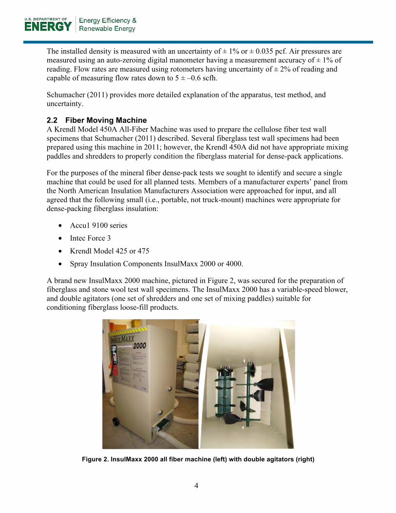
A brand new InsulMaxx 2000 machine, pictured in Figure 2, was secured for the preparation of fiberglass and stone wool test wall specimens. The InsulMaxx 2000 has a variable-speed blower, and double agitators (one set of shredders and one set of mixing paddles) suitable for conditioning fiberglass loose-fill products.
Figure 2. InsulMaxx 2000 all fiber machine (left) with double agitators (right)

5
2.3 Manufacturer-Recommended Installation Methods and Densities Cellulose insulation manufacturers provide few if any special instructions for installing their products in dense-pack retrofit applications. The installation instructions generally reflect those of BPI’s Insulation and Airsealing Technician certification course. These requirements were summarized by Schumacher (2011). Appendix C of this report provides an example of one cellulose manufacturer’s instructions for installing its product in a dense-pack retrofit application.
Fiberglass manufacturers, similarly, provide relatively little instruction for dense-pack retrofits

6
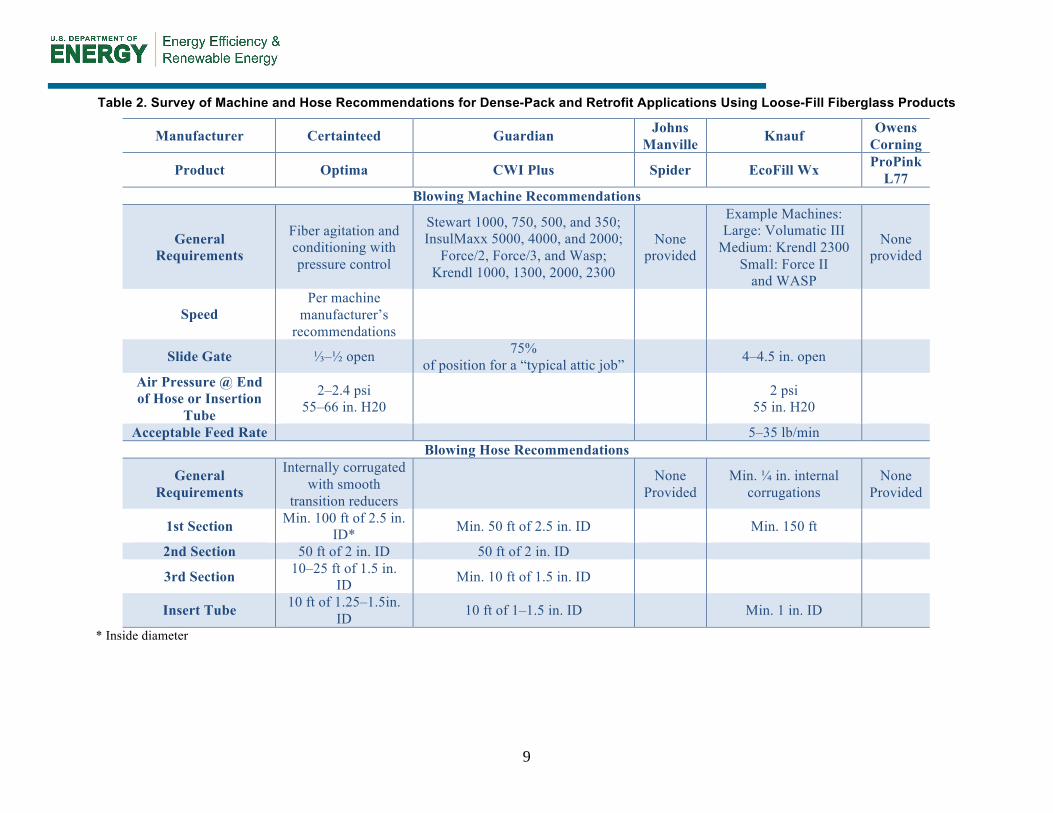
Table 1 provides a survey of the installation instructions and fill tables/coverage charts for each of the five loose-fill fiberglass insulation materials collected. The survey considered information on the product packaging and information readily available in the manufacturers’ dense-pack and weatherization/retrofit literature. Table 2 provides a survey of the machine and hose recommendations for each of the five fiberglass materials. Finally,
7
Table 3 provides a survey of the recommended installation methods/techniques for dense-pack and retrofit applications.
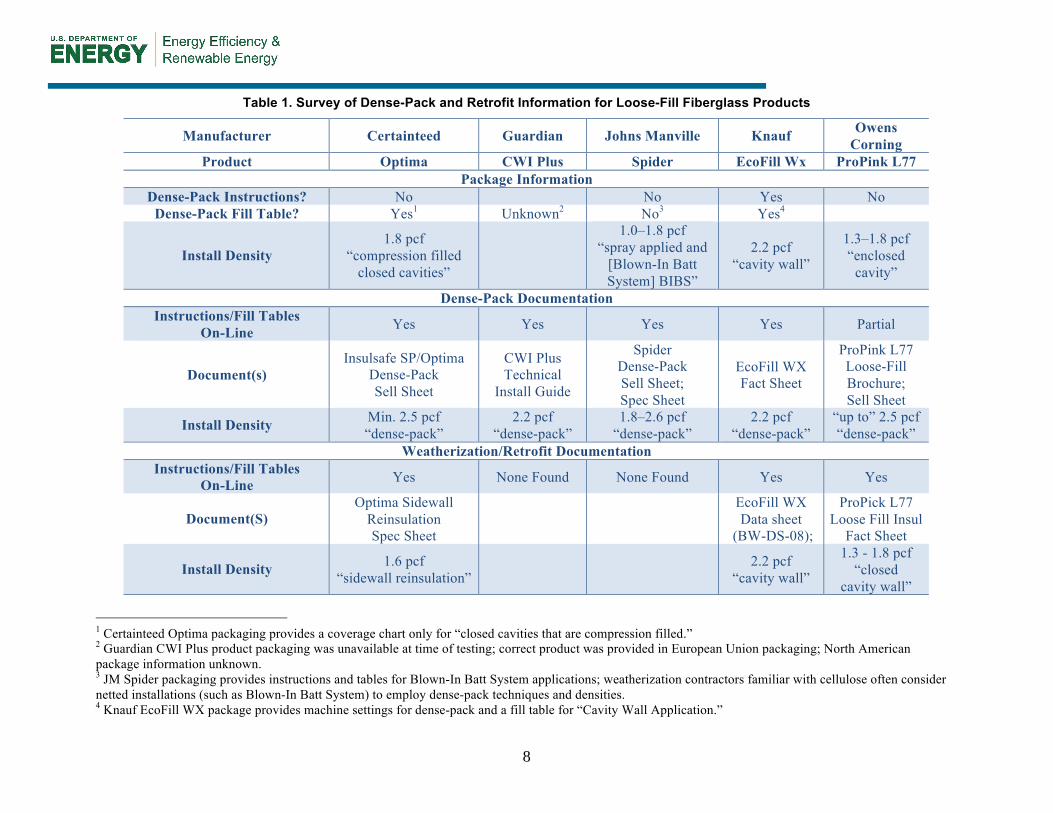
Only one of the five fiberglass products had packaging that included a dense-pack fill table. One other provided a fill table for “closed cavities that are compression filled,” which implies dense-pack application. For these two products the package-recommended dense-pack install densities were 2.2 and 1.8 pcf, respectively. The other packages provided recommended install densities of 1.0–1.8 pcf for “closed cavities.”
Where dense-pack installation instructions and fill tables are not provided on the packaging, it is reasonable for installers to seek this information online and from their local suppliers. References to dense-pack applications were found in the general documentation for four of the five products. Most documentation contained statements about the ability to dense pack to a certain density. Some documents said to install to “a minimum of” 2.5 pcf; others said install “up to” 2.5 pcf. Yet others suggested a range of dense-pack install densities (e.g., 1.8–2.6 pcf). In several cases the recommended dense-pack install densities from the packages did not agree with the separate documentation.
Through our discussions with installers we found that some are using installation instructions and fill tables from manufacturers’ weatherization and retrofit documentation. This documentation provides a third set of install densities that often contradict the information on the packaging and in other literature for the same product. The weatherization and retrofit documentation, where available, suggests install densities of 1.3–1.8 pcf for one product, 1.6 pcf for another. A third product, Knauf EcoFill Wx, instructs weatherization installers to use dense-pack methods and fill to 2.2 pcf.
Loose-fill fiberglass insulation products perform differently from cellulose insulation products. Fiberglass products are expected to have dense-pack install densities that are different from and lower than those for cellulose materials. Furthermore, there may be a range of dense-pack install densities for different fiberglass products.
8
Table 1. Survey of Dense-Pack and Retrofit Information for Loose-Fill Fiberglass Products
Manufacturer Certainteed Guardian Johns Manville Knauf Owens Corning
Product Optima CWI Plus Spider EcoFill Wx ProPink L77 Package Information
Dense-Pack Instructions? No No Yes No Dense-Pack Fill Table? Yes1 Unknown2 No3 Yes4
Install Density 1.8 pcf
“compression filled closed cavities”
1.0–1.8 pcf “spray applied and
[Blown-In Batt System] BIBS”
2.2 pcf “cavity wall”
1.3–1.8 pcf “enclosed
cavity”
Dense-Pack Documentation Instructions/Fill Tables
On-Line Yes Yes Yes Yes Partial
Document(s) Insulsafe SP/Optima
Dense-Pack Sell Sheet
CWI Plus Technical
Install Guide
Spider Dense-Pack Sell Sheet; Spec Sheet
EcoFill WX Fact Sheet
ProPink L77 Loose-Fill Brochure; Sell Sheet
Install Density Min. 2.5 pcf “dense-pack”
2.2 pcf “dense-pack”
1.8–2.6 pcf “dense-pack”
2.2 pcf “dense-pack”
“up to” 2.5 pcf “dense-pack”
Weatherization/Retrofit Documentation Instructions/Fill Tables
On-Line Yes None Found None Found Yes Yes
Document(S) Optima Sidewall
Reinsulation Spec Sheet
EcoFill WX Data sheet
(BW-DS-08);
ProPick L77 Loose Fill Insul
Fact Sheet
Install Density 1.6 pcf “sidewall reinsulation” 2.2 pcf
“cavity wall”
1.3 - 1.8 pcf “closed
cavity wall”
1 Certainteed Optima packaging provides a coverage chart only for “closed cavities that are compression filled.” 2 Guardian CWI Plus product packaging was unavailable at time of testing; correct product was provided in European Union packaging; North American package information unknown. 3 JM Spider packaging provides instructions and tables for Blown-In Batt System applications; weatherization contractors familiar with cellulose often consider netted installations (such as Blown-In Batt System) to employ dense-pack techniques and densities. 4 Knauf EcoFill WX package provides machine settings for dense-pack and a fill table for “Cavity Wall Application.”
9
Table 2. Survey of Machine and Hose Recommendations for Dense-Pack and Retrofit Applications Using Loose-Fill Fiberglass Products
Manufacturer Certainteed Guardian Johns Manville Knauf Owens
Corning
Product Optima CWI Plus Spider EcoFill Wx ProPink L77
Blowing Machine Recommendations
General Requirements
Fiber agitation and conditioning with pressure control
Stewart 1000, 750, 500, and 350; InsulMaxx 5000, 4000, and 2000;
Force/2, Force/3, and Wasp; Krendl 1000, 1300, 2000, 2300
None provided
Example Machines: Large: Volumatic III
Medium: Krendl 2300 Small: Force II
and WASP
None provided
Speed Per machine
manufacturer’s recommendations
Slide Gate ⅓–½ open 75% of position for a “typical attic job” 4–4.5 in. open
Air Pressure @ End of Hose or Insertion
Tube
2–2.4 psi 55–66 in. H20 2 psi
55 in. H20
Acceptable Feed Rate 5–35 lb/min Blowing Hose Recommendations
General Requirements
Internally corrugated with smooth
transition reducers None
Provided Min. ¼ in. internal
corrugations None
Provided
1st Section Min. 100 ft of 2.5 in. ID* Min. 50 ft of 2.5 in. ID Min. 150 ft
2nd Section 50 ft of 2 in. ID 50 ft of 2 in. ID
3rd Section 10–25 ft of 1.5 in. ID Min. 10 ft of 1.5 in. ID
Insert Tube 10 ft of 1.25–1.5in. ID 10 ft of 1–1.5 in. ID Min. 1 in. ID
* Inside diameter
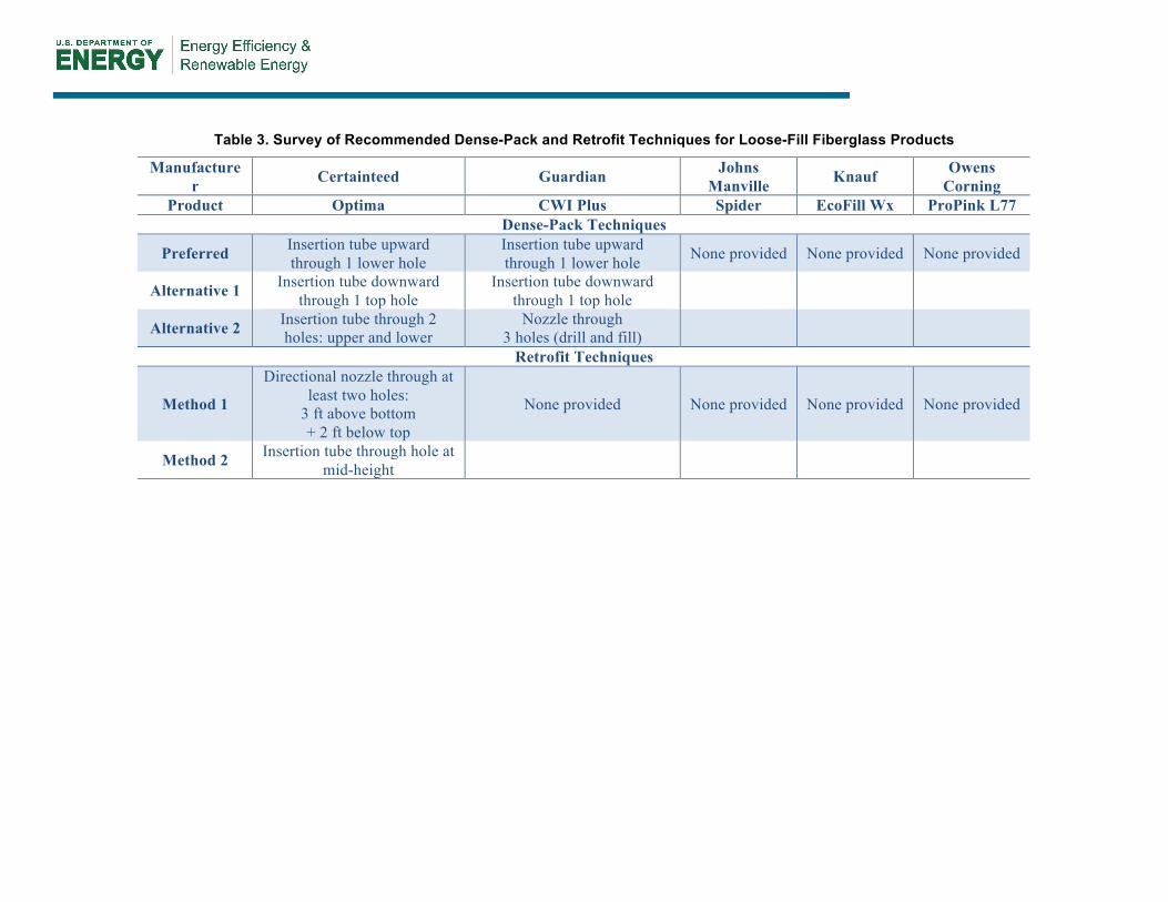
Table 3. Survey of Recommended Dense-Pack and Retrofit Techniques for Loose-Fill Fiberglass Products
Manufacturer Certainteed Guardian Johns
Manville Knauf Owens Corning
Product Optima CWI Plus Spider EcoFill Wx ProPink L77 Dense-Pack Techniques
Preferred Insertion tube upward through 1 lower hole
Insertion tube upward through 1 lower hole None provided None provided None provided
Alternative 1 Insertion tube downward through 1 top hole
Insertion tube downward through 1 top hole
Alternative 2 Insertion tube through 2 holes: upper and lower
Nozzle through 3 holes (drill and fill)
Retrofit Techniques
Method 1
Directional nozzle through at least two holes:
3 ft above bottom + 2 ft below top
None provided None provided None provided None provided
Method 2 Insertion tube through hole at mid-height
buildingsciencecorporation
Typewritten Text
10

Only one of the five materials collected had consistent instructions and recommended install densities between the packaging, dense-pack documentation and weatherization retrofit documentation. In all other cases the installer is faced with a range of instructions and install densities to work toward. Greater clarity and consistency are needed in the installation instructions and recommended install densities for fiberglass products used in dense-pack retrofit applications.
2.4 Installation Methods and Densities for Test Wall Specimens The experimental program for this work was modified to address the range of installation methods and install densities provided on the material packaging and in other documentation from the five loose-fill fiberglass insulation manufacturers. None of the stone wool insulation manufacturers support dense-pack applications, so none provided any directions or target densities for this application. The same insulation techniques and target densities were used for fiberglass and stone wool products.
The InsulMaxx 2000 machine was set up with 150 ft of internally corrugated hose with smooth transitions down to either a 2-in. ID nozzle or an 8-ft. long, 1.25-in. ID insertion tube. Test wall specimens were prepared using three installation methods:
• Bottom fill. The insertion tube was fed into the cavity, upward through one lower hole and drilled at approximately 24 in. above the bottom plate, until it was approximately 6 in. from the top of the cavity. The cavity was filled with insulation and the tube was slowly withdrawn as the cavity filled, the material compressed, and the feed rate slowed. This method most closely reflects the install method used for dense-packing cellulose. However, to achieve the lower densities recommended for fiberglass materials, the tube must be removed before the material flow comes to a complete stop and, unlike cellulose dense-packing, the tube is not pulled out and pushed part way back in.
• Top fill. The insertion tube was fed into the cavity, downward through one top hole and drilled at approximately 6 in. below the top plates, until it was approximately 6 in. from the bottom of the cavity. The cavity was filled with insulation and the tube was slowly withdrawn as the cavity filled, the material compressed, and the feed rate slowed.
• Two-inch nozzle. The cavity was filled with a 2-in. ID nozzle, using a “two-hole” or “three-hole” approach. The nozzle was introduced first through a lower hole and drilled at approximately 24 in. above the bottom plate. Insulation was filled first downward and then upward until it reached the level of an upper hole and drilled at approximately 24 in. below the top plates. The nozzle was then moved to the upper hole and insulation was filled upward until it reached the top of the cavity. When using the “three-hole” variation, the nozzle was inserted into the top hole and drilled approximately 6 in. below the top plates. Then material was added until the insulation was slightly packed.
The fiberglass insulation packaging and other documentation suggest a range of installation densities covering 1.0–2.6 pcf. We set out to prepare test wall specimens to address everything from median densities recommended for weatherization/retrofit/reinsulation applications (e.g., 1.5–1.8 pcf) to the higher densities clearly intended for dense-pack (e.g., 2.2–2.6 pcf) and even into higher fiberglass dense-pack densities reported by some installers (e.g., 3.0 pcf). We
buildingsciencecorporation
Typewritten Text
buildingsciencecorporation
Typewritten Text
buildingsciencecorporation
Typewritten Text
buildingsciencecorporation
Typewritten Text
11
intentionally avoided the lowest densities listed in “closed cavity” fill tables on packaging (e.g., 1.0 to < 1.5 pcf), expecting that they would not provide any effective airflow resistance.
2.5 Other Experimental Methods Other aspects of the test wall specimen preparation and airflow resistance testing followed the procedures summarized by Schumacher (2011). Installation techniques were refined and machine settings were established using the same density box method that was used for the previous cellulose tests. The installed material density was established using the same apparatus and methods as used for the cellulose tests. Finally, the background air leakage, short-path airflow test, and long-path airflow tests were conducted using the same equipment and methods as used for the cellulose tests.
buildingsciencecorporation
Typewritten Text
buildingsciencecorporation
Typewritten Text
12
buildingsciencecorporation
Typewritten Text
3 Results and Discussion
This section provides a summary of airflow resistance test results for select fiberglass and stone wool insulation materials.
3.1 Test Program Three loose-fill fiberglass insulation products were randomly selected from the five collected. Only one stone wool product was collected and tested. Only Building Science Laboratories staff know which manufacturers’ materials were used in the testing; the reporting is done using material codes (e.g., tests A1, A2, and A3 represent tests 1, 2, and 3 conducted using material from manufacturer A). This reporting method was also used in the cellulose tests reported by Schumacher (2011). To avoid confusion with the previously completed cellulose test results, the three fiberglass materials tested were designated with letters O, P, and Q; the lone stone wool product was designated with letter R.
Test wall specimens were prepared to cover the range of densities identified on the packaging and in other documentation: roughly 1.8–2.5 pcf.
3.2 General Airflow Test Results Roughly 16 fiberglass test wall specimens and three stone wool test wall specimens were prepared and tested.
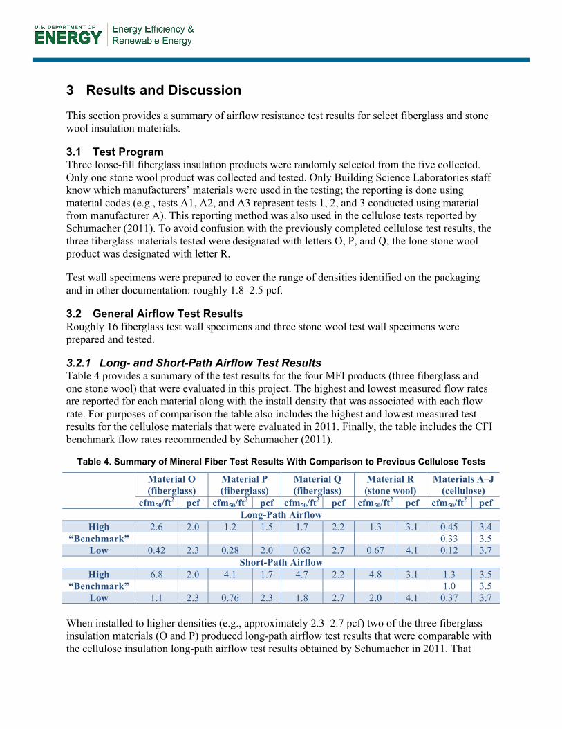
3.2.1 Long- and Short-Path Airflow Test Results Table 4 provides a summary of the test results for the four MFI products (three fiberglass and one stone wool) that were evaluated in this project. The highest and lowest measured flow rates are reported for each material along with the install density that was associated with each flow rate. For purposes of comparison the table also includes the highest and lowest measured test results for the cellulose materials that were evaluated in 2011. Finally, the table includes the CFI benchmark flow rates recommended by Schumacher (2011).
Table 4. Summary of Mineral Fiber Test Results With Comparison to Previous Cellulose Tests
Material O (fiberglass)
Material P (fiberglass)
Material Q (fiberglass)
Material R (stone wool)
Materials A–J (cellulose)
cfm50/ft2 pcf cfm50/ft2 pcf cfm50/ft2 pcf cfm50/ft2 pcf cfm50/ft2 pcf Long-Path Airflow
High 2.6 2.0 1.2 1.5 1.7 2.2 1.3 3.1 0.45 3.4 “Benchmark” 0.33 3.5
Low 0.42 2.3 0.28 2.0 0.62 2.7 0.67 4.1 0.12 3.7 Short-Path Airflow
High 6.8 2.0 4.1 1.7 4.7 2.2 4.8 3.1 1.3 3.5 “Benchmark” 1.0 3.5
Low 1.1 2.3 0.76 2.3 1.8 2.7 2.0 4.1 0.37 3.7 When installed to higher densities (e.g., approximately 2.3–2.7 pcf) two of the three fiberglass insulation materials (O and P) produced long-path airflow test results that were comparable with the cellulose insulation long-path airflow test results obtained by Schumacher in 2011. That
buildingsciencecorporation
Typewritten Text
13
testing established long- and short-path airflow “benchmarks” of 0.33 and 1.0 cfm50/ft2, respectively, for historical dense-pack cellulose retrofits installed to 3.5 pcf. Again, when installed to higher densities (e.g., higher than approximately 2.3–2.7 pcf), two of the fiberglass insulation materials (O and P) produced short-path airflow test results that were comparable with the cellulose insulation short-path airflow test results obtained in 2011. The measured performance of the fiberglass test wall specimens depended highly on the material tested and the installation method. These issues are discussed further in Section 3.3 of this report.
The long- and short-path airflow tests for the stone wool insulation resulted in airflow rates that were 1.5–2 times higher than the cellulose tests, despite the fact that the stone wool was installed at higher densities (e.g., 3.1–4.1 pcf).
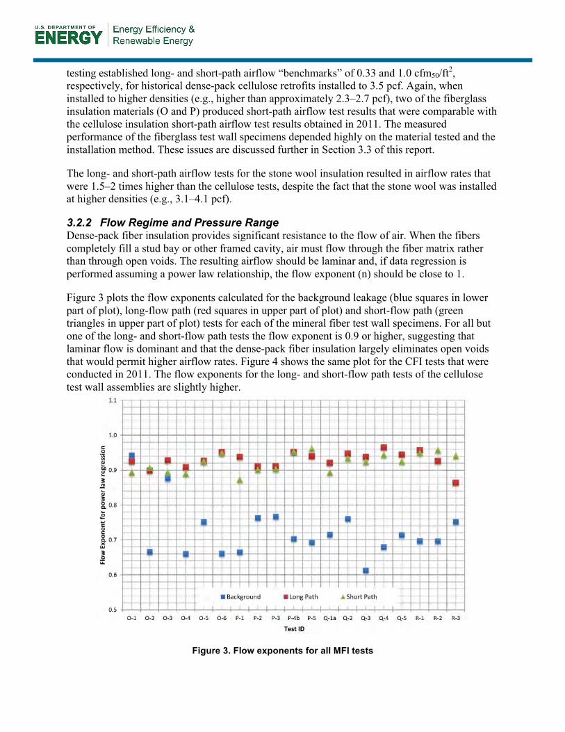
3.2.2 Flow Regime and Pressure Range Dense-pack fiber insulation provides significant resistance to the flow of air. When the fibers completely fill a stud bay or other framed cavity, air must flow through the fiber matrix rather than through open voids. The resulting airflow should be laminar and, if data regression is performed assuming a power law relationship, the flow exponent (n) should be close to 1.
Figure 3 plots the flow exponents calculated for the background leakage (blue squares in lower part of plot), long-flow path (red squares in upper part of plot) and short-flow path (green triangles in upper part of plot) tests for each of the mineral fiber test wall specimens. For all but one of the long- and short-flow path tests the flow exponent is 0.9 or higher, suggesting that laminar flow is dominant and that the dense-pack fiber insulation largely eliminates open voids that would permit higher airflow rates. Figure 4 shows the same plot for the CFI tests that were conducted in 2011. The flow exponents for the long- and short-flow path tests of the cellulose test wall assemblies are slightly higher.
Figure 3. Flow exponents for all MFI tests
buildingsciencecorporation
Typewritten Text
buildingsciencecorporation
Typewritten Text
buildingsciencecorporation
Typewritten Text
14

15
Figure 4. Flow exponents for previous CFI tests
(Schumacher 2011) 3.3 Influence of Material and Installation Method This section discusses the individual airflow test results for the three fiberglass and one stone wool materials tested. The influences of material and installation method are addressed.
3.3.1 Material O Density box specimens for Material O were first prepared using the bottom fill installation method. However, we were unable to produce acceptable specimens with densities lower than 2.8–3.2 pcf. When lower test specimen densities were achieved using this method, the material was clearly not evenly distributed. For this reason we opted not to produce any full test wall specimens using the bottom fill method. Instead, we sought to produce test wall specimens with densities of 1.8–2.5 pcf using the top fill and 2-in. nozzle installation methods.
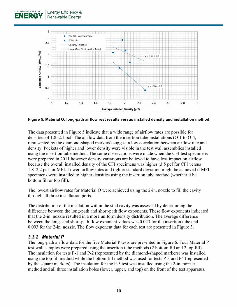
The long-path airflow data for the six Material O tests are presented in Figure 5. Four of the Material O airflow tests were performed on samples installed using the top fill installation method (i.e., using the 8-ft insertion tube through the top installation hole). The remaining two airflow tests were performed on samples installed using just the 2-in. nozzle method (i.e., installed through the lower, upper, and top access holes on the front of the test apparatus).
16
Figure 5. Material O: long-path airflow rest results versus installed density and installation method
The data presented in Figure 5 indicate that a wide range of airflow rates are possible for densities of 1.8–2.1 pcf. The airflow data from the insertion tube installations (O-1 to O-4, represented by the diamond-shaped markers) suggest a low correlation between airflow rate and density. Pockets of higher and lower density were visible in the test wall assemblies installed using the insertion tube method. The same observations were made when the CFI test specimens were prepared in 2011 however density variations are believed to have less impact on airflow because the overall installed density of the CFI specimens was higher (3.5 pcf for CFI versus 1.8–2.2 pcf for MFI. Lower airflow rates and tighter standard deviation might be achieved if MFI specimens were installed to higher densities using the insertion tube method (whether it be bottom fill or top fill).
The lowest airflow rates for Material O were achieved using the 2-in. nozzle to fill the cavity through all three installation ports.
The distribution of the insulation within the stud cavity was assessed by determining the difference between the long-path and short-path flow exponents. These flow exponents indicated that the 2-in. nozzle resulted in a more uniform density distribution. The average difference between the long- and short-path flow exponent values was 0.023 for the insertion tube and 0.003 for the 2-in. nozzle. The flow exponent data for each test are presented in Figure 3.
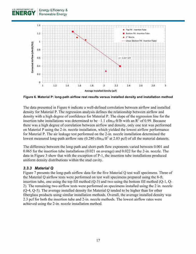
3.3.2 Material P The long-path airflow data for the five Material P tests are presented in Figure 6. Four Material P test wall samples were prepared using the insertion tube methods (2 bottom fill and 2 top fill). The insulation for tests P-1 and P-2 (represented by the diamond-shaped markers) was installed using the top fill method while the bottom fill method was used for tests P-3 and P4 (represented by the square markers). The insulation for the P-5 test was installed using the 2-in. nozzle method and all three installation holes (lower, upper, and top) on the front of the test apparatus.
17
Figure 6. Material P: long-path airflow rest results versus installed density and installation method
The data presented in Figure 6 indicate a well-defined correlation between airflow and installed density for Material P. The regression analysis defines the relationship between airflow and density with a high degree of confidence for Material P. The slope of the regression line for the insertion tube installations was determined to be –1.1 cfm50·ft/lb with an R2 of 0.99. Because there was a high degree of correlation between airflow and density, only one test was performed on Material P using the 2-in. nozzle installation, which yielded the lowest airflow performance for Material P. The air leakage test performed on the 2-in. nozzle installation determined the lowest measured long-path airflow rate (0.280 cfm50/ft2 at 2.03 pcf) of all the material datasets.
The difference between the long-path and short-path flow exponents varied between 0.001 and 0.065 for the insertion tube installations (0.021 on average) and 0.022 for the 2-in. nozzle. The data in Figure 3 show that with the exception of P-1, the insertion tube installations produced uniform density distributions within the stud cavity.
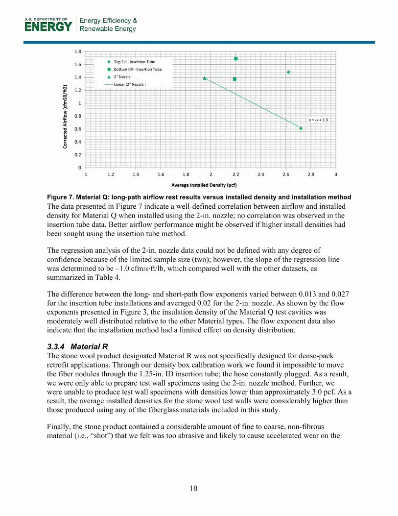
3.3.3 Material Q Figure 7 presents the long-path airflow data for the five Material Q test wall specimens. Three of the Material Q airflow tests were performed on test wall specimens prepared using the 8-ft. insertion tube, one using the top fill method (Q-3) and two using the bottom fill method (Q-1, Q-2). The remaining two airflow tests were performed on specimens installed using the 2 in. nozzle (Q-4, Q-5). The average installed density for Material Q tended to be higher than for other fiberglass products using similar installation methods. Overall, the average installed density was 2.3 pcf for both the insertion tube and 2-in. nozzle methods. The lowest airflow rates were achieved using the 2-in. nozzle installation method.
18
Figure 7. Material Q: long-path airflow rest results versus installed density and installation method The data presented in Figure 7 indicate a well-defined correlation between airflow and installed density for Material Q when installed using the 2-in. nozzle; no correlation was observed in the insertion tube data. Better airflow performance might be observed if higher install densities had been sought using the insertion tube method.
The regression analysis of the 2-in. nozzle data could not be defined with any degree of confidence because of the limited sample size (two); however, the slope of the regression line was determined to be –1.0 cfm50·ft/lb, which compared well with the other datasets, as summarized in Table 4.
The difference between the long- and short-path flow exponents varied between 0.013 and 0.027 for the insertion tube installations and averaged 0.02 for the 2-in. nozzle. As shown by the flow exponents presented in Figure 3, the insulation density of the Material Q test cavities was moderately well distributed relative to the other Material types. The flow exponent data also indicate that the installation method had a limited effect on density distribution.
3.3.4 Material R The stone wool product designated Material R was not specifically designed for dense-pack retrofit applications. Through our density box calibration work we found it impossible to move the fiber nodules through the 1.25-in. ID insertion tube; the hose constantly plugged. As a result, we were only able to prepare test wall specimens using the 2-in. nozzle method. Further, we were unable to produce test wall specimens with densities lower than approximately 3.0 pcf. As a result, the average installed densities for the stone wool test walls were considerably higher than those produced using any of the fiberglass materials included in this study.
Finally, the stone product contained a considerable amount of fine to coarse, non-fibrous material (i.e., “shot”) that we felt was too abrasive and likely to cause accelerated wear on the

fiber moving equipment in dense-pack retrofit applications. The number of airflow tests performed on this sample was limited to three because this product is highly abrasive.
Figure 8. Material R: long-path airflow rest results versus installed density and installation method
Data from the airflow tests performed on this material demonstrated a consistent increase in airflow resistance with density; these data are presented in Figure 8. In light of the small dataset, the slope of the regression line indicates that the airflow through this material changes at a rate of –0.7 cfm50·ft/lb. This number compares well with the regression slopes observed in the fiberglass samples that were installed using the 2-in. nozzle; however, the densities are significantly higher. The lowest airflow rates for Material R were achieved with densities of 3.9 and 4.1 pcf. The corrected airflow rates associated with each of these densities were 0.74 and 0.67 cfm50/ft2, respectively.
These results also indicate that the resistance to airflow increases more slowly with density than what was observed in the fiberglass samples. This relationship may change if testing was completed using a more refined mineral wool product without the non-fibrous material (i.e., various sizes of solidified blobs or balls of molten rock, referred to as shot).
3.3.5 Installation Methods Based on manufacturers’ instructions on packaging and in other documentation, three installation methods were tested. The installation experience and airflow test results collected under laboratory conditions suggest that the 2-in. nozzle installation method results in more even material distribution and lower long- and short-path airflow rates (i.e., higher airflow resistance) than either of the insertion tube methods (i.e., top or bottom). Also, many installers are familiar with nozzle installation methods because they are commonly used for installing cellulose fiber or fiberglass insulation in netted-and-blown installations (e.g., Blown-In Batt System).
However, in netted-and-blown applications installers can easily see the “fill” of the cavity space through the netting and assess distribution and density by touch (i.e., by pushing on the netting). In netted-and-blown applications cavity spaces can be filled completely and to sufficient density
19
to minimize the potential for settling. In retrofit applications, loose-fill insulation materials are installed in existing cavities that are bounded by opaque, stiff materials (e.g., framing, sheathing, plaster, wall board) so the installer can neither see into the cavity space to assess fill nor touch the surface of the insulation to assess distribution and density. The insertion tube installation methods were (in part) developed to address these problems.
Weatherization contractors and dense-pack installers are trained to understand different framing methods and to site-assess framing conditions to identify obstructions (e.g., blocking) that might prevent all cavities from being completely filled with insulation. Insertion tubes are graduated (i.e., typically marked at 1-ft intervals). Installers are taught to use the insertion tube to “probe” the bounds of cavities to identify obstructions as they are installing. The insertion tube is pushed to the furthest reaches of the cavity to confirm that dimensions are as expected. The insertion tube is withdrawn only a few inches before starting to fill the cavity. This ensures that insulation is delivered to the far end of the cavity without catching on partial obstructions and creating an uninsulated space or pocket, as is possible when using a nozzle installation method.
Some installers use the nozzle installation method for dense-pack retrofit applications. This testing supports the belief that good airflow resistance can be achieved using the nozzle installation method. However, given the realities discussed in the previous paragraph, insertion tube installation methods should be considered best practice for retrofit applications. If the only goal of an insulation retrofit is to fill cavities with insulation, insertion tube installation methods should be recommended and lower density installs can be accepted (assuming density is sufficient to prevent settling). However, if the goals are to fill cavities with insulation and to reduce airflow in and through assemblies, insertion tube installation methods should be accepted and install densities should be established to provide sufficient airflow resistance.
This research sought to evaluate test wall specimens installed to the manufacturer-recommended densities, using the methods identified in the various manufacturers’ literature. If the goal is to provide comparable airflow resistance to the benchmarks for historical dense-pack cellulose retrofits (i.e., long-path airflow of 0.33 cfm50/ft2 and short-path airflow of 1.0 cfm50/ft2), further testing is necessary to establish recommended install densities for insertion tube installation methods.
20
4 Conclusions and Recommendations
This report documents airflow resistance test results for dense-pack retrofit applications using MFI materials (i.e., glass fiber and stone wool). The test results are compared to previous airflow resistance tests for dense-pack retrofit applications using 10 different CFI materials.
Loose-fill MFI products (i.e., fiberglass and stone wool) have different fiber structures than CFI and, as a result, mineral fiber products are expected to require different installation densities than cellulose insulation products. However, the recommended installation methods and densities for fiberglass products are unclear. Only one of the five fiberglass materials collected had consistent instructions and recommended install densities between the packaging, dense-pack documentation and weatherization/retrofit documentation. In all other cases the installer is faced with a range of instructions and install densities to work toward. Greater clarity and consistency are needed in the installation instructions and recommended install densities for fiberglass products used in dense-pack retrofit applications.
Airflow resistance varied significantly between loose-fill fiberglass products, even though all the compared products are marketed and supported for use in dense-pack retrofit applications. When these fiberglass products were installed at approximately 2.2 pcf, the variance was 0.33–1.73 cfm50/ft2. The distribution of the installed material, and thus the airflow resistance, also depend on installation method. In this testing we sought to qualitatively and quantitatively assess the three installation methods identified in our survey of instructions from packaging and information from dense-pack and weatherization/retrofit documentation: (1) bottom fill, using an insertion tube installed up through a hole at approximately 24 in. above the bottom plate; (2) top fill, using an insertion tube installed down through a hole at approximately 6 in. below the top plates; and (3) 2 in. nozzle, installed through two or three holes (e.g., at holes approximately 24 in., 72 in. and 90 in. above the bottom plate).
Two of the three loose-fill fiberglass products tested (installed at approximately 2.3 pcf) produced long-path flow rates of 0.28 and 0.42 cfm50/ft2 and short-path airflow rates of 0.76 and 1.1 cfm50/ft2. These are comparable to the cellulose dense-pack retrofits benchmarks of 0.33 and 1.0 cfm50/ft2 for the long- and short-path airflow rates, respectively (CFI installed at 3.5 pcf as required by BPI). However, the fiberglass test walls were prepared using the 2-in. nozzle installation method, not the insertion tube methods recommended as best practice for retrofit applications. These results indicate that there is potential for dense-pack applications of MFI, but that more work needs to be done to develop appropriate standards for real-world installation needs. In particular, further testing should be conducted to establish recommended install densities for insertion tube installation methods.
Finally, none of the stone wool manufacturers support dense-pack retrofit applications using their products. Only one loose-fill stone wool insulation product was collected for testing. The stone wool fibers and nodules were too large to successfully install using either of the insertion tube techniques. Loose-fill stone wool is not recommended for dense-pack retrofit applications.
21
References
BPI (2010) BPI–103 “Standard Test Method for Thermal Insulation Materials Used in Air Retarder Applications.” Malta, NY: Building Performance Institute.
EDU (1986). “Research Shows Increased Building Tightness with Cellulose Insulation.” Energy Design Update, vol. 5, no. 12, December 1986.
Schumacher, C. (2011). Building America Report 1109, High Impact Project – Support of Standards Development: Dense-pack Airflow Resistance, Final Research Report. Somerville, MA: Building Science Corporation.
22
Appendix A: Loose-Fill Fiberglass Insulation Products for Dense-Pack Retrofit Applications
• Certainteed Optima • Guardian CWI Plus
• Johns Manville Spider • Knauf EcoFill-WX
• Owens Corning ProPink L77
23

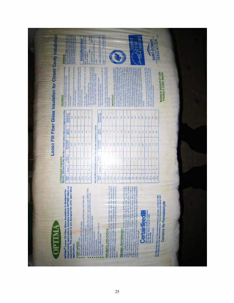
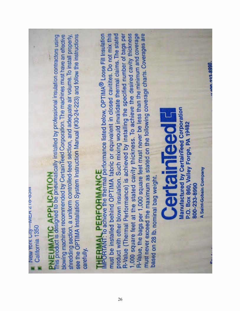
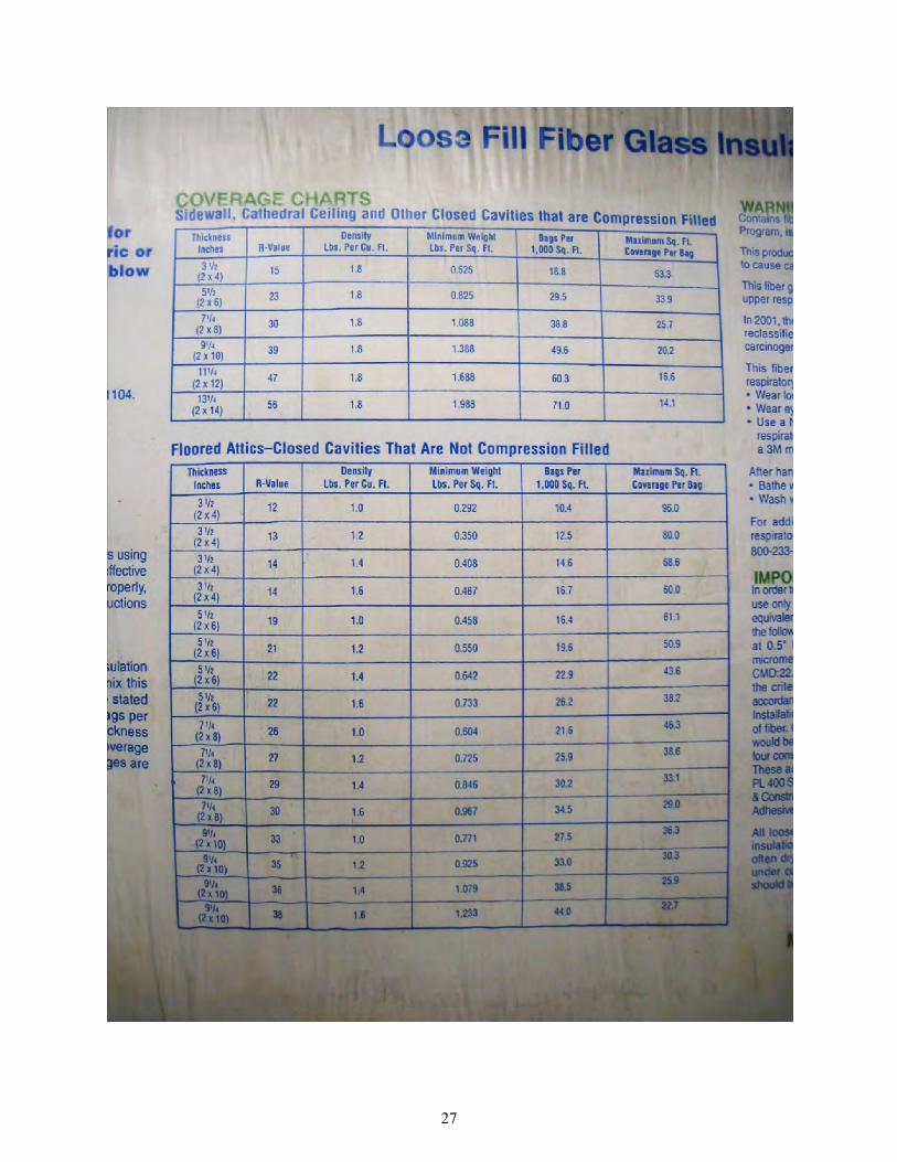
Appendix A1.1: Certainteed Optima Documentation on Material Packaging
24
25
26
27

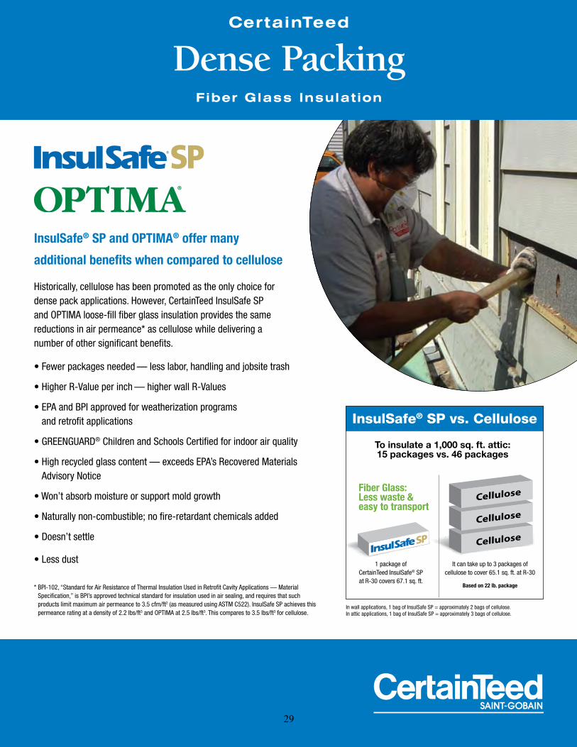
Appendix A1.2: Certainteed Optima Documentation for Dense-Packing Sell Sheet, “Certainteed Dense Packing Fiberglass Insulation”
28
CertainTeed
Dense Packing
Historically, cellulose has been promoted as the only choice for dense pack applications. However, CertainTeed InsulSafe SP and OPTIMA loose-fill fiber glass insulation provides the same reductions in air permeance* as cellulose while delivering a number of other significant benefits.
* BPI-102, “Standard for Air Resistance of Thermal Insulation Used in Retrofit Cavity Applications — Material Specification,” is BPI’s approved technical standard for insulation used in air sealing, and requires that such products limit maximum air permeance to 3.5 cfm/ft2 (as measured using ASTM C522). InsulSafe SP achieves this permeance rating at a density of 2.2 lbs/ft3 and OPTIMA at 2.5 lbs/ft3. This compares to 3.5 lbs/ft3 for cellulose.
InsulSafe® SP and OPTIMA® offer many
additional benefits when compared to cellulose
and retrofit applications
® Children and Schools Certified for indoor air quality
Fiber Glass Insulation
Cellulose
Cellulose
Cellulose
1 package of CertainTeed InsulSafe® SP at R-30 covers 67.1 sq. ft.
It can take up to 3 packages of cellulose to cover 65.1 sq. ft. at R-30
Based on 22 lb. package
Fiber Glass: Less waste & easy to transport
To insulate a 1,000 sq. ft. attic: 15 packages vs. 46 packages
InsulSafe® SP vs. Cellulose
In wall applications, 1 bag of InsulSafe SP = approximately 2 bags of cellulose. In attic applications, 1 bag of InsulSafe SP = approximately 3 bags of cellulose.
29

Dense Packing Installation Guidelines for InsulSafe SP® and OPTIMA®
Blowing Machine: with air pressure control 1. Machine speed — per manufacturer’s recommendation 2. Slide gate — start with 1/3 to 1/2 open 3. Air pressure — 2.0 to 2.4 psi (55" to 66" of H2O)
(machine back pressure end of insert tube) 4. Transmission (if applicable) — 2nd gear
Blowing Hose: 1. Internally corrugated hose required (except for wall insert tube) 2. Smooth transition reducers 3. 10' cavity insert tube:
(2 x 6 or larger)
c. 1½" or 2" blow hose inserted into floor/ceiling cavities or large sidewall cavities from the attic
Blowing Hose Assembly
Machine Outlet Dia. 1st Section Reduce
to2nd
SectionReduce
to3rd
Section Reduce to 4th Section Reduce to 5th
Section
4" 4" x 0 - 25' then reduce to 3" follow 3" machine outlet set up
3½" 3½" x 0 - 25' then reduce to 3" follow 3" machine outlet set up
3" 3" x 50' min. 2½" 2½" x 50' 2" 2" x 50' 1½" 1½" x 10 - 25' Insert Tube 10'
2½" 2½" x 100' min. 2" 2" x 50' 1½" 1½" x 10 - 25' Insert Tube 10'
www.certainteed.com/insulation
CertainTeed Corporation P.O. Box 860
Valley Forge, PA 19482
Professional: 800-233-8990 Consumer: 800-782-8777
© 3/11 CertainTeed Corporation 30-24-325
ASK ABOUT ALL OF OUR OTHER CERTAINTEED® PRODUCTS AND SYSTEMS:
CertainTeed Fiber Glass Insulation Dense Pack Coverage Charts
INSULSAFE® SP OPTIMA®
FramingCavity Depth (inches)
R-Value Coverage (max. ft2/pkg.)
Weight (min. lbs/ ft2)
Packages (min. /1,000 ft2) Framing
Cavity Depth (inches)
R-Value Coverage (max. ft2/pkg.)
Weight (min. lbs/ ft2)
Packages (min. /1,000 ft2)
2 x 4 3½ 15 0.642 20.7 2 x 4 3½ 15 0.729 26.02 x 4 35/ 15 46.6 0.665 21.4 2 x 4 35/ 15 37.1 0.755 27.02 x 4 4 17 42.3 0.733 23.7 2 x 4 4 17 33.62 x 6 5½ 23 30.7 32.5 2 x 6 5½ 23 24.4 1.146 40.9
7¼ 30 23.3 1.329 42.9 7¼ 30 1.510 53.92 x 10 9¼ 39 1.696 54.7 2 x 10 9¼ 39 14.5 1.927
3 3
Techniques: 1. Preferred — 1 hole w/ tube inserted upwards 2. Alternative — 1 hole w/ tube inserted downwards or 2 holes with insert tube
NOTE: Please ensure you are in compliance with applicable
www.wapcertainsuccess.com
30
Appendix A1.3: Certainteed Optima Documentation for Weatherization / Retrofit Specification Sheet, “Optima Fiber Glass Loose-Fill Insulation for Sidewall Reinsulation”
31
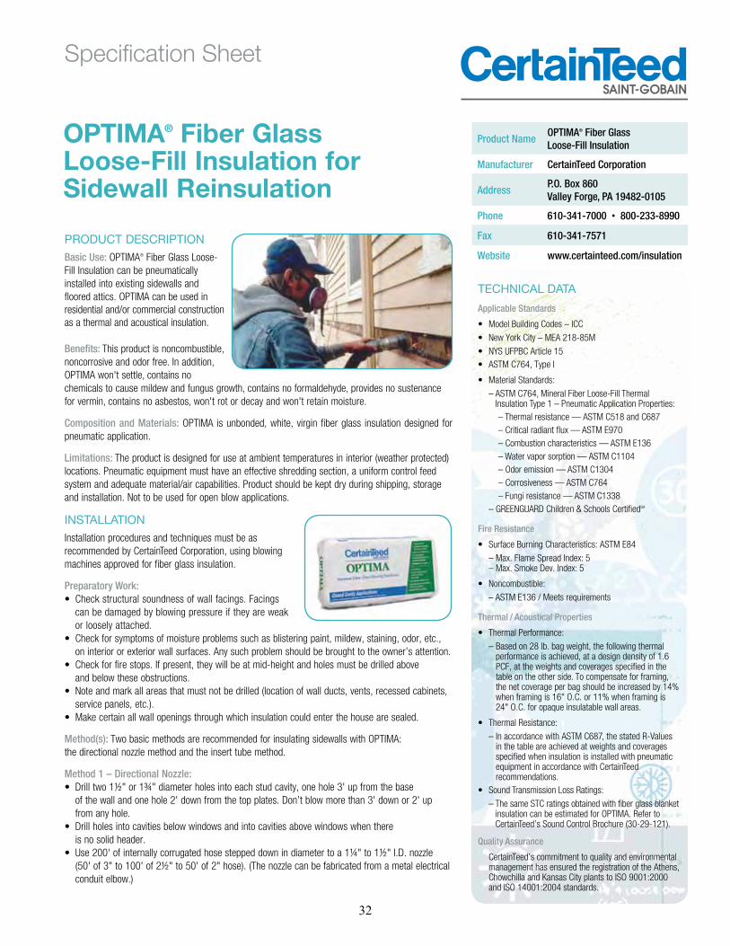
PRODUCT DESCRIPTIONBasic Use: OPTIMA® Fiber Glass Loose-Fill Insulation can be pneumatically installed into existing sidewalls and floored attics. OPTIMA can be used in residential and/or commercial construction as a thermal and acoustical insulation.
Benefits: This product is noncombustible, noncorrosive and odor free. In addition, OPTIMA won't settle, contains no chemicals to cause mildew and fungus growth, contains no formaldehyde, provides no sustenance for vermin, contains no asbestos, won't rot or decay and won't retain moisture.
Composition and Materials: OPTIMA is unbonded, white, virgin fiber glass insulation designed for pneumatic application.
Limitations: The product is designed for use at ambient temperatures in interior (weather protected) locations. Pneumatic equipment must have an effective shredding section, a uniform control feed system and adequate material/air capabilities. Product should be kept dry during shipping, storage and installation. Not to be used for open blow applications.
INSTALLATIONInstallation procedures and techniques must be as recommended by CertainTeed Corporation, using blowing machines approved for fiber glass insulation.
Preparatory Work:
can be damaged by blowing pressure if they are weak or loosely attached.
Check for symptoms of moisture problems such as blistering paint, mildew, staining, odor, etc., on interior or exterior wall surfaces. Any such problem should be brought to the owner’s attention.
Check for fire stops. If present, they will be at mid-height and holes must be drilled above and below these obstructions. Note and mark all areas that must not be drilled (location of wall ducts, vents, recessed cabinets, service panels, etc.). Make certain all wall openings through which insulation could enter the house are sealed.
Method(s): Two basic methods are recommended for insulating sidewalls with OPTIMA: the directional nozzle method and the insert tube method.
Method 1 – Directional Nozzle: Drill two 1½" or 1¾" diameter holes into each stud cavity, one hole 3' up from the base of the wall and one hole 2' down from the top plates. Don’t blow more than 3' down or 2' up from any hole. Drill holes into cavities below windows and into cavities above windows when there is no solid header. Use 200' of internally corrugated hose stepped down in diameter to a 1¼" to 1½" I.D. nozzle (50' of 3" to 100' of 2½" to 50' of 2" hose). (The nozzle can be fabricated from a metal electrical conduit elbow.)
Product Name OPTIMA® Fiber Glass Loose-Fill Insulation
Manufacturer CertainTeed Corporation
Address P.O. Box 860 Valley Forge, PA 19482-0105
Phone 610-341-7000 800-233-8990
Fax 610-341-7571
Website www.certainteed.com/insulation
TECHNICAL DATA
Applicable Standards
New York City MEA 218-85M
ASTM C764, Type I
GREENGUARD Children & Schools CertifiedSM
Fire Resistance
Max. Flame Spread Index: 5Max. Smoke Dev. Index: 5
Thermal / Acoustical Properties
28 lb. bag weight, the following thermal performance is achieved, at a design density of 1.6 PCF, at the weights and coverages specified in the table on the other side. To compensate for framing, the net coverage per bag should be increased by 14% when framing is 16" O.C. or 11% when framing is 24" O.C. for opaque insulatable wall areas.
In accordance with ASTM C687, the stated R-Values in the table are achieved at weights and coverages specified when insulation is installed with pneumatic equipment in accordance with CertainTeed recommendations.
The same STC ratings obtained with fiber glass blanket insulation can be estimated for OPTIMA. Refer to CertainTe -121).
Quality Assurance
CertainTeed’s commitment to quality and environmental management has ensured the registration of the Athens,
and ISO 14001:2004 standards.
OPTIMA® Fiber Glass Loose-Fill Insulation for Sidewall Reinsulation
SPOT: PMS 300 & PMS 425
Specification Sheet
32

R-Value Bags Per 1000 sq. ft. Maximum Net Coverage Minimum Weight/sq. ft. Minimum Thickness
To obtain a thermal resistance (R) of:
Bags per 1000 sq. ft. of net area
Contents of bag should not cover more than: (sq. ft.)
Weight per sq. ft. of installed insulation should not be
less than: (lbs.)
Installed insulation should not be less than: (in.)
30 34.5 7-1/4
22 26.3 38 0.733 5-1/2
16 53 0.533 4
15 17.2 58 0.483 3-5/8
14 16.7 60 0.467 3-1/2
For dense packing walls to an air permeance of 3.5 cfm/ft2 at 50 pascals pressure differential, use a minimum density of at least 2.25 pcf.
www.certainteed.com/insulation
Insert nozzle in lower hole first and blow downward, filling cavity up to the level of the hole. Insert nozzle in upper hole and blow downward and then upward until the cavity is completely filled.
In both methods, air pressure must be reduced substantially compared to the open blow technique to ensure that no damage is done to the sidewall. The blowing machine should be equipped with an air relief valve.
The actual setting of the equipment will vary depending on the type of hose,
should have a nominal density of 1.6 lbs. per cubic foot.
Method 2 – Insert Tube:
there is no solid header.½" to 50' of 2"
hose). The 2" hose is connected to a reducer and then to a 4' length of 1¼" to 1½" I.D. semi-rigid insert tube.Push the insert tube downward through the access hole until the length of tube remaining indicates that the end of the tube is a few inches from the bottom of the cavity.
in back pressure is felt in the tube. Fill the cavity to the level of the hole.
and withdrawing the tube as above.
Alternate: Drill a single hole approximately 6" below the top plates in each cavity and use an 8' length of 1¼" to 1½" I.D. insert tube.
AVAILABILITY AND COSTManufactured and sold throughout the United States. For availability and cost contact CertainTeed in Valley Forge, PA at 800-
WARRANTYRefer to CertainTe r
(30-21-1344).
MAINTENANCENo maintenance required.
TECHNICAL SERVICESTechnical assistance can be obtained either from the local CertainTeed sales representative, or by calling CertainTeed Sales Support Group at 800-
Cert. #00048
www.certainteed.com/insulation
CertainTeed Corporation P.O. Box 860
Valley Forge, PA 19482
Professional: 800-233-8990 Consumer: 800-782-8777
© 11/12 CertainTeed CorporationCode No. 30-24-225
ASK ABOUT ALL OF OUR OTHER CERTAINTEED® PRODUCTS AND SYSTEMS:
33

Appendix A2.1: Guardian CWI Plus Documentation on Material Packing None available: proper packaging was not available at time of testing; material was provided in generic packaging.
34

Appendix A2.2: Guardian CWI Plus Documentation for Dense-Packing “CWI Plus Technical Installation Guide”
35
INTRODUCTION
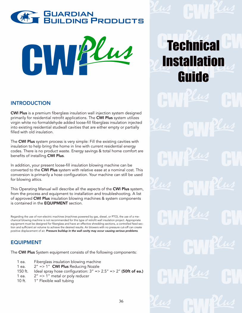
CWI Plus is a premium fiberglass insulation wall injection system designed primarily for residential retrofit applications. The CWI Plus system utilizes virgin white no formaldehyde added loose-fill fiberglass insulation injected into existing residential studwall cavities that are either empty or partially filled with old insulation. The CWI Plus system process is very simple: Fill the existing cavities with insulation to help bring the home in line with current residential energy codes. There is no product waste. Energy savings & total home comfort are benefits of installing CWI Plus. In addition, your present loose-fill insulation blowing machine can be converted to the CWI Plus system with relative ease at a nominal cost. This conversion is primarily a hose configuration. Your machine can still be used for blowing attics. This Operating Manual will describe all the aspects of the CWI Plus system, from the process and equipment to installation and troubleshooting. A list of approved CWI Plus insulation blowing machines & system components is contained in the EQUIPMENT section. Regarding the use of non-electric machines (machines powered by gas, diesel, or PTO), the use of a me-chanical blowing machine is not recommended for this type of retrofit wall insulation project. Appropriate equipment must be designed for fiberglass and have an effective shredding sections, a controlled feed sec-tion and sufficient air volume to achieve the desired results. Air blowers with no pressure cut-off can create positive displacement of air. Pressure buildup in the wall cavity may occur causing serious problems.
EQUIPMENT The CWI Plus System equipment consists of the following components: 1 ea. Fiberglass insulation blowing machine 1 ea. 2” => 1” CWI Plus Reducing Nozzle 150 ft. Ideal spray hose configuration: 3” => 2.5” => 2” (50ft of ea.) 1 ea. 2” => 1” metal or poly reducer 10 ft. 1” Flexible wall tubing
TechnicalInstallationGuide
36

Accessories
Approved Equipment List Insulation Blowing Machine .................. Source Stewart 1000, 750, 500 & 350 Series ........ InsulMaxx 5000, 4000 & 2000 ..................Spray Insulation Components
............................. Intec Corp. Krendl 1000, 1300, 2000, 2300 ................Krendl Machine Co.
Regarding the use of non-electric machines (machines powered by gas, diesel, or PTO), the use of a me-chanical blowing machine is not recommended for this type of retrofit wall insulation project. Appropriate equipment must be designed for fiberglass and have an effective shredding sections, a controlled feed sec-tion and sufficient air volume to achieve the desired results. Air blowers with no pressure cut-off can create positive displacement of air. Pressure buildup in the wall cavity may occur causing serious problems.
JOBSITE
Carefully Survey the Jobsite
Survey inside and out. This cannot be over-emphasized; shortcuts or com-placency in properly surveying the dwelling and the surrounding area can cause serious problems or damage to the residence.
2. Accurately locate problem obstacles: wiring, plumbing, gas lines,
heaters & inset medicine cabinets. These are examples, but not all the items you can encounter in the studwalls. In the stud-chases
3. Access considerations: under siding, basement floor plates, soffit, attic & interior. 4. Types of exterior finishes you will encounter: wooden clapboard,
Document
and exactly where to drill.
37
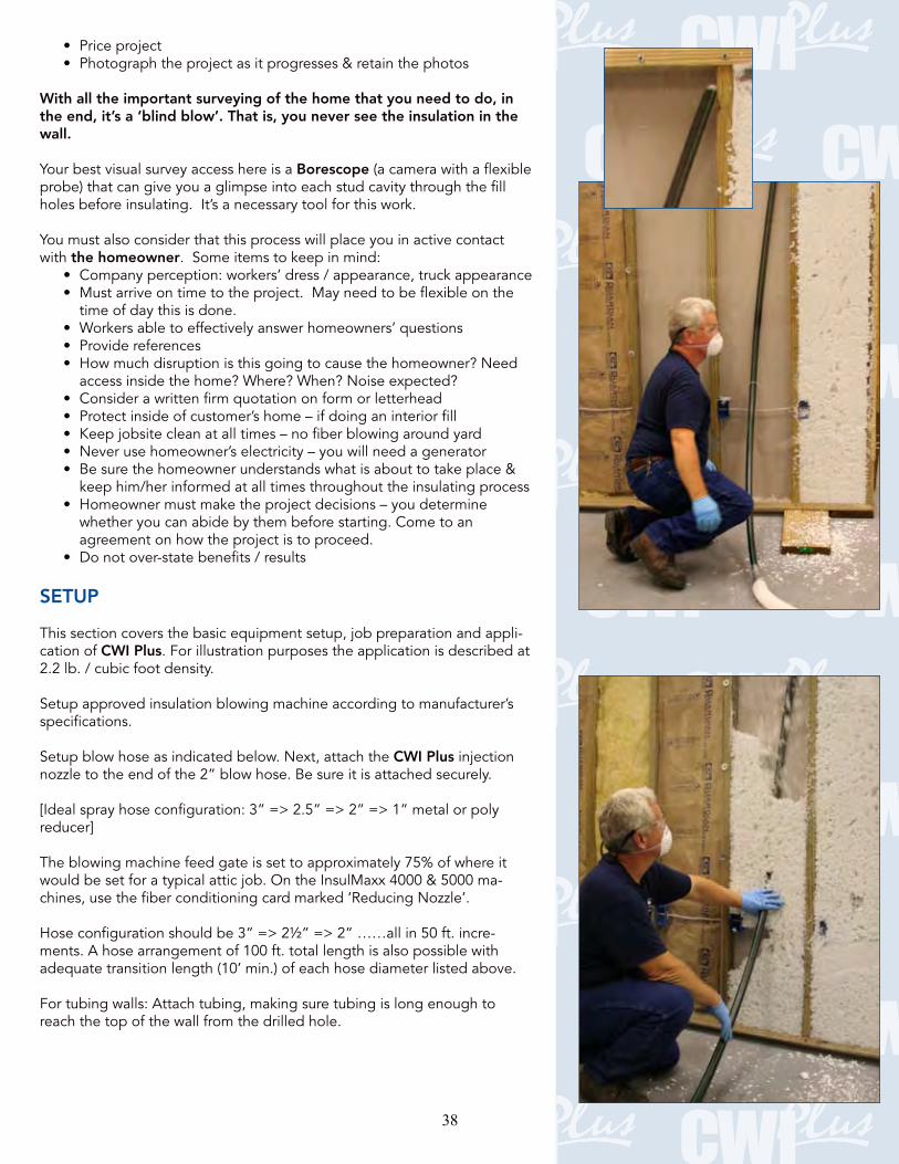
With all the important surveying of the home that you need to do, in the end, it’s a ‘blind blow’. That is, you never see the insulation in the wall.
Your best visual survey access here is a Borescope (a camera with a flexible probe) that can give you a glimpse into each stud cavity through the fill
You must also consider that this process will place you in active contact with the homeowner
time of day this is done.
whether you can abide by them before starting. Come to an agreement on how the project is to proceed.
SETUP This section covers the basic equipment setup, job preparation and appli-cation of CWI Plus. For illustration purposes the application is described at
Setup approved insulation blowing machine according to manufacturer’s specifications.
Setup blow hose as indicated below. Next, attach the CWI Plus injection
[Ideal spray hose configuration: 3” => 2.5” => 2” => 1” metal or poly reducer] The blowing machine feed gate is set to approximately 75% of where it would be set for a typical attic job. On the InsulMaxx 4000 & 5000 ma-
-ments. A hose arrangement of 100 ft. total length is also possible with adequate transition length (10’ min.) of each hose diameter listed above.
reach the top of the wall from the drilled hole.
38
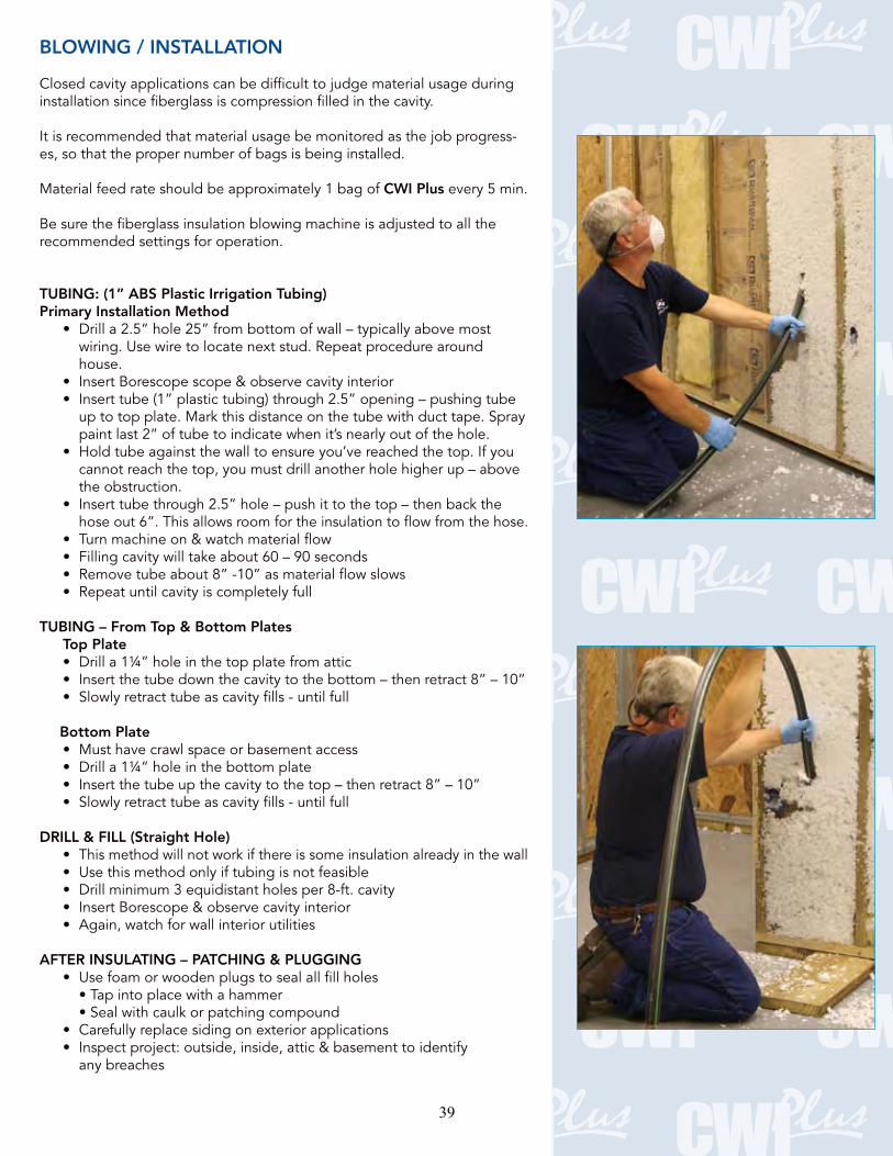
BLOWING / INSTALLATION
Closed cavity applications can be difficult to judge material usage during installation since fiberglass is compression filled in the cavity.
It is recommended that material usage be monitored as the job progress-es, so that the proper number of bags is being installed.
Material feed rate should be approximately 1 bag of CWI Plus every 5 min.
recommended settings for operation.
TUBING: (1” ABS Plastic Irrigation Tubing) Primary Installation Method
wiring. Use wire to locate next stud. Repeat procedure around house.
paint last 2” of tube to indicate when it’s nearly out of the hole.
the obstruction.
hose out 6”. This allows room for the insulation to flow from the hose.
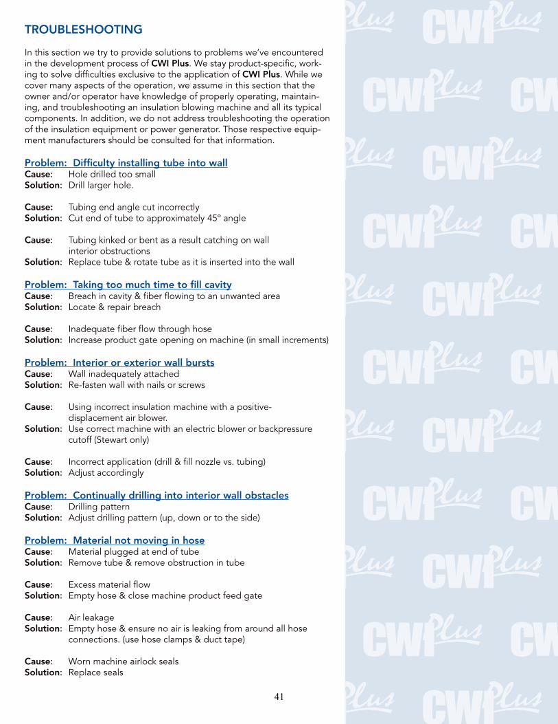
TUBING – From Top & Bottom Plates Top Plate
Bottom Plate
DRILL & FILL (Straight Hole)
AFTER INSULATING – PATCHING & PLUGGING
any breaches
39

CLEANUP
attention in various types of insulation applications. Proper presentation and complete clean-up gives a professional appearance to the job and focuses the attention of the homeowner on how good the CWI Plus proj-
Remember: Perception is reality.
CWI Plus Product & System Benefits
Product Benefits System Benefits
when compared to standard building insulation
CWI Plus complies with ASTM C 764 Type 1 requirements with includes the following test methods:
Smoke Developed < 5
40
TROUBLESHOOTING
In this section we try to provide solutions to problems we’ve encountered in the development process of CWI Plus -ing to solve difficulties exclusive to the application of CWI Pluscover many aspects of the operation, we assume in this section that the
-ing, and troubleshooting an insulation blowing machine and all its typical components. In addition, we do not address troubleshooting the operation of the insulation equipment or power generator. Those respective equip-ment manufacturers should be consulted for that information.
Problem: Difficulty installing tube into wallCause:Solution:
Cause: Tubing end angle cut incorrectlySolution: Cut end of tube to approximately 45º angle
Cause: interior obstructionsSolution: Replace tube & rotate tube as it is inserted into the wall
Problem: Taking too much time to fill cavityCause:Solution:
Cause: Inadequate fiber flow through hoseSolution: Increase product gate opening on machine (in small increments)
Problem: Interior or exterior wall burstsCause:Solution: Re-fasten wall with nails or screws
Cause: Using incorrect insulation machine with a positive- displacement air blower.Solution: cutoff (Stewart only)
Cause: Incorrect application (drill & fill nozzle vs. tubing) Solution: Adjust accordingly
Problem: Continually drilling into interior wall obstaclesCause:Solution: Adjust drilling pattern (up, down or to the side) Problem: Material not moving in hoseCause: Material plugged at end of tubeSolution: Remove tube & remove obstruction in tube
Cause: Excess material flowSolution: Empty hose & close machine product feed gate
Cause:Solution: connections. (use hose clamps & duct tape) Cause:Solution: Replace seals
41
APPENDIX
1201 Spencerville Ave.
3771 Monarch St.,
Ph: 303.466.1611 www.inteccorp.com
NN13 6FA United Kingdom
www.sprayinsulation.com Reducing Nozzle: Spray Insulation Components
This document may not be reproduced either in whole or in part without written
www.guardianbp.com42

Appendix A2.3: Guardian CWI Plus: Documentation for Weatherization / Retrofit None found.
43
Appendix A3.1: Johns Manville Spider Documentation from Material Packaging
44
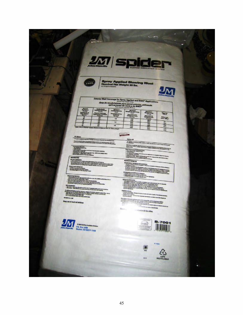
45
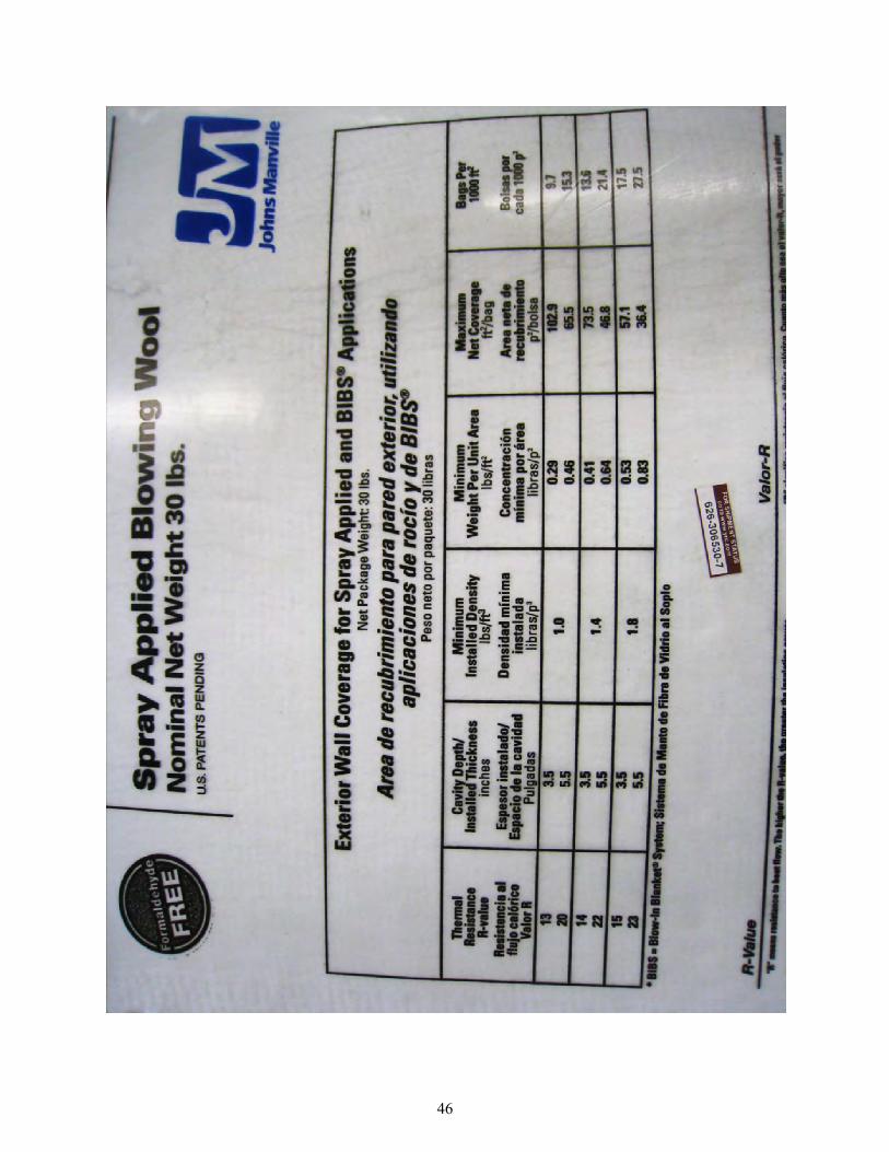
46
Appendix A3.2a: Johns Manville Spider Documentation for Dense-Packing Sell Sheet, “JM Spider Blown-In Fiber Glass”
47

“DENSE-PACK” APPLICATION JM Spider insulation offers many big advantages over cellulose in drill-and-fill applications. Incredibly easy to install, it’s convenient and saves time, while offering superior thermal and acoustical performance. JM Spider insulation also provides up to 30% better airflow resistance than cellulose when installed at recommended densities for site-built construction. Our unique design enables the fibers to more effectively fill tight spaces around pipes, wires and electrical boxes. For example, JM Spider insulation will fill 2x4 cavities up to an impressive R-15 thermal rating and 2x6 cavities up to R-24. In addition, since fiber glass is naturally mold resistant, it does not encourage the growth of mold or mildew.
WHY JM SPIDER? Small Fiber Diameter: • Superior thermal and acoustical performance• Provides higher airflow resistance vs. cellulose
Small Nodule Size: • Allows insulation to easily flow around obstacles within a wall cavity• Allows for complete and uniform cavity fill• Allows for use of small-diameter application hoses and mortar tools• Minimizes potential for equipment plugging• Won’t lose R-value due to natural convection
JM SPIDER®
BLOW-IN FIBER GLASS
PERFORMANCE ADVANTAGES • Won’t support mold growth• Won’t rot or decompose• Noncorrosive• Noncombustible• Won’t hold moisture• Won’t lose R-value with age• Primarily composed of sand, a
rapidly renewable resource
• Low dust, no itch, won’t burn skin or eyes
• Made without formaldehyde
• Works with most types of blowingmachines designed to process fiber glass insulation
• High coverage per bag
• Dry installation (no binder required)
• Uniform dense-pack cavity fill
• Won’t settle
• Contains no plastic, cardboard or other noninsulating debris
• Minimal chemical additive content; containsno acidic fire-retardant chemicals
• Safe to use and install (contact JM forFiber Glass Health Indemnity Agreement information)
• Contains at least 25% recycled glass(5% pre-consumer, 20% post-consumer)
48

Distributed by:Johns Manville Insulation Systems717 17th Street (80202)P.O. Box 5108 Denver, CO 80217-5108(800) 654-3103JM.comBIC-697 04/10 © 2010 Johns Manville. Printed in USA.
JMRE
S100
220
Printed on recycled paper.
FINER FIBER = BETTER AIRFLOW RESISTANCE, BETTER THERMAL PERFORMANCEFine-diameter JM Spider fiber creates a tortuous path for heat and airflow, resulting in high thermal and airflow resistance. JM Spider fiber is also very effective at scattering and absorbing IR radiation, which further improves R-value. Coarse-fiber cellulose has more direct airflow passages and poorer IR blocking capability, which results in less resistance to heat and airflow.
Specification Comparison JM Spider CelluloseInstalled Density, pcf* 2.2 3.5 3.7 4.0
Bag Weight, lbs 30 30 30 30
Coverage @ 3.5", ft2/bag 47 29 28 26
Advertised R-value @ 3.5" 15 13 13 13
Tested R-value @ 3.5" 15.1 12 11.9 11.7
Airflow Resistance (lb/ft2)/(ft3/s) 46 22 26 33
Air Permeance, cfm/ft2 @ 50 Pa 2.3 4.4 3.5 2.6
*The recommended installed dense-pack density for JM Spider is 2.2 pcf for drill-and-fill application. Typical installed dense-pack densities for cellulose range from 3.0 to 3.5 pcf; some weatherization agencies recommend 4.0 pcf to improve airflow resistance.
JM SPIDER FIBER GLASS COMPLIANCEASTM C764, ASTM E84, CAN/ULC S-702, CAN/ULC S-102, ULC S-129, ASTM C1149
HOW TO GET STARTED Visit specJM.com/retrofit or call (800) 654-3103 to learn more about JM Spider products, applications, training opportunities and additional resources.
JM SpiderCellulose
JM Spider vs. Cellulose “Dense-Pack”Thermal Performance
(ASTM C 518 Testing @ 3.5", 75ºF Mean)
Installed Density, Ibs/ft3
R-V
alue
16
15
14
13
12
11
101.5 2.0 2.5 3.0 3.5 4.0 4.5 5.0
ASTM C 522 Airflow Resistance @ 3.5"(50–225 Ipm flow rate per test point)
Installed Density, Ibm/ft3Air
flow
Res
ista
nce,
(Ib f
/ft2 )
/(ft
3 /s)
JM SpiderCellulose
85.0
75.0
65.0
55.0
45.0
35.0
25.0
15.0
5.01.50 1.75 2.00 2.25 2.75 3.25 3.75 4.252.50 3.00 3.50 4.00 4.50 4.75
JM SPIDER VS. DENSE-PACK CELLULOSE THERMAL PERFORMANCE (ASTM C518 Testing @ 3.5", 75ºF mean)
ASTM C 522 AIRFLOW RESISTANCE @ 3.5" DENSE-PACK APPLICATION (50–225 lpm flow rate per test point)
JM Spider has higher airflow resistance than cellulose. JM Spider provides 4.3 R-value per inch (R-15 @ 3.5").
X100 SEM PHOTOMICROGRAPHS
JM Spider Fiber Cellulose Fiber
49
Appendix A3.2b: Johns Manville Spider Documentation for Dense-Packing Spec Sheet, “Dense Pack JM Spider Insulation for Drill and Fill”
50

PERFORMANCE ADVANTAGES Improves indoor air quality – because it’s made without formaldehyde.
Energy efficient – provides superior resistance to heat transfer with R-values up to R-15 in a 2x4 cavity.
Completely fills the cavity and does not settle–the small nodules of fiber glass are resilient and do not deteriorate or lose performance with time.
Controls sound – reduces transmission of sound through exterior and interior walls and floor/ceiling assemblies. See the JM Spider insulation Acoustical Performance Advantages sheet (BID-0080) for details.
Easy to install – installs at a rate per cavity similar to dense-packed cellulose with significantly less plugging and less dust.
Mold and mildew resistant – fiber glass is naturally mold resistant.
Fire resistant and noncombustible Noncorrosive – does not accelerate corrosion of pipes, wiring or metal studs.
Durable – will not rot, mildew or otherwise deteriorate. JM Spider insulation will not hold moisture or permanently lose R-value.
Small nodule or tuft size allows the product to easily flow around obstacles, such as wiring, and through small-diameter mortar tools.
Higher installed R-value per inch vs. cellulose (typically more than 20 percent higher R value up to R-4.3 per inch).
Works with most types of blowing machines designed to process fiber glass insulation.
Provides significantly higher airflow resistance than cellulose (per ASTM C522 measurements).
Dense Pack JM Spider®
Insulation for Drill and Fill
JM FORMALDEHYDE-FREE™ FIBER GLASS INSULATIONJM Formaldehyde-free™ fiber glass building insulation offers the thermal and acoustical performance you expect from fiber glass—and it improves indoor air quality because it’s made without formaldehyde. Why is that important? Because reducing overall formaldehyde levels in the home creates a healthier living environment, and choosing JM Formaldehyde-free™ insulation is one way of achieving that goal. JM offers a complete line of Formaldehyde-free™ fiber glass building insulation. Visit specJM.com or JMhomeowner.com for more information.
PRODUCT DESCRIPTIONJM Spider insulation offers many big advantages over cellulose in drill-and-fill applications. Incredibly easy to install, it’s convenient and saves time, while offering superior thermal and acoustical performance. JM Spider insulation also provides up to 30 percent better airflow resistance than cellulose when installed at recommended densities for site-built construction. Our unique design enables the fibers to more effectively fill tight spaces around pipes, wires and electrical boxes. For example, JM Spider insulation will fill 2x4 cavities up to an impressive R-15 thermal rating and 2x6 cavities up to R-24. In addition, because fiber glass is naturally mold resistant, it does not encourage the growth of mold or mildew.
APPLICATIONSExterior Walls – Drill and fill through:
Interior Walls – Drill and fill through:
JM Spider insulation also works for weatherization of other exterior cavities such as bonus room floors, cantilevered areas and cathedral ceilings that do not require venting. For these closed cavities, follow the same installation procedures as walls. For open cavities such as floors over crawl spaces, dense pack JM Spider fiber behind netting. (For crawl space floors, be sure to consult the local code requirements for vapor retarders and contact BIBCA if you need information and training on dense packing JM Spider insulation behind netting.) It’s also a good idea to install JM Spider insulation in interior walls that contain supply plumbing and PVC waste drains to significantly reduce unwanted noise. Contact your local JM sales representative for availability of JM Spider insulation. Visit specJM.com for additional information, including information on installing.
RECOMMENDED STORAGE AND TRANSPORTStore insulation indoors. Keep insulation clean and dry at all times. When transporting, cover completely with a waterproof tarpaulin as necessary.
SPECIFICATION COMPLIANCE
Insulation.” JM Spider system meets all building code fire test requirements for concealed and exposed insulation. (See following page for a complete list of test results.)
PACKAGINGJM Spider fiber glass insulation is available in 30-lb. bags.
SHORT FORM SPECIFICATIONS All insulation shown on drawings or specified herein shall be Dense Packed JM Spider® Fiber as manufactured by Johns Manville. Thermal resistance “R” (RSI) values of the insulation shall be R (RSI) ________in ceilings, R (RSI) _________in walls and R (RSI) _________in floors over unheated spaces.
LIMITATIONS OF USE Check applicable building codes.
51
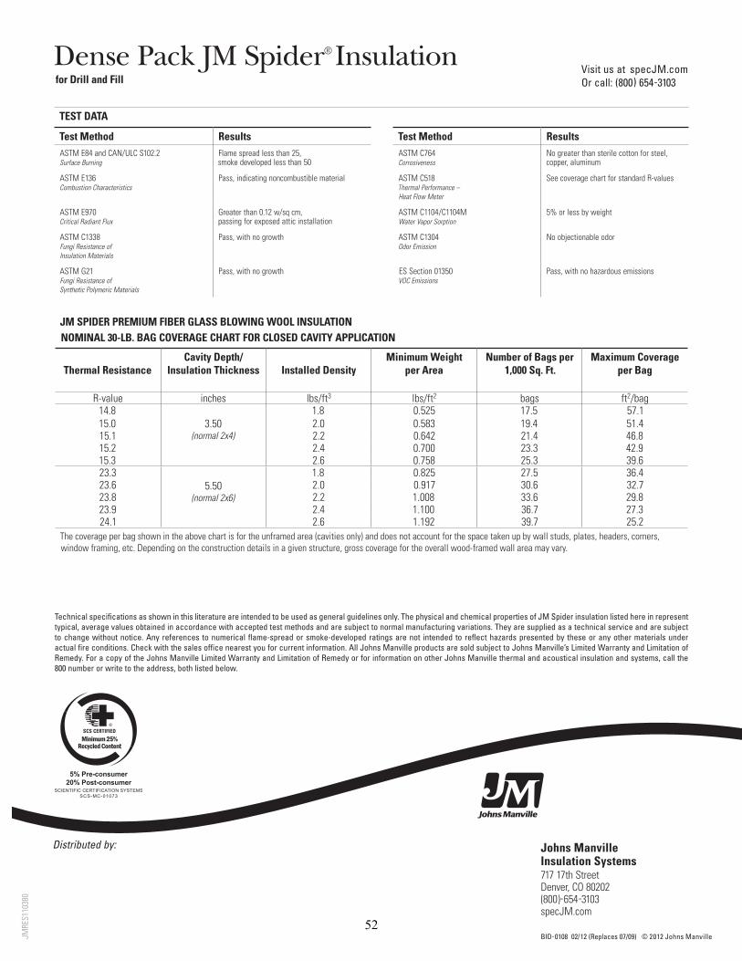
Distributed by:
a a
aa
Visit us at specJM.com Or call: (800) 654-3103
Johns Manville Insulation Systems717 17th Street Denver, CO 80202 (800)-654-3103 specJM.com
BID-0108 02/12 (Replaces 07/09) © 2012 Johns Manville
Dense Pack JM Spider® Insulationfor Drill and Fill
Technical specifications as shown in this literature are intended to be used as general guidelines only. The physical and chemical properties of JM Spider insulation listed here in represent typical, average values obtained in accordance with accepted test methods and are subject to normal manufacturing variations. They are supplied as a technical service and are subject to change without notice. Any references to numerical flame-spread or smoke-developed ratings are not intended to reflect hazards presented by these or any other materials under actual fire conditions. Check with the sales office nearest you for current information. All Johns Manville products are sold subject to Johns Manville’s Limited Warranty and Limitation of Remedy. For a copy of the Johns Manville Limited Warranty and Limitation of Remedy or for information on other Johns Manville thermal and acoustical insulation and systems, call the 800 number or write to the address, both listed below.
TEST DATA
Test Method Results Test Method ResultsASTM E84 and CAN/ Surface Burning
Flame spread less than 25, smoke developed less than 50
ASTM C764 Corrosiveness
No greater than sterile cotton for steel, copper, aluminum
ASTM E136 Combustion Characteristics
Pass, indicating noncombustible material ASTM C518 Thermal Performance – Heat Flow Meter
See coverage chart for standard R-values
ASTM E970 Critical Radiant Flux
/sq cm, passing for exposed attic installation
ASTM C1104/C1104M Water Vapor Sorption
5% or less by weight
ASTM C1338 Fungi Resistance of Insulation Materials
Pass, with no growth ASTM C1304 Odor Emission
No objectionable odor
Fungi Resistance of Synthetic Polymeric Materials
Pass, with no growth ES Section 01350 VOC Emissions
Pass, with no hazardous emissions
JM SPIDER PREMIUM FIBER GLASS BLOWING WOOL INSULATIONNOMINAL 30-LB. BAG COVERAGE CHART FOR CLOSED CAVITY APPLICATION
Thermal ResistanceCavity Depth/
Insulation Thickness Installed DensityMinimum Weight
per AreaNumber of Bags per
1,000 Sq. Ft.Maximum Coverage
per Bag
R-value inches lbs/ft3 lbs/ft2 bags ft2/bag14.8
3.50(normal 2x4)
1.8 0.525 17.5 57.115.0 2.0 0.583 19.4 51.415.1 2.2 0.642 21.4 46.815.2 2.4 0.700 23.3 42.915.3 2.6 0.758 25.3 39.623.3
5.50(normal 2x6)
1.8 0.825 27.5 36.423.6 2.0 0.917 30.6 32.723.8 2.2 1.008 33.6 29.823.9 2.4 1.100 36.7 27.324.1 2.6 1.192 39.7 25.2
The coverage per bag shown in the above chart is for the unframed area (cavities only) and does not account for the space taken up by wall studs, plates, headers, corners, window framing, etc. Depending on the construction details in a given structure, gross coverage for the overall wood-framed wall area may vary.
JMRE
S110
380
52
Appendix A3.3: Johns Manville Spider Documentation for Weatherization / Retrofit None Found.
53
Appendix A4.1: Knauf EcoFill Wx Documentation from Packaging
54
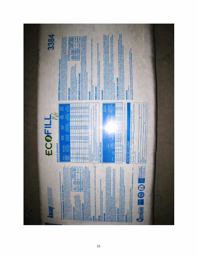
55

56
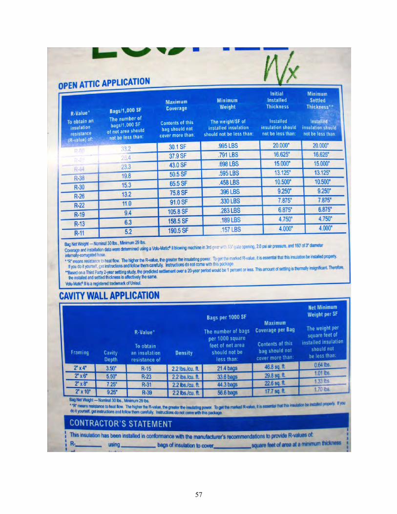
57

Appendix A4.2: Knauf EcoFill Wx Documentation for Dense-Packing Fact Sheet, “Knauf EcoFill Wx Blowing Insulation”
58
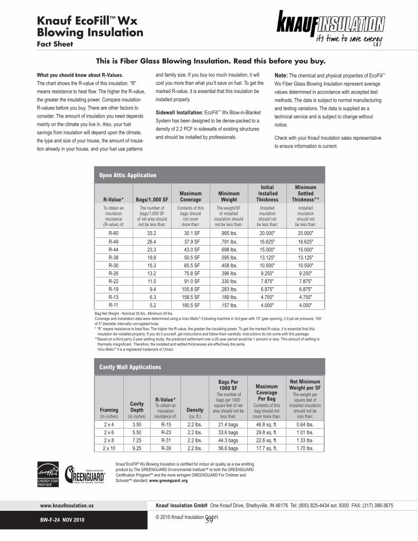
Knauf EcoFill™ WxBlowing InsulationFact Sheet
www.knaufi nsulation.us
BW-F-24 NOV 2010
Knauf Insulation GmbH One Knauf Drive, Shelbyville, IN 46176 Tel: (800) 825-4434 ext. 8300 FAX: (317) 398-3675
© 2010 Knauf Insulation GmbH.
What you should know about R-Values. The chart shows the R-value of this insulation. “R” means resistance to heat flow. The higher the R-value, the greater the insulating power. Compare insulation R-values before you buy. There are other factors to consider. The amount of insulation you need depends mainly on the climate you live in. Also, your fuel savings from insulation will depend upon the climate, the type and size of your house, the amount of insula-tion already in your house, and your fuel use patterns
and family size. If you buy too much insulation, it will cost you more than what you’ll save on fuel. To get the marked R-value, it is essential that this insulation be installed properly.
Sidewall Installation: EcoFill™ Wx Blow-in-Blanket System has been designed to be dense-packed to a density of 2.2 PCF in sidewalls of existing structures and should be installed by professionals.
Note: The chemical and physical properties of EcoFill™ Wx Fiber Glass Blowing Insulation represent average values determined in accordance with accepted test methods. The data is subject to normal manufacturing and testing variations. The data is supplied as a technical service and is subject to change without notice.
Check with your Knauf Insulation sales representative to ensure information is current.
This is Fiber Glass Blowing Insulation. Read this before you buy.
Bag Net Weight - Nominal 30 lbs., Minimum 29 lbs.Coverage and installation data were determined using a Volu-Matic® II blowing machine in 3rd gear with 13" gate opening, 2.0 psi air pressure, 150' of 3" diameter internally-corrugated hose.* “R” means resistance to heat fl ow. The higher the R-value, the greater the insulating power. To get the marked R-value, it is essential that this insulation be installed properly. If you do it yourself, get instructions and follow them carefully. Instructions do not come with this package.**Based on a third party 2-year settling study, the predicted settlement over a 20-year period would be 1 percent or less. This amount of settling is thermally insignifi cant. Therefore, the installed and settled thicknesses are effectively the same. Volu-Matic® II is a registered trademark of Unisul.
Open Attic Application
R-Value* Bags/1,000 SFMaximumCoverage
Minimum
Weight
Initial InstalledThickness
MinimumSettled
Thickness**To obtain aninsulationresistance
(R-value) of:
The number of bags/1,000 SF
of net area should not be less than:
Contents of this bags should
not covermore than:
The weight/SFof installed
insulation shouldnot be less than:
Installedinsulationshould not
be less than:
Installedinsulationshould not
be less than:
R-60 33.2 30.1 SF .995 lbs. 20.000" 20.000"R-49 26.4 37.9 SF .791 lbs. 16.625" 16.625"R-44 23.3 43.0 SF .698 lbs. 15.000" 15.000"R-38 19.8 50.5 SF .595 lbs. 13.125" 13.125"R-30 15.3 65.5 SF .458 lbs. 10.500" 10.500"R-26 13.2 75.8 SF .396 lbs. 9.250" 9.250"R-22 11.0 91.0 SF .330 lbs. 7.875" 7.875"R-19 9.4 105.8 SF .283 lbs. 6.875" 6.875"R-13 6.3 158.5 SF .189 lbs. 4.750" 4.750"R-11 5.2 190.5 SF .157 lbs. 4.000" 4.000"
Knauf EcoFill® Wx Blowing Insulation is certifi ed for indoor air quality as a low emitting product by The GREENGUARD Environmental Institute™ to both the GREENGUARD Certifi cation ProgramSM and the more stringent GREENGUARD For Children and Schools™ standard. www.greenguard.org
Framing(in inches)
Cavity Depth
(in inches)
R-Value*To obtain an insulation
resistance of:
Density
(cu. ft.)
Bags Per 1000 SF
The number of bags per 1000
square feet of net area should not be
less than:
Maximum Coverage Per Bag
Contents of this bag should not
cover more than:
Net Minimum Weight per SF
The weight per square feet of
installed insulation should not be
less than:
2 x 4 3.50 R-15 2.2 lbs. 21.4 bags 46.8 sq. ft. 0.64 lbs.2 x 6 5.50 R-23 2.2 lbs. 33.6 bags 29.8 sq. ft. 1.01 lbs.2 x 8 7.25 R-31 2.2 lbs. 44.3 bags 22.6 sq. ft. 1.33 lbs.
2 x 10 9.25 R-39 2.2 lbs. 56.6 bags 17.7 sq. ft. 1.70 lbs.
Cavity Wall Applications
59

Appendix A4.3: Knauf EcoFill Wx Documentation for Weatherization / Retrofit Data Sheet, “EcoFill Wx Glasswool Blowing Insulation for Weatherizing Attics and Sidewalls”
60
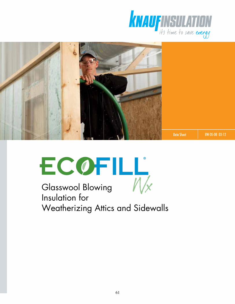
Data Sheet BW-DS-08 03-12
Glasswool Blowing Insulation for Weatherizing Attics and Sidewalls
®
61

EcoFill® Wx Glasswool Insulation for Weatherizing Attics and Sidewalls
Description.QDXI,QVXODWLRQ(FR)LOO:[*ODVVZRRO%ORZLQJ,QVXODWLRQLVDQXQERQGHGYLUJLQILEURXVJODVVEORZLQJLQVXODWLRQKDYLQJDKLJKGHJUHHRISRVWFRQVXPHUUHF\FOHGFRQWHQWGHVLJQHGIRUZHDWKHUL]LQJDQGUHWURILWWLQJH[LVWLQJKRXVLQJ
Application.QDXI,QVXODWLRQ(FR)LOO:[ *ODVVZRRO%ORZLQJ,QVXODWLRQLVXVHGWRGHQVHSDFNVLGHZDOOVXVLQJWKHGULOODQGILOOWHFKQLTXHFRPPRQLQUHWURILWWLQJKRPHVRULQKRPHZHDWKHUL]DWLRQDFWLYLWLHV(FR)LOO:[LVDOVRH[FHOOHQWIRUGRLQJRSHQEORZVLQDWWLFV7KLVPHDQVWKDWRQO\RQHSURGXFWLVQHHGHGWRFRPSOHWHDQLQVXOD-WLRQUHWURILWZHDWKHUL]DWLRQSURMHFW
Features and BenefitsExcellent Thermal Properties for Sidewalls: )LOOVDOOJDSVDQGYRLGVLQZDOOFDYLWLHVFUHDWLQJD
WKHUPDOEDUULHUDJDLQVWRXWVLGHDLUDQGEHWWHU WHPSHUDWXUHFRQWURO +DVJUHDWHUUHVLVWDQFHWRDLULQILOWUDWLRQWKDQ FHOOXORVLFPDWHULDOV 5HVLVWVKHDWIORZZLWKDQ5YDOXHRI5
LQ[FRQVWUXFWLRQ 5HVLVWVKHDWIORZZLWKDQ5YDOXHRI5
LQ[FRQVWUXFWLRQ $EVROXWHO\ZLOOQRWVHWWOHLQZDOOVAnd Attics: :LOOQRWFKDQJHIURPLWVLQWHQGHG5YDOXHRYHULWV
OLIHWLPH
Saves Warehouse Space (FR)LOO:[UHTXLUHVDERXWRQHKDOIRIWKHZDUH-
KRXVHVSDFHRIFRPSHWLQJFHOOXORVLFSURGXFWV 7ZLFHDVPDQ\MREVFDQEHORDGHGRQDWUXFNZKHQ
(FR)LOO:[LVXVHGLQVWHDGRIFHOOXORVLFSURGXFWV
Better Coverage than Cellulose 0RUHWKDQ[WKHFRYHUDJHSHUEDJSustainability UHF\FOHGSRVWFRQVXPHUJODVVFRQWHQWDQG
8/(YHULILFDWLRQHYHU\PRQWKV (DFKEDJFRQWDLQVWKHHTXLYDOHQWRIUHF\FOHG
ERWWOHVImproves Crew Productivity :LWK(FR)LOO:[LQVWDOOHUVVSHQGOHVVWLPHKDQ-
GOLQJEDJV ,QDVTXDUHIRRWKRPHDERXWEDJVRI
(FR)LOO:[DUHUHTXLUHGFRPSDUHGWREDJVRIFHOOXORVLFPDWHULDO
,QVWDOOVFOHDQHUWKDQFHOOXORVHYLUWXDOO\GXVWIUHH %ORZVFOHDQDQGVPRRWKDQGGRHVQRWUHTXLUH
VWDELOL]LQJ
Strong Poly Bag Packaging (FR)LOO:[LVSDFNDJHGLQDYHU\VWURQJSRO\EDJ
WKDWSUHYHQWVEDJEUHDNDJHDQGMREVLWHVSLOODJH7KHEDJVVWDFNZHOODQGKDYHDFRHIILFLHQWRIIULF-WLRQVXIILFLHQWWRUHGXFHVOLSSDJH
Indoor Air Quality &HUWLILHGIRULQGRRUDLUTXDOLW\DVDORZHPLWWLQJ
SURGXFWE\7KH*5((1*8$5'(QYLURQPHQWDO,QVWLWXWHWRERWKWKH*5((1*8$5',QGRRU$LU4XDOLW\&HUWLILFDWLRQ3URJUDP60DQGWKHPRUHVWULQ-JHQW*5((1*8$5'&KLOGUHQ6FKRROVVWDQGDUGDQGLVYHULILHGWREHIRUPDOGHK\GHIUHH
Non-combustible *ODVVILEHULVQDWXUDOO\QRQFRPEXVWLEOHDQG UHPDLQVVRIRUWKHOLIHRIWKHSURGXFW8QOLNHFHOOX-
ORVH(FR)LOO:[UHTXLUHVQRDGGLWLRQDOILUHUHWDUGDQWFKHPLFDOWUHDWPHQWV8QIDFHGILEHUJODVVLQVXODWLRQLVUHFRJQL]HGE\EXLOGLQJFRGHJURXSVDVDQDFFHSW-DEOHILUHVWRSLQUHVLGHQWLDOZRRGIUDPHZDOOV
Resists Microbial Growth 'RHVQRWSURPRWHWKHJURZWKRIIXQJLRUEDFWHULD :LOOQRWURWRUVXVWDLQYHUPLQURGHQWVRULQVHFWVSpecification Compliance $670&7\SH, ++,%&ODVV% *5((1*8$5',QGRRU$LU4XDOLW\&HUWLILHG®
*5((1*8$5'&KLOGUHQDQG6FKRROV&HUWLILHG60
.QDXI,QVXODWLRQ(FR)LOO:[*ODVVZRRO%ORZLQJ,QVXODWLRQLVPDQXIDFWXUHGZLWKDPLQLPXPRISRVWFRQVXPHUUHF\FOHGJODVV
0HHWVWKH4XDOLW\6WDQGDUGVRIWKH6WDWHRI&DOLIRUQLD
Technical DataAir Infiltration Resistance :KHQWHVWHGDJDLQVWWKUHHFHOOXORVHSURGXFWV XVLQJ$670&(FR)LOO:[VKRZHGWR EHWWHUDLUIORZUHVLVWDQFHWKDQWKUHHOHDGLQJ EUDQGV6HH7DEOHULJKWNoise Reduction ,PSURYHV6RXQG7UDQVPLVVLRQ&ODVV67&UDWLQJV
E\WRSRLQWV $SRLQW67&FKDQJHLVDQRWLFHDEOHLPSURYHPHQW
Surface Burning Characteristics 'RHVQRWH[FHHG)ODPH6SUHDG6PRNH
'HYHORSHGZKHQWHVWHGLQDFFRUGDQFHZLWK$670(DQG&$18/&60
Critical Radiant Flux (ASTM E 970) *UHDWHUWKDQ:FP2.
Moisture Vapor Sorption (ASTM C 1104) PD[LPXPE\ZHLJKW
Corrosion (ASTM C 764) 1RJUHDWHUWKDQVWHULOHFRWWRQ :LOOQRWDFFHOHUDWHFRUURVLRQRIDOXPLQXPVWHHO RUFRSSHUMicrobial Growth (ASTM C 1338) 'RHVQRWVXSSRUWPLFURELDOJURZWK
Non-Combustibility (ASTM E 136) 1RWHPSHUDWXUHULVHDERYH)&
Thermal Performance7KHVWDWHGWKHUPDOSHUIRUPDQFHRI(FR)LOO:[%ORZLQJ,QVXODWLRQUHTXLUHVLQVWDOODWLRQLQDFFRUGDQFHZLWKWKHPDQXIDFWXUHU¶VLQVWUXFWLRQV)DLOXUHWRLQVWDOOWKHPDWHULDOSURSHUO\ZLOOLPSDFWWKHSHUIRUPDQFHRIWKLVSURGXFW7KLVSURGXFWPXVWEHLQVWDOOHGDFFRUGLQJWRWKH
62
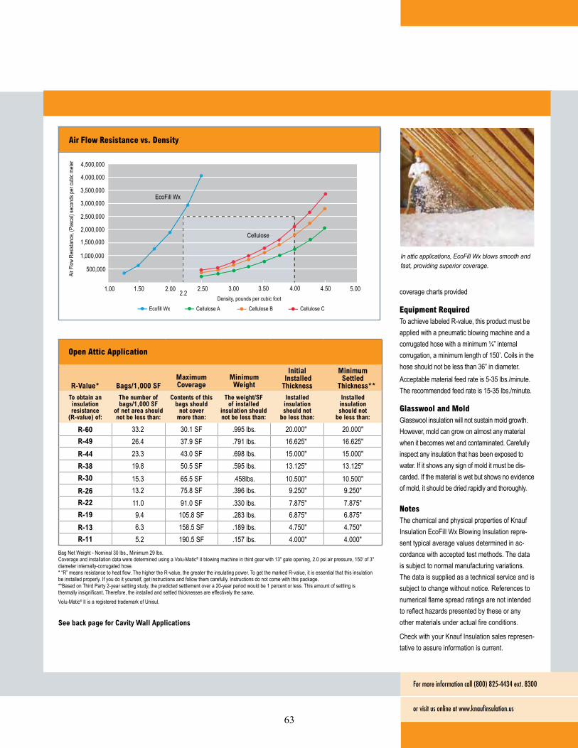
EcoFill® Wx Glasswool Insulation for Weatherizing Attics and Sidewalls
FRYHUDJHFKDUWVSURYLGHG
Equipment Required7RDFKLHYHODEHOHG5YDOXHWKLVSURGXFWPXVWEHDSSOLHGZLWKDSQHXPDWLFEORZLQJPDFKLQHDQGDFRUUXJDWHGKRVHZLWKDPLQLPXPó´LQWHUQDOFRUUXJDWLRQDPLQLPXPOHQJWKRI¶&RLOVLQWKHKRVHVKRXOGQRWEHOHVVWKDQ´LQGLDPHWHU$FFHSWDEOHPDWHULDOIHHGUDWHLVOEVPLQXWH7KHUHFRPPHQGHGIHHGUDWHLVOEVPLQXWH
Glasswool and Mold*ODVVZRROLQVXODWLRQZLOOQRWVXVWDLQPROGJURZWK+RZHYHUPROGFDQJURZRQDOPRVWDQ\PDWHULDOZKHQLWEHFRPHVZHWDQGFRQWDPLQDWHG&DUHIXOO\LQVSHFWDQ\LQVXODWLRQWKDWKDVEHHQH[SRVHGWRZDWHU,ILWVKRZVDQ\VLJQRIPROGLWPXVWEHGLV-FDUGHG,IWKHPDWHULDOLVZHWEXWVKRZVQRHYLGHQFHRIPROGLWVKRXOGEHGULHGUDSLGO\DQGWKRURXJKO\
Notes7KHFKHPLFDODQGSK\VLFDOSURSHUWLHVRI.QDXI,QVXODWLRQ(FR)LOO:[%ORZLQJ,QVXODWLRQUHSUH-VHQWW\SLFDODYHUDJHYDOXHVGHWHUPLQHGLQDF-FRUGDQFHZLWKDFFHSWHGWHVWPHWKRGV7KHGDWDLVVXEMHFWWRQRUPDOPDQXIDFWXULQJYDULDWLRQV7KHGDWDLVVXSSOLHGDVDWHFKQLFDOVHUYLFHDQGLVVXEMHFWWRFKDQJHZLWKRXWQRWLFH5HIHUHQFHVWRQXPHULFDOIODPHVSUHDGUDWLQJVDUHQRWLQWHQGHGWRUHIOHFWKD]DUGVSUHVHQWHGE\WKHVHRUDQ\RWKHUPDWHULDOVXQGHUDFWXDOILUHFRQGLWLRQV
&KHFNZLWK\RXU.QDXI,QVXODWLRQVDOHVUHSUHVHQ-WDWLYHWRDVVXUHLQIRUPDWLRQLVFXUUHQW
For more information call (800) 825-4434 ext. 8300
or visit us online at www.knaufinsulation.us
%DJ1HW:HLJKW1RPLQDOOEV0LQLPXPOEV&RYHUDJHDQGLQVWDOODWLRQGDWDZHUHGHWHUPLQHGXVLQJD9ROX0DWLF®,,EORZLQJPDFKLQHLQWKLUGJHDUZLWKJDWHRSHQLQJSVLDLUSUHVVXUHRIGLDPHWHULQWHUQDOO\FRUUXJDWHGKRVH ³5´PHDQVUHVLVWDQFHWRKHDWIORZ7KHKLJKHUWKH5YDOXHWKHJUHDWHUWKHLQVXODWLQJSRZHU7RJHWWKHPDUNHG5YDOXHLWLVHVVHQWLDOWKDWWKLVLQVXODWLRQEHLQVWDOOHGSURSHUO\,I\RXGRLW\RXUVHOIJHWLQVWUXFWLRQVDQGIROORZWKHPFDUHIXOO\,QVWUXFWLRQVGRQRWFRPHZLWKWKLVSDFNDJH %DVHGRQ7KLUG3DUW\\HDUVHWWOLQJVWXG\WKHSUHGLFWHGVHWWOHPHQWRYHUD\HDUSHULRGZRXOGEHSHUFHQWRUOHVV7KLVDPRXQWRIVHWWOLQJLVWKHUPDOO\LQVLJQLILFDQW7KHUHIRUHWKHLQVWDOOHGDQGVHWWOHGWKLFNQHVVHVDUHHIIHFWLYHO\WKHVDPH9ROX0DWLF®,,LVDUHJLVWHUHGWUDGHPDUNRI8QLVXO
R-Value* Bags/1,000 SFMaximumCoverage
Minimum
Weight
Initial InstalledThickness
MinimumSettled
Thickness**To obtain aninsulationresistance
(R-value) of:
The number of bags/1,000 SF
of net area should not be less than:
Contents of this bags should
not covermore than:
The weight/SFof installed
insulation shouldnot be less than:
Installedinsulationshould not
be less than:
Installedinsulationshould not
be less than:
R-60 33.2 6) OEV R-49 6) OEV R-44 23.3 6) OEV R-38 6) OEV R-30 15.3 6) OEV R-26 13.2 6) OEV R-22 11.0 6) OEV R-19 6) OEV R-13 6) OEV R-11 5.2 6) OEV
Open Attic Application
In attic applications, EcoFill Wx blows smooth and fast, providing superior coverage.
Air Flow Resistance vs. Density
500,000
1,000,000
1,500,000
2,000,000
2,500,000
3,000,000
3,500,000
4,000,000
4,500,000
1.00 1.50 2.00 2.50 3.00 3.50 4.00 4.50 5.002.2
EcoFill Wx
Cellulose
Air F
low R
esist
ance
, (Pa
scal)
seco
nds p
er cu
bic m
eter
Density, pounds per cubic footEcofill Wx Cellulose A Cellulose B Cellulose C
See back page for Cavity Wall Applications
63
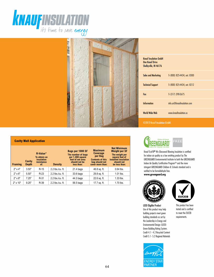
Knauf EcoFill® Wx Glasswool Blowing Insulation is certified for indoor air quality as a low emitting product by The GREENGUARD Environmental Institute to both the GREENGUARD Indoor Air Quality Certification ProgramSM and the more stringent GREENGUARD Children & Schools standard and is verified to be formaldehyde free. www.greenguard.org
Knauf Insulation GmbH One Knauf DriveShelbyville, IN 46176
Sales and Marketing 1-(800) 825-4434, ext. 8300
Technical Support 1-(800) 825-4434, ext. 8212
Fax 1-(317) 398-3675
Information [email protected]
World Wide Web www.knaufinsulation.us
©2012 Knauf Insulation GmbH.
Cavity Wall Application
FramingCavity Depth
R-Value*To obtain an insulation resistance
of: Density
Bags per 1000 SFThe number of bags
per 1,000 square feet of net area should not be
less than:
Maximum Coverage per Bag
Contents of this bag should not
cover more than:
Net Minimum Weight per SFThe weight per square feet of
installed insulation should not
be less than:
Ǝ[Ǝ Ǝ R-15 OEVFXIW EDJV VTIW OEVƎ[Ǝ Ǝ R-23 OEVFXIW EDJV VTIW OEVƎ[Ǝ Ǝ R-31 OEVFXIW EDJV VTIW OEVƎ[Ǝ Ǝ R-39 OEVFXIW EDJV VTIW OEV
LEED Eligible Product Use of this product may help building projects meet green building standards as set by the Leadership in Energy and Environmental Design (LEED) Green Building Rating System. Credit 4.1 - 4.2 Recycled Content Credit 5.1 - 5.2 Regional Materials
This product has been tested and is certified to meet the EUCEB requirements.
64

Appendix A5.1: Owens Corning ProPink L77 Documentation on Material Packaging
65
66

67

Appendix A5.2a: Owens Corning ProPink L77 Documentation for Dense-Packing Brochure, “Introducing ProPink L77 Loosefill Insulation”
68
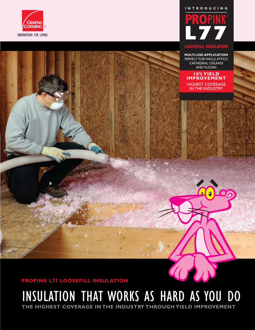
HIGH PERFORMANCE FIBERIZING TECHNOLOGYOwens Corning developed a new fiber which when blown creates a effectively distributed network of thermal reservoirs to resist heat transfer. This High Performance Fiberizing Technology produces a fiber construction that achieves a higher thermal performance in blown applications.
PROPRIETARY MANUFACTURING PROCESSTo produce PROPINK® L77 LooseFill Insulation, Owens Corning developed a proprietary manufacturing process specifically for loosefill products. This new process resulted in a yield improvement of 18% in terms of product performance.
VERSATILE MULTI-USE APPLICATION PROPINK® L77 LooseFill Insulation has been designed for use in walls, attics, cathedral ceilings and floors.
AIR INFILTRATION IN WALLSPROPINK® L77 LooseFill Insulation also offers exceptional performance for air-infiltration control and thermal protection.
Easily installed in walls and improved nesting for compaction
Can now be “dense packed” into walls at an installed density of up to 2.50 pounds per cubic foot*
Achieves an airflow reduction equal to cellulose, while providing R-Value greater than cellulose**
PROPINK® L77 LooseFill Insulation exhibits unsurpassed versatility—for installation, flexibility, performance, and productivity.
WHY PINK IS GREEN™
By delivering solutions that conserve energy and protect the environment, Owens Corning is helping make the world a better place, one community at a time. We manufacture building materials that save energy, reduce reliance on fossil fuels and decrease greenhouse gas emissions around the world.
OWENS CORNING INSULATING SYSTEMS, LLCONE OWENS CORNING PARKWAYTOLEDO, OHIO, USA 43659
1-800-GET-PINK®
www.owenscorning.comPROPINK L77 LOOSEFILL INSULATION
THE HIGHEST COVERAGE IN THE INDUSTRY THROUGH YIELD IMPROVEMENT
A new High Performance Fiberizing Technology boasts effectively distributed thermal reservoirs (see above) to achieve and maintain industry-standard
thermal requirements with less glass material (see below).
INTRODUCINGPROPINK® L77 LOOSEFILL INSULATIONLeave it to Owens Corning, the pioneer of fiberglass, to create a new fiber, loosefill product and manufacturing process that is so efficient and versatile, it is revolutionizing the industry. No other loosefill insulation measures up to its coverage, performance and energy-efficiency. PROPINK® L77 LooseFill Insulation leads the industry in thermal performance and yield.
OLDER FIBERS NEW HIGH PERFORMANCE FIBERIZING TECHNOLOGY
PROPINK® L77 LOOSEFILL INSULATION blows faster, is more energy-efficient, covers more square footage per bag, and can be used for multiple applications.
INSULATION THAT WORKS AS HARD AS YOU DO
PROPINK® L77 INSULATION APPLICATION CHARTS(information applies to new construction and retrofit applications.) (NOMINAL BAG WEIGHT 33 LBS)
This product shows virtually no settling. This information applies to new con-struction and retro applications. Unisol Volu-Matic III machine was used to deter-mine the coverage information above. The machine was set up in 3rd gear, with a 75% open gate and a 3” hose, blowing the wool out in a 10 ft. arc.
R-VALUE BAGS PER 1000 SQ. FT.
MAX NET COVERAGE
MIN WT/SQ. FT.
MINIMUM THICKNESS
(IN)
MINIMUM SETTLED
THICKNESS(IN)
R-13 5.5 182.9 0.180 4.75 4.75R-19 8.1 124.2 0.266 6.75 6.75R-22 9.4 106.3 0.311 7.75 7.75R-26 11.2 89.6 0.368 9.00 9.00R-30 13.0 77.0 0.428 10.25 10.25R-38 16.8 59.5 0.555 12.75 12.75R-44 20.1 49.8 0.662 14.75 14.75R-49 22.6 44.2 0.747 16.25 16.25R-60 28.5 35.1 0.940 19.50 19.50
ATTICS
R-VALUE MINIMUM THICKNESS
INSTALLED DENSITYLBS. PER CU. FT.
MAXIMUM COVERAGE
PER BAG
BAGS PER1000 SQ. FT.
MINIMUM WEIGHT LBS.
PER SQ. FT.
R-13 3.5 (2X4) 1.3 87.0 11.5 0.379
R-15 3.5 (2X4) 1.5 75.4 13.3 0.438
R-21 5.5 (2X6) 1.3 55.4 18.1 0.596
R-24 5.5 (2X6) 1.8 40.0 25.0 0.825
R-VALUE MINIMUM THICKNESS
INSTALLED DENSITYLBS. PER CU. FT.
MAXIMUM COVERAGE
PER BAG
BAGS PER1000 SQ. FT.
MINIMUM WEIGHT LBS.
PER SQ. FT.
R-28 2X8 1.3 42.0 23.8 0.785
R-36 2X10 1.3 32.9 30.4 1.002
R-44 2X12 1.3 27.1 36.9 1.219
R-VALUE MINIMUM THICKNESS
INSTALLED DENSITYLBS. PER CU. FT.
MAXIMUM COVERAGE
PER BAG
BAGS PER1000 SQ. FT.
MINIMUM WEIGHT LBS.
PER SQ. FT.
R-31 2X8 1.4 39.0 25.6 0.846
R-39 2X10 1.4 30.6 32.7 1.079
R-48 2X12 1.5 23.5 42.6 1.406
WALLS
CATHEDRAL CEILINGSFLOORS
INCHES OF INSULATION TO ACHIEVE R-30
AIR FLOWREDUCTION (%)
INSTALLED R-VALUE (2X4 WALL CAVITY)
PROPINKL77
2.5 pct
CELLULOSE
3.7 pct
49% 1649%
12.6PROPINK
L77
2.5 pct
CELLULOSE
3.7pct
PROPINK®
L77LOOSEFILL INSULATION
MULTI-USE APPLICATION PERFECT FOR WALLS, ATTICS,
CATHEDRAL CEILINGS AND FLOORS
I N T R O D U C I N G
18% YIELD IMPROVEMENT HIGHEST COVERAGE
IN THE INDUSTRY
10
11
9
12
PROPINKL77
JETSTREAM73.31
CLIMATE PRO
ATTIC GUARD
PROPINKRED BAG
INSULSAFE SP
10.25"
11.5"
10.38"
11.75"12.40"
10.88"
Source: Comparative Study on Air Infiltration by NAHB Research Center, 10/09
PROPINK® L77 Loosefill Insulation carries the GREENGUARD® Certification, an industry independent, third-party testing program for low emitting products and materials. In fact, Owens Corning was the first insulation manufacturer to qualify for the stringent GREENGUARD® Product Emission Standard for Children and Schools.
Owens Corning is the first insulation and masonry veneer manufacturer to receive NAHB Research Center GREEN certification which helps builders and designers select products that meet specific green practices and can earn points towards the National Green Building Standard.
Owens Corning glass fiber and foam products made in North America are certified for their recycled content by Scientific Certification Systems (SCS). Our glass fiber products use an average of 50% recycled glass content, and our rigid foam insulation uses an average of 20% recycled content, with all foam scrap recycled back into the process instead of going to landfills
Owens Corning is an ENERGY STAR Partner. ENER-GY STAR is a joint program of the U.S. Environmental Protection Agency and the U.S. Department of Energy helping us all save money and protect the environ-ment through energy efficient products and practices.
MBDC Cradle-to-Cradle CertifiedCM PROPINK® L77 Loosefill Insulation at the Silver level. This certification means a product meets criteria in a number of areas which include: safe and healthy materials; design for reutilization (e.g. recycling); energy efficiency; efficient water consumption and the deployment of socially responsible strategies..
Printed in U.S.A. May 2011. THE PINK PANTHER & © 1964–2011 Metro-Goldwyn-Mayer Studios Inc. All Rights Reserved. The color PINK is a registered trademark of Owens Corning. ©2011 Owens Corning.
Energy Star and the Energy Star logo are registered trademarks of the Environmental Protection Agency. The GREENGUARD INDOOR AIR QUALITY CERTIFIED Mark is a registered certification mark used under license through GREENGUARD Environmental Institute. Patents Pending 69

HIGH PERFORMANCE FIBERIZING TECHNOLOGYOwens Corning developed a new fiber which when blown creates a effectively distributed network of thermal reservoirs to resist heat transfer. This High Performance Fiberizing Technology produces a fiber construction that achieves a higher thermal performance in blown applications.
PROPRIETARY MANUFACTURING PROCESSTo produce PROPINK® L77 LooseFill Insulation, Owens Corning developed a proprietary manufacturing process specifically for loosefill products. This new process resulted in a yield improvement of 18% in terms of product performance.
VERSATILE MULTI-USE APPLICATION PROPINK® L77 LooseFill Insulation has been designed for use in walls, attics, cathedral ceilings and floors.
AIR INFILTRATION IN WALLSPROPINK® L77 LooseFill Insulation also offers exceptional performance for air-infiltration control and thermal protection.
Easily installed in walls and improved nesting for compaction
Can now be “dense packed” into walls at an installed density of up to 2.50 pounds per cubic foot*
Achieves an airflow reduction equal to cellulose, while providing R-Value greater than cellulose**
PROPINK® L77 LooseFill Insulation exhibits unsurpassed versatility—for installation, flexibility, performance, and productivity.
WHY PINK IS GREEN™
By delivering solutions that conserve energy and protect the environment, Owens Corning is helping make the world a better place, one community at a time. We manufacture building materials that save energy, reduce reliance on fossil fuels and decrease greenhouse gas emissions around the world.
OWENS CORNING INSULATING SYSTEMS, LLCONE OWENS CORNING PARKWAYTOLEDO, OHIO, USA 43659
1-800-GET-PINK®
www.owenscorning.comPROPINK L77 LOOSEFILL INSULATION
THE HIGHEST COVERAGE IN THE INDUSTRY THROUGH YIELD IMPROVEMENT
A new High Performance Fiberizing Technology boasts effectively distributed thermal reservoirs (see above) to achieve and maintain industry-standard
thermal requirements with less glass material (see below).
INTRODUCINGPROPINK® L77 LOOSEFILL INSULATIONLeave it to Owens Corning, the pioneer of fiberglass, to create a new fiber, loosefill product and manufacturing process that is so efficient and versatile, it is revolutionizing the industry. No other loosefill insulation measures up to its coverage, performance and energy-efficiency. PROPINK® L77 LooseFill Insulation leads the industry in thermal performance and yield.
OLDER FIBERS NEW HIGH PERFORMANCE FIBERIZING TECHNOLOGY
PROPINK® L77 LOOSEFILL INSULATION blows faster, is more energy-efficient, covers more square footage per bag, and can be used for multiple applications.
INSULATION THAT WORKS AS HARD AS YOU DO
PROPINK® L77 INSULATION APPLICATION CHARTS(information applies to new construction and retrofit applications.) (NOMINAL BAG WEIGHT 33 LBS)
This product shows virtually no settling. This information applies to new con-struction and retro applications. Unisol Volu-Matic III machine was used to deter-mine the coverage information above. The machine was set up in 3rd gear, with a 75% open gate and a 3” hose, blowing the wool out in a 10 ft. arc.
R-VALUE BAGS PER 1000 SQ. FT.
MAX NET COVERAGE
MIN WT/SQ. FT.
MINIMUM THICKNESS
(IN)
MINIMUM SETTLED
THICKNESS(IN)
R-13 5.5 182.9 0.180 4.75 4.75R-19 8.1 124.2 0.266 6.75 6.75R-22 9.4 106.3 0.311 7.75 7.75R-26 11.2 89.6 0.368 9.00 9.00R-30 13.0 77.0 0.428 10.25 10.25R-38 16.8 59.5 0.555 12.75 12.75R-44 20.1 49.8 0.662 14.75 14.75R-49 22.6 44.2 0.747 16.25 16.25R-60 28.5 35.1 0.940 19.50 19.50
ATTICS
R-VALUE MINIMUM THICKNESS
INSTALLED DENSITYLBS. PER CU. FT.
MAXIMUM COVERAGE
PER BAG
BAGS PER1000 SQ. FT.
MINIMUM WEIGHT LBS.
PER SQ. FT.
R-13 3.5 (2X4) 1.3 87.0 11.5 0.379
R-15 3.5 (2X4) 1.5 75.4 13.3 0.438
R-21 5.5 (2X6) 1.3 55.4 18.1 0.596
R-24 5.5 (2X6) 1.8 40.0 25.0 0.825
R-VALUE MINIMUM THICKNESS
INSTALLED DENSITYLBS. PER CU. FT.
MAXIMUM COVERAGE
PER BAG
BAGS PER1000 SQ. FT.
MINIMUM WEIGHT LBS.
PER SQ. FT.
R-28 2X8 1.3 42.0 23.8 0.785
R-36 2X10 1.3 32.9 30.4 1.002
R-44 2X12 1.3 27.1 36.9 1.219
R-VALUE MINIMUM THICKNESS
INSTALLED DENSITYLBS. PER CU. FT.
MAXIMUM COVERAGE
PER BAG
BAGS PER1000 SQ. FT.
MINIMUM WEIGHT LBS.
PER SQ. FT.
R-31 2X8 1.4 39.0 25.6 0.846
R-39 2X10 1.4 30.6 32.7 1.079
R-48 2X12 1.5 23.5 42.6 1.406
WALLS
CATHEDRAL CEILINGSFLOORS
INCHES OF INSULATION TO ACHIEVE R-30
AIR FLOWREDUCTION (%)
INSTALLED R-VALUE (2X4 WALL CAVITY)
PROPINKL77
2.5 pct
CELLULOSE
3.7 pct
49% 1649%
12.6PROPINK
L77
2.5 pct
CELLULOSE
3.7pct
PROPINK®
L77LOOSEFILL INSULATION
MULTI-USE APPLICATION PERFECT FOR WALLS, ATTICS,
CATHEDRAL CEILINGS AND FLOORS
I N T R O D U C I N G
18% YIELD IMPROVEMENT HIGHEST COVERAGE
IN THE INDUSTRY
10
11
9
12
PROPINKL77
JETSTREAM73.31
CLIMATE PRO
ATTIC GUARD
PROPINKRED BAG
INSULSAFE SP
10.25"
11.5"
10.38"
11.75"12.40"
10.88"
Source: Comparative Study on Air Infiltration by NAHB Research Center, 10/09
PROPINK® L77 Loosefill Insulation carries the GREENGUARD® Certification, an industry independent, third-party testing program for low emitting products and materials. In fact, Owens Corning was the first insulation manufacturer to qualify for the stringent GREENGUARD® Product Emission Standard for Children and Schools.
Owens Corning is the first insulation and masonry veneer manufacturer to receive NAHB Research Center GREEN certification which helps builders and designers select products that meet specific green practices and can earn points towards the National Green Building Standard.
Owens Corning glass fiber and foam products made in North America are certified for their recycled content by Scientific Certification Systems (SCS). Our glass fiber products use an average of 50% recycled glass content, and our rigid foam insulation uses an average of 20% recycled content, with all foam scrap recycled back into the process instead of going to landfills
Owens Corning is an ENERGY STAR Partner. ENER-GY STAR is a joint program of the U.S. Environmental Protection Agency and the U.S. Department of Energy helping us all save money and protect the environ-ment through energy efficient products and practices.
MBDC Cradle-to-Cradle CertifiedCM PROPINK® L77 Loosefill Insulation at the Silver level. This certification means a product meets criteria in a number of areas which include: safe and healthy materials; design for reutilization (e.g. recycling); energy efficiency; efficient water consumption and the deployment of socially responsible strategies..
Printed in U.S.A. May 2011. THE PINK PANTHER & © 1964–2011 Metro-Goldwyn-Mayer Studios Inc. All Rights Reserved. The color PINK is a registered trademark of Owens Corning. ©2011 Owens Corning.
Energy Star and the Energy Star logo are registered trademarks of the Environmental Protection Agency. The GREENGUARD INDOOR AIR QUALITY CERTIFIED Mark is a registered certification mark used under license through GREENGUARD Environmental Institute. Patents Pending70

Use less insulation for each job with increased thermal performance.
Recognize better productivity in your warehouse and on your blow trucks—use PROPINK® L77 LooseFill Insulation across multiple applications.
Improve crew productivity with increased thermal performance and consistent quality.
WAREHOUSE PRODUCTIVITY With the coverage increase you’ll use less—reducing
space allocation in your warehouse for inventory. Multiple applications mean the inventory you
carry turns faster.
PERFORMANCEPROPINK® L77 LooseFill Insulation provides the highest yield of any loosefill insulation currently on the market.
PRODUCTIVITYPROPINK® L77 LooseFill Insulation is certified for use in multiple applications, including walls, attics, cathedral ceilings and floors in new construction and retrofit applications.
PROFITABILITYPROPINK® L77 LooseFill Insulation saves you time on every job because you need 15% less product to insulate the same area (compared to red bag).
BLOW TIME
Blowing time is reduced by 15% depending on blow rates used for each product to insulate the same area (compared to red bag).
Owens Corning has been the leader in producing high-quality building materials for over 70 years. Almost
every major technological innovation in glass fiber technology has been the result of our meeting the needs
of our customers. That’s why our insulating products are rated Number One in Builder Magazine Brand Use
Study* for the last 16 years.
Our partnership with professional installers across the country has resulted in a new loosefill formulation
that’s so versatile, it’s changing the way installers work, reducing the amount of time on each job. With
products—like PROPINK® L77 LooseFill Insulation—you increase your productivity on each and every job
because of enhanced coverage, thermal performance and more consistent quality. PROPINK® L77 Insulation
will make your crews more productive, while supplying an exceptional product to your customers. After all,
only Owens Corning could perfect insulation so that it works as hard as you do.
* Hanley Wood, 2010
PERFORMANCE. PRODUCTIVITY. PROFITABILITY.
PROPINK L-77LOOSEFILL INSULATION
UNBONDED LOOSEFILL INSULATION
(RED BAG)
F O R I N S U L AT I O N T H AT WO R K S A S H A R D A S YO U D O , C H E C K O U T P RO P I N K ® L 7 7 L O O S E F I L L I N S U L AT I O N . WA N T TO K N OW M O R E ? C A L L YO U R S A L E S R E P O R V I S I T W W W. OW E N S C O R N I N G . C O M .
INNOVATION IN VERSATIL ITY
achieve the same R-Value
trucks faster, spend less time managing inventory
your inventory turns
eliminate builder call backs
assets—your blow truck
HIGHER PRODUCTIVITY AND BETTER PROFITABILITY FOR YOU, YOUR CREW AND YOUR BUSINESS.
ADVANTAGES
PUT PROPINK® L77 LOOSEFILL INSULATION TO WORK FOR YOUPROPINK® L77 LooseFill Insulation isn’t just a better product, it’s a better product whose performance directly impacts your productivity and profitability. PROPINK® L77 LOOSEFILL INSULATION DOES MORE THAN WORK—IT WORKS FOR YOU!
BETTER COVERAGE A single 33-pound bag provides 77 square feet of
coverage at R-30 in attic applications.
That’s a coverage increase of nearly 18% over PROPINK® Unbonded LooseFill Insulation(red bag).
BLOW TRUCK PRODUCTIVITY
When a blow truck leaves the shop with PROPINK® L77 Insulation, it provides 18% more coverage—saving fuel costs and improving labor productivity.
MACHINE SETTING Owens Corning provides recommended machine
settings specific to PROPINK® L77 LooseFill Insulation to ensure quick and easy installation.
The product’s consistent quality requires only minor blowing machine changes during installation, as opposed to complete recalibration.
For appropriate machine settings, call 1-800-GET-PINK for more information.
2000
1000
PROPINKL77
12971324
JETSTREAM73.31
1764
CLIMATE PRO
1529
PROPINKRED BAG
1490
INSULSAFE SP
2500
1500
3000
BAGS OF LOOSEFILL INVENTORY REQUIRED FOR 100,000 SQ/FT OF ATTIC COVERAGE AT R-30
CELLULOSE
2600
6000
8000
4000
10000
12000
BLOW TRUCK CAPACITY (Assuming 150 bags on blowing truck. Insulation value at R-30.)
PROPINKL77
11,55010,995
JETSTREAM73.31
8,550
CLIMATE PRO
8,400
ATTIC GUARD
9,810
PROPINKRED BAG
10,065
INSULSAFE SP
3,900
CELLULOSE
Complete energy performance for the life of the home.
Non-combustible and non-corrosive
Non-conducive to moisture retention
Material design integrity that doesn’t settle, preserving its thermal properties
Formaldehyde Free
Resistant to fungus and mold growth
Third party certified 50% recycled content—the highest percentage in the industry.
PROPINK®
L77LOOSEFILL INSULATION
MULTI-USE APPLICATION PERFECT FOR WALLS, ATTICS,
CATHEDRAL CEILINGS AND FLOORS
I N T R O D U C I N G
18% YIELD IMPROVEMENT HIGHEST COVERAGE
IN THE INDUSTRY
BAGS
SQUARE FEET
71

Use less insulation for each job with increased thermal performance.
Recognize better productivity in your warehouse and on your blow trucks—use PROPINK® L77 LooseFill Insulation across multiple applications.
Improve crew productivity with increased thermal performance and consistent quality.
WAREHOUSE PRODUCTIVITY With the coverage increase you’ll use less—reducing
space allocation in your warehouse for inventory. Multiple applications mean the inventory you
carry turns faster.
PERFORMANCEPROPINK® L77 LooseFill Insulation provides the highest yield of any loosefill insulation currently on the market.
PRODUCTIVITYPROPINK® L77 LooseFill Insulation is certified for use in multiple applications, including walls, attics, cathedral ceilings and floors in new construction and retrofit applications.
PROFITABILITYPROPINK® L77 LooseFill Insulation saves you time on every job because you need 15% less product to insulate the same area (compared to red bag).
BLOW TIME
Blowing time is reduced by 15% depending on blow rates used for each product to insulate the same area (compared to red bag).
Owens Corning has been the leader in producing high-quality building materials for over 70 years. Almost
every major technological innovation in glass fiber technology has been the result of our meeting the needs
of our customers. That’s why our insulating products are rated Number One in Builder Magazine Brand Use
Study* for the last 16 years.
Our partnership with professional installers across the country has resulted in a new loosefill formulation
that’s so versatile, it’s changing the way installers work, reducing the amount of time on each job. With
products—like PROPINK® L77 LooseFill Insulation—you increase your productivity on each and every job
because of enhanced coverage, thermal performance and more consistent quality. PROPINK® L77 Insulation
will make your crews more productive, while supplying an exceptional product to your customers. After all,
only Owens Corning could perfect insulation so that it works as hard as you do.
* Hanley Wood, 2010
PERFORMANCE. PRODUCTIVITY. PROFITABILITY.
PROPINK L-77LOOSEFILL INSULATION
UNBONDED LOOSEFILL INSULATION
(RED BAG)
F O R I N S U L AT I O N T H AT WO R K S A S H A R D A S YO U D O , C H E C K O U T P RO P I N K ® L 7 7 L O O S E F I L L I N S U L AT I O N . WA N T TO K N OW M O R E ? C A L L YO U R S A L E S R E P O R V I S I T W W W. OW E N S C O R N I N G . C O M .
INNOVATION IN VERSATIL ITY
achieve the same R-Value
trucks faster, spend less time managing inventory
your inventory turns
eliminate builder call backs
assets—your blow truck
HIGHER PRODUCTIVITY AND BETTER PROFITABILITY FOR YOU, YOUR CREW AND YOUR BUSINESS.
ADVANTAGES
PUT PROPINK® L77 LOOSEFILL INSULATION TO WORK FOR YOUPROPINK® L77 LooseFill Insulation isn’t just a better product, it’s a better product whose performance directly impacts your productivity and profitability. PROPINK® L77 LOOSEFILL INSULATION DOES MORE THAN WORK—IT WORKS FOR YOU!
BETTER COVERAGE A single 33-pound bag provides 77 square feet of
coverage at R-30 in attic applications.
That’s a coverage increase of nearly 18% over PROPINK® Unbonded LooseFill Insulation(red bag).
BLOW TRUCK PRODUCTIVITY
When a blow truck leaves the shop with PROPINK® L77 Insulation, it provides 18% more coverage—saving fuel costs and improving labor productivity.
MACHINE SETTING Owens Corning provides recommended machine
settings specific to PROPINK® L77 LooseFill Insulation to ensure quick and easy installation.
The product’s consistent quality requires only minor blowing machine changes during installation, as opposed to complete recalibration.
For appropriate machine settings, call 1-800-GET-PINK for more information.
2000
1000
PROPINKL77
12971324
JETSTREAM73.31
1764
CLIMATE PRO
1529
PROPINKRED BAG
1490
INSULSAFE SP
2500
1500
3000
BAGS OF LOOSEFILL INVENTORY REQUIRED FOR 100,000 SQ/FT OF ATTIC COVERAGE AT R-30
CELLULOSE
2600
6000
8000
4000
10000
12000
BLOW TRUCK CAPACITY (Assuming 150 bags on blowing truck. Insulation value at R-30.)
PROPINKL77
11,55010,995
JETSTREAM73.31
8,550
CLIMATE PRO
8,400
ATTIC GUARD
9,810
PROPINKRED BAG
10,065
INSULSAFE SP
3,900
CELLULOSE
Complete energy performance for the life of the home.
Non-combustible and non-corrosive
Non-conducive to moisture retention
Material design integrity that doesn’t settle, preserving its thermal properties
Formaldehyde Free
Resistant to fungus and mold growth
Third party certified 50% recycled content—the highest percentage in the industry.
PROPINK®
L77LOOSEFILL INSULATION
MULTI-USE APPLICATION PERFECT FOR WALLS, ATTICS,
CATHEDRAL CEILINGS AND FLOORS
I N T R O D U C I N G
18% YIELD IMPROVEMENT HIGHEST COVERAGE
IN THE INDUSTRY
BAGS
SQUARE FEET
72

Use less insulation for each job with increased thermal performance.
Recognize better productivity in your warehouse and on your blow trucks—use PROPINK® L77 LooseFill Insulation across multiple applications.
Improve crew productivity with increased thermal performance and consistent quality.
WAREHOUSE PRODUCTIVITY With the coverage increase you’ll use less—reducing
space allocation in your warehouse for inventory. Multiple applications mean the inventory you
carry turns faster.
PERFORMANCEPROPINK® L77 LooseFill Insulation provides the highest yield of any loosefill insulation currently on the market.
PRODUCTIVITYPROPINK® L77 LooseFill Insulation is certified for use in multiple applications, including walls, attics, cathedral ceilings and floors in new construction and retrofit applications.
PROFITABILITYPROPINK® L77 LooseFill Insulation saves you time on every job because you need 15% less product to insulate the same area (compared to red bag).
BLOW TIME
Blowing time is reduced by 15% depending on blow rates used for each product to insulate the same area (compared to red bag).
Owens Corning has been the leader in producing high-quality building materials for over 70 years. Almost
every major technological innovation in glass fiber technology has been the result of our meeting the needs
of our customers. That’s why our insulating products are rated Number One in Builder Magazine Brand Use
Study* for the last 16 years.
Our partnership with professional installers across the country has resulted in a new loosefill formulation
that’s so versatile, it’s changing the way installers work, reducing the amount of time on each job. With
products—like PROPINK® L77 LooseFill Insulation—you increase your productivity on each and every job
because of enhanced coverage, thermal performance and more consistent quality. PROPINK® L77 Insulation
will make your crews more productive, while supplying an exceptional product to your customers. After all,
only Owens Corning could perfect insulation so that it works as hard as you do.
* Hanley Wood, 2010
PERFORMANCE. PRODUCTIVITY. PROFITABILITY.
PROPINK L-77LOOSEFILL INSULATION
UNBONDED LOOSEFILL INSULATION
(RED BAG)
F O R I N S U L AT I O N T H AT WO R K S A S H A R D A S YO U D O , C H E C K O U T P RO P I N K ® L 7 7 L O O S E F I L L I N S U L AT I O N . WA N T TO K N OW M O R E ? C A L L YO U R S A L E S R E P O R V I S I T W W W. OW E N S C O R N I N G . C O M .
INNOVATION IN VERSATIL ITY
achieve the same R-Value
trucks faster, spend less time managing inventory
your inventory turns
eliminate builder call backs
assets—your blow truck
HIGHER PRODUCTIVITY AND BETTER PROFITABILITY FOR YOU, YOUR CREW AND YOUR BUSINESS.
ADVANTAGES
PUT PROPINK® L77 LOOSEFILL INSULATION TO WORK FOR YOUPROPINK® L77 LooseFill Insulation isn’t just a better product, it’s a better product whose performance directly impacts your productivity and profitability. PROPINK® L77 LOOSEFILL INSULATION DOES MORE THAN WORK—IT WORKS FOR YOU!
BETTER COVERAGE A single 33-pound bag provides 77 square feet of
coverage at R-30 in attic applications.
That’s a coverage increase of nearly 18% over PROPINK® Unbonded LooseFill Insulation(red bag).
BLOW TRUCK PRODUCTIVITY
When a blow truck leaves the shop with PROPINK® L77 Insulation, it provides 18% more coverage—saving fuel costs and improving labor productivity.
MACHINE SETTING Owens Corning provides recommended machine
settings specific to PROPINK® L77 LooseFill Insulation to ensure quick and easy installation.
The product’s consistent quality requires only minor blowing machine changes during installation, as opposed to complete recalibration.
For appropriate machine settings, call 1-800-GET-PINK for more information.
2000
1000
PROPINKL77
12971324
JETSTREAM73.31
1764
CLIMATE PRO
1529
PROPINKRED BAG
1490
INSULSAFE SP
2500
1500
3000
BAGS OF LOOSEFILL INVENTORY REQUIRED FOR 100,000 SQ/FT OF ATTIC COVERAGE AT R-30
CELLULOSE
2600
6000
8000
4000
10000
12000
BLOW TRUCK CAPACITY (Assuming 150 bags on blowing truck. Insulation value at R-30.)
PROPINKL77
11,55010,995
JETSTREAM73.31
8,550
CLIMATE PRO
8,400
ATTIC GUARD
9,810
PROPINKRED BAG
10,065
INSULSAFE SP
3,900
CELLULOSE
Complete energy performance for the life of the home.
Non-combustible and non-corrosive
Non-conducive to moisture retention
Material design integrity that doesn’t settle, preserving its thermal properties
Formaldehyde Free
Resistant to fungus and mold growth
Third party certified 50% recycled content—the highest percentage in the industry.
PROPINK®
L77LOOSEFILL INSULATION
MULTI-USE APPLICATION PERFECT FOR WALLS, ATTICS,
CATHEDRAL CEILINGS AND FLOORS
I N T R O D U C I N G
18% YIELD IMPROVEMENT HIGHEST COVERAGE
IN THE INDUSTRY
BAGS
SQUARE FEET
73
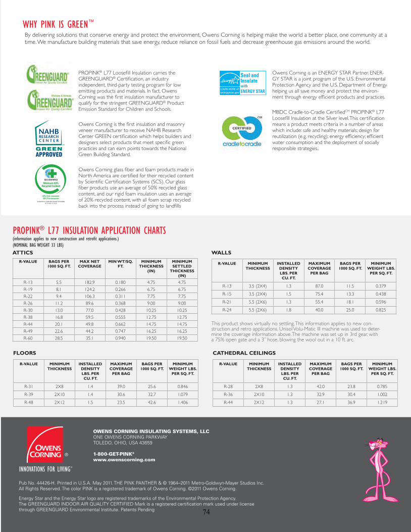
HIGH PERFORMANCE FIBERIZING TECHNOLOGYOwens Corning developed a new fiber which when blown creates a effectively distributed network of thermal reservoirs to resist heat transfer. This High Performance Fiberizing Technology produces a fiber construction that achieves a higher thermal performance in blown applications.
PROPRIETARY MANUFACTURING PROCESSTo produce PROPINK® L77 LooseFill Insulation, Owens Corning developed a proprietary manufacturing process specifically for loosefill products. This new process resulted in a yield improvement of 18% in terms of product performance.
VERSATILE MULTI-USE APPLICATION PROPINK® L77 LooseFill Insulation has been designed for use in walls, attics, cathedral ceilings and floors.
AIR INFILTRATION IN WALLSPROPINK® L77 LooseFill Insulation also offers exceptional performance for air-infiltration control and thermal protection.
Easily installed in walls and improved nesting for compaction
Can now be “dense packed” into walls at an installed density of up to 2.50 pounds per cubic foot*
Achieves an airflow reduction equal to cellulose, while providing R-Value greater than cellulose**
PROPINK® L77 LooseFill Insulation exhibits unsurpassed versatility—for installation, flexibility, performance, and productivity.
WHY PINK IS GREEN™
By delivering solutions that conserve energy and protect the environment, Owens Corning is helping make the world a better place, one community at a time. We manufacture building materials that save energy, reduce reliance on fossil fuels and decrease greenhouse gas emissions around the world.
OWENS CORNING INSULATING SYSTEMS, LLCONE OWENS CORNING PARKWAYTOLEDO, OHIO, USA 43659
1-800-GET-PINK®
www.owenscorning.comPROPINK L77 LOOSEFILL INSULATION
THE HIGHEST COVERAGE IN THE INDUSTRY THROUGH YIELD IMPROVEMENT
A new High Performance Fiberizing Technology boasts effectively distributed thermal reservoirs (see above) to achieve and maintain industry-standard
thermal requirements with less glass material (see below).
INTRODUCINGPROPINK® L77 LOOSEFILL INSULATIONLeave it to Owens Corning, the pioneer of fiberglass, to create a new fiber, loosefill product and manufacturing process that is so efficient and versatile, it is revolutionizing the industry. No other loosefill insulation measures up to its coverage, performance and energy-efficiency. PROPINK® L77 LooseFill Insulation leads the industry in thermal performance and yield.
OLDER FIBERS NEW HIGH PERFORMANCE FIBERIZING TECHNOLOGY
PROPINK® L77 LOOSEFILL INSULATION blows faster, is more energy-efficient, covers more square footage per bag, and can be used for multiple applications.
INSULATION THAT WORKS AS HARD AS YOU DO
PROPINK® L77 INSULATION APPLICATION CHARTS(information applies to new construction and retrofit applications.) (NOMINAL BAG WEIGHT 33 LBS)
This product shows virtually no settling. This information applies to new con-struction and retro applications. Unisol Volu-Matic III machine was used to deter-mine the coverage information above. The machine was set up in 3rd gear, with a 75% open gate and a 3” hose, blowing the wool out in a 10 ft. arc.
R-VALUE BAGS PER 1000 SQ. FT.
MAX NET COVERAGE
MIN WT/SQ. FT.
MINIMUM THICKNESS
(IN)
MINIMUM SETTLED
THICKNESS(IN)
R-13 5.5 182.9 0.180 4.75 4.75R-19 8.1 124.2 0.266 6.75 6.75R-22 9.4 106.3 0.311 7.75 7.75R-26 11.2 89.6 0.368 9.00 9.00R-30 13.0 77.0 0.428 10.25 10.25R-38 16.8 59.5 0.555 12.75 12.75R-44 20.1 49.8 0.662 14.75 14.75R-49 22.6 44.2 0.747 16.25 16.25R-60 28.5 35.1 0.940 19.50 19.50
ATTICS
R-VALUE MINIMUM THICKNESS
INSTALLED DENSITYLBS. PER CU. FT.
MAXIMUM COVERAGE
PER BAG
BAGS PER1000 SQ. FT.
MINIMUM WEIGHT LBS.
PER SQ. FT.
R-13 3.5 (2X4) 1.3 87.0 11.5 0.379
R-15 3.5 (2X4) 1.5 75.4 13.3 0.438
R-21 5.5 (2X6) 1.3 55.4 18.1 0.596
R-24 5.5 (2X6) 1.8 40.0 25.0 0.825
R-VALUE MINIMUM THICKNESS
INSTALLED DENSITYLBS. PER CU. FT.
MAXIMUM COVERAGE
PER BAG
BAGS PER1000 SQ. FT.
MINIMUM WEIGHT LBS.
PER SQ. FT.
R-28 2X8 1.3 42.0 23.8 0.785
R-36 2X10 1.3 32.9 30.4 1.002
R-44 2X12 1.3 27.1 36.9 1.219
R-VALUE MINIMUM THICKNESS
INSTALLED DENSITYLBS. PER CU. FT.
MAXIMUM COVERAGE
PER BAG
BAGS PER1000 SQ. FT.
MINIMUM WEIGHT LBS.
PER SQ. FT.
R-31 2X8 1.4 39.0 25.6 0.846
R-39 2X10 1.4 30.6 32.7 1.079
R-48 2X12 1.5 23.5 42.6 1.406
WALLS
CATHEDRAL CEILINGSFLOORS
INCHES OF INSULATION TO ACHIEVE R-30
AIR FLOWREDUCTION (%)
INSTALLED R-VALUE (2X4 WALL CAVITY)
PROPINKL77
2.5 pct
CELLULOSE
3.7 pct
49% 1649%
12.6PROPINK
L77
2.5 pct
CELLULOSE
3.7pct
PROPINK®
L77LOOSEFILL INSULATION
MULTI-USE APPLICATION PERFECT FOR WALLS, ATTICS,
CATHEDRAL CEILINGS AND FLOORS
I N T R O D U C I N G
18% YIELD IMPROVEMENT HIGHEST COVERAGE
IN THE INDUSTRY
10
11
9
12
PROPINKL77
JETSTREAM73.31
CLIMATE PRO
ATTIC GUARD
PROPINKRED BAG
INSULSAFE SP
10.25"
11.5"
10.38"
11.75"12.40"
10.88"
Source: Comparative Study on Air Infiltration by NAHB Research Center, 10/09
PROPINK® L77 Loosefill Insulation carries the GREENGUARD® Certification, an industry independent, third-party testing program for low emitting products and materials. In fact, Owens Corning was the first insulation manufacturer to qualify for the stringent GREENGUARD® Product Emission Standard for Children and Schools.
Owens Corning is the first insulation and masonry veneer manufacturer to receive NAHB Research Center GREEN certification which helps builders and designers select products that meet specific green practices and can earn points towards the National Green Building Standard.
Owens Corning glass fiber and foam products made in North America are certified for their recycled content by Scientific Certification Systems (SCS). Our glass fiber products use an average of 50% recycled glass content, and our rigid foam insulation uses an average of 20% recycled content, with all foam scrap recycled back into the process instead of going to landfills
Owens Corning is an ENERGY STAR Partner. ENER-GY STAR is a joint program of the U.S. Environmental Protection Agency and the U.S. Department of Energy helping us all save money and protect the environ-ment through energy efficient products and practices.
MBDC Cradle-to-Cradle CertifiedCM PROPINK® L77 Loosefill Insulation at the Silver level. This certification means a product meets criteria in a number of areas which include: safe and healthy materials; design for reutilization (e.g. recycling); energy efficiency; efficient water consumption and the deployment of socially responsible strategies..
Pub No. 44426-H. Printed in U.S.A. May 2011. THE PINK PANTHER & © 1964–2011 Metro-Goldwyn-Mayer Studios Inc. All Rights Reserved. The color PINK is a registered trademark of Owens Corning. ©2011 Owens Corning.
Energy Star and the Energy Star logo are registered trademarks of the Environmental Protection Agency. The GREENGUARD INDOOR AIR QUALITY CERTIFIED Mark is a registered certification mark used under license through GREENGUARD Environmental Institute. Patents Pending 74

Appendix A5.2b: Owens Corning ProPink L77 Documentation for Dense-Packing Sell Sheet, “A New Standard for Insulation & Air Infiltration”
75

A NEW STANDARD FOR INSULATION & AIR INFILTRATION.
The Ultimate In Air Infiltration and Thermal Performance.When it comes to choosing insulation for weatherization projects in existing homes, many factors – including thermal performance and air infi ltration – come into consideration. Many people assume cellulose is the best choice. But there is a better choice – Owens Corning™ PROPINK® L77 PINK Fiberglas™ Loosefi ll Insulation delivers exceptional performance for air-infi ltration control and thermal protection compared to cellulose insulation.
New Formulation. New Dense-Packing Capabilities. New Standard In Performance.Owens Corning™ PINK Fiberglas Loosefi ll Insulation has been reformulated to make it more effective for use in wall applications.
• Easily installed in walls and improved nesting for compaction
• Can now be “dense packed” into walls at an installed density of up to 2.50 pounds per cubic foot*
• Achieves an airfl ow reduction equal to cellulose, while providing R-value greater than cellulose**
Owens Corning™ PROPINK® L77 PINK FiberglasTM Loosefi ll Insulation
Cellulose
Source: Comparative Study on Air Infi ltration by NAHB Research Center, 10/09†
Easy Installation.• Easily fl ows around obstacles within a wall cavity, allowing for complete and uniform cavity fi ll, especially for “drill and fi ll” applications
• Dense packing of PINK Fiberglas Loosefi ll Insulation can be achieved by professional installers using most machines that are currently used to blow either fi berglass or cellulose insulation into existing wall cavities
Most tested. Most trusted.At Owens Corning, we apply over 70 years of building science expertise and rigorous testing to every product we make. Our PINK Fiberglas Loosefi ll Insulation products won’t settle or deteriorate with age, so there’s no danger of losing R-value over time. It’s noncombustible, meeting all model building codes for non combustibility. It won’t absorb moisture or support mold growth.‡ Simply put, it’s safe and one of the most effective insulation products you can use in a home.
* Ensure that the wall system can withstand the additional forces before dense packing any insulation material.
** R-value means resistance to heat fl ow. The higher the R-value, the greater the insulating power. Ask your seller for the fact sheet on R-values. To get the marked R-value, it is essential that insulation be installed properly.
† PROPINK® L77 PINK FiberglasTM Loosefi ll Insulation was tested using the Volumatic II. Results may vary based on equipment used.
‡ As manufactured, fi ber glass insulation is resistant to mold growth (tested per ASTM C 1338). However, mold growth can occur on building materials, including insulation, when it becomes contaminated with organic material and when water is present. To avoid mold growth on fi ber glass insulation, remove any water that has accumulated and correct or repair the source of that water as soon as possible. Insulation that has become wet should be inspected for evidence of residual moisture and contamination, and any insulation that is contaminated should be promptly removed and replaced.
Pub. No. 10011629. Printed in U.S.A. November 2009. The color PINK is a registered trademark of Owens Corning. ©2009 Owens Corning.
Owens Corning™ PROPINK® L77 PINK Fiberglas™ Loosefi ll Insulation
10011629.indd 110011629.indd 1 12/8/2009 2:06:15 PM12/8/2009 2:06:15 PM
76

Appendix A5.3: Owens Corning ProPink L77 Documentation for Weatherization / Retrofit Fact Sheet, “ProPink L77 Pink Fiberglas Unbonded Loosefill Insulation”
77
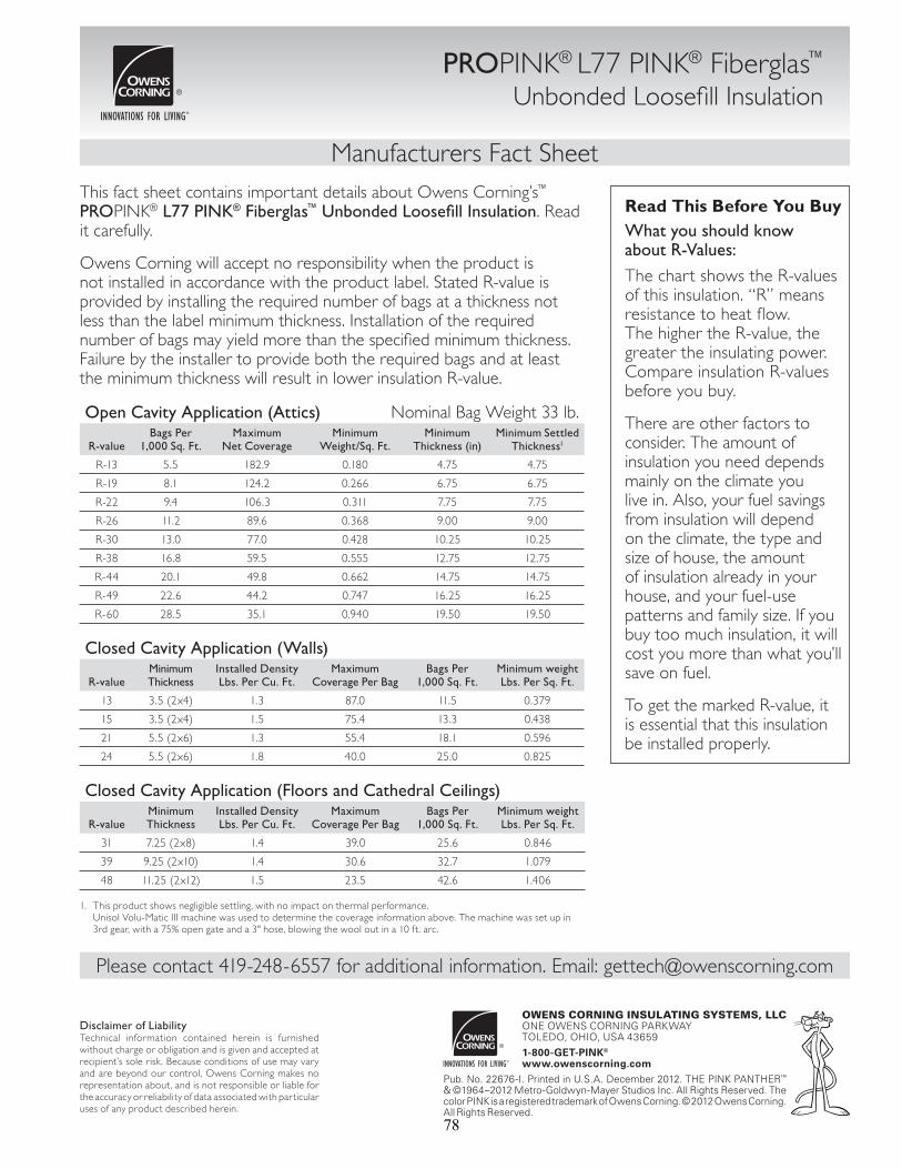
Manufacturers Fact Sheet
PROPINK® L77 PINK® Fiberglas™ Unbonded Loosefi ll Insulation
This fact sheet contains important details about Owens Corning’s™ PROPINK® L77 PINK® Fiberglas™ Unbonded Loosefi ll Insulation. Read it carefully.
Owens Corning will accept no responsibility when the product is not installed in accordance with the product label. Stated R-value is provided by installing the required number of bags at a thickness not less than the label minimum thickness. Installation of the required number of bags may yield more than the specifi ed minimum thickness. Failure by the installer to provide both the required bags and at least the minimum thickness will result in lower insulation R-value.
Read This Before You BuyWhat you should know about R-Values:The chart shows the R-values of this insulation. “R” means resistance to heat fl ow. The higher the R-value, the greater the insulating power. Compare insulation R-values before you buy.
There are other factors to consider. The amount of insulation you need depends mainly on the climate you live in. Also, your fuel savings from insulation will depend on the climate, the type and size of house, the amount of insulation already in your house, and your fuel-use patterns and family size. If you buy too much insulation, it will cost you more than what you’ll save on fuel.
To get the marked R-value, it is essential that this insulation be installed properly.
OWENS CORNING INSULATING SYSTEMS, LLCONE OWENS CORNING PARKWAYTOLEDO, OHIO, USA 436591-800-GET-PINK®
www.owenscorning.comPub. No. 22676-I. Printed in U.S.A. December 2012. THE PINK PANTHER™ & ©1964–2012 Metro-Goldwyn-Mayer Studios Inc. All Rights Reserved. The color PINK is a registered trademark of Owens Corning. © 2012 Owens Corning. All Rights Reserved.
Open Cavity Application (Attics) Nominal Bag Weight 33 lb.
R-valueBags Per
1,000 Sq. Ft.Maximum
Net CoverageMinimum
Weight/Sq. Ft. Minimum
Thickness (in)Minimum Settled
Thickness1
R-13 5.5 182.9 0.180 4.75 4.75
R-19 8.1 124.2 0.266 6.75 6.75
R-22 9.4 106.3 0.311 7.75 7.75
R-26 11.2 89.6 0.368 9.00 9.00
R-30 13.0 77.0 0.428 10.25 10.25
R-38 16.8 59.5 0.555 12.75 12.75
R-44 20.1 49.8 0.662 14.75 14.75
R-49 22.6 44.2 0.747 16.25 16.25
R-60 28.5 35.1 0.940 19.50 19.50
Closed Cavity Application (Walls)
R-valueMinimumThickness
Installed Density Lbs. Per Cu. Ft.
Maximum Coverage Per Bag
Bags Per 1,000 Sq. Ft.
Minimum weight Lbs. Per Sq. Ft.
13 3.5 (2x4) 1.3 87.0 11.5 0.379
15 3.5 (2x4) 1.5 75.4 13.3 0.438
21 5.5 (2x6) 1.3 55.4 18.1 0.596
24 5.5 (2x6) 1.8 40.0 25.0 0.825
Closed Cavity Application (Floors and Cathedral Ceilings)
R-valueMinimumThickness
Installed Density Lbs. Per Cu. Ft.
Maximum Coverage Per Bag
Bags Per 1,000 Sq. Ft.
Minimum weight Lbs. Per Sq. Ft.
31 7.25 (2x8) 1.4 39.0 25.6 0.846
39 9.25 (2x10) 1.4 30.6 32.7 1.079
48 11.25 (2x12) 1.5 23.5 42.6 1.406
1. This product shows negligible settling, with no impact on thermal performance.Unisol Volu-Matic III machine was used to determine the coverage information above. The machine was set up in 3rd gear, with a 75% open gate and a 3" hose, blowing the wool out in a 10 ft. arc.
Disclaimer of LiabilityTechnical information contained herein is furnished without charge or obligation and is given and accepted at recipient’s sole risk. Because conditions of use may vary and are beyond our control, Owens Corning makes no representation about, and is not responsible or liable for the accuracy or reliability of data associated with particular uses of any product described herein.
Please contact 419-248-6557 for additional information. Email: [email protected]
78
Appendix B: Loose-Fill Stone Wool Insulation Products (Not Intended for Dense-Pack Retrofit Applications)
• Amerrock RockWool Premium Plus • Rolan Fibra Mineral Nodular
• Roxul Rockfill • Thermafiber Spray Wool
79
Appendix B1: Amerrock RockWool Premium Plus
80

One Product with 5 Extraordinary Benefits...
*UHHQ5HF\FOHG6XVWDLQDEOH,QRUJDQLF5HVLVWV0ROG0LOGHZ)XQJXV)LUHSURRI/LVWHGE\8/DV121&RPEXVWLEOH7KHUPDO3HUIRUPDQFH59DOXHVRISHU,QFK6RXQG&RQWURO67&5DWLQJVDVKLJKDV
Submittal Approval: Job Name:
Contractor: Date:
RockWool Premium Plus™Triple Protection Insulation
81
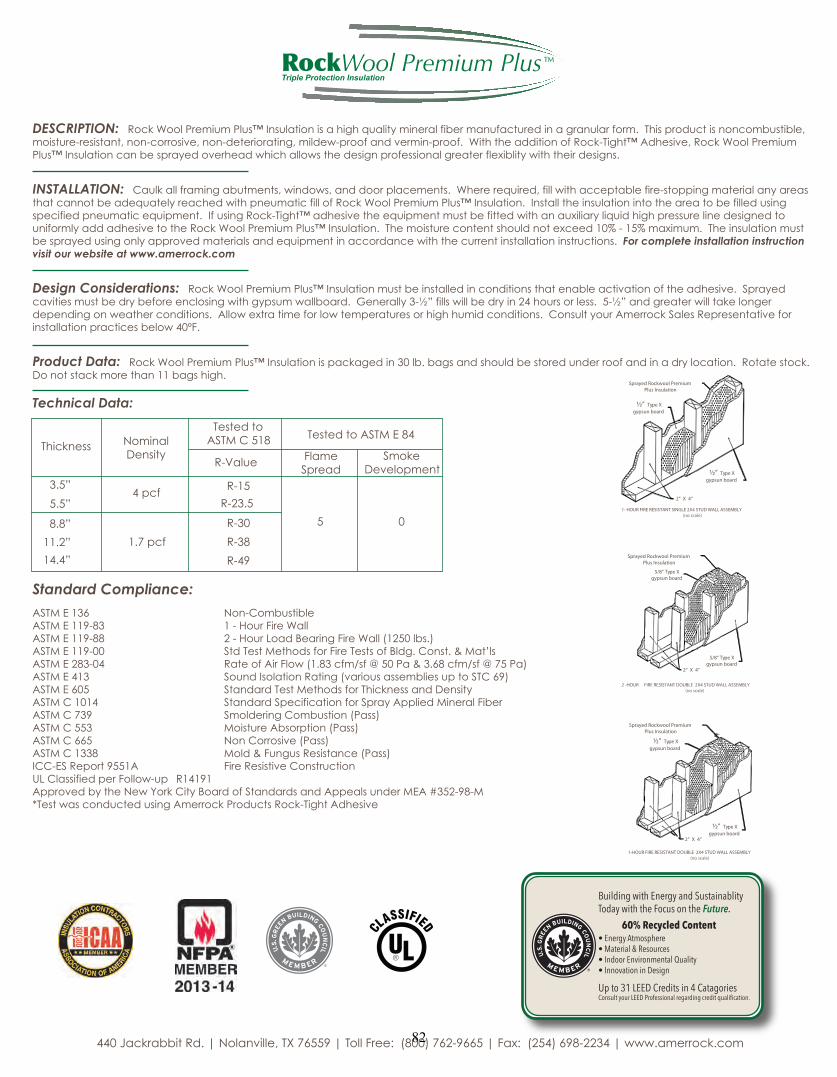
DESCRIPTION: 5RFN:RRO3UHPLXP3OXV,QVXODWLRQLVDKLJKTXDOLW\PLQHUDOILEHUPDQXIDFWXUHGLQDJUDQXODUIRUP7KLVSURGXFWLVQRQFRPEXVWLEOHPRLVWXUHUHVLVWDQWQRQFRUURVLYHQRQGHWHULRUDWLQJPLOGHZSURRIDQGYHUPLQSURRI:LWKWKHDGGLWLRQRI5RFN7LJKW$GKHVLYH5RFN:RRO3UHPLXP3OXV,QVXODWLRQFDQEHVSUD\HGRYHUKHDGZKLFKDOORZVWKHGHVLJQSURIHVVLRQDOJUHDWHUIOH[LEOLW\ZLWKWKHLUGHVLJQV
INSTALLATION: &DXONDOOIUDPLQJDEXWPHQWVZLQGRZVDQGGRRUSODFHPHQWV:KHUHUHTXLUHGILOOZLWKDFFHSWDEOHILUHVWRSSLQJPDWHULDODQ\DUHDVWKDWFDQQRWEHDGHTXDWHO\UHDFKHGZLWKSQHXPDWLFILOORI5RFN:RRO3UHPLXP3OXV,QVXODWLRQ,QVWDOOWKHLQVXODWLRQLQWRWKHDUHDWREHILOOHGXVLQJVSHFLILHGSQHXPDWLFHTXLSPHQW,IXVLQJ5RFN7LJKWDGKHVLYHWKHHTXLSPHQWPXVWEHILWWHGZLWKDQDX[LOLDU\OLTXLGKLJKSUHVVXUHOLQHGHVLJQHGWRXQLIRUPO\DGGDGKHVLYHWRWKH5RFN:RRO3UHPLXP3OXV,QVXODWLRQ7KHPRLVWXUHFRQWHQWVKRXOGQRWH[FHHGPD[LPXP7KHLQVXODWLRQPXVWEHVSUD\HGXVLQJRQO\DSSURYHGPDWHULDOVDQGHTXLSPHQWLQDFFRUGDQFHZLWKWKHFXUUHQWLQVWDOODWLRQLQVWUXFWLRQVFor complete installation instruction
visit our website at www.amerrock.com
Design Considerations: 5RFN:RRO3UHPLXP3OXV,QVXODWLRQPXVWEHLQVWDOOHGLQFRQGLWLRQVWKDWHQDEOHDFWLYDWLRQRIWKHDGKHVLYH6SUD\HGFDYLWLHVPXVWEHGU\EHIRUHHQFORVLQJZLWKJ\SVXPZDOOERDUG*HQHUDOO\îµILOOVZLOOEHGU\LQKRXUVRUOHVVîµDQGJUHDWHUZLOOWDNHORQJHUGHSHQGLQJRQZHDWKHUFRQGLWLRQV$OORZH[WUDWLPHIRUORZWHPSHUDWXUHVRUKLJKKXPLGFRQGLWLRQV&RQVXOW\RXU$PHUURFN6DOHV5HSUHVHQWDWLYHIRULQVWDOODWLRQSUDFWLFHVEHORZ)
Product Data: 5RFN:RRO3UHPLXP3OXV,QVXODWLRQLVSDFNDJHGLQOEEDJVDQGVKRXOGEHVWRUHGXQGHUURRIDQGLQDGU\ORFDWLRQ5RWDWHVWRFN'RQRWVWDFNPRUHWKDQEDJVKLJK
Technical Data:
Standard Compliance: $670( 1RQ&RPEXVWLEOH$670( +RXU)LUH:DOO$670( +RXU/RDG%HDULQJ)LUH:DOOOEV$670( 6WG7HVW0HWKRGVIRU)LUH7HVWVRI%OGJ&RQVW0DW·OV$670( 5DWHRI$LU)ORZFIPVI#3DFIPVI#3D$670( 6RXQG,VRODWLRQ5DWLQJYDULRXVDVVHPEOLHVXSWR67&$670( 6WDQGDUG7HVW0HWKRGVIRU7KLFNQHVVDQG'HQVLW\$670& 6WDQGDUG6SHFLILFDWLRQIRU6SUD\$SSOLHG0LQHUDO)LEHU$670& 6PROGHULQJ&RPEXVWLRQ3DVV$670& 0RLVWXUH$EVRUSWLRQ3DVV$670& 1RQ&RUURVLYH3DVV$670& 0ROG)XQJXV5HVLVWDQFH3DVV,&&(65HSRUW$ )LUH5HVLVWLYH&RQVWUXFWLRQ8/&ODVVLILHGSHU)ROORZXS 5$SSURYHGE\WKH1HZ<RUN&LW\%RDUGRI6WDQGDUGVDQG$SSHDOVXQGHU0($0 7HVWZDVFRQGXFWHGXVLQJ$PHUURFN3URGXFWV5RFN7LJKW$GKHVLYH
7HVWHGWR$670&1RPLQDO
'HQVLW\7KLFNQHVV
µ
µSFI
5
5
7HVWHGWR$670(
59DOXH )ODPH6SUHDG
6PRNH'HYHORSPHQW
Sprayed Rockwool Premium Plus Insulation
½” Type Xgypsun board
½” Type Xgypsun board
2” X 4”
1- HOUR FIRE RESISTANT SINGLE 2X4 STUD WALL ASSEMBLY(no scale)
Sprayed Rockwool PremiumPlus Insulation
5/8” Type Xgypsun board
5/8” Type Xgypsun board
2” X 4”
2 -HOUR FIRE RESISTANT DOUBLE 2X4 STUD WALL ASSEMBLY(no scale)
Sprayed Rockwool PremiumPlus Insulation
½” Type Xgypsun board
½” Type Xgypsun board
2” X 4”
1-HOUR FIRE RESISTANT DOUBLE 2X4 STUD WALL ASSEMBLY(no scale)
µ
µ
µ
SFI
5
5
5
-DFNUDEELW5G_1RODQYLOOH7;_7ROO)UHH_)D[_ZZZDPHUURFNFRP
RockWool Premium Plus™Triple Protection Insulation
Building with Energy and SustainablityToday with the Focus on the Future. 60% Recycled ContentŘ(QHUJ\$WPRVSKHUHŘ0DWHULDO5HVRXUFHVŘ,QGRRU(QYLURQPHQWDO4XDOLW\Ř,QQRYDWLRQLQ'HVLJQ
8SWR/(('&UHGLWVLQ&DWDJRULHV&RQVXOW\RXU/(('3URIHVVLRQDOUHJDUGLQJFUHGLWTXDOLƓFDWLRQ
82

Appendix B2: Rolan Fibra Mineral Nodular
83

Ventas, asesoría y servicio técnico: Descartes No. 104 Nueva Anzures 11590 D.F., 1036 0640 / Fax 5203 4739 www.rolan.com / [email protected] / [email protected]
La Fibra Mineral Nodular Rolan* es un termoaislante nodulizado compuesto por fibras minerales de roca de alta calidad, resistentes a la alta temperatura y contiene resina termofija como aglutinante que le da flexibilidad y baja densidad instalada.
A temperatura ambiente, la densidad debe ser entre 40 y 48 kg/m³ (2.5 a 3 lb/ft³). En aplicaciones hasta 250 °C, la densidad instalada debe ser de 64 kg/m³ (4 lb/ft³) y arriba de 250 °C no debe ser menor a 96 kg/m³ (6 lb/ft³).
Descripción
Se suministra en sacos de polietileno de 14 kg.Presentación
La Fibra Mineral Nodular Rolan* es apropiada para usarse en un amplio rango de temperaturas.Se instala en cavidades y espacios en los que no puede aplicarse una placa, rollo o cualquier producto preformado.
Los espacios en los que se instala la fibra deben poder soportar sin deformarse, la presión interna ejercida por la compresión necesaria para lograr la compactación de la fibra.Puede ser aplicada manualmente o con equipo neumático; se compacta solo en forma manual.
Aplicaciones
$OWDHILFLHQFLDWpUPLFD$KRUUDFRVWRVHQHUJpWLFRV\GHLQVWDODFLyQ$PSOLRUDQJRGHWHPSHUDWXUDV
9HUVDWLOLGDGGHDMXVWDUODGHQVLGDG)iFLOGHLQVWDODU
%HQHILFLRV
NOM-009 ENER Eficiencia energética en aislamientos térmicos industriales.ASTM C-764 Fibras granulas.ASTM C-519 Densidad de fibras minerales.
ASTM C-356 Encogimiento lineal.ASTM C-411 Comportamiento sobre la superficie caliente.
&XPSOLPLHQWRGHQRUPDV
Fibra Mineral Nodular Rolan*
7HPSHUDWXUDGHXVR$VEHVWR$EVRUFLyQGHKXPHGDG$OFDOLQLGDG&RPSRUWDPLHQWRDOIXHJR3URSDJDFLyQGHIODPD*HQHUDFLyQGHKXPR&RUURVLYLGDG5HVLVWHQWHDEDFWHULDV\KRQJRV
'HVGH&KDVWD&1RFRQWLHQHHQYROXPHQS+HQWUH\6HJ~Q$670(0
0
1XOD
'DWRVWpFQLFRV
0.000.020.040.060.080.100.120.14
0 50 100 150 200 250 300 350
ŽŶĚƵĐƟǀŝĚĂĚƚĠƌŵŝĐĂĞŶtŵ<;^/Ϳ
48 kg/m³ 64 kg/m³ 96 kg/m³
dĞŵƉĞƌĂƚƵƌĂŵĞĚŝĂΣ
Conversiones de SI a Sist. Inglés:tŵŬdžϲϵϯϱсdhŝŶŌϸŚΣ&;ΣdžϭϴͿнϯϮсΣ&
84

Appendix B3: Roxul Rockfill
85

Technical Product Information
General Product Information:
Description & Common Applications:
ROXUL® products are stone wool fiber insulations made from basalt rock and slag. This combination results in a non-combustible product with a melting point of approximately 2150°F (1177°C), which gives it excellent fire resistance properties. ROXUL stone wool is a water repellent yet vapour permeable material.
ROXUL ROCKFILL™ is a loose fill stone wool insulation for use in residential construction and attic renovations. ROCKFILL is designed to be easily aerated and spread out by hand, filling gaps in hard-to-reach places without requiring a blowing machine. The special characteristics of stone wool result in a light weight, water repellent, fire resistant and sound absorbing insulation that will not grow mold or mildew. ROCKFILL does not move or settle over time, maintaining expected R-value.
Compliance and Performance: CAN/ULC-S702 Mineral Fibre Thermal Insulation for Buildings Type 4, Complies CAN/ULC-S114 Test for Non-Combustibility Non-Combustible CAN/ULC S102 Surface Burning Characteristics Flame Spread = 0 CAN/ULC-S129
Smoulder Resistance
Smoke Developed = 0 Mass Loss <0.03%
NBC 1995, Article 9.25.2.2
Insulation Materials Conforms
Thermal Resistance: ASTM C 518 (C 177) R-value/inch @ 75°F 2.9 hr.ft².F/Btu*** RSI value/25.4 mm @ 24°C 0.52 m²K/W Installation: Installation in 3 easy steps
1) OPEN 2) AERATE 3) SPREAD
Cut open and remove from bag Fluff product to aerate Spread out evenly Cover exposed skin. When working un unventilated areas, wear a disposable mask. Clean the area using vacuum equipment. Dispose of waste according to local regulations. Rinse hands in cold water before washing. Ventilate working area if possible. Wear goggles when working overhead.
*MASTER FORMAT 1995 EDITION **MASTER FORMAT 2004 EDITION
86
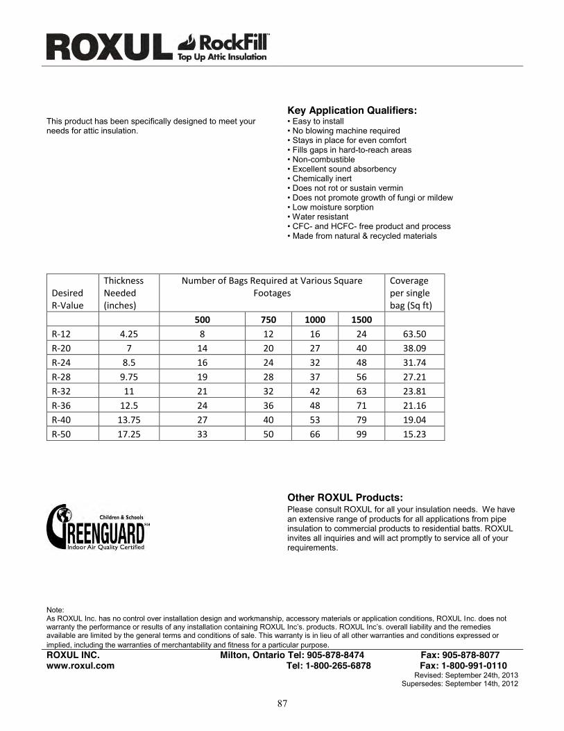
Key Application Qualifiers: This product has been specifically designed to meet your needs for attic insulation.
• Easy to install • No blowing machine required • Stays in place for even comfort • Fills gaps in hard-to-reach areas • Non-combustible • Excellent sound absorbency • Chemically inert • Does not rot or sustain vermin • Does not promote growth of fungi or mildew • Low moisture sorption • Water resistant • CFC- and HCFC- free product and process • Made from natural & recycled materials
Desired R-Value
Thickness Needed (inches)
Number of Bags Required at Various Square Footages
Coverage per single bag (Sq ft)
500 750 1000 1500
R-12 4.25 8 12 16 24 63.50
R-20 7 14 20 27 40 38.09
R-24 8.5 16 24 32 48 31.74
R-28 9.75 19 28 37 56 27.21
R-32 11 21 32 42 63 23.81
R-36 12.5 24 36 48 71 21.16
R-40 13.75 27 40 53 79 19.04
R-50 17.25 33 50 66 99 15.23
Other ROXUL Products:
Please consult ROXUL for all your insulation needs. We have an extensive range of products for all applications from pipe insulation to commercial products to residential batts. ROXUL invites all inquiries and will act promptly to service all of your requirements.
Note: As ROXUL Inc. has no control over installation design and workmanship, accessory materials or application conditions, ROXUL Inc. does not warranty the performance or results of any installation containing ROXUL Inc’s. products. ROXUL Inc’s. overall liability and the remedies available are limited by the general terms and conditions of sale. This warranty is in lieu of all other warranties and conditions expressed or implied, including the warranties of merchantability and fitness for a particular purpose. ROXUL INC. Milton, Ontario Tel: 905-878-8474 Fax: 905-878-8077 www.roxul.com Tel: 1-800-265-6878 Fax: 1-800-991-0110
Revised: September 24th, 2013 Supersedes: September 14th, 2012
87

Appendix B4: Thermafiber Spray Wool (Document covers many of Thermafiber’s Granulated Products)
88
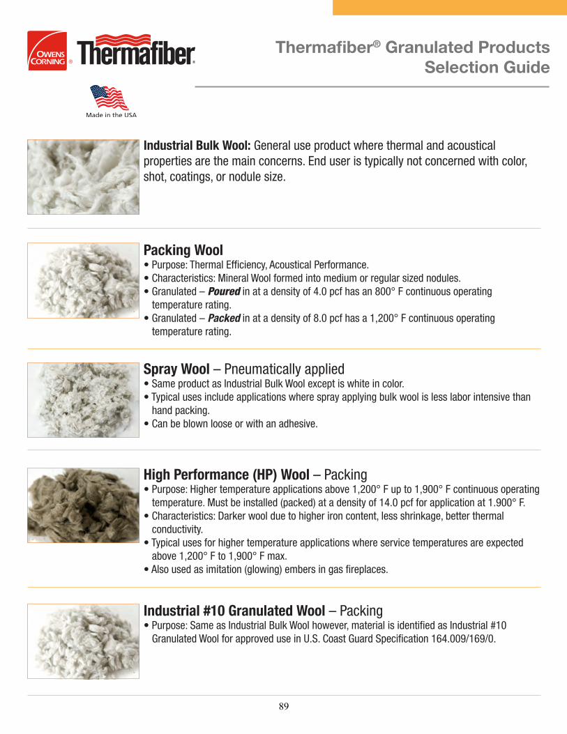
Thermafiber® Granulated Products Selection Guide
Industrial Bulk Wool: General use product where thermal and acoustical properties are the main concerns. End user is typically not concerned with color, shot, coatings, or nodule size.
Packing Wool
Pouredtemperature rating.
Packedtemperature rating.
Spray Wool
High Performance (HP) Wool
Industrial #10 Granulated Wool
89

Thermafiber® Filler/Reinforcement Wool (FRF)
3711 Mill Street | Wabash, IN 46992 | 888-TFIBER1 [834-2371] | [260] 563-2111 | www.thermafiber.com
TF 7
15 /
02-1
4 C
opyr
ight
201
4, T
herm
afibe
r, In
c. A
ll R
ight
s R
eser
ved
For Further Information:
Notice:
For more information on Thermafiber Industrial Bulk Wool or FRF products contact Thermafiber’s Technical Services Department at 1-888-834-2371 or visit our website www.thermafiber.com.
THERMAFIBER, Inc. shall not be liable for incidental and consequential damages, directly or indirectly sustained, nor for any loss caused by application of these goods not in accordance with current printed instructions or for other than the intended use. THERMAFIBER liability is expressly limited to replacement of defective goods. Any claim shall be deemed waived unless made in writing within thirty (30) days from date it was or reasonably should have been discovered. LEED® is a registered trademark of the US Green Building Council
FRF Wool:nodule size, color, chemistries, coatings, and shot contents are important to
Examples of Features:
Determining which FRF Product to use is based upon the following criteria:
Typical applications for Thermafiber FRF:
production or coatings.
Minimum
70%RecycledContent
90
Appendix C: Example of Dense-Packing Instructions From a Cellulose Insulation Manufacturer
91

Distributed by: US GreenFiber, LLC
2500 Distribution Street, Suite 200 Charlotte, NC 28203 (800) 228-0024 Fax (704) 379-0685
www.greenfi ber.com
Retrofi tting Existing Sidewalls with GreenFiber InsulationContractor Work Instructions
92

Before Installation Retrofi tting any part of a home’s envelope will cause changes in air, heat and moisture fl ow. Contractors must understand how this installation will impact the house, i.e., ventilation and combustion air requirements. Examine both the inside and outside of a home to determine areas that are inappropriate for installation. For example:• Do not insulate any home that has active knob and
tube wiring. • Where moisture related problems are evident, the source
of the problems must be determined and corrected before proceeding.
• Do not install insulation in stud runs where heat-producing devices such as an unprotected chimney, a fi replace, etc. might cause severe overheating.
• Building assembly details such as balloon framing, fi re blocking, pocket door connections, dry wall gaps or other leak points must be taken into consideration when blowing GreenFiber Insulation into a house.
• GreenFiber’s Material Data Safety Sheet (MSDS) requires the use of safety eyewear when installing this product. The insu-lation contractor is responsible for managing housekeeping and engineering controls below nuisance dust levels. Follow all OSHA guidelines for safety requirements including 29 CFR 1926.501 Duty to Have Fall Protection. Various other local, state and federal rules and guidelines may apply.
ApplicationThere are two basic techniques (Two-Hole or Double-Blow Method and One-Hole Tube Fill Method) used to fi ll existing, enclosed sidewall cavities. These techniques can be performed from either the exterior or interior of a home.
Installation through the interior wall is very diffi cult and is not detailed here. While it can be done, there is a wide range of other considerations related to someone currently occupying the home that present challenges to interior wall installation.
Required Equipment:• Insulation blowing machine capable of at least 2.9 psi at the end of the hose• Not all insulation blowing machines meet this require-
ment; please check with GreenFiber Customer Service – 800.228.0024 – for verifi cation.
• ¼-inch fi berglass rod• Hose clamps• Utility knife• Filter (such as sponge)• Wood, plastic, cork or Styrofoam plugs• Drill and a 2 to 3-inch hole saw / Forstner bit• 50-100 ft. of 3-6 inch inside diameter ribbed hose• 1 to 1½ -inch reducer nozzle• 12 ft., 1 1/8 to 1 ¼-inch inside diameter tube • Best practice: 1 1/8 to 1 ¼ - inch tube will match
sturdiness of a thin wall irrigation hose
• Note: When connecting hoses, a gradual reduction from the outlet to the 1 1/8 - 1 ¼ inch hose will yield the best results.
One-Hole Tube Fill MethodThe one-hole tube fi ll method is recommended by state Weatherization Assistance Programs for the retrofi t of sidewalls, and is the GreenFiber preferred method for retrofi tting existing sidewalls. When performing Weatherization Assistance Program work, follow the instructions below.
Density CheckGreenFiber requires the use of either a core sampling method or a bag count and volume method to assess the installed density of its products when using the Dry Dense-Pack method. GreenFiber specifi cations call for a minimum density of 3.5 pcf (pounds per cubic foot) in 2x4 and 2x6 cavities. These two methods are described below.
Retrofi tting Existing Sidewalls with GreenFiber Insulation – Contractor Work Instructions
The following instructions are for contractors for the
purpose of retrofi tting existing sidewalls with GreenFiber
Insulation. These instructions are designed for use with
GreenFiber’s INS770LD, INS765LD, INS745, INS735, or
INS515LD products for installation in sidewall cavities.
Follow the sidewall coverage charts on the bags to assure
that the proper amount of insulation is installed.
WI-6.19-10 Rev I 07/1393

Instructions for One-Hole Tube Fill Method1. Remove a section of exterior siding and drill a single 2
½-inch diameter hole through the sheathing approximately one foot from the bottom plate of the wall.
2. Using a hose clamp, attach the 1 to 1½ - inch reducer nozzle to the insulation blowing machine hose.
3. Using a hose clamp, attach the 12 ft., 1 1/8 or 1 ¼ - inch inside diameter tube to the end of the reducer nozzle.
4. Using the utility knife, cut the end of tube on a diagonal to facilitate snaking behind wiring and plumbing.
5. Suggested beginning settings for Insulation blowing machine:
a. Material gate set to 25% of total opening. b. Air setting at 60% of capacity.
NOTE: These settings are given as a starting point. Adjustment will be needed based on machine type and condition.
6. Insert cut end of the tube through the fi lter into the 2 ½-inch drilled hole and feed to within 6-inches of the top of the stud cavity. Note any fi re stops or other obstructions. Drill additional holes as needed if obstructions are present.
7. Turn on insulation blowing machine (Hold tube in place 6-inches from top). As material begins to fl ow, the cavity will fi ll bottom to top.
8. When you feel resistance from the tube, the cavity is full - DO NOT STOP BLOWING. You will now begin the Dry Dense-Pack Procedure. Dry Dense-Packing is required to achieve the minimum requirement of 3.5 pcf in wall cavities.
9. Dry Dense-Packing means you will begin compressing the material in the cavity and excess air will be forced out the entry hole. Move tube up and down 4 inches until material threatens to plug tube. Then retract the tube 8-10 inches.
10. Repeat Dry Dense-Packing procedures until within 6 inches of the entry hole.
11. When within 6 inches of entry hole quickly redirect tube downward to Dry Dense-Pack bottom of cavity.
12. Repeat Dry Dense-Packing procedures in bottom of cavity. 13. Retract tube to entry hole, jab forward 3 to 4 times to
fi nish Dry Dense-Packing entry area.14. Turn insulation blowing machine off. Keep tube in hole for
3 to 4 seconds before fully removing from cavity.
WI-6.19-10 Rev I 07/1394
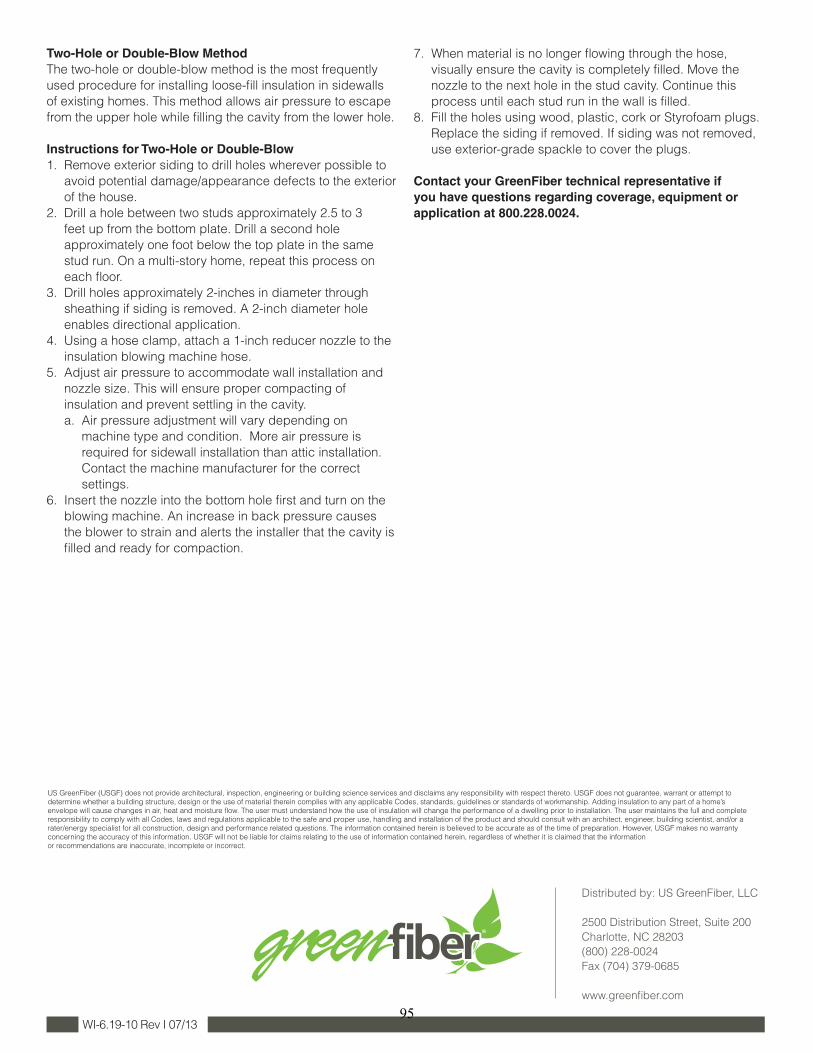
Two-Hole or Double-Blow MethodThe two-hole or double-blow method is the most frequently used procedure for installing loose-fi ll insulation in sidewalls of existing homes. This method allows air pressure to escape from the upper hole while fi lling the cavity from the lower hole.
Instructions for Two-Hole or Double-Blow1. Remove exterior siding to drill holes wherever possible to
avoid potential damage/appearance defects to the exterior of the house.
2. Drill a hole between two studs approximately 2.5 to 3 feet up from the bottom plate. Drill a second hole approximately one foot below the top plate in the same stud run. On a multi-story home, repeat this process on each fl oor.
3. Drill holes approximately 2-inches in diameter through sheathing if siding is removed. A 2-inch diameter hole enables directional application.
4. Using a hose clamp, attach a 1-inch reducer nozzle to the insulation blowing machine hose.
5. Adjust air pressure to accommodate wall installation and nozzle size. This will ensure proper compacting of insulation and prevent settling in the cavity.
a. Air pressure adjustment will vary depending on machine type and condition. More air pressure is required for sidewall installation than attic installation. Contact the machine manufacturer for the correct settings.
6. Insert the nozzle into the bottom hole fi rst and turn on the blowing machine. An increase in back pressure causes the blower to strain and alerts the installer that the cavity is fi lled and ready for compaction.
7. When material is no longer fl owing through the hose, visually ensure the cavity is completely fi lled. Move the nozzle to the next hole in the stud cavity. Continue this process until each stud run in the wall is fi lled.
8. Fill the holes using wood, plastic, cork or Styrofoam plugs. Replace the siding if removed. If siding was not removed, use exterior-grade spackle to cover the plugs.
Contact your GreenFiber technical representative if you have questions regarding coverage, equipment or application at 800.228.0024.
WI-6.19-10 Rev I 07/13
US GreenFiber (USGF) does not provide architectural, inspection, engineering or building science services and disclaims any responsibility with respect thereto. USGF does not guarantee, warrant or attempt to determine whether a building structure, design or the use of material therein complies with any applicable Codes, standards, guidelines or standards of workmanship. Adding insulation to any part of a home’s envelope will cause changes in air, heat and moisture fl ow. The user must understand how the use of insulation will change the performance of a dwelling prior to installation. The user maintains the full and complete responsibility to comply with all Codes, laws and regulations applicable to the safe and proper use, handling and installation of the product and should consult with an architect, engineer, building scientist, and/or a rater/energy specialist for all construction, design and performance related questions. The information contained herein is believed to be accurate as of the time of preparation. However, USGF makes no warranty concerning the accuracy of this information. USGF will not be liable for claims relating to the use of information contained herein, regardless of whether it is claimed that the information or recommendations are inaccurate, incomplete or incorrect.
Distributed by: US GreenFiber, LLC
2500 Distribution Street, Suite 200 Charlotte, NC 28203 (800) 228-0024 Fax (704) 379-0685
www.greenfi ber.com
95

DOE/GO- 102014-4531 November 2014
buildingamerica.gov

BA-1408: Airflow Resistance of Loose-Fill Mineral Fiber Insulations in Retrofit Applications
Limits of Liability and Disclaimer of Warranty:
Building Science documents are intended for professionals. The author and the publisher of this article have used their best efforts to provideaccurate and authoritative information in regard to the subject matter covered. The author and publisher make no warranty of any kind,expressed or implied, with regard to the information contained in this article.
The information presented in this article must be used with care by professionals who understand the implications of what they are doing. Ifprofessional advice or other expert assistance is required, the services of a competent professional shall be sought. The author and publishershall not be liable in the event of incidental or consequential damages in connection with, or arising from, the use of the information containedwithin this Building Science document.
About this Report
This report was prepared with the cooperation of the U.S. Department of Energy’sBuilding America Program.
Direct all correspondence to: Building Science Corproation, 3 Lan Drive, Suite 102, Westford,MA 01886.
About the Authors
Joseph Lstiburek, Ph.D., P.Eng., ASHRAE Fellow, is a principal of Building Science Corporation. Dr.Lstiburek has been a licensed Professional Engineer in the Province of Ontario since 1982 and is anASHRAE Fellow. He is also an Adjunct Professor of Building Science at the University of Toronto. Hehas over thirty years of experience in design, construction, investigation, and building science research.Through the Department of Energy's Building America program, Dr. Lstiburek has forged partnershipswith designers, builders, developers, materials suppliers and equipment manufacturers to build higherperformance buildings across the U.S.
Christopher Schumacher is a principal of Building Science Consulting Inc.
M. J. Fox is an associate at Building Science Consulting Inc.