Airflow Management System - Nordsonemanuals.nordson.com/finishing/files/Powder/108820A.pdfAirflow...
36
Airflow Management System Part 108 820A NORDSON CORPORATION D AMHERST, OHIO D USA
Transcript of Airflow Management System - Nordsonemanuals.nordson.com/finishing/files/Powder/108820A.pdfAirflow...
Airflow Management System
Part 108 820A
NORDSON CORPORATION � AMHERST, OHIO � USA

� 1996 Nordson CorporationAll rights reserved
108 820AIssued 7/96
Manual 35-14
Nordson Corporation welcomes requests for information, comments and inquiries about its products.
Address all correspondence to
Nordson Corporation555 Jackson StreetAmherst, OH 44001
Notice
This is a Nordson Corporation publication which is protected by copyright. No part of this document may bephotocopied, reproduced, or translated to another language without the prior written consent of Nordson
Corporation. The information contained in this publication is subject to change without notice.
Trademarks
100 Plus, Blue Box, ChromaFlex, CleanSleeve, CleanSpray, Control Coat, Cross-Cut, Easy Coat, Econo-Coat,Excel 2000, Flow Sentry, Isocoil, Isocore, Iso-Flo, Nordson, the Nordson logo, PRX, Pro-Flo, RBX, Ready-Coat,
Rhino, Select Coat, Select Cure, Shur-Lok, Smart Spray, System Sentry, Thread Coat, Tribomatic, and Versa-Sprayare registered trademarks of Nordson Corporation.
CPX, CanWorks, Excel 2000, PowderGrid, Pulse Spray, SCF, Versa-Coat, Versa Screen, Package of Values, andSwirl Coat are trademarks of Nordson Corporation.
Table of Contents i
� 1996 Nordson CorporationAll rights reserved
108 820AIssued 7/96
Manual 35-14
Table of Contents
1. Safety 1. . . . . . . . . . . . . . . . . . . . . . . . . . . . . . . . . . . . . . . . . . . . . . . . . . . . .
Safety Symbols 1. . . . . . . . . . . . . . . . . . . . . . . . . . . . . . . . . . . . . . . . . . .
Qualified Personnel 2. . . . . . . . . . . . . . . . . . . . . . . . . . . . . . . . . . . . . . .
Intended Use 3. . . . . . . . . . . . . . . . . . . . . . . . . . . . . . . . . . . . . . . . . . . . .
Installation 3. . . . . . . . . . . . . . . . . . . . . . . . . . . . . . . . . . . . . . . . . . . . . . .
Operation 5. . . . . . . . . . . . . . . . . . . . . . . . . . . . . . . . . . . . . . . . . . . . . . . .
Less-Obvious Dangers 7. . . . . . . . . . . . . . . . . . . . . . . . . . . . . . . . . . . .
Action in the Event of a System or Component Malfunction 7. . . . .
Maintenance and Repair 7. . . . . . . . . . . . . . . . . . . . . . . . . . . . . . . . . . .
Disposal 9. . . . . . . . . . . . . . . . . . . . . . . . . . . . . . . . . . . . . . . . . . . . . . . . .
2. Description 10. . . . . . . . . . . . . . . . . . . . . . . . . . . . . . . . . . . . . . . . . . . . . . . .
Manual AMS 10. . . . . . . . . . . . . . . . . . . . . . . . . . . . . . . . . . . . . . . . . . . .
Automatic AMS 11. . . . . . . . . . . . . . . . . . . . . . . . . . . . . . . . . . . . . . . . . .
Pulse-On-Demand 11. . . . . . . . . . . . . . . . . . . . . . . . . . . . . . . . . . . . . . .
3. Installation 12. . . . . . . . . . . . . . . . . . . . . . . . . . . . . . . . . . . . . . . . . . . . . . . .
Manual and Automatic AMS Control 12. . . . . . . . . . . . . . . . . . . . . . . .
Pulse-On-Demand Standalone System 12. . . . . . . . . . . . . . . . . . . . .
Excel 2000 System 12. . . . . . . . . . . . . . . . . . . . . . . . . . . . . . . . . . . .
Horizon 400 System 13. . . . . . . . . . . . . . . . . . . . . . . . . . . . . . . . . . .
4. Operation 14. . . . . . . . . . . . . . . . . . . . . . . . . . . . . . . . . . . . . . . . . . . . . . . . .
Versa Screen Systems 14. . . . . . . . . . . . . . . . . . . . . . . . . . . . . . . . . . .
Setting Up Automatic AMS Control 15. . . . . . . . . . . . . . . . . . . . . . .
Automatic Pulse-On-Demand 18. . . . . . . . . . . . . . . . . . . . . . . . . . .
Cleanup 20. . . . . . . . . . . . . . . . . . . . . . . . . . . . . . . . . . . . . . . . . . . . . .
Shutdown 20. . . . . . . . . . . . . . . . . . . . . . . . . . . . . . . . . . . . . . . . . . . .
Smart Coat Systems 20. . . . . . . . . . . . . . . . . . . . . . . . . . . . . . . . . . . . .
Setting Up Automatic AMS Control 20. . . . . . . . . . . . . . . . . . . . . . .
Automatic Pulse-On-Demand 22. . . . . . . . . . . . . . . . . . . . . . . . . . .
Cleanup 23. . . . . . . . . . . . . . . . . . . . . . . . . . . . . . . . . . . . . . . . . . . . . .
Shutdown 23. . . . . . . . . . . . . . . . . . . . . . . . . . . . . . . . . . . . . . . . . . . .
Table of Contentsii
� 1996 Nordson CorporationAll rights reserved
108 820AIssued 7/96
Manual 35-14
Manual AMS Control 23. . . . . . . . . . . . . . . . . . . . . . . . . . . . . . . . . . . . .
Cleanup 24. . . . . . . . . . . . . . . . . . . . . . . . . . . . . . . . . . . . . . . . . . . . . .
Shutdown 24. . . . . . . . . . . . . . . . . . . . . . . . . . . . . . . . . . . . . . . . . . . .
Evaluating the Powder Spray Pattern 25. . . . . . . . . . . . . . . . . . . . . . .
Standalone Pulse-On-Demand 25. . . . . . . . . . . . . . . . . . . . . . . . . . . .
5. Maintenance 26. . . . . . . . . . . . . . . . . . . . . . . . . . . . . . . . . . . . . . . . . . . . . . .
Daily 26. . . . . . . . . . . . . . . . . . . . . . . . . . . . . . . . . . . . . . . . . . . . . . . . . . .
Weekly 26. . . . . . . . . . . . . . . . . . . . . . . . . . . . . . . . . . . . . . . . . . . . . . . . .
6. Troubleshooting 27. . . . . . . . . . . . . . . . . . . . . . . . . . . . . . . . . . . . . . . . . . . .
Introduction 27. . . . . . . . . . . . . . . . . . . . . . . . . . . . . . . . . . . . . . . . . . . . .
Automatic Airflow Control 27. . . . . . . . . . . . . . . . . . . . . . . . . . . . . . .
Manual Airflow Control 27. . . . . . . . . . . . . . . . . . . . . . . . . . . . . . . . .
Standalone Pulse-On-Demand 27. . . . . . . . . . . . . . . . . . . . . . . . . .
Troubleshooting the Automatic AMS Control 28. . . . . . . . . . . . . . . . .
Troubleshooting the Manual AMS Control 30. . . . . . . . . . . . . . . . . . .
Troubleshooting the Standalone Pulse-On-Demand 31. . . . . . . . . .
Airflow Management System 1
� 1996 Nordson CorporationAll rights reserved
108 820AIssued 7/96
Manual 35-14
Airflow Management System
This section contains general safety instructions for using your Nordsonequipment. Task- and equipment-specific warnings are included in othersections of this manual where appropriate. Note all warnings and followall instructions carefully. Failure to do so may result in personal injury,death, or property damage.
To use this equipment safely,
� read and become familiar with the general safety instructionsprovided in this section of the manual before installing, operating,maintaining, or repairing this equipment.
� read and carefully follow the instructions given throughout this manualfor performing specific tasks and working with specific equipment.
� store this manual within easy reach of personnel installing, operating,maintaining, or repairing this equipment.
� follow all applicable safety procedures required by your company,industry standards, and government or other regulatory agencies.Refer to the National Fire Protection Association (NFPA) standard 33and to federal, state, regulatory agency, and local codes for rules andregulations covering installation and operation of powder spraysystems.
� obtain and read Material Safety Data Sheets (MSDS) for all materialsused.
Become familiar with the safety symbols presented in this section. Thesesymbols will alert you to safety hazards and conditions that may result inpersonal injury, death, or property and equipment damage.
WARNING: Failure to observe this warning may result inpersonal injury, death, or equipment damage.
1. Safety
Safety Symbols
Airflow Management System2
� 1996 Nordson CorporationAll rights reserved
108 820AIssued 7/96
Manual 35-14
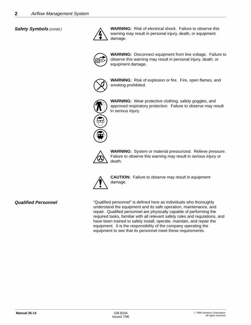
WARNING: Risk of electrical shock. Failure to observe thiswarning may result in personal injury, death, or equipmentdamage.
WARNING: Disconnect equipment from line voltage. Failure toobserve this warning may result in personal injury, death, orequipment damage.
WARNING: Risk of explosion or fire. Fire, open flames, andsmoking prohibited.
WARNING: Wear protective clothing, safety goggles, andapproved respiratory protection. Failure to observe may resultin serious injury.
WARNING: System or material pressurized. Relieve pressure.Failure to observe this warning may result in serious injury ordeath.
CAUTION: Failure to observe may result in equipmentdamage.
“Qualified personnel” is defined here as individuals who thoroughlyunderstand the equipment and its safe operation, maintenance, andrepair. Qualified personnel are physically capable of performing therequired tasks, familiar with all relevant safety rules and regulations, andhave been trained to safely install, operate, maintain, and repair theequipment. It is the responsibility of the company operating theequipment to see that its personnel meet these requirements.
Safety Symbols (contd.)
Qualified Personnel

Airflow Management System 3
� 1996 Nordson CorporationAll rights reserved
108 820AIssued 7/96
Manual 35-14
WARNING: Use of this equipment in ways other thandescribed in this manual may result in personal injury, death, orproperty and equipment damage. Use this equipment only asdescribed in this manual.
Nordson Corporation cannot be responsible for injuries or damagesresulting from nonstandard, unintended applications of its equipment.This equipment is designed and intended only for the purpose describedin this manual. Uses not described in this manual are consideredunintended uses and may result in serious personal injury, death, orproperty damage. Unintended uses may result from taking the followingactions:
� making changes to equipment that have not been recommended ordescribed in this manual or using parts that are not genuine Nordsonreplacement parts
� failing to make sure that auxiliary equipment complies with approvalagency requirements, local codes, and all applicable safety standards
� using materials or auxiliary equipment that are inappropriate orincompatible with your Nordson equipment
� allowing unqualified personnel to perform any task
Read the installation section of all system component manuals beforeinstalling your equipment. A thorough understanding of systemcomponents and their requirements will help you install the system safelyand efficiently.
� Allow only qualified personnel to install Nordson and auxiliaryequipment.
� Use only approved equipment. Using unapproved equipment in anapproved system may void agency approvals.
� Make sure all equipment is rated and approved for the environment inwhich you are using it.
� Follow all instructions for installing components and accessories.
� Install all electrical, pneumatic, gas, and hydraulic connections tolocal code.
Intended Use
Installation
Airflow Management System4
� 1996 Nordson CorporationAll rights reserved
108 820AIssued 7/96
Manual 35-14
� Install locking, manual, shutoff valves in the air supply lines to thesystem. This allows you to relieve air pressure and lock out thepneumatic system before undertaking maintenance and repairs.
� Install a locking disconnect switch or breaker in the service line aheadof any electrical equipment.
� Use only electrical wire of sufficient gauge and insulation to handlethe rated current demand. All wiring must meet local codes.
� Ground all electrically conductive equipment within 10 feet (3 meters)of the spray area. Ungrounded conductive equipment can store astatic charge which could ignite a fire or cause an explosion if a hotspark is discharged.
� Route electrical wiring, electrostatic cables, and air hoses and tubingalong a protected path. Make sure they will not be damaged bymoving equipment. Do not bend electrostatic cables around a radiusof less than 6 in. (152 mm).
� Install safety interlocks and approved, fast-acting fire detectionsystems. These shut down the spray system if the booth exhaust fanfails, a fire is detected, or other emergency situation develops.
� Make sure the spray area floor is conductive to ground and that theoperator’s platform is grounded.
� Use only designated lifting points or lugs to lift and move heavyequipment. Always balance and block loads when lifting to preventshifting. Lifting devices must be inspected, certified, and rated for agreater weight than the equipment being lifted.
� Protect components from damage, wear, and harsh environmentalconditions.
� Allow ample room for maintenance, material supply container drop-offand loading, panel accessibility, and cover removal.
� If safety devices must be removed for installation, install themimmediately after the work is completed and check them for properfunctioning.
Installation (contd.)

Airflow Management System 5
� 1996 Nordson CorporationAll rights reserved
108 820AIssued 7/96
Manual 35-14
Only qualified personnel, physically capable of operating the equipmentand with no impairments to their judgement or reaction times, shouldoperate this equipment.
Read all component manuals before operating a powder spray system.A thorough understanding of all components and their operation will helpyou operate the system safely and efficiently.
� Use this equipment only in the environments for which it is rated. Donot operate this equipment in humid, flammable, or explosiveenvironments unless it has been rated for safe operation in theseenvironments.
� Before starting this equipment, check all safety interlocks,fire-detection systems, and protective devices such as panels andcovers. Make sure all devices are fully functional. Do not operate thesystem if these devices are not working properly. Do not deactivateor bypass automatic safety interlocks or locked-out electricaldisconnects or pneumatic valves.
� Know where EMERGENCY STOP buttons, shutoff valves, and fireextinguishers are located. Make sure they work. If a componentmalfunctions, shut down and lock out the equipment immediately.
� Before operating, make sure all conductive equipment in the sprayarea is connected to a true earth ground.
� Never operate equipment with a known malfunction or leak.
� Do not attempt to operate electrical equipment if standing water ispresent.
� Never touch exposed electrical connections on equipment while thepower is ON.
� Do not operate the equipment at pressures higher than the ratedmaximum working pressure of any component in the system.
� Know the pinch points, temperatures, and pressures for all equipmentthat you are working with. Recognize potential hazards associatedwith these and exercise appropriate caution.
� Wear shoes with conductive soles, such as leather, or use groundingstraps to maintain a connection to ground when working with oraround electrostatic equipment.
Operation

Airflow Management System6
� 1996 Nordson CorporationAll rights reserved
108 820AIssued 7/96
Manual 35-14
� Do not wear or carry metallic objects (jewelry or tools) while workingwith or around electrostatic equipment. Ungrounded metal can storea static charge and cause harmful shocks.
� Maintain skin-to-metal contact between your hand and the gun handleto prevent shocks while operating manual electrostatic spray guns. Ifwearing gloves, cut away the palm or fingers.
� Keep parts of the body or loose clothing away from movingequipment or parts. Remove personal jewelry and cover or tie backlong hair.
� Wear National Institute of Occupational Safety and Health (NIOSH)approved respirators, safety glasses or goggles, and gloves, andwhile handling powder containers, filling hoppers, operating sprayequipment, and performing maintenance or cleaning tasks. Avoidgetting powder coatings on your skin.
� Never point manual guns at yourself or other persons.
� Do not smoke in the spray area. A lit cigarette could ignite a fire orcause an explosion.
� If you notice electrical arcing in a spray area, shut down the systemimmediately. An arc can cause a fire or explosion.
� Shut off electrostatic power supplies and ground gun electrodesbefore making adjustments to powder spray guns.
� Shut off moving equipment before taking measurements or inspectingworkpieces.
� Wash exposed skin frequently with soap and water, especially beforeeating or drinking. Do not use solvents to remove coating materialsfrom your skin.
� Do not use high-pressure compressed air to blow powder off yourskin or clothes. High-pressure compressed air can be injected underthe skin and cause serious injury or death. Treat all high-pressurefittings and hoses as if they could leak and cause injury.
Operation (contd.)
Airflow Management System 7
� 1996 Nordson CorporationAll rights reserved
108 820AIssued 7/96
Manual 35-14
Operators should also be aware of less-obvious dangers in the workplacethat often cannot be completely eliminated:
� exposed surfaces on the equipment which may be hot or have sharpedges and cannot be practically safeguarded
� electrical equipment which may remain energized for a period of timeafter the equipment has been shut off
� vapors and materials which may cause allergic reactions or otherhealth problems
� automatic hydraulic, pneumatic, or mechanical equipment or partsthat may move without warning
� unguarded, moving mechanical assemblies
Do not operate a system that contains malfunctioning components. If acomponent malfunctions, turn the system OFF immediately.
� Disconnect and lock out electrical power. Close and lock outhydraulic and pneumatic shutoff valves and relieve pressures.
� Allow only qualified personnel to make repairs. Repair or replace themalfunctioning component.
Allow only qualified personnel to perform maintenance, troubleshooting,and repair tasks.
� Always wear appropriate protective devices and use safety deviceswhen working on this equipment.
� Follow the recommended maintenance procedures in your equipmentmanuals.
� Do not service or adjust any equipment unless another person trainedin first aid and CPR is present.
� Use only genuine Nordson replacement parts. Using unapprovedparts or making unapproved modifications to equipment may voidagency approvals and create safety hazards.
Less-Obvious Dangers
Action in the Event of a Systemor Component Malfunction
Maintenance and Repair

Airflow Management System8
� 1996 Nordson CorporationAll rights reserved
108 820AIssued 7/96
Manual 35-14
� Disconnect, lock out, and tag electrical power at a disconnect orbreaker in the service line ahead of electrical equipment beforeservicing.
� Do not attempt to service electrical equipment if there is standingwater present. Do not service electrical equipment in a high-humidityenvironment.
� Use tools with insulated handles when working with electricalequipment.
� Do not attempt to service a moving piece of equipment. Shut off theequipment and lock out power. Secure equipment to preventuncontrolled movement.
� Relieve air pressures before servicing equipment. Follow the specificinstructions in this manual.
� Make sure that the room where you are working is sufficientlyventilated.
� If a “power on” test is required, perform the test carefully and thenshut off and lock out power as soon as the test is over.
� Connect all disconnected equipment ground cables and wires afterservicing the equipment. Ground all conductive equipment.
� Service lines connected to panel disconnect switches may still beenergized unless they are disconnected. Make sure the power is offbefore servicing. Wait 5 minutes for capacitors to discharge aftershutting off the electrical power.
� Turn off the electrostatic power supply and ground the gun electrodebefore adjusting or cleaning.
� Keep high-voltage connection points clean and insulated withdielectric grease or oil.
� Check all ground connections periodically with a standard ohmmeter.Resistance to ground must not exceed one megohm. If arcingoccurs, shut down the system immediately.
Maintenance and Repair (contd.)
Airflow Management System 9
� 1996 Nordson CorporationAll rights reserved
108 820AIssued 7/96
Manual 35-14
� Check interlock systems periodically to ensure their effectiveness.
WARNING: Operating faulty electrostatic equipment ishazardous and can cause electrocution, fire, or explosion.Make resistance checks part of your periodic maintenanceprogram.
� Do not store flammable materials in the spray area or room. Keepcontainers of flammable materials far enough away from spray boothsto prevent their inclusion in a booth fire. If a fire or explosion occurs,flammable materials in the area will increase the chances and theextent of personal injuries and property damage.
� Practice good housekeeping procedures. Do not allow dust orpowder coatings to accumulate in the spray area or booth or onelectrical equipment. Read this information carefully and followinstructions.
Dispose of equipment and materials used in operation and cleaningaccording to your local regulations.
Maintenance and Repair (contd.)
Disposal
3514002A
POTENTIOMETER
FREQUENCY
BOOTH MOTORS
DRIVE
Airflow Management System10
� 1996 Nordson CorporationAll rights reserved
108 820AIssued 7/96
Manual 35-14
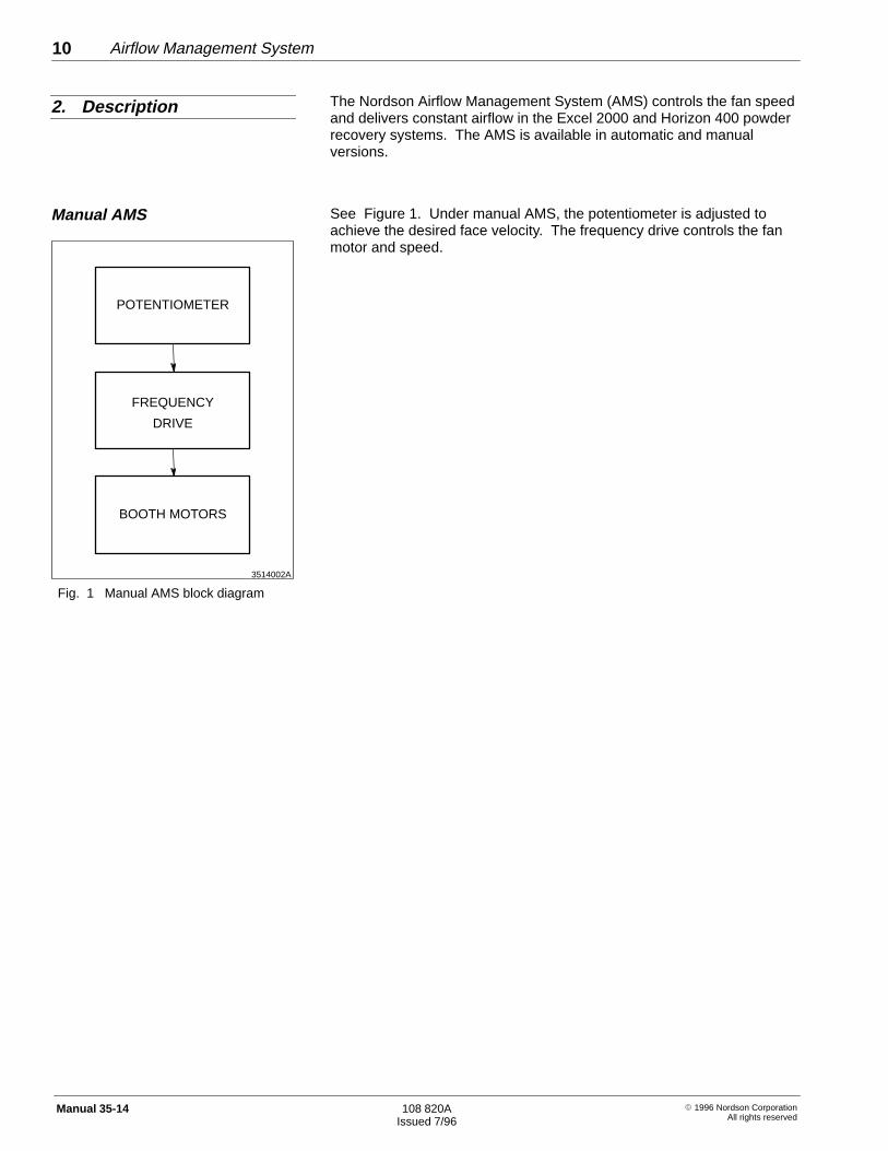
The Nordson Airflow Management System (AMS) controls the fan speedand delivers constant airflow in the Excel 2000 and Horizon 400 powderrecovery systems. The AMS is available in automatic and manualversions.
See Figure 1. Under manual AMS, the potentiometer is adjusted toachieve the desired face velocity. The frequency drive controls the fanmotor and speed.
Fig. 1 Manual AMS block diagram
2. Description
Manual AMS
3514003A
VERSA SCREEN
PROGRAMMABLE
FREQUENCY DRIVE
BOOTH MOTORS
CARTRIDGE FILTER
ORVERSA SCREEN 486
LOGICCONTROLLER
PRESSURETRANSDUCER
FINAL FILTERPRESSURE
TRANSDUCER
Airflow Management System 11
� 1996 Nordson CorporationAll rights reserved
108 820AIssued 7/96
Manual 35-14
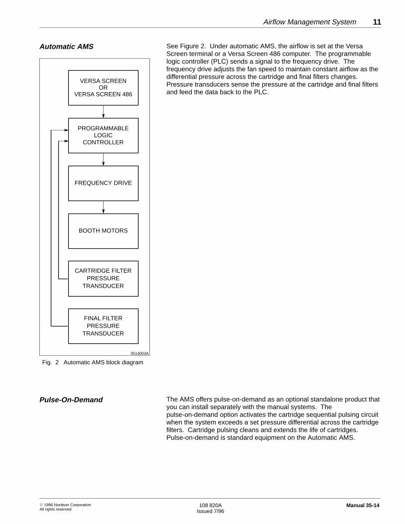
See Figure 2. Under automatic AMS, the airflow is set at the VersaScreen terminal or a Versa Screen 486 computer. The programmablelogic controller (PLC) sends a signal to the frequency drive. Thefrequency drive adjusts the fan speed to maintain constant airflow as thedifferential pressure across the cartridge and final filters changes.Pressure transducers sense the pressure at the cartridge and final filtersand feed the data back to the PLC.
Fig. 2 Automatic AMS block diagram
The AMS offers pulse-on-demand as an optional standalone product thatyou can install separately with the manual systems. Thepulse-on-demand option activates the cartridge sequential pulsing circuitwhen the system exceeds a set pressure differential across the cartridgefilters. Cartridge pulsing cleans and extends the life of cartridges.Pulse-on-demand is standard equipment on the Automatic AMS.
Automatic AMS
Pulse-On-Demand

Airflow Management System12
� 1996 Nordson CorporationAll rights reserved
108 820AIssued 7/96
Manual 35-14
WARNING: Allow only qualified personnel to perform thefollowing tasks. Observe and follow the safety instructions inthis document and all other related documentation.
The parts supplied with the AMS depend on your system and itsconfiguration. Each installation includes three application-specificdrawings:
� system electrical connection diagram� pneumatic schematic� system electrical schematic diagrams
Contact your Nordson controls engineer for hardware and softwareinstallation procedures.
Use these procedures to install the pulse-on-demand option on anExcel 2000 or Horizon 400 system.
Excel 2000 System
1. Refer to the pneumatic schematic. Install the cartridge filterdifferential pressure switch
� inside the blowdown timer box,
� with the cartridge filter differential pressure switch diaphragm in avertical position.
2. Install a bulkhead fitting in the blowdown timer box.
3. Install a sintered-bronze vent in the blowdown timer box.
4. Install a pneumatic fitting on the cartridge filter differential pressureswitch low pressure port.
5. Connect an air line between these parts:
� cartridge filter differential pressure switch low pressure port fitting� bulkhead fitting inside the blowdown timer box
6. Install a tee fitting into the air line between the Magnehelic gage onthe fan module support and the fan module pneumatic fitting.
3. Installation
Manual and Automatic AMSControl
Pulse-On-Demand StandaloneSystem

Airflow Management System 13
� 1996 Nordson CorporationAll rights reserved
108 820AIssued 7/96
Manual 35-14
Excel 2000 System (contd.)
7. Connect an air line between these parts:
� remaining tee fitting port, see step 6� the bulkhead fitting outside of the blowdown box
8. Refer to the system electrical connection diagram. Remove the metaljumper from the pressure switch terminals on the blowdown timerboard.
9. Connect two wires from the pressure switch terminal of the blowdowntimer to these terminals on the cartridge filter differential pressureswitch:
� common� norm open
NOTE: Adjust the cartridge pressure differential switch when youoperate the system for the first time. Refer to Operation, StandalonePulse-On-Demand in this manual.
Horizon 400 System
1. Refer to the pneumatic schematic. Install the cartridge filterdifferential pressure switch
� inside the motor starter panel
� with the cartridge filter differential pressure switch diaphragm in avertical position
2. Install a tee fitting in the air line that connects the collector filter gaugeto the collector filter bulkhead fitting.
3. Install a pneumatic fitting on the cartridge filter differential pressureswitch low pressure port.
4. Refer to the system electrical connection diagram. Remove the metaljumper from the pressure switch terminals on the blowdown timerboard.
5. Connect two wires from the pressure switch terminals of theblowdown timer to these terminals on the cartridge filter differentialpressure switch:
� common� norm open
NOTE: Adjust the cartridge pressure differential switch when youoperate the system for the first time. Refer to Operation, StandalonePulse-On-Demand in this manual.
Airflow Management System14
� 1996 Nordson CorporationAll rights reserved
108 820AIssued 7/96
Manual 35-14
WARNING: Allow only qualified personnel to perform thefollowing tasks. Observe and follow the safety instructions inthis document and all other related documentation.
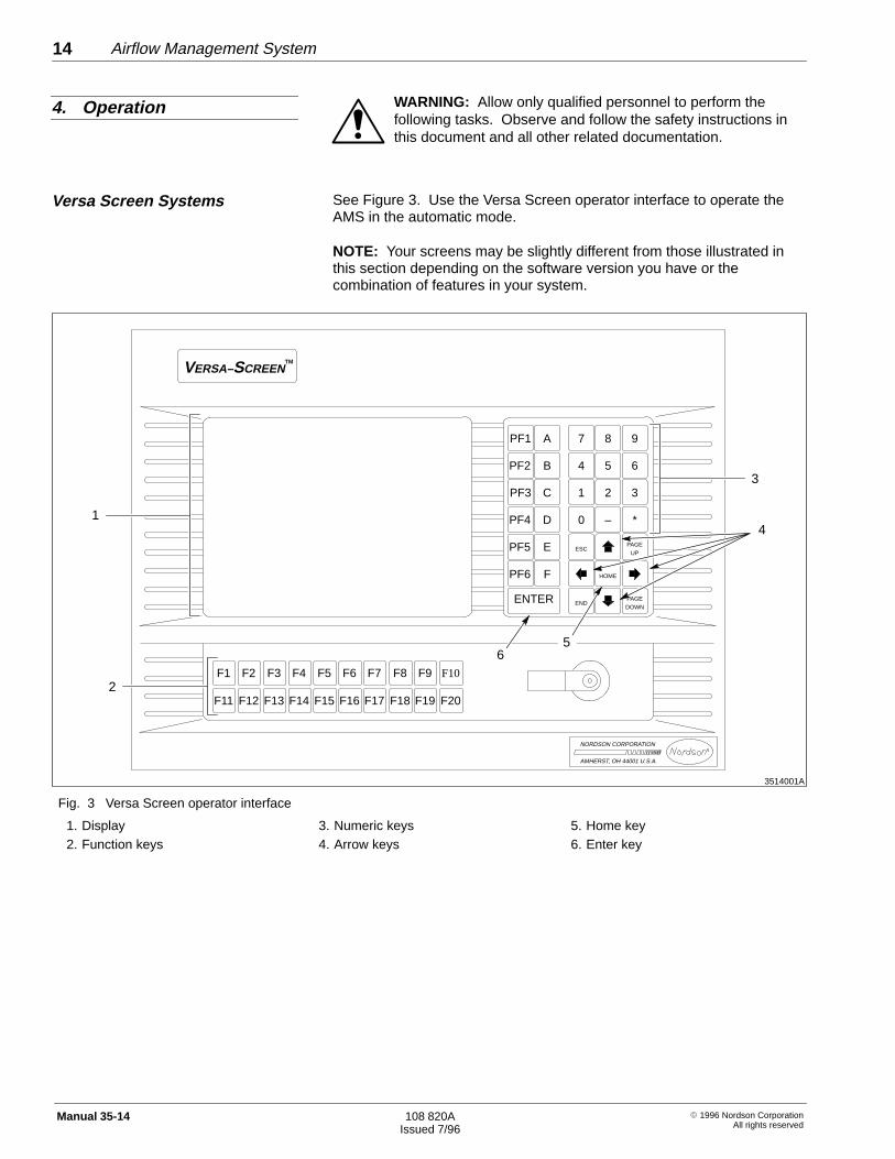
See Figure 3. Use the Versa Screen operator interface to operate theAMS in the automatic mode.
NOTE: Your screens may be slightly different from those illustrated inthis section depending on the software version you have or thecombination of features in your system.
3514001A
3
PF1 A 7 8 9
4 5 6
1 2 3
0 – *
ESCPAGE
HOME
ENDPAGE
PF2 B
PF3 C
PF4 D
PF5 E
PF6 F
ENTER
F1
F11
F2
F12
F3
F13
F4
F14
F5
F15
F6
F16
F7
F17
F8
F18
F9
F19
F10
F20
VERSA–SCREEN
UP
DOWN
TM
NORDSON CORPORATION
AMHERST, OH 44001 U.S.A.
2
1
56
4
Fig. 3 Versa Screen operator interface
1. Display2. Function keys
3. Numeric keys4. Arrow keys
5. Home key6. Enter key
4. Operation
Versa Screen Systems
Airflow Management System 15
� 1996 Nordson CorporationAll rights reserved
108 820AIssued 7/96
Manual 35-14
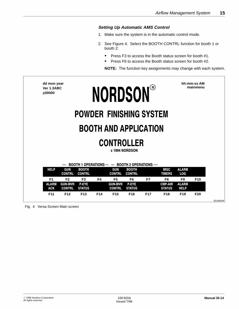
Setting Up Automatic AMS Control
1. Make sure the system is in the automatic control mode.
2. See Figure 4. Select the BOOTH CONTRL function for booth 1 orbooth 2:
� Press F3 to access the Booth status screen for booth #1.� Press F6 to access the Booth status screen for booth #2.
NOTE: The function key assignments may change with each system.
3514004A
F1 F2 F3 F4 F5 F6 F7 F8 F9 F10
��� �� ����� �� ����� ���� �����
������ ������ ������ ������ ����� ��
F11 F12 F13 F14 F15 F16 F17 F18 F19 F20
����� ������ ��� ������ ��� ������� �����
�� ������ ������ ������ ������ ������ ���
dd mon yearVer 1.3ABC+00000
hh:mm:ss AMmainmenuR
��������������
����������������� �����������������
Fig. 4 Versa Screen Main screen

Airflow Management System16
� 1996 Nordson CorporationAll rights reserved
108 820AIssued 7/96
Manual 35-14
Setting Up Automatic AMS Control (contd.)
3. See Figure 5. Press F3 to select MANUAL MOTORS and access theMotor Control screen.
4. See Figure 6. Press the home key until the cursor is at the AIRFLOW CONTROL SETPOINT prompt (1).
NOTE: The airflow setpoint can range from 1 to 10.
5. Using the numeric keys, enter 5 as a starting point. Press ENTER.
6. Change the AIR FLO MODE to automatic. Press F8 until the AIRFLOW SELECTED MODE (2) toggles to AUTOMATIC AIR FLOW.
7. Press F3 to select EXHSTR START and turn on the motor and fan.
NOTE: Allow the system to stabilize for 30 seconds after you turn onthe fan.
3514005A
F1 F2 F3 F4 F5 F6 F7 F8 F9 F10
���� ���� ������ ���(��� ��� ����� ���� ���(� �� ����� ����
����� ������ ������ ������ ������ ���� ���� ��� � ����
F11 F12 F13 F14 F15 F16 F17 F18 F19 F20
����� ���� ������ ���(��� ���(��� ���� � ����� ����
� � ���� ������ ������� ������ ���� ��� ����
dd mon year
+00000
$$%%&&���
��#�����
�������������
'����������������������� ���
�������
�������
�������
�������
�� ��� ���������
������� ���������� ������
������������������
�!�������
�� �������������������
�� ��� ���
�� ����������
����������
�������������
���(�� ����������
����
��������
���(�� ����
�����������������������
������� ����������������� ���������
��� �� ������
���������
��������������
���������������
����"���������
���������
�������� ��������
�����
�� ����������
�� ���������
�����������
�������
������������
Fig. 5 Versa Screen Booth Status screen

Airflow Management System 17
� 1996 Nordson CorporationAll rights reserved
108 820AIssued 7/96
Manual 35-14
Setting Up Automatic AMS Control (contd.)
8. Measure the booth vestibule face velocity with a Nordson velometer,or an equivalent instrument. Make sure the face velocity is30.5–36.6 m/min (100–120 ft/min). If the velocity is too
� high — reduce the airflow setpoint one number at a time� low — increase the airflow setpoint one number at a time
9. Evaluate the powder spray pattern and powder containment. Refer toEvaluating the Powder Spray Pattern in this manual.
10. Press F20 to select MAIN MENU and return to the main screen.
3514006A
F1 F2 F3 F4 F5 F6 F7 F8 F9 F10
���� �� �#���� ���!� ���� ���� ������ � �� ���!
�� �� �� �� �� �� �� �� �� �� ���� ��� ������
F11 F12 F13 F14 F15 F16 F17 F18 F19 F20
� �� �� �#���� ���!� ���� ���� ����� �� ��� � ��
�� ���� ���� ���� ���� ���� ,!��� ! � �� ���
dd mon year
+00000
&&�''�**� �
�%�����
� ����
� ����
� ����
� ����
������������ ������� �� � �
� �������������!�
�#� ����
���!�
������ �����
������ �����
������"��������������
��� ���� ������"
������"�� ����������
��� ���� ������"
��� ����()�� � �
������"��������
����������+(�� ��������� ����"��
�������������
��� ��������
�$������� ��
���!������"��
�#���,!����� ��
���!�������������
�������������
��� ����������� �
�������� �������
��"�������� ���"�
1
2
Fig. 6 Versa Screen Motor Status screen
1. AIR FLOW CONTROL SETPOINTprompt
2. AIR FLOW SELECTED MODEindicator

Airflow Management System18
� 1996 Nordson CorporationAll rights reserved
108 820AIssued 7/96
Manual 35-14
Automatic Pulse-On-Demand
To operate the pulse-on-demand feature, set the upper and lowerpressure limits to define when cartridges begin to pulse. Make sure thePULSING MODE is ON DEMAND.
1. From the Booth Status screen, press F13 to select FILTER STATUS.
2. See Figure 7. Press F19 to select CHANGE VALUES and highlightthe START POINT cursor.
a. Using the numeric keys, enter 6 as a starting point.
b. Press ENTER.
3. Press F19 to select CHANGE VALUES and highlight the STOPSETPOINT cursor.
a. Using the numeric keys, enter 4 as a starting point.
b. Press ENTER.
NOTE: The values (in. wc) are recommended by Nordson for theupper and lower pressure limits. During production, evaluate coatingcharacteristics and change these limits as necessary to obtain thedesired results.
4. Select the PULSE MODE. Press F7 until ON DEMAND appears forthe PULSING MODE.
5. Press F20 to select MAIN MENU and return to the main screen.

Airflow Management System 19
� 1996 Nordson CorporationAll rights reserved
108 820AIssued 7/96
Manual 35-14
Automatic Pulse-On-Demand (contd.)
3514007A
F1 F2 F3 F4 F5 F6 F7 F8 F9 F10
���� � ��� ����� ���!
���� ��� ������
F11 F12 F13 F14 F15 F16 F17 F18 F19 F20
����� ������ ����
��� !�� �� ���
dd mon year
+00000
(( ++ ..���
��#�����
������
�),$*
�����
������
���������
���� ��
��������
�����
"������
��������
�����
"������
��������
����� � ����������
������ � �
�������� �����
�����
��������
�����
����
��������
�����
�
���
�
���
�
���
�
���
�
��
�
�
�
�
�
�
�
"
�
������
�$-/-)%'&
��
�
�
�
�
�
�
�
�
�
�
�
�
�
�
"
�
������
Fig. 7 Versa Screen Filter Status screen

Airflow Management System20
� 1996 Nordson CorporationAll rights reserved
108 820AIssued 7/96
Manual 35-14
Cleanup
Set the Airflow mode to CLEANUP:
1. See Figure 4. Select BOOTH CONTRL:
� Press F3 to access the Booth Status screen for booth #1.� Press F6 to access the Booth Status screen for booth #2.
2. See Figure 5. Press F3 to select MANUAL MOTORS and access theMotor Control screen.
3. See Figure 6. Change the AIR FLO MODE. Press F8 until the AIRFLOW SELECTED MODE (2) toggles to CLEAN UP.
NOTE: The fan speed increases to its maximum speed. The high facevelocity and airflow into the color module maximize powder containment.
4. After cleanup, return the fan speed to AUTOMATIC AIR FLOW:
a. Change the AIR FLO MODE. Press F8 until the AIR FLOWSELECTED MODE (2) toggles to AUTOMATIC AIR FLOW.
b. Press F20 to select MAIN MENU and return to the main screen.
Shutdown
1. See Figure 4. From the Main screen, press the BOOTH CONTRLkey on the display to access the Booth Status screen.
2. See Figure 5. Press F13 to select EXHSTR STOP and turn off themotor and fan.
3. Press F20 to select MAIN MENU and return to the main screen.
The Smart Coat system uses a Versa Screen 486 personal computer andpointing device (mouse) for operator input.
NOTE: Your screens may be slightly different from those illustrated inthis section depending on the software version you have or thecombination of features in your system.
Setting Up Automatic AMS Control
Access the Motor Control Center screen:
1. From the Versa Screen 486 computer screen, select either theBOOTH 1 or BOOTH 2 icon on the upper menu bar.
2. Select Motors. See Figure 8. The Motor Control Center screenappears.
Smart Coat Systems

Airflow Management System 21
� 1996 Nordson CorporationAll rights reserved
108 820AIssued 7/96
Manual 35-14
Setting Up Automatic AMS Control (contd.)
3. As a starting point, enter a preset value of 5. Use the mouse to movethe slide or press # and enter a numeric value.
4. Change the operating mode to automatic. Toggle MODE underSelect Mode until Automatic appears.
5. Select START to start the motor and fan. All motors will start.
NOTE: Allow the system to stabilize for 30 seconds after you turn onthe fan.
6. Measure the booth vestibule face velocity with a Nordson velometer,or an equivalent instrument. Make sure the face velocity is30.5–36.6 m/min (100–120 ft/min). If the velocity is too
� high — reduce the airflow preset one number at a time� low — increase the airflow preset one number at a time
7. Evaluate the powder spray pattern and powder containment. Refer toEvaluating the Powder Spray Pattern in this manual.
8. Return to the Main screen. Select Menu from the upper menu bar.
3514008A
OFF
MODE
MODE
Oscillator 1 AMSTM Control
START
STOP
SYSTEMCONTROLSTARTING
OFF
Oscillator 2
OFF
Sleve
OFF
Air Lock
OFF
Exhauster 1
% Exhauster #1
100
92
84
76
68
60
OFF
Exhauster 2
% Exhauster #2
100
92
84
76
68
60
Preset
#
Enable Manual Motor Controls
10
8
6
5
3
1
Select Mode
Automatic
Blowdown Mode
Continuous
1
2
3
Fig. 8 Smart Coat Motor Control Center screen
1. Select Mode2. Blowdown Mode
3. Preset

Airflow Management System22
� 1996 Nordson CorporationAll rights reserved
108 820AIssued 7/96
Manual 35-14
Automatic Pulse-On-Demand
1. Access the Powder Booth Operation screen:
a. From the Versa Screen 486 computer Main screen, select BoothStatus from the upper menu bar.
b. Select Adjust Setpoints from the Filter Status section.
c. See Figure 9. The Filter Setpoint Adjustments inset screenappears.
2. Use the left and right arrow icons to set the Cartridge Blowdown StartSP and the Cartridge Blowdown Stop SP. The values recommendedby Nordson are:
� Cartridge Blowdown Start SP 6.0 in.-wc� Cartridge Blowdown Stop SP 4.0 in.-wc
3. Select Done.
NOTE: During production, evaluate coating characteristics andchange these limits as necessary to obtain the desired results.
4. Set the Blowdown Mode to On-Demand. Access the Motor ControlCenter screen:
a. From the Versa Screen 486 computer Main screen, select Motorsfrom the upper menu bar to
b. See Figure 8. Toggle Mode in the Blowdown Mode section untilOn-Demand appears.
3514009A
Filter Setpoin t Adjustments
Adjust Setpoints
Final Filter Warning Limit
Final Filter Warning Limit
Cartridge Filter Warning Limit
Cartridge Blowdown Start SP
Cartridge Blowdown Stop SP
#.#
#.#
#.#
#.#
#.#
Done
Fig. 9 Smart Coat Filter Setpoint Adjustments screen

Airflow Management System 23
� 1996 Nordson CorporationAll rights reserved
108 820AIssued 7/96
Manual 35-14
Cleanup
1. See Figure 8. From the Motor Control Center screen, toggle Modeunder the Select Mode section until Clean Up appears.
NOTE: The fan speed increases to its maximum speed. The highface velocity and airflow into the color module maximize powdercontainment.
2. After cleanup, return the fan speed to AUTOMATIC AIR FLOW:
3. Toggle Mode until Automatic appears.
Shutdown
1. Access the Motor Control Center screen.
2. Select STOP.
3. Select Menu from the upper menu bar to return to the Main screen.
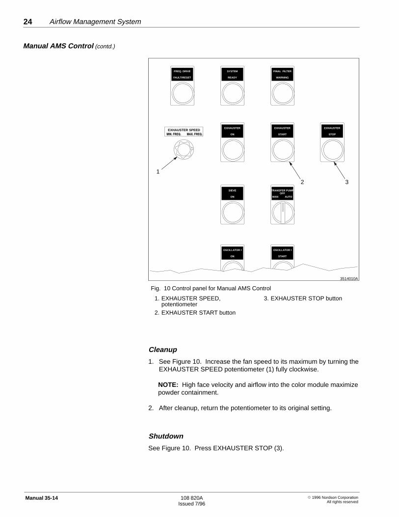
See Figure 10.
1. Set the EXHAUSTER SPEED potentiometer (1) to the minimumspeed (fully counterclockwise).
2. Press EXHAUSTER START (2) to start the fan motor. Allow thesystem to stabilize for 30 seconds after you turn on the fan.
3. Measure the booth vestibule face velocity with a Nordson velometer,or an equivalent instrument. If the velocity is not 30.5–36.6 m/min(100–120 ft/min), perform the following:
a. Use the EXHAUSTER SPEED potentiometer (1) to increase ordecrease velocity.
b. Allow the system to stabilizes for 30 seconds, then measure theface velocity again.
4. Evaluate the powder spray pattern and powder containment. Refer toEvaluating the Powder Spray Pattern in this manual.
Manual AMS Control
Airflow Management System24
� 1996 Nordson CorporationAll rights reserved
108 820AIssued 7/96
Manual 35-14
3514010A
EXHAUSTER
START
EXHAUSTER
ON
EXHAUSTER
STOP
FINAL FILTER
WARNING
SYSTEM
READY
TRANSFER PUMP
MAN
SIEVE
ON
OSCILLATOR I
START
OSCILLATOR I
ON
FREQ. DRIVE
FAULT/RESET
AUTOOFF
EXHAUSTER SPEED��������� ��������
1
32
Fig. 10 Control panel for Manual AMS Control
1. EXHAUSTER SPEED,potentiometer
2. EXHAUSTER START button
3. EXHAUSTER STOP button
Cleanup
1. See Figure 10. Increase the fan speed to its maximum by turning theEXHAUSTER SPEED potentiometer (1) fully clockwise.
NOTE: High face velocity and airflow into the color module maximizepowder containment.
2. After cleanup, return the potentiometer to its original setting.
Shutdown
See Figure 10. Press EXHAUSTER STOP (3).
Manual AMS Control (contd.)

3514011A
1 2
Airflow Management System 25
� 1996 Nordson CorporationAll rights reserved
108 820AIssued 7/96
Manual 35-14
1. Hang the parts you that want to spray on the conveyor. Run the partsthrough the booth while the guns are spraying.
2. If the powder spray pattern pulls away from the guns, the airflow maybe set too high. Before reducing the airflow, check the powdercontainment at each opening. If the
� powder containment is adequate, reduce the airflow value onenumber at a time to achieve the proper powder spray
� powder escapes the booth at any opening, increase the airflowvalue one number at a time to achieve the proper powdercontainment
3. Measure the booth vestibule face velocity with a velometer. Note theface velocity for future reference.
NOTE: As powder collects in the cartridges, the airflow decreases.As the cartridges pulse, the airflow increases. Measure the facevelocity periodically during production and adjust the fan speed asnecessary.
See Figure 11. For a standalone pulse-on-demand system, adjust thepressure limit on the cartridge filter differential pressure switch when thecartridges reach the desired upper pressure limit for the first time.
NOTE: You cannot make this adjustment until the cartridge fills withenough powder to reach the desired upper pressure limit.
1. Remove the cover (2) to expose the pressure limit adjustmentscrew (1).
2. Allow the cartridge filter pressure to rise to the desired upper pressurelimit. If pulsing starts prior to achieving the limit, turn the pressurelimit adjustment screw (1) clockwise until the pulsing stops. Repeatuntil desired pressure limit is achieved.
3. When the system reaches the desired upper pressure limit, turn thepressure limit adjustment screw (1) counter clockwise until thecartridges begin to pulse.
4. Replace the cover (2).
NOTE: The pulsing will stop approximately 0.5 in.-wc below theupper pressure set point.
Fig. 11 Filter differential pressureswitch
1. Pressure limit adjustment screw2. Cover
Evaluating the Powder SprayPattern
Standalone Pulse-On-Demand

Airflow Management System26
� 1996 Nordson CorporationAll rights reserved
108 820AIssued 7/96
Manual 35-14
The following paragraphs provide maintenance instructions for the AMS.
Check the face velocity with a velometer at all booth openings. Thevelocity must be sufficient to contain powder and provide the desiredspray pattern.
CAUTION: Failed or damaged cartridges will affect AMSperformance. Contact Nordson Customer Service, PowderBusiness Group before you attempt to zero or recalibrate thetransducers.
Check the pressure readings from the cartridge and final filter pressuretransducers.
� When the fan is off, the pressure readings should be at zero. If theyare not, the transducers may need zeroing, recalibrating, or replacing.
� If the pressure readings are near zero when the fan is running, thetransducers may need zeroing, recalibrating, or replacing.
Inspect the cartridge and final filters according to the instructions given ineither the Excel or Horizon system manuals.
5. Maintenance
Daily
Weekly
Airflow Management System 27
� 1996 Nordson CorporationAll rights reserved
108 820AIssued 7/96
Manual 35-14
WARNING: Allow only qualified personnel to perform thefollowing tasks. Observe and follow the safety instructions inthis document and all other related documentation.
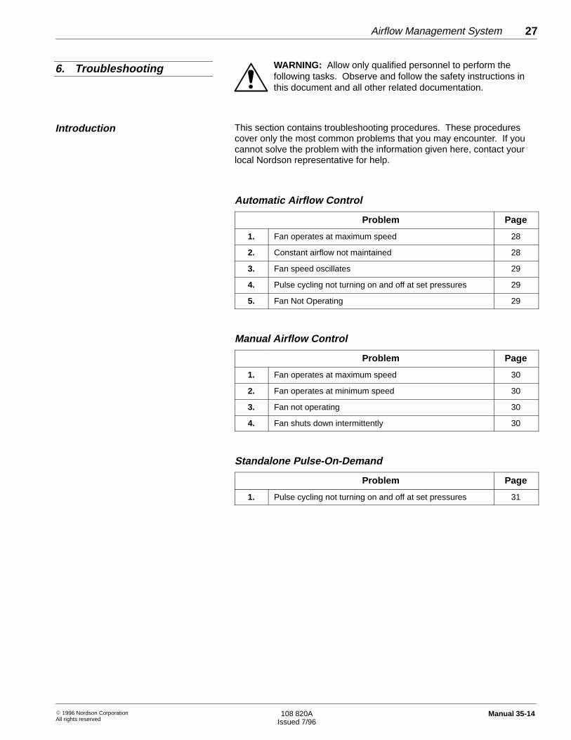
This section contains troubleshooting procedures. These procedurescover only the most common problems that you may encounter. If youcannot solve the problem with the information given here, contact yourlocal Nordson representative for help.
Automatic Airflow Control
Problem Page
1. Fan operates at maximum speed 28
2. Constant airflow not maintained 28
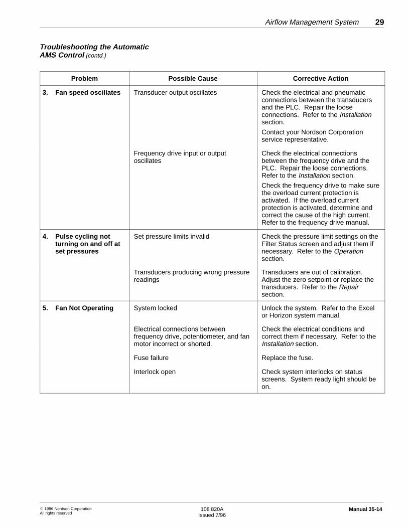
3. Fan speed oscillates 29
4. Pulse cycling not turning on and off at set pressures 29
5. Fan Not Operating 29
Manual Airflow Control
Problem Page
1. Fan operates at maximum speed 30
2. Fan operates at minimum speed 30
3. Fan not operating 30
4. Fan shuts down intermittently 30
Standalone Pulse-On-Demand
Problem Page
1. Pulse cycling not turning on and off at set pressures 31
6. Troubleshooting
Introduction
Airflow Management System28
� 1996 Nordson CorporationAll rights reserved
108 820AIssued 7/96
Manual 35-14
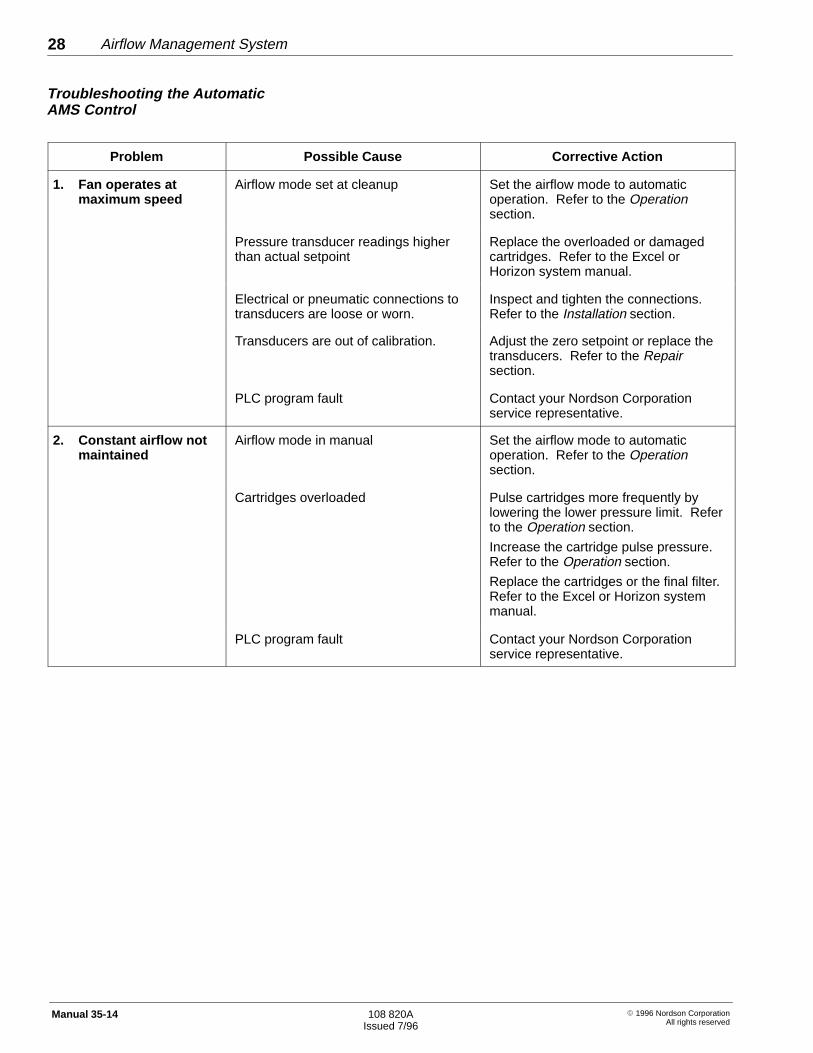
Problem Possible Cause Corrective Action
1. Fan operates atmaximum speed
Airflow mode set at cleanup Set the airflow mode to automaticoperation. Refer to the Operationsection.
Pressure transducer readings higherthan actual setpoint
Replace the overloaded or damagedcartridges. Refer to the Excel orHorizon system manual.
Electrical or pneumatic connections totransducers are loose or worn.
Inspect and tighten the connections.Refer to the Installation section.
Transducers are out of calibration. Adjust the zero setpoint or replace thetransducers. Refer to the Repairsection.
PLC program fault Contact your Nordson Corporationservice representative.
2. Constant airflow notmaintained
Airflow mode in manual Set the airflow mode to automaticoperation. Refer to the Operationsection.
Cartridges overloaded Pulse cartridges more frequently bylowering the lower pressure limit. Referto the Operation section.
Increase the cartridge pulse pressure.Refer to the Operation section.
Replace the cartridges or the final filter.Refer to the Excel or Horizon systemmanual.
PLC program fault Contact your Nordson Corporationservice representative.
Troubleshooting the AutomaticAMS Control
Airflow Management System 29
� 1996 Nordson CorporationAll rights reserved
108 820AIssued 7/96
Manual 35-14
Problem Possible Cause Corrective Action
3. Fan speed oscillates Transducer output oscillates Check the electrical and pneumaticconnections between the transducersand the PLC. Repair the looseconnections. Refer to the Installationsection.
Contact your Nordson Corporationservice representative.
Frequency drive input or outputoscillates
Check the electrical connectionsbetween the frequency drive and thePLC. Repair the loose connections.Refer to the Installation section.
Check the frequency drive to make surethe overload current protection isactivated. If the overload currentprotection is activated, determine andcorrect the cause of the high current.Refer to the frequency drive manual.
4. Pulse cycling notturning on and off atset pressures
Set pressure limits invalid Check the pressure limit settings on theFilter Status screen and adjust them ifnecessary. Refer to the Operationsection.
Transducers producing wrong pressurereadings
Transducers are out of calibration.Adjust the zero setpoint or replace thetransducers. Refer to the Repairsection.
5. Fan Not Operating System locked Unlock the system. Refer to the Excelor Horizon system manual.
Electrical connections betweenfrequency drive, potentiometer, and fanmotor incorrect or shorted.
Check the electrical conditions andcorrect them if necessary. Refer to theInstallation section.
Fuse failure Replace the fuse.
Interlock open Check system interlocks on statusscreens. System ready light should beon.
Troubleshooting the AutomaticAMS Control (contd.)
Airflow Management System30
� 1996 Nordson CorporationAll rights reserved
108 820AIssued 7/96
Manual 35-14
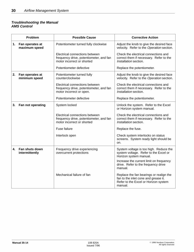
Problem Possible Cause Corrective Action
1. Fan operates atmaximum speed
Potentiometer turned fully clockwise Adjust the knob to give the desired facevelocity. Refer to the Operation section.
Electrical connections betweenfrequency drive, potentiometer, and fanmotor incorrect or shorted
Check the electrical connections andcorrect them if necessary. Refer to theInstallation section.
Potentiometer defective Replace the potentiometer.
2. Fan operates atminimum speed
Potentiometer turned fullycounterclockwise
Adjust the knob to give the desired facevelocity. Refer to the Operation section.
Electrical connections betweenfrequency drive, potentiometer, and fanmotor incorrect or open.
Check the electrical connections andcorrect them if necessary. Refer to theInstallation section.
Potentiometer defective Replace the potentiometer.
3. Fan not operating System locked Unlock the system. Refer to the Excelor Horizon system manual.
Electrical connections betweenfrequency drive, potentiometer, and fanmotor incorrect or shorted
Check the electrical connections andcorrect them if necessary. Refer to theInstallation section.
Fuse failure Replace the fuse.
Interlock open Check system interlocks on statusscreens. System ready light should beon.
4. Fan shuts downintermittently
Frequency drive experiencingovercurrent protections
System voltage is too high. Reduce thesystem voltage. Refer to the Excel orHorizon system manual.
Increase the current limit on frequencydrive. Refer to the frequency drivemanual.
Mechanical failure of fan Replace the fan bearings or realign thefan to the inlet cone and grease it.Refer to the Excel or Horizon systemmanual.
Troubleshooting the ManualAMS Control

Airflow Management System 31
� 1996 Nordson CorporationAll rights reserved
108 820AIssued 7/96
Manual 35-14
Problem Possible Cause Corrective Action
1. Pulse cycling notturning on and off atset pressures.
Pressure limits invalid Check the cartridge filter differentialpressure switch setting and adjust ifnecessary. Refer to the Operationsection.
Poor pneumatic connection betweentransducers, cartridges, and final filter
Check the pneumatic connections andcorrect if necessary. Refer to theInstallation section.
Troubleshooting theStandalone Pulse-On-Demand

Airflow Management System32
� 1996 Nordson CorporationAll rights reserved
108 820AIssued 7/96
Manual 35-14