Aircraft Equation of motion - Madras Institute of Technology
32
Aircraft Equation of motion A.Kaviyarasu Assistant Professor Department of Aerospace Engineering Madras Institute Of Technology Chromepet, Chennai Prepared by Kaviyarasu A, MIT Chennai
Transcript of Aircraft Equation of motion - Madras Institute of Technology

Aircraft Equation of motion
A.Kaviyarasu
Assistant Professor
Department of Aerospace Engineering
Madras Institute Of Technology
Chromepet, Chennai
Prepared
by
Kaviyarasu A, MIT Chennai

• In developing the response side of the aircraft force equations, several additional assumptions will be made.
• First an aircraft is assumed to be a rigid body– This assumes that the different parts of the aircraft are not moving with
respect to each other
• The mass of the aircraft is also assumed to be constant, which is reasonable over a relatively short duration of time.
Kaviyarasu A, MIT Chennai

• This assumption allows Newton’s 2nd law to be rewritten as
• Newton’s 2nd law is only valid with respect to an inertialreference frame, the equations can be expressed in the vehiclebody axis system.
• If the equations are expressed in the body axis system, the factthat the system is rotating with respect to an inertial referenceframe.
inertial
inertial
d Vm ma F
dt
Kaviyarasu A, MIT Chennai

• Expressing the body measurement in the inertial reference frame
Inertial body body bodybodya V V
ˆˆ ˆbodyV Ui Vj Wk
, , bodyThe velocity vector in the body axis system is definedV as
, , , , ,
whereU V and W are the velocities in the x y and z body axes
respectively
Kaviyarasu A, MIT Chennai

• The aircraft angular rate in the body axis system, Body, isdefined as
ˆˆ ˆbody Pi Qj Rk
ˆˆ ˆ
Inertial body
body body
U i j k
a V P Q R
W U V W
, , , , ,
.
P Q and R are the roll pitch and yaw rates respectively
expressed in the body axis
body
Kaviyarasu A, MIT Chennai

• Multiplying the inertial acceleration in the body axis system by the mass m of the aircraft yields the three force equations
Inertial body
body
U QW RV
a V RU PW
W PV QU
x
y body
zbodybody
U QW RV F
m V RU PW F F
W PV QU F
Kaviyarasu A, MIT Chennai

response side of the force equa
x
y
z
tion
m U QW RV F
m V RU PW F
m W PV QU F
Kaviyarasu A, MIT Chennai

Applied forces
Kaviyarasu A, MIT Chennai

• The previous section developed the left-hand side, or response side, of the force equations. The right-hand side of each equation consists of the applied forces that act on the aircraft. They consist of the gravity forces, the aerodynamic forces, and the thrust forces.
x x x
y y y
z z z
G A T
G A T
G A T
m U QW RV F F F
m V RU PW F F F
m W PV QU F F F
Kaviyarasu A, MIT Chennai

• The left-hand sides of the equations (response equation) weredeveloped in the body axis system, the right-hand side ( the aboveequation) must also be in the body axis system.
• Therefore, each of the forces must be represented in the body axissystem for the previous equations to be valid.
Kaviyarasu A, MIT Chennai

• The gravity forces, aerodynamic forces, and thrust forces werepreviously determined in the body axis system. Therefore, the threeforce equations in the body axis system are
sin cos sin cos
sin cos
cos cos sin cos sin
y y
T
A T
T
Three force equation
m U QW RV mg D A L A T
m V RU PW mg F F
m W PV QU mg D A L A T
Kaviyarasu A, MIT Chennai

Moment Equation
Kaviyarasu A, MIT Chennai

• The three moment equations are determined by applying Newton’s 2ndlaw in a manner similar to the three force equations. Newton’s 2nd lawstates that the time rate of change in the angular momentum of theaircraft is equal to the applied moments acting on the aircraft, namely,
• H is the angular momentum of the aircraft and is defined as
Inertial
dHM
dt
H r mV
Kaviyarasu A, MIT Chennai

Response Side of Moment Equations
• A six-step procedure will be used to methodically build up theresponse side of the three moment equations. This provides both amathematical and physical insight into the equations.
Kaviyarasu A, MIT Chennai
Differential mass in body axis system

• Step 1. The first step is to examine a small elemental mass, dm, of theaircraft that is located at some distance from the aircraft’s center of gravity.It will be assumed that the elemental mass is rotating about the aircraftcenter of gravity with a positive roll rate, pitch rate, and yaw rate (P, Q, andR, respectively). The distance from the center of gravity to the small mass isdefined as
where x, y, and z are the distances in the x, y, and z axes of the body axis system
ˆˆ ˆdmr xi yj zk
Kaviyarasu A, MIT Chennai

• Step 2. Next an expression is developed for the velocity of the small mass,dm, solely because of its rotation about the center of gravity. The velocityfor the movement of the center of gravity of the aircraft was taken intoaccount in the development of the three force equations.The velocity of the mass relative to the center of gravity is determinedusing the expression
• Because the aircraft was previously assumed to be a rigid body, isconstant
dmdm dmbody
body
drV r
dt
0dm
body
dr
dt
dmV
dmr
Kaviyarasu A, MIT Chennai

dm dmbodyV r
ˆˆ ˆ
dm
i j k
V P Q R
x y z
ˆˆ ˆdmV Qz Ry i Rx Pz j Py Qx k
Kaviyarasu A, MIT Chennai

• Step 3. Next an expression is developed for the linear momentum ofsolely because of its rotation about the center of gravity. The linearmomentum is found simply by multiplying the mass times the velocity,namely,
ˆˆ ˆdm Qz Ry i Rx Pz j Py Qx k
Linear Momentum dmV
dm
Kaviyarasu A, MIT Chennai
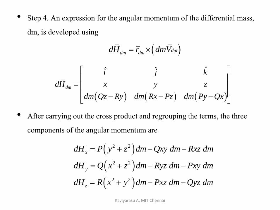
• Step 4. An expression for the angular momentum of the differential mass, dm, is developed using
• After carrying out the cross product and regrouping the terms, the three components of the angular momentum are
dmdm dmdH r dmV
ˆˆ ˆ
dm
i j k
dH x y z
dm Qz Ry dm Rx Pz dm Py Qx
2 2
2 2
2 2
x
y
z
dH P y z dm Qxy dm Rxz dm
dH Q x z dm Ryz dm Pxy dm
dH R x y dm Pxz dm Qyz dm
Kaviyarasu A, MIT Chennai
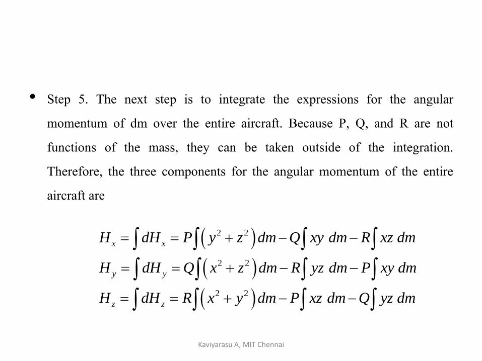
• Step 5. The next step is to integrate the expressions for the angularmomentum of dm over the entire aircraft. Because P, Q, and R are notfunctions of the mass, they can be taken outside of the integration.Therefore, the three components for the angular momentum of the entireaircraft are
2 2
2 2
2 2
x x
y y
z z
H dH P y z dm Q xy dm R xz dm
H dH Q x z dm R yz dm P xy dm
H dH R x y dm P xz dm Q yz dm
Kaviyarasu A, MIT Chennai

• The moments of inertia are indications of the resistance to rotation aboutthat axis (i.e, Ixx indicates the resistance to rotation about the x axis of theaircraft).
2 2
2 2
2 2
xx
yy
zz
I y z dm
I x z dm
I x y dm
The moment of inertia are defined as
Kaviyarasu A, MIT Chennai

• The products of inertia are an indication of the symmetry of the aircraft.Substituting the moments and products of inertia
xy
xz
yz
I xy dm
I xz dm
I yz dm
x xx xy xz
y yy yz xy
z zz xz yz
H PI QI RI
H QI RI PI
H RI PI QI
The product of inertia are
Kaviyarasu A, MIT Chennai

• This can also be easily found by applying an expression for angularmomentum usually developed in basic physics courses, which is
• Where is the aircraft’s inertia tensor and omega is the aircraft’s angular rate. The inertia tensor for an aircraft is
ˆˆ ˆx y zH H i H j H k
H I
xx xy xz
xy yy yz
xz yz zzBody
I I I
I I I I
I I I
I
Kaviyarasu A, MIT Chennai

xx xy xz
B xy yy yz
xz yz zzBody
I I I P
H I I I Q
I I I R
x xx xy xz
y yy yz xy
z zz xz yz
H PI QI RI
H QI RI PI
H RI PI QI
Kaviyarasu A, MIT Chennai

.xy yz
If the aircraft is assumed to have an xz plane of symmetry
the I and I products of inertia are zero
.
An aircraft has an xz plane of symmetry when the left side of the
aircraft is a mirror image of the right side about the xz plane
Kaviyarasu A, MIT Chennai

0xzI xz dm 0xyI xy dm 0yzI yz dm
Aircraft product of inertia
.
xz
xy yz
The I in the first figure not necessarily zero because the aircraft is not symmetrical
from top to bottom about the xz plane
Notice for I and I the reflection plane symmetry between quadrants I and IVand
.
.
, .xz
II and III
This leads to a zero value for both products of inertia Also notice that we do not
have reflection plane symmetry for the case of I therefore it has a nonzero value
Kaviyarasu A, MIT Chennai
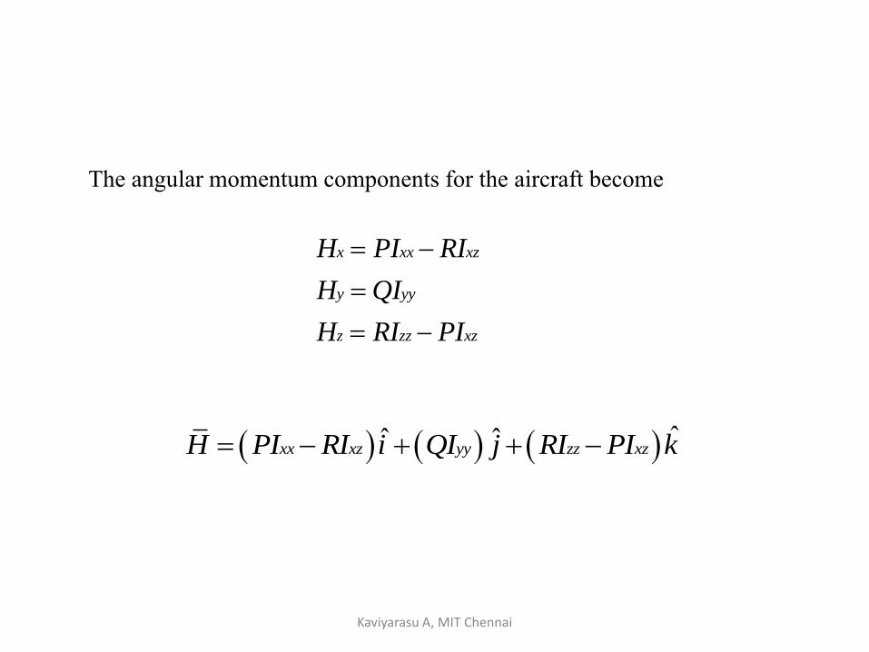
The angular momentum components for the aircraft become
x xx xz
y yy
z zz xz
H PI RI
H QI
H RI PI
ˆˆ ˆxx xz yy zz xzH PI RI i QI j RI PI k
Kaviyarasu A, MIT Chennai

• Step 6. After the angular momentum vector of the aircraft has beendetermined, the final step is to take the time rate of change of the angularmomentum vector with respect to inertial space but represented in theaircraft body axis system. The same relationship used in developing theacceleration with respect to an inertial reference frame from the forceequations can be used, namely
body body
Inertial body
dH dHH
dt dt
xx xz xx xz
yy yy
bodyzz xz zz xz
body
PI RI PI RIdH
QI QIdt
RI PI RI PI
Kaviyarasu A, MIT Chennai

• Assuming that the mass distribution of the aircraft is constant, such asneglecting fuel slosh, the moments and products of inertia do not changewith time
xx xz
yy
bodyzz xz
body
PI RIdH
QIdt
RI PI
body
xx xz yy zz xzbody
i j k
H P Q R
PI RI QI RI PI
,. xx yy zzi e I I and I are all zero
Kaviyarasu A, MIT Chennai

• Grouping terms yields
zz xz yy
xx xz zz xzbody
yy xx xzbody
Q RI PI RQI
H R PI RI P RI PI
PQI Q PI RI
2 2
xx zz yy xz
yy zz xx xz
Inertialbody
zz yy xx xzbody
PI QR I I R PQ I
dHQI PR I I P R I
dt
RI PQ I I QP P I
Kaviyarasu A, MIT Chennai
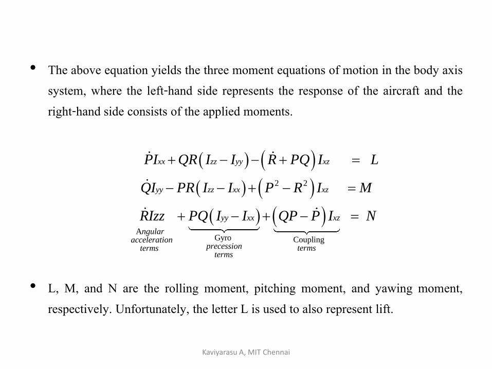
• The above equation yields the three moment equations of motion in the body axissystem, where the left-hand side represents the response of the aircraft and theright-hand side consists of the applied moments.
• L, M, and N are the rolling moment, pitching moment, and yawing moment,respectively. Unfortunately, the letter L is used to also represent lift.
2 2
A Gyro Coupling
xx zz yy xz
yy zz xx xz
yy xx xz
ngularacceleration
precession termstermsterms
PI QR I I R PQ I L
QI PR I I P R I M
RIzz PQ I I QP P I N
Kaviyarasu A, MIT Chennai

Thank you
Kaviyarasu A, MIT Chennai