
AIRCRAFT EMERGENCY LOCATOR …pointerinc.com/pdf/8000.pdfAIRCRAFT EMERGENCY LOCATOR TRANSMITTER...
16
AIRCRAFT EMERGENCY LOCATOR TRANSMITTER OPERATION AND INSTALLATION INSTRUCTIONS FOR MODEL 8000-1 (AF) FOR HORIZONTAL MOUNTING IN FIXED WING AIRCRAFT OR ANGULAR MOUNTING IN ROTARY WING AIRCRAFT TSO-C126A WARNING! FOR AVIATION EMERGENCY USE ONLY. UNAUTHORIZED OPERATION PROHIBITED.
Transcript of AIRCRAFT EMERGENCY LOCATOR …pointerinc.com/pdf/8000.pdfAIRCRAFT EMERGENCY LOCATOR TRANSMITTER...
AIRCRAFT EMERGENCY LOCATOR TRANSMITTER
OPERATION AND INSTALLATION
INSTRUCTIONS FORMODEL 8000-1 (AF)
FOR HORIZONTAL MOUNTING IN FIXED WING AIRCRAFT OR ANGULAR MOUNTING IN ROTARY WING AIRCRAFT
TSO-C126A
WARNING!FOR AVIATION EMERGENCY USE ONLY.
UNAUTHORIZED OPERATION PROHIBITED.
CONTENTSSECTION 1 DESCRIPTION 2SECTION 2 DIGITAL MESSAGES 5SECTION 3 PRE-INSTALLATION 5SECTION 4 INSTALLATION INSTRUCTIONS 7SECTION 5 FUNCTIONAL TESTING 9SECTION 6 OPERATING INSTRUCTIONS 11SECTION 7 BATTERY INFORMATION AND REPLACEMENT 12SECTION 8 ENVIRONMENTAL AND PERFORMANCE DATA 17
SECTION 1DESCRIPTION
1.1 Pointer 8000-1 ELT is a self-contained Emergency Locator Transmitter capable of automatic or manual operation (AF).
1.2 Pointer 8000-1 ELT conforms to the new TSO-C126a Digital ELT specification. This requires that each ELT transmits a unique identifying message, greatly reducing the impact of false alarms which troubled previous AM 121.5 MHz ELT technology.
1.3 Pointer 8000-1 ELT is designed to withstand forced landing and crash environment conditions and survive in an operable condition. The highest quality materials and components have been selected for manufacturing to insure rugged, reliable equipment.
1.4 Automatic activation is accomplished by a deceleration sensing inertia switch. The inertia switch is designed to activate when the unit senses crash-specific longitudinal inertia forces as described in TSO-C126a.
NOTE: When properly installed, parallel to the line of flight, POINTER 8000-1 ELT will not activate due to turbulence, normal operation, or aerobatics.
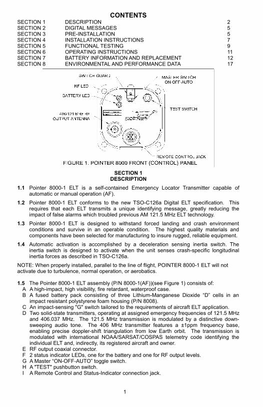
1.5 The Pointer 8000-1 ELT assembly (P/N 8000-1(AF))(see Figure 1) consists of:A A high-impact, high visibility, fire retardant, waterproof case.B A fused battery pack consisting of three Lithium-Manganese Dioxide “D” cells in an
impact resistant polystyrene foam housing (P/N 8008).C An impact-sensing "G" switch tailored to the requirements of aircraft ELT application.D Two solid-state transmitters, operating at assigned emergency frequencies of 121.5 MHz
and 406.037 MHz. The 121.5 MHz transmission is modulated by a distinctive down-sweeping audio tone. The 406 MHz transmitter features a ±1ppm frequency base, enabling precise doppler-shift triangulation from low Earth orbit. The transmission is modulated with international NOAA/SARSAT/COSPAS telemetry code identifying the individual ELT and, indirectly, its registered aircraft and owner.
E RF output coaxial connector.F 2 status indicator LEDs, one for the battery and one for RF output levels.G A Master “ON-OFF-AUTO” toggle switch.H A "TEST" pushbutton switch.I A Remote Control and Status-Indicator connection jack.
1
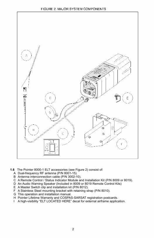
1.6 The Pointer 8000-1 ELT accessories (see Figure 2) consist of:A Dual-frequency RF antenna (P/N 8001-15).B Antenna interconnection cable (P/N 3002-10).C A Remote Control / Status Indicator Module and Installation Kit (P/N 8009 or 8019).D An Audio Warning Speaker (Included in 8009 or 8019 Remote Control Kits)E A Master Switch clip and installation kit (P/N 8012).F A Stainless Steel mounting bracket with retaining strap (P/N 8010).G This operation and installation manual.H Pointer Lifetime Warranty and COSPAS-SARSAT registration postcards.I A high-visibility “ELT LOCATED HERE” decal for external airframe application.
2
SECTION 2DIGITAL MESSAGES
2 ALL 406 MHz DIGITAL BEACONS MUST HAVE THEIR CURRENT OWNER, VESSEL, AND ID REGISTERED WITH THE INTERNATIONAL COSPAS/SARSAT AUTHORITY! This is normally done through a national body such as (in the U.S. & its territories) NOAA. These national bodies forward their beacon databases to COSPAS/SARSAT. U.S. registration may be accomplished on-line or mail/fax forms obtained at the www.sarsat.noaa.gov website. International registration may be accomplished through the appropriate national point-of-contact as listed on the cospas-sarsat.org website.
2.1 ELT Serial Number: The ELT manufacturer and serial number are encoded at the factory into the digital broadcast message as its unique ID. This is the default configuration of the POINTER 8000-1 ELT: nothing more need be done to use the ELT other than to register the ELT / aircraft / owner (with NOAA in the U.S.).
2.2 ELT Country Code: The default message is country-coded for the United States. If the aircraft is based outside the US, it should be coded with the national code of the country in which it is based. This should be the country registering the beacon with COSPAS/SARSAT. Contact Pointer for information on beacon country coding.
2.3 Other message types may be custom-programmed into the Pointer 8000-1 ELT, either on special order or by returning its Digital Control Module to the factory or distributor for reprogramming. Contact Pointer for additional information.
A Registration / Tail Number: An aircraft's national registration number may be programmed into the Pointer 8000-1 ELT.
B 24-bit Aircraft ID: The ICAO registry assigns a unique binary ID to each aircraft. This is used by navigation and ATC avionics and may also be used by the ELT.
C Operator-Serial Number: Fleet operators may have their designated ID and individual aircraft numbers encoded into their ELTs.
SECTION 3PRE-INSTALLATION
3 GENERALPointer 8000-1 ELT is designed to be installed in the aft section or cabin of the aircraft. Submission of FAA Field Approval Form 337 as required. The installation and testing should be made in accordance with FAA AC-43.13-2B by qualified personnel. Appropriate weight and balance computations shall be completed and entered in the Aircraft Logbook for each installation.
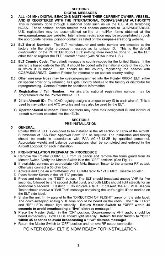
3.1 PRE-INSTALLATION PREPARATION PROCEDUCEA Remove the Pointer 8000-1 ELT from its carton and remove the foam guard from its
Master Switch. Verify the Master Switch is in the “OFF” position. (See Fig. 1).B If available, connect an appropriate 406 MHz Beacon Tester to the antenna RF output.
Otherwise connect a 50 ohm load.C Activate and tune an aircraft-band VHF COMM radio to 121.5 MHz. Disable squelch.D Place Master Switch in the “AUTO” position.E Press and release the "TEST" button. The ELT should broadcast analog VHF for five
seconds, followed by a ½ second digital burst, and both LEDs should light steadily for an additional 5 seconds. Flashing LEDs indicate a fault. If present, the 406 MHz Beacon Tester should receive a "Self-Test" message containing the unit's digital ID as marked on the ELT side label.
F Shake the unit firmly parallel to the “DIRECTION OF FLIGHT” arrow on the side label. The down-sweeping analog VHF tone should be heard on the radio. The "BATTERY" and "RF" LEDs should light steadily. Return Master Switch to "OFF" within 45 seconds to avoid broadcasting a “live” distress message!
G Place the Master Switch in the “ON” position. Down-sweeping VHF audio should be heard immediately. Both LEDs should light steadily. Return Master Switch to "OFF" within 45 seconds to avoid broadcasting a “live” distress message!
H Return the Master Switch to “OFF” position and remove RF output connection.
POINTER 8000-1 ELT IS NOW READY FOR INSTALLATION.
3
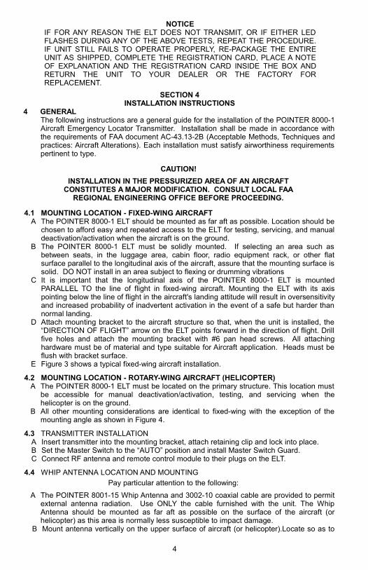
NOTICEIF FOR ANY REASON THE ELT DOES NOT TRANSMIT, OR IF EITHER LED FLASHES DURING ANY OF THE ABOVE TESTS, REPEAT THE PROCEDURE. IF UNIT STILL FAILS TO OPERATE PROPERLY, RE-PACKAGE THE ENTIRE UNIT AS SHIPPED, COMPLETE THE REGISTRATION CARD, PLACE A NOTE OF EXPLANATION AND THE REGISTRATION CARD INSIDE THE BOX AND RETURN THE UNIT TO YOUR DEALER OR THE FACTORY FOR REPLACEMENT.
SECTION 4INSTALLATION INSTRUCTIONS
4 GENERALThe following instructions are a general guide for the installation of the POINTER 8000-1 Aircraft Emergency Locator Transmitter. Installation shall be made in accordance with the requirements of FAA document AC-43.13-2B (Acceptable Methods, Techniques and practices: Aircraft Alterations). Each installation must satisfy airworthiness requirements pertinent to type.
CAUTION!
INSTALLATION IN THE PRESSURIZED AREA OF AN AIRCRAFT CONSTITUTES A MAJOR MODIFICATION. CONSULT LOCAL FAA
REGIONAL ENGINEERING OFFICE BEFORE PROCEEDING.
4.1 MOUNTING LOCATION - FIXED-WING AIRCRAFTA The POINTER 8000-1 ELT should be mounted as far aft as possible. Location should be
chosen to afford easy and repeated access to the ELT for testing, servicing, and manual deactivation/activation when the aircraft is on the ground.
B The POINTER 8000-1 ELT must be solidly mounted. If selecting an area such as between seats, in the luggage area, cabin floor, radio equipment rack, or other flat surface parallel to the longitudinal axis of the aircraft, assure that the mounting surface is solid. DO NOT install in an area subject to flexing or drumming vibrations
C It is important that the longitudinal axis of the POINTER 8000-1 ELT is mounted PARALLEL TO the line of flight in fixed-wing aircraft. Mounting the ELT with its axis pointing below the line of flight in the aircraft's landing attitude will result in oversensitivity and increased probability of inadvertent activation in the event of a safe but harder than normal landing.
D Attach mounting bracket to the aircraft structure so that, when the unit is installed, the “DIRECTION OF FLIGHT” arrow on the ELT points forward in the direction of flight. Drill five holes and attach the mounting bracket with #6 pan head screws. All attaching hardware must be of material and type suitable for Aircraft application. Heads must be flush with bracket surface.
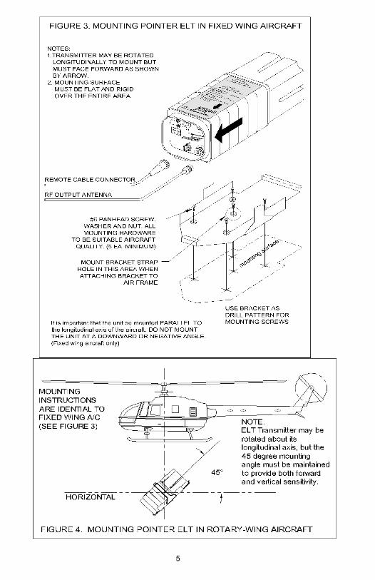
E Figure 3 shows a typical fixed-wing aircraft installation.
4.2 MOUNTING LOCATION - ROTARY-WING AIRCRAFT (HELICOPTER)A The POINTER 8000-1 ELT must be located on the primary structure. This location must
be accessible for manual deactivation/activation, testing, and servicing when the helicopter is on the ground.
B All other mounting considerations are identical to fixed-wing with the exception of the mounting angle as shown in Figure 4.
4.3 TRANSMITTER INSTALLATIONA Insert transmitter into the mounting bracket, attach retaining clip and lock into place.B Set the Master Switch to the “AUTO” position and install Master Switch Guard.C Connect RF antenna and remote control module to their plugs on the ELT.
4.4 WHIP ANTENNA LOCATION AND MOUNTING
Pay particular attention to the following:
A The POINTER 8001-15 Whip Antenna and 3002-10 coaxial cable are provided to permit external antenna radiation. Use ONLY the cable furnished with the unit. The Whip Antenna should be mounted as far aft as possible on the surface of the aircraft (or helicopter) as this area is normally less susceptible to impact damage.
B Mount antenna vertically on the upper surface of aircraft (or helicopter).Locate so as to
4
5
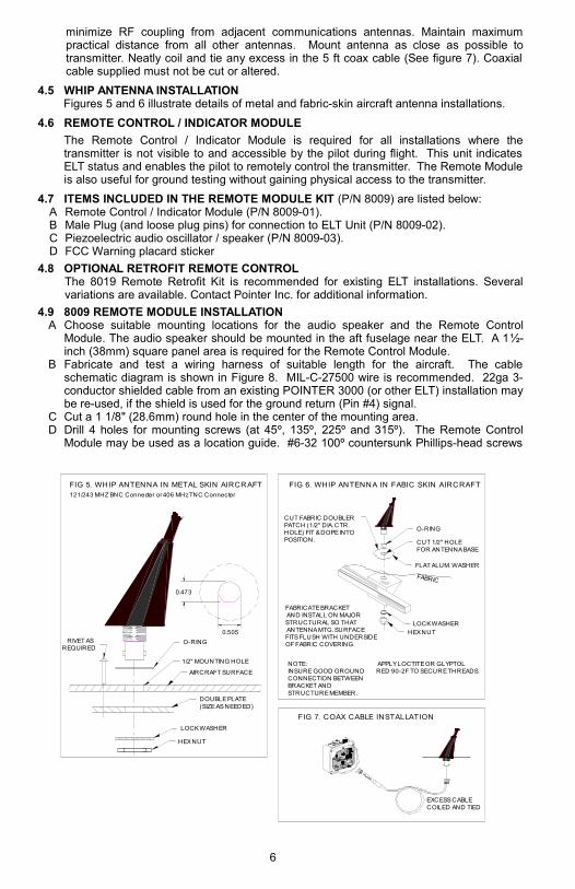
minimize RF coupling from adjacent communications antennas. Maintain maximum practical distance from all other antennas. Mount antenna as close as possible to transmitter. Neatly coil and tie any excess in the 5 ft coax cable (See figure 7). Coaxial cable supplied must not be cut or altered.
4.5 WHIP ANTENNA INSTALLATIONFigures 5 and 6 illustrate details of metal and fabric-skin aircraft antenna installations.
4.6 REMOTE CONTROL / INDICATOR MODULE
The Remote Control / Indicator Module is required for all installations where the transmitter is not visible to and accessible by the pilot during flight. This unit indicates ELT status and enables the pilot to remotely control the transmitter. The Remote Module is also useful for ground testing without gaining physical access to the transmitter.
4.7 ITEMS INCLUDED IN THE REMOTE MODULE KIT (P/N 8009) are listed below:A Remote Control / Indicator Module (P/N 8009-01). B Male Plug (and loose plug pins) for connection to ELT Unit (P/N 8009-02).C Piezoelectric audio oscillator / speaker (P/N 8009-03).D FCC Warning placard sticker
4.8 OPTIONAL RETROFIT REMOTE CONTROLThe 8019 Remote Retrofit Kit is recommended for existing ELT installations. Several variations are available. Contact Pointer Inc. for additional information.
4.9 8009 REMOTE MODULE INSTALLATIONA Choose suitable mounting locations for the audio speaker and the Remote Control
Module. The audio speaker should be mounted in the aft fuselage near the ELT. A 1½-inch (38mm) square panel area is required for the Remote Control Module.
B Fabricate and test a wiring harness of suitable length for the aircraft. The cable schematic diagram is shown in Figure 8. MIL-C-27500 wire is recommended. 22ga 3-conductor shielded cable from an existing POINTER 3000 (or other ELT) installation may be re-used, if the shield is used for the ground return (Pin #4) signal.
C Cut a 1 1/8" (28.6mm) round hole in the center of the mounting area.D Drill 4 holes for mounting screws (at 45º, 135º, 225º and 315º). The Remote Control
Module may be used as a location guide. #6-32 100º countersunk Phillips-head screws
6
1/2" MOUNTING HOLE
FIG 5. WHIP ANTENNA IN METAL SKIN AIRCRAFT121/243 MHZ BNC Connecter or 406 MHz TNC Connecter
FIG 6. WHIP ANTENNA IN FABIC SKIN AIRCRAFT
HEX NUT
O-RING
LOCK WASHER
DOUBLE PLATE(SIZE AS NEEDED)
RIVET ASREQUIRED
AIRCRAFT SURFACE
0.473
0.505
O-RING
FLAT ALUM. WASHER
FABRIC
HEX NUT
LOCK WASHER
CUT 1/2" HOLEFOR ANTENNA BASE
CUT FABRIC DOUBLERPATCH (1/2" DIA. CTR.HOLE) FIT & DOPE INTOPOSITION.
FABRICATE BRACKETAND INSTALL ON MAJORSTRUCTURAL SO THATANTENNA MTG. SURFACEFITS FLUSH WITH UNDERSIDEOF FABRIC COVERING.
NOTE:INSURE GOOD GROUND CONNECTION BETWEEN BRACKET AND STRUCTURE MEMBER.
APPLY LOCTITE OR GLYPTOL RED 90-2F TO SECURE THREADS.
FIG 7. COAX CABLE INSTALLATION
EXCESS CABLE COILED AND TIED
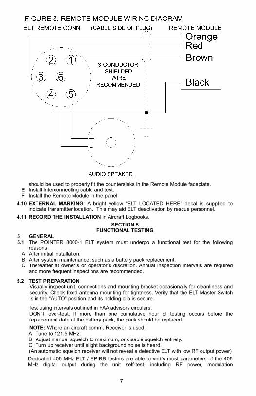
should be used to properly fit the countersinks in the Remote Module faceplate.E Install interconnecting cable and test.F Install the Remote Module in the panel.
4.10 EXTERNAL MARKING: A bright yellow “ELT LOCATED HERE” decal is supplied to indicate transmitter location. This may aid ELT deactivation by rescue personnel.
4.11 RECORD THE INSTALLATION in Aircraft Logbooks.
SECTION 5FUNCTIONAL TESTING
5 GENERAL5.1 The POINTER 8000-1 ELT system must undergo a functional test for the following
reasons:A After initial installation.B After system maintenance, such as a battery pack replacement.C Thereafter at owner’s or operator’s discretion. Annual inspection intervals are required
and more frequent inspections are recommended.
5.2 TEST PREPARATIONVisually inspect unit, connections and mounting bracket occasionally for cleanliness and security. Check fixed antenna mounting for tightness. Verify that the ELT Master Switch is in the “AUTO” position and its holding clip is secure.
Test using intervals outlined in FAA advisory circulars.DON’T over-test. If more than one cumulative hour of testing occurs before the replacement date of the battery pack, the pack should be replaced.
NOTE: Where an aircraft comm. Receiver is used:A Tune to 121.5 MHz.B Adjust manual squelch to maximum, or disable squelch entirely.C Turn up receiver until slight background noise is heard.(An automatic squelch receiver will not reveal a defective ELT with low RF output power)
Dedicated 406 MHz ELT / EPIRB testers are able to verify most parameters of the 406 MHz digital output during the unit self-test, including RF power, modulation
7
characteristics, and the digital ID code. The ID code must match the "15Hex" ID printed on the ELT's external labeling and registered with the international COSPAS / SARSAT authority.
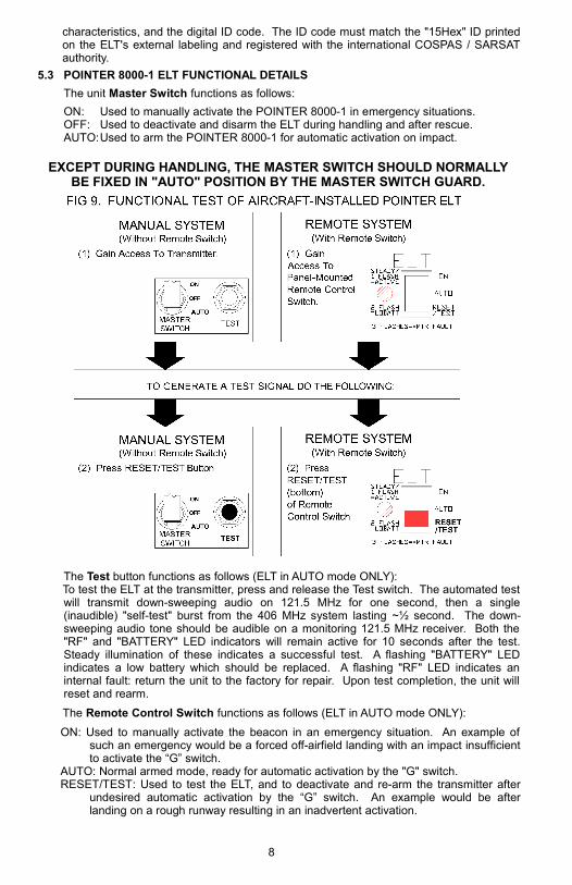
5.3 POINTER 8000-1 ELT FUNCTIONAL DETAILS
The unit Master Switch functions as follows:
ON: Used to manually activate the POINTER 8000-1 in emergency situations.OFF: Used to deactivate and disarm the ELT during handling and after rescue.AUTO:Used to arm the POINTER 8000-1 for automatic activation on impact.
EXCEPT DURING HANDLING, THE MASTER SWITCH SHOULD NORMALLY BE FIXED IN "AUTO" POSITION BY THE MASTER SWITCH GUARD.
The Test button functions as follows (ELT in AUTO mode ONLY):To test the ELT at the transmitter, press and release the Test switch. The automated test will transmit down-sweeping audio on 121.5 MHz for one second, then a single (inaudible) "self-test" burst from the 406 MHz system lasting ~½ second. The down-sweeping audio tone should be audible on a monitoring 121.5 MHz receiver. Both the "RF" and "BATTERY" LED indicators will remain active for 10 seconds after the test. Steady illumination of these indicates a successful test. A flashing "BATTERY" LED indicates a low battery which should be replaced. A flashing "RF" LED indicates an internal fault: return the unit to the factory for repair. Upon test completion, the unit will reset and rearm.
The Remote Control Switch functions as follows (ELT in AUTO mode ONLY):
ON: Used to manually activate the beacon in an emergency situation. An example of such an emergency would be a forced off-airfield landing with an impact insufficient to activate the “G” switch.
AUTO: Normal armed mode, ready for automatic activation by the "G" switch.RESET/TEST: Used to test the ELT, and to deactivate and re-arm the transmitter after
undesired automatic activation by the “G” switch. An example would be after landing on a rough runway resulting in an inadvertent activation.
8
The single LED on the Remote Module replaces both local LEDs by lighting steadily for a successful test, flashing single pulses for normal (manual or automatic) activation, flashing double pulses for a low battery, flashing triple pulses to indicate low 121.5 radiation and flashing quadruple pulses to indicate low 406 output.
5.4 MAINTENANCEIf the ELT fails to operate properly during testing, remove only the main unit and return it to the manufacturer for inspection and repair. Remove the battery pack (and its housing) before shipping (refer to Section 7) to avoid inadvertent transmission, hazardous material shipment premiums, and to reduce the unit's (weight-based) shipping cost.
SECTION 6OPERATING INSTRUCTIONS
6 GENERALYour POINTER 8000-1 ELT has been engineered to provide the most reliable operation possible. Every contingency has been considered in the design and construction of the POINTER 8000-1 ELT system. The following section will acquaint you with the simple operational procedures of the POINTER 8000-1 ELT. It is recommended that you familiarize yourself thoroughly with these procedures and have them firmly in mind to add to your flying confidence.
6.1 It is recommended that the following steps be taken to insure the best possible operation in an emergency.
A Become thoroughly familiar with the POINTER ELT instructions.B Keep them on hand in the aircraft at all times.C Visually inspect the unit at regular intervals for cleanliness and security. Check external
antenna mounting and cable connections for tightness.
6.2 OPERATING MODE POINTER ELT INSTALLED IN AIRCRAFTA After a forced landing, if the aircraft's COM receiver is operable, listen on 121.5 MHz for
audio transmissions. Ensure that external antenna is clear of obstructions.B The range of the POINTER 8000-1 ELT varies according to signal type, weather, and
topography. The 406 MHz digital signal is intended to be received by satellites in both low (LEOS) and geosynchronous (GEOS) orbits. Depending on terrain, the 121.5 MHz swept audio homing signal may be heard up to 30 miles by a search aircraft at 10,000 ft. Stay close to the downed aircraft to permit easier spotting by airborne searchers.
The following table gives the switch positions and functions for various situations.
MANUAL ACTIVATION: Via Local Switches on POINTER 8000-1 ELT
MODE Switch Position FUNCTIONAUTO/ARM
“AUTO” (Normal Flight Setting)
ELT "armed" and automatically activated if “G” switch senses predetermined deceleration level.
MANUAL ON
“ON” Overrides “G” Switch and activates ELT manually if pilot wishes to activate ELT prior to imminent
emergency situation.OFF/ DISARM
“OFF” Deactivates POINTER ELT in preparation for removal from aircraft or to discontinue signal after rescue.
TEST Press and release "TEST" pushbutton
11-second single-burst "self- test" may be performed on the ground or in flight.
REMOTE ACTIVATION: Via Remote Module on Instrument Panel
Master Switch on Transmitter
Remote Switch on Control Panel
FUNCTION
“AUTO” “AUTO” (Normal Flight Setting)
ELT automatically activated if “G” switch senses predetermined deceleration level.
“AUTO” “ON” Overrides “G” Switch and turns ELT on so it can be tested for proper operation on the ground
---- OR ----If emergency situation is imminent and pilot wishes to activate ELT prior to emergency
9
“AUTO” Press and release “RESET/TEST” (momentary)
If inadvertent activation occurs in system, the transmitter can be restored to “ARMED” status by momentarily pressing "RESET/TEST.”
“AUTO” Press and release “RESET/TEST"
11-second single-burst “self-test” may be performed on the ground or in flight.
SECTION 7BATTERY INFORMATION AND REPLACEMENT
7 GENERALPower is supplied by a safety-fused, impact-resistant molded polystyrene foam battery pack containing three 3V Lithium-Manganese Dioxide “D” size batteries in series. Fresh battery open-circuit voltage is 9.3 volts. Nominal output under load is 7.5 volts.
7.1 WHEN TO REPLACE BATTERY PACKIn accordance with FAA regulations, batteries must be replaced at the following times:
A After five years from its imprinted date of manufacture. This replacement date is imprinted on the battery pack and also on an external label.
B After the transmitter has been used in an emergency situation (including any inadvertent activation of unknown duration).
C After the transmitter has been operated for more than one cumulative hour (e.g. time accumulated in several tests and an inadvertent activation of known duration).
Check with your local dealer or distributor for approved replacement battery packs.
WARNING: DO NOT ATTEMPT TO RECHARGE THE BATTERY PACK!PACK IS FUSE-PROTECTED. DO NOT SHORT-CIRCUIT!
7.2 REMOVING THE TRANSMITTER FROM AIRCRAFTTransmitter must be removed from the aircraft for battery replacement:
A Remove the Switch Guard and place the Master Switch in the “OFF” position.B Disconnect the antenna cable and the Remote Module connector.C Open latch on the hold-down strap and remove the transmitter from the mounting
bracket.
7.3 REPLACE BATTERY PACK AS FOLLOWS (See Figure 10):A Remove (and retain) four screws from back of ELT.B Slide battery housing back (save gasket), and disconnect the transmitter connector (6
leads) by carefully depressing the release latch on the connector.C Disconnect the battery connector (2 leads) from the G-Switch P.C.B. by carefully
depressing the release latch on the connector.D Remove (and retain) the five screws attaching G-Switch board to the housing.E Remove and replace the battery pack.F Reverse steps A-D to reassemble the POINTER 8000-1 ELT.G Exercise care not to over tighten the circuit board screws during reassembly.H Exercise care to insure that the O-ring gasket is completely contained within its channel.
7.4 Apply new battery replacement date label, supplied with replacement pack, on battery case back prior to re-installing transmitter in aircraft.
7.5 Reverse step 7.2 to reinstall transmitter in aircraft.7.6 Test in accordance with Section 3.1 and Section 5.2: Function testing.
10
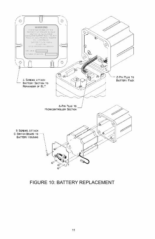
FIGURE 10: BATTERY REPLACEMENT
11

THIS PAGE INTENTIONALLY LEFT BLANK
12
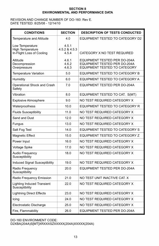
SECTION 8ENVIRONMENTAL AND PERFORMANCE DATA
REVISION AND CHANGE NUMBER OF DO-160: Rev E.DATE TESTED: 8/25/08 - 12/14/10
CONDITIONS SECTION DESCRIPTION OF TESTS CONDUCTED
Temperature and Altitude
Low TemperatureHigh TemperatureIn-Flight Loss of Cooling
AltitudeDecompressionOverpressure
4.0
4.5.14.5.2 & 4.5.3
4.5.4
4.6.14.6.24.6.3
EQUIPMENT TESTED TO CATEGORY D2
CATEGORY X NO TEST REQUIRED
EQUIPMENT TESTED PER DO-204AEQUIPMENT TESTED PER DO-204AEQUIPMENT TESTED TO CATEGORY
Temperature Variation 5.0 EQUIPMENT TESTED TO CATEGORY B
Humidity 6.0 EQUIPMENT TESTED TO CATEGORY A
Operational Shock and Crash Safety
7.0 EQUIPMENT TESTED PER DO-204A
Vibration 8.0 EQUIPMENT TESTED TO CAT. S(MT)
Explosive Atmosphere 9.0 NO TEST REQUIRED CATEGORY X
Waterproofness 10.0 EQUIPMENT TESTED TO CATEGORY R
Fluids Susceptibility 11.0 NO TEST REQUIRED CATEGORY X
Sand and Dust 12.0 NO TEST REQUIRED CATEGORY X
Fungus 13.0 NO TEST REQUIRED CATEGORY X
Salt Fog Test 14.0 EQUIPMENT TESTED TO CATEGORY S
Magnetic Effect 15.0 EQUIPMENT TESTED TO CATEGORY Z
Power Input 16.0 NO TEST REQUIRED CATEGORY X
Voltage Spike 17.0 NO TEST REQUIRED CATEGORY X
Audio Frequency Susceptibility
18.0 NO TEST REQUIRED CATEGORY X
Induced Signal Susceptibility 19.0 NO TEST REQUIRED CATEGORY X
Radio Frequency Susceptibility
20.0 EQUIPMENT TESTED PER DO-204A
Radio Frequency Emission 21.0 NO TEST UNIT INACTIVE CAT. X
Lighting Induced Transient Susceptibility
22.0 NO TEST REQUIRED CATEGORY X
Lightning Direct Effects 23.0 NO TEST REQUIRED CATEGORY X
Icing 24.0 NO TEST REQUIRED CATEGORY X
Electrostatic Discharge 25.0 NO TEST REQUIRED CATEGORY X
Fire, Flammability 26.0 EQUIPMENT TESTED PER DO-204A
DO-160 ENVIRONMENT CODE:D2XBA(204A)S[MT]XRXXXSZXXXXX(204A)XXXXX(204A)
13
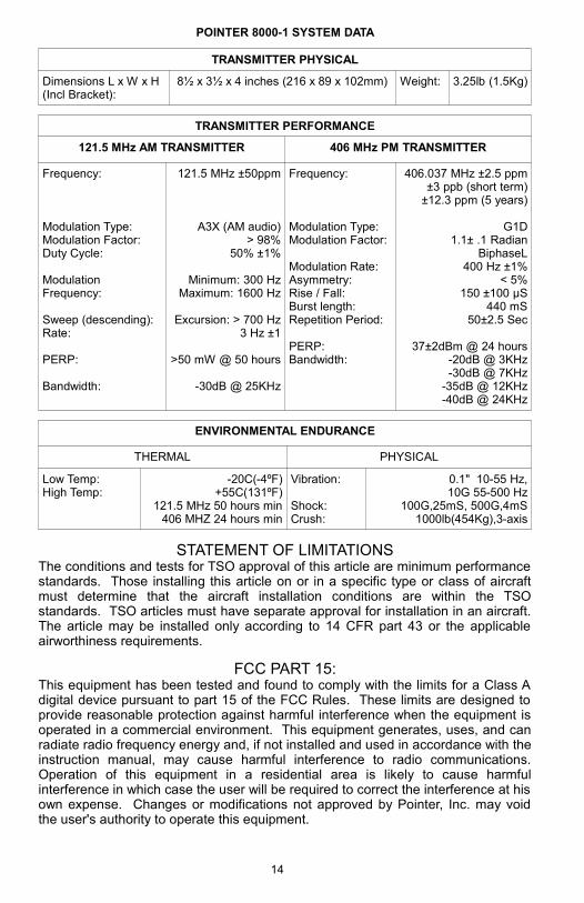
POINTER 8000-1 SYSTEM DATA
TRANSMITTER PHYSICAL
Dimensions L x W x H (Incl Bracket):
8½ x 3½ x 4 inches (216 x 89 x 102mm) Weight: 3.25lb (1.5Kg)
TRANSMITTER PERFORMANCE
121.5 MHz AM TRANSMITTER 406 MHz PM TRANSMITTER
Frequency:
Modulation Type:Modulation Factor:Duty Cycle:
Modulation Frequency:
Sweep (descending):Rate:
PERP:
Bandwidth:
121.5 MHz ±50ppm
A3X (AM audio)> 98%
50% ±1%
Minimum: 300 HzMaximum: 1600 Hz
Excursion: > 700 Hz3 Hz ±1
>50 mW @ 50 hours
-30dB @ 25KHz
Frequency:
Modulation Type:Modulation Factor:
Modulation Rate:Asymmetry:Rise / Fall:Burst length:Repetition Period:
PERP:Bandwidth:
406.037 MHz ±2.5 ppm±3 ppb (short term)
±12.3 ppm (5 years)
G1D1.1± .1 Radian
BiphaseL400 Hz ±1%
< 5%150 ±100 µS
440 mS50±2.5 Sec
37±2dBm @ 24 hours-20dB @ 3KHz-30dB @ 7KHz
-35dB @ 12KHz-40dB @ 24KHz
ENVIRONMENTAL ENDURANCE
THERMAL PHYSICAL
Low Temp: High Temp:
-20C(-4ºF)+55C(131ºF)
121.5 MHz 50 hours min406 MHZ 24 hours min
Vibration:
Shock:Crush:
0.1" 10-55 Hz,10G 55-500 Hz
100G,25mS, 500G,4mS1000lb(454Kg),3-axis
STATEMENT OF LIMITATIONSThe conditions and tests for TSO approval of this article are minimum performance standards. Those installing this article on or in a specific type or class of aircraft must determine that the aircraft installation conditions are within the TSO standards. TSO articles must have separate approval for installation in an aircraft. The article may be installed only according to 14 CFR part 43 or the applicable airworthiness requirements.
FCC PART 15:This equipment has been tested and found to comply with the limits for a Class A digital device pursuant to part 15 of the FCC Rules. These limits are designed to provide reasonable protection against harmful interference when the equipment is operated in a commercial environment. This equipment generates, uses, and can radiate radio frequency energy and, if not installed and used in accordance with the instruction manual, may cause harmful interference to radio communications. Operation of this equipment in a residential area is likely to cause harmful interference in which case the user will be required to correct the interference at his own expense. Changes or modifications not approved by Pointer, Inc. may void the user's authority to operate this equipment.
14
15
WARRANTY
POINTER, INC warrants each new Pointer Emergency Locater Transmitter to be free of defects in material and workmanship, to the original purchaser, indefinitely, provided the unit is equipped with a POINTER, Inc. manufactured battery pack. The company will repair or replace, free of charge, at its factory, any part or parts found to be defective under normal use and service – PROVIDED that the enclosed warranty card is properly completed and mailed within 15 days after installation and is on file with POINTER. This warranty does not cover shipping cost or removal and re-installation of the unit in the aircraft.
This warranty does not cover defects resulting from alterations, improper use or installation, tampering or failure of the purchaser to follow normal operating procedures outlined in the user’s instructions, nor for example, does it cover damage resulting from acts of God, such as floods, tornadoes, or lightning.
This warranty is made only to original purchasers in the United States and does not cover the responsibility for the shipping expenses in returning the transmitter or accessory to POINTER or return to the purchaser.
THE WARRANTY PROVISIONS SET FORTH ABOVE ARE IN LIEU OF ANY AND ALL OTHER WARRANTY, WHETHER EXPRESSED OR IMPLIED, INCLUDING THE WARRANTIES OF MERCHANTABILITY OR FITNESS FOR A PARTICLUAR PURPOSE, AND ANY OTHER OBLIGATIONS OR LIABILITY WHATSOEVER ON THE PART OF POINTER, INC. OR ANY OF ITS FRANCHISED DEALERS.
NOTICE
The preceding instructions are a general guide for the installation of Pointer Automatic Emergency Locator Transmitters. Installation should be made in accordance with FAA installation requirements by an approved installation facility.
MFG. BY POINTER, INC.1027 NORTH STADEM DRIVE
TEMPE, ARIZONA 85281
20150706.2004