
Aircraft detection system from the 1920s.
114
1
Transcript of Aircraft detection system from the 1920s.

1

Aircraft detection system from the 1920s.

3
I’ll discuss the following antennas today. I won’t be talking
about arrays of verticals, or the new Shared Apex Loop - There
are many specialized RX antennas out there, and I can’t cover
them all today!
George VY2GF asked me to deliver this presentation on receive
antennas. I found a picture of George when he was a young
Ham….

4
This is Harold H. Beverage at his Amateur Radio Station. Possibly at the
University of Maine around 1915.
Most people think of Beverage antennas when they think of lowband
receive antennas, but as we’ll see today, there are others out there that
offer good performance, even on small city lots.

5
For a transmit antenna, we want maximum possible field
strength in a given direction (or directions) at the most
useful elevation (wave) angles. We cannot tolerate
unnecessary power loss in a transmit antenna, because any
amount of transmitting loss decreases signal-to-noise ratio
at the distant receiver. Antenna efficiency is an important
issue for transmitting. It is obvious that for a given
elevation angle and direction the highest gain antenna will
deliver the strongest signal to the target area. We really do
not care if we are being heard in other directions (areas) or
not, we are only interested in the target direction.
A receiving antenna on the other hand has a different
design priority. The goal is obtaining a signal that can be
read comfortably, which means having the minimum
possible amount of QRM and noise. The important issue
when receiving is signal-to-noise ratio (S/N). The
receiving antenna providing the best performance can and
will be different under different circumstances, even at the
same or similar locations. There is no such thing as a
universal “best low-band receiving antenna.”
An example might better illustrate the concept:

6

7

8

9
There are a few things we have to keep in mind:
1.) If noise is not evenly distributed (which is often the case) performance will
depend on the gain difference between desired signal direction (azimuth and
elevation) to gain in the direction of noise(s). A 20dB null on the noise
compared to gain in the desired signal direction will actually improve S/N
ratio by 20 dB, if the noise from the null direction totally dominates all other
noises.
2.) If noise arrives primarily from the same direction and angle as the desired
signal (and assuming polarization of signals and noise is the same), there will
be no S/N improvement.
3.) If noise originates in the near field of the antenna, all bets are off. Anything
can happen.

10

Antennas with a nominal gain of as low as –15 dBi will normally not
require a preamplifier, unless you live in a very quiet rural area and
have very long, lossy feed lines. That means that Beverages, even with
feed lines of many hundreds of meters long, will—as a rule—not require
a preamplifier. Unless of course you like to see you’re S-meter dancing
up and down like a yoyo. But signal readability has nothing to see with
dancing S-meter needles. It is only a question of signal-to-noise ratio.
But we have also seen receiving antennas such as loops with gains of –
30 dBi, and that is pretty low and does require some signal boosting.
How do you know if you need a preamplifier? The rule is simple. During
the quietest moment of the day (usually at noon on 160 meters), with
your receiver set at the narrowest bandwidth you normally use, can you
hear the noise go up significantly when you switch from a dummy load
to your receiving antenna? If you can, then you have enough gain in
your system.
If you hear the receiver’s internal noise and not band noise, then you
need a preamplifier. You have a problem because:
The antenna output might be extremely low (less than –15 dBi, for
example).
The feed line might be very long and/or lossy.
You need to compensate for filter losses, splitter losses etc.
As a rule you should keep the signal level as low as possible to prevent
chances of intermodulation and overload. This is also why our receivers
have a front-end-attenuator, as well as a switchable preamplifier.

MMICs have poor IMD performance and are also very poor with even-order harmonic distortion. They have a fixed gain, which is usually way too high anyhow. Last but not least, they withstand little abuse.
12

Larry, W7IUV, has published a 160-meter preamplifier design with excellent
characteristics. Go to his Web site (w7iuv.com) for further details on this very
popular amplifier. The design of this popular preamp changes as he discovers
ways to improve it. Please check his website for the latest information.

Sergio, IK4AUY, described an excellent preamplifier as part of his article “A
High Level Accessory Front End for the HF Amateur Bands” in Apr/March
2003 QEX . The schematic of his preamplifier is shown in Fig 7-157. The
performance data are just short of spectacular:
3rd order intercept (IP3): +43 dBm
1 dB compression: +24.5 dBm
Gain: 12 dB (1 to 30 MHz)
Noise figure: 3.9 dB at 30 MHz
14

15
While often attributed to charged particles
(such as water droplets) hitting an antenna,
most precipitation static is actually caused
by intense electric field gradients in the area
surrounding the antenna. Such conditions
commonly appear during inclement weather,
when movement of particles or moisture
causes concentrated areas of charges. The
strong electric fields are responsible for
noise-producing corona discharges. The
noise comes from low-current corona
discharges from sharp or protruding objects.
(St. Elmo’s Fire)
Using an antenna at a lower height reduces
corona current—The electric-field gradient is
smaller close to the wide smooth surface of
the earth. Vertical antennas are particularly
sensitive to precipitation static; they have
pointed ends protruding upwards towards
the oppositely charged sky.
Beverages on the other hand, being near
earth, will have fewer corona discharge
problems. They also have low surge
impedances. This means the low-current
high-voltage arcs transfer very little noise
power into the antenna. Beverages are thus

How many of you have built loop antennas for receive?

17
Unlike a large loop antenna (greater than 0.5 wavelength), a Receive Loop is
much smaller (most are less than 0.1 wavelength), and exhibits a much
different antenna pattern. RX Loops deliver strongest signals in the direction
of the plane of the loop, and sharp nulls broadside to that plane.
Signals broadside to the loop induce the same voltage throughout the wire of
the loop. Because all sections of the wire are at the same potential, no current
can flow. Signals off the ends of the loop induce different voltages in the loop
wire as they travel through it, allowing a current to flow.
The advantage of the RX Loop is the sharp null. Careful positioning can block
out an interfering signal or noise, and permit the desired signal to be heard.

18
A typical homebrew RX Loop. Note the use of a separate loop inside the main
winding. It presents a better impedance match to the receiver. It also prevents
the main loop from being too heavily loaded by the receiver. This would
destroy the Q of the circuit, allowing strong, off-frequency signals to enter the
receiver’s front end.

19
The presence of metal objects near a loop antenna can upset the balance of the
system, causing the null to “fill in”. This sort of distortion can eliminate the
advantage of an RX loop – the sharp null that can be used to block an
interfering signal or noise.

20
This can be eliminated by shielding the loop as shown. This ensures that the
loop remains balanced with respect to ground despite the presence of nearby
metal objects. It has nothing to do with receiving the magnetic component of
an EM wave – this is a common misconception! Check out the website of
W8JI (www.w8ji.com) for an in-depth explanation. In reality, the shield
becomes the actual antenna, not the wire inside the loop. There are many good
and bad ways to feed and shield an RX Loop. Points to remember:
•The shield is the actual antenna
•The shield must be perfectly symmetrical away from the inner wire exit point
•The gap in the shield must be exactly opposite the grounded point
•The ground must be at the inner wire exit point
•The shield will not make an unshielded loop that is properly balanced any
quieter
•The shield only is a tool to help you balance the system IF the shield is
properly implemented

21
RX Loops mounted in the shack can be tuned manually with variable
capacitors. Tuning remote loops can be more problematic. I have tried slow
speed electric motors to turn the variable capacitor. The electric noise from
the motor makes it difficult to peak the antenna. Varactor Diodes, which
exhibit a changing capacitance as the voltage is varied, can be used instead.
The voltage is fed up the coax, using a DC blocking capacitor to protect the
receiver.

22
You can use a feedback loop to increase the gain and the Q of the loop. This
circuit is essentially an Armstrong oscillator that doesn’t quite oscillate. The
signal provided by the feedback loop must be adjusted until the circuit is on
the verge of oscillating. At that point, the gain increases and the bandwidth
narrows. It takes some skill to use this type of RX Loop, but it is apparently
an excellent accessory. Some sort of potentiometer might be necessary to
better control the amount of feedback.

You can use a magnetic loop with a broadband current amplifier in lieu of the
usual resonating components. Jeff VE1ZAC built the loop seen here. His
antenna utilizes an aluminium 1 meter diameter loop with dual “Hoops” to
make it look fatter and attain a lower self-inductance. It measures at 1.48 uHy
which is apparently quite good for a loop like this. It is mounted on a 2 M
mast and sits on a TV rotator allowing remote control from inside the shack. It
uses two aluminum flat bars 3.1 meters long, 1 1/4″ wide and 1/8″ thick. 1 m
diam. L= 1.45 uH
inductance is critical. The ideal loop is fat with very low inductance. Fatter is
better, but it is not strictly necessary to have a full metal loop to get the
improved low inductance result. A second loop place parallel to the first and
offset by about 8” produces a lower inductance through mutual coupling.
The amplifier is built by LZ1AQ at Active Antennas. It actually has three
receive modes built in, all controlled from the remote shack end switches. You
can have one loop, a second crossed loop or other combinations. Plus, the built
in switching allows using your two loops, or one loop and a short wire as a
small dipole connected to a voltage amplifier. In Jeff’s case he used the loop
mast for the second element. It works very well. The entire system is well
made and arrived complete and intact in a timely fashion via airmail. The units
are checked out and adjusted before leaving Bulgaria, and there is excellent
documentation showing how to hookup and test the system. All connectors and
hardware are provided. You are responsible for the loop, some shielded CAT5
cable to hook the unit up, and a power supply. 23
24

25
Because of the poor sensitivity compared to many other RX antennas,
conventional RX Loops are probably better suited for SWL, Broadcast Band
and LF Beacon DX’ing, where signals are going to be stronger than on the
Amateur bands. The newer amplified broadband loops seem to offer better
performance, and may be worth checking out.

26

27
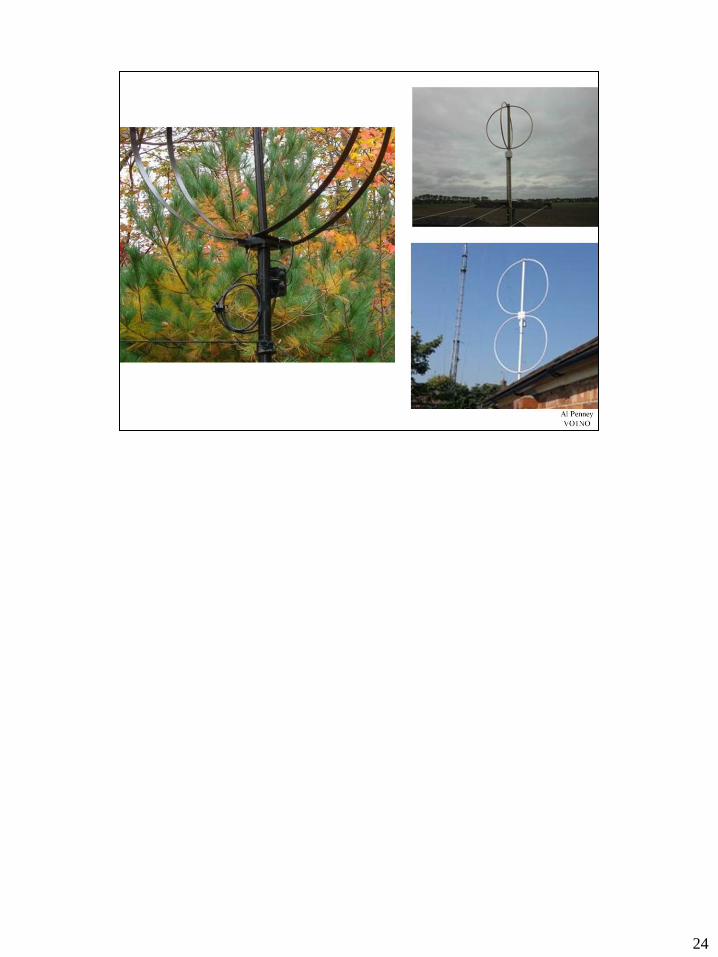
These elongated terminated loops are really a simple pair of verticals
with a horizontal feed line, one being basefed, the other being fed via
the top wire. That provides crossfire phasing. When the element
spacing is less than λ/4, this always fires towards the feed point end of
the array. When properly terminated the loops show nearly constant
current at all points on the loop. This constant current is achieved by
terminating the far end of the loop in the same impedance as the feed
point. Thus, the portions considered to be the vertical “elements” have
equal current, with a phase equal to 180° plus the electrical length of
the connecting wires, which is slightly more than the element spacing.
In other words, the terminated loop is like two constant current verticals
with classic end-fire phasing. The only difference is the horizontal
component in the radiation due to the radiating delay line (sloping or
horizontal) of the terminated loops. This is the operating principle for the
entire family of elongated terminated loops. Sloping (inclined) wires
used in some of the designs are just like a horizontal wire in
combination with a vertical wire, and the same reasoning as above can
be used.

28
Floyd Koontz, WA2WVL, is the originator of the EWE. His QST articles are must-reads
on this novel receiving antenna. Incidentally, the curious name “EWE” came about
because Floyd noted that his new antenna looked very much like an upside-down
letter “U.” He jokingly submitted a drawing of a female sheep—a ewe—to headline his
February 1995 QST article, which he impishly titled with the triple entendre “Is This
EWE for You?”
A EWE is small, requires little engineering, and can be designed to cover 80 and 160
meters. Moreover, the EWE is low profile and can be built for little money. In
appearance, the EWE resembles a very short Beverage, though in fact it as an array
of two short vertical antennas.
The horizontal wire is only about 5 to 15 meters long and is about 3 to 6 meters above
ground. In other words, an EWE can fit in many tiny yards. The original description by
WA2WVL uses 3-meter high “elements” with a spacing going from 4.5 to 18 meters,
depending on the band (80 or 160 meters).
A good rule of thumb is to build an EWE where the length is twice the height. This rule
can be followed for elements going from 3 to 6 meters in height, and will result in an
optimum termination resistance of approximately 1000 Ω for both bands. The smaller
the array, the easier it is to obtain a good deep null, but the lower the output level. The
larger versions will be near the cut-off frequency, where a deep null cannot be
obtained.
The output (gain) of the antenna depends on its size. The gain for 160 meters varies
typically between –20 dBi and –30 dBi over average ground, and is about 9 dB higher
on 80 meters. The inverted-V shaped EWEs looks quite attractive and can easily be
made into a “hand-rotatable” receiving antenna: Just walk out in the garden and
anchor the sloping wires to a different set of ground rods. It should be useful for
DXpeditions as well.
The value of the terminating resistor is quite critical if you want to obtain a good notch
in the back response. Since the ground resistance is part of the terminating resistance,
a good low-impedance, stable ground is required. The ground resistance of a single
ground rod may vary from as low as 50 Ω to as much as several hundred Ω. Although

29
Ewe Antenna at KC4HW
It has been reported that the best way to tune an array for best F/B is to
find a medium-wave BC transmitter in the back of the antenna. Using a
medium-wave signal during day time ensures that you will receive it on
ground-wave, and as such have a constant and stable signal source.
Tune the terminating resistor for a full notch, striving for a minimum of
25 dB. This value will be very close to the best value for 160 meters and
close to what’s best on 80 meters.
You should use broadcast stations between 1600 and 1700 kHz to do
the null adjustment if you can. It is impossible to reliably adjust the
termination resistance using signals arriving by skywave. You could also
use a nearby local ham (in-line off the back) or set up a small signal
generator off the back, using a small vertically polarized antenna, at a
distance of at least 1 λ from the EWE (which means outside its near
field).

30
A major drawback to the EWE is its extreme sensitivity to any change in
the local soil conductivity. EA3VY was the first to come up with the idea
of adding a ground wire between the bottom of the two verticals as an
effective way to minimize the effect of different soil conductivities.
Many dimensions will work but only the optimized ones provide the best
directivity over the largest frequency range with a single termination
resistor. These standard values developed by EA3VY and K6SE are
4.27 meter (14 feet) high by 8.84 meters (29 feet) wide, with a bottom
wire height of 2 meters (6 feet) above ground. These dimensions result
in an antenna that has excellent characteristics from 7.5 MHz down.
This configuration has a gain of approximately −28 dBi on 160 meters,
−18 dBi on 80 meters and –10 dBi on 40 meters. The loop is terminated
with 950 Ω and fed in the centers of opposite vertical sections. Its input
impedance on 160 meters is 950 Ω with a small reactive component (10
to 50 Ω).
A properly designed Flag exhibits a high F/B ratio over any type of soil
and at virtually any height above ground without need to change the
dimensions or termination value.
K6SE, who has thoroughly tested all shapes and sizes of elongated
terminated loop antennas, reports that the Flag antenna is probably the
best of all configurations from the standpoint of being broadbanded and
having gain. It has about 6 dB more gain than an equal-sized Pennant.

31
The shape and the size of this loop makes it attractive for a rotatable
version. W7IUV describes such a design on his website
(www.qsl.net/w7iuv/).

32
While optimizing the flag, K6SE and EA3VY developed the triangular-
shaped loop. He named it the Pennant because its triangular shape
resembles a flag pennant. The loop is fed in the center of the vertical
section, while the load is situated where the sloping wires meet.
The correct termination resistor for the Pennant is about 900 Ω, which
can be placed either at the point of the Pennant or in the center of the
vertical section—the results are identical. The feed point is at the
opposite end. Gain on 160 meters is about –34 dBi (which is 6 dB less
than the Flag), −24 dBi on 80 meters and –16 dBi on 40 meters. The
exact values depend on local ground conductivity. Note that the 6-dB
lower signal level is proportional to the difference in area enclosed by
the loop, which is half as much as the Flag: 1/2 voltage = 1/4 power (−6
dB).

Evaluation of the Pennant by Jeff VE1ZAC:
“This is probably the simplest, cheapest, least complex and best performing
receive antenna out there. It has a 30 foot footprint and only needs 15 to 20
feet of height to work. And work it does. It does interact with its own feed line
and with other antennas, but if you are careful with these things, it is a stellar
performer. It is not unreasonable to get 30 dB F/B with one of these, on 160 M.
A perfect antenna to aim into the SW or NE for 160M contests. Best of all
worlds ?.. have two of them, one for each direction. This antenna plays well
with fishing pole and short tree supports. Nearly every low band ham
aficionado on a small lot can setup one of these. It also works well over crappy
grounds.. like my QTH and much of Halifax. It looks like a triangle on its side.
I used this in several 160M contests with good results. Best bang for the buck
receive antenna. It is very simple to build and erect.”
33

34
A EWE in the shape of a Delta loop has
every bit as clean a pattern as the more
classic ones. I think this antenna is really
attractive for DXpeditions and for semi-
rotatable setups. Just moving the base line
around is all you have to do to change
directions. During modeling it appeared that
the best F/B was obtained with the
terminating resistor mounted approximately
20% from the bottom corner of the Delta
loop. The antenna is fed in the opposite
bottom corner.
The FOØAAA Clipperton Island DXpedition
used this antenna in their operation. It is the
only design that requires only one support
and can be easily rotated manually, a very
desirable feature for DXpedition use. The
Clipperton team found the antenna to be
very successful and many other subsequent
DXpeditions have also used the Delta
configuration.
The optimum termination resistance for this
design is also 950 Ω. The antenna was
optimized for 160 meters and its output is
about –33 dBi on 160 meters, −22 dBi on 80
and –13 dBi on 40 meters.

35
Gary Breed, K9AY, described this loop very
well in his Sep 1997 QST article (Ref 1265).
This is another variant of the EWE, where
the bottom wire of the loop is grounded in
the center. See Fig 7-128. He pointed out in
his article that the loop can really be any
shape. The diamond shape K9AY used was
dictated by practical construction
considerations rather than anything else. All
of the K9AY loops can be used on both 160
and 80 meters, although optimal
performance may require slight adjustment
of the terminating resistance, as K9AY
pointed out in his article.
While in all the previously described loops
the feed point and the termination are
separated by distance (they are at opposite
ends of the elongated loops), in the K9AY
loop “separation” is achieved by grounding
the loop between the adjacent feed and
termination points. Having the feed and
termination so close to one another makes it
easy to switch directions from a single box.

36
Using the proper relay switching setup, it is possible to insert the matching
transformer and termination relay as necessary so that 4 different directions
can be selected.

37

38

39

40

41
K9AY offered by AY Technologies.

42
K9AY has a much smaller footprint than 4 Ewes.

George Wallner AA7JV’s “Double Half Delta Loop” antenna is the latest of
the terminated loop designs. It requires two support poles, separated by
approximately 22 meters, as shown in the diagram.
The bottom wire is at approximately 1.5 meters above ground, and the higher
this wire, the less noise it will pick up. As the antenna is ground independent,
you can just move the whole thing up a few meters without changing anything
else.
43

It is important to remark that this “double” loop has a much narrower –3 dB
forward lobe angle (~100°) than the earlier described elongated loops (~140°).
Hence the significantly better RDF figure as well.
Note that there is nothing special about the dimensions or exact shape of this
antenna. The more area the wires enclose, the larger the signals (higher gain),
but the RDF may get slightly worse. Also, the larger antenna will not work on
the higher bands. (The upper cut-off is approximately where the total wire
length
reaches 1⁄4 wavelength.)
Note that thermal noise will eventually overtake signals as the antenna is made
smaller, so it is not possible to build a miniature antenna and use a preamp to
bring the signal levels up.
44

This version of the Double Half Delta Loop is used by BCB DX’ers. It is
larger to offer better performance on the AM broadcast band. These
dimensions would be a good starting point for use on the new 630m band.
45

46
The essential characteristics of a good
transformer for a loop antenna are:
Lowest possible capacitance coupling between primary and secondary
windings.
Low loss because signals are very low-level.
Good SWR is essential if you want to phase such antennas (you want
the phase angle to be the determined by the cable length!)

47
Winding Data for Binocular Transformer
Transformation Low-Z High-Z
500 Ω to 75 Ω 2 passes (1 turn) 5 passes
500 Ω to 50 Ω 2 passes (1 turn) 6 passes
950 Ω to 75 Ω 2 passes (1 turn) 7 passes
950 Ω to 50 Ω 2 passes (1 turn) 9 passes

48
Summing Up, Feeding Elongated
Receiving Loops
- Make sure your loop is as physically balanced as possible.
- It’s better to have the loop 5 meters high than 2 meters.
- Use a transformer with separate primary and secondary windings.
- Use a transformer with the lowest possible capacitive coupling
between primary and secondary windings.
- Do not use a metal box to house the transformer.
- Run the feed line along the symmetry axis of the loop for several
meters.
- Drop the coax down to ground, where you ground the shield to a good
ground system. Insert a common-mode
choke at that point (between the ground rod
and the shack).

49

The dual active delta flag array is a dual delta flag array which is activated by
high performance FET followers. The FET followers basically transform the
open source voltages of the flag elements directly to 50 ohm outputs. No
antenna transformers are used, so there is no reduction of signal levels. This is
equivalent to attaching 15 dB gain very low noise figure amplifiers directly to
the flag elements. In other words, low signal level output flag antennas and
flag arrays are converted to high signal level output flag antennas and flag
arrays.
Developed by Dallas Lankford, a MW Dxer. He had done a lot of research
into receive antennas – check out his articles at the link.
50

The dual active delta flag array is a dual delta flag array which is activated by high performance FET followers. The FET followers basically transform the open source voltages of the flag elements directly to 50 ohm outputs. No antenna transformers are used, so there is no reduction of signal levels. This is equivalent to attaching 15 dB gain very low noise figure amplifiers directly to the flag elements. In other words, low signal level output flag antennas and flag arrays are converted to high signal level output flag antennas and flag arrays.
The high performance FET follower is in the box labeled PPL (which is an abbreviation for “preamp per loop”). It is not really a preamp, and the antenna element is not really a loop, but never mind. Doug NX4D coined the term PPL, and Dallas uses the term now..
Grounding the flag elements converts them into EWE elements with 6 dB additional signal output. Single EWE elements generally have poor patterns which are ground dependent. But dual EWE arrays have much better patterns and are more or less ground independent, just like dual flag arrays. Thus before sunset when greater gain is needed, the array can be operated as a dual EWE array, while near and after sunset the array can be changed to a flag array with superior splatter reduction. The reverse is done at sunrise.
51

The half size active dual flag array described in the graphic above requires
only 100' (30.5 meters) of linear space, and so it is an excellent choice for MW
DXers with limited space for antennas. Although small compared to previous
high performance MW antenna arrays, it is a state of the art MW receiving
antenna array, primarily because it uses true active delta flag antenna elements.
According to Jeff VE1ZAC: “I can confirm, they work as advertised, or better,
are easy to build, and simple to put up. I happen to have one line to the NE that
I can just fit the 100 feet needed for this short version of the antenna, and it is
a crowd pleaser( well.. me). It works on 160 M quite well too, but Dallas tells
me it would be better on 160 if it was cut for 160. I may try that next. It is
really fun to pick out all the Eu MW stations you can hear most evenings.. I
can easily detect or hear maybe 40 or 45 any particular night. Very cool. I am
looking forward to trying on 160M DX this winter. As a happy coincidence,
the plasma TV noise source is in the null of this antenna to the SW of me. I
can’t hear it at all. On bad side, because of that TV source, there isn’t much
point in reversing this thing as that plasma TV is going to dominate the band to
the SW.”
52

53
Dr. Harold Henry "Bev" Beverage (14 Oct 1893 in North Haven, ME - 27 Jan 1993) is
perhaps most widely known today for his invention and development of the wave antenna,
which came to be known as the Beverage antenna and which for the last few decades has seen
a resurgence in use within the amateur radio and broadcast DXing hobbyist communities. Less
widely known (outside of the community of science history researchers) is that Bev was a
pioneer of radio engineering and his engineering research paralleled the development of radio
transmission technology throughout his professional career with significant contributions not
only in the field of radio frequency antennas but also radio frequency propagation and systems
engineering.
[edit] Biography
Harold Henry Beverage received a B.S. in Electrical Engineering from the University of
Maine in 1915, and went to work for General Electric Company the following year as a radio-
laboratory assistant to Dr. Ernst Alexanderson. In 1920, he was placed in charge of developing
receivers for communications at the Radio Corporation of America in Riverhead, New York.
Three years later, at the age of 30, he received the IRE Morris N. Liebmann Memorial Prize
"for his work on directional antennas."
RCA named Beverage chief research engineer of communications in 1929, a position he held
until 1940. At that time, he was promoted to vice president in charge of research and
development at RCA Communications Inc., a subsidiary of the Radio Corporation of America.
He retired in 1958 from that position and as director of radio research, but continued to work
in communications as a consultant.
In 1938, the Radio Club of America presented him with its Armstrong Medal for his work in
the development of . The Beverage antenna, the citation said, was "the precursor of wave
antennas of all types." Beverage was awarded the IRE Medal of Honor in 1945, "In
recognition of his achievements in radio research and invention, of his practical applications of
engineering developments that greatly extended and increased the efficiency of domestic and
world-wide radio communications and of his devotion to the affairs of the Institute of Radio
Engineers."[1] In awarding him its Lamme Medal in 1956 the American Institute of Electrical
Engineers cited him "for his pioneering and outstanding engineering achievements in the
conception and application of principles basic to progress in national and worldwide radio
communications."

54
Harold Beverage discovered in 1920 that an otherwise nearly bidirectional
long wire antenna becomes unidirectional by placing it close to the lossy earth
and by terminating one end of the wire with a non-inductive resistor with a
resistance approximately matched to the surge impedance of the antenna. This
was the fundamental discovery in his 1921 patent.

55
The Beverage Antenna relies on "wave tilt" for its directive properties. At low
and medium frequencies, a vertically polarised radio frequency
electromagnetic wave travelling close to the surface of the earth with finite
ground conductivity sustains a loss that produces an electric field component
parallel to the earth's surface. If a wire is placed close to the earth and
approximately at a right angle to the wave front, the incident wave generates
RF currents travelling along the wire, propagating from the near end of the
wire to the far end of the wire. The RF currents travelling along the wire add in
phase and amplitude throughout the length of the wire, producing maximum
signal strength at the far end of the antenna where a receiver is typically
connected. RF signals arriving from the receiver-end of the wire also increase
in strength as they travel to end of the antenna terminated in a resistor, where
most of the energy propagating in that direction is absorbed.
Radio waves propagate by the ionosphere at medium or high frequencies (MF
or HF) typically arrive at the earth's surface with wave tilts of approximately 5
to 45 degrees. Ionospheric wave tilt allows the directivity inducing mechanism
described above to produce excellent directivity in Beverage antennas
operated at MF or HF.
While Beverage antennas have excellent directivity, because they are close to
lossy earth they do not produce absolute gain (typically -20 to -10 dBi). This is
rarely a problem, because the antenna is used at frequencies where there are
high levels of atmospheric radio noise. The antenna has very low radiation
resistance (less than one ohm) and will rarely be utilised for transmitting. The
Beverage antenna is a popular receiving antenna because it offers excellent
directivity over a broad bandwidth, albeit with relatively large size.

56

57
Note how the pattern sharpens, and gain increases as the length is increased.
The lesson would seem to be that the longer the better for Beverage antennas.
This is not true in actual practice however!

58
One limiting factor is the phase difference that will occur
between the EM wave in free space, and the slower induced EM
wave in the antenna. As the antenna is increased in length, that
phase difference grows until the EM wave in free space is
actually subtracting from the induced wave in the antenna. Of
course, the slower the wave in the antenna (ie: the lower the
velocity factor), the shorter the antenna will be before that point
is reached.
The velocity factor of a Beverage will vary typically from about
90% on 160 meters to 95% on 40 meters. These figures are for a
height of 3.0 to 3.5 meters. At a 1-meter height the velocity factor
can be significantly lower, depending on ground quality. BOGs
(Beverages on ground) may have a velocity factor around 60%,
which means that very short, very low Beverages can exhibit
radiation patterns similar to higher Beverages that are much
longer.
This equation is used to calculate a maximum effective length
based on the velocity factor. If we use a VF of 90% for a 160M
Beverage (assuming 3 meters above the ground), then the MEL is
360 meters, or 2.25 Lamda. For a wire laying on the ground with
a VF of 60%, the MEL is 60 meters, or 0.375 Lamda.
Even before this MEL limit is reached in antennas with a high VF
however, there is another limiting factor. There is such thing as
space diversity, which means that wave characteristics change
with place. As long as you stay within a radius of approximately
two wavelengths, this usually does not cause any problems. This
is the reason why very large arrays and very long Beverages, may
actually behave differently from what the model tells us. “Longer
is better” does not hold true for Beverages (as for any large
receiving array). Besides, we have already seen that gain is not
an important factor in RX antennas – directivity is.

59
The general rule is as follows:
- Higher Beverages produce higher output
- Higher Beverages have larger side-lobes
- Higher Beverages have a higher elevation angle
- Higher Beverages have a wider 3-dB forward lobe
The height is not all that critical. Below 2
meters, Beverages can be a hazard for men
and animals. If you must cross a driveway or
small street, you can put your Beverage up
to 6 meters high and still have a working
Beverage. You can also slope the Beverage
gently up from 2 meters to 6 meters to cross
the obstacle without much harm at all. Tom,
W8JI, writes on his Web page
(www.w8ji.com): “I’ve found very little
performance difference with height, unless
the Beverage is more than 0.05 λ high.”
If the Beverage can be constructed on
terrain that is inaccessible to people, deer
and other animals, then you can consider
using Beverages at a height of 0.5 or 1
meters for added high-angle discrimination
and reduced omnidirectional pick up.

60
- The better the ground, the lower the output
from the antenna (around 6 to 8 dB
difference between very poor ground and
very good ground). But even over very good
ground Beverages have more than enough
gain.
- The peak elevation angle changes only
slightly with ground quality. For example, a
300-meter long Beverage peaks at 27° over
Very Poor Ground. The response at 10°
elevation is down 3.4 dB from the peak.
Over Very Good ground, the lobe peaks at
29°, and the response at a 10° elevation
angle is down 2.8 dB from the peak
response.
- The poorer the ground quality, the less
pronounced the nulls will be between the
different lobes. This is similar to what we
notice with horizontally polarized antennas
over real ground.
- The directivity factors (DMF and RDF) of a
Beverage antenna remains almost constant
for grounds ranging from Very Good to Very
Poor.

61
The elevation angle: The radiation angle only changes marginally (a few
degrees) between very poor ground and very good ground. The
elevation angles shown in Fig 7-67 are for Average Ground. Note the
large difference in elevation angle between long and short Beverages:
17° for a 3-λ long antenna and approximately 40° for a 1-λ long
antenna!
Gain: Fig 7-68 shows gain curves vs length, over very poor ground,
average ground and very good ground. As indicated above, the gain
figures may be a little optimistic, a known flaw with NEC-2 for antennas
close to the ground. From these curves it may seem that maximum
usable length is determined by the way gain diminishes beyond a
certain length. This is not important because gain is not an important
parameter with receiving antennas.

62
- Insulated wire may be better if antenna can rub against tree branches.
Insulation can also hide a broken conductor.
-Long spans may be necessary, so pre-stretch soft-drawn copper wire.
-Multi-conductor wire fine – solder ends together and use all conductors.

63
The theoretical impedance values calculated
using this formula assume perfect ground.
They are useful for estimating the
terminating resistor for a single-wire
Beverage and for designing matching
transformers and networks. Note that the
impedance does not change drastically with
height or wire size.
Over real ground however, the surge
impedance appears to be higher than over
perfect ground. This is because the electrical
ground is not the surface of the ground, but
a little deeper. The following correction
figures can be used:
Good ground: +12%
Average ground: +20%
Very poor ground: +30%
Typical values range from 300 Ohms for a
Bev laid on the ground, to 650 Ohms for
very thin wire at 5 meters height. Practical
values are usually 450 to 500 Ohms.

64
Riki, 4X4NJ, described such a homemade
spark gap: “The spark gap consists of heavy
solid wires—about 10 AWG, soldered to
teardrop terminals that are placed under the
screws going to the antenna and ground.
The ends of the wires are cut with “side
cutters” leaving a nice “knife edge,” and I
position the two edges very close to each
other. A piece of paper makes a nice “feeler
gauge” for this purpose. It is very effective,
most simple, and negligible cost.”
Photo is of K9DX Beverage termination.
Using fuse clips allows resistors to be
replaced easily if burnt out by nearby
lightning strike.

65

66
Methods to terminate a Beverage antenna.
Different terminating systems for
Beverage antennas. The version at A
suffers from stray pickup because of the
vertical down lead. At C, two in-line
quarter-wave lines terminate the
Beverage, by which the radiation from
these lines is effectively canceled. This is
not a very practical solution because of
its area requirements. This configuration
is used through the book for modeling
Beverage antennas, however. At D, the
method most widely used with real-world
Beverages. Using a long sloping section
is thought by many to reduce
omnidirectional pickup.
In reality, vertical drop is vertical drop, no
matter if it is over 20 meters, or straight
down. If it weren’t, then the K9AY and
similar antennas would not work!

67
If the terrain is irregular, minor ups and
downs in height or dips or valleys will not
ruin your Beverage performance though. If
your terrain is not flat, follow the contour of
gradual slopes and go straight across
ditches or narrow ravines without following
the contour.

68

69
PVC pipe with slot sawn in the top.

70
Recommended by W8JI
Try to have the wires able to slip through insulators. Easier to detect a wire
break, and lessens the chance of the wire actually breaking.

71
Recommended by W8JI

72
Not recommended by W8JI (though I use the same type of standoff insulator!)

73
Parallel Beverages
Beverages are non resonant and exhibit
very little mutual coupling. The rule of thumb
is to keep two parallel Beverages separated
by a distance equal to their height above
ground. This separation guarantees a
decoupling of at least 30 dB.
Crossing Beverages
Beverage antennas for different directions
may cross each other if the wires are
separated by at least 10 cm (4 inches).
Beverage antennas should also not be run in
close proximity to parallel conductors such
as fences, telephone lines, power lines
(even if quiet) and the like.

74

A field expedient way to separate two crossing Beverage antennas when I
discovered that the top wire had sagged down onto the lower wire. There was
4 feet of snow on the ground when I discovered this, so I wasn’t about to put
up another pole to hold them apart!

76
ON4UN has a discussion on the various matching transformers that could be
employed. I prefer the binocular cores recommended by W8JI. Separate
windings help prevent spurious signal pickup on the coax shield.

77

78
- Even with inexpensive TV quality 75 Ohm cable, losses in runs of several
hundred feet are acceptable.
-Do not suspend coax – keep on ground to prevent signal pickup on shield.
-Use flooded cable if critters a problem.
-Use RF chokes to keep signals off shield - Five turns of miniature coax
through a FT150A-F core (μ = 3000 and AL = 5000) achieves an
impedance of 1500 Ω (7 turns = 3 kΩ on 160 meters).

79

80
Make sure you always switch both the inner
conductor and the shield of these feed lines.
Do not connect the shields of all these feed
lines together or to a common ground. If you
want to ground them, do so at a distance of
5 meters from the switch box, to individual
ground stakes that are well separated.
If at all possible I suggest using widely
separated end posts for the Beverages, with
at least 5 meters separation and separate
grounds (Fig 7-92E). Avoid using the
antenna ground of one antenna as the
termination ground of another one that might
be running in the opposite direction.
Little or no coupling occurs between the
antenna wires, unless they are parallel and
quite close together. I have not noticed any
problem with antennas arriving at one point
under a 30° angle.

81
At A, open-wire two-direction Beverage
antenna. This uses reflecting
transformers to obtain both reflections
and proper impedance matching (see text
for details). At B, an autotransformer is
used for the same purposes.

82

83

84
When the Beverage antenna is not
terminated, the directivity will be essentially
bi-directional. In real life the unterminated
Beverage is not a true bi-directional
antenna. The SWR and the loss on the
antenna make it have some F/B. F/B is
related to standing waves on the antenna;
that is, to the reflection making it back to the
receiver. There is slight attenuation from the
back direction because of the extra loss of
the reflected wave in the wire.
A method of switching the Beverage from
unidirectional to bi-directional is shown here.
A relay at the far end of the antenna wire is
powered through the antenna wire and the
earth return via an RF choke and blocking
capacitors.

85
Can you really improve Beverages by
phasing them? Theoretically you can
achieve a narrow forward lobe (and hence a
very high DMF) using a very long Beverage.
To achieve the same 55° frontal lobe
beamwidth as from an 8-Circle antenna
(Section 1.30), you would need a 3-λ long
Beverage (~550 meters on 160 meters),
which poses two problems:
Not many have that much room for such long Beverages.
You run into space-diversity problems with this long an antenna, and
you will never reach the results predicted by modeling.
The only way to achieve a similarly narrow
forward beam and hence a very high RDF is
to use a broadside array of Beverages,
exactly the same as what we did with short
verticals in Section 1.11. You can obtain
excellent results with shorter Beverages (1
to 2 λ long) but these require a broadside
spacing of a little over λ/2. There is no free
lunch!

86
If the spacing is too wide, phase differences caused by space diversity will
negatively impact directivity.

87
This method requires a phasing line, and is therefore limited to one band.
There is a simpler method that permits multi-band use however.

88
End-fire phased Beverages at W3LPL

89
Broadside Phasing - A single 160-meter long Beverage (solid line);
two such Beverages in phase, side-by-side, spacing 40 meters
(dashed line) and 90-meter spacing (slightly over λ/2, dotted line).
Actual gain is irrelevant for receiving. Note very little little change
in pattern with 40-meter spacing other than 3 dB improvement in
gain (irrelevant for RX). With 90-meter spacing the frontal lobe is
much sharper.
End-Fire Phasing - Azimuth pattern on 1.83 MHz for a single 320-
meter Beverage (solid line); azimuth pattern for end-fire pair of
160-meter long Beverages, half the length (dashed line). Note that
while gain is greater with the long single beverage, the side and
rear lobes are very sharply reduced on the end-fire pair of shorter
Beverages.

90
Here is the W8JI’s description of the antenna: “Although it looks like a
large horizontal loop, this antenna actually is an array of two ground-
connection-independent end-fire staggered Beverages. The short end
wires form two single-wire feed lines at each end. One end-wire is series
terminated with exactly twice the resistance of a normal Beverage, while
the short wire at the opposite end is the feed-point.
Stagger and spacing determines feed and termination location, the offset
at the two ends being mirror images. A top view, looking down from
straight above the antenna is given in Fig 7-117.
Notice the feed point is offset towards the termination end (front) of the
antenna, and away from the null direction. This is typical for crossfire
phased arrays. Crossfire arrays respond away from the delay line
direction, exactly opposite conventional arrays. The termination is offset
the same amount, but moves towards the feed-point end of the antenna.
The feed-point terminals, being floated (push-pull), provide 180-degree
phasing between the two elements. The extra line length to the forward
(left and front) element provides the “Stagger” delay. Consider the actual
wire length of a “short side” called “X” (which is the same as Y1+Y2).
This length is the same on both ends of the antenna. The difference
between Y1 and Y2 must equal or be slightly less than stagger (S).To
determine the offset of feed point and load:
1. Measure length of the end-wire, length “X.”
2. Measure stagger in the end-fire direction, “S”

91

92
In the shack I have a control box with a knob surrounded by 8
LEDs. As the knob is rotated, a direction is selected, and the
corresponding LED is illuminated. I have two coax cables
running from the control box to three remote switchboxes in the
field (one switchbox feeds into another), and coax running to
the receive input on my rig. The switchboxes use relays to
switch both the center conductor and braid of the coax to
select the proper antenna i.e.: direction. Switching both
conductors is important - directivity can be lost if this is
not done. As a particular direction is chosen in the shack,
the appropriate coax is selected, and the proper control lines
energized so as to activate the required relays in the remote
switchboxes. Also, 24VDC is applied to the center conductor of
the coax that runs to the remote switchbox. More on that in a
moment.
I use a Kenwood TS-950SD on HF. It has two RCA plugs on back – RX Ant Out and RX Ant
In. Normally they are connected with a jumper, but they can also be used to connect a
separate RX antenna. I run a cable from both to the control box. Using the knob in the lower
right, I can connect the Beverage antennas, or several other RX antennas, including my
K9AY. I can also bypass the RX antennas, feeding the RX Ant Out into the RX Ant In. This
makes it easy to use other antennas when I go to higher bands.
The control box also takes a feed from the PTT line. When I transmit, a relay is keyed to
ground the input from the active Beverage. It might not actually be needed, but better safe
than sorry! There is also room for a pre-amp if I ever need one.
Why did I use 24VDC? I had lots of 24VDC relays and a 24 VDC power supply. It also
suffers from less I2R losses in the control lines and coax center conductor.

93
I use end-fire phased Beverages, using the crossfire phasing method. Because of the symmetry of the
feedpoint and termination resistor, I can get two directions from each pair. Each end of the array is fed
with 75 ohm cable. The antenna feedpoint at each end is connected to a terminating resistor through a
relay in a termination box. As described in the previous paragraph, when a particular direction is chosen,
the appropriate relays are activated to connect the coax from the proper antenna array to the coax running
from the control box. When this happens, 24 VDC is present at the termination box at the end of the
antenna. That voltage is used to activate a relay that switches the termination resistor out, and the
matching transformer in. Voila - the receiver is now connected to a pair of staggered phased Beverage
antennas! Of course, DC blocking capacitors are used in the appropriate locations in the termination
boxes and control box.
I found a use for empty anti-perspirant containers! Spray painted to protect from UV radiation, they
make great boxes for housing the terminating resistor, matching transformer, relay and associated
circuitry. The bottom is left open to allow moisture to drain. Although not apparent in the photo, the
termination boxes and coax switchboxes have LEDs to indicate when voltage is applied. This makes
troubleshooting easier.
Most of this was put up in the winter, with 1 meter of snow on the ground! It will be tidied up this fall.

94
I use 8-foot long 2x2 pieces of lumber, attached to shorter pieces driven into
the ground. Supports at the 4 corners are backed up with guy lines. Note the
coax coil RF choke. It needs several cores to increase the choking effect.

95

96

97

98
Unfortunately, the direction to Europe corresponds to the narrowest dimension of my property, about 320 feet. To improve performance
here, I am broadside phasing two pairs of echelon
phased Beverages i.e.: I have two sets of echelon
phased Beverage pairs, spaced at 300 feet, and fed
with equal lengths of coax into a signal combiner -
a total of 4 Beverages for these two directions. I
can also select just one pair of echelon phased
antennas if necessary.

99

Note that the length of a BOG will be less than that required for a Beverage
supported off the ground.

101

102

103

104

105
As the Beverage becomes longer, the angle of maximum gain monotonically
drops. When the length is 250 feet, the take-off angle is 66 degrees, a high
angle that is not usually useful for DX. Usual DX take-off angles range
between 10 and 30 degrees.
The first thing we notice about this graph is that it is not continuous, but steps
in units of 3 degrees. This is due to the simulation parameters, and the
selection of the angular spacing in the three-dimensional grid (EZNEC step
size). In other words, this graph is an approximation of the real data. Samples
are computed every 3 degrees. If you draw a smooth curve through this graph
you will have the actual elevation angle.
As we have seen before, the rate of change is faster at shorter antenna lengths.
The half-way point between 66 degrees and 18 degrees is 42 degrees. The
take-off angle reaches 42 degrees when the antenna is 570 feet long.
The elevation angle continues to drop as the Beverage becomes longer. At a
length of 8000 feet, the take-off angle is 6 degrees. It clearly cannot go below
0 degrees, and I do not know if it stops before 0 degrees.

106
I recorded the forward gain in two different ways. First, I measured the absolute maximum
forward gain. As the Beverage becomes longer, the maximum gain always increased. But, the
elevation (take-off) angle of maximum gain slowly drops, from 66 degrees to 18 degrees. In
dBi, the gain goes from -18.53 dBi to -8.31 dBi. Now we can see why a Beverage is usually
not used for transmitting. A half-wave dipole or quarter-wave vertical, even a poor one,
probably has a positive gain with respect to an isotropic radiator. This is a difference of
approximately 10 to 20 dB, which is a substantial difference.
I also measured the forward gain at a take-off angle of 21 degrees. I selected this angle
because it is a typical DX angle.
At the 250 foot length, the maximum gain is -18.53 dBi. At that same length, the gain at a 21
degree take-off angle is -22.27 dBi. As the Beverage gets longer, the two curves slowly
overlap, since the take-off angle of maximum gain drops to 21 degrees (and eventually goes
under 21 degrees). For all practical purposes, the two curves start to overlap at approximately
1200 feet. At 1800 feet, the maximum gain is -8.31 dBi, at an elevation of 18 degrees.
As the antenna becomes even longer, the gain continues to increase, and the elevation angle
continues to drop. The gain peaks at a length of 6000 feet. The gain at that length is -5.38 dBi,
and the take-off angle is 9 degrees. 9 degrees may be too low of an angle for typical DX
conditions. If we consider the gain at 21 degrees, the gain peaks at an antenna length of 2500
feet. The gain at that length, at 21 degrees take-off, is -7.82 dBi.
As we move from a 250 foot to 1800 foot Beverage, the gain at a typical DX take-off angle
increases by approximately 14 dB. The gain increase is monotonic. Gain always increases, it
never decreases, either at the maximum gain angle, or at 21 degrees.
As with the RDF, the rate of change of the gain slows down with increased antenna length. If
we select a length so that we achieve one-half of the overall gain difference, that length would
be 590 feet (-22.27 dBi + (14 dB/2) = -15.27 dBi).

107
T1 is a 7-turn transformer tapped at 5 turns (1.4:1 turns ratio, 2:1 impedance
ratio) step-down transformer. 73 material binocular cores are ideal for
100kHZ to 30MHz applications.
The magic T transformer is 5 to 10 turns of twisted pair wire through a 73
material binocular core. Configured as a center-tapped winding.
R1 is twice the expected load impedance. For 50- ohm systems use a 100 ohm
resistor.

108

109
The 3 dB beamwidth is a measure of the size of the forward lobe in the
azimuth plane. It is an angle, measured in degrees, and is the angle necessary
for the maximum gain to fall off by 3 dB in each direction
The beamwidth starts off quite wide, 215 degrees for a 250 foot long
Beverage. The beamwidth drops to 43.2 degrees for an 1800 foot Beverage.
It is interesting to note that unlike all previously presented measurements,
which changed monotonically, the reported beamwidth does actually back up a
few degrees from time to time. These are the very small spikes on the graph. I
do not know if this is a true characteristic of the antenna, or, some artifact of
modeling and simulation. I would tend to believe the latter.
It is also possible to measure the 3 dB beamwidth in the elevation plane.
Although I did not record that data, the trend is the same as for the azimuth
plane. The lobe narrows as the antenna becomes longer. If you combine the
azimuth and elevation beamwidths with the take-off angle, the picture that
emerges is of a rather large front lobe that both narrows and tips down as the
antenna becomes longer.

110

111

112

113
K9AY antenna at W8WWW

114