AIRCRAFT CIRCULARS NATIONAL ADVISORY COLiMITTLE FOh ...
8
AIRCRAFT CIRCULARS NATIONAL ADVISORY COLiMITTLE FOh ROIAUTICS No. 124 THE WIEAULT 220 R.N. 3 AIRPLANE (FRENcH) A Three-Place Observation High_Vring Monoplane Washington August, 1930
Transcript of AIRCRAFT CIRCULARS NATIONAL ADVISORY COLiMITTLE FOh ...
AIRCRAFT CIRCULARS
NATIONAL ADVISORY COLiMITTLE FOh ROIAUTICS
No. 124
THE WIEAULT 220 R.N. 3 AIRPLANE (FRENcH)
A Three-Place Observation High_Vring Monoplane
Washington August, 1930
NATIONAL ADVISORY COITTEE FOR AERONAUTICS.
AIRCRAFT CIRCULAR NO. 124.
THE WIBAULT220 R.N. 3 AI1PLANE (FENcH).*
A Three-Place Observation High-Wing Monoplane.
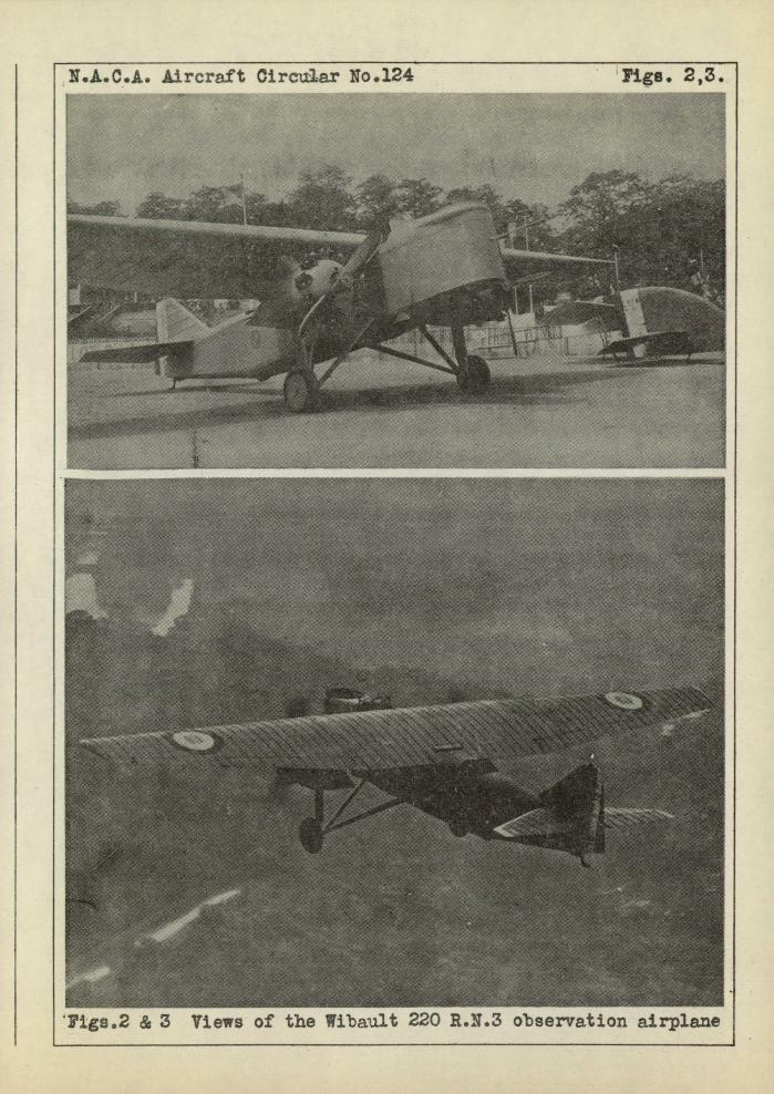
This three-place monoplane has a wing of canti1eve type.
It is all-metal, including the covering of the wing and fuselage
(Figs. 1, 2 and 3).
The exterior form of the wing was determined by finding a
family of profiles capable of giving it a simple geometrical
shape and the best aerodynamic characteristics, and by adopting
a tapered plan form reducing the structural stresses to a minimum.
The relative thickness of the profiles decreases uniformly from
the fuselage to the wing tips, so that at any point, the dimen-
sions of the structural elements are proportional to the stresses
to be withstood. The wing has two I spars rigidly joined by
strong cross pieces which limit the torsional stresses ad defor-
mations. The cross bracing is reduced as much as possible, the
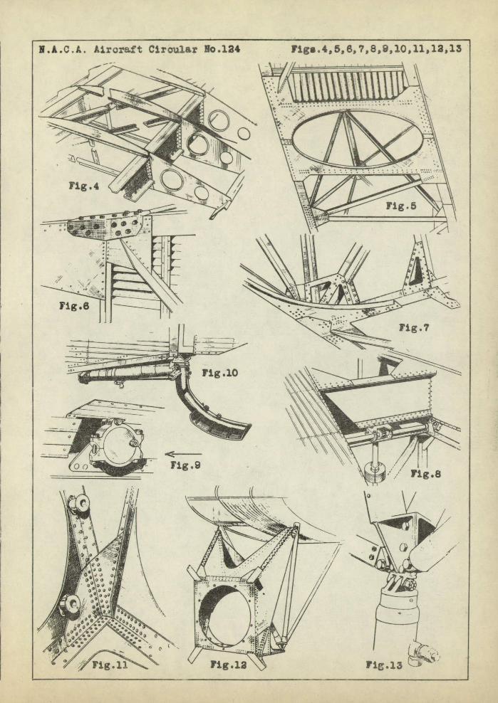
covering helping to absorb the stresses. As shown in Figure 4,
each wing spar consists of two T flanges with a sheet-metal
web. Each rib is composed of four pieces.
The fuselage has a rectangular structure composed of duralu-
mm shapes. 1t has a dorsal and a ventral cowling, the former
being removable in two parts, so as to enable the rapid inspec-
tion of the controls.
The front part carries the cockpits for the navigator and. the
*From L!Aeronautique, July, 1930, pp. 244-246.
N.A.C.A. Aircraft Circular No.. 124
2
pilot, as also for the machine gunner. The rear part carries the
machine gun for firing under the, fuselage and tail. The front
part of the fuselage also contains the 735-liter (194 gal..) fuel
tank.
The fuselage structure is illustrated by Figures 5-7. Figure
5 is a view of the under side of the fuselage showing the oval
opening for the F050 cm photographic camera in the metal plate
connecting the two lower longerons. The central portion, in front
of the opening, is covered with a floor of corrugated sheet metal.
At the rear there is an bpening for firing the machine gun under
the 'fuselage. The bottom of the fuselage has an elliptical cowl .-
ing. An opening permits the dumping of the fuel tank.
Figure 7 shows the openwork gussets permitting the passage
of the controls.
The mechanism for regulating the tabilizer is shown in Fig-
ure 8. By means of a cable, the pilot operates the two-part pul-
ley on the vertical shaft and the motion is converted by an end-
less screw into the rotation of the horizontal shaft visible un-
der the front spar of the stabilizer. The vertical displacements
of the spar are effected 'dy an eccentric attached to the horizon-
tal shaft. Figure 9 is an exterior view of the eccentric, show-
ing also the ?I Tecalemit tl oiler.
The dirigible Messier oleo-pneuinatic tail skid is shown in
Figure 10.
The engines are suspended from the central part of the wing,
one on each side of the fuselage. They are supported by a system
N.A.C.A. Arcraft Circular No. 124 3
of tubes serving also for attaching the shock-absorber struts
of the landing gear. The two 420 hp Gnome-Riione uJupiterU en-
gines are supported by mounts made of duralumin. shapes and plates.
Details of the engine mount are shovrn in Figures 11-13.
Figure 11 shows the inside of one of the corners. It is a simple
structure of metal plates, angles and gussets. The bolts for
securing the engine pass through short cylindrical tubes of dural-
umin. Figure 12 is a general view of the mount and of its three-
point attachment to the wing. Two fittings on the front apex
receive the upper arms of the mount and two tubes. These tubes,
with a third, supported by the rear spar, form a trihedral
frame, to the top of which is attached the single lower plate of
the mount and the Messier elastic strut, the details of which
are shown in Figure 13. On the front of the mount there are four
plates at 45° for receiving the cowling.
The landing gear is of the independent-wheel type and has
long-stroke oleo-pneurnatic brakes and. a very wide track gauge.
The tail surfaces are constructed on the same principles as
the wing and are entirely cantilever. The symmetrical biconvex
profile lifts well at large angles of attack and thus insures
stability at all the regimes of flight.
N.A.CIA. Aircraft Circular No. 124
4
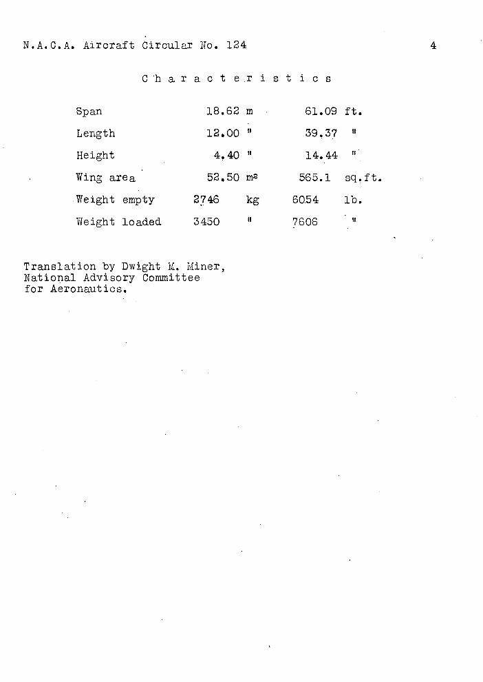
Char act e.r let ice
Span 18.62 m 61.09 ft.
Length 12.00 39.37 °
Height 4,40 " 14.44
Wing area 52.50 m2 565.1 sq.ft.
Weight empty 2746 kg 60,54 lb.
Weight loaded 3450 7606
Translation by Dwight M. Miner, National Advisory Committee for Aeronautics.
N.A.C.A. Aircraft Circular No.124
Fig.1
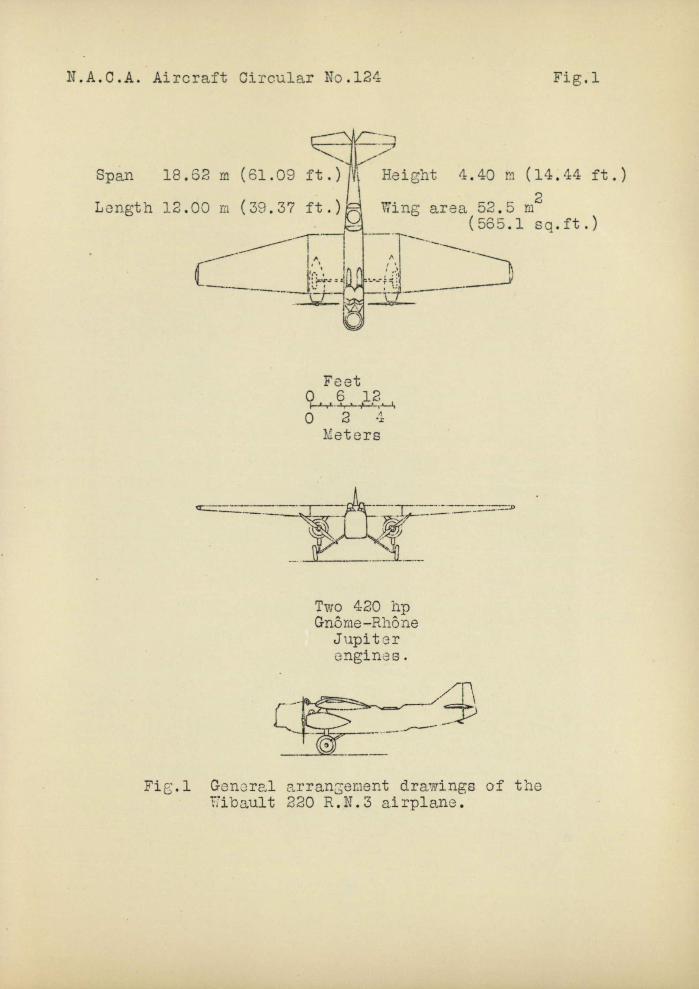
Span
18.S2 rn (61.09 ft.)
Longth 12.00 m (39.37 ft.)
Height 4.40 rn (14.44 ft.)
Wing area 52.5 m2 (565.1 sq.ft.)
Feet o 6 12 r 2 U
Meters
Two 420 hp Gnô me -Rho ne
Jupiter enginas.
Fi.1 General arrangement drawings of the ibau1t 220 R.N.3 airplane.
N.A.C.A. Aircraft Circular No.124 Pigs. 2,3.
-


![Cover + layoutcbseacademic.nic.in/web_material/Circulars/2016/47...2 lkjka'k tSfod [ksrh dk fopkj] i;kZoj.k izsfjr yksxksa }kjk i`Foh vkSj euq"; ds chp lcls vPNk laHko laca/ cukus](https://static.fdocuments.net/doc/165x107/5fad2f81b01e14009a766d9a/cover-2-lkjkak-tsfod-ksrh-dk-fopkj-ikzojk-izsfjr-yksxksa-kjk-ifoh-vksj.jpg)