Airbus 70 A300 A310 Engine Powerplant - GE CF6-80A3
206
A310-200 80A3 ATA 70-80 Page 1 MTT For Training Purposes Only A310-200 CF6-80A3
-
Upload
elijah-paul-merto -
Category
Documents
-
view
441 -
download
113
description
Airbus A300/A310 ATA 70-80 Training Manual. Contains the operation of the GE CF6-80A3 Powerplant.
Transcript of Airbus 70 A300 A310 Engine Powerplant - GE CF6-80A3

A310-200
80A3 ATA 70-80Page 1
MTT
For Training Purposes Only
A310-200
CF6-80A3

A310-200
80A3 ATA 70-80Page 2
MTT
For Training Purposes Only
THIS PAGE INTENTIONALLY LEFT BLANK

A310-200
80A3 ATA 70-80Page 3
MTT
For Training Purposes Only
ATA 70 - 72
GENERAL

A310-200
80A3 ATA 70-80Page 4
MTT
For Training Purposes Only
Access and pressure relief door-vents.
The following access doors are provided in the fancowl :
Left fan cowl
Starter valve normal override
Hydraulic filter
Pressure relief door
Right fan cowl
IDG
Engine oil tank
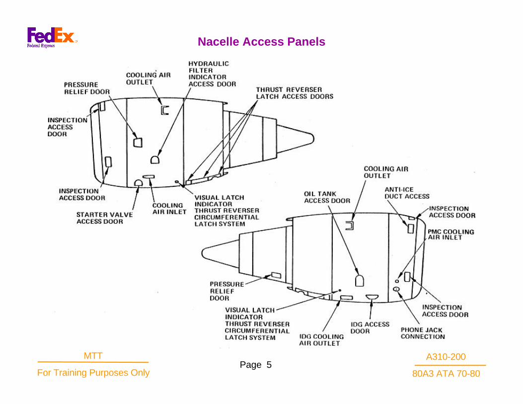
In addition, a compartment cooling air inlet providesair directly toward the accessory gearbox near thehydraulic pumps.A fan reverser latch visual indicatoris located in both fan cowls.
Nacelle Access Panels
A310-200
80A3 ATA 70-80Page 5
MTT
For Training Purposes Only
Nacelle Access Panels

A310-200
80A3 ATA 70-80Page 6
MTT
For Training Purposes Only
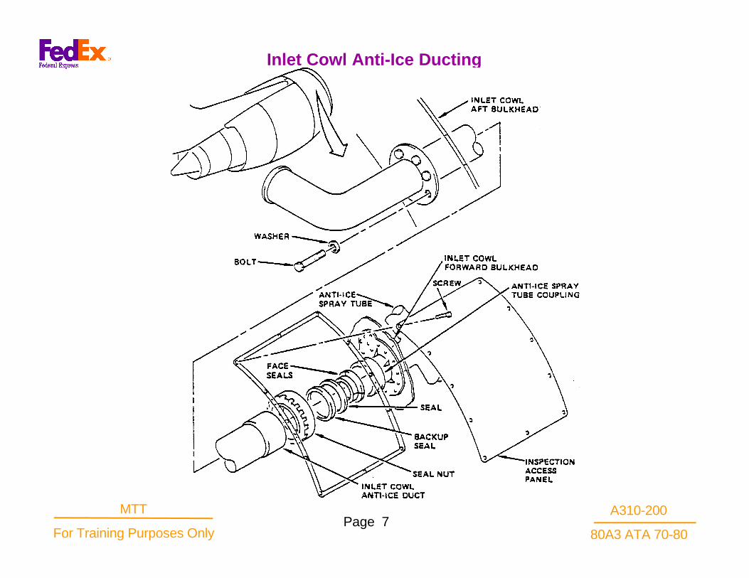
The inlet cowl anti-Ice ducting is routed from the anti-Ice shutoff and regulating valve through the inlet cowlaft bulkhead, and between the inner and outer barrelsof the cowl structure to the duct located in the inlet lipassembly. A slip joint is provided immediately aft of theinlet lip bulkhead to allow for duct thermalexpansion.The anti-Ice duct terminates with a spraytube discharge.Hot l0th stage air flows into the inlet lipcavity through discharge holes in the spray tube. Theair enters a flow passage formed by the inlet skin andbulkhead, and exits through holes located around theperiphery of the inner barrel. The air exhausted intothe inlet cowl aft of the inlet lip bulkhead flows betweenthe outer and inner barrels, and is dischargedoverboard through an exit duct located on the bottomcenter-line of the inlet cowl.
Inlet Cowl Anti-Ice Ducting
A310-200
80A3 ATA 70-80Page 7
MTT
For Training Purposes Only
Inlet Cowl Anti-Ice Ducting

A310-200
80A3 ATA 70-80Page 8
MTT
For Training Purposes Only
The inlet cowl anti-Ice shutoff and regulating valveis a solenoid-controlled,spring loaded open,Pneumatically-operated valve. Wrench flats on theexterior of the valve permit locking the valve ineither open or closed position. Force required toposition the valve is less than 75 inch-pounds. Amechanical position indicator located on the valvebody gives visual indication of the valve position.The valve is permanently marked with arrows onthe valve body to indicate airflow direction and thecorrect installation position. The valve is springloaded open and is closed by applying solenoidvoltage and inlet pressure. Inlet cowl anti-Iceshutoff and regulating valve position is controlledby energizing or de-energizing the valve solenoidby means of a switch in the flight compartment.When the solenoid is de-energized, the valveopens and senses downstream pressure in theanti-Ice ducting and regulates the pressurebetween 123 and 138 psi.
Inlet Cowl Anti-Ice Valve

A310-200
80A3 ATA 70-80Page 9
MTT
For Training Purposes Only
Inlet Cowl Anti-Ice Valve

A310-200
80A3 ATA 70-80Page 10
MTT
For Training Purposes Only
Anti-Ice Pressure Switch
The anti-Ice pressure switch is a single-pole sealedunit installed in the anti-Ice duct sense line. Theswitch actuates at an increasing pressure of 85 psimaximum and a decreasing pressure of 70 psiminimum. When the control switch for the cowl anti-Ice is placed in the "ON" position, the shutoff andregulating valve opens, allowing pressure to build upin the anti-icing ducting. This pressure build upactuates the anti-Ice pressure switch and causes therespective engine anti-Ice system "ON” light toilluminate in the flight compartment.
Anti-Ice Visual Overpressure Indicator
The anti-Ice visual overpressure indicator is a pop-up type pressure sensor connected to thedownstream side of the anti-Ice shutoff andregulating valve. The visual indicator is a red buttonthat pops out if the duct pressure exceeds 190 +/-10 psi . After having been tripped. the button willstay out under all conditions until it is manually reset.The unit may be easily reset with finger pressurewhen no inlet pressure exists.
Inlet Cowl Anti-Ice Overpressure Indicator

A310-200
80A3 ATA 70-80Page 11
MTT
For Training Purposes Only
Inlet Cowl Anti-Ice Overpressure Indicator

A310-200
80A3 ATA 70-80Page 12
MTT
For Training Purposes Only
Two hold-open rods are attached at one end to thelower inside surface of each fan cowl door.The free ends of the rods are stowed in clips on theinside of the door when not in use. The hold-open rodsengage detents on the fan case, and may be extendedto hold the door in either the 40 degree open positionor the 55 degree open position.
Hardpoints and nutplates have been incorporated atthree places in the upper part of the exterior skin ofeach fan cowl door for installation of sling-attach pads.The pads are installed as needed to aid removal,installation, or handling of the fan cowl door. Fillerplugs are installed in the nutplates when the pads arenot in use.
Fan Cowl Door

A310-200
80A3 ATA 70-80Page 13
MTT
For Training Purposes Only
Fan Cowl Door
A310-200
80A3 ATA 70-80Page 14
MTT
For Training Purposes Only
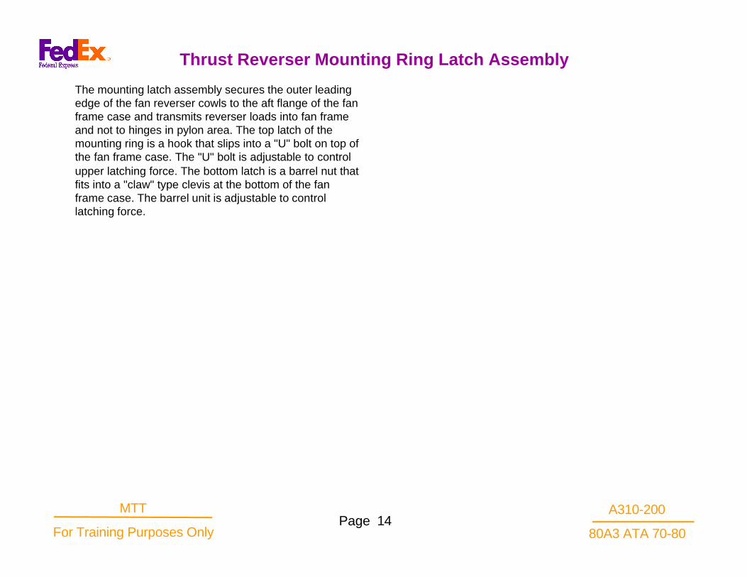
The mounting latch assembly secures the outer leadingedge of the fan reverser cowls to the aft flange of the fanframe case and transmits reverser loads into fan frameand not to hinges in pylon area. The top latch of themounting ring is a hook that slips into a "U" bolt on top ofthe fan frame case. The "U" bolt is adjustable to controlupper latching force. The bottom latch is a barrel nut thatfits into a "claw" type clevis at the bottom of the fanframe case. The barrel unit is adjustable to controllatching force.
Thrust Reverser Mounting Ring Latch Assembly

A310-200
80A3 ATA 70-80Page 15
MTT
For Training Purposes Only
Thrust Reverser Mounting Ring Latch Assembly

A310-200
80A3 ATA 70-80Page 16
MTT
For Training Purposes Only
Throttle Control Mechanical Part
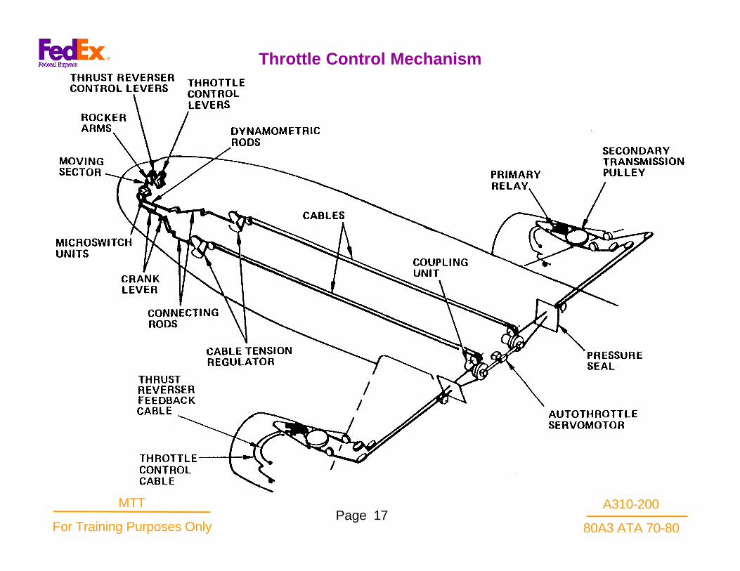
Forward displacement of the throttle control lever resultsin displacement of the dynamometric rod and rotation ofthe bellcrank. Rotation of the bellcrank transmits themovement to a linkage (rods, bellcranks), which in turnrotate a quadrant on which is wound the control cable.After the quadrant, the cable is routed in the cargocompartment, up to the wing root.The autothrottlecoupling unit has the function of a bellcrank and directsthe cable towards the leading edge, at pylon-to-wingattach fitting level, where the secondary relay islocated.The secondary relay consists of a pulley drivenby the cable and is fitted with a pin to which a control rodis attached.This rod sets into movement the primarytransmission crank lever which is connected to aCABLECRAFT flexible push-pull control routed on thefan case periphery. By means of a rod system, the cabledisplaces the power lever located on the MEC.
Throttle Control Mechanism
A310-200
80A3 ATA 70-80Page 17
MTT
For Training Purposes Only
Throttle Control Mechanism

A310-200
80A3 ATA 70-80Page 18
MTT
For Training Purposes Only
Electrical System - LH Side

A310-200
80A3 ATA 70-80Page 19
MTT
For Training Purposes Only
Electrical System - RH Side

A310-200
80A3 ATA 70-80Page 20
MTT
For Training Purposes Only
Forward Pylon Electrical Connector Panel

A310-200
80A3 ATA 70-80Page 21
MTT
For Training Purposes Only
Aft Pylon Electrical Connector Panel
A310-200
80A3 ATA 70-80Page 22
MTT
For Training Purposes Only
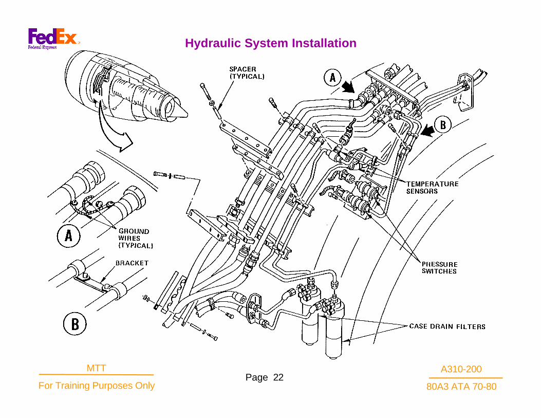
Hydraulic System Installation
A310-200
80A3 ATA 70-80Page 23
MTT
For Training Purposes Only
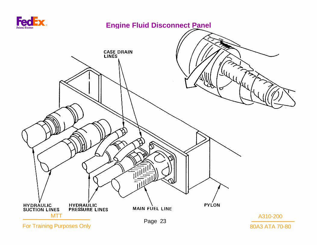
Engine Fluid Disconnect Panel
A310-200
80A3 ATA 70-80Page 24
MTT
For Training Purposes Only
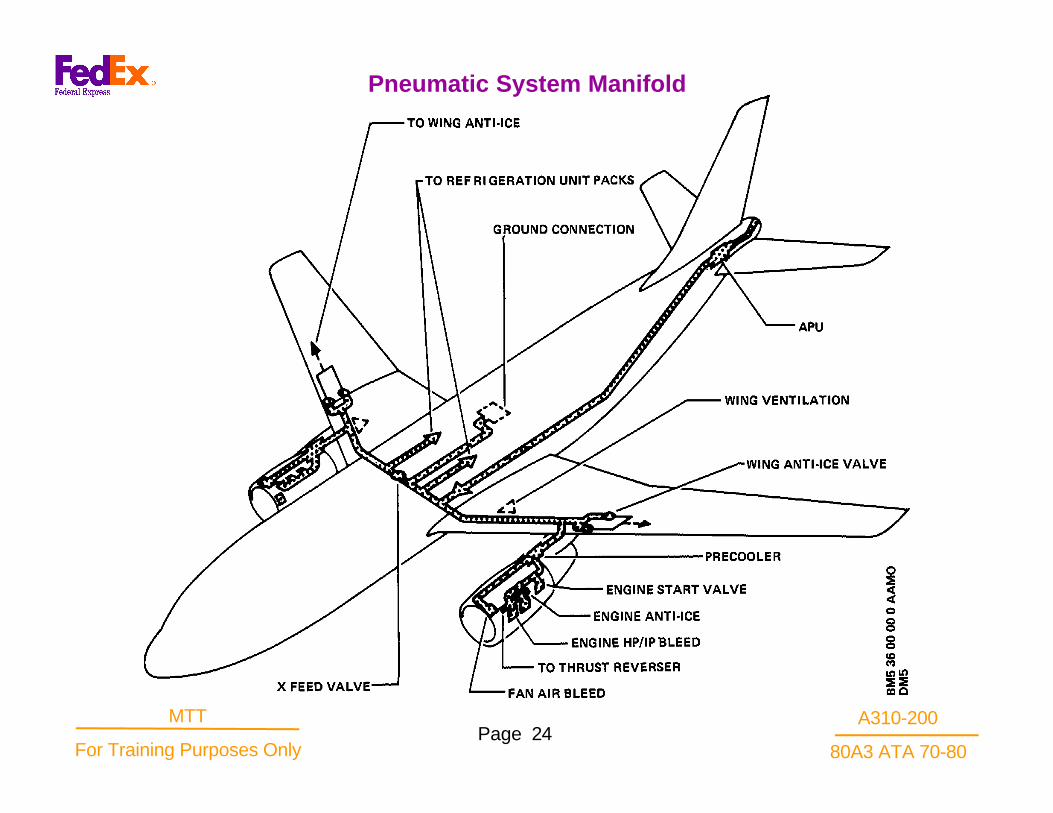
Pneumatic System Manifold

A310-200
80A3 ATA 70-80Page 25
MTT
For Training Purposes Only
Pneumatic System Schematic

A310-200
80A3 ATA 70-80Page 26
MTT
For Training Purposes Only
Pneumatic System Components

A310-200
80A3 ATA 70-80Page 27
MTT
For Training Purposes Only
Pneumatic System BITE Test

A310-200
80A3 ATA 70-80Page 28
MTT
For Training Purposes Only
Engine Drain System

A310-200
80A3 ATA 70-80Page 29
MTT
For Training Purposes Only
Engine Drain Module and Mast
A310-200
80A3 ATA 70-80Page 30
MTT
For Training Purposes Only
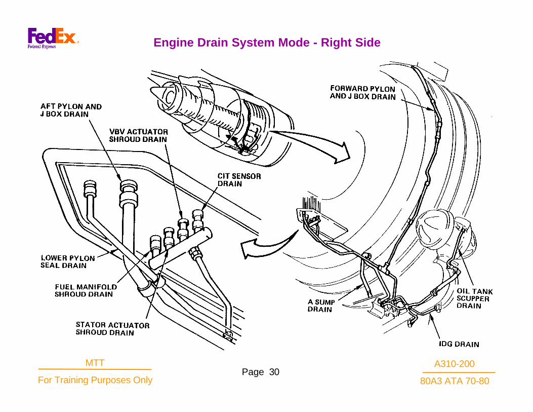
Engine Drain System Mode - Right Side

A310-200
80A3 ATA 70-80Page 31
MTT
For Training Purposes Only
Engine Drain System Diagram

A310-200
80A3 ATA 70-80Page 32
MTT
For Training Purposes Only
The CF6-80 engine is a development of the CF6-50engine. The engines are in approximately the same thrustclass. The differences are in the design changes due to thedesire to reduce length (cowl drag), reduce engine weight,increase efficiency, improve strength, and reducemaintenance costs.
The aircraft application determines which CF6-80 model isused. The Boeing B767 has installed the CF6-80A/A2engine, while the Airbus Industrie A310 has the theCF6.80AI/A3 installed. The differences are in~e location ofthe accessory gearbox. The CF6-80A1 A2 has a coreengine mounted gearbox which makes possible a smallinlet lip which is more efficient aerodynamically. TheC80A1/A3 continues to use the fan stator case mountedgearbox which provides better maintenance andaccessibility features.
Other CF6-80 models are~ identified which provide thrustgrowth. The CF6-80C2 enters the 59,000# thrust class,which\has a larger fan diameter and additional stages inthe low pressure compressor and low pressure turbine. Thelatest model is the CF6-80E 1, very similar to the CF6-80C2 but with even higher additional thrust capability.
Engine Characteristics

A310-200
80A3 ATA 70-80Page 33
MTT
For Training Purposes Only
Engine Characteristics

A310-200
80A3 ATA 70-80Page 34
MTT
For Training Purposes Only
The single most important component of the enginesystems is the Main Engine Control (MEC) whichregulates fuel flow to the combustor and controls thecompressor variable geometry. The other componentsof the power management system work through orsupport the MEC functions. Engine thrust is controlledfrom the cockpit by two systems. The fuel shutoffsystem is a two condition system on, off. Both aircrafttypes provide a lighted electrical switch for eachengine on the center pedestal below the throttle levers.The electrical circuit energizes a motor which drivesthe MEC fuel shutoff le full open or full closed, thusproviding or blocking fuel flow discharge from the MECThe MEC fuel shutoff lever is closed at 0 °-5 ° and fullopen at 40 ° -45° of travel.
The throttle system is used to control speeds aboveidle, and forward or reverse mode of the fan reverser.From the throttle levers for each engine in the cockpitcenter pedestal, there is a system of switches,interlocks, pulley drums, flexible cables and pushrodsto the MEC power levers on the engines. There is aclose angular relationship between the mechanicalmovement of the cockpit throttle levers and the MECpower levers. In addition there is an electrical analog
system of throttle position sensed by the engine mountedPower Management Control unit (PMC) through aresolver installed to the throttle mechanism in thecockpit. The thrust reverse lever , pivoted on the throttle,controls the thrust reverser mode and engine speedcommand the thrust reverse mode.
Power Management Philosophy

A310-200
80A3 ATA 70-80Page 35
MTT
For Training Purposes Only
Power Management Philosophy

A310-200
80A3 ATA 70-80Page 36
MTT
For Training Purposes Only
The CF6-80 MEC uses a corrected N2 speed governingsystem, whereas the previous MEC's were physical N2speed governing controls. Corrected N2 speed isdetermined by a calculation that adjusts existing ambientconditions to standard day base. The calculation used inthe MEC factors in the thrust desired (Power LeverAngle, PLA) and modifies that demand by factors ofambient pressure (Poc) and inlet air temperature (T2) toproduce a speed required for the core rotor (governor) tomove the required amount of air that provides the thrust.
A given mass flow of air thru the engine should producethe same thrust day after day, component deteriorationbeing eliminated. All factors that affect air mass flow arenot included in the calculation, for example humidity andcondensation are omitted, so the results are not perfect,but close. It provides a significant improvement in therelationship of throttle position versus thrust.
N2 Speed Governing

A310-200
80A3 ATA 70-80Page 37
MTT
For Training Purposes Only
N2 Speed Governing

A310-200
80A3 ATA 70-80Page 38
MTT
For Training Purposes Only
The Power Management Control (PMC) is designed tosense throttle position and display on the N1 indicatorthe predicted N1 resulting from that N2 speed, givencorrect G2, P ambient, and Mach number forcalculations. It regulates a direct current power supplyto control a MEC speed trim mechanism that adjustsN2 speed as required to keep N1 on the target valuethe PMC is set for. Aircraft sensors, computers andcockpit displays are integrated with the PMC toachieve this capability.
The PMC schedule is developed as an offshoot of theMEC power lever schedule. The nominal forward MECschedule (PMC-OFF) shows the engine will develop T.0. N1 rpm at a PLA of 1180 (point B). However, if thePMC is ON, the PMC will have down trimmed the MECso much that the throttle will have to be advanced untilthe MEC PLA is at 1270 (point A) before the N1 rpm isat T.O. speed. Notice the PMC schedule is lower than,or downward, from the MEC schedule. The range ofauthority of the PMC speed trim is the space betweenthe two lines, hence the PMC is considered to haveonly down trim authority. The reverse mode MECschedule is below the PMC schedule. Because of themechanism in the MEC, the PMC speed trim cannotexceed the MEC schedule; therefore the PMC is"blocked out" of influence in thrust reverse operation.
PMC Interface

A310-200
80A3 ATA 70-80Page 39
MTT
For Training Purposes Only
PLA vs. MEC Schedule

A310-200
80A3 ATA 70-80Page 40
MTT
For Training Purposes Only
The operation of the engine is managed by the operatorto avoid exceeding the limits established by the terms ofthe sale and the warranties and guarantees provided bythe manufacturer. The thrust output of the engine is oneof the terms identified. Included figure shows a typicalrequirement for N1 in order to develop a specified levelof thrust. Notice the effect of ambient temperature on theN1 speed required. At "A" {colder) less N1 speedproduces the same level of thrust as at B {warmer). Thisis true up to the hot day condition C, which is atemperature identified in the sale terms. Above the hotday temperature the engine becomes EGT {Exhaust GasTemperature) limited in operation rather than a "flatrated" thrust engine. It is termed a "flat rated" enginebecause of the visual characteristic of the thrust curvebelow the hot day temperature. Above the hot daycondition, the thrust obtained from the engine decreasessharply because the core section of the engine, being atits EGT operating limit, cannot operate at higher speedsto drive the fan to higher speeds. The data provided insuch figures is available in the flight manuals andprogrammed into the thrust control computers of theaircraft.
N1 speed has been selected as the thrust settingparameter. It is not the only parameter that can providethis function. Engine pressure ratio (EPR) is acceptable,and N2, fuel flow and EGT combined have some value.
The arguments for N1 include:
1). Simple, reliable, maintainable indicatingsystem.
2). Deterioration in modules other than the fan resultin increases in fuel flow and EGT producing increasesin the core thrust component of total thrust.
3). The fan module is easy to observe visually toassure no deterioration in performance capability.
4). With a PMC system (Power Management Control)there is a consistent relationship between throttleposition and thrust.
Thrust Output

A310-200
80A3 ATA 70-80Page 41
MTT
For Training Purposes Only
N1 Speed For Rated Thrust

A310-200
80A3 ATA 70-80Page 42
MTT
For Training Purposes Only
TheT1.2 sensor provides an electrical signalproportional to the fan inlet air total temperature. Theelectrical signal is required by the power managementcontrol as a parameter in its computations. The PMCuses the T1.2 signal to compare with aircraft furnishedtemperature. A detected failure of the aircrafttemperature signals causes the PMC to rely on the T1.2signal for computation of required N1.
The sensor is installed in the fan stator case forward ofthe fan containment at 4:30 o'clock (all). The sensoremploys a platinum resistance element wound on aceramic core energized from the power managementcontrol. A constant current ( 12 1/2 ma), 10v DCmaximum power circuit supplied by the PMC isinfluenced by the temperature of the inlet air on theplatinum resistance element. The variation of resistancechanges the circuit voltage directly with temperature,typically 1 1/2 -3 1/2 VDC.
Engine Sensors - T1.2 Sensor

A310-200
80A3 ATA 70-80Page 43
MTT
For Training Purposes Only
Engine Sensors - T1.2 Sensor

A310-200
80A3 ATA 70-80Page 44
MTT
For Training Purposes Only
The probe is protected by being placed in a trailingposition of a hollow vane and a second vane in thewake of the first. The device is approximately 2" W X 11/2" L X 5" H and weights about 1 pound. There is afour hole rectangular mounting plate for bolting to theforward fan case thru isolation pads. A five pin electricalconnector is used providing a redundant circuitcapability.
Electrical T1.2 Sensor

A310-200
80A3 ATA 70-80Page 45
MTT
For Training Purposes Only
Electrical T1.2 Sensor

A310-200
80A3 ATA 70-80Page 46
MTT
For Training Purposes Only
The sensor elements are two thin wall INCO 718 fingertubes pressurized with helium. A rectangular insulatedcooling plenum surrounds and protects the sensorelements. There are tubular extensions for connection tothe cooling air tubes. The inline valve body and fuel tubeconnections are outside the mounting flange. The sensoris approximately 4 1/2" L x 3 1/2" W x 4 " H, weighingabout 2 1/2 pounds. The mounting flange has bolt holesasymmetrically located on the rectangular plate. Thereare two fuel tube spherical seat adapter ports on onesurface labeled P7 and Pb. The fuel tubes are notshrouded. The MEC servo pressure, Pc, is used asmuscle to rotationally position a 3-D cam proportional tothe P7 -Pb pressure developed in the T2 sensor. Theaxial position of the 3-D cam is the result of an altitudesensor signal. The 3-D cam output and the power leverposition cam combine to produce a corrected N2 speedrequirement on the MEC fuel metering valve controlgovernor. The CF6-80A3 sensor is installed in a similarduct on the fan stator case at 4:00 o'clock. The sensor isconstructed so that only the two tubular probes extendinto the duct.
T2 Sensor

A310-200
80A3 ATA 70-80Page 47
MTT
For Training Purposes Only
T2 Hydromechanical Sensor

A310-200
80A3 ATA 70-80Page 48
MTT
For Training Purposes Only
This device provides a fuel pressure signal proportionalto the temperature of the high pressure compressorinlet air (CIT or T25). The hydromechanical fuel controlunit uses this pressure to compute correctedacceleration fuel flow and compressor airflow controlsystem requirements.
The sensor is installed in the fan frame at 4:30 o'clock(ALF) and attached by its flange to the frame.
Construction FeaturesThe portion of the sensor in the airstream is a coiledtube pressurized with helium, The sensor element isprotected by an outer sheet metal covering and bymetal rings welded to the outer covering to protect thecoiled tube fore and aft from ice impact and sheddingvibration frequencies.
A rain shield is installed at the air flow inlet side of thesensing element. It is a conical section of sheet metal. Itprevents direct water impingement onto the sensingbulb and the subsequent temperature error induced byevaporative cooling.
Within the engine compartment are the fuel signalpressure servo supply (P6), return (Pb) shrouded "B"nut connections and the inline regulator valve body.
The sensor is approximately 41/2" L x 4' W x 5" H.It provides a square mounting flange. Its shapeassures one way installation to provide properairflow through the coiled tube. The two fuel lineconnections are by shrouded fuel tube couplings.The ports provide P6 and Pb couplings for linesgoing to the MEC P6 and Pb ports.
The inline regulator valve (Flapper) is controlledby the effects of air temperature on a confinedvolume of gas. An aneroid (Motor Bellows)connected to the sensing coil reacts against a coilspring and a vacuum chamber (ReferenceBellows) to position a variable orifice. Cold airreduces the aneroid pressure opening the variableorifice permitting the fuel supply pressure (P6) todrop proportionately. The force balance isestablished at the flapper valve. Very little actualvalve area changes are necessary to develop thepressure changes necessary.
Compressor Inlet Temperature (CIT) Sensor

A310-200
80A3 ATA 70-80Page 49
MTT
For Training Purposes Only
CIT Sensor

A310-200
80A3 ATA 70-80Page 50
MTT
For Training Purposes Only
The N1 sensor serves three functions: N1 speedindication to cockpit indicator, speed input to PowerManagement Control (PMC), a 1/rev signal for fan trimbalance. The N1 speed sensor produces two signals.One goes to the N1 indicator for actual speed. Theother is compared with the N1 command signal in thePMC. If a difference is noted, a torque motor drivesignal will adjust the MEC down trim mechanismchanging N2 speed, to make the actual speed agreewith the command N1 . An N2 speed change will have adirect effect on the N1 speed.
The sensor is installed into the "A" sump pressuresleeve through strut #3. It extends to a point close to a38 tooth rotor cage at the #2 bearing inner raceassembly. The magnetic tip is protected from sump oilby a titanium receiver in the fan frame pressure sleeve.The assembly provides a Viton bushing for supportmidway along the lead, a spring loaded flangedmounting adapter, and an electrical connector. Thespring loaded mounting assembly provides from 25-80pounds axial force to keep the magnetic tip seated intoits titanium receiver.
The sensor tip contains a permanent wafer magnet andtwo coils in tandem. The coils are part of separatecircuits, one dedicated to the PMC and one for cockpitindication. The chromel leads are insulated bymagnesium oxide swaged within the stainless steeltubular housing. The N1 analog signal to the N1indicator is routed through the PMC, but remains
electrically isolated. The other circuit provides afan speed input to the PMC. This signal isprocessed into digital words for use in the PMCand transmission over the data bus for the N1indicator digital display.
The device is self energized. It produces anelectro-magnetic pulse whenever the magneticfield at the tip is disturbed by the passing teeth ofthe rotor cage on the fan shaft forward of theNo.2 bearing inner race. The rotor cage has oneof the 38 teeth modified to pass closer to thesensor producing a stronger signal. It enables avibration analyzer to detect a I/rev signal used inrotor trim balance.
Electrical N1 Fan Speed Sensor

A310-200
80A3 ATA 70-80Page 51
MTT
For Training Purposes Only
Electrical N1 Fan Speed Sensor

A310-200
80A3 ATA 70-80Page 52
MTT
For Training Purposes Only
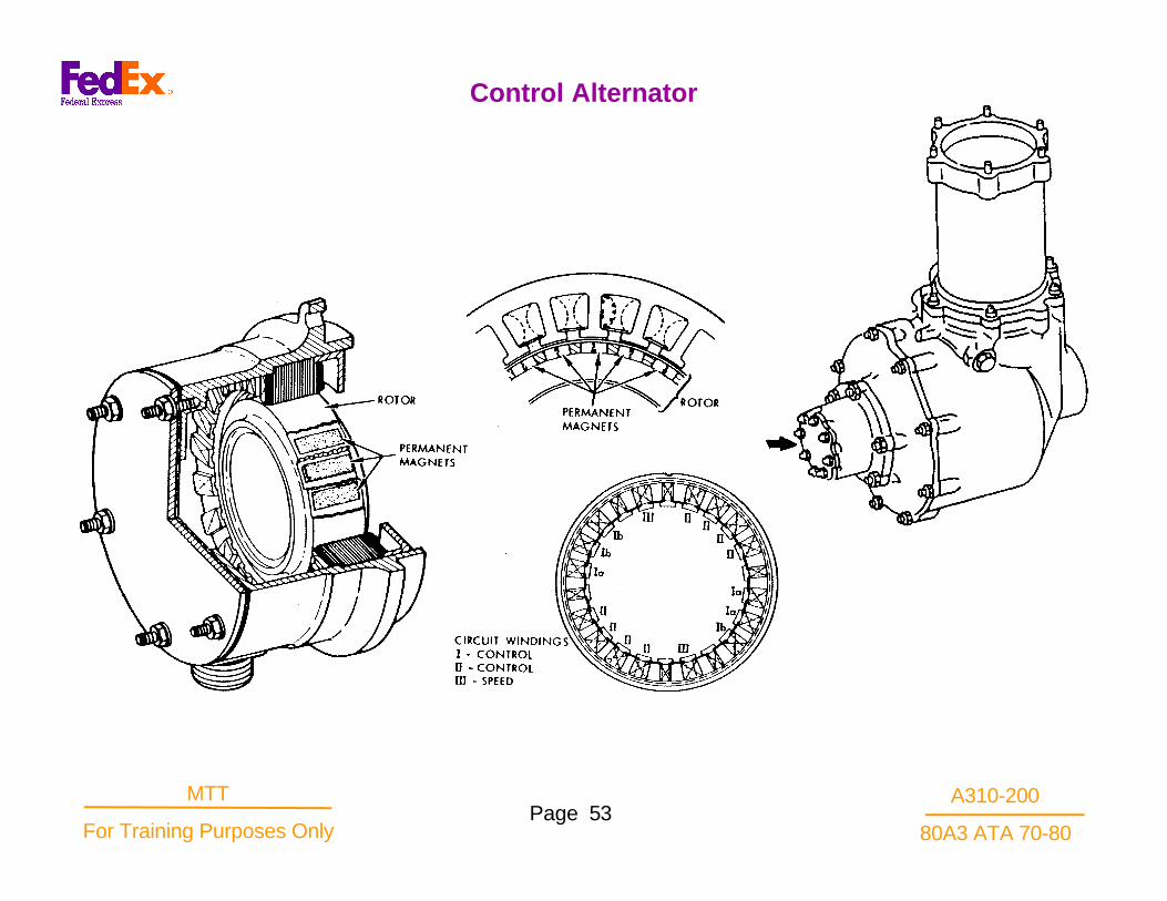
The alternator is installed on the transfer gearbox padopposite the horizontal drive shaft. The rotor will turn at9397 RPM at 100% core speed.
The stator provides twenty two poles. The pole windingsare separately part of the three circuits: speedindicating, and two power circuits for the PMC. One tenpin connector gives access for the service cable. Thestators are interchangeable. An access cover plate onthe aft surface must be removed to install a core enginemotoring device for borescope inspection. The motoringdevice will bolt to the stator housing and the drive shaftwill fit into the TGB spacer square drive. The rotor isattached to the TGB horizontal drive shaft and keyed.The rotor contains twenty two permanent magnets withthe N and 8 poles alternating. The spacing is the sameas the stator poles. The rotors are interchangeable.The power circuit produces 210 volts max. open circuitvoltage, 3.5 amps max short circuit current and thefrequency ranges from 775 Hz at 45% N2 to 1895 Hzat 110% N2. The speed signal produces 50 volts max.open circuit voltage, 5.4 amp. max. short circuitamperage at frequency ranges between 51.7 Hz at 3%N2 to 1895 Hz at 110% N2.
Control Alternator
A310-200
80A3 ATA 70-80Page 53
MTT
For Training Purposes Only
Control Alternator

A310-200
80A3 ATA 70-80Page 54
MTT
For Training Purposes Only
The EGT indicating subsystem provides a cockpit displayof the engine primary airflow temperature at enginestation 4.9, inlet to the LPT. The indicating system gagespermit the operator to monitor the condition of the enginefor that parameter, and initiate corrective action, ifnecessary. There are eight chromel-alumel thermocoupleprobes installed into bosses of the LPT forward case.This location is station 4.9 and is just ahead of LPT stage1 nozzle and aft of the HPT stage 2 rotor .
There are two configurations of EGT harnesses andprobes.
The rigid type thermocouple harness contains four pairedprobe sections, each probe containing twothermocouples, each section providing a 4 pin connector.There is a left hand and right hand averaging harnessinterconnecting sections 1 thru 4 to the junction box.There is a third connector on the junction box for theforward lead connection to the aircraft interface. Eachprobe of a harness pair contains two chromel-alumeljunctions making a total of 16 junctions. The junctionsare encased in a swaged stainless housing usingMagnesium Oxide (MgO) as the insulation. Each probehas two immersion depths within a protective sleeve. Thesleeve is drilled so there is a positive circulation ofgasses around the probe.
The flexible type thermocouple harness contains anupper and lower averaging harness, with each harnessconnecting to eight individual thermocouple probes.Each probe contains two chromel-alumel junctionsmaking a total of 16 junctions. The upper and lowerharnesses individually connect to a singlejunction/shunt box mounted on the left side of theengine. From the junction/shunt box is a single aircraftinterface connector. Through the shunt portion of thejunction box, the output signal is reduced by 35 deg.Cto the aircraft indicator.
Exhaust Gas Temperature (EGT) Probes

A310-200
80A3 ATA 70-80Page 55
MTT
For Training Purposes Only
EGT Sensing System

A310-200
80A3 ATA 70-80Page 56
MTT
For Training Purposes Only
The thermocouple probes for either application areidentical in operation. Hot gasses circulate about theprobes heating the junction of dissimilar metals(chromel and alumel) causing a voltage potential todevelop. A circuit is formed in the indicating systemwhen the other ends of the leads are joined ( the coldjunction) at the indicator. The indicator moves up scalewith increased gas temperatures, a function of theincreased potential as gas temperatures increase.Malfunctions of the system affect the indicating abilityas well as the averaging ability. Short circuits and openor high resistance connections prevent indications.Sometimes new junctions are formed by shorts whichalter the balance of the circuits and influence theaverage temperature indication either higher or lowerdepending on the location of the new junction.
Thermocouple Probe

A310-200
80A3 ATA 70-80Page 57
MTT
For Training Purposes Only
Thermocouple Probe

A310-200
80A3 ATA 70-80Page 58
MTT
For Training Purposes Only
The fuel pump contains an integral centrifugal boostelement and a high pressure positive displacement gearelement. An external fuel/oil heat exchanger is locatedbetween the high pressure element and the fuel filter toprovide fuel heating and oil cooling functionscontinuously. The fuel filter for the engine providesfiltration protection for the MEC and the fuel servosystem including the stator and bleed valve actuators,CIT sensor, hydromechanical T2 sensor, fuel flow meterand IDGS oil/fuel heat exchanger (both customerfurnished), and fuel nozzles.
A filter relief valve permits continuous flow to the MEC inthe case of clogging. The relief valve cracks open whenthe pressure drop in the filter reaches 35 +/- 5 psid. Thisrelief valve is fully open when pressure drops to 45 psid.
A servo fuel heater provides preheat to the servo fuel ofthe MEC to prevent the formation of ice within the MECsensor servo valves. It is not required on the -80Al/A3engine.
A pressurizing valve in the MEC maintains minimumsystem pressure.
The 30 fuel nozzles are grouped in ten clusters ofthree each. They are of two types: twenty- onehave primary and secondary while nine havesecondary flow only. Check valves in the fuelnozzles prevent back flow on shutdown.
Type of Fuel
The engine will operate satisfactorily when usingfuels conforming to, alternately, or in anycombination: MIL-T-5624K Grade JP-4 or JP-5;MIL-T-83133 Grady JP-8; ASTM D 1655, JET A,A-l and B, and approved fuel conforming to theGeneral Electric Specification D50TF2.
Fuel Delivery System

A310-200
80A3 ATA 70-80Page 59
MTT
For Training Purposes Only
Fuel System Schematic

A310-200
80A3 ATA 70-80Page 60
MTT
For Training Purposes Only
The pump produces the fuel flow required to producethe thrust level selected by the operator. The pumpreceives fuel from the aircraft supply at relatively lowboost pressures. The pump provides additional boostfrom its internal centrifugal stage to supercharge itshigh pressure pump element to prevent cavitation. The-80A3 pump is like the CF6-50 pump. It is installed onthe 7 o'clock pad on the aft of the fan mounted AGB.Attachment is by a QAD ring to the gearbox. Alignmentpins assure correct positioning.
The pump is driven by the AGB thru a splined shaftturning a centrifugal impeller, a gear pump, and theMEC drive spline. The drive shaft spline is lubricatedby engine oil from a jet in the lube pump delivering oilinto the common gearshaft. There is a groove for an"0" ring just aft of the spline, and a metal bracket sealring completes the drain cavity by making a seal at themounting flange. The drive shaft, as it enters thepump, employs an impregnated babbit type of seal.Therefore, seal failures might allow oil or fuel to drainfrom this AGB drain port. The other parts of the pumpand drive shaft are all fuel lubricated. This fact givenrise to the requirement that any time the engine ismotored there must be a positive fuel pump pressureprovided by the aircraft boost pumps.
Fuel flow thru the pump begins at the fuel inlet portwhere the connection to the fuel supply is made. The
fuel enters directly into the center of the centrifugalelement and is discharged thru the scroll at anincreased pressure. The pressure increasedepends upon the engine speed. Ground Idleprovides approximately 40 psi increase, flight idle50 psi, and takeoff rpm approximately 60 psi. Themaximum pressure increase above aircraft boost isin the region of 80 psi at the extremes of rpm andtemperature. The cockpit indication of FuelPressure is from a tap in the Boost discharge intothe jet eductors. The gage reads both the tankboost pump pressures and the MFP boostpressures .
Main Fuel Pump

A310-200
80A3 ATA 70-80Page 61
MTT
For Training Purposes Only
Fuel Pump, Heat Exchanger and Fuel Filter

A310-200
80A3 ATA 70-80Page 62
MTT
For Training Purposes Only
The centrifugal discharge flow is used to power twoparallel jet eductors to remove and pressurize fuelvapors that may collect in pylon vapor traps, thuspreventing vapor lock in the aircraft fuel lines andproviding takeoff power capability without aircraft boostpump operation. Any combined fuel and vapor re-enterthe centrifugal element at mid stage and is forced tothe inlet of the gear element. The vapor inlet port maybe capped on some models of A310 aircraft.
The high pressure gear element inlet flow is filteredthru the Debris screen. The screen has a 520 micronvalue. It will protect the gear element from largeparticles and chunks generated upstream, but willbypass when clogging creates a 5-10 psi pressuredrop. This cartridge screen should be inspected andcleaned periodically, as there is no bypass indication.
The positive displacement gear pump provides fuelquantity and pressures in excess of requirements at alloperating conditions assuring a bypass flow. Thepressure is limited only by the High Pressure Reliefvalve which opens at 1350 psid., full open by 1600psid. The fuel is dumped to the gear pump inlet torecirculate, limiting the pressure. The MEC establishesthe discharge pressure level by regulating the bypassfuel flow recirculating into the pump.
There are temperature and pressure ports provided forinstrumentation. All ports are identified by cast letters.
Fuel Pump

A310-200
80A3 ATA 70-80Page 63
MTT
For Training Purposes Only
Fuel Pump Schematic

A310-200
80A3 ATA 70-80Page 64
MTT
For Training Purposes Only
The fuel oil heat exchanger provides a single componentto heat the fuel and to cool the scavenge oil by heattransfer. (Except when servo fuel heater is installed).Itcontains tubes and baffles to direct the flow of respectivefluids. Fuel into manifold, through half of tubes to enddome, returning through remaining tubes, and exiting through the manifold. All fuel flows through heatexchanger -no bypass. Scavenge oil flows by or througha pressure relief valve before entering the exchanger.
85 psid cracking, 100 psid full open.
Scavenge oil makes six passes across the fuel tubes before exiting.Fuel pressures are always higher than theoil pressures.
Fuel Oil Heat Exchanger

A310-200
80A3 ATA 70-80Page 65
MTT
For Training Purposes Only
Heat Exchanger

A310-200
80A3 ATA 70-80Page 66
MTT
For Training Purposes Only
The fuel filter provides fuel free of contaminant particleslarge enough to cause Main Engine Controlmalfunction. It is bolted to flanged ports on right side offuel pump (ALF). Differential pressure taps on fuelpump ports provide cockpit signal of impending filterbypass. Fuel filter clogging indicator on at 23 +/- 2 psid,off at 19.5 psid.
Filter Bypass Valve is Belvalve type. Cracks at 38 +/-psid, full open at 45 psid.
Filter element is disposable type 10 micron, may beinstalled either end up.1.) Epoxy impregnated inorganic media
(glass/polyester).2.) Coarse aluminum mesh supports pleated media.
Filter bowl is installed hand tight and safety wired.1.) Drain Plug.2.) Seal rings each end of filter and in filter head to seal
bowl.3.) Undamaged seal ring in filter head is reusable.
Removal features on the filter bowl allows use of a strapwrench, or on some models a screwdriver shank toapply removal torque.
Fuel Filter

A310-200
80A3 ATA 70-80Page 67
MTT
For Training Purposes Only
Fuel Filter

A310-200
80A3 ATA 70-80Page 68
MTT
For Training Purposes Only
The MEC is installed in tandem with the main fuel pumpon the aft 6:30 drive pad of the fan case mountedgearbox. While there are differences in the mountingsystem and the external appearance, the MECfunctions are the same. The MEC is a hydromechanicalcomputer designed to regulate fuel flow under alloperating conditions, regulate Compressor airflow, andprotect the engine from adverse operation. The controlfunctions of the MEC are:
N2 fuel metering
Variable stator control
Variable bleed value control
Electrical interface with the Power Management Control (PMC) for N1 speed control
Electrical interface with aircraft for idle speed control
Electrical interface with aircraft and PMC for N1 speed control protection
Main Engine Control

A310-200
80A3 ATA 70-80Page 69
MTT
For Training Purposes Only
Main Engine Control

A310-200
80A3 ATA 70-80Page 70
MTT
For Training Purposes Only
The input parameters of the MEC are:
a.) Physical core engine speed (N2)
b.) Throttle position (PLA)
c.) PMC torque motor current (TMC)
d.) Compressor inlet temperature (T2.5)
e.) Altitude Sensing (PoC)
f.) VSV feedback
g.) VBV feedback
h.) Idle reset solenoid signal
i.) Fail fixed solenoid signal
j.) Compressor discharge pressure (CDP)
Input Parameters Of The MEC

A310-200
80A3 ATA 70-80Page 71
MTT
For Training Purposes Only
Main Engine Control

A310-200
80A3 ATA 70-80Page 72
MTT
For Training Purposes Only
MEC power lever is positioned manually through theaircraft throttle system. A speed command will beapplied to the isochronous governor controlling fuelflow through the fuel metering valve proportional to thePLA biased by the T2 and PoC three dimensional cam.N2 speed provides a feedback to the governor .
Reverse thrust range is 10.50 to 400 PLA (B767) and18.20-400 (A310) 10,300 rpm to 5500 N2 rpm.
Minimum idle is 400- 570,5,500 N2 rpm. However, theA310 incorporates a modulated idle rather thanminimum and approach idle selected by the idle resetsolenoid. The modulated idle provides necessarycompressor bleed air at minimum fuel burn on descentfrom altitude.
Forward thrust range is 570 to 1300 PLA, 5,500 rpm to10,300 N2 rpm. The above under conditions of T2 =59° and Poc is 14.7 psia.
Throttle Rig position is at 130° PLA, (Maximumforward speed command). A 80 ° PLA rig pin positionis provided for aircraft rigging. A check for full throttlecapability to 130° PLA is desirable following aircraftrigging.
The PMC speed trim adjustment is applied to thegovernor to modify the basic signal derived from thethrottle position.
The slope of the power lever cam schedule and the fan
inlet temperature and ambient pressure bias provideapproximately constant thrust per degree of powerlever angle (in PMC "disable" mode), regardless oftemperature or ambient pressure. The MEC is termeda corrected core speed (N2K) control, rather than aphysical core speed (N2) control as used on previousengines of the CF6 family.
Power Lever

A310-200
80A3 ATA 70-80Page 73
MTT
For Training Purposes Only
N1 Speed Control Schematic

A310-200
80A3 ATA 70-80Page 74
MTT
For Training Purposes Only
Acceleration and deceleration schedules -compressorinlet temperature (T2.5 or CIT), N2 rpm, compressordischarge pressure (Ps 3 or CDP). When the throttle ismoved rapidly, the governor will attempt to position thefuel metering valve full open or full closed. Neithercondition provides acceptable fuel schedulingconsidering the effects on the compressor airflow andthe heat change on the metal of the engine. Ahydromechanical computer generated schedule isprovided which has authority over the governor controlof the metering valve. The schedule, based upon T2.5,N2 and CDP, computes the upper and lower fuel flowsdesirable considering overtemperature, compressorstall line and flameout. It permits the maximum saferate of acceleration and deceleration in response tothrottle movement.
Compressor control schedules -compressor inlettemperature (T2.5 or CIT), N2 rpm, mechanicalfeedback of VSV and VBV position. The airflow controlsystems require accurate positioning to match orbalance the capacities of the individual compressorstages. It has been determined through test that themeasure of the stage to stage airflow is proportional tothe calculated corrected N2 speed, indicated N2 timesa T2.5 factor. A three dimensional cam integratesthese factors to drive the servo systems of the VSV's
and VBV's. The feedback cables cause the servo systempilot valves to null when the prescribed position isachieved. The schedules make possible rapid rates ofcompressor acceleration and deceleration.
Compressor discharge pressure (CDP or Ps3) maximumlimit. It is possible that high pressures within thecompressor case may cause case rupture. The CDP cam,which is part of the acceleration-deceleration computer,has a slope reversal starting at 465 psia. When higherpressures are sensed the slope reversal depresses theacceleration fuel schedule limit. The engine speed andpressure may continue to increase until the required to runfuel flow and the depressed accel limit fuel flow are thesame value.
Schedules

A310-200
80A3 ATA 70-80Page 75
MTT
For Training Purposes Only
N1 Speed Control Schematic

A310-200
80A3 ATA 70-80Page 76
MTT
For Training Purposes Only
Minimum idle (range 58% -78% N2 for A310 groundand flight) -PLA, N2 rpm, ambient pressure (Poc),ambient temperature (T2), electrical 28VDC to idle resetsolenoid. When the throttle is at its minimum or idleposition, approximately 48° 500 PLA, the engine speed(N2) will be governed by the selection of minimum idleor approach idle. This selection is the function of theidle reset solenoid power
On the A310, whenever the weight on wheels switch iscompressed, as on the ground, a switch will energizethe idle reset solenoid to select minimum idle. In flight,when the TCC is in operation, Nacelle anti-Ice is off,and slats are not extended the minimum idle will beselected. This mode provides a variable idle speed as afunction of Poc or altitude.
Approach idle (range A310) -PLA, N2 rpm, Poc, T2,removal of power to the idle reset solenoid. On theA310, whenever there is no weight-on-wheels, and T.C.C. is not in operation or nacelle anti-Ice is on, or ifslats are extended, the engine minimum throttle positionspeed will be approach idle. The circuit to the idle resetsolenoid will be open.
Idle Speeds

A310-200
80A3 ATA 70-80Page 77
MTT
For Training Purposes Only
N1 Speed Control Schematic

A310-200
80A3 ATA 70-80Page 78
MTT
For Training Purposes Only
N2 Minimum range 56.5 + 1% N2. internal speed stopscrew. This is a speed calculated to maintain theIntegrated Drive Generator System above its drop outspeed.
N2 Maximum -range 110.0 + .4% N2. Internal speedstop screw.
N2 overspeed trip -range 111.2- 112.2% N2 rpm. Aredundant system to the fuel metering valve controlsystem. This system increases fuel pump bypass flowas a function of rpm overspeed, thus reducing thecombustion fuel flow to limit gross overspeed.
Corrected N2 speed cutback -N2, T2.5. A function ofthe corrected speed 3-D cam. Protects the enginefrom high EGT in extreme high ambient temperatures,and overthrust in extreme cold temperatures at highengine rpms. This is the prime overspeed protectionsystem. It reduces the acceleration fuel limit schedulewhen excessive corrected N2 speeds are sensed.
Fail fixedFail fixes - electrical 28VDC to the solenoid. It locks atthe existing degree of power trim when the PMCdetects PMC system malfunctions.
Servo pressure regulationMEC inlet fuel supply is used to develop servopressure that position cams, and pilot valves. Apressurizing valve blocks flow to the fuel manifolduntil servo pressure regulation has been achieved.Pcr servo pressure and a spring force equivalent to90 psi keep the valve seated until 240-300 psi abovefuel pump boost pressures is developed. Priority isthus given to hydromechanical computer and servopilot valve functions over the combustion fuel flow.
Min/Max Flows

A310-200
80A3 ATA 70-80Page 79
MTT
For Training Purposes Only
N1 Speed Control Schematic

A310-200
80A3 ATA 70-80Page 80
MTT
For Training Purposes Only
Fuel shutoff control -a cockpit switch to an airframemotor drives the MEC fuel shutoff lever to open orclosed position. It controls the fuel discharge shutoffvalve in the MEC. In the closed position the lever alsocauses the bypass valve to open increasing the fuelrecirculation to unload the pump. The lever moves 450
from closed to open, during which the fuel shutoff valvewithin the MEC is closed below 5 degrees. Positivestops are provided for both limit positions.
MEC Adjustments are VSV feedback (manual), VBVfeedback (manual), minimum idle and approach idlespeeds (manual and remote), and fuel specific gravity.Adjustments to the MEC provide for fuel/air regulationand trimming.
VSV feedback rig -(A310) an adjustable pivot for thereverser arm to which the VSV feedback cable rod endis bolted. The required position is referenced to the VSVrig marks.
VBV feedback rig -an adjustable bracket to which theVBV feedback cable housing is clamped. The requiredposition is referenced to the VBV rig marks.
Specific Gravity -An adjustment made by turning asocket head screw. It determines the differentialpressure across the fuel metering valve to enablecalibration of the flow with different fuels.
Minimum or ground idle adjustment -a socket headscrew. Adjustment raises or lowers minimum idle rpm.
Approach or flight idle adjustment -a socketheadscrew located under the minimum idleadjustment screw which must be removed to adjustapproach idle. A wet port.
Fuel Shutoff

A310-200
80A3 ATA 70-80Page 81
MTT
For Training Purposes Only
Fuel Shutoff Actuator

A310-200
80A3 ATA 70-80Page 82
MTT
For Training Purposes Only
Operation
The hydromechanical MEC will control engine thrustaccurately and reliably even if the PMC is deactivated.Thrust control is through the throttle operated push-pullcable to the MEC power lever. This signal, as appliedthrough the MEC mechanism and hydromechanicalcomputer, becomes a corrected N2 speed command onthe governor controlling the fuel metering valve. Thegovernor adjusts fuel flow to met the command.Corrected N2 speed, core speed corrected to T2 andambient pressure Po, is directly related to N1 and thrust.Corrected N2 speed is a measure of the airflow in thecore engine and the energy available to drive the fan.
The MEC computes the required speed from theparameters of power lever angle (PLA), fan inlettemperature (T2), ambient pressure (Poc). The result is aforce upon a governor or speeder spring. N2 rpm is afeedback through the governor flyweights. The meteringvalve will supply a steady fuel flow when the flyweightforce equals the spring force. When the speedrequirement is greatly different than the existing N2, thegovernor authority over the metering valve is limited sothat neither flame-out nor overtemperature andcompressor stall develops. The MEC provides ahydromechanical computer sensing N2 rpm, compressorinlet temperature (CIT), and
compressor discharge pressure (CDP) to calculate themaximum and minimum allowable fuel flows. The controlsystem limits the fuel metering valve position within thisrange. This system delivers the maximum acceleration anddeceleration rate the engine can stand within the limits ofacceptable deterioration of that component.
The MEC is responsible for scheduling the compressorairflow control mechanisms. The variable stator vanes (VSV)and the variable bleed valves (VBV) are adjusted to apredetermined schedule based upon the core rotor speedcorrected to T2. The object of the schedule is to provide anairflow match between the variable stages of the front and theaft fixed stages. Operating to the schedule will result in stall-free compressor service.
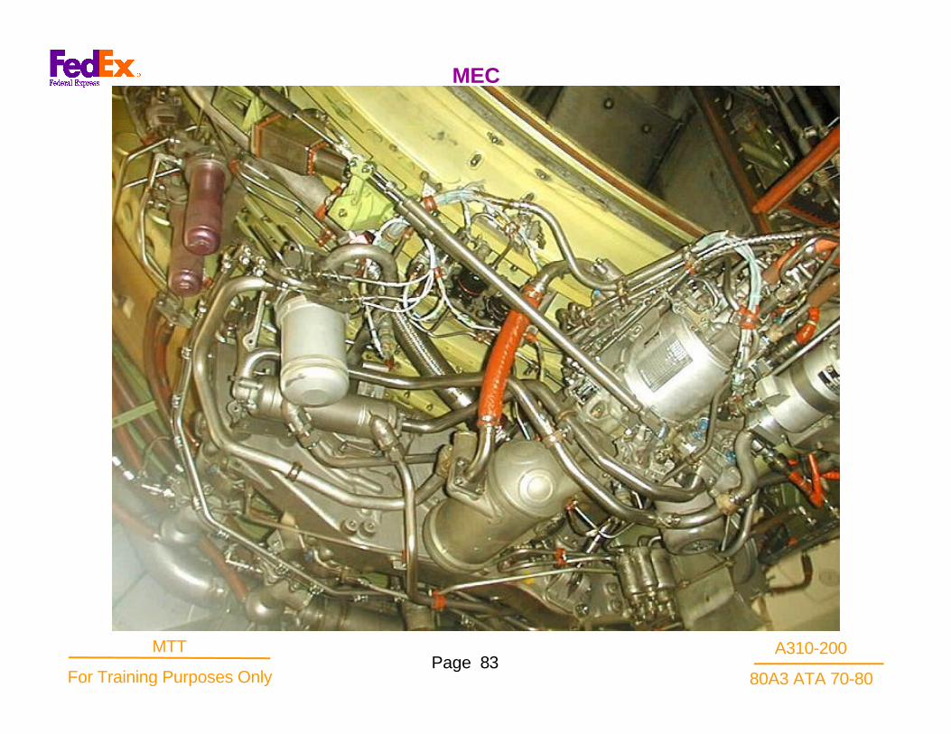
MEC
A310-200
80A3 ATA 70-80Page 83
MTT
For Training Purposes Only
MEC

A310-200
80A3 ATA 70-80Page 84
MTT
For Training Purposes Only
The flowmeter provides an electrical pulse signal toboth the cockpit indicator and the performancemultiplexer (PMUX) proportional to mass fuel flow inorder that fuel consumption can be measured andrecorded. The unit is electrically self energized whendriven by the flowing fuel. On the A310, the flowmeteris supported by a clamp to a bracket at 7:00 on theengine next to the MEC. An electrical connector is alsoprovided near the "fuel in" port.
OperationInlet fuel is directed thru a swirl generator to establish avortex flow that drives the rotor. The rotor is acylindrical, free spinning rotor mounted on ball bearings.The rotor contains two permanent magnets. Onemagnet is in the plane of the start coil. The secondmagnet is near the trailing edge and passes under thesignal blade extension of the turbine. The free spinningrotor generates a start signal, electro-magnetic pulse inthe start coil. A similar pulse is induced in the signalblade -collector ring circuit of the turbine by the aftmagnet to produce a stop pulse in the stop coil circuit.The time lapse between the start and stop pulses isvariable and proportional to the flow rate of the fuel. Theturbine, like the rotor, is bearing mounted to be able toturn but is restrained from spinning by the restrainingspring. The vanes in the turbine react to the swirling fuelflow. Depending upon the mass flow, the turbine will
proportionally windup the restraining spring. Theposition of the single blade forward extension willbe at an angular position commensurate with thespring windup.
A start coil is mounted outside the main housingto pick up the rotating forward magnet. A stopcoil encircling the main housing is energized bythe electromagnetic pulse generated by thesecond magnet of the rotor passing under theextension of the signal blade and collector ringcircuit.
Fuel Flowmeter

A310-200
80A3 ATA 70-80Page 85
MTT
For Training Purposes Only
Fuel Flowmeter

A310-200
80A3 ATA 70-80Page 86
MTT
For Training Purposes Only
The fuel manifold carries the fuel from the MEC to thefuel nozzles. Non-shrouded lines below the lowerpylon fireseal direct the fuel into the fuel flow meterinstalled on the transfer gearbox. Above the lowerpylon fireseal the manifold is shrouded. The main partsare the pylon fuel tube which runs vertically to theunderside of the compressor case. The next part is thefuel tube which carries the fuel horizontally aft to theflange coupling of the lower shrouded fuel manifold.
The shrouded manifold assembly sections each supplyfifteen fuel nozzles through five shrouded fuel nozzlefeeder tube assemblies or tribones. A recent change indesign deletes the outer two knurled nuts at the fuelnozzle end from the tribone assembly and thelockwire from the Hex nut.
The shrouded manifold must be pressure tested at twolevels of pressure. The high tube connections aretested for leaks at 200 psig, while the shroud ischecked at 50-55 psig. No leakage permitted in thehigh pressure fuel line.
The shroud drains through the lower pylon fireseal intothe drain mast module by an interconnecting draintube.
Fuel Manifold

A310-200
80A3 ATA 70-80Page 87
MTT
For Training Purposes Only
Fuel Supply Tubes and Manifolds

A310-200
80A3 ATA 70-80Page 88
MTT
For Training Purposes Only
Carries the fuel from the main fuel manifold to thenozzles.
A single unit that consists of three, jointly connected andschrouded fuel tubes that are connected to threeindividual nozzles.
Fuel schroud and fuel lines pressure checked much thesame as the main fuel manifolds.
Fuel Feeder Manifold

A310-200
80A3 ATA 70-80Page 89
MTT
For Training Purposes Only
Fuel Feeder Manifold

A310-200
80A3 ATA 70-80Page 90
MTT
For Training Purposes Only
Thirty each (30) nozzles that deliver fuel into thecombustor in a spray pattern which provides good lightoff, low emissions and efficient burning at high power .Twenty one nozzles provide both primary flow for light offand secondary flow for high volume fuel needed atpower. Some nozzles do not incorporate primarydischarge flow, but do provide secondary flow for highpower. A green anodized tag identifies the secondaryonly nozzles. Part numbers are etched on the valvebody. Dual flow nozzles contain a check valve, 20 psi +/-2, at the fuel inlet to prevent fuel drainage at engineshutdown. Both types of nozzles contain a flow dividervalve which initiates secondary fuel flow when themanifold pressure exceeds the burner pressure by 320-250 psid. No fuel flow from secondary only nozzlesbelow approximate flight idle speed. The primary andsecondary flows have separate swirl chambers toatomize that fuel. Atomization is aided by air circulationthrough the air shroud at the tip.
Fuel Nozzles

A310-200
80A3 ATA 70-80Page 91
MTT
For Training Purposes Only
Fuel Nozzle
A310-200
80A3 ATA 70-80Page 92
MTT
For Training Purposes Only
A VBV position schedule is provided by a cam in theMEC. The cam position is determined by the VSVfeedback cable position, which in turn is directlyproportional to the engine speed corrected to T2.5.The cam positions a pilot valve controlling MEC inletfuel pressure. As in the VSV system, the fuel pressurewill drive the hydraulic actuators that position theVBV's. A feedback cable will null the pilot valve signalwhen the actuators are in the required position. TheMEC must be rigged to the VBV actuators by afeedback cable adjustment.
The position of the VSV's and the VBV's may bemonitored while the engine is operating using thelinear variable displacement transducer (LVDT)sensors of the Condition Monitoring Kits. The LVDT'sare attached to brackets at prepared bosses andconnected to electrical cables to carry the signal.Indicators in the flight deck will display the respectivesystem position calibrated in degrees or volts of VSVposition and volts of VBV position.
VBV and VSVs

A310-200
80A3 ATA 70-80Page 93
MTT
For Training Purposes Only
VBV and VSVs

A310-200
80A3 ATA 70-80Page 94
MTT
For Training Purposes Only
The components of the VSV System are:VSV Hydraulic Actuators (2)VSV Feedback Cable and Linkage
Variable Stator Vane Actuator (mounted at 3 and 9 o'clock forward flange compressor stator ).
Double acting hydraulic piston. Actuation fluid isfuel at MEC inlet pressure.Fixed stroke limited by head end and end cap.Double seal with seal drain, “Viton B” packing. Sealdrain into rod end fitting boss and fuel line shroud.Rod wiper -Teflon.Rod end bearing provides adjustment for actuatorlength, not field adjustable or repairable.Full open actuator is baseline reference for riggingcompressor VSV’s to MEC.
VSV System

A310-200
80A3 ATA 70-80Page 95
MTT
For Training Purposes Only
VSV Actuator

A310-200
80A3 ATA 70-80Page 96
MTT
For Training Purposes Only
ConstructionThe inner member of the cable is stranded steel wirewith a polished strap spiral wrapped around the strandsto bind them. An end is swaged to the stranded cableeach end. The rods are threaded for rod end bearingattachment. The outer housing is a flexible braidedconduit with a teflon liner inside. The housing isattached to an end fitting which is threaded forassembly of the support tube and to attach to the spliteye type support brackets. The support tubes direct theflex cable into the housing. They are sealed to reduceairflow and passage of contaminates by "0" ring seals.The VBV feedback cable is constructed like the VSVfeedback cable. The principle difference is the length.
Routing on the engineThe feedback cable inner member originates at abellcrank at the nine o'clock position while the conduitstarts by clamping to the lever arm of the feedbackcable reset actuators. It is routed down through thelower pylon fireseal, then to the MEC. The VBVfeedback cable originates at the nine o'clock fan frameposition. It runs down to the lower pylon fireseal thenover to the MEC at seven o'clock.
VSV and VBV Feedback Cables

A310-200
80A3 ATA 70-80Page 97
MTT
For Training Purposes Only
Feedback Cable

A310-200
80A3 ATA 70-80Page 98
MTT
For Training Purposes Only
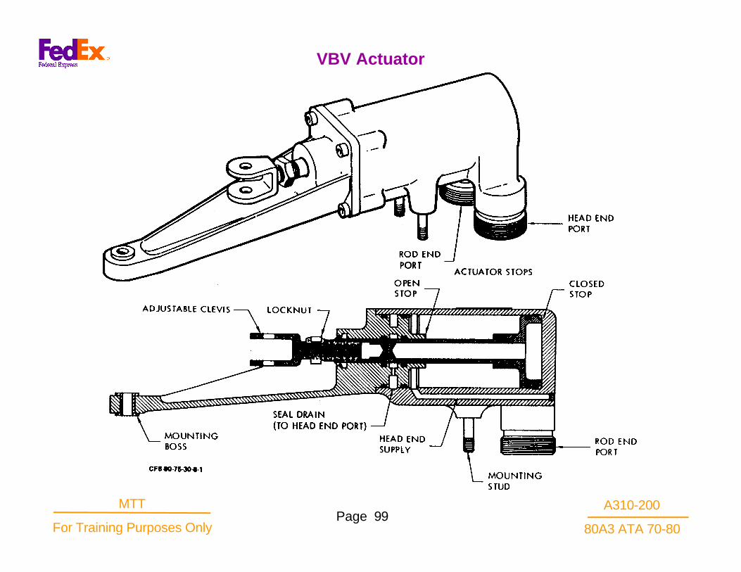
Variable bleed valve actuator
A double acting hydraulic piston using MEC fuel atinlet pressure as the actuation force.
Fixed stroke limited by head and rod end stops.
Dual stage seal with a drain between the first and second stages. The drain is vented to the fuel line shroud.
Rod wiper of Teflon.
Mounted by two studs at one end and bolted througha slip fit bushing at the forward end.
Adjustable clevis on piston rod to provide accurateactuator rigged length. The assembly is not field adjustable.
Full closed actuator is baseline reference for rig of VBV's to MEC.
VBV System
A310-200
80A3 ATA 70-80Page 99
MTT
For Training Purposes Only
VBV Actuator

A310-200
80A3 ATA 70-80Page 100
MTT
For Training Purposes Only
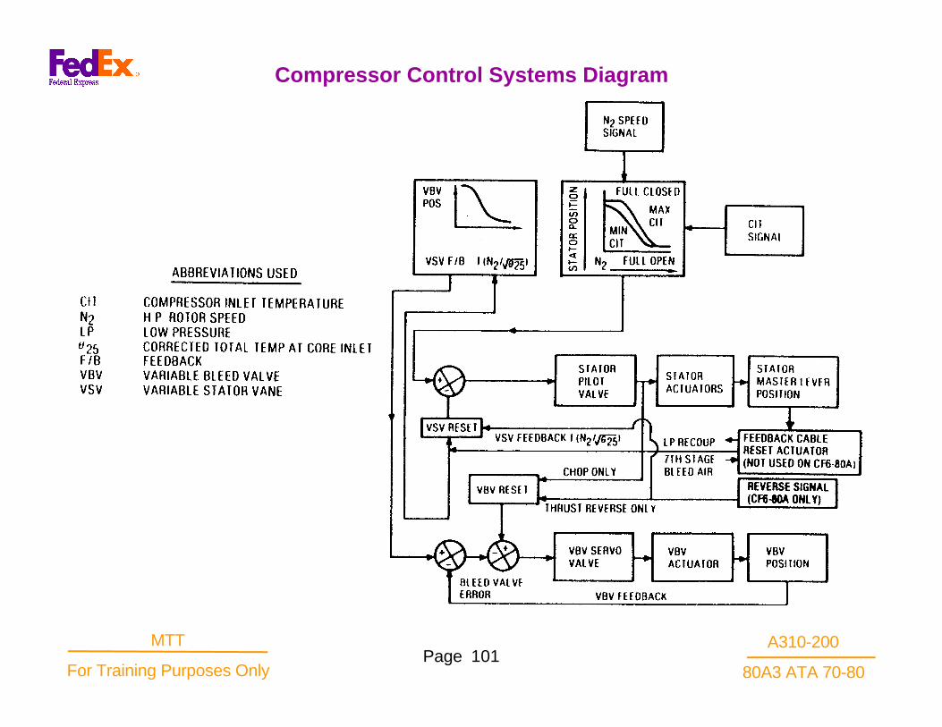
The VSV/VBV reset function, is used during throttlechop. It provides an increased compressor stall marginduring thrust reversing.
The feedback cable reset actuator transientlyrepositions the VSV feedback cable during engineacceleration. When takeoff power is set, the VSV's arereset closed initially and then gradually returned to thescheduled position. This reset action provides partialcompensation for the inherent tendency of fan speedand exhaust gas temperature (EGT) to both overshootinitially and then droop below target at fixed throttle. Italso provides increased compressor stall margin attakeoff.
During a rapid acceleration the clearances in the HPTopen up with resultant loss of efficiency, higher fuel flowrequirements and EGT. Fortunately the seal placementand growth characteristics of the LPT are such as toimprove its efficiency during the same transient. TheLPT can produce more fan speed from a given airflowduring a throttle burst transient than it can with thesame given airflow under steady state conditions. Fanspeed will overshoot the high energy level in the coreengine gas flow.
VSV Feedback Cable Reset System
A310-200
80A3 ATA 70-80Page 101
MTT
For Training Purposes Only
Compressor Control Systems Diagram

A310-200
80A3 ATA 70-80Page 102
MTT
For Training Purposes Only
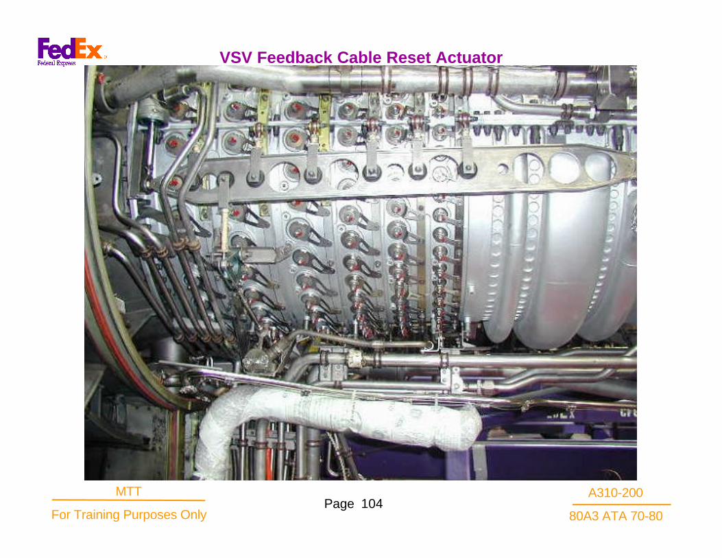
The actuator will sense the transient situation and willmake a change in the feedback cable loop, closing thevanes, reducing the airflow, fuel flow, and EGTovershoot, while the N1 will continue to be driven toacceptable speeds.
Seventh stage compressor bleed air is ducted throughthe actuator to heat the primary tube and secondary rodsensor unit. The sensor tube and rod can be comparedto a thermal model of the engine. With increases of N2,the 7th stage bleed is being compressed and heated.The flow through the actuator increases in temperatureand BTU content causing a thermal transient conditionto exist here too.
The primary tube is free to expand to the left but iswelded or brazed to the secondary rod on the right end.The secondary rod cannot expand as rapidly as theprimary tube. It is much heavier in cross-section. Thereis then a differential in their respective lengths duringthe transient similar to that dimensional change seen inthe engine between the stators and the rotors.
A bracket arm supporting the upper end of the VSVfeedback cable sheath is pivoted to the outer case ofthe actuator and moved at the input pivot by theexpansion of the primary tube. The bracket arm swingscounterclockwise shortening the feedback cable loop on
an acceleration. The bracket arm is returned tonull, with the passage of time, as both sensorunits assume a new stable dimension at thehigher temperature. But in growing to the newlength, there is a time delay between the twoelements of approximately 180 to 300 secondsin the maximum condition.
When the secondary rod becomes the sametemperature as the primary tube, it has .expanded to the right, pulling with it the primarytube and the bracket arm. It, the secondary rod,is bolted firmly to the housing on the left and isfree to move axially within the bore of thedischarge air flow on the right.
The closure of the vanes reduces the powerrequired of the HPT to drive the compressor. Ittends to cause overspeed in the rotor but it'scorrected in the MEC by governor action on thefuel metering valve to reduce fuel flow. Thereduced fuel flow reduces EGT. The improvedtransient efficiencies in the LPT use the reducedair flow to accelerate the fan to the target N1without overshoot.
VSV Feedback Cable Reset Actuator

A310-200
80A3 ATA 70-80Page 103
MTT
For Training Purposes Only
VSV Feedback Cable Reset Actuator
A310-200
80A3 ATA 70-80Page 104
MTT
For Training Purposes Only
VSV Feedback Cable Reset Actuator

A310-200
80A3 ATA 70-80Page 105
MTT
For Training Purposes Only
PMC

A310-200
80A3 ATA 70-80Page 106
MTT
For Training Purposes Only
The fail fixed mode will fix or maintain whatever amountof down trim has been made on the main enginecontrol. This could range from zero to maximum downtrim. The effect of "fail fixed" activation would requirethe pilot to manually adjust the throttle position to obtainthe rated N1 rpm. The amount of adjustment would beminor since the MEC contains a HM T2 and Poc 3Dcam, biasing the throttle speed signal to provide acorrected N2 speed of the engine. This will permit aclose approximation of the required throttle position togive the N1 required. It is expected the extra throttleadjustment needed could be as little as 2° or 3° in theretard direction, depending on ambient conditions.
A switch(s) in the cockpit permit the pilot to select thePMC enable (On), or disable (Off). The switches areidentified differently on the different aircraft applications,but the interface with the PMC is the same. If the PMC(s) is/are selected "off' or "inop.", engine thrustmanagement is then entirely controlled by manualthrottle positioning. This switch selection removescontrol from the MEC torque motor, preventing anydown trimming operation and releases any fail-fixedlatch, if previously set. All other internal/externalfunctions of the PMC continue.
Fail Fixed Mode

A310-200
80A3 ATA 70-80Page 107
MTT
For Training Purposes Only
Power Management Control

A310-200
80A3 ATA 70-80Page 108
MTT
For Training Purposes Only
The PMC is a limited authority digital electronic trimcontrol. The PMC is given an analog signal of throttleposition via a resolver installed under the pilots controlstand. The PMC also receives a combination of up to 6aircraft bleed status input signals. Depending on aircraftapplication, other inputs of ambient pressure, machnumber ,total air temperature, impact pressure, andtotal pressure are provided. The PMC uses thesevalues to compute the required N1 command for thecurrent day conditions and flight mode. The PMC willprimarily use the aircraft inputs, performing statuschecks, range checks, etc. and compare this data withinput data of the PMC sensors.
If the comparison shows agreement, then the PMCfunction of comparing actual N1 with the calculated N1command will activate the torque motor drive circuit andtrim the MEC downward, reducing N1 speed. Thesystem dynamics cause the trimming to occur so thatno overshoot of N1 command will be evident-
A disagreement between redundant sensed values willcause the PMC logic to discard the discrepant value,basing its computations on any like sensor values inagreement. The PMC will use it's engine mountedsensor data should the aircraft source fail the input testselection logic. The PMC will alert maintenance of anydiscrepancy on the aircraft maintenance panel.
Acceleration to takeoff power and the subsequentaircraft takeoff maneuver will cause a transientcondition to develop in the thrust ratings. Normalchanges in Mn, T2, Po and inlet recovery effect onthe N1 rpm will see the thrust managementcomputer updating the ratings calculations andadjusting the target bug. The PMC dynamics willdrive the torque motor to adjust the MEC trimadjustment to compensate for the transient. Theactual N1 will adjust as the target bug is updatedand a "hands-off' throttle takeoff is accomplished.
Power Management Control (PMC)

A310-200
80A3 ATA 70-80Page 109
MTT
For Training Purposes Only
Power Management Control

A310-200
80A3 ATA 70-80Page 110
MTT
For Training Purposes Only
The PMC unit weighs about 40 pounds. Much of theweight is accounted for by the aluminum flake filledsilicone rubber potting compound to protect thecomponents against vibration shock, and heat.
The PMC receives dual ARINC 429 digital word signalsfrom the aircraft. The PMC can generate a Machnumber schedule in the absence of the aircraft digitalwords to enable computation of thrust ratings. The PMCsubtracts impact pressure from total pressure to obtainPo, the altitude value.
Power for PMC operation is from the engine mountedcontrol alternator except in the ground test mode. ThePMC uses aircraft 28VDC to energize the "fail fixed”solenoid.
Ground test of the PMC uses 115V 400Hz from theaircraft power supply. When operating, the controlalternator output disables the ground power test circuit.A thermal relay protects the PMC from excessivetemperatures, deactivating ground test when it gets toohot.
PMC INPUTSAircraftMach number (Mo) (A310), source ADC'sTotal air temperature (TAT), source ADC'sTotal pressure (Pt), source ADC's.Impact pressure (a), source TCC (A310) note: thePMC computes Po from inputs of a and PtDiscretes: enable/disable signal, bleeds status inputs,ground test signal/power input, TLA resolver ,
Enginecontrol alternator power/N2 signalAmbient pressure (Poc)Ambient (inlet) temperature (T1.2)N1 actualN1 demand (N1 DMD) metering valve feedback fromMEC
PMC OUTPUTSAircraftN1 actual (digital) (N1 ACT) to aircraft N 1 indicatorCommand fan speed (N1 CMD) to aircraft N1indicatorMaximum N1 limit (N1 MAX) to aircraft N1 indicatorPMC fault data to AIDS (A310)PMC fault signal to cockpit panel lite
EngineTorque motor current (TMC) to MECData retrieval (from J7 connector)
PMC

A310-200
80A3 ATA 70-80Page 111
MTT
For Training Purposes Only
Power Management Control System

A310-200
80A3 ATA 70-80Page 112
MTT
For Training Purposes Only
Within the A3l0 cockpit the N1 gage is a dial type.They are a target bug, a command needle, actual N1,digital N1, overspeed trip, overspeed redline, and selftest capabilities (bite). The A310 aircraft, uses a single"engine trim" (FAULT -OFF switch) to control thePMC's of both engines. The switch is located on theoverhead panel. Identified system and componentfaults can recalled using a portable test unit pluggeddirectly into the aircraft digital data buss, or on certainmodel aircraft, read directly from the aircraft AIDSsystem. The connector is on the Flight DeckMaintenance panel. A digital display is provided on theMaintenance Panel to identify limited PMC faults.
The A3l0 aircraft is slightly different in the the primedigital input to the PMC is from the aircraft thrustcontrol computer (TCC). The TCC provides Machnumber (Mo), total air temperature (TAT), impactpressure (Pq), total pressure (Pt). The PMC usesthese values to compute the N1 command and tocompare with its own T2 and Po sensor values.
The aircraft bleed configuration effect on N1 target isprogrammed by the Thrust Control Computer. Amanual throttle adjustment will be required to the newtarget.
Aircraft Integration

A310-200
80A3 ATA 70-80Page 113
MTT
For Training Purposes Only
Power Management Control System

A310-200
80A3 ATA 70-80Page 114
MTT
For Training Purposes Only
The PMC operation can be checked on the ground.When the engine is shutdown, an aircraft PMCground test switch (Trim Test) on the flight decksupplies 115V 400 Hz signal which activates the PMCground test program.In ground test, the PMCcomputes N1 command as in normal operation, andsets the N1 actual equal to the N1 command andprovides digital outputs to the aircraft N1 indicator .When the throttle levers are moved, simultaneouslythe N1 actual and N1 command pointers on indicatormove accordingly. This test provides a comparison ofthe PMC system operation of one engine with respectto the other. During this ground check, the PMC selfmonitoring system is fully operational and indicatesany detected faults. The NVM maintains 7 sets of theabove data, resulting from the last 7 flights (power on/ power off). The last set is addressable while inground test mode with the PMC disabled. The sixremaining sets of data are available from the J3 testconnector . The PMC has a thermal switch whichprevents extended ground test operation in hot dayambient conditions, with settings of 165 deg.Fmaximum, or 100 deg.F for limited 30 minutes ofoperation.
The non-volatile memory (NVM) within the PMCstores a set of data which includes: 5 maintenanceand system discrete words 8 sensor values (N1, N2,T1l.2, Po, TLA, N1DMD, Mo, and TMC).
sensor values (N1, N2,T1.2, Po, TLA, N1DMD, Moand TMC)
The NVM maintains 7 sets of the above data,resulting from the last 7 flights (power on / power off).The last set is addressable while in ground test modewith the PMC disabled. The six remaining sets of dataare available from the J3 test connector .
Ground Test

A310-200
80A3 ATA 70-80Page 115
MTT
For Training Purposes Only
Aircraft/Engine Interfaces A310

A310-200
80A3 ATA 70-80Page 116
MTT
For Training Purposes Only
The system provides a fan discharge cooling air flowinto the core engine compartment and to the lowpressure turbine case cooling manifold. The two areasbenefit from the cooling flow at different conditionsduring the aircraft flight so a selective use of the samecooling air source is possible through a manifold with aone and two shutoff valves.
The core engine develops higher compartmenttemperature during takeoff thrust and climb thrust,especially at lower altitudes, therefore corecompartment cooling requirements place a greaterdemand on the cooling flow available. During thisperiod the cooling air valves direct most of the air tothe under cowl cooling manifolds. At the cruisealtitudes the engine is throttled back, reducing the coreengine and compartment temperatures and permittinga reduction in cooling air flow.
The low pressure turbine cooling manifold is suppliedwith a reduced flow through its normally "closed" aircontrol valve at takeoff and climb modes up to about20,000' altitude. Above this altitude the valve will opento provide an increased cooling flow to the LPT case.The increased cooling flow will cause the case to cooloff and shrink somewhat. The shrinkage will close upthe seal clearances producing an improved efficiencyat the cruise altitudes which reduces the fuel burn.
Active Clearance Control System

A310-200
80A3 ATA 70-80Page 117
MTT
For Training Purposes Only
Active Clearance Control System

A310-200
80A3 ATA 70-80Page 118
MTT
For Training Purposes Only
The cooling air valves are of similar externalappearance but one is normally open and the other isnormally closed or reduced flow area. They are madeof aluminum, 3 1/2" duct diameter .
The core cowl cavity cooling air valve is spring loadedopen, providing maximum flow at lower altitudes.When the altitude sensor switches above 20,000’, itapplies a CDP signal to the signal port of the air valve.CDP flowing through the regulator orifice pushes thevalve closed against the opposition of the openingspring. The flow area is thereby reduced to the corecompartment.
The LPT air valve is spring loaded in the closeddirection. The CDP signal introduced above 20,000' tothe core cavity cooling air valve is also applied to theLPT air valve through a similar regulator orifice. CDPpressurization of the actuator chamber forces the valveopen thereby increasing the cooling flow to the LPTcase cooling manifold. The valve at T.O. flows .5ppsand at 35,000' cruise it also provides .5pps air flow.The A310 installation uses a valve with an electricalposition switch in a circuit of the altitude sensingsystem to operate a disagree cockpit light.
Cooling Air Valve

A310-200
80A3 ATA 70-80Page 119
MTT
For Training Purposes Only
Cooling Air Valve

A310-200
80A3 ATA 70-80Page 120
MTT
For Training Purposes Only
The altitude sensor valve controls the switching signalto the cooling air valves. Compressor dischargepressure is applied to both cooling air valves by aselector valve in the altitude sensor when an aneroiddetects altitudes above 20,000’ +/- 4,000". Below thisaltitude the valve switches to the low altitude position.The CDP source is a port on the CRF at 3 o'clock nearthe forward flange.The aneroid bellows will expand athigh altitude pushing a lever against a poppet valve. Atthe preset 20,000', the poppet is closed to pressurizethe chamber below the smaller piston head of theselector valve. The pressurized piston drives theselector valve upward to its travel limit. The upperpiston travel opens a port for CDP flow to the cooling airvalves switching them to their opposite position. Theaneroid chamber has a fail indicator pin which protrudesabove the vent housing if the aneroid bellows has failed.It is observed during ground cowl open inspection.
The selector valve spool also provides a failure indicatorpin which is exposed above the housing if the valve ispressurized or stuck open. The valve is bolted to abracket on the compressor case in the 12:00 o'clockposition, about stage 6.
Altitude Sensor

A310-200
80A3 ATA 70-80Page 121
MTT
For Training Purposes Only
Altitude Sensor

A310-200
80A3 ATA 70-80Page 122
MTT
For Training Purposes Only
Two vendors have qualified a starter for the CF6-80engine, Garrett and Hamilton- Standard. The Hamilton-Standard starter employs an adapter ring between itsmounting flange and the accessory gearbox mountflange
The starters are single stage air turbines turningthrough a planetary gear train to reduce the output shaftspeed by a factor of 13.5 to 1 on the Garrett model, andat 10.45 to 1 for the Hamilton Standard model.
The CF6-BOA1/A3 starter is installed to the fanmounted AGB at 6 o'clock on the forward surface. Italso employs the hinged "V" band clamp.
Self contained splash lubrication system. Garrett starteroil capacity is 800 c.c. limited by a stand pipe andoverflow port. The Hamilton-Standard starter has a 350c.c. oil capacity. Two fill ports, one on each side,improve access for service. Drain plug incorporates apermanent magnet check valve. The drain plug housingprovides a check valve.
Start System

A310-200
80A3 ATA 70-80Page 123
MTT
For Training Purposes Only
Garrett and Hamilton Standard Starters

A310-200
80A3 ATA 70-80Page 124
MTT
For Training Purposes Only
The starter is duty cycle limited due to the limitationsof the bearings and lube supply.Operating cycle is 5minutes with 2 minutes cooling. After the first cycle,repeat operation requires a 10 minute cooling periodbetween each cycle. The starter assist to the enginebegins at zero N2 when air flow at recommendedpressure is initiated. (25-55 psi). Core enginemotoring speed maximum 22-26% N2. Engine fuel-onto make a start at 15% N2. Starter centrifugal clutchdisconnect capability at 39-40% N2, re-engage at10% N2.
Starter

A310-200
80A3 ATA 70-80Page 125
MTT
For Training Purposes Only
Starter Section

A310-200
80A3 ATA 70-80Page 126
MTT
For Training Purposes Only
A butterfly valve controls the flow of air to the starter.It has two positions open and closed. Normallyoperated by pneumatic pressure switched by asolenoid check valve. A manual override "T" handle isprovided to open the valve in case of a valve failure.
The valve is installed to a bracket on the inlet cowl atapproximately 7 o'clock.
The butterfly valve is fitted to a hollow shaft, which bycrank and connecting rod is connected to an unequalsized double diaphragm actuator. The closing forceon the shaft is exerted by the closing torsion springand pneumatic pressure on diaphragm "B" whenthere is duct pressure. The pressure differenceacross the larger diaphragm is controlled by theposition of the solenoid vent valve. When energized,the ball check valve will seat on the lower port,venting the outer chamber of diaphragm " A " toambient through the upper port. The larger size ofdiaphragm "A" will overcome "B" diaphragm and theclosing spring forcing the actuator to turn the shaftand butterfly valve to "open".
Manual operation is accomplished by "T" handlemovement. It is a two step procedure. The handle
must be pulled axially to vent the actuatorchambers to ambient, neutralizing the actuator.The actuator chamber pneumatic resupply islimited by the regulator orifice so the "T" handleventing is effective. Then it is necessary to turnthe "T" handle clockwise applying enough forceto overcome the closing torsion spring. Turn tothe open position and hold throughout themotoring period. To close, reverse the steps.
Starter Control Valve

A310-200
80A3 ATA 70-80Page 127
MTT
For Training Purposes Only
Starter Air Valve

A310-200
80A3 ATA 70-80Page 128
MTT
For Training Purposes Only
A new low energy ignition exciter with a repetitivedischarge spark ignites the fuel in the combustor whichignites a self sustaining flame. They are installed onthe fan stator on shock absorbing brackets at the 3:30position. A soldered aluminum case, grey in color,charged with dry air, encloses the capacitor chargingand discharging circuits. The internal components arepotted..
Two electrical connectors on opposite ends of the boxprovide; a power supply input of 110 VAC, 400Hzinput, and low voltage output of 1.5 joules per sparkwith a spark rate of approximately 1 spark/second.The box contains circuit elements to isolate the unitfrom interference with the aircraft electronics, step uptransformers, full wave rectifiers to charge the storagecapacitors, and arc gaps which ionize to break downthe resistance to discharge the storage capacitors.The high voltage connector has a replaceable goldplated pin deeply recessed within the connector.
The unit is rated for continuous operation.
Ignition System

A310-200
80A3 ATA 70-80Page 129
MTT
For Training Purposes Only
Ignition Exciters

A310-200
80A3 ATA 70-80Page 130
MTT
For Training Purposes Only
THIS PAGE INTENTIONALLY LEFT BLANK

A310-200
80A3 ATA 70-80Page 131
MTT
For Training Purposes Only
Ignition Leads

A310-200
80A3 ATA 70-80Page 132
MTT
For Training Purposes Only
The plug provides a surface gap for the discharge of thehigh energy of the ignition exciter in order to ignite thefuel in the combustor. The igniter plugs are installed at 3and 4 o'clock on the compressor rear frame aft of thefuel nozzles. The igniter is a threaded, type 4F, surfacegap type design. There are two types available, onehaving a Beryllium Oxide insulator, and one with asilicone nitrate insulator.
WARNINGThe beryllium oxide plugs require special handling anddisposal.
The beryllium plugs are identified by two blue bandsaround the circumference of the terminal end bushing.The silicone nitrate plug requires no special handling ordisposal. Air cooling holes are provided in the groundelectrode shell and in the center electrode for maximumcooling efficiency. A convective two-piece coolingschroud is wraped around the installed plug/leadconnection. The schroud traps the discharge cooling airfrom the aft lead and directs the air down over thesurface of the plug, thus helping to cool the igniter andincrease life. The cooling air exits the schroud adjacentto the threaded coupling on the compressor rear frame.The schroud also ensures that the silicone seal in theterminal end remains below 450 deg. F (230 deg. C)
Igniter Plugs

A310-200
80A3 ATA 70-80Page 133
MTT
For Training Purposes Only
Igniter Plug

A310-200
80A3 ATA 70-80Page 134
MTT
For Training Purposes Only
The CF6 oil system is a non-regulated type system,meaning that the system does not have an oil pressurerelief valve to maintain oil pressure at a steady valueregardless of engine RPM. The oil pressure of a CF6engine "follows the throttle" and is variable givendifferent ambient conditions. Pressure in the system isdetermined by the pumping capacity verses therestriction of the passage of the oil through thenozzles. With this type of oil system, the operator canquickly determine the ability of the system to deliverthe correct volume of oil to each part of the engine.
The central lube and scavenge pump has onepressure element for the entire engine. Separatescavenge elements remove oil from each enginecavity/component and return the oil to the tank in onecommon scavenge discharge line. In route to the tankthe scavenge oil passes a temperature sensor, amagnetic chip detector and lastly the fuel-oil heatexchanger. The nominal flow rate of the oil is 16.75gallons per minute (gpm) (63.4 liters). A 46 micronsupply filter and a 15 micron scavenge filter are used.The engine will function satisfactorily with oilconforming to GE Specification No. D50TF1, Class Aor Class B. Oils conforming to MIL-L-7808 and MIL-L-23699A are consistent with this GE specification. Oilconsumption rate is expected to be approximately 0.07gph = 0.26 liter with maximum rate set at 0.2 g/h 0.76liter, providing an estimated flight length of 16 hours.
Lubrication System

A310-200
80A3 ATA 70-80Page 135
MTT
For Training Purposes Only
A - 310
Engine Oil System Functional

A310-200
80A3 ATA 70-80Page 136
MTT
For Training Purposes Only
This oil tank is the same as the CF6-6/-50/-45 engine.It is a cylindrical aluminum fabrication with sphericaldomes. The tank is installed to the fan stator at 4o'clock by a shock absorbing system. The tank issupported by two mounting rings. The rings are hingebolted to the fan stator brackets at the top. Twospring loaded turnbuckles, at the lower clevises, pullthe mounting rings against center braces. Rubberizedfabric pads reduce fretting at the center braces. Thetank volume is 31.6 quarts U.S., 24 quarts is oil, thebalance is pressurizing air volume. The low oil level isindicated by either a dipstick on the filler cap or by amagnetic float type sensor installed to a flanged porton the upper housing. Ports on the tank provide for:
Oil FillManual fill. A spring loaded, lever type handle turns the filler cap to remove it. A relief valve isincorporated in the cap. It relieves at 35 psid andreseats at 23 psid.
Pressure fill and overfill ports are provided for connection to a service cart.
Oil supply out a flanged port at the bottom of the tank.
Drain plug is along side the supply port. Scavenge oilinlet power is a flanged type on the side of the upperhousing. Vent port is a threaded boss to receive thepressurizing valve. The pressurizing valve maintains 7-9 psid pressure in the tank. The pressure bleeds off tothe "A" sump through a vent manifold routed over thefan case to strut #11 of the fan frame. Completeventing of the tank will occur approximately 5 minutesafter engine shutdown. Air-oil separation isaccomplished by a vaned vortex generator thatreceives the incoming scavenge air-oil. The oil swirlsthrough the vortex generator and against the sides ofthe tube to breakup the oil bubbles. The air vents outthe top through the pressurizing valve.
Oil Tank

A310-200
80A3 ATA 70-80Page 137
MTT
For Training Purposes Only
Oil Tank

A310-200
80A3 ATA 70-80Page 138
MTT
For Training Purposes Only
The lube and scavenge pump provides pressurizedfiltered oil to the supply manifold, and removes oil fromthe sump to recirculate It. Two pumps are certified. Thenewer pump uses the same casting but deletes the inletscreen port, extension drive shaft and carbon seal withdrain and cold start relief valve.
Mounted to the forward face of Accessory Gearbox at6:30 o'clock by "V" band clamp, safety wired.
Lubricated spline drive.
Shear section 1500-2000 in lb.
Positive displacement vane type pump with oneelement for supply and five elements for separatescavenge areas.
Inlet screens, 26 mesh, at every inlet contain permanentmagnetic chip detector plugs, except the supply inletscreen.
"B" element oil injection -bleed oil supply to aft "B" sump finger screen plug from supply filter dischargepressure port. Keeps "B" pump element wet to maintain pumping capability to avoid excessive gulping indications and oil loss at aft "B" sump drain.
Bypass, relief, and check valves provided for:
Inlet screen removal, oil supply port.
Filter removal.
Filter bypass 40-50 psid, F.O. 70 psid
Cold start relief for pressure transducer at 300 psid, F.O. 400 paid reseats at 275 psid
Anti - static leak at 2.5 to 6 psid
Oil System

A310-200
80A3 ATA 70-80Page 139
MTT
For Training Purposes Only
Lube and Scavenge Pump
LUBE SUPPLY D ISCHARGE
LUBE SUPPLY INLET
SCAVENGE INLETS

A310-200
80A3 ATA 70-80Page 140
MTT
For Training Purposes Only
Supply pump element
Inlet pressure head of 8.5 to 10.5 psi.
Output of 16.75 gpm at 70 psia.
Supply filter is a 46 micron, cleanable, metal. No bypassindication is furnished, 40 psid. It is the secondary filterin the lube system.
Five separate scavenge return ports. Scavenge pumpelements remove an air-oil mixture developing 85 psidat 100% N2 in common scavenge discharge.
A pump designed specifically for the 80 engine willeliminate the front drive spline used for speed indicationon the -50 and the cold start relief valve. It alsoremoves the supply inlet screen service shut-off valveand eliminates the threaded plug associated with theinlet screen, however, the screen will be maintained.
Sump Pump Element

A310-200
80A3 ATA 70-80Page 141
MTT
For Training Purposes Only
Sump Pump Element

A310-200
80A3 ATA 70-80Page 142
MTT
For Training Purposes Only
The permanent magnet is able to attract bearingparticles carried in the scavenge oil. By frequentinspection, early detection of bearing failure should bepossible. The actual bearing at fault must be identifiedby a magnet and screen check of the L & S pump toisolate the sump with the problem. The magnet islocated in the common scavenge line between the L &S pump and the scavenge filter. A permanent magnet isattached to a round, knurled knob for removal. Theprobe is retained by a bayonet-type, over-center lockingconnection into a housing containing a check valve toprevent oil loss at removal.
Master Magnetic Chip Detector

A310-200
80A3 ATA 70-80Page 143
MTT
For Training Purposes Only
Master Chip Detector

A310-200
80A3 ATA 70-80Page 144
MTT
For Training Purposes Only
Provides the capability to remove particles larger than15 micron from the scavenge oil. If clogged there is abypass relief valve to continue full flow of oil around thefilter element. The filter is mounted to a bracket boltedto the aft left side of the AGB.
Filter head contains inlet and discharge ports, pressuredifferential ports to indicate filter clogging whenattached to a differential pressure switch, a filterremoval shutoff valve and the filter bypass relief valve.The head also provides a grooved recess for the filterbowl sealing "0" ring, and an anchor screw for lockwire.
The filter bowl contains a boss to center the filterelement, the "0" ring sealing surface on the open lip,and the threads for engagement to the head. Anexternal boss provides a shoulder by which ascrewdriver shank can apply removal torque. Somecustomers have purchased a filter bowl without theremoval wrenching feature. A strap wrench may beneeded to remove that type bowl.
The filter element is a disposable pleated type of 15micron. The element is reversible. It is a polyestermedia supported by an inner and outer layer of screenwire. End caps are cemented to the screen wiresupports.
Scavenge Oil Filter
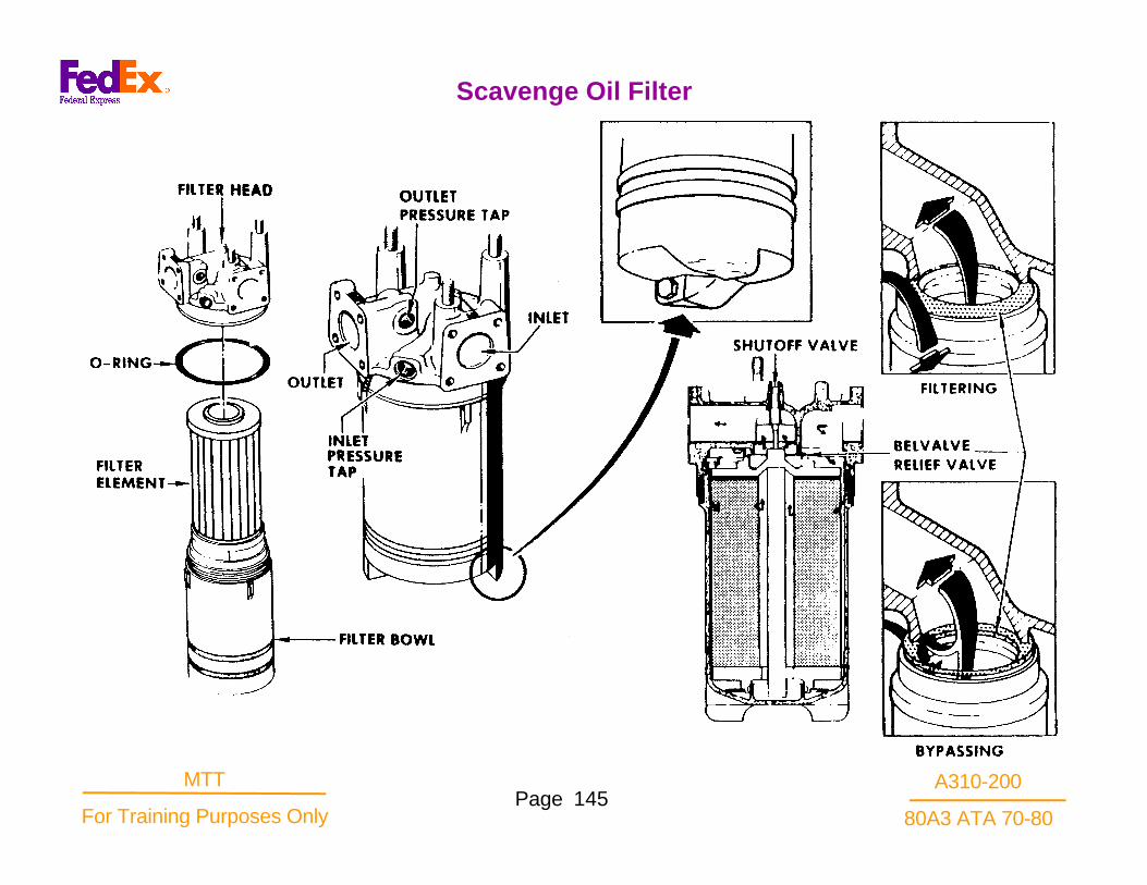
A310-200
80A3 ATA 70-80Page 145
MTT
For Training Purposes Only
Scavenge Oil Filter

A310-200
80A3 ATA 70-80Page 146
MTT
For Training Purposes Only
The accelerometer is a rugged device, no moving parts,using piezoelectric crystals and an inertial mass toproduce an electrical change in the charge level betweentwo conductors proportional to the severity of vibration.The primary accelerometer is on the No.1 bearingsupport housing within the A sump. The lead connectoris on the fan frame at strut No.5 in the core enginecompartment.
Life expected to be 10,000 hours or better
Low signal strength requires specially shielded leadssecurely supported to avoid and prevent externally induced signals.
Signal conditioner (charge amplifier) required to process signal to usable strength for meter display.
Highly directional, sensitive only parallel to axis of assembly screw.
Inertial mass alternately squeezes and releases pressure on wafers of piezoelectric materials in phase with rotor imbalance or vibration.
Collectors receive electrical charges produced by piezoelectrical crystals. Alternate layers connect to opposite leads. Output level or charge level so low itis difficult to consider it a current.
Alternate N1 accelerometer
An alternate accelerometer can be mounted tospecial purpose pad on the fan frame below the3:00. The alternate N1 accelerometer.has asensitivity of 125 pc/g.
Accelerometer

A310-200
80A3 ATA 70-80Page 147
MTT
For Training Purposes Only
Alternate N1 Accelerometer

A310-200
80A3 ATA 70-80Page 148
MTT
For Training Purposes Only
The N2 vibration sensing accelerometer is mounted onthe forward side of the flange between the CompressorRear Frame and the Compressor Stator Case, at10:00. It is mounted to a bracket externally and isconnected by a hard lead to the junction connector .
Low signal strength requires specially shielded leads securely supported to avoid and prevent externally induced signals.
Signal conditioner (charge amplifier) required to process signal to usable strength for meter display.
Highly directional, sensitive only parallel to axis of assembly screw.
Inertial mass alternately squeezes and releases pressure on wafers of piezoelectric materials in phase with rotor imbalance or vibration.
Collectors receive electrical charges produced by piezoelectrical crystals. Alternate layers connect toopposite leads. Output level or charge level so low itis difficult to consider it a current.
N2 Accelerometer

A310-200
80A3 ATA 70-80Page 149
MTT
For Training Purposes Only
N2 Accelerometer

A310-200
80A3 ATA 70-80Page 150
MTT
For Training Purposes Only
The compressor inlet temperature sensor sensesboth pressure and temperature within the samehousing.
Incorporates a direct Pt pressure probe inserted intothe airstream along with a chromel/constantthermocouple
The electrical temperature output is provided to anintegral electrical connector on the body of theprobe.
The pneumatic output is provided through athreaded port on the body of the probe.
Compressor Inlet Temperature/Pressure (P/T2.5)

A310-200
80A3 ATA 70-80Page 151
MTT
For Training Purposes Only
Compressor Inlet Temperature/Pressure Sensor (P/T2.5)

A310-200
80A3 ATA 70-80Page 152
MTT
For Training Purposes Only
Pressure obtained from the inlet to the low pressureturbine is used to provide a parameter to helpdetermine the power performance of the core engine.P4.9 pressure can be compared to compressor inletpressure (P2.5) to develop a value of Engine PressureRatio (EPR).
The single probe is installed into a boss on the LPT 1ststage turbine nozzle case. There are three availablebosses for this purpose. Generally the probe isinstalled at the 3:30 position, with the bosses at 4:00and 1:00 plugged. These two additional ports can beused for borescope inspection and as additionalpositions to measure total pressure at engine test.
On the probe stem there are four inlet ports directedtoward the gas flow. The mounting flange has two boltholes located off the center line to assure the ports arecorrectly oriented. The probe stem enters the outerhousing containing the coiled manifold, which absorbsvibration and withstands the thermal expansion andremoval forces.
Low Pressure Turbine Inlet Pressure (P4.9)

A310-200
80A3 ATA 70-80Page 153
MTT
For Training Purposes Only
P4.9 Pressure Probe

A310-200
80A3 ATA 70-80Page 154
MTT
For Training Purposes Only
The T5 sensor is mounted at the 5:30 position on theTurbine Rear Frame. A separate cable harness isprovided leading to an interface bracket on the left sideof the compressor case at the 9:00 position.The probe is designed as an integral unit consisting oftwo chromel-alumel thermocouples. The twoimmersion depths, one depth for ID airflow sensingand one depth for OD airflow sensing. The unit hasstud type terminal connectors, one large chromel andone smaller alumel. The two thermocouples in thesensor are paralleled inside the probe to provide anaverage flow temperature signal of the exhaust gases.The EMF output of the type K thermocouples isplus/minus 2.2 deg.C.
Low Pressure Turbine Discharge Temperature

A310-200
80A3 ATA 70-80Page 155
MTT
For Training Purposes Only
T5 Sensor

A310-200
80A3 ATA 70-80Page 156
MTT
For Training Purposes Only
The variable stator vane position transducer is avariable ratio transformer. It is similar to a conventionallinear differential transformer except for the addition ofa reference winding which serves, by a self cancelingprinciple, to minimize temperature induced gainchanges. The linear variable displacement transducer(LVDT), as it is commonly referred, is attached to themaster arm of the variable stator system andmeasures the travel/position of the entire system as ittranslates open/closed in relation to the compressorcase. Displacement of the transducer moves theinternal transformer core to establish varioustransformer phase relationships.
VSV Linear Displacement Transducer (LVDT)

A310-200
80A3 ATA 70-80Page 157
MTT
For Training Purposes Only
VSV LVDT

A310-200
80A3 ATA 70-80Page 158
MTT
For Training Purposes Only
The variable bleed valve position transducer is avariable ratio transformer. It is similar to a conventionallinear differential transformer except for the addition ofa reference winding which serves, by a self cancelingprinciple, to minimize temperature induced gainchanges.The linear variable displacement transducer(LVDT), as it is commonly referred, is attached to oneof the bleed doors of the variable bleed valve systemand measures the travel/position of the entire systemas it translates open/closed in relation to the fan frame.The transducer is mounted between the aft inneracoustic panel mount bracket, and the bleed doorclevis bolt at the 3:00 position. Displacement of thetransducer moves the internal transformer core toestablish various transformer phase relationships.
VBV Linear Variable Displacement Transducer (LVDT)

A310-200
80A3 ATA 70-80Page 159
MTT
For Training Purposes Only
VBV LVDT Installation

A310-200
80A3 ATA 70-80Page 160
MTT
For Training Purposes Only
The compressor discharge temperature sensor isdual chromel / alumel thermocouple located at the11:30 position of the compressor rear frame.
The sensor has dual output leads encased withinceramic, enclosed by metal tube, or lead. The sensorassembly is preformed for the engine application towhich it is installed. The lead is routed forward to abracket on the compressor case at the 9:00 position.The dual connector facilitates individual outputs to thePMUX as well as a temperature signal to the aircraftEnviromental System in controlling the High PressureBleed Valve operation.
Compressor Discharge Temperature Sensor (T3)

A310-200
80A3 ATA 70-80Page 161
MTT
For Training Purposes Only
T3 Sensor
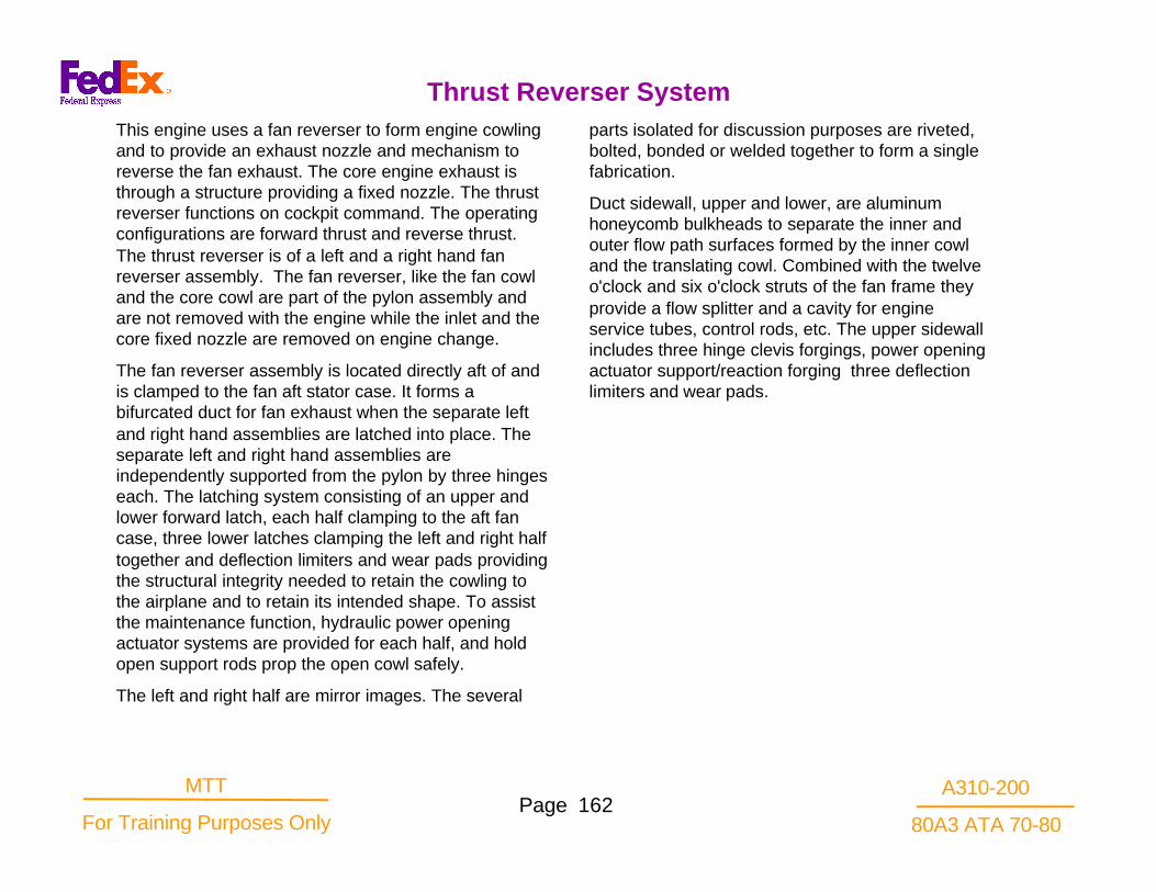
A310-200
80A3 ATA 70-80Page 162
MTT
For Training Purposes Only
This engine uses a fan reverser to form engine cowlingand to provide an exhaust nozzle and mechanism toreverse the fan exhaust. The core engine exhaust isthrough a structure providing a fixed nozzle. The thrustreverser functions on cockpit command. The operatingconfigurations are forward thrust and reverse thrust.The thrust reverser is of a left and a right hand fanreverser assembly. The fan reverser, like the fan cowland the core cowl are part of the pylon assembly andare not removed with the engine while the inlet and thecore fixed nozzle are removed on engine change.
The fan reverser assembly is located directly aft of andis clamped to the fan aft stator case. It forms abifurcated duct for fan exhaust when the separate leftand right hand assemblies are latched into place. Theseparate left and right hand assemblies areindependently supported from the pylon by three hingeseach. The latching system consisting of an upper andlower forward latch, each half clamping to the aft fancase, three lower latches clamping the left and right halftogether and deflection limiters and wear pads providingthe structural integrity needed to retain the cowling tothe airplane and to retain its intended shape. To assistthe maintenance function, hydraulic power openingactuator systems are provided for each half, and holdopen support rods prop the open cowl safely.
The left and right half are mirror images. The several
parts isolated for discussion purposes are riveted,bolted, bonded or welded together to form a singlefabrication.
Duct sidewall, upper and lower, are aluminumhoneycomb bulkheads to separate the inner andouter flow path surfaces formed by the inner cowland the translating cowl. Combined with the twelveo'clock and six o'clock struts of the fan frame theyprovide a flow splitter and a cavity for engineservice tubes, control rods, etc. The upper sidewallincludes three hinge clevis forgings, power openingactuator support/reaction forging three deflectionlimiters and wear pads.
Thrust Reverser System

A310-200
80A3 ATA 70-80Page 163
MTT
For Training Purposes Only
Thrust Reverser

A310-200
80A3 ATA 70-80Page 164
MTT
For Training Purposes Only
The redirection of fan discharge air through thedeflector vanes rather than through the fan exhaustnozzle results in an efficiency loss in the airflowutilization. The reverse thrust resulting from the samefan speed is approximately 40% of the thrust that isavailable in forward mode. Since increased fan speedto increase reverse thrust requires a commensurateincrease in core speed, and core thrust is notreversed", there is an optimum reverse fan/corespeed. Flight test indicates the maximum net reversethrust is obtained at approximately 95% N1 This is areverse thrust of approximately 9000 lbs. The weight ofthe two reverser halves is 1322 lbs. combined. It isbroken down as 1002 lbs for fixed structure, transcowl293lbs, and pylon interface of 27 lbs.
Thrust Reverser Assembly

A310-200
80A3 ATA 70-80Page 165
MTT
For Training Purposes Only
Thrust Reverser Assembly

A310-200
80A3 ATA 70-80Page 166
MTT
For Training Purposes Only
Each fan reverser half assembly is operated by a singlepneumatic motor, powered by the aircraft pneumaticsystem. The motor drives ballscrew actuators throughflexible shafts and gearboxes to translate and rotatereverser components to the desired position. Sources ofair supply are provided in airframe installations formaintenance functions. Appropriate interlocks andposition-indicator switches are incorporated in thesystem. The system is not designed for operation inflight.
Thrust Reverser Assembly

A310-200
80A3 ATA 70-80Page 167
MTT
For Training Purposes Only
Thrust Reverser System

A310-200
80A3 ATA 70-80Page 168
MTT
For Training Purposes Only
Deflector Vane Configuration
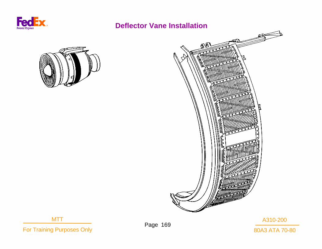
A310-200
80A3 ATA 70-80Page 169
MTT
For Training Purposes Only
Deflector Vane Installation

A310-200
80A3 ATA 70-80Page 170
MTT
For Training Purposes Only
Inner cowl is an aluminum acoustic honeycombbondment providing an aerodynamic inner flow surfacefor the fan duct and a core engine forward cowl. Thecowl is riveted to the duct sidewalls. On the forwardedge of the cowl a partial vee band flange engages agroove on the fan frame. A faying surface forengagement of the overlapped core engine cowl is onthe aft inner surface. Six hinge boxes for blocker doorlink assemblies are attached to each inner cowl. Airextraction ducts and vents penetrate the inner cowl forfan air pre-cooler, compartment cooling, low pressurerecoup venting. Zee rings riveted to the inner surfaceprovide additional stiffening to honeycomb.
Outer support assembly is a riveted and boltedframework of aluminum sheet and extrusions supportthe translating cowl and the vaned deflector assembly.It is riveted to the duct sidewalls. It is supported andstiffened by a forward latch ring assembly whichengages a Vee on the outer aft fan case and hookstwelve and six o'clock to the fan case. Tee slots andbeam deflectors, which are teflon lined, provideguideways and support to the translating cowl.Forward fairing panels: Three pieces, acousticallytreated, composite material, attached by screws.Provides outer flow path between the fan case and thetranslating cowl blocker doors.
Vaned deflectors are cast aluminum. The blank offpanels are aluminum. The panels are bolted to thesupport assembly to provide various optional patterns ofair reflection. The system panels, each half, are selectedbased upon engine position, inboard or outboard half,and for aerodynamic and braking effective panels areindividually replaceable except at the five deflectorbeams where it is necessary to loosen the adjacentpanel for access to hidden flat head bolts. Brackets areassembled onto the fixed structure to support twoballscrew actuators, and the center drive unit (CDU). TheCDU is also supported on the forward end by two axialpins of a bracket accepting radial and vertical loads.
Fan Reverser System

A310-200
80A3 ATA 70-80Page 171
MTT
For Training Purposes Only
Fan Reverser, Exploded - Left Side

A310-200
80A3 ATA 70-80Page 172
MTT
For Training Purposes Only
THIS PAGE INTENTIONALLY LEFT BLANK

A310-200
80A3 ATA 70-80Page 173
MTT
For Training Purposes Only
Fan Reverser, Exploded - Ride Side

A310-200
80A3 ATA 70-80Page 174
MTT
For Training Purposes Only
Secures the outer leading edge of the fan reverserhalves to the aft flange of the fan case and transmitsreverser loads into fan frame and not to hinges in pylonarea. This is a half Vee band type quick disconnectflange mounting ring. It is teflon coated. The top latch ofthe mounting ring is a hook that slips into a "U" boltbracket atop the fan stator case. The "U" bolt isadjustable to control upper latching force.
Lower Latches
Interconnect the fan reverser halves at the bottom mid-section. The latches are located within the area coveredby the access panel. Latch handle tension is adjustedby eccentric bushings position.
Access and Blow-out Door Assembly
A three piece design. The panel is hinged to the righthand half and fastened to the left hand half. Only thecenter section has blow-out function, it must open firstand close last. The aft section has vent port. Thebottom latch is a barrel nut that fits into a “claw” typeclevis bracket a the bottom of the fan case. The barrelnut is adjustable to control latching force.
The exposed aluminum surfaces are protected with anintumescent coating for fire protection.
Mounting Ring Latch Assembly

A310-200
80A3 ATA 70-80Page 175
MTT
For Training Purposes Only
Fan Reverse Latches

A310-200
80A3 ATA 70-80Page 176
MTT
For Training Purposes Only
A construction of composite material ofKevlar/Graphite/fiberglass facesheet with Nomex core.Hinges and pockets are bonded in. The structureprovides an outer flow path for the fan air, a smoothlow drag outer cowl, and a pocket to enclose thevaned deflector assembly in the stowed position.The transcowl is positioned by three ballscrewactuators whose rod end bearings are locked into castpockets by removable pins. The translation is guidedby teflon coated tee hinged rails engaging the Teeslots of the support assembly and five teflon coatedstrips sliding along the beam deflectors. Hinge clevisesprovide the forward pivot for the deployment of theblocker doors. In the stowed position a three piecebulb seal bolted to the transcowl at the forward edge ofthe blocker door support ring provides an aerodynamicseal of the deflector vane cavity. Attached to the outercowl structure at the leading edge are ten nylonbumpers to engage and stiffen at the support structureplus two bumpers, one at top, one at bottom, includingtwo captive nuts each for deactivation security of thetranscowl. Six composite material honeycomb Boundspanels are attached by screws to the inner flowpath ofeach transcowl.
Translating Cowl

A310-200
80A3 ATA 70-80Page 177
MTT
For Training Purposes Only
Fan Reverser, Exploded - Left Side

A310-200
80A3 ATA 70-80Page 178
MTT
For Training Purposes Only
The actuator is driven by a portable hydraulic pumpattached to a quick disconnect coupling at the lowerballscrew actuator of the transcowl deploy system.One actuator each reverser half permits it to beopened independently for access to the core engine.The actuators are mounted to the aircraft pylon andpush against the actuator mount forging on the ductsidewall. Safety requires the use of a hold open rodbefore getting under an open cowl half. The aft fayingsurface of the reverser cowl overlaps the core enginecowling, therefore, the reverser must be openedbefore the core cowl can be opened.
The actuator inlet fitting incorporates a restrictor as asafety device limiting the rate of closure. In the eventof a hydraulic line rupture, the restrictor will provideapproximately 15 seconds for personnel escape.A 25 micron filter at the input fitting protects therestrictor and actuator assembly from hydraulic fluidcontamination. A cooling jacket assures actuator aircooling from an external source. The quickdisconnect coupling includes a dust coverincorporating a fluid overflow container and a highpressure relief valve for the system set at 4350-4400psig.
Cowl Door Hydraulic Actuator

A310-200
80A3 ATA 70-80Page 179
MTT
For Training Purposes Only
Cowl Door Hydraulic Actuator

A310-200
80A3 ATA 70-80Page 180
MTT
For Training Purposes Only
Blocker doors are pivoted into the fan exhaust to blockthe normal flow path, requiring the fan air to exitthrough the vaned deflector assembly. A compositestructure of fiberglass face sheet, graphite/fiberglassback pan with aluminum hinge castings bonded intoplace. The blocker doors are hinged on their forwardedge to the translating cowl and bolted to the blockerlink arm at the link housing near the aft edge. Theblocker link acts as a radius rod controlling the rotationof the blocker door into the fan air as the trans cowl isdeployed. The blocker doors are radially loaded by a100 pound spring contained in the blocker link hingebox to avoid flutter when stowed. There are variouspatterns of blocker doors -standard, upper left andright, lower left and right. Six blocker doors arerequired each half.
Blocker Door

A310-200
80A3 ATA 70-80Page 181
MTT
For Training Purposes Only
Blocker Door
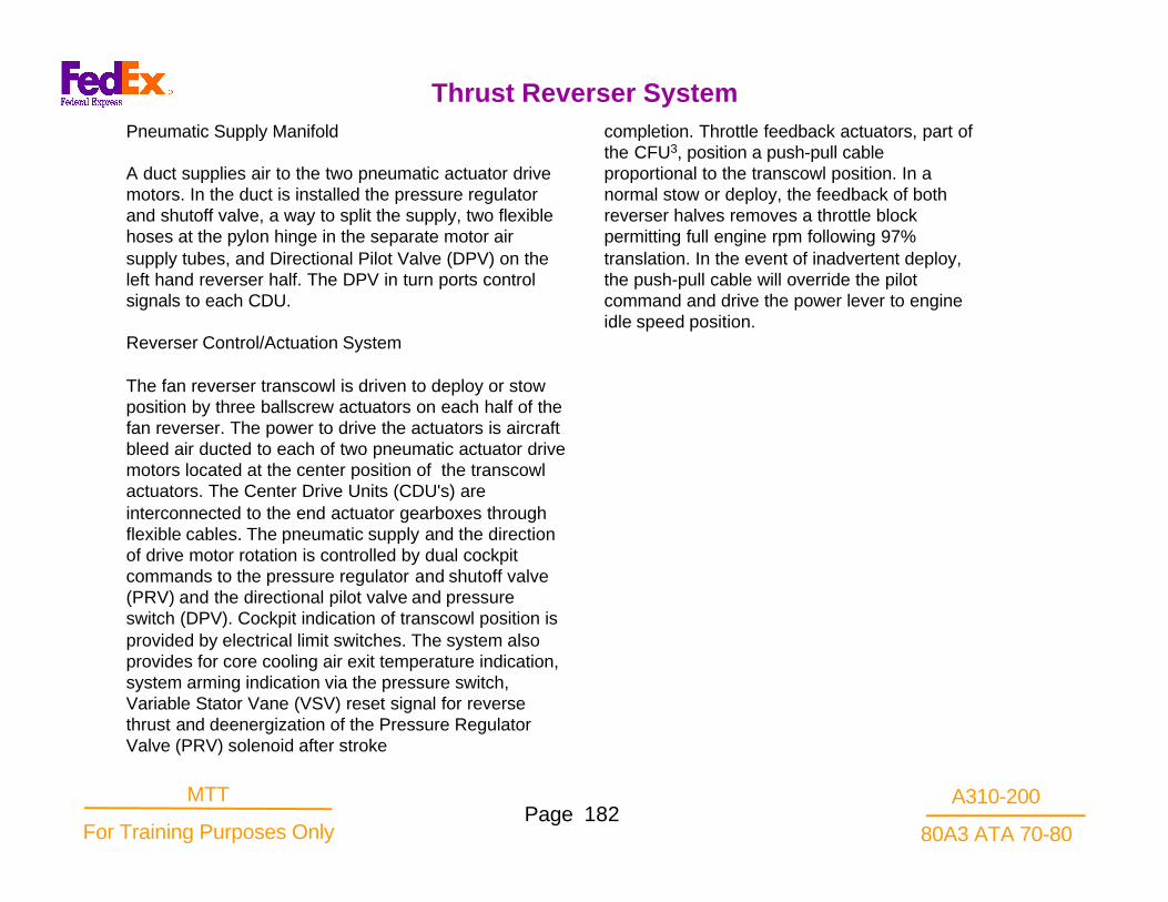
A310-200
80A3 ATA 70-80Page 182
MTT
For Training Purposes Only
Pneumatic Supply Manifold
A duct supplies air to the two pneumatic actuator drivemotors. In the duct is installed the pressure regulatorand shutoff valve, a way to split the supply, two flexiblehoses at the pylon hinge in the separate motor airsupply tubes, and Directional Pilot Valve (DPV) on theleft hand reverser half. The DPV in turn ports controlsignals to each CDU.
Reverser Control/Actuation System
The fan reverser transcowl is driven to deploy or stowposition by three ballscrew actuators on each half of thefan reverser. The power to drive the actuators is aircraftbleed air ducted to each of two pneumatic actuator drivemotors located at the center position of the transcowlactuators. The Center Drive Units (CDU's) areinterconnected to the end actuator gearboxes throughflexible cables. The pneumatic supply and the directionof drive motor rotation is controlled by dual cockpitcommands to the pressure regulator and shutoff valve(PRV) and the directional pilot valve and pressureswitch (DPV). Cockpit indication of transcowl position isprovided by electrical limit switches. The system alsoprovides for core cooling air exit temperature indication,system arming indication via the pressure switch,Variable Stator Vane (VSV) reset signal for reversethrust and deenergization of the Pressure RegulatorValve (PRV) solenoid after stroke
completion. Throttle feedback actuators, part ofthe CFU3, position a push-pull cableproportional to the transcowl position. In anormal stow or deploy, the feedback of bothreverser halves removes a throttle blockpermitting full engine rpm following 97%translation. In the event of inadvertent deploy,the push-pull cable will override the pilotcommand and drive the power lever to engineidle speed position.
Thrust Reverser System

A310-200
80A3 ATA 70-80Page 183
MTT
For Training Purposes Only
Thrust Reverser System

A310-200
80A3 ATA 70-80Page 184
MTT
For Training Purposes Only
A normally closed valve with a 28V DC solenoidoperated pilot. It is provided an opening electricalsignal from the cockpit pedestal switch when thereverse lever is positioned to the reverse thrustinterlock stop. It is installed on a standoff bracket onthe upper compressor case at approximately stage 3.The valve is made of steel.
In operation mode, ECS air supply flowing across thesolenoid valve pressurizes the opening actuatorcompressing the closing spring and overcoming theforce on the smaller closing actuator. Regulation ofdownstream pressure is accomplished through thereference regulator venting opening actuator pressureabove the reference set point of 70 psig. Inlet pressurechanges are reflected in opening actuator pressuresand downstream pressures are the result of themodulating poppet valve. Maximum downstreampressure will be limited by a relief valve which alsovents opening actuator pressures at a predeterminedvalue of 150 psig. Control orifices are placed in theservo line to reduce and dampen flow variations and toassist the relief valve regulation.
In normal deployment situations the ECS air supplypressure is not high enough to cause valve regulationto occur .In rejected takeoff condition however, theengine speed may develop enough 8th stage bleedpressure to drive the valve into the regulation mode
i.e. above the reference regulator venting point of70 psig. In this case the poppet will modulate tolimit the downstream pressure. The solenoid isautomatically deenergized when the commandedposition is attained. If an unstowed condition shoulddevelop while the command signal is still in stow,the solenoid would be energized. This will open thepoppet valve supplying regulated air to the centerdrive units to return the reverser to the stowposition.
Pressure Regulator and Shutoff Valve

A310-200
80A3 ATA 70-80Page 185
MTT
For Training Purposes Only
Pressure Regulator and Shutoff Valve

A310-200
80A3 ATA 70-80Page 186
MTT
For Training Purposes Only
This is a component providing two functions in onehousing. The pressure switch can illuminate a cockpitlight when the duct is pressurized confirming the armingof the thrust reverser system or the inadvertentpressurization due to a malfunction of the PressureRegulator valve. This signal could also be placed inparallel with the stow switches. The directional pilotvalve, when the solenoid is energized, will pressurizethe directional control valve actuator in the CDU's withair to cause deploy rotational direction to occur in thedrive motors. The component is installed on the lefthand reverser half adjacent to the upper angle gearboxand ballscrew. It is teed into the left hand actuator airsupply.
OPERATION: At the deploy command from the cockpitthe solenoid will be energized.This will allow air topressurize two tubes (flexible lines across the pylonarea) of approximately equal length, one to eachdirectional control valve of the center drive units. Whenthe throttle is returned to the forward thrust mode, thesolenoid will be deenergized, removing the ECS airfrom the directional control valve actuator. The CDUdirectional control valve will reverse the ECS air supplyflow direction through the gear motor at this command.
Directional Pilot Valve and Pressure Switch
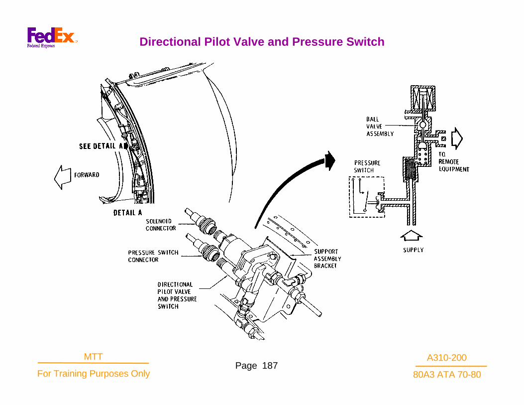
A310-200
80A3 ATA 70-80Page 187
MTT
For Training Purposes Only
Directional Pilot Valve and Pressure Switch

A310-200
80A3 ATA 70-80Page 188
MTT
For Training Purposes Only
Functions and Purposes.
Left hand and right hand units are required. They areinstalled at the 3 and 9 o’clock positions on the fanreverser. It is multi-function component.
Functions and purposes
An air motor and directional control valve.
A gearbox and two drive pads to drive flexible cablesto the reverser end actuators. There are two spare, redundant, drive pads which may be used for manualdeployment. By inverting the cover plate, which has asquare shank welded to it, the actuation system can be deactivated.
An internal stop rod which provides control feedbackand a load path to absorb the shock of stopping the translating cowl at deploy and stow.
An indicating system of electrical switches to identifyan unstowed and deployed condition.
A brake system to maintain the translating cowl in thestowed condition until commanded to deploy. A manual brake release is provided for maintenance purposes.
A rig position indicator and a sight peephole to verifyrig position enable easy location of the reverser actuation system rig base line.
Center Drive Unit (CDU)

A310-200
80A3 ATA 70-80Page 189
MTT
For Training Purposes Only
Drive Units

A310-200
80A3 ATA 70-80Page 190
MTT
For Training Purposes Only
The CDU's require an air supply connected to eitherend of an inlet tee fitting. The other end is normallycapped unless a ground air supply is to be provided foractivation without engine operation. It is a 1” fitting. Theground air supply is available from a tap on the starterair supply duct. Air pressure from the directional pilotvalve is applied to the CDU directional control valveactuator inlet port. Pressurization of the actuator willcompress the return spring, rotate the helix shaft. toturn the directional control valve to the deploy positionthus reversing the airflow direction through the airmotor, and release the cone shaped brake to permit airmotor rotation.
The air motor section consists of two-three lobedaluminum rotors synchronized by steel spur gears. Oneshaft drives the pinion bevel gear of the CDU ballscrewand is attached to the brake assembly. The other rotorshaft drives the feedback actuator assembly and thetwo auxiliary drive ports. (For a turbine reverser and alockout port covered by a plate and lockout pin).The hollow ballscrew shaft is rotated by the bevel ringgear translating the ball nut, the torque tube coveringthe ballscrew, and the translating cowl mid clevis pinnedto the actuator. The upper and lower ballscrewactuators are driven synchronously with the centeractuator through flexible cables installed to thefeedback actuator assembly splined drive shafts.
Near the end of the deploy stroke, the aft shoulderof the ball nut contacts the mushroom head of theinternal stop rod and begins the aftward translationof the stop rod, The stop rod is linked back to thedirectional control valve (DCV) which overrides thehigh speed deploy pressure command. As theactuator approaches its stop the DCV is closedthereby generating large air motor back pressuresand rapid deceleration. The same operation ofreducing the air supply inlet at full stow occurs,except there is a slot or bleed through the airexhaust port which maintains a pneumatic load onthe drive cables as long as pressure is available,The brake will hold the cable pre-load and preventrebound of the transcowl after striking the stops.Movement of the stop rod is limited by internal stopsin a housing forward of the bevel ring gear .Whenthe internal stops are contacted the translating cowlmovement will stop. The stop rod is a spring whichwill absorb the remaining stopping loads. The loadpath is through a face type roller thrust bearing onthe bevel ring gear into the motor/actuator mountingflange against the reverser fixed structure.
During the short translation of the stop rod, a clevisconnection to a cam shaft link arm operates theposition indicating switches. In stow the stop rod iscompressed positioning the cam to deactivate theswitches. As translation begins, initial movement
Thrust Reverser Actuation System

A310-200
80A3 ATA 70-80Page 191
MTT
For Training Purposes Only
Center Drive Unit (CDU)

A310-200
80A3 ATA 70-80Page 192
MTT
For Training Purposes Only
"makes" the unstow indicator light circuit. Near the endof stroke, contact of the stop rod mushroom endmoves the stop rod and makes the green "reversethrust" light and opens the unstow light circuit. Theunstow indicator switch will also energize the PressureRegulator and Shutoff Valve solenoid when that circuitis "made" by a failure resulting in a deploy movementof the translating cowl or actuator. The switches areline replaceable without rigging. All switches are in theone housing which is replaced as a unit.
Upon deployment, a linear actuator will retract into thefeedback assembly housing pulling on a flexible cableof the throttle interlock system. At the required numberof turns of the CDU, the feedback actuator will haveremoved the aircraft throttle block. The turns of theCDU are directly proportional to the transcowl position.The actuator rod contains two rig reference linesrepresenting the min.-max, tolerance for rigging. Thehousing containing the feedback actuator rod permitsthe rod to be reversed. This reversal converts the CDUfrom a right hand to a left hand unit. It must bereworked at the shop level. The gear shafts whichdevelop the reversal of the feedback direction alsoprovides the output 12 point spline drive sockets forthe end actuator flexible cables.
Thrust Reverser Actuation System

A310-200
80A3 ATA 70-80Page 193
MTT
For Training Purposes Only
Center Drive Unit (CDU)

A310-200
80A3 ATA 70-80Page 194
MTT
For Training Purposes Only
THIS PAGE INTENTIONALLY LEFT BLANK

A310-200
80A3 ATA 70-80Page 195
MTT
For Training Purposes Only
Thrust Reverser Actuation System

A310-200
80A3 ATA 70-80Page 196
MTT
For Training Purposes Only
A gearbox is attached to the upper and lower ballscrewof each fan reverser half. They are grease-packed, zerobevel gearboxes with a speed reduction ratio of 3:1.The gearboxes incorporate two square input drives anda splined output for the ballscrew connection. Thesecond square drive on the opposite end of the inputshaft is capped; however, this connection may be usedto lock the actuator or for rigging purposes. Thegearbox is attached to the reverser fixed structure by agimbal mount. The ballscrew rod end is pinned to theclevis.
Angle Gearboxes

A310-200
80A3 ATA 70-80Page 197
MTT
For Training Purposes Only
Ballscrew Angle Gearbox

A310-200
80A3 ATA 70-80Page 198
MTT
For Training Purposes Only
Each ballscrew is spline coupled to its angle gearbox,clamped by a captive threaded nut which is locked bya splined limit stop collar. The ballscrew is rotated bythe gearbox, and this action translates the ball nut. Theball nut is restrained from rotation by the torque tubehousing and the torsion arm engaging a pocket of thetranscowl clevis at the rod end bearing end. Thedeployed length is determined by a dog type stopcollar pinned to the aft end of the ballscrew. Thedeployed limit is reached when the ball nut strikes thestop collar. The ballscrew stroke is adjustable by thecaptive nut of the gearbox within a narrow range. Theactuator length is adjustable by the rod end bearingthreaded into the aft end. The ball nut is greaselubricated.
Ballscrew Actuator

A310-200
80A3 ATA 70-80Page 199
MTT
For Training Purposes Only
Thrust Reverser Ballscrew Actuator
ADJUSTABLEON OLD
NOTADJUSTABLEON NEW
ADJUST COWLCAP

A310-200
80A3 ATA 70-80Page 200
MTT
For Training Purposes Only
There are four flex cables (two different lengths)interconnecting the drive ports of the CFU's with theend angle gearboxes. The inner member turns withina casing of corrosion resistant steel lined with Teflonand lubricated with grease. The inner member core isstranded music wire. It has a twelve tooth spline forrigging engagement at the CFU end while a .2 inchsquare end engages the angle gearbox.
Flexible Drive Cables

A310-200
80A3 ATA 70-80Page 201
MTT
For Training Purposes Only
Fan Reverser Flexible Shafts

A310-200
80A3 ATA 70-80Page 202
MTT
For Training Purposes Only
A switch assembly is installed onto each of the CDU's.The assembly contains a deploy and stow switch.They are each of the double pole double throw type.The switches are operated by motion of the stop rodmechanism. One switch changes contact within 0.3inch of full deploy. The other switch changes within 0.2inch of full stow. A single connector is provided forharness attachment to both switches.
Position Indicator Switches

A310-200
80A3 ATA 70-80Page 203
MTT
For Training Purposes Only
Deploy/Stow Limit Switch

A310-200
80A3 ATA 70-80Page 204
MTT
For Training Purposes Only
Deploy Stroke

A310-200
80A3 ATA 70-80Page 205
MTT
For Training Purposes Only
Stow Stroke

A310-200
80A3 ATA 70-80Page 206
MTT
For Training Purposes Only
Page 5 Alternate--from AMM