air
62
PREFACE Practical training is an important constituent of any curriculum and Bachelor of Technology is no exception to this general rule. Practical training helps the student in getting acquainted with the manner in which his knowledge is being practically used outside the institution and this is normally different from what he has learned in the books. As one switches from the process of learning to that of implementation of his concepts, he finds an abrupt change. This is exactly why summer training session during the B.Tech. curriculum becomes all the more important. Summer training is prescribed for the student of Technical Colleges as a part of the four year degree course of engineering by the AICTE. We are required to undergo summer training for a period of 30 days after the completion of the 3rd year. There are various technological advances in the field of electronics and communication that the world at large is witnessing. The vaccum tubes have been replaced by small ICs and the transmission medium of wires and cables which have high dielectric and tangent losses has been replaced by negligible lossy medium like the optical fibers. The wired communication has been replaced by wireless communication and even in wireless communication the analog means of communication is getting replaced by digital means of communication for higher accuracy and bit transfer rate and for less susceptibility towards noise. This training report describes in detail the training after the 3rd year session, which I completed successfully at the All India Radio, Jaipur which is the oldest government organization in the field of media and broadcasting. This report also gives the information about the organization and its working along with the vocational training undertaken during the training period. All India Radio provided me an exposure in the field of communication for the first time. It was an honor for me to meet AIR professionals. They taught me about how the organization works and strives to reach the maximum of the population, through its various intricate and complicated technologies of communication. We were made aware of the technologies which are used in AIR for the purpose of broadcasting and communication and of the importance of radio in today‟s world which has still hooked the country into one unit in spite of the popularity of television and internet among the people.
-
Upload
debojyoti-majumdar -
Category
Documents
-
view
119 -
download
2
Transcript of air

PREFACE
Practical training is an important constituent of any curriculum and Bachelor of Technology
is no exception to this general rule. Practical training helps the student in getting acquainted
with the manner in which his knowledge is being practically used outside the institution and
this is normally different from what he has learned in the books. As one switches from the
process of learning to that of implementation of his concepts, he finds an abrupt change.
This is exactly why summer training session during the B.Tech. curriculum becomes
all the more important. Summer training is prescribed for the student of Technical Colleges
as a part of the four year degree course of engineering by the AICTE. We are required to
undergo summer training for a period of 30 days after the completion of the 3rd year.
There are various technological advances in the field of electronics and
communication that the world at large is witnessing. The vaccum tubes have been replaced
by small ICs and the transmission medium of wires and cables which have high dielectric and
tangent losses has been replaced by negligible lossy medium like the optical fibers. The wired
communication has been replaced by wireless communication and even in wireless
communication the analog means of communication is getting replaced by digital means of
communication for higher accuracy and bit transfer rate and for less susceptibility towards
noise.
This training report describes in detail the training after the 3rd year
session, which I completed successfully at the All India Radio, Jaipur which is the oldest
government organization in the field of media and broadcasting. This report also gives the
information about the organization and its working along with the vocational training
undertaken during the training period.
All India Radio provided me an exposure in the field of communication for
the first time. It was an honor for me to meet AIR professionals. They taught me about how
the organization works and strives to reach the maximum of the population, through its
various intricate and complicated technologies of communication. We were made aware of
the technologies which are used in AIR for the purpose of broadcasting and communication
and of the importance of radio in today‟s world which has still hooked the country into one
unit in spite of the popularity of television and internet among the people.

ACKNOWLEDGEMENT
Exchange of ideas generates the new objects to work in a better way. This report is based on
the ideas exchanged among the students and the trainers at AIR, Jaipur and the study
materials provided by the AIR professionals.
I owe my sincere thanks to Mr. Banerjee, Mr. R.K. Chaturvedi, Mr. Manohar Lal Sharma,
trainers at All India Radio, Jaipur for providing me their continuous motivation for the
project and whole hearted support in this endeavour, which proved vital for the successful
completion of summer training ’10. Without their expert help and guidance it was difficult to
develop this report.
I would like to thank Mr. H.K.Patsaria (Assistant Engineer) and Mr. ( HR Manager) for
accepting my application of summer internship in their esteem organization and also
considering my name eligible for the merit list.
I would also like to express my gratitude to Mr. Sudhanshu Mathur (HOD- ECE) and other
faculties whose kind inspiration and invaluable guidance encouraged me from time to time
and helped me in the successful completion of the summer practical training report. I am also
thankful to all my colleagues for their co-operation and support.
Debojyoti Majumdar
(Vll Semester, E.C.E)

COMPANY PROFLE
All India Radio‟s history dates back to the early 1920s when radio broadcasting started in
India. The first programme was broadcasted in 1923 by the Radio Club of Bombay. This was
followed by setting up of Broadcasting Services in 1927 with two privately owned
transmitters at Bombay and Calcutta. The British Government then took over the radio
transmission in India and under its banner it came to be known as The Indian Broadcasting
Service. It was all changed to All India Radio (AIR) in 1936 with clear objective to inform,
educate and entertain the masses which after independence came to be known as Akashvani
from 1957.
There are at present 231 radio stations in the country. Each of these radio stations functions
as the sub-ordinate office of All India Radio. The main function of these centres is to transmit
the programmes produced at nearby local CBS or other studios and also from New Delhi
studio.
Since its inception All India Radio has become one of the largest broadcasting network in the
world serving the ever increasing population of India. At the time of independence there were
only 6 radio stations and 18 transmitters, which covered 11% population and 2.5% of total
land area of the country. Till December,2007 the network comprises of 231 radio stations and
373 transmitters which provide radio coverage to 99.14% of the population and reaches
91.79% area of the country, a total of 384 channels and transmits in 24 different languages
and dialects. In spite of recent penetration by other media such as Cable TV, AIR remains the
most common means of gaining access to information and entertainment, as the radio
receivers are relatively cheap and affordable.
In Rajasthan itself there are 23 transmitters and 5 CBS radio stations and 17 non-CBS
stations serving the population of the state of Rajasthan. The main high power transmitter of
50KW is stationed at Ajmer because Ajmer is located at the centre of Rajasthan, from where
the programmes are broadcasted to all other parts of Rajasthan. The Jaipur CBS station has
got its transmitter of 2KW stationed at Vaishali Nagar, Jaipur, which is used to transmit
programmes from the Jaipur CBS station to the Ajmer CBS station so that the programme
can be transmitted to all other parts of Rajasthan. For FM transmission, there are 21 FM
transmitters of 1KW in Jaipur situated at a distance of 40km from each other.
ORGANISATIONAL SET UP
The Directorate General, All India Radio functions under the Prasar Bharati. The Prasar
Bharati Board functions at the apex level ensuring formulation and implementation of the
policies of the organisation and fulfillment of the mandate in terms of the Prasar Bharati. Act,
1990. The Executive Member functions as a Chief Executive Officer (CEO) of the
Corporation subject to the control and supervision of the Board. The CEO, the Member
(Finance) and the Member (Personnel) perform their functions from Prasar Bharati
headquarters at 2nd Floor, PTI Building - Parliament Street, New Delhi-110001.
All important policy matters relating to Finance, Administration and Personnel are submitted
to CEO and the Board through the Member (Finance) and Member (Personnel) as required,
for the purpose of advice, implementation of proposals and decisions thereon. Officers from
different streams working in the Prasar Bharati Secretariat assist the CEO, Member (Finance)
and Member (Personnel) in integrating action, operations, plans and policy implementation as
well as to look after the budget, accounts and general financial matters of the Corporation.

Prasar Bharati also has a unified vigilance set up at the headquarters, headed by a Chief
Vigilance Officer.
The Director General of All India Radio is headed by the Director General. He functions in
close association with the Member (Finance) and Member (Personnel) and the CEO in
carrying out the day to day affairs of AIR. In AIR there are broadly five different Wings
responsible for distinct activities viz, Programme, Engineering, Administration, Finance and
News.
PROGRAMME WING
The Director General is assisted by Deputy Directors General in the Headquarters and
Deputy Directors General in the regions for a better supervision of the stations. The
Headquarters of the Regional DDGs are situated at Kolkata (ER) Mumbai and Ahmedabad
(WR), Lucknow (CR-I), Bhopal (CR-II), Guwahati (NER), Chennai SR-I), Bangaluru (SR-
II), Delhi (NR-I) and Chandigarh (NR-II).
ENGINEERING WING
In respect of technical matters of All India Radio, The Director General is assisted by the
Engineer-in-Chief and Chief Engineers posted in the headquarters and the zonal Chief
Engineers. In addition, there is a Planning and Development Unit in the Headquarters to
assist the Director General in respect of Development Plan Scheme of All India Radio. In
respect of Civil Construction activities, the Director General is assisted by the Civil
Construction Wing, which is headed by a Chief Engineer. CCW also caters to the needs of
Doordarshan.
ADMINISTRATIVE WING
A Dy. Director General (Administration) assists the Director General on all matters of
administration while Dy. Director General (Programme) assists DG in administration of
Programme personnel. A Director looks after the Engineering Administration of All India
Radio, while another Director (Admin. & Finance) assists DG in matters of administration
and finance.
SECURITY WING
The Director General is assisted by a Deputy Director General (Security), Asstt. Director
General (Security) and a Dy. Director (Security) on matters connected with the security and
safety of AIR installations, transmitters, studios, offices etc.
AUDIENCE RESEARCH WING
There is a Director, Audience Research to assist the Director General in carrying out surveys
of audience research on the programmes broadcast by various station of All India Radio.

ACTIVITIES OF SUBORDINATE OFFICES OF AIR
There are a number of subordinate offices of All India Radio performing distinct functions.
Broad activities, in brief, are given below.
NEWS SERVICES DIVISION
News Services Division works round the clock and broadcasts over 500 news bulletins both
in the home and external services. The bulletins are in Indian and Foreign languages. It is
headed by Director General, News Service. There are 44 regional News Units. The bulletins
vary from region to region according to news interest.
EXTERNAL SERVICE DIVISION
As a 'Voice of the Nation', External Services Division of All India Radio has been India's
"Authentic Window to the World". With growing importance of India in the world, an
increasingly important role is envisaged for External Broadcast for times to come. External
Services Division of All India Radio broadcasts in 16 foreign and 11 Indian languages for
approximately 72 hours in a day covering more than 100 countries.
TRANSCRIPTION & PROGRAMME EXCHANGE SERVICE
This service looks after exchange of programmes among the stations, building and
maintenance of sound archives and commercial release of prestigious recordings of music
maestros.
RESEARCH DEPARTMENT
The functions of the Research Department include Research and Development of equipment
required by AIR and Doordarshan, investigation and studies relating to AIR and
Doordarshan, development of prototype models of R&D equipment for limited use, field
trials in the network of AIR and Doordarshan.
CENTRAL STORE OFFICE
The Central Store Office located at New Delhi performs functions relating to procurement,
stocking and distribution of engineering stores required for the maintenance of technical
equipment at All India Radio Stations.
STAFF TRAINING INSTITUTE (PROGRAMME)
The Staff Training Institute (Programme) started with Directorate since 1948 has presently
two main branches functioning from Kingsway Camp, Delhi and Bhubaneshwar. It imparts
in-service training to programme personnel and administrative staff and induction course for
the newly recruited staff and short duration refresher courses. It conducts examinations for
administrative staff. In addition, at present five Regional Training Institutes at Hyderabad,
Shillong, Lucknow, Ahmedabad and Thiruvananthapuram are working.

1 INTRODUCTION
Communication is a term which means a process of transferring information from one place
to the other. That place can be anywhere within the earth. But the earth atmosphere and the
other surrounding objects are a lossy medium which absorbs the signals that is being
transmitted with the help of the transmitter. As a result of this the signal that is received by
the receiver is of very weak strength. Further more noise is also added in a considerable
amount to the signal. In order to reduce the addition of noise to the signal and the signal
could be transmitted to a longer distance from antenna of adequate width various modulation
schemes have been employed which are discussed below.
1.1 Modulation
Modulation is a process of superimposing information on a carrier by varying one of its
parameters (amplitude, frequency or phase).
1.2 Need for Modulation
Modulating the signal over high frequencies can reduce antenna size.
To differentiate among transmissions (stations).
Maximum to minimum frequency ratio can be reduced to minimum by modulating the
signal over high frequency.
1.3 Types of Modulation
In general there are two types of modulation:
a) Amplitude Modulation
b) Angle Modulation
1.31 Amplitude Modulation
If the amplitude of the carrier is varied in accordance with the amplitude of the baseband
signal, it is called amplitude modulation. This modulation is shown in figure 1.1. We can see
this on the screen of oscilloscope.
1.32 Spectrum of AM Signal
The spectrum of AM signal is shown in figure 1.2. If fm = modulating frequency fc =
Carrier frequency. The Spectrum of AM signal will be as below:
Power in the carrier,
Pc = (Ac / 2 ½)
2 = (Ac)
2 / 2
Power in sideband,
Plsb = Pusb = (ma2 Ac
2)/8
Power in upper sideband (Pusb) = Power in lower sideband (Plsb)
Hence total power, Pt = Pc + Pusb + Plsb = Ac2 {1+ (ma
2)/2} / 2 = Pc {1+ (ma
2)/2}
Where,
Ac = Amplitude of the carrier
Am = Amplitude of the modulating signal
ma = Modulation index = Am/Ac
Bandwidth,
BW = (fc + fm) – (fc + fm) = 2fm

1.33 Angle Modulation
Variation of the angle of carrier signal with time results in angle modulation. It is of two
types
a) Frequency Modulation
b) Phase Modulation
1.33.1 Frequency Modulation
If the frequency of the carrier is varied in accordance with the amplitude of the modulating
signal (information), it is called frequency modulation. This has been shown in figure given
below.
1.33.2 Spectrum of FM signal with sinusoidal modulation
A frequency modulated signal has a large number of frequency components even when the
modulating signal is a single frequency signal. The adjacent frequency components are
spaced just fm apart. These components lie on both sides of the carrier and are symmetrically
placed about it. The amplitudes of the corresponding component are equal. The components,
with frequencies (fc + fm) and (fc - fm) are called the first order side bands. The amplitude of
each of the first order side bands is AJ1 (mf). The components with frequencies (fc - nfm) and
(fc - nfm), where n is an integer, are called the nth order side bands. The amplitude of carrier is
AJ0 (mf). The relative amplitudes of various side bands, therefore, depend upon the index of
modulation alone, the amplitude of a particular side bands being equal to the Bessel function
of the corresponding order. The spectrum is shown in figure given below.
From the above we find that the process of frequency modulation results in a reduction of
carrier amplitude and generation of an infinite number of side bands. Generally, a limited
number of side bands closer to the carrier frequency will have significant amplitudes.
Power
Pc = Ac2/2 = Power of the unmodulated carrier
This holds true for any type of modulating signal and for any value of modulation index.
Where, Ac = Amplitude of the carrier
Am = Amplitude of the modulating signal
mf = df / fm = Modulation index
df = Frequency deviation
fm = Frequency of the modulating signal
Bandwidth of FM signal
Band width can be defined as that frequency range which accommodates the carrier and the
closest side bands contributing at least 98% of the total signal power. (Carson rule).
BW = 2(mf + 1) fm = 2(mf fm + fm) = 2(df + fm)
1.33.3 Phase Modulation
If the Phase of the carrier is varied in accordance with the amplitude of the modulating signal
(information), it is called phase modulation. This modulation has got minimum use.

2. MW TRANSMITTER
All India Radio uses various MW transmitters in its network. They are from 1 kW to 500 kW
power. Various power and make of transmitters used are:
1. 1 kW MW Transmitter – BEL, Harris, BE
2. 10 kW/20 kW Transmitter – BEL, Harris
3. 100/200 kW BEL – HMB 140.
4. 100 kW – Thales (Fully Solid state)
5. 200 kW/300 kW – Thales (Fully Solid State)
6. 300 kW – BBC – Tube Version.
7. 500 kW BBC/Russian Transmitter.
2.1 10 KW MW TRANSMITTER (HMB 163)
2.11 SALIENT FEATURES
Identical type of valves both for PA and Modulators.
Except in the final stage, all other stages are solid state operated.
Valves are ceramic metal tetrode permits full range operation upto 110 MHz.
PA is in Class C amplitude modulated which is one of the oldest and yet most popular
modulation technique used in India and elsewhere in the world.
Microprocessor controlled system with self diagnostic facility.
Efficiency is better than 50%.
A compact and modular system with everything in a single cabinet.
2.12 TECHNICAL SPECIFICATION
1. Emission : Double side band broadcasting on MW.
2. Rated Carrier output kW : 10 kW however it can go upto 15 kW (max.)
3. Output Impedance : 230 ohm for open line and 50 ohm for cable
feed type.
4. AF response : -1.5 dB
5. Distortion : Less than 4%
6. Noise Level : -60 dB
7. Audio Input Level : 0 dbm for 100% modulation
8. Audio Input impedance : 600 ohm bal
9. Power consumption : 20 KVA on carrier
22 KVA on 40% modulation
30 KVA on 100% modulation
2.2 100 KW HMB 140 MEDIUM WAVE TRANSMITTER
AIR has 52 transmitters of this type and is the back bone of MW service. So let us discuss
this transmitter in detail.

RF circuits consists of a crystal oscillator, transistor power amplifier, RF. Driver and Power
Amplifier of 100 kW HMB 140 MW transmitter are shown in Fig. 7.
Block Diagram of RF Chain (HMB-140)
2.21 CRYSTAL OSCILLATOR
To oscillate at a consistent frequency, the crystal is kept in a oven. The temperature of the
oven is maintained between 68 to 72o C and the corresponding indication is available in the
meter panel. Crystal oven is heated by + 12 V. One crystal oscillator with a stand by has
been provided. It gives an output of 5 V square wave which is required to drive the
Transistor Power Amplifier. The crystal oscillator works between 3 MHz and 6 MHz for
different carrier frequencies. Different capacitors are used to select different frequency
ranges. In addition, variable capacitor is used for varying the frequency of the crystal within
a few cycles. The oscillator frequency is divided by 2, 4, or 8 which is selected by jumpering
the appropriate terminals. The oscillator Unit gives 3 outputs, one each for RF output, RF
Monitoring and RF output indication.
2.22 TRANSISTOR POWER AMPLIFIER
Oscillator output is fed to the transistor Power amplifier (TRPA). It gives an output of 12
Watt across 75 ohms. It works on + 20 V DC, derived from a separate rectifier and regulator.
For different operating frequencies, different output filters are selected. (Low Pass Filter).
2.23 RF DRIVER
A 4-1000 A tetrode is used as a driver which operates under class AB condition, without
drawing any grid current. About 7 to 10 Watts, of power is fed to the grid of the driver
through a 75 : 800 ohms RF Transformer, which provides proper impedance matching to the
TRPA output and also provides the necessary grid voltage swing to the driver tube.
Various Pin Voltages
The cathode of the driver : - 600 V
Control grid : - 650 V
Screen grid : + 100 V
Plate Voltage : + 1900 V
Because the cathode is at -600 V, the effective grid to cathode bias voltage (fixed) is -50V
and the effective plate voltage is 2500 V. The driver develops a peak grid voltage of 800 to
900 V at the grid of PA and PA grid current of about 0.3 A to 0.4 Amps. The required wave
form for operating the PA as class -D operation is also developed at the output of the driver.
2.24 RF POWER AMPLIFIER

CQK - 50, condensed vapour cooled tetrode valve is used as a PA stage. High level anode
modulation is used, using a class B Modulator stage. The screen of the PA tube is also
modulated by a separate tap on modulation transformer. Plate load impedance of the PA
stage is about 750 ohms and the output impedance is 120 ohms, and it is matched by L-C
components. 11 kV DC, the HT voltage is connected to the plate of the PA valves through
the secondary of the modulation transformer and RF chokes : hence the AF signal is super
imposed on the DC for the PA plate.
2.25 PA OUTPUT CIRCUIT
PA Output Circuit (HMB-140)
The L-C combination of the output circuit provides the following :
1. Proper load impedance.
2. Matches the plate impedance of 750 ohms to the feeder impedance of 120 ohms/ 230
ohms at the operating frequency.
3. Filters all the 2nd and 3rd harmonic before the feeder.
2.26 AF STAGE
AF Stage (HMB-140)
The AF stage supply the audio power required to amplitude modulate the final RF stage. The
output of the AF stage is superimposed upon the DC voltage to the RF PA tube via
modulation transformer. An Auxiliary winding in the modulation transformer, provides the
AF voltage necessary to modulate the screen of the final stage. The modulator stage consists
of two CQK-25 ceramic tetrode valves working in push pull class B configuration. The drive
stages up to the grid of the modulator are fully transistorized.
2.26.1 HIGH PASS FILTER

The audio input from the speech rack is fed to active High Pass Filter. It cuts off all
frequencies below 60 Hz. This also has the audio attenuator and audio muting relay.
2.26.2 AF PRE-AMPLIFIER
The output of the High Pass Filter is fed to the AF Pre-amplifier, one for each balanced audio
line. Signal from the negative feed back network from the secondary of the modulation
transformer and the signals from the compensator also are fed to this unit.
2.26.3 AF PRE-CORRECTOR
This card corrects the audio for the non-linearity of modulator tubes. It uses an op-amp and
switching circuits which will distort the audio for different audio levels, opposite to that of
tube distortion.
1.26.4 AF DRIVER
2 AF drivers are used to drive the two modulator valves. The driver provides the necessary
DC Bias voltage and also AF signal sufficient to modulate 100%. The output of AF driver
stage is formed by four transistor in series as it works with a high voltage of about -400 V.
the transistors are protected with diodes and Zener diodes against high voltages that may
result due to internal tube flashovers. There is a potentiometer by which any clipping can be
set such that the maximum modulation factor will not exceeded.
2.26.5 AF FINAL STAGE
AF final stage is equipped with two ceramic tetrodes CQK-25. Filament current of this tube
is about 210 Amps. at 10V. They are working in fresh pull class „B‟ mode, through
modulation transformer.
A varistor at the screen or spark gaps across the grid are to prevent over voltages. As the
modulator valve is condensed vapour cooled tetrodes, deionised water is used for cooling.
The valve required about 11.5 litres/min. of water. Two water flow switches WF1 and WF2
in the water lines of each of the valves protect against low or no water flow. Thermostats
WT1 and WT2 in each water line provide protection against excessive water temp. by
tripping the transmitter up to stand-by if the temperature of the water exceeds 70o C.
Special high power varistor is provided across the secondary winding of the modulation
transformer to prevent transformer over voltages.

Power Supply in 100 kW HMB 140 MW Transmitter
1. HT -11 kV PA & Modulator : thyristor controlled for smooth variation of HT
2. 800 V Power Supply : Screen voltage to PA valve.
3. 1070 V : Screen voltage to modulate valve.
4. 1900 V : Plate voltage to RF Driver
5. - 650 V : (i) Grid Bias to PA Modulator & RF
Driver
(ii) A tap on -650 V provides -600 V supply to the
cathode of RF Driver
(iii) -100 V for the screen of RF Driver.
6. Thycon Unit : + 12 V DC and - 12 V DC
7. Audio Unit : + 24 V and + 10V.
8. Reflectometer : + 15 V & - 15 V
9. Control Circuits :
VDDB + 15 V - Logic circuits.
VDDC + 12 V - Relays
VDDD + 15 V for indication lamps.
VDDE - 15 V - Comparator.
10. Main supply to transmitter 415 V. 3 Phase 50 Hertz.
Earthing switch operated by a handle from the front of the rack has been provided in the filter
tank. The main HT terminal and also the live ends of the filter condensers C201 to C 210
have been brought to the earthing switch. In addition all the MT voltage (- 650, 800, 1070,
1900) are also brought to the earthing switch. The 11 kV point is discharged initially through
a resistor R - 543 before it is grounded. The earthing switch is interlocked to the main
transmitter by micro switches S 302, S 303 and S 304. In addition, a key interlock system is
provided to prevent accidental contact with high voltages.
2.27 CONTROL AND INTERLOCK SYSTEMS IN TRANSMITTER
Control and interlocking circuits of the transmitter are to perform four major functions :-
1. Ensure correct switching sequence.
2. Safety of the equipment.
3. Safety of the operating personnel.
4. Indication of the status of the transmitter.
In the following paragraph the details regarding the above aspects are dealt briefly :
1. Switching Sequence of Transmitter
a) Ventilation.
b) Filament
c) Grid Bias/Medium Tension
d) High Tension.
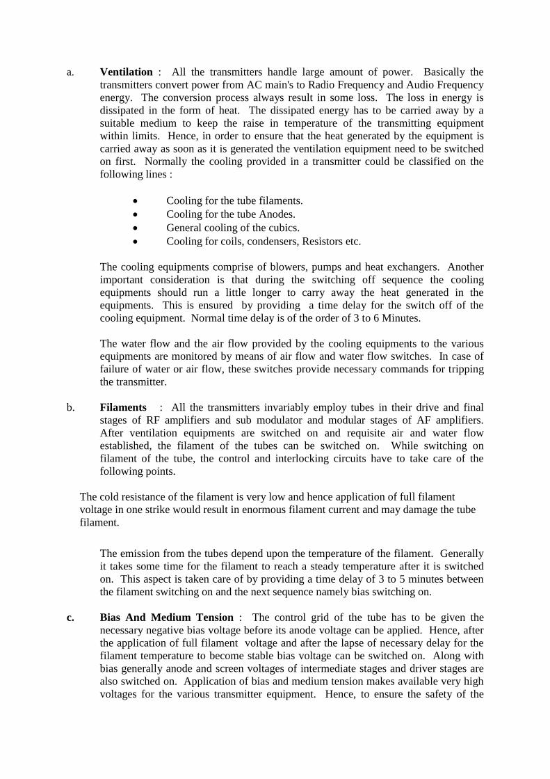
a. Ventilation : All the transmitters handle large amount of power. Basically the
transmitters convert power from AC main's to Radio Frequency and Audio Frequency
energy. The conversion process always result in some loss. The loss in energy is
dissipated in the form of heat. The dissipated energy has to be carried away by a
suitable medium to keep the raise in temperature of the transmitting equipment
within limits. Hence, in order to ensure that the heat generated by the equipment is
carried away as soon as it is generated the ventilation equipment need to be switched
on first. Normally the cooling provided in a transmitter could be classified on the
following lines :
Cooling for the tube filaments.
Cooling for the tube Anodes.
General cooling of the cubics.
Cooling for coils, condensers, Resistors etc.
The cooling equipments comprise of blowers, pumps and heat exchangers. Another
important consideration is that during the switching off sequence the cooling
equipments should run a little longer to carry away the heat generated in the
equipments. This is ensured by providing a time delay for the switch off of the
cooling equipment. Normal time delay is of the order of 3 to 6 Minutes.
The water flow and the air flow provided by the cooling equipments to the various
equipments are monitored by means of air flow and water flow switches. In case of
failure of water or air flow, these switches provide necessary commands for tripping
the transmitter.
b. Filaments : All the transmitters invariably employ tubes in their drive and final
stages of RF amplifiers and sub modulator and modular stages of AF amplifiers.
After ventilation equipments are switched on and requisite air and water flow
established, the filament of the tubes can be switched on. While switching on
filament of the tube, the control and interlocking circuits have to take care of the
following points.
The cold resistance of the filament is very low and hence application of full filament
voltage in one strike would result in enormous filament current and may damage the tube
filament.
The emission from the tubes depend upon the temperature of the filament. Generally
it takes some time for the filament to reach a steady temperature after it is switched
on. This aspect is taken care of by providing a time delay of 3 to 5 minutes between
the filament switching on and the next sequence namely bias switching on.
c. Bias And Medium Tension : The control grid of the tube has to be given the
necessary negative bias voltage before its anode voltage can be applied. Hence, after
the application of full filament voltage and after the lapse of necessary delay for the
filament temperature to become stable bias voltage can be switched on. Along with
bias generally anode and screen voltages of intermediate stages and driver stages are
also switched on. Application of bias and medium tension makes available very high
voltages for the various transmitter equipment. Hence, to ensure the safety of the
personnel various interlocks and safety are checked by control circuit before putting
on MT.
2.28 CONNECTION OF LOAD (ANTENNA/DUMMY LOAD)
After the application of ventilation, filament and bias the anode voltage can be switched
on. But before the anode voltage can be increased the interlocking circuit is to ensure that
the load of the transmitter namely antenna or dummy load is connected to the transmitter.
Application of Screen Voltage : In the case of tetrode tubes, the screen voltage to
the tube should not be applied before the application of anode voltage to keep the
screen current low. This is taken care of by an interlocking provision that the screen
voltage is applied only after the anode voltage reach a certain pre-determined value
well above the normal screen voltage.
Release of Audio frequency : The application of AF signal to the AF stage in the
absence of carrier power would result in the operation of modulation transformer with
no load connected. This is not desirable. Therefore, the AF signal should be applied
to the Audio frequency stages only when the RF power amplifier is delivering the
nominal power. Normally AF frequency signal to the AF stage is released only when
the carrier power is approximately 80% of the normal power.
3 FM TRANSMITTER
There is too much over-crowding in the AM broadcast bands and shrinkage in the night-time
service area due to fading, interference, etc. FM broadcasting offers several advantages over
AM such as uniform day and night coverage, good quality listening and suppression of noise,
interference, etc. All India Radio has gone in for FM broadcasting using modern FM
transmitters incorporating state-of-art technology.
The configurations of the transmitters being used in the network are :
3 kW Transmitter
2 x 3 kW Transmitter
5 kW Transmitter
2 x 5 kW Transmitter
SALIENT FEATURES OF BEL/GCEL FM TRANSMITTERS
1. Completely solid state.
2. Forced air cooled with the help of rack-integrated blowers.
3. Parallel operation of two transmitters in passive exciter standby mode.
4. Mono or stereo broadcasting
5. Additional information such as SCA signals and radio traffic signals (RDS) can
also be transmitted.
6. Local/Remote operation
7. Each transmitter has been provided with a separate power supply.
8. Transmitter frequency is crystal controlled and can be set in steps of 10 kHz using
a synthesizer.

3.1 MODERN FM TRANSMITTER
Simplified block diagram of a Modern FM Transmitter is given below. The left and right
channel of audio signal are fed to stereo coder for stereo encoding. This stereo encoded
signal or mono signal (either left or right channel audio) is fed to VHF oscillator and
modulator. The FM modulated output is amplified by a wide band power amplifier and then
fed to Antenna for transmission.
Voltage controlled oscillator (VCO) is used as VHF oscillator and modulator. To stabilize its
frequency a portion of FM modulated signal is fed to a programmable divider, which divides
the frequency by a factor „N‟ to get 10 kHz frequency at the input of a phase and frequency
comparator (phase detector). The factor „N‟ is automatically selected when we set the station
carrier frequency. The other input of phase detector is a reference signal of 10 kHz generated
by a crystal oscillator of 10 MHz and divided by a divider (1/1000). The output of phase
detector is an error voltage, which is fed to VCO for correction of its frequency through
rectifier and low pass filter.
Block Diagram of Modern FM Transmitter
3.2 2 X 3 KW FM TRANSMITTER
Simplified block diagram of a 2 x 3 kW FM transmitter is shown in Fig.2. 2 x 3 kW
Transmitter setup, which is more common, consists of two 3 kW transmitters, designated as
transmitters A and B, whose output powers are combined with the help of a combining unit.

Maximum of two transmitters can be housed in a single rack along with two Exciter units.
Transmitter A is provided with a switch-on-control unit (GS 033A1) which, with the help of
the Adapter plug-in-unit (KA 033A1), also ensures the parallel operation of transmitter B.
Combining unit is housed in a separate rack.
Block Diagram Of 2x3 Kw Fm Transmitter
Low-level modulation of VHF oscillator is carried out at the carrier frequency in the Exciter
type SU 115. The carrier frequency can be selected in 10 kHz steps with the help of BCD
switches in the synthesizer. The exciter drives four 1.5 kW VHF amplifier, which is a basic
module in the transmitter. Two such amplifiers are connected in parallel to get 3 kW power.
The transmitter is forced air-cooled with the help of a blower. A standby blower has also
been provided which is automatically selected when the pre-selected blower fails. Both the
blowers can be run if the ambient temperature exceeds 40oC.
Power stages are protected against mismatch (VSWR > 1.5) or excessive heat sink
temperature by automatic reduction of power with the help of control circuit. Electronic
voltage regulator has not been provided for the DC supplies of power amplifiers but a more
efficient system of stabilization in the AC side has been provided. This is known as AC-

switch over. Transmitter operates in the passive exciter standby mode with help of switch-
on-control unit. When the pre-selected exciter fails, standby exciter is automatically selected.
Reverse switch over, however, is not possible.
A simplified block diagram of a 2 x 5 kW FM Transmitter is also given below.
RF Block Schematic of 2x5 kW FM Transmitter
Ref.Drg.No.:-STI(T)557,(DC309)
3.3 EXCITER (SU 115)
The Exciter (SU115) is, basically, a self-contained full-fledged low power FM Transmitter.
It has the capability of transmitting mono or stereo signals as well as additional information
such as traffic radio, SCA (Subsidiary Channel Authorisation) and RDS (Radio Data System)
signals. It can give three output powers of 30 mW, 1 W or 10 W by means of internal links
and switches. The output power is stabilized and is not affected by mismatch (VSWR > 1.5),
temperature and AC supply fluctuations. Power of the transmitter is automatically reduced in
the event of mismatch. The 10 W output stage is a separate module that can be inserted
between 1 W stage and the low pass harmonics filter. This stage is fed from a switching
power supply which also handles part of the RF output power control and the AC supply
stabilizations. In AIR set up this 10 W unit is included as an integral part of the Exciter.
This unit processes the incoming audio signals both for mono and stereo transmissions. In
case of stereo transmission, the incoming L and R channel signals are processed in the stereo

coder circuit to yield a stereo base band signal with 19 kHz pilot tone for modulating the
carrier signal. It also has a multiplexer wherein the coded RDS and SCA signals are
multiplexed with the normal stereo signal on the modulating base band. The encoders for
RDS and SCA applications are external to the transmitter and have to be provided separately
as and when needed.
3.31 FREQUENCY GENERATION, CONTROL AND MODULATION
The transmitter frequency is generated and carrier is modulated in the Synthesiser module
within the Exciter. The carrier frequency is stabilized with reference to the 10 MHz
frequency from a crystal oscillator using PLL and programmable dividers. The operating
frequency of the transmitter can be selected internally by means of BCD switches or
externally by remote control. The output of these switches generates the desired number by
which the programmable divider should divide the VCO frequency (which lies between 87.5
to 108 MHz) to get a 10 kHz signal to be compared with the reference frequency. The
stablised carrier frequency is modulated with the modulating base band consisting of the
audio (mono and stereo), RDS and SCA signals. The Varactor diodes are used in the
synthesizer to generate as well as modulate the carrier frequency.
3.32 SWITCH-ON CONTROL UNIT (TYPE GS 033 A1)
The switch-on-control unit can be termed as the “brain” and controls the working of the
transmitter „A‟. It performs the following main functions:
1. It controls the switching ON and OFF sequence of RF power amplifiers, rack blower
and RF carrier enable in the exciter.
2. Indicates the switching and the operating status of the system through LEDs.
3. Provides automatic switch over operation of the exciter in the passive exciter standby
mode in which either of the two exciters can be selected to operate as the main unit.
4. It provides a reference voltage source for the output regulators in the RF amplifiers.
5. It is used for adjusting the output power of the transmitter.
6. It evaluates the fault signals provided by individual units and generates an overall sum
fault signal which is indicated by an LED on the front panel. The fault is also stored
in the defective unit and displayed on its front panel.
3.33 ADAPTER UNIT (KA 033A1)
Adapter Unit is a passive unit which controls transmitter B for its parallel operation with
transmitter A in active standby mode. The control signals from the Switch-on control unit are
extended to transmitter B via this Adapter unit. If this unit is not in position the transmitter B
can not be energized.
3.34 1.5 KW VHF AMPLIFIER (VU 315)
This amplifier is the basic power module in the transmitter. It has a broad band design so that
no tuning is required for operation over the entire FM Broadcast band. RF power transistors
of its output stages are of plug in type which are easy to replace and no adjustments are

required after replacement. Each power amplifier gives an output of 1.5 kW. Depending on
the required configuration of the transmitter, output of several such amplifiers is combined to
get the desired output power of the transmitter. For instance, for a 3 kW set-up two power
amplifiers are used whereas for a 2 x 3 kW set-up, 4 such amplifiers are needed. The
simplified block diagram of 1.5 kW Power Amplifier is given below.
Block Diagram of 1.5 kW Amplifier VU 315
Ref. Drg.No.:-STI(T)444(DC196)
This amplifier requires an input power of 2.5 to 3 W and consists of a driver stage (output 30
W) followed by a pre-amplifier stage (120 W). The amplification from 120 W to 1500 W in
the final stage is achieved with the help of eight 200 W stages. Each 200 W stage consists of
two output transistors (TP 9383, SD1460 or FM 150) operating in parallel. These RF
transistors operate in wide band Class C mode and are fitted to the PCB by means of large
gold plated spring contacts to obviate the need for soldering. The output of all these stages is
combined via coupling networks to give the final output of 1.5 kW. A monitor in each
amplifier controls the power of the driver stage depending on the reference voltage produced
by the switch-on-control unit. Since this reference voltage is the same for all the VHF
amplifiers being used, all of them will have the same output power.
Each amplifier has a meter for indicating the forward and reflected voltages and transistor
currents. Also a fault is signaled if the heat sink temperature or the VSWR exceed the
prescribed limits. In both cases, the amplifier power is automatically reduced to protect the
transistors.
3.35 POWER SUPPLY SYSTEM
The FM transmitter requires 3-phase power connection though all the circuits, except the
power amplifiers, need only single phase supply for their operation. An AVR of 50 kVA
capacity has been provided for this purpose.

Power consumption of the transmitters under various configurations is as follows :
Frequency of Power Consumption
operation 3 kW 5 kW 2 x 3 kW 2 x 5 kW
87.5 to 100 MHz 5100 W 8500 W 10200 W 17000 W
100 to 108 MHz 5320 W 8860 W 10640 W 17720 W
These figures do not include the power consumption of blowers which is 200 W for each
blower.
For each transmitter, there is a separate power distribution panel (mounted on the lower
portion on the front of the rack). Both the distribution panels A&B are identical except for
the difference that the LEDs, fuses and relays pertaining to switching circuit of blowers and
absorber are mounted on the „A‟ panel.
Power Reduction in case of Amplifier or Transistor Failure
When an amplifier module or a push-pull output stage in an amplifier module fails due to
failure of any one transistor, the output gets reduced according to the following formula. :
P = Po { (m-n)/m}2
Where
Po = nominal power
P = reduced power available at the antenna
M = total number of amplifier modules or of push
Pull output stages in circuit
N = number of faulty amplifiers or push pull output stages.
The power consumed in the absorber resistors is calculated according to the formula :
Pabsorber = Po – Pn
Where Pn is the faulty partial power, which in case of failure of an entire amplifier module
equals 1250 W.
If power reduction occurs due to failure of one or more VHF amplifiers, the transmitter
should be switched off immediately and the working transmitter should be selected on the
antenna using the U-links on the Combining unit.
4 COOLING TECHNIQUES IN TRANSMITTER
In modern A.M. transmitters power valves are used in the PA and modulator stages, which
are condensed vapour cooled ceramic tetrodes. In the old generation transmittes, triodes are
used in the PA, modulator and exciter stages. Both the tetrodes and triodes tubes are capable
of being operated at high voltages (11 kV DC) and large anode current of the order of 50
Amps. They also draw large filament current of about 620 Anps at 24 volt CQK-350. Hence
the tubes dissipate large amount of power which require effective cooling.
The CQK series of transmitting tubes are tetrode specially designed for transmitters and
power amplifiers used in broadcasting.

The tube is installed vertically with the heating connections at the bottom. Handle and
transport the tube with utmost care : vibrations and external impacts can cause invisible
damage. Avoid sudden movement. Slowly insert the tube in the connection head so that
sudden impact is avoided. If the dead weight of the tube is not sufficiently to overcome
contact resistance in the connection head, apply gentle pressure. The ceramic parts must be
always kept clean. If necessary, they should be cleaned with alcohol or acetone but no
circumstances should they be rubbed with emery paper.
The contact surfaces are coated with a heat resistant lubricant film, which does not attack
silver. Electrical connections and connection head are provided with contact rings for all
electrodes including the anode. The connection head is stationary. It supports and locate the
tube, which can be inserted into the connection head only in a certain position. This position
is determined by the guide groove on the anode.
4.1 CATHODES
All the ceramic tetrodes used in AIR transmitters are directly heated thoriated tungsten
cathode. The filament voltage should not vary beyond +5% of the rated filament voltage.
The filament voltage must always be measured at the concentric contact rings using sub-
standard volt meter. The cathode cum filament has only a very small resistance when cold.
Hence the filament voltage is applied and increased smoothly as per the design of the
transmitter. In some transmitters, the filament voltage is applied in steps. In some
transmitter, the design of the filament transformer is such, it will restrict the surge current to 3
to 4 times the normal steady current.
4.2 SCREEN VOLTAGE
The screen grid current can become dangerously high, even at normal screen grid voltage,
when the anode voltage is lower than that of the screen grid. Hence the screen grid supply
will be switched ON only when the anode voltage has become about 40% or so of the anode
voltage.
4.3 TEMPERATURE
A separate air cooling has been arranged to control the temperature of the ceramic cylinder
and all metal ceramic seals in addition to the condensed vapour cooling.
There must not be any high frequency on the supply leads. To ensure this filament RF by
pass condensers are provided.
4.4 COOLING SYSTEM USED IN TRANSMITTER
In high power A.M. transmitter, lot of power is dissipated in the valve as the input power is
not fully converted into output R.F. power due to the efficiency of the amplifier which never
reaches 100%. Hence the valves have to be cooled. In addition filaments are drawing large
current of the order of 210 Amps at 10 volt for CQK valve. Hence they also have to be
cooled. The dissipated heat in the valves also circulates in the concerned cubicle and heat
develops there. Hence some kind of cooling has to be provided to the transmitting
equipment. Different types of cooling are used in AIR transmitter at present.

a) Air cooling
b) Vapour cooling
c) Condensed vapour cooling
a) Air Cooling
At present forced air cooling is used in AIR transmitters. A blower sucks the air through an
Air filter and a guided duct system and the forced air is passed on to the required transmitting
tubes. There has to be minimum air flow to cool the valves. Hence there will be an air
operated Air Flow Switch (Relay) AFR : the AFR will close only when sufficient amount of
air has been built up with the blower. Otherwise, AFR will not close and filament cannot be
switched on. Sometimes, if the filter is not cleaned, sufficient air may not go out of the
blower. Hence the blower needs periodical cleaning.
b) Vapour Cooling System
This system is used in 100 kW BEL Transmitters. For very high power valves and efficient
cooling, air cooling is not sufficient. Hence some of the valves like BEL 15000, BEL 75000
etc. are cooled by vapour cooling. (Hence called Vaptron). Here the principle of heat
required to convert water into steam at its boiling point is used (Latent heat of steam). The
valves are kept in an in-tight water container filtered and de-ionized water. This water has
high resistivity and comes in contact with anode. The water containers called "Boilers" are
provided with inlet and outlet pipes.
Block Diagram of Vapour-Cooling System
The inlet pipes are interconnected at the bottom to keep the water level same in all the boiler
and the outlet pipes are joined at the top which provides passage of the steam to the
condensing equipment known as Heat Exchanger.

The heat produced at the anode of the vacuum tubes is absorbed by water and gets converted
into steam. The steam thus produced goes up through the glass-tube to the steam pipe and to
the heat exchanger mounted on top of the transmitter room. The condenser is made of copper
tubes. This is a mono-block fine tube moulded from copper in extrusion moulding system
and has high terminal conductivity. Steam flows inside the tube and cool air is forced outside
through the fins and the action of heat exchange takes place. Now the steam is condensed to
water and the cooled water flows down through the water pipe due to gravity back to the
boiler.
The main features of this vapour cooling system are as follows:
This system is based on closed cycle operation and hence does not require large amount
of water.
The cooling efficiency is high. The amount of water flow required for water-cooling
system is about 2000 grams per minute to absorb 1 kW of heat whereas in this vapour
cooling system the amount of water flow required is only 20 grams per minute to absorb
the same heat.
As water flows in a closed loop contamination due to atmospheric dust and dirt is
eliminated and hence the steam and water pipes are free of any deposition. The
maintenance of this system becomes easier and requires cleaning of anodes and
associated piping assemblies only periodically at long intervals.
Water level is maintained at the required normal level by the level monitor and water
level control mechanism. The system switches off the transmitter and gives as visual
warning when the water level goes down behind the empty level.
The capacity of the heat exchanger is 150 kW where the inlet air temperature is 50o C max
for 100 kW HMB-105 BEL MW Transmitter. To cool the heat exchanger a 3 phase propeller
fan type is used. The outgoing water is about 40L/hour. The temperature of incoming steam
is about 100 C and the outgoing water temperature is 100. There are two propeller fan to
cool the fins of the heat exchanger. Any one of them can be selected through a change over
switch.
The amount of water required in each boiler is about 27 litres. As the water inside the boiler
is in direct contact with the anodes of the vacuum tubes where the high tension voltage is
present, the specific resistance of water should be high so that the steam pipes and water
pipes are free of any dangerous voltages.
To obtain good quality of water for the purpose of using as a cooling medium in the
transmitter, a de-ionizing equipment with a filter unit or distilled water plant is used to
prepare the distilled water at transmitter. A conductivity tester is used to check the quality of
water in terms of resistivity. If the water resistivity is less than 200 kilo ohm, the water
should be changed.
There is water level monitor to check the level of water. If the level of water is less than the
prescribed level, the transmitter will trip. There is a provision to add water and drain out the
old water.
Pressure equalizing line has been provided in the system. Through this line the high pressure
formed over the tubes is distributed equally to the level monitoring system. Without this line,
the higher pressure on the vapour side of the system would depress the water level in the
boiler, relative levels would be determined by the boiling rate that is the valve dissipation and
the function of the control box would be utilized.
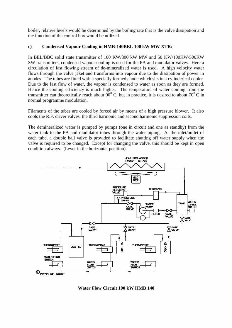
c) Condensed Vapour Cooling in HMB-140BEL 100 kW MW XTR:
In BEL/BBC solid state transmitter of 100 KW/300 kW MW and 50 KW/100KW/500KW
SW transmitters, condensed vapour cooling is used for the PA and modulator valves. Here a
circulation of fast flowing stream of de-mineralized water is used. A high velocity water
flows through the valve jaket and transforms into vapour due to the dissipation of power in
anodes. The tubes are fitted with a specially formed anode which sits in a cylinderical cooler.
Due to the fast flow of water, the vapour is condensed to water as soon as they are formed.
Hence the cooling efficiency is much higher. The temperature of water coming from the
transmitter can theoretically reach about 900 C, but in practice, it is desired to about 70
0 C in
normal programme modulation.
Filaments of the tubes are cooled by forced air by means of a high pressure blower. It also
cools the R.F. driver valves, the third harmonic and second harmonic suppression coils.
The demineralized water is pumped by pumps (one in circuit and one as standby) from the
water tank to the PA and modulator tubes through the water piping. At the inlet/outlet of
each tube, a double ball valve is provided to facilitate shutting off water supply when the
valve is required to be changed. Except for changing the valve, this should be kept in open
condition always. (Lever in the horizontal position).
Water Flow Circuit 100 kW HMB 140

The water flow rate is monitored by three flow switches at the outlet side of each tube. For
PA tube, the flow switch is set at 37.5 litres/minute and for modulator valve, it is set at 11.5
litres/minute. When the water flow comes below this value, the transmitter will be tripped up
to filament & pump will also be switched off. Off condition through the control electronics
and WFF (Water Flow Failure) fault indication comes ON in the fault indicator panel.
The temperature of the water in the pipes is monitored by 3 thermostats one at the outlet of
each tube. These thermostats are set at an operating temperature of 900 C, the transmitter will
trip automatically to standby condition and WTR (Water Temperature High) indication
comes up in indicator panel. Until the water temperature comes down to normal temperature,
it will not be possible to put ON MT or HT.
The hot water from the valves returns to the tank through a water to air heat exchanger where
it is cooled (100 C to 15
0 C) by blower in the heat exchanger. To ensure good quality of the
water, a part of water is fed through a pressure reducing valve to de-ionizer for regeneration.
A conductivity tester to check the quality of water in terms of conductivity is also available
with the transmitter.
A filter is provided before the pump for filtering the water. The actual filter sleeve can be
removed with the screw plug whenever required for cleaning. Manometers are provided for
indicating the pressures at the inlet and outlet water lines of tubes.
The water level switch senses the level of water and gives indication WLL (Water Level
Low) when the water level in the water tank becomes low. The level switch is a pressure
switch with a stainless steel pressure element. The switching point can be set with the help of
the knob provided in the switch.
More or less the same system is used in the transmitter where the transmitting tubes are of
CQK-25, 50, 350, 650 etc.
5 LIMITERS
Limiting amplifiers are used in transmitter. During a transmission, there may be peaks
occasionally which may overload the modulator valves and trip the transmitter. The
occasional peaks may be for a short duration and it can not be controlled manually.
Modulation of the transmitter also has to be kept very high of the order of 70% or more on
average. To take care of all these things, limiting amplifiers are used in transmitter.
5.1 AM LIMITER (ME 277 DX)
In AIR Limiting Amplifiers of Meltron make ME 277 DX Limiter are being used in large
numbers. Many of the stations may also be using Limiting Amplifiers of BEL make. The
principle of working and the modules used in both the Limiting Amplifiers are same. In the
Meltron Limiter, integrated circuits (mostly operational amplifiers) are used. Whereas the
same function is realised in BEL Limiter using transistors.
Over driving the audio stage of transmitter is protected by the Limiting Amplifier by
employing a combination of pre-delay and feed back control. The audio signal is delayed by
approximately 300 micro second during which time necessary control signal is calculated and

set. The limiter (both Meltron and BEL) uses the combination of compressor and expander
circuits, which increases the audio level (density) as is necessary for extending broadcast in
fringe area.
BROADCAST SPECIFICATIONS OF ME 277 DX LIMITER
Inputs : Input Impedance 600 Ohms
Nominal Input level - 20 dBm to + 15 dBm
Maximum Input level + 24 dBm (12.29 V approx.)
Outputs : Balanced floating impedance maximum 40 ohms.
Nominal output level - 20 dBm to + 15 dBm
Frequency Response 30 Hz to 15 kHz + 0.3 dB
Static Settings :
Limiter threshold At internal nominal level
Compressor Ratio 2 to 6 adjustable
Compressor Gain 0 to 18 dB adjustable
Expander (switchable) - 45 to -65 dB adjustable
Expander ratio 2 fixed
Dynamic Settings :
Attack time : Less than 100 micro secs. Imperceptible due to 300 micro secs delay of the
signal.
Release time : Automatic, programme dependent, switchable to manual and can be adjusted
from 0.5 to 7 seconds.
Signal to Noise Ratio :
Gain = 0 Expander ON-76 dB
Gain = 18 Expander ON-36 dB
Gain = 18 Expander OFF-59 dB
Harmonic Distortion : Less than or equal to 0.2%.
5.11 BRIEF WORKING OF THE LIMITING AMPLIFIER
Meltron Limiter ME 277 DX is a control amplifier. It consists of a limiter, a compressor and
expander. The peaks of the audio signal at the input of the transmitter is prevented for
exceeding a predetermined amplitude and Low level signals are amplified.
The audio signal is controlled using a multiplier signal is weighted by a factor 'g' such that the
output signal corresponds to the desired function.

X
g
INPUT OUTPUT
gx
x
When g = 1, the output = input level
g greater than 1, input is amplified at the output
g less than 1, input is reduced at the output
The factor g depends upon the program signal and is determined in the amplification
computer. In the DX Limiter the Gain Control factor 'g' is obtained with a combination of
signal delay of about 0.3 milli second and feed back control. As shown in fig. 2, the input
signal is delayed before it reaches the multiplier. The amplification factor g is determined
during the delay period.
X
g
AUXILARY MULTIPLIER
X
MULTIPLIER
OUT
GAIN COMPUTER
DELAY
IN
Block Diagram
The amplification factor g itself is ascertained using a feed back regulation system which
consists of a GAIN COMPUTER and Auxiliary multiplier. The auxiliary multiplier and the
multiplier employ identical circuitry, so that g serves directly as a factor for both.
The delay time 0.3 milli sec is brief enough not to disturb comparative listening between the
input signal and output signal, but sufficiently long to allow the control process to have been
completed when the input signal emerges from the delay network, independent of over
driving at the input and practically imperceptible to ear.
5.2 STATIC CHARACTERISTICS
As indicated previously the DX-Limiter includes a limiter, compressor and expander.
Limiter
The limiter prevents all signals from exceeding the pre determined threshold, while signals at
power levels are not affected. The limiter responds to peak amplitudes. Short signal peaks

that are not indicated by conventional level meters like VU meter because of the time
constants employed will nevertheless lead to signal limiting. The limiter will thus protect the
transmitting tubes against arcing.
Compressor
The compressor is to increase the loudness of the modulation signal. This enable broadcasting
coverage for instance to be extended without increasing transmitter power. The compressor
function is by employing a non constant amplification characteristics at medium level. The
closer the level approaches the limiting threshold, the more amplification is reduced.
Expander
An expander is linked directly to the compressor. Low level signals down to level
immediately above the noise level are expanded. As a result the signal level may be boosted
without raising the noise level. Undesirable increase in noise are there by prevented during
pauses in the modulation.Performance of the ME limiting amplifier can be explained first
with reference to its static operating curves.
The amplification factor 1 (0 dB) increases at an angle of 45o up to the limiter threshold and
the output level is equal to the input level. In parallel to this line is the line depicting the
maximum amplification 18 dB to which the compressor can be adjusted. This is termed as
compressor gain. In addition to the gain, the compressor is further characterised by the ratio.
Any setting between 2 and 6 (2:1 and 6:1) may be made. If the compressor ratio is 6:1 a 6 dB
increase in the input level will produce only 1 dB increase in the output levels. The circuit of
the compressor designed such that the operating curve is rounded at the top, advancing
smoothly to the limiter region without an abrupt change.
The second region of non-constant amplification is created by the expander, which is
effective in the lower range of signal. The change in amplification is designed as an
expansion ratio : the expander in the ME 277 DX Limiter exhibits a fixed ratio of 1:2 i.e. if
the input level increases by 1 dB, the output level is increased by 2 dB. Signals are expanded
in an adjustable range such that the threshold of the expander is generally set above the noise
level so that only the signal information is amplified. Increases in the noise during pauses in
the modulation are thus effectively prevented.
Ref.Drg.No:-STI(T)446,(DC198)

5.3 DYNAMIC CHARACTERISTICS
Among the dynamic characteristics, the release performance of a particular interest. All
transient events are completed within the delay time and not perceived an unpleasant.
The ME 277 DX Limiter is characterised by a three segment release curve. It begins with a
holding phase (1) of 40 mili sec to prevent the limiter from reacting a new to every half-wave
of a low-frequency signal, a process which would inevitably cause higher distortion,
immediately thereafter, a rapid release phase (2) follows, which is hardly perceived by the ear
and prevents excessive level and loudness losses. The original amplification is restored,
however, only after a very long, practically inaudible phase (3).
The additional feature of the DX-Limiter is that the release performance is programme
dependent, i.e. controlled from the signal characteristics. Very brief over driving in an
otherwise low signal level will be followed by rapid release, where as an extended high-level
signal with occasionally over-driven peaks will cause a release phase of very long duration.
In this manner, for instance, a short signal impulse will not reduce the level for an in
appropriate interval, while dreaded "pumping" effects will be prevented to a great extent for
signals frequently exceeding the threshold.
Normal Setting of the ME 277 DX Limiter as recommended by DG:AIR :
Expander thresholds - 50 dB
Compressor ratio 2:1
Compressor Gain 18 dB
Nominal input level - 6 dBm
Nominal output level + 6 dBm
Threshold of limiting - 6 dBm
The +6 dBm output of limiting amplifier will be followed by a 6 dB multiple pad for feeding
0 dBm input to the transmitter for100% modulation.
For limiting amplifier alignment, 1 kHz is to be fed from the audio console of control room
through the normal programme chain. The level of the audio console at control room should
be adjusted such that the VU meter indicate + 3VU. Now the limiting amplifier input will be
adjusted at threshold of limiting and the output adjusted to 95% modulation. During normal
progamme, the VU meter will peak to zero and as such the peak programme level the input of
limiter will always be 3 dB less than the threshold of limiting amplifier.
The above alignment once made, may not be disturbed thereafter.
5.4 FM LIMITER (EMT 266 TX)
Limiters are commonly employed at the programme input of FM Transmitters to protect
against over-deviation. Accurate control of the programme level by a suitable method is
absolutely essential for maintaining the peak deviation below the permitted maximum value.
Usually the level control proceeds the pre-emphasis. If we consider a reference deviation of
+ 40 kHz corresponding to 0 dB at 500 Hz., we have a margin of only 5.5 dB. But the pre-
emphasis circuit that follows, boosts the signal up to 13.5 dB at 15 kHz thereby exceeding the
permissible margin by about 8 dB. If the time constant of level meter is taken into account,

the increase would be still higher. Without limitation or peak clipping this would lead to
intolerable peak deviations. In case the programme level control is affected after the pre-
emphasis, over modulation can be avoided, but the average deviation would be reduced
unnecessarily.
It has thus been realised that the conventional limiter together with the constant pre-emphasis
of 50 microseconds cannot provide any protection. In conventional limiting amplifiers gain
variations affect all sound signals equally i.e. they are not frequency dependent. Tests have
shown that the shortcomings of conventional limiters can be avoided by employment of
frequency selective form of limiter.
As long as the resulting output signal is much below the nominal level, standard 50 micro
second pre-emphasis is employed. When high frequency components of the programme
signals exceed the prescribed limits, pre-emphasis is reduced momentarily to avoid
overloading. Principle of operation of variable or adaptive pre-emphasis followed in the New
Transient Limiter is illustrated in fig. 4. Here pre-emphasis time constant is reduced by
shifting the start of the boost sufficiently towards higher frequencies until the established
threshold can be maintained. The variable time constant is implemented by a quite simple
circuit. The signal is reproduced linearly and over a separate path, with a 6 dB per octave
increasing gain characteristics, and the results are added. The level of the portion with
increasing gain is controlled by a multiplier and thereby determines the pre-emphasis corner
frequency when both portions are summed together.
In AIR VU meters are normally used for aligning and monitoring of levels of programme
chain. The signal levels read on the VU meter are not necessarily the true signal levels of the
bus they are monitoring. Since the VU meter is an average reading meter, the peaks touching
0VU on VU meter may be actually 6 to 8 dB higher. This is very important factor, which is
normally over looked while deciding the threshold point. Till peak reading meters are
introduced in the department, sufficient headroom is necessary to accommodate the margin of
peak readings. Thus, in order to arrive at proper line up settings, implications arising from
various options require due consideration.
Multiplier
Adaptive
Pre-emphasis
Output Time Delay
Gain Computer
Input
Aux.
(a) Block Diagram of ME 266 X
Transmitter Limiter
Multiplier

Outp
ut le
vel
Input level
(b) Variable Pre-emphasis (c) Static operating curve of the ME 266 X Transient diameter
20
10
0
-10
-20
-30
dB
20 dB 10 0 -10 -20 -30
30
20
0
10
-10
-20
dB
20K Hz 2K
P
200
f
20
6 MEDIUM WAVE ANTENNA
When the electromagnetic waves in the medium wave (MW) range are directed towards the
Ionosphere, they are absorbed by the D-region during the day time and are reflected from the
E layer during the night time, which may travel longer distances to cause interferences. The
wave length of MW signals are very large, of the order of few hundred metres, and therefore
the antenna cannot be mounted a few wavelengths above the earth to radiate as space waves.
MW antenna, therefore, have to exist close to the surface of the earth and the Radio waves
from them have to travel close to the earth as ground waves. If the electric vector of such
MW radiation is horizontal, they will be attenuated very fast with distance due to the
proximity of the earth. MW antenna have to be placed vertically, so that they radiate
vertically polarised signals. It is for this reason, all the MW antenna are installed vertically
close to the ground. However vertical wire antenna, inverted 'L' type antenna, top loaded
antenna and umbrella antenna are at a few All India Radio stations. Directional antenna
systems also exist in many All India Radio stations.
6.1 SELF RADIATING MW MAST ANTENNAS
They are broadly of two types :
Mast isolated from ground and fed at its base.
Grounded mast fed at a suitable point along its height
As most of the All India Radio MW towers are of the first category, only they are discussed
here.
The first consideration of such mast is its height in terms of the wave length. What is the
optimum height ? Obviously the main considerations are economy consistent with maximum
coverage and minimum high angle radiation (sky wave).
The relative characteristics of mast height 30o to 225
o (electrical lengths) are given below :

Electrical height in
degrees
Height in wave length
()
Field strength at one
mile V/m
Polar
pattern
30 1/12 186 Please
60 1/6 189 See
90 1/4 196 Fig. 12
135 3/8 214
180 1/2 242
190 0.53 254
225 5/8 276
From the above analysis, it may be seen that as the height of the MW mast increases, the
field strength at one mile increases (range of the transmitter increases) and is maximum for
225o (5/8) of electrical length of the antenna. Examination of the polar
MW Antenna isolated from ground Ref. Drg.No:-STI(T)851,(DC603)
pattern shows that as the height increases, the high angle radiation decreases and the
horizontal gain increases. However at 5/8 height, the presence of side lobe will contribute
high angle radiation and therefore sky waves. Therefore electrical length of 190o (0.53)
would look optimum from the points of view of maximum range, high horizontal directivity
and maximum suppression of high angle radiation. 190o antenna is known as 'Antifading'
broadcast antenna as it eliminates the sky wave interference fading beyond the ground wave
range during night.
The height of the MW tower also will have to be coordinated with the civil aviation
authorities from the point of view of nearness of the airport. Should this require reduction in
actual physical height top loading technique can be adopted. This increases the current
distribution in the vertical portion of the radiator, thereby increases the efficiency of
radiators.

However in special cases such as the AIR's National Channel at Nagpur, the stress is
particularly for the night time service, to provide more sky wave average for which two short
antenna of 60m height (0.3) fed suitably are used.
The MW self supporting mast antenna could be excited in 3 different methods.
The first method requires an insulator at the base of the mast. The second method is called
shunt feed and the third top feed. The comparatively low voltage at the base and top of the
mast antenna, simplifies the operating condition of the insulators and enables to
accommodate a larger power into the mast antenna, than the wire antenna.
Shunt feed, earthed mast overcomes the difficulties of installing and maintaining masts
placed on insulators. The feed line is usually connected to the mast at a height equal to 1/5 to
1/10 the height of the mast.
Polar Patterns
The top fed antenna is fed by means of a coaxial line (or wires vertically forced inside the
body of the mast). The advantages are
More uniform current distribution compared to the base feed.
Absence of supporting insulator
High radiation resistance and high efficiency
6.2 TOP LOADED ANTENNA
It is possible to simulate higher electrical length of the MW antenna for any physically
smaller MW antenna by top loading. A large capacitance disc (insulated from the mast, and
series resonated by an inductance connected across the insulator at the top of short mast
effectively increases the electrical length of the mast.

Another alternative is to use a number of wires in the form of umbrella emanating from the
top of the radiator and secured via insulated rope to the ground . This is particularly valuable
for thin masts. One such umbrella antenna is installed in Nagarcoil; and some other stations
of AIR.
Umbrella Antenna
6.3 'T' AND 'L' ANTENNA
'T' and 'L' antenna find application in broadcasting. AIR have used such types of MW
antenna in the network. This may perhaps be very handy to rig up one for emergency
arrangements. The antenna is secured on two high (100 to 250m) mast (wood or metal),
spaced 100-250 m apart.
The antenna consists of two to sixteen wires spaced 1 to 1.5 m apart. The copper wires are
usually 5 to 8 mm in diameter. The supporting towers may be secured by several tiers of
guys in which insulators are inserted. The antenna down leads directly connect the radio
transmitter. There may not be any need for feeder lines if suitably structured.
The disadvantages are :
Need for two or more masts
Distortion of directional diagram caused by the influence of supporting cables.
The voltage at the base and at the end of wire antenna is very high compared to the mast
antenna,

25M 'T' Antenna
Inverted 'L' Antenna
6.4 NEED FOR EARTH RADIALS
The MW propogates close to the earth as ground waves. The MW mast also is placed close
to the ground. The electric field in the mast extends from the top to the ground. Current
density of typical /2 tower being significant upto 0.37 to 0.4 wave length and current flows
through the ground back to the mast. The electric field passes through the ground. The earth
usually is not a perfect conductor and field may be attenuated. In order to improve the earth

conductivity when it takes off from the mast the conductivity of the earth around the mast is
artificially increased by burring about 120 radial copper wires of about 0.4 long (usually 10
swg) at 4 to 12 inches deep. The radial wires are suitably brazed among them forming a
mesh.
6.5 MATCHING THE MW ANTENNA
The MW Power Amplifier output has to be matched to the feeder line which again is to be
matched to the antenna impedance usually by a PI/T/L- network in the Antenna tunning unit
located close to the base of the mast for perfect match. The impedance of the mast at the feed
points can be measured by an impedance bridge VIM. Usually the individual component
values of the PI/T/L-matching networks could be computed using transmitter manufacturer's
information booklet.
6.6 GUY SUPPORT FOR MW MAST
The guy wires are used at a number of levels depending upon the height of the tower, its
cross section, the maximum wind velocity expected in that region etc. The guy wires have to
be insulated from the mast so also the guys are broken into a number of small sections /10
or /12 separated by low loss, high mechanical strength insulators to minimise distortion of
radiation pattern due to field induced in them. These insulators are shunted by suitable
inductors to provide d.c. path for lightning discharges while at the same time blocking the
MW energy from earthing. A high resistance shunt across the insulator is another method of
allowing the static leaks. Some types of insulators have built in thyristers which provide low
resistance to high static charge while presenting high resistance for low voltages. Ultraviolet
detectors which is sensitive to arcs or spark overs may also be used to activate the protective
devices in the transmitter.
Directional MW antenna, using more than one vertical mast exist in a number of stations like
Jullandar, Nagpur (National Channel) in the network. Special care must be taken to allow for
proper bandwidth of the directional antenna system.
They guy tensions are usually given in the completion report. It is necessary to measure the
Guy tensions as per AIR technical manual to ensure the verticality or absence of twist in the
mast. Measurement of verticality and twist of the mast are also required to be carried out as
per AIR Technical Manual. Loss of verticality will affect the range of the service due to
earth's proximity
7 FM ANTENNA AND FEEDER CABLE SYSTEM
The Antenna system for FM Transmitters consists of 3 main sub-systems, namely :
a) Supporting tower
b) Main antenna
c) Feeder Cable

7.1 TOWER
A tower of good height is required for mounting the FM antenna since the coverage of the
transmitter is proportional to the height of the tower. For a 100 m height, the coverage is
about 60 km. Wherever new towers were to be provided, generally they are of 100 m height
since beyond this height, there is steep rise in their prices because of excessive wind load on
the top of the tower. At some places existing towers of Doordarshan have also been utilized
for mounting the FM antenna. Provision has also been made on the AIR towers for top
mounting of TV antenna below FM antenna (Aperture for Band III).
7.2 ANTENNA
The main requirements of the antenna to be used for FM transmitters are :
- Wide-band usage from 88 to 108 MHz range.
- Omni-directional horizontal pattern of field strength.
- Circular polarization for better reception.
- High gain for both vertical and horizontal signals.
- Two degrees beam tilt below horizontal
- Sturdy design for maintenance-free service.
Further, depending on the type of tower available for mounting the requirement is for two
types of antenna. The first type is to be mounted on a small cross-section AIR Tower. For
which a pole type FM antenna has been selected. For mounting on the existing TV towers, a
panel type antenna has been used. The cross section of the TV tower at the AIR aperture is
2.4 x 2.4 m. the pole type antenna is quite economical as compared to panel type antenna,
but it can not be used on large area towers. For our requirement, the antennae supplied by
M/s. SIRA have been found suitable.
7.21 POLE TYPE ANTENNA
The pole type antenna is mounted on one of the four faces of the tower. This system will
give a field pattern within a range of 3 dB. The antenna is mounted in such a direction in
which it is required to enhance the signal. The important parameters for this antenna are :
Weight 200 Kg. (for 6 dipoles).
VSWR 1.4 : 1
Gain 5 dB
Rating of each dipole 5 kW
The other important features are :
Very low power radiation towards Transmitter building.
Spacing between dipoles is 2.6 m and all the dipoles are mounted one above
the other on the same face.
Lengths of feed cables of dipoles will be different and has been calculated to give
a beam tilt of 2o below horizontal.

The feed point of the antenna is looking towards ground so as to avoid
deterioration of the insulating flange. This flange consists of high density PVC.
The life of this is expected to be about 7 to 10 years.
The distance of the feeding strip is 240 mm from edge and this should not be
disturbed. All the six dipoles are mounted on a 100 mm dia Pole. This pole is
supported by the main tower.
The antenna is fed through a power divider which divides total power into 6
outlets for feeding the 6 dipoles. The power divider is mounted on a different face
of the tower.
The main feeder cables, power divider branch feeder cables, and dipoles are of
hollow construction to enable pressurization of the system.
The antenna can handle two channels with diplexing.
Suitable terminations are supplied for terminating the output of power divider in
case of failure of any dipole.
7.22 PANEL TYPE ANTENNA
The panel type antenna is to be used on TV tower. Doordarshan have provided an
aperture for FM antenna on their towers. The size of this section is 2.4 x 2.4 mtrs. and its
height is different at different places. The antenna system envisaged for FM broadcasting
consists of a total of 16 panels. For omni-directional pattern 4 panels are mounted on
each side of the tower. Ladders for mounting these panels have already been provided on
the four sides of the tower.
Each panel consists of :
Reflector panel
Two numbers of bent horizontal dipoles and
Two numbers of vertical dipoles
The capacity of each dipole is 2.5 kW. Therefore, each panel is able to transmit 10 kW
power. The reflector panels are constructed of GI bars whereas the dipoles are made out
of steel tubes. Since each panel consists of 4 dipoles, there are a total of 64 dipoles for all
the 16 panels. Therefore the power divider has 64 outlets to feed each of the dipoles. The
power divider will be mounted inside the tower. This antenna gives an omni-directional
pattern when the panels are mounted on all the four faces.
7.3 FEEDER CABLE
For connecting the output power of the transmitter to the dipoles through the power
divider, a 3” dia feeder cable has been used.
This cable is of hollow type construction and has to be handled very carefully. From the
building to the base of the tower, the cable is laid on horizontal cable tray. Along with
the tower this is fixed on the cable rack provided for this purpose. The cable is clamped

at every 1.5 m and the minimum radius of bending of this cable is about 1 m. The cable
has been provided with two numbers of EIA flange connectors of 3 1/8” size on both
ends. Both the connectors are of gas-stop type. The cable connector on the antenna end
i.e. on top of the tower is made gas-through before hoisting. This is achieved by drilling a
hole through the Teflon insulator inside the connector. A dummy hole (drilled only half
way) is already provided by the manufacturer for this purpose.
The weight of the cable is about 2.7 kg per meter and the power handling capacity is about 27
kW. Since enough safety margin has been provided in the power handling capacity, no
standby cable has been provided. This cable can be used later for two transmitters by
diplexing. The attenuation loss of the cable is about 0.44 dB per 100 R.F. Energy of a
transmitter is guided up to radiator (mast) by the propagation of Trans-verse Electro-magnetic
waves along systems of parallel conductors called „Transmission lines or feeder lines‟. The
input energy is stored in the field of conductors and is propagated along the system at some
finite velocity.
It is essential to keep the antenna at a distance from transmitter due to prevent
Radiation hazard
pick up from antenna and consequent problem with transmitter circuit Normally
this distance is either on 50 V/m field strength contour or minimum half the
wavelength at frequency of operation.
The feeder line should carry the power from the transmitter to Antenna with
Minimum loss
Minimum radiation.
7.31 BASIC TRANSMISSION LINES
There are three types of transmission lines used at RF. They are :
(i) Open wire feeder lines
(ii) Co-axial feeder lines
(iii) Wave guides
Characteristics Impedance Of Feeder Lines
Characteristics impedance (Zo) is defined as the input impedance of an infinite line. This is
determined wholly by the geometry of its cross section. A transmission line can be
represented as having R, L,C.
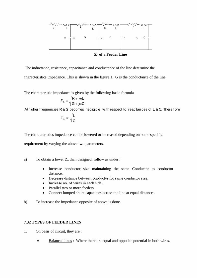
Zo of a Feeder Line
The inductance, resistance, capacitance and conductance of the line determine the
characteristics impedance. This is shown in the figure 1. G is the conductance of the line.
The characteristic impedance is given by the following basic formula
C
LZ
foreThere.C&Lofcestanreactorespectw ithnegligiblebecomesG&RsfrequenciehigherAt
CjG
LjRZ
o
o
The characteristics impedance can be lowered or increased depending on some specific
requirement by varying the above two parameters.
a) To obtain a lower Zo than designed, follow as under :
Increase conductor size maintaining the same Conductor to conductor
distance.
Decrease distance between conductor for same conductor size.
Increase no. of wires in each side.
Parallel two or more feeders
Connect lumped shunt capacitors across the line at equal distances.
b) To increase the impedance opposite of above is done.
7.32 TYPES OF FEEDER LINES
1. On basis of circuit, they are :
Balanced lines : Where there are equal and opposite potential in both wires.

Unbalanced lines : Here one wire is at high potential and the other side is at
low potential.
2. Structurally there are two basic forms :
(I) Open wire line (ii) Enclosed line.
Open wire feeder lines
dSZ /2log2760
S
d
In MW band, normally the feeder lines used are unbalanced and has following characteristics.
6 wires, 230 Ohms
16 wires, 120 Ohms
24 wires, 60 Ohms
In SW, normally the balanced feeder lines are used. The impedances are
300 ohms, 4 wire
600 ohms, 2 wire
3. Basic Applications of feeder line :
To guide energy from transmitter to Antenna. In this mode energy move
along the lines in a single travelling wave.
For Storing energy in excess of that dissipated in load, in the form of standing
waves.
7.33 LOSSES IN THE FEEDER LINES
There are four types of losses. They are :
Copper Loss : It is due to the heating of conductor.
Earth Loss : It arises due to imperfect earth conductivity.
Insulation Loss : It is due to insulation loss and is minor in a well designed
system.
Radiation Loss : It is due to irregularity and usually very small for well
designed lines.

Copper Loss
R.F. Wave travels along the exterior of a conductor due to skin effect. The conductor gets
heated up resulting in losses in the feeder line. It can be reduced by increasing the radius
of conductor and also by using more no. of wires in parallel. It is directly proportional to
square root of frequency, so higher the frequency, more the losses.
Earth Loss
In unbalanced open wire lines there is division of charges between ground wires and that
induced in the earth under feeder lines resulting in part of the return current in the ground.
The rotation of return current in the grounded wires and to the total current in live wires
decides earth losses. It can be reduced by laying two nos. of copper wires in the ground
through out the length of feeder wire line and by increasing the height.
Radiation Loss
One cause of radiation from open lines is from the vertical connections at the ends.
Decreasing the height can reduce it, but if height is decreased, the ground losses will increase.
So best way-out is to use better shielding of high potential wires by using greater number of
ground wires.
7.34 CHOICE OF FEEDER LINE IMPEDANCE
When the feeder line impedance is chosen low, feeder current will be more, resulting increase
in copper loss and earth loss. When feeder line impedance is high, feeder voltage will be
high resulting in the use of higher voltage rating insulators. So the choice depends upon the
availability of components and technology in use.
In AIR, following types of feeder lines are used.
230 ohm 6 wire (open wire) lines – for all old 100 kW as well as 10/20 kW.
60 ohm quasi coaxial feeder line - megawatt of Chinsuraha, Rajkot and
Nagpur.
120 – ohm quasi coaxial feeder - all 300 kW and all 100/200 kW new version.
120 ohm feeder line is now standardised for modern transmitters.
7.35 230 OHMS COPPER WIRE FEEDER LINE
This type of feeder line is most popular and has been used in all old installations of
10/20/100 kW/MW XTRs. There are total 6 wire (8 SWG, app 4.064 mm). Two inner are
on high potential and four outer are ground conductors

7.36 QUASI COAXIAL FEEDER LINE
In this category of line normally there are two designs :
In which there are 8 inner wires and 8 outer wires each of 8 SWG. This has been
used in all 100/200/300 kW XTRs.
In which there are 12 inner conductors of 6 mm dia and 16 screen conductors of 8
SWG and this has been used at 1000 kW Nagpur, Calcutta (Chinsuraha) and
Rajkot.
Measurement Of Characteristic Impedance, Zo
Zo of a feeder line is given by the relation
scoco Z.ZZ
Zoc = Open circuit Impedance, measured at input by keeping the feeder line end open
Zsc = Short circuit Impedance, measured at input by keeping the feeder line end short
Generally Zoc & Zsc are either capacitive or inductive depending upon the length of feeder
line as multiple of /4.
Zoc & Zsc can be measured with VIM or RF bridge by keeping the line open and shorting
high potential wire (inner) with ground wire (outer) at other end.
Another method utilises the fact that when the feeder line is terminated by its characteristic
impedance, its input impedance is equal to the characteristic impedance. Input impedance is
measured for various termination. The characteristic impedance is equal to that termination
for which input impedance is same as the termination itself.
Pmeter length. The cable and the antenna system should be fed with dry air by means of
a dehydrator provided with the transmitter.
7.37 POWER HANDLING CAPACITY OF FEEDER LINES
The power handling capacity of a line depends upon :
Nos. of live wires used in parallel.
The charge density per unit surface of the wire.
Maximum allowable potential gradient to avoid flashover, and corona etc.
Power handling capacity of a line (120 ) is calculated as below : RF Current carrying
capacity of copper conductor x dia of live conductor in inches = 76.2 x .1574 = 10 Amp.
For 8 wires total current is = 10 x 8 = 80 Amp.
Therefore, power handling capacity = I2 x R = (80)
2 x 120 = 768 kW say, 760 kW.
In practice, the maximum voltage that a line can handle/withstand with out flashover etc. is
80% of the D.C. Value of max. voltage.

7.38 PRECAUTION WHILE ERECTING A FEEDER LINE
Bends should be gradual and free of any sharp corners (preferably of 120o or so).
The exact and equal length of wires should be used at bends. To keep the length
same is more important than to maintain the equal spacing as it increases the
series inductance of line.
The poles should be placed at equal distance and symmetrically (app. 15 mtr),
Splitting joints should be smooth and free of any irregularity.
The height above ground should be uniform otherwise ground return current will
differ, varying the earth losses.
8 SATELLITES
Today satellites are used for communication for the following reasons as given below:
1. Multiple access capability, i.e. point-to-point, point-to-multipoint or multipoint to
multipoint connectivity,
2. Distribution capability (a particular case of point-to-multipoint transmission), including t v
programme broadcasting, data distribution e.g. for business services, internet wideband
services, etc., flexibility for change in traffic and in network architecture and also ease of
operation and putting into service.

8.1 SATELLITE SERVICES 1. FIXED SATELLITE SERVICE (FSS):
According to radio regulations (rr no. s1.21), the FSS is a radio communication service
between given positions on the earth's surface when one or more satellites are used. These
stations located at given positions on the earth's surface are called Earth Stations of the FSS.
The given position may be a specified fixed point or any fixed point within specified areas.
Stations located on board the satellites, mainly consisting of the satellite transponders and
associated antennas, are called Space Stations of the FSS. All links between the transmitting
Earth Station and receiving Earth Station are effected through a single satellite. These links
are comprised of two parts,
an Uplink between the transmitting Earth Station and the satellite
a Downlink between the satellite and the receiving Earth Station
Links between two earth stations could use two or more satellites directly interconnected
without an intermediate earth station. The satellite-to-satellite links are called inter-satellite
service (ISS).

2. MOBILE SATELLITE SERVICE (MSS):
According to radio regulations (rr no. s1.25), this is a radio communication service between
mobile earth stations and one or more space stations.This includes
Maritime Mobile Satellite Service (MMSS)
Land Mobile Satellite Service (lMSS)
Aeronautical Mobile Satellite Service (AMSS)
3. BROADCASTING SATELLITE SERVICE (BSS):
This is a radio communication service in which signals transmitted or retransmitted by space
stations are intended for direct reception by the general public using very small receiving
antennas (tvros). The satellites implemented for the BSS are often called direct broadcast
satellites (DBSS). The direct reception shall encompass both individual reception (DTH) and
community reception (CATV and SMATV).
8.2 Geostationary Satellite Orbit (GSO):
Most communication satellites with a few exceptions describe a circular orbit on the
equatorial plane at an altitude of about 36,000 km, resulting in a 24 hour period of revolution
round the centre of the earth. They are thus synchronous with the earth's rotation and appear
relatively motionless in relation to a reference point on the earth's surface. They are
consequently located on the geostationary-satellite orbit (GSO). This characteristics enables
the satellite to provide permanent coverage of a given area, which simplifies the design of

earth stations, since they are no longer required to track satellites moving at considerable
angular velocities and makes more efficient use of radio spectrum and orbital resources.
8.21 COVERAGE:
Satellite links allow for communication between any points on the earth's surface, without
any intermediate infrastructure and under conditions (technical, cost, etc.) which are
independent of the geographical distance between these points, provided they are located
within the satellite coverage area. In the case of GSO satellite, the points to be served must be
situated, not only in the region of the earth, visible from the satellite, but also within the
geographical areas covered by the beams of the satellite antennas: these areas arecalled the
coverage areas of the communication satellite system.
"Round an axis of revolution passing through the centre of the earth and the satellite, this
area falls within a cone with the satellite at its apex and apex angle of 17.3˚ which also
corresponds to a cone with the centre of the earth at its apex and an apex angle of 152.7˚.
These conditions describe an area from which the satellite is visible from the earth stations at
an angle of at least 5˚ above the horizontal direction."
8.22 PROPAGATION DELAY
An important feature of the satellite link is the propagation delay. In the case of GSO
systems, owing to the distance of the geostationary satellite from the earth, the propagation
time between two stations via the satellite can reach approximately 275 milliseconds.
8.3 MULTIPLE ACCESS
Multiple access is the ability for several earth stations to transmit their respective carriers
simultaneously to the same satellite transponder. This feature allows any earth station located
in the corresponding coverage area to receive carriers originated by several earth stations
through a single satellite transponder. Conversely, a carrier transmitted by one station into a
given transponder can be received by any earth station located in the corresponding coverage
area. This enables a transmitting earth station to group several carriers into a single
destination.

8.31 FREQUENCY DIVISION MULTIPLE ACCESS (FDMA)
In FDMA, each earth station is allocated a specific frequency (with the necessary bandwidth)
for the emission of a carrier forming part of a multiple-destination multiplex. Each of the
corresponding station must receive this carrier and extract the channels intended for it from
the baseband. FDMA is often associated with frequency division multiplexing (FDM).
However, FDMA can also be combined with other types of multiplexing and modulation,
especially time division multiplexing (TDM) with digital modulation, which generally uses
phase shift keying (PSK).
8.32 TIME DIVISION MULTIPLE ACCESS (TDMA)
In TDMA, each station is periodically allocated, on the same carrier and within a "frame", a
period of time (a burst), during which it emits a digital signal forming part of a multiple-
destination multiplex. Each corresponding station receives this burst and extracts from it the
digital channels intended for it. multiplexing associated with TDMA is effected by TDM, the
telephone (or data transmission) channels being themselves coded digitally (e.g. PCM). The
carrier is generally phase shift keyed by the digital signal.

8.33 CODE DIVISION MULTIPLE ACCESS (CDMA):
In CDMA, the transmitted signals are not discreminated by their frequency assignment (as in
FDMA) nor by their time slot (as in TDMA), but by a characteristic code which is

superposed on the information signal. Multiple access can also result from various
combinations of FDMA and/or TDMA and/or CDMA and can be performed or changed in
the satellite by on board processing (OBP).
8.4 TRANSPONDER:
Basically, satellite transponders receive, amplify, frequency translate and retransmit various
types of communication signals. Therefore, a transponder is the series of interconnected
units which forms a single communication channel between the receive and transmit antennas
in a communication satellite.

8.5 Altitude and Orbit Control System (AOCS):
This subsystem consits of rocket motors that are used to move the satellite back to the correct
orbit when external forces cause it to drift off station and gas jets or inertial devices that
control the attitude of the spacecrafts. Control of the attitude of a spacecraft is necessary so
that the antennas, which often have narrow beams, are pointed correctly at the earth.
8.51 ALTITUDE CONTROL SYSTEM:
There are two ways to make a spacecraft stable when it is in orbit and weightless. The entire
body of the spacecraft can be rotated at 30 to 100 rpm to provide a powerful gyroscopic
action, which maintains the spin axis in the same direction, such spacecrafts are called
spinners. Alternatively, three momentum wheels can be mounted on three mutually
orthogonal axes of the spacecraft to provide stability. The momentum wheel is usually a
solid disk driven by a motor, rotating at high speed within a sealed, evacuated housing.
Increasing the speed of the wheel increases its angular momentum, which causes the
spacecraft to proceed in the opposite direction, according to the principle of conservation of
angular momentum. With three momentum wheels, rotation of the spacecraft about each axis

can be commanded from earth by increasing or decreasing the appropriate momentum wheel
speed. This is called three-axis stabilization.
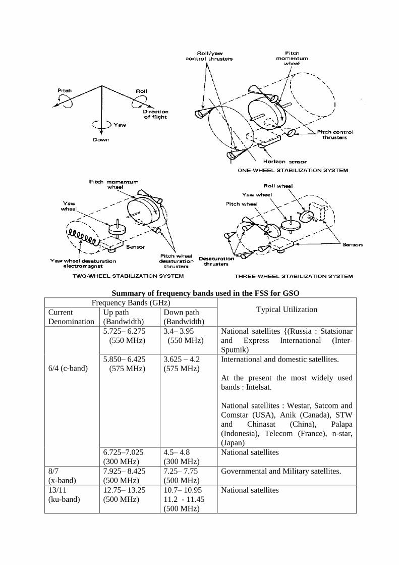
Summary of frequency bands used in the FSS for GSO
Frequency Bands (GHz) Typical Utilization Current
Denomination
Up path
(Bandwidth)
Down path
(Bandwidth)
6/4 (c-band)
5.725– 6.275
(550 MHz)
3.4– 3.95
(550 MHz)
National satellites {(Russia : Statsionar
and Express International (Inter-
Sputnik)
5.850– 6.425
(575 MHz)
3.625 – 4.2
(575 MHz)
International and domestic satellites.
At the present the most widely used
bands : Intelsat.
National satellites : Westar, Satcom and
Comstar (USA), Anik (Canada), STW
and Chinasat (China), Palapa
(Indonesia), Telecom (France), n-star,
(Japan)
6.725–7.025
(300 MHz)
4.5– 4.8
(300 MHz)
National satellites
8/7
(x-band)
7.925– 8.425
(500 MHz)
7.25– 7.75
(500 MHz)
Governmental and Military satellites.
13/11
(ku-band)
12.75– 13.25
(500 MHz)
10.7– 10.95
11.2 - 11.45
(500 MHz)
National satellites

13-14 /11-12
(ku-band)
13.75– 14.5
(750 MHz)
10.95– 11.2
11.45– 11.7
12.5 - 12.75
(1000 MHz)
International and domestic satellites in
region 1 and 3. Intelsat, Eutelsat,
(Russia) Eutelsat, Telecom 2 (France),
DFS Kopernikus (Germany), Hispasat –
1 (Spain)
10.95– 11.2
11.45– 11.7
12.5– 12.75
(750 MHz)
International and domestic satellites in
region
2. Intelsat, Anik b and c (Canada), g-
star (United States), Hispasat-1 (Spain)
18/12 17.3 - 18.1
(800 MHz)
bss bands Feeder link for BSS plan
30/20
(ka-band)
27.5– 30.0
(2500 MHz)
17.7– 20.2
(2500 MHz)
International and National satellites,
various projects under study (Europe,
United States, Japan), n-star (Japan),
Intalsat (Italy)
9 ANALOG/DIGITAL RADIO NETWORKING RECEIVE TERMINAL
The analog/digital radio networking receive terminal is used to receive satellite radio signal
to feed the relay transmitter or for monitoring purpose. The basic system consists of a
parabolic dish antenna with feed, outdoor units (LNBC) and indoor units consisting of:
1. LNBC C/O Unit
2. Two Analog Receiver and two Digital receivers with low loss RF cable connecting
outdoor units to indoor units.
The integrated system is designed to satisfy the overall performance of Radio Networking
Receive Terminal, essentially the end results with an interconnecting low loss RF cable of
length 50m between outdoor and indoor units. Also separate 3 core cable assembly of 50m
lengths is connected between indoor units for LNBC change over. Biasing to LNBC is
supplied through RF cable.
The Analog/Digital Radio Networking Receive Terminal receives the signal in frequency
range 2.5 to 2.7 GHz (S Band) through 3.66m P.D.A. This signal is converted to 950 to 1150
MHz in the Low Noise Block Converter (LNBC). The down converted L Band signal is fed
to LNBC change over unit through 50m long low loss cable. The LNBC change over unit
provides biasing to the selected LNBC through the same RF cable. LNBC change over
monitors the health of selected LNBC and in case of failure change over to standby LNBC is
done through control cable (3 core). L Band RF signal received by LNBC changeover unit is
divided into four by four way splitter. L Band outputs from four-way splitter are connected to
two Analog and two Digital receivers through F to N low loss of 2m lengths.
The Analog and Digital receivers further down convert and demodulates these signals to
provide rebroadcast quality audio output.
9.1 COMPOSITION OF RADIO NETWORKING RECEIVE
TERMAINAL
The Analog/Digital Radio Networking Receive Terminal consists of following subunits:

1. 3.66m PDA
2. LNBC
3. LNBC change over
4. Coaxial cable
5. Cable assembly-3 core
6. Digital Audio Receiver with L Band input
7. Analog SCPC receiver with L Band input
8. Cable assembly N (M) to F (M)
TECHNICAL SPECIFICATION
Specification of Antenna
Type and Size : PDA (Perforated aluminum alloy)
3.66m Dia.
Receive Band : S - Band
Feed : Prime Focus
Polarization : LHCP
Frequency Band : 2.5-2.7 GHz
Gain : > 36.5 dBi (Nominal) at 2.5 GHz
Radiation/Receive Pattern : As per CCIR Rec. 580-1
Type of Mount : Elevation over Azimuth
Antenna Drive : Manual
Pointing Accuracy : Better than +/- 0.5 deg.
Steerability : Elevation : 30-80 deg.
Azimuth :+/- 30 deg.
V.S.W.R : 1.3 Max.
Feed Return Loss : 15 dB
Wind Speed : Operational : 75 Kmph
Survival : 160 Kmph
Axial Ratio : 3.5 dB
Focal length/Dia : 0.4
Feed Impedance : 50 0
Specification Of LNBC
Input Frequency : S-Band (2.5-2.7 GHz)
Output Frequency : L-Band (950-1150 MHz)
Noise Temperature : < 45 K
Conversion Gain : >50 dB
Gain Flatness : < 2 dB p-p in any 40 MHz Band
Gain Variation : < 2 dB p-p
Minimum Image Rejection : -60 dB
Input Return Loss : 12 dB
Output Return Loss : 12 dB
Spurious/Harmonics : -50 dBc
LO Stability : Better than +/- 2 ppm

Phase Noise
1 KHz : -60 dBc
100 KHz : -80 dBc
Specification of Analog Receiver
Input Frequency : 950-1450 MHz
C/No Threshold : 64 dBHz
Input Impedance : 75
Transponder Tuning : 1-24
I.F Frequency Tuning : 50-90 MHz
Tuning Steps : 10 KHz
Demodulation : FM
De- Emphasis : 75 sec
Audio Expanding : 1:2
Line Output : -10 to +9 dBm
Audio Distortion : < 1%
Audio Frequency Response : 30 Hz-15 KHz
S/N : 65 dB
Audio Output Impedance : 600
Specification of Digital Receiver
Input Frequency : 950-1450 MHz
Input Level : -30 to –70 dBm
Input Impedance : 75
Frequency Resolution : < 25 KHz
De-modulation : QPSK
Carrier Lock Range : Better than +/- 1.0 MHz
FEC De-coding : Rate ½ viterbi
Mode : Mono, dual Mono, Joint Stereo
Receiver Eb/No (10-5
BER) : 6.5dBHz (Threshold)
Audio Coding/Compression : ISO MPEG-1 Layer II
Audio Program Channel Rate : 128, 192, 256 Kbps
Audio Output Level : +9 dBm (max) adjustable
Audio Distortion : < 0.5 % ( at +9dBm O/P)
Frequency Response : +/- 1.0 dB (20 Hz – 20 KHz)
S/N : Better than 75 dB
Cross talk : Better than 75 dB
Audio Output Channel : L, R, L+R
Audio Output Impedance : 600
System level specification of Analog/Digital Radio Networking Receive Terminal
S-Band
size : 3.66 m
G/T : 11.7 dB/K
Polarization : LHCP
C-Band

size : 6.1m
G/T : 24 dB/K
Polarization : Linear H/V
System Characteristic
Mode : SCPC
RN Channel Bandwidth : 200 KHz
Sat EIRP EOC/RN carrier : -120 dBm
Analog System
Modulation : Companded FM
Base Band : 10/15 KHz
Compression : 2:1
Pre-Emphasis : 75 sec
Peak Deviation : +/- 75 KHz at + 9 dBm
ED suppression : 40 dBc
Digital System
Modulation : QPSK
FEC : 1/2 Convolution coding
Base Band compression : ISO MPEG-1 Layer II
MUSICAM
selectable rates
Base Band : 20Hz - 20 KHz
Mode : Stereo, Joint Stereo,
Mono, Voice/Data Channel
Insat System Details
CXS Band Transponder S1 S2
Uplink Frequency : 5870 5910
Downlink Frequency : 2570 2610
Polarization : Uplink : linear H/V
Downlink : LHCP
Sat EIRP : 42 dBw
S.F.D. : -90 dBw/m2
CXC Band Transponder
Uplink Frequency Band : 5950-6390
Downlink Frequency Band : 3725-4165
Polarization : Uplink : linear H/V
Downlink : linear H/V
Sat EIRP : 38 dBw
S.F.D : -90 dBw/m2
Brief Description
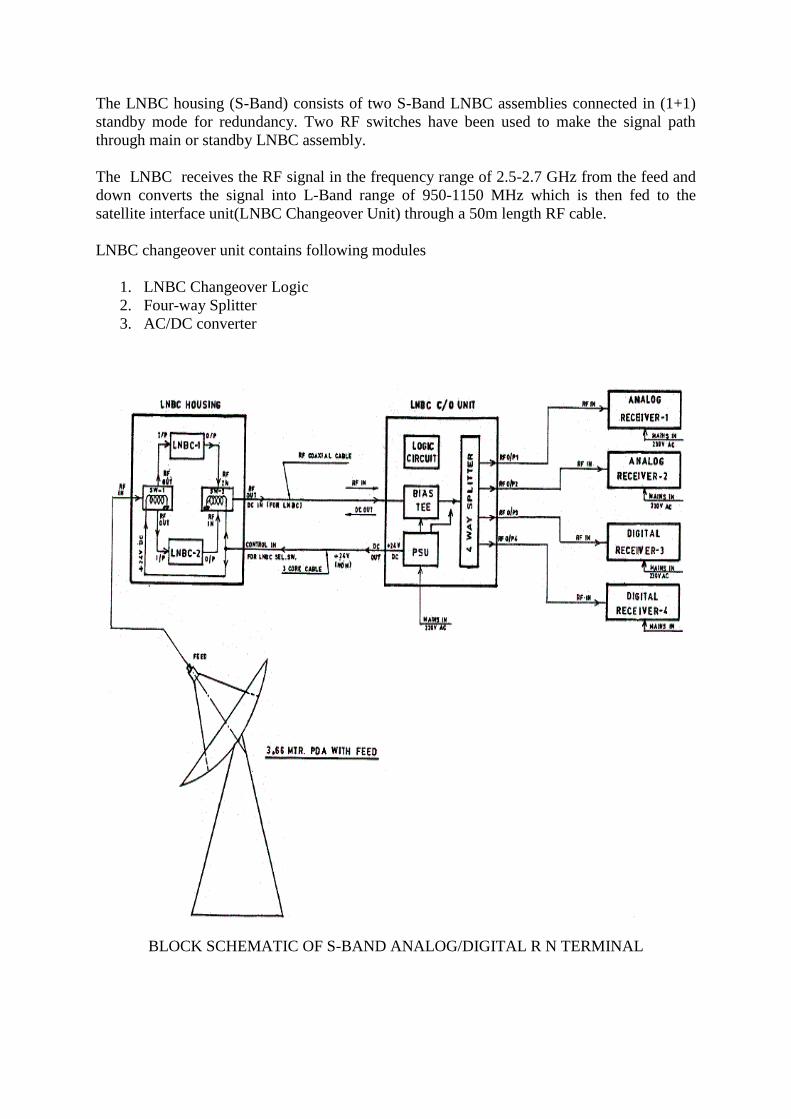
The LNBC housing (S-Band) consists of two S-Band LNBC assemblies connected in (1+1)
standby mode for redundancy. Two RF switches have been used to make the signal path
through main or standby LNBC assembly.
The LNBC receives the RF signal in the frequency range of 2.5-2.7 GHz from the feed and
down converts the signal into L-Band range of 950-1150 MHz which is then fed to the
satellite interface unit(LNBC Changeover Unit) through a 50m length RF cable.
LNBC changeover unit contains following modules
1. LNBC Changeover Logic
2. Four-way Splitter
3. AC/DC converter
BLOCK SCHEMATIC OF S-BAND ANALOG/DIGITAL R N TERMINAL
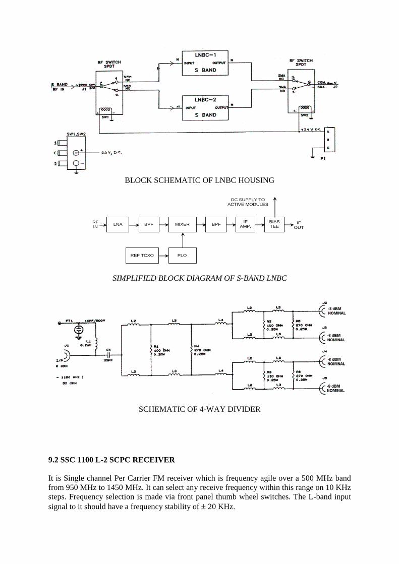
BLOCK SCHEMATIC OF LNBC HOUSING
RF IN
BPF
DC SUPPLY TO ACTIVE MODULES
IF OUT
LNA MIXER
REF TCXO PLO
BPF IF
AMP. BIAS TEE
SIMPLIFIED BLOCK DIAGRAM OF S-BAND LNBC
SCHEMATIC OF 4-WAY DIVIDER
9.2 SSC 1100 L-2 SCPC RECEIVER
It is Single channel Per Carrier FM receiver which is frequency agile over a 500 MHz band
from 950 MHz to 1450 MHz. It can select any receive frequency within this range on 10 KHz
steps. Frequency selection is made via front panel thumb wheel switches. The L-band input
signal to it should have a frequency stability of 20 KHz.

The L-band to IF converter is comprised of three oscillator/mixer combination sub-stages as
well as tracking filter for image rejection. When a carrier is selected using the thumb wheel
switches a set of EPROMs read the switch condition and adjusts the synthesized oscillators
accordingly. This results in an IF that directly represents the programming frequency desired.
The IF is then passed to the programme audio demodulator section. In programme audio
demodulator the selected receive carrier is demodulated, processed and expanded to its
original form. The rear panel contains the facilities for balanced audio output, signal strength
indication and AFC voltage output.
RECEIVER SPECIFICATION
Input Frequency L - band (950 – 1450 MHz)
Carrier Selection 52-88 MHz (10 KHz Steps)
Noise Bandwidth 200 kHz
Companding 2:1, single band
Emphasis 75 sec
Audio Output (nominal) +9dBm Max@ 75kHz deviation
0dBm Max@ 44.7 kHz deviation
@ 600 ohms Bal.Front Panel Adjustable
Frequency Response 1 dB Max.
Audio Response 30 Hz – 15 kHz
Input Connector Type F Female
LNB Power +18 VDC Present on Input Connector Centre
Conductor (300ma max)
THD+N 1 % @ 1 kHz
C/No 68 dB.Hz, operational 64 dB.Hz, threshold,
impulse noise @ one click per second.
Signal to Noise Ratio >75dB@ 75kHz deviation
AC Power 220 VAC @ 50 Hz

CONCLUSION
This vocational training was really a very educative and enlightening experience for
me and my objective of getting exposure to the industrial and the corporate world was
successfully accomplished. I got the opportunity to spend time with the professionals
and learn and get exposure in the governmental organization which is broadly in the
field of communication and broadcasting. I got the opportunity to see various
instruments used in the field of communication like the various antennas, power
supply equipments, the cooling arrangements, microwave devices, various digital
switching circuits, the transmitter, the receiver, etc. and learened how the theoretical
knowledge that is being imparted to us during the curriculum of engineering is applied
in the industries.
In the end, I would once again thank all the people who made such kind of training
possible for me.

REFERENCE
Basic Course in Communication: AIR Study Material
Radio Transmission: AIR Study Material
Antenna and Feeder System: AIR Study Material
FM Transmitter Specifications Handbook: BEL Publication
Handbook on FM Transmitters: GCEL Publication
Cooling Systems: AIR Study Material
Cooling System Technical Specifications Handbook: Voltas Publication
Earthing Systems: AIR Study Material
Studio Acoustics: AIR Study Material
Wireless Communication: Theodore S.Rappaport