Air4G Commissioning Manual SR 10.5 Rev D
217
Customer Service Air4G WiMAX Commissioning Manual System Release 10.5
-
Upload
itachi-redfield -
Category
Documents
-
view
289 -
download
5
Transcript of Air4G Commissioning Manual SR 10.5 Rev D
Customer Service
Air4G WiMAX Commissioning
Manual
System Release 10.5
Air4G WiMAX Commissioning Manual
Page 2 Air4G WiMAX Commissioning Manual Rev D
Table of Contents
Table of Contents .......................................................................................................................... 2
Summary of Figures ...................................................................................................................... 4
Summary of Tables ..................................................................................................................... 10
1 Overview ............................................................................................................................... 11
1.1 Purpose ................................................................................................................................. 11
2 Netspan Provisioning BS Configuration Flow ....................................................................... 12
3 Set BS Management IP & BSID via Web Page .................................................................... 13
3.1 Automatic Discovery via Netspan ......................................................................................... 14
4 Setup of BS Common Profiles .............................................................................................. 17
4.1 MGMT Profile ........................................................................................................................ 18
4.2 VoIP Profile ........................................................................................................................... 19
4.3 Channel Properties – Guide for All Subchannels Network ................................................... 19
4.4 RF Profile .............................................................................................................................. 21
4.5 MCS Profile ........................................................................................................................... 22
4.6 PHY Profile ........................................................................................................................... 23
5 WiMAX Network Architectures Setup ................................................................................... 26
5.1 Standalone, No Authentication, No ASN-GW ....................................................................... 26
5.1.1 Untagged Mode ............................................................................................................ 27
5.1.2 Tagged Mode ................................................................................................................ 35
5.2 Standalone + Authentication (Airspan Free Radius AAA server) + Netspan Provisioning ... 52
5.2.1 Netspan Configuration of Airspan’s FreeRADIUS ........................................................ 53
5.2.2 Untagged mode ............................................................................................................ 55
5.2.3 Tagged Mode ................................................................................................................ 63
5.3 Standalone with Authentication (Any Vendor Radius Server) + Netspan Provisioning ........ 78
5.3.1 Untagged mode ............................................................................................................ 78
5.3.2 Tagged mode ................................................................................................................ 85
5.4 Standalone with Authentication (Any Radius server) + AAA Provisioning ......................... 104
5.4.1 Untagged Mode .......................................................................................................... 104
5.4.2 Tagged Mode .............................................................................................................. 111
5.5 Mobile WiMAX ASN-GW + AAA server .............................................................................. 129
5.5.1 Untagged Mode .......................................................................................................... 129
5.5.2 Tagged Mode .............................................................................................................. 133
5.6 Hybrid Mode - Mobile WiMAX (IP-CS) + Standalone (ETH-CS) ........................................ 140
5.6.1 Untagged Mode .......................................................................................................... 140
5.6.2 Tagged Mode .............................................................................................................. 147
6 Service Products (QoS) Explanation & Creation ................................................................ 164
6.1 IP- Classifiers in ETH-CS Mode ......................................................................................... 172
Air4G WiMAX Commissioning Manual
Page 3 Air4G WiMAX Commissioning Manual Rev D
7 FFR - Fractional Frequency Reuse Configuration .............................................................. 180
7.1 Downlink FFR Configuration ............................................................................................... 180
7.1.1 Configuration Examples .............................................................................................. 181
7.1.2 Uplink FFR Configuration ............................................................................................ 183
7.1.3 UL FFR Configuration Examples: ............................................................................... 184
8 DHCP Option 82 ................................................................................................................. 189
8.1 Implementing Option 82 in network: ................................................................................... 190
8.2 Creating a VLAN profile to be used with the desired Option 82 Mode ............................... 191
8.2.1 Create VLAN Configuration ........................................................................................ 191
8.2.2 Create a new MS VLAN port....................................................................................... 193
8.2.3 Profiles assign procedure: .......................................................................................... 194
9 Applying IEEE 802.1Q-in-Q VLAN Tag .............................................................................. 195
9.1 Implementing Q&Q in network. .......................................................................................... 196
9.1.1 Create VLAN Configuration for Any VLAN ................................................................. 197
9.1.2 Create a new MS VLAN port....................................................................................... 199
9.1.3 Create a new BS network profile ................................................................................ 200
9.1.4 Profiles assign procedure: .......................................................................................... 201
10 Dual Sector Configuration ................................................................................................ 204
10.1 Discovering the BS in Netspan ................................................................................... 204
10.1.1 Set BS Management IP & BSID via Web Page .......................................................... 204
10.1.2 Discovery via Netspan ................................................................................................ 206
10.1.3 Configuring the BS to work as Dual Sector ................................................................ 209
11 Dual MAC-PHY Configuration ......................................................................................... 210
11.1 Discovering the BS in Netspan ................................................................................... 210
11.1.1 Set BS Management IP & BSID via Web Page .......................................................... 210
11.1.2 Discovery via Netspan ................................................................................................ 212
11.1.3 Configuring the BS to work as Dual MAC-PHY .......................................................... 215
12 Appendix A ....................................................................................................................... 216
12.1 Abbreviations .............................................................................................................. 216
12.2 Revision History .......................................................................................................... 216
12.3 Contact Information ..................................................................................................... 217
Air4G WiMAX Commissioning Manual
Page 4 Air4G WiMAX Commissioning Manual Rev D
Summary of Figures
Figure 1 - BS Config .................................................................................................................... 13
Figure 2 - Mgmt IP Config ........................................................................................................... 14
Figure 3 - Discovery tasks ........................................................................................................... 14
Figure 4 - Edit Discovery tasks parameters ................................................................................ 15
Figure 5 - discovery target ........................................................................................................... 16
Figure 6 - Netspan profiles .......................................................................................................... 18
Figure 7 - Management profile .................................................................................................... 19
Figure 8 - VoIP profile ................................................................................................................. 19
Figure 9 - 16e BS Channel .......................................................................................................... 20
Figure 10 - Edit RF profile ........................................................................................................... 21
Figure 11 - MCS profiles ............................................................................................................. 23
Figure 12 - PHY profile ................................................................................................................ 24
Figure 13 - Stand Alone Architecture .......................................................................................... 27
Figure 14 - BS configuration ........................................................................................................ 28
Figure 15 - Service Class - Multicast VLAN ................................................................................ 29
Figure 16 - VLAN Untagged traffic .............................................................................................. 30
Figure 17 - new Network profile .................................................................................................. 30
Figure 18 - Edit MAC profile ........................................................................................................ 31
Figure 19 - Re-provision .............................................................................................................. 32
Figure 20 - New profile ................................................................................................................ 33
Figure 21 - SS tab ....................................................................................................................... 33
Figure 22 - SS management ....................................................................................................... 34
Figure 23 - Mgmt IP Config ......................................................................................................... 35
Figure 24 - Edit Service class ...................................................................................................... 36
Figure 25 - Edit VLAN configuration ............................................................................................ 37
Figure 26 - Add VLAN Bridge profile ........................................................................................... 38
Figure 27 - Network configuration ............................................................................................... 39
Figure 28 - Node Management ................................................................................................... 40
Figure 29 - New profile ................................................................................................................ 41
Figure 30 - SS Tab tab ................................................................................................................ 41
Figure 31 - SS management ....................................................................................................... 42
Figure 32 - Edit VLAN Bridge Profile ........................................................................................... 43
Figure 33 - Edit SS VLAN port profile ......................................................................................... 44
Figure 34 - Edit Node provisioning .............................................................................................. 45
Figure 35 - Node Management ................................................................................................... 45
Figure 36 – Re-provision ............................................................................................................. 46
Figure 37 - Edit SS provisioning .................................................................................................. 46
Air4G WiMAX Commissioning Manual
Page 5 Air4G WiMAX Commissioning Manual Rev D
Figure 38 - New network profile .................................................................................................. 47
Figure 39 - Edit MAC profile ........................................................................................................ 48
Figure 40 - Node management ................................................................................................... 49
Figure 41 - Edit MS custom configuration (16e) profile ............................................................... 50
Figure 42 – SSs Tab ................................................................................................................... 50
Figure 43 - Edit SS provisioning .................................................................................................. 51
Figure 44 - Add AAA Server ........................................................................................................ 53
Figure 45 - Edit AAA client .......................................................................................................... 53
Figure 46 - Add Domain .............................................................................................................. 54
Figure 47 - Add User ................................................................................................................... 54
Figure 48 - Profile-Add ................................................................................................................ 55
Figure 49 - Edit Service Class ..................................................................................................... 57
Figure 50 - Edit VLAN Configuration ........................................................................................... 58
Figure 51 - Edit Vlan Bridge Profile (16e) ................................................................................... 58
Figure 52 - Edit Node Provisioning ............................................................................................. 60
Figure 53 - Node management ................................................................................................... 61
Figure 54 - Edit MS Custom Configuration ................................................................................. 61
Figure 55 - SS Tab ...................................................................................................................... 62
Figure 56 - SS management ....................................................................................................... 62
Figure 57 - Mobile WiMAX BS configuration ............................................................................... 63
Figure 58 - Edit Service Class ..................................................................................................... 64
Figure 59 - Edit VLAN configuration ............................................................................................ 65
Figure 60 - Add VLAN Bridge profile ........................................................................................... 66
Figure 61 - Node properties ........................................................................................................ 67
Figure 62 - Node management ................................................................................................... 68
Figure 63 - SS Tab ...................................................................................................................... 68
Figure 64 - Provisioning .............................................................................................................. 69
Figure 65 - Edit VLAN Bridge Profile ........................................................................................... 70
Figure 66 - Edit SS VLAN Port profile ......................................................................................... 71
Figure 67 - Edit Node Provisioning ............................................................................................. 72
Figure 68 - Node Management ................................................................................................... 73
Figure 69 - SS Tab ...................................................................................................................... 73
Figure 70 - Edit SS provisioning .................................................................................................. 74
Figure 71 - Edit Node provisioning .............................................................................................. 75
Figure 72 - Node management ................................................................................................... 76
Figure 73 - Edit MS custom configuration profile ........................................................................ 76
Figure 74 - SS Tab ...................................................................................................................... 77
Figure 75 - Edit SS provisioning .................................................................................................. 77
Figure 76 - Edit Node profile ....................................................................................................... 79
Air4G WiMAX Commissioning Manual
Page 6 Air4G WiMAX Commissioning Manual Rev D
Figure 77 - Edit Service class ...................................................................................................... 80
Figure 78 - Edit VLAN configuration ............................................................................................ 81
Figure 79 - Edit Vlan Bridge profile ............................................................................................. 81
Figure 80 - Edit Node provisioning .............................................................................................. 82
Figure 81 - Node management ................................................................................................... 83
Figure 82 - Edit MS custom configuration ................................................................................... 84
Figure 83 - SS Tab ...................................................................................................................... 84
Figure 84 - SS management ....................................................................................................... 85
Figure 85 - BS configuration ........................................................................................................ 86
Figure 86 - Edit Node Network profile ......................................................................................... 87
Figure 87 - Edit Service class ...................................................................................................... 88
Figure 88 - Edit VLAN configuration ............................................................................................ 89
Figure 89 - Add VLAN Bridge profile ........................................................................................... 90
Figure 90 - Node properties ........................................................................................................ 91
Figure 91 - Node management ................................................................................................... 92
Figure 92 - SS Tab ...................................................................................................................... 92
Figure 93 - Provisioning .............................................................................................................. 93
Figure 94 - Edit VLAN Bridge profile ........................................................................................... 94
Figure 95 - Edit SS VLAN Port profile ......................................................................................... 95
Figure 96 - Edit Node provisioning .............................................................................................. 96
Figure 97 - Node management ................................................................................................... 97
Figure 98 - SS Tab ...................................................................................................................... 97
Figure 99 - Edit SS provisioning .................................................................................................. 98
Figure 100 - Edit Node provisioning ............................................................................................ 99
Figure 101 – MAC profile .......................................................................................................... 100
Figure 102 - Node management ............................................................................................... 101
Figure 103 - Edit MS custom configuration profile .................................................................... 102
Figure 104 - SS Tab .................................................................................................................. 102
Figure 105 - Edit SS provisioning .............................................................................................. 103
Figure 106 - Edit Node Network profile ..................................................................................... 105
Figure 107 - Edit Service Class ................................................................................................. 106
Figure 108 - Edit VLAN configuration ........................................................................................ 107
Figure 109 - Edit VLAN Bridge Profile ....................................................................................... 107
Figure 110 - Edit Node provisioning .......................................................................................... 109
Figure 111 - Node management ............................................................................................... 110
Figure 112 - SS Tab .................................................................................................................. 110
Figure 113 - Edit SS provisioning .............................................................................................. 111
Figure 114 - Management IP configuration ............................................................................... 112
Figure 115 - Edit Node Network profile ..................................................................................... 113
Air4G WiMAX Commissioning Manual
Page 7 Air4G WiMAX Commissioning Manual Rev D
Figure 116 - Edit Service class.................................................................................................. 114
Figure 117 - Edit VLAN Configuration ....................................................................................... 115
Figure 118 - Add VLAN bridge profile ....................................................................................... 116
Figure 119 - Node properties .................................................................................................... 117
Figure 120 - Node management ............................................................................................... 118
Figure 121 - SS Tab .................................................................................................................. 118
Figure 122 - Provisioning .......................................................................................................... 119
Figure 123 - Edit VLAN bridge profile ....................................................................................... 120
Figure 124 - Edit Ss VLAN port profile ...................................................................................... 121
Figure 125 - Edit Node provisioning .......................................................................................... 122
Figure 126 - Node management ............................................................................................... 123
Figure 127 - SS Tab .................................................................................................................. 123
Figure 128 - Edit SS provisioning .............................................................................................. 124
Figure 129 - Edit Node provisioning .......................................................................................... 125
Figure 130 - Edit Node provisioning .......................................................................................... 126
Figure 131 - Node management ............................................................................................... 127
Figure 132 - SS Tab .................................................................................................................. 127
Figure 133 - Edit SS provisioning .............................................................................................. 128
Figure 134 - Edit Node Network profile ..................................................................................... 130
Figure 135 - Edit Node provisioning .......................................................................................... 131
Figure 136 - Node management ............................................................................................... 132
Figure 137 - SS Tab .................................................................................................................. 132
Figure 138 - Edit SS provisioning .............................................................................................. 133
Figure 139 - Mobile WiMAX BS configuration ........................................................................... 134
Figure 140 - create new network profile .................................................................................... 135
Figure 141 - Edit VLAN Bridge profile ....................................................................................... 136
Figure 142 - Edit Node provisioning .......................................................................................... 137
Figure 143 - Node management ............................................................................................... 138
Figure 144 - SS Tab .................................................................................................................. 138
Figure 145 - Edit SS provisioning .............................................................................................. 139
Figure 146 - Edit Node Network profile ..................................................................................... 141
Figure 147 - Edit Node provisioning .......................................................................................... 143
Figure 148 - Node management ............................................................................................... 144
Figure 149 - SS Tab .................................................................................................................. 144
Figure 150 - Edit SS provisioning .............................................................................................. 145
Figure 151 - Edit MS custom configuration profile .................................................................... 146
Figure 152 - SS Tab .................................................................................................................. 146
Figure 153 - Edit SS provisioning .............................................................................................. 147
Figure 154 - Mobile WiMAX BS configuration ........................................................................... 148
Air4G WiMAX Commissioning Manual
Page 8 Air4G WiMAX Commissioning Manual Rev D
Figure 155 - Edit Node Network profile ..................................................................................... 149
Figure 156 - Edit Service class.................................................................................................. 150
Figure 157 – Edit VLAN configuration ....................................................................................... 151
Figure 158 - Add VLAN Bridge profile ....................................................................................... 152
Figure 159 - Node properties .................................................................................................... 153
Figure 160 - Node management ............................................................................................... 154
Figure 161 - SS Tab .................................................................................................................. 154
Figure 162 - Provisioning .......................................................................................................... 155
Figure 163 - Edit VLAN Bridge profile ....................................................................................... 156
Figure 164 - Edit SS VLAN port profile ..................................................................................... 157
Figure 165 - Node management ............................................................................................... 157
Figure 166 - SS Tab .................................................................................................................. 158
Figure 167 - Edit SS provisioning .............................................................................................. 158
Figure 168 - Edit Node provisioning .......................................................................................... 159
Figure 169 - Node management ............................................................................................... 160
Figure 170 - SS Tab .................................................................................................................. 160
Figure 171 - Edit SS provisioning .............................................................................................. 161
Figure 172 - Edit MS custom configuration profile .................................................................... 162
Figure 173 - SS Tab .................................................................................................................. 162
Figure 174 - Edit SS provisioning .............................................................................................. 163
Figure 175 - Add Packet Classifier Rule Profile ........................................................................ 166
Figure 176 - Add Service Class................................................................................................. 167
Figure 177 - Add Service product ............................................................................................. 168
Figure 178 - Service Flow for Downlink .................................................................................... 168
Figure 179 - Edit Service Product ............................................................................................. 169
Figure 180 - Service Flow Template Configuration ................................................................... 170
Figure 181 - Edit Service Product ............................................................................................. 171
Figure 182 - Add Service Class................................................................................................. 172
Figure 183 - Add Packet Classifier Rule Profile ........................................................................ 174
Figure 184 - Add Service Class................................................................................................. 175
Figure 185 - Add Service product ............................................................................................. 176
Figure 186 - Service Flow for Downlink .................................................................................... 176
Figure 187 - Edit Service Product ............................................................................................. 177
Figure 188 - Service Flow Template Configuration ................................................................... 178
Figure 189 - Edit Service Product ............................................................................................. 179
Figure 190 - 16e BS Channel .................................................................................................... 180
Figure 191 - 16e BS Channel – Group A .................................................................................. 181
Figure 192 - 16e BS Channel - Group B ................................................................................... 181
Figure 193 - 16e BS Channel - Group C ................................................................................... 182
Air4G WiMAX Commissioning Manual
Page 9 Air4G WiMAX Commissioning Manual Rev D
Figure 194 - 16e BS Channel - Group A-B ............................................................................... 182
Figure 195 - 16e BS Channel - Group B-C ............................................................................... 183
Figure 196 - 16e BS Channel - Uplink FFR -1 .......................................................................... 183
Figure 197 - 16e BS Channel - Group A and UL FFR .............................................................. 184
Figure 198 - 16e BS Channel - Group B and UL FFR .............................................................. 185
Figure 199 - 16e BS Channel - Group C and UL FFR .............................................................. 186
Figure 200 - 16e BS Channel - Group A and UL FFR .............................................................. 187
Figure 201 - 16e BS Channel - Group B and UL FFR .............................................................. 187
Figure 202 - 16e BS Channel - Group C and UL FFR .............................................................. 188
Figure 203 - Edit Service class.................................................................................................. 191
Figure 204 - Edit VLAN Configuration ....................................................................................... 192
Figure 205 - new MS VLAN port ............................................................................................... 193
Figure 206 - SS Tab .................................................................................................................. 194
Figure 207 - MS assignment ..................................................................................................... 194
Figure 208 - Edit Service class.................................................................................................. 197
Figure 209 - Edit VLAN Configuration ....................................................................................... 198
Figure 210 - edit MS VLAN port profile ..................................................................................... 199
Figure 211 - Edit VLAN Bridge Profile ....................................................................................... 200
Figure 212 - Node properties .................................................................................................... 201
Figure 213 - Node management ............................................................................................... 202
Figure 214 - SS Tab .................................................................................................................. 202
Figure 215 - edit SS provisioning .............................................................................................. 203
Figure 216 - BS Config .............................................................................................................. 205
Figure 217 - Mgmt IP Config ..................................................................................................... 206
Figure 218 - Discovery tasks ..................................................................................................... 206
Figure 219 - Edit Discovery tasks parameters .......................................................................... 207
Figure 220 - discovery target..................................................................................................... 208
Figure 221 - configure BS as dual sector .................................................................................. 209
Figure 222 - BS Config .............................................................................................................. 211
Figure 223 - Mgmt IP Config ..................................................................................................... 212
Figure 224 - Discovery tasks ..................................................................................................... 212
Figure 225 - Edit Discovery tasks parameters .......................................................................... 213
Figure 226 - discovery target..................................................................................................... 214
Figure 227 - configure BS to work as dual MAC-PHY .............................................................. 215
Air4G WiMAX Commissioning Manual
Page 10 Air4G WiMAX Commissioning Manual Rev D
Summary of Tables
Table 1 - Range of cell ................................................................................................................ 24
Table 2 - TDD Split ...................................................................................................................... 25
Table 3 - Service Class Parameters ......................................................................................... 165
Air4G WiMAX Commissioning Manual
Page 11 Air4G WiMAX Commissioning Manual Rev D
1 Overview
This section discusses the purpose, intended audience, conventions, referenced documentation and organization for this document.
1.1 Purpose
This manual guides the customer to the correct and successful creation and establishment of basic and advanced Air4G WiMAX services, using Airspan Networks equipment.
The target audiences of this document are all customers using Airspan Networks equipment.
Please note the following:
Refer to this document after completing all the HW installation.
This document is not a replacement for any User Manual or Guide.
Note: To avoid or minimize potential service interruption, please ensure that you have read and understood the contents of this paper.
Note: This manual is not a replacement to detailed specific complete product manuals.
Air4G WiMAX Commissioning Manual
Page 12 Air4G WiMAX Commissioning Manual Rev D
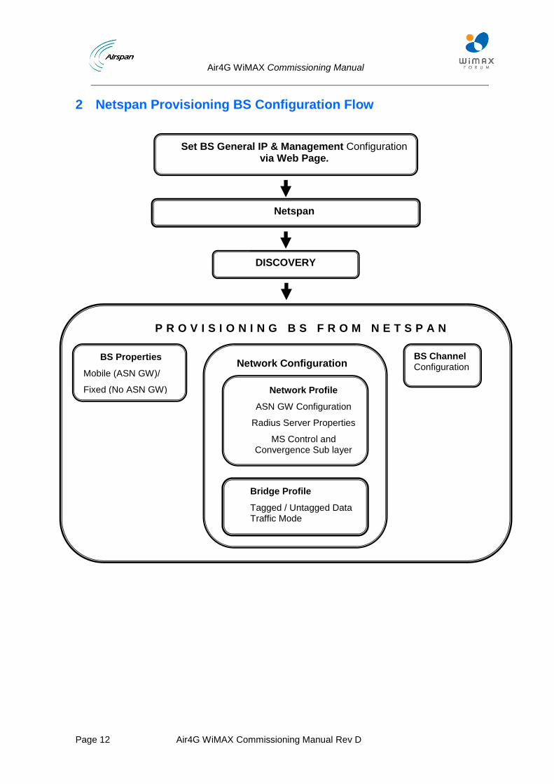
2 Netspan Provisioning BS Configuration Flow
Set BS General IP & Management Configuration via Web Page.
Netspan
DISCOVERY
P R O V I S I O N I N G B S F R O M N E T S P A N
Network Configuration
Network Profile
ASN GW Configuration
Radius Server Properties
MS Control and Convergence Sub layer
Bridge Profile
Tagged / Untagged Data Traffic Mode
BS Properties
Mobile (ASN GW)/
Fixed (No ASN GW)
BS Channel Configuration
Air4G WiMAX Commissioning Manual
Page 13 Air4G WiMAX Commissioning Manual Rev D
3 Set BS Management IP & BSID via Web Page
The following are the steps to access the BS via its WEB interface.
Wait for the BS to totally complete the boot sequence!
Ensure that your Web browser with which you want to access the Web-based Management is active.
To connect to Air4G via the WEB interface:
1. Open web browser ant type the BS address.
IP address – 192.168.0.100 (255.0.0.0) User name – Air4Gweb Password – thhr49Key
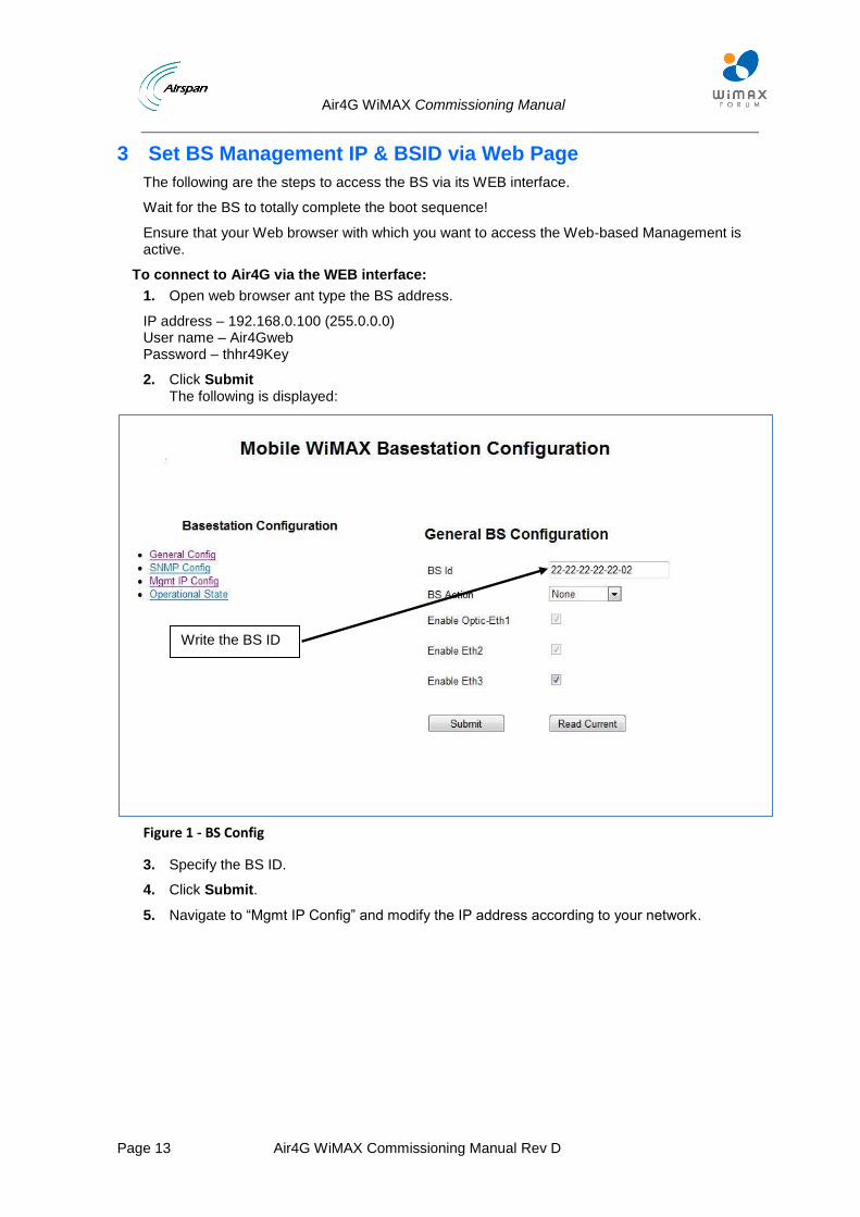
2. Click Submit The following is displayed:
Figure 1 - BS Config
3. Specify the BS ID.
4. Click Submit.
5. Navigate to “Mgmt IP Config” and modify the IP address according to your network.
Write the BS ID
Air4G WiMAX Commissioning Manual
Page 14 Air4G WiMAX Commissioning Manual Rev D
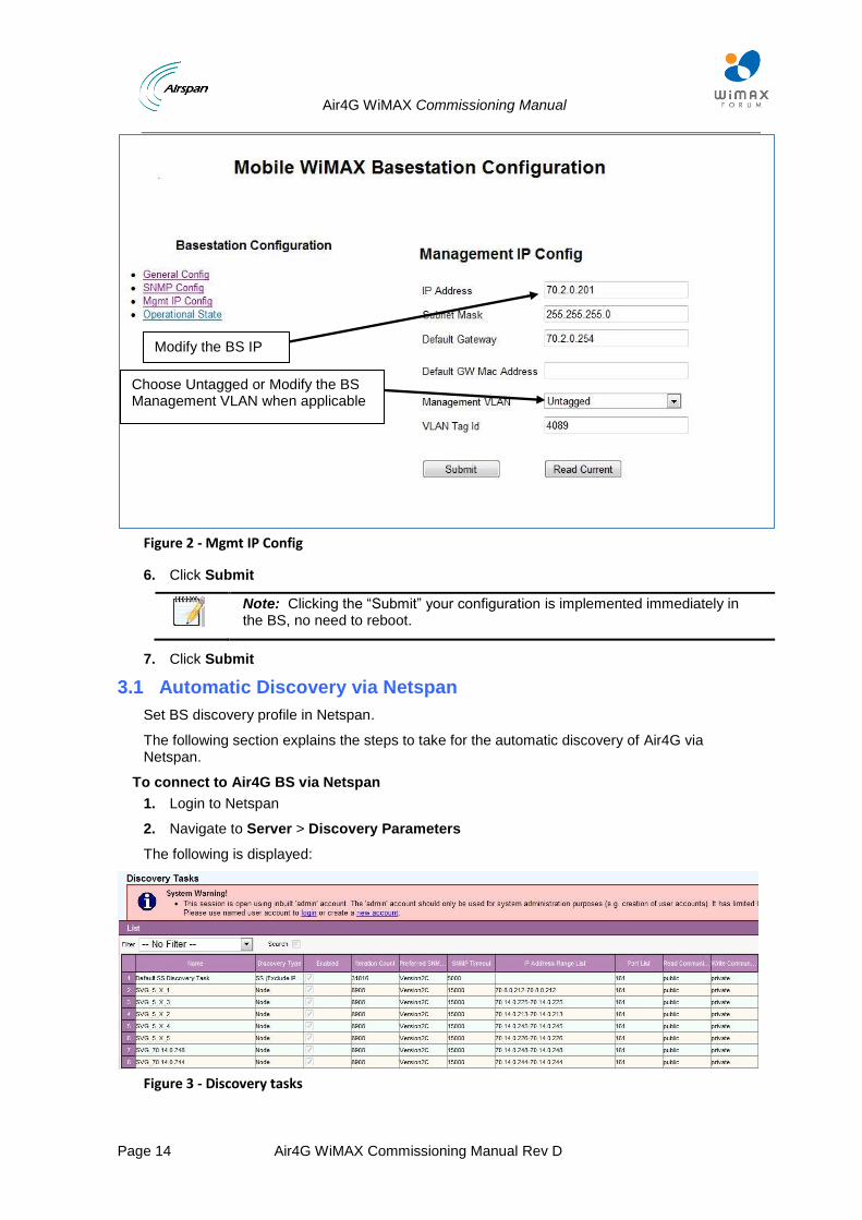
Figure 2 - Mgmt IP Config
6. Click Submit
Note: Clicking the “Submit” your configuration is implemented immediately in the BS, no need to reboot.
7. Click Submit
3.1 Automatic Discovery via Netspan
Set BS discovery profile in Netspan.
The following section explains the steps to take for the automatic discovery of Air4G via Netspan.
To connect to Air4G BS via Netspan
1. Login to Netspan
2. Navigate to Server > Discovery Parameters
The following is displayed:
Figure 3 - Discovery tasks
Modify the BS IP IPIP
Choose Untagged or Modify the BS Management VLAN when applicable
Air4G WiMAX Commissioning Manual
Page 15 Air4G WiMAX Commissioning Manual Rev D
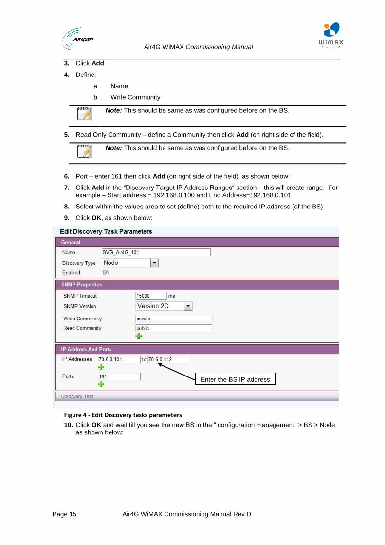
3. Click Add
4. Define:
a. Name
b. Write Community
Note: This should be same as was configured before on the BS.
5. Read Only Community – define a Community then click Add (on right side of the field).
Note: This should be same as was configured before on the BS.
6. Port – enter 161 then click Add (on right side of the field), as shown below:
7. Click Add in the “Discovery Target IP Address Ranges“ section – this will create range. For example – Start address = 192.168.0.100 and End Address=192.168.0.101
8. Select within the values area to set (define) both to the required IP address (of the BS)
9. Click OK, as shown below:
Figure 4 - Edit Discovery tasks parameters
10. Click OK and wait till you see the new BS in the “ configuration management > BS > Node, as shown below:
Enter the BS IP address
Air4G WiMAX Commissioning Manual
Page 16 Air4G WiMAX Commissioning Manual Rev D
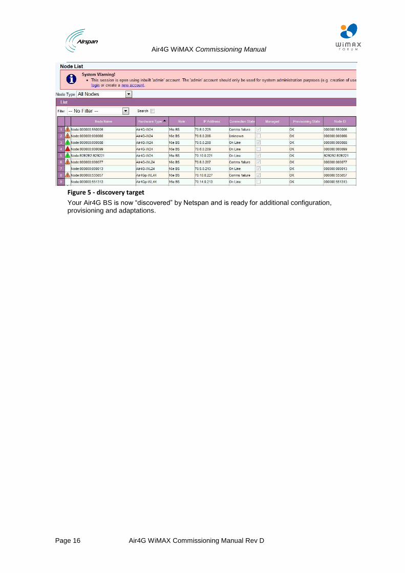
Figure 5 - discovery target
Your Air4G BS is now “discovered” by Netspan and is ready for additional configuration, provisioning and adaptations.
Air4G WiMAX Commissioning Manual
Page 17 Air4G WiMAX Commissioning Manual Rev D
4 Setup of BS Common Profiles
In this section Netspan profiles that are common to all working scenarios will be described.
All profiles are located under the “provisioning“ tab in the Node.
MGMT profile – Node profile
VoIP profile – Node profile
RF profile – channel profile
MCS profile – channel profile
PHY profile – channel profile
Air4G WiMAX Commissioning Manual
Page 18 Air4G WiMAX Commissioning Manual Rev D
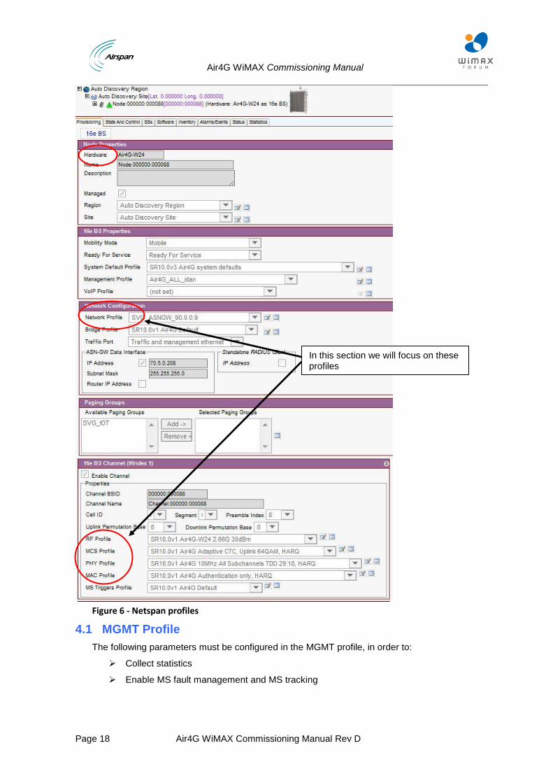
Figure 6 - Netspan profiles
4.1 MGMT Profile
The following parameters must be configured in the MGMT profile, in order to:
Collect statistics
Enable MS fault management and MS tracking
In this section we will focus on these profiles
Air4G WiMAX Commissioning Manual
Page 19 Air4G WiMAX Commissioning Manual Rev D
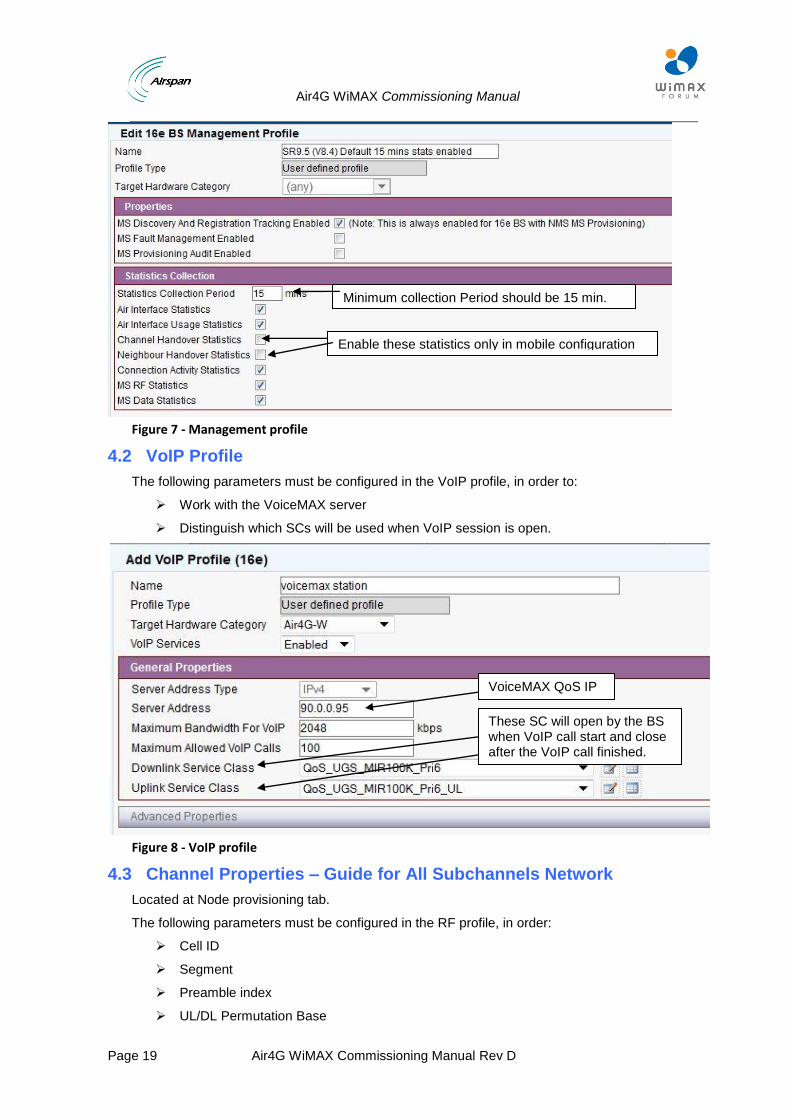
Figure 7 - Management profile
4.2 VoIP Profile
The following parameters must be configured in the VoIP profile, in order to:
Work with the VoiceMAX server
Distinguish which SCs will be used when VoIP session is open.
Figure 8 - VoIP profile
4.3 Channel Properties – Guide for All Subchannels Network
Located at Node provisioning tab.
The following parameters must be configured in the RF profile, in order:
Cell ID
Segment
Preamble index
UL/DL Permutation Base
VoiceMAX QoS IP
These SC will open by the BS when VoIP call start and close after the VoIP call finished.
Enable these statistics only in mobile configuration
Minimum collection Period should be 15 min.
Air4G WiMAX Commissioning Manual
Page 20 Air4G WiMAX Commissioning Manual Rev D
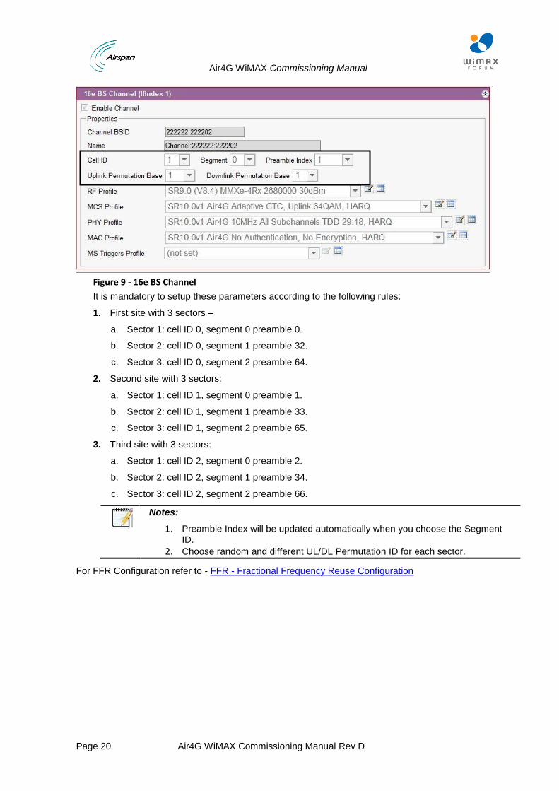
Figure 9 - 16e BS Channel
It is mandatory to setup these parameters according to the following rules:
1. First site with 3 sectors –
a. Sector 1: cell ID 0, segment 0 preamble 0.
b. Sector 2: cell ID 0, segment 1 preamble 32.
c. Sector 3: cell ID 0, segment 2 preamble 64.
2. Second site with 3 sectors:
a. Sector 1: cell ID 1, segment 0 preamble 1.
b. Sector 2: cell ID 1, segment 1 preamble 33.
c. Sector 3: cell ID 1, segment 2 preamble 65.
3. Third site with 3 sectors:
a. Sector 1: cell ID 2, segment 0 preamble 2.
b. Sector 2: cell ID 2, segment 1 preamble 34.
c. Sector 3: cell ID 2, segment 2 preamble 66.
Notes:
1. Preamble Index will be updated automatically when you choose the Segment ID.
2. Choose random and different UL/DL Permutation ID for each sector.
For FFR Configuration refer to - FFR - Fractional Frequency Reuse Configuration
Air4G WiMAX Commissioning Manual
Page 21 Air4G WiMAX Commissioning Manual Rev D
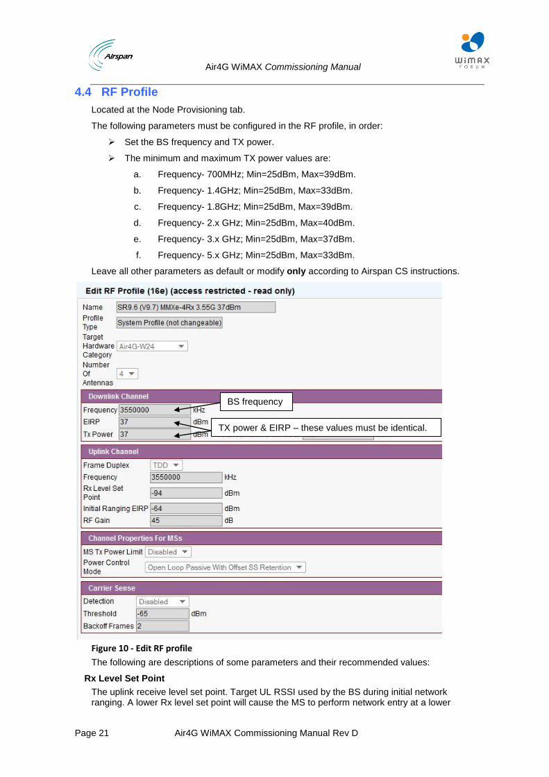
4.4 RF Profile
Located at the Node Provisioning tab.
The following parameters must be configured in the RF profile, in order:
Set the BS frequency and TX power.
The minimum and maximum TX power values are:
a. Frequency- 700MHz; Min=25dBm, Max=39dBm.
b. Frequency- 1.4GHz; Min=25dBm, Max=33dBm.
c. Frequency- 1.8GHz; Min=25dBm, Max=39dBm.
d. Frequency- 2.x GHz; Min=25dBm, Max=40dBm.
e. Frequency- 3.x GHz; Min=25dBm, Max=37dBm.
f. Frequency- 5.x GHz; Min=25dBm, Max=33dBm.
Leave all other parameters as default or modify only according to Airspan CS instructions.
Figure 10 - Edit RF profile
The following are descriptions of some parameters and their recommended values:
Rx Level Set Point
The uplink receive level set point. Target UL RSSI used by the BS during initial network ranging. A lower Rx level set point will cause the MS to perform network entry at a lower
BS frequency
TX power & EIRP – these values must be identical.
Air4G WiMAX Commissioning Manual
Page 22 Air4G WiMAX Commissioning Manual Rev D
received signal strength on the UL and vice versa when setting higher Rx level set point. Too high a set point will result in excess interference level to other cells; too low a set point will limit the cell range. Recommended values: Min = -110, Max = 50, Default = -94 dBm
Initial Ranging EIRP
Maximum equivalent isotropic received power at the BS during initial ranging. Used by MS to calculate initial entry range transmission power during Network entry.
Recommended values: Min = -130, Max = -40, Default = -64 dBm.
RF Gain
Indicates the gain of the RF stages of the sector. Higher RF gain > UL RSSI + noise level. This value is used in the RSSI calculations. Lower RF gain will decrease the level of UL signal strength and the level of UL noise and higher RF gain will do the opposite. Too low a RF gain will bring the signal close to the modem quantization noise and will decrease coverage. Too high RF gain will bring the signal closer to the saturation level of the modem and will increase the minimum distance required between MS and BS for proper operation.
Recommended values: Min = 30, Max = 50, Default = 45 dB.
Power Control Mode
Closed Loop – MS Tx power is exclusively controlled by the BS command.
Open Loop – MS Tx power is adjusted based on changes in the DL signal strength and BS command.
Recommended value: Open loop Passive with offset SS Retention.
4.5 MCS Profile
Located at the Node provisioning tab.
In the MCS profile the user can configure all modulations supported by the BS on both DL and UL.
It is highly recommended to use the latest MCS system profile, found in Netspan.
Air4G WiMAX Commissioning Manual
Page 23 Air4G WiMAX Commissioning Manual Rev D
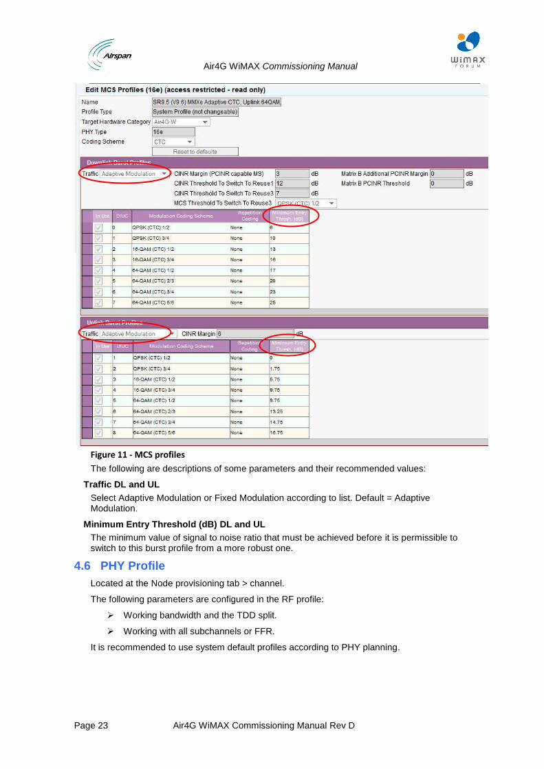
Figure 11 - MCS profiles
The following are descriptions of some parameters and their recommended values:
Traffic DL and UL
Select Adaptive Modulation or Fixed Modulation according to list. Default = Adaptive Modulation.
Minimum Entry Threshold (dB) DL and UL
The minimum value of signal to noise ratio that must be achieved before it is permissible to switch to this burst profile from a more robust one.
4.6 PHY Profile
Located at the Node provisioning tab > channel.
The following parameters are configured in the RF profile:
Working bandwidth and the TDD split.
Working with all subchannels or FFR.
It is recommended to use system default profiles according to PHY planning.
Air4G WiMAX Commissioning Manual
Page 24 Air4G WiMAX Commissioning Manual Rev D
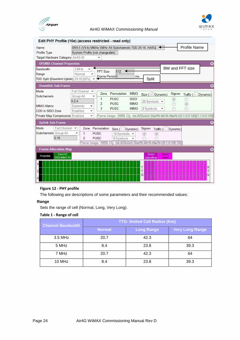
Figure 12 - PHY profile
The following are descriptions of some parameters and their recommended values:
Range
Sets the range of cell (Normal, Long, Very Long).
Table 1 - Range of cell
Channel Bandwidth TTG- limited Cell Radius (Km)
Normal Long Range Very Long Range
3.5 MHz 20.7 42.3 64
5 MHz 8.4 23.8 39.3
7 MHz 20.7 42.3 64
10 MHz 8.4 23.8 39.3
Profile Name
BW and FFT size
Split
Air4G WiMAX Commissioning Manual
Page 25 Air4G WiMAX Commissioning Manual Rev D
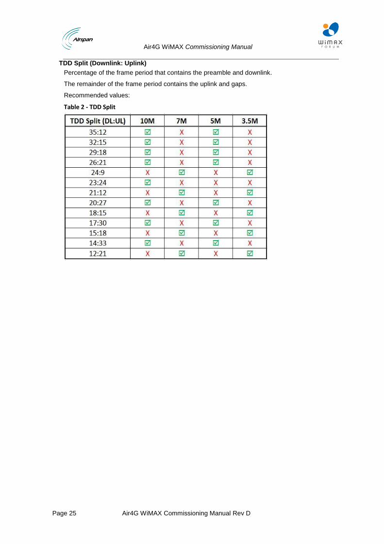
TDD Split (Downlink: Uplink)
Percentage of the frame period that contains the preamble and downlink.
The remainder of the frame period contains the uplink and gaps.
Recommended values:
Table 2 - TDD Split
Air4G WiMAX Commissioning Manual
Page 26 Air4G WiMAX Commissioning Manual Rev D
5 WiMAX Network Architectures Setup
This section refers to the supported Network Architecture for Air4G WiMAX BS, based on
802.16e BS Network Architecture.
This section describes the setup configuration regarding to the Network Profile and Network
Interfaces (Bridge Profile (VLAN Tagged / untagged), ASN GW, Radius) within Netspan.
(It does not refer in detail to RF and system configuration profile).
5.1 Standalone, No Authentication, No ASN-GW
In this architecture the Air4G WiMAX BS is connected directly to the CSN. This architecture does not include an ASN Gateway and AAA server.
The following applies in the stand alone network architecture:
Data service flows between the BS and CPEs are Ethernet CS only.
All traffic between the CPEs and the CSN network is passing through the BS directly. Traffic is L2 (including Ethernet header and VLANs) since all data service flows are Ethernet CS only.
Network entry process of the CPEs includes only the BS.
No CPE authentication is available. AES Encryption of the data service flows in the WiMAX air interface between the BS and the CPE using PKMv2 is not applicable.
The CPEs are managed by Netspan. Data service flows to the CPEs are provisioned by Netspan using service products.
Mobile features of handover and idle mode are not applicable.
Air4G WiMAX Commissioning Manual
Page 27 Air4G WiMAX Commissioning Manual Rev D
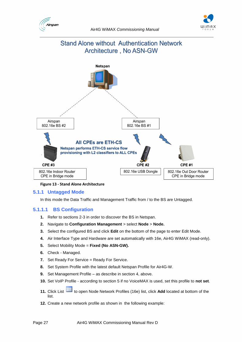
Figure 13 - Stand Alone Architecture
5.1.1 Untagged Mode
In this mode the Data Traffic and Management Traffic from / to the BS are Untagged.
5.1.1.1 BS Configuration
1. Refer to sections 2-3 in order to discover the BS in Netspan.
2. Navigate to Configuration Management > select Node > Node.
3. Select the configured BS and click Edit on the bottom of the page to enter Edit Mode.
4. Air Interface Type and Hardware are set automatically with 16e, Air4G WiMAX (read-only).
5. Select Mobility Mode = Fixed (No ASN-GW).
6. Check - Managed.
7. Set Ready For Service = Ready For Service.
8. Set System Profile with the latest default Netspan Profile for Air4G-W.
9. Set Management Profile – as describe in section 4, above.
10. Set VoIP Profile - according to section 5 if no VoiceMAX is used, set this profile to not set.
11. Click List to open Node Network Profiles (16e) list, click Add located at bottom of the list.
12. Create a new network profile as shown in the following example:
Air4G WiMAX Commissioning Manual
Page 28 Air4G WiMAX Commissioning Manual Rev D
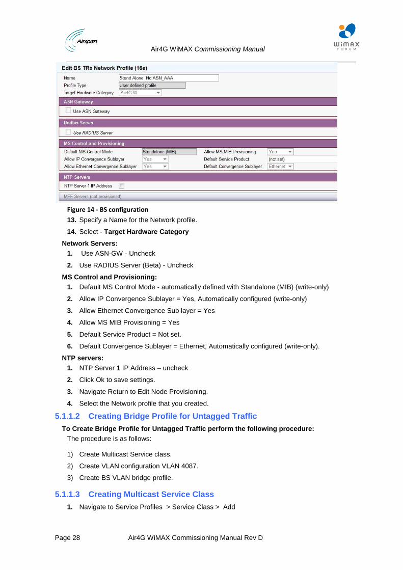
Figure 14 - BS configuration
13. Specify a Name for the Network profile.
14. Select - Target Hardware Category
Network Servers:
1. Use ASN-GW - Uncheck
2. Use RADIUS Server (Beta) - Uncheck
MS Control and Provisioning:
1. Default MS Control Mode - automatically defined with Standalone (MIB) (write-only)
2. Allow IP Convergence Sublayer = Yes, Automatically configured (write-only)
3. Allow Ethernet Convergence Sub layer = Yes
4. Allow MS MIB Provisioning = Yes
5. Default Service Product = Not set.
6. Default Convergence Sublayer = Ethernet, Automatically configured (write-only).
NTP servers:
1. NTP Server 1 IP Address – uncheck
2. Click Ok to save settings.
3. Navigate Return to Edit Node Provisioning.
4. Select the Network profile that you created.
5.1.1.2 Creating Bridge Profile for Untagged Traffic
To Create Bridge Profile for Untagged Traffic perform the following procedure:
The procedure is as follows:
1) Create Multicast Service class.
2) Create VLAN configuration VLAN 4087.
3) Create BS VLAN bridge profile.
5.1.1.3 Creating Multicast Service Class
1. Navigate to Service Profiles > Service Class > Add
Air4G WiMAX Commissioning Manual
Page 29 Air4G WiMAX Commissioning Manual Rev D
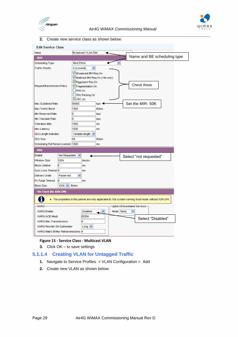
2. Create new service class as shown below:
Figure 15 - Service Class - Multicast VLAN
3. Click OK – to save settings
5.1.1.4 Creating VLAN for Untagged Traffic
1. Navigate to Service Profiles > VLAN Configuration > Add
2. Create new VLAN as shown below:
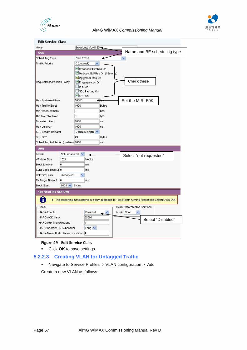
Name and BE scheduling type
Set the MIR- 50K
Select “Disabled”
Select “not requested”
Check these parameters
Air4G WiMAX Commissioning Manual
Page 30 Air4G WiMAX Commissioning Manual Rev D
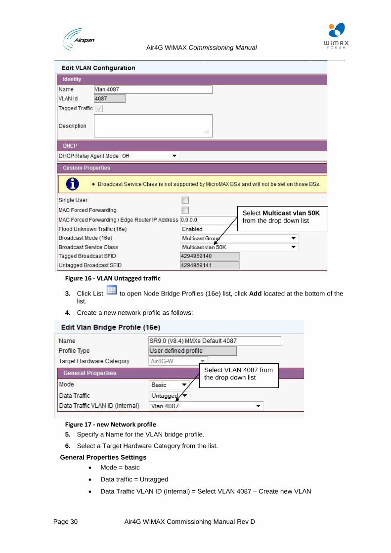
Figure 16 - VLAN Untagged traffic
3. Click List to open Node Bridge Profiles (16e) list, click Add located at the bottom of the list.
4. Create a new network profile as follows:
Figure 17 - new Network profile
5. Specify a Name for the VLAN bridge profile.
6. Select a Target Hardware Category from the list.
General Properties Settings
Mode = basic
Data traffic = Untagged
Data Traffic VLAN ID (Internal) = Select VLAN 4087 – Create new VLAN
Select Multicast vlan 50K from the drop down list
Select VLAN 4087 from the drop down list
Air4G WiMAX Commissioning Manual
Page 31 Air4G WiMAX Commissioning Manual Rev D
7. Click Ok to save settings.
Set traffic port = Traffic and Management Ethernet.
Set IP address and Subnet mask according to BS configuration as configured on the BS management web page.
5.1.1.5 Set Channel Properties:
1. Check Enable channel and set RF Properties and characteristics according BS HW and RF requirement – see section 7.
2. Set the Suitable MCS profile – see section 8.
3. Set the Suitable PHY profile – see section 9.
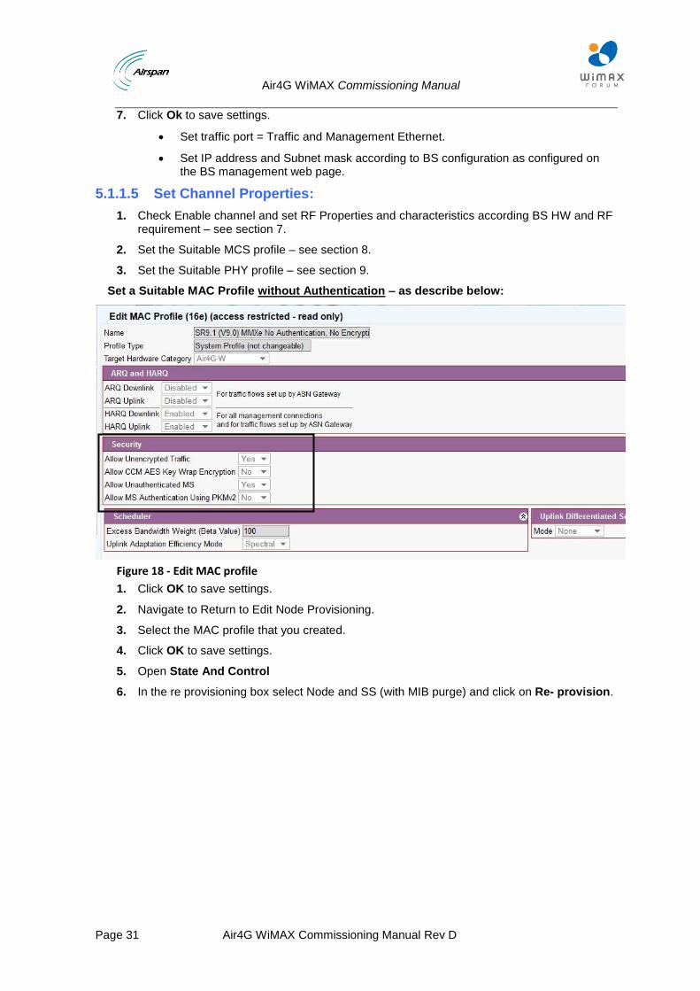
Set a Suitable MAC Profile without Authentication – as describe below:
Figure 18 - Edit MAC profile
1. Click OK to save settings.
2. Navigate to Return to Edit Node Provisioning.
3. Select the MAC profile that you created.
4. Click OK to save settings.
5. Open State And Control
6. In the re provisioning box select Node and SS (with MIB purge) and click on Re- provision.
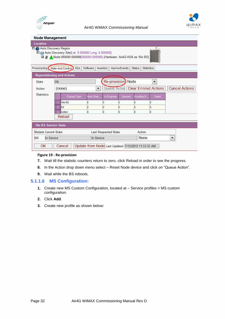
Air4G WiMAX Commissioning Manual
Page 32 Air4G WiMAX Commissioning Manual Rev D
Figure 19 - Re-provision
7. Wait till the statistic counters return to zero, click Reload in order to see the progress.
8. In the Action drop down menu select – Reset Node device and click on “Queue Action”.
9. Wait while the BS reboots.
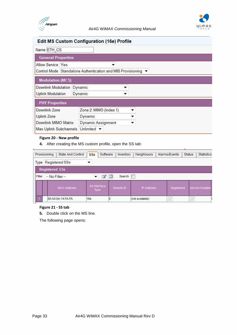
5.1.1.6 MS Configuration:
1. Create new MS Custom Configuration, located at – Service profiles > MS custom configuration.
2. Click Add.
3. Create new profile as shown below:
Air4G WiMAX Commissioning Manual
Page 33 Air4G WiMAX Commissioning Manual Rev D
Figure 20 - New profile
4. After creating the MS custom profile, open the SS tab:
Figure 21 - SS tab
5. Double click on the MS line.
The following page opens:
Air4G WiMAX Commissioning Manual
Page 34 Air4G WiMAX Commissioning Manual Rev D
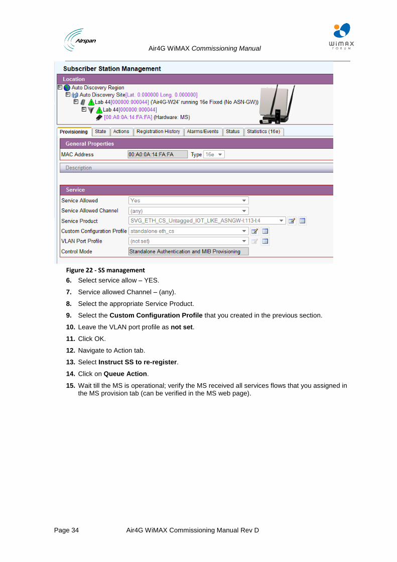
Figure 22 - SS management
6. Select service allow – YES.
7. Service allowed Channel – (any).
8. Select the appropriate Service Product.
9. Select the Custom Configuration Profile that you created in the previous section.
10. Leave the VLAN port profile as not set.
11. Click OK.
12. Navigate to Action tab.
13. Select Instruct SS to re-register.
14. Click on Queue Action.
15. Wait till the MS is operational; verify the MS received all services flows that you assigned in the MS provision tab (can be verified in the MS web page).
Air4G WiMAX Commissioning Manual
Page 35 Air4G WiMAX Commissioning Manual Rev D
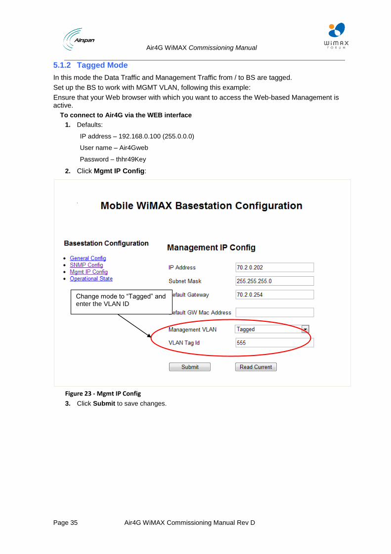
5.1.2 Tagged Mode
In this mode the Data Traffic and Management Traffic from / to BS are tagged.
Set up the BS to work with MGMT VLAN, following this example:
Ensure that your Web browser with which you want to access the Web-based Management is active.
To connect to Air4G via the WEB interface
1. Defaults:
IP address – 192.168.0.100 (255.0.0.0)
User name – Air4Gweb
Password – thhr49Key
2. Click Mgmt IP Config:
Figure 23 - Mgmt IP Config
3. Click Submit to save changes.
Change mode to “Tagged” and enter the VLAN ID
Air4G WiMAX Commissioning Manual
Page 36 Air4G WiMAX Commissioning Manual Rev D
VLAN configuration in Netspan.
Create VLAN configuration for any VLAN.
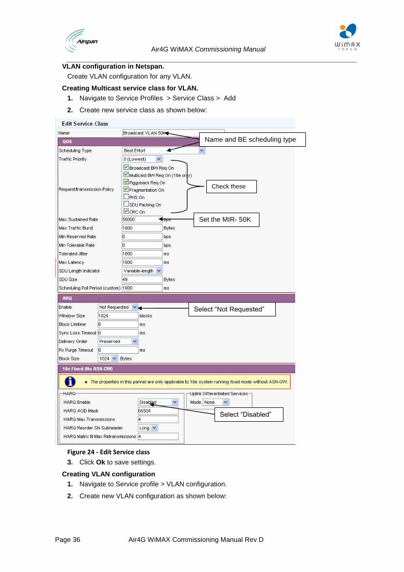
Creating Multicast service class for VLAN.
1. Navigate to Service Profiles > Service Class > Add
2. Create new service class as shown below:
Figure 24 - Edit Service class
3. Click Ok to save settings.
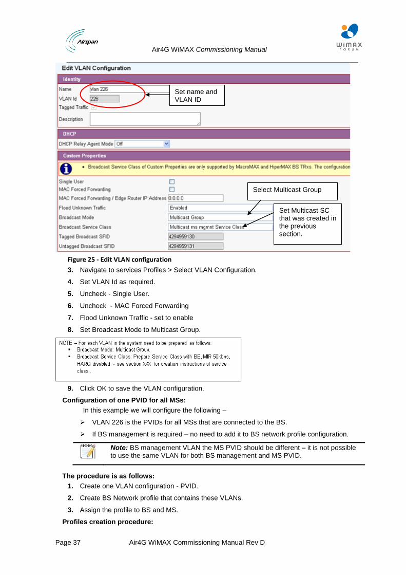
Creating VLAN configuration
1. Navigate to Service profile > VLAN configuration.
2. Create new VLAN configuration as shown below:
Check these parameters
Name and BE scheduling type
Set the MIR- 50K
Select “Disabled”
Select “Not Requested”
Air4G WiMAX Commissioning Manual
Page 37 Air4G WiMAX Commissioning Manual Rev D
Figure 25 - Edit VLAN configuration
3. Navigate to services Profiles > Select VLAN Configuration.
4. Set VLAN Id as required.
5. Uncheck - Single User.
6. Uncheck - MAC Forced Forwarding
7. Flood Unknown Traffic - set to enable
8. Set Broadcast Mode to Multicast Group.
9. Click OK to save the VLAN configuration.
Configuration of one PVID for all MSs:
In this example we will configure the following –
VLAN 226 is the PVIDs for all MSs that are connected to the BS.
If BS management is required – no need to add it to BS network profile configuration.
Note: BS management VLAN the MS PVID should be different – it is not possible to use the same VLAN for both BS management and MS PVID.
The procedure is as follows:
1. Create one VLAN configuration - PVID.
2. Create BS Network profile that contains these VLANs.
3. Assign the profile to BS and MS.
Profiles creation procedure:
Set name and VLAN ID
Select Multicast Group
Set Multicast SC that was created in the previous section.
Air4G WiMAX Commissioning Manual
Page 38 Air4G WiMAX Commissioning Manual Rev D
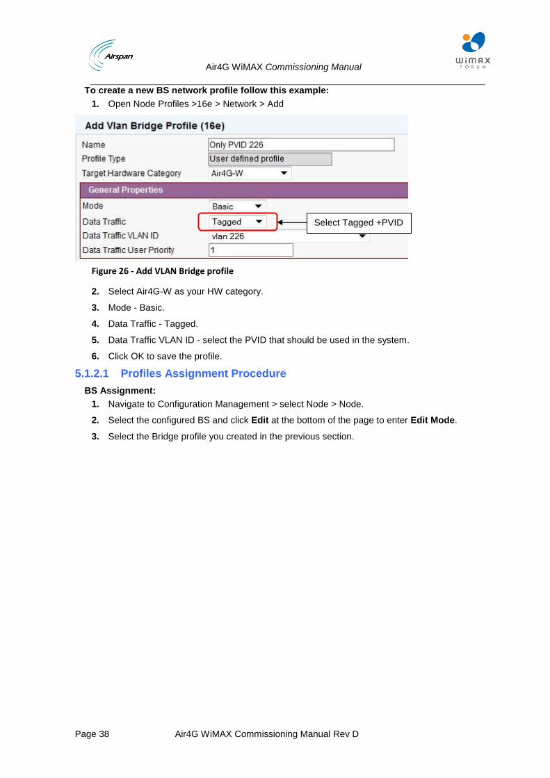
To create a new BS network profile follow this example:
1. Open Node Profiles >16e > Network > Add
Figure 26 - Add VLAN Bridge profile
2. Select Air4G-W as your HW category.
3. Mode - Basic.
4. Data Traffic - Tagged.
5. Data Traffic VLAN ID - select the PVID that should be used in the system.
6. Click OK to save the profile.
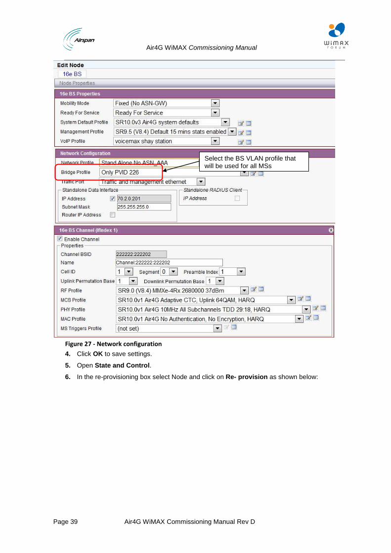
5.1.2.1 Profiles Assignment Procedure
BS Assignment:
1. Navigate to Configuration Management > select Node > Node.
2. Select the configured BS and click Edit at the bottom of the page to enter Edit Mode.
3. Select the Bridge profile you created in the previous section.
Select Tagged +PVID
Air4G WiMAX Commissioning Manual
Page 39 Air4G WiMAX Commissioning Manual Rev D
Figure 27 - Network configuration
4. Click OK to save settings.
5. Open State and Control.
6. In the re-provisioning box select Node and click on Re- provision as shown below:
Select the BS VLAN profile that will be used for all MSs
Air4G WiMAX Commissioning Manual
Page 40 Air4G WiMAX Commissioning Manual Rev D
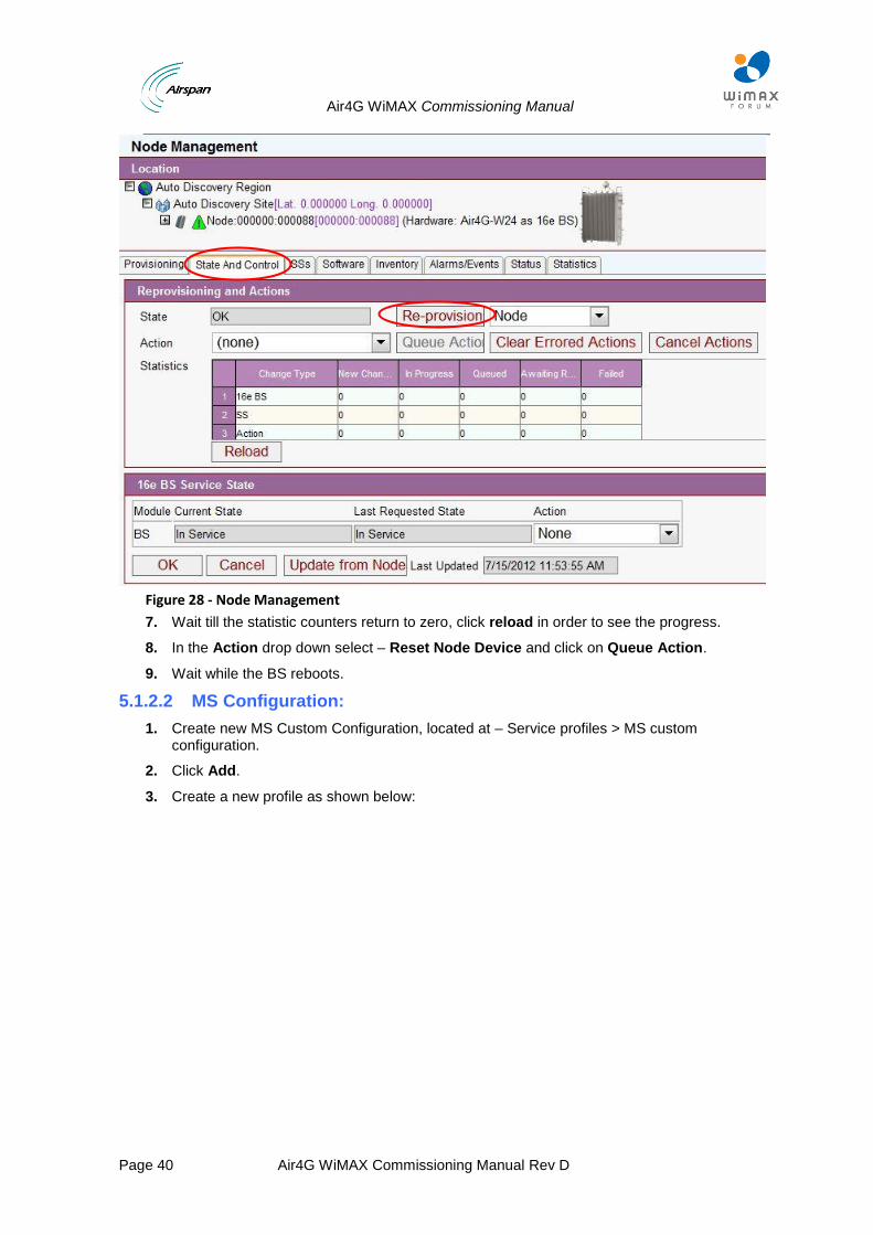
Figure 28 - Node Management
7. Wait till the statistic counters return to zero, click reload in order to see the progress.
8. In the Action drop down select – Reset Node Device and click on Queue Action.
9. Wait while the BS reboots.
5.1.2.2 MS Configuration:
1. Create new MS Custom Configuration, located at – Service profiles > MS custom configuration.
2. Click Add.
3. Create a new profile as shown below:

Air4G WiMAX Commissioning Manual
Page 41 Air4G WiMAX Commissioning Manual Rev D
Figure 29 - New profile
4. After creating the MS custom profile, open the SS tab:
Figure 30 - SS Tab tab
5. Double click on the MS line.
The following page opens:
Air4G WiMAX Commissioning Manual
Page 42 Air4G WiMAX Commissioning Manual Rev D
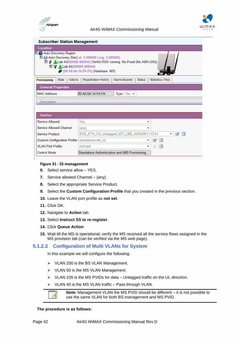
Figure 31 - SS management
6. Select service allow – YES.
7. Service allowed Channel – (any).
8. Select the appropriate Service Product.
9. Select the Custom Configuration Profile that you created in the previous section.
10. Leave the VLAN port profile as not set.
11. Click OK.
12. Navigate to Action tab.
13. Select Instruct SS to re-register.
14. Click Queue Action
15. Wait till the MS is operational, verify the MS received all the service flows assigned in the MS provision tab (can be verified via the MS web page).
5.1.2.3 Configuration of Multi VLANs for System
In this example we will configure the following:
VLAN 200 is the BS VLAN Management.
VLAN 50 is the MS VLAN Management.
VLAN 226 is the MS PVIDs for data – Untagged traffic on the UL direction.
VLAN 40 is the MS VLAN traffic – Pass through VLAN.
Note: Management VLAN the MS PVID should be different – it is not possible to use the same VLAN for both BS management and MS PVID.
The procedure is as follows:
Air4G WiMAX Commissioning Manual
Page 43 Air4G WiMAX Commissioning Manual Rev D
1. Create 4 different VLAN configurations for each VLAN used in the system – Management and PVID.
2. Create BD Network profile containing these VLANs.
3. Create SS VLAN port for MS.
4. Assign the profile to BS and MS.
5. Create 3 VLAN configurations as described previously:
Management VLAN for BS = 200
Management VLAN for MS = 50
VLAN ID (PVID) for MS = 226
VLAN ID (pass through) for MS = 40
Profiles Creation Procedure:
Create a new BS network profile as shown in the following this example:
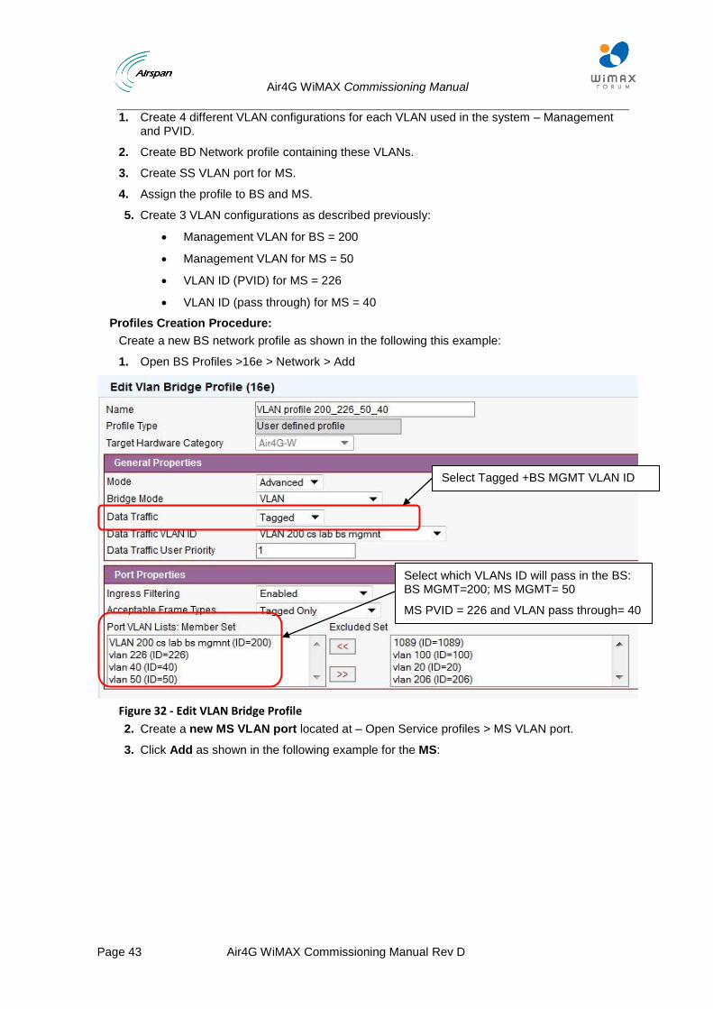
1. Open BS Profiles >16e > Network > Add
Figure 32 - Edit VLAN Bridge Profile
2. Create a new MS VLAN port located at – Open Service profiles > MS VLAN port.
3. Click Add as shown in the following example for the MS:
Select Tagged +BS MGMT VLAN ID
Select which VLANs ID will pass in the BS: BS MGMT=200; MS MGMT= 50
MS PVID = 226 and VLAN pass through= 40
Air4G WiMAX Commissioning Manual
Page 44 Air4G WiMAX Commissioning Manual Rev D
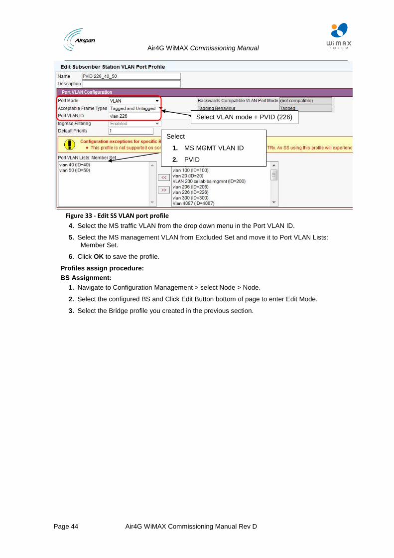
Figure 33 - Edit SS VLAN port profile
4. Select the MS traffic VLAN from the drop down menu in the Port VLAN ID.
5. Select the MS management VLAN from Excluded Set and move it to Port VLAN Lists: Member Set.
6. Click OK to save the profile.
Profiles assign procedure:
BS Assignment:
1. Navigate to Configuration Management > select Node > Node.
2. Select the configured BS and Click Edit Button bottom of page to enter Edit Mode.
3. Select the Bridge profile you created in the previous section.
Select VLAN mode + PVID (226)
Select
1. MS MGMT VLAN ID
2. PVID
Air4G WiMAX Commissioning Manual
Page 45 Air4G WiMAX Commissioning Manual Rev D
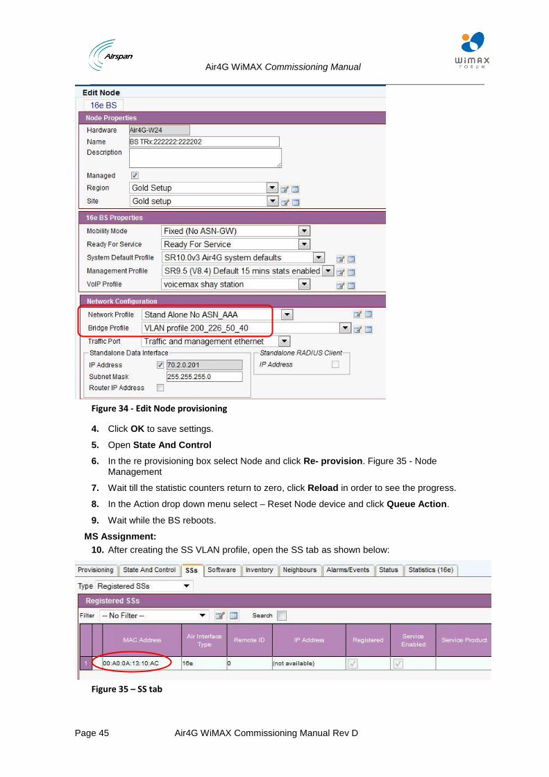
Figure 34 - Edit Node provisioning
4. Click OK to save settings.
5. Open State And Control
6. In the re provisioning box select Node and click Re- provision. Figure 35 - Node Management
7. Wait till the statistic counters return to zero, click Reload in order to see the progress.
8. In the Action drop down menu select – Reset Node device and click Queue Action.
9. Wait while the BS reboots.
MS Assignment:
10. After creating the SS VLAN profile, open the SS tab as shown below:
Figure 35 – SS tab
Air4G WiMAX Commissioning Manual
Page 46 Air4G WiMAX Commissioning Manual Rev D
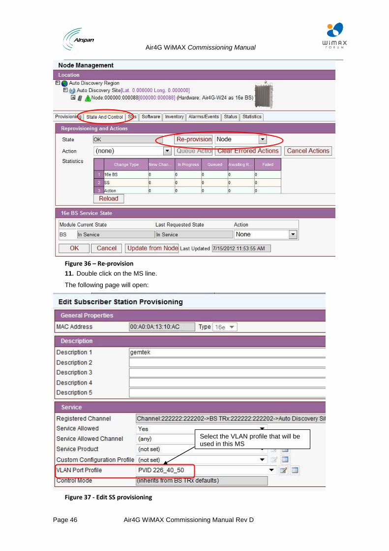
Figure 36 – Re-provision
11. Double click on the MS line.
The following page will open:
Figure 37 - Edit SS provisioning
Select the VLAN profile that will be used in this MS
Air4G WiMAX Commissioning Manual
Page 47 Air4G WiMAX Commissioning Manual Rev D
12. Service Allowed – YES.
13. Service Allowed Channel – (any).
14. Select the appropriate Service Product.
15. Select the Custom Configuration Profile that you created.
16. Select the proper SS VLAN profile that you created in the previous section in the VLAN PORT Profile.
17. Click OK.
18. Navigate to Action.
19. Select Instruct SS to Re-register.
20. Click Queue Action
21. Wait till the MS is operational; verify the MS received all service flows assigned in the MS provision tab (can be verified in the MS web page).
22. Used sections 2-3 in order to discover the BS in Netspan.
23. Navigate to Configuration Management > select Node > Node.
24. Select the configured BS and Click Edit Button bottom of page to enter Edit Mode.
25. Air Interface Type and Hardware are set automatically with 16e, Air4G WiMAXAir4G WiMAX(Read only).
26. Select Mobility Mode - Fixed (No ASN-GW).
27. Check - Managed.
28. Set Ready For Service - Ready For Service.
29. Set System Profile with a latest default Netspan Profile for MMXe.
30. Set Management Profile – as described above.
31. Set VoIP Profile - if no VoiceMAX is used, set this profile to not set.
32. Click List to open Node Network Profiles (16e) List, click Add located on bottom of the list.
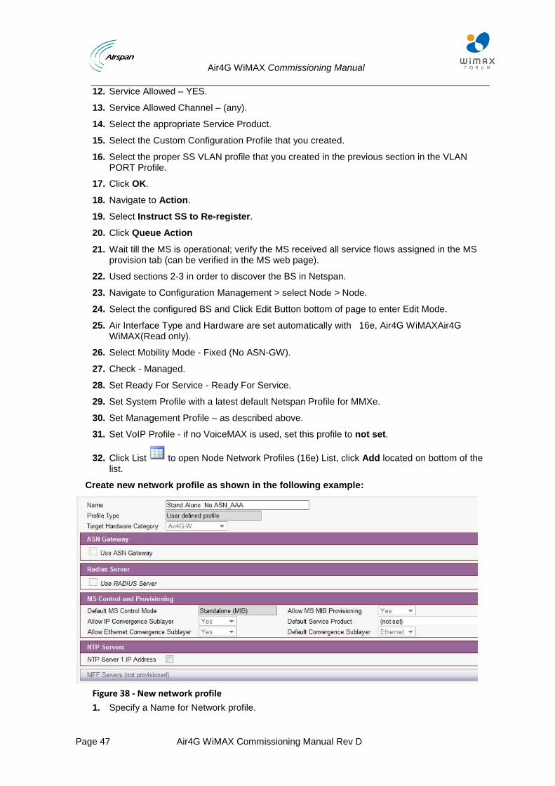
Create new network profile as shown in the following example:
Figure 38 - New network profile
1. Specify a Name for Network profile.
Air4G WiMAX Commissioning Manual
Page 48 Air4G WiMAX Commissioning Manual Rev D
2. Select Target Hardware Category.
Network Servers:
Uncheck Use ASN-GW.
Uncheck Use RADIUS Server (Beta).
MS Control and Provisioning:
Default MS Control Mode is automatically set to Standalone (MIB) (Read only).
Allow MS MIB Provisioning - YES
Set Default Service Product - (not set).
Default Convergence Sub layer - Ethernet (Automatically configured Read only).
Allow IP Convergence Sub layer - Yes (Automatically configured Read only).
Set Allow Ethernet Convergence Sub layer - Yes.
NTP Servers:
Uncheck NTP Server 1 IP Address.
3. Click OK to save settings.
4. Return to Edit Node Provisioning.
5. Select from list the Network profile previously created.
6. Select from list the bridge profile previously configured ( VLAN configuration).
7. Set traffic port = Traffic and management Ethernet.
8. Set IP address and Subnet mask according to BS configuration as configured on the BS management web page.
5.1.2.4 Set Channel Properties:
1. Check Enable channel and set RF Properties and characteristics according BS HW and RF requirement – as described above.
2. Set the Suitable MCS profile – as described above.
3. Set the Suitable PHY profile – as described above.
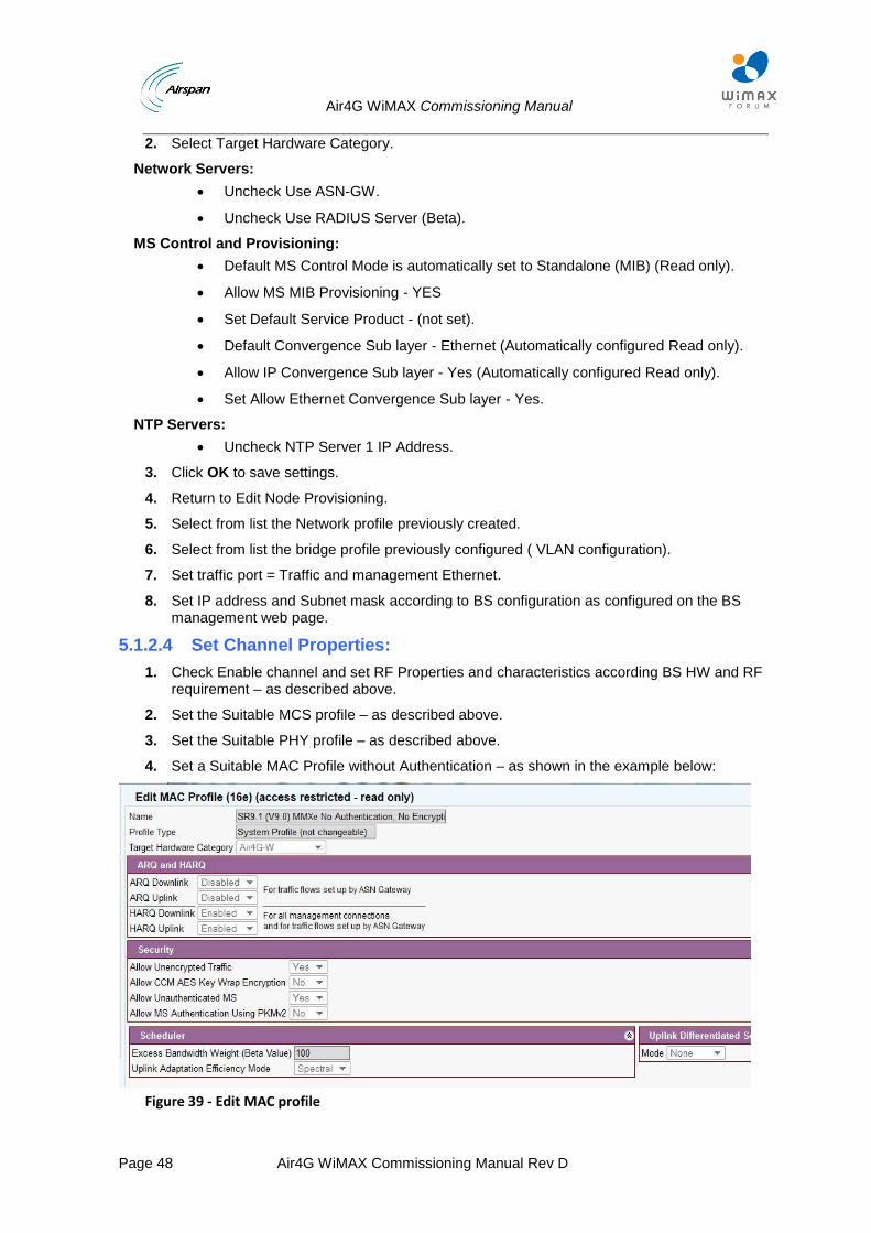
4. Set a Suitable MAC Profile without Authentication – as shown in the example below:
Figure 39 - Edit MAC profile
Air4G WiMAX Commissioning Manual
Page 49 Air4G WiMAX Commissioning Manual Rev D
5. Click OK to save settings.
6. Return to Edit Node Provisioning.
7. Select the MAC profile previously created.
8. Click OK
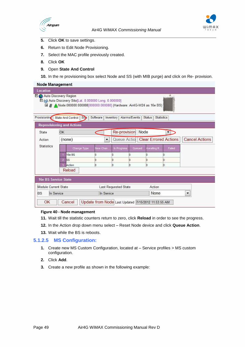
9. Open State And Control
10. In the re provisioning box select Node and SS (with MIB purge) and click on Re- provision.
Figure 40 - Node management
11. Wait till the statistic counters return to zero, click Reload in order to see the progress.
12. In the Action drop down menu select – Reset Node device and click Queue Action.
13. Wait while the BS is reboots.
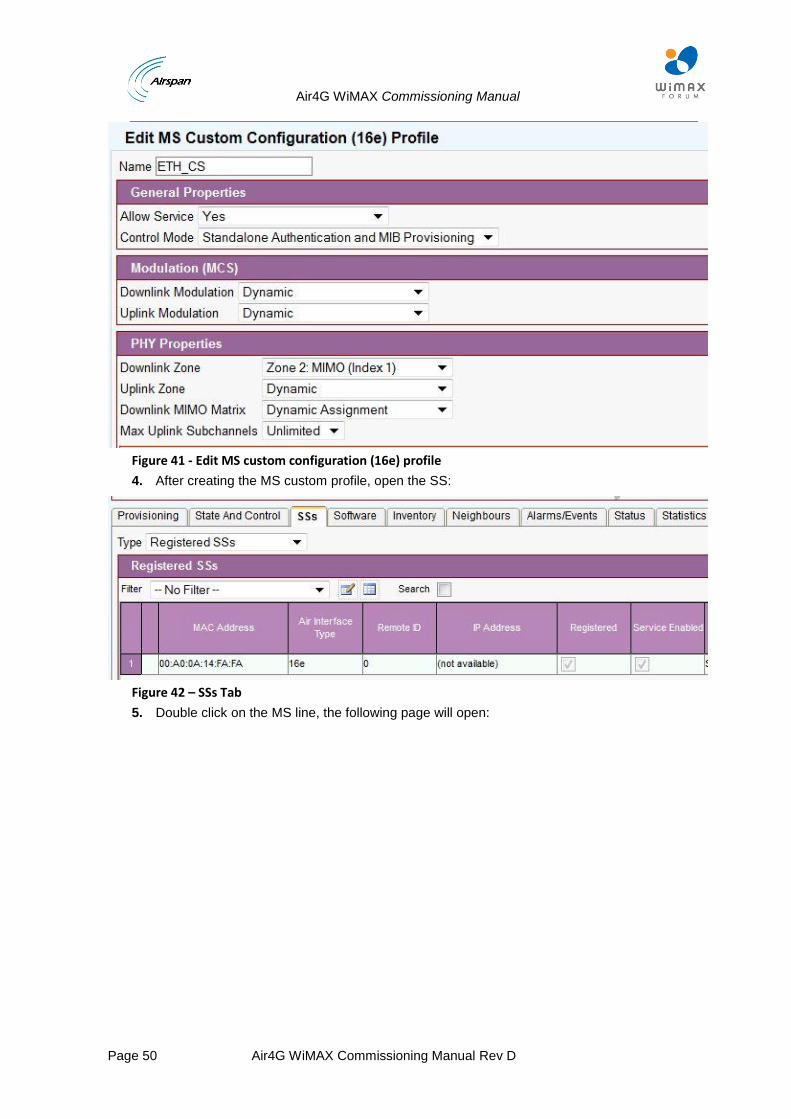
5.1.2.5 MS Configuration:
1. Create new MS Custom Configuration, located at – Service profiles > MS custom configuration.
2. Click Add.
3. Create a new profile as shown in the following example:
Air4G WiMAX Commissioning Manual
Page 50 Air4G WiMAX Commissioning Manual Rev D
Figure 41 - Edit MS custom configuration (16e) profile
4. After creating the MS custom profile, open the SS:
Figure 42 – SSs Tab
5. Double click on the MS line, the following page will open:
Air4G WiMAX Commissioning Manual
Page 51 Air4G WiMAX Commissioning Manual Rev D
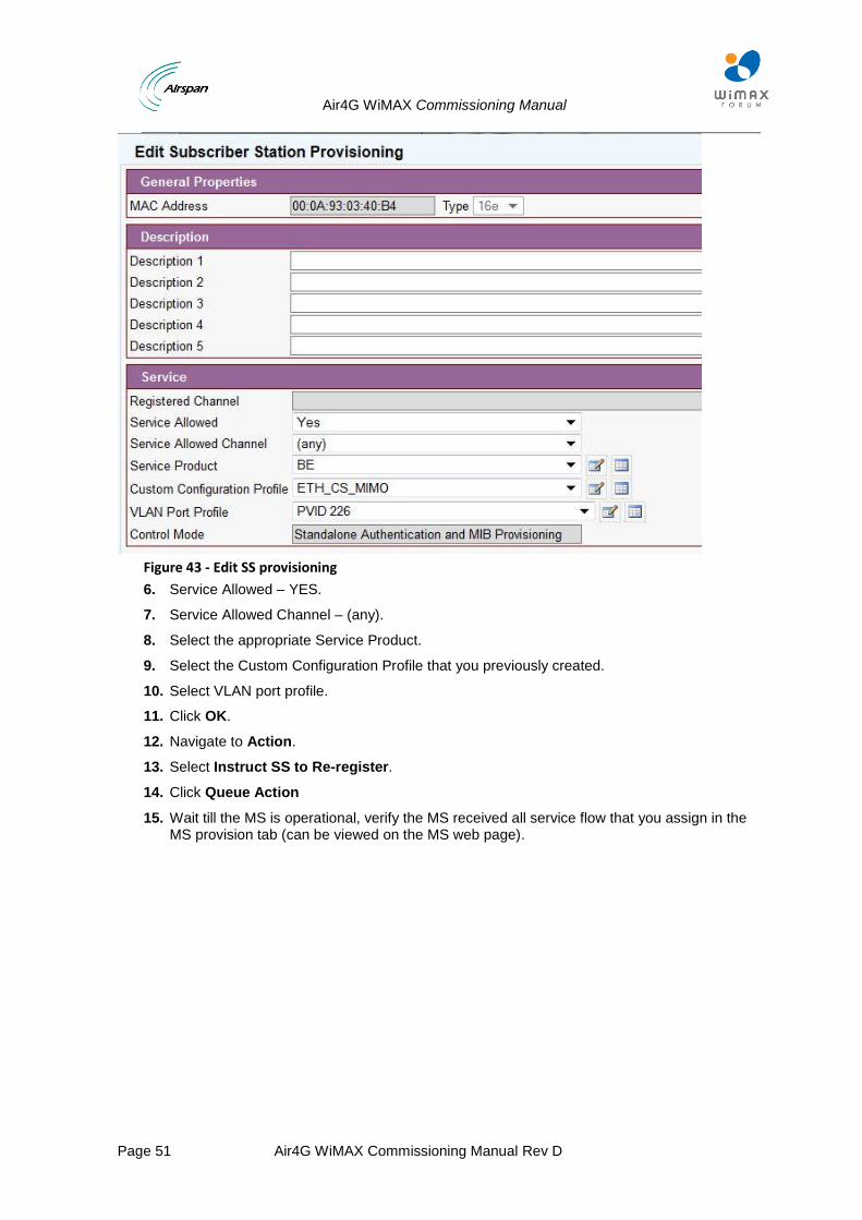
Figure 43 - Edit SS provisioning
6. Service Allowed – YES.
7. Service Allowed Channel – (any).
8. Select the appropriate Service Product.
9. Select the Custom Configuration Profile that you previously created.
10. Select VLAN port profile.
11. Click OK.
12. Navigate to Action.
13. Select Instruct SS to Re-register.
14. Click Queue Action
15. Wait till the MS is operational, verify the MS received all service flow that you assign in the MS provision tab (can be viewed on the MS web page).
Air4G WiMAX Commissioning Manual
Page 52 Air4G WiMAX Commissioning Manual Rev D
5.2 Standalone + Authentication (Airspan Free Radius AAA server) + Netspan Provisioning
In this architecture the Air4G BS is connected directly to the CSN. This architecture does not include an ASN Gateway.
The following applies in the stand alone network architecture:
Data service flows between the BS and CPEs are Ethernet CS only.
All traffic between the CPEs and the CSN network is passing through the BS directly. Traffic is L2 (including Ethernet header and VLANs) since all data service flows are Ethernet CS only.
Network entry process of the MS includes the BS and AAA server for MS authentication.
AES Encryption of the data service flows in the WiMAX air interface between the BS and the MS using PKMv2 is applicable as the BS derives encryption keys from the AAA server.
The CPEs are managed by Netspan. Data service flows to the CPEs are provisioned by Netspan using service products.
Mobile features of handover and idle mode are not applicable.
The Free radius installation is described in the document - UGD-D00209_Getting_Started with_the_ AAA_Server_SR10_2_RevF
Air4G WiMAX Commissioning Manual
Page 53 Air4G WiMAX Commissioning Manual Rev D
5.2.1 Netspan Configuration of Airspan’s FreeRADIUS
Note: Netspan requires a suitable license when managing the FreeRADIUS AAA.
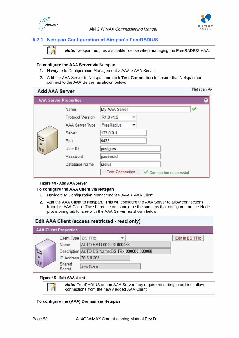
To configure the AAA Server via Netspan
1. Navigate to Configuration Management > AAA > AAA Server.
2. Add the AAA Server to Netspan and click Test Connection to ensure that Netspan can connect to the AAA Server, as shown below:
Figure 44 - Add AAA Server
To configure the AAA Client via Netspan
1. Navigate to Configuration Management > AAA > AAA Client.
2. Add the AAA Client to Netspan. This will configure the AAA Server to allow connections from this AAA Client. The shared secret should be the same as that configured on the Node provisioning tab for use with the AAA Server, as shown below:
Figure 45 - Edit AAA client
Note: FreeRADIUS on the AAA Server may require restarting in order to allow connections from the newly added AAA Client.
To configure the (AAA) Domain via Netspan
Air4G WiMAX Commissioning Manual
Page 54 Air4G WiMAX Commissioning Manual Rev D
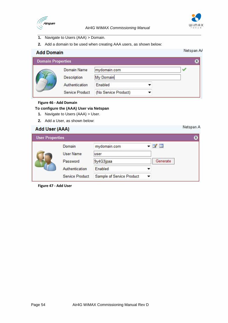
1. Navigate to Users (AAA) > Domain.
2. Add a domain to be used when creating AAA users, as shown below:
Figure 46 - Add Domain
To configure the (AAA) User via Netspan
1. Navigate to Users (AAA) > User.
2. Add a User, as shown below:
Figure 47 - Add User
Air4G WiMAX Commissioning Manual
Page 55 Air4G WiMAX Commissioning Manual Rev D
5.2.2 Untagged mode
BS Configuration:
Refer to sections 2-3 in order to discover the BS in Netspan.
Navigate to Configuration Management > select Node > Node.
Select the configured BS and click Edit at the bottom of the page to enter the Edit Mode.
Air Interface Type and Hardware are set automatically with 16e, Air4G WiMAX(Read only).
Select Mobility Mode = Fixed (No ASN-GW).
Check - Managed.
Set Ready For Service = Ready For Service.
Set System Profile with a latest default Netspan Profile for MMXe.
Set Management Profile – as described above.
Set VoIP Profile - according to section 6 if no VoiceMAX is used, set this profile to not set.
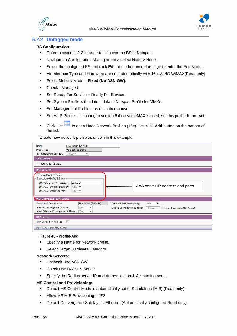
Click List to open Node Network Profiles (16e) List, click Add button on the bottom of the list.
Create new network profile as shown in this example:
Figure 48 - Profile-Add
Specify a Name for Network profile.
Select Target Hardware Category.
Network Servers:
Uncheck Use ASN-GW.
Check Use RADIUS Server.
Specify the Radius server IP and Authentication & Accounting ports.
MS Control and Provisioning:
Default MS Control Mode is automatically set to Standalone (MIB) (Read only).
Allow MS MIB Provisioning =YES
Default Convergence Sub layer =Ethernet (Automatically configured Read only).
AAA server IP address and ports
Air4G WiMAX Commissioning Manual
Page 56 Air4G WiMAX Commissioning Manual Rev D
Allow IP Convergence Sub layer=Yes (Automatically configured Read only).
Set Allow Ethernet Convergence Sub layer = Yes.
NTP Servers:
Uncheck NTP Server 1 IP Address.
Click Ok to save settings.
5.2.2.1 Creating Bridge Profile for Untagged Traffic:
The procedure is as follows:
Create Multicast Service class.
Create VLAN configuration VLAN 4087.
Create BS VLAN bridge profile.
5.2.2.2 Creating Multicast Service Class
Navigate to Service Profiles > Service class > Add
Create a new service class as follows:
Air4G WiMAX Commissioning Manual
Page 57 Air4G WiMAX Commissioning Manual Rev D
Figure 49 - Edit Service Class
Click OK to save settings.
5.2.2.3 Creating VLAN for Untagged Traffic
Navigate to Service Profiles > VLAN configuration > Add
Create a new VLAN as follows:
Name and BE scheduling type
Set the MIR- 50K
Select “Disabled”
Select “not requested”
Check these parameters
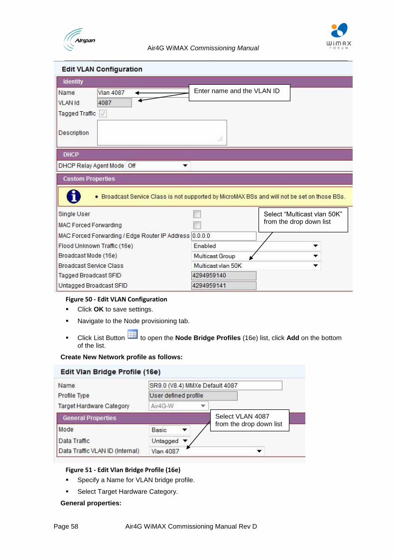
Air4G WiMAX Commissioning Manual
Page 58 Air4G WiMAX Commissioning Manual Rev D
Figure 50 - Edit VLAN Configuration
Click OK to save settings.
Navigate to the Node provisioning tab.
Click List Button to open the Node Bridge Profiles (16e) list, click Add on the bottom of the list.
Create New Network profile as follows:
Figure 51 - Edit Vlan Bridge Profile (16e)
Specify a Name for VLAN bridge profile.
Select Target Hardware Category.
General properties:
Select VLAN 4087 from the drop down list
Select “Multicast vlan 50K” from the drop down list
Enter name and the VLAN ID
Air4G WiMAX Commissioning Manual
Page 59 Air4G WiMAX Commissioning Manual Rev D
Mode = basic
Data traffic = Untagged
Select VLAN 4087 – Create new VLAN
Click Ok to save settings.
Return to Edit Node Provisioning.
Set traffic port = Traffic and management Ethernet.
Set IP address and Subnet mask according to BS configuration as configured on the BS management web page.
In the Standalone RADIUS Client = Set IP address and Subnet mask according to BS configuration as configured on the BS management web page and the RADIUS Shared Secret.
5.2.2.4 Set Channel Properties
1. Check Enable channel and set RF Properties and characteristics according BS HW and RF requirement – see RF Profile.
2. Set the Suitable MCS profile – see MCS Profile.
3. Set the Suitable PHY profile – see PHY Profile.
4. Set MAC Profile Named – Air4G Authentication Only, HARQ from the drop down menu.
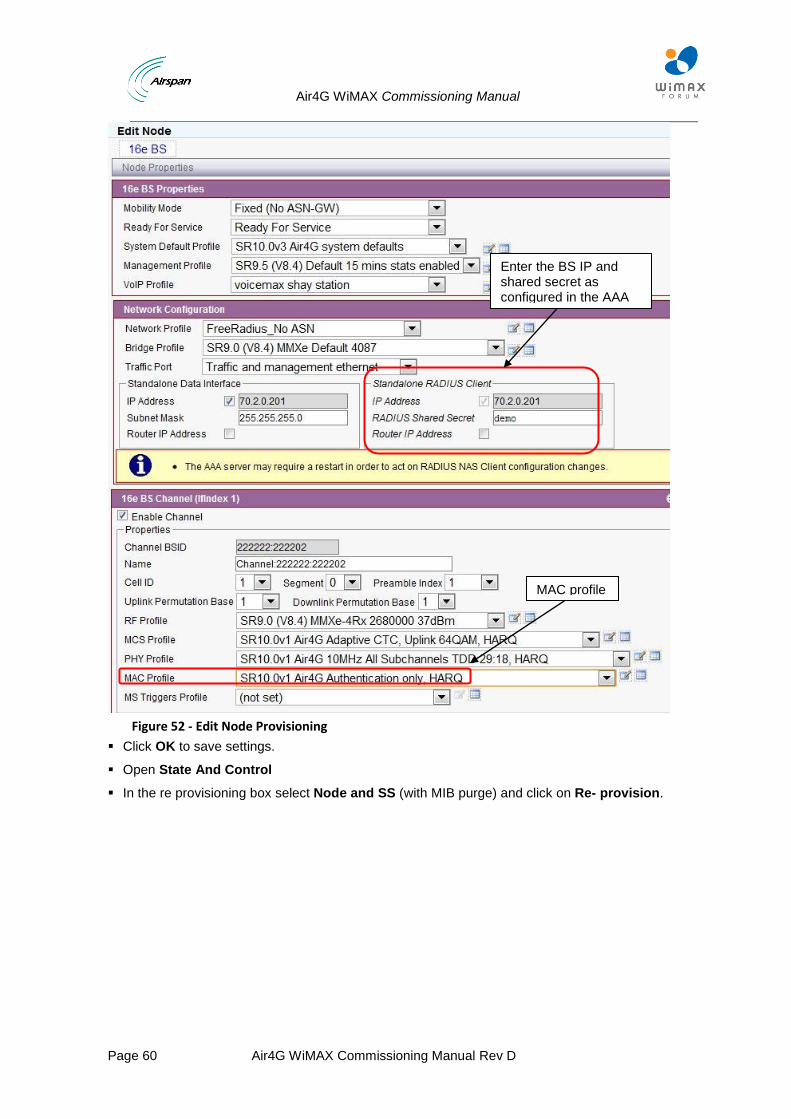
Air4G WiMAX Commissioning Manual
Page 60 Air4G WiMAX Commissioning Manual Rev D
Figure 52 - Edit Node Provisioning
Click OK to save settings.
Open State And Control
In the re provisioning box select Node and SS (with MIB purge) and click on Re- provision.
Enter the BS IP and shared secret as configured in the AAA
MAC profile
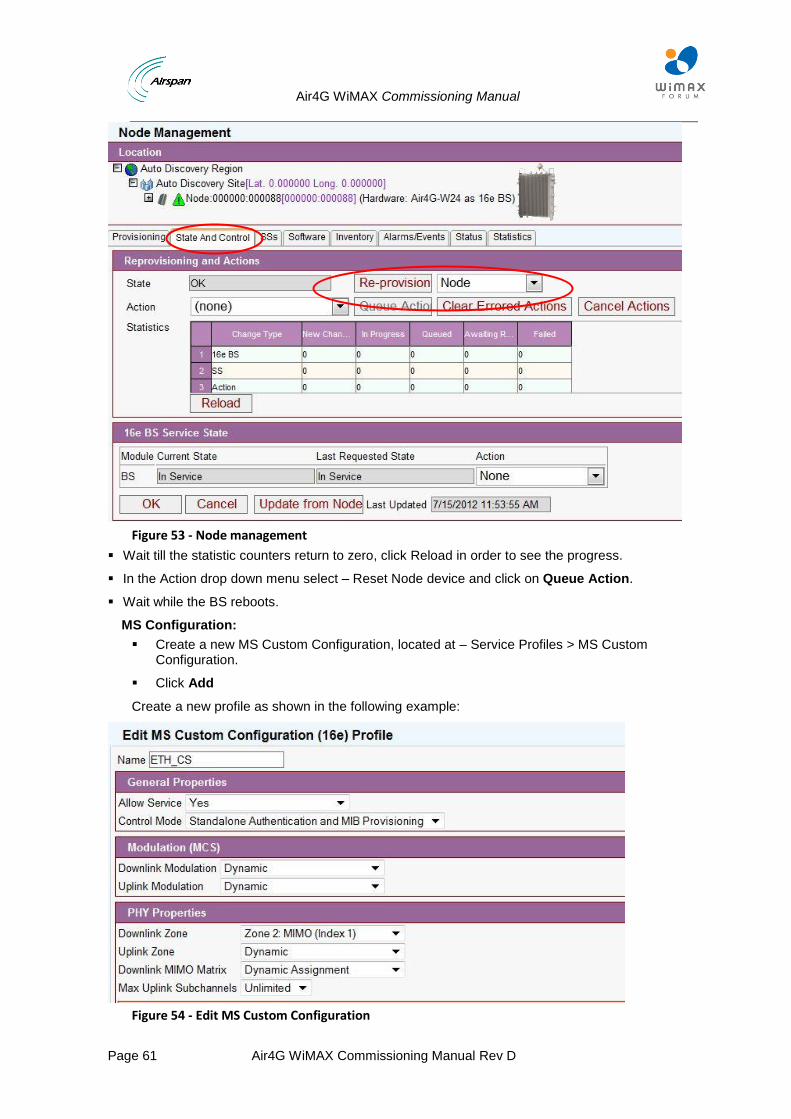
Air4G WiMAX Commissioning Manual
Page 61 Air4G WiMAX Commissioning Manual Rev D
Figure 53 - Node management
Wait till the statistic counters return to zero, click Reload in order to see the progress.
In the Action drop down menu select – Reset Node device and click on Queue Action.
Wait while the BS reboots.
MS Configuration:
Create a new MS Custom Configuration, located at – Service Profiles > MS Custom Configuration.
Click Add
Create a new profile as shown in the following example:
Figure 54 - Edit MS Custom Configuration
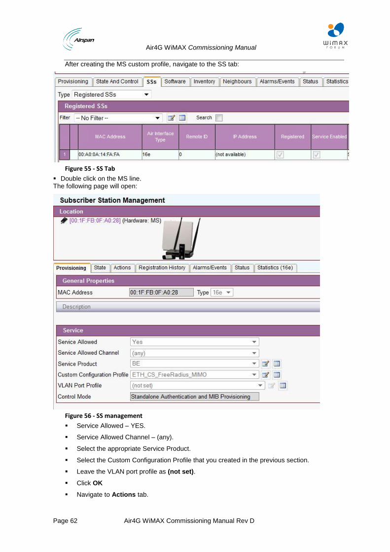
Air4G WiMAX Commissioning Manual
Page 62 Air4G WiMAX Commissioning Manual Rev D
After creating the MS custom profile, navigate to the SS tab:
Figure 55 - SS Tab
Double click on the MS line. The following page will open:
Figure 56 - SS management
Service Allowed – YES.
Service Allowed Channel – (any).
Select the appropriate Service Product.
Select the Custom Configuration Profile that you created in the previous section.
Leave the VLAN port profile as (not set).
Click OK
Navigate to Actions tab.
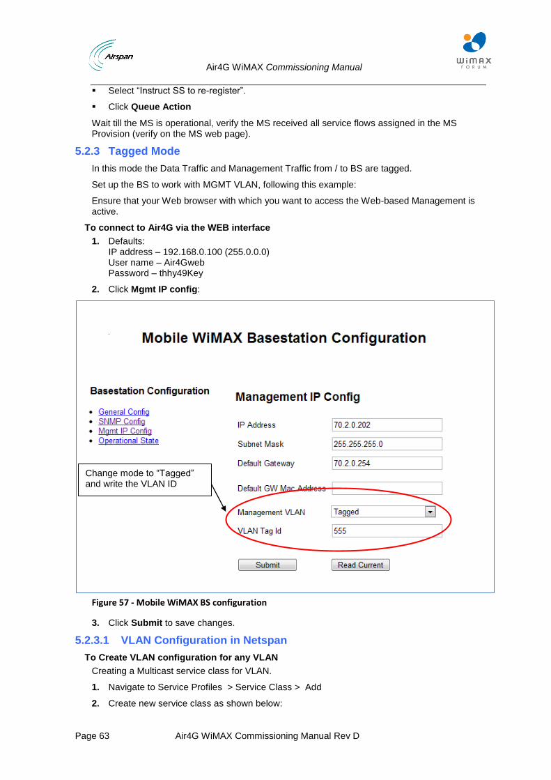
Air4G WiMAX Commissioning Manual
Page 63 Air4G WiMAX Commissioning Manual Rev D
Select “Instruct SS to re-register”.
Click Queue Action
Wait till the MS is operational, verify the MS received all service flows assigned in the MS Provision (verify on the MS web page).
5.2.3 Tagged Mode
In this mode the Data Traffic and Management Traffic from / to BS are tagged.
Set up the BS to work with MGMT VLAN, following this example:
Ensure that your Web browser with which you want to access the Web-based Management is active.
To connect to Air4G via the WEB interface
1. Defaults: IP address – 192.168.0.100 (255.0.0.0) User name – Air4Gweb Password – thhy49Key
2. Click Mgmt IP config:
Figure 57 - Mobile WiMAX BS configuration
3. Click Submit to save changes.
5.2.3.1 VLAN Configuration in Netspan
To Create VLAN configuration for any VLAN
Creating a Multicast service class for VLAN.
1. Navigate to Service Profiles > Service Class > Add
2. Create new service class as shown below:
Change mode to “Tagged” and write the VLAN ID
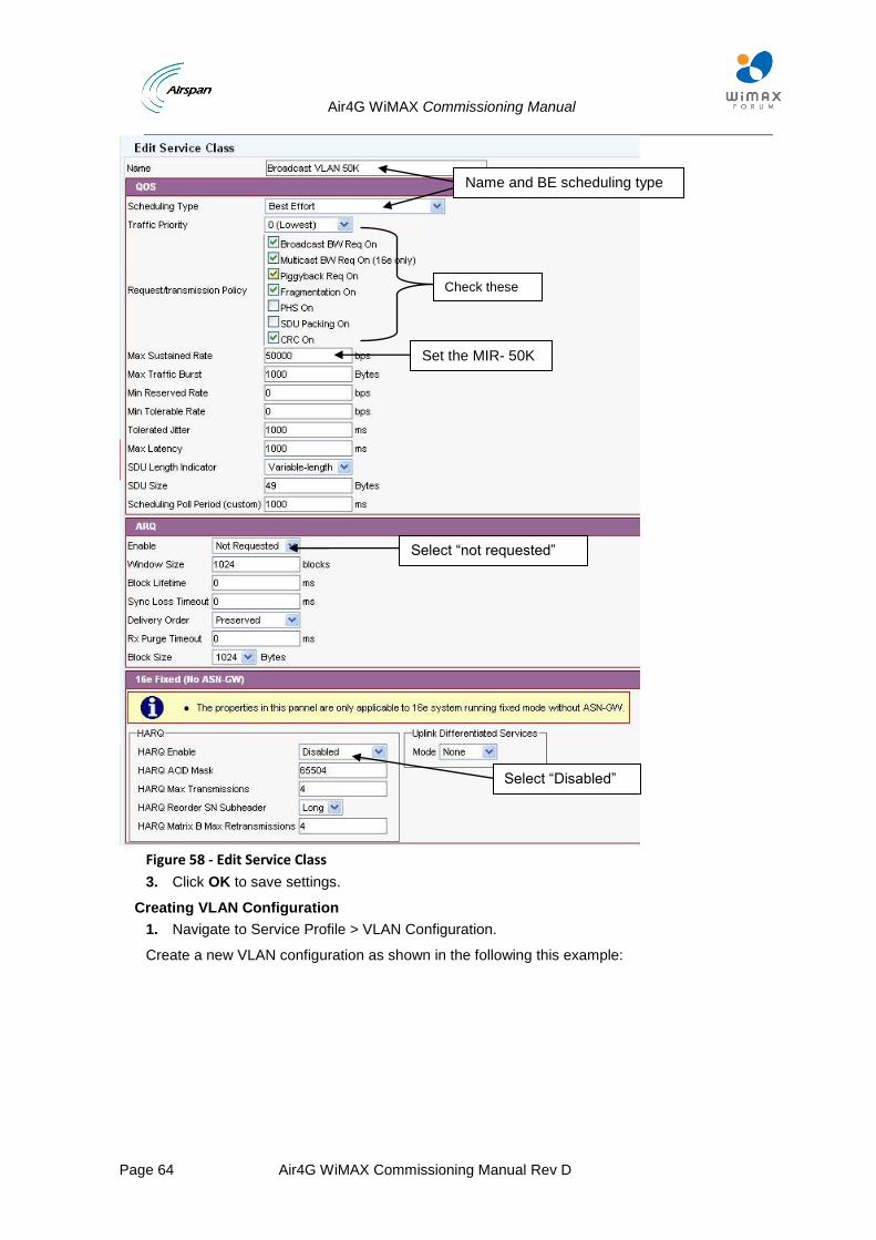
Air4G WiMAX Commissioning Manual
Page 64 Air4G WiMAX Commissioning Manual Rev D
Figure 58 - Edit Service Class
3. Click OK to save settings.
Creating VLAN Configuration
1. Navigate to Service Profile > VLAN Configuration.
Create a new VLAN configuration as shown in the following this example:
Name and BE scheduling type
Set the MIR- 50K
Select “Disabled”
Select “not requested”
Check these parameters
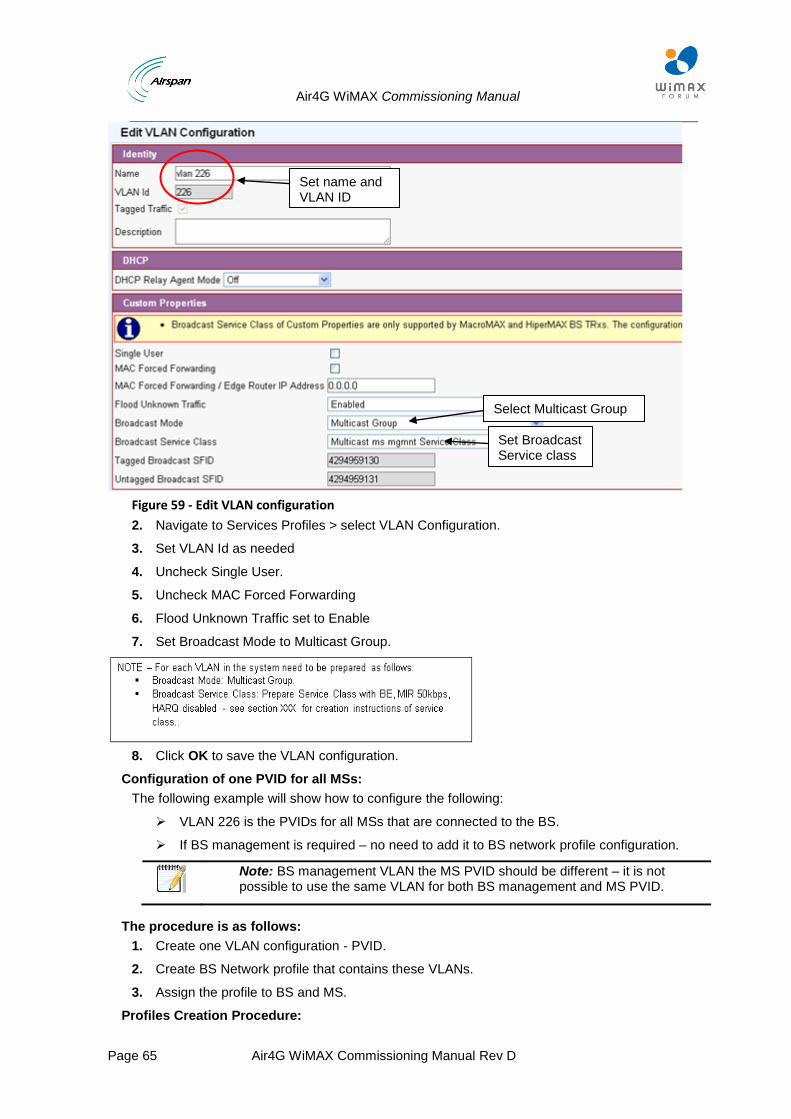
Air4G WiMAX Commissioning Manual
Page 65 Air4G WiMAX Commissioning Manual Rev D
Figure 59 - Edit VLAN configuration
2. Navigate to Services Profiles > select VLAN Configuration.
3. Set VLAN Id as needed
4. Uncheck Single User.
5. Uncheck MAC Forced Forwarding
6. Flood Unknown Traffic set to Enable
7. Set Broadcast Mode to Multicast Group.
8. Click OK to save the VLAN configuration.
Configuration of one PVID for all MSs:
The following example will show how to configure the following:
VLAN 226 is the PVIDs for all MSs that are connected to the BS.
If BS management is required – no need to add it to BS network profile configuration.
Note: BS management VLAN the MS PVID should be different – it is not possible to use the same VLAN for both BS management and MS PVID.
The procedure is as follows:
1. Create one VLAN configuration - PVID.
2. Create BS Network profile that contains these VLANs.
3. Assign the profile to BS and MS.
Profiles Creation Procedure:
Set name and VLAN ID
Select Multicast Group
Set Broadcast Service class
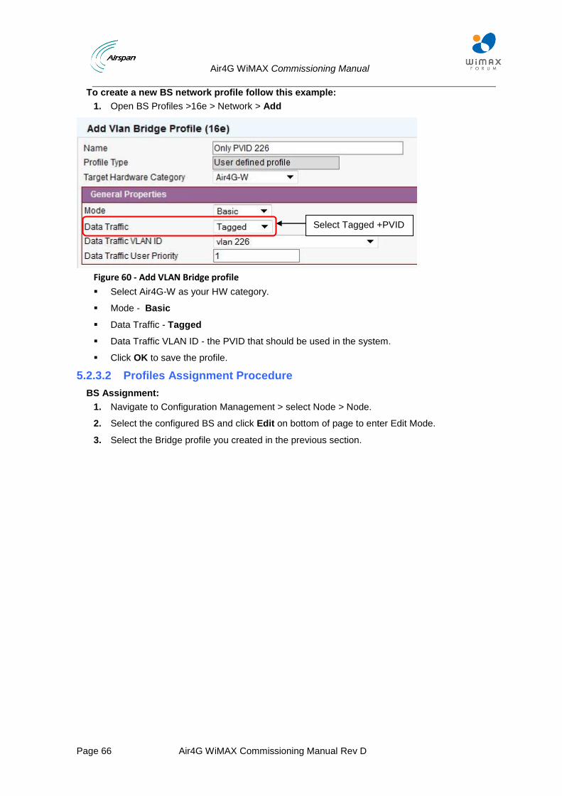
Air4G WiMAX Commissioning Manual
Page 66 Air4G WiMAX Commissioning Manual Rev D
To create a new BS network profile follow this example:
1. Open BS Profiles >16e > Network > Add
Figure 60 - Add VLAN Bridge profile
Select Air4G-W as your HW category.
Mode - Basic
Data Traffic - Tagged
Data Traffic VLAN ID - the PVID that should be used in the system.
Click OK to save the profile.
5.2.3.2 Profiles Assignment Procedure
BS Assignment:
1. Navigate to Configuration Management > select Node > Node.
2. Select the configured BS and click Edit on bottom of page to enter Edit Mode.
3. Select the Bridge profile you created in the previous section.
Select Tagged +PVID
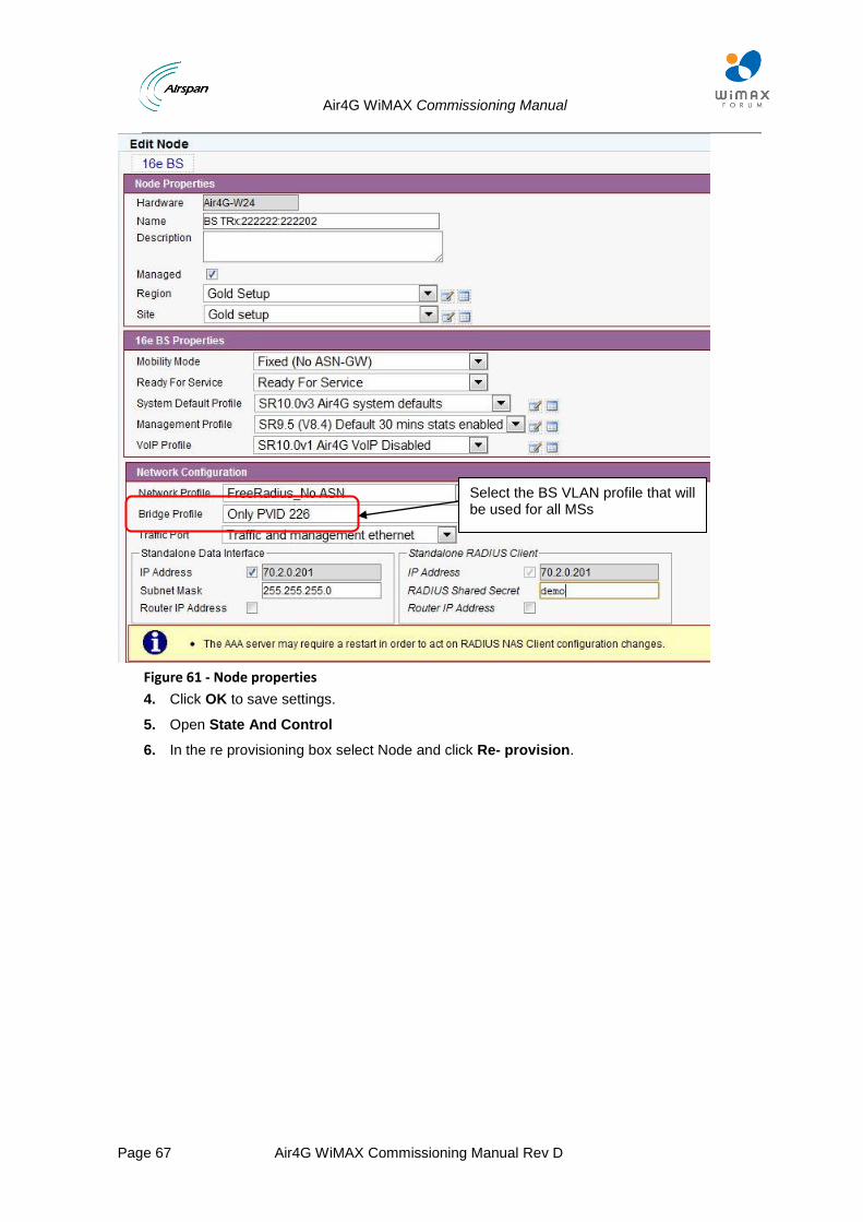
Air4G WiMAX Commissioning Manual
Page 67 Air4G WiMAX Commissioning Manual Rev D
Figure 61 - Node properties
4. Click OK to save settings.
5. Open State And Control
6. In the re provisioning box select Node and click Re- provision.
Select the BS VLAN profile that will be used for all MSs
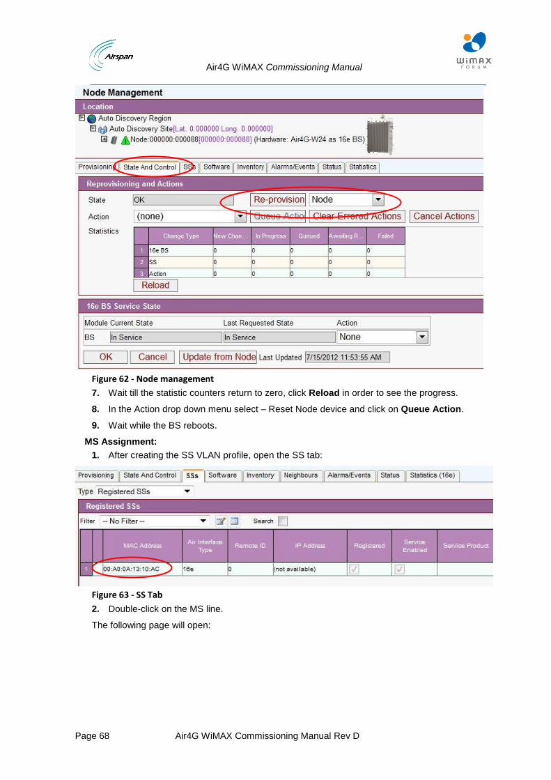
Air4G WiMAX Commissioning Manual
Page 68 Air4G WiMAX Commissioning Manual Rev D
Figure 62 - Node management
7. Wait till the statistic counters return to zero, click Reload in order to see the progress.
8. In the Action drop down menu select – Reset Node device and click on Queue Action.
9. Wait while the BS reboots.
MS Assignment:
1. After creating the SS VLAN profile, open the SS tab:
Figure 63 - SS Tab
2. Double-click on the MS line.
The following page will open:
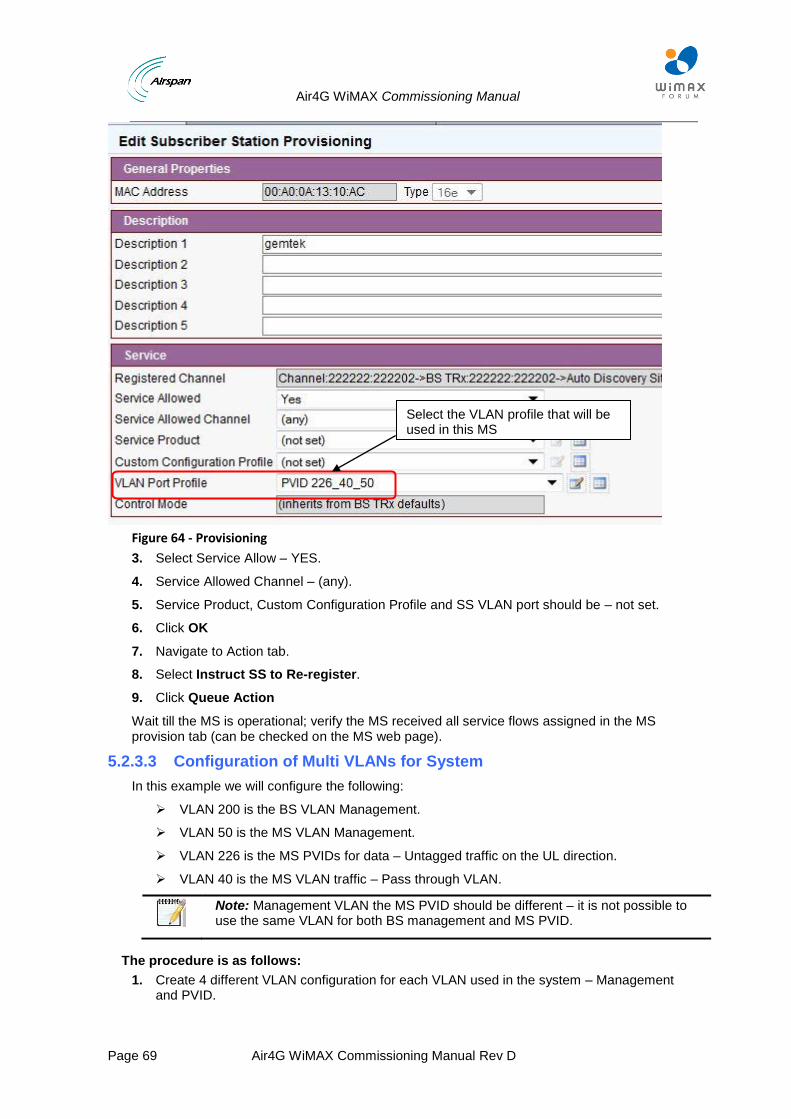
Air4G WiMAX Commissioning Manual
Page 69 Air4G WiMAX Commissioning Manual Rev D
Figure 64 - Provisioning
3. Select Service Allow – YES.
4. Service Allowed Channel – (any).
5. Service Product, Custom Configuration Profile and SS VLAN port should be – not set.
6. Click OK
7. Navigate to Action tab.
8. Select Instruct SS to Re-register.
9. Click Queue Action
Wait till the MS is operational; verify the MS received all service flows assigned in the MS provision tab (can be checked on the MS web page).
5.2.3.3 Configuration of Multi VLANs for System
In this example we will configure the following:
VLAN 200 is the BS VLAN Management.
VLAN 50 is the MS VLAN Management.
VLAN 226 is the MS PVIDs for data – Untagged traffic on the UL direction.
VLAN 40 is the MS VLAN traffic – Pass through VLAN.
Note: Management VLAN the MS PVID should be different – it is not possible to use the same VLAN for both BS management and MS PVID.
The procedure is as follows:
1. Create 4 different VLAN configuration for each VLAN used in the system – Management and PVID.
Select the VLAN profile that will be used in this MS
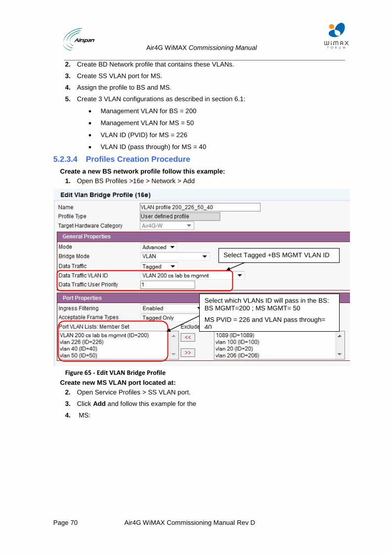
Air4G WiMAX Commissioning Manual
Page 70 Air4G WiMAX Commissioning Manual Rev D
2. Create BD Network profile that contains these VLANs.
3. Create SS VLAN port for MS.
4. Assign the profile to BS and MS.
5. Create 3 VLAN configurations as described in section 6.1:
Management VLAN for BS = 200
Management VLAN for MS = 50
VLAN ID (PVID) for MS = 226
VLAN ID (pass through) for MS = 40
5.2.3.4 Profiles Creation Procedure
Create a new BS network profile follow this example:
1. Open BS Profiles >16e > Network > Add
Figure 65 - Edit VLAN Bridge Profile
Create new MS VLAN port located at:
2. Open Service Profiles > SS VLAN port.
3. Click Add and follow this example for the
4. MS:
Select Tagged +BS MGMT VLAN ID
Select which VLANs ID will pass in the BS: BS MGMT=200 ; MS MGMT= 50
MS PVID = 226 and VLAN pass through= 40
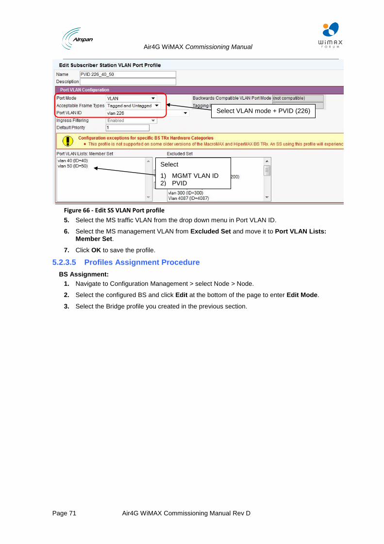
Air4G WiMAX Commissioning Manual
Page 71 Air4G WiMAX Commissioning Manual Rev D
Figure 66 - Edit SS VLAN Port profile
5. Select the MS traffic VLAN from the drop down menu in Port VLAN ID.
6. Select the MS management VLAN from Excluded Set and move it to Port VLAN Lists: Member Set.
7. Click OK to save the profile.
5.2.3.5 Profiles Assignment Procedure
BS Assignment:
1. Navigate to Configuration Management > select Node > Node.
2. Select the configured BS and click Edit at the bottom of the page to enter Edit Mode.
3. Select the Bridge profile you created in the previous section.
Select VLAN mode + PVID (226)
Select
1) MGMT VLAN ID 2) PVID

Air4G WiMAX Commissioning Manual
Page 72 Air4G WiMAX Commissioning Manual Rev D
Figure 67 - Edit Node Provisioning
4. Click OK to save settings.
5. Open State and Control.
6. In the re provisioning box select Node and click Re- provision.
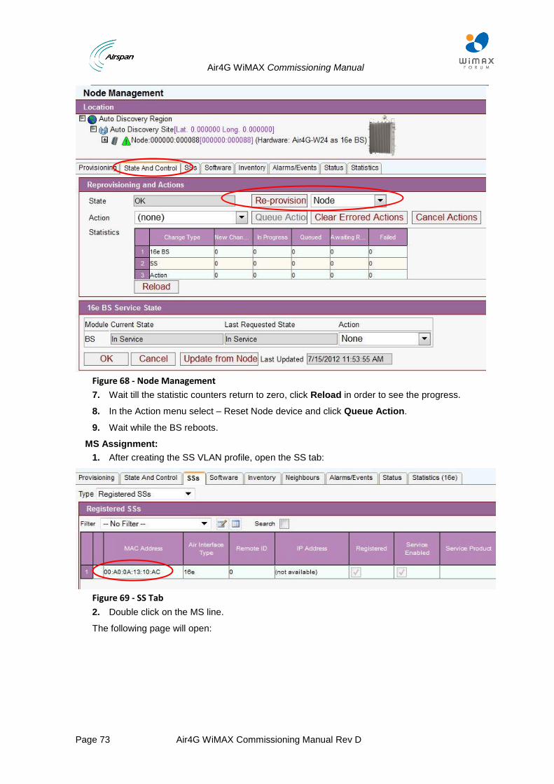
Air4G WiMAX Commissioning Manual
Page 73 Air4G WiMAX Commissioning Manual Rev D
Figure 68 - Node Management
7. Wait till the statistic counters return to zero, click Reload in order to see the progress.
8. In the Action menu select – Reset Node device and click Queue Action.
9. Wait while the BS reboots.
MS Assignment:
1. After creating the SS VLAN profile, open the SS tab:
Figure 69 - SS Tab
2. Double click on the MS line.
The following page will open:
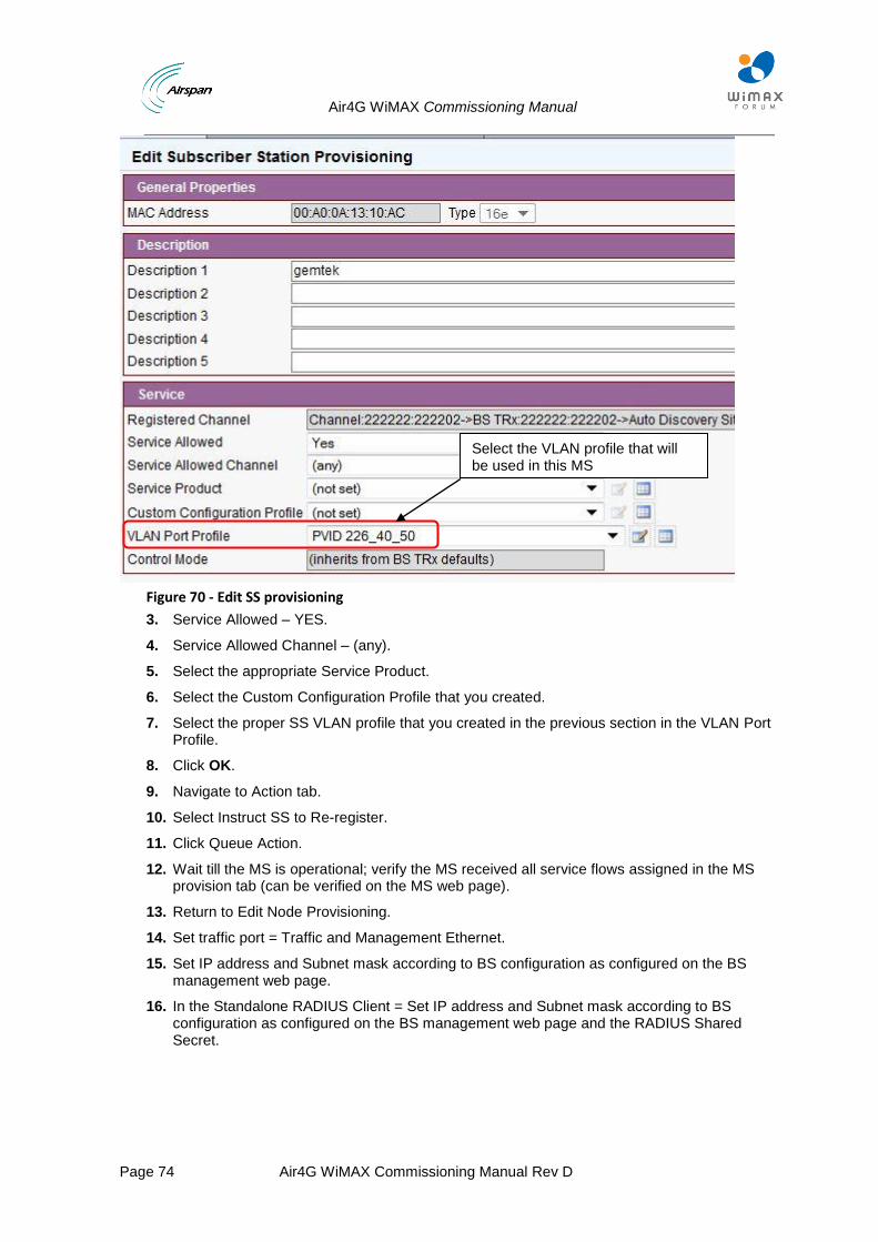
Air4G WiMAX Commissioning Manual
Page 74 Air4G WiMAX Commissioning Manual Rev D
Figure 70 - Edit SS provisioning
3. Service Allowed – YES.
4. Service Allowed Channel – (any).
5. Select the appropriate Service Product.
6. Select the Custom Configuration Profile that you created.
7. Select the proper SS VLAN profile that you created in the previous section in the VLAN Port Profile.
8. Click OK.
9. Navigate to Action tab.
10. Select Instruct SS to Re-register.
11. Click Queue Action.
12. Wait till the MS is operational; verify the MS received all service flows assigned in the MS provision tab (can be verified on the MS web page).
13. Return to Edit Node Provisioning.
14. Set traffic port = Traffic and Management Ethernet.
15. Set IP address and Subnet mask according to BS configuration as configured on the BS management web page.
16. In the Standalone RADIUS Client = Set IP address and Subnet mask according to BS configuration as configured on the BS management web page and the RADIUS Shared Secret.
Select the VLAN profile that will be used in this MS
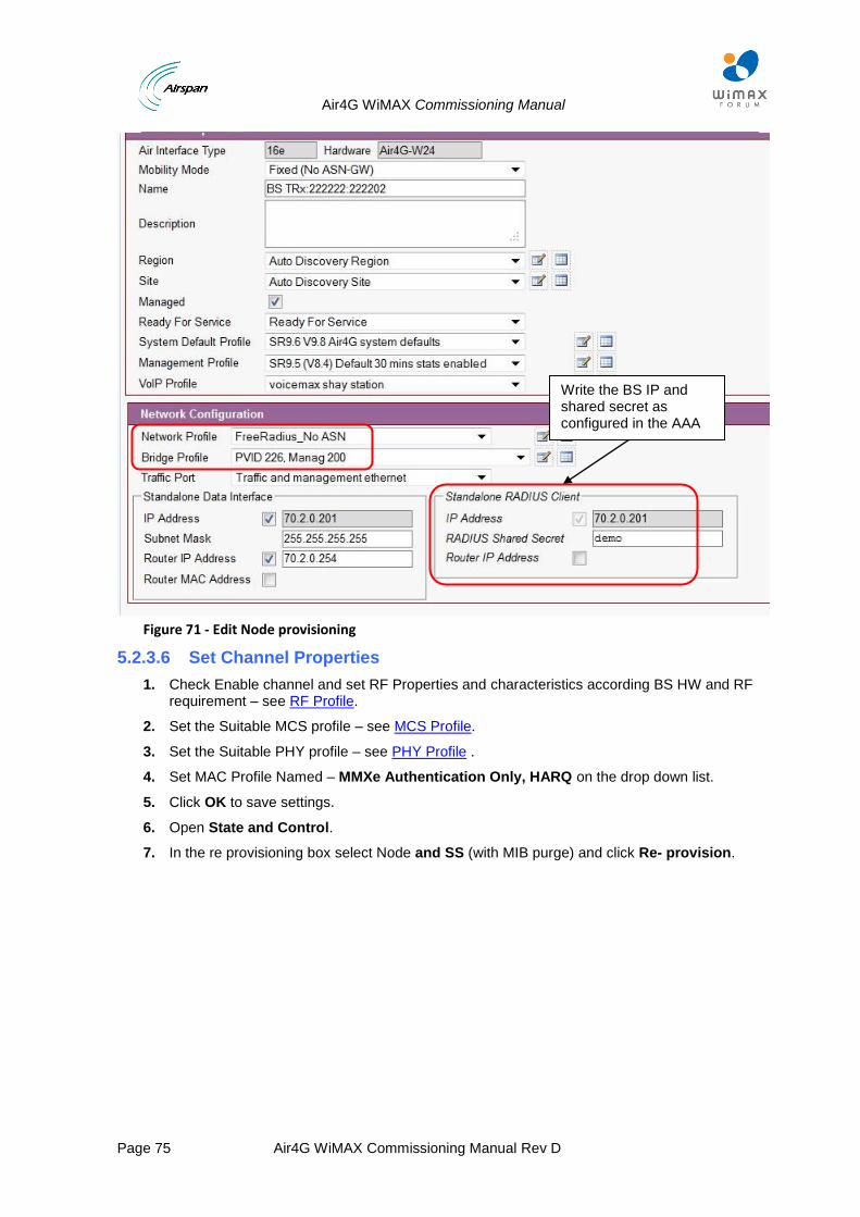
Air4G WiMAX Commissioning Manual
Page 75 Air4G WiMAX Commissioning Manual Rev D
Figure 71 - Edit Node provisioning
5.2.3.6 Set Channel Properties
1. Check Enable channel and set RF Properties and characteristics according BS HW and RF requirement – see RF Profile.
2. Set the Suitable MCS profile – see MCS Profile.
3. Set the Suitable PHY profile – see PHY Profile .
4. Set MAC Profile Named – MMXe Authentication Only, HARQ on the drop down list.
5. Click OK to save settings.
6. Open State and Control.
7. In the re provisioning box select Node and SS (with MIB purge) and click Re- provision.
Write the BS IP and shared secret as configured in the AAA
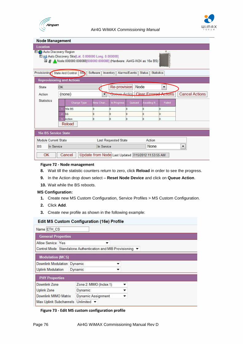
Air4G WiMAX Commissioning Manual
Page 76 Air4G WiMAX Commissioning Manual Rev D
Figure 72 - Node management
8. Wait till the statistic counters return to zero, click Reload in order to see the progress.
9. In the Action drop down select – Reset Node Device and click on Queue Action.
10. Wait while the BS reboots.
MS Configuration:
1. Create new MS Custom Configuration, Service Profiles > MS Custom Configuration.
2. Click Add.
3. Create new profile as shown in the following example:
Figure 73 - Edit MS custom configuration profile
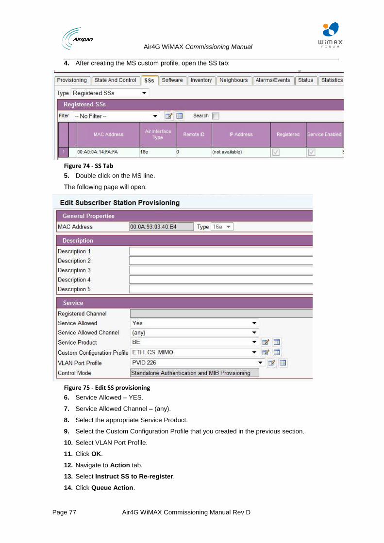
Air4G WiMAX Commissioning Manual
Page 77 Air4G WiMAX Commissioning Manual Rev D
4. After creating the MS custom profile, open the SS tab:
Figure 74 - SS Tab
5. Double click on the MS line.
The following page will open:
Figure 75 - Edit SS provisioning
6. Service Allowed – YES.
7. Service Allowed Channel – (any).
8. Select the appropriate Service Product.
9. Select the Custom Configuration Profile that you created in the previous section.
10. Select VLAN Port Profile.
11. Click OK.
12. Navigate to Action tab.
13. Select Instruct SS to Re-register.
14. Click Queue Action.
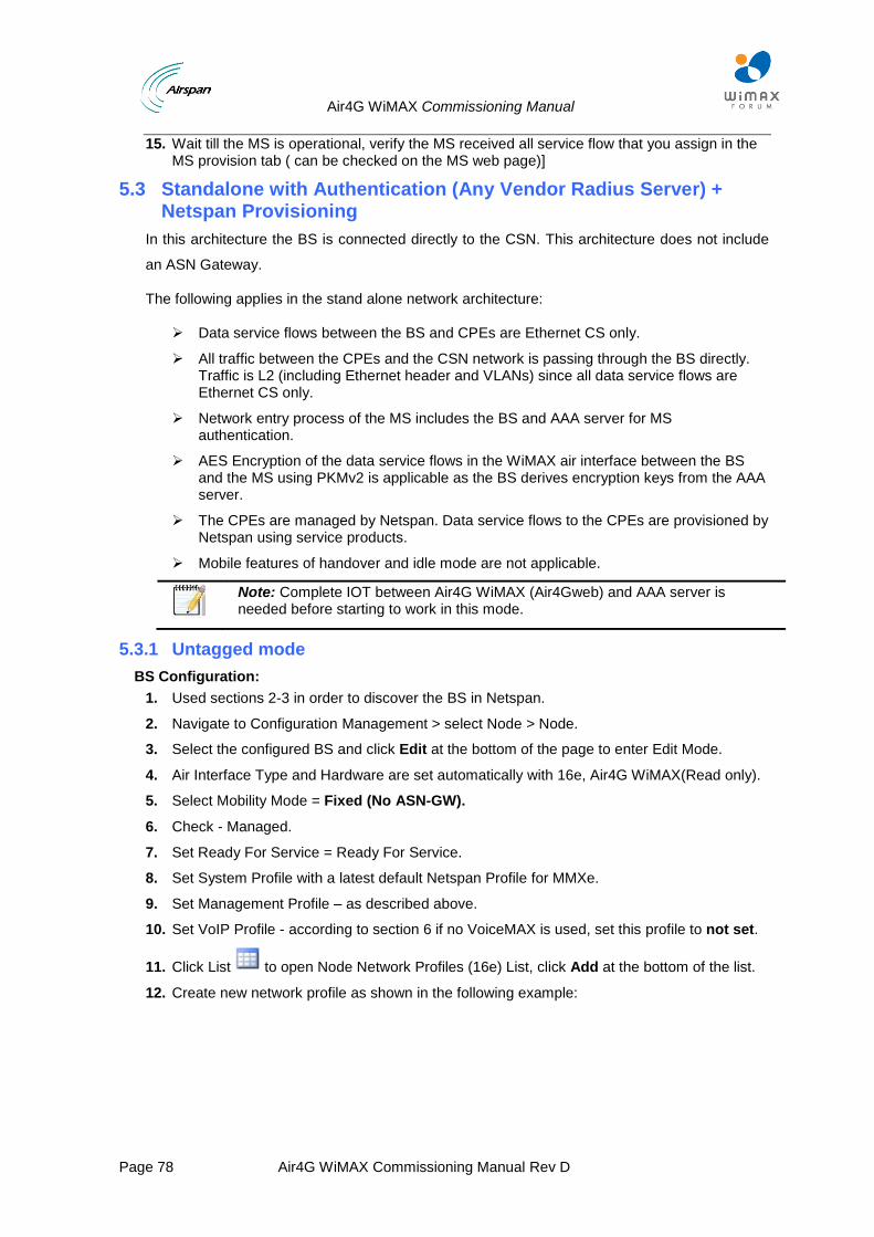
Air4G WiMAX Commissioning Manual
Page 78 Air4G WiMAX Commissioning Manual Rev D
15. Wait till the MS is operational, verify the MS received all service flow that you assign in the MS provision tab ( can be checked on the MS web page)]
5.3 Standalone with Authentication (Any Vendor Radius Server) + Netspan Provisioning
In this architecture the BS is connected directly to the CSN. This architecture does not include
an ASN Gateway.
The following applies in the stand alone network architecture:
Data service flows between the BS and CPEs are Ethernet CS only.
All traffic between the CPEs and the CSN network is passing through the BS directly. Traffic is L2 (including Ethernet header and VLANs) since all data service flows are Ethernet CS only.
Network entry process of the MS includes the BS and AAA server for MS authentication.
AES Encryption of the data service flows in the WiMAX air interface between the BS and the MS using PKMv2 is applicable as the BS derives encryption keys from the AAA server.
The CPEs are managed by Netspan. Data service flows to the CPEs are provisioned by Netspan using service products.
Mobile features of handover and idle mode are not applicable.
Note: Complete IOT between Air4G WiMAX (Air4Gweb) and AAA server is needed before starting to work in this mode.
5.3.1 Untagged mode
BS Configuration:
1. Used sections 2-3 in order to discover the BS in Netspan.
2. Navigate to Configuration Management > select Node > Node.
3. Select the configured BS and click Edit at the bottom of the page to enter Edit Mode.
4. Air Interface Type and Hardware are set automatically with 16e, Air4G WiMAX(Read only).
5. Select Mobility Mode = Fixed (No ASN-GW).
6. Check - Managed.
7. Set Ready For Service = Ready For Service.
8. Set System Profile with a latest default Netspan Profile for MMXe.
9. Set Management Profile – as described above.
10. Set VoIP Profile - according to section 6 if no VoiceMAX is used, set this profile to not set.
11. Click List to open Node Network Profiles (16e) List, click Add at the bottom of the list.
12. Create new network profile as shown in the following example:
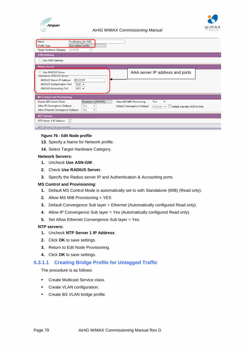
Air4G WiMAX Commissioning Manual
Page 79 Air4G WiMAX Commissioning Manual Rev D
Figure 76 - Edit Node profile
13. Specify a Name for Network profile.
14. Select Target Hardware Category.
Network Servers:
1. Uncheck Use ASN-GW.
2. Check Use RADIUS Server.
3. Specify the Radius server IP and Authentication & Accounting ports.
MS Control and Provisioning:
1. Default MS Control Mode is automatically set to with Standalone (MIB) (Read only).
2. Allow MS MIB Provisioning = YES
3. Default Convergence Sub layer = Ethernet (Automatically configured Read only).
4. Allow IP Convergence Sub layer = Yes (Automatically configured Read only).
5. Set Allow Ethernet Convergence Sub layer = Yes.
NTP servers:
1. Uncheck NTP Server 1 IP Address.
2. Click OK to save settings.
3. Return to Edit Node Provisioning.
4. Click OK to save settings.
5.3.1.1 Creating Bridge Profile for Untagged Traffic
The procedure is as follows:
Create Multicast Service class.
Create VLAN configuration.
Create BS VLAN bridge profile.
AAA server IP address and ports
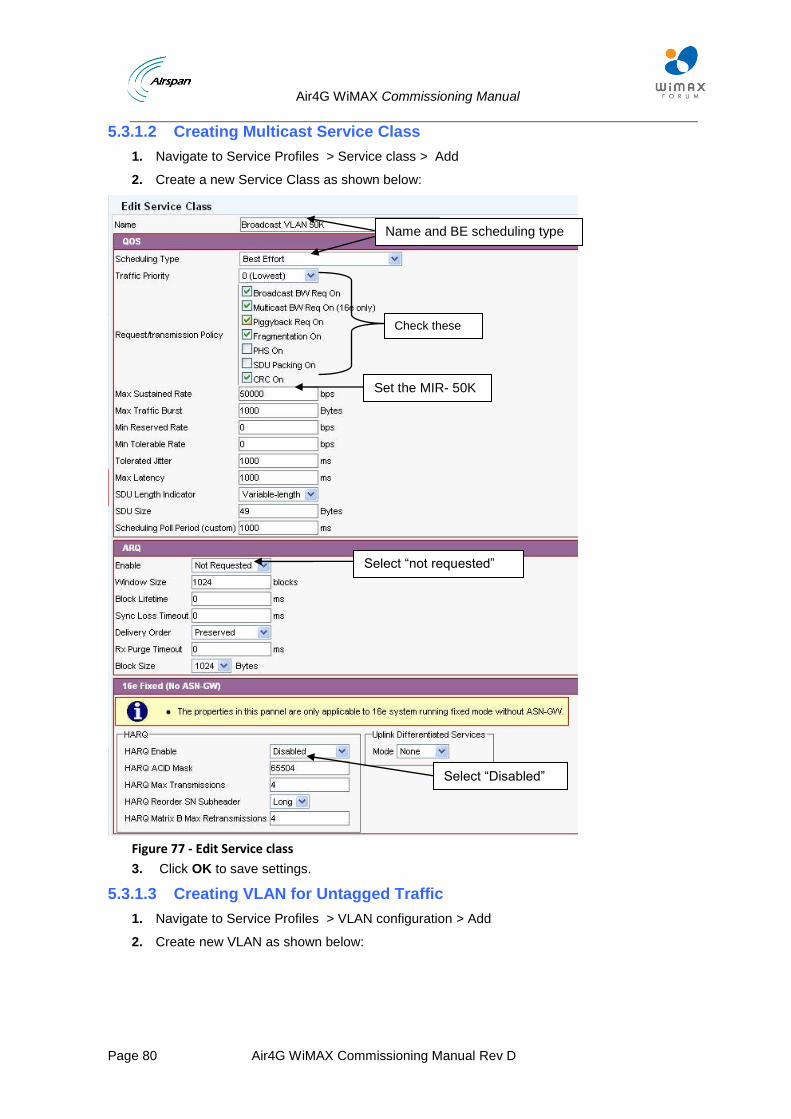
Air4G WiMAX Commissioning Manual
Page 80 Air4G WiMAX Commissioning Manual Rev D
5.3.1.2 Creating Multicast Service Class
1. Navigate to Service Profiles > Service class > Add
2. Create a new Service Class as shown below:
Figure 77 - Edit Service class
3. Click OK to save settings.
5.3.1.3 Creating VLAN for Untagged Traffic
1. Navigate to Service Profiles > VLAN configuration > Add
2. Create new VLAN as shown below:
Name and BE scheduling type
Set the MIR- 50K
Select “Disabled”
Select “not requested”
Check these parameters
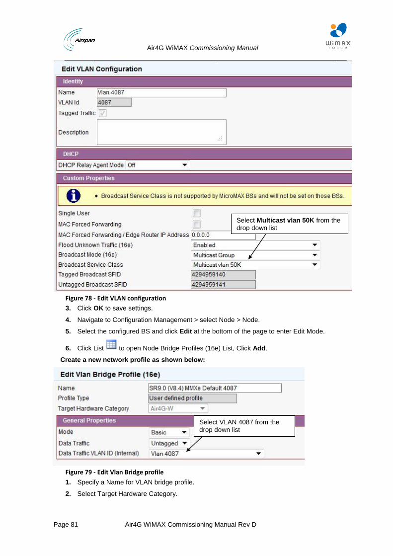
Air4G WiMAX Commissioning Manual
Page 81 Air4G WiMAX Commissioning Manual Rev D
Figure 78 - Edit VLAN configuration
3. Click OK to save settings.
4. Navigate to Configuration Management > select Node > Node.
5. Select the configured BS and click Edit at the bottom of the page to enter Edit Mode.
6. Click List to open Node Bridge Profiles (16e) List, Click Add.
Create a new network profile as shown below:
Figure 79 - Edit Vlan Bridge profile
1. Specify a Name for VLAN bridge profile.
2. Select Target Hardware Category.
Select Multicast vlan 50K from the drop down list
Select VLAN 4087 from the drop down list
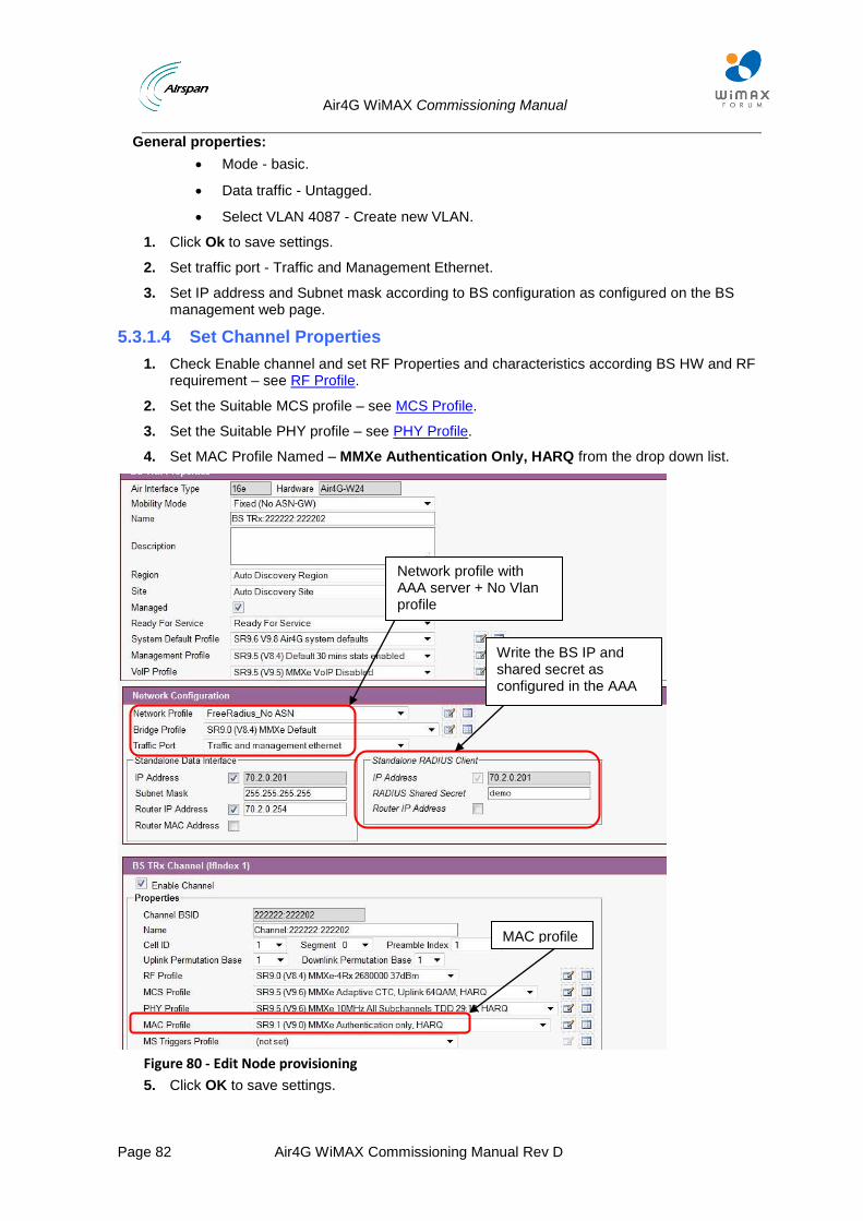
Air4G WiMAX Commissioning Manual
Page 82 Air4G WiMAX Commissioning Manual Rev D
General properties:
Mode - basic.
Data traffic - Untagged.
Select VLAN 4087 - Create new VLAN.
1. Click Ok to save settings.
2. Set traffic port - Traffic and Management Ethernet.
3. Set IP address and Subnet mask according to BS configuration as configured on the BS management web page.
5.3.1.4 Set Channel Properties
1. Check Enable channel and set RF Properties and characteristics according BS HW and RF requirement – see RF Profile.
2. Set the Suitable MCS profile – see MCS Profile.
3. Set the Suitable PHY profile – see PHY Profile.
4. Set MAC Profile Named – MMXe Authentication Only, HARQ from the drop down list.
Figure 80 - Edit Node provisioning
5. Click OK to save settings.
Write the BS IP and shared secret as configured in the AAA
MAC profile
Network profile with AAA server + No Vlan profile
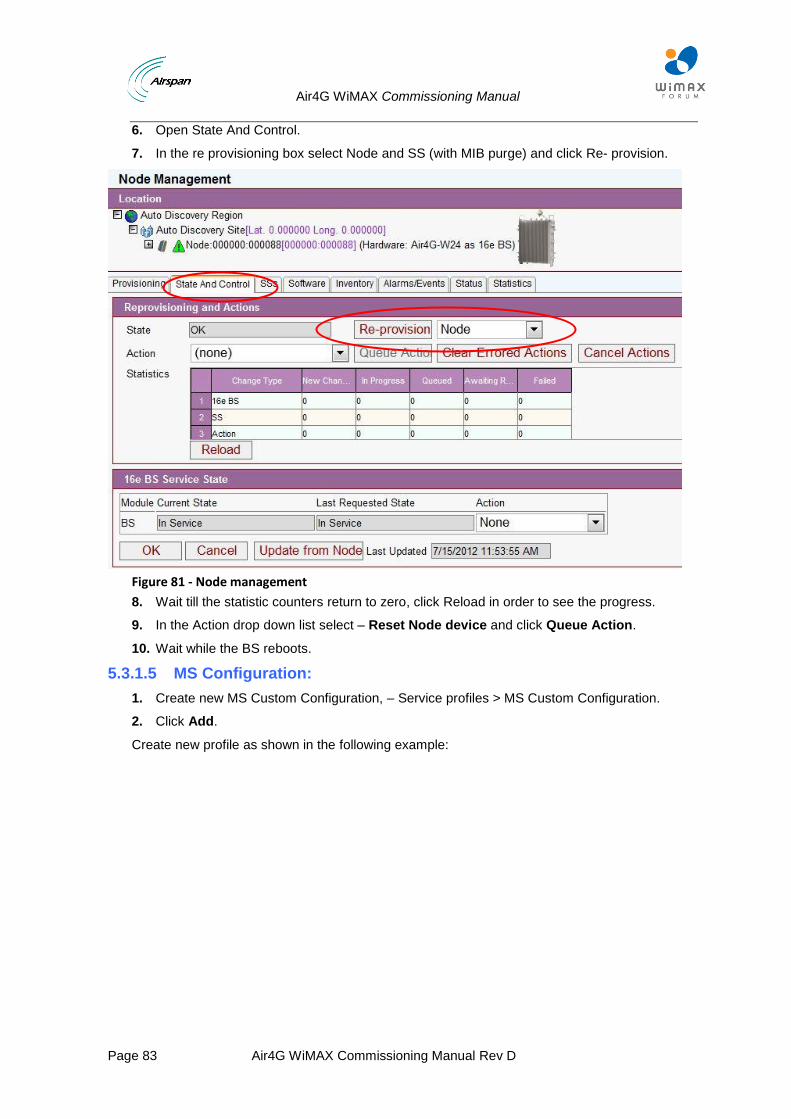
Air4G WiMAX Commissioning Manual
Page 83 Air4G WiMAX Commissioning Manual Rev D
6. Open State And Control.
7. In the re provisioning box select Node and SS (with MIB purge) and click Re- provision.
Figure 81 - Node management
8. Wait till the statistic counters return to zero, click Reload in order to see the progress.
9. In the Action drop down list select – Reset Node device and click Queue Action.
10. Wait while the BS reboots.
5.3.1.5 MS Configuration:
1. Create new MS Custom Configuration, – Service profiles > MS Custom Configuration.
2. Click Add.
Create new profile as shown in the following example:
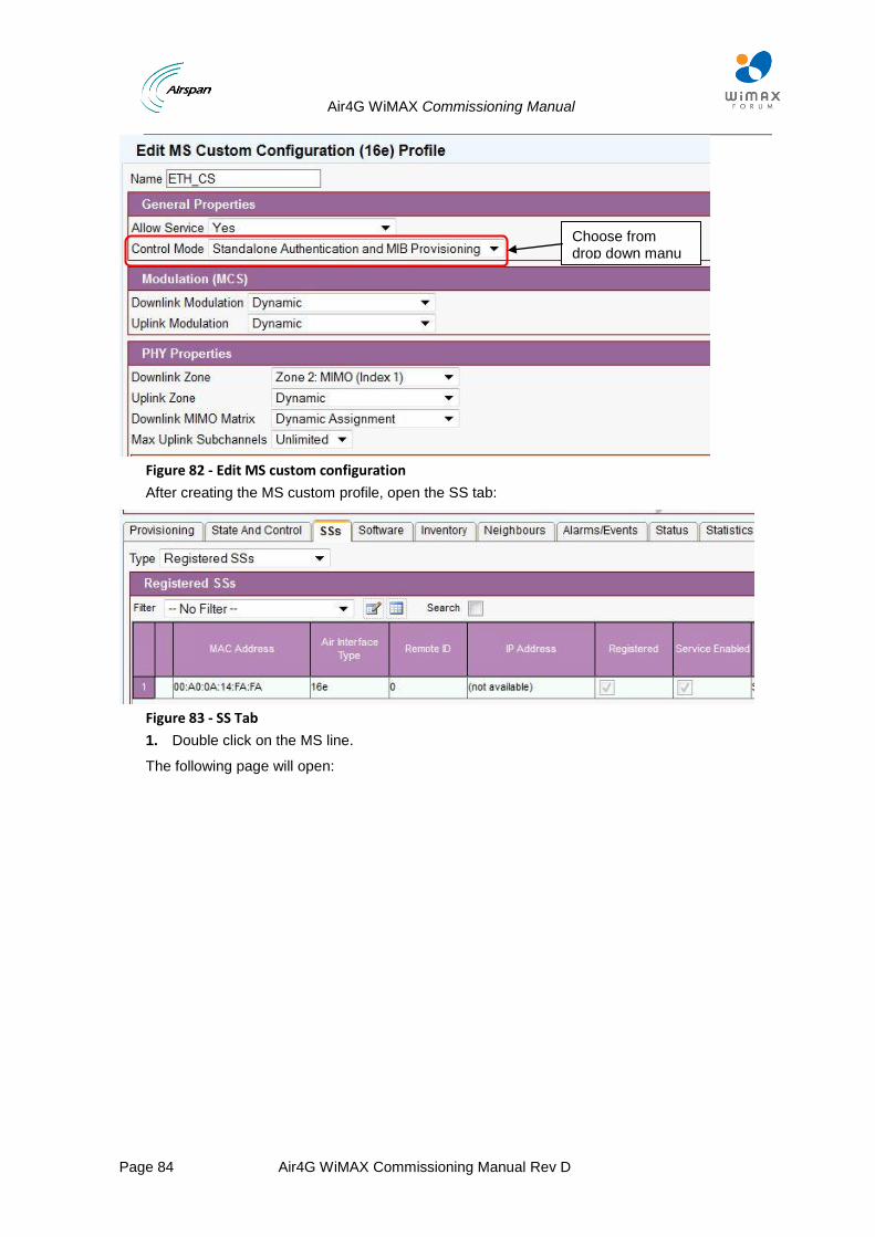
Air4G WiMAX Commissioning Manual
Page 84 Air4G WiMAX Commissioning Manual Rev D
Figure 82 - Edit MS custom configuration
After creating the MS custom profile, open the SS tab:
Figure 83 - SS Tab
1. Double click on the MS line.
The following page will open:
Choose from drop down manu
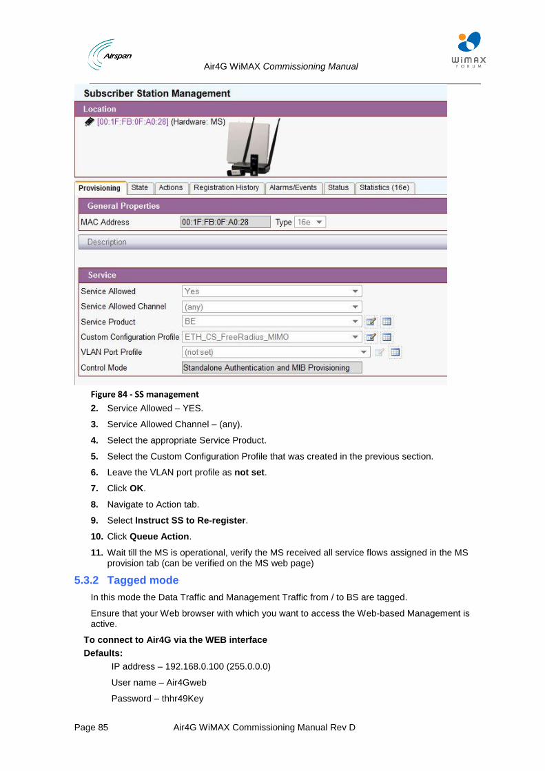
Air4G WiMAX Commissioning Manual
Page 85 Air4G WiMAX Commissioning Manual Rev D
Figure 84 - SS management
2. Service Allowed – YES.
3. Service Allowed Channel – (any).
4. Select the appropriate Service Product.
5. Select the Custom Configuration Profile that was created in the previous section.
6. Leave the VLAN port profile as not set.
7. Click OK.
8. Navigate to Action tab.
9. Select Instruct SS to Re-register.
10. Click Queue Action.
11. Wait till the MS is operational, verify the MS received all service flows assigned in the MS provision tab (can be verified on the MS web page)
5.3.2 Tagged mode
In this mode the Data Traffic and Management Traffic from / to BS are tagged.
Ensure that your Web browser with which you want to access the Web-based Management is active.
To connect to Air4G via the WEB interface
Defaults:
IP address – 192.168.0.100 (255.0.0.0)
User name – Air4Gweb
Password – thhr49Key
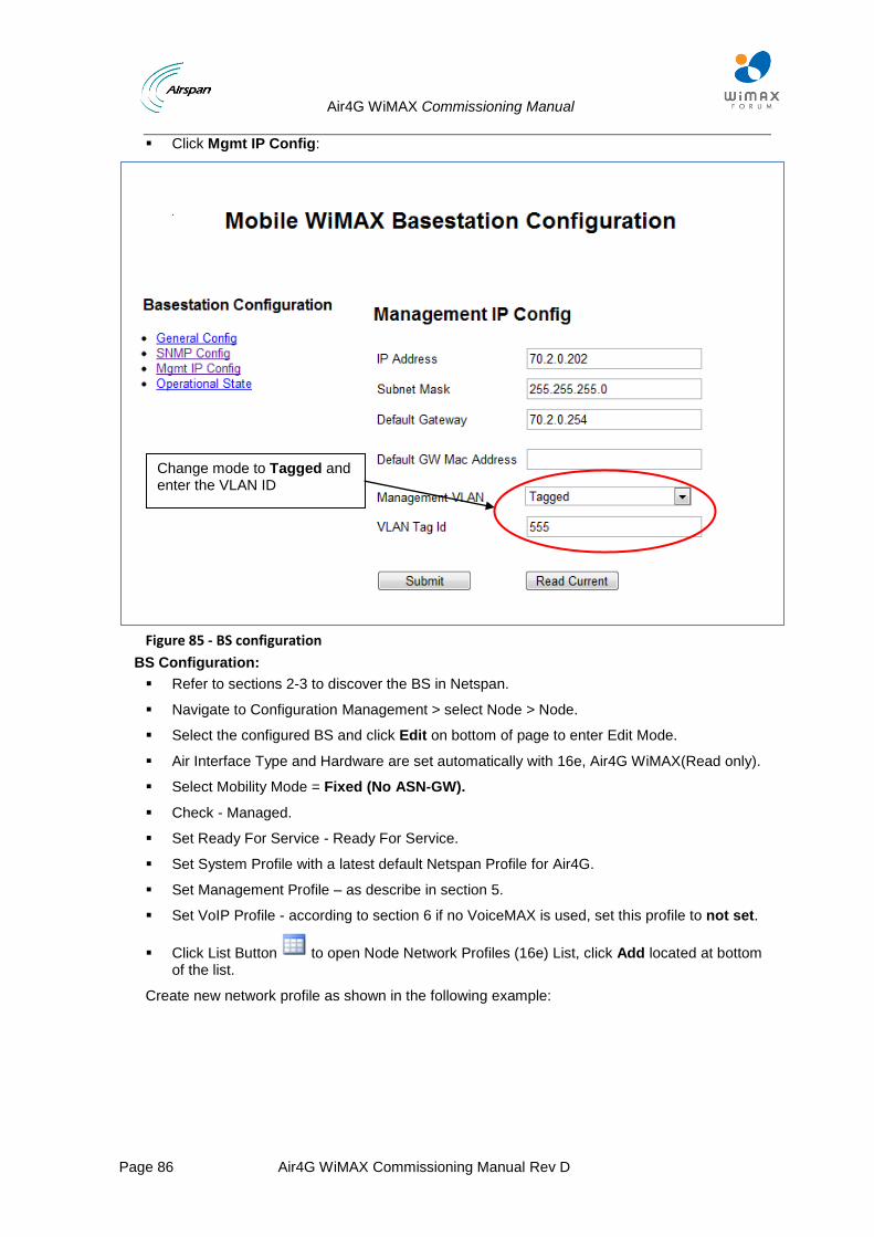
Air4G WiMAX Commissioning Manual
Page 86 Air4G WiMAX Commissioning Manual Rev D
Click Mgmt IP Config:
Figure 85 - BS configuration
BS Configuration:
Refer to sections 2-3 to discover the BS in Netspan.
Navigate to Configuration Management > select Node > Node.
Select the configured BS and click Edit on bottom of page to enter Edit Mode.
Air Interface Type and Hardware are set automatically with 16e, Air4G WiMAX(Read only).
Select Mobility Mode = Fixed (No ASN-GW).
Check - Managed.
Set Ready For Service - Ready For Service.
Set System Profile with a latest default Netspan Profile for Air4G.
Set Management Profile – as describe in section 5.
Set VoIP Profile - according to section 6 if no VoiceMAX is used, set this profile to not set.
Click List Button to open Node Network Profiles (16e) List, click Add located at bottom of the list.
Create new network profile as shown in the following example:
Change mode to Tagged and enter the VLAN ID
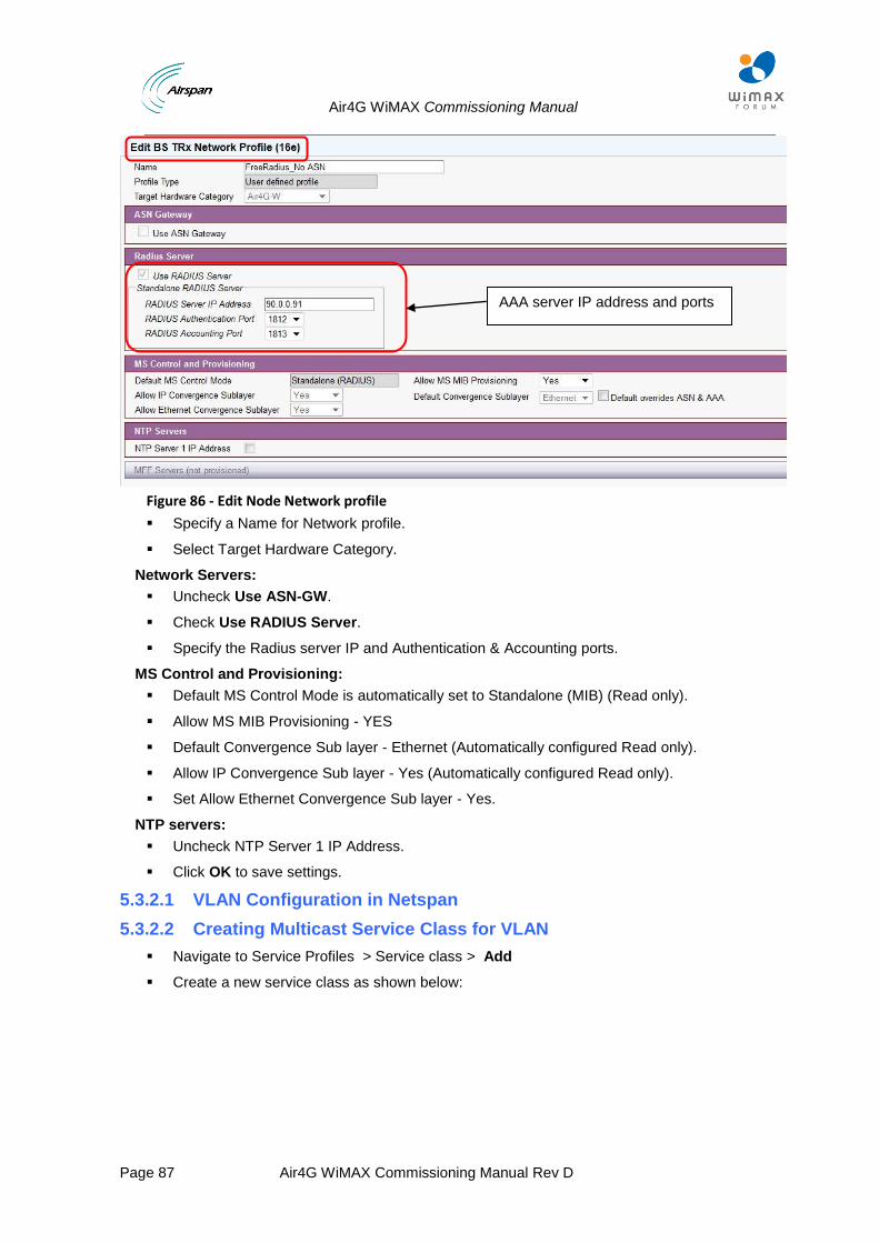
Air4G WiMAX Commissioning Manual
Page 87 Air4G WiMAX Commissioning Manual Rev D
Figure 86 - Edit Node Network profile
Specify a Name for Network profile.
Select Target Hardware Category.
Network Servers:
Uncheck Use ASN-GW.
Check Use RADIUS Server.
Specify the Radius server IP and Authentication & Accounting ports.
MS Control and Provisioning:
Default MS Control Mode is automatically set to Standalone (MIB) (Read only).
Allow MS MIB Provisioning - YES
Default Convergence Sub layer - Ethernet (Automatically configured Read only).
Allow IP Convergence Sub layer - Yes (Automatically configured Read only).
Set Allow Ethernet Convergence Sub layer - Yes.
NTP servers:
Uncheck NTP Server 1 IP Address.
Click OK to save settings.
5.3.2.1 VLAN Configuration in Netspan
5.3.2.2 Creating Multicast Service Class for VLAN
Navigate to Service Profiles > Service class > Add
Create a new service class as shown below:
AAA server IP address and ports
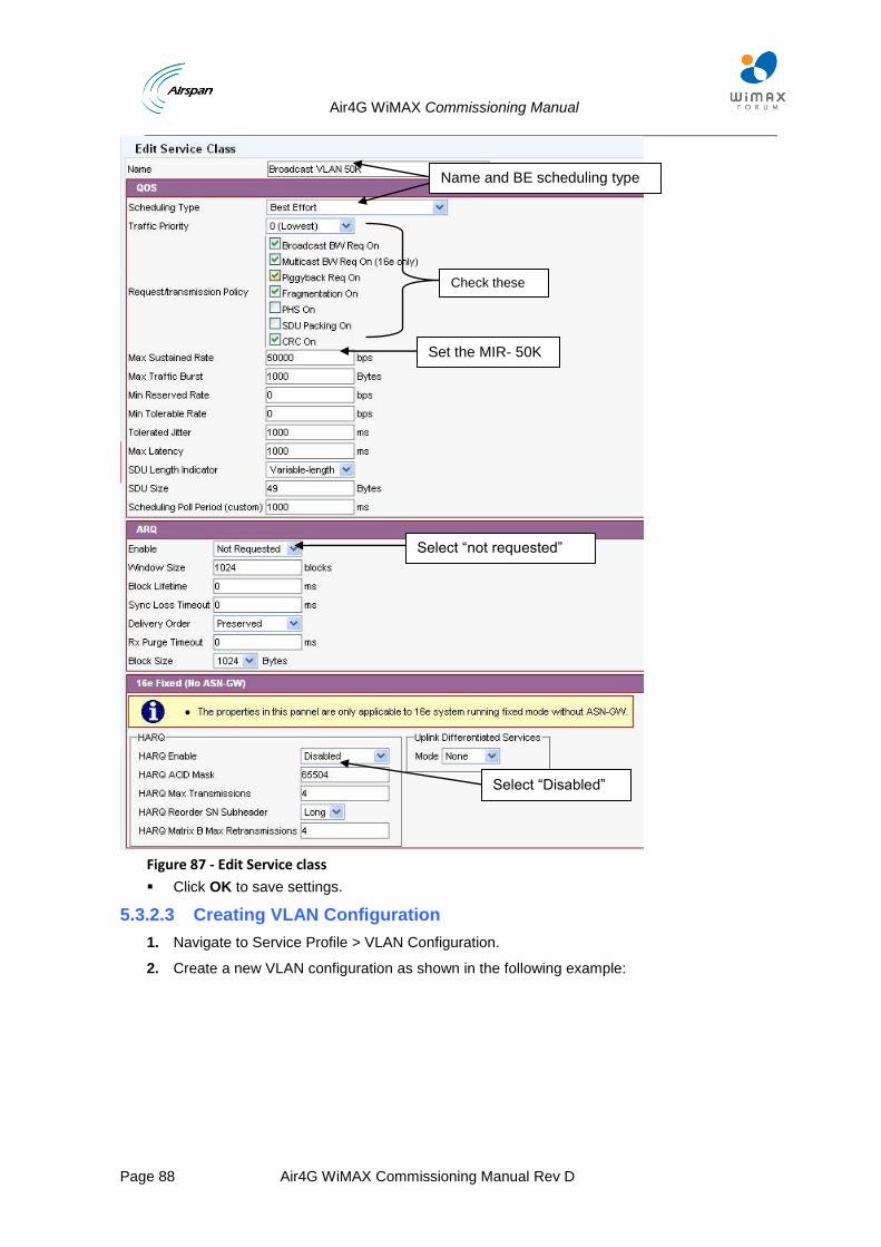
Air4G WiMAX Commissioning Manual
Page 88 Air4G WiMAX Commissioning Manual Rev D
Figure 87 - Edit Service class
Click OK to save settings.
5.3.2.3 Creating VLAN Configuration
1. Navigate to Service Profile > VLAN Configuration.
2. Create a new VLAN configuration as shown in the following example:
Name and BE scheduling type
Set the MIR- 50K
Select “Disabled”
Select “not requested”
Check these parameters

Air4G WiMAX Commissioning Manual
Page 89 Air4G WiMAX Commissioning Manual Rev D
Figure 88 - Edit VLAN configuration
3. Navigate to Services Profiles > select VLAN Configuration.
4. Set VLAN Id as needed.
5. Uncheck Single User.
6. Uncheck MAC Forced Forwarding.
7. Flood Unknown Traffic – Enabled.
8. Set Broadcast Mode to Multicast Group.
Click OK to save the VLAN configuration.
Configuration of one PVID for all MSs:
In this example we will configure the following:
VLAN 226 is the PVIDs for all MSs that are connected to the BS.
If BS management is required – no need to add it to BS network profile configuration.
Note: BS management VLAN the MS PVID should be different – it is not possible to use the same VLAN for both BS management and MS PVID.
To configure one PVID for all MSs perform the following steps:
1. Create one VLAN configuration - PVID.
2. Create BS Network profile that contains these VLANs.
3. Assign the profile to BS and MS.
Select Multicast Group
Set Broadcast Service class
Set name and VLAN ID
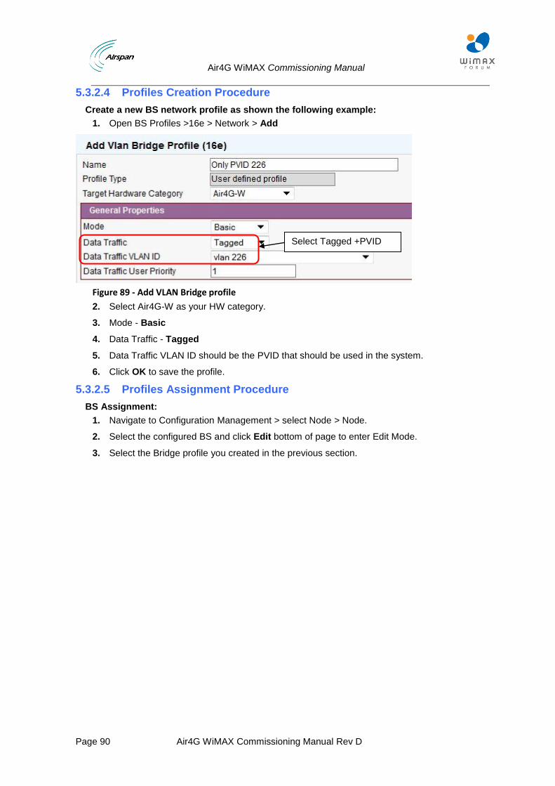
Air4G WiMAX Commissioning Manual
Page 90 Air4G WiMAX Commissioning Manual Rev D
5.3.2.4 Profiles Creation Procedure
Create a new BS network profile as shown the following example:
1. Open BS Profiles >16e > Network > Add
Figure 89 - Add VLAN Bridge profile
2. Select Air4G-W as your HW category.
3. Mode - Basic
4. Data Traffic - Tagged
5. Data Traffic VLAN ID should be the PVID that should be used in the system.
6. Click OK to save the profile.
5.3.2.5 Profiles Assignment Procedure
BS Assignment:
1. Navigate to Configuration Management > select Node > Node.
2. Select the configured BS and click Edit bottom of page to enter Edit Mode.
3. Select the Bridge profile you created in the previous section.
Select Tagged +PVID
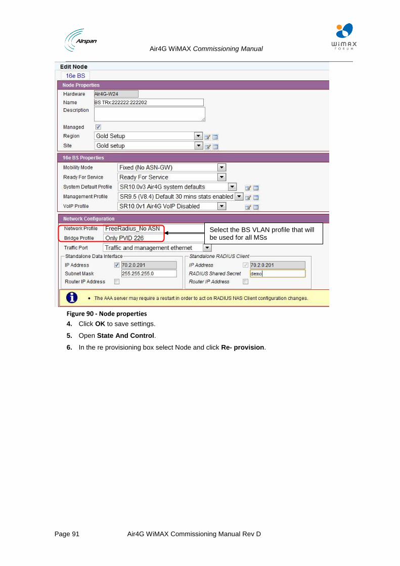
Air4G WiMAX Commissioning Manual
Page 91 Air4G WiMAX Commissioning Manual Rev D
Figure 90 - Node properties
4. Click OK to save settings.
5. Open State And Control.
6. In the re provisioning box select Node and click Re- provision.
Select the BS VLAN profile that will be used for all MSs
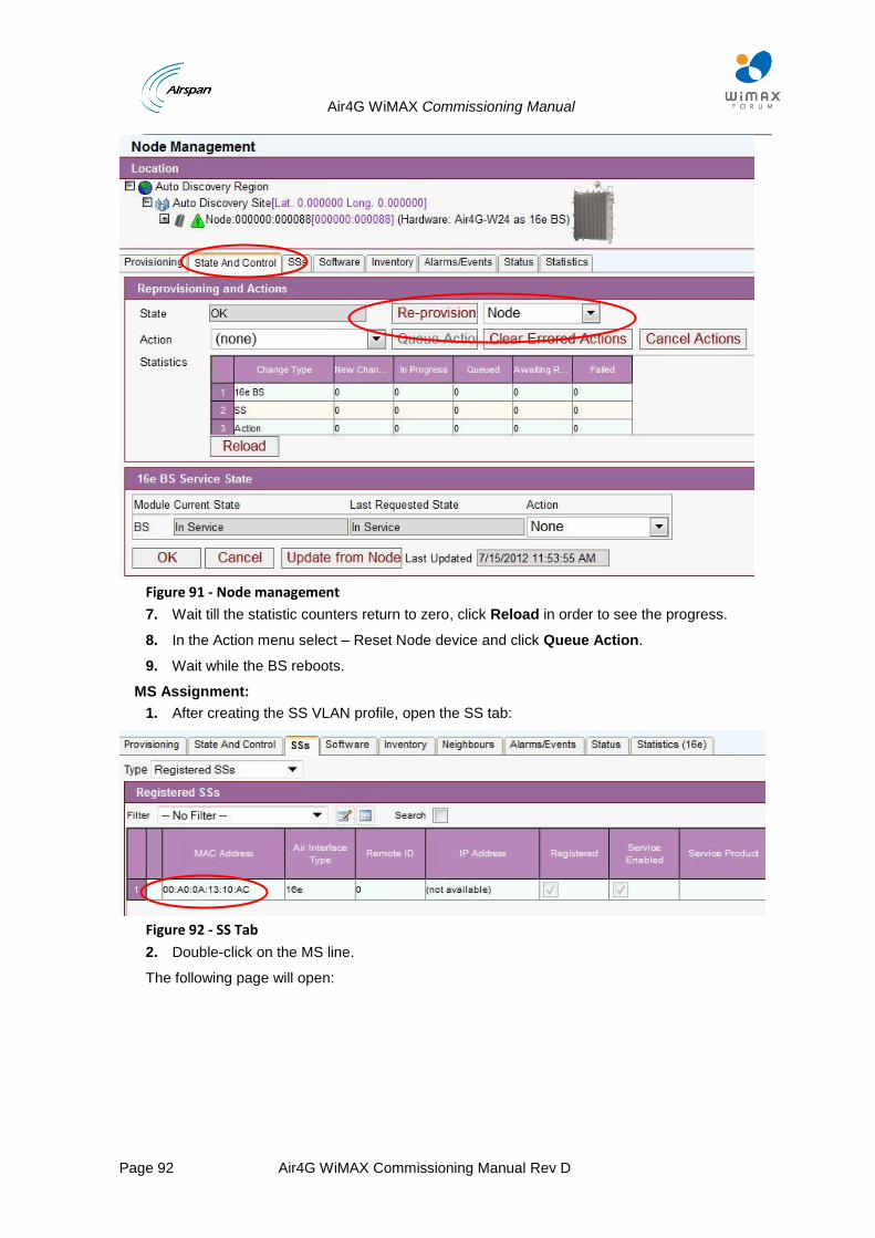
Air4G WiMAX Commissioning Manual
Page 92 Air4G WiMAX Commissioning Manual Rev D
Figure 91 - Node management
7. Wait till the statistic counters return to zero, click Reload in order to see the progress.
8. In the Action menu select – Reset Node device and click Queue Action.
9. Wait while the BS reboots.
MS Assignment:
1. After creating the SS VLAN profile, open the SS tab:
Figure 92 - SS Tab
2. Double-click on the MS line.
The following page will open:
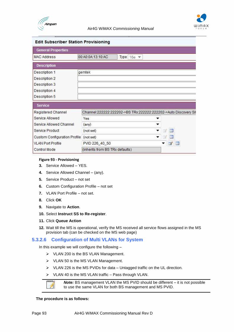
Air4G WiMAX Commissioning Manual
Page 93 Air4G WiMAX Commissioning Manual Rev D
Figure 93 - Provisioning
3. Service Allowed – YES.
4. Service Allowed Channel – (any).
5. Service Product – not set
6. Custom Configuration Profile – not set
7. VLAN Port Profile – not set.
8. Click OK
9. Navigate to Action.
10. Select Instruct SS to Re-register.
11. Click Queue Action
12. Wait till the MS is operational, verify the MS received all service flows assigned in the MS provision tab (can be checked on the MS web page)
5.3.2.6 Configuration of Multi VLANs for System
In this example we will configure the following –
VLAN 200 is the BS VLAN Management.
VLAN 50 is the MS VLAN Management.
VLAN 226 is the MS PVIDs for data – Untagged traffic on the UL direction.
VLAN 40 is the MS VLAN traffic – Pass through VLAN.
Note: BS management VLAN the MS PVID should be different – it is not possible to use the same VLAN for both BS management and MS PVID.
The procedure is as follows:
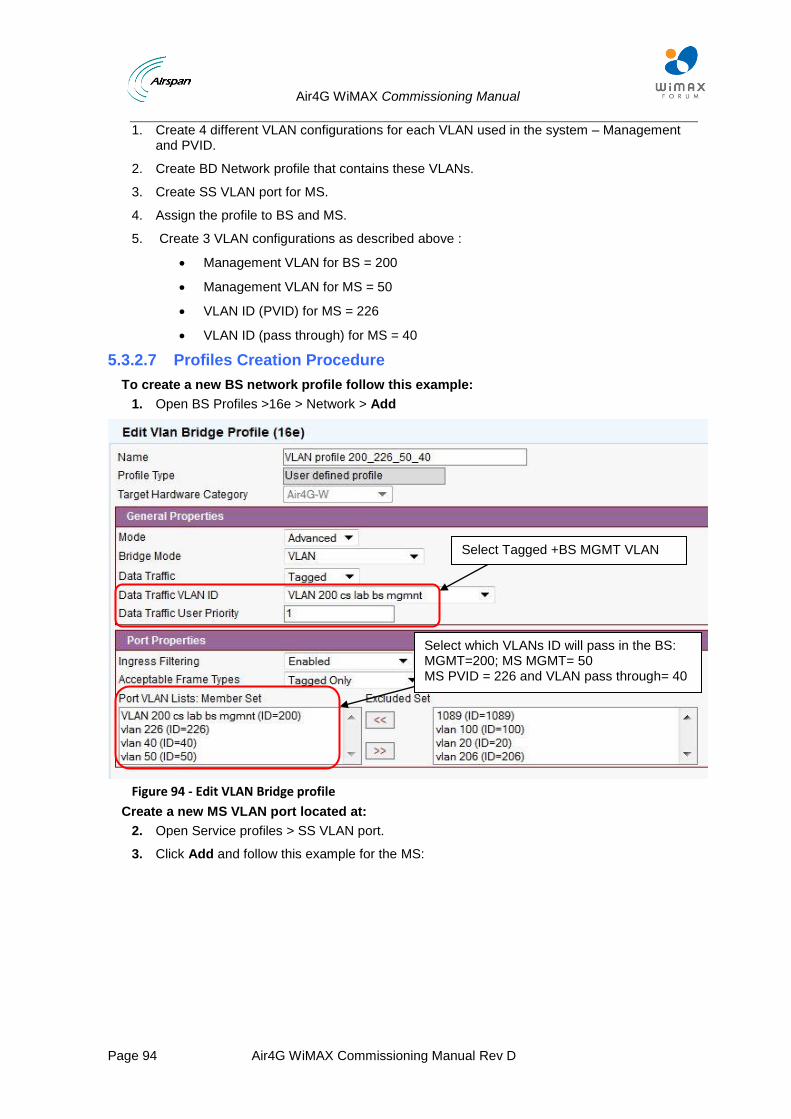
Air4G WiMAX Commissioning Manual
Page 94 Air4G WiMAX Commissioning Manual Rev D
1. Create 4 different VLAN configurations for each VLAN used in the system – Management and PVID.
2. Create BD Network profile that contains these VLANs.
3. Create SS VLAN port for MS.
4. Assign the profile to BS and MS.
5. Create 3 VLAN configurations as described above :
Management VLAN for BS = 200
Management VLAN for MS = 50
VLAN ID (PVID) for MS = 226
VLAN ID (pass through) for MS = 40
5.3.2.7 Profiles Creation Procedure
To create a new BS network profile follow this example:
1. Open BS Profiles >16e > Network > Add
Figure 94 - Edit VLAN Bridge profile
Create a new MS VLAN port located at:
2. Open Service profiles > SS VLAN port.
3. Click Add and follow this example for the MS:
Select Tagged +BS MGMT VLAN ID
Select which VLANs ID will pass in the BS: MGMT=200; MS MGMT= 50 MS PVID = 226 and VLAN pass through= 40
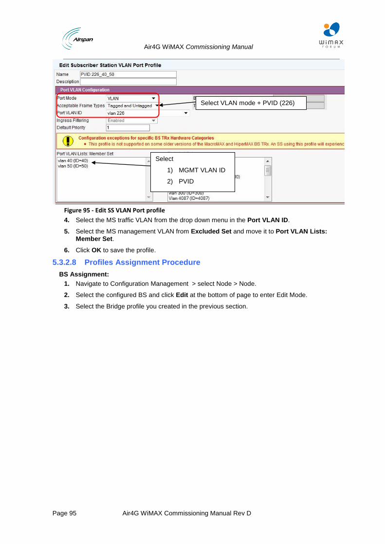
Air4G WiMAX Commissioning Manual
Page 95 Air4G WiMAX Commissioning Manual Rev D
Figure 95 - Edit SS VLAN Port profile
4. Select the MS traffic VLAN from the drop down menu in the Port VLAN ID.
5. Select the MS management VLAN from Excluded Set and move it to Port VLAN Lists: Member Set.
6. Click OK to save the profile.
5.3.2.8 Profiles Assignment Procedure
BS Assignment:
1. Navigate to Configuration Management > select Node > Node.
2. Select the configured BS and click Edit at the bottom of page to enter Edit Mode.
3. Select the Bridge profile you created in the previous section.
Select VLAN mode + PVID (226)
Select
1) MGMT VLAN ID
2) PVID
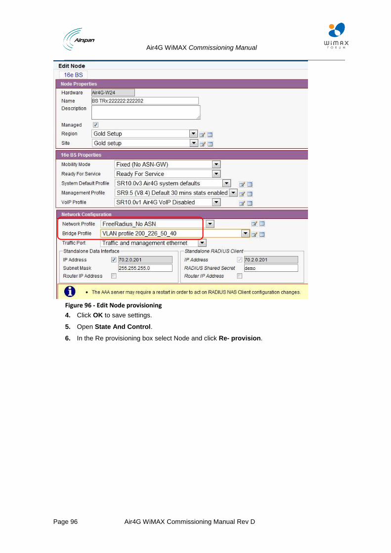
Air4G WiMAX Commissioning Manual
Page 96 Air4G WiMAX Commissioning Manual Rev D
Figure 96 - Edit Node provisioning
4. Click OK to save settings.
5. Open State And Control.
6. In the Re provisioning box select Node and click Re- provision.

Air4G WiMAX Commissioning Manual
Page 97 Air4G WiMAX Commissioning Manual Rev D
Figure 97 - Node management
7. Wait till the statistic counters return to zero, click Reload in order to see the progress.
8. In the Action drop down menu select – Reset Node Device and click Queue Action.
9. Wait while the BS reboots.
MS Assignment:
1. After creating the SS VLAN profile, open the SS tab:
Figure 98 - SS Tab
2. Double click on the MS line.
The following page will open:
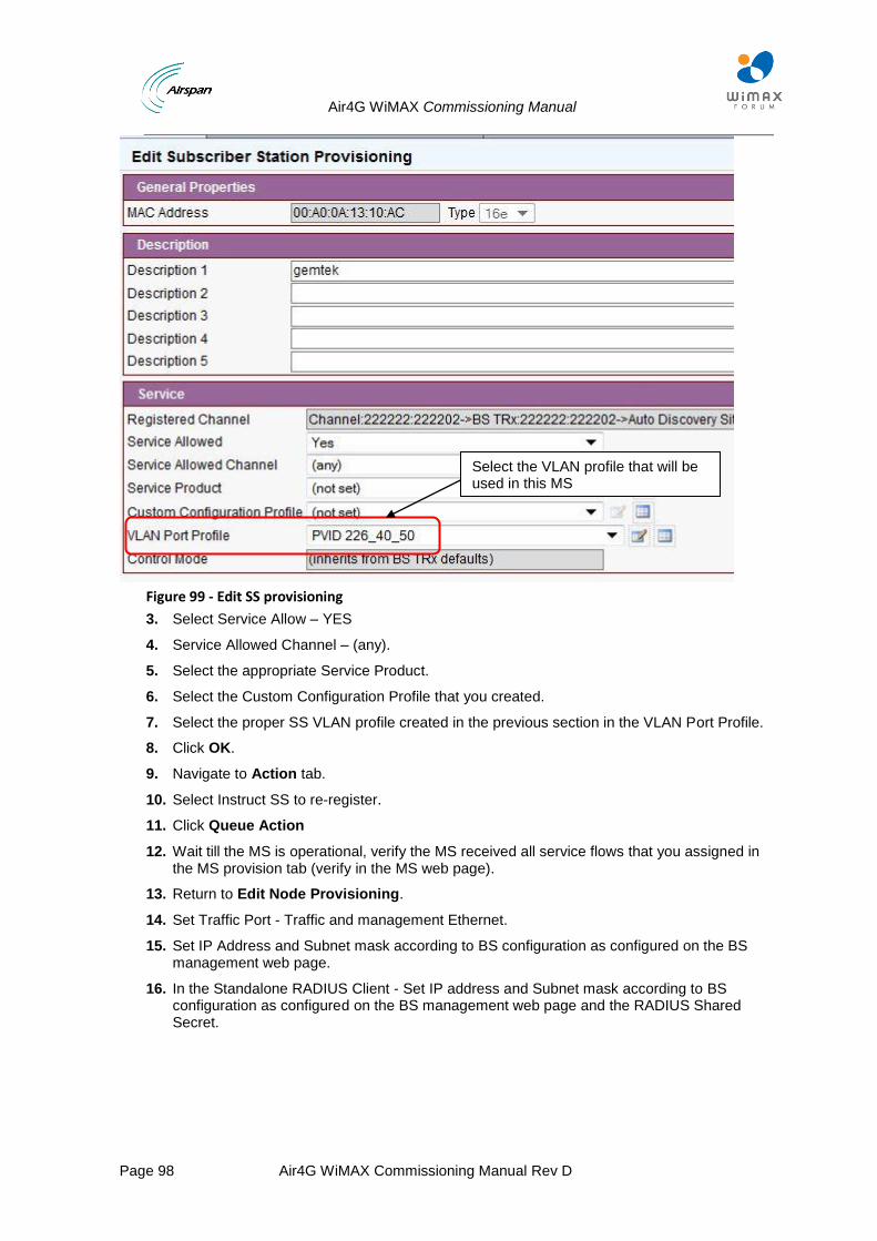
Air4G WiMAX Commissioning Manual
Page 98 Air4G WiMAX Commissioning Manual Rev D
Figure 99 - Edit SS provisioning
3. Select Service Allow – YES
4. Service Allowed Channel – (any).
5. Select the appropriate Service Product.
6. Select the Custom Configuration Profile that you created.
7. Select the proper SS VLAN profile created in the previous section in the VLAN Port Profile.
8. Click OK.
9. Navigate to Action tab.
10. Select Instruct SS to re-register.
11. Click Queue Action
12. Wait till the MS is operational, verify the MS received all service flows that you assigned in the MS provision tab (verify in the MS web page).
13. Return to Edit Node Provisioning.
14. Set Traffic Port - Traffic and management Ethernet.
15. Set IP Address and Subnet mask according to BS configuration as configured on the BS management web page.
16. In the Standalone RADIUS Client - Set IP address and Subnet mask according to BS configuration as configured on the BS management web page and the RADIUS Shared Secret.
Select the VLAN profile that will be used in this MS
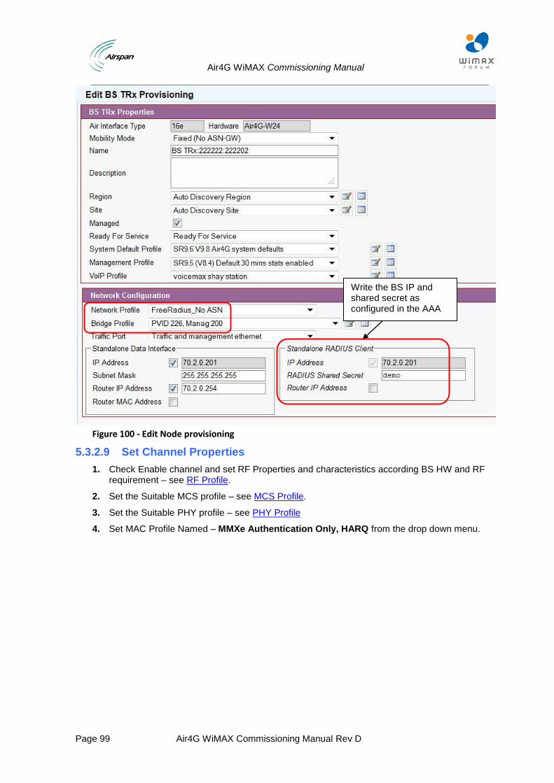
Air4G WiMAX Commissioning Manual
Page 99 Air4G WiMAX Commissioning Manual Rev D
Figure 100 - Edit Node provisioning
5.3.2.9 Set Channel Properties
1. Check Enable channel and set RF Properties and characteristics according BS HW and RF requirement – see RF Profile.
2. Set the Suitable MCS profile – see MCS Profile.
3. Set the Suitable PHY profile – see PHY Profile
4. Set MAC Profile Named – MMXe Authentication Only, HARQ from the drop down menu.
Write the BS IP and shared secret as configured in the AAA
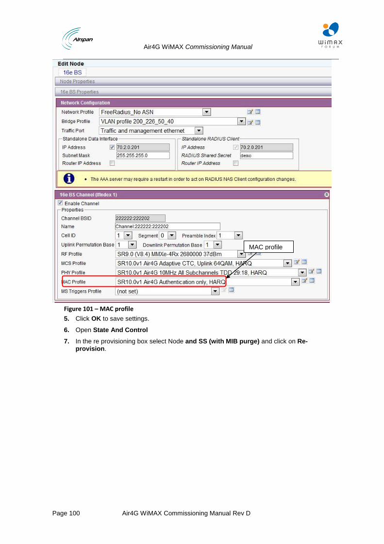
Air4G WiMAX Commissioning Manual
Page 100 Air4G WiMAX Commissioning Manual Rev D
Figure 101 – MAC profile
5. Click OK to save settings.
6. Open State And Control
7. In the re provisioning box select Node and SS (with MIB purge) and click on Re- provision.
MAC profile
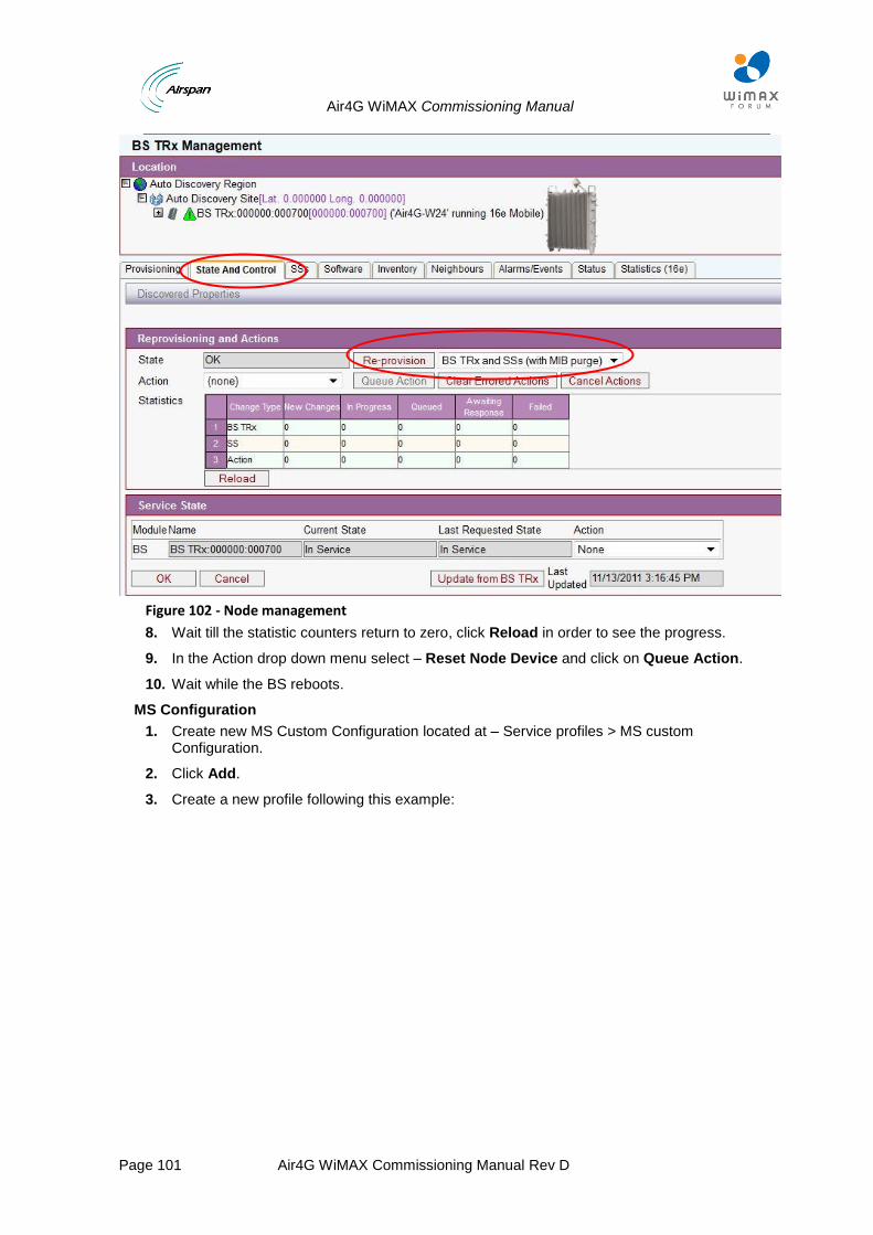
Air4G WiMAX Commissioning Manual
Page 101 Air4G WiMAX Commissioning Manual Rev D
Figure 102 - Node management
8. Wait till the statistic counters return to zero, click Reload in order to see the progress.
9. In the Action drop down menu select – Reset Node Device and click on Queue Action.
10. Wait while the BS reboots.
MS Configuration
1. Create new MS Custom Configuration located at – Service profiles > MS custom Configuration.
2. Click Add.
3. Create a new profile following this example:
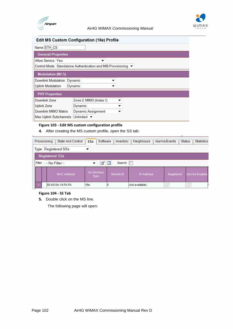
Air4G WiMAX Commissioning Manual
Page 102 Air4G WiMAX Commissioning Manual Rev D
Figure 103 - Edit MS custom configuration profile
4. After creating the MS custom profile, open the SS tab:
Figure 104 - SS Tab
5. Double click on the MS line.
The following page will open:
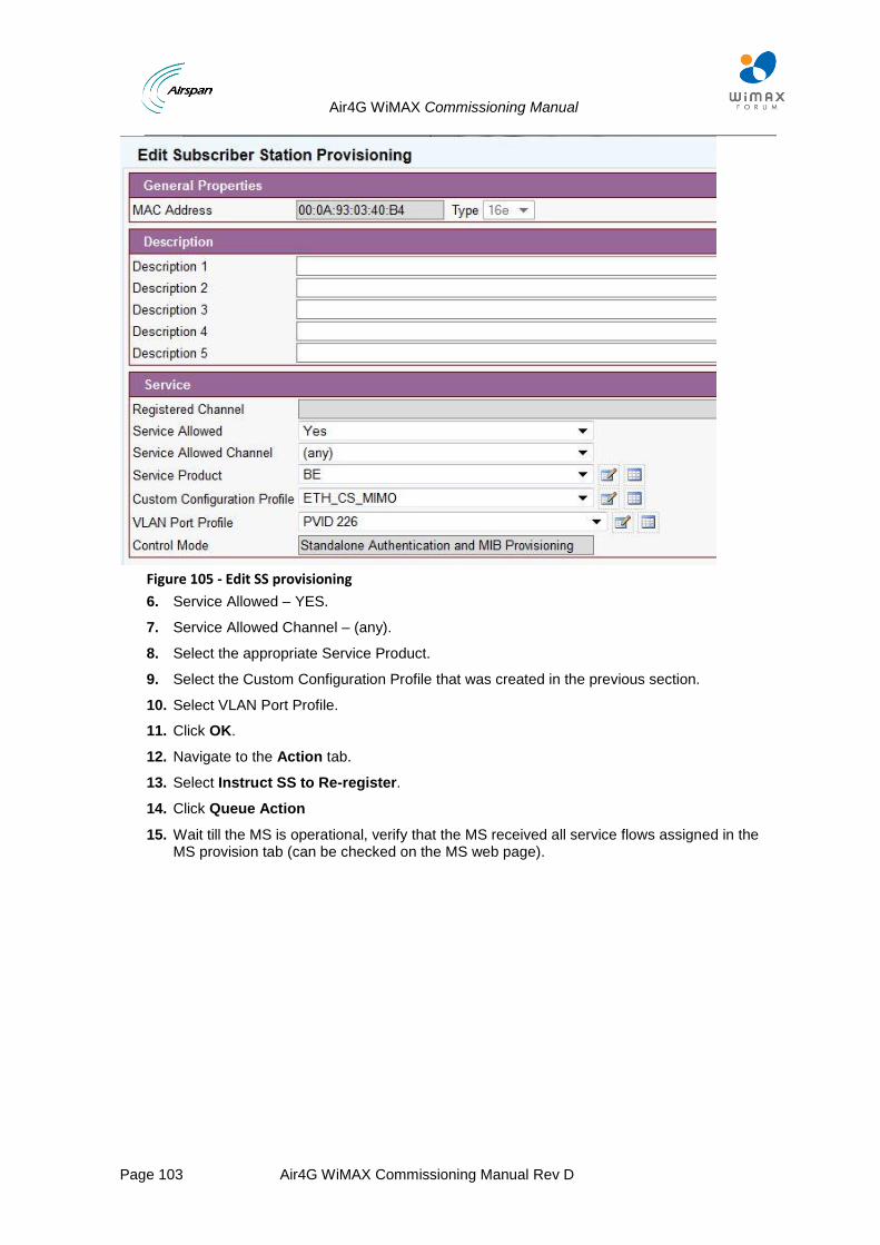
Air4G WiMAX Commissioning Manual
Page 103 Air4G WiMAX Commissioning Manual Rev D
Figure 105 - Edit SS provisioning
6. Service Allowed – YES.
7. Service Allowed Channel – (any).
8. Select the appropriate Service Product.
9. Select the Custom Configuration Profile that was created in the previous section.
10. Select VLAN Port Profile.
11. Click OK.
12. Navigate to the Action tab.
13. Select Instruct SS to Re-register.
14. Click Queue Action
15. Wait till the MS is operational, verify that the MS received all service flows assigned in the MS provision tab (can be checked on the MS web page).
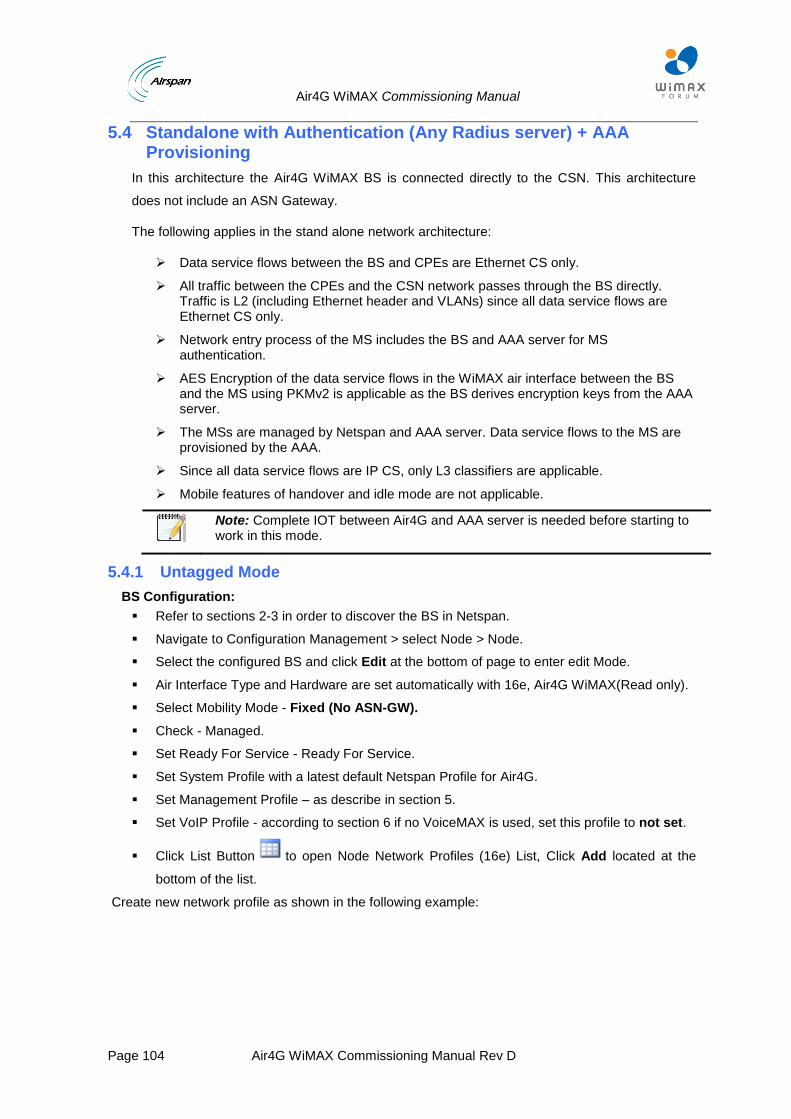
Air4G WiMAX Commissioning Manual
Page 104 Air4G WiMAX Commissioning Manual Rev D
5.4 Standalone with Authentication (Any Radius server) + AAA Provisioning
In this architecture the Air4G WiMAX BS is connected directly to the CSN. This architecture
does not include an ASN Gateway.
The following applies in the stand alone network architecture:
Data service flows between the BS and CPEs are Ethernet CS only.
All traffic between the CPEs and the CSN network passes through the BS directly. Traffic is L2 (including Ethernet header and VLANs) since all data service flows are Ethernet CS only.
Network entry process of the MS includes the BS and AAA server for MS authentication.
AES Encryption of the data service flows in the WiMAX air interface between the BS and the MS using PKMv2 is applicable as the BS derives encryption keys from the AAA server.
The MSs are managed by Netspan and AAA server. Data service flows to the MS are provisioned by the AAA.
Since all data service flows are IP CS, only L3 classifiers are applicable.
Mobile features of handover and idle mode are not applicable.
Note: Complete IOT between Air4G and AAA server is needed before starting to work in this mode.
5.4.1 Untagged Mode
BS Configuration:
Refer to sections 2-3 in order to discover the BS in Netspan.
Navigate to Configuration Management > select Node > Node.
Select the configured BS and click Edit at the bottom of page to enter edit Mode.
Air Interface Type and Hardware are set automatically with 16e, Air4G WiMAX(Read only).
Select Mobility Mode - Fixed (No ASN-GW).
Check - Managed.
Set Ready For Service - Ready For Service.
Set System Profile with a latest default Netspan Profile for Air4G.
Set Management Profile – as describe in section 5.
Set VoIP Profile - according to section 6 if no VoiceMAX is used, set this profile to not set.
Click List Button to open Node Network Profiles (16e) List, Click Add located at the
bottom of the list.
Create new network profile as shown in the following example:
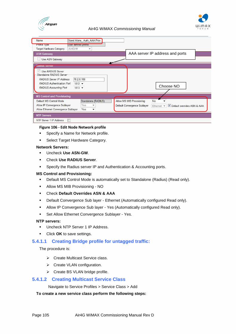
Air4G WiMAX Commissioning Manual
Page 105 Air4G WiMAX Commissioning Manual Rev D
Figure 106 - Edit Node Network profile
Specify a Name for Network profile.
Select Target Hardware Category.
Network Servers:
Uncheck Use ASN-GW.
Check Use RADIUS Server.
Specify the Radius server IP and Authentication & Accounting ports.
MS Control and Provisioning:
Default MS Control Mode is automatically set to Standalone (Radius) (Read only).
Allow MS MIB Provisioning - NO
Check Default Overrides ASN & AAA
Default Convergence Sub layer - Ethernet (Automatically configured Read only).
Allow IP Convergence Sub layer - Yes (Automatically configured Read only).
Set Allow Ethernet Convergence Sublayer - Yes.
NTP servers:
Uncheck NTP Server 1 IP Address.
Click OK to save settings.
5.4.1.1 Creating Bridge profile for untagged traffic:
The procedure is:
Create Multicast Service class.
Create VLAN configuration.
Create BS VLAN bridge profile.
5.4.1.2 Creating Multicast Service Class
Navigate to Service Profiles > Service Class > Add
To create a new service class perform the following steps:
AAA server IP address and ports
Choose NO
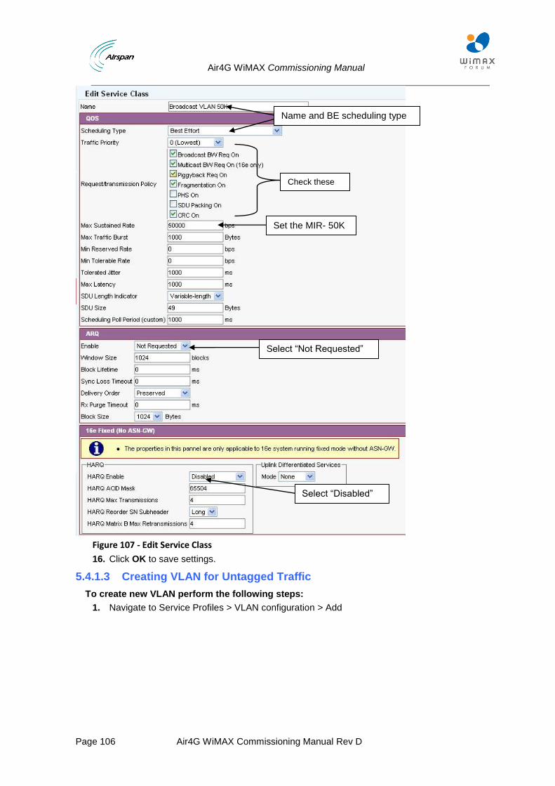
Air4G WiMAX Commissioning Manual
Page 106 Air4G WiMAX Commissioning Manual Rev D
Figure 107 - Edit Service Class
16. Click OK to save settings.
5.4.1.3 Creating VLAN for Untagged Traffic
To create new VLAN perform the following steps:
1. Navigate to Service Profiles > VLAN configuration > Add
Name and BE scheduling type
Set the MIR- 50K
Select “Disabled”
Select “Not Requested”
Check these parameters
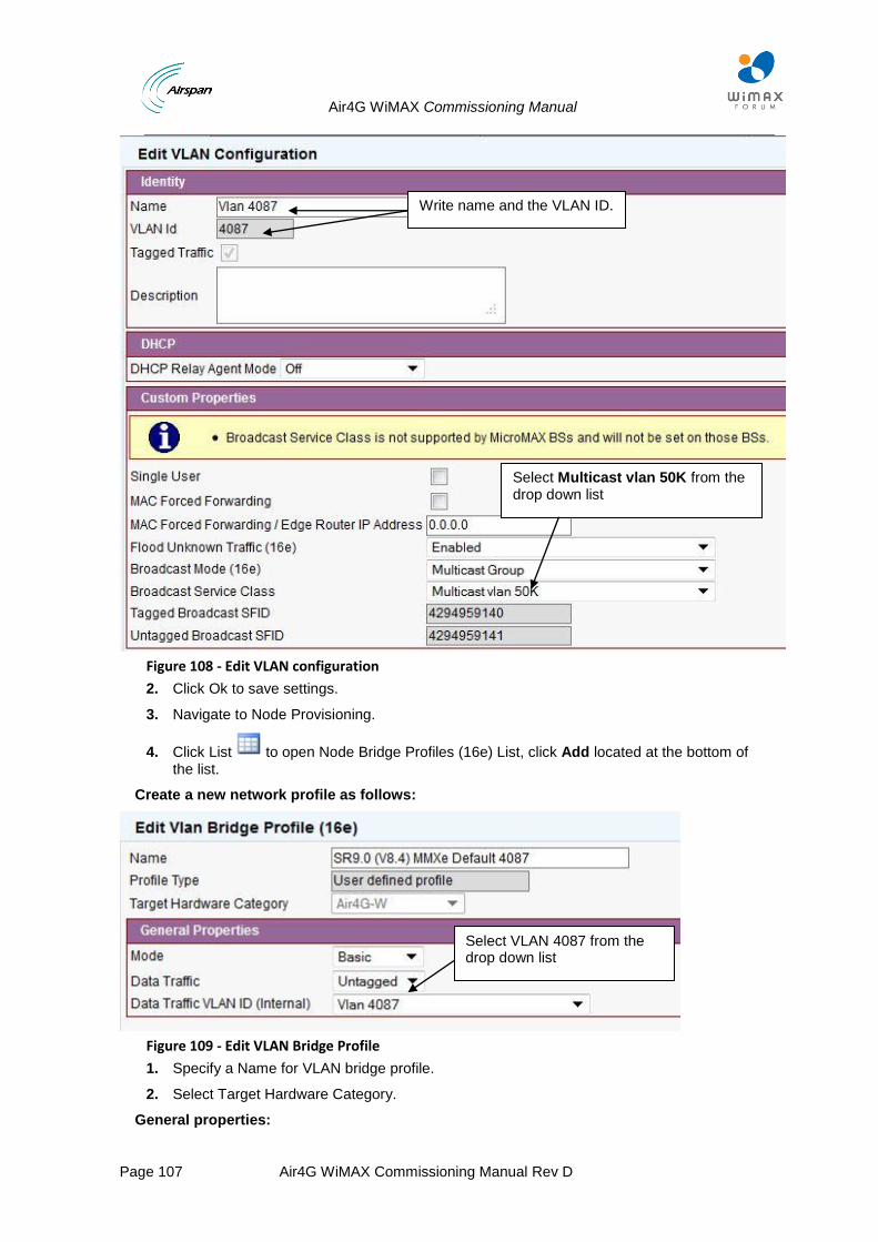
Air4G WiMAX Commissioning Manual
Page 107 Air4G WiMAX Commissioning Manual Rev D
Figure 108 - Edit VLAN configuration
2. Click Ok to save settings.
3. Navigate to Node Provisioning.
4. Click List to open Node Bridge Profiles (16e) List, click Add located at the bottom of the list.
Create a new network profile as follows:
Figure 109 - Edit VLAN Bridge Profile
1. Specify a Name for VLAN bridge profile.
2. Select Target Hardware Category.
General properties:
Select VLAN 4087 from the drop down list
Select Multicast vlan 50K from the drop down list
Write name and the VLAN ID.
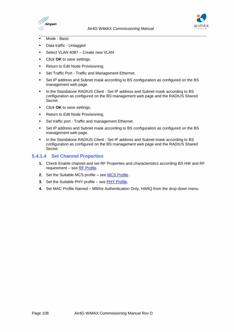
Air4G WiMAX Commissioning Manual
Page 108 Air4G WiMAX Commissioning Manual Rev D
Mode - Basic
Data traffic - Untagged
Select VLAN 4087 – Create new VLAN
Click OK to save settings.
Return to Edit Node Provisioning.
Set Traffic Port - Traffic and Management Ethernet.
Set IP address and Subnet mask according to BS configuration as configured on the BS management web page.
In the Standalone RADIUS Client - Set IP address and Subnet mask according to BS configuration as configured on the BS management web page and the RADIUS Shared Secret.
Click OK to save settings.
Return to Edit Node Provisioning.
Set traffic port - Traffic and management Ethernet.
Set IP address and Subnet mask according to BS configuration as configured on the BS management web page.
In the Standalone RADIUS Client - Set IP address and Subnet mask according to BS configuration as configured on the BS management web page and the RADIUS Shared Secret.
5.4.1.4 Set Channel Properties
1. Check Enable channel and set RF Properties and characteristics according BS HW and RF requirement – see RF Profile.
2. Set the Suitable MCS profile – see MCS Profile .
3. Set the Suitable PHY profile – see PHY Profile.
4. Set MAC Profile Named – MMXe Authentication Only, HARQ from the drop down menu.
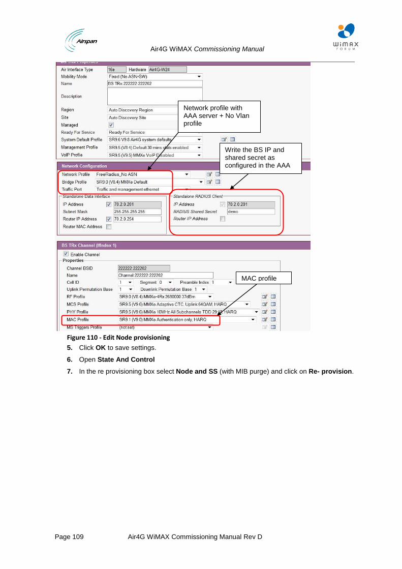
Air4G WiMAX Commissioning Manual
Page 109 Air4G WiMAX Commissioning Manual Rev D
Figure 110 - Edit Node provisioning
5. Click OK to save settings.
6. Open State And Control
7. In the re provisioning box select Node and SS (with MIB purge) and click on Re- provision.
Write the BS IP and shared secret as configured in the AAA
MAC profile
Network profile with AAA server + No Vlan profile
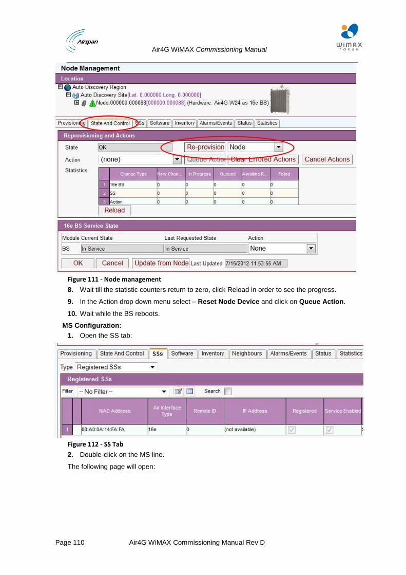
Air4G WiMAX Commissioning Manual
Page 110 Air4G WiMAX Commissioning Manual Rev D
Figure 111 - Node management
8. Wait till the statistic counters return to zero, click Reload in order to see the progress.
9. In the Action drop down menu select – Reset Node Device and click on Queue Action.
10. Wait while the BS reboots.
MS Configuration:
1. Open the SS tab:
Figure 112 - SS Tab
2. Double-click on the MS line.
The following page will open:
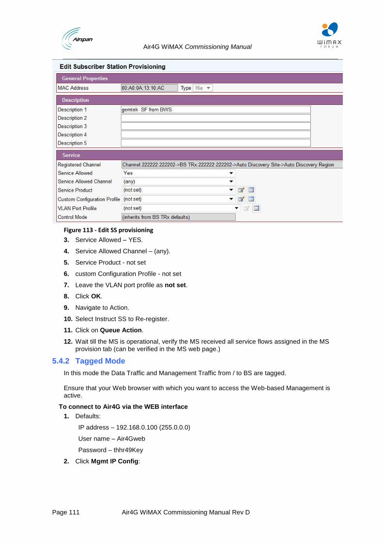
Air4G WiMAX Commissioning Manual
Page 111 Air4G WiMAX Commissioning Manual Rev D
Figure 113 - Edit SS provisioning
3. Service Allowed – YES.
4. Service Allowed Channel – (any).
5. Service Product - not set
6. custom Configuration Profile - not set
7. Leave the VLAN port profile as not set.
8. Click OK.
9. Navigate to Action.
10. Select Instruct SS to Re-register.
11. Click on Queue Action.
12. Wait till the MS is operational, verify the MS received all service flows assigned in the MS provision tab (can be verified in the MS web page.)
5.4.2 Tagged Mode
In this mode the Data Traffic and Management Traffic from / to BS are tagged.
Ensure that your Web browser with which you want to access the Web-based Management is active.
To connect to Air4G via the WEB interface
1. Defaults:
IP address – 192.168.0.100 (255.0.0.0)
User name – Air4Gweb
Password – thhr49Key
2. Click Mgmt IP Config:
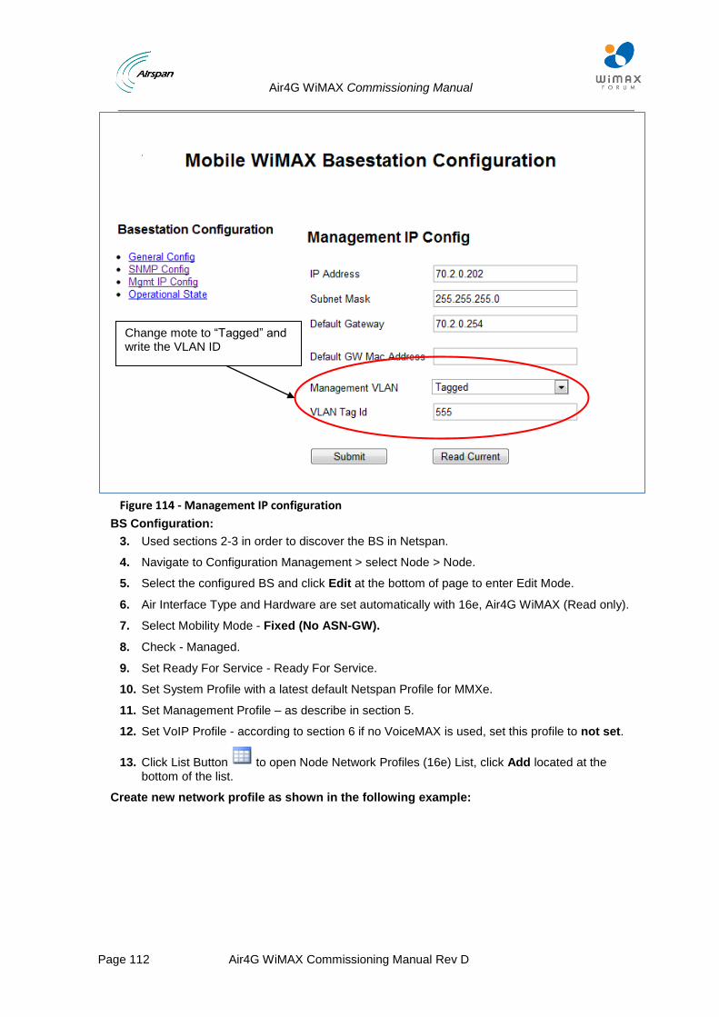
Air4G WiMAX Commissioning Manual
Page 112 Air4G WiMAX Commissioning Manual Rev D
Figure 114 - Management IP configuration
BS Configuration:
3. Used sections 2-3 in order to discover the BS in Netspan.
4. Navigate to Configuration Management > select Node > Node.
5. Select the configured BS and click Edit at the bottom of page to enter Edit Mode.
6. Air Interface Type and Hardware are set automatically with 16e, Air4G WiMAX (Read only).
7. Select Mobility Mode - Fixed (No ASN-GW).
8. Check - Managed.
9. Set Ready For Service - Ready For Service.
10. Set System Profile with a latest default Netspan Profile for MMXe.
11. Set Management Profile – as describe in section 5.
12. Set VoIP Profile - according to section 6 if no VoiceMAX is used, set this profile to not set.
13. Click List Button to open Node Network Profiles (16e) List, click Add located at the bottom of the list.
Create new network profile as shown in the following example:
Change mote to “Tagged” and write the VLAN ID
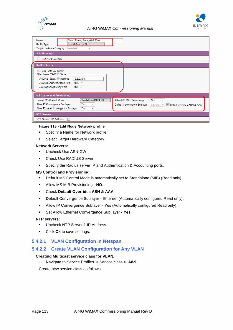
Air4G WiMAX Commissioning Manual
Page 113 Air4G WiMAX Commissioning Manual Rev D
Figure 115 - Edit Node Network profile
Specify a Name for Network profile.
Select Target Hardware Category.
Network Servers:
Uncheck Use ASN-GW.
Check Use RADIUS Server.
Specify the Radius server IP and Authentication & Accounting ports.
MS Control and Provisioning:
Default MS Control Mode is automatically set to Standalone (MIB) (Read only).
Allow MS MIB Provisioning - NO.
Check Default Overrides ASN & AAA
Default Convergence Sublayer - Ethernet (Automatically configured Read only).
Allow IP Convergence Sublayer - Yes (Automatically configured Read only).
Set Allow Ethernet Convergence Sub layer - Yes.
NTP servers:
Uncheck NTP Server 1 IP Address.
Click Ok to save settings.
5.4.2.1 VLAN Configuration in Netspan
5.4.2.2 Create VLAN Configuration for Any VLAN
Creating Multicast service class for VLAN.
1. Navigate to Service Profiles > Service class > Add
Create new service class as follows:
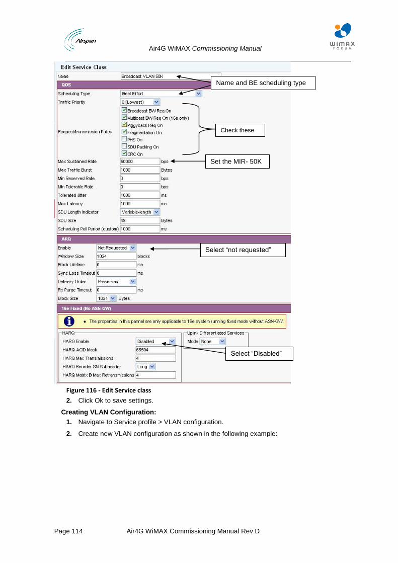
Air4G WiMAX Commissioning Manual
Page 114 Air4G WiMAX Commissioning Manual Rev D
Figure 116 - Edit Service class
2. Click Ok to save settings.
Creating VLAN Configuration:
1. Navigate to Service profile > VLAN configuration.
2. Create new VLAN configuration as shown in the following example:
Name and BE scheduling type
Set the MIR- 50K
Select “Disabled”
Select “not requested”
Check these parameters
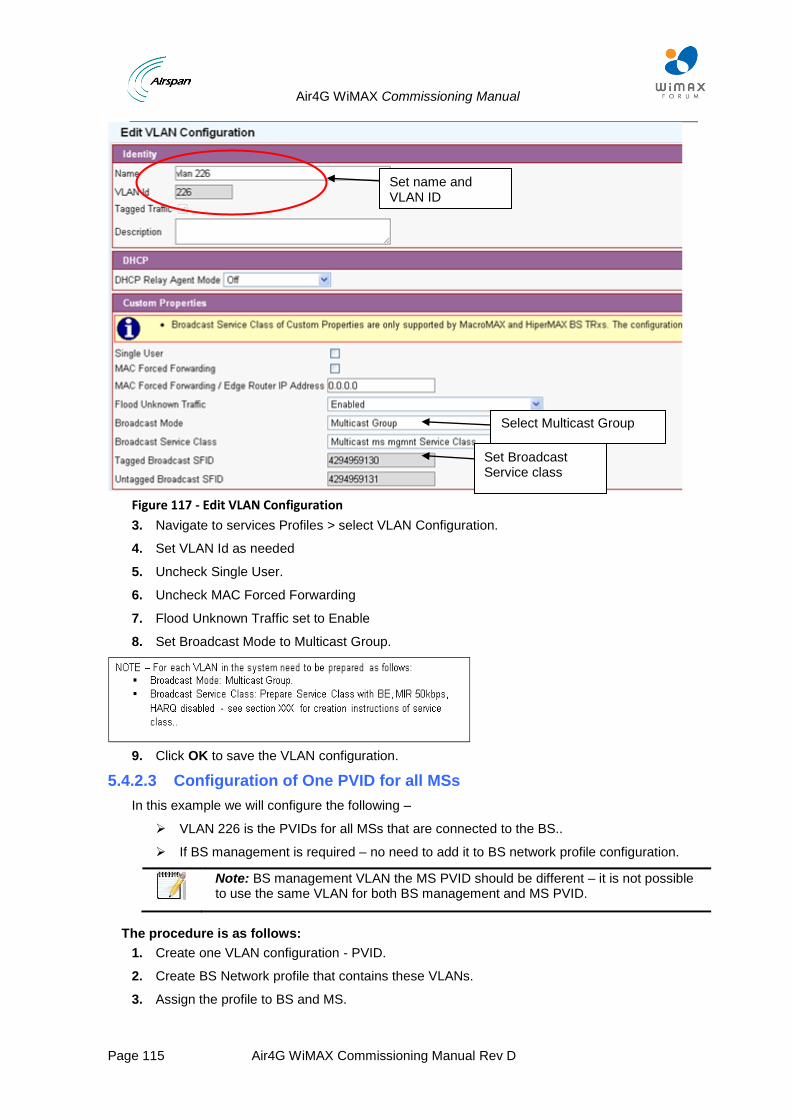
Air4G WiMAX Commissioning Manual
Page 115 Air4G WiMAX Commissioning Manual Rev D
Figure 117 - Edit VLAN Configuration
3. Navigate to services Profiles > select VLAN Configuration.
4. Set VLAN Id as needed
5. Uncheck Single User.
6. Uncheck MAC Forced Forwarding
7. Flood Unknown Traffic set to Enable
8. Set Broadcast Mode to Multicast Group.
9. Click OK to save the VLAN configuration.
5.4.2.3 Configuration of One PVID for all MSs
In this example we will configure the following –
VLAN 226 is the PVIDs for all MSs that are connected to the BS..
If BS management is required – no need to add it to BS network profile configuration.
Note: BS management VLAN the MS PVID should be different – it is not possible to use the same VLAN for both BS management and MS PVID.
The procedure is as follows:
1. Create one VLAN configuration - PVID.
2. Create BS Network profile that contains these VLANs.
3. Assign the profile to BS and MS.
Set name and VLAN ID
Set Broadcast Service class
Select Multicast Group

Air4G WiMAX Commissioning Manual
Page 116 Air4G WiMAX Commissioning Manual Rev D
5.4.2.4 Profiles Creation Procedure
Create a new BS network profile as shown in the following the example:
1. Open BS Profiles >16e > Network > Add
Figure 118 - Add VLAN bridge profile
2. Select Air4G WiMAXas your HW category.
3. Mode - Basic.
4. Data Traffic - Tagged.
5. Data traffic VLAN ID should be the PVID that should be used in the system.
6. Click OK to save the profile.
5.4.2.5 Profiles Assignment Procedure
BS Assignment:
1. Navigate to Configuration Management > select Node > Node.
2. Select the configured BS and click Edit at the bottom of page to enter Edit Mode.
3. Select the Bridge profile you created in the previous section.
Select Tagged +PVID
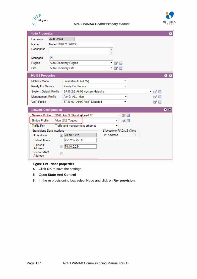
Air4G WiMAX Commissioning Manual
Page 117 Air4G WiMAX Commissioning Manual Rev D
Figure 119 - Node properties
4. Click OK to save the settings.
5. Open State And Control
6. In the re provisioning box select Node and click on Re- provision.
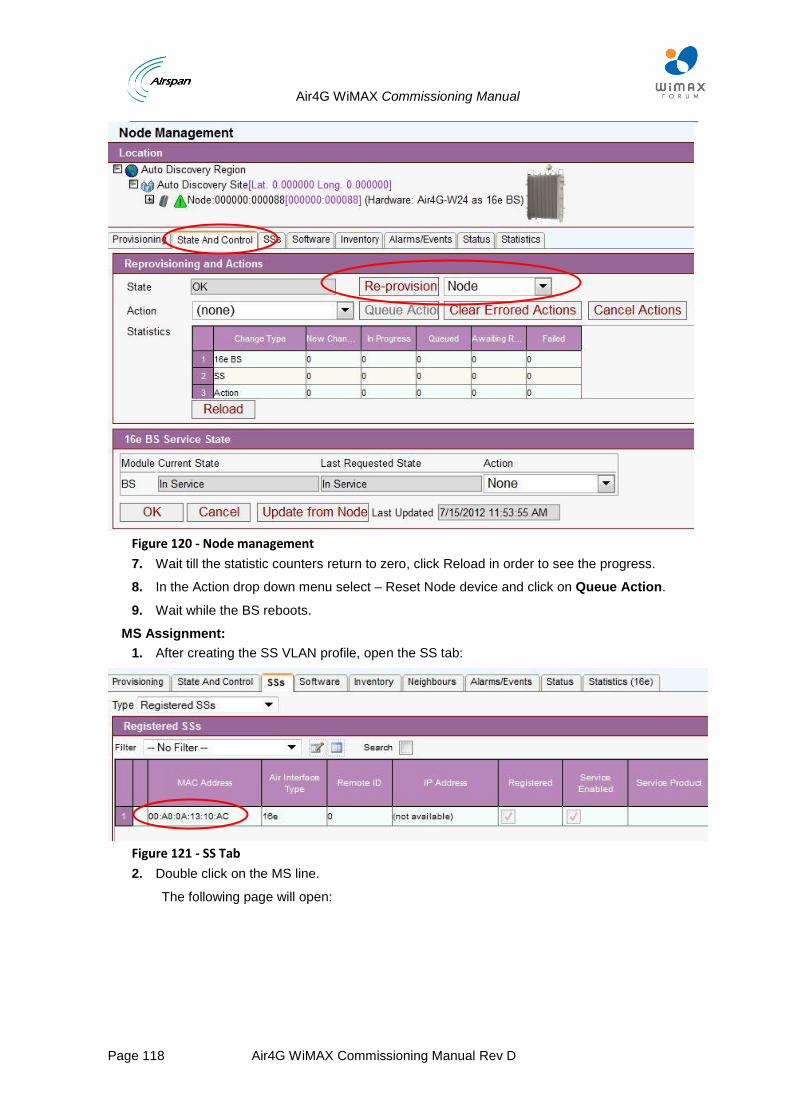
Air4G WiMAX Commissioning Manual
Page 118 Air4G WiMAX Commissioning Manual Rev D
Figure 120 - Node management
7. Wait till the statistic counters return to zero, click Reload in order to see the progress.
8. In the Action drop down menu select – Reset Node device and click on Queue Action.
9. Wait while the BS reboots.
MS Assignment:
1. After creating the SS VLAN profile, open the SS tab:
Figure 121 - SS Tab
2. Double click on the MS line.
The following page will open:
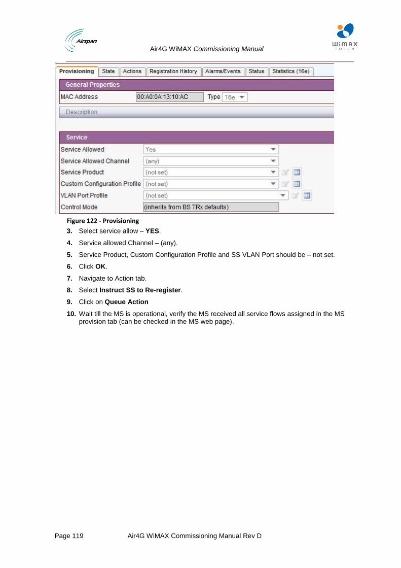
Air4G WiMAX Commissioning Manual
Page 119 Air4G WiMAX Commissioning Manual Rev D
Figure 122 - Provisioning
3. Select service allow – YES.
4. Service allowed Channel – (any).
5. Service Product, Custom Configuration Profile and SS VLAN Port should be – not set.
6. Click OK.
7. Navigate to Action tab.
8. Select Instruct SS to Re-register.
9. Click on Queue Action
10. Wait till the MS is operational, verify the MS received all service flows assigned in the MS provision tab (can be checked in the MS web page).
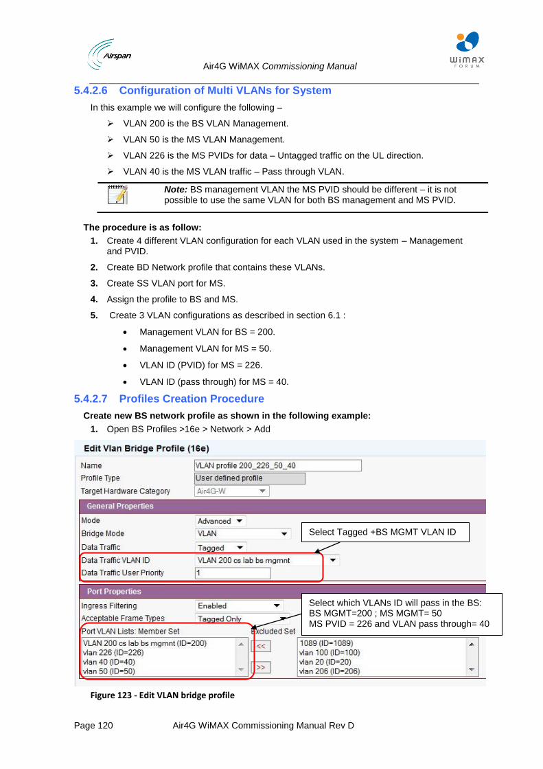
Air4G WiMAX Commissioning Manual
Page 120 Air4G WiMAX Commissioning Manual Rev D
5.4.2.6 Configuration of Multi VLANs for System
In this example we will configure the following –
VLAN 200 is the BS VLAN Management.
VLAN 50 is the MS VLAN Management.
VLAN 226 is the MS PVIDs for data – Untagged traffic on the UL direction.
VLAN 40 is the MS VLAN traffic – Pass through VLAN.
Note: BS management VLAN the MS PVID should be different – it is not possible to use the same VLAN for both BS management and MS PVID.
The procedure is as follow:
1. Create 4 different VLAN configuration for each VLAN used in the system – Management and PVID.
2. Create BD Network profile that contains these VLANs.
3. Create SS VLAN port for MS.
4. Assign the profile to BS and MS.
5. Create 3 VLAN configurations as described in section 6.1 :
Management VLAN for BS = 200.
Management VLAN for MS = 50.
VLAN ID (PVID) for MS = 226.
VLAN ID (pass through) for MS = 40.
5.4.2.7 Profiles Creation Procedure
Create new BS network profile as shown in the following example:
1. Open BS Profiles >16e > Network > Add
Figure 123 - Edit VLAN bridge profile
Select Tagged +BS MGMT VLAN ID
Select which VLANs ID will pass in the BS: BS MGMT=200 ; MS MGMT= 50 MS PVID = 226 and VLAN pass through= 40
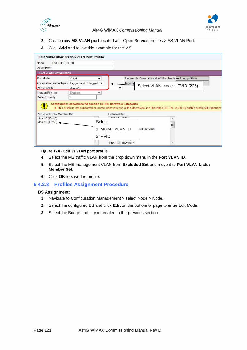
Air4G WiMAX Commissioning Manual
Page 121 Air4G WiMAX Commissioning Manual Rev D
2. Create new MS VLAN port located at – Open Service profiles > SS VLAN Port.
3. Click Add and follow this example for the MS
Figure 124 - Edit Ss VLAN port profile
4. Select the MS traffic VLAN from the drop down menu in the Port VLAN ID.
5. Select the MS management VLAN from Excluded Set and move it to Port VLAN Lists: Member Set.
6. Click OK to save the profile.
5.4.2.8 Profiles Assignment Procedure
BS Assignment:
1. Navigate to Configuration Management > select Node > Node.
2. Select the configured BS and click Edit on the bottom of page to enter Edit Mode.
3. Select the Bridge profile you created in the previous section.
Select VLAN mode + PVID (226)
Select
1. MGMT VLAN ID
2. PVID
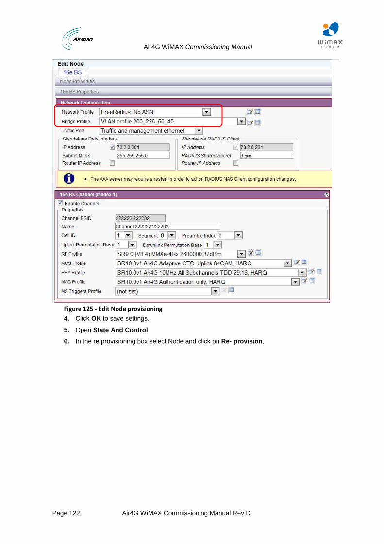
Air4G WiMAX Commissioning Manual
Page 122 Air4G WiMAX Commissioning Manual Rev D
Figure 125 - Edit Node provisioning
4. Click OK to save settings.
5. Open State And Control
6. In the re provisioning box select Node and click on Re- provision.

Air4G WiMAX Commissioning Manual
Page 123 Air4G WiMAX Commissioning Manual Rev D
Figure 126 - Node management
7. Wait till the statistic counters return to zero, click Reload in order to see the progress.
8. In the Action drop down menu select – reset Node device and click on Queue Action.
9. Wait while the BS reboots.
MS Assignment:
1. After creating the SS VLAN profile, open the SS tab:
Figure 127 - SS Tab
2. Double click on the MS line.
The following page will open:
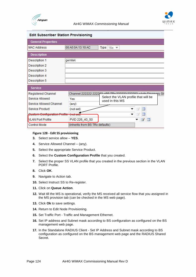
Air4G WiMAX Commissioning Manual
Page 124 Air4G WiMAX Commissioning Manual Rev D
Figure 128 - Edit SS provisioning
3. Select service allow – YES.
4. Service Allowed Channel – (any).
5. Select the appropriate Service Product.
6. Select the Custom Configuration Profile that you created.
7. Select the proper SS VLAN profile that you created in the previous section in the VLAN PORT Profile.
8. Click OK.
9. Navigate to Action tab.
10. Select Instruct SS to Re-register.
11. Click on Queue Action.
12. Wait till the MS is operational, verify the MS received all service flow that you assigned in the MS provision tab (can be checked in the MS web page).
13. Click Ok to save settings.
14. Return to Edit Node Provisioning.
15. Set Traffic Port - Traffic and Management Ethernet.
16. Set IP address and Subnet mask according to BS configuration as configured on the BS management web page.
17. In the Standalone RADIUS Client - Set IP Address and Subnet mask according to BS configuration as configured on the BS management web page and the RADIUS Shared Secret.
Select the VLAN profile that will be used in this MS
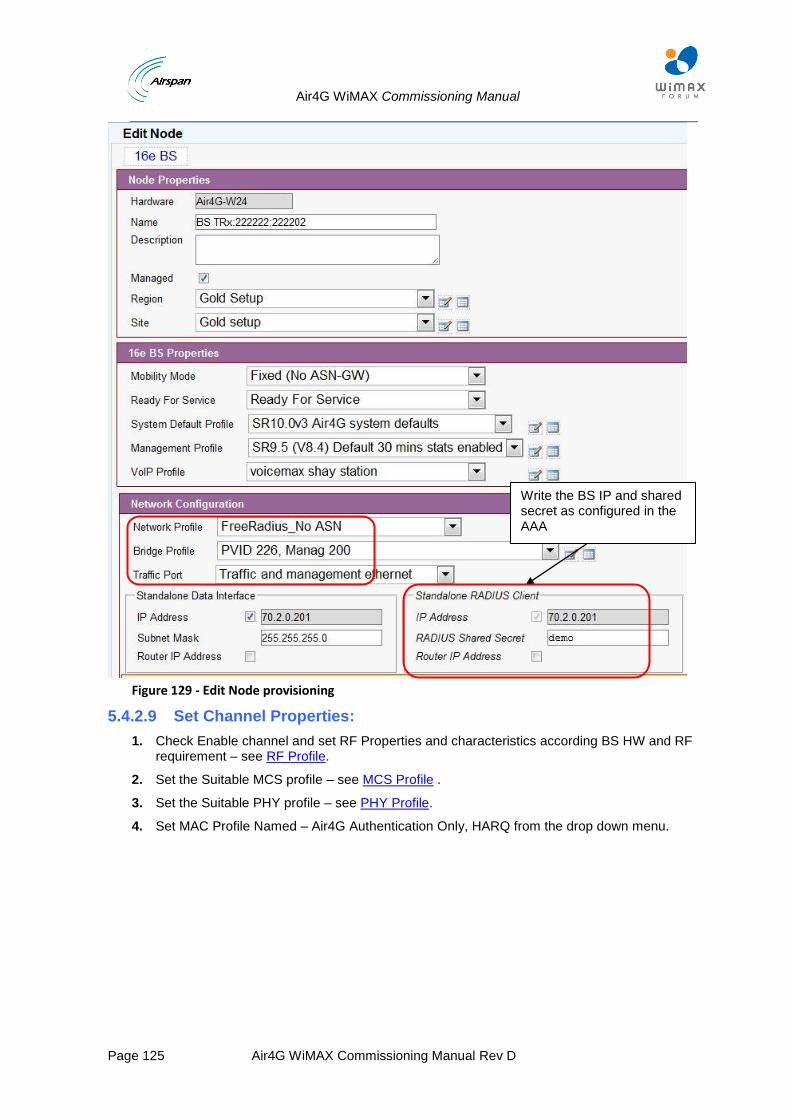
Air4G WiMAX Commissioning Manual
Page 125 Air4G WiMAX Commissioning Manual Rev D
Figure 129 - Edit Node provisioning
5.4.2.9 Set Channel Properties:
1. Check Enable channel and set RF Properties and characteristics according BS HW and RF requirement – see RF Profile.
2. Set the Suitable MCS profile – see MCS Profile .
3. Set the Suitable PHY profile – see PHY Profile.
4. Set MAC Profile Named – Air4G Authentication Only, HARQ from the drop down menu.
Write the BS IP and shared secret as configured in the AAA
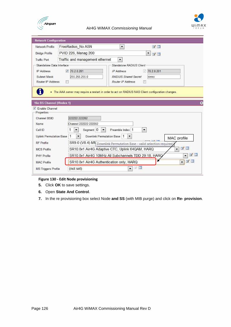
Air4G WiMAX Commissioning Manual
Page 126 Air4G WiMAX Commissioning Manual Rev D
Figure 130 - Edit Node provisioning
5. Click OK to save settings.
6. Open State And Control.
7. In the re provisioning box select Node and SS (with MIB purge) and click on Re- provision.
MAC profile
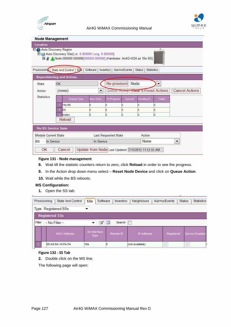
Air4G WiMAX Commissioning Manual
Page 127 Air4G WiMAX Commissioning Manual Rev D
Figure 131 - Node management
8. Wait till the statistic counters return to zero, click Reload in order to see the progress.
9. In the Action drop down menu select – Reset Node Device and click on Queue Action.
10. Wait while the BS reboots.
MS Configuration:
1. Open the SS tab:
Figure 132 - SS Tab
2. Double click on the MS line.
The following page will open:
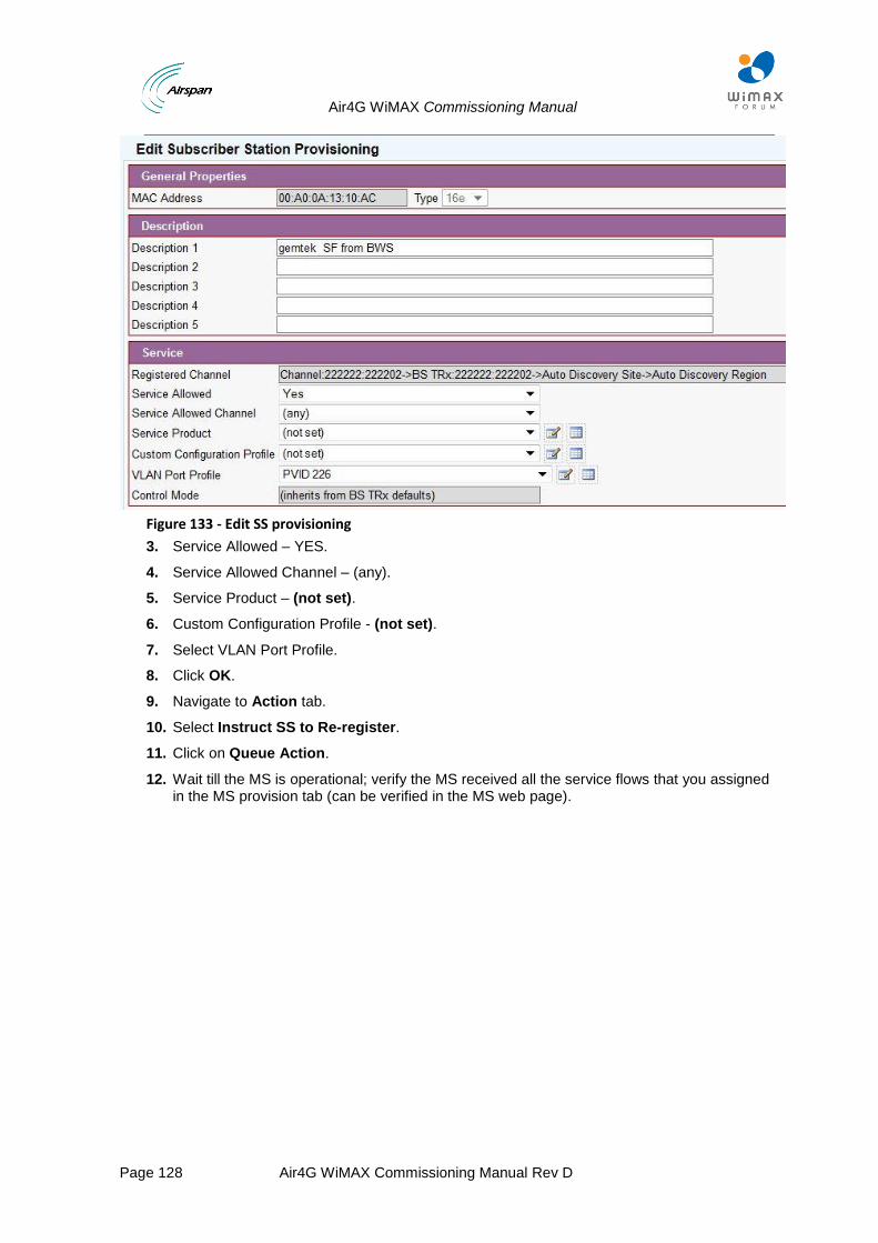
Air4G WiMAX Commissioning Manual
Page 128 Air4G WiMAX Commissioning Manual Rev D
Figure 133 - Edit SS provisioning
3. Service Allowed – YES.
4. Service Allowed Channel – (any).
5. Service Product – (not set).
6. Custom Configuration Profile - (not set).
7. Select VLAN Port Profile.
8. Click OK.
9. Navigate to Action tab.
10. Select Instruct SS to Re-register.
11. Click on Queue Action.
12. Wait till the MS is operational; verify the MS received all the service flows that you assigned in the MS provision tab (can be verified in the MS web page).
Air4G WiMAX Commissioning Manual
Page 129 Air4G WiMAX Commissioning Manual Rev D
5.5 Mobile WiMAX ASN-GW + AAA server
In this architecture the Air4G WiMAX BS is operating in the full mobile WiMAX network architecture. This architecture includes an ASN Gateway and AAA server and suited for fully mobile CPE subscribers.
The following applies in the full mobile WiMAX network architecture:
Data service flows between the BS and MSs are IP CS only.
All traffic between the MSs and the CSN network is routed through the ASNGW. Each data service flow between the BS and MSs is mapped to a GRE tunnel connection between the BS and the ASNGW.
Network entry process of the MS includes the ASNGW and AAA server for MS authentication.
AES Encryption of the data service flows in the WiMAX air interface between the BS and the MS using PKMv2 is applicable as the BS derives encryption keys from the AAA server.
The MSs are managed by the ASNGW and AAA server only, and not by Netspan. Data service flows to the MS are provisioned by the AAA and ASNGW.
Since all data service flows are IP CS, only L3 classifiers are applicable.
Mobile features of handover and idle mode are applicable (ASN-GW functionality).
5.5.1 Untagged Mode
BS Configuration:
1. Refer to sections 2-3 in order to discover the BS in Netspan.
2. Navigate to Configuration Management > select Node > Node.
3. Select the Configured BS and click Edit at the bottom of the page to enter Edit Mode.
4. Air Interface Type and Hardware are set automatically with 16e, Air4G WiMAX (Read only).
5. Select Mobility Mode - Mobile
6. Check - Managed.
7. Set Ready For Service - Ready For Service.
8. Set System Profile with a latest default Netspan Profile for Air4G.
9. Set Management Profile – as describe in section 5.
10. Set VoIP Profile - according to section 6 if no VoiceMAX is used, set this profile to not set.
11. Click List Button to open Node Network Profiles (16e) List, click Add located at the bottom of the list.
12. Create a new network profile as shown in the following example:
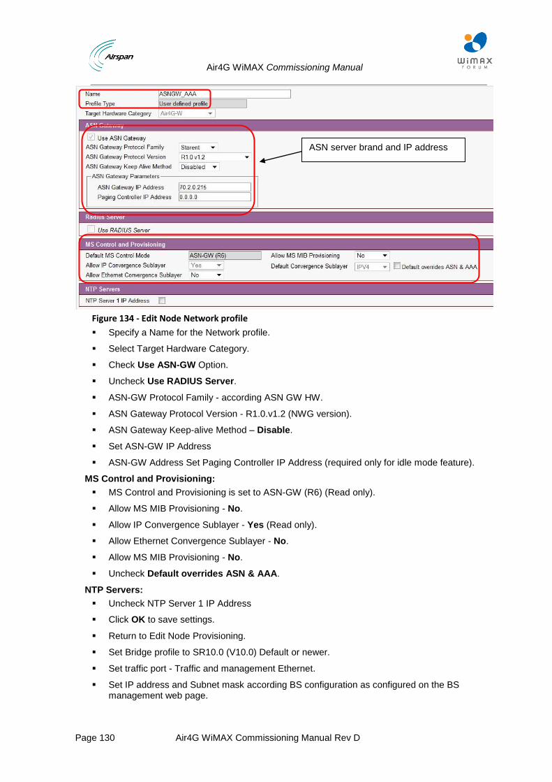
Air4G WiMAX Commissioning Manual
Page 130 Air4G WiMAX Commissioning Manual Rev D
Figure 134 - Edit Node Network profile
Specify a Name for the Network profile.
Select Target Hardware Category.
Check Use ASN-GW Option.
Uncheck Use RADIUS Server.
ASN-GW Protocol Family - according ASN GW HW.
ASN Gateway Protocol Version - R1.0.v1.2 (NWG version).
ASN Gateway Keep-alive Method – Disable.
Set ASN-GW IP Address
ASN-GW Address Set Paging Controller IP Address (required only for idle mode feature).
MS Control and Provisioning:
MS Control and Provisioning is set to ASN-GW (R6) (Read only).
Allow MS MIB Provisioning - No.
Allow IP Convergence Sublayer - Yes (Read only).
Allow Ethernet Convergence Sublayer - No.
Allow MS MIB Provisioning - No.
Uncheck Default overrides ASN & AAA.
NTP Servers:
Uncheck NTP Server 1 IP Address
Click OK to save settings.
Return to Edit Node Provisioning.
Set Bridge profile to SR10.0 (V10.0) Default or newer.
Set traffic port - Traffic and management Ethernet.
Set IP address and Subnet mask according BS configuration as configured on the BS management web page.
ASN server brand and IP address
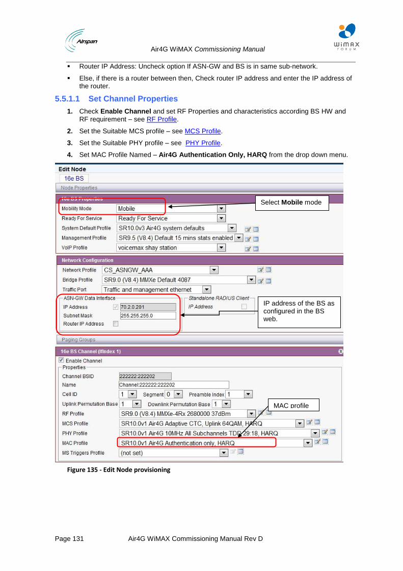
Air4G WiMAX Commissioning Manual
Page 131 Air4G WiMAX Commissioning Manual Rev D
Router IP Address: Uncheck option If ASN-GW and BS is in same sub-network.
Else, if there is a router between then, Check router IP address and enter the IP address of the router.
5.5.1.1 Set Channel Properties
1. Check Enable Channel and set RF Properties and characteristics according BS HW and RF requirement – see RF Profile.
2. Set the Suitable MCS profile – see MCS Profile.
3. Set the Suitable PHY profile – see PHY Profile.
4. Set MAC Profile Named – Air4G Authentication Only, HARQ from the drop down menu.
Figure 135 - Edit Node provisioning
MAC profile
Select Mobile mode
IP address of the BS as configured in the BS web.
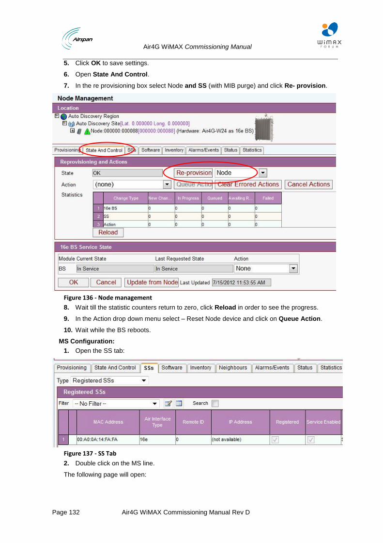
Air4G WiMAX Commissioning Manual
Page 132 Air4G WiMAX Commissioning Manual Rev D
5. Click OK to save settings.
6. Open State And Control.
7. In the re provisioning box select Node and SS (with MIB purge) and click Re- provision.
Figure 136 - Node management
8. Wait till the statistic counters return to zero, click Reload in order to see the progress.
9. In the Action drop down menu select – Reset Node device and click on Queue Action.
10. Wait while the BS reboots.
MS Configuration:
1. Open the SS tab:
Figure 137 - SS Tab
2. Double click on the MS line.
The following page will open:
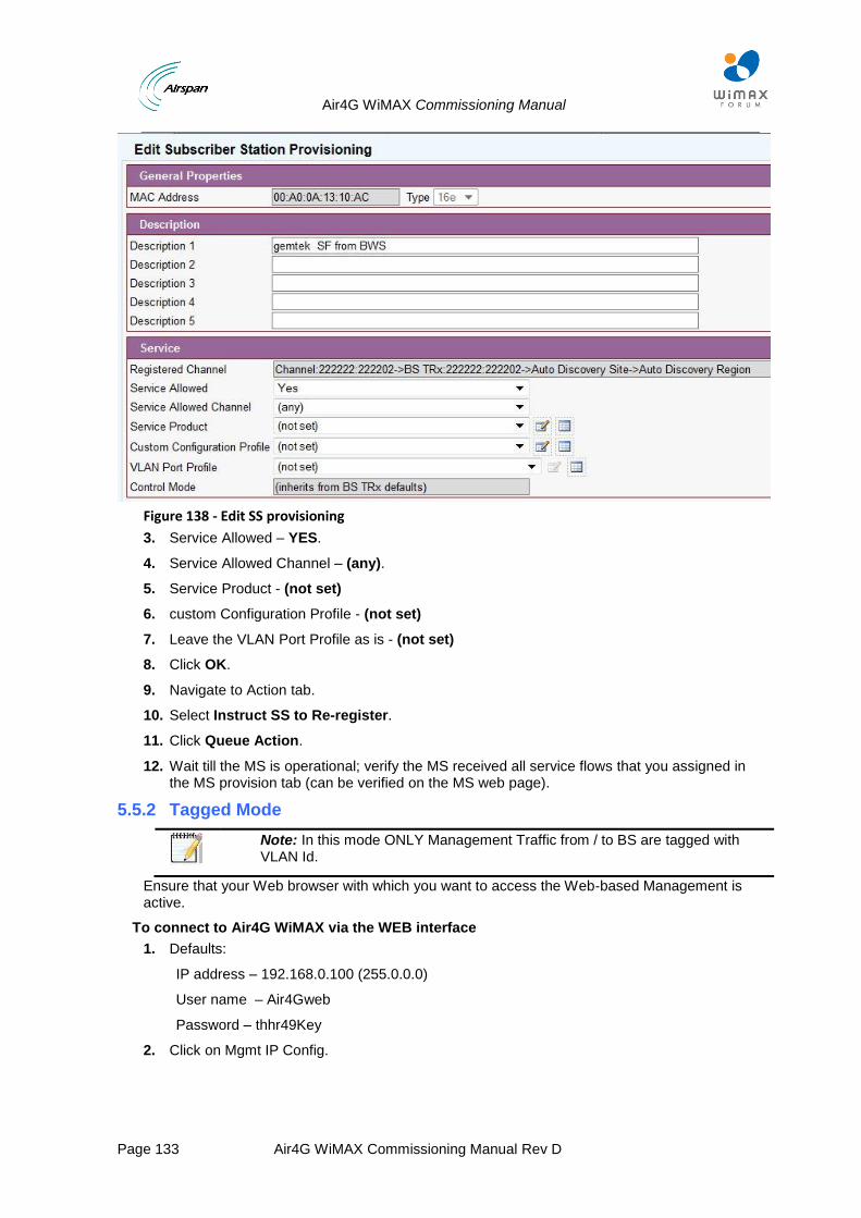
Air4G WiMAX Commissioning Manual
Page 133 Air4G WiMAX Commissioning Manual Rev D
Figure 138 - Edit SS provisioning
3. Service Allowed – YES.
4. Service Allowed Channel – (any).
5. Service Product - (not set)
6. custom Configuration Profile - (not set)
7. Leave the VLAN Port Profile as is - (not set)
8. Click OK.
9. Navigate to Action tab.
10. Select Instruct SS to Re-register.
11. Click Queue Action.
12. Wait till the MS is operational; verify the MS received all service flows that you assigned in the MS provision tab (can be verified on the MS web page).
5.5.2 Tagged Mode
Note: In this mode ONLY Management Traffic from / to BS are tagged with VLAN Id.
Ensure that your Web browser with which you want to access the Web-based Management is active.
To connect to Air4G WiMAX via the WEB interface
1. Defaults:
IP address – 192.168.0.100 (255.0.0.0)
User name – Air4Gweb
Password – thhr49Key
2. Click on Mgmt IP Config.
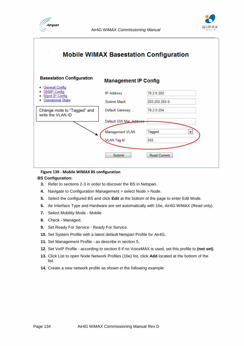
Air4G WiMAX Commissioning Manual
Page 134 Air4G WiMAX Commissioning Manual Rev D
Figure 139 - Mobile WiMAX BS configuration
BS Configuration:
3. Refer to sections 2-3 in order to discover the BS in Netspan.
4. Navigate to Configuration Management > select Node > Node.
5. Select the configured BS and click Edit at the bottom of the page to enter Edit Mode.
6. Air Interface Type and Hardware are set automatically with 16e, Air4G WiMAX (Read only).
7. Select Mobility Mode - Mobile
8. Check - Managed.
9. Set Ready For Service - Ready For Service.
10. Set System Profile with a latest default Netspan Profile for Air4G.
11. Set Management Profile - as describe in section 5.
12. Set VoIP Profile - according to section 6 if no VoiceMAX is used, set this profile to (not set).
13. Click List to open Node Network Profiles (16e) list, click Add located at the bottom of the list.
14. Create a new network profile as shown in the following example:
Change mote to “Tagged” and write the VLAN ID
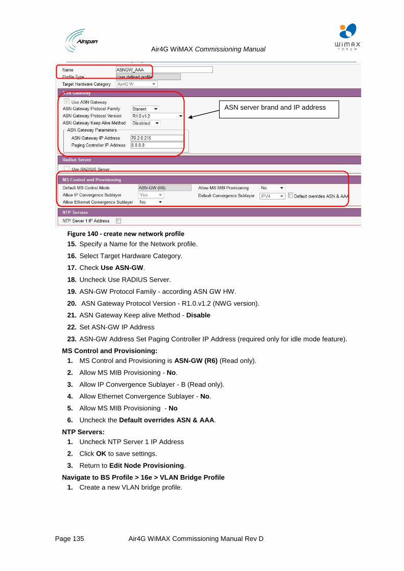
Air4G WiMAX Commissioning Manual
Page 135 Air4G WiMAX Commissioning Manual Rev D
Figure 140 - create new network profile
15. Specify a Name for the Network profile.
16. Select Target Hardware Category.
17. Check Use ASN-GW.
18. Uncheck Use RADIUS Server.
19. ASN-GW Protocol Family - according ASN GW HW.
20. ASN Gateway Protocol Version - R1.0.v1.2 (NWG version).
21. ASN Gateway Keep alive Method - Disable
22. Set ASN-GW IP Address
23. ASN-GW Address Set Paging Controller IP Address (required only for idle mode feature).
MS Control and Provisioning:
1. MS Control and Provisioning is ASN-GW (R6) (Read only).
2. Allow MS MIB Provisioning - No.
3. Allow IP Convergence Sublayer - B (Read only).
4. Allow Ethernet Convergence Sublayer - No.
5. Allow MS MIB Provisioning - No
6. Uncheck the Default overrides ASN & AAA.
NTP Servers:
1. Uncheck NTP Server 1 IP Address
2. Click OK to save settings.
3. Return to Edit Node Provisioning.
Navigate to BS Profile > 16e > VLAN Bridge Profile
1. Create a new VLAN bridge profile.
ASN server brand and IP address
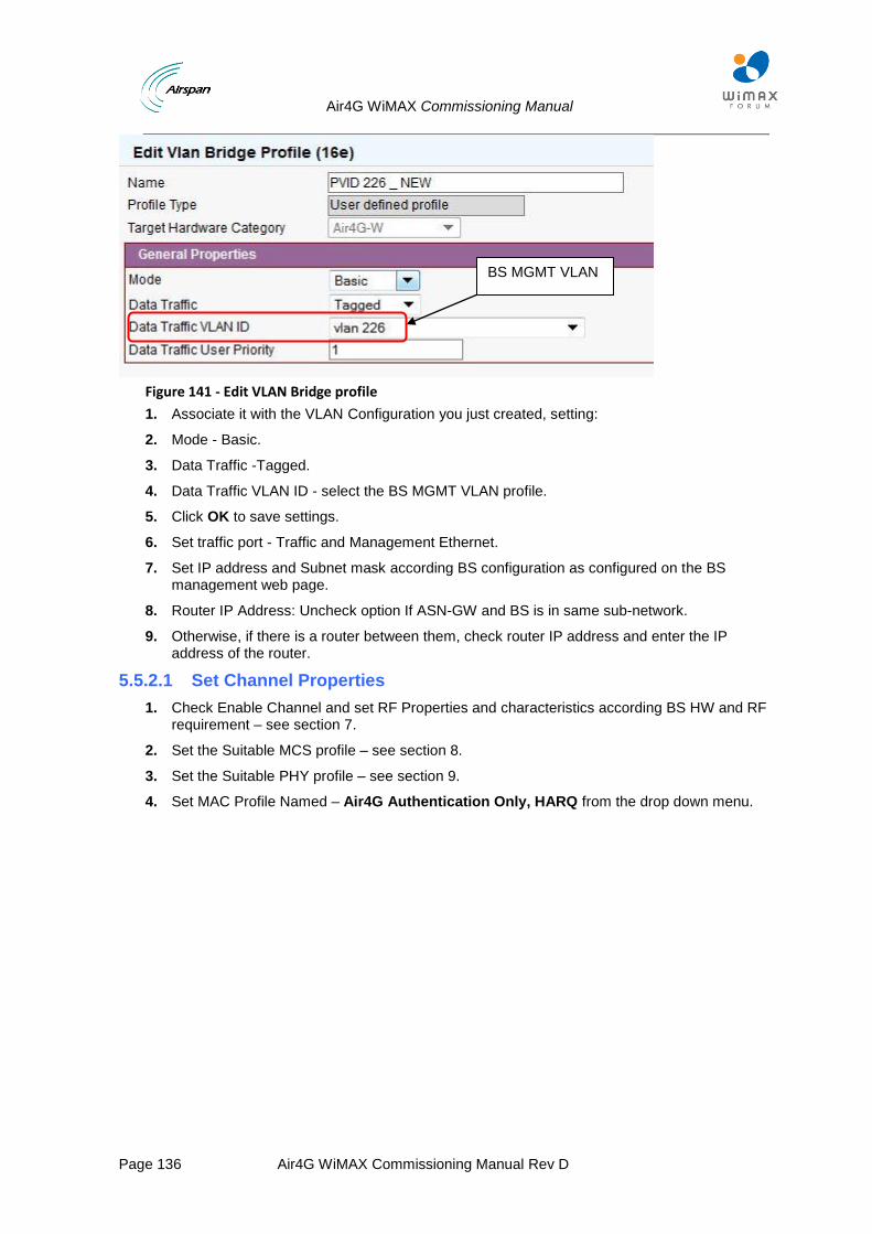
Air4G WiMAX Commissioning Manual
Page 136 Air4G WiMAX Commissioning Manual Rev D
Figure 141 - Edit VLAN Bridge profile
1. Associate it with the VLAN Configuration you just created, setting:
2. Mode - Basic.
3. Data Traffic -Tagged.
4. Data Traffic VLAN ID - select the BS MGMT VLAN profile.
5. Click OK to save settings.
6. Set traffic port - Traffic and Management Ethernet.
7. Set IP address and Subnet mask according BS configuration as configured on the BS management web page.
8. Router IP Address: Uncheck option If ASN-GW and BS is in same sub-network.
9. Otherwise, if there is a router between them, check router IP address and enter the IP address of the router.
5.5.2.1 Set Channel Properties
1. Check Enable Channel and set RF Properties and characteristics according BS HW and RF requirement – see section 7.
2. Set the Suitable MCS profile – see section 8.
3. Set the Suitable PHY profile – see section 9.
4. Set MAC Profile Named – Air4G Authentication Only, HARQ from the drop down menu.
BS MGMT VLAN
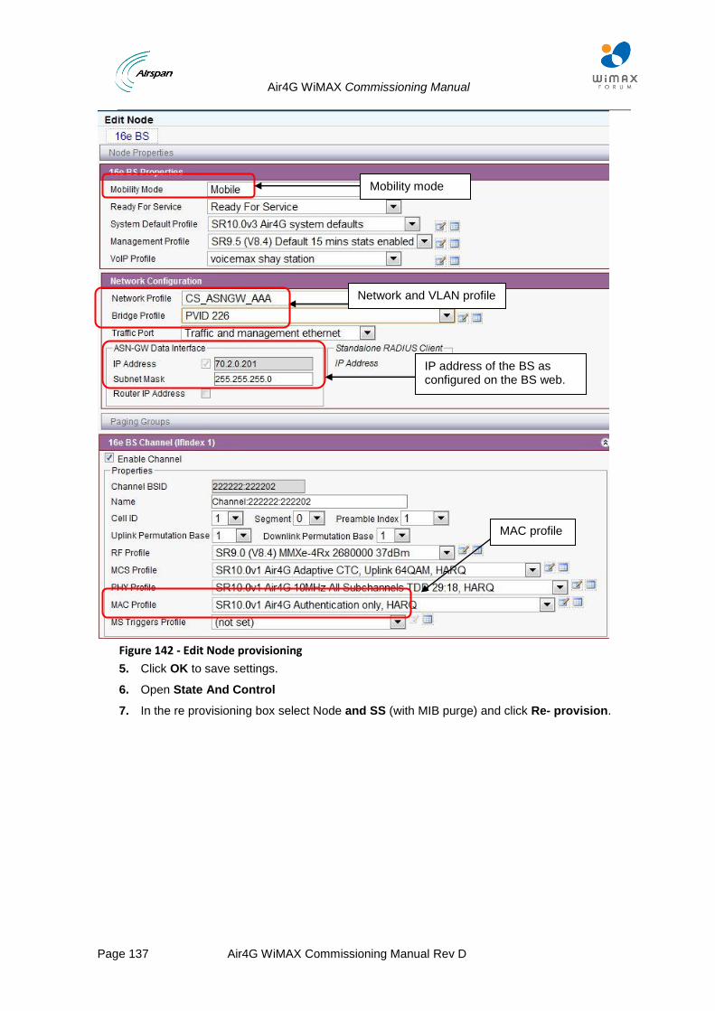
Air4G WiMAX Commissioning Manual
Page 137 Air4G WiMAX Commissioning Manual Rev D
Figure 142 - Edit Node provisioning
5. Click OK to save settings.
6. Open State And Control
7. In the re provisioning box select Node and SS (with MIB purge) and click Re- provision.
Mobility mode
Network and VLAN profile
IP address of the BS as configured on the BS web.
MAC profile
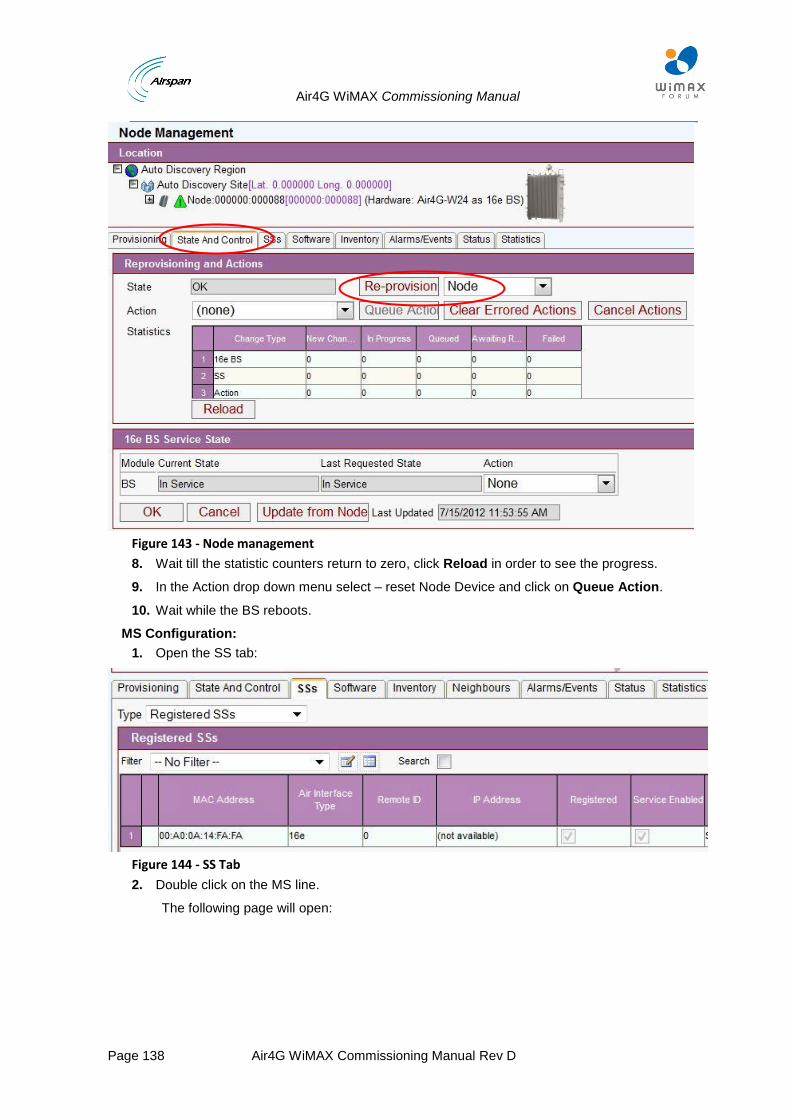
Air4G WiMAX Commissioning Manual
Page 138 Air4G WiMAX Commissioning Manual Rev D
Figure 143 - Node management
8. Wait till the statistic counters return to zero, click Reload in order to see the progress.
9. In the Action drop down menu select – reset Node Device and click on Queue Action.
10. Wait while the BS reboots.
MS Configuration:
1. Open the SS tab:
Figure 144 - SS Tab
2. Double click on the MS line.
The following page will open:
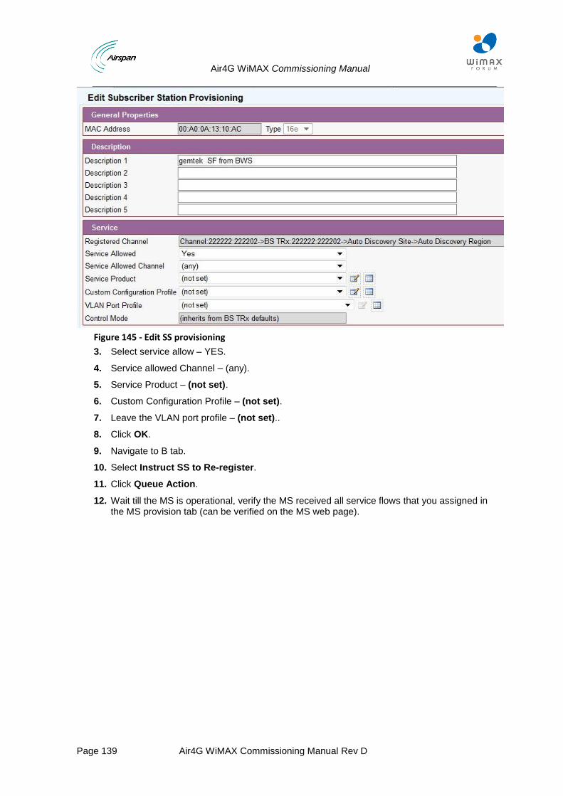
Air4G WiMAX Commissioning Manual
Page 139 Air4G WiMAX Commissioning Manual Rev D
Figure 145 - Edit SS provisioning
3. Select service allow – YES.
4. Service allowed Channel – (any).
5. Service Product – (not set).
6. Custom Configuration Profile – (not set).
7. Leave the VLAN port profile – (not set)..
8. Click OK.
9. Navigate to B tab.
10. Select Instruct SS to Re-register.
11. Click Queue Action.
12. Wait till the MS is operational, verify the MS received all service flows that you assigned in the MS provision tab (can be verified on the MS web page).
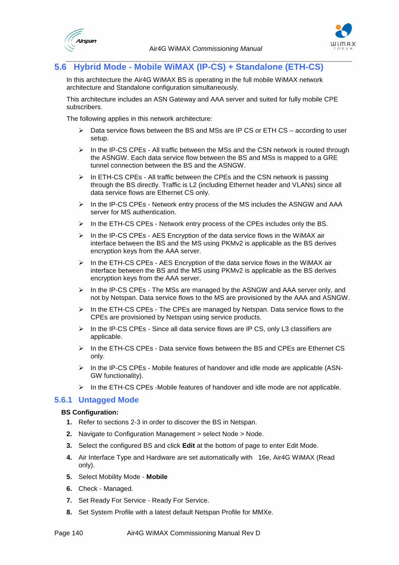
Air4G WiMAX Commissioning Manual
Page 140 Air4G WiMAX Commissioning Manual Rev D
5.6 Hybrid Mode - Mobile WiMAX (IP-CS) + Standalone (ETH-CS)
In this architecture the Air4G WiMAX BS is operating in the full mobile WiMAX network architecture and Standalone configuration simultaneously.
This architecture includes an ASN Gateway and AAA server and suited for fully mobile CPE subscribers.
The following applies in this network architecture:
Data service flows between the BS and MSs are IP CS or ETH CS – according to user setup.
In the IP-CS CPEs - All traffic between the MSs and the CSN network is routed through the ASNGW. Each data service flow between the BS and MSs is mapped to a GRE tunnel connection between the BS and the ASNGW.
In ETH-CS CPEs - All traffic between the CPEs and the CSN network is passing through the BS directly. Traffic is L2 (including Ethernet header and VLANs) since all data service flows are Ethernet CS only.
In the IP-CS CPEs - Network entry process of the MS includes the ASNGW and AAA server for MS authentication.
In the ETH-CS CPEs - Network entry process of the CPEs includes only the BS.
In the IP-CS CPEs - AES Encryption of the data service flows in the WiMAX air interface between the BS and the MS using PKMv2 is applicable as the BS derives encryption keys from the AAA server.
In the ETH-CS CPEs - AES Encryption of the data service flows in the WiMAX air interface between the BS and the MS using PKMv2 is applicable as the BS derives encryption keys from the AAA server.
In the IP-CS CPEs - The MSs are managed by the ASNGW and AAA server only, and not by Netspan. Data service flows to the MS are provisioned by the AAA and ASNGW.
In the ETH-CS CPEs - The CPEs are managed by Netspan. Data service flows to the CPEs are provisioned by Netspan using service products.
In the IP-CS CPEs - Since all data service flows are IP CS, only L3 classifiers are applicable.
In the ETH-CS CPEs - Data service flows between the BS and CPEs are Ethernet CS only.
In the IP-CS CPEs - Mobile features of handover and idle mode are applicable (ASN-GW functionality).
In the ETH-CS CPEs -Mobile features of handover and idle mode are not applicable.
5.6.1 Untagged Mode
BS Configuration:
1. Refer to sections 2-3 in order to discover the BS in Netspan.
2. Navigate to Configuration Management > select Node > Node.
3. Select the configured BS and click Edit at the bottom of page to enter Edit Mode.
4. Air Interface Type and Hardware are set automatically with 16e, Air4G WiMAX (Read only).
5. Select Mobility Mode - Mobile
6. Check - Managed.
7. Set Ready For Service - Ready For Service.
8. Set System Profile with a latest default Netspan Profile for MMXe.
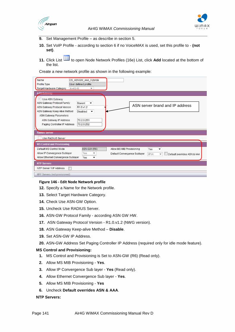
Air4G WiMAX Commissioning Manual
Page 141 Air4G WiMAX Commissioning Manual Rev D
9. Set Management Profile – as describe in section 5.
10. Set VoIP Profile - according to section 6 if no VoiceMAX is used, set this profile to - (not set).
11. Click List to open Node Network Profiles (16e) List, click Add located at the bottom of the list.
Create a new network profile as shown in the following example:
Figure 146 - Edit Node Network profile
12. Specify a Name for the Network profile.
13. Select Target Hardware Category.
14. Check Use ASN-GW Option.
15. Uncheck Use RADIUS Server.
16. ASN-GW Protocol Family - according ASN GW HW.
17. ASN Gateway Protocol Version - R1.0.v1.2 (NWG version).
18. ASN Gateway Keep-alive Method – Disable.
19. Set ASN-GW IP Address.
20. ASN-GW Address Set Paging Controller IP Address (required only for idle mode feature).
MS Control and Provisioning:
1. MS Control and Provisioning is Set to ASN-GW (R6) (Read only).
2. Allow MS MIB Provisioning - Yes.
3. Allow IP Convergence Sub layer - Yes (Read only).
4. Allow Ethernet Convergence Sub layer - Yes.
5. Allow MS MIB Provisioning - Yes
6. Uncheck Default overrides ASN & AAA.
NTP Servers:
ASN server brand and IP address
Air4G WiMAX Commissioning Manual
Page 142 Air4G WiMAX Commissioning Manual Rev D
1. Uncheck NTP Server 1 IP Address
2. Click OK to save settings.
3. Return to Edit Node Provisioning.
4. Set Network profile that was created in the previous section.
5. Set Bridge profile to SR9.0 (V8.4) MMXe default or newer.
6. Set Traffic Port - Traffic and Management Ethernet.
7. Set IP address and Subnet mask according BS configuration as configured on the BS management web page.
8. Router IP Address: Uncheck option If ASN-GW and BS is in same sub-network.
9. Otherwise, if there is a router between them check the router IP address and enter the IP address of the router.
5.6.1.1 Set Channel Properties
1. Check Enable Channel and set RF Properties and characterizes according BS HW and RF requirement – see RF Profile.
2. Set the Suitable MCS profile – see MCS Profile.
3. Set the Suitable PHY profile – see PHY Profile.
4. Set MAC Profile Named – Air4G Authentication Only, HARQ from the drop down menu.
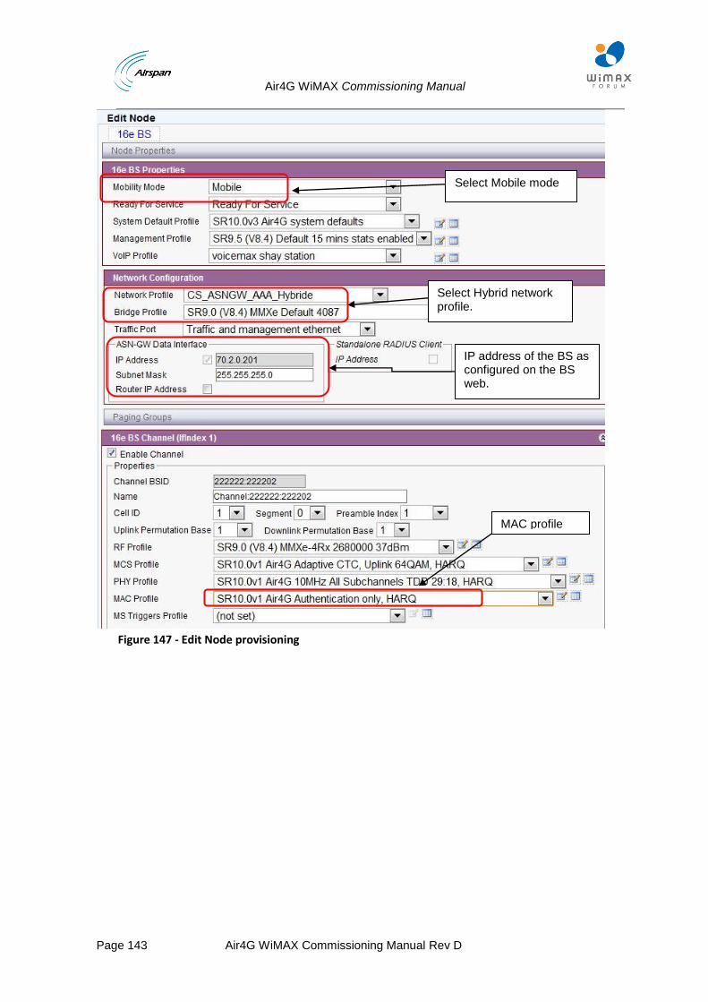
Air4G WiMAX Commissioning Manual
Page 143 Air4G WiMAX Commissioning Manual Rev D
Figure 147 - Edit Node provisioning
MAC profile
Select Mobile mode
IP address of the BS as configured on the BS web.
Select Hybrid network profile.
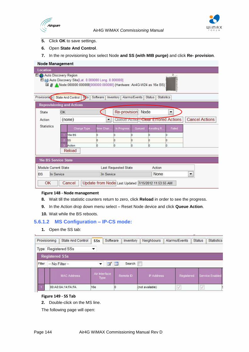
Air4G WiMAX Commissioning Manual
Page 144 Air4G WiMAX Commissioning Manual Rev D
5. Click OK to save settings.
6. Open State And Control.
7. In the re provisioning box select Node and SS (with MIB purge) and click Re- provision.
Figure 148 - Node management
8. Wait till the statistic counters return to zero, click Reload in order to see the progress.
9. In the Action drop down menu select – Reset Node device and click Queue Action.
10. Wait while the BS reboots.
5.6.1.2 MS Configuration – IP-CS mode:
1. Open the SS tab:
Figure 149 - SS Tab
2. Double-click on the MS line.
The following page will open:
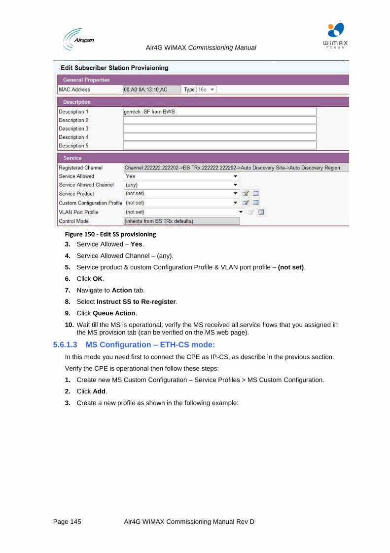
Air4G WiMAX Commissioning Manual
Page 145 Air4G WiMAX Commissioning Manual Rev D
Figure 150 - Edit SS provisioning
3. Service Allowed – Yes.
4. Service Allowed Channel – (any).
5. Service product & custom Configuration Profile & VLAN port profile – (not set).
6. Click OK.
7. Navigate to Action tab.
8. Select Instruct SS to Re-register.
9. Click Queue Action.
10. Wait till the MS is operational; verify the MS received all service flows that you assigned in the MS provision tab (can be verified on the MS web page).
5.6.1.3 MS Configuration – ETH-CS mode:
In this mode you need first to connect the CPE as IP-CS, as describe in the previous section.
Verify the CPE is operational then follow these steps:
1. Create new MS Custom Configuration – Service Profiles > MS Custom Configuration.
2. Click Add.
3. Create a new profile as shown in the following example:
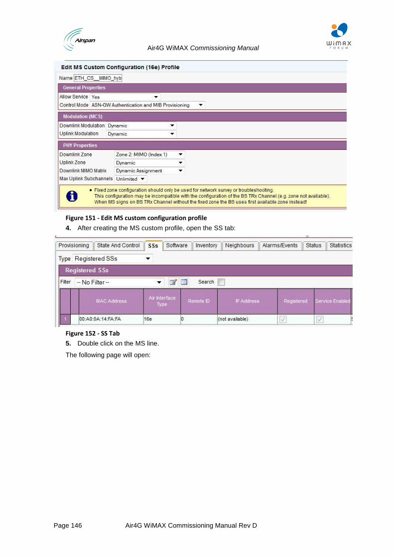
Air4G WiMAX Commissioning Manual
Page 146 Air4G WiMAX Commissioning Manual Rev D
Figure 151 - Edit MS custom configuration profile
4. After creating the MS custom profile, open the SS tab:
Figure 152 - SS Tab
5. Double click on the MS line.
The following page will open:
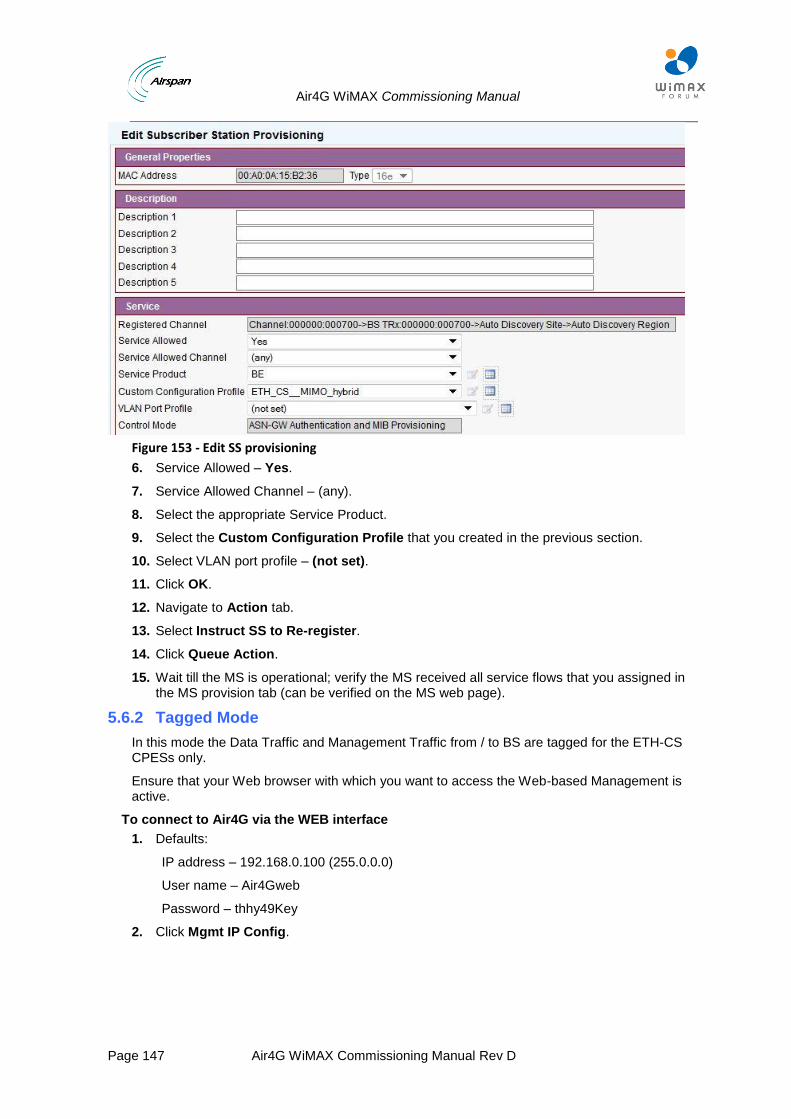
Air4G WiMAX Commissioning Manual
Page 147 Air4G WiMAX Commissioning Manual Rev D
Figure 153 - Edit SS provisioning
6. Service Allowed – Yes.
7. Service Allowed Channel – (any).
8. Select the appropriate Service Product.
9. Select the Custom Configuration Profile that you created in the previous section.
10. Select VLAN port profile – (not set).
11. Click OK.
12. Navigate to Action tab.
13. Select Instruct SS to Re-register.
14. Click Queue Action.
15. Wait till the MS is operational; verify the MS received all service flows that you assigned in the MS provision tab (can be verified on the MS web page).
5.6.2 Tagged Mode
In this mode the Data Traffic and Management Traffic from / to BS are tagged for the ETH-CS CPESs only.
Ensure that your Web browser with which you want to access the Web-based Management is active.
To connect to Air4G via the WEB interface
1. Defaults:
IP address – 192.168.0.100 (255.0.0.0)
User name – Air4Gweb
Password – thhy49Key
2. Click Mgmt IP Config.
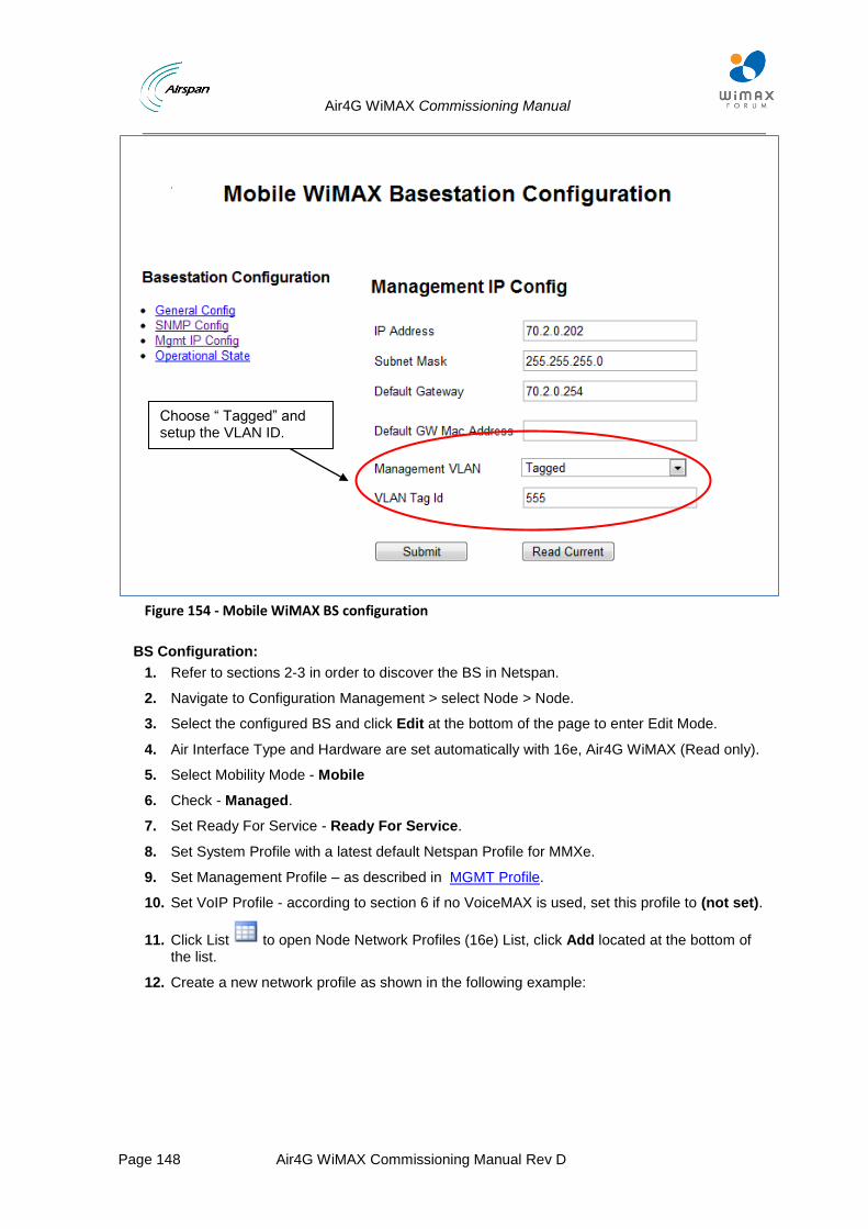
Air4G WiMAX Commissioning Manual
Page 148 Air4G WiMAX Commissioning Manual Rev D
Figure 154 - Mobile WiMAX BS configuration
BS Configuration:
1. Refer to sections 2-3 in order to discover the BS in Netspan.
2. Navigate to Configuration Management > select Node > Node.
3. Select the configured BS and click Edit at the bottom of the page to enter Edit Mode.
4. Air Interface Type and Hardware are set automatically with 16e, Air4G WiMAX (Read only).
5. Select Mobility Mode - Mobile
6. Check - Managed.
7. Set Ready For Service - Ready For Service.
8. Set System Profile with a latest default Netspan Profile for MMXe.
9. Set Management Profile – as described in MGMT Profile.
10. Set VoIP Profile - according to section 6 if no VoiceMAX is used, set this profile to (not set).
11. Click List to open Node Network Profiles (16e) List, click Add located at the bottom of the list.
12. Create a new network profile as shown in the following example:
Choose “ Tagged” and setup the VLAN ID.
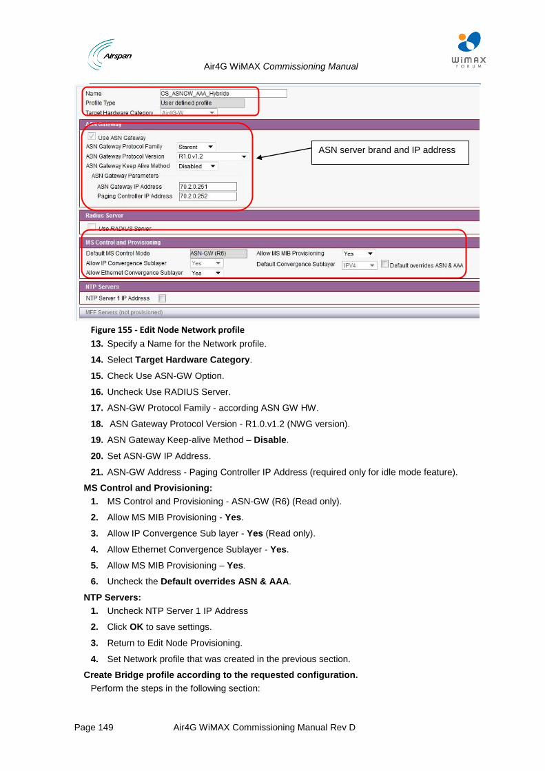
Air4G WiMAX Commissioning Manual
Page 149 Air4G WiMAX Commissioning Manual Rev D
Figure 155 - Edit Node Network profile
13. Specify a Name for the Network profile.
14. Select Target Hardware Category.
15. Check Use ASN-GW Option.
16. Uncheck Use RADIUS Server.
17. ASN-GW Protocol Family - according ASN GW HW.
18. ASN Gateway Protocol Version - R1.0.v1.2 (NWG version).
19. ASN Gateway Keep-alive Method – Disable.
20. Set ASN-GW IP Address.
21. ASN-GW Address - Paging Controller IP Address (required only for idle mode feature).
MS Control and Provisioning:
1. MS Control and Provisioning - ASN-GW (R6) (Read only).
2. Allow MS MIB Provisioning - Yes.
3. Allow IP Convergence Sub layer - Yes (Read only).
4. Allow Ethernet Convergence Sublayer - Yes.
5. Allow MS MIB Provisioning – Yes.
6. Uncheck the Default overrides ASN & AAA.
NTP Servers:
1. Uncheck NTP Server 1 IP Address
2. Click OK to save settings.
3. Return to Edit Node Provisioning.
4. Set Network profile that was created in the previous section.
Create Bridge profile according to the requested configuration.
Perform the steps in the following section:
ASN server brand and IP address
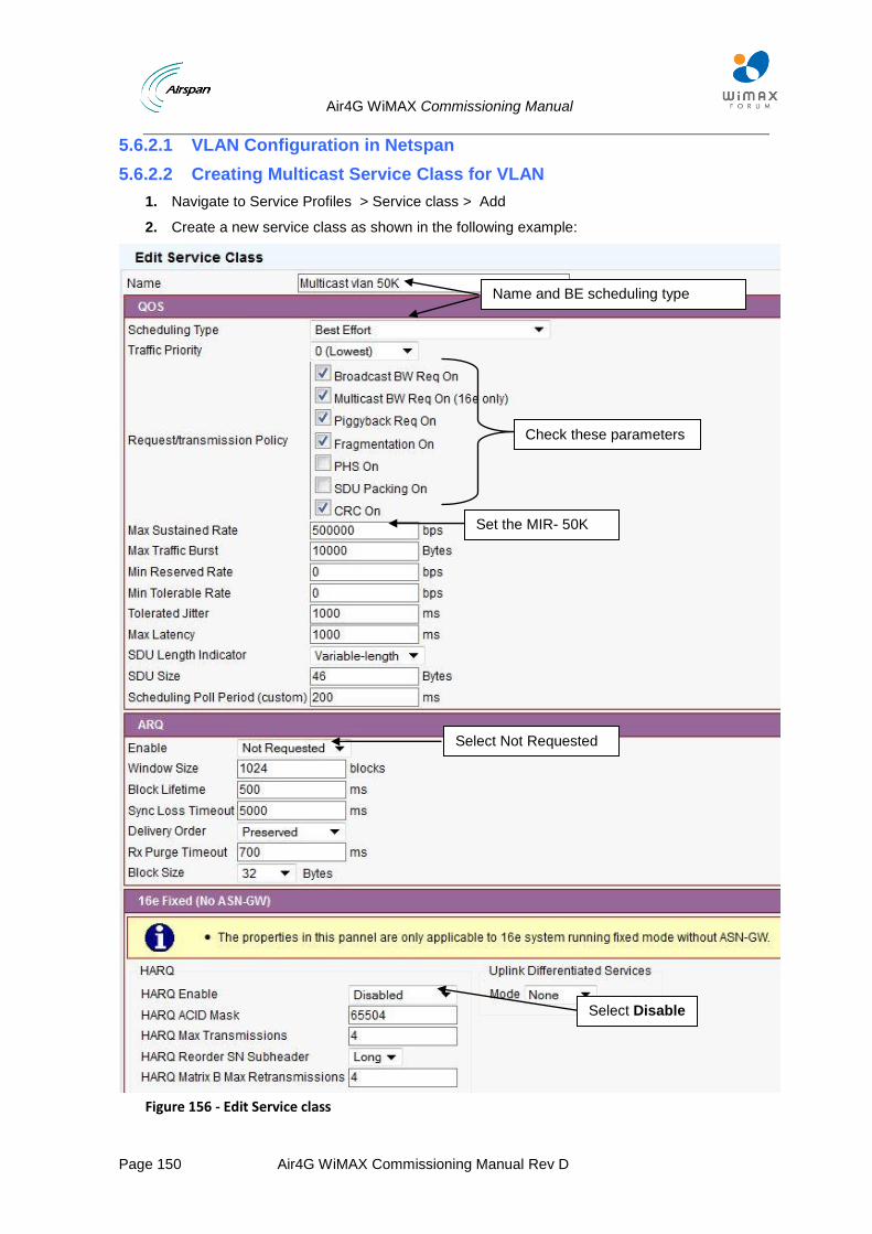
Air4G WiMAX Commissioning Manual
Page 150 Air4G WiMAX Commissioning Manual Rev D
5.6.2.1 VLAN Configuration in Netspan
5.6.2.2 Creating Multicast Service Class for VLAN
1. Navigate to Service Profiles > Service class > Add
2. Create a new service class as shown in the following example:
Figure 156 - Edit Service class
Name and BE scheduling type
Set the MIR- 50K
Select Disable
Select Not Requested
Check these parameters
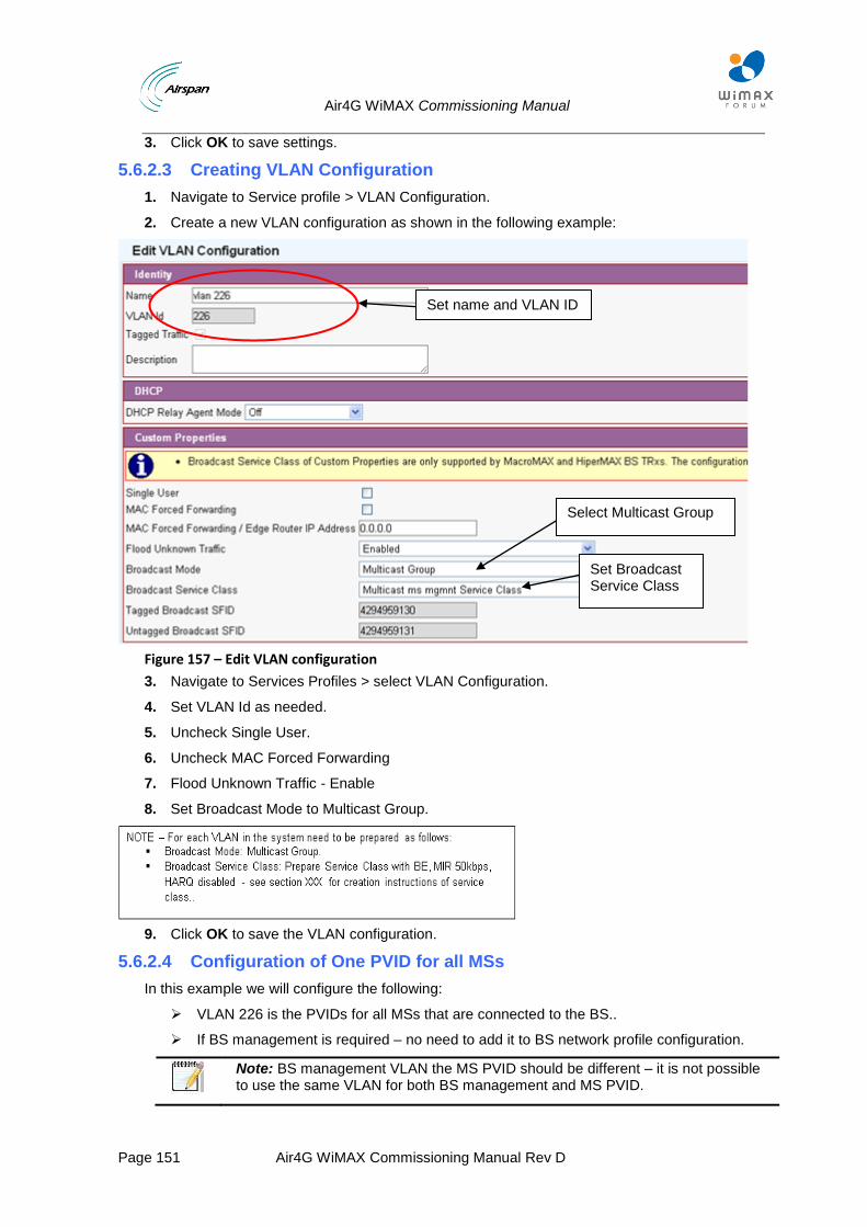
Air4G WiMAX Commissioning Manual
Page 151 Air4G WiMAX Commissioning Manual Rev D
3. Click OK to save settings.
5.6.2.3 Creating VLAN Configuration
1. Navigate to Service profile > VLAN Configuration.
2. Create a new VLAN configuration as shown in the following example:
Figure 157 – Edit VLAN configuration
3. Navigate to Services Profiles > select VLAN Configuration.
4. Set VLAN Id as needed.
5. Uncheck Single User.
6. Uncheck MAC Forced Forwarding
7. Flood Unknown Traffic - Enable
8. Set Broadcast Mode to Multicast Group.
9. Click OK to save the VLAN configuration.
5.6.2.4 Configuration of One PVID for all MSs
In this example we will configure the following:
VLAN 226 is the PVIDs for all MSs that are connected to the BS..
If BS management is required – no need to add it to BS network profile configuration.
Note: BS management VLAN the MS PVID should be different – it is not possible to use the same VLAN for both BS management and MS PVID.
Set name and VLAN ID
Select Multicast Group
Set Broadcast Service Class
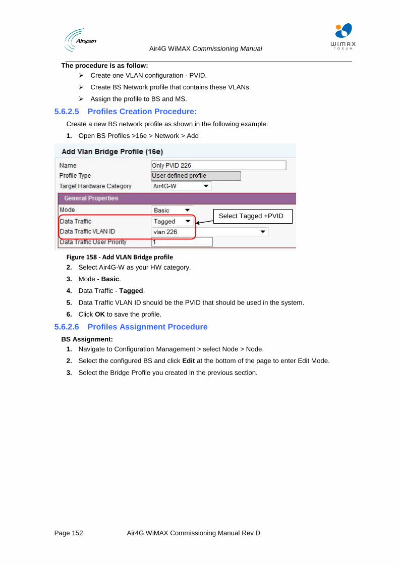
Air4G WiMAX Commissioning Manual
Page 152 Air4G WiMAX Commissioning Manual Rev D
The procedure is as follow:
Create one VLAN configuration - PVID.
Create BS Network profile that contains these VLANs.
Assign the profile to BS and MS.
5.6.2.5 Profiles Creation Procedure:
Create a new BS network profile as shown in the following example:
1. Open BS Profiles >16e > Network > Add
Figure 158 - Add VLAN Bridge profile
2. Select Air4G-W as your HW category.
3. Mode - Basic.
4. Data Traffic - Tagged.
5. Data Traffic VLAN ID should be the PVID that should be used in the system.
6. Click OK to save the profile.
5.6.2.6 Profiles Assignment Procedure
BS Assignment:
1. Navigate to Configuration Management > select Node > Node.
2. Select the configured BS and click Edit at the bottom of the page to enter Edit Mode.
3. Select the Bridge Profile you created in the previous section.
Select Tagged +PVID
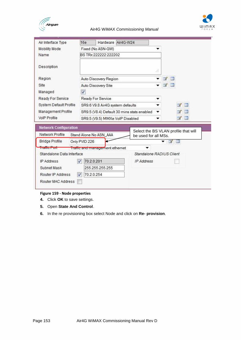
Air4G WiMAX Commissioning Manual
Page 153 Air4G WiMAX Commissioning Manual Rev D
Figure 159 - Node properties
4. Click OK to save settings.
5. Open State And Control.
6. In the re provisioning box select Node and click on Re- provision.
Select the BS VLAN profile that will be used for all MSs.
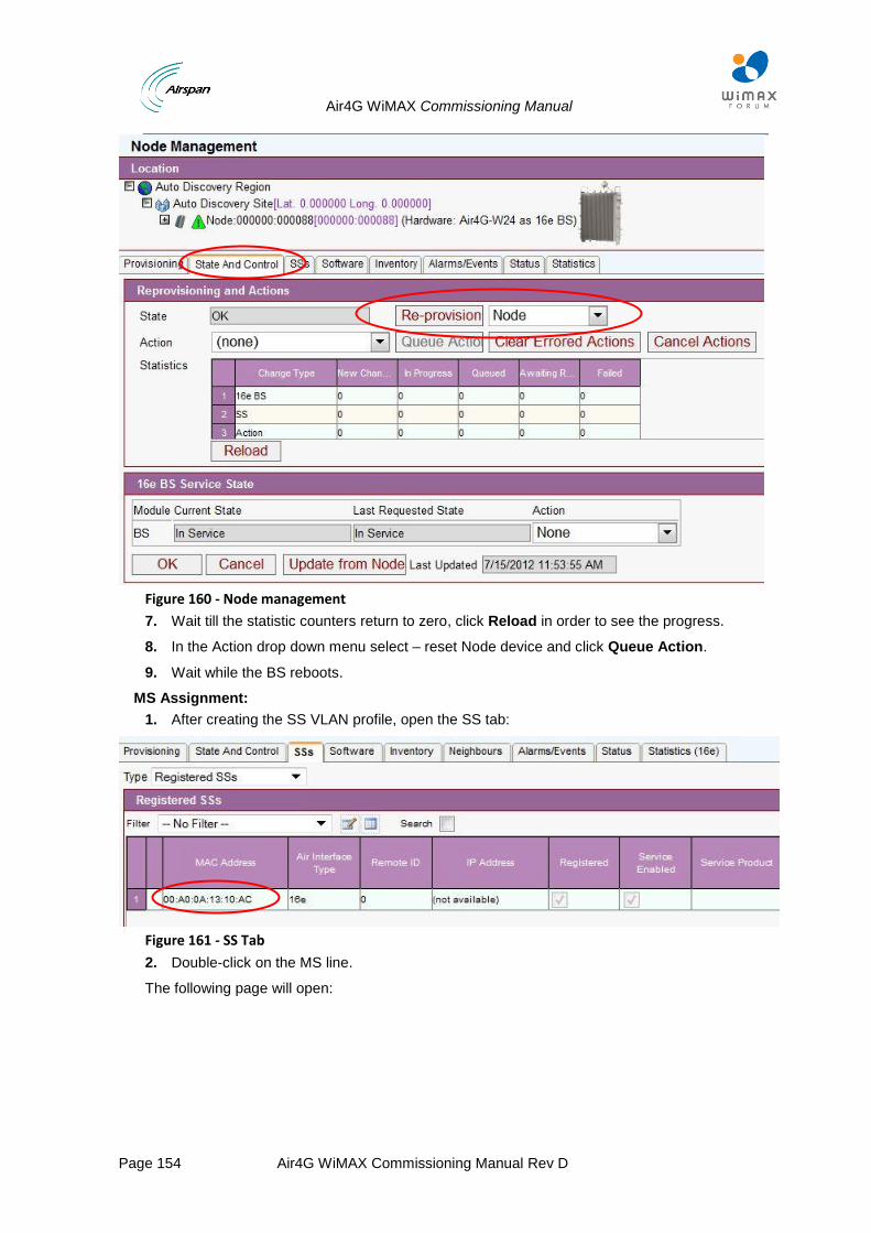
Air4G WiMAX Commissioning Manual
Page 154 Air4G WiMAX Commissioning Manual Rev D
Figure 160 - Node management
7. Wait till the statistic counters return to zero, click Reload in order to see the progress.
8. In the Action drop down menu select – reset Node device and click Queue Action.
9. Wait while the BS reboots.
MS Assignment:
1. After creating the SS VLAN profile, open the SS tab:
Figure 161 - SS Tab
2. Double-click on the MS line.
The following page will open:
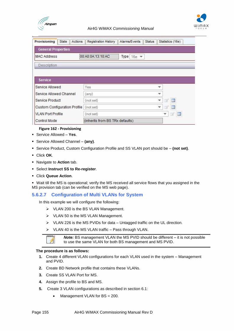
Air4G WiMAX Commissioning Manual
Page 155 Air4G WiMAX Commissioning Manual Rev D
Figure 162 - Provisioning
Service Allowed – Yes.
Service Allowed Channel – (any).
Service Product, Custom Configuration Profile and SS VLAN port should be – (not set).
Click OK.
Navigate to Action tab.
Select Instruct SS to Re-register.
Click Queue Action.
Wait till the MS is operational; verify the MS received all service flows that you assigned in the MS provision tab (can be verified on the MS web page).
5.6.2.7 Configuration of Multi VLANs for System
In this example we will configure the following:
VLAN 200 is the BS VLAN Management.
VLAN 50 is the MS VLAN Management.
VLAN 226 is the MS PVIDs for data – Untagged traffic on the UL direction.
VLAN 40 is the MS VLAN traffic – Pass through VLAN.
Note: BS management VLAN the MS PVID should be different – it is not possible to use the same VLAN for both BS management and MS PVID.
The procedure is as follows:
1. Create 4 different VLAN configurations for each VLAN used in the system – Management and PVID.
2. Create BD Network profile that contains these VLANs.
3. Create SS VLAN Port for MS.
4. Assign the profile to BS and MS.
5. Create 3 VLAN configurations as described in section 6.1:
Management VLAN for BS = 200.
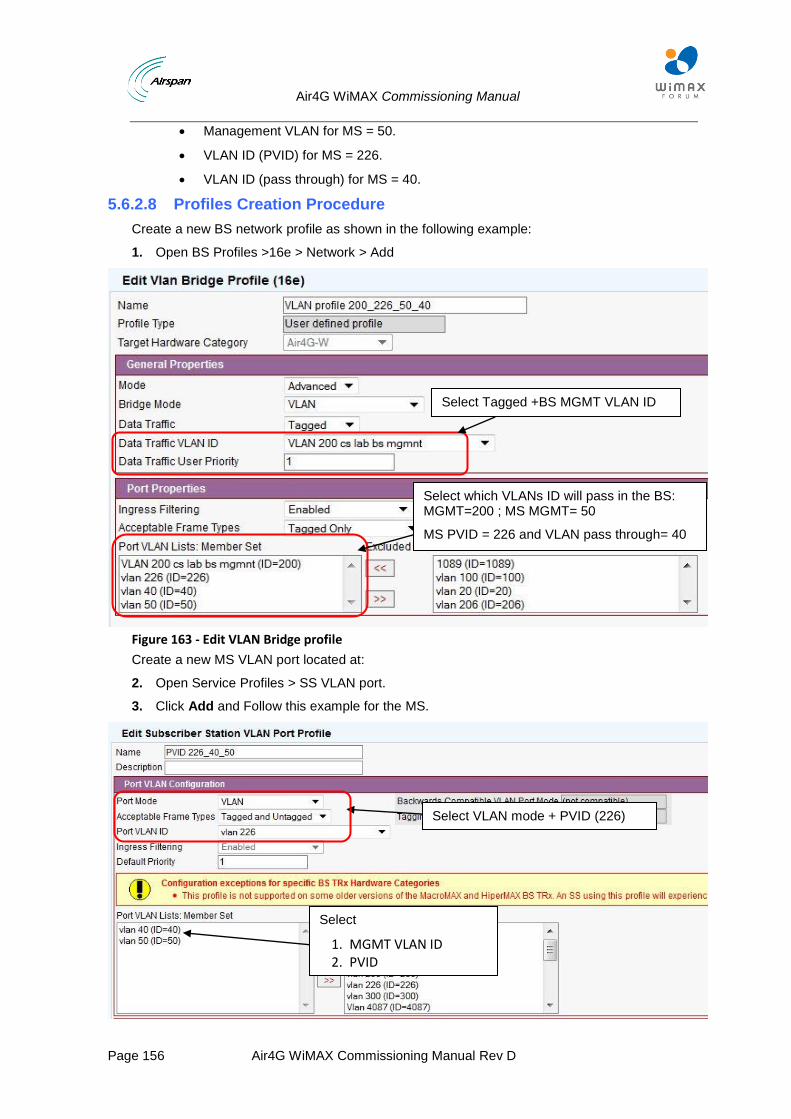
Air4G WiMAX Commissioning Manual
Page 156 Air4G WiMAX Commissioning Manual Rev D
Management VLAN for MS = 50.
VLAN ID (PVID) for MS = 226.
VLAN ID (pass through) for MS = 40.
5.6.2.8 Profiles Creation Procedure
Create a new BS network profile as shown in the following example:
1. Open BS Profiles >16e > Network > Add
Figure 163 - Edit VLAN Bridge profile
Create a new MS VLAN port located at:
2. Open Service Profiles > SS VLAN port.
3. Click Add and Follow this example for the MS.
Select Tagged +BS MGMT VLAN ID
Select which VLANs ID will pass in the BS: MGMT=200 ; MS MGMT= 50
MS PVID = 226 and VLAN pass through= 40
Select VLAN mode + PVID (226)
Select
1. MGMT VLAN ID 2. PVID
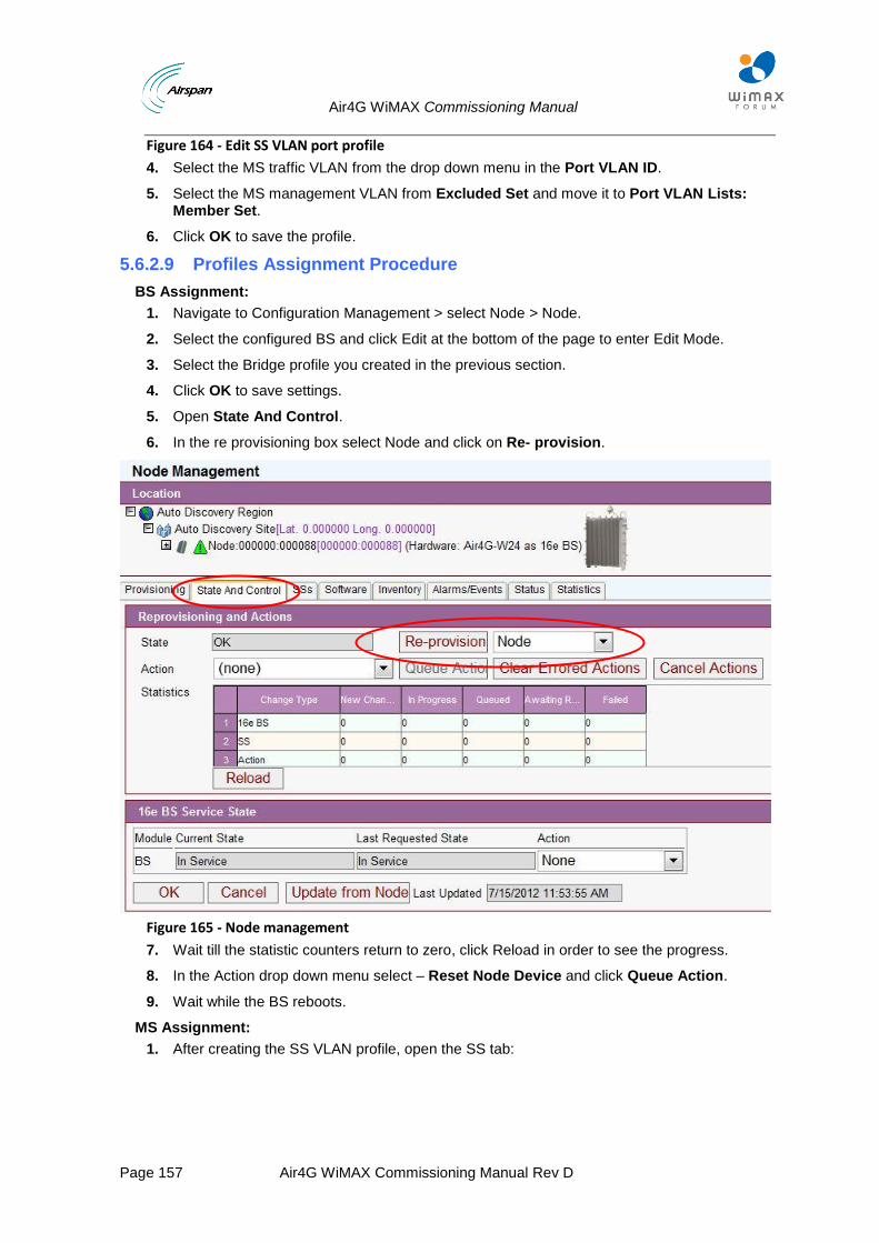
Air4G WiMAX Commissioning Manual
Page 157 Air4G WiMAX Commissioning Manual Rev D
Figure 164 - Edit SS VLAN port profile
4. Select the MS traffic VLAN from the drop down menu in the Port VLAN ID.
5. Select the MS management VLAN from Excluded Set and move it to Port VLAN Lists: Member Set.
6. Click OK to save the profile.
5.6.2.9 Profiles Assignment Procedure
BS Assignment:
1. Navigate to Configuration Management > select Node > Node.
2. Select the configured BS and click Edit at the bottom of the page to enter Edit Mode.
3. Select the Bridge profile you created in the previous section.
4. Click OK to save settings.
5. Open State And Control.
6. In the re provisioning box select Node and click on Re- provision.
Figure 165 - Node management
7. Wait till the statistic counters return to zero, click Reload in order to see the progress.
8. In the Action drop down menu select – Reset Node Device and click Queue Action.
9. Wait while the BS reboots.
MS Assignment:
1. After creating the SS VLAN profile, open the SS tab:
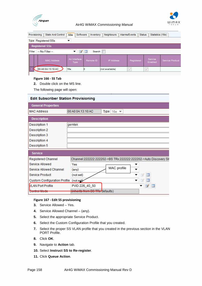
Air4G WiMAX Commissioning Manual
Page 158 Air4G WiMAX Commissioning Manual Rev D
Figure 166 - SS Tab
2. Double click on the MS line.
The following page will open:
Figure 167 - Edit SS provisioning
3. Service Allowed – Yes.
4. Service Allowed Channel – (any).
5. Select the appropriate Service Product.
6. Select the Custom Configuration Profile that you created.
7. Select the proper SS VLAN profile that you created in the previous section in the VLAN PORT Profile.
8. Click OK.
9. Navigate to Action tab.
10. Select Instruct SS to Re-register.
11. Click Queue Action.
MAC profile
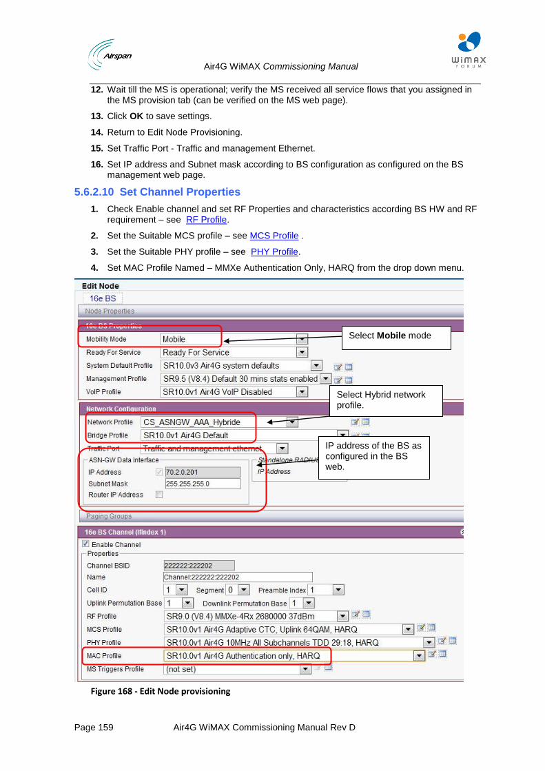
Air4G WiMAX Commissioning Manual
Page 159 Air4G WiMAX Commissioning Manual Rev D
12. Wait till the MS is operational; verify the MS received all service flows that you assigned in the MS provision tab (can be verified on the MS web page).
13. Click OK to save settings.
14. Return to Edit Node Provisioning.
15. Set Traffic Port - Traffic and management Ethernet.
16. Set IP address and Subnet mask according to BS configuration as configured on the BS management web page.
5.6.2.10 Set Channel Properties
1. Check Enable channel and set RF Properties and characteristics according BS HW and RF requirement – see RF Profile.
2. Set the Suitable MCS profile – see MCS Profile .
3. Set the Suitable PHY profile – see PHY Profile.
4. Set MAC Profile Named – MMXe Authentication Only, HARQ from the drop down menu.
Figure 168 - Edit Node provisioning
Select Mobile mode
IP address of the BS as configured in the BS web.
Select Hybrid network profile.
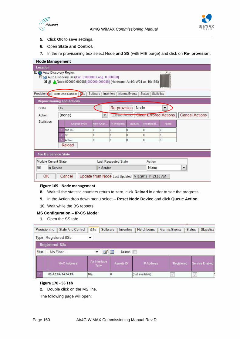
Air4G WiMAX Commissioning Manual
Page 160 Air4G WiMAX Commissioning Manual Rev D
5. Click OK to save settings.
6. Open State and Control.
7. In the re provisioning box select Node and SS (with MIB purge) and click on Re- provision.
Figure 169 - Node management
8. Wait till the statistic counters return to zero, click Reload in order to see the progress.
9. In the Action drop down menu select – Reset Node Device and click Queue Action.
10. Wait while the BS reboots.
MS Configuration – IP-CS Mode:
1. Open the SS tab:
Figure 170 - SS Tab
2. Double click on the MS line.
The following page will open:
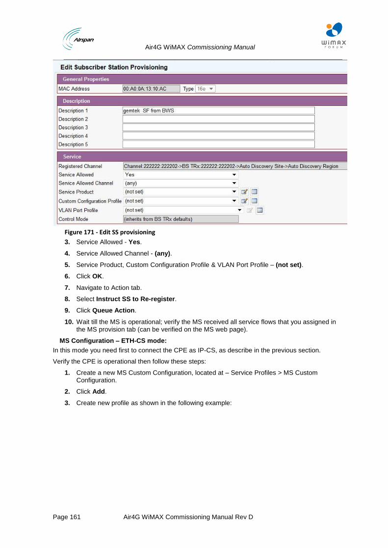
Air4G WiMAX Commissioning Manual
Page 161 Air4G WiMAX Commissioning Manual Rev D
Figure 171 - Edit SS provisioning
3. Service Allowed - Yes.
4. Service Allowed Channel - (any).
5. Service Product, Custom Configuration Profile & VLAN Port Profile – (not set).
6. Click OK.
7. Navigate to Action tab.
8. Select Instruct SS to Re-register.
9. Click Queue Action.
10. Wait till the MS is operational; verify the MS received all service flows that you assigned in the MS provision tab (can be verified on the MS web page).
MS Configuration – ETH-CS mode:
In this mode you need first to connect the CPE as IP-CS, as describe in the previous section.
Verify the CPE is operational then follow these steps:
1. Create a new MS Custom Configuration, located at – Service Profiles > MS Custom Configuration.
2. Click Add.
3. Create new profile as shown in the following example:
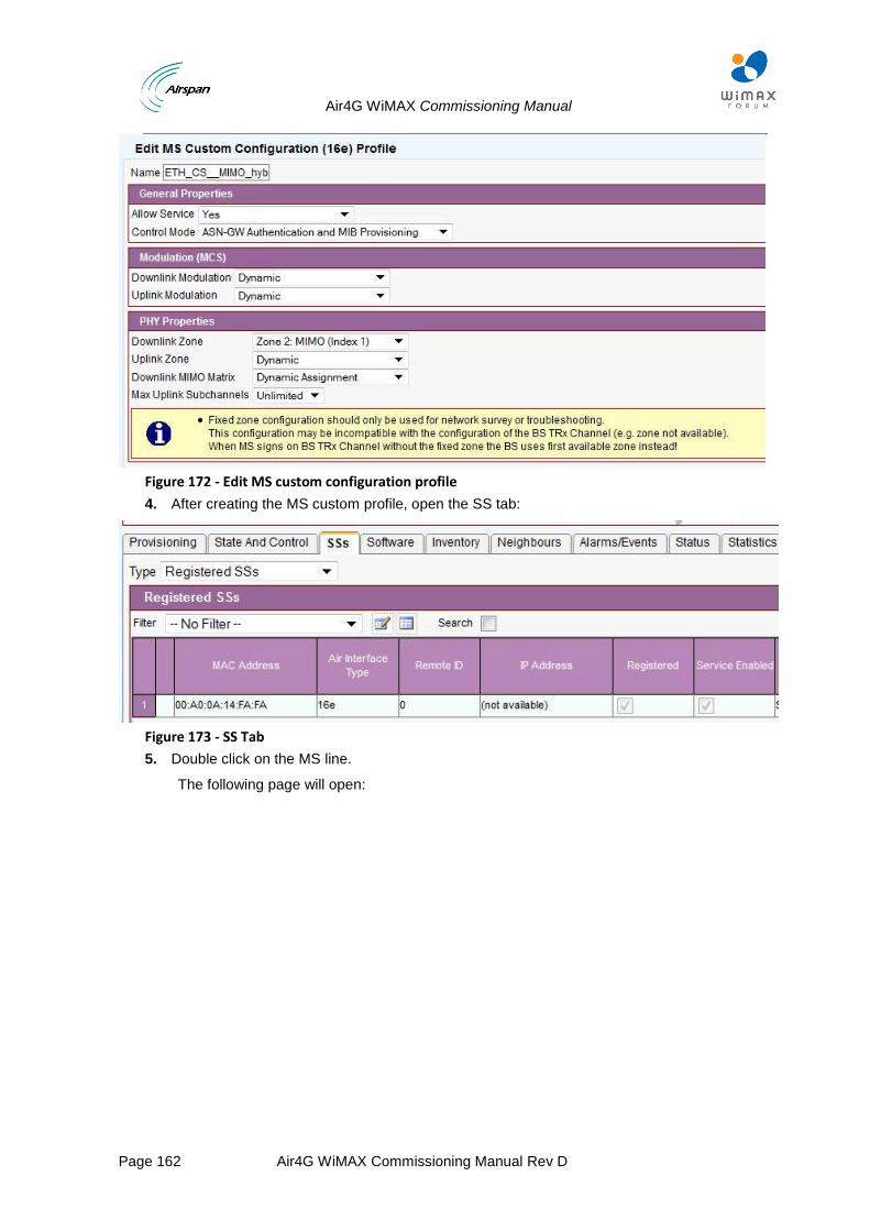
Air4G WiMAX Commissioning Manual
Page 162 Air4G WiMAX Commissioning Manual Rev D
Figure 172 - Edit MS custom configuration profile
4. After creating the MS custom profile, open the SS tab:
Figure 173 - SS Tab
5. Double click on the MS line.
The following page will open:
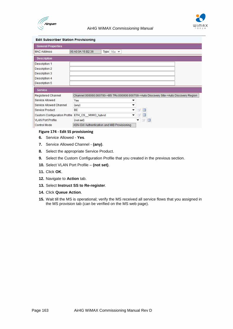
Air4G WiMAX Commissioning Manual
Page 163 Air4G WiMAX Commissioning Manual Rev D
Figure 174 - Edit SS provisioning
6. Service Allowed - Yes.
7. Service Allowed Channel - (any).
8. Select the appropriate Service Product.
9. Select the Custom Configuration Profile that you created in the previous section.
10. Select VLAN Port Profile – (not set).
11. Click OK.
12. Navigate to Action tab.
13. Select Instruct SS to Re-register.
14. Click Queue Action.
15. Wait till the MS is operational; verify the MS received all service flows that you assigned in the MS provision tab (can be verified on the MS web page).
Air4G WiMAX Commissioning Manual
Page 164 Air4G WiMAX Commissioning Manual Rev D
6 Service Products (QoS) Explanation & Creation
This section describes how the user data is being classified and conveyed over the WiMAX link.
Note: It is mandatory to create Service Products in order to convey traffic over the WiMAX link.
Classifiers
The classifier is an advanced filter. When a packet enters the queue it is being run through a set of user defined filters (i.e. Classifiers) that determine a number of options:
Packet is to be sent through a specific service-flow.
Packet is to be discarded.
Priority
The Priority section defines which classifier is examined first when a packet enters the queue. Ranges for the Priority are from 0 to 255. A classifier with a priority of 0 would be checked last and a classifier with a priority of 255 would be checked first.
Drop
In ASMAX it is possible to use the classifier to drop packets (similar to a basic firewall).
In WiMAX packet classification can be done on a number of parameters. A list of classification methods is shown below.
L2 Rules
This set of classifiers belongs to the third layer of the OSI model i.e. belongs to the network layer. They consist of:
TOS range (with Mask)
IP Protocol Number Source IP address (with Mask)
Destination IP address (with Mask)
Source port range.
L3 Rules
These set of classifiers belong to the second layer of the OSI model i.e. belong to the MAC layer. They consist of:
Source MAC address (with Mask)
Destination MAC address (with Mask)
Layer 3 protocol ID (for details see http://www.faqs.org/rfcs/rfc1042.html).
Service Classes
The service class is the actual “physical” Pipe on which the data is sent.
As in the world of plumbing, pipes come in different shapes and sizes. You can have a “wide” pipe carrying a large amount of payload (e.g. high MIR) or a small pipe for low volumes (e.g. low MIR).
The Service Class also defines the scheduling type.
In WiMAX we have 5 types of scheduling types: BE, RTPS, NRTPS, ERTPS and UGS.
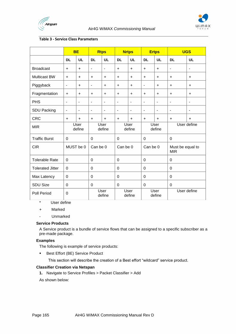
Air4G WiMAX Commissioning Manual
Page 165 Air4G WiMAX Commissioning Manual Rev D
Table 3 - Service Class Parameters
* User define
+ Marked
- Unmarked
Service Products
A Service product is a bundle of service flows that can be assigned to a specific subscriber as a pre-made package.
Examples
The following is example of service products:
Best Effort (BE) Service Product
This section will describe the creation of a Best effort “wildcard” service product.
Classifier Creation via Netspan
1. Navigate to Service Profiles > Packet Classifier > Add
As shown below:
BE Rtps Nrtps Ertps UGS
DL UL DL UL DL UL DL UL DL UL
Broadcast + + - - + + + + - -
Multicast BW + + + + + + + + + +
Piggyback - + - + + + - + + +
Fragmentation + + + + + + + + + +
PHS - - - - - - - - - -
SDU Packing - - - - - - - - - -
CRC + + + + + + + + + +
MIR User define
User define
User define
User define
User define
Traffic Burst 0 0 0 0 0
CIR MUST be 0 Can be 0 Can be 0 Can be 0 Must be equal to MIR
Tolerable Rate 0 0 0 0 0
Tolerated Jitter 0 0 0 0 0
Max Latency 0 0 0 0 0
SDU Size 0 0 0 0 0
Poll Period 0 User define
User define
User define
User define
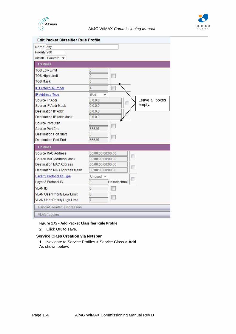
Air4G WiMAX Commissioning Manual
Page 166 Air4G WiMAX Commissioning Manual Rev D
Figure 175 - Add Packet Classifier Rule Profile
2. Click OK to save.
Service Class Creation via Netspan
1. Navigate to Service Profiles > Service Class > Add As shown below:
Leave all boxes empty.

Air4G WiMAX Commissioning Manual
Page 167 Air4G WiMAX Commissioning Manual Rev D
Figure 176 - Add Service Class
2. Click OK to save.
Enter the name
Select the scheduling type
Select the current policy that is supported by the scheduling type
ARQ - Not Requested
HARQ - Enabled
Type the MIR that is request for this Service class - in this example 10M
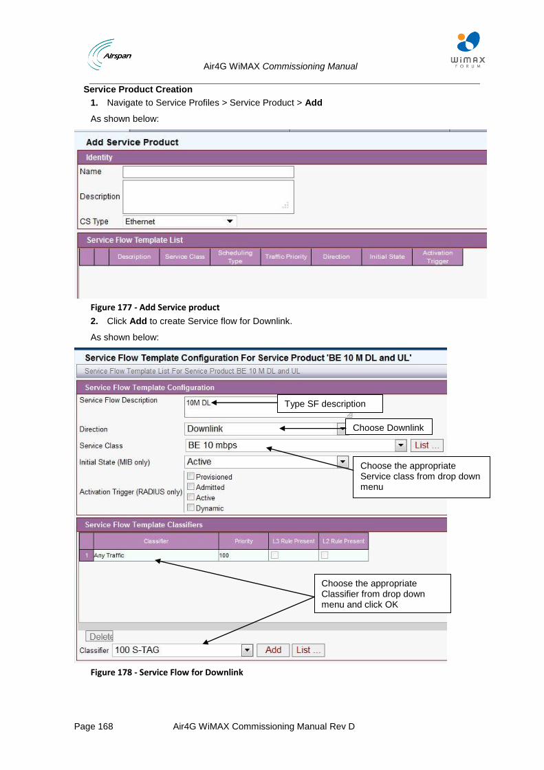
Air4G WiMAX Commissioning Manual
Page 168 Air4G WiMAX Commissioning Manual Rev D
Service Product Creation
1. Navigate to Service Profiles > Service Product > Add
As shown below:
Figure 177 - Add Service product
2. Click Add to create Service flow for Downlink.
As shown below:
Figure 178 - Service Flow for Downlink
Type SF description
Choose Downlink
Choose the appropriate Service class from drop down menu
Choose the appropriate Classifier from drop down menu and click OK
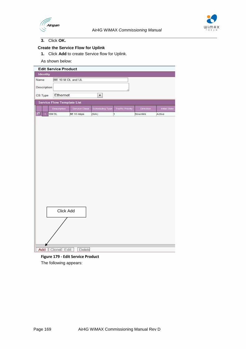
Air4G WiMAX Commissioning Manual
Page 169 Air4G WiMAX Commissioning Manual Rev D
3. Click OK.
Create the Service Flow for Uplink
1. Click Add to create Service flow for Uplink.
As shown below:
Figure 179 - Edit Service Product
The following appears:
Click Add
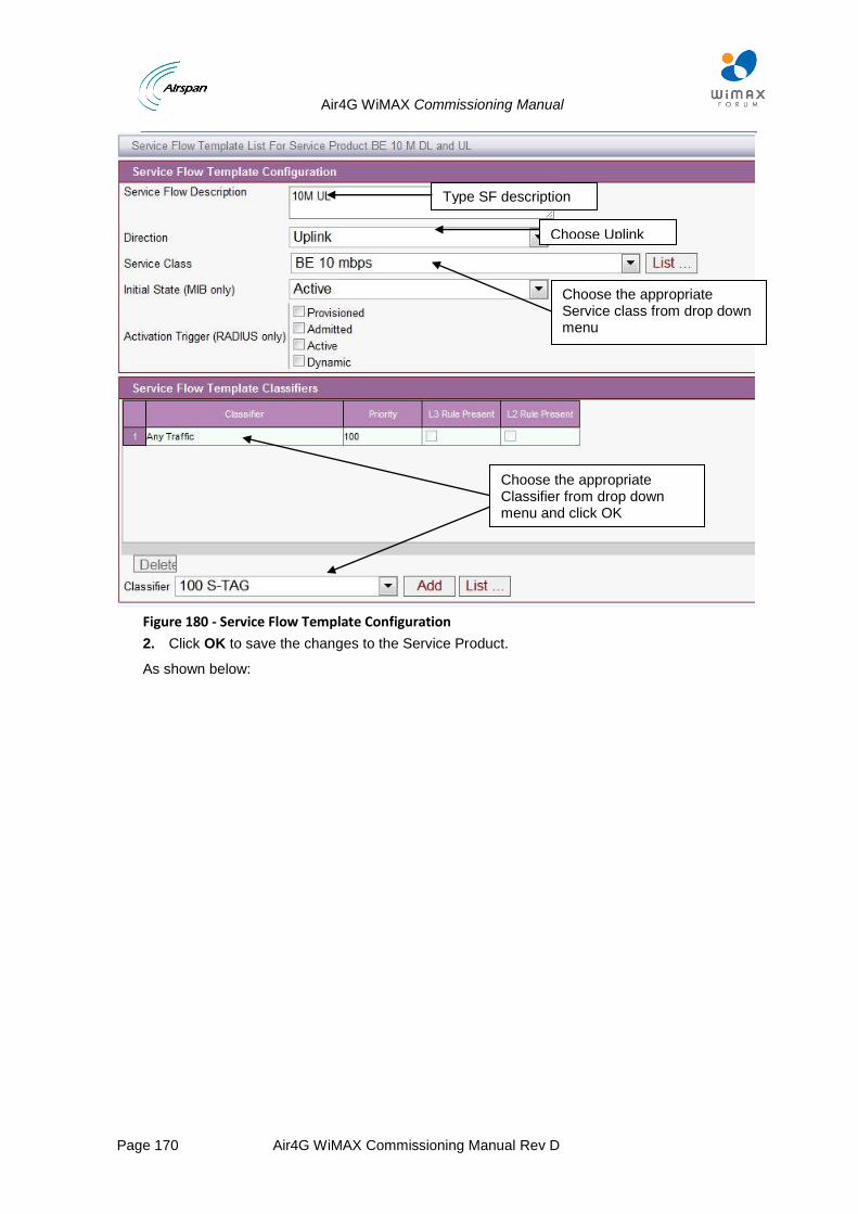
Air4G WiMAX Commissioning Manual
Page 170 Air4G WiMAX Commissioning Manual Rev D
Figure 180 - Service Flow Template Configuration
2. Click OK to save the changes to the Service Product.
As shown below:
Type SF description
Choose Uplink
Choose the appropriate Service class from drop down menu
Choose the appropriate Classifier from drop down menu and click OK
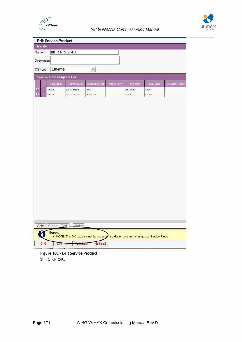
Air4G WiMAX Commissioning Manual
Page 171 Air4G WiMAX Commissioning Manual Rev D
Figure 181 - Edit Service Product
3. Click OK.
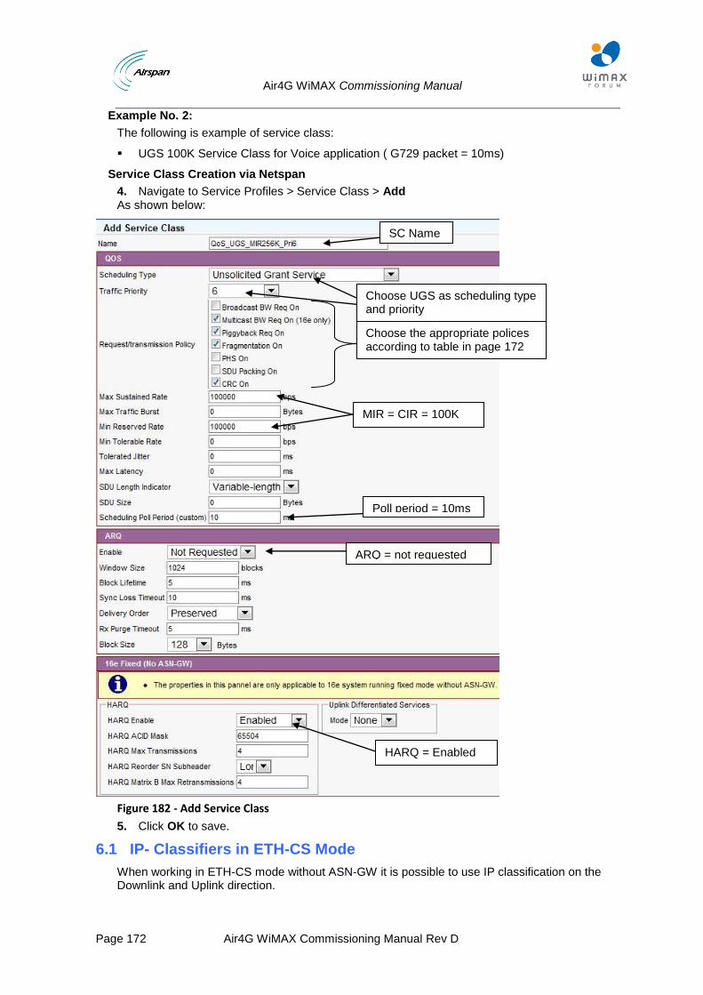
Air4G WiMAX Commissioning Manual
Page 172 Air4G WiMAX Commissioning Manual Rev D
Example No. 2:
The following is example of service class:
UGS 100K Service Class for Voice application ( G729 packet = 10ms)
Service Class Creation via Netspan
4. Navigate to Service Profiles > Service Class > Add As shown below:
Figure 182 - Add Service Class
5. Click OK to save.
6.1 IP- Classifiers in ETH-CS Mode
When working in ETH-CS mode without ASN-GW it is possible to use IP classification on the Downlink and Uplink direction.
SC Name
Choose UGS as scheduling type and priority
Choose the appropriate polices according to table in page 172
MIR = CIR = 100K
Poll period = 10ms
ARQ = not requested
HARQ = Enabled
Air4G WiMAX Commissioning Manual
Page 173 Air4G WiMAX Commissioning Manual Rev D
These rules MUST be applied when using this mode:
1. MS can have only Ethernet (L2) classification rules OR TCP/IP (L3/L4) classification rules, but not both (with one exception, see (4) below) – this rule applies ONLY on DL.
2. Non IP traffic cannot be classified using TCP/IP rules.
3. If MS has TCP/IP rules, it cannot have a wildcard rule (as it is implemented as an Ethernet rule). To work around this, define an IP address rule with an all zero mask (this is a de facto wildcard for any IP packet) – see the example below.
DL unicast ARP packets, which are required for normal network functionality, are not IP packets and hence cannot pass using TCP/IP rules.
Therefore, the BS allows one exception to the limitation defined in (1): A rule based on Ether type (L2) only is allowed alongside TCP/IP rules.
This allows one to configure a rule with Ethertype=0x806, which would allow traversal of those packets.
Examples
The following is example of service products:
Best Effort (BE) Service Product allowing any IP traffic from any IP to any IP.
This section will describe the creation of a Best effort “wildcard” IP service products.
Classifier Creation via Netspan
1. Navigate to Service Profiles > Packet Classifier > Add
As shown below:
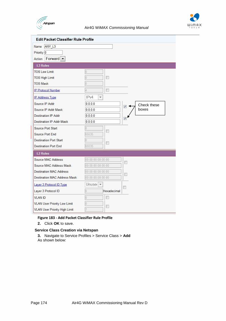
Air4G WiMAX Commissioning Manual
Page 174 Air4G WiMAX Commissioning Manual Rev D
Figure 183 - Add Packet Classifier Rule Profile
2. Click OK to save.
Service Class Creation via Netspan
3. Navigate to Service Profiles > Service Class > Add As shown below:
Check these boxes
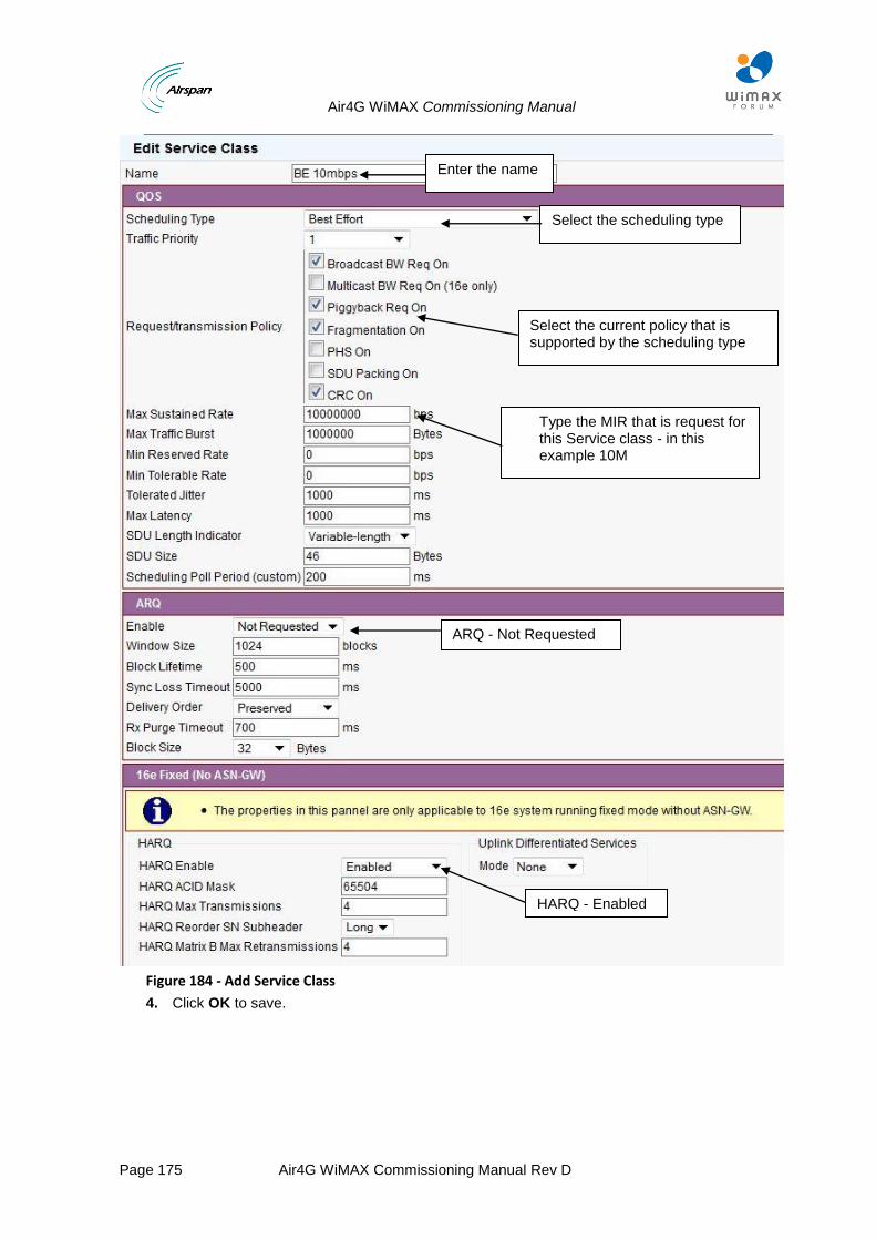
Air4G WiMAX Commissioning Manual
Page 175 Air4G WiMAX Commissioning Manual Rev D
Figure 184 - Add Service Class
4. Click OK to save.
Enter the name
Select the scheduling type
Select the current policy that is supported by the scheduling type
ARQ - Not Requested
HARQ - Enabled
Type the MIR that is request for this Service class - in this example 10M
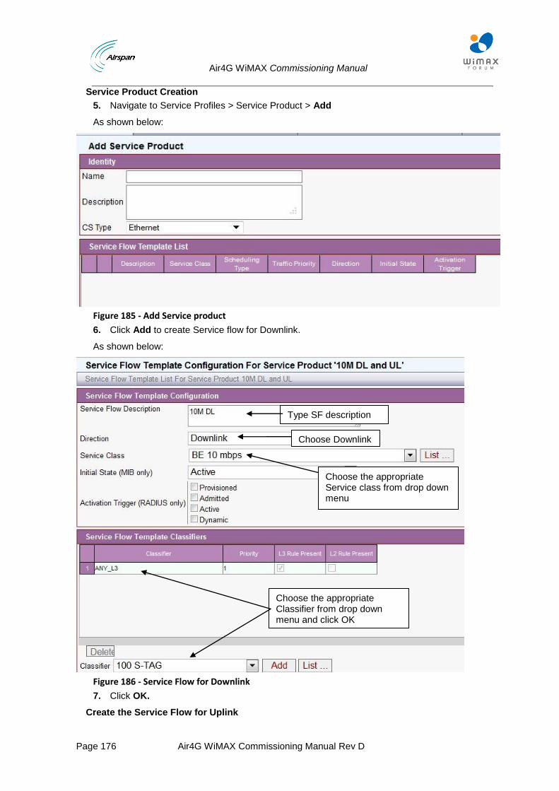
Air4G WiMAX Commissioning Manual
Page 176 Air4G WiMAX Commissioning Manual Rev D
Service Product Creation
5. Navigate to Service Profiles > Service Product > Add
As shown below:
Figure 185 - Add Service product
6. Click Add to create Service flow for Downlink.
As shown below:
Figure 186 - Service Flow for Downlink
7. Click OK.
Create the Service Flow for Uplink
Type SF description
Choose Downlink
Choose the appropriate Service class from drop down menu
Choose the appropriate Classifier from drop down menu and click OK
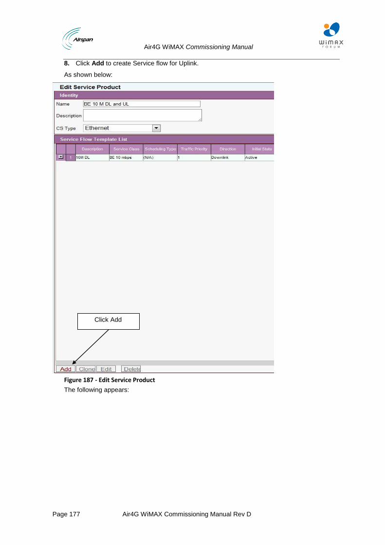
Air4G WiMAX Commissioning Manual
Page 177 Air4G WiMAX Commissioning Manual Rev D
8. Click Add to create Service flow for Uplink.
As shown below:
Figure 187 - Edit Service Product
The following appears:
Click Add
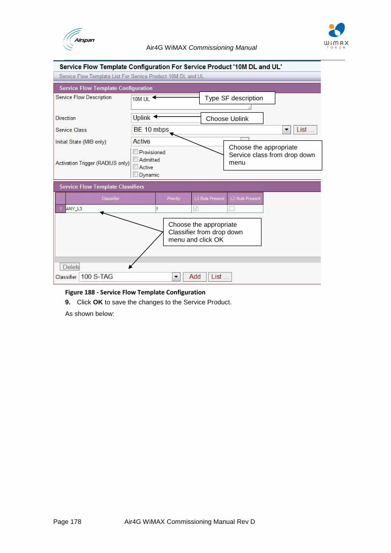
Air4G WiMAX Commissioning Manual
Page 178 Air4G WiMAX Commissioning Manual Rev D
Figure 188 - Service Flow Template Configuration
9. Click OK to save the changes to the Service Product.
As shown below:
Type SF description
Choose the appropriate Service class from drop down menu
Choose Uplink
Choose the appropriate Classifier from drop down menu and click OK

Air4G WiMAX Commissioning Manual
Page 179 Air4G WiMAX Commissioning Manual Rev D
Figure 189 - Edit Service Product
10. Click OK.
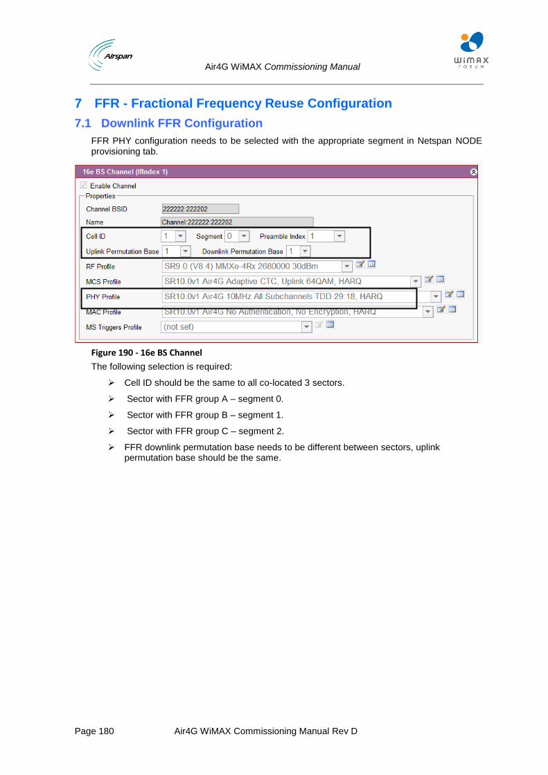
Air4G WiMAX Commissioning Manual
Page 180 Air4G WiMAX Commissioning Manual Rev D
7 FFR - Fractional Frequency Reuse Configuration
7.1 Downlink FFR Configuration
FFR PHY configuration needs to be selected with the appropriate segment in Netspan NODE provisioning tab.
Figure 190 - 16e BS Channel
The following selection is required:
Cell ID should be the same to all co-located 3 sectors.
Sector with FFR group A – segment 0.
Sector with FFR group B – segment 1.
Sector with FFR group C – segment 2.
FFR downlink permutation base needs to be different between sectors, uplink permutation base should be the same.
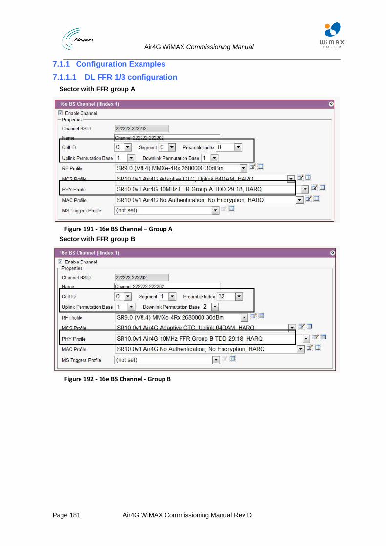
Air4G WiMAX Commissioning Manual
Page 181 Air4G WiMAX Commissioning Manual Rev D
7.1.1 Configuration Examples
7.1.1.1 DL FFR 1/3 configuration
Sector with FFR group A
Figure 191 - 16e BS Channel – Group A
Sector with FFR group B
Figure 192 - 16e BS Channel - Group B
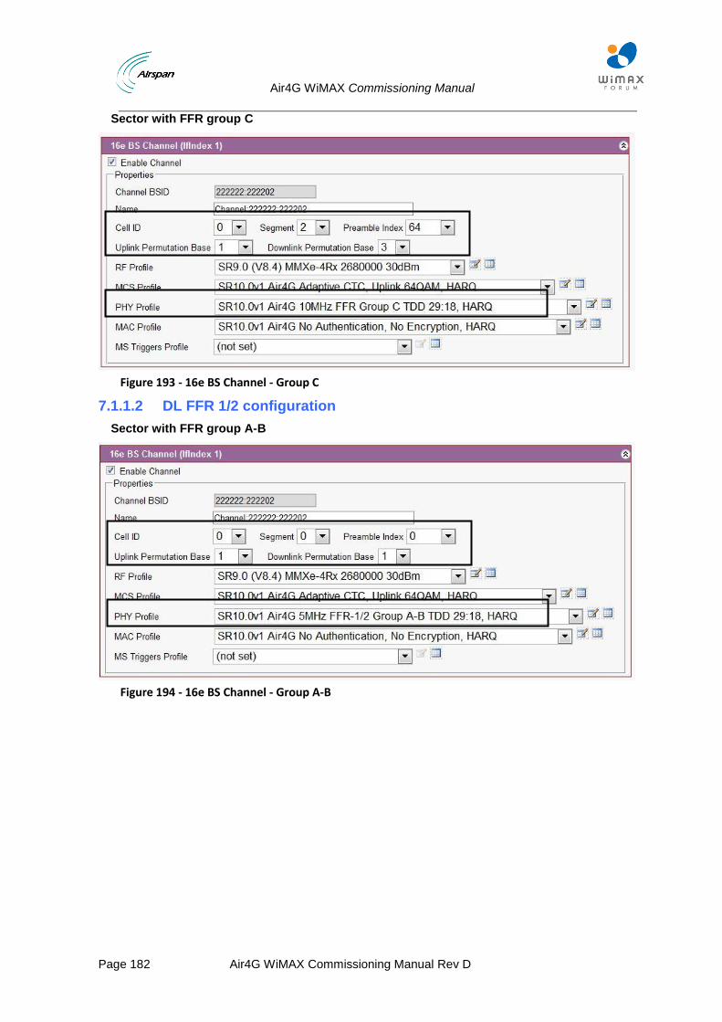
Air4G WiMAX Commissioning Manual
Page 182 Air4G WiMAX Commissioning Manual Rev D
Sector with FFR group C
Figure 193 - 16e BS Channel - Group C
7.1.1.2 DL FFR 1/2 configuration
Sector with FFR group A-B
Figure 194 - 16e BS Channel - Group A-B
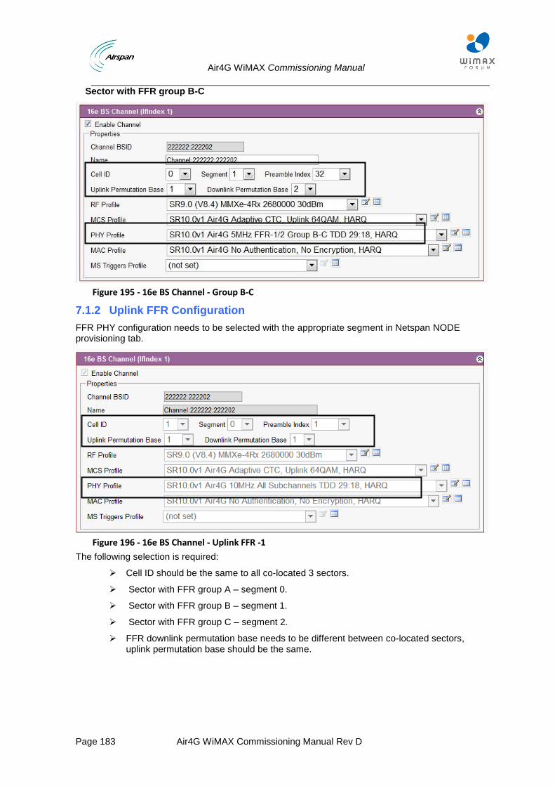
Air4G WiMAX Commissioning Manual
Page 183 Air4G WiMAX Commissioning Manual Rev D
Sector with FFR group B-C
Figure 195 - 16e BS Channel - Group B-C
7.1.2 Uplink FFR Configuration
FFR PHY configuration needs to be selected with the appropriate segment in Netspan NODE provisioning tab.
Figure 196 - 16e BS Channel - Uplink FFR -1
The following selection is required:
Cell ID should be the same to all co-located 3 sectors.
Sector with FFR group A – segment 0.
Sector with FFR group B – segment 1.
Sector with FFR group C – segment 2.
FFR downlink permutation base needs to be different between co-located sectors, uplink permutation base should be the same.
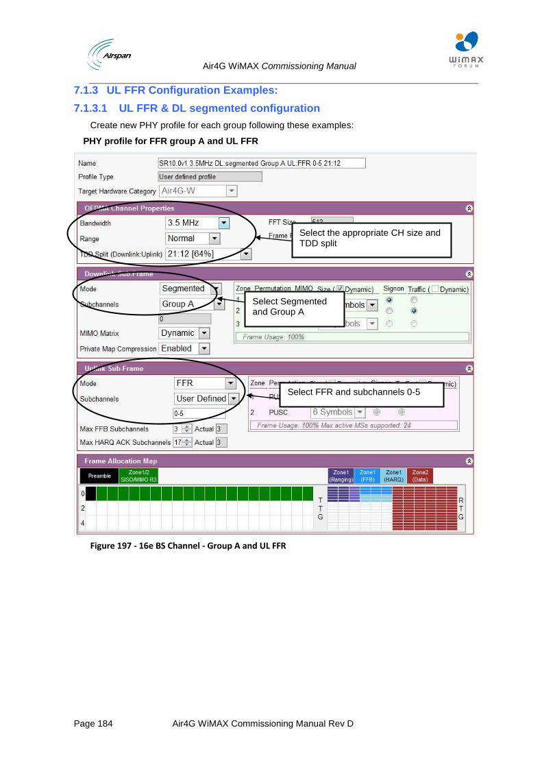
Air4G WiMAX Commissioning Manual
Page 184 Air4G WiMAX Commissioning Manual Rev D
7.1.3 UL FFR Configuration Examples:
7.1.3.1 UL FFR & DL segmented configuration
Create new PHY profile for each group following these examples:
PHY profile for FFR group A and UL FFR
Figure 197 - 16e BS Channel - Group A and UL FFR
Select the appropriate CH size and TDD split
Select Segmented and Group A
Select FFR and subchannels 0-5
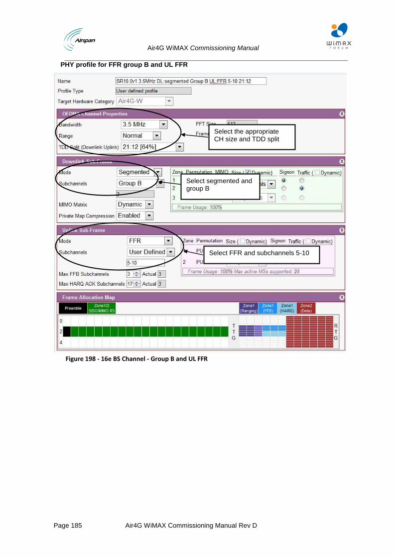
Air4G WiMAX Commissioning Manual
Page 185 Air4G WiMAX Commissioning Manual Rev D
PHY profile for FFR group B and UL FFR
Figure 198 - 16e BS Channel - Group B and UL FFR
Select the appropriate CH size and TDD split
Select segmented and group B
Select FFR and subchannels 5-10
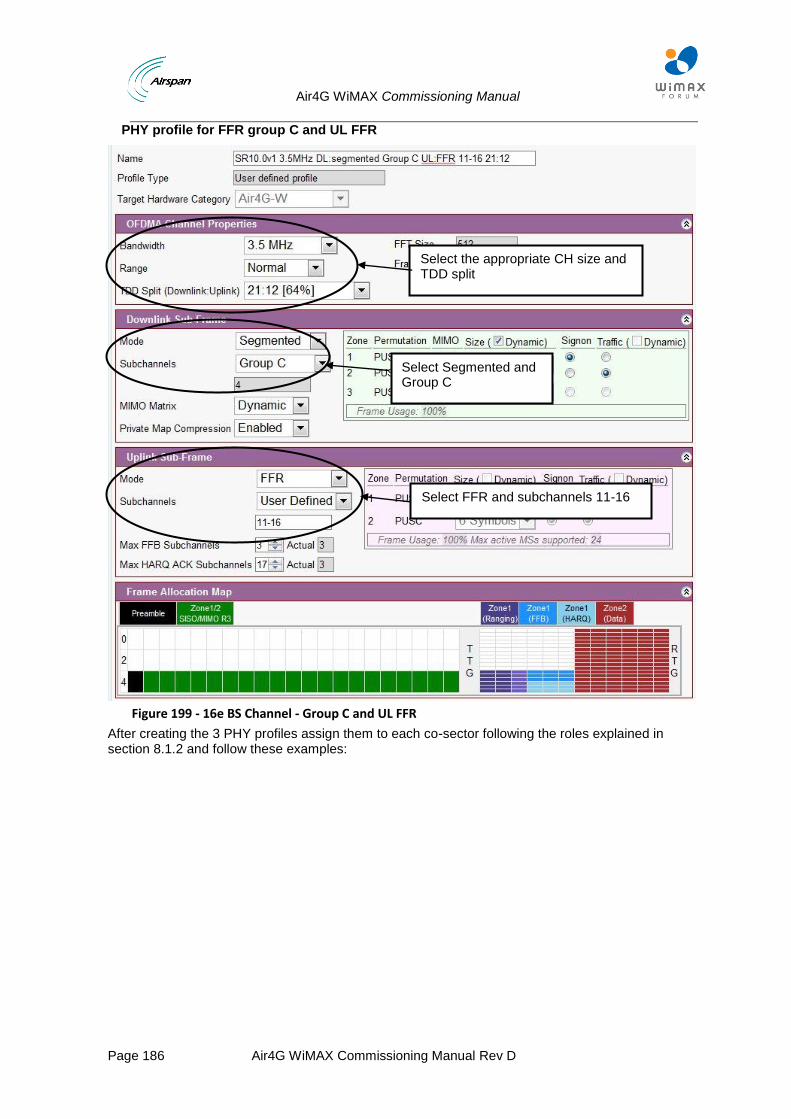
Air4G WiMAX Commissioning Manual
Page 186 Air4G WiMAX Commissioning Manual Rev D
PHY profile for FFR group C and UL FFR
Figure 199 - 16e BS Channel - Group C and UL FFR
After creating the 3 PHY profiles assign them to each co-sector following the roles explained in section 8.1.2 and follow these examples:
Select the appropriate CH size and TDD split
Select Segmented and Group C
Select FFR and subchannels 11-16
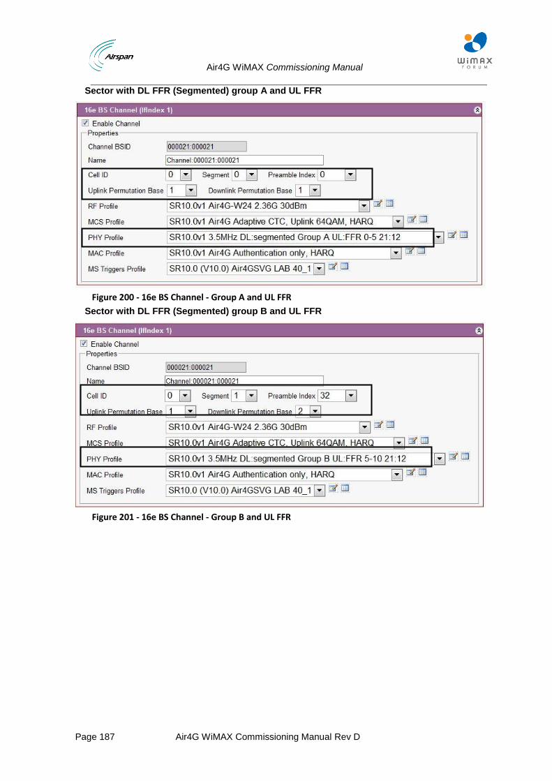
Air4G WiMAX Commissioning Manual
Page 187 Air4G WiMAX Commissioning Manual Rev D
Sector with DL FFR (Segmented) group A and UL FFR
Figure 200 - 16e BS Channel - Group A and UL FFR
Sector with DL FFR (Segmented) group B and UL FFR
Figure 201 - 16e BS Channel - Group B and UL FFR
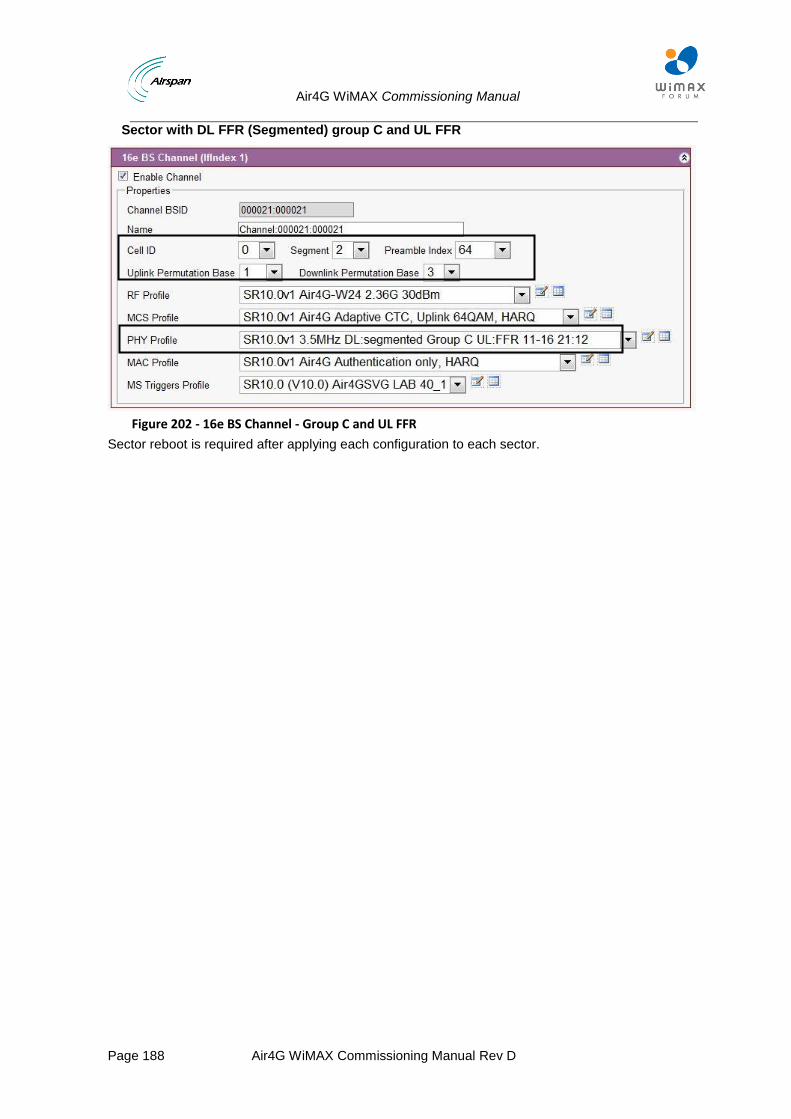
Air4G WiMAX Commissioning Manual
Page 188 Air4G WiMAX Commissioning Manual Rev D
Sector with DL FFR (Segmented) group C and UL FFR
Figure 202 - 16e BS Channel - Group C and UL FFR
Sector reboot is required after applying each configuration to each sector.
Air4G WiMAX Commissioning Manual
Page 189 Air4G WiMAX Commissioning Manual Rev D
8 DHCP Option 82
DHCP Option 82 provides a mechanism for generating IP addresses based on location the client device is in the network. Information about its location can be sent along with the request to the server. The DHCP server makes a decision on what IP should be assigned based on this information. In order to implement DHCP Option 82, the network must have the following equipment:
Standard DHCP client
Switch or router implementing Relay Agent with Option 82 support
DHCP server with Option 82 Support
When applying Option 82 for DHCP in Airspan’s Air4G – it acts as a switch implementing Relay agent Option 82.
The DHCP relay agent and Option 82 are defined in RFC 3046. Relay Agent Information option is inserted by the DHCP relay agent, in our case – the Air4G when forwarding client-originated DHCP packets to a DHCP server.
Servers recognizing the Relay Agent Information option may use the Information to implement IP address or other parameter assignment policies.
The Air4G and Mobile Station in conjunction, when enabled and configured for the DHCP relay agent, intercepts the DHCP requests, appends the circuit ID + remote ID into the Option 82 fields and forwards the request message to DHCP server
In Airspan’s Node profile settings Option 82 is operational ONLY via VLAN configuration and VLAN Bridge mode and requires PVID mode in subscriber stations.
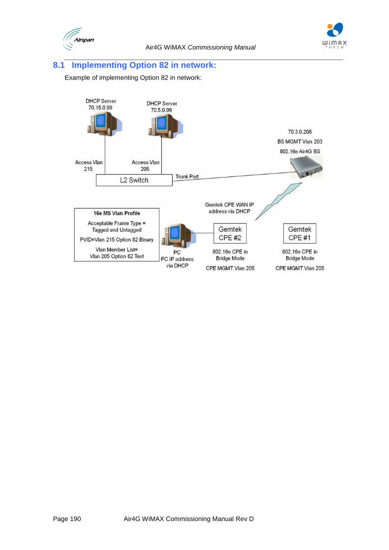
Air4G WiMAX Commissioning Manual
Page 190 Air4G WiMAX Commissioning Manual Rev D
8.1 Implementing Option 82 in network:
Example of implementing Option 82 in network:
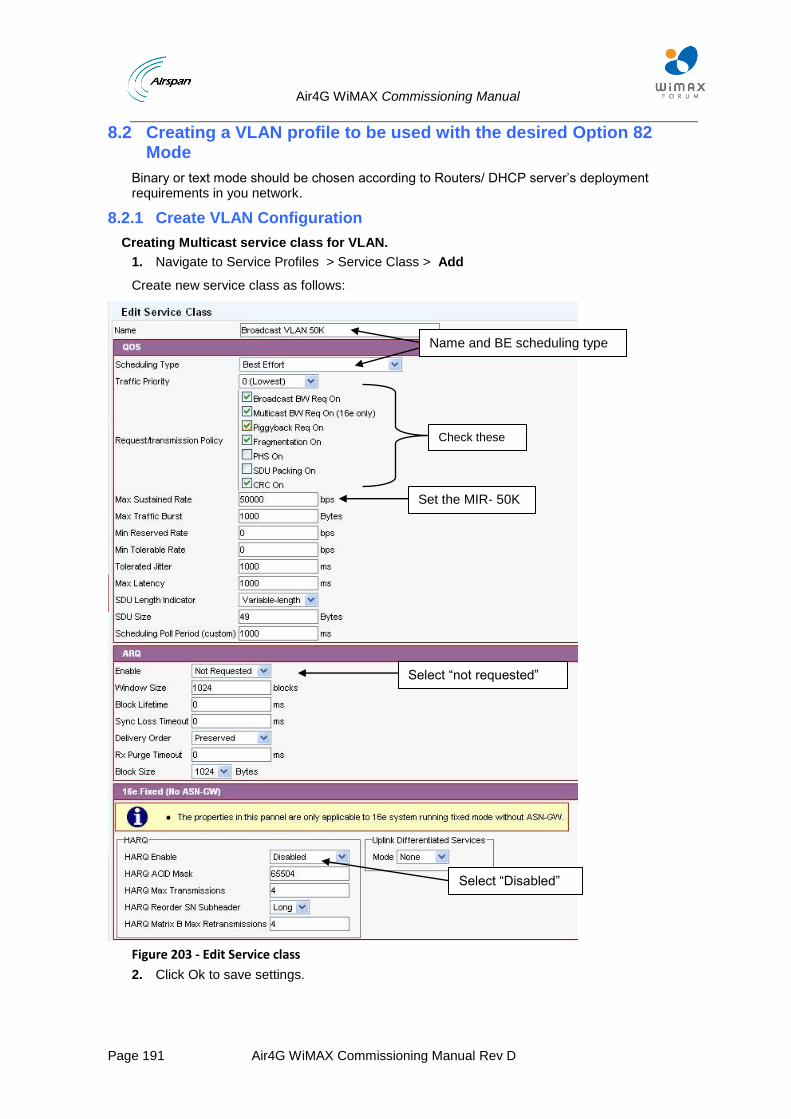
Air4G WiMAX Commissioning Manual
Page 191 Air4G WiMAX Commissioning Manual Rev D
8.2 Creating a VLAN profile to be used with the desired Option 82 Mode
Binary or text mode should be chosen according to Routers/ DHCP server’s deployment requirements in you network.
8.2.1 Create VLAN Configuration
Creating Multicast service class for VLAN.
1. Navigate to Service Profiles > Service Class > Add
Create new service class as follows:
Figure 203 - Edit Service class
2. Click Ok to save settings.
Name and BE scheduling type
Set the MIR- 50K
Select “Disabled”
Select “not requested”
Check these parameters
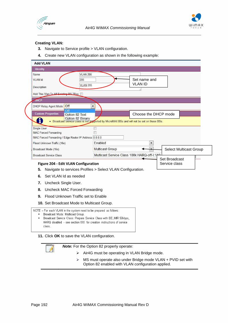
Air4G WiMAX Commissioning Manual
Page 192 Air4G WiMAX Commissioning Manual Rev D
Creating VLAN:
3. Navigate to Service profile > VLAN configuration.
4. Create new VLAN configuration as shown in the following example:
Figure 204 - Edit VLAN Configuration
5. Navigate to services Profiles > Select VLAN Configuration.
6. Set VLAN Id as needed
7. Uncheck Single User.
8. Uncheck MAC Forced Forwarding
9. Flood Unknown Traffic set to Enable
10. Set Broadcast Mode to Multicast Group.
11. Click OK to save the VLAN configuration.
Note: For the Option 82 properly operate:
Air4G must be operating in VLAN Bridge mode.
MS must operate also under Bridge mode VLAN + PVID set with Option 82 enabled with VLAN configuration applied.
Set name and VLAN ID
Set Broadcast Service class
Select Multicast Group
Choose the DHCP mode
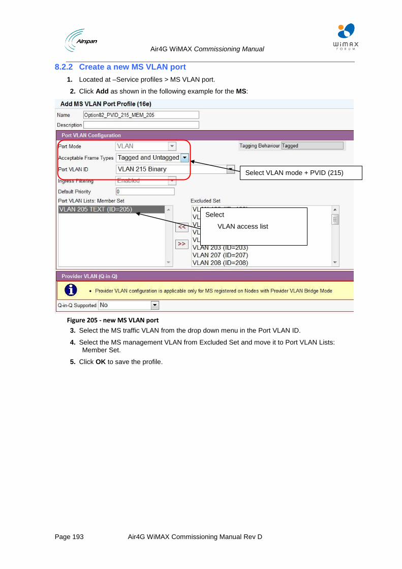
Air4G WiMAX Commissioning Manual
Page 193 Air4G WiMAX Commissioning Manual Rev D
8.2.2 Create a new MS VLAN port
1. Located at –Service profiles > MS VLAN port.
2. Click Add as shown in the following example for the MS:
Figure 205 - new MS VLAN port
3. Select the MS traffic VLAN from the drop down menu in the Port VLAN ID.
4. Select the MS management VLAN from Excluded Set and move it to Port VLAN Lists: Member Set.
5. Click OK to save the profile.
Select VLAN mode + PVID (215)
Select
VLAN access list
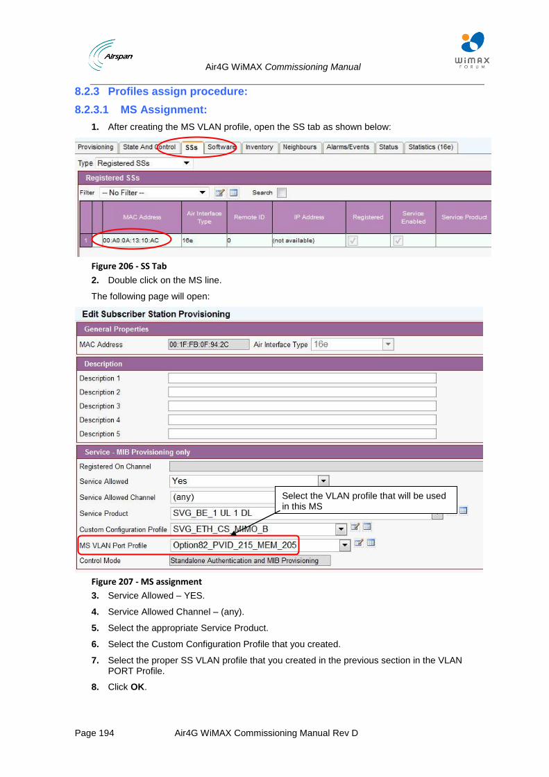
Air4G WiMAX Commissioning Manual
Page 194 Air4G WiMAX Commissioning Manual Rev D
8.2.3 Profiles assign procedure:
8.2.3.1 MS Assignment:
1. After creating the MS VLAN profile, open the SS tab as shown below:
Figure 206 - SS Tab
2. Double click on the MS line.
The following page will open:
Figure 207 - MS assignment
3. Service Allowed – YES.
4. Service Allowed Channel – (any).
5. Select the appropriate Service Product.
6. Select the Custom Configuration Profile that you created.
7. Select the proper SS VLAN profile that you created in the previous section in the VLAN PORT Profile.
8. Click OK.
Select the VLAN profile that will be used in this MS
Air4G WiMAX Commissioning Manual
Page 195 Air4G WiMAX Commissioning Manual Rev D
9 Applying IEEE 802.1Q-in-Q VLAN Tag
The IEEE 802.1Q-in-Q VLAN Tag purpose is to expand the VLAN space by tagging the tagged packets, thus producing a "double-tagged" frame. The expanded VLAN space allows the service provider to provide certain services, such as Internet access on specific VLANs for specific customers, and yet still allows the service provider to provide other types of services for their other customers on other VLANs.
Note: The IEEE 802.1Q-in-Q double tagged frame is called "S-tag". The IEEE 802.1Q "inner" tagged frame is called "C-tag".
This section will add the explanation to the different S / C tag Tagging and priority combinations allowed in the BS as well as MS levels Via Netspan settings.
Important guidelines regarding Q-in-Q feature:
1) ALL traffic related to MS coming out of the BS to the operator’s network will be Q-in-Q with the same outer Vlan Id.
2) BS management Vlan cannot be with Q-in-Q – it stays as a regular Vlan.
3) Both MS Vlan port profile and BS Vlan bridge profile have Q-in-Q enabled.
4) The MS Vlan port profile has all the inner Vlans ( C-Tag).
5) The BS Vlan bridge profile has ONLY the BS management Vlan and the Q-in-Q Outer Vlan ( S-Tag) in the Vlan list.
6) All the Vlans profiles including the outer Vlan profile have multicast CID.
a. The CPE implementation in Bridge Mode is to pass traffic (and Vlan tagged traffic) as is.
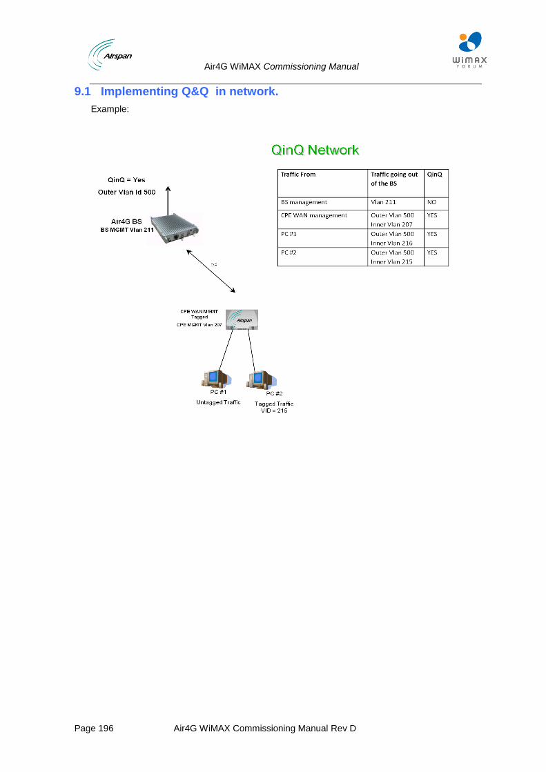
Air4G WiMAX Commissioning Manual
Page 196 Air4G WiMAX Commissioning Manual Rev D
9.1 Implementing Q&Q in network.
Example:
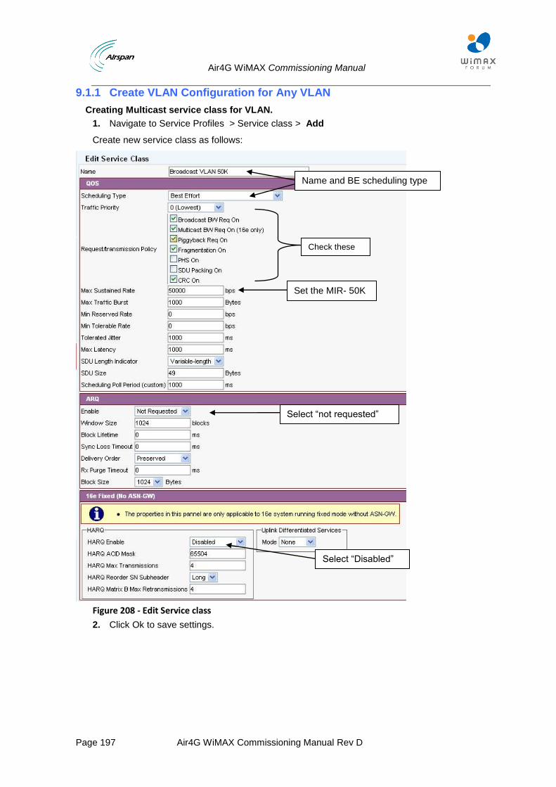
Air4G WiMAX Commissioning Manual
Page 197 Air4G WiMAX Commissioning Manual Rev D
9.1.1 Create VLAN Configuration for Any VLAN
Creating Multicast service class for VLAN.
1. Navigate to Service Profiles > Service class > Add
Create new service class as follows:
Figure 208 - Edit Service class
2. Click Ok to save settings.
Name and BE scheduling type
Set the MIR- 50K
Select “Disabled”
Select “not requested”
Check these parameters
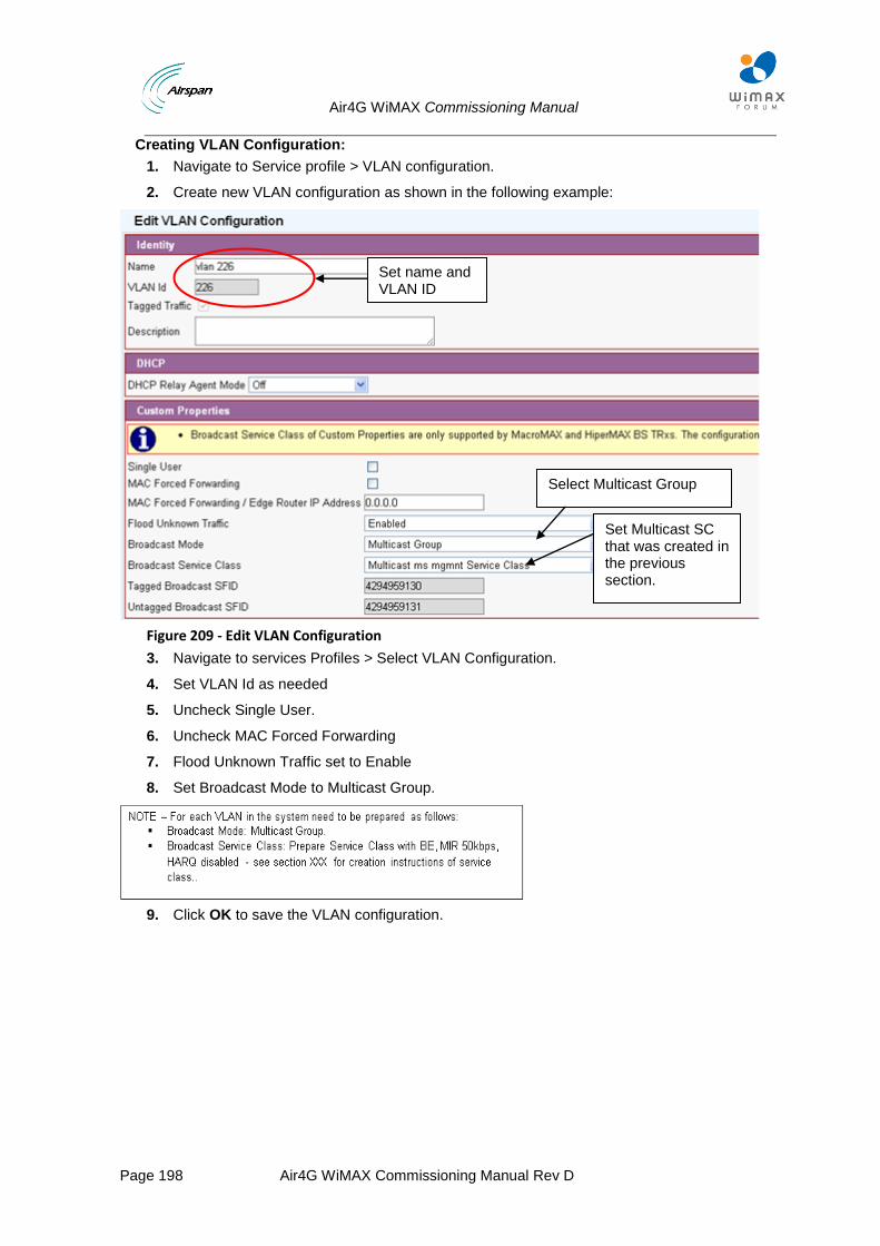
Air4G WiMAX Commissioning Manual
Page 198 Air4G WiMAX Commissioning Manual Rev D
Creating VLAN Configuration:
1. Navigate to Service profile > VLAN configuration.
2. Create new VLAN configuration as shown in the following example:
Figure 209 - Edit VLAN Configuration
3. Navigate to services Profiles > Select VLAN Configuration.
4. Set VLAN Id as needed
5. Uncheck Single User.
6. Uncheck MAC Forced Forwarding
7. Flood Unknown Traffic set to Enable
8. Set Broadcast Mode to Multicast Group.
9. Click OK to save the VLAN configuration.
Set name and VLAN ID
Select Multicast Group
Set Multicast SC that was created in the previous section.
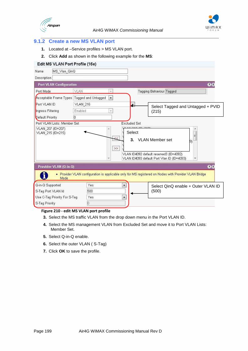
Air4G WiMAX Commissioning Manual
Page 199 Air4G WiMAX Commissioning Manual Rev D
9.1.2 Create a new MS VLAN port
1. Located at –Service profiles > MS VLAN port.
2. Click Add as shown in the following example for the MS:
Figure 210 - edit MS VLAN port profile
3. Select the MS traffic VLAN from the drop down menu in the Port VLAN ID.
4. Select the MS management VLAN from Excluded Set and move it to Port VLAN Lists: Member Set.
5. Select Q-in-Q enable.
6. Select the outer VLAN ( S-Tag)
7. Click OK to save the profile.
Select Tagged and Untagged + PVID (215)
Select
3. VLAN Member set
Select QinQ enable + Outer VLAN ID (500)
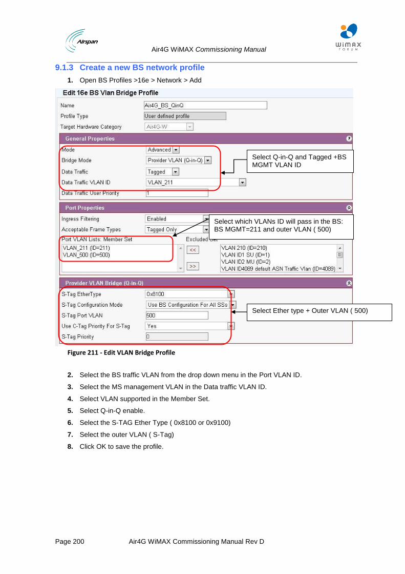
Air4G WiMAX Commissioning Manual
Page 200 Air4G WiMAX Commissioning Manual Rev D
9.1.3 Create a new BS network profile
1. Open BS Profiles >16e > Network > Add
Figure 211 - Edit VLAN Bridge Profile
2. Select the BS traffic VLAN from the drop down menu in the Port VLAN ID.
3. Select the MS management VLAN in the Data traffic VLAN ID.
4. Select VLAN supported in the Member Set.
5. Select Q-in-Q enable.
6. Select the S-TAG Ether Type ( 0x8100 or 0x9100)
7. Select the outer VLAN ( S-Tag)
8. Click OK to save the profile.
Select Q-in-Q and Tagged +BS MGMT VLAN ID
Select which VLANs ID will pass in the BS: BS MGMT=211 and outer VLAN ( 500)
Select Ether type + Outer VLAN ( 500)
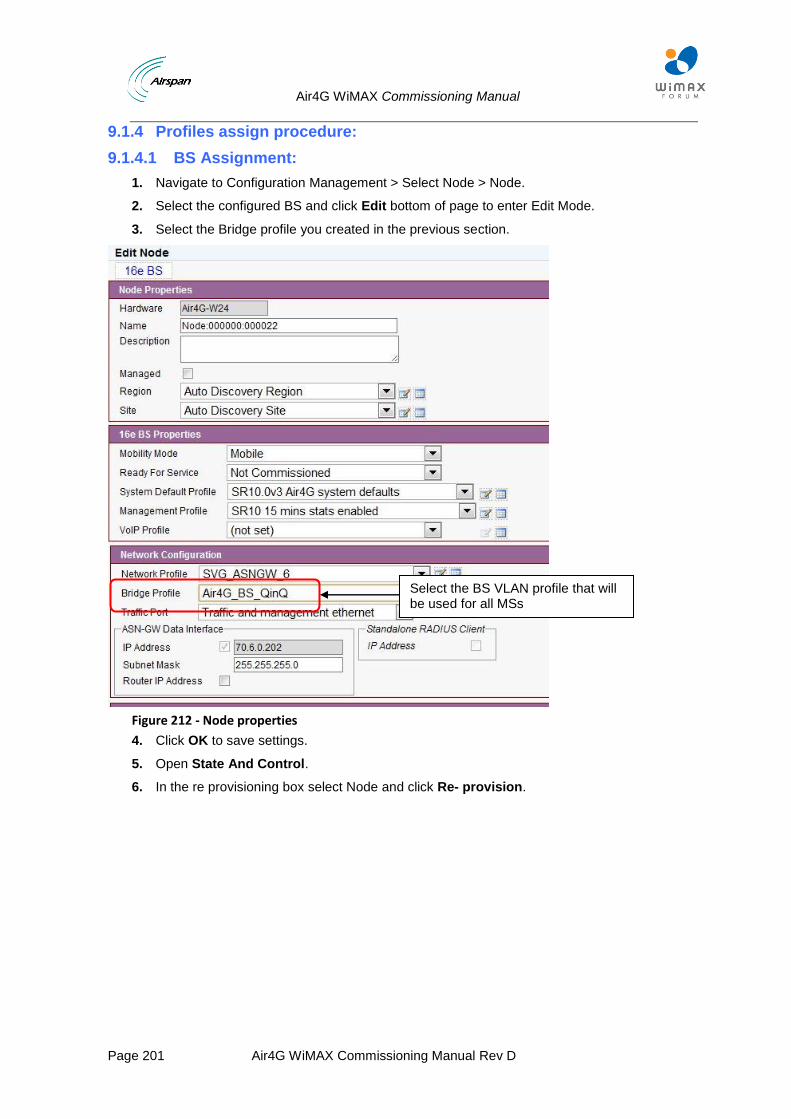
Air4G WiMAX Commissioning Manual
Page 201 Air4G WiMAX Commissioning Manual Rev D
9.1.4 Profiles assign procedure:
9.1.4.1 BS Assignment:
1. Navigate to Configuration Management > Select Node > Node.
2. Select the configured BS and click Edit bottom of page to enter Edit Mode.
3. Select the Bridge profile you created in the previous section.
Figure 212 - Node properties
4. Click OK to save settings.
5. Open State And Control.
6. In the re provisioning box select Node and click Re- provision.
Select the BS VLAN profile that will be used for all MSs
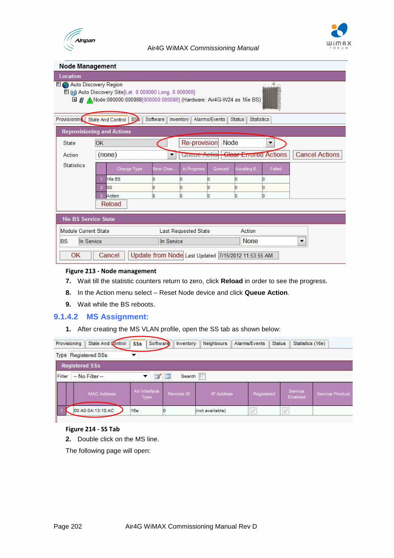
Air4G WiMAX Commissioning Manual
Page 202 Air4G WiMAX Commissioning Manual Rev D
Figure 213 - Node management
7. Wait till the statistic counters return to zero, click Reload in order to see the progress.
8. In the Action menu select – Reset Node device and click Queue Action.
9. Wait while the BS reboots.
9.1.4.2 MS Assignment:
1. After creating the MS VLAN profile, open the SS tab as shown below:
Figure 214 - SS Tab
2. Double click on the MS line.
The following page will open:
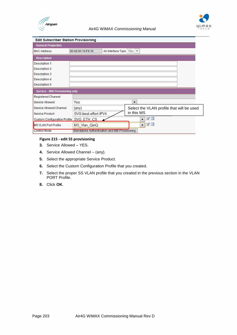
Air4G WiMAX Commissioning Manual
Page 203 Air4G WiMAX Commissioning Manual Rev D
Figure 215 - edit SS provisioning
3. Service Allowed – YES.
4. Service Allowed Channel – (any).
5. Select the appropriate Service Product.
6. Select the Custom Configuration Profile that you created.
7. Select the proper SS VLAN profile that you created in the previous section in the VLAN PORT Profile.
8. Click OK.
Select the VLAN profile that will be used in this MS
Air4G WiMAX Commissioning Manual
Page 204 Air4G WiMAX Commissioning Manual Rev D
10 Dual Sector Configuration
• This allows a single BS sector to operate two 10MHz MIMO RF Channels or two 7MHz MIMO RF Channels
• An operator can double network capacity without adding additional BS infrastructure
Note: This feature is supported only on Air4Gp.
Note: The Node’s name in Netspan will be by default the first sector’s BSID..
10.1 Discovering the BS in Netspan
10.1.1 Set BS Management IP & BSID via Web Page
The following are the steps to the BS via its WEB interface.
Wait for the BS to complete the boot sequence.
Ensure that your Web browser with which you want to access the Web-based Management is active.
To connect to Air4G via the WEB interface:
1. Open web browser ant type the BS address.
IP address – 192.168.0.100 (255.0.0.0) User name – Air4Gweb Password – thhr49Key
2. Click Submit The following is displayed:

Air4G WiMAX Commissioning Manual
Page 205 Air4G WiMAX Commissioning Manual Rev D
Figure 216 - BS Config
3. Specify the BS ID per each sector.
4. Click Submit.
5. Navigate to “Mgmt IP Config” and modify the IP address according to your network.
Write the BS ID for each channel
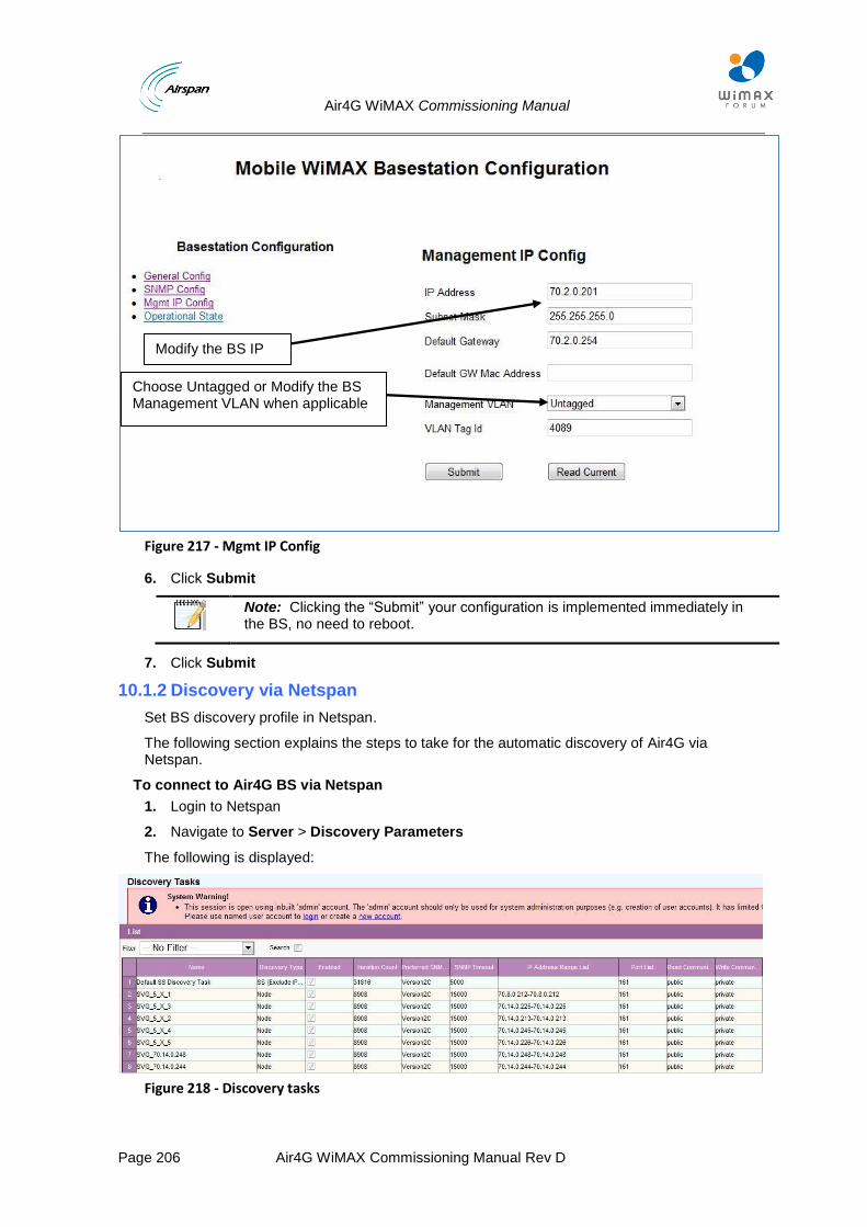
Air4G WiMAX Commissioning Manual
Page 206 Air4G WiMAX Commissioning Manual Rev D
Figure 217 - Mgmt IP Config
6. Click Submit
Note: Clicking the “Submit” your configuration is implemented immediately in the BS, no need to reboot.
7. Click Submit
10.1.2 Discovery via Netspan
Set BS discovery profile in Netspan.
The following section explains the steps to take for the automatic discovery of Air4G via Netspan.
To connect to Air4G BS via Netspan
1. Login to Netspan
2. Navigate to Server > Discovery Parameters
The following is displayed:
Figure 218 - Discovery tasks
Modify the BS IP IPIP
Choose Untagged or Modify the BS Management VLAN when applicable

Air4G WiMAX Commissioning Manual
Page 207 Air4G WiMAX Commissioning Manual Rev D
3. Click Add
4. Define:
a. Name.
b. Write Community.
Note: This should be same as was configured before on the BS.
5. Read Only Community – define a Community then click Add (on right side of the field).
Note: This should be same as was configured before on the BS.
6. Port – enter 161 then click Add (on right side of the field), as shown below:
7. Click Add in the “Discovery Target IP Address Ranges “section – this will create range. For example – Start address = 192.168.0.100 and End Address=192.168.0.101
8. Select within the values area to set (define) both to the required IP address (of the BS)
9. Click OK, as shown below:
Figure 219 - Edit Discovery tasks parameters
10. Click OK and wait till you see the new BS in the “ configuration management > BS > Node, as shown below:
Enter the BS IP address

Air4G WiMAX Commissioning Manual
Page 208 Air4G WiMAX Commissioning Manual Rev D
Figure 220 - discovery target
The Air4G BS is now “discovered” by Netspan and is ready for additional configuration, provisioning and adaptations.
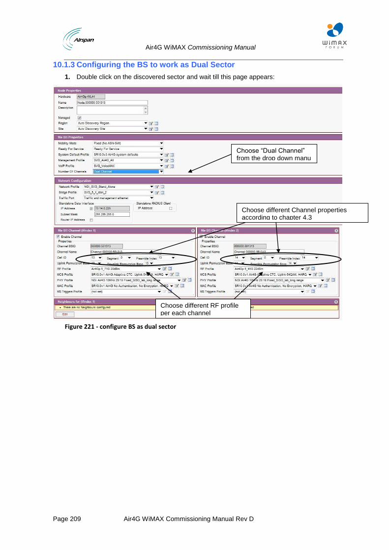
Air4G WiMAX Commissioning Manual
Page 209 Air4G WiMAX Commissioning Manual Rev D
10.1.3 Configuring the BS to work as Dual Sector
1. Double click on the discovered sector and wait till this page appears:
Figure 221 - configure BS as dual sector
Choose “Dual Channel” from the drop down manu
Choose different RF profile per each channel
Choose different Channel properties according to chapter 4.3
Air4G WiMAX Commissioning Manual
Page 210 Air4G WiMAX Commissioning Manual Rev D
11 Dual MAC-PHY Configuration
• This allows a single BS sector to operate two adjacent 10MHz MIMO RF Channels or two
7MHz MIMO RF Channels
• An operator can double network capacity without adding additional BS infrastructure
Note: This feature is not supported on Air4Gs.
Note: The Node’s name in Netspan will be default the first sector’s BSID.
11.1 Discovering the BS in Netspan
11.1.1 Set BS Management IP & BSID via Web Page
The following are the steps to the BS via its WEB interface.
Wait for the bs to complete the boot sequence!
Ensure that your Web browser with which you want to access the Web-based Management is active.
To connect to Air4G via the WEB interface:
1. Open web browser ant type the BS address.
IP address – 192.168.0.100 (255.0.0.0) User name – Air4Gweb Password – thhr49Key
2. Click Submit The following is displayed:
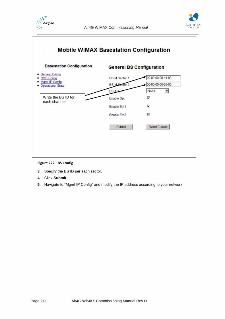
Air4G WiMAX Commissioning Manual
Page 211 Air4G WiMAX Commissioning Manual Rev D
Figure 222 - BS Config
3. Specify the BS ID per each sector.
4. Click Submit.
5. Navigate to “Mgmt IP Config” and modify the IP address according to your network.
Write the BS ID for each channel

Air4G WiMAX Commissioning Manual
Page 212 Air4G WiMAX Commissioning Manual Rev D
Figure 223 - Mgmt IP Config
6. Click Submit
Note: Clicking the “Submit” your configuration is implemented immediately in the BS, no need to reboot.
7. Click Submit
11.1.2 Discovery via Netspan
Set BS discovery profile in Netspan.
The following section explains the steps to take for the automatic discovery of Air4G via Netspan.
To connect to Air4G BS via Netspan
1. Login to Netspan
2. Navigate to Server > Discovery Parameters
The following is displayed:
Figure 224 - Discovery tasks
Modify the BS IP IPIP
Choose Untagged or Modify the BS Management VLAN when applicable
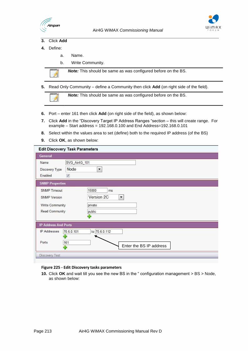
Air4G WiMAX Commissioning Manual
Page 213 Air4G WiMAX Commissioning Manual Rev D
3. Click Add
4. Define:
a. Name.
b. Write Community.
Note: This should be same as was configured before on the BS.
5. Read Only Community – define a Community then click Add (on right side of the field).
Note: This should be same as was configured before on the BS.
6. Port – enter 161 then click Add (on right side of the field), as shown below:
7. Click Add in the “Discovery Target IP Address Ranges “section – this will create range. For example – Start address = 192.168.0.100 and End Address=192.168.0.101
8. Select within the values area to set (define) both to the required IP address (of the BS)
9. Click OK, as shown below:
Figure 225 - Edit Discovery tasks parameters
10. Click OK and wait till you see the new BS in the “ configuration management > BS > Node, as shown below:
Enter the BS IP address

Air4G WiMAX Commissioning Manual
Page 214 Air4G WiMAX Commissioning Manual Rev D
Figure 226 - discovery target
The Air4G BS is now “discovered” by Netspan and is ready for additional configuration, provisioning and adaptations.
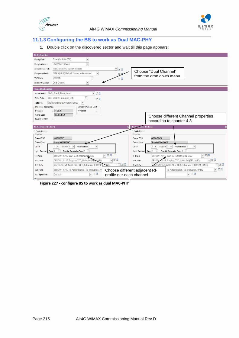
Air4G WiMAX Commissioning Manual
Page 215 Air4G WiMAX Commissioning Manual Rev D
11.1.3 Configuring the BS to work as Dual MAC-PHY
1. Double click on the discovered sector and wait till this page appears:
Figure 227 - configure BS to work as dual MAC-PHY
Choose “Dual Channel” from the drop down manu
Choose different adjacent RF profile per each channel
Choose different Channel properties according to chapter 4.3
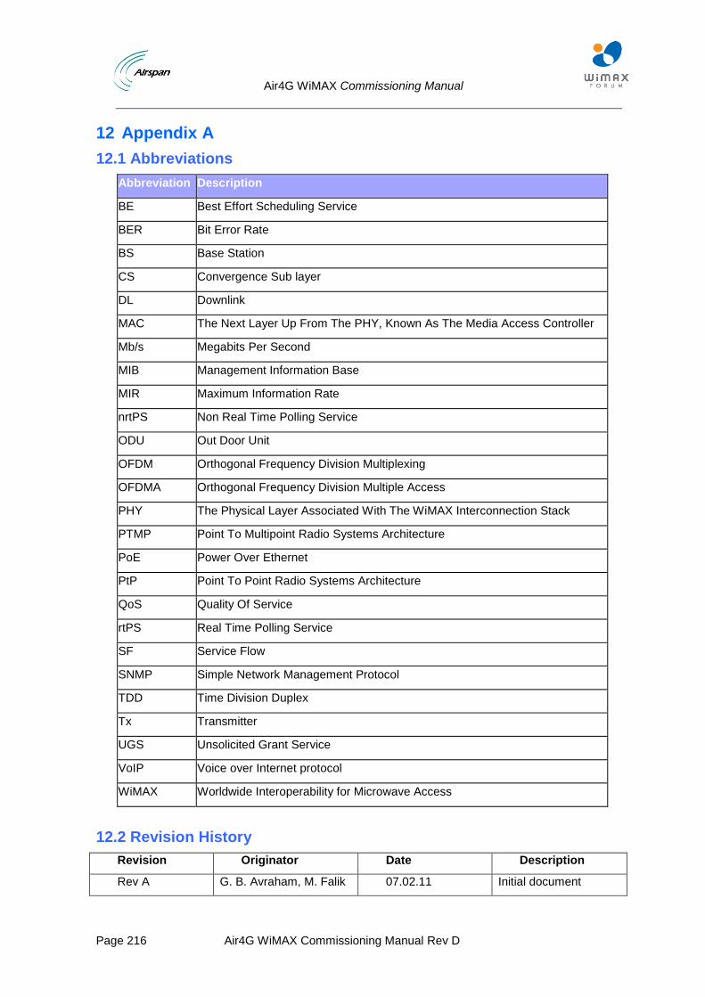
Air4G WiMAX Commissioning Manual
Page 216 Air4G WiMAX Commissioning Manual Rev D
12 Appendix A
12.1 Abbreviations
Abbreviation Description
BE Best Effort Scheduling Service
BER Bit Error Rate
BS Base Station
CS Convergence Sub layer
DL Downlink
MAC The Next Layer Up From The PHY, Known As The Media Access Controller
Mb/s Megabits Per Second
MIB Management Information Base
MIR Maximum Information Rate
nrtPS Non Real Time Polling Service
ODU Out Door Unit
OFDM Orthogonal Frequency Division Multiplexing
OFDMA Orthogonal Frequency Division Multiple Access
PHY The Physical Layer Associated With The WiMAX Interconnection Stack
PTMP Point To Multipoint Radio Systems Architecture
PoE Power Over Ethernet
PtP Point To Point Radio Systems Architecture
QoS Quality Of Service
rtPS Real Time Polling Service
SF Service Flow
SNMP Simple Network Management Protocol
TDD Time Division Duplex
Tx Transmitter
UGS Unsolicited Grant Service
VoIP Voice over Internet protocol
WiMAX Worldwide Interoperability for Microwave Access
12.2 Revision History
Revision Originator Date Description
Rev A G. B. Avraham, M. Falik 07.02.11 Initial document
Air4G WiMAX Commissioning Manual
Page 217 Air4G WiMAX Commissioning Manual Rev D
Revision Originator Date Description
Rev B S. Kadar, M. Falik 14.02.11 Ver 2
Rev C R. Baskenazi, M. Falik 09.02.12 SR 9.61/9.7 Format change, additions & updates
Rev D R. Baskenazi, M. Falik 08.11.12 SR 10.5 additions & updates
12.3 Contact Information
Customer Service Help-Desk for customer service emergency
Airspan Networks have introduced the Airspan Tracker application to enable prompt and efficient Customer Support services.
If you do not have an Airspan Tracker account, please obtain login credentials by filling-in the form in the main page "Register New Account".
Worldwide Headquarters:
Airspan Networks Inc.
777, Yamato Road, Suite 310,
Boca Raton, FL 33431, USA
Tel: +1 561 893 8670
www.airspan.com
Feedback:
To provide feedback on this document, please send comments to the following email address: [email protected]