AIR TEST PROCEDURE MANUAL FOR FOOTHILLS PIPE …€¦ · · 2017-08-18TEST PROCEDURE MANUAL FOR...
42
AIR TEST PROCEDURE MANUAL FOR FOOTHILLS PIPE LINES (SOUTH B.C.) LTD.
Transcript of AIR TEST PROCEDURE MANUAL FOR FOOTHILLS PIPE …€¦ · · 2017-08-18TEST PROCEDURE MANUAL FOR...

AIR
TEST PROCEDURE MANUAL
FOR
FOOTHILLS PIPE LINES (SOUTH B.C.) LTD.

AIR
TEST PROCEDURE MANUAL
FOR
FOOTHILLS PIPE LINES (SOUTH B.C.) LTD.
October 1980
TABLE OF CONTENTS
PAGE
SECTION 1 INTRODUCTION 1
SECTION 2 PIPELINE CLEANING AND GAUGING 4
SECTION 3 FINAL AIR AND LEAK TEST 7
SECTION 4 TEST RECORDS 14
APPENDIX I PIPE SPECIFICATIONS AND TEST PRESSURES 17
APPENDIX II TEST SECTIONS 18
APPENDIX III TEST FORMS 19
APPENDIX IV TEST INSTRUJ1.1ENTS 25
APPENDIX v PIG RUN SEQUENCE 27
DRAWINGS 28
INTRODUCTION
A. PURPOSE AND SCOPE
This manual has been prepared to establish a procedure
for air testing three test sections in prebuild loop #2
of OWNER'S 914rnrn Pipeline through the southeast corner of
British Columbia. This manual is supplemental to the
requirements within the pipeline construction contract
for Hydrostatic Strength and Leak Test.
All air testing shall meet the requirements of Part III
of the National Energy Board Act Gas Pipeline
Regulations.
B. TERMINOLOGY
OWNER
MANAGER
CONTRACTOR
ANSI
ASTM
CSA
-2-
Foothills Pipe Lines (South B.C.)
Ltd., or its designated agents.
Alberta Natural Gas Company Ltd,
acting as agent for OWNER and its
Resident Manager, his assistants,
inspectors, representatives,
agents and such other staff as may
from time to time be designated as
such by written notice given by
MANAGER to CONTRACTOR.
The party contracting to perform
the hydrostatic testing.
American National Standards
Institute.
American Society for Testing and
Materials.
Canadian Standards Association.

-3-
B. TERMINOLOGY (continued)
TEMP temperature oc degrees celsius
I.D. inside diameter
O.D. outside diameter
W.T. wall thickness
s second
min minute
h hour
1 litre
VOL. volume
MPa megapascals
kPa kilopascals
mm millimeters
m meters
km kilometers

-4-
PIPELINE CLEANING AND GAUGING
A. PIPELINE CLEANING AND PRELIMINARY GAUGING
In order that the completed pipeline shall be delivered
to 0\lliER free from foreign objects, such as sand and
dirt, and defects in workmanship, a cleaning and gauging
pig shall be run through the entire length of line after
backfilling, and in sections no greater in length than
the test sections. The pig shall be supplied and
maintained by CONTRACTOR as follows:
Pig:
Gauging Plate:
4 rubber batch pig, without wire
brushes.
mild steel, 13 mm thick, outside
diameter 860 mm.
If, in the opinion of MANAGER, all foreign material has
not been removed by one running of the pipeline pig,
additional runs shall be made at the CONTRACTOR's expense
until MANAGER is satisfied that the pipeline is free from
all foreign material. The pig, driven by compressed air,
shall be propelled against a back pressure of air in
order to control the movement of tl1e pig within the
pipeline. After being run the gauging plate shall be
free from dents, gouges, or scars. If the gauging plate
is deformed, the cause of such deformation will be
located and corrected, and the pig and gauging plate
shall be rerun to the satisfaction of MANAGER's test

-5-
inspector and at CONTRACTOR's expense. If the cleaning
and gauging pig becomes stuck CONTRACTOR shall not
increase the pressure beyond 350 kPa in an attempt to
free the pig. Notwithstanding anything herein contained,
it is the sole responsibility of CONTRACTOR to deliver to
MANAGER a completed pipeline free from any and all
foreign objects and defects in workmanship.
B. FINAL GAUGING
CONTRACTOR shall run an electronic Caliper Pig through
the completed sections of the pipeline after air
testing. Running the Caliper Pig requires that a back
pressure of air is maintained on the Caliper Pig as
recommended by the manufacturer.
The electronic Caliper Pig shall be supplied by MANAGER,
and CONTRACTOR shall demonstrate its correct performance
by pulling it through a sample piece of pipe with known
defects.
CONTRACTOR shall submit the chart or record of the
pigging run to MANAGER. If in MANAGER's opinion the
chart or record produced is inconclusive or otherwise
unacceptable due to CONTRACTOR's performance, the run
shall be repeated at CONTRACTOR's expense until satis
factory results are obtained.
The maximum allowable pipe defects are specified in the
latest revision of the CSA Standards Z-184. Any dents
which exceed a maximum depth of two (2) per cent of the
pipe diameter shall be corrected. If the analysis of the
-6-
B. FINAL GAUGING (continued)
Caliper Pig survey shows indications of pipe defects
exceeding these allowable limits, CONTRACTOR shall locate
and correct the defects and the Caliper Pig shall be
rerun to the satisfaction of MANAGER.

-7-
FINAL AIR AND LEAK TEST
A. GENERAL
The pipeline and its appurtenances shall be air tested to
prove its strength and tightness.
The air test includes:
(a) performing leak test, and strength test at specified
pressures, recording all test data, and
de-pressuring line.
(b) performing Caliper Pig run.
(c) performing all tie-ins of the test sections.
NOTE: CONTRACTOR shall be responsible for locating leaks
and making necessary repairs.
All test sections designated to be air tested shall be
tested in accordance with the following paragraphs unless
otherwise noted in this manual and in accordance with the
National Energy Board Gas Pipeline Regulations.
B. NOTICE OF TEST COMMENCEMENT
CONTRACTOR shall keep ~~NAGER fully informed of its
proposed test schedule in order that MANAGER may give
proper notification to the National Energy Board.
MANAGER must notify the National Energy Board a minimum
of seven (7) days in advance of the performance of the
test. The Board shall be notified of any changes in the
timing of the test by,telephone or telegram as soon as
such changes are known and not less than forty-eight (48)
hours prior to commencement of the test.

-8-
B. NOTICE OF TEST COMMENCEMENT (continued)
MANAGER and CONTRACTOR shall also mutually notify all-~
highway, railroad, municipal, provincial telephone,
power, and all other authorities having jurisdiction in
the test area, a minimum of forty-eight (48) hours prior
to testing any section.
CONTRACTOR shall erect warning signs along the
right-of-way at all public crossings and at all points
where there is exposed pipe or an appurtenance.
Contractor shall notify all persons living and working
within 1500 feet of the pipeline prior to testing of tl1e
section. All persons living and working within 1000 feet
of the test section and not required for the test or
other Company operations shall be moved out after line
pressure reaches 4000 kPa. CONTRACTOR shall maintain
continual patrol in the vicinity of any public crossings
for the duration of the entire test period including the
pressuring period for pressures above 50% of the final
minimum test pressure.
C. PIPE SPECIFICATIONS AND MAXIMUM TEST PRESSURES
The pipe specifications and maximum test pressures for
the pipe utilized in this pipeline are listed in Appendix
1 of this manual.
D. TEST SECTIONS
CONTRACTOR shall divide the pipeline into test sections
the chainage length and pipeline kilometer post locations
of which are outlined in Appendix II of this manual.
Test section ends shall overlap to accommodate tie-ins
with tested pipe.

-9-
E. TEMPERATURE RECORDERS
Two temperature recorders shall be installed at each end
of test section to monitor ground temperature at pipe
depth and pipe temperatures at locations as directed by
t1ANAGER. The recorders shall be located in manholes and
the capillary tubes insulated to ensure their accuracy
and dependability during adverse weather conditions.
Temperature recorders shall only be inspected once every
six (6) hours, to ensure that equipment is operating
satisfactorily, since personnel are not allowed within
100 metres of the test section while section is under
pressure.
F. PRESSURE RECORDER
A pressure recorder shall be connected to the pipeline
section being pressure tested at the same location as the
deadweight tester to accurately record the pressure
during the test. The pressure recording and dead weight
equipment shall be located a minimum of 100 metres from
the test section. Pressure indicating gauges shall be
installed as required. The accuracy of test instruments
shall be confirmed by comparing the readings of the
pressure recorder and the deadweight tester at 30 minute
intervals throughout the test.
G. TEST INSTRUMENT ACCURACY
The accuracy of all test instruments shall be checked and
verified, before and after all pressure tests, under the
supervision of MANAGER.

-10-
H. 'rEST HEADS
~
Test heads used for the air test will be the same as the
test head designed and built for hydrostatic testing.
The test head is shown in the drawing as listed in the
Drawing section of this manual. The test head is
designed for to have a maximum hoop stress of .6 SMYS
when the line pipe is tested to 110%. Therefore, for the
air test where the pipe is only tested to 93% the maximum
hoop s·tress on the test head will only be . 51 SHYS. This
low stress level will give an added measure of safety.
I. COMPRESSOR PIPING
Contractor shall ensure that all connecting piping and
fittings between the test head and the compressor is not
stressed above .75 SMYS.
J. COMMUNICATIONS
The CONTRACTOR shall ensure that adequate con~unication
facilities are available along .. the test section to permit
the personnel conducting the test to communicate quickly
·and without interference.
K.* AIR TEST
The test section shall be gradually pressured to 20% of
the specified minimum yield strength and held for
temperature s·tabilization and leak test. Should any
leakage be found during this leak inspection, the
pressure shall be removed and the leak or leaks shall be
repaired and a further leak test conducted. Once the
leak test has been successfully completed, the section
shall be brought to the required test pressure. At the
test pressure the pressure chart shall be checked
* Revised Oct. 8/1980
..
; ~
*
-11-
against the deadweight tester and the test commenced.
Pressure chart and deadweight reading shall be taken
every 30 minutes, thereafter for the duration of the
test. Should any rapid changes in test pressure occur,
the test pressure readings shall be recorded every 15
minutes to establish if such variations are linear.
Should the test pressure vary by more than 2-l/2%, return
to the original test pressure shall be effected by the
introduction or relief of the testing medium. Any
re-pressuring of the pipe while under test shall require
a further minimum test period of 24 hours. If required,
due to temperature and hence pressure variations, to
provide a documented successful test, the test period
shall be extended.
L. TEST ACCEPTANCE
CONTRACTOR ls responsible for holding proof tests for a
minimum of twenty-four (24) hours and until MANAGER
declares the test "acceptable".
When the MANAGER is satisfied that a successful air test
of the pipeline section has been completed, the test
result shall be communicated to the National Energy Board
in support of an appliation for a "Lea ve-to-Open Order"
to permit operation of the pipeline. To obe declared 11 acceptable 11
, the following conditions must be met during
the proof test holding period.
(i) There shall be no leaks.
(ii) All changes
and remain within
in test pressure must be accounted for,
+ 2-1/2 percent of the established
'on test' pressure.
* Revised Oct. 8/1980

-12-
L. TEST ACCEPTANCE (continued)
(iii) Upon commencement of the twenty-four (24) hour hold
period, 'bleeding off' or 'repressuring' to maintain
test pressure within limits must be authorized by
MANAGER.
(iv) Deadweight pressure readings must be taken every
thirty (30) minutes throughout the duration of the
twenty-four (24) hour hold period.
(v) Temperature and pressure chart recorders must be
operational throughout the hold period.
M. FAILURES
In the event of a failure during testing, CONTRACTOR
shall, under the supervision of MANAGER, complete the
pipe failure report in Appendix 3. If the failure is in
the seam of the pipe, the entire joint in which the seam
failure exists shall be removed from the pipeline.
CONTRACTOR shall remove a minimum of one pipe diameter
from each side of a failure. The piece(s) removed shall
be marked for orientation with respect to the position in
the pipeline and with the approximate chainage location
of the failure. CONTRACTOR shall not cut on or damage
the failed edge of the pipe during removal, transit or
unloading at the storage location. If the failed
portion is too long for transport or handling, it may be
cut at right angles to the failure edge. All portions
are to be retained. After repair of a pipeline failure,
the section of pipe shall be re-tested.
-13-
N. PIPELINE DE-PRESSURING
As soon as possible after the test has been completed, the
pressure shall be bled from the section. Care must be
exercised when removing bull plugs or blanking plates to
avoid injury or damage caused by a pressure build-up due to
leaking valves. Extreme care must be taken when blowing
down. No valve larger than 6 inches shall be used. Blowdown
valves shall be opened carefully and blowdown continued at a
rate that does not develop severe vibrations. Under normal
circumstances no fitting of any type will be attached to the
blowdown valve during blowdown. If filling or vent lines are
attached they shall be adequately braced and tied down to
prevent movement.
0. SAFETY
Pipeline testing shall be conducted by CONTRACTOR in such
a manner as to protect the safety of all employees, the
public and property in the vicinity of the pipeline.
No unauthorized person or persons on foot or in vehicles
shall be allowed within 100 metres of the test section
while it is under pressure.
All timber, heavy snow, etc. within a radius of 25 metres
of the pressuring equipment and connecting lines shall be
removed.

-14-
TEST RECORDS
A. GENEHAL
All field test data will be compiled by CONTRACTOR and
signed as required by CONTRACTOR, MANAGEH and the
National Energy Board representative.
For each test section, MANAGER will require originals of_
the following information for their permanent records:
l) test section drawing
2) cleaning, gauging and displacement pig run data
3) deadweight readings
4) pressure recorder chart
5) temperature recorder charts
6) failure reports
The data for all tests will be accurately recorded on
proper test forms. Sample copies of test forms are
included in Appendix III and are hereinafter described:
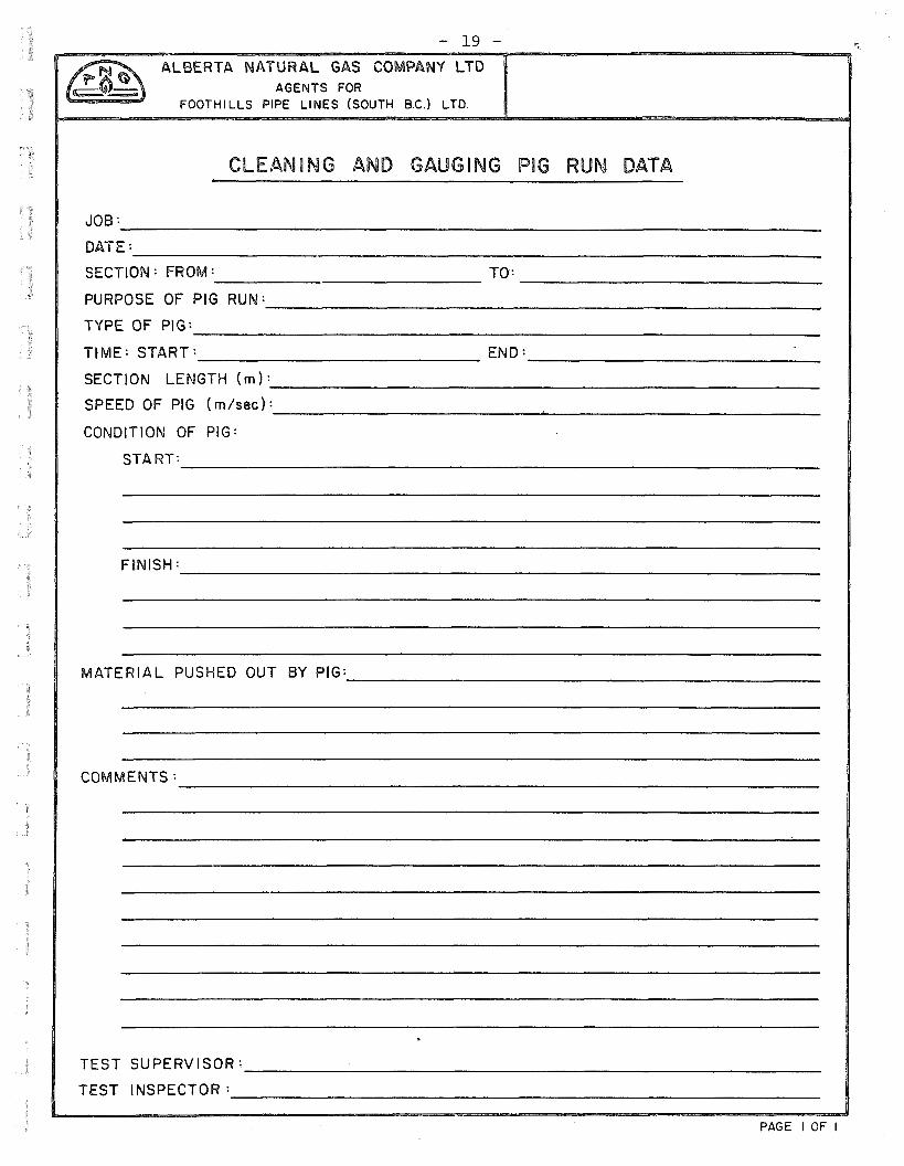
l) Cleaning and Gauging Pig Run Data
CONTRACTOR will complete this form whenever a
cleaning or gauging operation is performed on a test
section. MANAGER's inspector and CONTRACTOH's test
supervisor will sign the form and keep copies. The
original will be delivered to MANAGER.
2) Displacement Pig Run Data
CONTRACTOR will complete this form whenever a
displacement operation is performed on a test
section. MANAGER.' s inspector and CONTRACTOR's test
supervisor will sign the form and keep copies. The
original will be delivered to ~~NAGER.

-15-
3) Daily Testing Report
CONTRACTOR will prepare a daily testing report for
each day any test operation is being conducted. The
test data compiled on this report will be a brief
resume of all tests being conducted on the System,
including:
a) acceptance or rejection of tests completed this
date.
b) progress status of tests underway.
c) a description providing a documental record of
any other events that occurred during testing
operations.
The CONTRACTOR's test supervisor and MANAGER's
inspector will sign this form. The original will be
delivered to MANAGER.
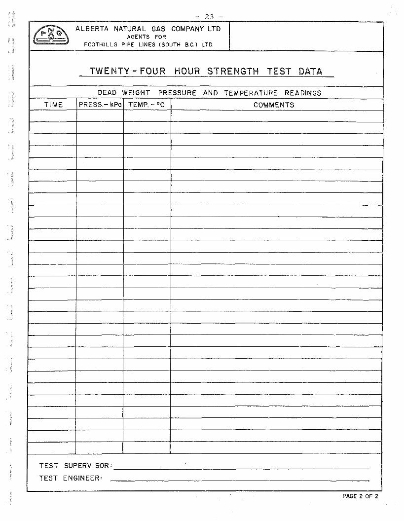
4) Twenty-Four Hour Strength Test Data
CONTRACTOR will complete this form for each 24 hour
strength test which must be performed on every test
section. Sufficient data and supplementary remarks
shall be recorded to adequately provide for
determination of acceptance or rejection of the test.
When the test is successfully completed, the report
will be signed by the CONTRACTOR's test supervisor
and MANAGER's engineer and will be initialled by the
National Energy Board's authorized representative.
The original will, be delivered to MANAGER along with
originals of the pressure and temperature recorder
charts.

-16-
5) Pipe Failure Report
CONTRACTOR will prepare this form for each failure
that occurs during the testing operations on the
System. The information recorded on this form will
provide a complete record of test conditions at the
time of failure and a detailed description of rcum
stances surrounding the failure to allow a careful
analysis in determining the cause of failure. This
form will furnish the basis for claims in case of
defective workmanship or materials. Photographs of
the failure will be taken and included with the
report. CONTRACTOR 1 s test supervisor and MANAGER 1 s
engineer will sign this form. The original will be
delivered to MANAGER.
FINAL TEST REPORT
At completion of testing operations, CONTRACTOR will
prepare a testing summary report which will be submittted
with all test files to I'1A.NAGER.
During the testing operation, the original test forms
with all signatures, pressure and temperature recorder
charts and record photographs will be transferred, after
reviewing, checking and signing, to ~~NAGER. At the
completion of the job, all other copies of the test
reports will be transferred to MANAGER.
SAMPLE TEST FORMS
Sample copies of test forms, which will be made available
to CONTRACTOR upon request during testing operations, are
included in Appendix III of this manual.

A P P E N D I X I
PIPE SPECIFICATIONS
AND TEST PRESSURES
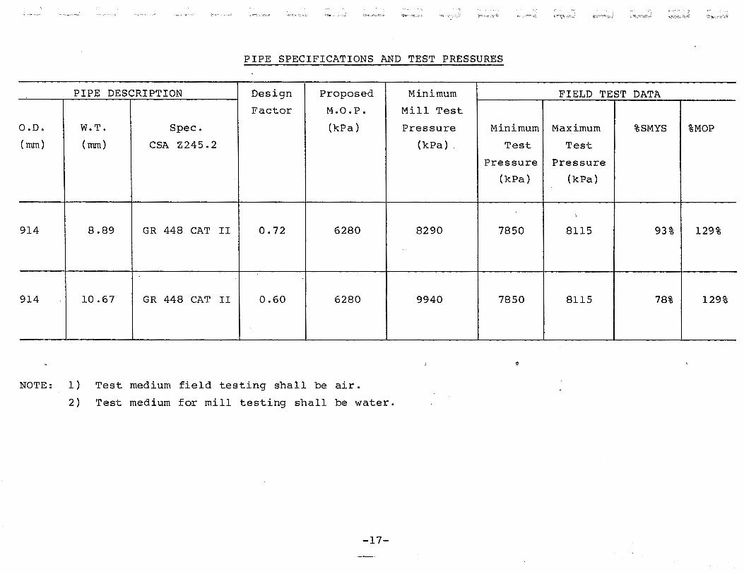
PIPE SPECIFICATIONS AND TEST PRESSURES
PIPE DESCRIPTION Design Proposed Minimum FIELD TEST DATA
Factor M.O.P. Mill Test
O.D. W.T. Spec. (kPa) Pressure Minimum Maximum %SMYS %MOP
(mm) (mm) CSA Z245. 2 (kPa) . Test Test
Pressure Pressure
(kPa) (kPa)
'
914 8.89 GR 448 CAT II 0.72 6280 8290 7850 8115 93% 129%
914 10.67 GR 448 CAT II 0.60 6280 9940 7850 8115 78% 129%
NOTE: 1) Test medium field testing shall be air.
2) Test medium for mill testing shall be water.
-17-

A P P E N D I X II
'rEST SECTIONS
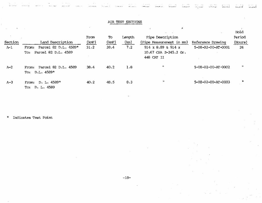
AIR TEST SECTIONS
li>
Hold Fran To Length Pipe Description Period
Section Land Description (kmP) (kmP) (krn) (Pipe Measurement in rrm) Reference Drawing (Hours) A-1 Fran: Parcel 82 D.L. 4589* 31.2 38.4 7.2 914 X 8.89 & 914 X 5-08-02-00-~-0001 24
To: Parcel 82 D.L. 4589 10.67 CSA z-245.2 Gr. 448 CAT II
A-2 Fran: Parcel 82 D.L. 4589 38.4 40.2 1.8 It 5-08-02-00-~-0002 " To: D.L. 4589*
A-3 From: D. L. 4589* 40.2 48.5 8.3 It 5-08-02-QQ-~-0003 It
To: D. L. 4589
* Indicates Test Point
-18-
A P P E N D I X I I I
TEST FORMS
- 19 -
@ ALBERTA NATURAL GAS COMPANY LTD AGENTS FOR
FOOTHILLS PIPE LINES (SOUTH B.C.) LTD.
CLEANING AND GAUGING PIG RUN DATA
JOB:
DATE:
SECTION : FROM : TO:
PURPOSE OF PIG RUN:
TYPE OF PIG:
TIME: START: END:
SECTION LENGTH(m):
SPEED OF PIG (m/sec):
CONDITION OF PIG:
START:
FINISH:
MATERIAL PUSHED OUT BY PIG:
COMMENTS:
. TEST SUPERVISOR:
TEST INSPECTOR:
PAGE I OF I

- 20 -
tE~ ALBERTA NATURAL GAS COMPANY LTD
AGENTS FOR FOOTHILLS PIPE LINES (SOUTH B.C.) LTD.
DISPLACEMENT PIG RUN DATA
JOB:
DATE:
TEST SECTION NO.:
PURPOSE OF PIG RUN:
TYPE OF PIG:
TIME: START: END:
SECTION LENGTH (m):
SPEED OF PIG ( m/sec.)
CONDITION OF PIG:
START:
FINISH:
COMMENTS:
·-
TEST SUPERVISOR: .
TEST INSPECTOR:
PAGE I OF I

- 21 -
~~ ALBERTA NATURAL GAS COMPANY LTD
AGENTS FOR FOOTHILLS PIPE LINES (SOUTH B.C.) LTD.
DAILY TESTING REPORT
JOB:
DATE:
WEATHER CONDITIONS:
TEMPERATURE (°C): HIGH: LOW:
REFERENCE TEST FORMS=
REPORT:
TEST SUPERVISOR: .
TEST INSPECTOR:
PAGE I OFI

- 22 -
tf~ ALBERTA NATURAL GAS COMPANY LTD AGENTS FOR
FOOTHILLS PIPE LINES (SOUTH B.C.) LTD.
TWENTY- FOUR HOUR STRENGTH TEST DATA
JOB=
DATE:
TEST SECTION NO.:
HYDROSTATIC TEST DRAWING NO.:
TIME WHEN YIELD TEST OR PLOT WAS COMPLETED:
TIME WHEN PUMP WAS DISCONNECTED: -
PRESSURE WHEN YIELD TEST OR PLOT WAS COMPLETED=
TEMPERATURE ( °C): START: FINISH:
DEAD WEIGHT PRESSURE AND TEMPERATURE READINGS
TIME PRESS.-kPa TEMP.- oc COMMENTS
l .
PAGE I OF 2
- 23 -
~ ALBERTA NATURAL GAS COMPANY LTD
AGENTS FOR FOOTHILLS PIPE LINES (SOUTH B.C.) LTD.
TWENTY- FOUR HOUR STRENGTH TEST DATA
DEAD WEIGHT PRESSURE AND TEMPERATURE READINGS
TIME PRESS.- kPo TEMP.- °C COMMENTS
TEST SUPERVISOR: .
TEST ENGINEER:
PAGE 2 OF 2

- 24 -
~ ALBERTA NATURAL GAS COMPANY LTD ~ AGENTS FOR
FOOTHILLS PIPE LINES (SOUTH B.C.) LTD.
PIPE FAILURE REPORT
JOB=--------------------------------------------------------------DATE= ____________________________________________________________ _
TEST SECTION N 0.: --------------------------------------------------TIME OF FAILURE=--------------------------------------------------LOCATION OF FAILURE=----------------------------------------------
ELEVATION AT FAILURE: --------------------------------------------PRESSURE AT FAILURE=----------------------------------------------FA I LED PIPE DATA --------------- mm 0. D. x ---------------- m m W. T.
GRADE= SPEC·~·-------------------------MFG. BY: JOINT NO. : ----------------------
REPLACEMENT PIPE DATA mm O.D. x --------- mm W.T.
GRADE: SPEC=----------------------MFG. BY: JOINT NO.:----------------DATE REPAIRED: ____________________________________________ ___
POSITION AND SIZE OF FAILURE:
B D
NOTE POSITION OF FAILURE AND DIMENSIONS:
A =------------- mm B: --------------- mm C: mm D: mm ---------------------
.DESCRIPTION AND POSSIBLE CAUSE OF FAILURE= ___________________ _
DAMAGES OR INJURIES=------------------------------------------
TEST SUPERVISOR=-----------------------------------------------TEST ENGINEER=
PAGE l OF l
A P P E N D I X I V
TEST INSTRUMENTS

ITEM
l
2
3
-25-
TEST INSTRUMENTS
All instruments being used in the test shall have been
properly calibrated before the test to ensure accurate
results. CONTRACTOR shall have personnel at test site who
are capable of operating, maintaining and calibrating the
instruments being used for the test. Test instruments, as
listed below, shall be furnished by CONTRACTOR. Quantities
shown are the minimum for one test crew. If multiple crews
are required to avoid delays, each test crew shall be
equipped with the instruments listed below:
QUANTITY
2
2
4
DESCRIPTION
Deadweight type pressure gauge having a useful range
of 0-15,000 kPa and an accuracy of + 1.0 kPa. One
gauge is to be available at the test site as a backup
unit.
Chart type pressure recorder utilizing 24 hour
circular charts and a useful range from 0-15,000 kPa.
The charts must have a maximum increment size of 200
kPa. One pressure recorder is to be available at the
test site as a backup unit.
Chart type temperature recorders utilizing 24 hour
circular charts and a useful range from -5°C to 40°C.
The charts must have a maximum increment size of l°C.
One temperature recorder is to be available at the
test site as a backup unit.

ITEr-1 QUANTITY
4 2
5 4
-26-
DESCRIPTION
Thermometer, -40 to 100°C range, accurate and
readable to at least l/2°C.
Gauge, pressure 0 to 16,000 kPa range, 4 1/2" dial,
1/2" NPT lower connection.

A P P E N D I X V
PIG RUN SEQUENCE
RUN
1
2
-27-
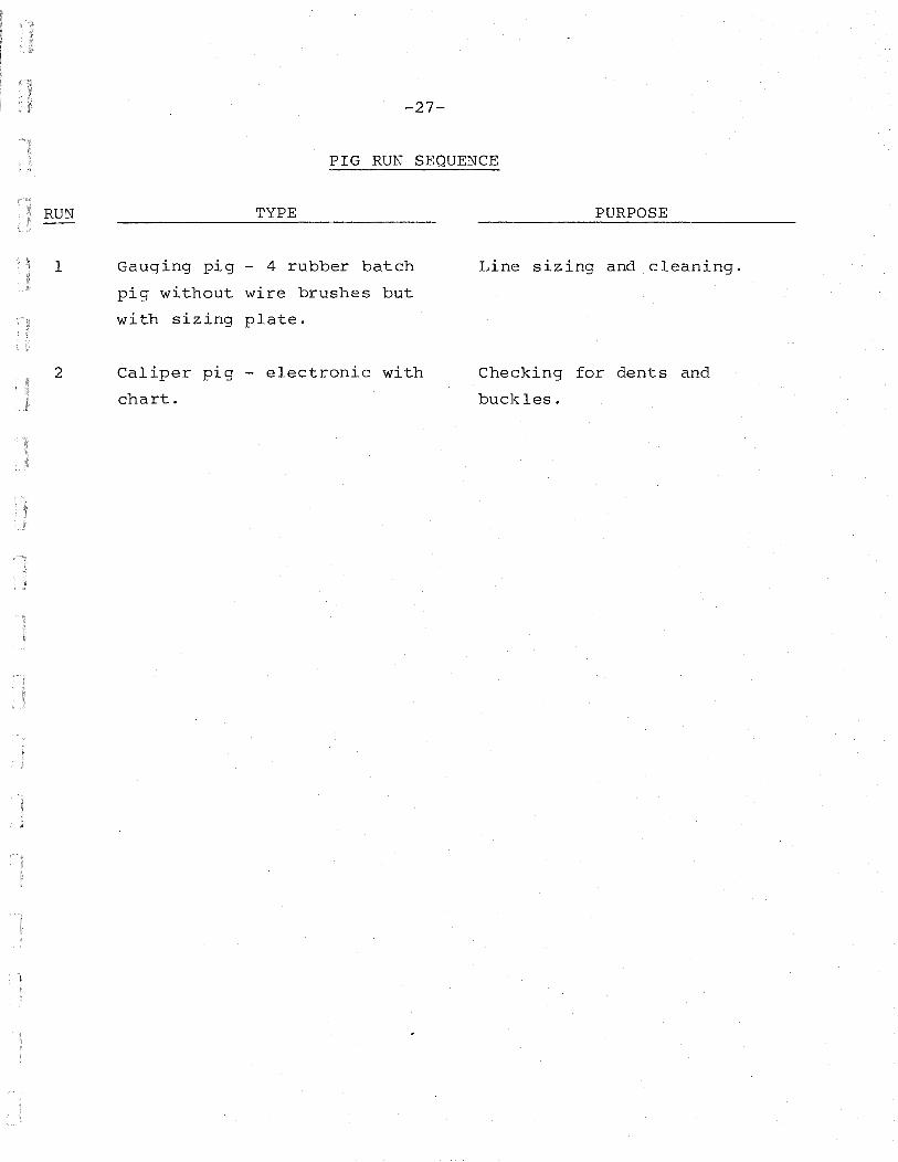
PIG RUN SEQUENCE
TYPE
Gauging pig - 4 rubber batch
pig without wire brushes but
with sizing plate.
Caliper pig - electronic with
chart.
PURPOSE
Line sizing and cleaning.
Checking for dents and
buckles.

DRAWINGS

DRAWING NUMBER
AIR TEST DRAWINGS
5-08-02-00-AT-0001
5-08-02-00-AT-0002
5-08-02-00-AT-0003
5-08-02-00-TP-0025
5-08-02-00-EN-0003
5-08-02-00-EN-0004
----------------~-~~·
-28-
DRAWINGS
TITLE
ALASKA HIGHWAY GAS PIPELINE PROJECT 914 mm O.D. GAS PIPELINE
Air Test Section A-1 Sta. 30+ 660 to 37+754.1
Air Test Section A-2 Sta. 37+ 754.1 to 39+412
Air Test Section A-3 Sta. 39+ 412 to 47+850.4
Typical Hydrostatic Test Warning Sign
914 mm Hydrostatic Test Head MOP 9590 kPa
914 mm Hydrostatic Test Head Bracket Details


·········-----------------------------------,-------.------------,
I .
I r----~ --- --- __________ , __ ! !
-ELEVATION IN METRES
ABOVE SEA LEVEL
§ + ~
TEST HEAD. SEE DWG
0 0
"' + fli
0
8 +
"' "'
0 0
"' + aJ
""
8 0 + m
"'
5-08 -02-00-EN -0(.{)3 --·--------------------1--------------------t-
~--- -- ________ L f-C..T.::E::.S.:.T..cS::-E'-'C-_T-:I::.O.::N,.:.T'='E S T PO I NT
ELEVATION 1814 0 m
~--------- ·---------TEST SECTION HIGH POINT TEST SECTION LC·\~EPOINT !
j-=E.::LccEV'-A_T_I::.O.cN ___ ...j-' , ' 4 0 m
LT.::E:::ST.:..:._P.::R.::E:::SS:::U':"R'."E=-L'n 8 9 k Po 7850kPo
ELEVATION 1954 0 m
'TEST PRESSURE TEST PRESSURE 7989 kPo
0 0
"' + "' "'
. . . . t . . -+--1
- -- j
- - ~
·TEST HEAD, SEE DWG 5·08·02 ·OO·EN-0003
i I
• • •
. ! . . .. . !
i : j - ----- ~------.--l
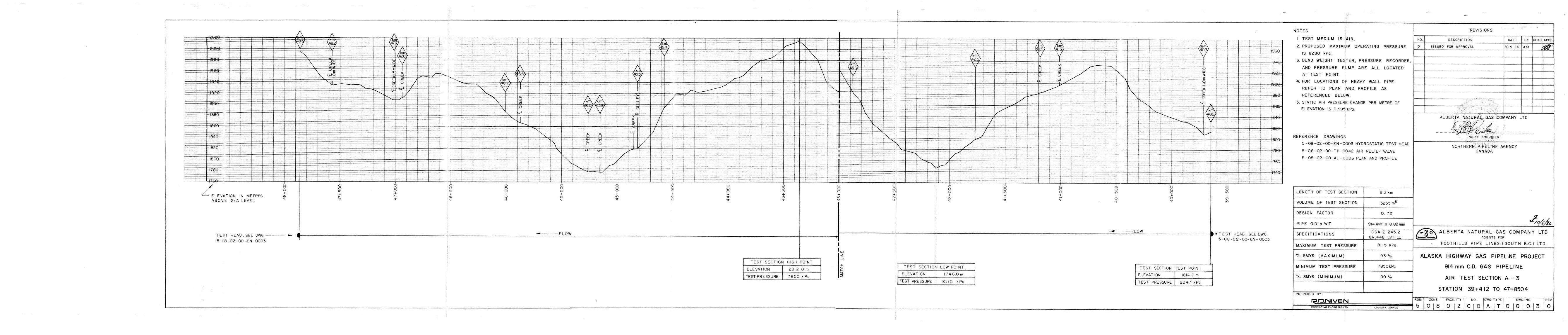
NOTES
L TEST MEDIUM IS AIR.
2. PROPOSED MAXIMUM OPERATING PRESSURE
IS 6280 kPa,
3. DEAD WEIGHT TESTER, PRESSURE RECORDER,
AND PRESSURE PUMP ARE ALL LOCATED
AT TEST POl NT.
4. FOR LOCATIONS OF HEAVY, WALL PIPE
REFER TO PLAN AND PROFILE AS
REFERENCED BELOW.
5. STATIC AIR PRESSU~E CHANGE PER METRE OF
ELEVATION IS 0.995 kPa.
REFERENCE DRAWINGS
5 ·08-02-00-EN -0003 HYDROSTATIC TEST HEAD
5·08-02-00-TP·D042 AIR RELIEF VALVE
5·08-02-00·AL-0005 PLAN AND PROFILE
5 ·08 ·02·00-AL ·0006 PLAN AND PROFILE
LENGTH OF TEST SECTION 1.8 km
VOLUME OF TEST S':CTION 1135 m3
DESIGN FACTOR 0 72
PIPE O.D, < W,T. 914 mm x. 8 .89mm
REVISIONS
NO. DESCRIPTION DATE BY
0 ISSUED FOR APPROVAL
~~------------
' /
ALB~~G,AS COMPANY LTD
~ - - J:s. ( .- ::_ ~ ....., .- - ~ - - - - - - - - -' ' .. , ' ' ::,. '\,_'-t:HIEf ENGINEER '< ~>-~ ..
NOR.TH(~ti:PIPELINE AGENCY 'CANADA
SPECIFICATIONS CSA Z 245.2 ~ALBERTA NATURAL GAS COMPANY LTD f--------------+--"G"-'R~.4::.4cc8e_:C,A::Tc..=II.__-i ~ AGENTS FOR
MAXIMUM TEST PR E:_'S~S:':'U~R_!OE_.j_ _ _'_79~8:'_9~k~P~a __ _j[-----F_O_O_T_H_I_L_L_S_P_I_P_E_L_I_N_E_S_.:.(_S_O_U_T_H_B_. c_.:..) _L_T_D_.___,
% SMYS (MAXIMUM) 91.6kPo
MINIMUM TEST PRESSURE 7850kPa
% SMYS (MINIMUM)
PREPARED BY:
.r:::J.NIVE N CONSULTING ENGINEER•; LTD CALGARY CANAOA
ALASKA HIGHWAY GAS PIPELINE PROJECT
914 mm 0.0. GAS PIPELINE
AIR TEST SECTION A -2
STATION 37+754.1 TO 39+ 412
RGN. ZONE FACILITY NO OWG. TYPE OWG. NO REV_
5 0 2 0

. I i:'
DRILL 2Z.23mm DIA ... tiOLES - ~~,-----,F""o''"R -~~fos 1mm BOLTS ·I I· 89
r.t- -t - - - - - - -~ - -_ N - - ~~r::_:_~-- -----~t _J._
NOTES
LUG DETAIL SCALE I ,z
I MATERIAL !N BiLL OF MATERIALS IS LISTED FOR TWO COMPLETE LiFTING BRACKEtS (TWO (2) BRACKETS REQUIRED PER TEST HEAD)
2. ALL DIMENSiONS ARE IN MILLIMFTRES 3 ENTIRE BRACKET ASSEMBLY TO BE FABRICATED USiNG FULL LENGTH 6.0mm FILLET WELDS
ON ALL SIDES. !
4. S.EE DRAWING 5-08-02-00-EN-0002 AND 5-08·02-00-£N .. 0003 "'OR 914mm TEST HEAD DETAILS
5 A''TER FABRiCATiON THE ENTIRE ASSEMBLY SHALL BE PAINTED SILVER WITH A RUSlf PREVENTATIVE PAINT 6. ADJUST THE DISTANCE BETWEEN BRACKETS AND CABLE LENGTH FOR LIFTING HEIGhT AFTER FABRICATION. T BRACKETS SHALL BE FABRICATED TO FIT SECURELY AROUND THE CIRCUMFERENCE OF 11HE TEST HEAD.
1
'
BRACKET DETAILS SCALE I .10
. .. ·
3.0rnm SHIM (REMOVE AFTER FAB)
/
/
RI:"V
SLING DETAIL SCAt.£ 1•10
' f--"·"""- ······- ---- ...
::lfSCRI?T>ON
64 ... + 64 ... .,..j
PLATE DETAIL SCALE 1. 3
REVISIONS
1 '
I OA1E I BY CHIW APPR
idbt 1------t-~~-··············-------------t---··' ····---1--l
J----t-··--·-······-· ---·-····-f---· ' :-+----l I , t
~·,____; ~--~-------~- ...... __ -- -r- i r----·r·-··-----------··· ···-···----- +---+:-+-~. -t---1 c-----r------.,-, ----+--t;--1:~-+ -
.......... . ____ ........ ------~-r----1-r--·----f---~if----1 :
ALBERTA NATURAL GAS COMPANY LTD
CHIEF ENGINEER
.
••
ITEM
2
3
4
5
6
7
8
9
10
I I
12
MATERIAL LIST
DESCRIPTION QTY UNIT 1---:,.,-'f''"'. O~. -,-=;-rl NO. ITEM
FLAT BAR, 89mm X 12.7mm THICK, M.S ,ASTM A -36
8 m SUPPLIED BY SHOP
76mm CHANNEL AT 7.44 kg/m ASTM A-36. 9.4 m
PLATE,304.8mmX203.2mmXI9.05mrnTHICK l EAC!- " MS, ASTM A-36.
FLAT BAR, 152.4mm X 6.35mm THICK, M.S. ASTM 5. 2 m
A ·36
LUG,I14.3mmX76.2mmXI2.7mmTHICK,M.S., 2 EACH ASTM A-36.
19.05mm DIA.QRDINARY LAY WIRE CORE ROPE 6.2 m
6 X 26
1905mm THICK THIMBLE,EX. HVY, 'CROSBY- 4 I£ACH LAUGHLIN' G -414.
19.05mm CROSBY CLIPS. 16 EACH
i9.05mm GALVANIZED ROUND PIN ANCHOR SHACKLE 2 EACH
i9.05mm DIA. BOl,.T, A· 307, C/W NUTS 8o WASHERS. 2 I£ACH
19.05 mm CHAIN BBB, TRADE I . 3 m
BOLT, 19.05mmDIA.X51.4mmLONG,A-307,C/W 8 EACH
NUTS 8. WASHERS
NORTHERN PIPELINE AGENCY CANADA ~ALBERTA NATUR.~~,?~~ COMPANY LTD
FOOTHILLS PIPE LINES (SOUTH BC) LTD
914mm HYDROSTATIC TEST HEAD
BRACKET DETAILS r----- ····"·-~-- ............. -------·······-·-·""·------;
SGAL f. AS SHOWN i RGN zo-~iE T:·r-;:c.-.c~l:... ---r NO DWG TYPE DRAWING NO I :=;-f\'
5 0 1 8;012 0,0 E 1 N 0 1 0,0 4j0
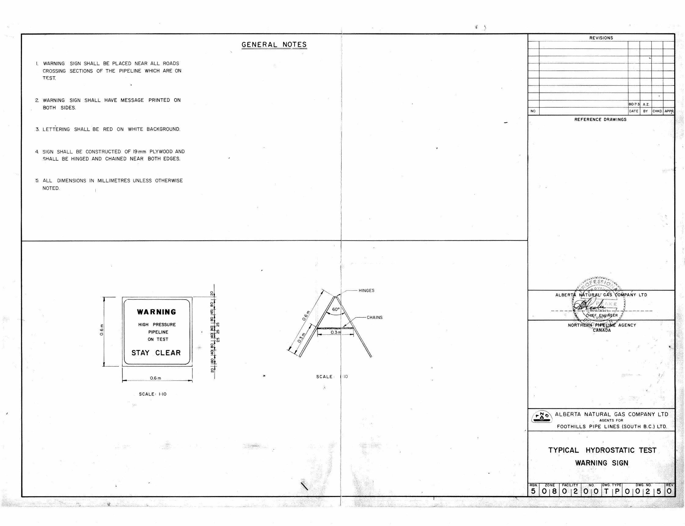
I. WARNING SIGN SHALL BE PLACED NEAR ALL ROADS
CROSSING SECTIONS OF THE PIPELINE WHICH ARE ON
TEST
2. WARNING SIGN SHALL HAVE MESSAGE PRINTED ON
BOTH SIDES.
' 3. LETTERING SHALL BE RED ON WHITE BACKGROUND.
4. SIGN SHALL BE CONSTRUCTED OF 19 mm PLYWOOD AND
SHALL BE HINGED AND CHAINED NEAR BOTH EDGES.
5. ALL DIMENSIONS IN MILLIMETRES UNLESS OTHERWISE
NOTED.
WARNING
E HIGH PRESSURE I.D
PIPELINE 0 ON TEST
STAY CLEAR \.
L 0.6m
SCALE: 1:10
··.··•·
GENERAL NOTES
0 C\1
-0 a:>
iO !:.. 0 0)
- I()
~ C\1
I ~ ~
I() - C\1 0 0)
~ 0 ~ ~ -
I 0 C\1
I
,_,.,,_ c --\j:(
~·· .. ··
·'· ......
..... ···.
i.
REVISIONS
80·7·3 A.Z.
NO DATE BY CHKO. APPR '
REFERENCE DRAWINGS
I
SCALE = 10
/;.Th ALBERTA NATURAL GAS ( _r , AGENTS FOR
FOOTHILLS PIPE LINES (SOUTH B.C.) LTD.
COMPANY LTD <,~ I fi·
·< L
'r---~----------------------------------~
TYPICAL HYDROSTATIC TEST ·
WARNING SIGN .
RGN. ZONE FACILITY NO. DWG. TYPE c . ·' :</ .•· ..
·:; •.• .,. I ' I •·. ... <<i) .•. .. '· .. .,·