AIR RESOURCES BOARD FIELD EVALUATION OF HEAVY-DUTY …
214
AIR RESOURCES BOARD FIELD EVALUATION OF HEAVY-DUTY DIESEL NOx CONTROL STRATEGIES January 2013 This report has been reviewed by the staff of the California Air Resources Board and approved for publication. Approval does not signify that the contents necessarily reflect the views and policies of the Air Resources Board, nor does mention of trade names or commercial products constitute endorsement or recommendation for use.
Transcript of AIR RESOURCES BOARD FIELD EVALUATION OF HEAVY-DUTY …

AIR RESOURCES BOARD
FIELD EVALUATION OF HEAVY-DUTY DIESEL NOx
CONTROL STRATEGIES
January 2013
This report has been reviewed by the staff of the California Air Resources Board and approved for publication. Approval does not signify that the contents necessarily reflect the views and policies of the Air Resources Board, nor does mention of trade names or commercial products constitute endorsement or recommendation for use.

Table of Contents
EXECUTIVE SUMMARY ....................................................................................................................................... i i. Background ...................................................................................................................................................i ii. New Study “Field Evaluation of Heavy-Duty Diesel NOx Control Strategies”.......................................... iv iii. Conclusion ................................................................................................................................................. xii
I. Introduction ................................................................................................................................................. 1 II. Investigation Plan ....................................................................................................................................... 3
III. DEF Availability Survey .............................................................................................................................. 4 A. CONCLUSION ................................................................................................................................................ 7
IV. DEF Quality Tampering Survey ................................................................................................................. 8 A. DEF QUALITY ANALYSIS ........................................................................................................................... 10 B. CONCLUSION .............................................................................................................................................. 11
V. Re-Evaluation of Driver Inducements on Two SCR Equipped 2010 Model Year Cummins Engines 13 A. TEST VEHICLE 1 ......................................................................................................................................... 21 B. TEST VEHICLE 2 ......................................................................................................................................... 36
VI. Continued Evaluation of 2010+ NOx Control Strategies ....................................................................... 57 A. TEST VEHICLE 3 ......................................................................................................................................... 60 B. TEST VEHICLE 4 ......................................................................................................................................... 89 C. TEST VEHICLE 5 ....................................................................................................................................... 119 D. EMISSION EVALUATION OF NOX CONTROL STRATEGIES ......................................................................... 133
VII. Overall Conclusions ............................................................................................................................... 135
VIII. Appendices .............................................................................................................................................. 139
A. Appendix A - DEF Availability Survey
B. Appendix B - SCR / DEF Tamper Survey
C. Appendix C - Test Plan 2R1102
D. Appendix D - Test Plan 1Q1102

i.
EXECUTIVE SUMMARY
i. Background
The California Air Resources Board (ARB) and the United States Environmental Protection Agency (U.S. EPA) adopted a 0.20 gram per brake horsepower-hour (g/bhp-hr) oxides of nitrogen (NOx) emission standard for heavy-duty diesel (HDD) engines beginning with the 2010 model year (MY). The majority of engine manufacturers chose selective catalytic reduction (SCR) technology to attain this standard. All engines equipped with SCR use a liquid urea solution as the reductant, known commonly as diesel exhaust fluid (DEF). Using DEF increases the operational cost to truck operators, theoretically creating an incentive for operators to find ways to circumvent the SCR system and reduce costs by minimizing DEF usage. This could occur if DEF is not replenished with another fluid such as water, or if the DEF delivery system is disabled.
Over the past several years, industry met with ARB and the U.S. EPA to discuss strategies to assure that DEF is used properly and improper maintenance and tampering by truck operators is minimized. The U.S. EPA published guidance documents in the 2007 calendar year, in February 2009 (referred to as 2009 U.S. EPA Guidance) and again in December of 2009 (U.S. EPA reference numbers CISD-07-07 dated March 27, 2007, CISD-09-04 dated February 18, 2009 and CISD-09-04 REVISED dated December 30, 2009) to inform engine manufacturers of the steps they should take to assure DEF is used and mal-maintenance and tampering are minimized. While the guidance documents were not considered policy by the ARB, ARB provided comments during the development of the February 2009 U.S. EPA Guidance (referred to hereafter as “2010 MY Guidance”) and during its 2010 engine certification reviews for California.
The 2010 MY Guidance document provided advisory information that addressed how manufacturers of SCR-equipped engines should incorporate driver warning systems, driver inducement strategies, identification of incorrect reducing agents, tamper resistant designs, and freeze protection. In addition, as a condition of certification, ARB requires manufacturers to demonstrate that all emission control systems are tamper resistant. In the case of SCR, which requires the routine addition of DEF, most manufacturers utilized driver inducements to demonstrate tamper resistance when certifying their vehicles. Consistent with the 2010 MY Guidance, these inducements first alert the driver that the DEF supply is low, and are subsequently followed by a reduction in truck performance or other inducements to encourage the driver to refill the DEF supply. Ultimately, if DEF is not refilled, or if an inappropriate fluid is added, or if hardware is tampered, the vehicle is immobilized by the engine control system. The ARB and U.S. EPA held a joint workshop in July of 2010 to update the SCR inducement strategy guidelines (referred to hereafter as “2011+ MY Guidelines”) to be applied during the 2011 MY certification process. The 2010 MY Guidance and July 2010 ARB and U.S. EPA SCR Workshop expectations are outlined in the following table:

ii.
SCR Guidance and Workshop Guideline Summary
During the July 2010 SCR Workshop, Navistar, the one manufacturer that was not using SCR, raised concerns about the use of SCR to comply with the 2010 standards. Navistar claimed, based on their own test program that the driver SCR warning alerts and engine inducements used for the 2010 MY engines were not effective in deterring

iii.
drivers from not refilling DEF or otherwise tampering with the DEF dispensing system, and that SCR was not an effective emission control strategy. (Navistar recently announced it will use SCR on most of its future engines.) In response to the expressed concerns of DEF availability, SCR tampering, and effectiveness of SCR inducement strategies, ARB initiated field investigations in 2010 to evaluate the first year implementation of SCR for the 2010 MY HDD vehicles. The investigation included:
(1) Two surveys of DEF availability within the State of California;
(2) A survey to determine whether truck operators driving 2010 MY SCR-equipped trucks on California roadways have tampered with SCR components or are not using DEF;
(3) An examination of the types and effectiveness of SCR driver inducements employed on 2010 MY HDD vehicles; and
(4) An examination of the emission impacts of HDD SCR-equipped vehicles when DEF has been depleted, diluted or the SCR system has been tampered.
The findings of this study were published in a May 2011 report entitled, “Heavy-Duty Vehicle Selective Catalytic Reduction Technology Field Evaluation” (May 2011 Report - http://www.arb.ca.gov/msprog/cihd/resources/reports/scrreport.pdf) and are summarized below:
(1) The results of the two DEF availability surveys indicated that DEF was readily available in 2010 at major diesel truck stop refueling stations, 85% and 92% respectively. In addition, both surveys indicated that 30% of retailers that normally supply parts and equipment for light-, medium-, and HDD vehicles and trucks had DEF available.
(2) Roadside inspections of 69 SCR-equipped trucks showed that all of the trucks were using proper DEF solution, no tampering was present, and no DEF-warning lights or audible alerts had been initiated. Sixty of the 69 drivers had no problem locating DEF while the remaining nine drivers indicated some problems locating DEF. However, 68 of the drivers said they never ran out of DEF while operating their vehicles and one indicated he drove only 10 miles with an empty DEF driver’s gauge reading.
(3) Three 2010 MY engines (Cummins 6.7L, 14.9L, and a DDC 12.8L) were tested to evaluate how SCR inducement strategies functioned under three different scenarios: (a) when DEF is depleted under normal driving (DEF Depletion Cycle); (b) when DEF is replaced with water (DEF Contamination Cycle); and (c) when an SCR component is tampered to cause DEF to stop dosing (DEF System Tampering Cycle). The test program evaluation showed that driver inducements occurred for each vehicle based on the three SCR related inducement cycles mentioned above. There were individual vehicle issues on the Cummins’ engines where the 6.7L engine experienced a problem with the DEF heater system that caused the DEF system to overheat
iv.
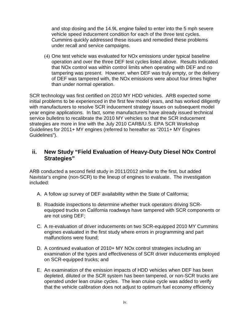
and stop dosing and the 14.9L engine failed to enter into the 5 mph severe vehicle speed inducement condition for each of the three test cycles. Cummins quickly addressed these issues and remedied these problems under recall and service campaigns.
(4) One test vehicle was evaluated for NOx emissions under typical baseline operation and over the three DEF test cycles listed above. Results indicated that NOx control was within control limits when operating with DEF and no tampering was present. However, when DEF was truly empty, or the delivery of DEF was tampered with, the NOx emissions were about four times higher than under normal operation.
SCR technology was first certified on 2010 MY HDD vehicles. ARB expected some initial problems to be experienced in the first few model years, and has worked diligently with manufacturers to resolve SCR inducement strategy issues on subsequent model year engine applications. In fact, some manufacturers have already issued technical service bulletins to recalibrate the 2010 MY vehicles so that the SCR inducement strategies are more in line with the July 2010 CARB/U.S. EPA SCR Workshop Guidelines for 2011+ MY engines (referred to hereafter as “2011+ MY Engines Guidelines”).
ii. New Study “Field Evaluation of Heavy-Duty Diesel NOx Control Strategies”
ARB conducted a second field study in 2011/2012 similar to the first, but added Navistar’s engine (non-SCR) to the lineup of engines to evaluate. The investigation included:
A. A follow up survey of DEF availability within the State of California;
B. Roadside inspections to determine whether truck operators driving SCR-equipped trucks on California roadways have tampered with SCR components or are not using DEF;
C. A re-evaluation of driver inducements on two SCR-equipped 2010 MY Cummins engines evaluated in the first study where errors in programming and part malfunctions were found;
D. A continued evaluation of 2010+ MY NOx control strategies including an examination of the types and effectiveness of SCR driver inducements employed on SCR-equipped trucks; and
E. An examination of the emission impacts of HDD vehicles when DEF has been depleted, diluted or the SCR system has been tampered, or non-SCR trucks are operated under lean cruise cycles. The lean cruise cycle was added to verify that the vehicle calibration does not adjust to optimum fuel economy efficiency

v.
settings while sacrificing NOx emissions when the vehicle is traveling at steady cruise speed conditions. All emissions were measured with a Portable Emissions Measurement System (i.e., a PEMS unit).
The results of the investigations are discussed below.
A. Summary of DEF Availability Survey
During the 2011 and 2012 calendar year, staff conducted field surveys and inspections similar to those performed in 2010. These surveys confirm that DEF has become readily available in California as DEF can now be purchased at the fuel pump at most major national truck stop fueling stations (100 percent availability of the 34 stations surveyed) and has become increasingly available at auto part retailers (90 percent availability of 79 retailers surveyed) and smaller independent HDD trucks stops (73 percent availability of 112 smaller stations surveyed). Overall, the results of the SCR surveys showed that DEF is widely and conveniently available in California.
B. Summary of DEF Quality and Tampering Survey
In regards to proper DEF usage, the ARB conducted a new survey of 243 SCR-equipped HDD trucks for DEF usage and tampering. The results of the survey were consistent with the 2010 audit showing no tampering of SCR systems and all 243 vehicles were using the proper DEF concentration. Overall, owners are on-board with providing the proper DEF concentrations for their vehicles.
C. Re-Evaluation of Driver Inducement on Two SCR-Equipped 2010 Model Year Cummins Engines (Test Vehicles 1 & 2)
In March 2011, ARB launched a test program to recheck the two Cummins 2010 MY engines that were tested in August 2010 (as mentioned in Section i(3) above) and as indicated have been corrected by Cummins.
Due to the voluntary recall and/or service campaigns that Cummins provided to their 2010 MY engine in use customers, staff expected some SCR inducement strategies may have been updated to be more consistent with the 2011+ MY Guidelines. The recalibrations were reported to update SCR related software including reduced time/mileage periods to more severe warnings and inducements, and/or additional safe harbor triggers.
The trucks were operated under similar test cycles as performed in 2010 (a) when DEF is depleted under normal driving (DEF Depletion Cycle); (b) when DEF is replaced with water (DEF Contamination Cycle); and (c) when an SCR component is tampered to cause DEF to stop dosing (DEF System Tampering Cycle).
ARB’s re-evaluation of the two Cummins SCR-equipped HDD vehicles demonstrated that the warnings and inducement strategies incorporated by the engine manufacturer

vi.
were consistent with the 2010 MY Guidance as certified and rectified the issues detected in the first round of testing. In addition, the service campaigns led to the vehicles’ SCR inducement management performance to be mostly consistent with the 2011+ MY engines. The issues for full consistency with the newer guidelines for 2011+ MY engines mainly dealt with timing concerns. Specifically, Test Vehicle 1 took approximately twice the suggested time as per the 2011+ MY Guidelines to search for a safe harbor event for the final inducement under the DEF Contamination and DEF System Tampering Cycles. Also, Test Vehicle 1 did not search for safe harbor event within 1 hour (this event took approximately 4 hours to accomplish) when a repeat tampering event was instituted on the vehicle (i.e., re-disconnecting the vehicle’s DEF doser injector after connecting it to clear a no start condition). In May 2011 Cummins launched a voluntary service campaign on their 2010 MY 6.7L engines to address the timing parameters to search for safe harbor event for DEF contamination, SCR tampering and SCR repeat offense events that are more consistent with the 2011+ MY Guidelines. Test Vehicle 2 almost doubled the one hour suggested 2011+ MY Guidelines for identifying contaminated DEF under the DEF Contamination Cycle and therefore was not fully consistent with the intended objectives of the 2011+ MY Guidelines. ARB staff is continuing to evaluate Cummins’ control logic for DEF contamination guidance consistency with the 2011+ MY Guidelines. The following table summarizes Test Vehicles 1 and 2’s performance with each of the test cycles evaluated and how each engine compared to the suggested guidance from the 2010 MY Guidance and the 2011+ MY Guidelines.

vii.
Test Vehicle Consistency With SCR Guidance
GUIDANCE TEST CYCLE
TEST VEHICLE
#1 Cummins
2010MY 6.7L
#2 Cummins
2010MY 14.9L COMMENTS
2010 MY Guidance
DEF Depletion Cycle YES YES
DEF Contamination Cycle YES YES
DEF System Tampering Cycle YES YES
2011+ MY Guidelines
DEF Depletion Cycle YES YES
DEF Contamination Cycle NO* NO**
* When conducting a contamination, tampering and a repeat offense event, the vehicle did not search for safe harbor within 4 hours after initiating the first driver warning (1 hour guidance for the repeat offense event). Chrysler Technical Service Bulletin (No. 18-029-11) corrected these issues. ** The DEF Contamination Cycle took approximately 2 hours (105 miles) to launch the first driver warning; outside of the one hour guidance.
DEF System Tampering Cycle NO* YES
* See explanation in the cell above.
In regards to the emission results for these vehicles, Test Vehicle 1 was not tested because emissions testing were reported on this vehicle in the previous report. Test Vehicle 2 performed as expected with the vehicle operating within its respective NOx Not-To-Exceed (NTE) standard under normal vehicle operation and under the DEF Depletion Cycle until DEF was fully depleted. Once DEF had completely depleted, the NOx emissions did increase but the driver was experiencing a significant engine power derate (approximately 40 percent less power) that would not be tolerated by any vehicle operator. The same power derate inducement conditions also occurred under the DEF Contamination and DEF System Tampering Cycles. The lack of power experienced under these test cycles with the subsequent 5 mph limited speed event will force the operator to have these issues remedied immediately.

viii.
D. Continued Evaluation of 2010+ MY NOx Control Strategies Staff evaluated three additional HDD vehicles. The vehicles were driven over prescribed driving routes to evaluate their NOx control systems and their response to improper DEF use and tampering. The vehicles evaluated included a 2012 MY Freightliner Cascadia truck equipped with a 2011 MY 12.8 liter Detroit Diesel Corporation (DDC) DD13 engine (Test Vehicle 3) using SCR after treatment, a 2011 MY Volvo truck equipped with a 2010 MY 12.8 liter Volvo D13H engine (Test Vehicle 4) using SCR after treatment, and a 2012 MY International truck equipped with a 12.4 liter Navistar Maxxforce 13 engine (Test Vehicle 5) with no SCR after treatment.
1. SCR-Equipped Engine Evaluation – DDC (Test Vehicle 3) and Volvo (Test Vehicle 4)
ARB decided to test two additional SCR-equipped engines that were expected to comply with the 2011+ MY Guidelines. Specifically, the two engines tested were the 2011 MY 12.8 liter Detroit Diesel DD13 and the 2010 MY 12.8 liter Volvo D13H engines. The Volvo’s 2010 MY engine had been updated with a SCR calibration similar, but not identical, to their 2011 MY SCR equipped engines; hence the Volvo’s 2010 MY engine was expected to be consistent with the 2011+ Guidelines. Staff ran a series of tests similar to the prior report (DEF Depletion, DEF Dilution, and DEF System Tampering Cycles) to determine if the SCR calibrations for these engines prompted driver warnings and vehicle inducements that were consistent with the vehicle owner’s manuals and the 2010 MY Guidance and 2011+ MY Guidelines. For these SCR equipped engines, typically, a sequence of visual and/or audible warnings on the instrument panel (e.g. warning lights, chimes, and/or text message displays) indicating that the DEF supply is low or a problem exists with the SCR system. As additional mileage is accumulated without remedying the problem or refilling the DEF supply, further driver inducements should occur, such as power de-rates or limited vehicle speed. Ultimately, if the problem is not corrected, a severe inducement or final immobilization in the form of a no-start condition, or 5 mph maximum speed limit, or idle-only operation should be triggered once the vehicle reaches a safe harbor (e.g. when refueling the vehicle, turning off the vehicle or idling the vehicle for an extended period of time). In addition to these test cycles, staff also ran a new cycle called the DEF Dilution Cycle. The purpose of this evaluation was to determine if the SCR system is capable of detecting a diluted DEF concentration as opposed to completely filling the DEF tank with water. Concurrently while running each test cycle, staff measured NOx emissions with a PEMS device by first establishing baseline NOx emissions for normal vehicle operation over a prescribed test route. Staff continued to measure NOx emissions for each of the SCR test cycles over the same prescribed test route to determine the effects each test cycle had on NOx emissions.

ix.
In testing the 2011 DDC engine, DDC was consistent with the 2011+ Guidelines with the exception of the DEF System Tampering Cycle. ARB staff observed that under the DEF System Tampering System Cycle, with the DEF doser injector disconnected, the vehicle did not begin its search for final inducement until well after four hours since the first driver alert occurred and therefore was not consistent with the intended objectives of the 2011+ MY Guidelines. DDC staff indicated that synergistic effects of their SCR calibration as operated under ARB’s prescribed driving cycle may have prevented a timely SCR inducement strategy from searching for a safe harbor event (i.e., ARB’s driving cycle did not encounter a transitional requirement like a refueling event or an extended idle time which is normal operation for these types of vehicles). ARB staff is continuing to evaluate DDC’s control logic for consistency with the 2011+ MY Guidelines. The Volvo evaluation results showed that this engine was consistent with the 2010 MY Guidance (for which this engine was certified) and the 2011+ MY Guidelines for all conducted test cycles. A summary for both the DDC and Volvo engines are shown below.
Test Vehicle Consistency With SCR Guidance
GUIDANCE TEST CYCLE
TEST VEHICLE
#3 DDC
2011MY 12.8L
#4 Volvo
2010MY 12.8L
COMMENTS
2010 MY Guidance
DEF Depletion Cycle NA1 YES
DEF Contamination Cycle NA1 YES
DEF System Tampering Cycle NA1 YES
DEF Dilution Cycle NA1 YES
2011+ MY Guidelines
DEF Depletion Cycle YES YES
DEF Contamination Cycle YES YES
DEF System Tampering Cycle NO*** YES
*** Under the DEF System Tampering Cycle the engine was not fully consistent with the intended objectives of the guidelines. .
DEF Dilution Cycle YES YES
1 – Test Vehicle 3 was a 2011 MY engine and was certified with respect to the 2010 CARB/U.S. EPA SCR Workshop Guidelines for 2011+MY. Therefore, the 2010 MY Guidance information does not apply to this engine.

x.
2. EGR-only Equipped Engine – Navistar (Test Vehicle 5)
Navistar 2011 MY 12.4L (Test Vehicle 5): Exhaust Gas Recirculation (EGR) equipped engine NOx control is achieved by recirculating a portion of the engine’s exhaust back into the engine’s air intake system. In the case of EGR only equipped engines (non-SCR), drivers may desire to achieve more power and/or fuel economy by turning off or otherwise tampering with the EGR system. Staff examined the vehicle owner’s manuals to determine the expected inducement strategies for each vehicle when tampering with the vehicle’s EGR system. Typically, this includes a visual warning on the instrument panel (e.g., a check engine light) indicating a problem with the engine. The test cycles performed on this vehicle included a Restricted EGR Cycle and a Lean Cruise Cycle. For the Restricted EGR Cycle staff placed an aluminum plate between the EGR cooler and the EGR transfer pipes to simulate the effects caused by a plugged EGR cooler or when an EGR valve became inoperable or stuck in the closed position. For the Lean Cruise Cycle staff drove the vehicle at steady speeds, which required minimal throttle movement, over a prescribed test route that was reasonably flat. A Lean Cruise Cycle was added to verify that the vehicle calibration does not adjust to optimum fuel economy efficiency settings while sacrificing excessive NOx emissions while a vehicle is operated at steady cruise speed conditions. This type of calibration is considered a defeat device that led to a consent decree with several heavy-duty engine manufacturers in the late nineties for unscrupulous business practices. This test cycle was performed to simply check that this engine did not have a calibration that would create better fuel economy but at the risk for creating an excessive NOx condition. Staff operated the vehicle over the same prescribed test route as the SCR-equipped engines and also equipped these vehicles with a PEMS unit to measure NOx emissions. Staff first established the baseline emissions under normal vehicle operation over the prescribed test route and then operated the vehicle under the Restricted EGR Cycle and Lean Cruise Cycle monitoring the NOx emissions created by these test cycles. When the Navistar 12.4L engine was performing under normal vehicle operation, the engine ran well and NOx emissions were within its applicable NOx standard (0.5 g/bhp-hr, which is higher than the other engines reported on). However, with the EGR disabled, the NOx emissions were 9.3 times above the limit, engine performance suffered, and the vehicle exhibited surging at the lower engine operating range. The driver commented that the problems created by this tampering event would not be tolerated because the surging condition and loss of power occurred at lower RPM’s where the engine would normally operate. Based on the results of this test cycle, staff ascertained that plugging the EGR will lead to driver warnings in the form of a MIL, poor drivability and reduced fuel economy (9 percent less fuel economy than normal operation). In regards to the Lean Cruise Cycle evaluation, the emission data from the Lean Cruise Cycle 2 evaluation showed that although the NOx emissions increased by almost nine percent with the cruise control set as compared to the baseline data;

xi.
however, the overall results whether the vehicle was operated in the baseline mode or with the cruise control set were both within the applicable NTE standard. Therefore, operating the vehicle in a steady cruise condition did not cause excessive NOx emissions under this mode of operation.
3. NOx Emissions Evaluation for Vehicles 3, 4, & 5 In order to compare the relative NOx control of the three trucks (DDC, Volvo and Navistar), staff operated them over the same designated test route three times each and measured their NOx emissions using a PEMS measurement device. The average baseline (no tampering of the SCR or EGR systems) NOx emissions were obtained for each truck and plotted for comparison. Overall, the NOx results for these vehicles performed very well with each vehicle meeting their respective NTE NOx emission standards. It should be noted that the DDC and Volvo trucks equipped with SCR technology are certified to the 0.2 g/bhp-hr NOx standard and the Navistar truck, that mainly utilizes EGR to control NOx (i.e., no SCR), is certified to the 0.5 g/bhp-hr NOx Family Emission Limit (FEL2). Intriguingly, the SCR-equipped engines are certified 2.5 times lower than the non-SCR Navistar engine which is the same difference when considering the baseline NOx emissions data (i.e., the SCR-equipped engines NOx levels were approximately 2.5 times lower than the non-SCR engine). This study clearly shows that the engines with SCR technology outperformed the EGR-only equipped engine for controlling NOx.
2 – Certification to the Family Emission Limit (FEL) is the emission level declared by the manufacturer and serves in lieu of an emission standard for certification purposes in any averaging, banking, or trading programs.

xii.
iii. Conclusion
The ARB has shown through various DEF availability surveys and DEF tampering inspections that DEF has become widely available in California and that the trucking industry is complying with the requirements to operate SCR-equipped vehicles on quality DEF. ARB’s evaluation of the four SCR-equipped HDD vehicles demonstrated that the warnings and inducement strategies incorporated on these engines were consistent with the vehicle manufacturers owner’s manuals, the 2010 MY Guidance and largely consistent with the 2011+ MY Guidelines.
The technology of today’s HDD engines does not lend itself to be tampered with and the advancement of SCR engines has shown that the engine’s management system will create intolerable engine inducement consequences when DEF is depleted to empty or the SCR system is tampered. In short, staff believes that companies and truck operators will simply not tamper with their HDD vehicle and risk costly repairs and/or possible fines especially when tampering or not using DEF will cause the engine’s power to degrade and ultimately lead to no-start conditions or severely limited speed. Engine manufacturers continue to work with ARB in improving their SCR inducement strategies for current model year engine certifications and in some cases have voluntarily incorporated software enhancements to upgrade their older SCR engine management strategies that are already in commerce.
ARB’s emissions testing from this evaluation demonstrated that the SCR-equipped engines when operating on quality DEF are meeting the HDD NOx NTE in-use emission requirements. Additionally, the non-SCR engine also met its NTE in-use emission standards; however, the NOx emissions from the non-SCR engine were significantly higher than the SCR-equipped engines because it is using emission credits to certify to a laxer standard.

1.
I. Introduction
In May 2011, the California Air Resources Board (ARB) published a document titled,
Heavy-Duty Vehicle NOx Control Strategies Technology Field Evaluation (May 2011
Report). The report discussed how most manufacturers are utilizing selective catalytic
reduction (SCR) technology to attain the adopted 0.20 gram per brake horsepower-hour
oxides of nitrogen (NOx) standard on heavy-duty diesel (HDD) engines beginning with
the 2010 model year (MY). SCR is the after treatment technology that treats exhaust
gas downstream of the engine. Small quantities of diesel exhaust fluid (DEF) are
injected into the exhaust upstream of a catalyst, where it vaporizes and decomposes to
form ammonia and carbon dioxide. The ammonia is the desired product which, in
conjunction with the SCR catalyst, converts the NOx to harmless nitrogen and water.
Using DEF adds a nominal operational cost to businesses, theoretically creating an
incentive for operators to find ways to circumvent the SCR system and reduce costs by
minimizing DEF usage. This could occur if DEF is not replenished with another fluid
such as water, or if the DEF delivery system is disabled. Industry raised concerns that,
because SCR relies on the availability of DEF and since truck operators periodically
must refill their DEF tanks, SCR could be construed as not being an effective emission
reduction strategy. In addition, since the use of DEF could result in increased
operational costs, truck operators may be tempted to tamper the SCR system.
To minimize the likelihood of improper maintenance and tampering, the United States
Environmental Protection Agency (U.S. EPA) provided manufacturers certification
guidance for SCR-equipped engines in March 2007, updated it in February 2009, and
again in December of 2009. While the guidance documents were not considered policy
by the agencies, these documents provided direction for employing SCR strategies to
ensure that evolving SCR systems would function within the general suggested
guidance so that the agencies can appropriately certify these systems and that they be
properly maintained by the end user. For example, the February 2009 U.S. EPA
Guidance document provided SCR advisory information (referred to hereafter as “2010
MY Guidance) that addressed SCR driver warning systems and vehicle inducement

2.
strategies that would occur if an SCR system became depleted of DEF, or if an incorrect
reducing agent is used in place of DEF, or if the SCR system becomes tampered.
Manufacturers utilized these guidance documents when designing the SCR systems for
2010 MY HDD engine applications. Since 2009, the ARB and U.S. EPA worked
together to further define SCR inducement strategies. A workshop was held at ARB in
July 2010 with the HDD industry where ARB staff provided additional SCR guidelines
for 2011+MY engines (referred to hereafter as “2011+ MY Guidelines”) that further
enhanced SCR strategy criteria for providing feedback to the vehicle operator and
triggering vehicle inducement strategies in instances when SCR systems became
depleted of DEF, when incorrect reducing agents were used in place of DEF, or when
the SCR system became tampered.
The May 2011 report focused on an ARB test program evaluation that was conducted in
mid-2010 on three 2010 MY HDD engines equipped with SCR technology. The field
evaluation demonstrated how each of the test vehicles’ SCR inducement strategies
functioned under specific test cycles when DEF is depleted under normal driving (DEF
Depletion Cycle), when DEF is replaced with water (DEF Contamination Cycle), and
when an SCR component is tampered to cause DEF to stop dosing or injecting (DEF
System Tampering Cycle). Staff documented the SCR warnings/alerts and also the
SCR vehicle drivability inducement events created by these cycles and compared these
results to the suggested strategies identified under the U.S. EPA’s guidance information
and the SCR operation guide documented in each vehicle owner’s manual. The test
program evaluation showed that the SCR driver warnings and inducements occurred for
each vehicle with a few SCR inducement design issues that were discovered during this
program. Since SCR technology was first certified on 2010 MY HDD vehicles, the ARB
expected some maturity issues to be experienced by industry and has worked diligently
with manufacturers to resolve most SCR inducement strategy issues with subsequent
MY engine applications. In fact, some manufacturers have already issued technical
service campaigns, including a recall to recalibrate the 2010 MY vehicles so that the
SCR inducement strategies are consistent with the 2011+ MY Guidelines discussed at
the July 2010 SCR Workshop.

3.
In March 2011, ARB staff conducted a new program that followed two separate
evaluation test plans. The first evaluation was conducted on two SCR equipped 2011
MY HDD vehicles equipped with 2010 MY HDD engines. These two vehicles were
originally evaluated in the 2010 calendar year and discussed in the May 2011 Report.
At the time these vehicles were evaluated in 2010, the vehicles demonstrated a few
SCR design issues. Since then, these vehicles received SCR inducement software
updates prompting ARB to re-evaluate the vehicles’ current SCR system inducement
functionality. Also, staff evaluated three HDD vehicles equipped with 2010 and 2011
MY HDD engines. This program evaluated the NOx control strategies focusing on the
two vehicles built with SCR as the principal NOx control strategy and another vehicle
that uses EGR as the prime NOx control technology. ARB’s evaluation of these trucks
also examined `the SCR equipped trucks’ inducement strategies and their consistencies
with the 2010 MY Guidance and/or the 2011+ MY Guidelines depending on the model
year of the engines. Additionally, in 2010, ARB conducted new surveys to determine
the availability of DEF and to check if truck operators were adding DEF per the
manufacturer’s recommendations and/or tampering with their SCR systems. This report
transmits ARB results from these test programs and surveys.
II. Investigation Plan
The ARB’s investigation included the following: (1) a survey of the availability of DEF in
California, (2) a survey to determine whether or not truck operators driving SCR-
equipped trucks on California roadways have tampered with SCR components or
diluted their DEF such that it would cause the SCR system to function improperly, (3) a
re-examination of the types and effectiveness of SCR related driver inducements
employed on two 2010 MY HDD vehicles reported on in the May 2011 report, (4) an
examination of the types and effectiveness of NOx emission controls including two SCR
equipped HDD vehicles and one non-SCR exhaust gas recirculation (EGR) equipped
HDD vehicle, and (5) an examination of the emission impacts of the HDD SCR-
equipped vehicles when DEF has been depleted, diluted or the SCR system has been
tampered and in regards to the HDD non-SCR EGR equipped vehicle, when the vehicle
has been tampered and driven under lean cruise conditions.

4.
III. DEF Availability Survey
As a follow up to the DEF Availability Survey conducted in March and August 2010,
ARB staff conducted a third survey to evaluate the
availability of DEF throughout California (see
Appendix A). The statewide survey was conducted
by ARB staff and was conducted over a two week
period in February 2012.
The DEF availability survey includes the results in
which staff was instructed to determine if the visited
facilities had DEF available to sell. Staff conducted
the availability survey throughout Northern and
Southern California as shown in the map below
(see Figure 4).
Flying J/Pilot’s Billboard Located on WB I-10 near Palm Springs,
Figure 4 - Survey Information Collection Sites

5.
Staff focused primarily on major truck stops along freeway routes, gas stations that sell
diesel, auto part stores, and some major retailers. Staff conducted the survey along
some of the state’s most traveled roadways, such as Interstates 5, 8, 10, and 15,
California State Route 99, and U.S. Highway 101, visiting a total of 510 business
establishments (see Figure 5).
Figure 5 - DEF Availability Survey Results
In conducting the survey, it was important that staff place a stronger emphasis on
visiting truck stops and gas stations that sell diesel and lesser emphasis on selected
retail stores. Although only 51 percent of the businesses surveyed did not sell DEF, 79
percent of the truck stops had DEF available and 90 percent of the auto part retailers
sold DEF which was a significant increase for these retailers since the last survey that
was conducted in August 2010. In addition, staff discovered that 17 Walmart stores (52
percent of retail businesses surveyed) now carry DEF. Since the August 2010 survey,
there has been an increase in the types of businesses that sell DEF and this is
expected to continue to grow with the increase of SCR equipped diesel vehicles being
introduced into the California market.
Staff also focused on the major national truck stop chains including
Love’s Travel Stops, Truck Stop America, and Pilot Travel. These
truck stops are strategically located along most major freeways and
interstates throughout California. Staff visited 34 of these truck
stops as shown in Figure 6 below. In total, all 34 truck stops had
DEF available and all had DEF conveniently available at the pump.
Location Type YES % YES NO % NO TOTAL
Truck Stop 116 79% 30 21% 146
Gas Station selling diesel 36 15% 207 85% 243
Auto Part Retailer 79 90% 9 10% 88
Retail Business 17 52% 16 48% 33
248 49% 262 51% 510

6.
Figure 6 - Locations Nation-Wide Truck Stops Surveyed
When considering DEF consumption rates, it is important to note that truck operators
would only be required to add DEF to their vehicles on a limited basis. DEF
consumption is directly related to fuel consumption where the industry standard of DEF
consumption is expected to be approximately 2 percent of fuel consumption, depending
on vehicle operation, duty cycle, geography, and load ratings. An example of DEF
consumption is represented in the figure below (see Figure 7).
Figure 7 – DEF Consumption Information
Annual
Miles
per
Vehicle
Annual
Total
Miles
Average
MPG per
Truck
Average
DEF Tank
Size (on
vehicle)
Annual
Fuel
Usage
(gallons)
Consumption
per Gallon of
Fuel
Estimated
Annual DEF
Consumption
(gallons)
DEF
Fill-Ups
per Year
150,000 150,000 6 20 25,000 2% 500 25

7.
As shown above, a truck traveling 150,000 miles annually would require 25 annual
stops to refill the DEF tank. Assuming a HDD vehicle carries a 200 gallon capacity
diesel tank, an operator must stop 125 times to refuel and therefore, DEF would only
need to be added approximately every fifth refueling event. With the limited number of
DEF refill events and growing number of DEF retailers, operators will be able to locate
DEF without any problems.
The price of DEF has not dramatically changed since the previous survey was
conducted in August 2010. However, most retailers are only selling DEF in 2.5 gallon
containers for $13.99. Heavy-duty truck stop refueling retailers are moving towards
selling DEF at the pump for the convenience of their customers. The current DEF price
at the pump is approximately $3.00/gallon.
A. Conclusion
The survey results show that DEF is becoming more and more available as the
population of SCR equipped vehicles increases. In addition, DEF is readily available
where truck operators travel along major freeway and interstate routes in California. In
2010, staff only located two truck stop locations that had DEF available at the pump.
The latest survey shows that all 34 of the national chain truck stops inspected had DEF
available at the pump and this number will continue to grow with more refueling stations
over time. Staff even identified smaller independent truck stops that had DEF available
at the pump or when questioned, owners from many of these refueling stations
indicated that they would be acquiring the equipment soon. Additionally, many auto part
store owners stated that not only do they carry DEF but that it is selling very well (i.e.,
they sell DEF because there is a demand for it). Finally, with 61 percent of the
Walmarts inspected selling DEF, this again shows that the market for DEF is pushing
out to at least one major retailer. As more trucks and vehicles utilize DEF, the demand
will continue to increase and the availability should be plentiful.

8.
IV. DEF Quality Tampering Survey
As a follow up to the DEF Quality Tampering Survey conducted in September 2010,
ARB staff conducted another survey in November 2011 (see Appendix B). This
survey's focus was to ascertain whether or not truck operators were adding non-
specified fluid to their DEF tank (e.g., water) and therefore, tampering with their SCR
system. This survey was performed at six California Highway Patrol commercial vehicle
weigh stations in southern and northern California where ARB staff pulled over 243
identifiable SCR-equipped trucks during a two day period, November 1 - 2, 2011. As
part of the survey, staff extracted a sample of DEF from each truck’s DEF tank to
determine whether or not the vehicle operator had tampered with the vehicle’s DEF.
Staff also inspected the vehicles for DEF warning indicators and engine diagnostic lights
to determine if the vehicle operator had tampered with other SCR components. Shown
in Figure 8 below is an illustration of the number of manufacturer vehicles that were
inspected for the DEF Quality Tampering Survey.

9.
Figure 8 – DEF Quality Tampering Survey – November 2011
CHP Weigh Station Cummins DDC Ford Fuso Hino Isuzu Mack Paccar Volvo Grand Total
Antelope E/B 20 16 1 1 2 2 42
Ford 1 1
Freightliner 16 16
Hino 1 1
Kenworth 3 1 4
Peterbilt 17 1 18
Volvo 2 2
Antelope W/B 12 1 12 25
Ford 1 1
Freightliner 1 1
Kenworth 6 7 13
Peterbilt 5 5 10
Castaic 14 20 1 4 7 46
Freightliner 2 20 22
Hino 1 1
Kenworth 4 2 6
Peterbilt 8 2 10
Volvo 7 7
Conejo 15 16 1 4 7 3 1 47
Ford 1 1
Freightliner 6 16 22
Hino 4 4
Kenworth 1 2 3
Mack 7 7
Peterbilt 8 1 9
Volvo 1 1
San Onofre S. B. 20 8 2 2 6 3 4 45
Freightliner 5 8 13
Fuso 2 2
Hino 2 2
Isuzu 6 6
Kenworth 7 3 10
Peterbilt 8 8
Volvo 4 4
Scales Rainbow N/B 1 10 1 18 1 7 38
Ford 1 1
Freightliner 10 10
Kenworth 1 1 2
Mack 18 18
Volvo 7 7
Grand Total 82 71 3 2 8 6 25 25 21 243
N.B. = North Bound S.B. = South Bound W.B. = West Bound

10.
A. DEF Quality Analysis
The DEF quality analysis involved taking a sample of DEF from each vehicle and testing
it with a DEF specific refractometer (see Figure 9).
Figure 9 – OTC DEF Refractometer Model 5025
A refractometer measures the refraction of light through a liquid to determine the
refractive index of a sample. For this study, the refractive index of each sample taken
from each inspected vehicle was compared high quality DEF (32.5 percent urea and
67.5 percent deionized water) baseline sample (see Figure 10 showing quality DEF as
read on the refractometer).
Figure 10 – OTC DEF Refractometer Model 5025 Scale
Gray zone represents 32.5% urea in water indicating quality DEF.

11.
Although there were 243 trucks stopped, only 239 vehicles were inspected and shown
to have quality DEF. Staff was unable to obtain a sample of DEF on four vehicles due
to a built-in restriction in the DEF tank, (i.e., a sample tube could not be negotiated
through the DEF filler inlet due to the design of the DEF tank). Since this time, staff
received information on how to obtain a DEF sample from these vehicles using an
alternate method. The measured DEF readings on the 239 trucks surveyed had range
of urea concentrations from 32.5 percent - 34.0 percent.
SCR- Related Driver Warnings
As part of the visual inspection, ARB staff looked for driver warnings and engine
diagnostic lights. The visual inspection involved examining each vehicle’s instrument
panel. The inspectors were instructed to first perform a key-on event to ensure that all
driver warning lights illuminated; the ARB staff discovered no problems. Subsequently,
each vehicle was started to determine if any of the vehicles had DEF warning lights
illuminated and/or DEF audible alerts initiated. Of the 243 vehicles inspected, 239
vehicles had no established warning alerts and four vehicles had an illuminated “check
engine light” displayed. One staff member noted that the two vehicles he inspected with
illuminated check engine lights could not be directly linked to the SCR system because
no other DEF related warnings or messages were displayed on the dash panel.
Another inspector noted that two vehicles had the illuminated warnings, “check engine
light on” and “active fault-outside temperature”, but the drivers were unaware of the
reasons for the warnings. As with the other two trucks with illuminated check engine
lights, since there were no other DEF related warnings or messages displayed on the
dash panel and the fact that the DEF quality on these trucks was within specification,
the ARB concludes that the illuminated check engine lights discovered on these trucks
were not related to a SCR system malfunction.
B. Conclusion
The results of this survey were consistent with the results of the 2010 DEF Tampering
Survey with no SCR trucks showing any signs of tampering. Combining the totals of

12.
trucks sampled in the 2010 and 2011 survey, of the 308 trucks sampled (the four trucks
that did not have the DEF sampled check in the 2011 survey were removed from this
count) have shown no identifiable DEF contamination issues. In addition, ARB staff did
not identify any DEF related visual or audible warnings that would indicate that
operators are tampering with their SCR systems.
The ARB believes that truck operators will continue to add the proper DEF fluid to their
vehicles to maintain optimum vehicle operation. As an additional deterrent, the ARB’s
Enforcement Division has incorporated a DEF quality inspection (similar to what was
performed in this survey) as part of their Heavy-Duty Vehicle Inspection Program
(HDVIP) procedures that started in January 2012. Any truck operator who tampers with
their SCR system will be at risk of receiving a citation and monetary penalties for such
actions. An additional 107 trucks have been inspected under the HDVIP program and
no citations have been issued for tampered or contaminated SCR systems.

13.
V. Re-Evaluation of Driver Inducements on Two SCR Equipped 2010 Model Year Cummins Engines
During the 2010 field study and confirmed with Cummins, two 2010 MY Cummins trucks
equipped with SCR engines experienced malfunctions that impacted their SCR
inducement operations. Since the completion of the 2010 field study, Cummins
launched a service update and/or recall to correct SCR inducement strategies involving
the engine families that were evaluated by ARB. ARB has reacquired these same
vehicles to determine if the updated software corrected the issues discovered during the
2010 field study. The two vehicles included a 2011 MY Dodge Cab Chassis D5500
equipped with a 2010 MY 6.7 liter Cummins ISB engine (Test Vehicle 1) and a
2011 MY Kenworth T800 equipped with a 2010 MY 14.9 liter Cummins ISX15 engine
(Test Vehicle 2). Note: the vehicles tested were the exact same vehicles that were
tested in 2010 and results reported in the May 2011 report. Cummins’ service
campaigns for the two vehicles not only included fixes for software glitches but also
were supposed to make movement towards what would be expected for SCR
inducements on the Cummins’ 2011 MY engines (i.e., as applicable to the 6.7L engine
and the 14.9L engine).
Before testing the vehicles, ARB staff examined the vehicle owner’s manuals and the
February 2010 MY Guidance (see Figure 11) to ascertain the expected inducement
strategies for each vehicle in the ARB evaluation program. Typically, these include a
sequence of visual and/or an audible warning on the instrument panel (e.g., warning
lights, chimes, and/or text message displays) indicating DEF supply was low or a
problem had been identified. As additional mileage is accumulated without remedying
the problem or refilling the DEF supply, further driver inducements should occur, such
as power derates or speed limits (which allow continued operation of the truck).
Ultimately, if the problem is not corrected a severe inducement or final immobilization in
the form of a no-start condition, or a 5 mile per hour (mph) maximum speed limit, or an
idle-only operation should be triggered once the vehicle reaches a safe harbor (e.g.
when diesel refueling occurred, or the engine was turned off, or the vehicle was parked

14.
or idled for an extended period of time). The specific inducements for each engine
evaluated are discussed below.
Each vehicle was operated under the following test conditions to determine when driver
inducements were initiated, how effective they were, how they compared to what was
expected from reviewing the vehicle owner’s manuals, and consistency with the
2010 MY Guidance. In addition, since these 2010 engines were recalibrated with
improved SCR inducement triggers, staff also reviewed the 2011+ MY Guidelines (see
Figure 12) and looked for improvements expected in 2011 engines.
• DEF Depletion Cycle –The vehicle would be operated until the DEF tank was
depleted and the vehicle experienced a no-start condition, or 5 mph maximum
speed limit, or idle-only operation. According to the 2010 MY Guidance the
following scenarios should occur. As DEF depletes, visual and/or audible alerts
should warn the driver that the tank needed refilling. As DEF continues to deplete
to empty, the driver may experience an engine power derate condition ranging
between 25 percent to 40 percent depending on the vehicle type and DEF tank
capacity. Typically, the first level inducement should begin at a 2.5 percent DEF
level known as the DEF Trigger and should be in the form of either a 25 percent
engine power derate or some maximum speed limit chosen by the manufacturer,
and at that point the search for severe inducement should begin. The severe
inducement or final immobilization should occur once a safe harbor event (diesel
refuel, park/idle, engine restart) was reached anytime after the 2.5 percent DEF
Trigger. It is important to note that vehicle gauge levels may be calibrated to read
lower than actual DEF tank level to build in a reserve tank volume, e.g., 2.5
percent actual DEF level might read as 0% on the driver's gauge. Thus, in some
cases the DEF is still being injected into the SCR when the DEF gauge reads
empty.
• DEF Contamination Cycle – The vehicle would be operated with water instead of
DEF until the vehicle experienced a no-start condition, or 5 mph maximum speed
limit, or idle-only operation. According to the 2010 MY Guidance the following
scenarios should occur. The detection of poor DEF quality should trigger initial

15.
visual and/or audible warnings. If no remedy occurred, an engine power derate
should occur at 500 miles or 10 hours after initial detection, and a severe
inducement or final immobilization should occur once a safe harbor event (diesel
refuel, park/idle, engine restart) was reached following 1,000 miles or 20 hours
after the initial detection and warning.
• DEF System Tampering Cycle – Following the disabling of the DEF system by
ARB staff, the vehicle would be operated until it experienced a no-start condition,
or 5 mph maximum speed limit, or idle-only operation. According to the 2010 MY
Guidance, the following scenarios should occur. The detection of tampering
should occur quickly depending on the particular tampering event triggering visual
and/or audible warnings. If no remedy is sought, an initial 25 percent engine
torque power derate should occur at 500 miles or 10 hours after the initial
detection, and a severe inducement or final immobilization should occur once a
safe harbor event (diesel refuel, park/idle, engine restart) was reached following
2,000 miles or 40 hours after initial detection and warning.
Each vehicle underwent the three SCR test cycle evaluations described above per Test
Plan #2R1102 in Appendix C. Since the vehicles are being driven on freeway routes,
staff assumed a one hour threshold would be roughly equivalent to a vehicle traveling
about 50 miles and the four hour threshold would be achieved after traveling
approximately 200 miles. Note the ARB drivers may have not reacted as a normal truck
driver would since this was an investigation into the extent the SCR inducements’
operation, e.g., ARB drivers ignored warnings and initial inducements to test if final
inducements worked, or intentionally triggered a safe harbor event, etc.
Additionally, Test Vehicle 2 was outfitted with a Sensors, Inc. Semtech-DS Portable
Emissions Monitoring System (PEMS) unit which measured the vehicle’s emissions as
the vehicle was operated over the designated test route. Emissions were measured for
each of the three test conditions and also a baseline condition. The baseline condition
represents the average typical emissions the vehicle generates under normal vehicle
operation. Since emissions data was gathered on Test Vehicle 1 in the 2010 SCR

16.
evaluation (reported in the May 2011 report), no additional exhaust emissions data was
measured for Test Vehicle 1 under this test project.

17.
Figure 11 – 2010 MY GUIDANCE SUMMARY
DEF DEPLETION
INITIAL WARNING
• Visual or audible alarms which indicate low DEF level with escalation • Unique symbol for DEF on dash that illuminates or message displayed • Warnings cannot be defeated, ignored or turned off without additional DEF added
INDUCEMENTS
• Inducements begin before 2.5% DEF capacity triggering the "No-Engine Restart after Restart Countdown" or "No-Start after Refueling” or "No-Start after Parking" strategy.
• Under these conditions the DEF indicator light will flash or a message shall be indicated on the Instrument Cluster (aka, "inducement notification"). This strategy will lead to the "DEF Trigger" inducement.
SEVERE INDUCEMENT
• At “DEF Trigger” (2.5% DEF) or at DEF Empty for 1:1 DEF/Fuel Tank Size o 25% torque derate for DEF Trigger or 40% for 1:1 DEF/Fuel Tank Size o Search for Severe Inducement 5 mph speed limit (one of 3)
Disable after fueling Disable after Parking (>1 hr or 10-20 minutes after 24 hr operation) Disable after restart
DEF CONTAMINATION
INITIAL WARNING
• Once Detected: Warning message or light
INDUCEMENTS
• At detection + 500 miles or 10 hrs o 25% torque derate o Under these conditions the DEF indicator light will flash or a message shall be indicated
on the Instrument Cluster
SEVERE INDUCEMENT
• At detection + 1,000 miles or 20 hrs o 25% torque derate continues o Search for Severe Inducement 5 mph speed limit (one of 3)
Disable after fueling Disable after Parking (>1 hr or 10-20 minutes after 24 hr operation) Disable after restart

18.
Figure 11 – 2010 MY GUIDANCE SUMMARY - continued
DEF SYSTEM TAMPERING CYCLE
INITIAL WARNING
• Once Detected: Warning message or light
INDUCEMENTS
• At detection + 500 miles or 10 hrs o 25% torque derate o Under these conditions the DEF indicator light will flash or a message shall be indicated
on the Instrument Cluster
SEVERE INDUCEMENT
• At detection + 2,000 miles or 40 hrs o 25% torque derate
• Severe Inducement 5 mph speed limit (one of 3) o Disable after fueling o Disable after Parking (>1 hr or 10-20 minutes after 24 hr operation) o Disable after restart

19.
Figure 12 - 2011+ MY Guidelines
REDUCTANT LEVEL / DEF DEPLETION GOAL • Minimum engine operation when SCR system is no longer able to dose. KEY POINTS • Need indication of reductant level for the operator. • Initiate inducement early enough so that final inducement is engaged prior to noncompliance due to low
reductant. • Any driver inducement should account for safety concerns. • Notify operator of low level at least 2 times prior to final inducement. INDUCEMENTS • Strategy specifics – manufacturer’s discretion. • Warn operator prior to any inducement. • If inducement is phased in, initiate another warning prior to final inducement. • A final inducement such as: a 5 mph limit, or no engine power, or engine idle only. • Should allow for diagnostics and restart after refill.
REDUCTANT QUALITY / DEF CONTAMINATION
GOAL • Detect poor reductant quality as quickly and accurately as possible is no longer able to dose.
KEY POINTS • Need quality or NOx sensor system capable of detecting poor reductant quality that causes noncompliance. • Be able to detect noncompliance within 1 hour and notify operator immediately. • Final inducement with driver warning initiated within 4 hours of detecting noncompliance. • Any driver inducement should account for safety concerns. • ARB – 2011
INDUCEMENTS • Strategy specifics – manufacturer’s discretion. • Notify operator when noncompliance is detected. • Warn operator prior to any inducement. • If inducement is phased in, initiate another warning prior to final inducement. • A final inducement such as a 5 mph limit, or no engine power, or engine idle only • Should allow for diagnostics and restart after refill.

20.
Figure 12 - 2011+ MY Guidelines (Continued)
DEF / SCR SYSTEM TAMPERING GOAL • Systems should be designed to be tamper resistant to reduce the likelihood of circumvention. KEY POINTS • Be able to detect tampering related malfunctions within 1 hour and notify operator immediately. • Final inducement with driver warning initiated within 4 hours of detecting tamper related malfunction. • Any driver inducement should account for safety concerns. • At a minimum the following tampering related malfunctions should be considered: Disconnected reductant level sensor. Blocked reductant line or dosing valve. Disconnected reductant dosing valve. Disconnected reductant pump. Disconnected SCR wiring harness. Disconnected NOx sensor (that is incorporated with the SCR system). Disconnected reductant quality sensor. Disconnected exhaust temperature sensor. Disconnected reductant temperature sensor.
INDUCEMENTS • Strategy specifics – manufacturer’s discretion. • Notify operator when noncompliance is detected. • Warn operator prior to any inducement. • If inducement is phased in, initiate another warning prior to final inducement. • A final inducement such as: a 5 mph limit, or no engine power, or engine idle only • Should allow for diagnostics and restart after refill.
REPEAT TAMPERING / OFFENSES GOAL • Discourage repeat tampering or, the repeat use of poor quality reductant. KEY POINTS • System should monitor for repeat faults for a minimum of 40 engine hours. • Return to final inducement for repeat offense within: EPA – 30 minutes ARB – 60 minutes
• Repeat offense: EPA – same offense ARB – any 2nd offense
INDUCEMENTS • Strategy specifics – manufacturer’s discretion. • Warn operator prior to any inducement. • If inducement is phased in, initiate another warning prior to final inducement. • A final inducement such as: a 5 mph limit, or no engine power, or engine idle only. • Should allow for diagnostics and restart after refill.
21.
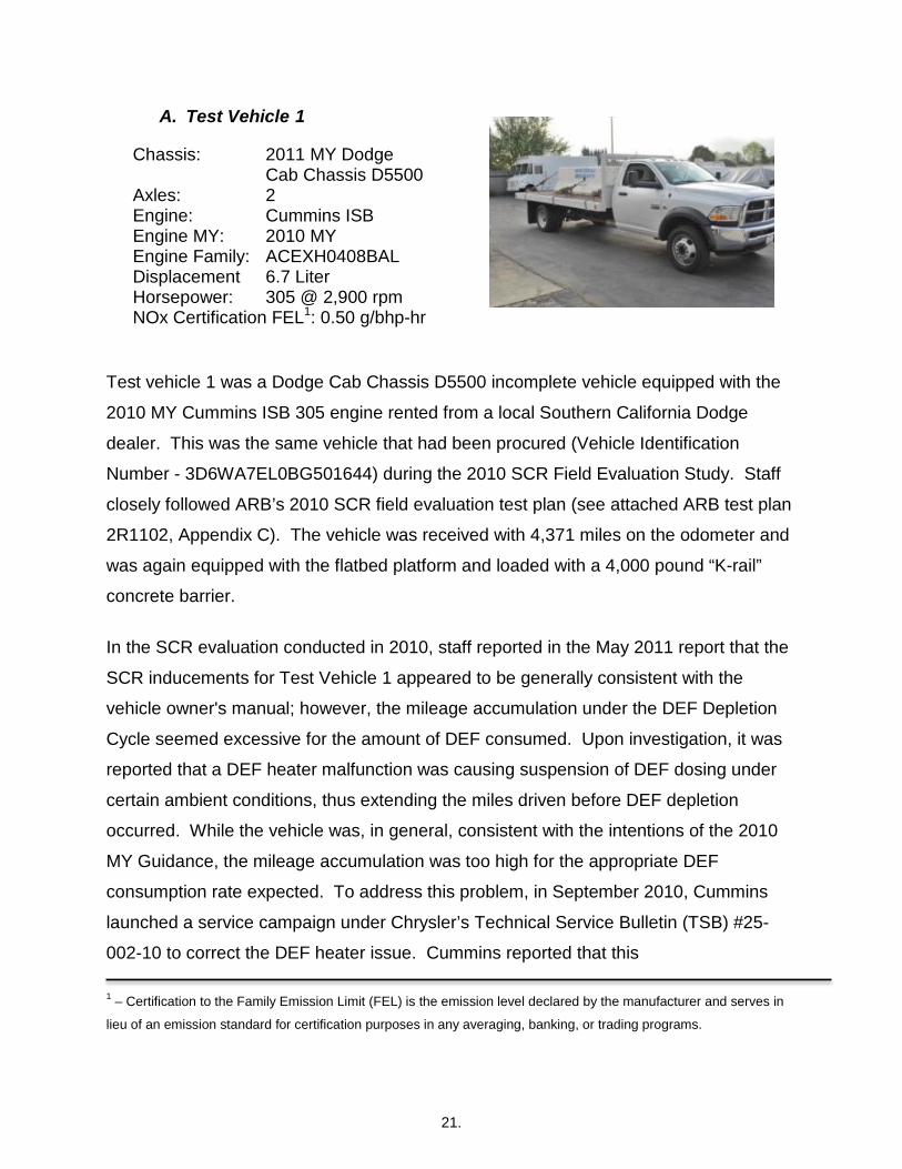
A. Test Vehicle 1
Chassis: 2011 MY Dodge Cab Chassis D5500 Axles: 2 Engine: Cummins ISB Engine MY: 2010 MY Engine Family: ACEXH0408BAL Displacement 6.7 Liter Horsepower: 305 @ 2,900 rpm NOx Certification FEL1: 0.50 g/bhp-hr
Test vehicle 1 was a Dodge Cab Chassis D5500 incomplete vehicle equipped with the
2010 MY Cummins ISB 305 engine rented from a local Southern California Dodge
dealer. This was the same vehicle that had been procured (Vehicle Identification
Number - 3D6WA7EL0BG501644) during the 2010 SCR Field Evaluation Study. Staff
closely followed ARB’s 2010 SCR field evaluation test plan (see attached ARB test plan
2R1102, Appendix C). The vehicle was received with 4,371 miles on the odometer and
was again equipped with the flatbed platform and loaded with a 4,000 pound “K-rail”
concrete barrier.
In the SCR evaluation conducted in 2010, staff reported in the May 2011 report that the
SCR inducements for Test Vehicle 1 appeared to be generally consistent with the
vehicle owner's manual; however, the mileage accumulation under the DEF Depletion
Cycle seemed excessive for the amount of DEF consumed. Upon investigation, it was
reported that a DEF heater malfunction was causing suspension of DEF dosing under
certain ambient conditions, thus extending the miles driven before DEF depletion
occurred. While the vehicle was, in general, consistent with the intentions of the 2010
MY Guidance, the mileage accumulation was too high for the appropriate DEF
consumption rate expected. To address this problem, in September 2010, Cummins
launched a service campaign under Chrysler’s Technical Service Bulletin (TSB) #25-
002-10 to correct the DEF heater issue. Cummins reported that this
1 – Certification to the Family Emission Limit (FEL) is the emission level declared by the manufacturer and serves in
lieu of an emission standard for certification purposes in any averaging, banking, or trading programs.

22.
vehicle had not been repaired as a result of this service campaign but staff remembers
that the vehicle was repaired when ARB returned the vehicle to the dealer after the
initial 2010 SCR evaluation and prior to the launch of the service campaign. Cummins
and Chrysler have no record of this repair under warranty.
Cummins reported that this vehicle had been updated with the latest emission control
software (see Figure Cummins 6.7-1) as of March 11, 2011.
Figure Cummins 6.7-1: Calibration Update Performed March 11, 2011
Cummins stated to staff that the updated software is similar to the 2011 MY SCR control
strategy (but not exact) and is being installed on all on-road 2010 MY 6.7L HDD engines
under Chrysler’s TSB #18-022-REV.B, launched in November 2010. As of late
November 2011, 82 percent of the affected vehicle population received the updated
calibration.
The vehicle underwent the three SCR test cycle evaluations to determine if the software
fixes and updates lead to any changes or improvements in the SCR strategy designs.
Before operating the vehicle, the driver reviewed the 2010 Dodge 5500 Owner’s Manual
to become familiar with the dashboard gauges, warning lights, vehicle controls, and
SCR warning system. The driver warnings and inducements included various displays
on the Electronic Vehicle Information Center (EVIC) located in the center of the
instrument panel (see Figure Cummins 6.7-2) and would be accompanied by periodic
audible warnings.
Since PEMS emissions data was gathered on this vehicle in the 2010 SCR evaluation,
no additional exhaust emissions data was measured under this test project because the
data was considered valid; the emissions data demonstrated that the SCR system

23.
operated as expected controlling NOx emissions under normal operation and in the
depleted mode; NOx emissions did increase when contaminating the DEF tank (i.e.,
completing filling it with water) and tampering with the SCR system. Cummins stated to
ARB staff that the updated SCR software provided no changes to the air/fuel emissions
strategy and therefore, the emissions results would show no changes as were
measured in 2010. Staff’s re-evaluation of this vehicle focused on the SCR calibration
improvements for detecting an SCR related problem and activating the SCR
inducement strategy.
Figure Cummins 6.7-2: Electronic Vehicle Information Center
a) Vehicle 1 - DEF Depletion Cycle
Figure Cummins 6.7-3 below was created by ARB staff as an interpretation of the SCR
driver warning and inducement sequences for this vehicle based on the information
provided in the vehicle owner’s manual and has been approved for use in this report
with Cummins’ permission. Under the DEF Depletion Cycle, the first inducement in the
form of warning messages and chimes should occur when approximately 1,000 miles of
driving remains until DEF runs out. If DEF still has not been added 500 miles after the
initial warnings occurred, the vehicle should enter into a 500 mile countdown sequence
as indicated on the dash mounted display. Once the display reaches zero miles and no

24.
DEF has been added to the vehicle’s DEF tank, the vehicle should not start upon its
next key-off/key-on event.
Figure Cummins 6.7-3: 2010 Cummins’ 6.7L SCR System DEF Depletion Warning Sequence
Day 1
Testing began with the odometer at 4,474 miles, the DEF tank filled to 17 percent of its
capacity as displayed on the EVIC, and the diesel fuel gauge at about the 25 percent
mark. The vehicle was operated for 321 miles for the day and required two refueling

25.
events that took place at 4,504 miles and 4,686 miles on the odometer. The vehicle
experienced no associated driver warnings or other SCR inducements and finished with
the DEF level at 14 percent of its full capacity as indicated on the EVIC, and the diesel
fuel gauge reading 75 percent of capacity (odometer = 4,795 miles).
Day 2
Operation began the next day with the DEF level still showing 14 percent full (odometer
= 4,795 miles). The vehicle was driven 70 miles (odometer = 4,865 miles) and the
vehicle was refueled with 20 gallons of diesel fuel. After accumulating 212 additional
miles (odometer = 5,077 miles), the vehicle was keyed-off for another refueling event.
The vehicle was filled with 21.6 gallons of diesel fuel bringing the fuel level back to 100
percent of capacity. The vehicle was restarted and after two miles of driving (odometer
= 5,079) with the DEF Level Gauge reading 9 percent of full capacity, the first the first
driver warning took place with the EVIC displaying the message “Low DEF Refill Soon”
and then extinguished about minute later (see Figure Cummins 6.7-3, Stage 1). As the
mileage accumulation continued for the day, the driver observed the same message
again at an odometer reading of 5,214 miles (upon restart with an associated chime),
5,248 miles, and 5,297 miles (with an associated chime). During this time staff added
21 gallons of diesel fuel with an odometer reading of 5,252 miles. Staff returned to
ARB’s El Monte facility with the DEF Level Gauge reading four percent of full capacity,
and the EVIC was displaying the message “Low DEF Refill Soon” where one chime
occurred upon the display of the message (odometer = 5,327 miles). With testing
completed for the day, staff shutdown the vehicle.
Day 3
When staff started the vehicle on Day 3, the DEF level indicator showed 5 percent
remaining, the “Low DEF Refill Soon” message appeared and one chime occurred
warning the driver of low DEF. The message extinguished when the vehicle operation
began, but the message and chime occurred again 20 miles after starting the test route
(odometer = 5,347 miles). As mileage accumulation continued, the “Low DEF Refill

26.
Soon” warning message appeared and extinguished within a few minutes approximately
every 50 miles and upon vehicle start up. The DEF Level Gauge dropped to 0%
capacity with an odometer reading of 5,545 miles. Nine miles after the DEF tank
reached empty (odometer = 5,554 miles), the amber DEF light illuminated and the EVIC
displayed the message “Refill DEF Engine Will Not Restart In 500 Miles” (see Figure
Cummins 6.7-3, Stage 2) initiating the 500 mile countdown sequence (See Figure
Cummins 6.7- 4).
Figure Cummins 6.7- 4: Example of Message Alert, 500 Mile Countdown
As the vehicle counted down from 500 miles to 0 miles, the amber DEF light continued
to illuminate and was accompanied with a periodic audible alert at vehicle start-up and
approximately every 50 miles for the next 100 miles decreasing to about every 25 miles
as the vehicle was driven along the designated test route. Staff returned to ARB’s
El Monte facility with the counter showing 325 miles before the engine no-start condition
was to occur (odometer = 5,733 miles).
Day 4
With the vehicle odometer at 5,733 miles, the vehicle was started the next day and the
EVIC was still showing a DEF level of 0%, and also included the illumination of the DEF
light. As mileage accumulation continued the amber DEF light was continuously
illuminated and was accompanied with a periodic audible alert approximately every 25
miles and upon engine start up while driving the designated test route. The operator

27.
was unable to change the countdown message display while in the countdown mode
(i.e., the EVIC did not show other information that could typically be accessed through
the EVIC display, like outside temperature or fuel economy information). Staff returned
to ARB’s El Monte facility with the no-start counter showing 249 miles left before the no-
start condition would occur. Testing was terminated for the day with the odometer at
5,804 miles.
Day 5
Upon restart on Day 5, the countdown to a no-start condition was still displayed and the
amber DEF light continuously illuminated accompanied by a periodic audible chime
that took place approximately every 25 miles and upon engine start up (i.e., the chime
sounded once at designated mileage intervals and upon vehicle start up). The
frequency of the audible chime increased to about every 10 miles once the countdown
counter reached 100 miles. After driving a total of 497 miles (odometer = 6,051 miles)
since the countdown initiated, the EVIC message displayed “Refill DEF Engine Will Not
Start” (see Figure Cummins 6.7-3, Stage 3). Staff drove for nine more miles with the
audible alert signaling about every two minutes. At this time, staff stopped the vehicle
and then executed a key-off/key-on event but the vehicle failed to start (odometer =
6,060 miles). Staff filled the DEF tank with seven gallons of DEF and initiated a key-on
event. Subsequently, all SCR related warnings extinguished and staff was able to
restart the vehicle. This concluded the DEF Depletion Test Cycle.
In summary, the first driver’s warning occurred at a DEF level of nine percent, well
before the DEF tank level displayed empty, at odometer mileage point 5,079 miles. The
countdown to no-start was reached 475 miles later when the DEF gauge level reached
empty, keeping in mind that manufacturers build in reserve levels that the operator will
not see. As the countdown progressed, this message was accompanied an increasing
frequency of audible chimes. Once the countdown expired and the vehicle was keyed
off, the no-start condition occurred rendering the vehicle unusable until DEF was added
to the system. The results were consistent with the 2010 MY Guidance and there was

28.
some indication that the time between the first warning and triggering the countdown
was reduced from the original 2010 calibration.
b) Vehicle 1 - DEF System Tampering Cycle
Figure Cummins 6.7- 5 below was created by ARB staff as an interpretation of the SCR
driver warning and inducement sequences for this vehicle based on the information
provided in the 2010 vehicle owner’s manual and has been approved for use in this
report with Cummins’ permission. Under the DEF System Tampering Cycle, the 500
mile countdown should commence 250 miles after the initial driver warning occurs
accompanied by periodic chimes. Once the display reaches zero miles and the
tampered event has not been remedied, the vehicle should not start upon its next key-
off/key-on event.
Figure Cummins 6.7- 5: Cummins’ 2010 6.7L SCR System Tampering and Contamination Warning Sequence

29.
Day 1
In order to initiate the DEF System Tampering Cycle, staff disconnected the DEF doser
injector to represent a tampering event. The SCR inducement evaluation began with
the odometer showing 6,060 miles. After driving two miles (odometer = 6,062 miles),
the vehicle set a MIL (that stayed on throughout the test cycle) and the EVIC displayed
the message “Service DEF System - See Dealer” (see Figure Cummins 6.7-5, Stage 1).
As the mileage accumulation continued for the day, the driver observed the same
message at an odometer reading of 6,091 miles (see Figure Cummins 6.7-6) and 6,141
miles (with an associated chime) extinguishing a few minutes after it displayed.
Figure Cummins 6.7-6: Tampering Message
After an additional 50 miles driven (odometer = 6,191 miles) the SCR system prompted
a new EVIC message showing “Service DEF System Engine Will Not Start In 400 Miles
– See Dealer” (see Figure Cummins 6.7-5, Stage 2) along with an audible chime. Staff
observed that the counter began at 400 miles instead of 500 miles, as was witnessed in
the 2010 evaluation program. Once this message was displayed, the operator was not
able to change the countdown message display while in the countdown mode. As staff
continued to drive the vehicle, the EVIC continually displayed the miles of operation
30.
remaining until the no-start condition would occur and an audible alert sounded at 50
mile intervals for the first 100 miles of operation (odometer = 6,291 miles) and initiated
upon every engine start up. The chime frequency increased to every 25 mile interval for
the next 200 miles of operation and finally every 10 miles during the last 100 miles of
operation. The countdown expired after accumulating 397 miles (odometer = 6,588
miles) triggering a new EVIC message, “Service DEF System Engine Will Not Start –
See Dealer” (see Figure Cummins 6.7-5, Stage 3). Staff drove for two additional miles
beyond the countdown expiration and executed a key-off/key-on event but the vehicle
did not start (odometer = 6,590 miles).
Day 2
Staff attempted a re-tamper event to determine if the vehicle would detect a repeat
tampering event and return to a no-start condition in short order. To initiate this event,
staff reconnected the DEF doser injector and cleared codes with a generic scan tool
and upon restart the vehicle immediately returned to normal engine operation. Staff
immediately disconnected the doser injector to determine if the vehicle would seek final
inducement per the 2011+ MY Guidelines (odometer = 6,590 miles) despite being a
2010 certified engine under the 2010 MY Guidance. The driver drove the designated
test route and after 14 miles the EVIC displayed the message, Service DEF System –
See Dealer (odometer = 6,604 miles) and illuminated the MIL. In addition, the audible
chime alert occurred periodically as with the initial tampering event. The driver
continued on the designated route and after 146 miles of operation since disconnecting
the doser injector (odometer = 6,736 miles), with the MIL still illuminated, the EVIC
displayed the message “Service DEF System Engine Will Not Start In 400 Miles – See
Dealer.” After driving an additional 101 miles, staff stopped the vehicle at ARB’s El
Monte facility and terminated the repeat tampering event because the vehicle did not
return to search for a safe harbor event within one hour (odometer = 6,837 miles).
For the DEF Tampering Cycle, the vehicle performed similar to the original 2010 MY
calibration by again instituting audible alerts, visual messages and illuminating the MIL
to alert the driver of an existing DEF system issue. Staff noted that both calibration

31.
strategies quickly detected each of the test conditions but the updated calibration was
able to initiate the countdown strategy almost 50 percent faster than the original 2010
MY calibration. In addition, the updated SCR inducement strategy began the
countdown criterion at 400 miles as opposed to the 500 mile countdown strategy utilized
for the original 2010 MY calibration. Overall, the updated SCR strategy is working as
designed and closely follows the inducement strategies set forth in the vehicle owner’s
manual, the 2010 MY Guidance, and in some aspects, the 2011+ MY Guidelines.
Day 3
Staff reconnected the DEF doser injector and upon restart the vehicle driver warnings
extinguished. Staff drove the vehicle 132 miles verifying that the vehicle returned to
normal engine operation. This concluded the DEF System Tampering Cycle.
c) Vehicle 1 - DEF Contamination Cycle
As shown in Figure Cummins 6.7-4, under the DEF Contamination Cycle, the 500 mile
countdown should commence 250 miles after the initial driver warning occurs
accompanied by periodic chimes. Once the display reaches zero miles and the
contamination event has not been remedied, the vehicle should not start upon its next
key-off/key-on event.
Day 1
To initiate the DEF Contamination Cycle, the DEF tank was drained of DEF and filled
with water to a capacity of 100 percent as shown on the EVIC DEF display (odometer =
6,969 miles). The vehicle was operated for 12 miles (odometer = 6,981 miles) over the
designated test route when the SCR system detected contaminated DEF and displayed
the EVIC message “Service DEF System – See Dealer”, and was accompanied by an
audible chime (see Figure Cummins 6.7-5, Stage 1). Additionally, although not
prescribed in the owner’s manual, the MIL also illuminated at this time. The message
was present for about a minute and then extinguished but the MIL stayed on
continuously. The EVIC message would re-appear periodically throughout the day

32.
occurring at 7,024 miles (restart event included an audible chime), 7,033 miles and
7,056 miles. Staff returned to ARB’s El Monte facility with the same EVIC message
displayed and the MIL light still illuminated (odometer = 7,057 miles).
Day 2
As soon as the engine was started the next day, the EVIC displayed the message
“Service DEF System – See Dealer” and illuminated the MIL (odometer = 7,057 miles).
After operating the vehicle for 100 miles since the first driver warning message took
place (odometer = 7,081 miles), the EVIC message changed to “Service DEF System
Engine Will Not Start In 400 Miles – See Dealer” (see Figure Cummins 6.7-5, Stage 2),
and continued to be accompanied by an illuminated MIL and a periodic audible chime.
Staff observed that the counter began at 400 miles instead of 500 miles, as was
witnessed in the 2010 evaluation program. Once this message was displayed, the
operator was not able to change the countdown message display while in the
countdown mode. As staff continued to drive the vehicle, an audible alert sounded at
an increased frequency of about 50 miles for the first 100 miles of the countdown then
25 miles for the next 200 miles and finally every 10 miles for the last 100 miles. The
MIL stayed illuminated throughout the entire countdown mode. The countdown expired
after accumulating 398 miles (odometer = 7,479 miles) triggering a new EVIC message,
“Service DEF System Engine Will Not Start – See Dealer” (see Figure Cummins 6.7-5,
Stage 3). As the message displayed, staff was in the process of pulling into ARB’s El
Monte facility. Staff executed a key-off/key-on event, but the vehicle did not start
(odometer = 7,479 miles). The total number of miles to reach a no-start condition from
the time of detecting poor quality DEF was 498 miles. Since there was no emission
measurement taken, staff could not determine where NOx emissions might have been
considered out of control but based on past experience with this vehicle, the PEMS data
conducted in 2010 showed that the vehicle was not able to control NOx shortly after
starting the vehicle with water in place of DEF.
For the DEF Contamination Cycle, the vehicle performed similar to the original 2010 MY
calibration by again instituting audible alerts, visual messages and illuminating the MIL

33.
to alert the driver of an existing DEF system issue. Staff noted that both calibration
strategies quickly detected each of the test conditions but the updated calibration was
able to initiate the countdown strategy almost 50 percent faster than the original 2010
MY calibration. In addition, the updated SCR inducement strategy began the
countdown criterion at 400 miles as opposed to the 500 mile countdown strategy utilized
for the original 2010 MY calibration. Overall, the updated SCR strategy is working as
designed and closely follows the inducement strategies set forth in the vehicle owner’s
manual, the 2010 MY Guidance, and in some aspects, the 2011+ MY Guidelines.
Following this no-start condition, staff used a generic OBD scan tool to review the
stored DTC information and then cleared the trouble codes. With the stored trouble
codes removed, and all warning messages and visual/audible alerts cleared, the vehicle
was started and returned to normal operation. With this last cycle completed, staff
made arrangements to return the vehicle back to the local Dodge dealer from where the
vehicle was rented.
d) Vehicle 1- Inducement Test Summary
The primary SCR inducement for this vehicle included the driver warning accompanied
by periodic audible chimes, warning messages and finally triggering a 500 mile
countdown driver message that ultimately led to a no-start condition. Keeping in mind
that technically this vehicle is only required to be consistent with the 2010 MY
Guidance, Figure Cummins 6.7-7, shows a direct comparison of this vehicle with the
SCR calibration evaluated in 2010 and the updated calibration evaluated in 2011.

34.
Figure Cummins 6.7-7: Cummins' SCR Calibration Evaluated in 2010 vs. 2011 for a 2010 Engine
• All numbers represent miles driven.
The updated calibration software has incorporated SCR strategy enhancements and
was updated on the ARB tested 2010 MY 6.7L HDD engine in March 2011. During the
2010 SCR evaluation program, staff experienced problems when conducting the DEF
Depletion Cycle due to a DEF heater problem. This problem in conjunction with the 500
mile counter resetting in the midst of counting down allowed additional mileage to
accumulate beyond Cummins’ SCR strategy criteria. These problems were corrected
with service updates through Chrysler’s Dodge dealer network. Under the DEF
Depletion Cycle, this vehicle was consistent with both the 2010 MY Guidance and the
2011+ MY Guidelines.
For the DEF Contamination and DEF System Tampering Cycles, the updated SCR
inducement strategy performed similar to the original 2010 MY calibration by again
instituting audible alerts, visual messages and illuminating the MIL to alert the driver of
an existing DEF system issue. Staff noted that both calibration strategies quickly
detected each of the test conditions but the updated calibration was able to initiate the
Cummins 6.7L 2010 MY Engine
Mile
s Tra
vele
d Af
ter
Firs
t Driv
er W
arni
ng to
Re
ach
Coun
tdow
n Cr
iterio
n
Coun
tdow
n to
“N
O
Star
t” C
riter
ion
Mile
s Tra
vele
d Du
ring
Coun
tdow
n to
Rea
ch
No
Star
t Con
ditio
n
Tota
l Mile
s Tra
vele
d In
itial
Det
ectio
n
Mile
age
Diff
eren
ce to
Re
ach
“No
Star
t “
Cond
ition
CYCLES EVALUATED 2010 CY 2011 CY 2010 CY 2011 CY 2010 CY 2011 CY 2010 CY
(A)
2011 CY
(B)
Diff = (A) - (B)
DEF Depletion 934 475 500 500 629 497 1563 972 591
DEF Tampering 250 130 500 400 496 397 746 526 220
DEF Contamination 249 100 500 400 497 398 746 498 248

35.
countdown strategy almost 50 percent faster than the 2010 MY calibration. In addition,
the updated SCR inducement strategy began the countdown criterion at 400 miles for
each of these cycles as opposed to the 500 mile countdown strategy utilized for the
original 2010 MY calibration. Overall, the updated SCR strategy is working as designed
and closely follows the inducement strategies set forth in the vehicle owner’s manual,
the 2010 MY Guidance but was not fully consistent with the intended 2011+ MY
Guidelines when operating in a contaminated or tampered mode .
Staff demonstrated during the DEF Contamination Cycle that the generic scan tool can
reset the vehicle when the no-start condition occurred; thus, allowing staff to reset the
trouble codes and allow the driver to restart the vehicle. Staff contacted Cummins
regarding this issue after completing the 2011 evaluation. Cummins responded that
since updating the SCR calibration in November 2010, Cummins launched a new
service campaign in May 2011, installing a further enhanced SCR calibration update on
all 6.7L engines built before January 1, 2011. The new software update enhances the
SCR inducement strategy by lowering the countdown of contamination or tampering
detection from 400 miles to 200 miles. If a re-tampered event is detected, the
countdown mileage counter will reinitiate in less than 200 miles. Although a generic
scan tool will be able to clear a no-start condition, the SCR system will retain a
tampered event in its memory for 40 hours and should the vehicle be re-tampered, the
counter may restart at the value where it stopped when a previous fault was temporarily
remedied, or at a minimum of 50 miles. The most recent campaign would more closely
align with the 2011+ MY Guidelines. At this time, the effort by Cummins to update their
2010 in use engines to the 2011+ MY Guidelines is totally voluntary on their part.
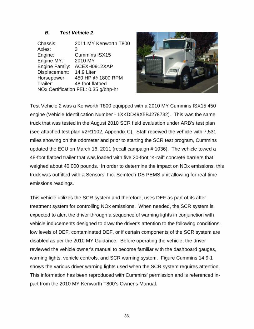
36.
B. Test Vehicle 2
Chassis: 2011 MY Kenworth T800 Axles: 3 Engine: Cummins ISX15 Engine MY: 2010 MY Engine Family: ACEXH0912XAP Displacement: 14.9 Liter Horsepower: 450 HP @ 1800 RPM Trailer: 48-foot flatbed NOx Certification FEL: 0.35 g/bhp-hr
Test Vehicle 2 was a Kenworth T800 equipped with a 2010 MY Cummins ISX15 450
engine (Vehicle Identification Number - 1XKDD49X5BJ278732). This was the same
truck that was tested in the August 2010 SCR field evaluation under ARB’s test plan
(see attached test plan #2R1102, Appendix C). Staff received the vehicle with 7,531
miles showing on the odometer and prior to starting the SCR test program, Cummins
updated the ECU on March 16, 2011 (recall campaign # 1036). The vehicle towed a
48-foot flatbed trailer that was loaded with five 20-foot “K-rail” concrete barriers that
weighed about 40,000 pounds. In order to determine the impact on NOx emissions, this
truck was outfitted with a Sensors, Inc. Semtech-DS PEMS unit allowing for real-time
emissions readings.
This vehicle utilizes the SCR system and therefore, uses DEF as part of its after
treatment system for controlling NOx emissions. When needed, the SCR system is
expected to alert the driver through a sequence of warning lights in conjunction with
vehicle inducements designed to draw the driver’s attention to the following conditions:
low levels of DEF, contaminated DEF, or if certain components of the SCR system are
disabled as per the 2010 MY Guidance. Before operating the vehicle, the driver
reviewed the vehicle owner’s manual to become familiar with the dashboard gauges,
warning lights, vehicle controls, and SCR warning system. Figure Cummins 14.9-1
shows the various driver warning lights used when the SCR system requires attention.
This information has been reproduced with Cummins’ permission and is referenced in-
part from the 2010 MY Kenworth T800’s Owner’s Manual.

37.
Figure Cummins 14.9-1: Driver Warning Lights/Information used by SCR System
Diesel Level Gauge: Red Lamp Indicates Problem With SCR System
Check Engine Light: Secondary Lamp Notification That SCR Has Problem
Driver Information Display: Displays Messages to the Driver Including Problems with the SCR System
Stop Engine Light: The illumination of this lamp indicates that the vehicle is experiencing a major problem; e.g., a 5 mph limited speed event
Malfunction Indicator Light: The MIL illuminates when the On Board Diagnostics (OBD) detects a malfunction related to the emissions control system. The illuminated MIL indicates that the engine needs to be serviced at the first available opportunity and can be illuminated along with any of the engine indicator lamps.
Although this engine was certified as a 2010 MY engine, because the ECU was
updated, the vehicle was evaluated to determine if the SCR related warnings and
inducements closely followed the 2011+ MY Guidelines (see Figure 12) and the 2010
MY Guidance (see Figure 11).
a) Vehicle 2 - DEF Depletion Cycle
The chart below, Figure Cummins 14.9-2, was created by ARB staff with Cummins’
permission as an interpretation of the 2010 MY Kenworth T800 Owner’s Manual
depicting the stages of escalating driver warnings and alerts expected for the DEF
Depletion Cycle.

38.
Figure Cummins 14.9-2: 2010 MY Cummins’ Driver Warnings and Inducements for Depletion
STAGE 2Below 1/8th tank but above empty
STAGE 1~10% DEF or 1/8TH of TANK
SOLID
DEF TANK LEVEL
LAMP INDUCEMENT
NOTIFICATION
FLASHING
FLASHING
STAGE 3Tank close to empty
STAGE 4Tank is empty
After the engine has been turned off or prolong idle. FLASHING
DEF DEPLETION
The first driver warning was expected to be triggered when the truck’s DEF level drops
below 1/8 of tank capacity (see Stage 1). As DEF was depleted, the driver should be
subjected to additional warnings as indicated in Stage 2 (below 1/8 tank but above
empty - DEF level). When the DEF level is close to empty, the additional inducements
should include a check engine light illumination and an engine torque derate (see Stage
3). Ultimately, when the DEF gauge reads empty and the vehicle is turned off or idled
for 20 hours, the vehicle should enter a 5 mph speed limited condition and now
accompanied by a stop engine light (see Stage 4).

39.
Day 1
Staff began the test cycle with the DEF tank reading just above an 1/8th of a tank as
indicated by the DEF Level Gauge on the vehicle’s instrument dash panel (odometer =
9,061 miles) and the diesel fuel gauge reading just below 75 percent full. After driving
18 miles (odometer = 9,079 miles), the first driver warning occurred (see Figure
Cummins 14.9-2, Stage 1), the red DEF gauge light illuminated and the Low DEF
warning message displayed on the Driver Information Display ( DID) (see Figure
Cummins 14.9-3).
Figure Cummins 14.9-3: Driver Information Display Message and Low DEF Warning Light
The driver drove an additional 13 miles (odometer = 9,092 miles) since the first driver
warning occurred and stopped to refuel, adding 33.6 gallons of diesel fuel. Upon restart
the diesel fuel gauge was showing 100 percent fuel with the same driver warnings
previously displayed on the DID. The driver continued to drive an additional 92 miles
and noticed that the red DEF gauge light began to flash (odometer = 9,184 miles)
indicating that Stage 2 had been reached per Figure Cummins 14.9-2. Staff returned to
ARB’s El Monte facility with no changes to the SCR warning system indicators and shut
down the vehicle for the day (odometer = 9,226 miles).

40.
Day 2
Upon vehicle start, the red DEF gauge light began to flash and the DEF gauge showed
empty. After driving 29 miles (odometer = 9,255 miles), and with the DEF gauge light
still flashing, the check engine light illuminated, and the Low DEF warning message
displayed on the DID. Eleven miles later (odometer = 9,266 miles), the driver noticed
that the vehicle had a lack of power especially when trying to accelerate, indicating that
the truck was experiencing an engine derate condition (see Figure Cummins 14.9-2,
Stage 3). Traveling 16 additional miles, staff stopped to refuel adding 36.8 gallons of
diesel fuel bringing the diesel fuel level back up to 100 percent full (odometer = 9,282
miles). Staff returned to ARB’s El Monte facility and shut down the vehicle (odometer =
9,315 miles). Upon restart, the red stop engine light illuminated (see Figure Cummins
14.9-4) along with the other pre-established warnings (see Figure Cummins 14.9-2,
Stage 4).
Figure Cummins 14.9-4: Stop Engine Lamp and Check Engine Light
When attempting to drive the vehicle, the vehicle speed was limited to 5 mph. In total,
the vehicle was driven 236 miles since the first driver warning was displayed. After
turning off the engine, staff added 5 gallons of DEF assuming this would return the
engine to normal operation. Subsequently, staff restarted the vehicle and all driver
warnings and vehicle inducements immediately extinguished and the vehicle returned to
normal operation. The figure below represents the daily DEF Depletion Cycle
emissions and includes markers where certain SCR inducement events occurred along
the test route (see Figure Cummins 14.9-5 below). The events represented in the figure

41.
include the first driver warning, the onset of the engine derate, and the initiation of the
vehicle’s SCR strategy to seek the final inducement event.
Figure Cummins 14.9-5: Daily DEF Depletion Cycle Emissions Data
Note: The PEMS values in this figure were measured values taken during this test program while the vehicle was operated under on-road conditions. The NTE NOx is the on-road measurement of NOx emissions that requires specific engine operation and other criterion for attaining this measurement. The NOx family emission limit (FEL) of 0.35 g/bhp-hr requires emission measurements under laboratory conditions and the Not to Exceed (NTE) 0.52 g/bhp-hr standard requires specific on-road operation for attaining emission measurements. This standard, in addition to the NTE + 0.15 g/bhp-hr measurement allowance, was provided for general reference only. The PEMS unit used for this operation meets the U.S. EPA requirements per 40 CFR 1065.
In regards to the Depletion Cycle, the emission results of this vehicle showed that under
the Depletion Cycle, the vehicle has the capability to control NOx emissions within the
NTE standard but once the DEF gauge reads empty, the vehicle will only stay in control
for about an hour and then NOx will increase significantly. However, the vehicle is
flashing continuous warning signs to the driver and the vehicle is experiencing an
engine derate that would not be an acceptable condition to endure when the driver can

42.
easily stop, add DEF, and return to normal vehicle operation. All prescribed inducement
strategies for this cycle appeared to be consistent with the vehicle owner’s manual
information, the 2010 MY Guidance and the suggested SCR 2011+ MY Guidelines.
b) Vehicle 2 - DEF System Tampering Cycle
Figure Cummins 14.9-6 was created by ARB staff with Cummins’ permission as an
interpretation of the 2010 MY Kenworth T800 Owner’s Manual depicting the stages of
escalating driver warnings and alerts expected for the DEF System Tampering Cycle
and the DEF Contamination Cycle.
Figure Cummins 14.9-6: 2010 MY Cummins’ Driver Warnings & Inducements for DEF Quality or Tampering
LAMP INDUCEMENT
NOTIFICATION
DEF QUALITY OR TAMPERING
STAGE 1aProblem Detected
STAGE 2a10 hrs or 500 mi after detection
STAGE 3a20 hrs/1,000 mi after detection (Quality)
40 hrs/2,000 mi after detection (Tampering)
SOLID
FLASHING
FLASHING
- 5 mph speed after key-off/restart or,- Engine Idles for 20 hrs
When disabled or tampered, the SCR system is expected to trigger driver warnings and
vehicle inducements upon the detection of a non-functioning SCR system. As the
vehicle continues to operate with the disabled or tampered component, the SCR system
is designed to increase the warnings and inducements up to activating a limited speed
condition of 5 mph.

43.
(1) Doser Valve Disconnected
Day 1
Before starting the next test cycle, staff filled the DEF tank to 50 percent capacity with
quality DEF. Staff began the DEF System Tampering Cycle by disabling Test Vehicle
2’s doser valve (odometer = 9,315 miles). The first driver warning occurred after
accumulating nine miles (odometer = 9,324 miles) when the red DEF gauge light began
to flash (see Figure Cummins 14.9-6, Stage 1a). After driving 16 additional miles
(odometer = 9,340 miles), with the red DEF gauge light still flashing, the check engine
light illuminated, the Low DEF warning message displayed on the DID and the vehicle
experienced an engine power derate (see Figure Cummins 14.9-6, Step 2a). The driver
stated that the engine derate was significant, especially when traveling up a grade
(odometer = 9,352 miles) and that the engine power seemed to be reduced by 50
percent. The vehicle was returned to ARB’s El Monte facility with the same active driver
warnings and inducements (odometer = 9,388 miles).
Day 2
The driver commenced his route the next morning with the check engine light still
illuminated and the previous warnings and inducements still active. While in route, staff
stopped to re-fuel adding 33.3 gallons of diesel fuel bringing the diesel fuel level back
up to 100 percent full (odometer = 9,487 miles). The driver continued to drive the
designated route and returned to the ARB El Monte facility (odometer = 9,587 miles).
Staff allowed the vehicle to idle for just over an hour and a half and performed a key-
off/key-on event. Upon completion of the key-of/key on event, staff observed the red
stop engine light was illuminated and the vehicle went into a 5 mph derate. Additionally,
the MIL was still illuminated and the previous warnings and inducements were still
active. When attempting to drive, the vehicle was limited to 5 mph (see Figure
Cummins 14.9-6, Stage 3a). The vehicle was clearly ahead of the 2010 MY Guidance
and obviously much closer to the 2011+ MY Guidelines due to the software updates that
occurred after the original testing of this vehicle in 2010.

44.
The driver reconnected the doser valve and attempted to clear the codes but was
unsuccessful. Subsequently, the vehicle was taken to the Kenworth dealer who cleared
the associated codes and the vehicle returned to normal operation (odometer = 9,611
miles). The work was covered under the vehicle warranty and therefore, ARB did not
incur any costs.
The figure below represents the daily DEF System Tampering Cycle emissions with a
disconnected doser and includes markers where certain SCR inducement events
occurred along the test route (see Figure Cummins 14.9-7 below). The events
represented in the figure include the first driver warning, the onset of the engine derate,
and the presumed initiation of the vehicle’s SCR strategy to seek a safe harbor event.

45.
Figure Cummins 14.9-7: Daily DEF System Tampering Cycle (Disconnected Doser) Emissions Data
Note: The PEMS values in this figure were measured values taken during this test program while the vehicle was operated under on-road conditions. The NTE NOx is the on-road measurement of NOx emissions that requires specific engine operation and other criterion for attaining this measurement. The NOx family emission limit (FEL) of 0.35 g/bhp-hr requires emission measurements under laboratory conditions and the Not to Exceed (NTE) 0.52 g/bhp-hr standard requires specific on-road operation for attaining emission measurements. This standard, in addition to the NTE + 0.15 g/bhp-hr measurement allowance, was provided for general reference only. The PEMS unit used for this operation meets the U.S. EPA requirements per 40 CFR 1065.
The NOx emissions, as expected increased dramatically with the tampering event and
remained high throughout. However, it is clear the initial warnings and especially the
derate condition caught the attention of the driver and would have likely resulted in more
immediate attention than the ARB driver paid here trying to control the final inducement
trigger by delaying the safe harbor event to a more convenient time and place.
Cummins initiative to update in use 2010 engines to be more in line with the 2011+ MY
Guidelines will result in an even greater reduction in tampering emission impacts by
giving strong and immediate driver inducements.

46.
(2) Thermocouple Disconnected
Day 1
Staff attempted a second SCR tampering method by disconnecting the thermocouple on
the outlet side of the SCR catalyst (odometer = 9,620 miles). Immediately after starting
the vehicle, the check engine light illuminated and the “Engine De-rate, See Operator
Manual” warning message displayed on the DID. After driving 39 miles (odometer =
9,659 miles), the driver observed that the vehicle sustained a severe power loss, similar
to what was experienced in the first tampering cycle. The driver noted that the vehicle
could not achieve speeds greater than 50 mph and based on his experience with the
first tampering cycle, the vehicle was probably searching for a safe harbor event to
initiate the final inducement. After driving an additional 35 miles (odometer = 9,694
miles) the DID display changed to “Exhaust (SCR/DEF) Service Required” (see Figure
Cummins 14.9-8). Staff performed a key off/key-on event and the red stop engine light
illuminated (see Figure Cummins 14.9-6, Stage 3a). Subsequently, the vehicle went
into a 5 mph limited speed event..
Figure Cummins 14.9-8: DIC Message – Exhaust (SCR/DEF) Service Required
The drive time to reach the final inducement since the first driver warning was triggered
took approximately two hours or 74 miles. Staff drove the vehicle with the 5 mph
inducement for two miles, back to the ARB El Monte facility, shut off the engine and
reconnected the thermocouple (odometer = 9,696 miles). Staff restarted the engine,

47.
apparently triggering the SCR system into a “self-healing” reset which extinguished the
SCR-related driver warnings and inducements. With the warning lights cleared, staff
noted that the message “Check Engine History” was displayed on the DID. Staff drove
the vehicle and experienced an engine power derate within 12 miles (odometer = 9,708
miles). Staff continued to drive and after completing 62 additional miles of operation,
the vehicle’s power was restored to normal and only the message “Check Engine
History” was displayed (odometer = 9,770 miles). This concluded the DEF System
Tampering Cycle.
The figure below represents the DEF System Tampering Cycle emissions with a
disconnected thermocouple and includes markers where certain SCR inducement
events occurred along the test route (see Figure Cummins 14.9-9 below). The events
represented in the figure include the first driver warning, the onset of the engine derate,
and the assumed initiation of the vehicle’s SCR strategy to seek a safe harbor.

48.
Figure Cummins 14.9-9: Daily DEF System Tampering Cycle (Disconnected Thermocouple) Emissions Data
Note: The PEMS values in this figure were measured values taken during this test program while the vehicle was operated under on-road conditions. The NTE NOx is the on-road measurement of NOx emissions that requires specific engine operation and other criterion for attaining this measurement. The NOx family emission limit (FEL) of 0.35 g/bhp-hr requires emission measurements under laboratory conditions and the Not to Exceed (NTE) 0.52 g/bhp-hr standard requires specific on-road operation for attaining emission measurements. This standard, in addition to the NTE + 0.15 g/bhp-hr measurement allowance, was provided for general reference only. The PEMS unit used for this operation meets the U.S. EPA requirements per 40 CFR 1065.
Under the DEF System Tampering Cycle, the emissions also increased significantly
when disconnecting SCR related components. Staff performed two types of tampering
events where the DEF doser injector was disconnected and later disconnected the SCR
thermocouple. With regards to the initial alert for both tampering events, the SCR
system triggered the first SCR driver warning within one hour and are consistent with
suggested 2011+ MY Guidelines. In regards to seeking final inducement within four
hours (approximately 200 miles), both tampering cases were consistent with the 2011+
MY Guidelines. Keep in mind that this vehicle was a 2010 MY certified engine and was

49.
only required to meet the 2010 MY Guidance, so Cummins’ voluntary calibration update
significantly improved the time/mileage points for warnings and inducements.
c) Vehicle 2 - DEF Contamination Cycle
In the case of DEF contamination, the SCR system is expected to detect NOx
noncompliance and trigger driver warnings and vehicle inducements. As the vehicle
continues to operate with poor quality DEF, the SCR system is designed to increase the
warnings and inducements up to activating a limited speed condition of 5 mph. The
SCR system should follow the same stages of escalating driver warnings and
inducements shown in Figure Cummins 14.9-6.
Day 1
Staff prepared for this test cycle by draining the DEF tank and filling it approximately
half full with deionized water. The vehicle’s diesel fuel tank was also filled to
approximately half of its capacity as indicated on the fuel gauge. Staff began operating
the vehicle over the designated test route (odometer = 9,770 miles) and drove for just
over an hour and a half before returning to ARB’s El Monte facility for the evening
(odometer = 9,844 miles). No driver warnings or inducements were experienced during
this time of operation.
Day 2
Staff began driving the test route the next day and within a half an hour (odometer =
9,865 miles) the driver experienced a power derate and the first driver warning occurred
with the DID displaying the message “Exhaust (SCR/DEF) Service Required” (see
Figure Cummins 14.9-6, Stage 2a). Traveling 11 additional miles, staff stopped to
refuel adding 72.9 gallons of diesel fuel (odometer = 9,876 miles). The driver continued
to drive the vehicle stopping to top off the fuel tank, adding 13.0 gallons of diesel fuel
(odometer = 9,944 miles). The driver decided to test if the vehicle would be in a safe
harbor seeking mode based on the refuel event, then continued the test route and
returned to ARB’s El Monte facility (odometer = 10,044 miles) with the same SCR driver

50.
warning alerts displayed. Staff performed a key-off/key-on event and the red Stop
Engine light illuminated (see Figure Cummins 14.9-6, Stage 3a) and the vehicle was
immediately restricted to a 5 mph speed limit. The drive time to reach the final
inducement since the first driver warning was triggered took approximately four hours
(179 miles traveled). Staff drained the water from the DEF tank and filled it with five
gallons of quality DEF and then cleared the codes using Cummins’ software (this
software was purchased by ARB from Cummins) which cleared all associated SCR
warnings and inducements. The vehicle returned to normal vehicle operation. This
concluded the DEF Contamination Cycle.
The figure below represents the DEF Contamination Cycle emissions and includes
markers where certain SCR inducement events occurred along the test route (see
Figure Cummins 14.9-10 below). The events represented in the figure include the first
driver warning, the onset of the engine derate, and the presumed initiation of the
vehicle’s SCR strategy to seek the final inducement event.

51.
Figure Cummins 14.9-10: Daily DEF Contamination Cycle Emissions Data
Note: The PEMS values in this figure were measured values taken during this test program while the vehicle was operated under on-road conditions. The NTE NOx is the on-road measurement of NOx emissions that requires specific engine operation and other criterion for attaining this measurement. The NOx family emission limit (FEL) of 0.35 g/bhp-hr requires emission measurements under laboratory conditions and the Not to Exceed (NTE) 0.52 g/bhp-hr standard requires specific on-road operation for attaining emission measurements. This standard, in addition to the NTE + 0.15 g/bhp-hr measurement allowance, was provided for general reference only. The PEMS unit used for this operation meets the U.S. EPA requirements per 40 CFR 1065.
As expected, under the DEF Contamination Cycle, the emissions increased significantly
when adding water in place of DEF. During the DEF Contamination Cycle the initial
detection for triggering the first SCR driver warning took just over two hours (95 miles
traveled) and was accompanied by a derate. ARB believes that this first warning is not
fully consistent with the 2011+ MY Guidelines which suggested a one hour
(approximately 50 miles) detection of noncompliance and notification to the operator.
However, this engine was a certified 2010 MY engine and was consistent with the
applicable 2010 MY Guidance information for this engine. ARB is currently in
discussions with the manufacturer to determine if the results for initiating the first driver

52.
warning for identifying contaminated DEF met Cummins’ design criteria of their
calibration update. Additionally, the vehicle did seek final inducement within four hours
or 200 miles after triggering the first driver warning which is consistent with the 2011+
MY Guidelines.
d) Vehicle 2 - Baseline Test Cycle
Baseline testing began with the DEF tank filled to 40 percent capacity with quality DEF
and the diesel fuel tank filled to about 90 percent capacity (odometer=10,044 miles).
The baseline portion of this test program represents the average typical emissions the
vehicle generates under normal vehicle operation. Staff drove this vehicle for four days
and accumulated 557 miles establishing baseline NOx emissions data (odometer =
10,601 miles). The daily baseline emissions are represented in Figure Cummins 14.9-
11 below. As you can see, this vehicle maintained very good NOx control throughout
most of the test route, relative to its 0.52 g/bhp-hr NTE certified level, and never
exceeded 1.0 g/bhp-hr for any of the segments. The legitimate NTE points, accounting
for the measurement allowance, were minimally exceeded on only two of the driving
segments.

53.
Figure Cummins 14.9-11: Daily Baseline Emissions Data
Note: The PEMS values in this figure were measured values taken during this test program while the vehicle was operated under on-road conditions. The NTE NOx is the on-road measurement of NOx emissions that requires specific engine operation and other criterion for attaining this measurement. The NOx family emission limit (FEL) of 0.35 g/bhp-hr requires emission measurements under laboratory conditions and the Not to Exceed (NTE) 0.52 g/bhp-hr standard requires specific on-road operation for attaining emission measurements. This standard, in addition to the NTE + 0.15 g/bhp-hr measurement allowance, was provided for general reference only. The PEMS unit used for this operation meets the U.S. EPA requirements per 40 CFR 1065.
e) Vehicle 2 - Emission Measurements
Test Vehicle 2 was outfitted with a PEMS unit which measured the vehicles emissions
as the vehicle was operated over the designated test route. Emissions were measured
under each of the prescribed test cycles: the Baseline Cycle, the DEF System
Tampering Cycles (disconnection of the doser injector and SCR catalyst thermocouple)
and the DEF Contamination Cycle.
Figure Cummins 14.9-12 is a summary of the average NTE NOx emissions measured
for each of these test cycles. It should be noted that staff utilized NTE zone emission

54.
measurements to compare the emission results for each test cycle. The Family
Emissions Limit (FEL) is also shown on the chart but the test requirement to conduct a
certification type test requires an engine dynamometer under laboratory
conditions. This standard was only included on the chart for informational purposes.
The Baseline Cycle NOx emissions were 0.459 g/bhp-hr and met the NTE NOx
standard of 0.52 g/bhp-hr. The DEF Depletion Cycle’s PEMS measurements were
taken over two days from the time the vehicle began the DEF Depletion Cycle until the
vehicle went into a 5 mph limited speed derate. Under this cycle the NTE NOx
emissions averaged 0.490 g/bhp-hr. Just prior to the vehicle experiencing a 5 mph
limited speed inducement and with the DEF tank completely empty, NOx emissions
increased to 1.033 g/bhp-hr indicating that while the driver thought the DEF tank was
empty, there was DEF in the reserve which allowed the vehicle to remain in compliance
for some time.
The NTE NOx emissions for the DEF Contamination and DEF System Tampering
Cycles were about five times higher than the baseline NTE results ranging from 1.994 to
2.441 g/bhp-hr, respectively.

55.
Figure Cummins 14.9-12: Vehicle 2: NOx Emission Data Summary
Note: The PEMS values in this figure are the average NOx NTE emissions taken during this test program while the vehicle was operated under on-road conditions. The NOx family emission limit (FEL) of 0.35 g/bhp-hr requires emission measurements under laboratory conditions. This standard, in addition to the NTE standard of 0.52 g/bhp-hr measurement allowance, was provided for general reference only. The PEMS unit used for this operation meets the U.S. EPA requirements as per 40 CFR 1065.
f) Vehicle 2 - Inducement Test Summary
ARB staff operated this Test Vehicle 2 under various test cycles comparing the vehicle’s
SCR-related driver warnings and inducements to those supplied in the vehicle owner’s
manual and their consistency with the 2010 MY Guidance and/or the 2011+ MY
Guidelines. ARB staff checked the driver warnings and inducements under the
following cycles: DEF Depletion Cycle, DEF System Tampering Cycle, and DEF
Contamination Cycle.
Comparing the SCR warnings and inducements strategies with the vehicle owner’s
manual showed many consistencies with one slight difference with the DEF System

56.
Tampering and DEF Contamination Cycles. Under these cycles, the driver noted that
the time to reach the limited speed severe inducement event was reduced by 50
percent.
It is important to note that this was a follow up to the test program conducted on this
same vehicle in mid-2010, and technically, this vehicle is only required to be consistent
with the 2010 MY Guidance. In the May 2011 SCR evaluation report, ARB staff stated
that this vehicle (equipped with the 2010 MY calibration) experienced issues in reaching
the 5 mph final inducement for all three evaluated test cycles. In November 2010,
Cummins recalled the affected vehicles recalibrating the ECU to correct various SCR
inducement strategies (Recall # C1036). Based on ARB’s new study after completion of
the test cycles, it was disclosed that the new calibration did in fact resolve the problems
identified in the 2010 study. Cummins’ voluntarily revised software that enhanced the
SCR strategy by triggering driver warnings and engine-derate events sooner and also
allowed each of the evaluated test cycles to reach the final 5 mph severe inducement.
The problems experienced would be intolerable for any driver on their daily route.
In conclusion, the new calibration was consistent with the 2010 MY Guidance and
closely followed the suggested SCR 2011+ MY Guidelines presented at ARB’s July
2010 SCR Workshop, although as mentioned previously, this engine only needed to be
consistent with the 2010 MY Guidance.

57.
VI. Continued Evaluation of 2010+ NOx Control Strategies
ARB staff evaluated three heavy-duty vehicles equipped with a 2010 or 2011 MY HDD
engine (two vehicles using engines with SCR-equipped technology and one vehicle
utilizing an engine with EGR but no SCR emission control technology). The SCR
equipped vehicles evaluated included a 2011 MY Freightliner Cascadia Class 8 truck,
equipped with a 2011 MY Detroit Diesel (DDC) 12.8L engine (Test Vehicle 3), a 2010
MY Volvo Class 8 truck, equipped with a 2010 MY Volvo 12.8L engine (ECU
recalibrated with some 2011 MY SCR attributes (Test Vehicle 4), and the non-SCR
vehicle was a 2012 MY International Class 8 truck, equipped with a 2011 MY Navistar
MaxxForce 13 engine (Test Vehicle 5).
Test Vehicles 3 and 4 underwent these four SCR test cycle evaluations as followed in
ARB’s Test Plan #1Q1102 (see Appendix D) to monitor the manufacturers’ SCR
detection and inducement strategies.
• DEF Depletion Cycle – continued vehicle operation to deplete the DEF tank until
the vehicle experiences a no-start condition, or a 5 mph maximum speed limit, or
an idle-only operation.
• DEF Contamination Cycle – continued vehicle operation with water instead of
DEF until the vehicle experiences a no-start condition, or a 5 mph maximum speed
limit, or an idle-only operation.
• DEF System Tampering Cycle – continued operation after disabling the SCR until
the vehicle experiences a no-start condition, or a 5 mph maximum speed limit, or
an idle-only operation.
• Dilution Test Cycle – continued operation with a blend of water and DEF to check
if and when a diluted DEF mixture will cause the SCR driver warnings and engine
inducements to initiate. The purpose of this evaluation is to determine if the SCR
system is capable of detecting a diluted DEF concentration as opposed to
completely filling the DEF tank with water. The vehicles were not driven to final
inducement under this test cycle.
58.
Typically, these strategies include a sequence of visual and/or audible warnings on the
instrument panel (e.g., warning lights, chimes, and/or text message displays) indicating
the DEF supply was low or a problem had been identified. As additional mileage is
accumulated without remedying the problem or refilling the DEF supply, further driver
inducements should occur, such as power derates or speed limits (which allow
continued operation of the truck). Ultimately, if the problem is not corrected, a severe
inducement or final immobilization in the form of a no-start condition, or a 5 mph
maximum speed limit, or an idle-only operation should be triggered once the vehicle
reaches a safe harbor (e.g., when diesel refueling occurs, the engine is keyed-off, or the
vehicle is parked at idle for an extended period of time). Depending on the certified MY
of the engine, the vehicles were evaluated to determine if the SCR driver warnings and
inducements were consistent with the vehicle owner’s manuals, and/or the 2010 MY
Guidance (see Figure 11), and/or the 2011+ MY Guidelines (see Figure 12). Because
the vehicles are being driven on freeway routes, staff assumes a one hour threshold will
be achieved after traveling about 50 miles and a four threshold will be achieved after
traveling about 200 miles.
Additionally, Test Vehicles 3 and 4 were outfitted with a Sensors, Inc. Semtech-DS
PEMS unit which measured the vehicles’ emissions as the vehicle was operated over
the designated test route. Emissions were measured for each of the four test conditions
described above and a baseline condition. The baseline condition represents the
average typical emissions the vehicles generated under normal vehicle operation.
The non-SCR equipped vehicle (Test Vehicle 5) was operated under separate test
conditions (shown below) to determine if any driver alerts or vehicle inducements were
created following ARB’s Test Plan #1Q1102 (see Appendix D).
• EGR Tampering Cycle – continued operation with a tampered EGR system
observing and documenting all (if any) driver warnings, vehicle performance
issues caused by this tampering event and fuel economy impacts.

59.
• Lean Cruise Cycle – continued operation to identify if any indication of engine
management strategy exists to achieve better fuel economy but might cause an
increase in NOx emissions when maintaining steady state freeway speeds on a
level roadway.
Test Vehicle 5 was also outfitted with a Sensors, Inc. Semtech-DS PEMS unit and the
vehicle operated over the designated test route while continuously measuring NOx
emissions.

60.
A. Test Vehicle 3 Chassis: 2012 MY Freightliner Cascadia Axles: 3 Engine: Detroit Diesel Corporation Engine MY: 2011 MY Engine Family: BDDXH12.8FED Displacement: 12.8 Liter Horsepower: 500 HP @ 1800 RPM Trailer: 48-foot flatbed
NOx Certification Standard: 0.20 g/bhp-hr
Test Vehicle 3 was a 2012 MY Freightliner Cascadia equipped with a 2011 MY Detroit
Diesel Corporation (DDC) DD13 engine rented from Penske Truck Rental (Vehicle
Identification Number - 1FUJGEDVXCSBD2735). When ARB took possession of the
vehicle, the odometer displayed 3,859 miles. The vehicle towed a 48-foot flatbed trailer
that was loaded with five 20-foot “K-rail” concrete barriers that weighed about 40,000
pounds. In order to determine the impact on NOx emissions, this truck was outfitted
with a Sensors, Inc. Semtech-DS PEMS unit allowing for real-time emissions readings.
This vehicle utilizes the SCR system and therefore uses DEF as part of its after
treatment system for controlling NOx emissions. When needed, the SCR system is
expected to alert the driver through a sequence of warning lights in conjunction with
vehicle inducements designed to draw the driver’s attention to the following conditions:
low levels of DEF, contaminated DEF, or a tampered SCR system. This vehicle was
expected to have attributes related to the SCR warning and inducement strategies that
closely follow the 2011+ MY Guidelines (see Figure 12). Before operating the vehicle,
the driver reviewed the vehicle driver’s manual to become familiar with the dashboard
gauges, warning lights, vehicle controls, and SCR-related warning system. Figure
DDC-1, shown on the next page, describes the various driver warning lights used when
the SCR system requires attention. This information has been reproduced with DDC’s
permission and is referenced in-part from the 2012 Freightliner Cascadia Driver’s
Manual.

61.
Figure DDC-1: DDC’s SCR System Driver Warning Lights
Referenced from:
2012 FREIGHTLINER CASCADIA DRIVER’S MANUAL www.freightliner.com
Fuel/DEF Level Gauge – pages 4.26 and 11.7 The fuel and DEF levels are measured in a dual purpose fuel/DEF gauge. The lower portion of the gauge is the DEF Level Lightbar (see item B), where each illuminated green bar equals ¼ of the DEF tank capacity. The Low DEF Level Warning Lamp (see item A), that illuminates amber when the DEF level reaches 10% of capacity.
Malfunction Indicator Lamp (amber color) – page 4.24 Indicates an engine emissions-related fault, including, but not limited to the after treatment system. See the engine operation manual for details.
Stop Engine Lamp (red color) – page 4.23 Indicates a serious fault which requires the engine shut down immediately.
Check Engine Lamp (amber color) – page 4.23 Indicates an undesirable engine condition is detected or recorded.
a) Vehicle 3 - Baseline Testing
To begin the SCR system evaluation, staff operated the “as received” test vehicle, over
the designated test route while sampling the vehicle’s exhaust to establish a baseline
profile utilizing the PEMS (see Figure DDC-2).
Figure DDC-2: Portable Emissions Monitoring System and K-Rails

62.
This baseline profile represents the average emissions the vehicle generated during
typical operation and will later be compared to the DEF Depletion Cycle, DEF
Contamination Cycle, and DEF System Tampering Cycle. The vehicle’s average
baseline emissions are shown in driving segments in Figure DDC-3. Note: the NTE
NOx data is not shown in some of the traveled routes because some ambient conditions
were outside of the required NTE measurement zones. This vehicle maintained
excellent NOx control throughout the driving route for both total and NTE NOx
emissions relative to its 0.30 g/bhp-hr NTE certified level. None of the average
emission levels ever reached or exceeded the NTE measurement allowance level and
the NTE segments were well below the non-measurement allowance level of 0.30 NOx.

63.
Note: The PEMS values in this figure were measured values taken during this test program while the vehicle was operated under on-road conditions. The NTE NOx is the on-road measurement of NOx emissions that requires specific engine operation and other criterion for attaining this measurement. The NOx certification emission standard of 0.20 g/bhp-hr requires emission measurements under laboratory conditions. This standard, in addition to the NTE standard of 0.30 g/bhp-hr and the NTE + 0.15 g/bhp-hr measurement allowance, was provided for general reference only. The PEMS unit used for this operation meets the U.S. EPA requirements per 40 CFR 1065.
b) Vehicle 3 - DEF Depletion Cycle
Figure DDC-4, reproduced with DDC’s permission, from the 2012 Freightliner Cascadia
Driver’s Manual shows the different steps of gauge/lamp combinations and associated
SCR system responses expected for the DEF Depletion Cycle. These different steps
represent the escalating driver warnings and vehicle inducements; as the steps
increase, so will the level of driver warnings and the severity of vehicle inducements.
Figure DDC-3: Daily Baseline Emissions Data

64.
Figure DDC-4: DDC's SCR System Sequence of Steps for DEF Depletion
Referenced from:
2012 FREIGHTLINER CASCADIA DRIVER’S MANUAL www.freightliner.com
SCR SYSTEM RESPONCE GAUGE / LAMP COMBINATION
Step 1 DEF level… Between 10% to 25% of tank capacity.
Step 2 DEF level is LOW… Less than 10% of tank capacity.
Step 3 DEF level is VERY LOW / Initial Warning.
Step 4 DEF level is EMPTY. Vehicle power limited. Vehicle speed limited to 55 mph.
Step 5 DEF level is EMPTY and IGNORED. Vehicle power limited. Vehicle speed limited to 5 mph.
As shown in Figure DDC-4, Step 1, the DEF Level Lightbar lamp (the light that is
shaped like a square) will illuminate 1 green square as the DEF depletes from 25 to 10
percent capacity. Once the DEF level drops below 10 percent, the DEF Level Lightbar
lamp should change from green to amber as shown in Step 2. As the DEF level
continues to deplete below 10 percent, the DEF Level Lightbar lamp should continue to
illuminate amber accompanied by a solid amber Low DEF Level Warning Lamp (the
light that shaped like a circle) as shown in Step 3. Once the DEF level depletes to
empty, the DEF Level Lightbar lamp and the Low DEF Level Warning Lamp should
begin to flash and the Malfunction Indicator Lamp (MIL) will illuminate as shown in Step
4. Additionally, during this time the engine power should be derated and the vehicle
speed limited to 55 mph. Per Step 5, if the empty DEF tank is ignored, the DEF Level
Lightbar lamp should illuminate red and flash along with the amber Low DEF Level
Warning Lamp; the MIL should continue to illuminate; the red Stop Engine Lamp should
65.
illuminate; and the vehicle speed should be limited to 5 mph (assuming the vehicle is
brought to a safe harbor event).
Day 1
In preparation for the DEF Depletion Cycle, staff adjusted the truck’s DEF level so that
one green bar (see Figure DDC-4, Step 1) was illuminated on the DEF Level Lightbar
(odometer = 4,778 miles), and the fuel level gauge indicated the diesel fuel tank at
nearly full. After traveling 53 miles (odometer = 4,832 miles) the first driver warning took
place with the green bar changing to amber on the DEF Level Lightbar (see Figure
DDC-4, Step 2); but then after two miles the DEF Level Lightbar lamp reverted back to a
green bar. It took an additional 52 miles to permanently activate the second driver
warning sequence (odometer = 4,884 miles), with the illumination of the solid Low DEF
Level Warning Lamp and one amber bar on the DEF Level Lightbar (see Figure DDC-4,
Step 3). Fourteen miles later, the driver stopped to add 37.5 gallons of diesel fuel and
then returned to ARB’s El Monte facility terminating the route with the odometer
showing 4,961 miles.
Day 2
The next day upon vehicle start, the driver noted that the Low DEF Level Warning Lamp
on the DEF gauge was flashing, the DEF Level Lightbar lamp changed to red and was
flashing and the MIL was also illuminated. However, after driving less than a mile
(odometer = 4,961 miles) the MIL extinguished and the flashing Low DEF Level
Warning Lamp and DEF Level Lightbar lamp reverted back to a solid amber color. The
vehicle’s SCR system escalated the driver warning sequence 54 miles later (odometer =
5,015 miles) with a flashing amber Low DEF Level Warning Lamp, a single flashing red
bar on the DEF Level Lightbar, and again illuminating the MIL. In conjunction with these
driver warnings, the driver noticed a power loss indicating that the vehicle was
experiencing an engine power derate condition (see Figure DDC-4, Step 4). The driver
stated there was a noticeable loss of power when accelerating or when climbing a steep

66.
grade; however, the driver did not attempt to surpass the 55 mph speed limit because
he was not comfortable with accelerating beyond the speed limit.
After driving 73 miles since the engine power derated, the driver stopped to add 34.2
gallons of diesel fuel. During this stop, the engine remained on and at idle (odometer =
5,088 miles). Returning to the driver’s seat, the driver discovered that the Stop Engine
Lamp had illuminated, adding to the already illuminated MIL, a flashing Low DEF Level
Warning Lamp, and a single flashing red bar on the DEF Level Lightbar (see Figure
DDC-4, Step 5). By reaching Step 5 of the sequence, staff presumed that the vehicle
would begin searching for a safe harbor condition to activate the final inducement.
As the driver attempted to leave the diesel refueling station, staff discovered that the
final inducement had been triggered limiting the vehicle speed to 5 mph. Staff drove the
vehicle away from the fueling station at 5 mph to avoid blocking traffic and parked
(odometer = 5,089 miles).
After turning off the engine, staff added 2.5 gallons of DEF and then restarted the
engine allowing the SCR system to do a “self-healing” reset. After a few minutes, the
SCR-related driver warnings cleared on the dashboard. Staff confirmed that the vehicle
inducements of derated power and/or speed limiters were also cleared as they
continued driving the test route. With the vehicle having returned back to normal
operation and the DEF gauge showing one green bar on the DEF Level Lightbar, the
driver returned to ARB’s El Monte facility (odometer = 5,152 miles) ending the day and
the DEF Depletion Cycle. In total, the vehicle had traveled 205 miles, assumed to be
roughly four hours of operation, from when the first continuous SCR-related low DEF
driver warning activated to when the SCR system was confirmed to search for and
reached the final inducement of 5 mph.
Figure DDC-5, represents the average segment emissions measured using the PEMS
during the DEF Depletion Cycle. The figure also includes the sequence of the SCR
inducements occurring as the vehicle was operated along the test route. The figure
shows the activation of the SCR-related first driver warning, when the engine was

67.
derated or vehicle speed limited, as well as the SCR activated final inducement. Note:
the NTE NOx data is not shown in some of the traveled routes because some ambient
conditions were outside of the required NTE measurement zones.
The DDC truck was able to maintain good NOx control throughout the DEF Depletion
Cycle indicating that warnings and inducements were initiated well before DEF was truly
empty or the vehicle used other mechanisms to control NOx. The 2011+ MY Guidelines
expected detection of noncompliance within one hour and within four hours after
detection of noncompliance a search for final inducement. In the DDC case, the
emissions levels were compliant for almost the entire duration of this cycle and
therefore initiated its warnings and inducements well before noncompliance took place
which is consistent with and an improvement over the 2011+ MY Guidelines.

68.
Figure DDC-5: Daily DEF Depletion Cycle Emissions Data
Note: The PEMS values in this figure were measured values taken during this test program while the vehicle was operated under on-road conditions. The NTE NOx is the on-road measurement of NOx emissions that requires specific engine operation and other criterion for attaining this measurement. The NOx certification emission standard of 0.20 g/bhp-hr requires emission measurements under laboratory conditions. This standard, in addition to the NTE standard of 0.30 g/bhp-hr and the NTE + 0.15 g/bhp-hr measurement allowance, was provided for general reference only. The PEMS unit used for this operation meets the U.S. EPA requirements per 40 CFR 1065.
c) Vehicle 3 - DEF Contamination Cycle
Figure DDC-6, reproduced with DDC’s permission, is from the 2012 Freightliner
Cascadia Driver’s Manual and shows the different steps of gauge/lamp combinations
and associated SCR system responses when operating the vehicle with contaminated
DEF.

69.
Figure DDC-6: DDC's SCR System Sequence of Steps for DEF Contamination
Referenced from:
2012 FREIGHTLINER CASCADIA DRIVER’S MANUAL www.freightliner.com
SCR SYSTEM RESPONCE GAUGE / LAMP COMBINATION
Step 1 CONTAMINATED DEF in SCR System. Vehicle power limited. Vehicle speed limited to 55 mph.
Step 2 CONTAMINATED DEF in SCR System. Vehicle power limited. Vehicle speed limited to 5 mph.
As shown in Figure DDC-6, Step 1, when the SCR system is detected with
contaminated DEF, the DEF Level Lightbar lamp will illuminate and flash one red bar
along with a flashing amber Low DEF Level Warning Lamp and the MIL should
illuminate. Additionally, the engine power should be derated and vehicle speed limited
to 55 mph. Per Step 2, if the vehicle is continually driven with a contaminated SCR
system, the DEF gauge lights should continue to flash; the MIL should continue to
illuminate, the red Stop Engine Lamp should illuminate; and the vehicle speed should
be limited to 5 mph (assuming the vehicle is brought to a safe harbor event).
Per DDC owner’s manual, once contaminated DEF has been detected in the SCR
system, the vehicle must be taken to an authorized service center to check the SCR
system for damage and to deactivate the driver warning lights and vehicle inducement
limits.
Day 1
Prior to operating the vehicle, staff drained the DEF tank and filled it with 10 gallons of
deionized water. The DEF Level Gauge immediately illuminated three solid green
lamps on the DEF Level Lightbar. Staff began driving the test route (odometer = 5,152
miles) with the diesel fuel gauge indicating 100 percent full capacity.
In less than one hour (odometer = 5,191 miles) the first driver warning occurred when
the Low DEF Level Warning Lamp flashed, the MIL illuminated, and the message

70.
“Code EEC 61” appeared on the liquid crystal display (LCD) (see Figure DDC-6, Step 1)
on the instrument panel. The three green lamps remained illuminated. Additionally,
although not noted in DDC’s owner manual as specified in Figure DDC-6, the Check
Engine Lamp also illuminated at this point indicating an undesirable engine condition.
Concurrently, with the dashboard warnings, the driver also noticed a loss of engine
power but the driver did not exceed 55 mph so it is not certain if the vehicle was limited
to 55 mph. The vehicle returned to ARB’s El Monte facility (odometer = 5,342 miles and
diesel fuel gauge = 65 percent full) with the same visual warnings noted above. In
preparation for the next day, staff added approximately 60 gallons of diesel fuel at
ARB’s El Monte facility.
Day 2
After starting the vehicle, staff noticed the same active SCR driver dashboard warnings
from the previous day. With 5,342 miles on the odometer and the diesel fuel tank full,
the driver headed out along the designated test route and experienced a 55 mph limited
speed condition along with the engine power derate. The driver continued along the
test route before returning to ARB’s El Monte facility (odometer = 5,600 miles) with the
diesel fuel level showing 62 percent of full capacity. The dashboard warnings of a
flashing Low DEF Level Warning Lamp and MIL and an illuminated Check Engine Lamp
remained unchanged throughout the test route. The day ended having traveled 409
miles since the first SCR-related warning.
Note: Due to PEMS equipment issues, the PEMS unit was not used for this day of
testing.
Day 3
The PEMS equipment problem from Day 2 was resolved and PEMS measurements
were resumed. After starting the vehicle, staff noticed the same active SCR driver
warnings from the previous day. Staff drove along the designated test route for 191
miles and returned to ARB’s El Monte facility with no changes in the active driver
warnings and inducements (odometer = 5,791 miles). Immediately after executing a

71.
key-off/key-on event the vehicle immediately illuminated the red Stop Engine Lamp
adding to the already flashing Low DEF Level Warning Lamp and the illuminated MIL
and Check Engine Lamp (see Figure DDC-6, Step 2). Staff expected that the vehicle
speed would be limited to 5 mph, which was confirmed as they attempted to drive away
(odometer = 5,792 miles). This concluded the DEF Contamination Cycle evaluation.
Day 4
To clear the 5 mph vehicle speed limit, staff added five gallons of quality DEF after
draining the water from the DEF tank. Next, staff deactivated all SCR-related driver
warnings and vehicle inducements using DDC’s pc-based proprietary engine software
connected to the truck’s engine control computer. The vehicle was filled with 83.4
gallons of diesel fuel, then driven 71 miles to confirm that all SCR-related warnings and
inducements issues were cleared before moving on to the next test cycle (odometer =
5,863 miles).
From Figure DDC-7, shown on the following page, represents the emissions sampled
using the PEMS during the DEF Contamination Cycle. The figure also includes the
sequence of the SCR inducements occurring as the vehicle was operated along the test
route. The figure shows the activation of the SCR-related first driver warning, when the
engine was derated or vehicle speed limited, as well as the SCR activated final
inducement.
As expected, the NOx emissions measured during the DEF Contamination Cycle were
much greater than the baseline emissions. The SCR system successfully triggered the
initial driver warning within one hour after the contamination was detected; consistent
with the suggested SCR 2011+ MY Guidelines. Staff would have expected that the
vehicle would be seeking a safe harbor event (refuel, restart, idle) within four hours (or
approximately 200 miles traveled) from the initial detection. However, it appears the
search for final inducement had not been initiated by the time staff refueled with diesel
fuel despite having traveled 151 miles since the first driver warning. The next day, the
truck was driven 191 miles before again reaching a safe harbor event, in this case an

72.
engine restart, before activating the 5 mph final inducement. Staff understands that
manufacturers may institute transition criteria while the vehicle is searching for a safe
harbor event and then initiate the final inducement. Based on the driving conditions of
this test cycle, staff believes the SCR system was consistent with specifics of the 2011+
MY Guidelines, but inconsistent with its intentions to limit high NOx operation for
extended periods of time.
Figure DDC-7: Daily DEF Contamination Cycle Emissions Data
Note: The PEMS values in this figure were measured values taken during this test program while the vehicle was operated under on-road conditions. The NTE NOx is the on-road measurement of NOx emissions that requires specific engine operation and other criterion for attaining this measurement. The NOx certification emission standard of 0.20 g/bhp-hr requires emission measurements under laboratory conditions. This standard, in addition to the NTE standard of 0.30 g/bhp-hr and the NTE + 0.15 g/bhp-hr measurement allowance, was provided for general reference only. The PEMS unit used for this operation meets the U.S. EPA requirements per 40 CFR 1065.

73.
d) Vehicle 3 - DEF System Tampering Cycle
Figure DDC-8, reproduced with DDC’s permission, from the 2012 Freightliner Cascadia
Driver’s Manual shows the different steps of gauge/lamp combinations and associated
SCR system responses when operating the vehicle with a non-functioning SCR system.
Figure DDC-8: DDC's SCR Sequence of Events for SCR System Tampering
Referenced from:
2012 FREIGHTLINER CASCADIA DRIVER’S MANUAL www.freightliner.com
SCR SYSTEM RESPONCE GAUGE / LAMP COMBINATION
Step 1 SCR SYSTEM is DISABLED, or TAMPERED. Vehicle power limited. Vehicle speed limited to 55 mph.
Step 2 SCR SYSTEM is DISABLED, or TAMPERED. Vehicle power limited. Vehicle speed limited to 5 mph.
As shown in Figure DDC-8, Step 1, when the SCR system is detected with a tampered
SCR system, the DEF Level Lightbar lamp will illuminate and flash one red bar along
with a flashing amber Low DEF Level Warning Lamp and the MIL should illuminate.
Additionally, the engine power should be derated and vehicle speed limited to 55 mph.
Per Step 2, if the vehicle is continually driven with a tampered SCR system, the DEF
gauge lights should continue to flash; the MIL should continue to illuminate, the red Stop
Engine Lamp should illuminate; and the vehicle speed should be limited to 5 mph
(assuming the vehicle is brought to a safe harbor event).
Per DDC owner’s manual, once detected by the SCR system, the vehicle must be taken
to an authorized service center to check the SCR system for damage and to deactivate
the warning lights and engine limits.

74.
Day 1
Test Vehicle 3 was prepared for the DEF System Tampering Cycle by disconnecting the
DEF doser injector (odometer = 5,863 miles). As staff started the engine, the SCR
system immediately triggered the first driver warnings by illuminating the MIL and the
Check Engine Lamp along with the message “Code EEC 61” displayed on the LCD on
the instrument panel. The DEF Level Gauge showed one green lamp on the DEF Level
Lightbar indicating that the DEF level was between 10 to 25 percent tank capacity and
the diesel fuel gauge indicated 100 percent tank capacity. After driving 31 miles, with
the first set of warning lights still illuminated, the Low DEF Level Warning Lamp
illuminated and started flashing (odometer = 5,894 miles) (see Figure DDC-8, Step 1).
Additionally, although not noted in DDC’s owner manual as specified in Figure DDC-8,
the Check Engine Lamp also illuminated at this point indicating an undesirable engine
condition.
Continuing to drive, the driver commented about the engine power derate being
noticeable during accelerations, however the driver did not verify if the vehicle speed
was limited to 55 mph. After driving for approximately five hours, staff returned to the
ARB’s El Monte facility and executed a key-off/key-on event (odometer = 6,054 miles).
After the engine started there was no change to the active SCR warnings. After
restarting the vehicle, staff departed the El Monte facility, drove a 62 mile round trip
route, ending back at El Monte and executed another key-off/key-on event with no
changes to the SCR active visual warnings or engine inducements (odometer = 6,116
miles).
Day 2
After starting the engine, staff noticed the same active driver warnings from the previous
day. As driving began, staff observed the vehicle was still experiencing an engine
derate condition. Staff executed key-off/key-on events at different points along the test
route (odometer = 6,178 miles and 6,244 miles), but neither attempt activated any
additional SCR warnings or inducements. Staff returned to ARB’s El Monte facility after

75.
driving 191 miles and again executed a key-off/key-on event (odometer = 6,307 miles).
Upon engine restart the SCR system activated the Stop Engine Lamp, along with the
MIL, and the Check Engine Lamp (see Figure DDC-8, Step 2). When attempting to
drive the vehicle, the vehicle speed was limited to 5 mph (odometer = 6,307 miles). In
total, the vehicle traveled 444 miles from the first SCR driver warning for this test cycle.
Staff shut down the vehicle and reconnected the DEF injector. Upon restart, all SCR
warning lights extinguished except the Check Engine Lamp. Staff shut down the vehicle
and ended testing for the day.
Day 3
The next day (odometer = 6,307 miles), staff drove the designated test route to verify all
SCR warnings and inducements would be cleared. The driver quickly discovered the
return of full engine power, and after accumulating 62 miles since reconnecting the DEF
doser, the Check Engine Lamp extinguished after a key-off/key-on event (odometer =
6,369 miles).
At this point, staff decided to again disconnect the DEF doser injector (a repeat offense)
to see how long it would take the vehicle to re-enter the 5 mph limited speed condition.
With the engine off and after adding 102.8 gallons of diesel fuel, staff started the engine
and the SCR system immediately activated the Stop Engine Lamp, the flashing Low
DEF Level Warning Lamp, the MIL, the Check Engine Lamp, and a newly added
audible alert. When attempting to drive the vehicle, staff found the vehicle speed was
limited to 5 mph (odometer = 6,369 miles). Staff turned off the vehicle and reconnected
the DEF doser injector. Staff restarted the engine and all SCR warning lights, except
the Check Engine Lamp were extinguished. Staff resumed driving along the designated
test route and drove back to the ARB’s El Monte facility experiencing no engine
inducement issues and the Check Engine Lamp extinguished en route back to ARB’s El
Monte facility at (odometer = 6,432 miles) and this completed the DEF Tampering
Cycle.

76.
The SCR system did trigger an initial driver warning within one hour upon detecting a
problem with the SCR system, consistent with the suggested 2011+ MY Guidelines.
However, staff would have expected the vehicle to be searching for a safe harbor
condition within approximately 200 miles or four hours from the first warning. Staff
attempted key-on/key-off events on two separate occasions after accumulating more
than 200 miles, yet the final inducement was not activated until a total of 444 miles had
been driven after initial detection. Based on the outcome of this part of the tampering
sequence, it was inconsistent with the July 2010 SCR Workshop’s suggested 2011+ MY
Guidelines. Staff believes that under this cycle, the vehicle did not reach the final
inducement within the anticipated time frame after the initial detection. However, the
repeat tampering event immediately triggered all warnings and the final inducement well
ahead of the 2011+ MY Guidelines.
Figure DDC-9 represents the emissions measured during the DEF Tampering Cycle.
The figure also includes the sequence of the SCR inducements that occurred as the
vehicle was operated along the test route. The figure shows the activation of the SCR-
related first driver warning, when the engine was derated or vehicle speed limited, as
well as the SCR activated final inducement. It should be noted that the fourth day
emissions are prominently low because the DEF injector is connected and only
momentarily disconnected for a short period when verifying the repeat tampering event.
Also, the NTE NOx data is not shown in some of the traveled routes because some
ambient conditions were outside of the required NTE measurement zones. It is clear
that a tampering event can lead to NOx emissions three times higher than typical
compliant operations.

77.
Figure DDC-9: Daily DEF System Tampering Cycle Emissions Data
Note: The PEMS values in this figure were measured values taken during this test program while the vehicle was operated under on-road conditions. The NTE NOx is the on-road measurement of NOx emissions that requires specific engine operation and other criterion for attaining this measurement. The NOx certification emission standard of 0.20 g/bhp-hr requires emission measurements under laboratory conditions. This standard, in addition to the NTE standard of 0.30 g/bhp-hr and the NTE + 0.15 g/bhp-hr measurement allowance, was provided for general reference only. The PEMS unit used for this operation meets the U.S. EPA requirements per 40 CFR 1065.
e) Vehicle 3 - DEF Dilution Cycle
As an experiment to determine at what percentage of diluted DEF would likely result in
increased NOx emissions, staff decided to check three different blended mixtures of
DEF, with 25 percent water (resulting urea concentration in mixture of ~24.4 percent),
50 percent water (resulting urea concentration in mixture of ~16.2 percent), and 75
percent water (resulting urea concentration in mixture of ~8.1% percent). Staff operated

78.
the vehicle using each of the different DEF diluted concentrations to determine the DEF
threshold for the SCR system to trigger driver warnings and SCR inducements while
measuring the emissions with each dilution cycle. This cycle was not intended to drive
these vehicles to trigger the 5 mph final inducement event, only to determine if different
diluted blends of DEF would cause the SCR inducement system to activate.
(1) DEF Diluted with 25 Percent Water Day 1
To begin the 25 percent DEF Dilution segment, staff first drained the DEF tank and then
refilled it (odometer = 6,432 miles) with a five gallon mixture of DEF/water
(concentration verified with a DEF Refractometer). After starting the engine, staff
observed the DEF gauge showed two green lamps on the DEF Level Lightbar and no
other SCR-related driver warnings or vehicle inducements; also, the diesel fuel gauge
showed the tank level at 100 percent capacity. After driving 145 miles (odometer =
6,577 miles) on the 25 percent DEF Dilution Cycle, staff observed the DEF gauge now
showed only one green lamp. Following the test route, staff traveled 191 miles with no
observations of any SCR-related driver warnings or vehicle inducements (odometer =
6,623 miles). This concluded the 25 percent DEF Dilution Cycle.
Figure DDC-10 represents the emissions measured for the 25 percent DEF Dilution
Cycle. Note: the NTE NOx data is not shown in some of the traveled routes because
some ambient conditions were outside of the required NTE measurement zones. As
can be seen, despite the DEF being diluted with 25 percent water, the vehicle
maintained good NOx control throughout the test route.

79.
Figure DDC-10: Daily DEF Dilution Cycle (25 Percent Water) Emissions Data
Note: The PEMS values in this figure were measured values taken during this test program while the vehicle was operated under on-road conditions. The NTE NOx is the on-road measurement of NOx emissions that requires specific engine operation and other criterion for attaining this measurement. The NOx certification emission standard of 0.20 g/bhp-hr requires emission measurements under laboratory conditions. This standard, in addition to the NTE standard of 0.30 g/bhp-hr and the NTE + 0.15 g/bhp-hr measurement allowance, was provided for general reference only. The PEMS unit used for this operation meets the U.S. EPA requirements per 40 CFR 1065.
(2) DEF Diluted with 50 Percent Water
Day 1
To begin the 50 percent DEF Dilution segment, staff first drained the DEF tank and then
refilled the DEF tank (odometer = 6,623 miles) with a five gallon mixture of DEF/water
(concentration verified with a DEF Refractometer). After starting the engine staff
observed the DEF gauge showed one green lamp on the DEF Level Lightbar and no
other SCR-related driver warnings or vehicle inducements. At an odometer reading of
6,751 miles, staff stopped and added 70.7 gallons of diesel fuel that filled the tank to

80.
100 percent capacity. After traveling a total of 191 miles on the test route with the 50
percent diluted DEF, staff returned to ARB’s El Monte facility without any SCR-related
driver warnings or vehicle inducements triggered throughout the route (odometer =
6,814 miles). This concluded the 50 percent DEF Dilution Cycle.
Figure DDC-11, shown below, represents the emissions measured during the 50
percent DEF Dilution Cycle. Despite operating on 50 percent diluted DEF, the vehicle
maintained reasonable control of NOx emissions, rarely exceeding the NTE
measurement allowance limit of 0.45 g/bhp-hr NOx. This indicates manufacturers are
either using other control strategies to control NOx or increasing dosing to compensate
for the poor quality DEF. It is also speculated that the NOx either ran below compliance
levels or right at compliance levels based on NOx sensor measurements, not triggering
a detection event.

81.
Figure DDC-11: Daily DEF Dilution Cycle (50 Percent Water) Emissions Data
Note: The PEMS values in this figure were measured values taken during this test program while the vehicle was operated under on-road conditions. The NTE NOx is the on-road measurement of NOx emissions that requires specific engine operation and other criterion for attaining this measurement. The NOx certification emission standard of 0.20 g/bhp-hr requires emission measurements under laboratory conditions. This standard, in addition to the NTE standard of 0.30 g/bhp-hr and the NTE + 0.15 g/bhp-hr measurement allowance, was provided for general reference only. The PEMS unit used for this operation meets the U.S. EPA requirements per 40 CFR 1065.
(3) DEF Diluted with 75 Percent Water
Day 1
To begin the 75 percent DEF Dilution segment, staff first drained the DEF tank and then
refilled it (odometer = 6,814 miles) with a five gallon mixture of DEF/water
(concentration verified with a DEF Refractometer). After starting the engine, staff
observed that the DEF gauge showed one green bar illuminated on the DEF Level
Lightbar and no other SCR-related driver warnings or vehicle inducements were noted.
Staff operated the vehicle for 38 miles (odometer = 6,852 miles) when the driver noticed

82.
the loss of engine power and a vehicle speed limit of 55 mph. Additionally, the first
driver visual warnings occurred with an illuminated MIL and Check Engine Lamp and a
flashing Low DEF Level Warning Lamp. Staff operated the vehicle for 152 miles with no
change to the already active driver warnings and vehicle inducements when turning off
the engine at ARB’s El Monte facility (odometer = 7,004 miles). This concluded the 75
percent Diluted DEF Cycle.
Day 2
Staff drained the DEF tank and then refilled it with five gallons of quality DEF. Staff
borrowed DDC pc-based proprietary engine software and deactivated all SCR-related
driver warnings and vehicle inducements on this vehicle. The vehicle was refueled with
53.3 gallons of diesel fuel and returned to the Penske Truck Rental facility.
Figure DDC-12, represents the emissions measured during the 75 percent DEF Dilution
Cycle. The figure also includes the sequence of the SCR inducements occurring as the
vehicle was operated along the test route. The figure shows the activation of the SCR-
related first driver warnings and the engine power derate or vehicle speed limit. Note:
the NTE NOx data is not shown in some of the traveled routes because some ambient
conditions were outside of the required NTE measurement zones.
The DEF Dilution Cycles were used to determine if and when the SCR system would
detect poor quality DEF and how various levels of diluted DEF would affect NOx
emissions. After using the three different diluted DEF mixtures, ARB staff found that the
SCR system activated no warnings or inducements when DEF was diluted with 25
percent water and 50 percent water; however the SCR system was able to activate a
driver warning when using DEF diluted with 75 percent water. Staff believes the SCR
did not activate when DEF was diluted with 25 percent water because NOx emissions
were in compliance. Although the 50 percent DEF/water blend showed an increase, the
amount of the increase was marginal and may not have been enough to detect NOx
noncompliance. In fact, ARB staff monitoring the PEMS data in the truck stated that the
vehicle’s emissions patterns were constantly searching for proper NOx control (i.e.,

83.
attempting to reduce NOx with the amount of DEF available with the emissions
constantly increasing and reducing) while the vehicle was being driven. When DEF was
diluted with 75 percent water, the NOx emissions significantly increased and the SCR
system identified reductant contamination, prompting the SCR driver warnings and also
initiating an engine derate and a 55 mph limited speed condition within 38 miles or one
hour of driving. Based on the driving conditions of this test cycle, staff believes the SCR
system was consistent with the suggested 2011+ MY Guidelines.

84.
Figure DDC-12 - Daily DEF Dilution Cycle (75 Percent Water) Emissions Data
Note: The PEMS values in this figure were measured values taken during this test program while the vehicle was operated under on-road conditions. The NTE NOx is the on-road measurement of NOx emissions that requires specific engine operation and other criterion for attaining this measurement. The NOx certification emission standard of 0.20 g/bhp-hr requires emission measurements under laboratory conditions. This standard, in addition to the NTE standard of 0.30 g/bhp-hr and the NTE + 0.15 g/bhp-hr measurement allowance, was provided for general reference only. The PEMS unit used for this operation meets the U.S. EPA requirements per 40 CFR 1065.
f) Vehicle 3 - Emissions Measurements Summary
Figure DDC-13 shows the average NOx emissions measured for the Baseline Cycle,
the DEF Contamination Cycle, the DEF System Tampering Cycle and the DEF Dilution
Cycle. It should be noted that staff utilized NTE zone emission measurements to
compare the emission results for each test cycle. The certification standard is also
shown on the chart but the test requirements to conduct certification type tests require

85.
an engine dynamometer in laboratory conditions. This standard was only included on
the chart for informational purposes.
The Baseline Cycle NOx emissions of 0.15 g/bhp-hr easily met the NTE NOx standards
of 0.3 g/bhp-hr without consideration of the measurement allowance. The DEF
Depletion Cycle PEMS measurements were taken over a two day period from the time
the vehicle began the DEF Depletion Cycle until the vehicle went into a 5 mph limited
speed event. As DEF was depleting to empty, the overall NTE NOx emissions were
0.331 g/bhp-hr, slightly above the NTE allowance (see Figure DDC-13).
The DEF Contamination and DEF System Tampering Cycles NOx emissions were ten
times higher than the baseline NTE results. The 25 percent DEF dilution results were
below and the 50 percent diluted DEF results were marginally over the NTE allowance
indicating the engine management system’s ability to overcompensate for poor quality
DEF to some degree. However, as the 75 percent Diluted DEF results show,
somewhere between 50 percent and 75 percent DEF dilution, the vehicle loses its ability
to compensate for poor quality DEF and loses NOx control by more than three times the
NTE NOx allowance limit.

86.
Figure DDC-13: Vehicle 3 - NOx Emission Data Summary
Note: The PEMS values in this figure are the average NOx NTE emissions taken during this test program while the vehicle was operated under on-road conditions. The NOx certification emission standard of 0.20 g/bhp-hr requires emission measurements under laboratory conditions. This standard, in addition to the NTE standard of 0.30 g/bhp-hr and the NTE + 0.15 g/bhp-hr measurement allowance, was provided for general reference. The PEMS unit used for this operation meets the U.S. EPA requirements per 40 CFR 1065.
g) Vehicle 3 - Inducement Test Summary
ARB staff operated Test Vehicle 3 under various test cycles comparing the vehicle’s
SCR-related driver warnings and inducements to those supplied in the driver’s manual
and their consistency with the 2011+ MY Guidelines. ARB staff checked the driver
warnings and inducements under the following cycles: DEF Depletion, DEF
Contamination, DEF System Tampering, and DEF Dilution.
Comparing the SCR warnings and inducement strategies with the vehicle owner’s
manual showed much consistency with some slight differences with the DEF

87.
Contamination and DEF System Tampering Cycles. Under these cycles the DEF Level
Light Bar did not illuminate nor flash as predicated in the vehicle owner’s manual but
instead the Check Engine Lamp illuminated and also the message “Code EEC 61”
displayed on the LCD located on the instrument panel which added a significant visual
warning to the driver that a problem existed. In addition, the vehicle owner’s manual
indicated that if the vehicle encountered a 5 mph inducement event for contamination or
tampering, the 5 mph event could only be cleared by an authorized dealer. In the case
of contamination this was correct but staff discovered that by simply reconnecting the
doser injector (i.e., under the tampered condition) the vehicle self-healed itself back to
normal power. It should be noted when trying to re-tamper the SCR system, the vehicle
immediately returned to a 5 mph limited speed condition.
DDC’s SCR system showed consistency with the 2011+ MY Guidelines with the
exception of the tampering event where 444 miles were traveled after the first driver
warning occurred. Staff believes that the vehicle should have been searching for a safe
harbor event within 200 miles (approximately four hours) after the first SCR driver’s
warning occurred. In fact, staff performed two safe harbor stops after achieving the first
SCR driver’s warning but the vehicle did not experience a 5 mph limited speed condition
until a third safe harbor event was achieved. Staff spoke with DDC who stated that the
reason the vehicle did not reach a 5 mph inducement is because the vehicle had not
achieved its transition criteria (i.e., some manufacturers use transition criteria, such as a
refueling event, to prompt the 5 mph inducement) and therefore it took a little longer for
the vehicle to search for a safe harbor event and institute the 5 mph severe inducement.
Based on this discussion, DDC projects that ARB’s driving cycle may have created a
scenario which caused the DDC’s engine management system to take longer in
triggering the vehicle to search for a safe harbor and institute the final 5 mph
inducement strategy.
The ARB driver stated that the SCR warning light strategy was very effective in getting
his attention to show that the vehicle was experiencing a problem. Additionally, the
coinciding engine derates and limited speed events were intolerable and would simply
not be endured by a truck driver on a day-to-day basis. Finally, the ARB driver

88.
indicated that the 5 mph severe inducement is a significant deterrent that would keep
truck operators from continually running their vehicles out of DEF or tampering with their
SCR systems.
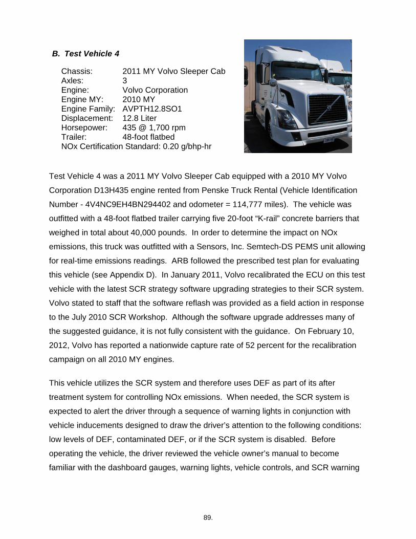
89.
B. Test Vehicle 4
Chassis: 2011 MY Volvo Sleeper Cab Axles: 3 Engine: Volvo Corporation Engine MY: 2010 MY Engine Family: AVPTH12.8SO1 Displacement: 12.8 Liter Horsepower: 435 @ 1,700 rpm Trailer: 48-foot flatbed NOx Certification Standard: 0.20 g/bhp-hr
Test Vehicle 4 was a 2011 MY Volvo Sleeper Cab equipped with a 2010 MY Volvo
Corporation D13H435 engine rented from Penske Truck Rental (Vehicle Identification
Number - 4V4NC9EH4BN294402 and odometer = 114,777 miles). The vehicle was
outfitted with a 48-foot flatbed trailer carrying five 20-foot “K-rail” concrete barriers that
weighed in total about 40,000 pounds. In order to determine the impact on NOx
emissions, this truck was outfitted with a Sensors, Inc. Semtech-DS PEMS unit allowing
for real-time emissions readings. ARB followed the prescribed test plan for evaluating
this vehicle (see Appendix D). In January 2011, Volvo recalibrated the ECU on this test
vehicle with the latest SCR strategy software upgrading strategies to their SCR system.
Volvo stated to staff that the software reflash was provided as a field action in response
to the July 2010 SCR Workshop. Although the software upgrade addresses many of
the suggested guidance, it is not fully consistent with the guidance. On February 10,
2012, Volvo has reported a nationwide capture rate of 52 percent for the recalibration
campaign on all 2010 MY engines.
This vehicle utilizes the SCR system and therefore uses DEF as part of its after
treatment system for controlling NOx emissions. When needed, the SCR system is
expected to alert the driver through a sequence of warning lights in conjunction with
vehicle inducements designed to draw the driver’s attention to the following conditions:
low levels of DEF, contaminated DEF, or if the SCR system is disabled. Before
operating the vehicle, the driver reviewed the vehicle owner’s manual to become
familiar with the dashboard gauges, warning lights, vehicle controls, and SCR warning

90.
system. Figure Volvo-1 displays the various driver warning lights used when the SCR
system requires attention.
Figure Volvo-1: Volvo’s SCR System Driver Warning Lights/Information
a) Vehicle 4 - Baseline Testing
Staff operated the “as received” 2011 MY Volvo over the designated test route while
sampling the vehicle’s exhaust to establish a baseline profile. A PEMS unit was
attached to the weight laden (five concrete K-rails) 48-foot flatbed trailer (see Figure
Volvo-2).

91.
Figure Volvo-2: Portable Emissions Monitoring System and K-Rails
The baseline portion of this test program represents the average typical emissions the
vehicle generates under normal vehicle operation. Staff began this test cycle with
114,806 miles on the odometer, adding 61 gallons of fuel at 115,128 miles, and over the
course of three days accumulated 577 miles (odometer = 115,383 miles). The daily
baseline emissions are represented in Figure Volvo-3 below.

92.
Figure Volvo-3: Daily Baseline Emissions Data
Note: The PEMS values in this figure were measured values taken during this test program while the vehicle was operated under on-road conditions. The NTE NOx is the on-road measurement of NOx emissions that requires specific engine operation and other criterion for attaining this measurement. The NOx certification emission standard of 0.20 g/bhp-hr requires emission measurements under laboratory conditions. This standard, in addition to the NTE standard of 0.30 g/bhp-hr and the NTE + 0.15 g/bhp-hr measurement allowance, was provided for general reference only. The PEMS unit used for this operation meets the U.S. EPA requirements per 40 CFR 1065.
This engine was certified to a 0.30 g/bhp-hr NTE standard with a measurement
allowance of 0.15 g/bhp-hr. As you can see the emissions for NTE NOx were within the
NTE allowance limit in all cases over multiple days. This vehicle exhibited the expected
NOx control based on its certification levels.
b) Vehicle 4 - DEF Depletion Cycle
The chart below, Figure Volvo-4, contains information from the Volvo Owner’s Manual
that came with the vehicle and was reproduced with Volvo’s permission. It displays the
stages of escalating driver warnings and alerts expected for the DEF Depletion Cycle.

93.
Figure Volvo-4: Volvo’s SCR Driver Warning Sequence for DEF Depletion
The engine was certified to 2010 standards and SCR requirements so we expected it to
be consistent with the 2010 MY Guidance. Step 1 is expected to occur when the DEF
level falls below 12 percent on the vehicle’s gauge initiating a DEF tank low level
indicator and a Driver Information Display (DID) message “DEF Low”. If no DEF is
added and the DEF Level Gauge reads 0%, Step 2 occurs initiating an audible chime
with a flashing DEF tank low level indicator, and the DID message changes to “DEF
Tank Near Empty, Engine in Derate, Add DEF”. Step 2 messages are expected to be
accompanied by an engine derate per Figure Volvo-4. Step 3a is interpreted to mean

94.
that the DEF tank falls to true empty, causing loss of DEF pump pressure, then the DID
changes to “DEF Tank Empty Refill DEF to Avoid 5 Mph Limit Engine in Derate”. When
Step 3a is reached, it is presumed the search for safe harbor would be initiated and
triggered by a refueling event of greater than 15 percent fuel capacity. Step 3b
indicates that the vehicle should experience a 5 mph severe inducement event when
the vehicle is refueled with the parking brake applied. However, as mentioned above,
the engine was upgraded with software that was supposed to make the vehicle more
consistent with the SCR warnings and inducements in the 2011+ MY Guidelines.
Day 1
In preparation for the DEF Depletion Cycle, staff adjusted the truck’s DEF level to
approximately 15 percent on the DEF Level Gauge (odometer = 115,383 miles).
After driving 140 miles, the first driver warning occurred (odometer = 115,523
miles) with the illumination of the DEF tank low level indicator light, the sounding of
an audible alert, and the DID displayed the message “DEF Low” (see Figure Volvo-
4, Step 1). The driver continued along the designated route and after driving 22
additional miles, the warnings extinguished (odometer=115,545 miles). Staff
operated the vehicle for another 31 miles in route to ARB’s El Monte facility and
observed the truck’s DEF level had dropped to 12 percent (odometer = 115,516
miles).
Day 2
Staff continued to drive the test route and after 50 miles, the vehicle began to
sound an audible alert every few minutes (odometer = 115,626 miles). According
to the owner’s manual, the DEF tank low level indicator light should have flashed;
however, based on the driver’s observations, the DEF tank low level indicator light
only illuminated but did not flash. Staff noted that the DEF Level Gauge indicated
that the DEF tank was near empty (i.e., the DEF gauge needle was reading slightly
above bottom of the ‘E’ mark on the DEF level gauge - see Figure Volvo-4, Step 2)
and drove for two additional hours noticing that the audible alerts continued to
sound periodically, approximately 20 times during this period. The DEF gauge

95.
level was at the bottom of the red mark on the DEF gauge level, which led staff to
assume that the DEF tank was empty. The driver then stopped to add 95 gallons
of diesel fuel (odometer = 115,705 miles). The audible alerts continued as staff
drove along the test route then returned to ARB’s El Monte facility
(odometer=115,768 miles).
Day 3
The following week, staff started the vehicle (odometer = 115,767 miles), the diesel
fuel tank was over ¾ full. Staff noted that the DEF tank low level indicator light was
illuminated and the DID displayed the message “Low DEF”. Next, two miles later,
audible alerts occurred with the message extinguishing. After driving 70 additional
miles, the driver noticed the audible alerts reoccurred (odometer = 115,839 miles).
After accumulating 194 miles, since starting the vehicle, staff returned to ARB’s El
Monte facility with no changes to the SCR driver warning alert system (odometer =
115,962 miles) and executed a key-off/key-on event but the vehicle did not
experience a 5 mph limited speed inducement. The driver observed that the DID
displayed the message “DEF Tank Empty, Refill DEF to Avoid 5 Mph Limit Engine
in Derate” warning (see Figure Volvo-4, Step 3a). The DEF light illuminated and
flashed after stopping the truck but the vehicle did not experience a 5 mph limited
speed inducement. After this trial, with no additional miles driven, staff shut down
the vehicle for the weekend.
Day 4
On Day 4 as staff attempted to drive the vehicle, it immediately experienced the 5 mph
severe inducement condition (odometer = 115,961 miles) the DEF light started to flash,
an audible alert beeped and the DID displayed the message "Vehicle Speed Limited to
5 Mph Add DEF" (see Figure Volvo-5) indicating that severe inducement sequence had
been reached. Staff shut down the vehicle and added two and a half gallons of DEF
and the DEF gauge level was at 15 percent capacity. Upon restart, the vehicle
triggered the SCR system into a “self-healing” reset and all the warning lights, chimes

96.
and messages were cleared. This SCR reset was designed to deactivate the
previously active SCR-related driver warnings and remove any vehicle SCR
inducements. Staff drove the vehicle and verified that the vehicle was back to normal
operation and returned to ARB’s El Monte facility (odometer = 115,962 miles)
concluding the DEF Depletion Cycle.
Figure Volvo-5: Volvo Driver Information Display Indicating 5 Mph Derate
The figure below represents the daily DEF Depletion Cycle emissions over various
driving segments and includes markers where certain SCR warnings and inducement
events occurred along the test route (see Figure Volvo-6). The events represented in
the figure include the first driver warning, and the presumed initiation of the vehicle’s
SCR strategy to seek the final inducement event based on the vehicle owner’s manual.
Note: the NTE NOx data is not shown in some of the traveled routes because some
ambient conditions were outside of the required NTE measurement zones.

97.
Figure Volvo-6: Daily DEF Depletion Cycle Emissions Data
Note: The PEMS values in this figure were measured values taken during this test program while the vehicle was operated under on-road conditions. The NTE NOx is the on-road measurement of NOx emissions that requires specific engine operation and other criterion for attaining this measurement. The NOx certification emission standard of 0.20 g/bhp-hr requires emission measurements under laboratory conditions. This standard, in addition to the NTE standard of 0.30 g/bhp-hr and the NTE + 0.15 g/bhp-hr measurement allowance, was provided for general reference only. The PEMS unit used for this operation meets the U.S. EPA requirements per 40 CFR 1065.
Despite DEF being depleted, as you can see, the Volvo truck maintained NOx control
throughout the entire testing sequence indicating the strategy used by Volvo was to
trigger warnings and inducements well ahead of NOx noncompliance which would likely
occur at true DEF depletion, unless significant other NOx control strategies were
employed.
Under the DEF Depletion Cycle, this vehicle performed as expected inducing driver
SCR visual/audible warnings that were preceded by escalating low DEF level

98.
inducements, including an engine power derate and ultimately a 5 mph limited vehicle
speed inducement. In addition, the NOx emissions measured under this cycle
performed within its NTE standard. All prescribed inducement strategies for this cycle
appeared to be consistent with the vehicle owner’s manual information, the 2010 MY
Guidance and the suggested 2011+ MY Guidelines, primarily by initiating warnings and
inducements well ahead of any noncompliance detection.
c) Vehicle 4 - DEF Contamination Cycle
The chart below, Figure Volvo-7, contains information from the Volvo Owner’s Manual
that came with the vehicle and was reproduced with Volvo’s permission. It displays the
stages of escalating driver warnings and alerts expected for the DEF Contamination
Cycle.
Figure Volvo-7: Volvo’s SCR Driver Warning Sequence for DEF Quality/Contamination

99.
Once poor quality DEF is detected, the amber check engine light is expected to
illuminate, accompanied by a DID message, “Engine Will Derate Soon”. After initial
detection plus 1 hour, if no remedy is sought, then the DID displays “SCR Malfunction
Engine in Derate Check SCR to Avoid 5 Mph Limit”. After initial detection plus four
hours, if no remedy, the search for final inducement is triggered by completing a 15
percent fuel refill, stopping the vehicle, performing a vehicle shutdown or a 20+ minute
idle, all accompanied by a new series of messages in the DID (see Figure Volvo-7 for
specific sequencing and messages).
Day 1
To begin the DEF Contamination Cycle, staff drained the DEF tank and added about
five gallons of deionized water prior to engine startup. The DEF level was about 25
percent full and the diesel fuel level was a little above the one half mark. After starting
the engine, staff observed that no SCR warning lights or alerts were active (odometer =
116,068 miles). As staff began to drive the vehicle, they also noticed the vehicle was
operating normally.
The SCR system triggered the first driver warnings and inducement within the first hour
of driving after accumulating 49 miles (odometer = 116,117 miles) with the illumination
of the amber Check Engine light, the DEF tank low level indicator light, a continuous
audible beep, and the DID showing the message "SCR Malfunction, Service SCR to
Avoid Engine Derate." Driving 15 more miles, the DID changed to “Derate Check
Engine Fault” and the audible alert had extinguished (odometer = 116,132 miles).
Approximately 45 minutes later (odometer = 116,167 miles), the DID changed again
showing “SCR Malfunction, Engine in Derate, Check SCR to Avoid 5 Mph Limit." The
previously observed SCR warning lights were still illuminated and the audible warning
alert began to beep continuously. Twelve miles later the driver noticed a loss of power
(odometer = 116,179 miles). Staff returned to ARB’s El Monte facility after
accumulating 199 miles for the day (odometer = 116,267 miles). Before shutting down
the vehicle, staff noted that the amber Check Engine light was illuminated and the DID
was displaying the message “SCR Malfunction, Engine in De-rate, Check SCR to Avoid

100.
5 Mph Limit." and the DEF gauge level had decreased to 1/5 of a tank. Staff shut off the
vehicle and ended testing for the day.
Day 2
Staff started the vehicle and immediately the amber Check Engine light and the DEF
tank low level indicator light were illuminated; the audible warning alert beeped
continuously; the particulate trap regeneration light was flashing; and the DID displayed
the message "Check Engine Fault & Service SCR, System 5 Mph Limit." Staff
attempted to drive the vehicle and immediately experienced the 5 mph severe
inducement condition (odometer = 116,267 miles). The drive time to reach the final
inducement since the first driver warning was triggered was approximately three hours
and 15 minutes and the vehicle was driven 150 miles. The vehicle was then shut off for
the day.
In preparation for the next test cycle, ARB staff removed the water from the DEF tank
and replaced it with approximately five gallons of quality DEF. ARB staff cleared codes
with a Volvo scan tool removing all SCR related alerts and messages (odometer =
116,267 miles). At this time, the vehicle required a diesel particulate filter (DPF)
regeneration which was carried out by staff as the vehicle was parked at ARB’s El
Monte facility. After completion of the DPF regeneration event, staff drove the vehicle
and noticed that the vehicle was still experiencing an engine power derate. Staff drove
the vehicle test route to try and clear the derate condition and after driving for
approximately 40 miles, staff observed that the vehicle power gradually went back to
normal. Staff returned to ARB’s El Monte facility and shut down the vehicle (odometer =
116,393 miles). The DEF Contamination Cycle was now complete.
The figure below, Figure Volvo-8, represents the daily DEF Contamination Cycle
emissions and includes markers where certain SCR warnings and inducement events
occurred along the test route. The events represented in the figure include the first
driver warning, the onset of the engine derate, and the presumed initiation of the
vehicle’s SCR strategy to seek the final inducement event.

101.
Figure Volvo-8: Daily DEF Contamination Cycle Emissions Data
Note: The PEMS values in this figure were measured values taken during this test program while the vehicle was operated under on-road conditions. The NTE NOx is the on-road measurement of NOx emissions that requires specific engine operation and other criterion for attaining this measurement. The NOx certification emission standard of 0.20 g/bhp-hr requires emission measurements under laboratory conditions. This standard, in addition to the NTE standard of 0.30 g/bhp-hr and the NTE + 0.15 g/bhp-hr measurement allowance, was provided for general reference only. The PEMS unit used for this operation meets the U.S. EPA requirements per 40 CFR 1065.
With water used in place of DEF, it can be seen that NOx control was lost almost
immediately as the residual DEF was depleted by the water and therefore most likely
initiated noncompliance detection within the first 49 miles (approximately one hour) of

102.
engine start up. NOx emissions averaged between 1.5 to 2.5 g/bhp-hr for the various
driving segments.
The DEF Contamination Cycle performed similar to the DEF Depletion Cycle, prompting
escalating SCR warnings/audible alerts and engine inducements including an engine
power derate and a severe inducement strategy limiting vehicle speed to 5 mph. The
ARB driver reported that the engine power derate was very noticeable when the truck
struggled to accelerate onto a freeway or negotiating moderate freeway upgrades. The
driver commented that these conditions would not be acceptable to a vehicle operator
for extended periods of driving. In regards to the vehicle emissions performance under
these cycles, the NOx emissions were well beyond the NOx NTE standard. When
water was used in place of DEF, the vehicle’s emissions results showed an immediate
loss of NOx control with the NOx NTE emission results emitting between 1.5 to 2.5
g/bhp-hr for the various driving segments. Overall, the initial detection occurred within
one hour by triggering driver warnings and searched for final inducement within four
hours after detection. All prescribed inducement strategies appeared to be consistent
with the vehicle owner’s manual information and the 2010 MY Guidance. Additionally,
the software upgrades apparently made them consistent with the SCR 2011+ MY
Guidelines.
d) Vehicle 4 - DEF System Tampering Cycle
The chart below, Figure Volvo-9, contains information from the Volvo Owner’s Manual
that came with the vehicle and was reproduced with Volvo’s permission. It displays the
stages of escalating driver warnings and alerts expected for the DEF System Tampering
Cycle.

103.
Figure Volvo-9: Volvo’s SCR Driver Warning Sequence for SCR Tampering
Once the tampering fault is detected, the amber Check Engine Light is expected to
illuminate accompanied by a DID message, “SCR System Fault, Engine Will Derate
Soon”. After the initial detection and a second drive cycle, and no remedy is sought, the
malfunction indicator light is illuminated and the DID continues to display the same
message. After driving for an hour with the same active warnings, the DID will change
its message to “SCR System Fault Engine in Derate”. After continuing to drive for four
more hours with the active warnings still illuminated, the DID will display the message
“SCR System Fault Repair needed to Avoid 5 Mph Limit”. If the warnings are ignored,
the vehicle should display the message on the DID “Repair SCR System Fault 5 Mph
Limit” and trigger the 5 mph severe inducement when a safe harbor is reached (i.e., a
safe harbor would occur when the vehicle’s fuel level is increased by 15 percent fuel, or
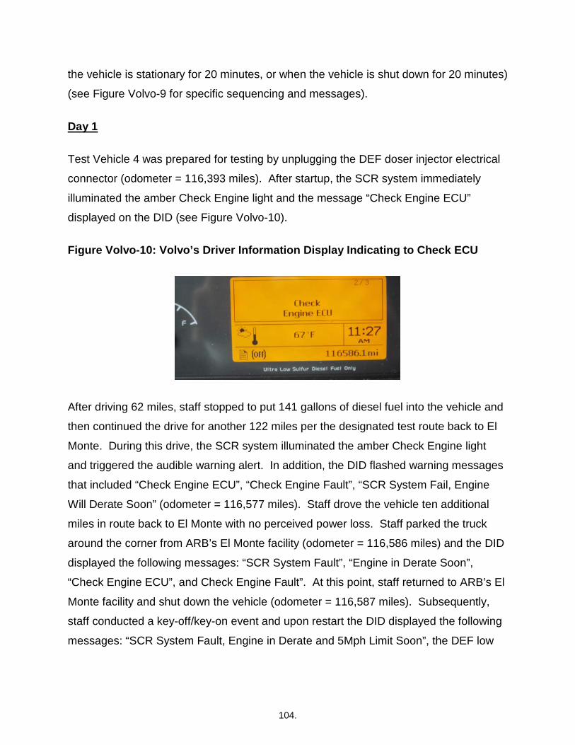
104.
the vehicle is stationary for 20 minutes, or when the vehicle is shut down for 20 minutes)
(see Figure Volvo-9 for specific sequencing and messages).
Day 1
Test Vehicle 4 was prepared for testing by unplugging the DEF doser injector electrical
connector (odometer = 116,393 miles). After startup, the SCR system immediately
illuminated the amber Check Engine light and the message “Check Engine ECU”
displayed on the DID (see Figure Volvo-10).
Figure Volvo-10: Volvo’s Driver Information Display Indicating to Check ECU
After driving 62 miles, staff stopped to put 141 gallons of diesel fuel into the vehicle and
then continued the drive for another 122 miles per the designated test route back to El
Monte. During this drive, the SCR system illuminated the amber Check Engine light
and triggered the audible warning alert. In addition, the DID flashed warning messages
that included “Check Engine ECU”, “Check Engine Fault”, “SCR System Fail, Engine
Will Derate Soon” (odometer = 116,577 miles). Staff drove the vehicle ten additional
miles in route back to El Monte with no perceived power loss. Staff parked the truck
around the corner from ARB’s El Monte facility (odometer = 116,586 miles) and the DID
displayed the following messages: “SCR System Fault”, “Engine in Derate Soon”,
“Check Engine ECU”, and Check Engine Fault”. At this point, staff returned to ARB’s El
Monte facility and shut down the vehicle (odometer = 116,587 miles). Subsequently,
staff conducted a key-off/key-on event and upon restart the DID displayed the following
messages: “SCR System Fault, Engine in Derate and 5Mph Limit Soon”, the DEF low

105.
level indicator light came on and the vehicle went into a 5 mph derate. (see Figure
Volvo-11 below).
Figure Volvo-11: Volvo Driver Information Display Indicating 5 Mph Derate
Day 2
With the DEF doser injector still disconnected, staff again tried to drive the vehicle the
following morning and confirmed that the vehicle was still limited to 5 mph. With the
SCR system limiting the vehicle speed to 5 mph, the final step of the DEF System
Tampering Cycle had occurred. The drive time to reach the final inducement since the
first driver warning was triggered was approximately three hours and 55 minutes and
194 miles were traveled. Staff reconnected the DEF doser injector and all SCR related
warning alerts and messages immediately extinguished. The driver elected to go into
the next test cycle because no message displayed stating the vehicle was under a
power loss condition. The DEF System Tampering Cycle was now complete.
The figure below represents the daily DEF System Tampering Cycle emissions and
includes markers where certain SCR inducement events occurred along the test route
(see Figure Volvo-12 below). The events represented in the figure include the first
driver warning and the initiation of the vehicle’s SCR strategy to seek the final
inducement event.

106.
Figure Volvo-12: Daily DEF System Tampering Cycle Emissions Data
Note: The PEMS values in this figure were measured values taken during this test program while the vehicle was operated under on-road conditions. The NTE NOx is the on-road measurement of NOx emissions that requires specific engine operation and other criterion for attaining this measurement. The NOx certification emission standard of 0.20 g/bhp-hr requires emission measurements under laboratory conditions. This standard, in addition to the NTE standard of 0.30 g/bhp-hr and the NTE + 0.15 g/bhp-hr measurement allowance, was provided for general reference only. The PEMS unit used for this operation meets the U.S. EPA requirements per 40 CFR 1065.
The DEF System Tampering Cycle performed similar to the DEF Contamination Cycle,
prompting escalating SCR warnings/audible alerts and a severe engine inducement
strategy limiting vehicle speed to 5 mph. However, no engine derate was noticed by the
driver during any part of the test. In regards to the vehicle emissions performance
under these cycles, the NOx emissions were well beyond the NOx NTE standard.
Overall, the initial detection occurred within 1 hour by triggering driver warnings and
reached the final inducement within four hours after detection. All prescribed

107.
inducement strategies appeared to be consistent with the vehicle owner’s manual
information, the 2010 MY Guidance and the software upgrades apparently made them
consistent with the SCR 2011+ MY Guidelines from the July 2010 SCR Workshop as
well.
e) Vehicle 4 - DEF Dilution Cycles
As with the DDC truck, staff decided to check three different blended mixtures of DEF,
with 25 percent water (resulting urea concentration in mixture of ~24.4 percent), 50
percent water (resulting urea concentration in mixture of ~16.2 percent), and 75 percent
water (resulting urea concentration in mixture of ~8.1% percent) to determine the
percentage of diluted DEF that would likely result in increased NOx emissions. Staff
operated the vehicle using each of the different DEF diluted concentrations to determine
the DEF threshold for the SCR system to trigger driver warnings and SCR inducements
while measuring the emissions with each dilution cycle. This cycle was not intended to
drive these vehicles to trigger the 5 mph final inducement event, only to determine if
different diluted blends of DEF would cause the SCR inducement system to activate.
(1) DEF Diluted with 25 Percent Water
Day 1
To begin the DEF Dilution Cycle, staff drained the DEF tank and added five gallons of a
DEF/water blend (concentration verified with a DEF Refractometer) that included a
blend of quality DEF and deionized water. The DEF gauge level was filled to one fifth of
capacity and the diesel fuel gauge level was showing a little over three quarters of tank
full. Upon engine start up, staff observed that no SCR related warning lights or audible
alerts were present (odometer = 116,587 miles). As staff drove the vehicle, they
confirmed the vehicle was operating normally.
The SCR system triggered the first driver warning for diluted DEF after driving 107 miles
(odometer = 116,694 miles) with the illumination of the amber Check Engine light;
triggered the audible warning alert; and the DID displayed the messages, "Service SCR

108.
System before Refueling, to Avoid 5 Mph Derate" and "Check Engine Fault."
Approximately 10 minutes later, the driver experienced an engine power loss. Staff
returned to ARB’s El Monte facility after accumulating 192 miles for the day with no
additional SCR warnings or messages (odometer = 116,779 miles). Since running the
dilution cycle was an effort to determine at what percentage dilution the SCR system
could detect a diluted DEF solution blend, staff chose to discontinue testing and move
on to the next dilution cycle with the DEF gauge level at 15 percent.
Day 2
To conclude the 25 percent Diluted DEF Cycle, ARB staff added 82 gallons of diesel
fuel, removed the blended DEF/water mixture and filled the DEF tank with
approximately five gallons of quality DEF. ARB staff cleared codes with a Volvo scan
tool, removing all SCR related alerts and messages. Staff then drove the vehicle but
noticed that the vehicle was initially still experiencing an engine power derate.
However, after driving approximately 40 miles, staff observed that the vehicle power
gradually went back to normal. Staff returned to ARB’s El Monte facility and shut down
the vehicle (odometer = 116,905 miles).
The figure below represents the daily 25 percent Diluted DEF Cycle emissions and
includes markers where certain SCR warning and inducement events occurred along
the test route (see Figure Volvo-13 below). The events represented in the figure include
the first driver warning and the onset of the engine derate event.

109.
Figure Volvo-13: Daily DEF Dilution Cycle (25 Percent Water) Emissions Data
Note: The PEMS values in this figure were measured values taken during this test program while the vehicle was operated under on-road conditions. The NTE NOx is the on-road measurement of NOx emissions that requires specific engine operation and other criterion for attaining this measurement. The NOx certification emission standard of 0.20 g/bhp-hr requires emission measurements under laboratory conditions. This standard, in addition to the NTE standard of 0.30 g/bhp-hr and the NTE + 0.15 g/bhp-hr measurement allowance, was provided for general reference only. The PEMS unit used for this operation meets the U.S. EPA requirements per 40 CFR 1065.
As shown in Figure Volvo-13, the vehicle maintained good NOx control initially during
the first drive segment most likely before the diluted DEF totally infiltrated the system or

110.
the system was no longer able to dose sufficient concentration of urea despite
increasing dosing amounts. Sometime between mile 30 and 107 of the drive the NOx
emissions obviously increased triggering the poor quality DEF detection and first driver
warning at the 107 mile point. Once NOx control was lost, emissions ranged from 1.0 to
1.5 g/bhp-hr on average. Some NTE points when averaged over a specific drive
segment were slightly higher.
(2) DEF Diluted with 50 Percent Water
Day 1
For the 50 percent DEF Dilution Cycle, staff drained the DEF tank and added about five
gallons of a DEF/water blend (concentration verified with a DEF Refractometer). The
DEF gauge level was at 20 percent at the start of this cycle. The test route began with`
the odometer at 116,905 miles. The SCR system triggered the first driver warning and
inducement for diluted DEF after driving 47 miles (odometer = 116,952 miles) with the
illumination of the amber Check Engine light and the sounding of an audible warning
alert. The DID displayed the messages, "Service SCR System before Refueling to
Avoid 5 Mph Derate" and "Check Engine Fault." In addition to the visual and audio
warnings, the driver experienced an engine power loss inducement. Staff returned to
ARB’s El Monte facility after accumulating 193 miles for the day with no additional SCR
warnings or messages (odometer = 117,098 miles).
Day 2
To conclude the 50 percent DEF Dilution Cycle, ARB staff added 61 gallons of diesel
fuel, removed the blended DEF/water mixture and filled the DEF tank with
approximately five gallons of quality DEF. ARB staff cleared codes with a Volvo scan
tool removing all SCR related alerts and messages. After driving the vehicle for 40
miles, the engine power derate appeared to be gone and vehicle returned back to
normal power. Staff continued to drive the vehicle for a few extra miles to verify normal

111.
vehicle operation and then returned to ARB’s El Monte facility (odometer = 117,226
miles).
The figure below represents the daily 50 percent DEF Dilution Cycle (50 Percent Water)
emissions and includes markers where certain SCR warning and inducement events
occurred along the test route (see Figure Volvo-14 below). The events represented in
the figure include the first driver warning and the onset of the engine derate event.
Figure Volvo-14: Daily DEF Dilution Cycle (50 Percent Water) Emissions Data
Note: The PEMS values in this figure were measured values taken during this test program while the vehicle was operated under on-road conditions. The NTE NOx is the on-road measurement of NOx emissions that requires specific engine operation and other criterion for attaining this measurement. The NOx certification emission standard of 0.20 g/bhp-hr requires emission measurements under laboratory conditions. This standard, in addition to the NTE

112.
standard of 0.30 g/bhp-hr and the NTE + 0.15 g/bhp-hr measurement allowance, was provided for general reference only. The PEMS unit used for this operation meets the U.S. EPA requirements per 40 CFR 1065.
The NOx emissions for the 50 percent DEF Dilution Cycle increased immediately in
response to poor quality DEF indicating the vehicle was not able to adjust by increasing
dosing amount or other NOx control means. The vehicle detected the loss of NOx
control and triggered the first warning and inducement at the 47 mile test route point
with emissions averaging around 1.3 g/bhp-hr NOx within the second leg of the test
route. Overall, NOx emissions varied from approximately 1.0 to 2.1 g/bhp-hr NOx under
the 50% DEF Dilution Cycle.
(3) DEF Diluted with 75 Percent Water
Day 1
Continuing with the third and final 75 percent DEF Dilution Cycle, staff drained the DEF
tank and added a DEF/water blend (concentration verified with a DEF Refractometer).
The odometer was at 117,226 miles as the test route resumed. The SCR system
triggered the first driver warning and inducement for diluted DEF after driving 39 miles
(odometer = 117,265 miles) with the DID displaying the messages, "Service SCR
System before Refueling to Avoid 5 Mph Derate" and "Check Engine Fault." In addition,
the driver experienced an engine power loss. Approximately 130 miles later, the SCR
system illuminated the amber Check Engine light with no additional warning messages.
Staff returned to ARB’s El Monte facility after accumulating 192 miles for the day with no
additional SCR warnings or messages (odometer = 117,418 miles).
Day 2
With this last evaluation complete, staff prepared the vehicle for its return to Penske
Truck Rental. ARB staff added 59 gallons of diesel fuel, removed the DEF diluted
mixture, filled the DEF tank with five gallons of quality DEF, and cleared codes with a
Volvo scan tool removing all SCR related alerts and messages. After all these actions
were completed, staff drove the vehicle for 40 miles when the engine power derate
extinguished returning the vehicle power back to normal. Staff continued to drive the

113.
vehicle to verify normal vehicle operation and returned to ARB’s El Monte facility
(odometer = 117,542 miles). The following day staff added 8.7 gallons of diesel fuel and
returned this vehicle to Penske Truck Rental.
The figure below represents the daily 75 percent DEF Dilution Cycle (75 Percent Water)
emissions and includes markers where certain SCR warning and inducement events
occurred along the test route (see Figure Volvo-15 below). The events represented in
the figure include the first driver warning and the onset of the engine derate event.
In conclusion, the results showed the NOx emissions increased within the first short
driving segment. The triggering of the first driver warning and inducement occurred at
the 39 miles driving route marker indicating the vehicle had detected poor quality DEF.
The NOx emissions varied from 1.6 to roughly 2.3 g/bhp-hr NOx during the testing
route.

114.
Figure Volvo-15: Daily DEF Dilution Cycle (75 Percent Water) Emissions Data
Note: The PEMS values in this figure were measured values taken during this test program while the vehicle was operated under on-road conditions. The NTE NOx is the on-road measurement of NOx emissions that requires specific engine operation and other criterion for attaining this measurement. The NOx certification emission standard of 0.20 g/bhp-hr requires emission measurements under laboratory conditions. This standard, in addition to the NTE standard of 0.30 g/bhp-hr and the NTE + 0.15 g/bhp-hr measurement allowance, was provided for general reference only. The PEMS unit used for this operation meets the U.S. EPA requirements per 40 CFR 1065.
The DEF Dilution Cycles were conducted to determine if a diluted DEF tank mixture
would cause SCR driver warnings and inducements to employ along with increasing
NOx emissions. Overall, the results disclosed that diluting the DEF tank (in all three

115.
diluted cycle evaluations) with water caused the SCR driver warnings and inducements
to engage and caused NOx emissions to increase well beyond the NTE limit. As the
amount of water in the DEF increased, so did the NOx emissions, as well as diminishing
the time to trigger warnings and inducements. The 25 percent DEF Dilution Cycle
initially maintained NOx control early in the test route (first 29 miles), but as the loss of
NOx control was experienced somewhere between mileage points 30 to 62, and verified
at mile 107, the first driver warning was initiated followed by the first driver inducement.
The last two dilution cycles evaluated (DEF tank diluted with 50 and 75 percent water)
obviously lost NOx control sooner than the 25 percent DEF Dilution Cycle and triggered
their warnings and inducements at the 47 and 39 mile (roughly one hour or less) test
route markers, respectively. The 2011+ MY Guidelines’ goal is to detect noncompliance
within an hour and notify the operatory immediately. The pattern of test results indicate
that the loss of NOx control occurs sooner with higher concentrations of diluted DEF
and so did the warning and inducements. The 50 percent and 75 percent DEF Dilution
Cycles responses were clearly consistent with the 2011+ MY Guidelines since they
detected a noncompliance within an hour and notifying the operator immediately, while
the 25 percent DEF Dilution Cycle result was inconclusive due to a more gradual
increase in NOx emissions as mileage was accumulated and the actual noncompliance
mileage could not be pinpointed.
f) Vehicle 4 - Emissions Measurements
Test Vehicle 4 was outfitted with a PEMS unit which measured the vehicle’s emissions
as the vehicle was operated over the designated test route. The vehicle’s average
baseline emissions were compared to average emissions from the DEF Depletion, DEF
Contamination, DEF System Tampering and the DEF Dilution Cycles. Figure Volvo-16
(see below) is a summary of the average NOx emissions measured for each of these
test cycles. It should be noted that staff utilized qualifying NTE zone emission
measurements to compare the emission results for each test cycle. The certification
standard is also shown on the chart but the test requirements to conduct a certification
type test require an engine dynamometer under laboratory conditions and cannot be

116.
directly compared to the in-use PEMS measurements. This standard was only included
on the chart for informational purposes.
The average Baseline Cycle NTE NOx emissions of 0.20 g/bhp-hr were easily within the
engine’s NTE NOx standards of 0.3 g/bhp-hr without consideration of the NTE
measurement allowance. The Depletion Cycle PEMS measurements were taken over
three days from the time the vehicle began the Depletion Cycle until the vehicle went
into a 5 mph limited speed derate. The overall average NOx emissions as DEF
depleted to empty were 0.18 g/bhp-hr; therefore, it is presumed the vehicle had enough
residual DEF or other means to maintain control of NOx emission levels leading up to
the vehicle experiencing a 5 mph limited speed event.
The average NOx emissions for the DEF Contamination and DEF System Tampering
Cycles were approximately seven times higher than the baseline NTE results with NOx
emissions slightly above the 2.0 g/bhp-hr level. As for the DEF Dilution Cycles, the NOx
emissions results were about four to seven times higher than the baseline NTE NOx
emission levels dependent on the dilution level. The average NOx emissions ranged
from 1.18 to 1.90 g/bhp-hr over the 25 percent to 75 percent DEF Dilution cycles,
respectively. The observation indicates that Volvo’s SCR system could detect poor
quality diluted DEF and adjusted DEF dosing and/or other NOx control mechanisms to
control NOx, but ultimately reached its ability to control NOx emissions triggering the
SCR system inducement strategy.

117.
Figure Volvo-16: Vehicle 4: NOx Emission Data Summary
Note: The PEMS values in this figure are the average NOx NTE emissions taken during this test program while the vehicle was operated under on-road conditions. The NOx certification emission standard of 0.20 g/bhp-hr requires emission measurements under laboratory conditions. This standard, in addition to the NTE standard of 0.30 g/bhp-hr and the NTE + 0.15 g/bhp-hr measurement allowance, was provided for general reference. The PEMS unit used for this operation meets the U.S. EPA requirements per 40 CFR 1065.
g) Vehicle 4 - Inducement Test Summary
ARB staff operated Test Vehicle 4 under various test cycles comparing the vehicle’s
SCR-related driver warnings and inducements to those supplied in the vehicle owner’s
manual and its consistency with the 2010 MY Guidance and/or 2011+ MY Guidelines. It
was expected that it would be consistent with the 2010 MY Guidance since the engine
was certified to 2010 standards and SCR requirements. ARB staff checked the driver
warnings and inducements under the following cycles: DEF Depletion Cycle, DEF
Contamination Cycle, DEF System Tampering Cycle, and DEF Dilution Cycles. Under

118.
the DEF Depletion Cycle, this vehicle performed as expected inducing driver SCR
visual/audible warnings that were preceded by escalating low DEF level inducements,
including an engine power derate and ultimately a 5 mph limited vehicle speed
inducement.
With the exception of one minor difference, the SCR warnings and inducement
strategies were consistent with the vehicle owner’s manual, the 2010 MY Guidance and
the 2011+ MY Guidelines for the DEF Contamination and DEF Tampering Cycles.
During the DEF Contamination Cycle the vehicle inducements were effective in that the
engine did experience a power derate and the driver noticed a power loss during the
test cycle; however, the MIL wasn’t illuminated as indicated in the vehicle owner’s
manual. The driver would not tolerate the inducement conditions while on his daily
routes as it would be unbearable to be limited to a 5 mph speed limit. During the DEF
System Tampering Cycle the vehicle also performed consistently in that the SCR
related inducements occurred within the one hour and four hour time periods as
described in the vehicle owner’s manual.
At the conclusion of testing, the ARB driver stated that the SCR system’s warning lights
and audible alerts were effective in obtaining his attention while conducting the driving
events for each test cycle. Furthermore, the occurrence of engine derates would make
it difficult for the average driver to complete his daily routes. Lastly, truck drivers would
be discouraged from tampering with their vehicles’ SCR systems and/or allowing the
DEF to run empty to avoid resulting problems, such as undergoing a 5 mph severe
inducement.

119.
C. Test Vehicle 5
Chassis: 2012 MY International Pro Star Axles: 3 Engine: Maxxforce 13 Engine MY: 2011 MY Engine Family: BNVXH07570GB Displacement: 12.4 Liter Horsepower: 430 HP @ 1700 RPM Trailer: 48-foot flatbed NOx Certification FEL: 0.50 g/bhp-hr
ARB staff procured a 2012 MY International Pro Star truck (Vehicle Identification
Number - 1HSDHSJR8CJ565976). This vehicle was a three axle tractor equipped with
the 2011 MY Navistar Maxxforce 13 engine rented from Idealease, a local commercial
truck rental company. When ARB took possession of the vehicle from Idealease, the
odometer showed 35,608 miles. The vehicle was outfitted with a 48-foot flatbed trailer
loaded with five 20-foot “K-rail” concrete barriers that weighed in total about 40,000
pounds. Test plan 1Q1102 was used for this test evaluation (see Appendix D). In order
to determine the impact on NOx emissions, this truck was outfitted with a Sensors, Inc.
Semtech-DS PEMS unit allowing for real-time emissions readings. Because this vehicle
did not utilize a SCR system for NOx control, the evaluation cycles were changed to
accommodate the NOx control technology of this truck. The evaluation cycles used for
this vehicle included the Baseline Test Cycle, the Lean Cruise Cycles 1 and 2, and the
Restricted Exhaust Gas Recirculation (EGR) Cycle. The vehicle instrument panel was
equipped with an amber Check Engine light or MIL to alert the operator of a
malfunctioning engine control system (see Figure Navistar-1).

120.
Figure Navistar-1: Navistar Instrument Panel - Check Engine Light
a) Vehicle 5 - Baseline Test Cycle
The baseline portion of this test program consisted of operating the vehicle over normal
vehicle operation on prescribed test routes while measuring NOx emissions. Testing
began with the diesel fuel tank filled to about 80 percent of its capacity and the
odometer reading 35,638 miles.
Day 1
Staff drove the vehicle over the designated test route for 195 miles (odometer = 35,833
miles) collecting baseline exhaust emissions. The vehicle was observed to operate
normally with no notification of any engine problems or issues.
Day 2
Staff drove the vehicle over the designated test route for 193 miles (odometer = 36,026
miles) collecting baseline exhaust emissions. Again, the driver noted there were no
observations of any engine problems or issues.

121.
Day 3
Staff drove the vehicle over the designated test route for 193 miles (odometer = 36,219
miles) collecting baseline exhaust emissions and concluded the baseline test route with
no observations of any engine problems or issues.
The total miles driven over the three days was 581 miles, establishing the average
driving segment baseline NOx emissions data (odometer = 36,219 miles).
Figure Navistar-2: Navistar Baseline Test Cycle
Note: The PEMS values in this figure were measured values taken during this test program while the vehicle was operated under on-road conditions. The NTE NOx is the on-road measurement of NOx emissions that requires specific engine operation and other criterion for attaining this measurement. The NOx family emission limit of 0.50 g/bhp-hr requires emission measurements under laboratory conditions. This standard, in addition to the NTE standard of 0.75 g/bhp-hr and the NTE + 0.15 g/bhp-hr measurement allowance, was provided for general reference only. The PEMS unit used for this operation meets the U.S. EPA requirements per 40 CFR 1065.

122.
The average baseline NOx emissions divided into driving segments are graphed in
Figure Navistar-2. The standards at which the Navistar engine was certified are
included, as well, for comparison to the PEMS results. It should be noted that the FEL
standard of 0.50 g/bhp-hr is listed only for reference since a true direct comparison can
only be made in the laboratory on an engine dynamometer. However, the NTE
standard is expected to be met with the 0.15 allowance applied once non-qualifying
data is removed per the In-Use Compliance regulations. As can be seen in the graph,
this engine met the NTE standard plus measurement allowance of 0.90 g/bhp-hr over all
qualifying NTE segments.
b) Vehicle 5 - Lean Cruise Cycle 1
The Lean Cruise Cycle was developed to identify if a manufacturer calibrated their
engine to achieve better fuel economy when maintaining steady state freeway speeds.
A lean cruise calibration will cause the air/fuel ratio to change to a lean condition when
the vehicle has come to a steady cruise operation where significant power is not
necessary to maintain the vehicle speed (e.g., over a stretch of road where minimal
throttle movement is required to maintain a steady speed). This type of calibration
provides increased fuel economy but with the risk of increased NOx emissions and
considered a defeat device that led to a consent decree with several heavy-duty
manufacturers in the late nineties for unscrupulous business practices. ARB utilized
this test cycle to determine if an engine utilizing EGR as its primary NOx control shows
a significant increase in NOx emissions when driven at steady speeds over a
reasonably flat test route. Staff identified a seven mile stretch of road that was nine
miles from the Hesperia turnaround point for this test cycle (see Figure Navistar-3). Staff
chose this route because the road looked reasonably flat allowing for vehicle operation
with minimal throttle movement. However, staff later determined that the road had too
many elevation changes (creating a rolling affect) which made it difficult to modulate the
vehicle’s speed to 55 mph. Although the road did not offer the best surface for
conducting this test cycle (see Figure Navistar- 4), staff agreed to complete the test
cycle and then repeat this operation on a different highway as discussed later in the
report (see Lean Cruise Cycle 2).

123.
Figure Navistar-3: Navistar Lean Cruise Cycle 1 Drive Route

124.
Figure Navistar-4: Uneven Road Between Johnson Rd and Monte Vista Rd
Day 1
The Lean Cruise Cycle 1 was initiated with an odometer reading of 36,219 miles. The
driver completed three round trips over the designated test route; and while using the
accelerator pedal, attempted to maintain an average speed of 55 mph. This was
followed by two additional laps while utilizing the vehicle’s cruise control set to 55 mph.
Only two round trips were conducted with the cruise control on because the ambient air
was cold which caused the air lines to the trailer to stiffen. While attempting to make a
U-turn on the drive route the air lines were not flexible and disengaged on two
occasions causing the trailer brakes to lock and preventing the driver from moving the
truck. Initially, the driver did not immediately know why the truck would not move and
noticed that traffic had to stop because the vehicle was blocking the road. After finally
discovering the problem, the driver reconnected the air lines and moved the truck out of
traffic. Due to the safety issues of losing the air lines to the trailer while making a U-
turn, the driver decided to terminate the last portion of this test cycle. Overall, the

125.
vehicle drove well with no associated problems and was operated for 222 miles under
this test cycle (odometer = 36,441 miles).
The results of the Lean Cruise Cycle 1 are graphed in Figure Navistar-5 with the FEL,
NTE standards and the in-use measurement allowance for NTE. The instruments
detected that the average NTE NOx emissions produced with the driver in control of the
vehicle speed was 0.708 g/bhp-hr and increased to 0.801 g/bhp-hr when the vehicle
cruise control was set. As can be seen in the graph, this engine met the NTE standard
plus measurement allowance of 0.90 g/bhp-hr over all qualifying NTE segments. It is
interesting to note that four of the five segments driven from Johnson Road to Monte
Vista Road had no qualifying NTE points obtained. Part of this problem may be related
to the uneven road surface that did not allow for steady throttle settings as discussed
earlier (see Figure Navistar- 4).

126.
Figure Navistar-5: Lean Cruise Cycle 1
Note: The PEMS values in this figure were measured values taken during this test program while the vehicle was operated under on-road conditions. The NTE NOx is the on-road measurement of NOx emissions that requires specific engine operation and other criterion for attaining this measurement. The NOx family emission limit of 0.50 g/bhp-hr requires emission measurements under laboratory conditions. This standard, in addition to the NTE standard of 0.75 g/bhp-hr and the NTE + 0.15 g/bhp-hr measurement allowance, was provided for general reference only. The PEMS unit used for this operation meets the U.S. EPA requirements per 40 CFR 1065.
c) Vehicle 5 - Restricted EGR Cycle
For the Restricted EGR Cycle staff wanted to investigate what would occur if EGR, used
as the vehicle’s primary NOx control device, were modified. In the past, blocking the
EGR created engine enhancements where the engine had improved power and fuel
economy but caused NOx emissions to drastically increase. Staff set out to simulate
the effects caused by a plugged EGR cooler or when an EGR valve becomes stuck in
the closed position by placing an aluminum plate between the EGR cooler and the EGR
transfer pipes (See Figure Navistar-6) to see if there would be any engine enhancement
benefits to a current technology engine.

127.
Figure Navistar-6: Restricted Exhaust Flow to EGR
Day 1
The Restricted EGR Cycle began with the odometer at 36,441 miles. As the test route
commenced, the driver observed that the vehicle appeared to have sufficient power in
low gears at engine revolutions per minute (rpm) levels above 1,400 rpm; however, the
vehicle began to experience a surging condition when the driver increased to vehicle
speeds of 55 mph and in 10th gear. The surging continued throughout the test cycle
and a loss of power at lower engine rpm’s was noticed. Staff refueled and filled the tank
with 106.9 gallons of diesel fuel (odometer = 36,571 miles) and continued the test route.
After driving two more miles (odometer = 36,573 miles) the engine MIL illuminated and
the driver continued to experience loss of power and the surging condition throughout
the test route. A total of 193 miles (odometer = 36,634 miles) was accumulated at the
end of Day 1.
Day 2
Before beginning Day 2’s drive, staff utilized a PC based Navistar specific diagnostic
scan tool (loaned to ARB from Navistar) to check for engine trouble codes. The Engine
Manufacturer Diagnostic (EMD) trouble codes were interrogated and an active code for

128.
EGR Low Flow Rate Detected was present. The driver ignored the trouble codes and
MIL and continued to operate the vehicle over the test route on Day 2 accumulating 194
more miles (odometer = 36,828 miles). This concluded the Restricted EGR Cycle.
Day 3
Staff removed the EGR block off plates and the vehicle was driven for an additional 162
miles (odometer = 36,990 miles) to allow for self-healing of the EGR system. During the
drive, the driver performed three key-off/key-on events with the third event extinguishing
the illuminated MIL. Once the self-healing had taken place, the diagnostic trouble
codes were cleared with Navistar’s diagnostic scan tool.
The NOx emission results of the Restricted EGR Cycle are shown in Figure Navistar-7.
Keep in mind due to the poor operating conditions of the vehicle during this driving
cycle, a driver is not likely to operate the vehicle for very long before seeking repair.
The average segment NOx emissions were 8.29 g/bhp-hr and 9.2 times the NTE
standard with the NTE allowance of 0.90 g/bhp-hr.

129.
Figure Navistar-7: Restricted EGR Cycle
Note: The PEMS values in this figure were measured values taken during this test program while the vehicle was operated under on-road conditions. The NTE NOx is the on-road measurement of NOx emissions that requires specific engine operation and other criterion for attaining this measurement. The NOx family emission limit of 0.50 g/bhp-hr requires emission measurements under laboratory conditions. This standard, in addition to the NTE standard of 0.75 g/bhp-hr and the NTE + 0.15 g/bhp-hr measurement allowance, was provided for general reference only. The PEMS unit used for this operation meets the U.S. EPA requirements per 40 CFR 1065.
d) Vehicle 5 - Lean Cruise Cycle 2
The Lean Cruise Cycle 1 was performed on a section of road that was not ideal for this
type of testing. The road had frequent quick elevation changes that would require the
driver to constantly adjust the throttle and ultimately would result in varying loads on the
engine. Therefore, staff elected to repeat the test cycle on a more suitable route, a
more commonly traveled freeway with fewer short elevation changes. The subsequent
test cycle is referred to as the Lean Cruise Cycle 2, which is discussed below and
shown in Attachment D as an enclosure titled “Lean Cruise Test Route”.

130.
Day 1
The driver left El Monte to begin the Lean Cruise Cycle 2, the final test for this vehicle,
with an odometer reading of 36,990 miles. Staff left El Monte, drove 39 miles towards
Route 15 and immediately began the driver modulated portion of the designated test
route (odometer = 37,026 miles). The constant speed part of the test route involved an
approximate seven mile drive on Interstate 15 between 4th street and Limonite Ave.
Staff drove three round trips along the this test route, holding the vehicle speed at
approximately 55 mph and then three round trips were performed with the vehicle cruise
control set at 55 mph, totaling 96 accumulated miles (odometer = 37,122 miles). The
driver returned to El Monte and noted that overall, the vehicle drove well with no
associated problems and was operated for 174 miles under this test cycle (odometer =
37,164 miles).
The average segment results of the Lean Cruise Cycle 2 are graphed in Figure
Navistar-8. Again, the trend of higher NOx emissions were seen when the vehicle was
driving with the cruise control on (0.595 g/bhp-hr – cruise control vs. 0.547 g/bhp-hr –
driver modulated). Additionally, in three of the six driver controlled NOx segments there
were no NTE qualifying points when traveling from Limonite Ave to 4th street and this
occurred once with the cruise control on. Again, this may have been related to the
elevation change of the road. Finally, all of the qualifying NTE NOx emissions were
within the 0.90 g/bhp-hr NTE allowance level.

131.
Figure Navistar-8: Lean Cruise Cycle 2
Note: The PEMS values in this figure were measured values taken during this test program while the vehicle was operated under on-road conditions. The NTE NOx is the on-road measurement of NOx emissions that requires specific engine operation and other criterion for attaining this measurement. The NOx family emission limit of 0.50 g/bhp-hr requires emission measurements under laboratory conditions. This standard, in addition to the NTE standard of 0.75 g/bhp-hr and the NTE + 0.15 g/bhp-hr measurement allowance, was provided for general reference only. The PEMS unit used for this operation meets the U.S. EPA requirements per 40 CFR 1065.
e) Vehicle 5 - Emissions Measurements
A summary of the NOx emissions that were measured for the Navistar 12.4L engine for
all the test cycles is shown below (see Figure Navistar-9). As mentioned previously, the
field evaluations were performed using the following cycles: the Baseline Cycle, the
Lean Cruise Cycle 1, the Restricted EGR Cycle, and the Lean Cruise Cycle 2. The
emissions represent the NTE zones measured for each test cycle with the
corresponding NTE standard and the FEL standard indicated. The FEL of 0.5 g/bhp-hr,
is the standard the engine must meet during an engine dynamometer test while
operating under laboratory conditions and for reference only.

132.
Figure Navistar-9: NOx Emission Data Summary
Note: The PEMS values in this figure were measured values taken during this test program while the vehicle was operated under on-road conditions. The Family Emission Limit (FEL) 0.5 g/bhp-hr NOx standard requires emission measurement under laboratory conditions and the Not to Exceed (NTE) 0.75 g/bhp-hr standard requires specific on-road operation for attaining emission measurements. These standards were provided for general reference only. The PEMS unit used for this operation meets the U.S. EPA requirements per 40 CFR 1065.
f) Vehicle 5 - Test Summary
When the Navistar 12.4L engine was performing under normal vehicle operation, the
engine ran well and was capable of moving the load over the designated test route and
NOx emissions were within the NTE. However, with the EGR disabled, the NOx
emissions were 9.3 times above the NTE limit, engine performance suffered, the vehicle
exhibited surging at the lower engine operating range, and reduced fuel economy by 9.1
percent. ARB does not believe that a driver would tolerate the surging condition and
loss of power at lower engine RPM’s where the engine would typically operate. With
the sophistication of today’s engines and the risk of costly engine repairs, owners would

133.
be reluctant to create tampering events such as blocking off the functionality of the EGR
valve especially since there is no performance benefit. In regards to the Lean Cruise
Cycle evaluation, the first test run was conducted on a road that was not conducive for
this type of test so staff elected to use another stretch of road that had less elevation
changes. The emission data from the Lean Cruise Cycle 2 evaluation showed that the
NOx emissions did increase by almost nine percent when setting the cruise control but
overall still met the NTE Allowance Level.
D. Emission Evaluation of NOx Control Strategies
When considering the NOx control strategies of the three trucks (DDC, Volvo and
Navistar) staff evaluated them under the Evaluation of 2010+ NOx Control Strategies.
Staff compared the total accumulated baseline NOx emissions for each segment driven
in the designated test route (see Figure 13 – Baseline Summary of Total Accumulated
NOx Per Segment Driven). Each truck was operated over the same test route for
establishing three baseline cycles with driven segment intervals amounting to
approximately 30 to 33 miles traveled per segment.
Figure 13: Baseline Summary of Total Accumulated NOx Per Segment Driven
ARB to Upland Upland to Hesperia Hesperia to Upland Upland to Hesperia Hesperia to Upland Upland to ARB Total NOx
Volvo (Baseline 1) 42.6 28.7 33.4 26.8 31.9 5.8 169.1
Volvo (Baseline 2) 20.7 34.9 26.1 34.5 25.8 9.1 151.0
Volvo (Baseline 3) 27.4 38.1 28.2 30.1 21.5 9.6 154.9
Average 30.2 33.9 29.2 30.5 26.4 8.2 158.3
DDC (Baseline 1) 24.0 29.4 18.0 28.2 20.4 6.4 126.3
DDC (Baseline 2) 23.7 30.4 23.5 29.7 25.5 10.2 143.1
DDC (Baseline 3) 24.2 27.9 22.2 25.2 23.1 5.9 128.4
Average 23.9 29.3 21.2 27.7 23.0 7.5 132.6
Navistar (Baseline 1) 65.6 81.9 53.2 91.9 53.4 25.6 371.6
Navistar (Baseline 2) 65.5 103.9 22.2 116.2 124.4 29.9 462.0
Navistar (Baseline 3) 50.8 93.5 48.4 81.6 48.2 26.1 348.6
Average 60.6 93.1 41.3 96.5 75.3 27.2 394.0
TOTAL NOx (grams) Per Measured Drive Segment

134.
The chart shows the total NOx emissions measured for each given segment and the
final total NOx emissions measured for each measured baseline. Also shown are the
average baseline total NOx emissions for each segment along with the average total
NOx baseline average.
Staff graphed the total average NOx emissions for each truck’s baseline emissions data
(see Figure 14 – Average Baseline Summary of Total Accumulated NOx) as NOx is
accumulated over the given test route. The DDC and Volvo trucks equipped with SCR
technology are certified to the 0.2 g/bhp-hr NOx standard and the Navistar truck, which
mainly utilizes EGR to control NOx (i.e., no SCR), is certified to the 0.5 g/bhp-hr NOx
FEL. Intriguingly, the SCR-equipped engines are certified 2.5 times lower than the non-
SCR Navistar engine which is the same difference when considering the baseline NOx
emissions data (i.e., the SCR-equipped engines NOx levels were approximately 2.5
times lower than the non-SCR engine). When considering the NOx control strategy
efficiency, this study clearly shows that the engines with SCR technology outperformed
the EGR-only equipped engine for controlling NOx.

135.
Figure 14: Average Baseline Summary of Total Accumulated NOx
VII. Overall Conclusions
The widespread availability of DEF was shown to be increasing in California based on
the surveys conducted in 2010 and now even more so with the survey conducted in
2012. Based on the 2012 survey, the number and the type of retailers have vastly
grown in the last year and half and DEF has become much easier to attain at the
refueling pump at a growing number of truck stops. With DEF readily available, this
allows truck operators to find DEF before vehicles experience disablement due to SCR
related inducements. ARB also demonstrated that truck operators of SCR equipped
trucks are adding DEF to their trucks and not risking SCR induced engine problems due
to contaminating or tampering with their SCR systems. Based on the tampering
surveys conducted in 2010 and 2012, a total of 308 trucks had no identifiable DEF

136.
contamination issues or other tampering indications. As an additional deterrent, ARB’s
Enforcement Division is checking for tampered SCR systems as part of the Heavy Duty
Vehicle Inspection Program. With the additional risk of receiving costly citations, the
ARB believes that truck operators will continue to keep their vehicles filled with quality
DEF.
ARB’s evaluation of the four SCR equipped HDD vehicles demonstrated that the
warnings and inducement strategies incorporated by the engine manufacturers were
mostly consistent with both the 2010 MY Guidance and the 2011+ MY Guidelines (see
Figure 11 and 12). The main issues identified dealt with timing concerns to reach the
first driver warning or seeking a safe harbor but no hardware issues were identified.
Shown in the figure below is a summary of how each of the SCR vehicles performed
during the 2011 evaluation as compared to the 2011+ MY Guidelines (see Figure 15).

137.
Figure 15 – Test Vehicles Results per the 2011+ MY Guidelines
Test Vehicle DEF
Depletion Cycle
DEF Contamination
Cycle
DEF System Tampering
Cycle Comments
#1 Cummins
6.7L YES NO* NO*
* When conducting a contamination, tampering, and a re-tampering event, the vehicle did not search for safe harbor within 4 hours after initiating the first driver warning (1 hour guidance for the repeat offense event); however, the engine is a 2010 MY certified engine and was consistent with the 2010 MY Guidance. Corrective action: Chrysler Technical Service Bulletin (No. 18-029-11) corrected these issues.
#2 Cummins
14.9L YES NO** YES
**The DEF Contamination Cycle took approximately 2 hours (105 miles) to launch the first driver warning; outside of the one hour guidance; however, the engine is a 2010 MY certified engine and was consistent with the 2010 MY Guidance.
#3 DDC 12.8L
YES YES NO*** ***Under the DEF System Tampering Cycle the engine was not fully consistent with the intended objectives of the guidelines.
#4 Volvo 12.8L
YES YES YES No Comments
Staff found only minor issues with two of the vehicles using SCR strategies. One
problem involved the Cummins 6.7L engine where the vehicle did not search for a safe
harbor after four hours of achieving the first driver warning. Cummins identified this
problem in early 2011 and issued a service campaign (Chrysler Technical Service
Bulletin No. 18 -29-11) in March 2011 to correct this matter. The other issue involved
the Cummins 14.9L engine which did not activate the first driver warning for the DEF
Contamination Cycle within one hour; the SCR system was able to activate the first
driver warning after two hours. This issue may not have been fully consistent with the
2011+ MY Guidelines since the actual noncompliance point was not able to be
ascertained; however, the vehicle did reach a safe harbor inside of four hours
(consistent with the guidance) and the vehicle experienced severe engine derate while
undergoing this cycle. The ARB believes any driver would have immediately remedied
this matter because the derate condition was unacceptable and would not be tolerated.
ARB is currently discussing the results of this cycle with Cummins because the SCR
inducements seemed to function with expected results of the 2011+ MY Guidelines with

138.
the exception of initiating the first driver warning. Based on discussions and feedback
from Cummins, ARB may consider conducting another evaluation on this vehicle to
evaluate the DEF Contamination Cycle again to confirm results.
In the case of the Navistar 12.4L engine, the main NOx control for this engine is the
EGR system. ARB discovered that blocking off the EGR system will cause NOx
emission to increase well beyond any of the other SCR controlled trucks even if the
SCR vehicles are tested with a tampered SCR condition. However, like the SCR
vehicles, the Navistar’s drivability problems associated with a blocked EGR valve is so
significant that truck operators are not going to tamper with the EGR control system in
this manner. ARB also showed that when comparing baseline NOx emissions, the
Navistar total NOx emission levels were almost three times the emission levels of the
SCR equipped controlled trucks. This trend indicates that the SCR technology has a far
better ability to reduce NOx emissions based on the routine freeway driving as
performed under this test project.
The technology of today’s HDD engines does not lend itself to be tinkered with and the
advancement of SCR has shown that the engine monitoring technology will create
intolerable engine inducement issues when DEF depletes to empty or the SCR system
is tampered. In short, staff believes that companies and truck operators will simply not
tamper with their HDD vehicles and risk costly repairs and/or possible fines especially
when these changes will cause the engine’s power to degrade causing delivery delays
and general inconvenience.

139.
VIII. Appendices

Appendix A – DEF Availability Survey


2
These truck stop facilities are typically where the California’s trucking population
purchase diesel fuel and other products/services that are required by a truck driver. For
this reason field staff should visit as many of these truck stops as possible to check DEF
availability. In addition, since the availability of DEF has been increasing, field staff will
spend a portion of their time visiting retailers such as Walmart, Autozone, and O’Reilly
throughout the state.
If any questions should arise during this survey, field staff should contact Tony
Dickerson at (626) 459-4350 or Tom Valencia at (626) 575-6741.
Attachment

3
Test Plan
DEF Availability Study 2012
Project Number:
February 2012
Project Engineer: Tony Dickerson
In-Use Compliance Section In-Use Vehicle Programs Branch
Mobile Source Operations Division Air Resources Board
Haagen-Smit Laboratory 9528 Telstar Avenue El Monte, CA 91731

1
TEST PLAN SCR / DEF Tampering Study
I. SCOPE
As a follow up to the DEF Availability Survey conducted in March 2010 and August 2010, ARB staff is conducting a third survey to evaluate the availability of DEF throughout California. The survey is being conducted by MSOD’s Field Operations and Warranty Section (FOWS) and Heavy-Duty Diesel Inspection and Maintenance Section (HDDIMS) and final data analysis will be performed by the In-Use Compliance Section. HDDIMS staff will begin this survey on Friday February 10, 2012, and the FOWS staff will start on February 15, 2012. This survey is estimated to take no more than two weeks to complete. For the upcoming DEF availability survey, field staff will again visit random retailers checking for the availability to purchase DEF. The FOWS staff will survey Southern California and part of Central California and the HDDIMS staff will survey the northern areas of California. This includes routes along major freeways such as Interstate 5, Interstate 99, Interstate 10, Interstate 15, and U.S. Highway 101. It is important to have a stronger emphasis to visit the truck stop stations and a lesser emphasis on a retail store. The information contained in Table 1 below, shows the location (city and roadway) for almost all of the truck stops in California. These truck stop facilities are typically where the California’s trucking population purchase diesel fuel and other products/services that are required by a truck driver. For this reason field staff should visit as many of these truck stops as possible to check DEF availability. In addition, since the availability of DEF has been increasing, field staff will spend a portion of their time visiting retailers such as Walmart, Autozone, and O’Reilly throughout the state. Field staff will take digital pictures of where DEF is available in the store or on a service island and note the prices of DEF on the shelf or from a dispenser.
II. PROGRAM MANAGEMENT
Staff from the ARB In-Use Compliance Section will be designated as the project engineer, and will be responsible for administering this test program. The project engineer will be the contact person for all issues relating to the completion of this program.

2
Additional MSOD staff assisting in the DEF Availability Study will come from the Field Operations & Warranty Section and the Heavy-Duty Diesel Inspection and Maintenance Development Section.
III. SURVEY LOCATIONS
Survey locations will include various locations throughout the state of California. Locations shall include but not limited to the Truck Stop Locations in California shown in Table 1.
IV. DOCUMENTATION
Completion of the survey form will be filled out for each location visited (see Figure 2). This form must be filled out completely and legibly and ARB staff should not use abbreviations or acronyms.
V. DATA MANAGEMENT
All documents and any notes taken will be provided to the project engineer.
VI. VERIFICATION OF TEST DATA
No data will be taken so there will be nothing to verify and send to VEDS.
Enclosures

1
TABLE 1
TRUCK STOP LOCATIONS IN CALIFORNIA
CITY HIGHWAY TRUCK STOP
ACAMPO CA 99 N JAHANT FOOD & FUEL
BAKER I-15 BAKER SHELL
BAKER I-15 BANDIT VALERO
BAKER I-15 RASOR ROAD SERVICES
BAKERSFIELD CA 58 & CA 184 24X7 TRAVEL PLAZA
BAKERSFIELD CA 58 & CA 184 BRUCE'S TRUCK STOP
BAKERSFIELD CA 58 & CA 184 KIMBER RENEGAD SHELL
BAKERSFIELD HWY 99 FLYING J
BARSTOW I-15 AMERICAN TRAVEL CENTER
BARSTOW I-15 FLYING J
BARSTOW I-15 PILOT
BARSTOW I-15 TA
BLYTHE I-10 BB TRAVEL CENTER
BORON US 395 & CA 58 PILOT
BUTTONWILLOW I-5 TA
CABAZON I-10 CABAZON TRUCK STOP
CASTIC I-5 PILOT
CASTIC I-5 VILLAGE TRUCK STOP
CHOWCHILLA CA 152 RED TOP TRUCK STOP
CHOWCHILLA CA 152 RED TOP TRUCK STOP
COACHELLA I-10 INDIO TRUCK STOP
COACHELLA I-10 LOVES
COACHELLA I-10 TA
COLTON I-10 ROYAL TRUCK STOP
CORNING I-5 FLYING J
CORNING I-5 PETRO STOPPING CENTER
CORNING I-5 TA
DELANO CA 99 AKAL TRAVEL PLAZA
DUCOR HWY 65 & 56TH AVE A&A SHELL
DUNNIGAN I-5 PILOT
DUNNIGAN I-5 UNITED PETROLEUM
EL CENTRO I-8 ON THE GO TRAVEL CENTER
EL CENTRO I-8 TRUCK STOP 111
FENNER I-40 HI SIERRA OASIS
FIREBAUGH I-5 MBP TRAVEL PLAZA
FONTANA I-10 N AMERICAN TRUCK STOP

2
FONTANA I-10 THREE SISTERS TRUCK STOP
FONTANA I-10 TRUCK TOWN TRUCK & TRAVEL PLAZA
FORTUNA US 101 & CA 36 HANSEN TRUCK STOP
FOWLER CA 99 BUFORD STAR MART
FRAZIER PARK I-5 FLYING J
FRESNO CA 99 5TH WHEEL TRUCK STOP
FRESNO CA 99 EZ TRIP GOLDEN TRAVELCENTERS PLAZA
GILROY CA 101 S & MONTEREY RD GARLIC FARM CENTER
GILROY CA 101 S & MONTEREY RD GARLIC FARM CENTER
GOSHEN CA 99 GOSHEN TRAVEL PLAZA
HALLELUJAH JCT US 395/CA 70 HALLELUJAH JCT SHELL
HESPERIA I-15 PILOT
HOLLISTER CA 152 CASA DE FRUTA (CHEVRON)
HOLLISTER CA 152 CASA DE FRUTA (CHEVRON)
KINGS CITY US 101 BEACON/VALERO TRUCK STOP
KRAMER JUNCTION US 395 PILOT TRAVEL CENTER
LAGRANDE CA 99 MERCED TRUCK STOP
LIVE OAK SPRINGS I-8 GOLDEN ACORN CASINO
LODI I-5 3 B'S TRUCK/AUTO PLAZA
LODI I-5 & HWY 12 FLYING J
LOST HILLS I-5 LOSTHILLS TRAVEL CENTER
LOST HILLS I-5 LOVES
LOST HILLS I-5 PILOT
MADERA CA 99 PILOT
MECCA 90480/66TH AVE MECCA TRAVEL CENTER
MODESTO CA 99 COUNRTY GIRL TRUCK STOP NEWBERRY
SPRINGS I-40 WESCO FUEL N FOOD
NORTH PALM SPRINGS I-10 PILOT
OCOTILLO I-8 DESERT FUEL STOP
ONTARIO I-10 TA
ONTARIO I-10 TA
OTAY MESSA AVE DE LA FUENTE TRUCK NET
PALM SPRINGS I-10 PILOT TRAVEL CENTER
PASO ROBLES US 101 SAN PASO TRUCK & AUTO
PEARBLOSSOM CA 138 CHEVERON
PEARBLOSSOM CA 138 CHEVERON
PEARSONVILLE US 395 PEARSONVILLE TRUCKSTOP
POLLARD FLAT I-5 POLLARD FLAT USA
PORTERVILLE HWY 65 TRUCKERS MINI MART

3
PUMPKIN CENTER CA 99 BEAR MOUNT TRAVEL STOP
REDDING I-5 TA
RIALTO I-10 I-10 TRUCK STOP
RIALTO S RIVERSIDE & AGUA MANSA RIALTO TRAVEL CENTER
RIPON CA 99 JIMCO TRUCK PLAZA
RIPON CA 99 LOVES
RIPON HWY 99 FLYING J
S SAN FRANCISCO US 101 & GRAND GATEWAY FLYERS
SACRAMENTO CA 99 DHAMI TRUCK PLAZA
SACRAMENTO I-80 SACRAMENTO 49 TRAVEL PLAZA
SACRAMENTO (WEST) I-80 WEST SACRAMENTO TRUCK
STOP
SALINAS US 101 & S SANBORN W PILOT
SALINAS US 101 AIRPORT BLVD VALLEY TRUCK STOP
SALTON SEA BEACH CA 86 TORRES MARTINEZ TRAVEL CENTER
SAN LUIS CA 152 PETRO 2
SAN LUIS CA 152 PETRO 2
SANTA MARIA US 101 & BETTERAVEIA RD VALLEY PACIFIC PETROLEUM
SANTA NELLA I-5 PILOT
SANTA NELLA I-5 ROTTEN ROBBIES SANTA NELLA/LOS
BANOS I-5 PETRO STOPPING CENTER
SANTS NELLA I-5 TA
SELMA CA 99 EVEREST PETROLEUM
STOCKTON I-5 VANCO TRUCK/AUTO PLAZA
THOUSAND PALMS I-10 RAMON EXIT FLYING J
TRACY I 205 TRACY TRUCK AND AUTO
TRAVER CA 99 RJ TRAVEL CENTER
TULARE CA 99 S ROCHE OIL TRUCK STOP
UKIAH US 101 JENSEN'S TRUC STOP
VICTORVILLE US 395 HIGH DESERT TRAVEL PLAZA
WEED I-5 TRAVELER'S TRAVEL PLAZA
WESTLEY I-5 CHEVERON
WESTLEY I-5 JOE'S TRAVEL PLAZA
WHEELER RIDGE I-5 TA WHEELER
RIDGE/LEBEC I-5 PETRO STOPPING CENTER
WILMINGTON ALAMEDA & EU BANKS SPEEDY FUEL
YERMO I-15 GHOST TOWN MINI-MART
YERMO I-15 MOHSEN OIL

FIGURE 1 – SURVEY FORM
Attach Business Card Here or Enter Contact Information Below
STATE OF CALIFORNIA AIR RESOURCES BOARD DIESEL EXHAUST FLUID (DEF) FIELD SURVEY FORM
ARB STAFF ______________________ SURVEY DATE _______________
FACILITY TYPE: Truck Stop ____ Auto Parts Retailer _____ Retail ______
Gas Station Selling Diesel _______ Other: ________________________________
FACILITY NAME ____________________________________________________________________
CONTACT PERSON __________________________ PH. NO. ( ___ ) _______________________
ADDRESS _________________________________________________________________________
CITY _______________________ COUNTY ______________________ ZIP __________________
1) How is it sold/dispensed? (check all and enter price)
Containers: Bulk/metered pump:
1gal [ ] __gal [ ] __gal [ ] __gal [ ] Tote ______gal[ ] Installed? Yes[ ] No [ ]
Price: $ _______ $ _______ $ _______ $ _______ $ ____________
$ __________ per gal
2) How Often do you run out of stock?
If DEF on site: Was availability of product noticeable? Yes [ ] Neutral [ ] Not at all [ ]
Is customer assistance needed to obtain product? Yes [ ] No [ ]
Pictures taken? Y[ ] N [ ] Additional comments:
END SURVEY!

Appendix B – SCR / DEF Tamper Survey

Matthew Rodriquez Secretary for
Environmental Protection
The energy challenge facing California is real. Every Californian needs to take immediate action to reduce energy consumption. For a list of simple ways you can reduce demand and cut your energy costs, see our website: http://www.arb.ca.gov.
California Environmental Protection Agency
Printed on Recycled Paper
Air Resources Board Mary D. Nichols, Chairman
9480 Telstar Avenue, Suite 4 El Monte, California 91731 • www.arb.ca.gov
Edmund G. Brown Jr.
Governor
TO: Annette Hebert, Chief Mobile Source Operations Division THROUGH: Thong Sten Lab Testing Support Section FROM: John M. Urkov, Chief In-Use Vehicle Programs Branch DATE: 10-11-2011 SUBJECT: SCR / DEF TAMPERING STUDY 2011 PROJECT NO. 2R1109 (REV 9-29-2011 TEST PLAN)
In September 2010, ARB staff conducted roadside inspections of diesel exhaust fluid (DEF) on heavy-duty trucks and measured the urea concentration in their selective catalytic reduction (SCR) systems. These heavy-duty truck inspections were held at various northern and southern California Highway Patrol (CHP) commercial vehicle weigh stations and were specific to heavy-duty trucks utilizing SCR systems for oxides of nitrogen (NOx) control. SCR was first introduced on a majority of the 2010 model year (MY) heavy-duty diesel engines to meet the 0.20 gram per brake horsepower-hour NOx emission standard. For the SCR system to operate properly, unlike most emission control systems, the driver must periodically replenish the required reductant needed to catalyze the NOx conversion. This reductant is the standardized solution of 32.5% urea in 67.5% water, commonly known as DEF. ARB has developed a new test project that is similar to the roadside inspection conducted in September 2010. Staff will again be dispatched to CHP commercial weigh stations to survey approximately 100 SCR equipped heavy-duty trucks and measure the urea concentration of the trucks DEF tank. The survey is scheduled for early November 2011 and is expected to take approximately two weeks to complete. The In-Use Compliance Section will coordinate the SCR / DEF Tampering Study of urea concentration in DEF from the heavy-duty truck inspections. The inspections will be conducted by ARB’s Mobile Source Operations Division’s Field Operations & Warranty

3.
Section and Heavy Duty Diesel Inspection and Maintenance Development Section field staff. Also, assisting in the inspections will be ARB’s Enforcement Division - Heavy Duty Diesel Enforcement Section. Attachment

Test Plan
SCR / DEF Tampering Study 2011
Project Number: 2R1109
September 2011
Project Engineer: Vickie Stoutingburg-Alewine
In-Use Compliance Section In-Use Vehicle Programs Branch
Mobile Source Operations Division Air Resources Board
Haagen-Smit Laboratory 9528 Telstar Avenue El Monte, CA 91731

1.
TEST PLAN SCR / DEF Tampering Study
I. SCOPE
The primary objective of this test plan is to inspect the concentration of urea sampled from the selective catalytic reduction (SCR) system on heavy-duty trucks during roadside inspections. These heavy-duty truck inspections will be held at various northern and southern California Highway Patrol (CHP) commercial vehicle weigh stations and will be specific to heavy-duty trucks utilizing the SCR system for NOx control. SCR was first introduced on a majority of the 2010 model year (MY) heavy-duty diesel engines to meet the 0.20 gram per brake horsepower-hour NOx emissions standard. For the SCR system to operate properly, unlike most emission control systems, the driver must periodically replenish the required reductant needed to catalyze the NOx conversion. This reductant is the standardized solution of 32.5% urea in 67.5% water, commonly known as DEF. ARB has developed a new test project that is similar to the roadside inspection conducted in September 2010. Staff will again be dispatched to CHP commercial weigh stations to survey approximately 100 SCR equipped heavy-duty trucks and measure the urea concentration of the trucks DEF tank. The survey is scheduled for early November 2011 and is expected take approximately two weeks to complete.
II. PROGRAM MANAGEMENT
Staff from the ARB In-Use Compliance Section will be designated as the project engineer, and will be responsible for administering this test program. The project engineer will be the contact person for all issues relating to the completion of this program. Additional MSOD staff assisting in the SCR / DEF Tampering Study will come from the Field Operations & Warranty Section and the Heavy-Duty Diesel Inspection and Maintenance Development Section. Also participating in the inspections will be staff from ARB Enforcement Division’s (ED) Heavy-Duty Diesel Enforcement Section.

2.
III. TEST EQUIPMENT
A DEF specific refractometer will be used to analyze the concentration of urea in each test sample. The refractometer will measure the bending (refraction) of light through a liquid, used to determine the refractive index of a sample. Samples of DEF will be drawn from the DEF tank with a clean section of flexible tubing.
IV. VISUAL OBSERVATION PROCEDURES a. Turn ignition to key-on/engine-off, check warning lights and document any that
are not illuminated. b. Turn on engine with all vehicle doors closed, and document any audible warnings
and any illuminated warning lights on the dash or any SCR/DEF related messages in the vehicle information center.
V. DEF SAMPLING TEST PROCEDURES
a. Begin each test with a Zero Adjustment by applying a few drops of distilled water on the prism. If needed, turn the adjustment screw until the light / dark boundary is in-line with the waterline reference point.
b. Locate and collect a small sample of liquid from the vehicle’s DEF tank being careful not to contaminate the sample.
c. Open the prism cover on the refractometer and apply a few drops of DEF sample onto the clean prism window.
d. Close the prism cover. This will allow the DEF sample to spread over the prism window, and remove any air pockets or air bubbles.
e. Observe where the light / dark boundary intersects the AdBlue Urea scale and document this value as the concentration of urea. For pure DEF the concentration of urea is 32.5%, which is indicated on the AdBlue Urea scale.
f. After the reading has been taken, wipe dry with a clean cloth (do not wash or rinse) the prism window and the prism cover.
g. If reading is ≤ 25%, obtain a sample of DEF. Sample containers will be provided and must be stored in dark containers, e.g. trunk of vehicles, to be given to the project engineer. The containers must be labeled with the label provided by the project engineer. See Enclosure 1.
VI. TEST LOCATIONS
Various test locations in Southern California, as well as Sacramento, will be utilized for the survey. See Enclosure 2.
VII. VEHICLE SELECTION
Test vehicles must be heavy-duty diesel powered trucks equipped with SCR NOx control systems strategy. To eliminate duplicates, ARB staff will issue blue colored certificates to show the heavy-duty truck has gone through ARB’s inspection previously. See Enclosure 3.

3.
VIII. DOCUMENTATION
Completion of the SCR / DEF Tamper Study Information sheet will be required for the survey. This form must be filled out completely and legibly and ARB staff should not use abbreviations or acronyms. See Enclosure 4
IX. DATA MANAGEMENT
All documents and any notes taken will be provided to the project engineer.
X. VERIFICATION OF TEST DATA
No data will be taken so there will be nothing to verify and send to VEDS.
Enclosures

Enclosure 1
Project #2R1109 Date:______________ Last 6 Vin#:______________ Int.:________ DEF Distributer:________________________
Project #2R1109 Date:______________ Last 6 Vin#:______________ Int.:________ DEF Distributer:________________________
Project #2R1109 Date:______________ Last 6 Vin#:______________ Int.:________ DEF Distributer:________________________
Project #2R1109 Date:______________ Last 6 Vin#:______________ Int.:________ DEF Distributer:________________________
Project #2R1109 Date:______________ Last 6 Vin#:______________ Int.:________ DEF Distributer:________________________
Project #2R1109 Date:______________ Last 6 Vin#:______________ Int.:________ DEF Distributer:________________________
Project #2R1109 Date:______________ Last 6 Vin#:______________ Int.:________ DEF Distributer:________________________
Project #2R1109 Date:______________ Last 6 Vin#:______________ Int.:________ DEF Distributer:________________________
Project #2R1109 Date:______________ Last 6 Vin#:______________ Int.:________ DEF Distributer:________________________
Project #2R1109 Date:______________ Last 6 Vin#:______________ Int.:________ DEF Distributer:________________________
Project #2R1109 Date:______________ Last 6 Vin#:______________ Int.:________ DEF Distributer:________________________
Project #2R1109 Date:______________ Last 6 Vin#:______________ Int.:________ DEF Distributer:________________________
Project #2R1109 Date:______________ Last 6 Vin#:______________ Int.:________ DEF Distributer:________________________
Project #2R1109 Date:______________ Last 6 Vin#:______________ Int.:________ DEF Distributer:________________________
Project #2R1109 Date:______________ Last 6 Vin#:______________ Int.:________ DEF Distributer:________________________
Project #2R1109 Date:______________ Last 6 Vin#:______________ Int.:________ DEF Distributer:________________________

Enclosure 2
CALIFORNIA COMMERCIAL VEHICLE WEIGH STATIONS
Route County Name Direction City or Nearest City
5 Los Angeles Castaic NB Santa Clarita 10 Riverside Desert Hills WB Banning 80 Sacramento Antelope EB Citrus Heights/ Antelope 80 Sacramento Antelope WB Citrus Heights/ Antelope 15 San Diego Rainbow NB Temecula 15 San Diego Rainbow SB Temecula 5 San Diego San Onofre SB Oceanside
101 Ventura Conejo SB Thousand Oaks 15 San Bernardino Cajon Pass NB San Bernardino
Revised 10/10/11.
Source: http://www.dot.ca.gov/hq/traffops/trucks/weigh-stations/locations.xls

Enclosure 3
Certificate of DEF Inspection
Last 6 Digits of VIN: _________________
ARB Field Rep: _____________________
Weigh Station: _____________________
Date: _____________________________
Valid through November 30, 2011
Certificate of DEF Inspection
Last 6 Digits of VIN: _________________
ARB Field Rep: _____________________
Weigh Station: _____________________
Date: _____________________________
Valid through November 30, 2011

Matthew Rodriquez Secretary for
Environmental Protection
The energy challenge facing California is real. Every Californian needs to take immediate action to reduce energy consumption. For a list of simple ways you can reduce demand and cut your energy costs, see our website: http://www.arb.ca.gov.
California Environmental Protection Agency
Printed on Recycled Paper
Enclosure 4 SCR / DEF Tamper Study Information Sheet
Air Resources Board Mary D. Nichols, Chairman
9480 Telstar Avenue, Suite 4 El Monte, California 91731 • www.arb.ca.gov
Edmund G. Brown Jr. Governor
DATE: _________ TIME: __________________ LOCATION: ________________________________ ARB REPRESENTATIVE(S):_____________________________, ______________________________ TRUCK MAKE: ___________________________ VIN: ______________________________________ TRUCK MODEL/YEAR: __________ ODOMETER: ____________ ENGINE MODEL YEAR : _________ ENGINE MAKE: _______________________ ENGINE FAMILY: ______________________________ ENGINE HP: ____________
From the Instrument Panel: o List any warning indicators/lights that do no illuminate during key-on system check.
Check for any audible or illuminated driver warning indicators/lights. Denote any audible warnings or list any warning indicators/lights that are observed ON. (Key-On) ALL WARNING INDICATORS ON _______ YES _______ NO Turn engine on and check AUDIBLE WARNINGS _______ YES _______ NO LIST OF WARNING LIGHTS (Describe Any Warnings – Enter “None” if none exists)
_________________________________________________________________
__________________________________________________________________
__________________________________________________________________
From the DEF Tank - Urea Concentration: Obtain sample of DEF (2 oz) if the % is ≤ 25%
% of Urea in DEF Sampled: _____________
Identify DEF distributer (if unknown, enter “unknown”):____________

Appendix C – Test Plan 2R1102
Linda S. Adams Acting Secretary for
Environmental Protection
The energy challenge facing California is real. Every Californian needs to take immediate action to reduce energy consumption. For a list of simple ways you can reduce demand and cut your energy costs, see our website: http://www.arb.ca.gov.
California Environmental Protection Agency
Printed on Recycled Paper
Air Resources Board Mary D. Nichols, Chairman
9480 Telstar Avenue, Suite 4 El Monte, California 91731 • www.arb.ca.gov
Edmond G. Brown Jr. Governor
To: Annette Hebert, Chief Mobile Source Operations Division THROUGH: Thong Sten Vehicle Data Services Section FROM: John M. Urkov, Chief In-Use Vehicle Programs Branch DATE: 2/23/2011 SUBJECT: FIELD INVESTIGATION OF THE EFFECTIVNESS OF DRIVER
INDUCEMENTS USED FOR SCR NOx CONTROLLED ENGINES Project Number: 2R1102
INTRODUCTION The In-Use Compliance Section (IUCS) has been assigned to investigate the effectiveness of driver inducements used by Selective Catalytic Reduction (SCR) oxide of nitrogen (NOx) controlled engines in actual field operations. For the SCR systems to function properly, the drivers are required to periodically fill their vehicle with Diesel Exhaust Fluid (DEF). Since DEF must be purchased, drivers might be motivated to operate without DEF and/or tamper with the SCR systems so they could reduce their operating costs. During the August 2010 SCR investigation ARB staff discovered deficiencies in the calibrations of the two Cummins powered vehicles. Cummins has developed calibration improvements to remedy the deficiencies. To evaluate the calibration improvements of the driver inducements, the IUCS staff will procure two HDD trucks equipped with 2010 diesel engines using SCR technology and operate the vehicles under conditions where deficiencies were discovered in the August 2010 investigation. These conditions may include the operation with no DEF, use of water in place of DEF, and disconnection of certain SCR components. Vehicle performance will be monitored and documented throughout specified driving routes. Staff estimates to begin this project on March 14, 2011, and will take approximately four weeks to complete this program. Attachment

Test Plan Evaluation of Selective Catalytic Reduction Inducement Strategies
Project Number: 2R1102
Investigation of SCR Operation
2010 Heavy Duty Diesel Engine Family ACEXH0912XAP Engine Family ACEXH0408BAL
March 14, 2011
Project Engineer: John O’Cain
Test Engineer:
In-Use Compliance Section In-Use Vehicle Programs Branch
Mobile Source Operations Division Air Resources Board
Haagen-Smit Laboratory 9528 Telstar Avenue El Monte, CA 9l73l

2
TEST PLAN
I. SCOPE
The primary objective of this program is to investigate the effectiveness of driver
inducements used by Selective Catalytic Reduction (SCR) certified engines in actual
field operations. For the SCR systems to effectively control oxides of nitrogen (NOx)
emissions, the drivers are required to periodically fill their vehicle with Diesel Exhaust
Fluid (DEF). Since DEF must be purchased, drivers might be motivated to operate
without DEF and/or tamper with the SCR systems so they could reduce their operating
costs. This is in contrast to ARB’s certification procedures that require that vehicles be
equipped with sophisticated systems to induce driver responses when drivers fail to add
DEF and/or tamper with the systems through substituting water or disconnecting
hardware.
The goals of this investigation are to determine the effectiveness of driver inducements
improvements for driver actions or inactions relating to the use of DEF. First it will be
determined how long a vehicle will operate once the DEF supply is depleted (Low DEF
Test Cycle) and evaluate the vehicles’ engine operation and operator alert systems as
the DEF is being depleted. Second, staff will determine if the vehicle can be normally
operated with water as a substitute for DEF (DEF Dilution Test Cycle). Third, staff will
evaluate the case of a hardware tamper by disconnecting the DEF injector (DEF
Tamper Test Cycle).
In July and August 2010, the In-Use Compliance Section (IUCS) staff conducted an
investigation on SCR equipped vehicles to evaluate their inducement strategies. This
investigation showed that two separate 2010 model year Cummins engines did not
perform as designed. Cummins engineers have developed calibration improvements
for the two engines to address the deficiencies. The IUCS staff will operate two trucks
that utilize these engines in similar operating conditions from the first program to
determine the effectiveness of the calibration improvements.

3
To evaluate the effectiveness of driver inducements, the IUCS staff will procure two
Cummins powered HDD trucks equipped with 2010 diesel engines using SCR
technology. One vehicle will be equipped with a 14.9L Cummins engine and the other
with a 6.7L Cummins engine.
II. PROGRAM MANAGEMENT
The IUCS is charged with administering this test program. The project engineer will be
the contact person for all issues relating to the completion of this program. Vehicles will
be operated on California highways and no exhaust emissions will be gathered. There
will be no need to verify data and no data will be entered into VTS.
III. VEHICLE PROCUREMENT
The ARB Procurement Contractor, California Environmental Engineering (CEE), will
provide one test vehicle for this program, the other test vehicle will be a State owned
vehicle, engine families ACEXH0912XAP, used in project number 2R1004, the previous
SCR program. These vehicles will represent Cummins’ engine families
ACEXH0912XAP and ACEXH0408BAL and both vehicles will be operated out of ARB’s
Haagen-Smit Laboratory (HSL).
IV. VEHICLE DELIVERY AND CHECK-IN
Vehicles will be checked-in and all pre-existing damage will be documented and
photographed upon check-in.
V. TEST FUEL REQUIREMENTS
Testing for this program will be performed on commercial diesel fuel. Diesel fuel and
DEF will be purchased through a local supplier using a California Voyager Card.
VI. VEHICLE MAINTENANCE
Any necessary vehicle maintenance will be performed by the Laboratory Logistics and
Test Support Section (LLTSS) staff. Maintenance that cannot be performed by staff will

4
be performed by a local maintenance vendor. The project engineer will be notified of
needed maintenance prior to being performed.
VII. TESTING
Testing of the vehicles will be performed on California highways. A Pre Drive Inspection
Form is enclosed and must be completed prior to each drive. Charts 1-6 identifies the
actual test cycle sequence to be performed on each vehicle for the given test cycle
condition. Test cycles will be performed with highest priority on cycles where the
vehicle exhibited deficiencies. If time allows each test cycle will be repeated for each
vehicle. All test sequence conditions will be documented in the Vehicle Test Cycle
Operation Form (enclosed). Both vehicles will have two IUCS staff on-board during all
phases of testing with the exception of the driver of the Class 8 vehicle; the driver will
be a staff person from the Mobile Source Control Division’s Low Emission Vehicle
Testing Section who possesses a Class A license. One staff person will operate the
vehicle and the other will document the vehicle’s operation. These vehicles will be
operated for as many miles as possible during a normal shift. The IUCS staff will ballast
each vehicle to near full load capacity; all safety precautions must be taken to safely
operate these vehicles and drivers must adhere to all State and Federal traffic laws. In
the case of an accident, the California Highway Patrol or local police authority and the
project managers must be notified immediately.
Vehicle testing for engine family ACEXH0912XAP will be as follows and is listed in
order of priority:
(1) Low DEF Test Cycle, (2) DEF Tamper Test Cycle, and (3) DEF Dilution Test cycle;
until the vehicle is limited to 5 mph or staff determines the inducements are not
functioning as designed.
Vehicle testing for engine family ACEXH0408BAL will be as follows and is listed in order
of priority:

5
(1) Low DEF Test Cycle, (2) DEF Tamper Test Cycle, and (3) DEF Dilution Test cycle;
until the vehicle becomes immobilized or staff determines the inducements are not
functioning as designed.
The test route will start at HSL and proceed to Baker and return to HSL. See enclosed
maps for driving route (Map 1 and Map 2). If time permits additional mileage may be
accumulated during normal working shifts.
VIII. DATA HANDLING AND PROCESSING
All data will be provided to the project engineer who, together with the test engineer, will
review all test data for completeness and accuracy.
IX. DOCUMENTATION
It is of the utmost importance that all forms, documents, test data sheets, etc., are
accurate and complete.
X. LABORATORY VISITORS
The project engineer must be advised of any non-ARB employees that are involved with
the project. No persons other that ARB employees may occupy the vehicles while they
are operated on the highway without the approval of the project engineer.
XI. VEHICLE RELEASE
When a vehicle is released from the program, the project engineer will notify the
procurement contract contact person (John Kim) of the vehicle’s release.
Enclosures

1
Enclosure 1
Pre Drive Inspection Form
Project Number: ________________ Date: ______________ Vehicle License Number: ______________ Vehicle Number: __________ Driver: ____________________ Observer: ____________________
Items Checked Ok Comments Fuel Level
DMV pre drive inspection
Oil level
DEF level and condition
Brakes
Tires
Fuel Refilled (gallons)
DEF Refill (gallons/quarts)
Other:

2
Enclosure 2
Test Cycle Sequences

3
DETERMINE:
FUEL Tank Size: DocumentDEF Tank Size: Document
START
TANK FILL:
FUEL Tank: Fill 75 %DEF Tank Fill: 10% Capacity
DRIVE:
Drive the truck per the test plan route to deplete DEF. Objective is to deplete DEF to empty (this may take several hundred miles). DEF depletion rate= 2% consumption to fuel use.
DOCUMENT:
Note all inducements whenever they may occur during entire test sequence. Note time and mileage on provided chart.
KEY OFF:
When DEF drops to 0%, stop truck (key off).
DRIVE:
Start truck and and time how long it takes for truck to de-rate to 5 mph.
Did truck de-rate to 5 mph within 1hr?
DOCUMENT:
Note all MIL’s, warning lamps, and other inducements. Note time and mileage on provided chart
NOEND
DOCUMENT:
Note all MIL’s, warning lamps, and other inducements. Note time and mileage on provided chart
Yes
DRIVE:
Drive truck per test plan until 25% torque derate
DOCUMENT:
Note all MIL’s, warning lamps, and other inducements. Note time and mileage on provided chart
Is further driving required?
Yes
CHART 1CUMMINS 14.9L DEF TEST PROGRAM OPERATION
(Low DEF Test Cycle)
Key Off:
Key Off vehicle; contact project manager for further instructions
No

4
CHART 2CUMMINS 15.0L DEF TEST PROGRAM OPERATION
(DEF Dilution Test Cycle)
DETERMINE:
FUEL Tank Size: DocumentDEF Tank Size: Document
START
TANK FILL:
FUEL Tank: Fill 100 %DEF Tank Fill: Verify DEF is at 0% fill; Fill DEF tank with Water to 100% Capacity (DO NOT ADD DEF)
DRIVE:
Start vehicle and drive the truck per the test plan route. Time how long it takes vehicle to illuminate AWLs.
DOCUMENT:
Note all inducements whenever they may occur during the entire test sequence. Note time and mileage on provided chart
Did vehicle speed limit to 5mph
DRIVE:
Continue to drive vehicle for 10 hours since beginning of first inducement alert. 25% torque derate should take place
DOCUMENT:
Note all MIL’s, warning lamps, and other inducements. Note time and mileage on provided chart
DRIVE:
Continue to drive vehicle for 20 hours since beginning of first inducement alert.
TURN OFF ENGINE
Return to El Monte HSL. Turn off engine. Restart vehicle; vehicle should have top speed limited to 5 mph
DOCUMENT:
Note all MIL’s, warning lamps, and other inducements. Note time and mileage on provided chart; contact project manager for further instructions.
NO
YES
END
DRIVE:
Continue to drive vehicle for 1 hours.
Is further driving required?
NO
YES
DOCUMENT:
NOTE: THE 25% DERATE INDUCEMENT AND 5 MPH SEVERE SPEED INDUCEMENT MAY OCCUR WELL BEFORE THE SPECIFIED U.S. EPA GUIDANCE. DOCUMENT AS INDUCEMENTS OCCUR.

5
CHART 3CUMMINS 15.0L DEF TEST PROGRAM OPERATION
(DEF Tamper Test Cycle)
DETERMINE:
FUEL Tank Size: DocumentDEF Tank Size: Document
START
TANK FILL:
FUEL Tank: Fill 100 %DEF Tank Fill: Verify DEF is at 0% fill; Fill DEF tank to 100% capacity with DEF; Maintenance: disconnect DEF Doser Valve
DRIVE:
Start vehicle and drive the truck per the test plan route. Time how long it takes vehicle to illuminate AWLs.
DOCUMENT:
Note all inducements whenever they may occur during the entire test sequence. Note time and mileage on provided chart
Did vehicle speed limit to 5mph
DRIVE:
Continue to drive vehicle for 10 hours since beginning of first inducement alert. 25% torque derate should take place
DOCUMENT:
Note all MIL’s, warning lamps, and other inducements. Note time and mileage on provided chart
DRIVE:
Continue to drive vehicle for 40 hours since beginning of first inducement alert.
TURN OFF ENGINE
Return to El Monte HSL. Turn off engine. Restart vehicle; vehicle should have top speed limited to 5 mph
DOCUMENT:
Note all MIL’s, warning lamps, and other inducements. Note time and mileage on provided chart; contact project manager for further instructions.
NO
YES
END
DRIVE:
Continue to drive vehicle for 1 hours.
Is further driving required?
NO
YES
DOCUMENT:
NOTE: THE 25% DERATE INDUCEMENT AND 5 MPH SEVERE SPEED INDUCEMENT MAY OCCUR WELL BEFORE THE SPECIFIED U.S. EPA GUIDANCE. DOCUMENT AS INDUCEMENTS OCCUR.
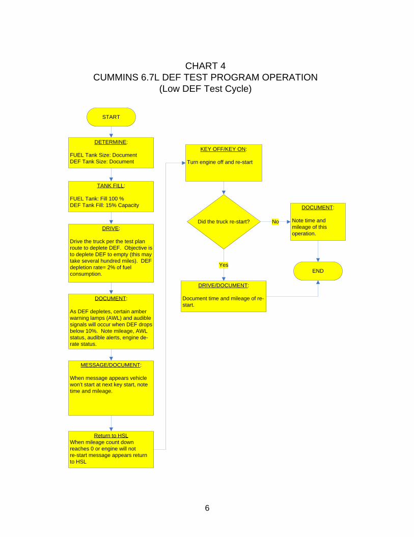
6
CHART 4CUMMINS 6.7L DEF TEST PROGRAM OPERATION
(Low DEF Test Cycle)
DETERMINE:
FUEL Tank Size: DocumentDEF Tank Size: Document
START
TANK FILL:
FUEL Tank: Fill 100 %DEF Tank Fill: 15% Capacity
DRIVE:
Drive the truck per the test plan route to deplete DEF. Objective is to deplete DEF to empty (this may take several hundred miles). DEF depletion rate= 2% of fuel consumption.
DOCUMENT:
As DEF depletes, certain amber warning lamps (AWL) and audible signals will occur when DEF drops below 10%. Note mileage, AWL status, audible alerts, engine de-rate status.
Did the truck re-start?
DRIVE/DOCUMENT:
Document time and mileage of re-start.
YesEND
DOCUMENT:
Note time and mileage of this operation.
No
MESSAGE/DOCUMENT:
When message appears vehicle won’t start at next key start, note time and mileage.
Return to HSLWhen mileage count down reaches 0 or engine will not re-start message appears return to HSL
KEY OFF/KEY ON:
Turn engine off and re-start

7
MESSAGE/DOCUMENT:
Record time and mileage when message appears stating that requires dealer repairs (250 mile warning)
CHART 5CUMMINS 6.7L DEF TEST PROGRAM OPERATION
(DEF Dilution Test Cycle)
DETERMINE:
FUEL Tank Size: DocumentDEF Tank Size: Document
START
TANK FILL:
FUEL Tank: Fill 100 %DEF Tank Fill: Verify DEF is at 0% fill; Fill DEF tank with Water to 100% Capacity (DO NOT ADD DEF)
DRIVE:
Start vehicle and drive the truck per the test plan route. Record time and mileage for vehicle to illuminate AWLs.
DOCUMENT:
Note all MIL’s, warning lamps, and other inducements. Note time and mileage on provided chart
DOCUMENT:
Note all MIL’s, warning lamps, and other inducements. Note time and mileage on provided chart
Did the truck re-start?
DRIVE:
Document time and mileage of attempted re-start.
END
DOCUMENT:
Note all MIL’s, warning lamps, and other inducements. Note time and mileage on provided chart
Yes
No
DRIVE:
Start vehicle and drive the truck per the test plan route. Record time and mileage for vehicle to enter 500 mile to no-start countdown
Return to HSLReturn to HSL when counter
reaches 0 miles. Do Not Key Off until the vehicle is returned to
HSL.

8
CHART 6CUMMINS 6.7L DEF TEST PROGRAM OPERATION
(DEF Tamper Test Cycle)
MESSAGE/DOCUMENT:
Record time and mileage when message appears stating that requires dealer repairs (250 mile warning)
DETERMINE:
FUEL Tank Size: DocumentDEF Tank Size: Document
START
TANK FILL:
FUEL Tank: Fill 100 %DEF Tank Fill: Verify DEF is at 0% fill; Fill DEF tank to 100% capacity with DEF; Maintenance: disconnect DEF Doser Valve
DRIVE:
Start vehicle and drive the truck per the test plan route. Record time and mileage for vehicle to illuminate AWLs.
DOCUMENT:
Note all MIL’s, warning lamps, and other inducements. Note time and mileage on provided chart
DOCUMENT:
Note all MIL’s, warning lamps, and other inducements. Note time and mileage on provided chart
Did the truck re-start?
DRIVE:
Document time and mileage of attempted re-start.
END
DOCUMENT:
Note all MIL’s, warning lamps, and other inducements. Note time and mileage on provided chart
Yes
No
DRIVE:
Start vehicle and drive the truck per the test plan route. Record time and mileage for vehicle to enter 500 mile to no-start countdown
Return to HSLReturn to HSL when counter
reaches 0 miles. Do Not Key Off until the vehicle is returned to
HSL.
9
Enclosure 3
Test Routes
Map 1 & Map 2

10
Map 1, El Monte to Baker
Summary: 166.9 miles (2 hours, 22 minutes)
Time Mile Instruction For Toward 9:00 AM
0.0 Depart 9528 Telstar Ave, El Monte, CA 91731 on Telstar Ave (East)
0.4 mi
9:00 AM 0.4 Turn RIGHT (East) onto Flair Dr 0.2 mi 9:01 AM 0.6 Take Ramp (RIGHT) onto I-10 [San
Bernardino Fwy] 29.8 mi I-10
9:26 AM 30.4 Take Ramp (RIGHT) onto I-15 [Ontario Fwy] 14.1 mi I-15 / Barstow / Las Vegas 9:38 AM 44.5 At exit 123, take Ramp (LEFT) onto I-15
[Barstow Fwy] 121.2 mi
I-15 / Barstow
11:20 AM
165.7 Turn RIGHT onto Ramp 0.2 mi CA-127 / Kelbaker Rd / Death Valley
11:21 AM
166.0 Turn LEFT (North-West) onto SR-127 [Kelbaker Rd]
0.9 mi
11:22 AM
166.9 Arrive Baker

11
Map 2, Baker to El Monte
Summary: 168.3 miles (2 hours, 24 minutes)
Time Mile Instruction For Toward 9:00 AM
0.0 Depart Baker on SR-127 (South) 0.7 mi
9:01 AM 0.7 Take Ramp (RIGHT) onto I-15 120.8 mi
I-15
10:43 AM
121.4 Take Ramp (RIGHT) onto I-15 [Ontario Fwy] 14.3 mi I-15 / Los Angeles / San Diego
10:55 AM
135.8 Take Ramp (RIGHT) onto I-10 [San Bernardino Fwy]
31.3 mi I-10 / Los Angeles
11:21 AM
167.0 At exit 26B, turn RIGHT onto Ramp 0.1 mi CA-19 / Rosemead Blvd
11:21 AM
167.2 Keep STRAIGHT to stay on Ramp 0.1 mi CA-19 N / Rosemead Blvd / Pasadena
11:22 AM
167.3 Keep LEFT to stay on Ramp 32 yds Rosemead Blvd
11:22 AM
167.3 Bear LEFT (West) onto Glendon Way 43 yds
11:22 AM
167.3 Turn LEFT (South) onto SR-19 [Rosemead Blvd]
0.5 mi
11:22 AM
167.8 Turn LEFT (North-East) onto Telstar Ave 0.5 mi
11:24 AM
168.3 Arrive 9528 Telstar Ave, El Monte, CA 91731

12
Enclosure 4 Vehicle Test Cycle Operation Form
Project #: __________________ Date: ______________ Vehicle #: ________ Chart # ________
Driver: ___________________ Observer: __________________ Vehicle License #: ______________
Fuel Tank Capacity: _______ gal DEF Tank Capacity: ________ gal Test Cycle: _______________
Date Time Odometer
DEF Tank Type Fluid
Added
Amt Fluid
Added
DEF Gauge Level
Diesel Fuel
Added
Diesel Gauge Level
Engine Performance.
Note any changes of
power de-rate
Engine Start
Engine Stop
Vehicle Speed
How Many AWLs
Red Light Indicator Comments

Appendix D – Test Plan 1Q1102

Matthew Rodriquez Secretary for
Environmental Protection
The energy challenge facing California is real. Every Californian needs to take immediate action to reduce energy consumption. For a list of simple ways you can reduce demand and cut your energy costs, see our website: http://www.arb.ca.gov.
California Environmental Protection Agency
Printed on Recycled Paper
Air Resources Board Mary D. Nichols, Chairman
9480 Telstar Avenue, Suite 4 El Monte, California 91731 • www.arb.ca.gov
Edmund G. Brown Jr.
Governor
TO: Annette Hebert, Chief Mobile Source Operations Division THROUGH: Thong Sten Vehicle Data Services Section FROM: John M. Urkov, Chief In-Use Vehicle Programs Branch DATE: December 5, 2011 SUBJECT: EVALUATION OF ON-ROAD HEAVY-DUTY DIESEL NOx CONTROL
STRATEGIES ON IN-USE 2011 MODEL YEAR DIESEL ENGINES (Revision - 3)
The In-Use Compliance Section (IUCS) will conduct an evaluation of on-road heavy-duty diesel (HDD) oxides of nitrogen (NOx) control strategies on in-use 2011 model year (MY) diesel engines. Staff will compare baseline emissions over prescribed driving routes when the NOx control strategies are functioning under proper operating circumstances to various tampered condition operation, along with the effectiveness of any driver inducements that are deployed. The two NOx control strategies that will be evaluated under this test plan are Exhaust Gas Recirculation (EGR), an in-cylinder control strategy, and Selective Catalytic Reduction (SCR), an after-treatment control strategy. SCR-equipped engines require the driver to periodically replenish the SCR system with Diesel Exhaust Fluid (DEF) to achieve NOx control. In order to discourage drivers from tampering with their SCR systems through either not refilling with DEF, using water or other inappropriate solution in place of DEF, or otherwise tampering with SCR system hardware, driver inducements in the form of visual and/or audible warnings and power de-rates usually precede final immobilization of the vehicle. EGR-equipped engine NOx control is achieved by recirculating a portion of the engine’s exhaust back into the engine’s air intake system. In the case of EGR equipped engines, drivers may desire to achieve more power by turning off or otherwise tampering with the EGR system. In addition, ARB has approved the use of auxiliary emission control devices (AECD), allowing under particular circumstances for EGR to be turned off accompanied by engine power de-rates to discourage the driver from continuing to operate under the undesirable circumstances.

2.
The IUCS staff will procure three heavy-duty vehicles each with a 2011 model year heavy-duty diesel engine (two SCR-equipped and one EGR-equipped). As each procured test vehicle is delivered to ARB’s Haagen-Smit Laboratory, the IUCS staff will first operate the accepted test vehicle over the project test route to establish NOx baseline emission levels utilizing a Portable Emissions Measurement System (PEMS) device. After baseline testing is completed for the SCR-equipped test vehicles, IUCS staff will examine the vehicle owner’s manuals, and if necessary consult with confidential business information submitted under the certification process, to determine the expected inducement strategies for each vehicle in this evaluation. Typically, these include a sequence of visual and/or audible warnings on the instrument panel (e.g. warning lights, chimes, and/or text message displays) indicating that DEF supply is low or a problem exists with the SCR system. As additional mileage is accumulated without remedying the problem or refilling the DEF supply, further driver inducements should occur, such as power de-rates or limited vehicle speed. Ultimately, if the problem is not corrected a severe inducement or final immobilization in the form of a no-start condition, or 5 mile per hour (mph) maximum speed limit, or idle-only operation should be triggered once the vehicle reaches a safe harbor (e.g. when refueling the vehicle, turning off the vehicle or idling the vehicle for an extended period of time). IUCS staff will observe and document the various driver warnings and inducements triggered by the SCR system while operating the vehicle under the conditions of depleted DEF, poor DEF quality, and a tampered SCR system. In addition, staff will continuously measure NOx emissions for each of these test cycles as the vehicle is being operated over the project test route. In regards to the EGR-equipped test vehicle, with the baseline test cycle established, IUCS staff will create a tampered condition of the EGR system and observe and document all (if any) driver warnings and vehicle performance issues caused by this tampering event. Staff may also attempt to trigger an AECD condition and evaluate the effectiveness of any driver inducements triggered. Staff will continuously measure NOx emissions under this test cycle as the vehicle is being operated over the project test route. This project is expected to commence as soon vehicle procurement has been established, and will be completed in approximately twelve weeks. Attachment

Test Plan
EVALUATION OF ON-ROAD HEAVY-DUTY DIESEL NOx CONTROL STRATEGIES ON IN-USE 2011 MODEL YEAR DIESEL ENGINES
Project Number: 1Q1102
July 22, 2011
Revised
July 25, 2011
August 11, 2011 December 5, 2011
Project Engineers: John O’Cain Bob Torres
In-Use Compliance Section In-Use Vehicle Programs Branch
Mobile Source Operations Division Air Resources Board
Haagen-Smit Laboratory 9528 Telstar Avenue El Monte, CA 9l73l

TEST PLAN EVALUATION OF ON-ROAD HEAVY-DUTY DIESEL NOx CONTROL
STRATEGIES ON IN-USE 2011 MODEL YEAR DIESEL ENGINES
I. SCOPE
The In-Use Compliance Section (IUCS) will conduct an evaluation of on-road heavy-
duty diesel (HDD) oxides of nitrogen (NOx) control strategies on in-use 2011 model
year (MY) diesel engines. Staff will compare baseline emissions over prescribed driving
routes when the NOx control strategies are functioning under proper operating
circumstances to various tampered condition operation, along with the effectiveness of
any driver inducements that are deployed. The two NOx control strategies that will be
evaluated under this test plan are Exhaust Gas Recirculation (EGR), an in-cylinder
control strategy, and Selective Catalytic Reduction (SCR), an after-treatment control
strategy.
SCR-equipped engines require the driver to periodically replenish the SCR system with
Diesel Exhaust Fluid (DEF) to achieve NOx control. In order to discourage drivers from
tampering with their SCR systems through either not refilling with DEF, using water or
other inappropriate solution in place of DEF, or otherwise tampering with SCR system
hardware, driver inducements in the form of visual and/or audible warnings and power
de-rates usually precede final immobilization of the vehicle.
EGR-equipped engine NOx control is achieved by recirculating a portion of the engine’s
exhaust back into the engine’s air intake system. In the case of EGR equipped engines,
drivers may desire to achieve more power by turning off or otherwise tampering with the
EGR system. In addition, ARB has approved the use of auxiliary emission control
devices (AECD), allowing under particular circumstances for EGR to be turned off

2
accompanied by engine power de-rates to discourage the driver from continuing to
operate under the undesirable circumstances.
The IUCS staff will procure three heavy-duty vehicles each with a 2011 model year
heavy-duty diesel engine (two SCR-equipped and one EGR-equipped). As each
procured test vehicle is delivered to ARB’s Haagen-Smit Laboratory, the IUCS staff will
first operate the accepted test vehicle over the project test route to establish NOx
baseline emission levels utilizing a Portable Emissions Measurement System (PEMS)
device.
After baseline testing is completed for the SCR-equipped test vehicles, IUCS staff will
examine the vehicle owner’s manuals, and if necessary consult with confidential
business information submitted under the certification process, to determine the
expected inducement strategies for each vehicle in this evaluation. Typically, these
include a sequence of visual and/or audible warnings on the instrument panel (e.g.
warning lights, chimes, and/or text message displays) indicating that DEF supply is low
or a problem exists with the SCR system. As additional mileage is accumulated without
remedying the problem or refilling the DEF supply, further driver inducements should
occur, such as power de-rates or limited vehicle speed. Ultimately, if the problem is not
corrected a severe inducement or final immobilization in the form of a no-start condition,
or 5 mile per hour (mph) maximum speed limit, or idle-only operation should be
triggered once the vehicle reaches a safe harbor (e.g. when refueling the vehicle,
turning off the vehicle or idling the vehicle for an extended period of time). IUCS staff
will observe and document the various driver warnings and inducements triggered by
the SCR system while operating the vehicle under the conditions of depleted DEF, poor
DEF quality, and a tampered SCR system. In addition, staff will continuously measure
NOx emissions for each of these test cycles as the vehicle is being operated over the
project test route.

3
In regards to the EGR-equipped test vehicle, with the baseline test cycle established,
IUCS staff will create a tampered condition of the EGR system and observe and
document all (if any) driver warnings and vehicle performance issues caused by this
tampering event. Staff may also attempt to trigger an AECD condition and evaluate the
effectiveness of any driver inducements triggered. Staff will continuously measure NOx
emissions under this test cycle as the vehicle is being operated over the project test
route.
NOTE: Only one vehicle will be evaluated at a time during this project.
II. PROGRAM MANAGEMENT
The IUCS staff will administer this test program with the assistance of the Mobile
Source Control Division’s (MSCD) In-Use Retrofit Section who will outfit the vehicle with
a PEMS unit to monitor/measure the exhaust emissions as the vehicle is driven through
the designated test route. In addition, the IUCS staff may utilize the Heavy Duty Diesel
I/M Development Section to conduct PEMS testing for this project. The IUCS will
provide a project engineer for each individual vehicle: the project engineer will be the
contact for all issues related to the completion of this program.
III. VEHICLE PROCUREMENT
California Environmental Engineering (CEE), ARB’s current procurement contractor, will
deliver the test vehicles for this program based on the specifications provided to the
Laboratory Logistics and Test Support (LLTS) Section by the project engineers. Each
test vehicle will be operated out of the ARB’s HSL by an ARB driver possessing a valid
California Class A driver’s license.
IUCS staff has already rented K-Rail and a trailer that will be towed behind each of the
test vehicles. This trailer will allow a test vehicle’s engine load to vary from nearly full
power conditions, when traveling uphill, to a near zero engine load when traveling
downhill.

4
The IUCS staff will also secure an experimental operating permit from the Aftermarket
Parts Section for each test vehicle. This permit is necessary when operating a vehicle
outside of its certified condition on California roadways.
IV. VEHICLE DELIVERY AND CHECK-IN
Vehicles will be checked-in and all pre-existing damage will be documented and
photographed upon check-in.
V. TEST FUEL REQUIREMENTS
Commercially available low sulfur diesel fuel will be used for this program. Diesel fuel
and DEF will be purchased at any local supplier that accepts the California Voyager
Card.
VI. VEHICLE MAINTENANCE
Any necessary maintenance of the test vehicle will be performed by the LLTS staff;
maintenance that cannot be done using LLTS staff will be performed by a local
maintenance vendor. Any required maintenance must be authorized by the project
engineer prior to the work being performed.
VII. TESTING
The test vehicle will be evaluated while driving over the project test route (see Project
Test Route and Lean Cruise Test Route) following the testing patterns as prescribed in
the enclosed test cycle charts (see Charts 1-8). Each vehicle will be outfitted with a
PEMS unit so that on-road emissions can be continuously monitored measured
throughout each test cycle by MSCD’s In-Use Retrofit Section (testing may also be
conducted by the Heavy Duty Diesel I/M Development Section). Each test vehicle will
have two staff on-board while operating the vehicle during its test cycles (i.e., one driver
and one staff to operate the PEMS unit). The test vehicles will be operated for as many
miles as possible during a normal work shift. Because each test vehicle will be loaded
to near full load capacity, all safety precautions must be taken when operating these
vehicles. Staff will adhere to all State and federal traffic laws. In the case of an

5
accident, the California Highway Patrol or local police authority and the project engineer
must be notified immediately.
- SCR-Equipped Truck Evaluation
A baseline evaluation will be performed on the SCR-equipped vehicle (see Chart 1) to
establish normal vehicle operation parameters and emission values. Once the baseline
evaluation is completed, the vehicles will be driven and evaluated as per the established
test patterns shown in Charts 2-5. Under each test cycle staff will observe and
document on the Vehicle Test Cycle Operation Form (enclosed) any visual warnings,
audible alerts and vehicle performance problems propagated by the prescribed SCR
test cycles. On-road emissions will be continuously measured throughout each test
cycle with the on-board PEMS unit.
- EGR-Equipped Truck Evaluation
A baseline evaluation will be performed on the EGR-equipped vehicle (see Chart 6) to
establish normal vehicle operation parameters and emission values. Once the baseline
evaluation is completed, the vehicle will be driven and evaluated as per the established
test patterns shown in Chart 7. Under this test cycle staff will observe and document on
the Vehicle Test Cycle Operation Form (enclosed) any visual warnings, audible alerts
and vehicle performance problems promulgated by the tampered EGR system. On-
road emissions will be continuously measured throughout each test cycle with the on-
board PEMS unit. The EGR equipped truck will undergo additional testing utilizing a
test route where the truck can maintain a constant speed of 55 mph (see Lean Cruise
Test Route - attached). The lean cruise test cycle (see Chart 8) is being utilized to
determine if any lean cruise calibrations exist that may have an impact on NOx
emissions.
VIII. DATA HANDLING AND PROCESSING
All data will be reviewed by the project engineers for completeness and accuracy. The
In-Use Retrofit Section will review, quality audit and forward the PEMS emissions data

6
to the applicable project engineer upon its acceptance. All emission data sampled
during this project will be analyzed using a PEMS unit; the data generated will not be
entered into the VEDS database, also this project does not require a test engineer.
IX. DOCUMENTATION
It is of the utmost importance that all forms, documents, test data sheets, etc., are
accurate and complete.
X. LABORATORY VISITORS
The project engineers must be notified if a non-ARB staff member is to be involved in
the project. Persons other than ARB staff members may not occupy the vehicles while
they are operated on the roadways, unless advance approval is granted by the project
engineer.
XI. VEHICLE RELEASE
A test vehicle will be released from the program when the project engineer releases the
test vehicle to the procurement contract manager.
Enclosures

7

8

9

10

11

12

13

14

15
PROJECT TEST ROUTE
ARB [9528 Telstar Ave, El Monte, CA 91731] I-10 east CA-605 north CA-210 east I-15 north US-395 north Joshua St, Hesperia, CA 92344 I-15 south CA-210 west North Campus Ave, Upland, CA 91784 CA-210 east
I-15 north US-395 north
Joshua St, Hesperia, CA 92344 I-15 south CA-210 west
I-15 south CA-210 west CA-605 south
I-10 west ARB [9528 Telstar Ave, El Monte, CA 91731]
SUMMARY - Approximated driving distance: 197 miles

16
LEAN CRUISE TEST ROUTE
Start 4 Street on ramp into I-15 south
Exit I-15 to Limonite
Limonite on-ramp to I-15 North
Exit I-15 to 4th street
Summary: Approximated driving distance 14.8 miles

17
Vehicle Test Cycle Operation Form
Project #: __________________ Date: ______________ Vehicle #: ________ Chart # ________
Driver: ___________________ Observer: __________________ Vehicle License #: ______________
Fuel Tank Capacity: _______ gal DEF Tank Capacity: ________ gal Test Cycle: _______________
Date Time Odometer
DEF Tank Type Fluid
Added
Amount Fluid
Added
DEF Gauge Level
Diesel Fuel
Added
Diesel Gauge Level
Engine Performance.
Note any changes of
power de-rate Engine Start
Road Grade
(Uphill/Flat/Downhill)
Vehicle Speed
How Many AWLs
Red Light Indicator Comments
AWL – Amber Warning Light