Air Plasma Cutter - media.bluestonepim.com€¦ · 6 User instruction manual 7 Replacement filter...
44
Revision date: 16-07-08 Page 1 of 44 Instruction manual UPC 1041 TP Air Plasma Cutter
Transcript of Air Plasma Cutter - media.bluestonepim.com€¦ · 6 User instruction manual 7 Replacement filter...

Revision date: 16-07-08 Page 1 of 44
Instruction manual
UPC 1041 TPAir Plasma Cutter
Revision date: 16-07-08 Page 2 of 44
CONTENTS
1. TECHNICAL DATA
2. INSTALLATION
3. OPERATING INSTRUCTIONS
4. TORCH PARTS
5. MAINTENANCE
6. TROUBLE SHOOTING
7. SAFETY INSTRUCTIONS
8. SERVICE SECTION
UPC-1041 TP Air Plasma Cutter 404121 delivery consist of:
1 Machine supply complete with 6m primary cable 3+G 4mm2 Torch with 6m cable package3 Return clamp with 4m cable and Dix cable connector4 Accessories kit with initial supply of torch spares and consumables5 Air regulator with filter and water separator on the machine6 User instruction manual7 Replacement filter
Remarks: Plug for primary cable and air hose is not supplied as this will depend on the connectionsavailable onboard.
Revision date: 16-07-08 Page 3 of 44
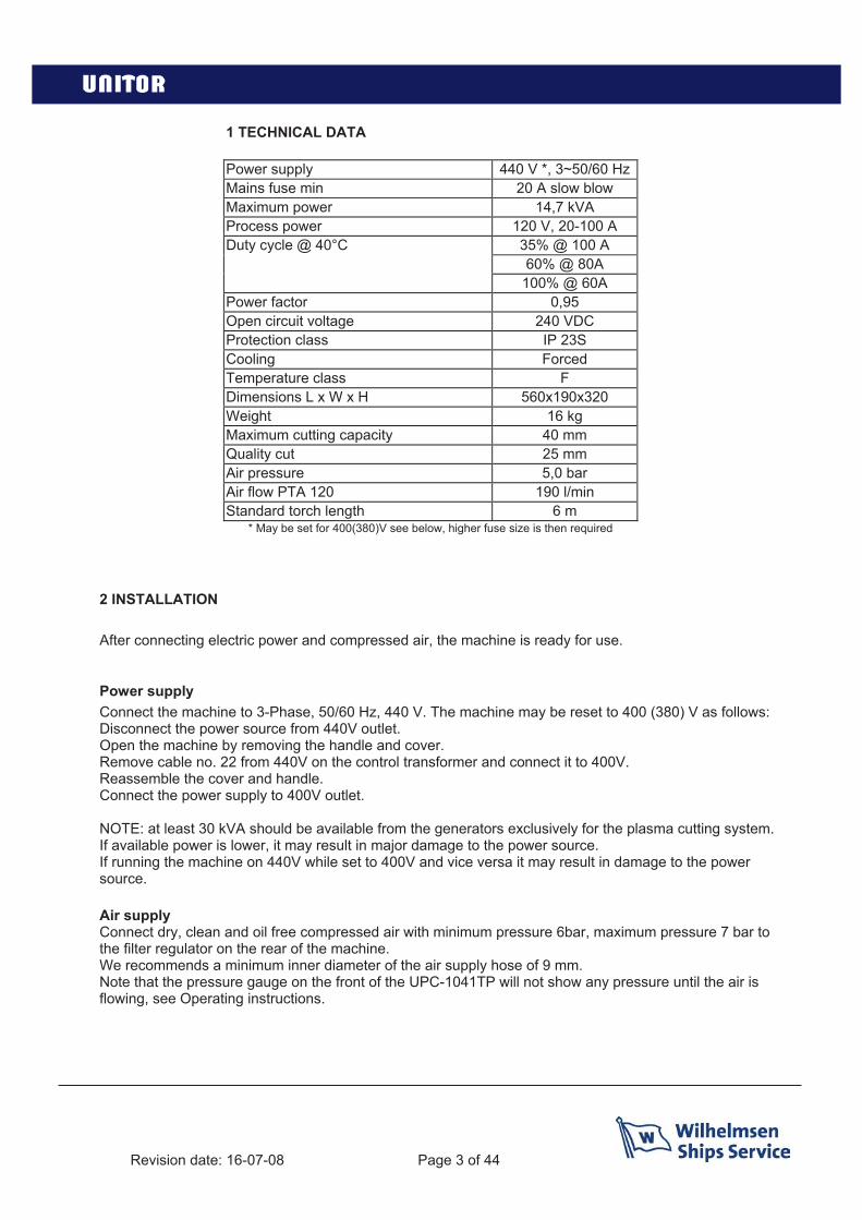
1 TECHNICAL DATA
Power supply 440 V *, 3~50/60 HzMains fuse min 20 A slow blowMaximum power 14,7 kVAProcess power 120 V, 20-100 ADuty cycle @ 40°C 35% @ 100 A
60% @ 80A100% @ 60A
Power factor 0,95Open circuit voltage 240 VDCProtection class IP 23SCooling ForcedTemperature class FDimensions L x W x H 560x190x320Weight 16 kgMaximum cutting capacity 40 mmQuality cut 25 mmAir pressure 5,0 barAir flow PTA 120 190 l/minStandard torch length 6 m
* May be set for 400(380)V see below, higher fuse size is then required
2 INSTALLATION
After connecting electric power and compressed air, the machine is ready for use.
Power supplyConnect the machine to 3-Phase, 50/60 Hz, 440 V. The machine may be reset to 400 (380) V as follows: Disconnect the power source from 440V outlet.Open the machine by removing the handle and cover.Remove cable no. 22 from 440V on the control transformer and connect it to 400V.Reassemble the cover and handle.Connect the power supply to 400V outlet.
NOTE: at least 30 kVA should be available from the generators exclusively for the plasma cutting system. If available power is lower, it may result in major damage to the power source.If running the machine on 440V while set to 400V and vice versa it may result in damage to the power source.
Air supplyConnect dry, clean and oil free compressed air with minimum pressure 6bar, maximum pressure 7 bar to the filter regulator on the rear of the machine.We recommends a minimum inner diameter of the air supply hose of 9 mm.Note that the pressure gauge on the front of the UPC-1041TP will not show any pressure until the air is flowing, see Operating instructions.
Revision date: 16-07-08 Page 4 of 44
3 OPERATING INSTRUCTIONS
Check that the machine has been properly connected to power supply and compressed air according to chapter 2, INSTALLATION.
Check that the torch is fitted with appropriate consumables for the job at hand.
Connect the return clamp directly onto the work piece, ensuring that a good contact is obtained. If necessary, clean the surface from paint, rust, dirt, etc.
Switch the machine’s main power switch on. The READY lamp will light and the fan will start working.
Choose process power, 20-100 Ampere.
Press trigger shortly to start air pre-flow and check air pressure: 4.5 – 5.0 bar. When cutting at lower amperage than 70 A it may be necessary to lower the air pressure to 4.5 bar in order to get the best cutting capability. Do not forget to raise the pressure again to 5 bar if returning to amperage above 70 A.
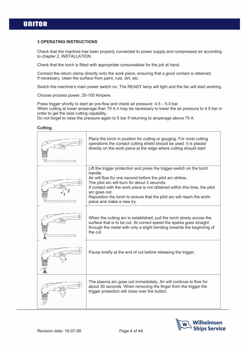
Cutting
Place the torch in position for cutting or gouging. For most cutting operations the contact cutting shield should be used. It is placed directly on the work piece at the edge where cutting should start
Lift the trigger protection and press the trigger-switch on the torch handle.Air will flow for one second before the pilot arc strikes. The pilot arc will burn for about 3 seconds. If contact with the work piece is not obtained within this time, the pilot arc goes out. Reposition the torch to ensure that the pilot arc will reach the work-piece and make a new try.
When the cutting arc is established, pull the torch slowly across thesurface that is to be cut. At correct speed the sparks goes straight through the metal with only a slight bending towards the beginning of the cut
Pause briefly at the end of cut before releasing the trigger.
The plasma arc goes out immediately. Air will continue to flow for about 30 seconds. When removing the finger from the trigger the trigger protection will close over the button.
Revision date: 16-07-08 Page 5 of 44
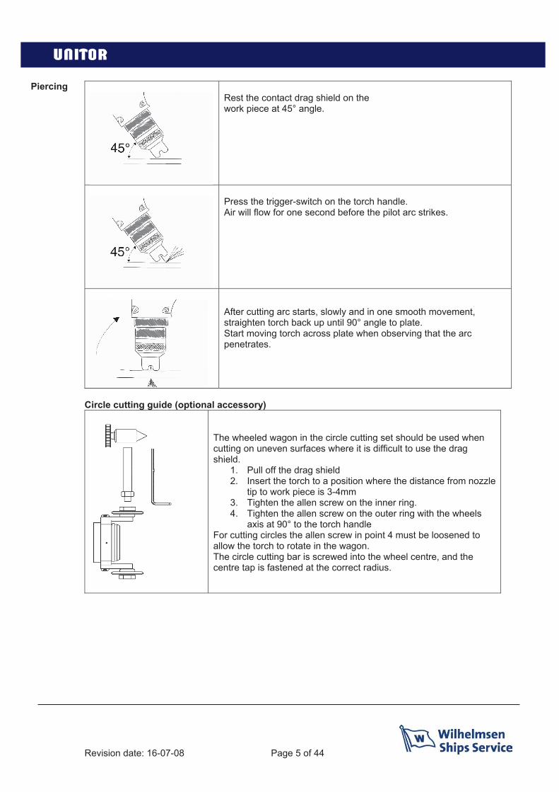
PiercingRest the contact drag shield on the work piece at 45° angle.
Press the trigger-switch on the torch handle.Air will flow for one second before the pilot arc strikes.
After cutting arc starts, slowly and in one smooth movement, straighten torch back up until 90° angle to plate. Start moving torch across plate when observing that the arc penetrates.
Circle cutting guide (optional accessory)
The wheeled wagon in the circle cutting set should be used when cutting on uneven surfaces where it is difficult to use the drag shield.
1. Pull off the drag shield2. Insert the torch to a position where the distance from nozzle
tip to work piece is 3-4mm3. Tighten the allen screw on the inner ring.4. Tighten the allen screw on the outer ring with the wheels
axis at 90° to the torch handleFor cutting circles the allen screw in point 4 must be loosened to allow the torch to rotate in the wagon.The circle cutting bar is screwed into the wheel centre, and the centre tap is fastened at the correct radius.

Revision date: 16-07-08 Page 6 of 44
Gouging 1 Pull off the drag shield and shield cup2 Mount the gouging nozzle and replace the shield cup3 Contact gouging cannot be done. Start the arc with the nozzle at 45° angle, slightly off the work
piece.4 When gouging arc is established, move the torch forward, blowing the molten metal out of the
groove.5 Groove depth and width is adjusted by weaving and torch angle.
NOTE! When the machine is not in use or is only working at long intervals, switch off the machine. It contains mechanical components that should not be exposed to unnecessary wear. It also protects against accidental firing the pilot arc.

Revision date: 16-07-08 Page 7 of 44
4 TORCH PARTS

Revision date: 16-07-08 Page 8 of 44
Pos.no Description Product no- UPC-1041TP Plasma cutter complete with 6m cable 404121- Torch PTA 121 with 6m cable and drag shield for UPC-
1041 (incl. w. machine)404114
- Torch PTA 121 with 15 m cable and drag shield for UPC-1041 (optional)
404115
1 (not shown)
Hose assembly for PTA 121 torch 6m, excl. torch head and handle.
On request
1 (not shown)
Hose assembly for PTA 121 torch 15m, excl. torch head and handle
On request
2 Trigger button for UPC-1041 w. PTA 121 On request3 Handle for UPC-1041 w. PTA 121 On request4 Torch head for UPC-1041 w. PTA 121 On request5 Electrode for UPC-1041 w. PTA 121 5 pcs 4040056 Tool for electrode change -7 Swirl ring for UPC-1041 w. PTA 121 2 pcs 4040068 Nozzle 1,0mm 20-50 Amps for UPC-1041 w. PTA 121
5 pcs404007
8 Nozzle 1,2mm 50-100 Amps for UPC-1041 w. PTA 1215 pcs
404008
8 Nozzle gouging 2,5mm for UPC-1041 w. PTA 121 5pcs
404009
9 Shield cup for UPC-1041 w. PTA 121 2 pcs 40401010 Spatter shield for UPC-1041 w. PTA 121 2 pcs 40411111 Drag shield for UPC-1041 w. PTA 121 2 pcs 404112- Consumables kit complete (included with machine)
The kit includes 3 electrodes ( pos 5) 1 tool for electrodes ( pos 6) 3 nozzles 1,2 ( pos 8) 1 spatter shield ( pos 11) 1 drag shield ( pos 12)1 gouging nozzle 2,5 ( pos 9)
404013
12 Wheeled cutting guide with circle cutting attachment(Optional accessory)
404016
13 Filter kit UPC-1041TP On request
Revision date: 16-07-08 Page 9 of 44
5. MAINTENANCE
DAILYInspect and, if necessary, change the torch consumable parts.
Note:Electrode and nozzle must be changed at regular intervals, as a general guideline after 2 hourscontinous use, or after 200 starts.Always replace the electrode if the centre has a pit more than 2 mm (1/16” deep). Replace the nozzleif the opening is deformed or clearly oversized.Failure to replace worn nozzle or electrode in time will dramatically reduce the cutting capacity andeventually ruin the torch.
The moisture trap on the backside of the machine is self-relieving by pressure drop, this means thatevery time you start and stop a cutting cycle it will drain the moisture in the trap. If cleaning or manualemptying of the trap is necessary, completely unscrew the glass cup after disconnecting compressedair.
Carefully inspect the hose assembly and torch body with regard to any leak or damage.Never use a damaged torch.
EVERY THREE TO SIX MONTHSDisconnect the machine from compressed air and electricity.Remove the cover.Clean the machine with dry, clean and oil free compressed air. Inspect cable connections and gassystem.In especially dirty environments this procedure should be carried out more often.

Revision date: 16-07-08 Page 10 of 44
6. TROUBLE SHOOTING
TP- Total Protection
The UPC-1041TP is equipped with Total Protection – TP which monitors the input voltage and phasesand protects the machine when the voltage is outside the limits or one phase is missing in the mainssupply. If the TP LED is active when turning on the machine then check the input voltage and phases.
Thermal overload If the air pressure is correct but the green ready lamp is not lit the power source is overheated andneeds to cool down before it can be used again. Let the machine cool down while switched on until the ready lamp lights up.
Please note that the UPC-1041 TP plasma cutter is equipped with an active fan control which will run the fan until the machine is cooled down to a safe level.Here is a small description how it works:
The Active fan control will switch on the fan when the operator switches on the machine in order for the operator to hear that the machine starts up, if the operator doesn’t start a cutting cycle within 5min the machine will switch off the fan.
When the operator activates the torch the Active fan control will start the fan and keep it runningduring the whole cutting cycle and 5min after in order to cool the machine f the operator doesn’treactivate the torch during these 5min the fan switches off.
If the operator activates the torch within 5 min the Active fan control will reset the timing and when theoperator stops the cutting cycle the fan will again run for 5min.
As an added protection the Active fan control senses the temperature on the main transformer via a thermistor, if the transformer is still warm after the 5min time cycle the fan will keep running until the transformer has reached a preset temperature.
Torch malfunction If the pilot arc does not strike:
- Change nozzle, electrode and electrode insulator.- Check and if necessary, adjust inlet air pressure on the rear of the machine to 5 bar.- If possible, measure gas flow through the nozzle while the post flow function is active.
The flow should be approx. 20-28 l/min.
If the pilot arc is not stable:
- Too high gas flow. Adjust pressure to 5 bar.If possible measure the flow through the nozzle.
- The machine is working two-phase. Check mains fuses.
Inferior performance or cutting quality:
- Check consumables.- Inspect the torch body and hose assembly for damage.- Check the return clamp connection.

Revision date: 16-07-08 Page 11 of 44
7. SAFETY INSTRUCTIONS
All endangerments through plasma cutting are related with the process itself. Endangerments may occur due to:- High contact voltage- HV ignition- Electromagnetic interferences- Heat and light radiation- Gases, fumes and smoke- Noise- Hot metal and spatter- Handling of pressure cylindersThe Plasma Cutting Machine has been developed in conformity with following standards:• EN 60974-1 safety requirements for installations for arc welding and welding power sources• EN 60974-10 electromagnetic compatibility
Before starting the Plasma Cutting Machine carefully read this Instruction Manual. Only advised personnel are allowed to operate the plasma installation!
Endangerment due to high contact voltageWarning! Before opening the plasma cutting machine the input power has to be disconnected physically from the mains (unplug mains cable)! Only advised personnel are allowed to carry out any repairs to the machine.Attention! Connect the return lead clamp onto and earth the workplace before starting the machine!
Important precautionsConnect power source only to correctly earthed mains socket with proper connected protective earth conductor.Wear insulating protective clothing (safety shoes, leather apron, gloves), place torch on a surface insulated from machine earth during breaks,Keep cutting area and plasma machine components dry and clean and follow the maintenance recommendations strictly.
Working under elevated electrical endangerment This plasma cutting machine in conformity with valid standards (EN 60974-1) can be used for operation under elevated electrical endangerment. The design of the torch prevents electrical danger when the torch is disassembled. Therefore the power source is marked with the S-sign and operation under enhanced electrical endangerment is allowed. Attention! Always follow the local safety rules!
Endangerment through high voltage (HV) A HV-igniter starts the pilot arc. The HV-supply is cut-off automatically after pilot arc has struck. Attention! Never touch nozzle or nozzle cap when power source is switched ON! HV-ignition may establish electromagnetic fields and can influence heart pace-makers and electronic devices
Endangerment through electromagnetic interferences The plasma cutting unit is in conformity with the conditions of the EN 60974-10 “Electromagnetic compatibility”. This standard is valid for arc welding and related processes (plasma cutting) that come in use in commercial and private fields. Warning! Special precautions may be required if the plasma unit is used in private fields (for instance screened cables etc.) The user takes the full risk when installing and using the machine and must follow strictly these instructions. If electromagnetic interferences are noticed the user is to contact the producer to solve the problem.

Revision date: 16-07-08 Page 12 of 44
Recommendations to classify the environment (EN 60974): Before the installation takes place the user has to evaluate the environment for electromagnetic problems and to take into consideration: Other mains supplies, control cables, signal and telecommunication lines along, above, below or beside the installation. Broadcasting or television installations Computers or other controls Safety devices, protection circuits The health of people in the area (heart pace makers, hearing aids etc.) Devices for measuring and calibrating The noise immunity of equipment around the installation must be compatible with electromagnetic interferences. Special measures may be required.
Recommendations to minimize interferences: Apply filter for mains connection. Screening of mains cable of the plasma installation (safe contact between screen and housing required) Constant maintenanceAlways keep cover plates and doors of the plasma machines closedAvoid excessive length of cutting cablesArrange potential equalization between metallic parts around the installation (the operator has to be insulated from those parts)Proper return clamp connection onto the work pieceSelective screening of other cables and installations
Endangerment through heat and light radiationThe plasma arc produces intense ultraviolet and infrared radiation that can hurt the eyes and skin. Therefore the following precautions have to be arranged:Wearing of flame-retardant welding clothes (helmet, apron, gloves, safety shoes)Hand or head shield with protective glasses of medium shade for watching the cutting processPreparing the cutting area so that reflection and transmission of ultraviolet light is reduced if necessary use protective walls and screens
Endangerment through fumes and smokeDue to the plasma process itself hazardous substances may be produced. To avoid risks on health the following has to be done:Keep cutting place well ventilatedRemove fumes and smoke by exhaustion devicesRemove all chlorinated and other solvents from the cutting area. They could form phosgene gas when exposed to ultraviolet radiationWear a breathing mask when cutting galvanized materialsEnsure that toxic limits are not exceeded
Endangerment through noise Be aware that during plasma cutting a high noise level arises, and can reach levels above 100 decibel. Adequate ear protection must be used.
Endangerment through spatterDuring plasma cutting sparks, slag and hot metal are produced. The risk of burns and fire exists! To avoid these endangerments the following has to be advised:Remove all potential flammable materials from cutting area, at least in a 10 m distanceCool down freshly cut material before handlingMake fire extinguisher available in the cutting area
Revision date: 16-07-08 Page 13 of 44
8. SERVICE SECTION
Fault finding:
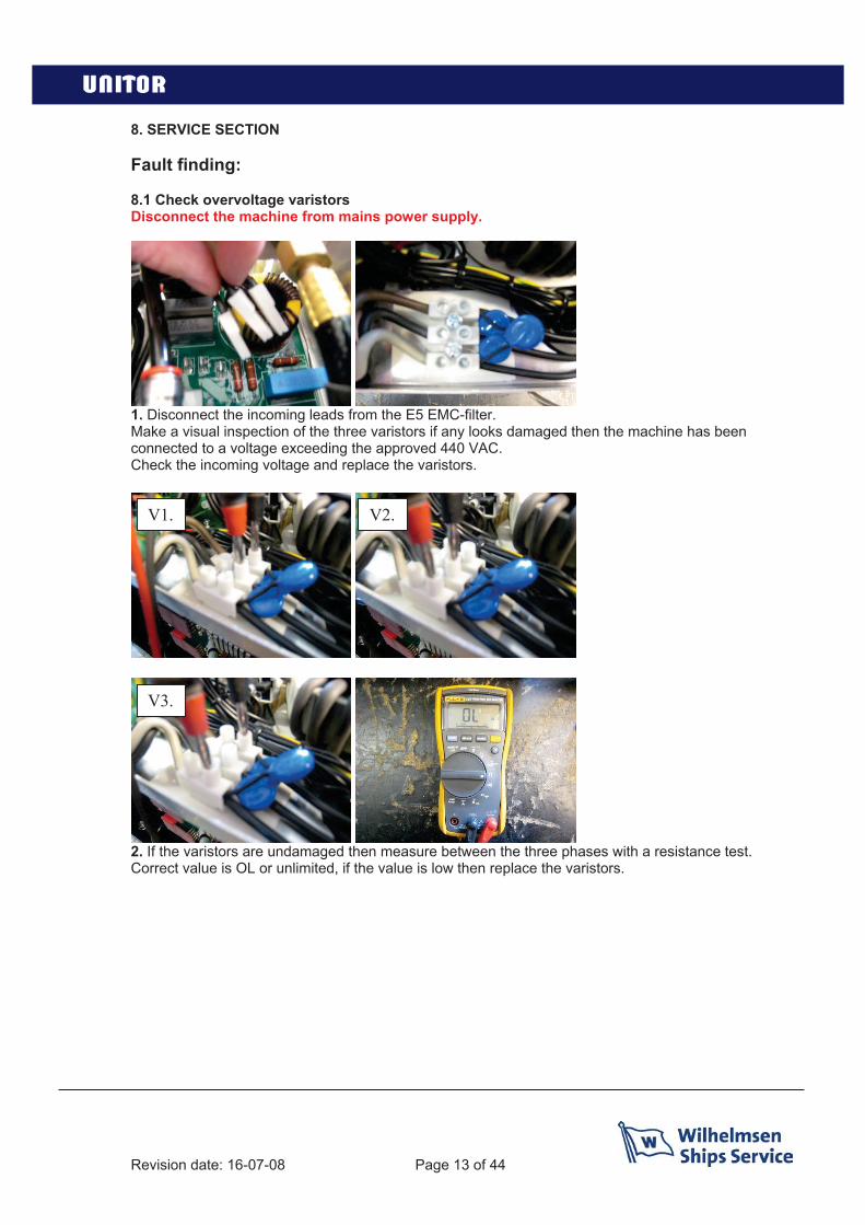
8.1 Check overvoltage varistorsDisconnect the machine from mains power supply.
1. Disconnect the incoming leads from the E5 EMC-filter.Make a visual inspection of the three varistors if any looks damaged then the machine has beenconnected to a voltage exceeding the approved 440 VAC.Check the incoming voltage and replace the varistors.
2. If the varistors are undamaged then measure between the three phases with a resistance test.Correct value is OL or unlimited, if the value is low then replace the varistors.
V1. V2.
V3.
Revision date: 16-07-08 Page 14 of 44
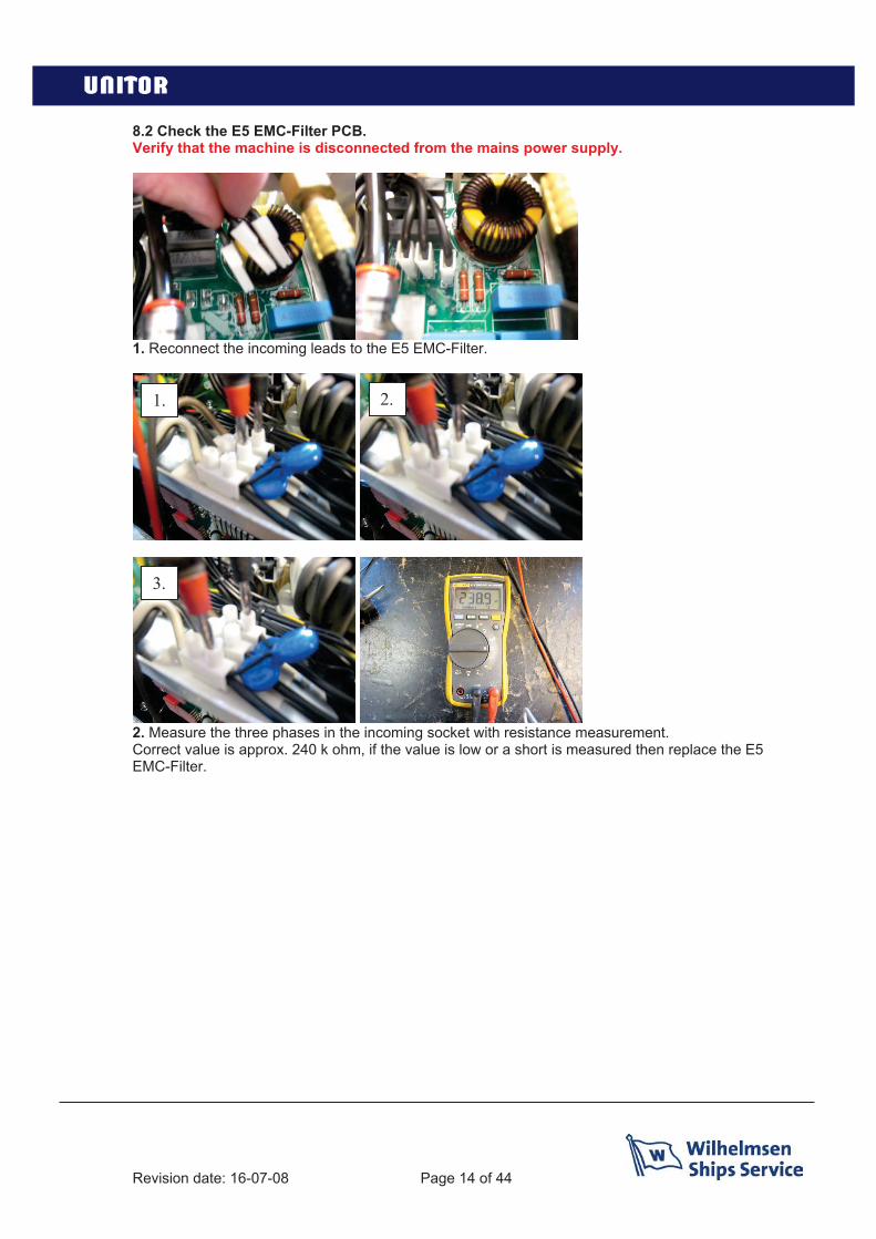
8.2 Check the E5 EMC-Filter PCB.Verify that the machine is disconnected from the mains power supply.
1. Reconnect the incoming leads to the E5 EMC-Filter.
2. Measure the three phases in the incoming socket with resistance measurement.Correct value is approx. 240 k ohm, if the value is low or a short is measured then replace the E5EMC-Filter.
1. 2.
3.
Revision date: 16-07-08 Page 15 of 44
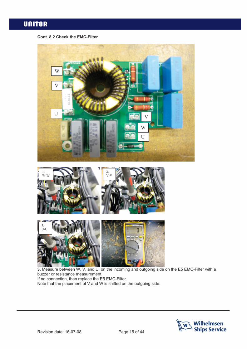
Cont. 8.2 Check the EMC-Filter
3. Measure between W, V, and U, on the incoming and outgoing side on the E5 EMC-Filter with a buzzer or resistance measurement.If no connection, then replace the E5 EMC-Filter.Note that the placement of V and W is shifted on the outgoing side.
W
V
V
W
U
U
1. W-W
2.V-V
3.U-U

Revision date: 16-07-08 Page 16 of 44
8.3 Check the B1 Main switch.Verify that the machine is disconnected from the mains supply.
1. Turn on B1 main switch. Remove the fuse from the T1 Control transformer.
2. Measure between the cables 11, 21 and 31 and the three phases on the incoming side on the mainswitch with a resistance or buzzer measurement.Correct value is 0 Ohm, if resistance is high then replace the B1 main switchReplace the fuse on the T1 control transformer and switch off B1 main switch.
1. 2.
3.
Revision date: 16-07-08 Page 17 of 44
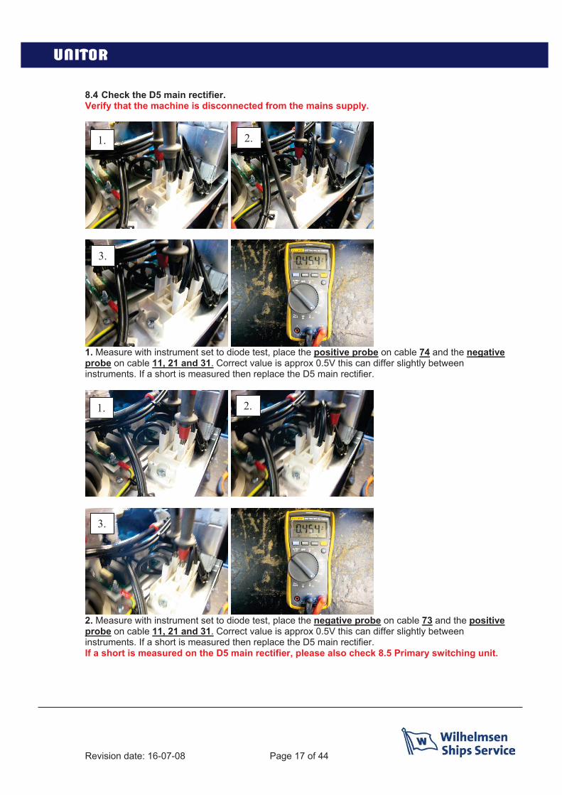
8.4 Check the D5 main rectifier.Verify that the machine is disconnected from the mains supply.
1. Measure with instrument set to diode test, place the positive probe on cable 74 and the negativeprobe on cable 11, 21 and 31. Correct value is approx 0.5V this can differ slightly betweeninstruments. If a short is measured then replace the D5 main rectifier.
2. Measure with instrument set to diode test, place the negative probe on cable 73 and the positiveprobe on cable 11, 21 and 31. Correct value is approx 0.5V this can differ slightly betweeninstruments. If a short is measured then replace the D5 main rectifier.If a short is measured on the D5 main rectifier, please also check 8.5 Primary switching unit.
1. 2.
3.
1. 2.
3.
Revision date: 16-07-08 Page 18 of 44
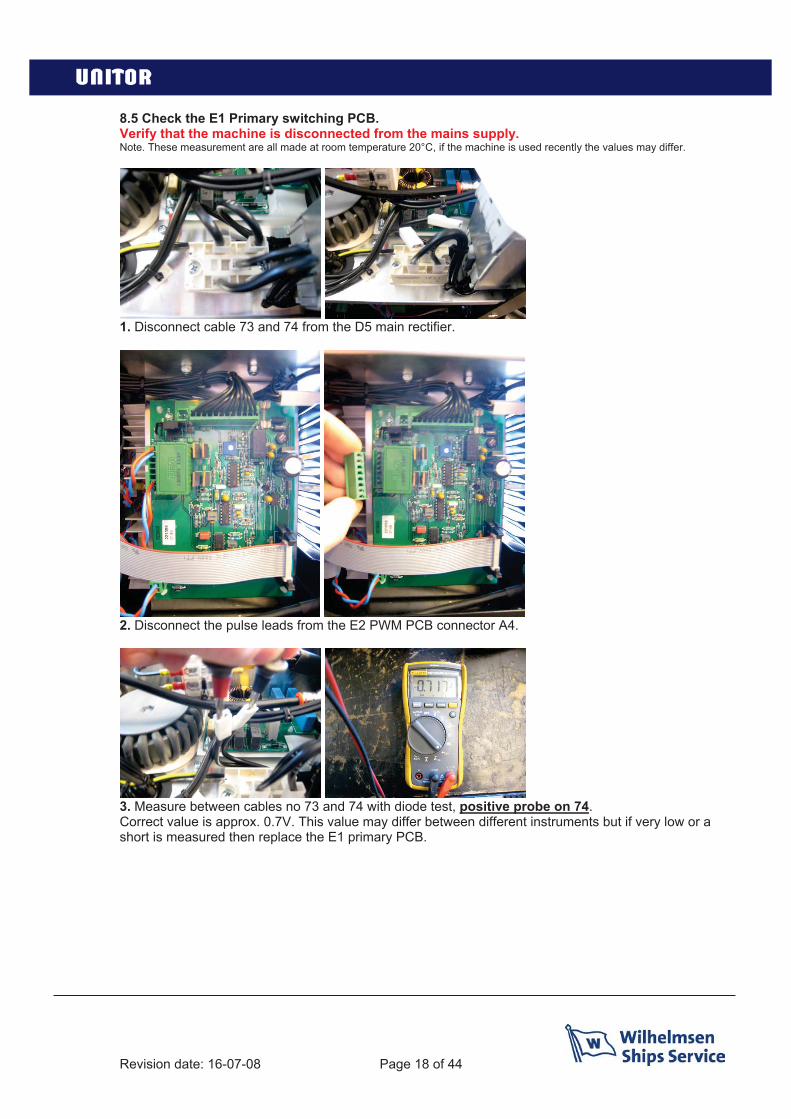
8.5 Check the E1 Primary switching PCB.Verify that the machine is disconnected from the mains supply.Note. These measurement are all made at room temperature 20°C, if the machine is used recently the values may differ.
1. Disconnect cable 73 and 74 from the D5 main rectifier.
2. Disconnect the pulse leads from the E2 PWM PCB connector A4.
3. Measure between cables no 73 and 74 with diode test, positive probe on 74.Correct value is approx. 0.7V. This value may differ between different instruments but if very low or a short is measured then replace the E1 primary PCB.
Revision date: 16-07-08 Page 19 of 44
Cont. 8.5 Check the E1 Primary switching PCB.
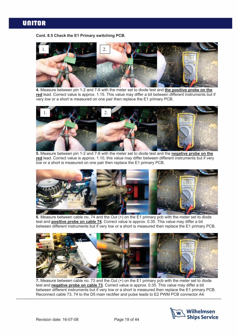
4. Measure between pin 1-2 and 7-8 with the meter set to diode test and the positive probe on the red lead. Correct value is approx. 1.15. This value may differ a bit between different instruments but if very low or a short is measured on one pair then replace the E1 primary PCB.
5. Measure between pin 1-2 and 7-8 with the meter set to diode test and the negative probe on the red lead. Correct value is approx. 1.10, this value may differ between different instruments but if very low or a short is measured on one pair then replace the E1 primary PCB.
6. Measure between cable no. 74 and the Out (+) on the E1 primary pcb with the meter set to diode test and positive probe on cable 74. Correct value is approx. 0.35. This value may differ a bit between different instruments but if very low or a short is measured then replace the E1 primary PCB.
7. Measure between cable no. 73 and the Out (+) on the E1 primary pcb with the meter set to diode test and negative probe on cable 73. Correct value is approx. 0.35. This value may differ a bit between different instruments but if very low or a short is measured then replace the E1 primary PCB.Reconnect cable 73, 74 to the D5 main rectifier and pulse leads to E2 PWM PCB connector A4.
1. 2.
1. 2.

Revision date: 16-07-08 Page 20 of 44
8.6 Check the E4 Secondary PCB.Note. These measurement are all made at room temperature 20°C, if the machine is used recently the values may differ.
1. Disconnect one of the main transformer leads and one of the choke leads.
2. Measure between D3A and D3B with diode test and the red probe on D3B.Correct value is approx. 0.35. If a low value or a short is measured replace the diode module D3/D4.
3. Measure between D2D and D2C with diode test and the red probe on D2C.Correct value is approx. 0.35. If a low value or a short is measured replace the diode module D1/D2.
4. Measure between TS1_B and TS1_C, with diode test and the positive probe on TS1_B.Correct value is approx. 0.35. If a low value or a short is measured replace the transistor module TS1.
Revision date: 16-07-08 Page 21 of 44
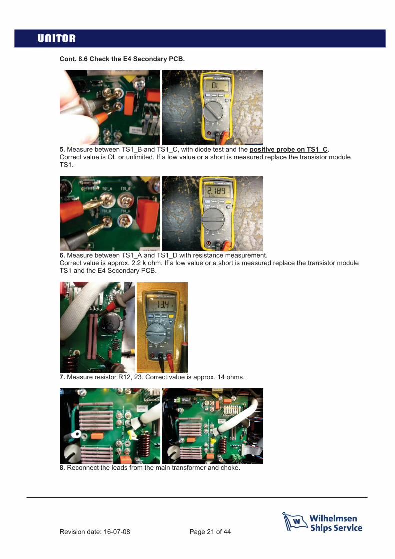
Cont. 8.6 Check the E4 Secondary PCB.
5. Measure between TS1_B and TS1_C, with diode test and the positive probe on TS1_C.Correct value is OL or unlimited. If a low value or a short is measured replace the transistor module TS1.
6. Measure between TS1_A and TS1_D with resistance measurement.Correct value is approx. 2.2 k ohm. If a low value or a short is measured replace the transistor module TS1 and the E4 Secondary PCB.
7. Measure resistor R12, 23. Correct value is approx. 14 ohms.
8. Reconnect the leads from the main transformer and choke.

Revision date: 16-07-08 Page 22 of 44
8.7 Check the K1 pressure switch and K2-4 thermostat.
1. Turn the knob on the pressure regulator CCW to its lowest setting. Connect air at 6-8 bar to theregulator. Turn the knob on the regulator CW to increase pressure setting while you measure betweencable 46 and 66 on the K1 pressure switch with resistance or buzzer measurement, at approx. 3.5 barthe K1 pressure switch should switch on.Correct value is 0 ohm.If the pressure switch doesn’t switch on replace the pressure switch.
2. Measure between pin 1-2 on the E4 secondary PCB A3 connector with resistance or buzzermeasurement. Correct value is 0 ohm.If value is high or no connection is measured then replace thermostat K4 on the secondary cooling f n.
3. Measure between pin 1-2 on the E4 secondary PCB A4 connector with resistance or buzzermeasurement. Correct value is 0 ohm.If value is high or no connection is measured then replace thermostat K2-3 on the E1 Primary cardcooling fins.

Revision date: 16-07-08 Page 23 of 44
8.8 Check the TP function
Switch off the machine with B1 main switch.
Disconnect cable no. 35 from the L3 socket.
Switch on the B1 main switch.
The TP indicator should be illuminated, if not change the TP PCB.
Switch off the machine with B1 main switch.
Reconnect cable 35 to the L3 socket.

Revision date: 16-07-08 Page 24 of 44
8.9 Check supply and system voltage.Connect the machine to mains supply.
1. Check the incoming voltage between all three phases. Correct value is 400 or 440VAC dependingon the supply voltage. If one phase is missing or low check the mains supply fuses.
Switch on the machine with B1 main switch.
2. Check the voltage on the D5 main rectifier between cable no. 73 and 74 positive probe on cable73. Correct value is approx. 620VDC if connected to 440VAC and 560VDC if connected to 400VAC. Ifvoltage is low recheck the main supply fuses, E5 EMC-Filter, B1 switch and D5 main rectifier.
1. 2.
3.

Revision date: 16-07-08 Page 25 of 44
Cont. 8.9 Check supply and system voltage
3. Check the voltages on the T1 Control transformer, between 0 and 230 on the primary side.If low or not existing check the fuse on the control transformer. If fuse is undamaged replace thecontrol transformer. If fuse is broken go to step 4.
4. If fuse is broken replace the fuse and try again. If the fuse breaks again then disconnect the fan byremoving connector A7 on the E2 Control PCB. Replace the fuse and recheck the voltage, if correctreplace the fan.
5. Check the secondary voltages on the T1 control transformer between 0 and 24VCorrect value approx 24VAC. If low replace the control transformer.
6. Check the secondary voltages on the T1 control transformer between 0 and 13.5VCorrect value approx 14VAC. If low replace the control transformer.

Revision date: 16-07-08 Page 26 of 44
Cont. 8.9 Check supply and system voltage
7. Measure the voltage between TS1_A and TS1_D on the E4 Secondary PCB.Correct value is 10VDC, if low or missing replace the E4 Secondary PCB and TS1.
8. Measure the relay inside the copper winding, between point J1 and J2.Correct value is 18VDC. If no voltage then replace the E4 Secondary PCB.
Switch off the machine with B1 main switch.
Revision date: 16-07-08 Page 27 of 44
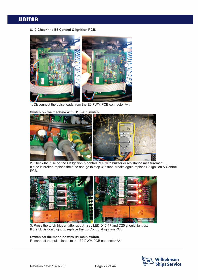
8.10 Check the E3 Control & ignition PCB.
1. Disconnect the pulse leads from the E2 PWM PCB connector A4.
Switch on the machine with B1 main switch.
2. Check the fuse on the E3 Ignition & control PCB with buzzer or resistance measurement.If fuse is broken replace the fuse and go to step 3, if fuse breaks again replace E3 Ignition & ControlPCB.
3. Press the torch trigger, after about 1sec LED D15-17 and D25 should light up.If the LEDs don’t light up replace the E3 Control & ignition PCB
Switch off the machine with B1 main switch.Reconnect the pulse leads to the E2 PWM PCB connector A4.

Revision date: 16-07-08 Page 28 of 44
8.10 Check the E2 PWM PCB.
1. Disconnect the pulse leads from the E2 PWM PCB connector A4.
Switch on the machine with B1 main switch.
2. Check the Fuse on the E2 PWM PCB with buzzer or resistance measurement.If the fuse is broken try replacing it with a new and switch on the machine. If it breaks again thenreplace the E2 PWM PCB.
3. Switch on the machine and press the torch trigger, after about 1 sec the D11 LED should light upand stay lit for about 3 sec. If D11 doesn’t light up replace the E2 PWM PCB.
Switch off the machine with B1 main switch.Reconnect the pulse leads to the E2 PWM PCB connector A4.

Revision date: 16-07-08 Page 29 of 44
8.11 Check open circuit voltage.
1. Remove jumper J1 from the E3 gnition & ontrol PCB.
Switch on the machine with B1.
2. Measure between P and minus (-) on the E4 secondary PCB with a DC voltage measurement.Press torch trigger, after approx. 1sec you should get voltage. This voltage will disappear after approx.3seconds and its then necessary to release and press torch trigger again.Correct value is approx. 240VDC.
If value is missing recheck machine most likely one step has been overlooked.
Switch off the machine with B1.Replace J1 on the E3 ignition and control PCB.

Revision date: 16-07-08 Page 30 of 44
8.12 Check E3 Control & Ignition PCB sequence.
Correct sequence:
1. Not active:None off the leds are lit
2. Pre flow:Press torch trigger, D17 lights up indicating pre flow, gas starts to flow through the system.
3. Pilot arc:After about 1sec D16 lights up indicating that the PWM PCB should start to send out pulses to theprimary PCB, and that the ignition pulses to the ignition transformer should start. Pilot arc ignites.This signal is present for approx. 3sec then the signal disappears and pilot arc is extinguished if thepilot arc doesn’t make contact with work piece.

Revision date: 16-07-08 Page 31 of 44
Cont. 8.12 Check E3 Control & Ignition PCB.
4. Main arc:When the pilot arc gets in contact with the cutting material D15 and D25 lights up indicating that thesignal for contact with material has been detected, the E3 Control & ignition PCB is activating thecutting flow, switching off pilot transistor and increasing current from pilot current to cutting current.
5. Post flow:After finished cutting cycle and release off trigger D17 and D25 remains on for approx. 30secs in orderfor the torch to cool down after finished cutting cycle.
If any discrepancies change the E3 Ignition & Control PCB.
Revision date: 16-07-08 Page 32 of 44
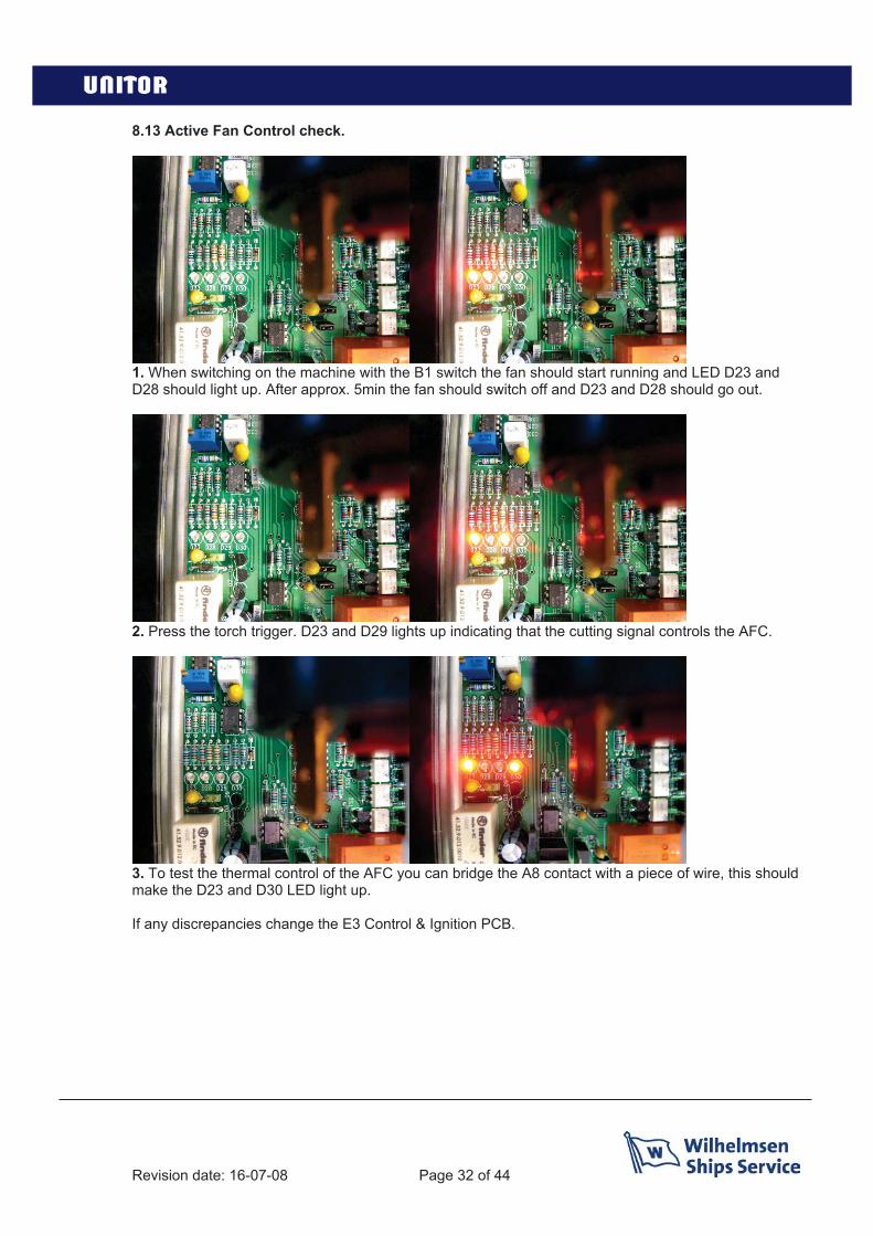
8.13 Active Fan Control check.
1. When switching on the machine with the B1 switch the fan should start running and LED D23 and D28 should light up. After approx. 5min the fan should switch off and D23 and D28 should go out.
2. Press the torch trigger. D23 and D29 lights up indicating that the cutting signal controls the AFC.
3. To test the thermal control of the AFC you can bridge the A8 contact with a piece of wire, this should make the D23 and D30 LED light up.
If any discrepancies change the E3 Control & Ignition PCB.
Revision date: 16-07-08 Page 33 of 44
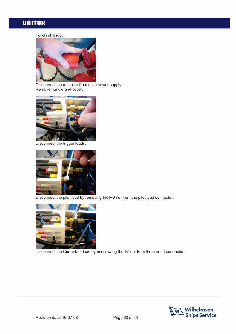
Torch change.
Disconnect the machine from main power supply.Remove handle and cover.
Disconnect the trigger leads.
Disconnect the pilot lead by removing the M6 nut from the pilot lead connector.
Disconnect the Current/air lead by unscrewing the ¼” nut from the current connector.
Revision date: 16-07-08 Page 34 of 44
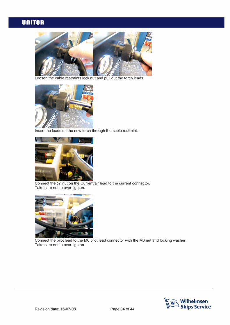
Loosen the cable restraints lock nut and pull out the torch leads.
Insert the leads on the new torch through the cable restraint.
Connect the ¼” nut on the Current/air lead to the current connector.Take care not to over tighten.
Connect the pilot lead to the M6 pilot lead connector with the M6 nut and locking washer. Take care not to over tighten.
Revision date: 16-07-08 Page 35 of 44
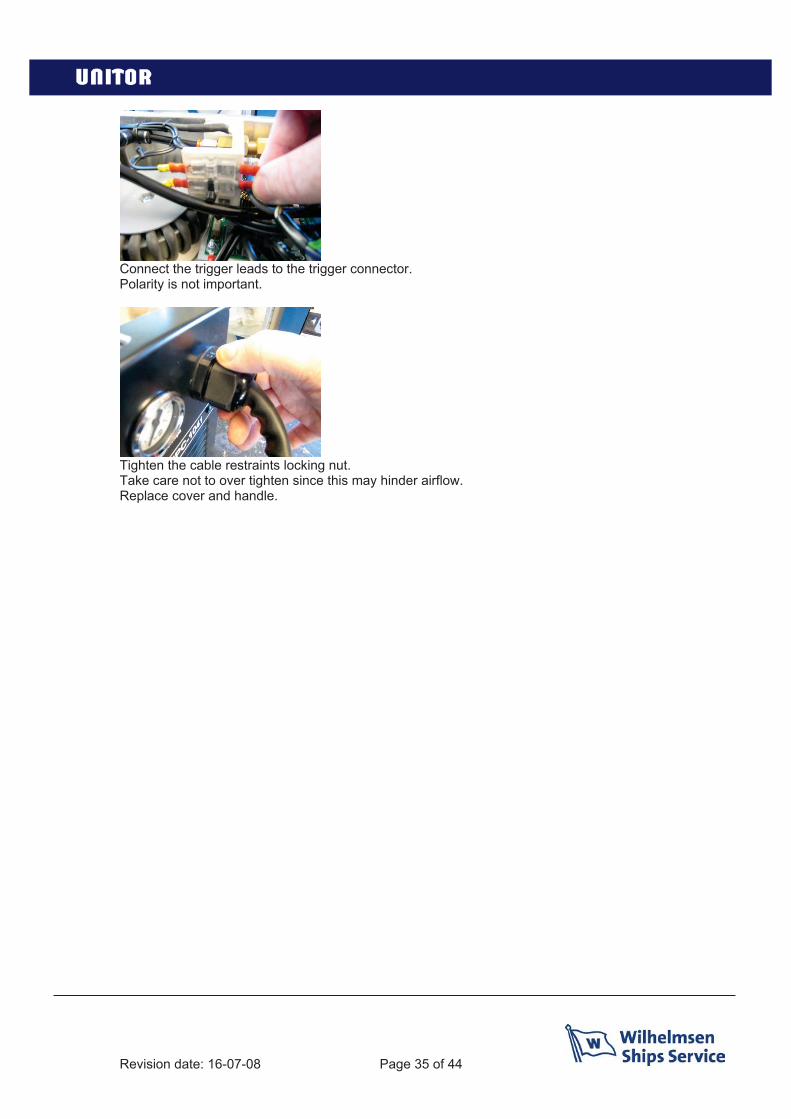
Connect the trigger leads to the trigger connector.Polarity is not important.
Tighten the cable restraints locking nut.Take care not to over tighten since this may hinder airflow.Replace cover and handle.

Page 36 of 44Revision date: 16-07-06
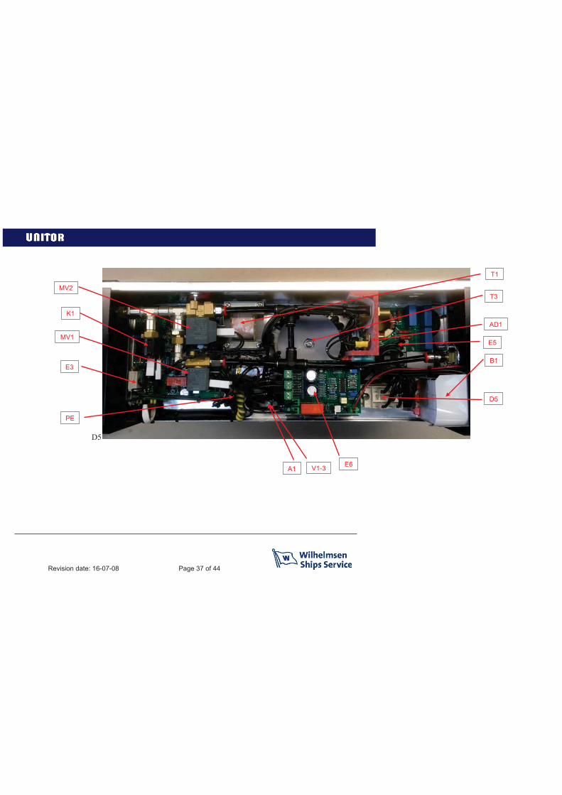
Revision date: 16-07-08 Page 37 of 44
D5
MV2
MV1
K1
E3
PE
A1 V1-3 E6
D5
B1
AD1
T3
T1
E5

Revision date: 16-07-08 Page 38 of 44
C3
C2
L2
M (Fan)
E4
C4-5
K4mounted on cooling fin
LA1
R
E2
T2-L1
E1, K2-3mounted on cooling fin
AD2
C1
Revision date: 16-07-08 Page 39 of 44
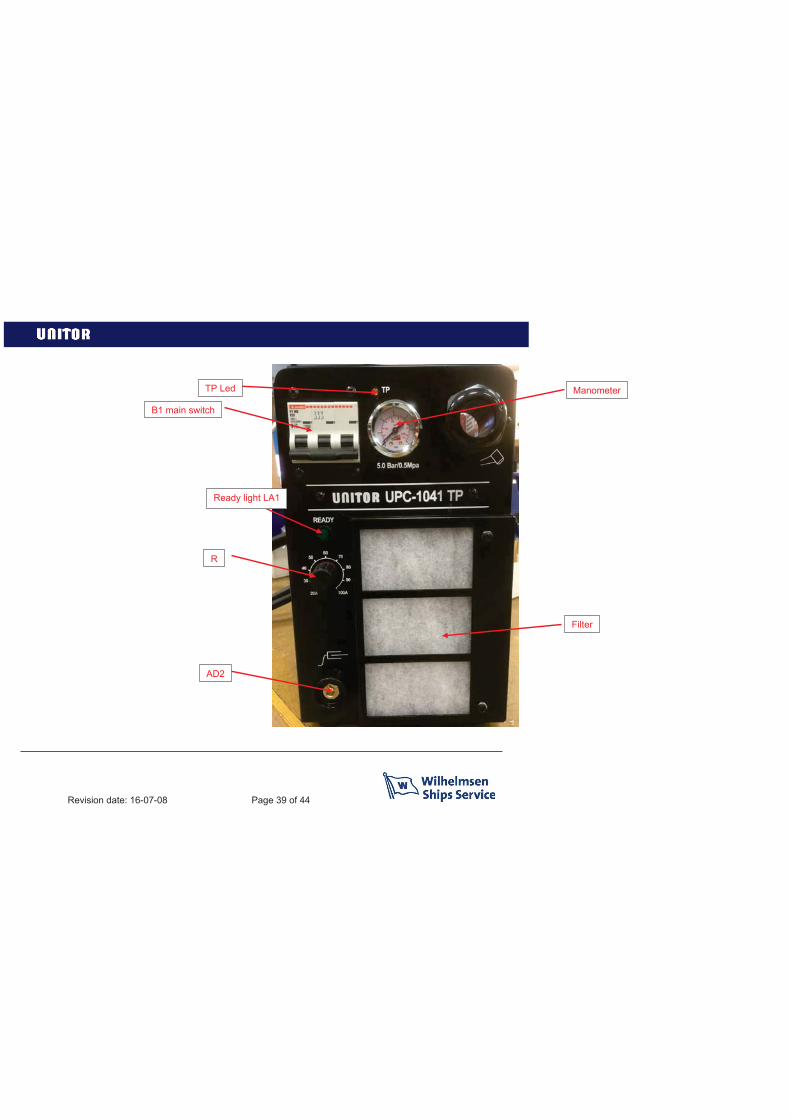
TP Led
Ready light LA1
R
AD2
Filter
Manometer
B1 main switch

Revision date: 16-07-08 Page 40 of 44

Revision date: 16-07-08 Page 41 of 44
Notes

Revision date: 16-07-08 Page 42 of 44
Notes

Revision date: 16-07-08 Page 44 of 44
Fraser/surrey Gaspe Gros Caouna Halifax Hamilton Harbour Grace Holyrood Kitimat Long Pond Marytown Montreal Nanaimo New Westminster Bc Pictou/halifax Pointe Aux Pic.quebec Port Alfred Port Cartier Port Colborne Port Hawkesbury Port Mellon Port Moody Port Of Quebec Port Weller Powell River Prince Rupert Roberts Bank Saint John Sarnia, Ontario Sept Iles Seven Islands Sorel Souris/halifax Squamish St. Catherines St.john’s, Nfld St.romuald Stephensville Summerside/halifax Three Rivers Thunder Bay Toronto alleyfield Vancouver Victoria Weymouth Windsor Yarmouth Ancud / Laitec Antofagasta Arica Caldera Concepcion Bay Coquimbo Coronel Corral Huasco Las Ventanas Lirquen Lota Penco Puerto Montt Puerto Williams Punta Arenas Quintero San Antonio San Vicente Talcahuano Tocopilla Valparaiso Antilla Bahia Honda Banes Baracoa Cabanas Caibarien Cardenas Casilda Ceiba Hueca Cienfuegos Guantanamo Guayabal Havana Isabel De Sagua Manati Mariel Media Luna Moa Nicaro Niquero Nuevitas Pilon Puerto Padre Santiago De Cuba Sigloo Genoa Finn Tanamo Tunas De Zaza Vita Balao Esmeraldas Guayaquil La Libertad Manta Puerto Bolivar Freeport/bahamas Guam Mahdia Acapulco Campeche Ciudad Del Carmen Coatzacoaloos Cozumel Dos Bocas Ensenada Guaymas La Paz Lazaro Cardenas Mazatlan Progreso Puerto Vallarta Salina Cruz Tampico Topolobampo Tuxpan Vera Cruz Bonaire Bullen Bay Curacao Aguadulce Almirante Armuelles Bahia Las Minas Balboa Cristobal Manzanillo Int.term. Vacamonte Callao Chimbote Ilo Matarani Paita Pisco Guayama Guayanilla Mayaguez Ponce San Juan Yabucoa St. Vincent Chaguaramas La Brea Point Fortin Point Lisas Pointe-a-pierre Port Of Spain Tembladora Aberdeen,wa Alameda Albany,n.y. Alexandria, Va Algiers Point Amelia Anacortes, Wa Anchorage,ak Annapolis,md Antioch Aransas Pass Tx Astoria, Or Baltimore Baton Rouge Bayonne Baytown Beaumont Bellingham, Ma Bellingham, Wa Benicia, Ca Boston, Ma Bridgeport Bridgeport, Conn Brooklyn, Ny Brownsville Tx Brunswick Brunswick, Ga ucksport,me Buras Camden Camden, Nj Cameron La Chalmette Charleston, Sc Cheasapeake Chester Chicago Claymont Convent Coos Bay, Or Corpus Chr.tx Crockett Darrow Davant Deer Park Delaware City Destrehan Donaldsonville Dutch Harbor, Ak Eastport, Me Eureka Everett, Wa Fairless Hills Famagusta Ferndale,wa Freeport Tx Galveston Tx Garyville Geismar Georgetown, Sc Gloucester, Nj Good Hope Gramercy Grand Isle Grays Harbour Gretna Gulfport, Ms Harvey Honolulu, Hawaii Hoquiam, Wa Houma Jacksonville Kalama Kalama, Wa Kenai Key West Lake Charles La Long Beach Long Island, Ny Longview, Wa Loop Terminal Los AngelesManchester, Wa Manhattan, Ny Marcus Hook, Pa Martinez Miami Mobile Morehead City Morehead City, Nc Morgan City Morrisville, Pa Myrtle Grove Naples Nederland Tx New Haven, Conn New Iberia New London New Orleans New York Newington, Nh Newport News, Va Newport, Or Newport, Ri Nikiski Norco Norfolk Oakland Olympia, Wa Orange, Rotterdam Tx Palm Beach Panama City, Fl Pasadena Pascagoula, Ms Paulsboro, Nj Pennsauken, Nj Pensacola, Fl Petaluma Philadelphia Piney Point, Md Pittsburg Plaquemine Point Comfort Tx Port Allen Port Angeles, Wa Port Arthur Tx Port Canaveral Port Everglades Port Hueneme Port Isabel Tx Port Manatee, Fl Port Neches Tx Port Royal, Sc Port St. Joe, Fl Port Townsend, Wa Portland, Me Portland, Or Portsmouth Portsmouth, Nh Providence, Ri Queens, Ny Redwood City Reserve Revere, Ma Richmond Richmond, Va Sacramento Salem Salem, Ma San Diego San Francisco Sandwich, Ma Savannah Searsport, Me Seattle Seward Sparrows Point St.petersburg, Fl St.rose Staten Island, Ny Stockton Tacoma, Wa Tampa Texas City The Bronx, Ny The Loop Valdez Vancouver, Wa Venice West Palm Beach Westville, Nj Wilmington, Ca Wilmington, De Houston Wilmington,nc Yonkers, Ny Yorktown, Va Fray Bentos Jose Ignacio Montevideo Nueva Palmira Amuay Bay Bajo Grande Cumarebo El Palito El Tablazo Guanta Guaranao Jose Bay La Guaira La Salina Maracaibo Pertigalete Puerto Cabello Puerto La Cruz Puerto Miranda Puerto Ordaz Punta Cardon Punta De Palmas Punto Fijo San Lorenzo, Vz St.croix Aeroskobing Assens Bagenkop Bogense Copenhagen Ebeltoft Enstedvaerket Havn Esbjerg Fakse Ladeplads Havn Fredericia Frederiksund Frederiksvaerk Fredrikshavn Faaborg Gedser Great Belt Grenaa Graasten Gulfhavn Haderslev Halsskov Hanstholm Helsingor Hirtshals Hobro Holbaek Horsens Kalundborg Kertminde Koge Kolding Korsor Lemvig Mariager Marstal Oslo Middlefart Naestved Nakskov Nyborg Nykobing Falster Nykobing Mors Nykobing Skjaelland Odense Orehoved Falster Randers Ronne Rudkobing Sakskobing Skaelskor Skaerbaek Skagen Skive Sonderborg Stege Stigsnaesvaerkets Havn Svendborg Studstrupvaerkets Havn Thisted Thorshavn Vejle Vordingborg Aabenraa Aalborg Aarhus Kunda Loksa Muuga Paldiski Paljassaare Parnu Tallinn Dalsbruk Hamina/fr.havn Hanko/hangoe Helsinki Ingaa/inkoo Jakobstad Kalajoki Kantvik Kaskinen/kasko Kemi Kemio Kokkola/karleby Kotka Koverhar Kristinestad Lappvik Lovisa Mariehamn Merikarvia Nystad Naantali Oulu Pargas Pori Porvoo/borgaa Rauma Raahe/brahestad Skoeldvik Tammisaari Teijo Tolkis Torneaa Turku Valkom/valko Vaasa Akureyri Isafjørdur Reykjavik Arklow Aughinish Bantry Cork Drogheda Dublin Dun Laoghaire Dundalk Foynes Galway Limerick Moneypoint Ringaskiddy Tarbert Waterford Liepaja Mersrags Riga Roja Salacgriva Skulte VentspilsButinge Klaipeda Agnefest Alta Piraeus Arendal Asker Askoy Aukra Aure Averoey Bergen Berlevaag Bodoe Boemlo Brattvag Breivika Brevik Baatsfjord Dirdal Drammen Dusavik Egersund Eide Elnesvaagen Eydehavn Fagerstrand Farsund Finnsnes Flekkefjord Floroe Flaam Fosnavaag Fraena Fredrikstad Frei Gamvik Genoa Geiranger Gjemnes Glomfjord Gravdal Grimstad Gudvangen Halden Halsa Hammerfest Harstad Haugesund Hellesylt Heroeya Hjelmeland Hoeyanger Holla Holmestrand Hommelvik Honningsvaag Horten Husnes Jelsa Jessheim Joerpeland Joessinghamn Kambo Karmoey Kirkenes Singapore Krageroe Kristiansand Kristiansund Kvinesdal Kyrksaeterora Kaarsto Larvik Leknes Lillesand Lyngdal Mandal Mehavn Mo I Rana Molde Mongstad Mosjoen Moss Muruvik Maaloey Namsos Narvik Nesset Odda Oelen Oersta Orkanger Porsgrunn Rafnes Randaberg Raubergvika Risoer Sandefjord Sandnes Sandnessjoen Sarpsborg Sauda Skien Skjervoey Slagen Slagentangen Smoela Soevik Sola Sorreisa Sortland Stavanger Stord Sture Sunndalsoera Dubai Surnadal Svelgen Svolvaer Tananger Tau Thamshamn Tingvoll Tjeldbergodden Toensberg Tofte Tomrefjord Tromsoe Trondheim Tustna Tvedestrand Tyssedal Tysvaer Ulsteinvik Vadsoe Vardoe Verdal Vik Volda Aagotnes Aaheim Aalesund Aalvik Aardal i Ryfylke Aardalstangen Gdansk Gdynia Kolobrzeg Police Swinoujscie Szczecin Arkangelsk Baltiysk De Kastri Kaliningrad Kandalaksha Kavkaz Kronshtadt Lomonosov Murmansk Nakhodka Novorossiysk Primorsk Sakhalin Sakhalin Severomorsk St. Petersburg Svetlyi Taman Temruk Temryuk Tuapse Vladivostok Vostochniy, Port Vostochnyi Vyborg Bohus Brofjorden Falkenberg Gavle Gothenburg Hallstavik Halmstad Helsingborg Hoganas Holmsund Hudiksvall Iggesund Kalmar Karlshamn Karlskrona Karlstad Koeping Landskrona Lidkoping Lilla Edet Luleaa Lysekil Malmoe Mariestad Marstrand Munkedal Norrkoeping Norrsundet Norrtalje Nynashamn Rotterdam Ornskoldsvik Oskarshamn Oxelosund Pitea ShanghaiSimrishamn Skarhamn Skelleftehamn Skutskar Slite Soderhamn Sodertalje Solvesborg Stenungsund Stockholm Stromstad Sundsvall Surte Trelleborg Uddevalla Umeaa Varberg Vastervik Vasteraas Visby Wallhamn Ystad Aberdeen Appledore Arbroath Ardersier Ardrossan Avonmouth Ayr Ballycastle Banff Barking Barnstaple Barrow In Furness Barry Barton On Humber Belfast Berwick Upon Tweed Billingham Birkenhead Blyth Boston Bowling Braefoot Bay Bridgend Bridlington Bridport Bristol Briton Ferry Brixham Bromborough Buckie Burntisland Burton Upon Stather Caernarvon Campbeltown Canvey Island Cardiff Carrickfergus Carrington Clacton On Sea Coleraine Connah’s Quay Coryton Cowes Dagenham Dartford Dartmouth Dover Dundee EasthamEllesmere Port Erith Falmouth Faversham Fawley Felixstowe Finnart Fishguard Fleetwood Flixborough Folkestone Fort William Forth FoweyFraserburgh Gainsborough Garston Gateshead Gillingham Girvan Glasgow Glasson Dock Glenrothes Gloucester Goole Gourock GrangemouthGranton Gravesend Great Yarmouth Greenhithe Greenock Grimsby Guernsey Gunness Hamble Hartlepool Harwich Hebburn HeyshamHolyhead Hull Humber Hunterstone Immingham Invergordon Inverkeithing Inverness Ipswich Irvine Isle Of Grain Jarrow Jersey Kilkeel
Instruction manual& spare part list
We service your needs in 2 200 ports…
www.wilhelmsen.com/shipsservice