Air Operated Priming System AirPrime06... · priming components must be ABOVE the highest priming...
16
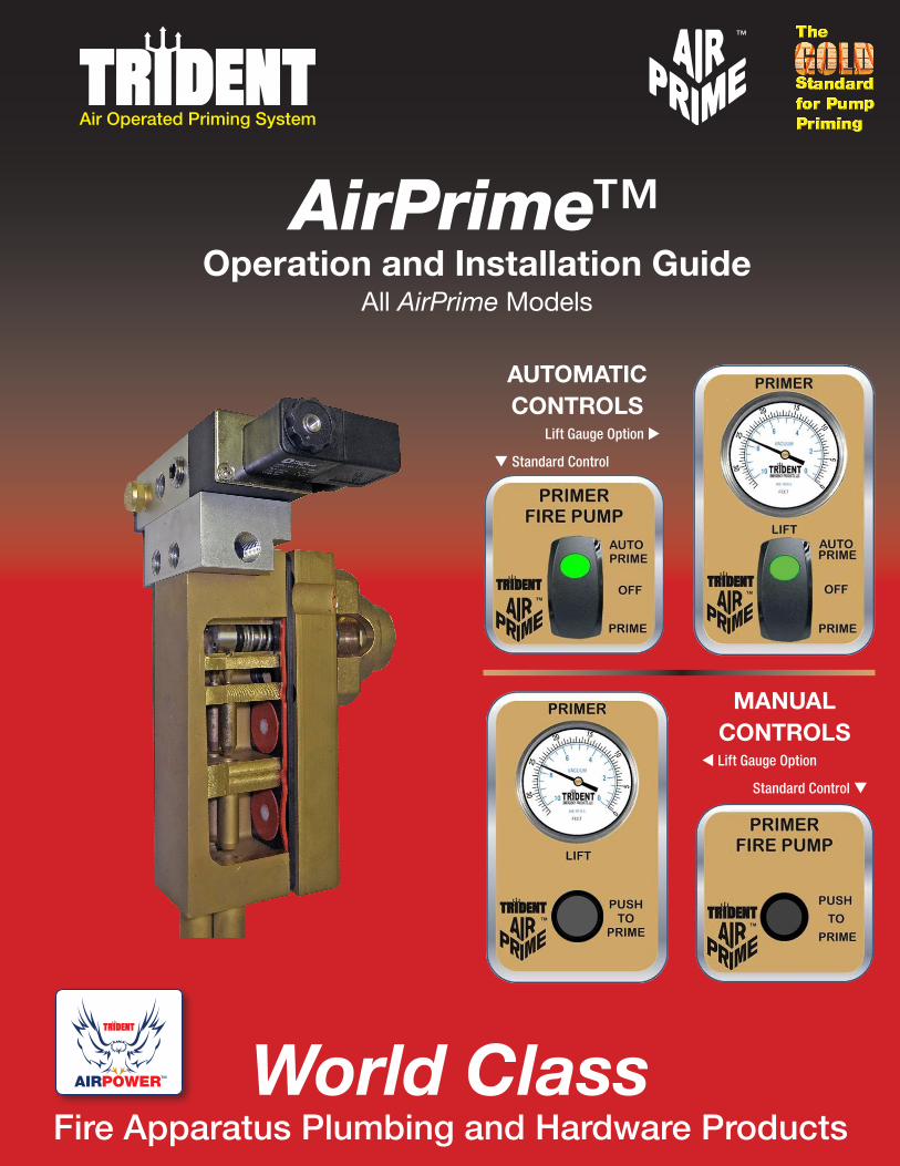
™ Air Operated Priming System AirPrime ™ Operation and Installation Guide All AirPrime Models World Class Fire Apparatus Plumbing and Hardware Products AUTOMATIC CONTROLS MANUAL CONTROLS t Lift Gauge Option Standard Control q Lift Gauge Option u q Standard Control AIRPOWER ™
Transcript of Air Operated Priming System AirPrime06... · priming components must be ABOVE the highest priming...
™
Air Operated Priming System
AirPrime™Operation and Installation Guide
All AirPrime Models
World ClassFire Apparatus Plumbing and Hardware Products
AUTOMATICCONTROLS
MANUALCONTROLS
t Lift Gauge Option
Standard Control q
Lift Gauge Option u
q Standard Control
AIRPOWER™
Trident Emergency Products, LLC2940 Turnpike Drive | Suite #9 | Hatboro, Pennsylvania 19040
2
AirPrime™ Priming System™
AirPrime™ Overview
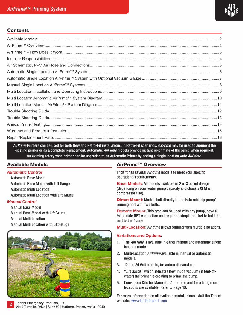
Trident has several AirPrime models to meet your specific operational requirements.
Base Models: All models available in 2 or 3 barrel design (depending on your water pump capacity and chassis CFM air compressor size).
Direct Mount: Models bolt directly to the Hale midship pump’s priming port with two bolts.
Remote Mount: This type can be used with any pump, have a 3⁄4" female NPT connection and require a simple bracket to hold the unit to the frame.
Multi-Location: AirPrime allows priming from multiple locations.
Variations and Options:
1. The AirPrime is available in either manual and automatic single location models.
2. Multi-Location AirPrime available in manual or automatic models.
3. 12 and 24 Volt models, for automatic versions.
4. “Lift Gauge” which indicates how much vacuum (in feet-of-water) the primer is creating to prime the pump.
5. Conversion Kits for Manual to Automatic and for adding more locations are available. Refer to Page 16.
For more information on all available models please visit the Trident website: www.tridentdirect.com
Contents
Available Models ��������������������������������������������������������������������������������������������������������������������������������������������������������������������2
AirPrime™ Overview ��������������������������������������������������������������������������������������������������������������������������������������������������������������2
AirPrime™ - How Does It Work ����������������������������������������������������������������������������������������������������������������������������������������������3
Installer Responsibilities ���������������������������������������������������������������������������������������������������������������������������������������������������������4
Air Schematic, PPV, Air Hose and Connections ���������������������������������������������������������������������������������������������������������������������5
Automatic Single Location AirPrime™ System ����������������������������������������������������������������������������������������������������������������������6
Automatic Single Location AirPrime™ System with Optional Vacuum Gauge ����������������������������������������������������������������������7
Manual Single Location AirPrime™ Systems �������������������������������������������������������������������������������������������������������������������������8
Multi Location Installation and Operating Instructions �����������������������������������������������������������������������������������������������������������9
Multi Location Automatic AirPrime™ System Diagram ��������������������������������������������������������������������������������������������������������10
Multi Location Manual AirPrime™ System Diagram ������������������������������������������������������������������������������������������������������������11
Trouble Shooting Guide ��������������������������������������������������������������������������������������������������������������������������������������������������������12
Trouble Shooting Guide ��������������������������������������������������������������������������������������������������������������������������������������������������������13
Annual Primer Testing �����������������������������������������������������������������������������������������������������������������������������������������������������������14
Warranty and Product Information ���������������������������������������������������������������������������������������������������������������������������������������15
Repair/Replacement Parts ���������������������������������������������������������������������������������������������������������������������������������������������������16
Available Models
Automatic ControlAutomatic Base ModelAutomatic Base Model with Lift GaugeAutomatic Multi LocationAutomatic Multi Location with Lift Gauge
Manual ControlManual Base ModelManual Base Model with Lift GaugeManual Multi LocationManual Multi Location with Lift Gauge
AirPrime Primers can be used for both New and Retro-Fit installations. In Retro-Fit scenarios, AirPrime may be used to augment the existing primer or as a complete replacement. Automatic AirPrime models provide instant re-priming of the pump when required.
An existing rotary vane primer can be upgraded to an Automatic Primer by adding a single location Auto AirPrime.
( 215-293-0700 7 [email protected]
3
Operation and Installation Manual
AirPrime™ - How Does It Work
NFPA #1901 and #1906 – Fully Compliant to StandardsPump Panel Noise Level – Lowest dB in the industry
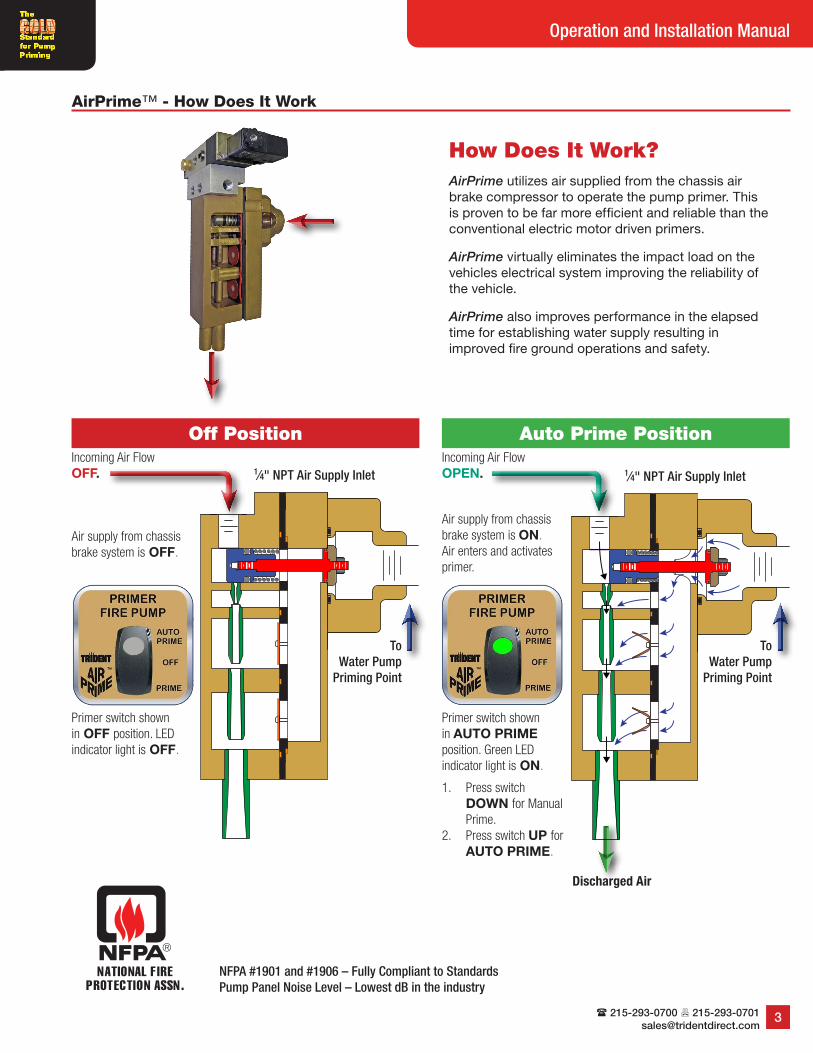
How Does It Work?AirPrime utilizes air supplied from the chassis air brake compressor to operate the pump primer� This is proven to be far more efficient and reliable than the conventional electric motor driven primers�
AirPrime virtually eliminates the impact load on the vehicles electrical system improving the reliability of the vehicle�
AirPrime also improves performance in the elapsed time for establishing water supply resulting in improved fire ground operations and safety�
Auto Prime PositionOff Position
Primer switch shown in OFF position. LED indicator light is OFF.
Primer switch shown in AUTO PRIME position. Green LED indicator light is ON.
1. Press switch DOWN for Manual Prime.
2. Press switch UP for AUTO PRIME.
1⁄4" NPT Air Supply Inlet 1⁄4" NPT Air Supply Inlet
To Water Pump
Priming Point
Discharged Air
To Water Pump
Priming Point
Air supply from chassis brake system is OFF.
Incoming Air Flow OFF.
Air supply from chassis brake system is ON. Air enters and activates primer.
Incoming Air Flow OPEN.
Trident Emergency Products, LLC2940 Turnpike Drive | Suite #9 | Hatboro, Pennsylvania 19040
4
AirPrime™ Priming System™
Installer Responsibilities
Air Compressor Size1. The 2-barrel AirPrime must be used only on fire pumps rated 1000-GPM [3800LPM] and smaller. The chassis shall be equipped with a
minimum of 13.2CFM [0.374 Cubic Meters per Minute] displacement air compressor.2. The 3-barrel AirPrime must be used only on fire pumps rated 1250-GPM [4700LPM] and larger. The chassis shall be equipped with a
minimum of 15.6CFM [0.442 Cubic Meters per Minute] displacement air compressor.NOTE: For operations above 4000 feet [1219 meters] of elevation and lifts greater than 15 feet [4.5 meters], a minimum air compressor size of larger than 18CFM [0.510 Cubic Meters per Minute] shall be required.
Basic Materials Supplied by Installer1. A 3⁄8" air hose from air tank (primary or auxiliary tank) with 1⁄4" NPT connections (length to be determined by installer).2. Primer mounting bracket. (Only required for remote mount.) See Figure #2.3. Non-collapsible 3⁄4" minimum inside diameter air hose from primer to fire pump with 3⁄4" NPT connections.4. Pressure protection valve (PPV) (Option available from Trident, Part # 30.053.0).5. A 11⁄4" [32 mm] inside diameter hose may be connected to the ‘primer outlet’ using a hose clamp to secure it in place. This hose could
direct the water that is discharged from the primer to any convenient location under the vehicle. Be sure this hose is properly secured, kept as short as possible, free of any kinks, sharp bends, and pitched to allow drainage.
6. Liquid thread sealant or Teflon tape is required for all threaded pneumatic fittings. NOTE: Use sparingly while applying sealant to avoid blockage of the air filter. See Page 5, Figure #5.
Remote Primer Mounting1. An installer supplied primer bracket shall be installed to secure the primer within the pump enclosure. The mounting height for all
priming components must be ABOVE the highest priming point on suction side of fire pump (Or above the highest remote priming valve for multiple location systems) to permit air removal and allow for complete drainage. See Figure #2 for mounting bolt hole template. NOTE: Primer must be mounted vertically.
2. Hose from the 3⁄4" NPT cleanable wye strainer on the primer inlet to the 3⁄4" NPT fire pump priming port shall be non-collapsible 3⁄4" minimum inside diameter.
3. The AirPrime and attached wye strainer shall be installed in an accessible location per Figure #3 on Page 5. The installer may choose from one of the options below as a method of draining the strainer: a) Remove threaded plug on wye strainer for draining during annual pump service. Refer to Page 13 for Troubleshooting Guide.b) For draining purposes, the strainer may be piped to the Master Drain of the fire pump system by the installer, especially in
freezing climates.c) Alternatively a separate drain with valve and label may be piped to the bottom of the pump enclosure by the installer.
NOTE: If a front suction inlet is provided, a REMOTE PRIMER mounting is required. Refer to drawings of front suction plumbing on Pages 11 and 12.
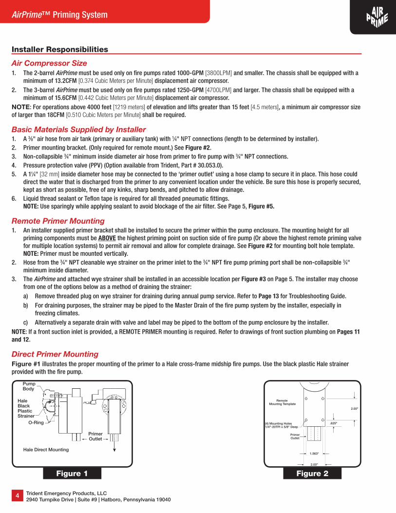
Direct Primer MountingFigure #1 illustrates the proper mounting of the primer to a Hale cross-frame midship fire pumps. Use the black plastic Hale strainer provided with the fire pump.
1.563"
2.00"
2.00"
.625"(4) Mounting Holes1/4"-20TPI x 5/8" Deep
PrimerOutlet
Remote Mountng Template
PumpBody
O-Ring
HaleBlackPlasticStrainer
PrimerOutlet
Hale Direct Mounting
Figure 2Figure 1
( 215-293-0700 7 [email protected]
5
Operation and Installation Manual
Air Schematic, PPV, Air Hose and Connections
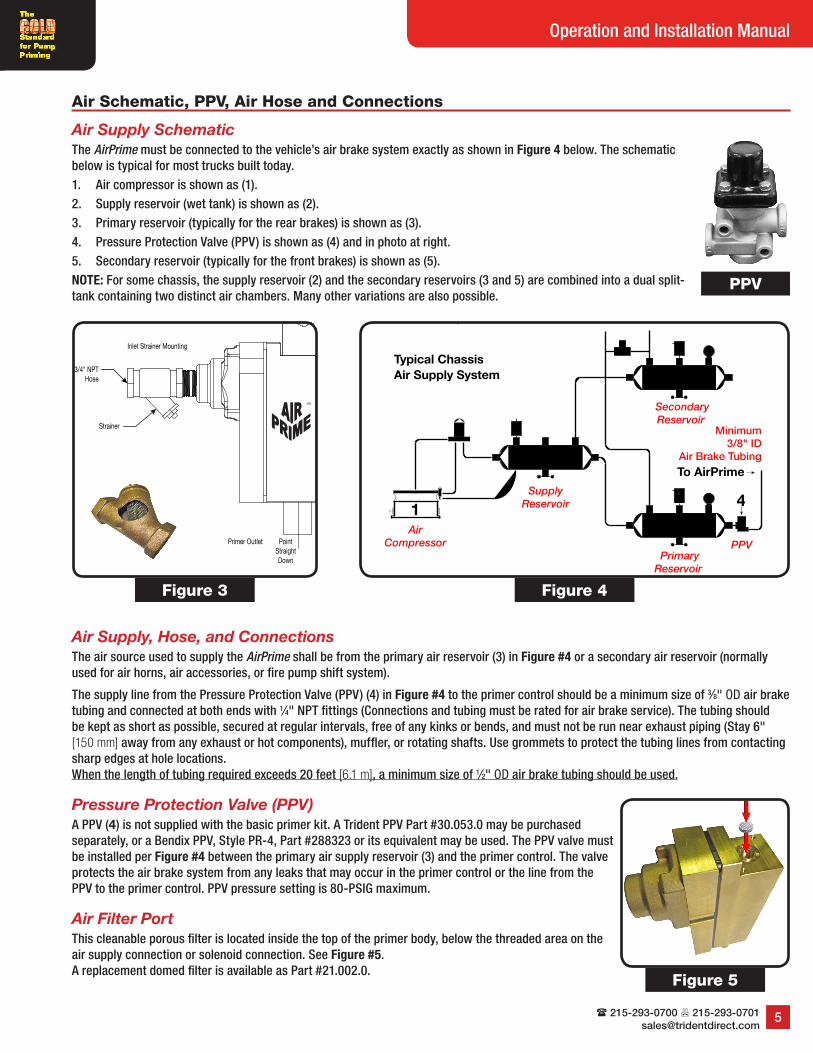
Air Supply SchematicThe AirPrime must be connected to the vehicle’s air brake system exactly as shown in Figure 4 below. The schematic below is typical for most trucks built today.1. Air compressor is shown as (1).2. Supply reservoir (wet tank) is shown as (2).3. Primary reservoir (typically for the rear brakes) is shown as (3).4. Pressure Protection Valve (PPV) is shown as (4) and in photo at right.5. Secondary reservoir (typically for the front brakes) is shown as (5).NOTE: For some chassis, the supply reservoir (2) and the secondary reservoirs (3 and 5) are combined into a dual split-tank containing two distinct air chambers. Many other variations are also possible.
Air Supply, Hose, and ConnectionsThe air source used to supply the AirPrime shall be from the primary air reservoir (3) in Figure #4 or a secondary air reservoir (normally used for air horns, air accessories, or fire pump shift system).
The supply line from the Pressure Protection Valve (PPV) (4) in Figure #4 to the primer control should be a minimum size of 3⁄8" OD air brake tubing and connected at both ends with 1⁄4" NPT fittings (Connections and tubing must be rated for air brake service). The tubing should be kept as short as possible, secured at regular intervals, free of any kinks or bends, and must not be run near exhaust piping (Stay 6" [150 mm] away from any exhaust or hot components), muffler, or rotating shafts. Use grommets to protect the tubing lines from contacting sharp edges at hole locations. When the length of tubing required exceeds 20 feet [6.1 m], a minimum size of 1⁄2" OD air brake tubing should be used.
Pressure Protection Valve (PPV)A PPV (4) is not supplied with the basic primer kit. A Trident PPV Part #30.053.0 may be purchased separately, or a Bendix PPV, Style PR-4, Part #288323 or its equivalent may be used. The PPV valve must be installed per Figure #4 between the primary air supply reservoir (3) and the primer control. The valve protects the air brake system from any leaks that may occur in the primer control or the line from the PPV to the primer control. PPV pressure setting is 80-PSIG maximum.
Air Filter PortThis cleanable porous filter is located inside the top of the primer body, below the threaded area on the air supply connection or solenoid connection. See Figure #5. A replacement domed filter is available as Part #21.002.0.
1
2
34
5
To AirPrime
Typical Chassis
Air Supply System
AirCompressor
PrimaryReservoir
SecondaryReservoir
PPV
SupplyReservoir
Minimum 3/8" ID
Air Brake Tubing
Figure 4
3/4" NPTHose
Strainer
Inlet Strainer Mounting
™
PointStraightDown
Primer Outlet
Figure 3
PPV
Figure 5
Trident Emergency Products, LLC2940 Turnpike Drive | Suite #9 | Hatboro, Pennsylvania 19040
6
AirPrime™ Priming System™
Automatic Single Location AirPrime™ System
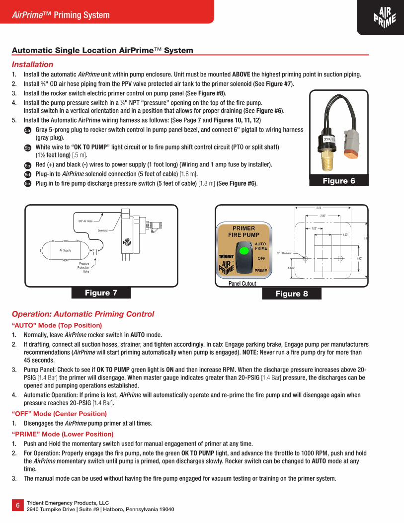
Installation1. Install the automatic AirPrime unit within pump enclosure. Unit must be mounted ABOVE the highest priming point in suction piping.2. Install 3⁄8" OD air hose piping from the PPV valve protected air tank to the primer solenoid (See Figure #7).3. Install the rocker switch electric primer control on pump panel (See Figure #8).4. Install the pump pressure switch in a 1⁄4" NPT “pressure” opening on the top of the fire pump.
Install switch in a vertical orientation and in a position that allows for proper draining (See Figure #6).5. Install the Automatic AirPrime wiring harness as follows: (See Page 7 and Figures 10, 11, 12)
Gray 5-prong plug to rocker switch control in pump panel bezel, and connect 6" pigtail to wiring harness (gray plug).White wire to “OK TO PUMP” light circuit or to fire pump shift control circuit (PTO or split shaft) (11⁄2 feet long) [.5 m].Red (+) and black (-) wires to power supply (1 foot long) (Wiring and 1 amp fuse by installer).Plug-in to AirPrime solenoid connection (5 feet of cable) [1.8 m].Plug in to fire pump discharge pressure switch (5 feet of cable) [1.8 m] (See Figure #6).
Operation: Automatic Priming Control“AUTO” Mode (Top Position)1. Normally, leave AirPrime rocker switch in AUTO mode.2. If drafting, connect all suction hoses, strainer, and tighten accordingly. In cab: Engage parking brake, Engage pump per manufacturers
recommendations (AirPrime will start priming automatically when pump is engaged). NOTE: Never run a fire pump dry for more than 45 seconds.
3. Pump Panel: Check to see if OK TO PUMP green light is ON and then increase RPM. When the discharge pressure increases above 20-PSIG [1.4 Bar] the primer will disengage. When master gauge indicates greater than 20-PSIG [1.4 Bar] pressure, the discharges can be opened and pumping operations established.
4. Automatic Operation: If prime is lost, AirPrime will automatically operate and re-prime the fire pump and will disengage again when pressure reaches 20-PSIG [1.4 Bar].
“OFF” Mode (Center Position)1. Disengages the AirPrime pump primer at all times.
“PRIME” Mode (Lower Position)1. Push and Hold the momentary switch used for manual engagement of primer at any time.2. For Operation: Properly engage the fire pump, note the green OK TO PUMP light, and advance the throttle to 1000 RPM, push and hold
the AirPrime momentary switch until pump is primed, open discharges slowly. Rocker switch can be changed to AUTO mode at any time.
3. The manual mode can be used without having the fire pump engaged for vacuum testing or training on the primer system.
2.00"
Panel Cutout
.281" Diameter
1.00"
1.00"
1.50"
3.22"
1.125"
3.22
Figure 7 Figure 8
PressureProtection
Valve
Air Supply
3/8" Air Hose
Solenoid
™
5a
5b
5c
5d
5e Figure 6
( 215-293-0700 7 [email protected]
7
Operation and Installation Manual
5.22"
1.50"
2.00"1.00"
2.50"
2.38"
1.125"
.281" Hole
Panel Cutout
3.22"
1.00"
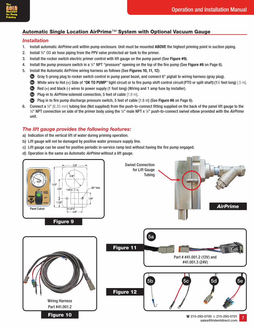
Automatic Single Location AirPrime™ System with Optional Vacuum Gauge
Installation1. Install automatic AirPrime unit within pump enclosure. Unit must be mounted ABOVE the highest priming point in suction piping.2. Install 3⁄8" OD air hose piping from the PPV valve protected air tank to the primer.3. Install the rocker switch electric primer control with lift gauge on the pump panel (See Figure #9).4. Install the pump pressure switch in a 1⁄4" NPT “pressure” opening on the top of the fire pump (See Figure #6 on Page 6).5. Install the Automatic AirPrime wiring harness as follows (See Figures 10, 11, 12):
Gray 5-prong plug to rocker switch control in pump panel bezel, and connect 6" pigtail to wiring harness (gray plug).White wire to Hot (+) Side of “OK TO PUMP” light circuit or to fire pump shift control circuit (PTO or split shaft) (11⁄2 feet long) [.5 m].Red (+) and black (-) wires to power supply (1 foot long) (Wiring and 1 amp fuse by installer).Plug-in to AirPrime solenoid connection, 5 feet of cable [1.8 m].Plug in to fire pump discharge pressure switch, 5 feet of cable [1.8 m] (See Figure #6 on Page 6).
6. Connect a 1⁄4" [6.35 mm] tubing line (Not supplied) from the push-to-connect fitting supplied on the back of the panel lift gauge to the 1⁄8" NPT connection on side of the primer body using the 1⁄8" male NPT x 1⁄4" push-to-connect swivel elbow provided with the AirPrime unit.
Figure 9
Figure 11
Figure 12
Wiring HarnessPart #41.001.2
Figure 10
5b 5c 5d 5e
5a
Part # #41.001.2 (12V) and #41.001.3 (24V)
The lift gauge provides the following features:a) Indication of the vertical lift of water during priming operation.b) Lift gauge will not be damaged by positive water pressure supply line.c) Lift gauge can be used for positive periodic in-service ramp test without having the fire pump engaged.d) Operation is the same as Automatic AirPrime without a lift gauge.
Swivel Connection for Lift Gauge
Tubing
5a
5b
5c
5d
5e
AirPrime
Trident Emergency Products, LLC2940 Turnpike Drive | Suite #9 | Hatboro, Pennsylvania 19040
8
AirPrime™ Priming System™
5.22"
2.00"1.00"
2.50"
2.38"
1.125"
.281" Hole
Panel Cutout
3.22"
.781"
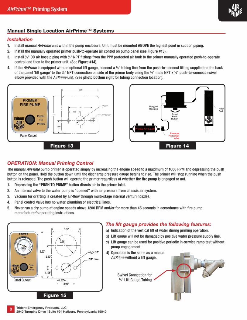
Manual Single Location AirPrime™ Systems
Installation1. Install manual AirPrime unit within the pump enclosure. Unit must be mounted ABOVE the highest point in suction piping.2. Install the manually operated primer push-to-operate air control on pump panel (see Figure #13).3. Install 3⁄8" OD air hose piping with 1⁄4" NPT fittings from the PPV protected air tank to the primer manually operated push-to-operate
control and then to the primer unit. (See Figure #14).4. If the AirPrime is equipped with an optional lift gauge, connect a 1⁄4" tubing line from the push-to-connect fitting supplied on the back
of the panel ‘lift gauge’ to the 1⁄8" NPT connection on side of the primer body using the 1⁄8" male NPT x 1⁄4" push-to-connect swivel elbow provided with the AirPrime unit. (See photo bottom right for tubing connection location).
2.00"
Panel Cutout
.281" Diameter
.781"
1.00"
3.22"
3.22
1.125"
OPERATION: Manual Priming ControlThe manual AirPrime pump primer is operated simply by increasing the engine speed to a maximum of 1000 RPM and depressing the push button on the panel. Hold the button down until the discharge pressure gauge begins to rise. The primer will stop running when the push button is released. The push button will operate the primer regardless of whether the fire pump is engaged or not.1. Depressing the “PUSH TO PRIME” button directs air to the primer inlet.2. An internal valve to the water pump is “opened” with air pressure from chassis air system.3. Vacuum for drafting is created by air-flow through multi-stage internal venturi nozzles.4. Panel control valve has no water, plumbing or electrical lines.5. Never run a dry pump at engine speeds above 1200 RPM and/or for more than 45 seconds in accordance with fire pump
manufacturer's operating instructions.
Figure 13 Figure 14
Primary Air Supply
PanelPush
Button™
PressureProtection
Valve
PluggedOpening Filter
Port
Figure 15
The lift gauge provides the following features:a) Indication of the vertical lift of water during priming operation.b) Lift gauge will not be damaged by positive water pressure supply line.c) Lift gauge can be used for positive periodic in-service ramp test without
pump engagement.d) Operation is the same as a manual
AirPrime without a lift gauge.
Swivel Connection for 1⁄4" Lift Gauge Tubing
( 215-293-0700 7 [email protected]
9
Operation and Installation Manual
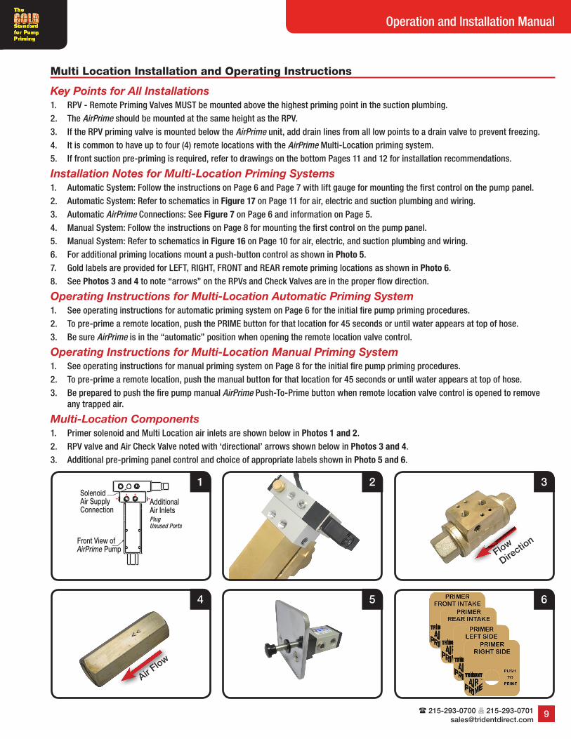
Multi Location Installation and Operating Instructions
Key Points for All Installations1. RPV - Remote Priming Valves MUST be mounted above the highest priming point in the suction plumbing.2. The AirPrime should be mounted at the same height as the RPV.3. If the RPV priming valve is mounted below the AirPrime unit, add drain lines from all low points to a drain valve to prevent freezing.4. It is common to have up to four (4) remote locations with the AirPrime Multi-Location priming system.5. If front suction pre-priming is required, refer to drawings on the bottom Pages 11 and 12 for installation recommendations.
Installation Notes for Multi-Location Priming Systems1. Automatic System: Follow the instructions on Page 6 and Page 7 with lift gauge for mounting the first control on the pump panel.2. Automatic System: Refer to schematics in Figure 17 on Page 11 for air, electric and suction plumbing and wiring.3. Automatic AirPrime Connections: See Figure 7 on Page 6 and information on Page 5.4. Manual System: Follow the instructions on Page 8 for mounting the first control on the pump panel.5. Manual System: Refer to schematics in Figure 16 on Page 10 for air, electric, and suction plumbing and wiring.6. For additional priming locations mount a push-button control as shown in Photo 5.7. Gold labels are provided for LEFT, RIGHT, FRONT and REAR remote priming locations as shown in Photo 6.8. See Photos 3 and 4 to note “arrows” on the RPVs and Check Valves are in the proper flow direction.
Operating Instructions for Multi-Location Automatic Priming System1. See operating instructions for automatic priming system on Page 6 for the initial fire pump priming procedures.2. To pre-prime a remote location, push the PRIME button for that location for 45 seconds or until water appears at top of hose.3. Be sure AirPrime is in the “automatic” position when opening the remote location valve control.
Operating Instructions for Multi-Location Manual Priming System1. See operating instructions for manual priming system on Page 8 for the initial fire pump priming procedures.2. To pre-prime a remote location, push the manual button for that location for 45 seconds or until water appears at top of hose.3. Be prepared to push the fire pump manual AirPrime Push-To-Prime button when remote location valve control is opened to remove
any trapped air.
Multi-Location Components1. Primer solenoid and Multi Location air inlets are shown below in Photos 1 and 2.2. RPV valve and Air Check Valve noted with ‘directional’ arrows shown below in Photos 3 and 4.3. Additional pre-priming panel control and choice of appropriate labels shown in Photo 5 and 6.
Front View ofAirPrime Pump
Additional Air InletsPlug Unused Ports
SolenoidAir SupplyConnection
1 2 3
4 5 6
Flow
Directio
n
Air Flow
Trident Emergency Products, LLC2940 Turnpike Drive | Suite #9 | Hatboro, Pennsylvania 19040
10
AirPrime™ Priming System™
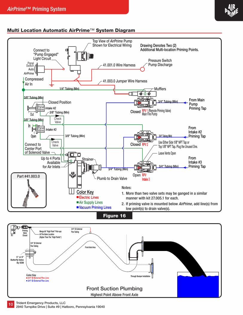
Multi Location Automatic AirPrime™ System Diagram
Compressed Air In
AutoAirPrime
Pressure SwitchPump Discharge
41.003.0 Jumper Wire Harness
41.001.0 Wire Harness
Connect to "Pump Engaged"Light Circuit
Top View of AirPrime PumpShown for Electrical Wiring
Strainer
OpenPlumb to Drain Valve
Closed
Leave Vents Open
Connect to Center Portof Solenoid Valve
RPVIntake 3
3/4" Tubing (Min)
3/4" Tubing (Min)
From Intake #2Priming Tap
From Intake #3Priming Tap
Intake #3In
Up to 4 PortsAvailable
for Air Inlets
Intake #2
From Main PumpPriming Tap
Muf�ers
Use Either Side 1/8" NPT Tap orTop 1/8" NPT Tap. Plug the Unused One.
Panel Valve
Closed Position
Open
Panel Valve
RPV 2
RPV 1 (Remote Priming Valve)Main Fire PumpClosed
CheckValve
Color Key Electric Lines Air Supply Lines Vacuum Priming Lines
3/4" Tubing (Min)
1/4" Tubing (Min)
3/8" Tubing (Min)
3/8" Tubing (Min)
3/8" Tubing (Min)3/4" Tubing (Min)
3/8" Tubing (Min)
Drawing Denotes Two (2) Additional Multi-location Priming Points.
CheckValve
PanelSwitch
™
Out
Figure 16
™
Color Key 3/4" ID External Flex Line 3/4" ID External Flex Line
3/4" ID ExternalFlex Tubing
Merge All "High Point" Pick-upsAt The Valve Location (Higher Than The "High Points")
PrimingValve
Closed
5" or 6"Butter�y Valve
By OEM
Front Axle Area
3/4" ID ExternalFlex Tubing
Through Bumper Installation
Notes:1. More than two valve sets may be ganged in a similar
manner with kit 27.005.1 for each.2. If priming valve is mounted below AirPrime, add line(s) from
low point(s) to drain valve(s).
Front Suction PlumbingHighest Point Above Front Axle
Part #41.003.0
( 215-293-0700 7 [email protected]
11
Operation and Installation Manual
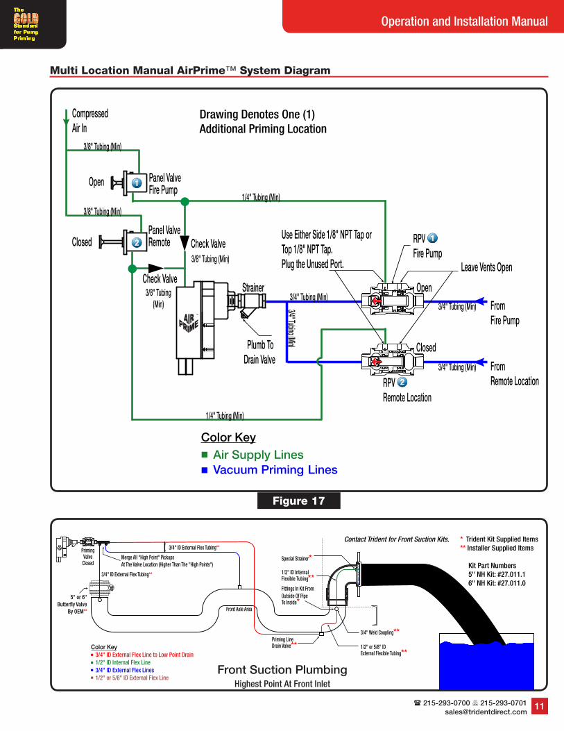
Multi Location Manual AirPrime™ System Diagram
Figure 17
™
3/4" Tubing (Min)
Plumb To Drain Valve
Use Either Side 1/8" NPT Tap orTop 1/8" NPT Tap. Plug the Unused Port.
Strainer
3/8" Tubing (Min)
3/8" Tubing(Min)
1/4" Tubing (Min)
3/8" Tubing (Min)
Check Valve
From Fire Pump
RPV Fire Pump
Open
3/4" Tubing (Min)
Leave Vents Open
Closed
CompressedAir In
From Remote Location
Panel ValveFire Pump
RPV Remote Location
Open
Closed
1/4" Tubing (Min)
3/8" Tubing (Min)
3/4" Tubing (Min)
3/4" Tubing (Min)
Check Valve
Color Key Air Supply Lines Vacuum Priming Lines
Panel ValveRemote
Drawing Denotes One (1) Additional Priming Location
™
Color Key3/4" ID External Flex Line to Low Point Drain1/2" ID Internal Flex Line3/4" ID External Flex Lines1/2" or 5/8" ID External Flex Line
1/2" ID Internal Flexible Tubing**
Priming LineDrain Valve** 1/2" or 5/8" ID
External Flexible Tubing**
3/4" Weld Coupling**
3/4" ID External Flex Tubing**
Merge All "High Point" PickupsAt The Valve Location (Higher Than The "High Points")
Fittings In Kit From Outside Of Pipe To Inside*
PrimingValve
Closed
5" or 6"Butter�y Valve
By OEM** Front Axle Area
3/4" ID External Flex Tubing**
Special Strainer*
* Trident Kit Supplied Items** Installer Supplied Items
Kit Part Numbers5" NH Kit: #27.011.16" NH Kit: #27.011.0
Contact Trident for Front Suction Kits.
Front Suction PlumbingHighest Point At Front Inlet
Trident Emergency Products, LLC2940 Turnpike Drive | Suite #9 | Hatboro, Pennsylvania 19040
12
AirPrime™ Priming System™
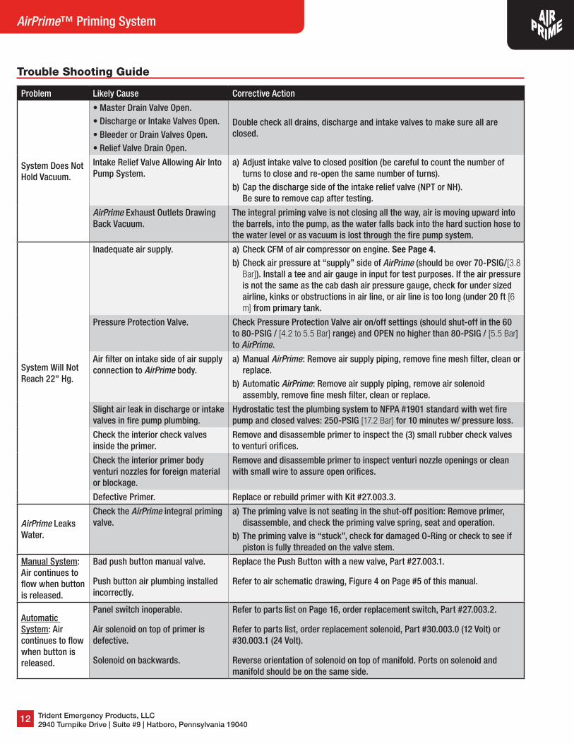
Trouble Shooting Guide
Problem Likely Cause Corrective Action
System Does Not Hold Vacuum.
• Master Drain Valve Open.• Discharge or Intake Valves Open.• Bleeder or Drain Valves Open.• Relief Valve Drain Open.
Double check all drains, discharge and intake valves to make sure all are closed.
Intake Relief Valve Allowing Air Into Pump System.
a) Adjust intake valve to closed position (be careful to count the number of turns to close and re-open the same number of turns).
b) Cap the discharge side of the intake relief valve (NPT or NH). Be sure to remove cap after testing.
AirPrime Exhaust Outlets Drawing Back Vacuum.
The integral priming valve is not closing all the way, air is moving upward into the barrels, into the pump, as the water falls back into the hard suction hose to the water level or as vacuum is lost through the fire pump system.
System Will Not Reach 22" Hg.
Inadequate air supply. a) Check CFM of air compressor on engine. See Page 4.b) Check air pressure at “supply” side of AirPrime (should be over 70-PSIG/[3.8
Bar]). Install a tee and air gauge in input for test purposes. If the air pressure is not the same as the cab dash air pressure gauge, check for under sized airline, kinks or obstructions in air line, or air line is too long (under 20 ft [6 m] from primary tank.
Pressure Protection Valve. Check Pressure Protection Valve air on/off settings (should shut-off in the 60 to 80-PSIG / [4.2 to 5.5 Bar] range) and OPEN no higher than 80-PSIG / [5.5 Bar] to AirPrime.
Air filter on intake side of air supply connection to AirPrime body.
a) Manual AirPrime: Remove air supply piping, remove fine mesh filter, clean or replace.
b) Automatic AirPrime: Remove air supply piping, remove air solenoid assembly, remove fine mesh filter, clean or replace.
Slight air leak in discharge or intake valves in fire pump plumbing.
Hydrostatic test the plumbing system to NFPA #1901 standard with wet fire pump and closed valves: 250-PSIG [17.2 Bar] for 10 minutes w/ pressure loss.
Check the interior check valves inside the primer.
Remove and disassemble primer to inspect the (3) small rubber check valves to venturi orifices.
Check the interior primer body venturi nozzles for foreign material or blockage.
Remove and disassemble primer to inspect venturi nozzle openings or clean with small wire to assure open orifices.
Defective Primer. Replace or rebuild primer with Kit #27.003.3.
AirPrime Leaks Water.
Check the AirPrime integral priming valve.
a) The priming valve is not seating in the shut-off position: Remove primer, disassemble, and check the priming valve spring, seat and operation.
b) The priming valve is “stuck”, check for damaged O-Ring or check to see if piston is fully threaded on the valve stem.
Manual System: Air continues to flow when button is released.
Bad push button manual valve.
Push button air plumbing installed incorrectly.
Replace the Push Button with a new valve, Part #27.003.1.
Refer to air schematic drawing, Figure 4 on Page #5 of this manual.
Automatic System: Air continues to flow when button is released.
Panel switch inoperable.
Air solenoid on top of primer is defective.
Solenoid on backwards.
Refer to parts list on Page 16, order replacement switch, Part #27.003.2.
Refer to parts list, order replacement solenoid, Part #30.003.0 (12 Volt) or #30.003.1 (24 Volt).
Reverse orientation of solenoid on top of manifold. Ports on solenoid and manifold should be on the same side.

( 215-293-0700 7 [email protected]
13
Operation and Installation Manual
Trouble Shooting Guide
Problem Likely Cause Corrective Action
Slow Prime Time.
Leaking air into the plumbing system.
Double check all drains, discharge, and intake valves to make sure all are closed.
Low air pressure. Check air pressure at “supply” side of AirPrime (Should be over 70-PSIG/[3.8 Bar]). Install a tee and air gauge in input for test purposes. If the air pressure is not the same as the cab dash air pressure gauge, check for an under sized airline, kinks or obstructions in air line. Or the air line may be too long (Must be under 20 feet [6 m] from primary tank).
Pressure Protection Valve. Check Pressure Protection Valve air on/off settings (should shut-off in 60 to 80-PSIG / [4.2 to 5.5 Bar] range) and OPEN no higher than 80-PSIG / [5.5 Bar] to AirPrime.
Check wye strainer on intake from fire pump, could be clogged.
a) Remote primer installation: The line from the fire pump to the AirPrime has a wye type strainer just before connecting into the primer body. Remove the plug, then strainer, and clean the strainer of debris, reinstall strainer and plug.
b) Direct mount on Hale pump installation: Remove the primer from the Hale fire pump, check the black plastic strainer (Supplied by Hale).
Check Air line to the AirPrime.
The air supply line from the air tank is either “kinked”, undersized or over length. Replace air line accordingly (NOTE: Found mainly on new installations).
Check discharge and intake valves.
Cap or plug the discharge and intake valves to prove the valves are not leaking air into the plumbing system (Hydro-static pump test is useful for such testing).
Check gated Master Intake Valves on suction intakes.
a) Remove the MIV and cap intake.b) Install a cap on the discharge side of the relief valve.c) Cap the Storz or NH intake.
Check the AirPrime integral priming valve.
a) The priming valve is not seating in the shut-off position, remove primer, disassemble, and check the priming valve spring, seat, and operation.
b) The priming valve is “stuck”, check for damaged O-Ring or check to see that the piston is still fully threaded on the valve stem.
Suction lift too high. Do not attempt lifts exceeding 24 feet.
Blocked suction strainer. Remove any obstructions or debris from hose strainer, do not allow suction hose or strainer to rest on the bottom of water supply.
Leaking Suction Hose connections.
Clean and tighten all suction hose connections, check hose washers and replace as necessary.
Air Trap in suction line. Suction hose should be positioned with a constant decline to the water supply. If a trap is unavoidable, repeated priming may be required to eliminate air pocket.
Multi Location Specific
Problem Likely Cause Corrective Action
Trouble Priming or Pre-Priming from Locations Other Than Pump.
Not priming from highest suction plumbing point.
Check suction plumbing elevations, shown on bottom of Pages 10 and 11. Check for changes in suction high point when truck is drafting on an incline.
Remote Priming Valve not opening.
Defective RPV, defective panel push button, check system plumbing using schematics on Page 10 (Automatic) Figure 16 and Page 11 (Manual) Figure 17.
Water trap in RPV line. Lines must ascend from highest suction plumbing points to RPV(s) for natural drainage and to avoid water traps.
Trident Emergency Products, LLC2940 Turnpike Drive | Suite #9 | Hatboro, Pennsylvania 19040
14
AirPrime™ Priming System™
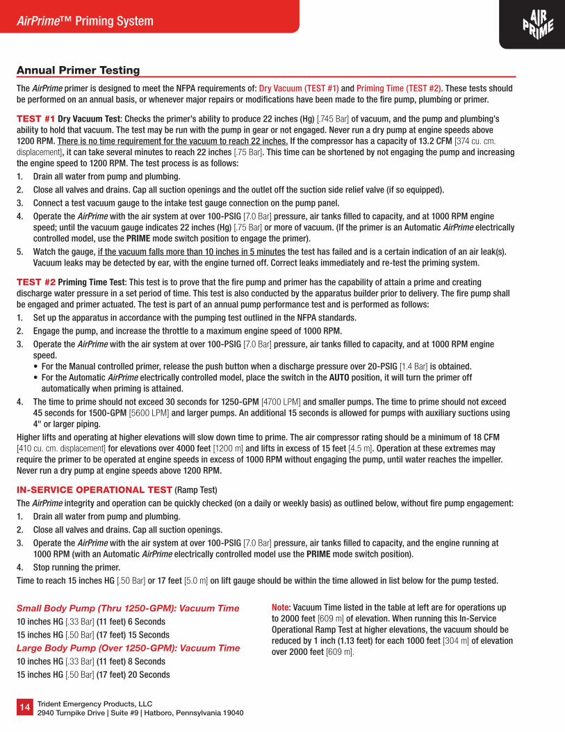
Annual Primer Testing
The AirPrime primer is designed to meet the NFPA requirements of: Dry Vacuum (TEST #1) and Priming Time (TEST #2). These tests should be performed on an annual basis, or whenever major repairs or modifications have been made to the fire pump, plumbing or primer.
TEST #1 Dry Vacuum Test: Checks the primer’s ability to produce 22 inches (Hg) [.745 Bar] of vacuum, and the pump and plumbing’s ability to hold that vacuum. The test may be run with the pump in gear or not engaged. Never run a dry pump at engine speeds above 1200 RPM. There is no time requirement for the vacuum to reach 22 inches. If the compressor has a capacity of 13.2 CFM [374 cu. cm. displacement], it can take several minutes to reach 22 inches [.75 Bar]. This time can be shortened by not engaging the pump and increasing the engine speed to 1200 RPM. The test process is as follows:1. Drain all water from pump and plumbing.2. Close all valves and drains. Cap all suction openings and the outlet off the suction side relief valve (if so equipped).3. Connect a test vacuum gauge to the intake test gauge connection on the pump panel.4. Operate the AirPrime with the air system at over 100-PSIG [7.0 Bar] pressure, air tanks filled to capacity, and at 1000 RPM engine
speed; until the vacuum gauge indicates 22 inches (Hg) [.75 Bar] or more of vacuum. (If the primer is an Automatic AirPrime electrically controlled model, use the PRIME mode switch position to engage the primer).
5. Watch the gauge, if the vacuum falls more than 10 inches in 5 minutes the test has failed and is a certain indication of an air leak(s). Vacuum leaks may be detected by ear, with the engine turned off. Correct leaks immediately and re-test the priming system.
TEST #2 Priming Time Test: This test is to prove that the fire pump and primer has the capability of attain a prime and creating discharge water pressure in a set period of time. This test is also conducted by the apparatus builder prior to delivery. The fire pump shall be engaged and primer actuated. The test is part of an annual pump performance test and is performed as follows:1. Set up the apparatus in accordance with the pumping test outlined in the NFPA standards.2. Engage the pump, and increase the throttle to a maximum engine speed of 1000 RPM.3. Operate the AirPrime with the air system at over 100-PSIG [7.0 Bar] pressure, air tanks filled to capacity, and at 1000 RPM engine
speed.• For the Manual controlled primer, release the push button when a discharge pressure over 20-PSIG [1.4 Bar] is obtained.• For the Automatic AirPrime electrically controlled model, place the switch in the AUTO position, it will turn the primer off
automatically when priming is attained.4. The time to prime should not exceed 30 seconds for 1250-GPM [4700 LPM] and smaller pumps. The time to prime should not exceed
45 seconds for 1500-GPM [5600 LPM] and larger pumps. An additional 15 seconds is allowed for pumps with auxiliary suctions using 4" or larger piping.
Higher lifts and operating at higher elevations will slow down time to prime. The air compressor rating should be a minimum of 18 CFM [410 cu. cm. displacement] for elevations over 4000 feet [1200 m] and lifts in excess of 15 feet [4.5 m]. Operation at these extremes may require the primer to be operated at engine speeds in excess of 1000 RPM without engaging the pump, until water reaches the impeller. Never run a dry pump at engine speeds above 1200 RPM.
IN-SERVICE OPERATIONAL TEST (Ramp Test)The AirPrime integrity and operation can be quickly checked (on a daily or weekly basis) as outlined below, without fire pump engagement:1. Drain all water from pump and plumbing.2. Close all valves and drains. Cap all suction openings.3. Operate the AirPrime with the air system at over 100-PSIG [7.0 Bar] pressure, air tanks filled to capacity, and the engine running at
1000 RPM (with an Automatic AirPrime electrically controlled model use the PRIME mode switch position).4. Stop running the primer.Time to reach 15 inches HG [.50 Bar] or 17 feet [5.0 m] on lift gauge should be within the time allowed in list below for the pump tested.
Small Body Pump (Thru 1250-GPM): Vacuum Time10 inches HG [.33 Bar] (11 feet) 6 Seconds15 inches HG [.50 Bar] (17 feet) 15 SecondsLarge Body Pump (Over 1250-GPM): Vacuum Time10 inches HG [.33 Bar] (11 feet) 8 Seconds15 inches HG [.50 Bar] (17 feet) 20 Seconds
Note: Vacuum Time listed in the table at left are for operations up to 2000 feet [609 m] of elevation. When running this In-Service Operational Ramp Test at higher elevations, the vacuum should be reduced by 1 inch (1.13 feet) for each 1000 feet [304 m] of elevation over 2000 feet [609 m].

( 215-293-0700 7 [email protected]
15
Operation and Installation Manual
Customer Service Phone (215) 293-0700We pride ourselves with exceptional customer service and are available to answer questions pertaining to new or existing orders and any of your after the sale support concerns. If a product needs to be returned, please call and request a Returned Goods Authorization (RGA) number. Warranty claims must be made by an authorized TRIDENT employee. Be prepared to provide the product model number and purchase invoice number. Replacement parts ordered will be invoiced to your account. Once an RGA number is received, you must write it on all boxes and paperwork. TRIDENT will not accept your returned goods without an RGA number. Upon receiving the return, if it is determined to be covered under warranty, a credit memo will be issued and mailed to you for your records.
Warning ‐ User ResponsibilitiesThe customer, installer and end-user shall assume sole responsibility in making the final selection of products and accessories. Furthermore, these parties shall hold TRIDENT harmless for all liability, claims, suits and expenses incurred. These parties shall ensure maintenance, safety precautions and warnings regarding the application are enforced at all times. TRIDENT is not responsible for use of products in excess of rated and recommended capacities, design functions or abnormal conditions.
Caution ‐ Proper Selection of AccessoriesTRIDENT offers a wide variety of accessory items and optional features for its products. It is the sole responsibility of the customer, installer and end users to ensure that the proper items and features have been selected to fit the application.
Warning ‐ Follow InstructionsThe customer, installer, and end users shall ensure that all potential users of these products receive continual training and access to all relevant product manuals and safety instructions. This information should be thoroughly reviewed prior to installation, stored and reviewed continually during use of the product. TRIDENT assumes no responsibility for fitness of installation and continued use in specific applications.
Note: All designs, specifications, and dimensional data contained in this catalog are subject to change without notice. No additional warranties, express or implied, including warranties of merchantability for fitness for a particular purpose, are created by the descriptions and depictions of the products on or in this catalog. Not responsible for typographical errors.
Safety First!!!Serious Injury and Destruction of Property can result from improper selection or improper use of products described in this instruction manual. Since TRIDENT has no control over the number and variety of applications for which its products may be purchased or the conditions under which they may be used, TRIDENT liability on any claim, whether in contract, tort (including negligence), or otherwise, for any loss or damage shall in no case exceed the price paid for the product or any part thereof which give rise to claim. As always, TRIDENT technical assistance and support is available for your convenience.
5 Year WarrantyFor five years after the date of purchase, Trident Emergency Products, LLC warrants its products to be free from defects in materials and workmanship when properly installed, operated, and maintained.
If during the warranty period, a product is discovered to be defective, Trident will, at its option, replace or repair the warranted product or grant the purchaser a credit for the product claimed to be defective. Trident will have the sole discretion to determine whether the product was defective.
This warranty is null and void if the product is damaged due to abuse, misuse, negligence or accidental causes.
No warranty of merchantability or fitness for a particular purpose, nor any warranty, express or implied, is made by Trident. The foregoing states Trident Emergency Products, LLC's entire and exclusive liability and buyer's exclusive remedy for any claim or damages In connection with the sale of its products. In no event shall Trident be liable for any special incidental, or consequential damages whatsoever.
OrderingPlease use Trident part numbers and descriptions when placing orders. All orders must be written, E-Mail ([email protected]) or Faxed to 215-293-0701 or placed online at www.tridentdirect.com. All orders will be acknowledged by Trident within 2-days and shall become final after acknowledgment, if not challenged.
No verbal orders will be accepted.
Terms1%10-NET30 days on approved credit, or with MC/Visa credit card.Service charge 1.5% on past due accounts.
FreightF.O.B. Hatboro, PA, USA. Our responsibility ceases upon delivery to common carrier. Consignee must file claim for storage and damaged freight with the carrier.
DeliveryMost standard items are shipped in five business days or less. Consult with customer service for availability, special threads, or special order products.
Return PolicyNo material will be accepted for return without authorization by the factory, and a return goods authorization number assigned. Materials must be returned prepaid. A 20% restocking fee normally applies. No material will be accepted for a credit after one year from the date of purchase.Custom products and special orders are not returnable.
5
Warranty and Product Information
Trident Emergency Products, LLC2940 Turnpike Drive | Suite #9 | Hatboro, Pennsylvania 19040215-293-0700 Phone215-293-0701 [email protected] Email
www.tridentdirect.com
™ World Class Fire Apparatus Plumbing and
Hardware ProductsAirPrime™ is a trademark of
Trident Emergency Products, LLC
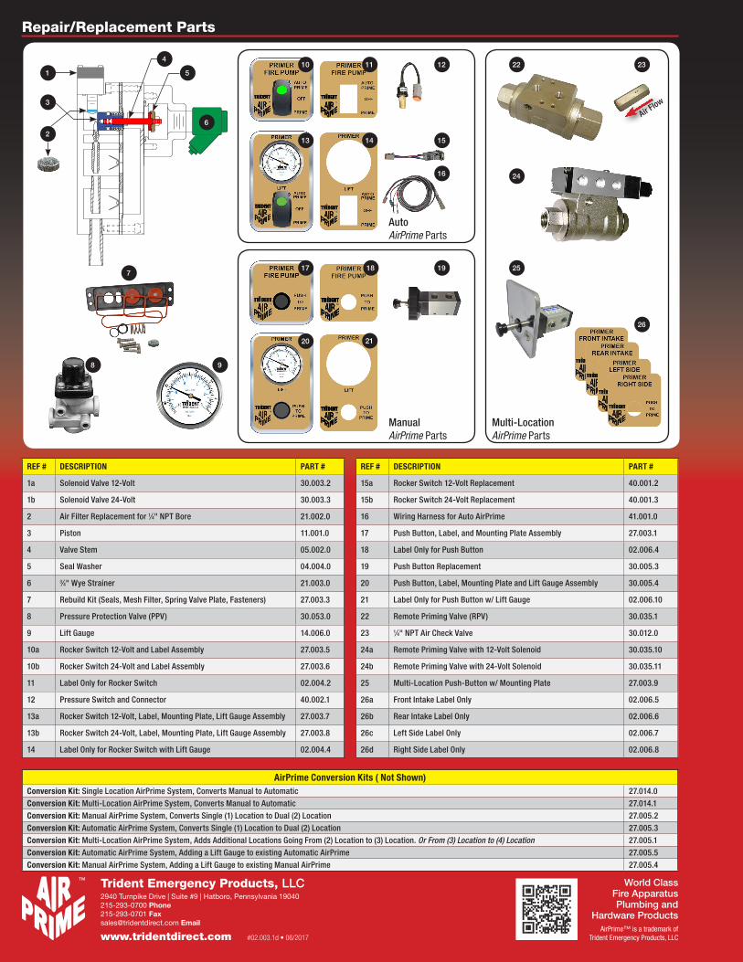
Repair/Replacement Parts
#02.003.1d • 06/2017
REF # DESCRIPTION PART #
1a Solenoid Valve 12-Volt 30.003.2
1b Solenoid Valve 24-Volt 30.003.3
2 Air Filter Replacement for 1⁄4" NPT Bore 21.002.0
3 Piston 11.001.0
4 Valve Stem 05.002.0
5 Seal Washer 04.004.0
6 3⁄4" Wye Strainer 21.003.0
7 Rebuild Kit (Seals, Mesh Filter, Spring Valve Plate, Fasteners) 27.003.3
8 Pressure Protection Valve (PPV) 30.053.0
9 Lift Gauge 14.006.0
10a Rocker Switch 12-Volt and Label Assembly 27.003.5
10b Rocker Switch 24-Volt and Label Assembly 27.003.6
11 Label Only for Rocker Switch 02.004.2
12 Pressure Switch and Connector 40.002.1
13a Rocker Switch 12-Volt, Label, Mounting Plate, Lift Gauge Assembly 27.003.7
13b Rocker Switch 24-Volt, Label, Mounting Plate, Lift Gauge Assembly 27.003.8
14 Label Only for Rocker Switch with Lift Gauge 02.004.4
REF # DESCRIPTION PART #
15a Rocker Switch 12-Volt Replacement 40.001.2
15b Rocker Switch 24-Volt Replacement 40.001.3
16 Wiring Harness for Auto AirPrime 41.001.0
17 Push Button, Label, and Mounting Plate Assembly 27.003.1
18 Label Only for Push Button 02.006.4
19 Push Button Replacement 30.005.3
20 Push Button, Label, Mounting Plate and Lift Gauge Assembly 30.005.4
21 Label Only for Push Button w/ Lift Gauge 02.006.10
22 Remote Priming Valve (RPV) 30.035.1
23 1⁄4" NPT Air Check Valve 30.012.0
24a Remote Priming Valve with 12-Volt Solenoid 30.035.10
24b Remote Priming Valve with 24-Volt Solenoid 30.035.11
25 Multi-Location Push-Button w/ Mounting Plate 27.003.9
26a Front Intake Label Only 02.006.5
26b Rear Intake Label Only 02.006.6
26c Left Side Label Only 02.006.7
26d Right Side Label Only 02.006.8
AirPrime Conversion Kits ( Not Shown)Conversion Kit: Single Location AirPrime System, Converts Manual to Automatic 27.014.0Conversion Kit: Multi-Location AirPrime System, Converts Manual to Automatic 27.014.1Conversion Kit: Manual AirPrime System, Converts Single (1) Location to Dual (2) Location 27.005.2Conversion Kit: Automatic AirPrime System, Converts Single (1) Location to Dual (2) Location 27.005.3Conversion Kit: Multi-Location AirPrime System, Adds Additional Locations Going From (2) Location to (3) Location. Or From (3) Location to (4) Location 27.005.1Conversion Kit: Automatic AirPrime System, Adding a Lift Gauge to existing Automatic AirPrime 27.005.5Conversion Kit: Manual AirPrime System, Adding a Lift Gauge to existing Manual AirPrime 27.005.4
26
6
7
8 9
12
15
16
19
22
24
25
1 5
4
6
2
10 11
13 14
17 18
20 21
AutoAirPrime Parts
Manual AirPrime Parts
Multi-LocationAirPrime Parts
Air Flow
23
3