Air Lift Kit 75619 - Aftermarket Auto Parts & · PDF filetroubleshooting of this Volkswagen...
61
For maximum effectiveness and safety, please read these instructions completely before proceeding with installation. Failure to read these instructions can result in an incorrect installation. MN-775 • (011110) • ERN 7180 INSTALLATION GUIDE Kit 75619 VW MKIV R32 Audi TT MKI Quattro rear application ™ Air Lift PERFORMANCE
Transcript of Air Lift Kit 75619 - Aftermarket Auto Parts & · PDF filetroubleshooting of this Volkswagen...
For maximum effectiveness and safety, please read these instructions completely before proceeding with installation.Failure to read these instructions can result in an incorrect installation.
MN
-775
• (
0111
10)
• E
RN
718
0 INSTALLATION GUIDE
Kit 75619VW MKIV R32Audi TT MKI Quattrorear application
™
Air LiftPERFORMANCE


1MN-775
Air Lift Performance
TABLE OF CONTENTS
1
Introduction . . . . . . . . . . . . . . . . . . . . . . . . . . . . . . . . . . . 2Notation Explanation . . . . . . . . . . . . . . . . . . . . . . . . . . . . . . . . . . . . . . . . . . . . . . . . 2Important Safety Notices . . . . . . . . . . . . . . . . . . . . . . . . . . . . . . . . . . . . . . . . . . . . 2
Installation Diagram . . . . . . . . . . . . . . . . . . . . . . . . . . . . 3Hardware List . . . . . . . . . . . . . . . . . . . . . . . . . . . . . . . . . . . . . . . . . . . . . . . . . . . . . 3Tools List . . . . . . . . . . . . . . . . . . . . . . . . . . . . . . . . . . . . . . . . . . . . . . . . . . . . . . . . . 3
Installing the Air Suspension. . . . . . . . . . . . . . . . . . . . . 4Preparing the vehicle . . . . . . . . . . . . . . . . . . . . . . . . . . . . . . . . . . . . . . . . . . . . . . . . 4Installing the air spring. . . . . . . . . . . . . . . . . . . . . . . . . . . . . . . . . . . . . . . . . . . . . . .10Tips for routing the air line . . . . . . . . . . . . . . . . . . . . . . . . . . . . . . . . . . . . . . . . . . . .14Aligning the vehicle . . . . . . . . . . . . . . . . . . . . . . . . . . . . . . . . . . . . . . . . . . . . . . . . .15
Before Operating . . . . . . . . . . . . . . . . . . . . . . . . . . . . . . . 16Installation Checklist . . . . . . . . . . . . . . . . . . . . . . . . . . . . . . . . . . . . . . . . . . . . . . . .17Post-installation checklist . . . . . . . . . . . . . . . . . . . . . . . . . . . . . . . . . . . . . . . . . . . .17
Product Use, Maintenance and Servicing. . . . . . . . . . . 18Suggested Driving Air Pressure and Maximum Air Pressure . . . . . . . . . . . . . . . . .18Maintenance Guidelines . . . . . . . . . . . . . . . . . . . . . . . . . . . . . . . . . . . . . . . . . . . . .18Troubleshooting Guide . . . . . . . . . . . . . . . . . . . . . . . . . . . . . . . . . . . . . . . . . . . . . .18Frequently Asked Questions . . . . . . . . . . . . . . . . . . . . . . . . . . . . . . . . . . . . . . . . . .18Tuning the Air Pressure . . . . . . . . . . . . . . . . . . . . . . . . . . . . . . . . . . . . . . . . . . . . . .19Checking for Leaks . . . . . . . . . . . . . . . . . . . . . . . . . . . . . . . . . . . . . . . . . . . . . . . . .19Fixing Leaks . . . . . . . . . . . . . . . . . . . . . . . . . . . . . . . . . . . . . . . . . . . . . . . . . . . . . .19
Warranty and Returns Policy . . . . . . . . . . . . . . . . . . . . . 20Replacement Information . . . . . . . . . . . . . . . . . . . . . . . . 20Contact Information . . . . . . . . . . . . . . . . . . . . . . . . . . . . 20
2 MN-775
Air Lift Performance
IntroductionThe purpose of this publication is to assist with the installation, maintenance and troubleshooting of this Volkswagen MKIV R32 and Audi TT MKI Quattro Performance kit.
It is important to read and understand the entire installation guide before beginning installation or performing any maintenance, service or repair. The information includes a hardware list, tool list, step-by-step installation information, maintenance tips, safety information and a troubleshooting guide.
Air Lift Company reserves the right to make changes and improvements to its products and publications at any time. For the latest version of this manual, contact Air Lift Company at (800) 248-0892 or visit our website at www.airliftcompany.com.
NOTATION EXPLANATIONHazard notations appear in various locations in this publication. Information which is highlighted by one of these notations must be observed to help minimize risk of personal injury or possible improper installation which may render the vehicle unsafe. Notes are used to help emphasize areas of procedural importance and provide helpful suggestions. The following definitions explain the use of these notations as they appear throughout this guide.
INDICATES IMMEDIATE HAZARDS WHICH WILL RESULT IN SEVERE PERSONAL INJURY OR DEATH.
INDICATES HAZARDS OR UNSAFE PRACTICES WHICH COULD RESULT IN SEVERE PERSONAL INJURY OR DEATH.
INDICATES HAZARDS OR UNSAFE PRACTICES WHICH COULD RESULT IN DAMAGE TO THE MACHINE OR MINOR PERSONAL INJURY.
Indicates a procedure, practice or hint which is important to highlight.
IMPORTANT SAFETY NOTICESThe installation of this kit does not alter the Gross Vehicle Weight Rating (GVWR) or payload of the vehicle. Check your vehicleʼs ownerʼs manual and do not exceed the maximum load listed for your vehicle.
Gross Vehicle Weight Rating: The maximum allowable weight of the fully loaded vehicle (including passengers and cargo). This number — along with other weight limits, as well as tire, rim size and inflation pressure data — is shown on the vehicle’s Safety Compliance Certification Label.
Payload: The combined, maximum allowable weight of cargo and passengers that the vehicle is designed to carry. Payload is GVWR minus the Base Curb Weight.
DO NOT INFLATE AIR SPRINGS WHILE OFF OF THE VEHICLE. DAMAGE TO ASSEMBLY MAY RESULT AND VOID WARRANTY.
DO NOT WELD TO, OR MODIFY LIFESTYLE STRUTS/SHOCKS IN ANY WAY. DAMAGE TO UNIT MAY OCCUR AND WILL VOID WARRANTY.
DANGER
NOTE
WARNING
CAUTION
WARNING
CAUTION

3MN-775
Air Lift Performance
Installation Diagram
TOOLS LIST
DescriptionJackJack stands or hoistStepped drill bitDrillMetal cutting sawMetric wrenchesTorque wrench
Item Part # Description ............................... Qty A 58527 Air spring.............................................2 B 11928 Roll plate .............................................2 C 21745 Connector, 1/4” MNPT x 1/4” PTC......2 D 21853 Connector, 1/4 MNPT x 3/8” PTC .......2
HARDWARE LIST
Missing or damaged parts? Call Air Lift customer service at (800) 248-0892 for a replacement part.
STOP!
fig. 1
C or D
A
B
4 MN-775
Air Lift Performance
PREPARING THE VEHICLE
1. Elevate the vehicle and support the body with a hoist or jack stands. Trailing link must be free to move.
2. Remove the rear wheels.
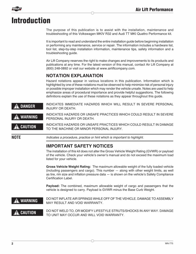
If the vehicle is equipped with Auto-Leveling Headlight Control, detach the linkage from the lower control arm to prevent overextension (fig. 2).
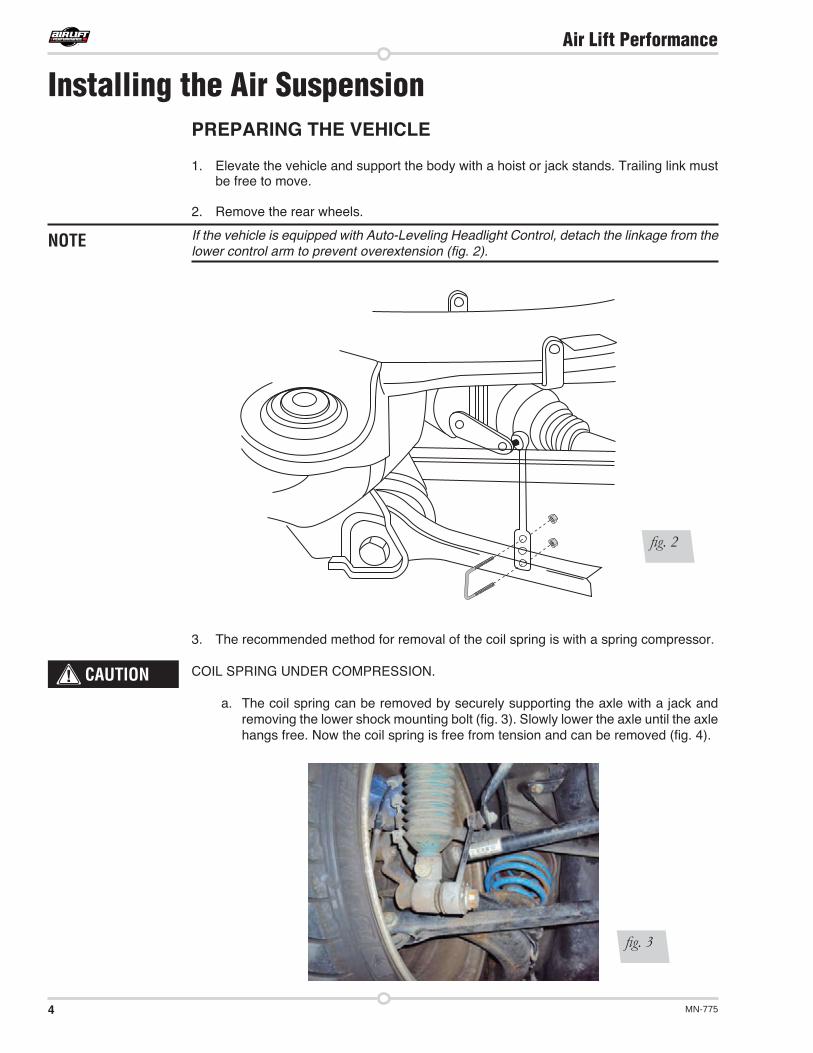
3. The recommended method for removal of the coil spring is with a spring compressor.
COIL SPRING UNDER COMPRESSION.
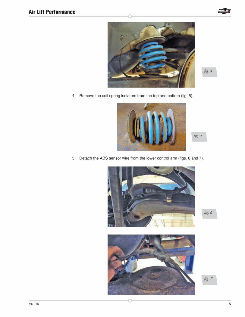
a. The coil spring can be removed by securely supporting the axle with a jack and removing the lower shock mounting bolt (fig. 3). Slowly lower the axle until the axle hangs free. Now the coil spring is free from tension and can be removed (fig. 4).
Installing the Air Suspension
fig. 3
NOTE
CAUTION
fig. 2
5MN-775
Air Lift Performance
4. Remove the coil spring isolators from the top and bottom (fig. 5).
5. Detach the ABS sensor wire from the lower control arm (figs. 6 and 7).
fig. 4
fig. 6
fig. 5
fig. 7
6 MN-775
Air Lift Performance
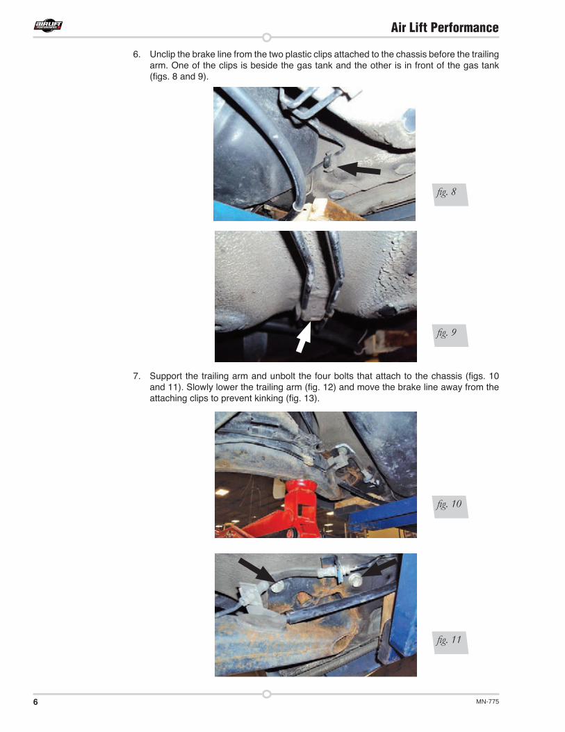
6. Unclip the brake line from the two plastic clips attached to the chassis before the trailing arm. One of the clips is beside the gas tank and the other is in front of the gas tank (figs. 8 and 9).
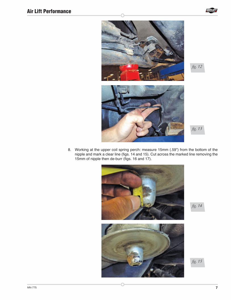
7. Support the trailing arm and unbolt the four bolts that attach to the chassis (figs. 10 and 11). Slowly lower the trailing arm (fig. 12) and move the brake line away from the attaching clips to prevent kinking (fig. 13).
fig. 10
fig. 8
fig. 9
fig. 11
7MN-775
Air Lift Performance
8. Working at the upper coil spring perch: measure 15mm (.59”) from the bottom of the nipple and mark a clear line (figs. 14 and 15). Cut across the marked line removing the 15mm of nipple then de-burr (figs. 16 and 17).
fig. 12
fig. 13
fig. 14
fig. 15

8 MN-775
Air Lift Performance
9. Center punch and drill a pilot hole through the center of the nipple (figs. 18, 19 and 20).
fig. 16
fig. 17
fig. 18
fig. 19

9MN-775
Air Lift Performance
10. Using a stepped drill bit, drill large access holes for the air line to run through (fig. 21). Make certain the hole is large enough to allow the air line to radius around into the chassis channel without kinking or abrading the air line (fig. 22).
11. Place the recessed portion of the air spring over the spring perch nipple and verify the air spring will seat flush with the spring perch flats.
fig. 20
fig. 21
fig. 22
10 MN-775
Air Lift Performance
INSTALLING THE AIR SPRING
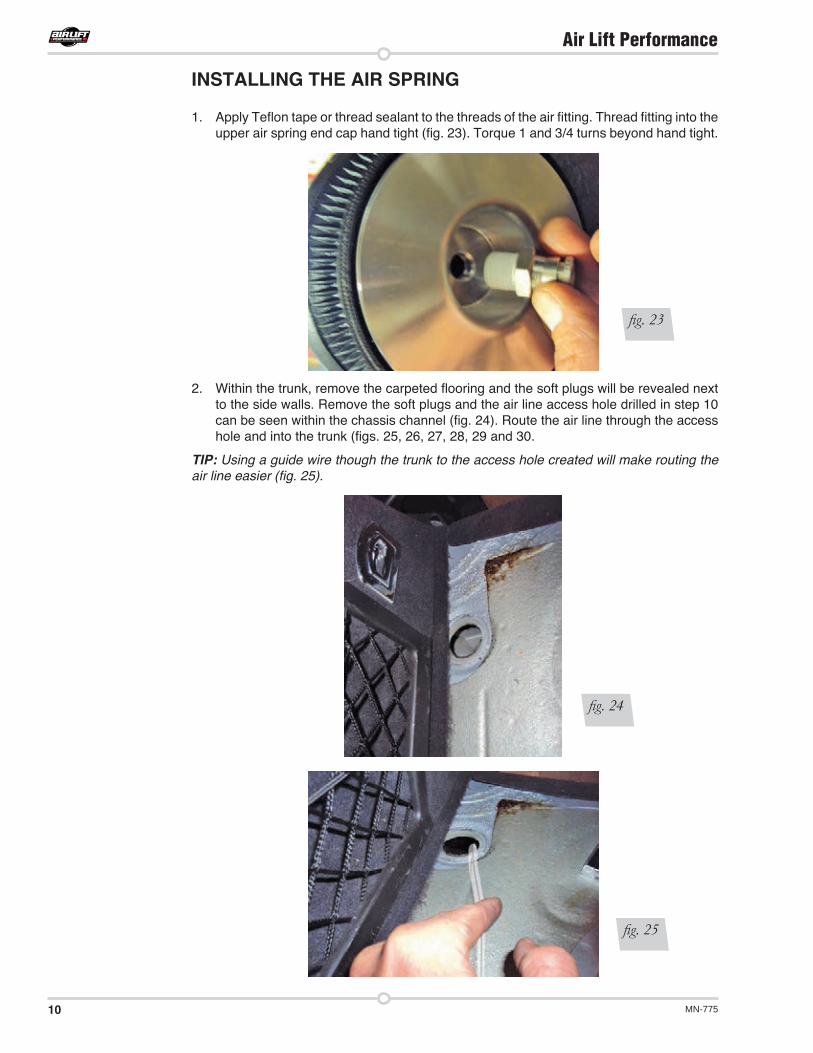
1. Apply Teflon tape or thread sealant to the threads of the air fitting. Thread fitting into the upper air spring end cap hand tight (fig. 23). Torque 1 and 3/4 turns beyond hand tight.
2. Within the trunk, remove the carpeted flooring and the soft plugs will be revealed next to the side walls. Remove the soft plugs and the air line access hole drilled in step 10 can be seen within the chassis channel (fig. 24). Route the air line through the access hole and into the trunk (figs. 25, 26, 27, 28, 29 and 30.
TIP: Using a guide wire though the trunk to the access hole created will make routing the air line easier (fig. 25).
fig. 23
fig. 24
fig. 25

11MN-775
Air Lift Performance
fig. 26
fig. 27
fig. 28
fig. 29

12 MN-775
Air Lift Performance
3. Lift the trailing arm and reattach the four previously removed bolts that attach the trailing link to the chassis (figs. 31 and 32). Reattach the brake lines and ABS sensor wire (figs. 33, 34 and 35).
fig. 30
fig. 31
fig. 32
fig. 33

13MN-775
Air Lift Performance
4. Insert the air supply line into the air fitting (fig. 36). Collapse the air spring and nest the air spring upper end cap around the upper coil spring perch (fig. 37). Locate the air spring lower end cap pin into the trailing link hole (fig. 37).
fig. 34
fig. 35
fig. 36
fig. 37
14 MN-775
Air Lift Performance
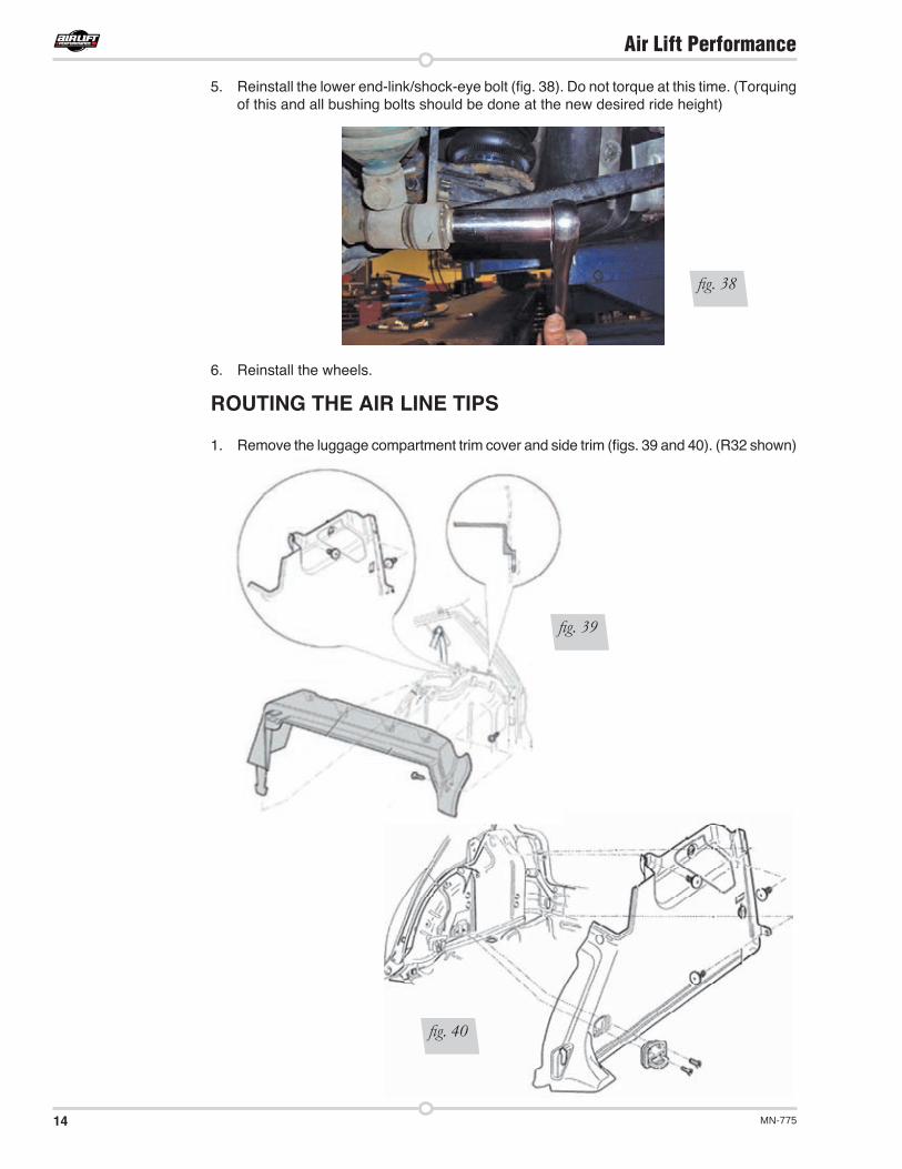
5. Reinstall the lower end-link/shock-eye bolt (fig. 38). Do not torque at this time. (Torquing of this and all bushing bolts should be done at the new desired ride height)
6. Reinstall the wheels.
ROUTING THE AIR LINE TIPS
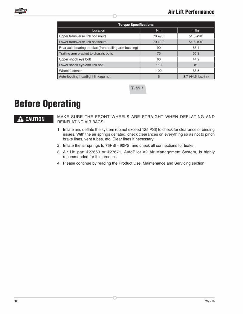
1. Remove the luggage compartment trim cover and side trim (figs. 39 and 40). (R32 shown)
fig. 38
fig. 39
fig. 40

15MN-775
Air Lift Performance
2. Two options for routing (figs. 41 and 42):
a. Drill a ½” or larger hole against the wheel housing. Cut a straight line from the soft plug hole over to the newly drilled hole. Fold the metal between the two holes along the cut line. Slide the air line over to the new hole against the wheel housing. Fold the metal back down flat. Apply grommet material around the hole. Reinstall the soft plug.
B. Grind material away from the soft plug hole to the wheel housing. Apply grommet material around the sharp edges. Move the air line over to the wheel housing and reinstall the soft plug.
3. Decide where the control system will be located and route the remaining air line accordingly.
4. With the air line against the wheel housing, reinstall the luggage compartment trim.
5. Voila! Rejoice in a job well done!!
ALIGNING THE VEHICLE
1. Using the control system, set the vehicle height to the new custom ride height.
2. If the custom ride height is lower than stock, we recommend loosening all pivot points (bolts, nuts) on any control arm, strut arm or radius rod that contains bushings. Once they have been loosened, re-torque to stock specifications.
It may be necessary to cycle the suspension to loosen the bushing up from its mount. This will help unload the bushing to make it last longer at its new position based on the custom ride height.
fig. 41
fig. 42
NOTE
16 MN-775
Air Lift Performance
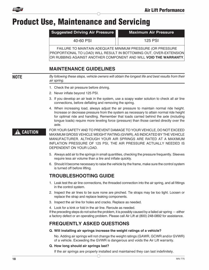
Table 1
Torque Specifications
Location Nm ft. lbs.Upper transverse link bolts/nuts 70 +90˚ 51.6 +90˚
Lower transverse link bolts/nuts 70 +90˚ 51.6 +90˚
Rear axle bearing bracket (front trailing arm bushing) 90 66.4
Trailing arm bracket to chassis bolts 75 55.3Upper shock eye bolt 60 44.2Lower shock eye/end link bolt 110 81
Wheel fastener 120 88.5
Auto-leveling headlight linkage nut 5 3.7 (44.5 lbs.-in.)
MAKE SURE THE FRONT WHEELS ARE STRAIGHT WHEN DEFLATING AND REINFLATING AIR BAGS.
1. Inflate and deflate the system (do not exceed 125 PSI) to check for clearance or binding issues. With the air springs deflated, check clearances on everything so as not to pinch brake lines, vent tubes, etc. Clear lines if necessary.
2. Inflate the air springs to 75PSI - 90PSI and check all connections for leaks.
3. Air Lift part #27669 or #27671, AutoPilot V2 Air Management System, is highly recommended for this product.
4. Please continue by reading the Product Use, Maintenance and Servicing section.
Before OperatingCAUTION
17MN-775
Air Lift Performance
Technicianʼs Signature _________________________________
Date_________________
Clearance test — Inflate the air springs to 75-90 PSI and make sure there is at least ½” clearance from anything that might rub against each sleeve. Be sure to check the tire, brake drum, frame, shock absorbers and brake cables.
Leak test before road test — Inflate the air springs to 75PSI - 90PSI and check all connections for leaks. All leaks must be eliminated before the vehicle is road tested.
Heat test — Be sure there is sufficient clearance from heat sources, at least 6” for air springs and air lines. If a heat shield was included in the kit, install it. If there is no heat shield, but one is required, call Air Lift customer service at (800) 248-0892.
Fastener test — Recheck all bolts for proper torque.
Road test — The vehicle should be road tested after the preceding tests. Inflate the springs to recommended driving pressures. Drive the vehicle 10 miles and recheck for clearance, loose fasteners and air leaks.
Operating instructions — If professionally installed, the installer should review the operating instructions with the owner. Be sure to provide the owner with all of the paperwork that came with the kit.
INSTALLATION CHECKLIST
Overnight leak down test — Recheck air pressure after the vehicle has been used for 24 hours. If the pressure has dropped more than 5 PSI, then there is a leak that must be fixed. Either fix the leak yourself or return to the installer for service.
Air pressure requirements — I understand the air pressure requirements of my air spring system. Regardless of load, the air pressure should always be adjusted to maintain adequate ride height at all times while driving.
Thirty day or 500 mile test — I understand that I must recheck the air spring system after 30 days or 500 miles, whichever comes first. If any part shows signs of rubbing or abrasion, the source should be identified and moved, if possible. If it is not possible to relocate the cause of the abrasion, the air spring may need to be remounted. If professionally installed, the installer should be consulted. Check all fasteners for tightness.
POST-INSTALLATION CHECKLIST
18 MN-775
Air Lift Performance
MAINTENANCE GUIDELINESBy following these steps, vehicle owners will obtain the longest life and best results from their air spring.
1. Check the air pressure before driving.
2. Never inflate beyond 125 PSI.
3. If you develop an air leak in the system, use a soapy water solution to check all air line connections, before deflating and removing the spring.
4. When increasing load, always adjust the air pressure to maintain normal ride height. Increase or decrease pressure from the system as necessary to attain normal ride height for optimal ride and handling. Remember that loads carried behind the axle (including tongue loads) require more leveling force (pressure) than those carried directly over the axle.
FOR YOUR SAFETY AND TO PREVENT DAMAGE TO YOUR VEHICLE, DO NOT EXCEED MAXIMUM GROSS VEHICLE WEIGHT RATING (GVWR), AS INDICATED BY THE VEHICLE MANUFACTURER. ALTHOUGH YOUR AIR SPRINGS ARE RATED AT A MAXIMUM INFLATION PRESSURE OF 125 PSI, THE AIR PRESSURE ACTUALLY NEEDED IS DEPENDENT ON YOUR LOAD.
5. Always add air to the springs in small quantities, checking the pressure frequently. Sleeves require less air volume than a tire and inflate quickly.
6. Should it become necessary to raise the vehicle by the frame, make sure the control system is turned off before lifting.
TROUBLESHOOTING GUIDE1. Leak test the air line connections, the threaded connection into the air spring, and all fittings
in the control system. 2. Inspect the air lines to be sure none are pinched. Tie straps may be too tight. Loosen or
replace the strap and replace leaking components.3. Inspect the air line for holes and cracks. Replace as needed.
4. Look for a kink or fold in the air line. Reroute as needed.If the preceding steps do not solve the problem, it is possibly caused by a failed air spring — either a factory defect or an operating problem. Please call Air Lift at (800) 248-0892 for assistance.
FREQUENTLY ASKED QUESTIONSQ. Will installing air springs increase the weight ratings of a vehicle?
No. Adding air springs will not change the weight ratings (GAWR, GCWR and/or GVWR) of a vehicle. Exceeding the GVWR is dangerous and voids the Air Lift warranty.
Q. How long should air springs last?If the air springs are properly installed and maintained they can last indefinitely.
NOTE
CAUTION
Product Use, Maintenance and Servicing
40-60 PSI 125 PSI
FAILURE TO MAINTAIN ADEQUATE MINIMUM PRESSURE (OR PRESSURE PROPORTIONAL TO LOAD) WILL RESULT IN BOTTOMING OUT, OVER-EXTENSION OR RUBBING AGAINST ANOTHER COMPONENT AND WILL VOID THE WARRANTY.
Maximum Air PressureSuggested Driving Air Pressure
19MN-775
Air Lift Performance
Q. Will raising the vehicle on a hoist for service work damage the air springs?No. The vehicle can be lifted on a hoist for short-term service work such as tire rotation or oil changes. However, if the vehicle will be on the hoist for a prolonged period of time, support the axle with jack stands in order to take the tension off of the air springs.
TUNING THE AIR PRESSUREPressure determination comes down to three things — level vehicle, ride comfort, and stability.1. Level vehicle
If the vehicleʼs headlights are shining into the trees or the vehicle is leaning to one side, then it is not level. Raise the air pressure to correct either of these problems and level the vehicle.
2. Ride comfortIf the vehicle has a rough or harsh ride it may be due to either too much pressure or not enough. Try different pressures to determine the best ride comfort. See Air Lift suggested driving air pressure.
3. StabilityStability translates into safety and should be the priority, meaning the driver may need to sacrifice a perfectly level and comfortable ride. Stability issues include roll control, bounce, dive during braking and sponginess. Tuning out these problems usually requires additional air pressure, strut damping, or both.
CHECKING FOR LEAKS1. Inflate the air spring to 80 PSI.
2. Spray all connections and the inflation valves with a solution of 1/5 liquid dish soap and 4/5 water. Spot leaks easily by looking for bubbles in the soapy water.
3. After the test, deflate the springs to the minimum pressure required to restore the system to normal ride height.
4. Check the air pressure again after 24 hours. A 2 - 4 PSI loss after initial installation is normal. Retest for leaks if the loss is more than 5 lbs.
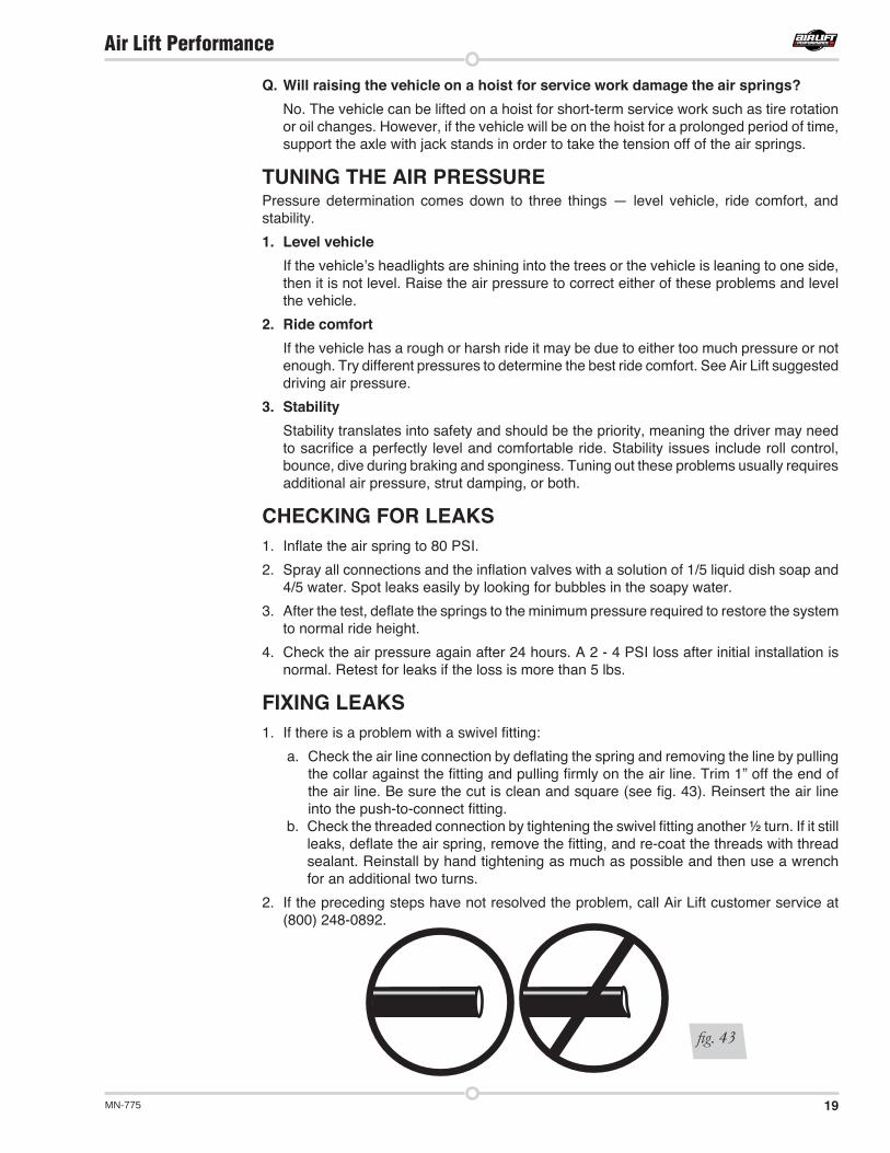
FIXING LEAKS1. If there is a problem with a swivel fitting:
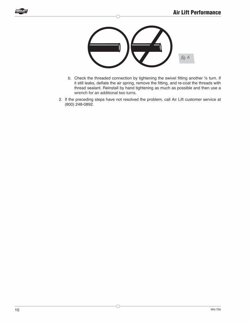
a. Check the air line connection by deflating the spring and removing the line by pulling the collar against the fitting and pulling firmly on the air line. Trim 1” off the end of the air line. Be sure the cut is clean and square (see fig. 43). Reinsert the air line into the push-to-connect fitting.
b. Check the threaded connection by tightening the swivel fitting another ½ turn. If it still leaks, deflate the air spring, remove the fitting, and re-coat the threads with thread sealant. Reinstall by hand tightening as much as possible and then use a wrench for an additional two turns.
2. If the preceding steps have not resolved the problem, call Air Lift customer service at (800) 248-0892.
fig. 43
20 MN-775
Air Lift Performance
Contact InformationIf you have any questions, comments or need technical assistance contact our customer service department by calling (800) 248-0892, Monday through Friday, 8 a.m. to 7 p.m. Eastern Time. For calls from outside the USA or Canada, our local number is (517) 322-2144. You may also contact customer service anytime by e-mail at [email protected] inquiries by mail, our address is PO Box 80167, Lansing, MI 48908-0167. Our shipping address for returns is 2727 Snow Road, Lansing, MI 48917. You may also contact our sales team anytime by e-mail at [email protected] or on the web at www.airliftperformance.com.
Replacement InformationIf you need replacement parts, contact the local dealer or call Air Lift customer service at (800) 248-0892. Most parts are immediately available and can be shipped the same day.
Contact Air Lift Company customer service at (800) 248-0892 first if:
Air Lift Company warrants its performance products for one year to the original purchaser against manufacturing defects one year from the date of purchase when used on cars and trucks as specified under normal operating conditions. The warranty does not apply to products that have been improperly applied, improperly installed, or which have not been maintained in accordance with installation instructions furnished with all products. The consumer will be responsible for removing (labor charges) the defective product from the vehicle and returning it, transportation costs prepaid, to the dealer from which it was purchased or to Air Lift Company for verification. Air Lift will repair or replace, at its option, defective products or components. A minimum $10.00 shipping and handling charge will apply to all warranty claims. Before returning any defective product, you must call Air Lift at (800) 248-0892 in the U.S. and Canada (elsewhere, (517) 322-2144) for a Returned Materials Authorization (RMA) number. Returns to Air Lift can be sent to: Air Lift Company • 2727 Snow Road • Lansing, MI • 48917. Product failures resulting from abnormal use or misuse are excluded from this warranty. The loss of use of the product, loss of time, inconvenience, commercial loss or consequential damages is not covered. The consumer is responsible for installation/reinstallation (labor charges) of the product. Air Lift Company reserves the right to change the design of any product without assuming any obligation to modify any product previously manufactured. This warranty gives you specific legal rights and you may also have other rights that may vary from state-to-state. Some states do not allow limitations on how long an implied warranty lasts or allow the exclusion or limitation of incidental or consequential damages. The above limitation or exclusion may not apply to you. There are no warranties, expressed or implied including any implied warranties of merchantability and fitness, which extend beyond this warranty period. There are no warranties that extend beyond the description on the face hereof. Seller disclaims the implied warranty of merchantability. (Dated proof of purchase required.)
Warranty and Returns Policy
• Parts are missing from the kit.• Need technical assistance on installation or
operation.
• Broken or defective parts in the kit.• Wrong parts in the kit.• Have a warranty claim or question.
Contact the retailer where the kit was purchased:• If it is necessary to return or exchange the kit for any reason.• If there is a problem with shipping if shipped from the retailer.• If there is a problem with the price.

21MN-775
Air Lift Performance
NOTES

Air Lift Company • 2727 Snow Road • Lansing, MI 48917 or PO Box 80167 • Lansing, MI 48908-0167 Toll Free (800) 248-0892 • Local (517) 322-2144 • Fax (517) 322-0240 • www.airliftperformance.com
Thank you for purchasing Air Lift Performance products!
Printed in the USA
Need Help?Contact our customer service department by calling (800) 248-0892, Monday through Friday, 8 a.m. to 7 p.m. Eastern Time. For calls from outside the USA or Canada, our local number is (517) 322-2144.

For maximum effectiveness and safety, please read these instructions completely before proceeding with installation.
Failure to read these instructions can result in an incorrect installation.
MN
-756
• (
0211
11)
• E
CR
718
9 INSTALLATION GUIDE
Kit 75518MK IV PlatformSlam front application
NOTE: FOR USE ON VEHICLES W I T H F R A M E C - N O T C H M O D I F I C A T I O N S O N L Y . FRONT SWAY BAR MUST BE REMOVED.
™
Air LiftPERFORMANCE

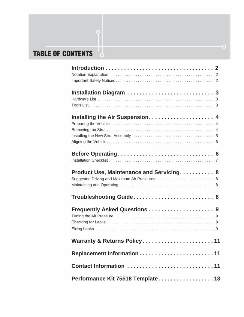
TABLE OF CONTENTS
Introduction . . . . . . . . . . . . . . . . . . . . . . . . . . . . . . . . . . . 2Notation Explanation . . . . . . . . . . . . . . . . . . . . . . . . . . . . . . . . . . . . . . . . . . . . . . . 2Important Safety Notices . . . . . . . . . . . . . . . . . . . . . . . . . . . . . . . . . . . . . . . . . . . . . 2
Installation Diagram . . . . . . . . . . . . . . . . . . . . . . . . . . . . 3Hardware List . . . . . . . . . . . . . . . . . . . . . . . . . . . . . . . . . . . . . . . . . . . . . . . . . . . . . 3Tools List . . . . . . . . . . . . . . . . . . . . . . . . . . . . . . . . . . . . . . . . . . . . . . . . . . . . . . . . . 3
Installing the Air Suspension . . . . . . . . . . . . . . . . . . . . . 4Preparing the Vehicle . . . . . . . . . . . . . . . . . . . . . . . . . . . . . . . . . . . . . . . . . . . . . . . 4Removing the Strut . . . . . . . . . . . . . . . . . . . . . . . . . . . . . . . . . . . . . . . . . . . . . . . . . 4Installing the New Strut Assembly . . . . . . . . . . . . . . . . . . . . . . . . . . . . . . . . . . . . . . 5Aligning the Vehicle . . . . . . . . . . . . . . . . . . . . . . . . . . . . . . . . . . . . . . . . . . . . . . . . . 6
Before Operating . . . . . . . . . . . . . . . . . . . . . . . . . . . . . . . 6Installation Checklist . . . . . . . . . . . . . . . . . . . . . . . . . . . . . . . . . . . . . . . . . . . . . . . . 7
Product Use, Maintenance and Servicing . . . . . . . . . . . 8Suggested Driving and Maximum Air Pressures . . . . . . . . . . . . . . . . . . . . . . . . . . . 8Maintaining and Operating . . . . . . . . . . . . . . . . . . . . . . . . . . . . . . . . . . . . . . . . . . . 8
Troubleshooting Guide . . . . . . . . . . . . . . . . . . . . . . . . . . 8
Frequently Asked Questions . . . . . . . . . . . . . . . . . . . . . 9Tuning the Air Pressure . . . . . . . . . . . . . . . . . . . . . . . . . . . . . . . . . . . . . . . . . . . . . 9Checking for Leaks . . . . . . . . . . . . . . . . . . . . . . . . . . . . . . . . . . . . . . . . . . . . . . . . . 9
Fixing Leaks . . . . . . . . . . . . . . . . . . . . . . . . . . . . . . . . . . . . . . . . . . . . . . . . . . . . . . 9
Warranty & Returns Policy . . . . . . . . . . . . . . . . . . . . . . . 11
Replacement Information . . . . . . . . . . . . . . . . . . . . . . . . 11
Contact Information . . . . . . . . . . . . . . . . . . . . . . . . . . . . 11
Performance Kit 75518 Template . . . . . . . . . . . . . . . . . . 13

MN-756
IntroductionThe purpose of this publication is to assist with the installation, maintenance and troubleshooting of this MKIV Performance Slam kit.
It is important to read and understand the entire installation guide before beginning installation or performing any maintenance, service or repair. The information includes a hardware list, tool list, step-by-step installation information, maintenance tips, safety information and a troubleshooting guide.
Air Lift Company reserves the right to make changes and improvements to its products and publications at any time. For the latest version of this manual, contact Air Lift Company at (800) 248-0892 or visit our website at www.airliftcompany.com.
NOTATION EXPLANATIONHazard notations appear in various locations in this publication. Information which is highlighted by one of these notations must be observed to help minimize risk of personal injury or possible improper installation which may render the vehicle unsafe. Notes are used to help emphasize areas of procedural importance and provide helpful suggestions. The following definitions explain the use of these notations as they appear throughout this guide.
INDICATES IMMEDIATE HAZARDS WHICH WILL RESULT IN SEVERE PERSONAL INJURY OR DEATH.
INDICATES HAZARDS OR UNSAFE PRACTICES WHICH COULD RESULT IN SEVERE PERSONAL INJURY OR DEATH.
INDICATES HAZARDS OR UNSAFE PRACTICES WHICH COULD RESULT IN DAMAGE TO THE MACHINE OR MINOR PERSONAL INJURY.
Indicates a procedure, practice or hint which is important to highlight.
IMPORTANT SAFETY NOTICESThe installation of this kit does not alter the Gross Vehicle Weight Rating (GVWR) or payload of the vehicle. Check your vehicle’s owner’s manual and do not exceed the maximum load listed for your vehicle.
Gross Vehicle Weight Rating: The maximum allowable weight of the fully loaded vehicle (including passengers and cargo). This number — along with other weight limits, as well as tire, rim size and inflation pressure data — is shown on the vehicle’s Safety Compliance Certification Label.
Payload: The combined, maximum allowable weight of cargo and passengers that the vehicle is designed to carry. Payload is GVWR minus the Base Curb Weight.
DO NOT INFLATE AIR SPRINGS WHILE OFF OF THE VEHICLE. DAMAGE TO ASSEMBLY MAY RESULT AND VOID WARRANTY.
DO NOT WELD TO, OR MODIFY LIFESTYLE STRUTS/SHOCKS IN ANY WAY. DAMAGE TO UNIT MAY OCCUR AND WILL VOID WARRANTY.
DANGER
NOTE
WARNING
CAUTION
WARNING
CAUTION
Air Lift Performance
2
MN-756
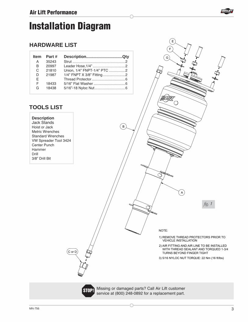
Installation Diagram
fig. 1
Missing or damaged parts Call Air Lift customer service at (800) 248-0892 for a replacement part.
STOP!
TOOLS LIST
DescriptionJack StandsHoist or JackMetric WrenchesStandard WrenchesVW Spreader Tool 3424Center PunchHammerDrill3/8” Drill Bit
NOTE:
1) REMOVE THREAD PROTECTORS PRIOR TO VEHICLE INSTALLATION
2) AIR FITTING AND AIR LINE TO BE INSTALLED WITH THREAD SEALANT AND TORQUED 1-3/4 TURNS BEYOND FINGER TIGHT
3) 5/16 NYLOC NUT TORQUE: 22 Nm (16 ft/lbs)
C or D
B
A
G
F
EHARDWARE LIST
Item Part # Description................................QtyA 35243 Strut ....................................................2
B 20997 Leader Hose,1/4” ................................2 C 21810 Union, 1/4” FNPT-1/4” PTC ................2 D 21987 1/4” FNPT X 3/8” Fitting ......................2 E Thread Protector .................................6 F 18433 5/16” Flat Washer ...............................6 G 18438 5/16”-18 Nyloc Nut ..............................6
Air Lift Performance
3

MN-756
Installing the Air SuspensionPREPARING THE VEHICLE1. Elevate the vehicle and support the body with a hoist or jack stands.
2. Remove the front wheels.
REMOVING THE STRUT1. Unbolt the two mounting bolts for the brake caliper and secure or hang the caliper to the
body of the vehicle. Fig 2
fig. 2
DO NOT ALLOW CALIPER TO HANG FROM THE BRAKE LINE OR DAMAGE MAY OCCUR.
2. Unclip the speed sensor wiring from the strut.
3. Remove the three lower bolts from the lower ball joint and control arm. Detach the ball joint and hub assembly from the control arm. Fig 2
4. To remove the left and right front strut, mark the installed orientation and disconnect the axle from the transmission drive flange.
TO PREVENT DAMAGE TO THE AXLE JOINT, DO NOT ALLOW THE AXLE TO HANG FREE
5. Remove the bolt at the back of the hub assembly to the strut.
6. Spread the hub assembly slot and push down on the hub to release the strut from its lower mount. (fig. 3 - Volkswagen specific tool is spreader 3424)
CAUTION
CAUTION
Air Lift Performance
4

MN-756
7. Remove the upper mount nut and remove strut from vehicle.
8. Reattach the lower control arm to the ball joint and torque bolts to 20 Nm (15 ft. lbs.) + 90.
9. Reinstall the axle shaft to the transmission drive flange in the previously installed orientation. Torque bolts to
M8 x 18: 20 Nm (15 ft. lbs.) + 90
M8 x 28: 20 Nm (15 ft. lbs.) + 90
M8 x 48: 20 Nm (15 ft. lbs.) + 90
M10 x 23: 50 Nm (37 ft. lbs.) + 45
M10 x 52: 50 Nm (37 ft. lbs.) + 45
fig. 3
3424
2. Using the supplied template and working from inside the strut pocket, center the template and orient so that there is clearance for the washers on top. Once the template is centered, secure in place with tape. Use a center punch and hammer on the center lines of the template to mark into the drilling surface. Remove the template and drill 3/8” holes through the strut pocket. Insert the strut upper mounting bracket through the holes. If it does not fit, adjust the holes accordingly. Do not attach the strut to the vehicle body yet.
fig. 4
INSTALLING THE NEW STRUT ASSEMBLY2. Install braided hose (B) into the lower end-cap of the airspring with thread sealant or
Teflon tape applied to the threads of the fitting. Tighten finger tight and torque fitting 1-3/4 turns beyond hand tight. Attach the fitting (C or D) to the braided line with thread sealant (fig. 4).
Air Lift Performance
5

MN-756
1. Some vehicles come with a nine-position damping dial for added adjustability (fig. 5). If not, proceed to 2.
Before driving your vehicle, set the new struts to their highest setting by turning the black dial on the shaft of the strut as far as it will go to the right (position 9).
2. Next, completely deflate and reinflate the air bags 2-3 times. This procedure will purge any trapped air in the dampers and allow for maximum performance. For ride performance and the most versatility, Lifestyle recommends setting the strut dial (if equipped) to position 6 or higher.
MAKE SURE THE FRONT WHEELS ARE STRAIGHT WHEN DEFLATING AND REINFLATING AIR BAGS.
3. Inflate and deflate the system (do not exceed 125 PSI) to check for clearance or binding issues. With the air springs deflated, check clearances on everything so as not to pinch brake lines, vent tubes, etc. Clear lines if necessary.
4. Inflate the air springs to 75PSI - 90PSI and check all connections for leaks.
5. Air Lift part #27669 or #27671, AutoPilot V2 Air Management System, is highly recommended for this product.
6. Please continue by reading the Product Use, Maintenance and Servicing section.
fig. 5
Increase damping(stiffer ride)
Decrease damping(softer ride)
Before Operating
CAUTION
3. Insert strut into the hub assembly. Reinstall the lower mounting bolt and torque to 70 Nm (52 ft. lbs.) +90 .
4. Lift assembly into strut pocket and align upper mounting bolts with three holes. Using the supplied nuts and washers, tighten the upper mount to 22 NM (16 ft lbs).
5. Reinstall the brake caliper and torque to 28Nm (21 ft/lbs).
6. Attach the speed sensor wiring to the new strut assembly.
Air Lift Performance
6

MN-756
Technician’s Signature _________________________________
Date_________________
Clearance test — Inflate the air springs to 75-90 PSI and make sure there is at least ½” clearance from anything that might rub against each sleeve. Be sure to check the tire, brake drum, frame, shock absorbers and brake cables.
Leak test before road test — Inflate the air springs to 75PSI - 90PSI and check all connections for leaks. All leaks must be eliminated before the vehicle is road tested.
Heat test — Be sure there is sufficient clearance from heat sources, at least 6” for air springs and air lines. If a heat shield was included in the kit, install it. If there is no heat shield, but one is required, call Air Lift customer service at (800) 248-0892.
Fastener test — Recheck all bolts for proper torque.
Road test — The vehicle should be road tested after the preceding tests. Inflate the springs to recommended driving pressures. Drive the vehicle 10 miles and recheck for clearance, loose fasteners and air leaks.
Operating instructions — If professionally installed, the installer should review the operating instructions with the owner. Be sure to provide the owner with all of the paperwork that came with the kit.
INSTALLATION CHECKLIST
Overnight leak down test — Recheck air pressure after the vehicle has been used for 24 hours. If the pressure has dropped more than 5 PSI, then there is a leak that must be fixed. Either fix the leak yourself or return to the installer for service.
Air pressure requirements — I understand the air pressure requirements of my air spring system. Regardless of load, the air pressure should always be adjusted to maintain adequate ride height at all times while driving.
Thirty day or 500 mile test — I understand that I must recheck the air spring system after 30 days or 500 miles, whichever comes first. If any part shows signs of rubbing or abrasion, the source should be identified and moved, if possible. If it is not possible to relocate the cause of the abrasion, the air spring may need to be remounted. If professionally installed, the installer should be consulted. Check all fasteners for tightness.
POST-INSTALLATION CHECKLIST
Air Lift Performance
7

MN-756
MAINTENANCE GUIDELINESBy following these steps, vehicle owners will obtain the longest life and best results from their air spring.
1. Check the air pressure before driving.
2. Never inflate beyond 125 PSI.
3. If you develop an air leak in the system, use a soapy water solution to check all air line connections, before deflating and removing the spring.
4. When increasing load, always adjust the air pressure to maintain normal ride height. Increase or decrease pressure from the system as necessary to attain normal ride height for optimal ride and handling. Remember that loads carried behind the axle (including tongue loads) require more leveling force (pressure) than those carried directly over the axle.
FOR YOUR SAFETY AND TO PREVENT DAMAGE TO YOUR VEHICLE, DO NOT EXCEED MAXIMUM GROSS VEHICLE WEIGHT RATING (GVWR), AS INDICATED BY THE VEHICLE MANUFACTURER. ALTHOUGH YOUR AIR SPRINGS ARE RATED AT A MAXIMUM INFLATION PRESSURE OF 125 PSI, THE AIR PRESSURE ACTUALLY NEEDED IS DEPENDENT ON YOUR LOAD.
5. Always add air to the springs in small quantities, checking the pressure frequently. Sleeves require less air volume than a tire and inflate quickly.
6. Should it become necessary to raise the vehicle by the frame, make sure the control system is turned off before lifting.
NOTE
CAUTION
Troubleshooting Guide1. Leak test the air line connections, threaded connection of the elbow into the air spring, and
the inflation valves.
2. Inspect the air lines to be sure none are pinched. Tie straps may be too tight. Loosen or replace the strap and replace leaking components.
3. Inspect the air line for holes and cracks. Replace as needed.
4. Look for a kink or fold in the air line. Reroute as needed.
If the preceding steps do not solve the problem, it is most likely caused by a failed air spring — either a factory defect or an operating problem. Please call Air Lift at (800) 248-0892 for assistance or a replacement air spring.
Product Use, Maintenance and Servicing
45 PSI 125 PSI
FAILURE TO MAINTAIN ADEQUATE MINIMUM PRESSURE (OR PRESSURE PROPORTIONAL TO LOAD) WILL RESULT IN BOTTOMING OUT, OVER-EXTENSION OR RUBBING AGAINST ANOTHER COMPONENT AND WILL VOID THE WARRANTY.
Maximum Air PressureSuggested Driving Air Pressure
Air Lift Performance
8

MN-756
Frequently Asked QuestionsQ. Will installing air springs increase the weight ratings of a vehicle? No. Adding air springs will not change the weight ratings (GAWR, GCWR and/or GVWR)
of a vehicle. Exceeding the GVWR is dangerous and voids the Air Lift warranty.
Q. How long should air springs last? If the air springs are properly installed and maintained they can last indefinitely.
Q. Will raising the vehicle on a hoist for service work damage the air springs? No. The vehicle can be lifted on a hoist for short-term service work such as tire rotation
or oil changes. However, if the vehicle will be on the hoist for a prolonged period of time, support the axle with jack stands in order to take the tension off of the air springs.
Pressure determination comes down to three things — level vehicle, ride comfort, and stability.
1. Level vehicle If the vehicle’s headlights are shining into the trees or the vehicle is leaning to one side,
then it is not level. Raise the air pressure to correct either of these problems and level the vehicle.
2. Ride comfortIf the vehicle has a rough or harsh ride it may be due to either too much pressure or not enough. Try different pressures to determine the best ride comfort. See Air Lift suggested driving air pressure.
3. StabilityStability translates into safety and should be the priority, meaning the driver may need to sacrifice a perfectly level and comfortable ride. Stability issues include roll control, bounce, dive during braking and sponginess. Tuning out these problems usually requires additional air pressure, strut damping, or both.
Tuning the Air Pressure
1. If there is a problem with a swivel fitting:
a. Check the air line connection by deflating the spring and removing the line by pulling the collar against the fitting and pulling firmly on the air line. Trim 1” off the end of the air line. Be sure the cut is clean and square (see fig. 6). Reinsert the air line into the push-to-connect fitting.
Fixing Leaks
1. Inflate the air spring to 80 PSI.
2. Spray all connections and the inflation valves with a solution of 1/5 liquid dish soap and 4/5 water. Spot leaks easily by looking for bubbles in the soapy water.
3. After the test, deflate the springs to the minimum pressure required to restore the system to normal ride height.
4. Check the air pressure again after 24 hours. A 2 - 4 PSI loss after initial installation is normal. Retest for leaks if the loss is more than 5 lbs.
Checking for leaks
Air Lift Performance
9
MN-756
b. Check the threaded connection by tightening the swivel fitting another ½ turn. If it still leaks, deflate the air spring, remove the fitting, and re-coat the threads with thread sealant. Reinstall by hand tightening as much as possible and then use a wrench for an additional two turns.
2. If the preceding steps have not resolved the problem, call Air Lift customer service at (800) 248-0892.
fig. 6
Air Lift Performance
10
MN-756
Contact InformationIf you have any questions, comments or need technical assistance contact our customer service department by calling (800) 248-0892, Monday through Friday, 8 a.m. to 8 p.m. Eastern Time. For calls from outside the USA or Canada, our local number is (517) 322-2144. You may also contact customer service anytime by e-mail at [email protected] inquiries by mail, our address is PO Box 80167, Lansing, MI 48908-0167. Our shipping address for returns is 2727 Snow Road, Lansing, MI 48917. You may also contact our sales team anytime by e-mail at [email protected] or on the web at www.airliftperformance.com.
Replacement InformationIf you need replacement parts, contact the local dealer or call Air Lift customer service at (800) 248-0892. Most parts are immediately available and can be shipped the same day.
Contact Air Lift Company customer service at (800) 248-0892 first if:
Air Lift Company warrants its performance products for one year to the original purchaser against manufacturing defects one year from the date of purchase when used on cars and trucks as specified under normal operating conditions. The warranty does not apply to products that have been improperly applied, improperly installed, or which have not been maintained in accordance with installation instructions furnished with all products. The consumer will be responsible for removing (labor charges) the defective product from the vehicle and returning it, transportation costs prepaid, to the dealer from which it was purchased or to Air Lift Company for verification. Air Lift will repair or replace, at its option, defective products or components. A minimum $10.00 shipping and handling charge will apply to all warranty claims. Before returning any defective product, you must call Air Lift at (800) 248-0892 in the U.S. and Canada (elsewhere, (517) 322-2144) for a Returned Materials Authorization (RMA) number. Returns to Air Lift can be sent to: Air Lift Company • 2727 Snow Road • Lansing, MI • 48917. Product failures resulting from abnormal use or misuse are excluded from this warranty. The loss of use of the product, loss of time, inconvenience, commercial loss or consequential damages is not covered. The consumer is responsible for installation/reinstallation (labor charges) of the product. Air Lift Company reserves the right to change the design of any product without assuming any obligation to modify any product previously manufactured. This warranty gives you specific legal rights and you may also have other rights that may vary from state-to-state. Some states do not allow limitations on how long an implied warranty lasts or allow the exclusion or limitation of incidental or consequential damages. The above limitation or exclusion may not apply to you. There are no warranties, expressed or implied including any implied warranties of merchantability and fitness, which extend beyond this warranty period. There are no warranties that extend beyond the description on the face hereof. Seller disclaims the implied warranty of merchantability. (Dated proof of purchase required.)
Warranty and Returns Policy
• Parts are missing from the kit.• Need technical assistance on installation or
operation.
• Broken or defective parts in the kit.• Wrong parts in the kit.• Have a warranty claim or question.
Contact the retailer where the kit was purchased:
• If it is necessary to return or exchange the kit for any reason.• If there is a problem with shipping if shipped from the retailer.• If there is a problem with the price.
Air Lift Performance
11

MN-756
Performance Kit 75518 Template
DASHED LINES ARE FOR WASHER CLEARANCE
NOTE: MAKE SURE THE TEMPLATE IS CORRECT BY CHECKING HOLE LOCATIONS WITH ACTUAL BRACKET.
Air Lift Performance
12
MN-756
NOTESAir Lift Performance
13

Air Lift Company • 2727 Snow Road • Lansing, MI 48917 or PO Box 80167 • Lansing, MI 48908-0167 Toll Free (800) 248-0892 • Local (517) 322-2144 • Fax (517) 322-0240 • www.airliftperformance.com
Thank you for purchasing Air Lift Performance products!
Printed in the USA
Need Help?Contact our customer service department by calling (800) 248-0892, Monday through Friday, 8 a.m. to 8 p.m. Eastern Time. For calls from outside the USA or Canada, our local number is (517) 322-2144.
MN-784
Air Lift Performance
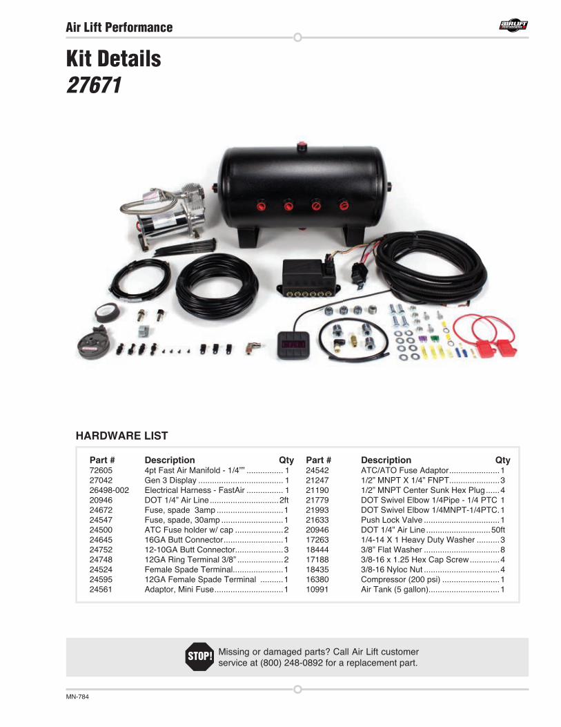
Kit Details 27671
Part # Description Qty72605 4pt Fast Air Manifold - 1/4”” ................ 127042 Gen 3 Display ..................................... 126498-002 Electrical Harness - FastAir ................ 120946 DOT 1/4” Air Line ..............................2ft24672 Fuse, spade 3amp .............................124547 Fuse, spade, 30amp ...........................124500 ATC Fuse holder w/ cap .....................224645 16GA Butt Connector ..........................124752 12-10GA Butt Connector.....................324748 12GA Ring Terminal 3/8” ....................224524 Female Spade Terminal......................124595 12GA Female Spade Terminal ..........124561 Adaptor, Mini Fuse ..............................1
Part # Description Qty24542 ATC/ATO Fuse Adaptor ......................121247 1/2” MNPT X 1/4” FNPT ......................321190 1/2” MNPT Center Sunk Hex Plug ......421779 DOT Swivel Elbow 1/4Pipe - 1/4 PTC 121993 DOT Swivel Elbow 1/4MNPT-1/4PTC .121633 Push Lock Valve .................................120946 DOT 1/4” Air Line ............................50ft17263 1/4-14 X 1 Heavy Duty Washer ..........318444 3/8” Flat Washer .................................817188 3/8-16 x 1.25 Hex Cap Screw .............418435 3/8-16 Nyloc Nut .................................416380 Compressor (200 psi) .........................110991 Air Tank (5 gallon)...............................1
HARDWARE LIST
Missing or damaged parts? Call Air Lift customer service at (800) 248-0892 for a replacement part.
STOP!


TABLE OF CONTENTS
Installing the AutoPilot V2 Kit . . . . . . . . . . . . . . . . . . . . 4
NPT Assembly Instructions . . . . . . . . . . . . . . . . . . . . . . 6
Air Line and Fittings Helpful Hints . . . . . . . . . . . . . . . . . 6
Setup and Calibration . . . . . . . . . . . . . . . . . . . . . . . . . . . 7
Program Presets . . . . . . . . . . . . . . . . . . . . . . . . . . . . . . . 8
Troubleshooting Guide . . . . . . . . . . . . . . . . . . . . . . . . . . 9
Leak Testing and Detection . . . . . . . . . . . . . . . . . . . . . . 9
Use the System . . . . . . . . . . . . . . . . . . . . . . . . . . . . . . . . 12
Electrical Schematic . . . . . . . . . . . . . . . . . . . . . . . . . . . . 13
Warranty and Returns Policy . . . . . . . . . . . . . . . . . . . . . 14
Replacement Information . . . . . . . . . . . . . . . . . . . . . . . . 14
Contact Information . . . . . . . . . . . . . . . . . . . . . . . . . . . . 14
Manifold Template . . . . . . . . . . . . . . . . . . . . . . . . . . . . . . 15
AutoPilot V2 Remote Control Unit . . . . . . . . . . . . . . . . . 17
16380 Compressor Template . . . . . . . . . . . . . . . . . . . . . 19
4 MN-754
Air Lift Performance
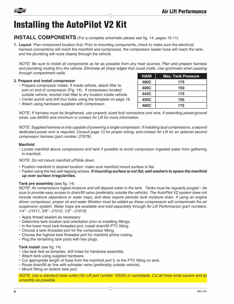
INSTALL COMPONENTS (For a complete schematic please see fig. 14, pages 10-11)
1. Layout Plan component location first. Prior to mounting components, check to make sure the electrical harness connections will reach the manifold and compressor, the compressor leader hose will reach the tank, and the plumbing will route cleanly through the vehicle.
NOTE: Be sure to install all components as far as possible from any heat sources. Plan and prepare harness and plumbing routing thru the vehicle. Eliminate all sharp edges that could chafe. Use grommets when passing through compartment walls.
2. Prepare and install compressor• Prepare compressor intake. If inside vehicle, attach filter to
port on end of compressor (Fig. 14). If compressor located outside vehicle, snorkel inlet filter to dry location inside vehicle.
• Center punch and drill four holes using the template on page 19.• Attach using hardware supplied with compressor.
NOTE: If harness must be lengthened, use properly sized butt connectors and wire. If extending power/ground wires, use 8AWG wire minimum or contact Air Lift for more information.
NOTE: Supplied harness is only capable of powering a single compressor. If installing dual compressors, a second dedicated power wire is required. Consult page 13 for proper wiring, and contact Air Lift for an optional second compressor harness (part number: 27679).
Manifold• Locate manifold above compressors and tank if possible to avoid compressor ingested water from gathering
in manifold.
NOTE: Do not mount manifold uPSIde down.
• Position manifold in desired location: make sure manifold mount surface is flat.• Fasten using the two self-tapping screws. If mounting surface is not flat, add washers to space the manifold
up over surface irregularities.
Tank pre assembly (see fig. 14)NOTE: Air compressors ingest moisture and will deposit water in the tank. Tanks must be regularly purged – be s re to provi e eas access to rain fill valve (pre era l o tsi e t e ve icle). The AutoPilot V2 system does not include moisture separators or water traps, and does require periodic tank moisture drain. If using an engine
riven compressor proper oil an water filtration m st e a e as t ese compressors will contaminate t e air suspension system. Water traps are available and sold separately through Air Lift Performance (part numbers: 1/4” - 21011, 3/8” - 21012, 1/2” - 21013)
• Apply thread sealant as necessary.• Determine tank location and orientation prior to installing fittings.• In the lower most tank threaded port, install drain/fill PTC fitting.• Choose a tank threaded port for the compressor fitting.• Choose the highest tank threaded port for manifold airline routing. • Plug the remaining tank ports with hex plugs.
Tank install (see fig. 14)• Use tank feet as template, drill holes for hardware assembly.• Attach tank using supplied hardware.• Cut appropriate length of hose from the manifold port 5, to the PTC fitting on tank.• Route drain/fill air line with schrader valve (preferably outside vehicle). • Mount fitting on bottom tank port.
NOTE: Use a standard hose cutter (Air Lift part number 10530) or razorblade. Cut all hose ends square and as smoothly as possible.
Installing the AutoPilot V2 Kit
VIAIR Max. Tank Pressure380C 175400C 150444C 175450C 150480C 175

5MN-754
Air Lift Performance
INSTALL HARNESS1. Disconnect battery ground while installing system.
2. Compressor / manifold connections (see fig. 14)• Attach the manifold connector, it will click” into place once fully seated.• Mount the compressor relay in a preferred location using a self-tapping screw.• Cut off the spade and eyelet from the compressor power and ground wires.• Strip ” of wire casing from the compressor wires.• Strip ” of wire casing from the black and pink harness wires.
NOTE: Use an appropriate terminal crimp tool to ensure a good connection.
• Using butt connector attach the RED compressor wire to the PINK harness wire.• Using butt connector attach the BLACK compressor wire to the BLACK harness wire.• Carefully apply heat (preferably with a heat gun) to seal these connections.
3. Battery / ignition connections (see fig. 14)• Identify the power, ground, + ignition leg of the harness.
• Ground: 10AWG black wire Power: 10AWG red wire Ignition: 18AWG pink wire.• Route power and ground leg of the harness free from any heat source to the battery.• Using butt connector attach red wire to fuse holder. • Attach 3/8” eyelet to the other end of the fuse holder and attach to positive battery (+) terminal.• Attach 3/8” eyelet to the black wire and attach to battery ground.• Route the 18AWG pink wire to a key switched IGNITION source that remains on during cranking. Examples
include: ECU, fuel pump. Do not select an accessory source. If the AutoPilot V2 display shuts off while starting vehicle this is not a true ignition source.
• Using butt connector attach the pink ignition wire to a fuse holder.• Select ignition source and attach the fused ignition wire.• Use fuse adaptors as necessary.
4. Display• Route display cable as desired to the preferred operating location.• Attach the display cable to the main harness cable (small white 3 cavity connector).
5. Reconnect battery
INSTALL AIR LINES NOTE: Use a standard hose cutter (Air Lift part number 10530) or razorblade. Cut all hose ends square and as smoothly as possible.
Route and attach air lines to air springs• Route air lines free from abrasive edges and heat sources.• Attach manifold port FL or 1 to the front, drivers side left spring.• Attach manifold port FR or 2 to the front, passengers side right spring.• Attach manifold port RL or 3 to the rear, drivers side left spring.• Attach manifold port RR or 4 to the rear, passengers side right spring.• Attach manifold port T or 5 to the PTC fitting previously installed on the tank.• Manifold port E or 6 is the exhaust port.
• Port E can be left open, or routed to a preferred exhaust location.
ir lines s o l e p s e in firml wit a slig t ac an ort rotational twist c ec t e connection pulling on each line to verify a robust connection.
elease t e air line rom t e fitting releasing air p s ing on t e line epressing t e ring towar s t e fitting an t en p lling t e ose o t o t e fitting.

6 MN-754
Air Lift Performance
Table 1
Torque Specifications
Fitting Size Dash Size Turns Past Finger Tight
Torque lb/ft
1/8” NPT -02 1.5 - 3.0 12
1/4” NPT -04 1.5 - 3.0 25
3/8” NPT -06 1.5 - 3.0 40
1/2” NPT -08 1.5 - 3.0 54
3/4” NPT -12 1.5 - 3.0 78
1” NPT -16 1 - 2.5 112
1 ” NPT -20 1 - 2.5 154
1½” NPT -24 1 - 2.5 211
2” NPT -32 1 - 2.5 300
1. Inspect port and fitting to ensure both are free of contaminants and excessive burrs and nicks.
2. Apply a stripe of liquid pipe sealant around the male threads leaving the first two threads uncovered.
3. Screw finger tight into the port.
4. Wrench tighten the fitting to the correct turns past finger tight position (see table 1).
CAUTION: NEVER BACK OFF AN INSTALLED PIPE FITTING TO ACHIEVE PROPER ALIGNMENT. LOOSENING INSTALLED PIPE FITTINGS WILL CORRUPT THE SEAL AND CONTRIBUTE TO LEAKAGE AND FAILURE.
NPT Assembly Instructions
Air Line and Fittings Helpful TipsHose bend radius
• 3/8” hose 1.5” hose bend radius
• 1/4” hose 1” hose bend radius
ose to fittin• No side loading on fitting from hose.
• Hose straight for 1” before bending.
Hose cutting• Cut hose perpendicular to hose length.
• Inspect hose for scratches that run lengthwise on hose prior to insertion.
• Use proper hose cutter, cigar cutter, or razor on flat surface.
DOT/SAEJ844 air brake hose data• Maximum working pressure of 175 PSI.
• Not to be used for frame (body) to un-sprung mass connection, use a braided leader hose for this moving connection.

7MN-754
Air Lift Performance
SYSTEM CALIBRATION AND SETTINGS1. Key-on/power up, and compressor should come on to fill the
tank. Check to make sure system is triggered by IGNITION source. While starting the engine, the system should be ON. If not, please refer back to Install Harness” on page 5.
2. Press buttons 1 and 5 at the same time (1+5) and hold for 5-10 seconds until settings and diagnostics mode main page appears (fig. 2).
3. Press button 1 (TANK ADJUST). Set tank pressure preference by pressing MIN and MAX up/down buttons (fig. 3). Press buttons 1+5 to exit to settings and diagnostics mode.
NOTE: If tank MAX settings are changed, a system re-calibration is necessary for optimal performance.
Calibrate to your vehicle
NOTE: System will automatically deflate to 0 PSI and inflate to 100 PSI during calibration.
4. Press button 2 to enter CALIBRATE (fig. 4). Press SYSTEM CAL (button 1), follow instructions to calibrate AutoPilot V2 system to your vehicle. Once calibration is complete, Press buttons 1+5 to exit to the settings and diagnostics mode.
5. Press button 3 to enter BACKLIGHT (fig. 5). Set display backlight to your preference by pressing the + and on R (Red), G (Green), B (Blue). Press buttons 1+5 to exit to the settings and diagnostics mode.
Automatic preset maintenance
6. Press button 4 to enter PRESET MAINTAIN (fig. 6). Press button 8 to turn ON or OFF. When ON, this function actively monitors air spring pressure and will fill to maintain active preset pressure.
NOTE: This function will not exhaust pressure. If air spring pressure is higher than preset target, only the operator pressing the preset button again will activate the system to exhaust air spring pressure (for safety). Press buttons 1+5 to exit.
NOTE: PRESET MAINTAIN should be off for performance/track driving or if operating in extremely hilly areas.
AutoPilot V2 is an advanced pressure-based air suspension control system, that uses state-of-the-art software algorithms to calibrate or map the control system to your vehicle. Once the system is calibrated, the algorithm predicts required valve open time” to move the air suspension to achieve preset target pressures. AutoPilot V2 has 8 programmable presets, allowing the user to input 8 different combinations of the 4 corner air spring pressures.
After installing AutoPilot V2 in your vehicle, please follow the steps below to properly setup your new system! If changes are made after installing and calibrating the system such as changes to air springs, lines, tank, compressor, or other vehicle modifications the system must be recalibrated.
Setup and Calibration
fig. 1
1 2 3 4
5 6 7 8
RRLRRFLFT
Button Definition
ADJBACKLIGHT+ + +
- - -R G B
fig. 5
PRESET MAINTAIN?
ON
fig. 6
MAX 175MIN 145fig. 3
TANK ADJUSTCALIBRATEBACKLIGHTPRESET MAIN
1234
.
.
.
.
fig. 2
CALIBRATION MENU1 SYSTEM CAL2 ADJUST SYSTEM..fig. 4

8 MN-754
Air Lift Performance
7. Press button 8 to toggle to settings page 2 (fig. 7).
8. Press button 5 to run a compressor test (fig. 8). This function will exhaust the tank to your specified MIN tank pressure, then turn ON the compressor and measure its inflate time to achieve MAX pressure. AutoPilot V2 will record this fill time, allowing the operator to compare future fill times to determine compressor performance. Press buttons 1+5 to exit.
9. Press button 6 to view the number of hours the compressor has been running.
Rise on start
10. Press button 7 to enter RISE ON START (fig. 9). This function will automatically activate valves to achieve preset 1 target pressures when the vehicle is keyed-on. This function allows the operator to drive away seconds after vehicle is started. Press buttons 1+5 to exit.
11. Press button 8 to toggle between PSI and BAR pressure units and check software version. Press buttons 1+5 to exit.
NOTE: BAR stands for DeciBar values.
12. Press buttons 1+5 to exit settings and diagnostics you are now ready to create presets!
TANK PRESSURE RANGE140-175 PSI
PROCEED? YES NO
COMP TESTCOMP TIMERISE ON STARTPSI / BAR & SWV
5678
....
RISE ON START?
ON
fig. 7
fig. 8
fig. 9
NOTE: Preset 1 should always be entered as the desired ride pressure for the RISE ON START function.
1. Determine ride pressures: press buttons 1+5 to toggle display to MANUAL mode. Manually activate each corner (see MANUAL mode section page 12) to achieve desired normal driving” ride pressure. (fig. 10)
8 programmable presets
2. Program preset 1: press buttons 1+5 to toggle display to PRESET mode. Press and hold button 1 to set 1. Release button and actual air spring pressures will appear (fig. 11). Fine-tune the pressures by pressing up/down buttons. Press + hold to scroll. Press buttons 1+5 to exit.
NOTE: If your system is not hitting presets quickly, change the ADJ” value. Enter Settings and Diagnostics” mode (press Button 1+5 for more than 5 seconds), press #2 CALIBRATE, then ADJUST SYSTEM to toggle the value between 0 and 10 higher values increase system fill rates to overshoot target pressures.
3. You are now free to program the additional 7 presets to desired pressures. Typical presets can be:
• Low”: set pressures to the lowest possible pressures for extreme low driving stance
• Front up”: for speed bump or driveway clearance
• Rear up”: for added load of passengers, equipment
• Play”: for those that want to enjoy their air suspension
Program Presets
64 66 82 80150
fig. 10
65 65 80 80PRESET 1
EDIT
fig. 11
5 100 5 100
EDIT
PRESET 6
fig. 12
fig. 1
1 2 3 4
5 6 7 8
RRLRRFLFT
Button Definition

9MN-754
Air Lift Performance
freedom, AutoPilot V2 has a special function that recognizes side-to-side presets. When left side pressures are equal, and right side pressures are equal but 25PSI different than left, the algorithm will activate side to side instead of front to back. It will also equalize all air spring pressures when exiting the play” preset, conserving air by using the high pressure side to inflate the low pressure side. Pairing two play” presets together allows side-to-side activation that consumes far less air than manual mode activation would consume (Figs. 12 13).
100 5 100 5
EDIT
PRESET 7
fig. 13
Troubleshooting GuideFor further technical assistance please contact our customer service department by calling (800) 248-0892, Monday through Friday. For calls from outside the USA or Canada, our local number is (517) 322-2144.
PROBLEM CAUSE SOLUTIONCompressor doesn’t run.
Compressor runs all the time.
Nothing happens when the vehicle is key-on ignition active.
The display does not light up.
Compressor runs all the time but doesn’t fill the tank.
Air spring or tank leak.
Display shows UNSUCCESSFUL
There is a blown fuse or relay, bad ground, or poor electrical connections.
The compressor relay is defective or there is a leak.
There is a blown fuse or a poor connection.
There is a blown fuse or a poor connection.
Compressor inline check valve fitting has been overtorqued.
Fitting seal or air line compromised.
Calibration may need to be adjusted or system may need to be recalibrated .
Tank pressure settings changed.
Vehicle load changed significantly.
Air springs/air lines/tank changed.
Replace the fuse, check the ground wire, or check the compressor connector.
Replace the relay or locate the leak and repair.
Replace the fuses and check the electrical connections.
Replace the fuses and check the electrical connections.
Loosen fitting and check again. Replace if needed.
Check to make sure air lines are seated in connectors. Inspect fittings with soapy water. Trim hose or re-seal fitting.
Adjust ADJ value or recalibrate system to reduce number of iterations.
Attempt recalibration.
Leak Testing and DetectionLeak detection
1. Pressure change is directly proportional to temperature change in a container that is not leaking.
a. For every 10 Fahrenheit decrease the pressure by 2 PSI.
b. All other pressure changes are due to air exiting the system.
2. Spray soapy water on suspect fittings and hose connections.
3. Wipe down with rag to clean.
4. Soapy water recipe
a. 1/5 Dawn brand dish soap to 4/5 water.
b. Dawn brand dish soap will not corrode the metals (aluminum, brass, steel) it comes in contact with.
T SA 844 oses an fittin s (in ustry stan ar )1. Allowable leak rate 7 sccm @-40 (per fitting)
2. Examples
a. 150 PSI in a 2.5 gallon tank @ -40 for 12 hours 142.17 PSI
b. 150 PSI in a 5 gallon tank @ -40 for 12 hours 146.08 PSI
c. 100 PSI in a 141 in 3 (cubic inches) spring @-40 for 12 hours 67.94 PSI
• Assumption is that the spring keeps constant volume

10 MN-754
Air Lift Performance
or
r
o
or
r
o
A
or
r
o
or
r
o
LE
FT
RIG
HT
LE
FT
RIG
HT
NO
TE
: Ar
ro
o
o
o o
r
ror
A
r
r
r
o
oo
o
o
r
o
ro o
r
r
A
A
A
A
+
-
AA
A
r
B
oor
Dr
o
oo
12
34
56
78RR
LRRF
LF
o
o
o
oo
Rel
ay s
chem
atic
ref
eren
ce
3030
86868585
8787
Co
ror
Co
ror
o
oB
r
or
o
oB
r
or
A A
B
B
AA
rA
o o
rA
o o
A
A
AA
AA
A
Ign
itio
n S
ou
rce
(on
wh
ile c
ran
kin
g)
Co
nn
ect
dir
ect
to b
atte
ryP
refe
rred
o r
o
r
o
ro
r
r
or
r
C
o
or
or
r
A
or
r
o
or
r
o
A
or
r
o
or
r
o
LE
FT
RIG
HT
LE
FT
RIG
HT
NO
TE
: Ar
ro
o
o
o o
r
ror
A
r
r
r
o
oo
o
o
r
o
ro o
r
r
A
A
A
A
+
-
AA
A
r
B
oor
Dr
o
oo
12
34
56
78RR
LRRF
LF
o
o
o
oo
Rel
ay s
chem
atic
ref
eren
ce
3030
86868585
8787
Co
ror
Co
ror
o
oB
r
or
o
oB
r
or
A A
B
B
AA
rA
o o
rA
o o
A
A
AA
AA
A
Ign
itio
n S
ou
rce
(on
wh
ile c
ran
kin
g)
Co
nn
ect
dir
ect
to b
atte
ryP
refe
rred
o r
o
r
o
ro
r
r
or
r
C
o
or
or
r
A
fig. 14

11MN-754
Air Lift Performance
or
r
o
or
r
o
A
or
r
o
or
r
o
LE
FT
RIG
HT
LE
FT
RIG
HT
NO
TE
: Ar
ro
o
o
o o
r
ror
A
r
r
r
o
oo
o
o
r
o
ro o
r
r
A
A
A
A
+
-
AA
A
r
B
oor
Dr
o
oo
12
34
56
78RR
LRRF
LF
o
o
o
oo
Rel
ay s
chem
atic
ref
eren
ce
3030
86868585
8787
Co
ror
Co
ror
o
oB
r
or
o
oB
r
or
A A
B
B
AA
rA
o o
rA
o o
A
A
AA
AA
A
Ign
itio
n S
ou
rce
(on
wh
ile c
ran
kin
g)
Co
nn
ect
dir
ect
to b
atte
ryP
refe
rred
o r
o
r
o
ro
r
r
or
r
C
o
or
or
r
A
or
r
o
or
r
o
A
or
r
o
or
r
o
LE
FT
RIG
HT
LE
FT
RIG
HT
NO
TE
: Ar
ro
o
o
o o
r
ror
A
r
r
r
o
oo
o
o
r
o
ro o
r
r
A
A
A
A
+
-
AA
A
r
B
oor
Dr
o
oo
12
34
56
78RR
LRRF
LF
o
o
o
oo
Rel
ay s
chem
atic
ref
eren
ce
3030
86868585
8787
Co
ror
Co
ror
o
oB
r
or
o
oB
r
or
A A
B
B
AA
rA
o o
rA
o o
A
A
AA
AA
A
Ign
itio
n S
ou
rce
(on
wh
ile c
ran
kin
g)
Co
nn
ect
dir
ect
to b
atte
ryP
refe
rred
o r
o
r
o
ro
r
r
or
r
C
o
or
or
r
A

12 MN-754
Air Lift Performance
Now that your system is set up, it’s time to use it. If changes are made after installing and calibrating the system such as changes to air springs, lines, tank, or compressor the system must be recalibrated.
There are two modes: PRESET and MANUAL. Pressing buttons 1 and 5 together will toggle between modes. After 10 seconds of non-use, the display enters standby where the LCD dims. Any button hit will wake-up” the display and allow users to activate the system. See mode operation below for more details.
PRESET mode
• First button press will display the programmed preset. Users can quickly view each preset prior to activating to make sure they are selecting the desired preset.
• A 2nd button press of the same preset will activate it. The system will iterate up to 6 times to achieve the preset target pressures by +/- 3 PSI. Display shows PLEASE WAIT as it iterates, then will flash SUCCESSFUL when achieved or UNSUCCESSFUL if not able to achieve the target pressure window (NOTE: if your system is not hitting presets quickly, change the ADJ value). Enter Settings and Diagnostics mode (press buttons 1+5 for more than 5 seconds), press button 2 (CALIBRATE), then ADJUST SYSTEM to toggle the value between 0 and 10. Higher values increase system fill rates to overshoot target pressures.
Micro adjust to ±1 PSI: more acc rac is esire o le press t e same preset an t e s stem will refine pressures closer to target .
Use the System
fig. 16 MANUAL Modefig. 15 PRESET Mode
29999 99 99 99
1 2 3 4
8765
103 82 75 80150299
99 99 99 99
1 2 3 4
8765
103 82 75 80150
MANUAL mode
MANUAL mode allows the user to fill or exhaust each spring. The display will show arrows above and below the pressures to indicate manual control mode. The arrow will be solid when the spring is filling/exhausting, and just an outline when not active.
MANUAL mode with Easy Control™Tap
The system detects button press time. For a very short ( 0.1sec) duration press, the system will open the valves for a defined burst”, changing pressure minimally so users can fine-tune their pressures. For a longer than 0.1 sec duration press, the valves open as long as you hold the button down. If a button is held active, the fill/exhaust will time out after 10 seconds.
• Fill springs: buttons 1 - 4
• Exhaust springs: buttons 5 - 8

13MN-754
Air Lift Performance
Electrical Schematic
fig. 17
AU
TOP
ILO
T V
2 G
EN
3 P
RE
SS
UR
E C
ON
TRO
L
* Sold seperately Air Lift Part Number 27679
AU
TOP
ILO
T V
2 S
EC
ON
D C
OM
PR
ES
SO
R H
AR
NE
SS
*

14 MN-754
Air Lift Performance
Contact InformationIf you have any questions, comments or need technical assistance contact our customer service department by calling (800) 248-0892, Monday through Friday. For calls from outside the USA or Canada, our local number is (517) 322-2144. You may also contact customer service anytime by e-mail at [email protected].
For inquiries by mail, our address is PO Box 80167, Lansing, MI 48908-0167. Our shipping address for returns is 2727 Snow Road, Lansing, MI 48917.
You may also contact our sales team anytime by e-mail at [email protected] or on the web at www.airliftperformance.com.
Replacement InformationIf you need replacement parts, contact the local dealer or call Air Lift customer service at (800) 248-0892. Most parts are immediately available and can be shipped the same day.
Contact Air Lift Company customer service at (800) 248-0892 first if:
Air Lift Company warrants its performance products for one year to the original purchaser against manufacturing defects one year from the date of purchase when used on cars and trucks as specified under normal operating conditions. The warranty does not apply to products that have been improperly applied, improperly installed, or which have not been maintained in accordance with installation instructions furnished with all products. The consumer will be responsible for removing (labor charges) the defective product from the vehicle and returning it, transportation costs prepaid, to the dealer from which it was purchased or to Air Lift Company for verification.
Air Lift will repair or replace, at its option, defective products or components. A minimum $10.00 shipping and handling charge will apply to all warranty claims. Before returning any defective product, you must call Air Lift at (800) 248-0892 in the U.S. and Canada (elsewhere, (517) 322-2144) for a Returned Materials Authorization (RMA) number. Returns to Air Lift can be sent to: Air Lift Company • 2727 Snow Road • Lansing, MI • 48917.
Product failures resulting from abnormal use or misuse are excluded from this warranty. The loss of use of the product, loss of time, inconvenience, commercial loss or consequential damages are not covered. The consumer is responsible for installation/reinstallation (labor charges) of the product. Air Lift Company reserves the right to change the design of any product without assuming any obligation to modify any product previously manufactured.
This warranty gives you specific legal rights and you may also have other rights that may vary from state-to-state. Some states do not allow limitations on how long an implied warranty lasts or allow the exclusion or limitation of incidental or consequential damages. The above limitation or exclusion may not apply to you. There are no warranties, expressed or implied including any implied warranties of merchantability and fitness, which extend beyond this warranty period. There are no warranties that extend beyond the description on the face hereof. Seller disclaims the implied warranty of merchantability. Dated proof of purchase required.
Warranty and Returns Policy
• Parts are missing from the kit.• Technical assistance on installation or operation is
needed.
• Broken or defective parts in the kit.• Wrong parts in the kit.• Have a warranty claim or question.
Contact t e retai er ere t e it as purc ase :
• If it is necessary to return or exchange the kit for any reason.• If there is a problem with shipping, if shipped from the retailer.• If there is a problem with the price.

15MN-754
Air Lift Performance
Manifold Template

16 MN-754
Air Lift Performance
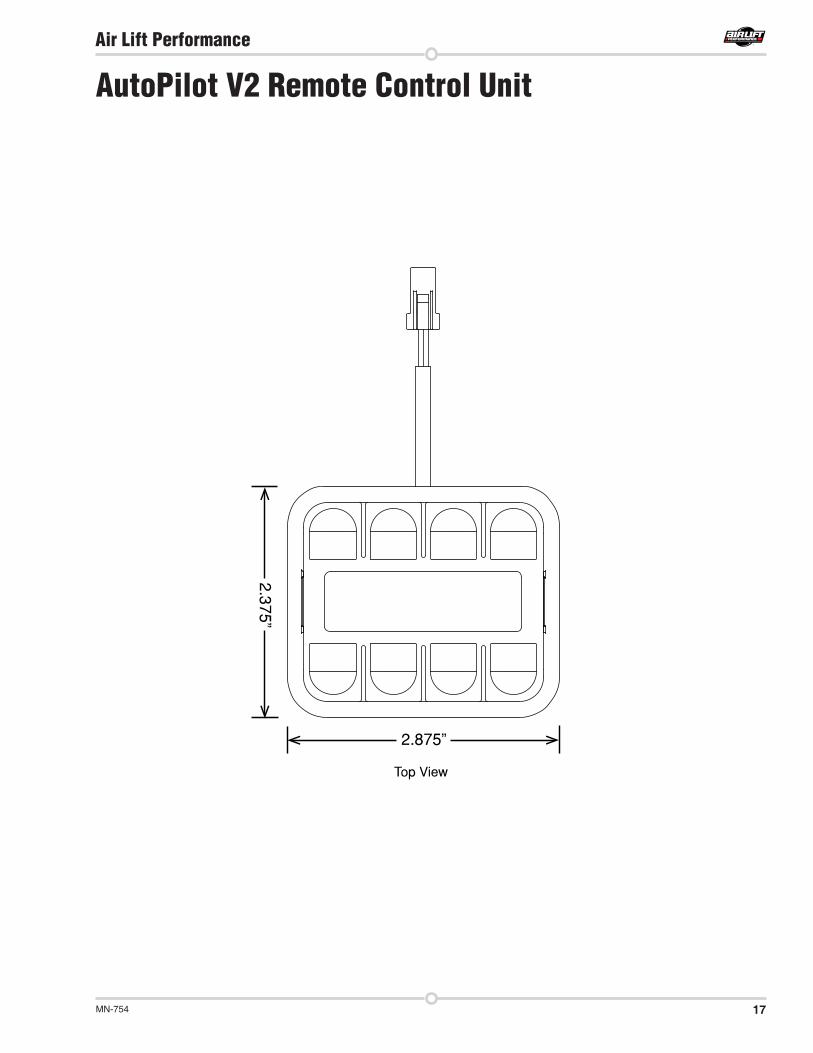
17MN-754
Air Lift Performance
AutoPilot V2 Remote Control Unit
o

18 MN-754
Air Lift Performance

19MN-754
Air Lift Performance
16380 Compressor Template
6.6900
3.3100
HOLE PATTERN FOR BOTTOM OF 16380 COMPRESSOR

Air Lift Company • 2727 Snow Road • Lansing, MI 48917 or PO Box 80167 • Lansing, MI 48908-0167 Toll Free (800) 248-0892 • Local (517) 322-2144 • Fax (517) 322-0240 • www.airliftperformance.com
Thank you for purchasing Air Lift Performance products!
Printed in the USA
Need Help?Contact our customer service department by calling (800) 248-0892, Monday through Friday. For calls from outside the USA or Canada, our local number is (517) 322-2144.