Interface-Related Damage Evolution in Air-Plasma-Sprayed ...
Upload
merve-saimlerCategory
view
10download
0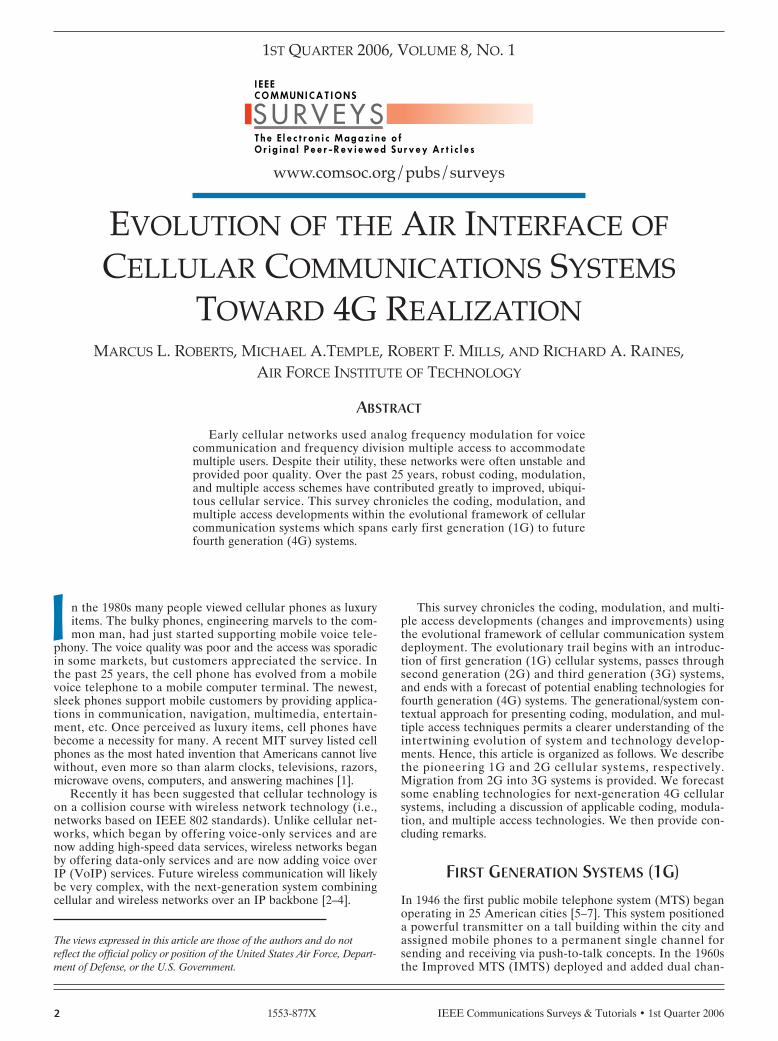
IEEE Communications Surveys & Tutorials • 1st Quarter 20062
n the 1980s many people viewed cellular phones as luxuryitems. The bulky phones, engineering marvels to the com-mon man, had just started supporting mobile voice tele-
phony. The voice quality was poor and the access was sporadicin some markets, but customers appreciated the service. Inthe past 25 years, the cell phone has evolved from a mobilevoice telephone to a mobile computer terminal. The newest,sleek phones support mobile customers by providing applica-tions in communication, navigation, multimedia, entertain-ment, etc. Once perceived as luxury items, cell phones havebecome a necessity for many. A recent MIT survey listed cellphones as the most hated invention that Americans cannot livewithout, even more so than alarm clocks, televisions, razors,microwave ovens, computers, and answering machines [1].
Recently it has been suggested that cellular technology ison a collision course with wireless network technology (i.e.,networks based on IEEE 802 standards). Unlike cellular net-works, which began by offering voice-only services and arenow adding high-speed data services, wireless networks beganby offering data-only services and are now adding voice overIP (VoIP) services. Future wireless communication will likelybe very complex, with the next-generation system combiningcellular and wireless networks over an IP backbone [2–4].
This survey chronicles the coding, modulation, and multi-ple access developments (changes and improvements) usingthe evolutional framework of cellular communication systemdeployment. The evolutionary trail begins with an introduc-tion of first generation (1G) cellular systems, passes throughsecond generation (2G) and third generation (3G) systems,and ends with a forecast of potential enabling technologies forfourth generation (4G) systems. The generational/system con-textual approach for presenting coding, modulation, and mul-tiple access techniques permits a clearer understanding of theintertwining evolution of system and technology develop-ments. Hence, this article is organized as follows. We describethe pioneering 1G and 2G cellular systems, respectively.Migration from 2G into 3G systems is provided. We forecastsome enabling technologies for next-generation 4G cellularsystems, including a discussion of applicable coding, modula-tion, and multiple access technologies. We then provide con-cluding remarks.
FIRST GENERATION SYSTEMS (1G)In 1946 the first public mobile telephone system (MTS) beganoperating in 25 American cities [5–7]. This system positioneda powerful transmitter on a tall building within the city andassigned mobile phones to a permanent single channel forsending and receiving via push-to-talk concepts. In the 1960sthe Improved MTS (IMTS) deployed and added dual chan-
I
S U R V E Y SI E E E C O M M U N I C A T I O N S
T h e E l e c t r o n i c M a g a z i n e o f O r i g i n a l P e e r - R e v i e w e d S u r v e y A r t i c l e s
MARCUS L. ROBERTS, MICHAEL A.TEMPLE, ROBERT F. MILLS, AND RICHARD A. RAINES, AIR FORCE INSTITUTE OF TECHNOLOGY
ABSTRACT
Early cellular networks used analog frequency modulation for voicecommunication and frequency division multiple access to accommodatemultiple users. Despite their utility, these networks were often unstable andprovided poor quality. Over the past 25 years, robust coding, modulation,and multiple access schemes have contributed greatly to improved, ubiqui-tous cellular service. This survey chronicles the coding, modulation, andmultiple access developments within the evolutional framework of cellularcommunication systems which spans early first generation (1G) to futurefourth generation (4G) systems.
EVOLUTION OF THE AIR INTERFACE OFCELLULAR COMMUNICATIONS SYSTEMS
TOWARD 4G REALIZATION
1ST QUARTER 2006, VOLUME 8, NO. 1
www.comsoc.org/pubs/surveys
1553-877X
The views expressed in this article are those of the authors and do notreflect the official policy or position of the United States Air Force, Depart-ment of Defense, or the U.S. Government.
IEEE Communications Surveys & Tutorials • 1st Quarter 2006 3
nels for sending and receiving (i.e., full-duplexing) [5–7].However, the system was impractical because of capacity con-straints. In New York City only 12 calls could be simultane-ously supported over a 1,000 square mile area [5].
Demonstration of the cellular concept soon followed in1968 at Bell Laboratories [5, 7]. The cellular concept featuredtwo-way communication using a hexagonal, N-cell frequencyreuse pattern with intracellular mobile stations (MS) con-trolled by a base station (BS). Three components of the cellu-lar concept bear further mention because they contributegreatly to increased capacity, the limiting factor in mobiletelephony systems like IMTS: frequency reuse, sectorization,and handoff. By lowering the BS power in a given cell (i.e.,reducing the cell size), the same frequency can be reused byanother BS in a geographically remote cell. Furthermore,within a cell, directional antennas can be added to the BS tosector the cell (e.g., 60° or 120° sectors) and introduce greatercapacity. Finally, handoff between base stations (hard or soft)dramatically increases the mobility afforded the customer,greatly expanding the user access area and also increasingcapacity. For more information on other capacity increasingmeasures and cellular concepts, the reader is directed to [5].
Numerous discoveries paved the way for modern cellularnetworks, but the true enabler of cellular communication wasthe invention of the microprocessor in 1971 [8]. This devicewas powerful enough to be embedded in a radio unit and pro-vide the necessary processing power. Based on this develop-ment, 1G cellular systems, characterized by their analognature, began operating within a decade following this inven-tion.
The first commercial 1G cellular system was the MobileCommunication System L1 (MCS-L1), introduced in Japan in1979 by Nippon Telegraph and Telephone (NTT) [5, 7, 9, 10].MCS-L1 uses 600 frequency-modulated (FM) full duplex 25kHz channels in the 800 MHz band. In fact, all early 1G sys-tems used FM and had channel bandwidths of 25 or 30 kHzdespite the fact that two-way radios functioned with much lessbandwidth using amplitude modulation (AM). The designerswanted voice quality comparable to wired telephones. Thus,they chose FM over AM because of its better noise immunity,despite the fact that FM systems require more bandwidth.Using frequency deviations of 6-12 kHz [5, 11] coupled withaudio bandwidths of 3 kHz necessitated the use of 25 or 30kHz channels. Designers also incorporated frequency parti-tioning to separate users, i.e., frequency division multipleaccess (FDMA). For MCS-L1, a 15 MHz spectral band waspartitioned into 600 25 kHz channels.
The first commercial U.S. 1G cellular system arrived in1983 when the Advanced Mobile Phone Service (AMPS) wasintroduced [5]. AMPS supports 832 FM full duplex 30 kHzchannels in the 800 MHz band. AMPS also maintains a con-trol channel at 10 kb/s, modulated using frequency shift key-ing (FSK) [5, 11]. To protect the FSK data on the controlchannel, a Manchester (or biphase) coding is applied alongwith a block code [5].
European 1G systems contain similar characteristics to theJapanese MCS-L1 and American AMPS systems [5, 7, 11].Nordic Mobile Telephone (NMT) began operation in Scandi-navia in 1981 and supports 1000 FM 25 kHz channels in the900 MHz band. Total Access Communication System (TACS)and Extended TACS (ETACS) began operation in the UnitedKingdom in 1982 and 1985 and are very comparable to AMPS.Slightly smaller bandwidths yield slight decreases in signal-to-noise ratio (SNR) and coverage compared to AMPS. C-450began operation in Germany in 1985 and supports 573 FM 10kHz frequency-interleaved channels in the 450 MHz band.Radiocom 2000 began operation in France in 1985 and sup-
ports 560 FM 12.5 kHz frequency-interleaved channels in the200 MHz band.
Despite frequency reuse benefits, capacity remained a keylimitation of 1G systems. Therefore, in the late 1980s newAmerican and Japanese 1G systems reduced channel band-width in an attempt to improve capacity. In North Americanarrowband AMPS (NAMPS) deployed, which boosted thecapacity three-fold by splitting each 30 kHz AMPS channelinto three 10 kHz channels (frequency deviation decreasedfrom 12 to 5 kHz) [5, 12]. In Japan NTT deployed a highcapacity system, which quadrupled capacity by reducing chan-nel bandwidth from 25 to 6.25 kHz (using smaller channelsand frequency interleaving) [11]. Japan also deployed theJapanese TACS (JTACS) and narrowband TACS (NTACS)systems, which are very similar to the NAMPS and NTT high-capacity systems.
SECOND GENERATION SYSTEMS (2G)In the late 1980s very large scale integration (VLSI) and sig-nal processing technology matured, paving the way for thedigital era. Just as the microprocessor was the enabler for 1Gcellular, the digital signal processor (DSP) was the enabler for2G cellular. Application specific integrated circuits (ASICs)led to reduced mobile phone sizes, and new signal processingfeatures (with faster chips) contributed to soaring computingrates [13]. At the same time, 1G systems were reaching theircapacity in city markets. Hence, as digital technology becamemore prevalent, analog 1G systems were progressivelyreplaced by newer 2G cellular systems beginning in the early1990s. 2G systems are characterized by their digital nature,offering better voice quality and rudimentary data services.2G systems were designed for voice communication operationvia circuit switching to guarantee link availability for tele-phone calls.
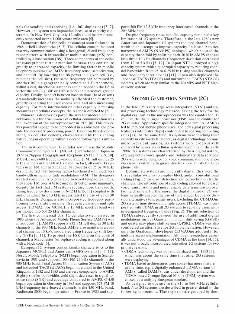
Because 2G systems are inherently digital, they were thefirst cellular systems to employ block and/or convolutionalcoding (Fig. 1) for error detection and correction on trafficchannels. The introduction of such coding allowed for clearervoice transmissions and more reliable data transmission overfading channels. Furthermore, the digital nature of 2G sys-tems naturally enabled the use of time and/or frequency divi-sion alternatives to separate users. Excluding the CDMAOne2G system, time division multiple access (TDMA) was incor-porated with FDMA in all 2G systems to separate users with-in designated frequency bands (Fig. 2). The introduction ofTDMA subsequently spawned the use of additional digitalmodulations such as Gaussian minimum shift keying (GMSK)and quaternary phase shift keying (QPSK). CDMA was alsoconsidered an alternative for 2G implementation. However,only the Qualcomm-developed CDMAOne adopted it formultiple access implementation. Although researchers gener-ally understood the advantages of CDMA at the time [14, 15],it was not broadly incorporated into other 2G systems for twoprimary reasons:• CDMA technology was not standardized until 1993 [5],
which was about the same time that other 2G systemswere deploying.
• TDMA-based architectures were somewhat more matureat the time, e.g. a digitally enhanced TDMA variant ofAMPS, called DAMPS, was under development and theTDMA-based Groupe Spécial Mobile (GSM) system waschosen as a unifying European standard.As designed to operate in the 810 to 960 MHz cellular
band, four 2G systems are described in greater detail in thefollowing subsections. These systems are grouped by their
IEEE Communications Surveys & Tutorials • 1st Quarter 20064
multiple access technique, TDMA and CDMA. For all subse-quent references, the base-to-mobile transmission is called thedownlink or forward link (FL), and the mobile-to-base trans-mission is called the uplink or reverse link (RL).
TDMA SYSTEMS
Groupe Spécial Mobile (GSM) — The Groupe SpécialMobile (GSM) emerged from the Conférence EuropéennePostes des et Télécommunication (CEPT) and was commer-cially introduced in 1991 [5, 16]. Prior to this, different stan-dards were used throughout the European continent. Theemergence of GSM unified pan-European service and provid-ed a single standard across the continent. In 1992 GSM wasrenamed the Global System for Mobile communications [5].As of January 2004 GSM was the largest 2G system with overone billion GSM-compatible phones in use worldwide [17].
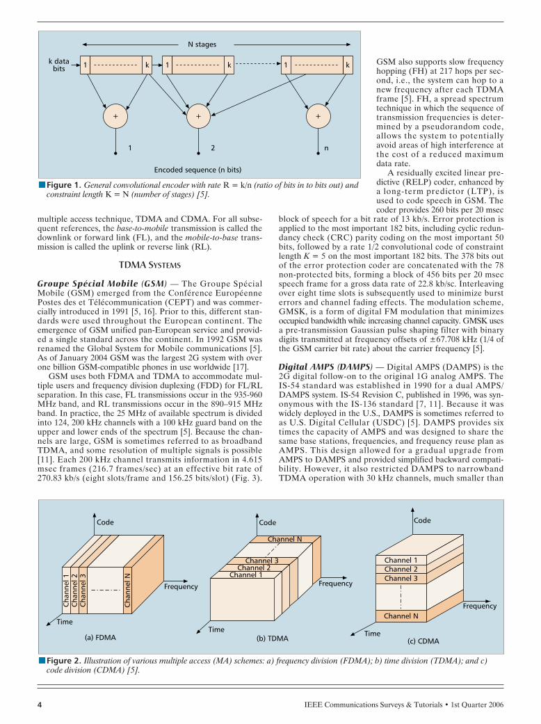
GSM uses both FDMA and TDMA to accommodate mul-tiple users and frequency division duplexing (FDD) for FL/RLseparation. In this case, FL transmissions occur in the 935-960MHz band, and RL transmissions occur in the 890–915 MHzband. In practice, the 25 MHz of available spectrum is dividedinto 124, 200 kHz channels with a 100 kHz guard band on theupper and lower ends of the spectrum [5]. Because the chan-nels are large, GSM is sometimes referred to as broadbandTDMA, and some resolution of multiple signals is possible[11]. Each 200 kHz channel transmits information in 4.615msec frames (216.7 frames/sec) at an effective bit rate of270.83 kb/s (eight slots/frame and 156.25 bits/slot) (Fig. 3).
GSM also supports slow frequencyhopping (FH) at 217 hops per sec-ond, i.e., the system can hop to anew frequency after each TDMAframe [5]. FH, a spread spectrumtechnique in which the sequence oftransmission frequencies is deter-mined by a pseudorandom code,allows the system to potentiallyavoid areas of high interference atthe cost of a reduced maximumdata rate.
A residually excited linear pre-dictive (RELP) coder, enhanced bya long-term predictor (LTP), isused to code speech in GSM. Thecoder provides 260 bits per 20 msec
block of speech for a bit rate of 13 kb/s. Error protection isapplied to the most important 182 bits, including cyclic redun-dancy check (CRC) parity coding on the most important 50bits, followed by a rate 1/2 convolutional code of constraintlength K = 5 on the most important 182 bits. The 378 bits outof the error protection coder are concatenated with the 78non-protected bits, forming a block of 456 bits per 20 msecspeech frame for a gross data rate of 22.8 kb/sc. Interleavingover eight time slots is subsequently used to minimize bursterrors and channel fading effects. The modulation scheme,GMSK, is a form of digital FM modulation that minimizesoccupied bandwidth while increasing channel capacity. GMSK usesa pre-transmission Gaussian pulse shaping filter with binarydigits transmitted at frequency offsets of ±67.708 kHz (1/4 ofthe GSM carrier bit rate) about the carrier frequency [5].
Digital AMPS (DAMPS) — Digital AMPS (DAMPS) is the2G digital follow-on to the original 1G analog AMPS. The IS-54 standard was established in 1990 for a dual AMPS/DAMPS system. IS-54 Revision C, published in 1996, was syn-onymous with the IS-136 standard [7, 11]. Because it waswidely deployed in the U.S., DAMPS is sometimes referred toas U.S. Digital Cellular (USDC) [5]. DAMPS provides sixtimes the capacity of AMPS and was designed to share thesame base stations, frequencies, and frequency reuse plan asAMPS. This design allowed for a gradual upgrade fromAMPS to DAMPS and provided simplified backward compati-bility. However, it also restricted DAMPS to narrowbandTDMA operation with 30 kHz channels, much smaller than
nFigure 2. Illustration of various multiple access (MA) schemes: a) frequency division (FDMA); b) time division (TDMA); and c)code division (CDMA) [5].
Frequency
Time
Code
(c) CDMA(b) TDMA
Channel N
Code
Frequency
Channel 3Channel 2
Channel 1
Time
Frequency
Code
(a) FDMA
Cha
nnel
1C
hann
el 2
Cha
nnel
3
Cha
nnel
N
Time
Channel N
Channel 3Channel 2Channel 1
nFigure 1. General convolutional encoder with rate R = k/n (ratio of bits in to bits out) andconstraint length K = N (number of stages) [5].
N stages
k databits 1 k
1
+
2
+
n
+
1 k 1 k
Encoded sequence (n bits)
IEEE Communications Surveys & Tutorials • 1st Quarter 2006 5
GSM. Hence, multiple signals can-not be resolved in a DAMPS sys-tem [11].
DAMPS uses both TDMA andFDMA with FDD for multipleaccess and FL/RL separation.Specifically, it divides the 25 MHzspectrum into 30 kHz channels,which are time divided into six slotsto support three full-rate users orsix half-rate users. IS-54 uses thesame 10 kb/s FSK modulation asAMPS for FL and RL control chan-nels. However, voice traffic chan-nels use differentially encodedQPSK modulation at a channel rateof 48.6 kb/s. IS-136 upgraded thecontrol channels so they also use 4-ary modulation versus FSK [5].
Each DAMPS frame is 40 msec(25 frames/sec) and contains 324bits within each 6.67 msec slot foran effective bit rate of 48.6 kb/s.Speech is encoded using the vectorsum excited linear predictive(VSELP) coder that yields a speechframe containing 159 bits every 20msec for a bit rate of 7.95 kb/s. The 77 most important speechbits are error protected using a rate 1/2 convolutional codewith constraint length K = 6. Additionally, the 12 most signifi-cant bits are further protected using a 7-bit CRC block code,yielding a gross bit rate after speech and channel coding of 13kb/s. The resultant 260 coded speech bits are interleaved overtwo successive time slots to protect against burst errors andchannel fading. DAMPS uses a spectrally-efficient, pulse-shaped, 4-phase modulation scheme, π/4 differential QPSK(DQPSK). Pulse shaping with a square-root raised cosine fil-ter minimizes intersymbol interference (ISI) [5].
Pacific Digital Cellular (PDC) — Another large 2G system isPacific Digital Cellular (PDC), also known as Japanese DigitalCellular (JDC) or Personal Digital Cellular [5]. PDC wasdeveloped in 1991 and began operation in Japan in 1993,replacing the NTT and JTACS analog systems. PDC usesTDMA with FDMA to accommodate multiple users. Thedeployment of PDC provided a much needed capacity increasein the congested 1G Japanese cellular bands. As of December2002, PDC had over 60 million subscribers but is slowly beingphased out in favor of current 3G systems [18].
PDC operation is similar to the DAMPS system describedabove, with the primary differences being channel spacing andspeech/channel coding. PDC uses 25 kHz channels (vice 30kHz) and supports a channel data rate of 42 kb/s (vice 48kb/s). Speech is encoded using a VSELP coder at 6.7 kb/s(unlike DAMPS VSELP speech coding at 7.95 kb/s). Channelcoding protects the bits using a rate 9/17 convolutional codewith constraint length K = 5. A combined 11.2 kb/s codingrate per user is provided by the joint speech and channel cod-ing [5]. Perhaps the main contribution from PDC is that itintroduced antenna diversity at the MS, which boosts systemmultiple access capability [11, 19, 20].
CDMA SYSTEMS
CDMAOne — CDMAOne, or standard IS-95A, is the only 2Gcellular system using “narrowband” CDMA technology(“wideband” CDMA is described later). IS-95A is another
large 2G system and was widely deployed by 1996. The rela-tively late deployment of IS-95A, which occurred several yearsafter other 2G systems, was primarily due to the TIA CDMAstandard not being published until 1993 [5].
Unlike other 2G systems, IS-95A allows simultaneoustransmissions in the same frequency band via CDMA (Fig. 2).CDMA is a by-product of using direct sequence spread spec-trum (DS-SS) techniques to spectrally spread the signal. DS-SS/CDMA signal discrimination is provided by assigningeach user a unique pseudorandom noise (PN) code havinglow correlation with all other PN codes. Compared to anotherspread spectrum technique, FH (as used in GSM), DS-SSallows for a higher maximum data rate (i.e., no time is wastedhopping to new frequencies), but the synchronization time islonger.
IS-95A divides the 25 MHz of FL and RL spectrum into1.25 MHz bands and uses FDD for separation. The basic datarate is 9.6 kb/s, but an extension exists that increases this to14.4 kb/s [5]. Bits at that data rate are multiplied by the PNcode with a chipping rate of 1.2288 Mchips/sec, yielding a pro-cessing gain of 128 (21 dB). Thus, the power of interferingsignals is decreased by approximately 21 dB at the receiverwhen the PN code is reapplied to despread the signal. WhileDS-SS techniques also provide low probability of interceptand anti-jam benefits, IS-95A uses DS-SS primarily for itsmultiple access benefits [21].
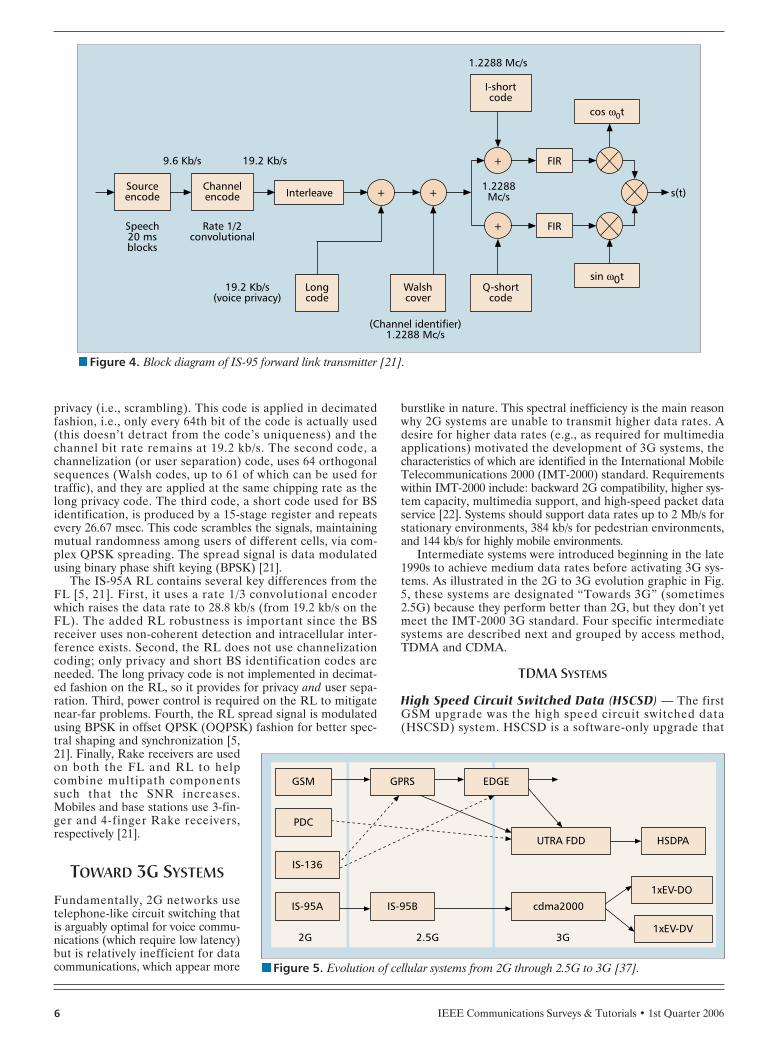
On the IS-95A FL (Fig. 4), speech signals are encodedwith a Qualcomm code excited linear predictive (QCELP)coder and processed in 20 msec frames containing 192 bits fora bit rate of 9.6 kb/s. All bits are protected (unlike GSM andDAMPS) using a rate 1/2 convolutional code with constraintlength K = 9, yielding a channel bit rate of 19.2 kb/s. Codedbits are interleaved using a 20 msec block interleaver, with384 bits interleaved every 20 msec [5, 21].
Next, three separate codes are applied to the interleaved,coded bits for privacy, channelization, and BS identification,as indicated in Fig. 4 [21]. The first code, a privacy code, is along PN code implemented via a maximal-length, 42-stageshift register, at 1.2288 Mchips/sec. Each MS is assigned atiming offset of this long code (it repeats every 41 days) for
nFigure 3. Global System for Mobile communications (GSM) TDMA/FDMA frame struc-ture [23].
935-960 MHz124 channels (200 kHz)downlink
890-915 MHz124 channels (200 KHz)uplink
GSM time-slot (normal burst)
GSM TDMA frame
4.615 ms
1 2
Tail S S Tail Guardspace
Guardspace User data Training User data
3 bits 1 1 357 bits 26 bits 57 bits
3 4 5 6 7 8
Time
Frequ
ency
Higher GSM frame structures
546.5 µs
IEEE Communications Surveys & Tutorials • 1st Quarter 20066
privacy (i.e., scrambling). This code is applied in decimatedfashion, i.e., only every 64th bit of the code is actually used(this doesn’t detract from the code’s uniqueness) and thechannel bit rate remains at 19.2 kb/s. The second code, achannelization (or user separation) code, uses 64 orthogonalsequences (Walsh codes, up to 61 of which can be used fortraffic), and they are applied at the same chipping rate as thelong privacy code. The third code, a short code used for BSidentification, is produced by a 15-stage register and repeatsevery 26.67 msec. This code scrambles the signals, maintainingmutual randomness among users of different cells, via com-plex QPSK spreading. The spread signal is data modulatedusing binary phase shift keying (BPSK) [21].
The IS-95A RL contains several key differences from theFL [5, 21]. First, it uses a rate 1/3 convolutional encoderwhich raises the data rate to 28.8 kb/s (from 19.2 kb/s on theFL). The added RL robustness is important since the BSreceiver uses non-coherent detection and intracellular inter-ference exists. Second, the RL does not use channelizationcoding; only privacy and short BS identification codes areneeded. The long privacy code is not implemented in decimat-ed fashion on the RL, so it provides for privacy and user sepa-ration. Third, power control is required on the RL to mitigatenear-far problems. Fourth, the RL spread signal is modulatedusing BPSK in offset QPSK (OQPSK) fashion for better spec-tral shaping and synchronization [5,21]. Finally, Rake receivers are usedon both the FL and RL to helpcombine multipath componentssuch that the SNR increases.Mobiles and base stations use 3-fin-ger and 4-finger Rake receivers,respectively [21].
TOWARD 3G SYSTEMS
Fundamentally, 2G networks usetelephone-like circuit switching thatis arguably optimal for voice commu-nications (which require low latency)but is relatively inefficient for datacommunications, which appear more
burstlike in nature. This spectral inefficiency is the main reasonwhy 2G systems are unable to transmit higher data rates. Adesire for higher data rates (e.g., as required for multimediaapplications) motivated the development of 3G systems, thecharacteristics of which are identified in the International MobileTelecommunications 2000 (IMT-2000) standard. Requirementswithin IMT-2000 include: backward 2G compatibility, higher sys-tem capacity, multimedia support, and high-speed packet dataservice [22]. Systems should support data rates up to 2 Mb/s forstationary environments, 384 kb/s for pedestrian environments,and 144 kb/s for highly mobile environments.
Intermediate systems were introduced beginning in the late1990s to achieve medium data rates before activating 3G sys-tems. As illustrated in the 2G to 3G evolution graphic in Fig.5, these systems are designated “Towards 3G” (sometimes2.5G) because they perform better than 2G, but they don’t yetmeet the IMT-2000 3G standard. Four specific intermediatesystems are described next and grouped by access method,TDMA and CDMA.
TDMA SYSTEMS
High Speed Circuit Switched Data (HSCSD) — The firstGSM upgrade was the high speed circuit switched data(HSCSD) system. HSCSD is a software-only upgrade that
nFigure 4. Block diagram of IS-95 forward link transmitter [21].
Interleave1.2288Mc/s s(t)
FIR
cos ω0t
9.6 Kb/s 19.2 Kb/s
Sourceencode
Speech20 msblocks
Channelencode
Longcode
19.2 Kb/s(voice privacy)
Rate 1/2convolutional
+ +
+
+
Walshcover
(Channel identifier)1.2288 Mc/s
Q-shortcode
I-shortcode
1.2288 Mc/s
FIR
sin ω0t
nFigure 5. Evolution of cellular systems from 2G through 2.5G to 3G [37].
EDGEGSM
PDC
IS-136
IS-95A
GPRS
IS-95B cdma2000
3G2.5G2G
UTRA FDD HSDPA
1xEV-DO
1xEV-DV
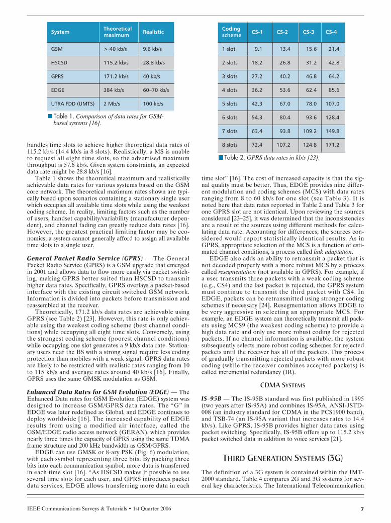
bundles time slots to achieve higher theoretical data rates of115.2 kb/s (14.4 kb/s in 8 slots). Realistically, a MS is unableto request all eight time slots, so the advertised maximumthroughput is 57.6 kb/s. Given system constraints, an expecteddata rate might be 28.8 kb/s [16].
Table 1 shows the theoretical maximum and realisticallyachievable data rates for various systems based on the GSMcore network. The theoretical maximum rates shown are typi-cally based upon scenarios containing a stationary single userwhich occupies all available time slots while using the weakestcoding scheme. In reality, limiting factors such as the numberof users, handset capability/variability (manufacturer depen-dent), and channel fading can greatly reduce data rates [16].However, the greatest practical limiting factor may be eco-nomics; a system cannot generally afford to assign all availabletime slots to a single user.
General Packet Radio Service (GPRS) — The GeneralPacket Radio Service (GPRS) is a GSM upgrade that emergedin 2001 and allows data to flow more easily via packet switch-ing, making GPRS better suited than HSCSD to transmithigher data rates. Specifically, GPRS overlays a packet-basedinterface with the existing circuit switched GSM network.Information is divided into packets before transmission andreassembled at the receiver.
Theoretically, 171.2 kb/s data rates are achievable usingGPRS (see Table 2) [23]. However, this rate is only achiev-able using the weakest coding scheme (best channel condi-tions) while occupying all eight time slots. Conversely, usingthe strongest coding scheme (poorest channel conditions)while occupying one slot generates a 9 kb/s data rate. Station-ary users near the BS with a strong signal require less codingprotection than mobiles with a weak signal. GPRS data ratesare likely to be restricted with realistic rates ranging from 10to 115 kb/s and average rates around 40 kb/s [16]. Finally,GPRS uses the same GMSK modulation as GSM.
Enhanced Data Rates for GSM Evolution (EDGE) — TheEnhanced Data rates for GSM Evolution (EDGE) system wasdesigned to increase GSM/GPRS data rates. The “G” inEDGE was later redefined as Global, and EDGE continues todeploy worldwide [16]. The increased capability of EDGEresults from using a modified air interface, called theGSM/EDGE radio access network (GERAN), which providesnearly three times the capacity of GPRS using the same TDMAframe structure and 200 kHz bandwidth as GSM/GPRS.
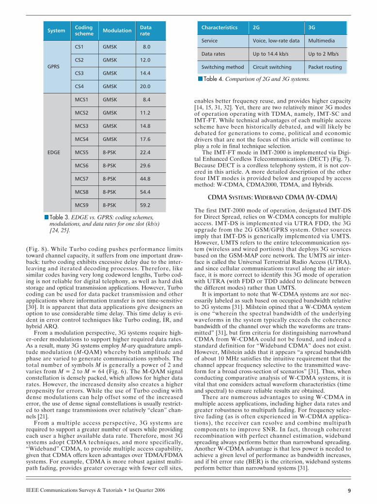
EDGE can use GMSK or 8-ary PSK (Fig. 6) modulation,with each symbol representing three bits. By packing threebits into each communication symbol, more data is transferredin each time slot [16]. “As HSCSD makes it possible to useseveral time slots for each user, and GPRS introduces packetdata services, EDGE allows transferring more data in each
time slot” [16]. The cost of increased capacity is that the sig-nal quality must be better. Thus, EDGE provides nine differ-ent modulation and coding schemes (MCS) with data ratesranging from 8 to 60 kb/s for one slot (see Table 3). It isnoted here that data rates reported in Table 2 and Table 3 forone GPRS slot are not identical. Upon reviewing the sourcesconsidered [23–25], it was determined that the inconsistenciesare a result of the sources using different methods for calcu-lating data rate. Accounting for differences, the sources con-sidered would report statistically identical results. As inGPRS, appropriate selection of the MCS is a function of esti-mated channel conditions, a process called link adaptation.
EDGE also adds an ability to retransmit a packet that isnot decoded properly with a more robust MCS by a processcalled resegmentation (not available in GPRS). For example, ifa user transmits three packets with a weak coding scheme(e.g., CS4) and the last packet is rejected, the GPRS systemmust continue to transmit the third packet with CS4. InEDGE, packets can be retransmitted using stronger codingschemes if necessary [24]. Resegmentation allows EDGE tobe very aggressive in selecting an appropriate MCS. Forexample, an EDGE system can theoretically transmit all pack-ets using MCS9 (the weakest coding scheme) to provide ahigh data rate and only use more robust coding for rejectedpackets. If no channel information is available, the systemsubsequently selects more robust coding schemes for rejectedpackets until the receiver has all of the packets. This processof gradually transmitting rejected packets with more robustcoding (while the receiver combines accepted packets) iscalled incremental redundancy (IR).
CDMA SYSTEMS
IS-95B — The IS-95B standard was first published in 1995(two years after IS-95A) and combines IS-95A, ANSI-JSTD-008 (an industry standard for CDMA in the PCS1900 band),and TSB-74 (an IS-95A variant that increases rates to 14.4kb/s). Like GPRS, IS-95B provides higher data rates usingpacket switching. Specifically, IS-95B offers up to 115.2 kb/spacket switched data in addition to voice services [21].
THIRD GENERATION SYSTEMS (3G)The definition of a 3G system is contained within the IMT-2000 standard. Table 4 compares 2G and 3G systems for sev-eral key characteristics. The International Telecommunication
IEEE Communications Surveys & Tutorials • 1st Quarter 2006 7
nTable 1. Comparison of data rates for GSM-based systems [16].
System Theoreticalmaximum Realistic
GSM > 40 kb/s 9.6 kb/s
HSCSD 115.2 kb/s 28.8 kb/s
GPRS 171.2 kb/s 40 kb/s
EDGE 384 kb/s 60–70 kb/s
UTRA FDD (UMTS) 2 Mb/s 100 kb/s
nTable 2. GPRS data rates in kb/s [23].
Codingscheme CS-1 CS-2 CS-3 CS-4
1 slot 9.1 13.4 15.6 21.4
2 slots 18.2 26.8 31.2 42.8
3 slots 27.2 40.2 46.8 64.2
4 slots 36.2 53.6 62.4 85.6
5 slots 42.3 67.0 78.0 107.0
6 slots 54.3 80.4 93.6 128.4
7 slots 63.4 93.8 109.2 149.8
8 slots 72.4 107.2 124.8 171.2
IEEE Communications Surveys & Tutorials • 1st Quarter 20068
Union — Radiocommunication (ITU-R) sector created theIMT-2000 standard with the original intent to unify all wire-less systems (cellular, wireless local area networks (WLANs),satellite networks, and fixed wireless links) in the same fre-quency bands and on ATM-based protocols (under theFPLMTS acronym for Future Public Land Mobile Telecom-munications Systems) [5]. The fixed and WLAN componentswere soon discarded from the IMT-2000 vision since fixedwireless operates better on higher frequencies, and WLANscan achieve higher data rates in unlicensed bands. Hence, theIMT-2000 standard has cellular and satellite components. Thesatellite component, also called mobile satellite service (MSS),is designed to provide communication services when a user isoutside the range of any land-based BS [26]. Further refer-ences herein to IMT-2000 refer to the cellular component ofthe standard.
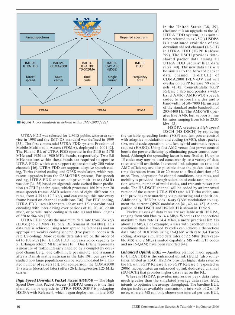
In June 1996 the ITU-R invited proposals for cellular andsatellite 3G concepts [22]. Although the original goal was tohave a single worldwide cellular standard, down-selection to asingle mode of operation for IMT-2000 proved difficult. Inthe summer of 1998, the ITU-R received 15 proposals for 3Gsystem operation. In 2000 the final IMT-2000 recommenda-tion ITU-R M.1457 featured five modes of operation: DirectSpread (IMT-DS), Multi-Carrier (IMT-MC), Time Code(IMT-TC), Single Carrier (IMT-SC), and Frequency Time(IMT-FT) [22, 27]. Of the five modes, three use CDMA(DS/MC/TC), three use TDMA (TC/SC/FT), one uses FDMA(FT), three use paired spectrum (DS/MC/SC), and two useunpaired spectrum (TC/FT) (Fig. 7). Paired/unpaired spec-
trum implies that FDD or time division duplexing (TDD) isused for FL and RL separation, respectively.
The pursuit of 3G technologies and the process of down-selecting IMT-2000 candidate concepts spawned two majororganizations (or partnerships) to manage the standards ofthe two main competing concepts: W-CDMA (IMT-DS) andCDMA2000 (IMT-MC) [13]. The Third Generation Partner-ship Project (3GPP) manages the Universal Mobile Telecom-munication System (UMTS) specifications that applyW-CDMA concepts and build upon the GSM-MAP core net-work. The 3GPP2 organization manages the CDMA2000specifications that build upon the ANSI/TIA/EIA-41 core net-work. These bodies unite regional standards organizations tosubmit unified proposals to the ITU and standardize systemdevelopments. In fact, 3GPP and 3GPP2 meet regularly toincrease harmonization between the two main 3G concepts.
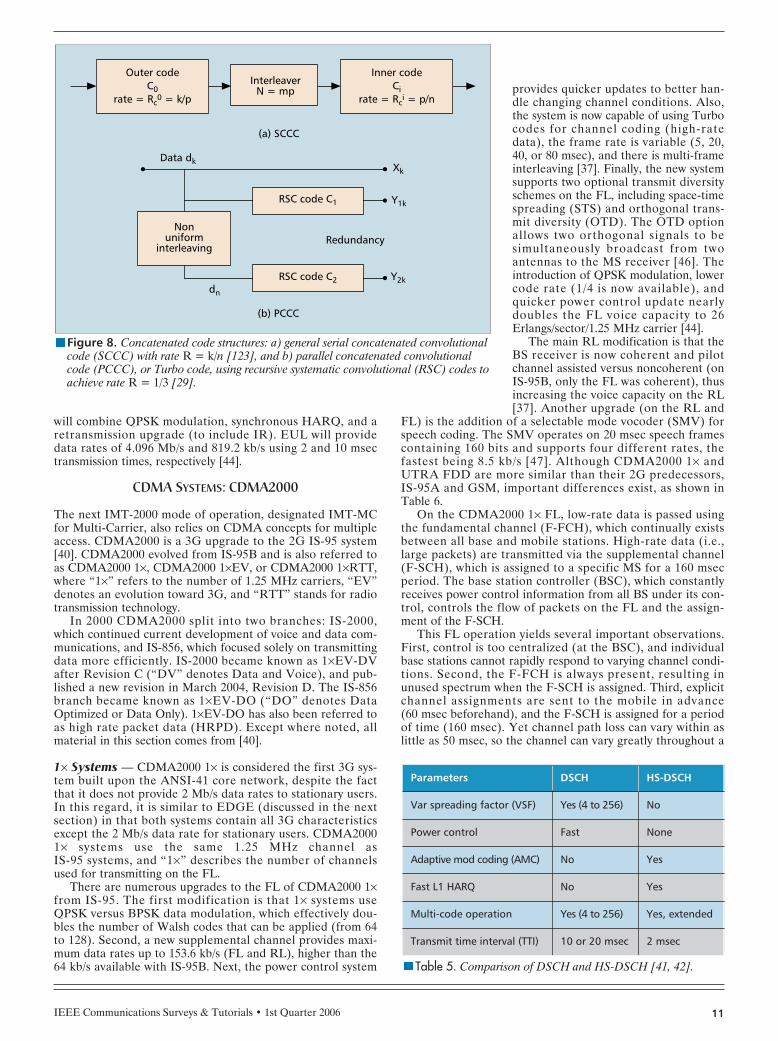
One of the biggest drivers for 3G development was theneed for multimedia-level data rates. From a coding perspec-tive, 3G systems required a coding capability that pushed per-formance closer to the Shannon limit than what was previouslyachieved with block and convolutional codes. Hence, many 3Gsystems quickly adopted Turbo coding [28–30], which signifi-cantly closed the gap on the Shannon limit (e.g., performancewithin 0.5 dB of the Shannon limit has been demonstrated atPb = 10–5). The Turbo coding research of Berrou andGlavieux [28, 29] was based on applying feedback techniquesto coding in digital receivers [30]. Turbo codes are generatedusing a parallel organization of two recursive systematic con-volutional (RSC) codes interconnected with an interleaver
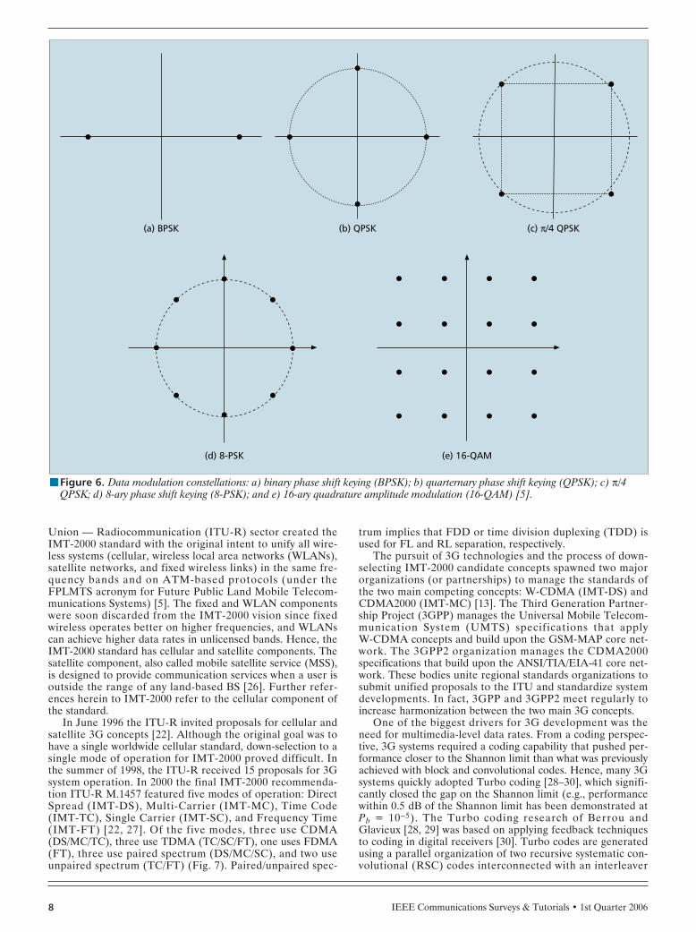
nFigure 6. Data modulation constellations: a) binary phase shift keying (BPSK); b) quarternary phase shift keying (QPSK); c) π/4QPSK; d) 8-ary phase shift keying (8-PSK); and e) 16-ary quadrature amplitude modulation (16-QAM) [5].
(a) BPSK (b) QPSK (c) π/4 QPSK
(d) 8-PSK (e) 16-QAM
(Fig. 8). While Turbo coding pushes performance limitstoward channel capacity, it suffers from one important draw-back: turbo coding exhibits excessive delay due to the inter-leaving and iterated decoding processes. Therefore, likesimilar codes having very long codeword lengths, Turbo cod-ing is not reliable for digital telephony, as well as hard diskstorage and optical transmission applications. However, Turbocoding can be used for data packet transmission and otherapplications where information transfer is not time-sensitive[30]. It is apparent that data applications give designers anoption to use considerable time delay. This time delay is evi-dent in error control techniques like Turbo coding, IR, andhybrid ARQ.
From a modulation perspective, 3G systems require high-er-order modulations to support higher required data rates.As a result, many 3G systems employ M-ary quadrature ampli-tude modulation (M-QAM) whereby both amplitude andphase are varied to generate communications symbols. Thetotal number of symbols M is generally a power of 2 andvaries from M = 2 to M = 64 (Fig. 6). The M-QAM signalconstellation is densely packed, which allows for higher datarates. However, the increased density also creates a higherpropensity for errors. While the use of Turbo coding withdense modulations can help offset some of the increasederror, the use of dense signal constellations is usually restrict-ed to short range transmissions over relatively “clean” chan-nels [21].
From a multiple access perspective, 3G systems arerequired to support a greater number of users while providingeach user a higher available data rate. Therefore, most 3Gsystems adopt CDMA techniques, and more specifically,“Wideband” CDMA, to provide multiple access capability,given that CDMA offers keen advantages over TDMA/FDMAsystems. For example, CDMA is more robust against multi-path fading, provides greater coverage with fewer cell sites,
enables better frequency reuse, and provides higher capacity[14, 15, 31, 32]. Yet, there are two relatively minor 3G modesof operation operating with TDMA, namely, IMT-SC andIMT-FT. While technical advantages of each multiple accessscheme have been historically debated, and will likely bedebated for generations to come, political and economicdrivers that are not the focus of this article will continue toplay a role in final technique selection.
The IMT-FT mode in IMT-2000 is implemented via Digi-tal Enhanced Cordless Telecommunications (DECT) (Fig. 7).Because DECT is a cordless telephony system, it is not cov-ered in this article. A more detailed description of the otherfour IMT modes is provided below and grouped by accessmethod: W-CDMA, CDMA2000, TDMA, and Hybrids.
CDMA SYSTEMS: WIDEBAND CDMA (W-CDMA)
The first IMT-2000 mode of operation, designated IMT-DSfor Direct Spread, relies on W-CDMA concepts for multipleaccess. IMT-DS is implemented via UTRA FDD, the 3Gupgrade from the 2G GSM/GPRS system. Other sourcesimply that IMT-DS is generically implemented via UMTS.However, UMTS refers to the entire telecommunication sys-tem (wireless and wired portions) that deploys 3G servicesbased on the GSM-MAP core network. The UMTS air inter-face is called the Universal Terrestrial Radio Access (UTRA),and since cellular communications travel along the air inter-face, it is more correct to identify this 3G mode of operationwith UTRA (with FDD or TDD added to delineate betweenthe different modes) rather than UMTS.
It is important to note that W-CDMA systems are not nec-essarily labeled as such based on occupied bandwidth relativeto 2G systems [31]. Milstein opined that a W-CDMA systemis one “wherein the spectral bandwidth of the underlyingwaveforms in the system typically exceeds the coherencebandwidth of the channel over which the waveforms are trans-mitted” [31], but firm criteria for distinguishing narrowbandCDMA from W-CDMA could not be found, and indeed astandard definition for “Wideband CDMA” does not exist.However, Milstein adds that it appears “a spread bandwidthof about 10 MHz satisfies the intuitive requirement that thechannel appear frequency selective to the transmitted wave-form for a broad cross-section of scenarios” [31]. Thus, whenconducting comparative analysis of W-CDMA systems, it isvital that one considers actual waveform characteristics (timeand spectral) to ensure reliable results are obtained.
There are numerous advantages to using W-CDMA inmultiple access applications, including higher data rates andgreater robustness to multipath fading. For frequency selec-tive fading (as is often experienced in W-CDMA applica-tions), the receiver can resolve and combine multipathcomponents to improve SNR. In fact, through coherentrecombination with perfect channel estimation, widebandspreading always performs better than narrowband spreading.Another W-CDMA advantage is that less power is needed toachieve a given level of performance as bandwidth increases,and if bit error rate (BER) is the criterion, wideband systemsperform better than narrowband systems [31].
IEEE Communications Surveys & Tutorials • 1st Quarter 2006 9
nTable 3. EDGE vs. GPRS: coding schemes,modulations, and data rates for one slot (kb/s)[24, 25].
System Codingscheme Modulation Data
rate
GPRS
CS1 GMSK 8.0
CS2 GMSK 12.0
CS3 GMSK 14.4
CS4 GMSK 20.0
EDGE
MCS1 GMSK 8.4
MCS2 GMSK 11.2
MCS3 GMSK 14.8
MCS4 GMSK 17.6
MCS5 8-PSK 22.4
MCS6 8-PSK 29.6
MCS7 8-PSK 44.8
MCS8 8-PSK 54.4
MCS9 8-PSK 59.2
nTable 4. Comparison of 2G and 3G systems.
Characteristics 2G 3G
Service Voice, low-rate data Multimedia
Data rates Up to 14.4 kb/s Up to 2 Mb/s
Switching method Circuit switching Packet routing
IEEE Communications Surveys & Tutorials • 1st Quarter 200610
UTRA FDD was selected for UMTS public, wide-area ser-vice in 1998 and the IMT-DS standard was defined in 1999[33]. The first commercial UTRA FDD system, Freedom ofMobile Multimedia Access (FOMA), deployed in 2001 [2].The FL and RL of UTRA FDD operate in the 2110 to 2170MHz and 1920 to 1980 MHz bands, respectively. Two 5.0MHz sections within these bands are required to operateUTRA FDD, which can support approximately 200 voicechannels [16]. UTRA FDD can support adaptive speech cod-ing, Turbo channel coding, and QPSK modulation, which rep-resent upgrades from the GSM/GPRS systems. For speechcoding, UTRA FDD uses an adaptive multi-rate (AMR)vocoder [34, 35] based on algebraic code excited linear predic-tion (ACELP) techniques, which processes 160 bits per 20msec speech frame. AMR selects one of eight different bitrates, from 4.75 to 12.2 kb/s, and can change this rate everyframe based on channel conditions [36]. For FEC coding,UTRA FDD uses either rate 1/2 or rate 1/3 convolutionalencoding with interleaving over periods of 10, 20, 40, or 80msec, or parallel turbo coding with rate 1/3 and block lengthsof 320 to 564 bits [37].
UTRA FDD boosts the maximum data rate from 384 kb/s(EDGE) to 2.3 Mb/s (FL only, RL remains at 384 kb/s). Thisdata rate is achieved using a low spreading factor (4) and anappropriate weaker coding scheme (five parallel codes withrate 1/2 coding). More realistic data rates are on the order of64 to 100 kb/s [16]. UTRA FDD increases voice capacity to 51 Erlangs/sector/5 MHz carrier [16]. (One Erlang representsa measure of traffic intensity handled by a completely occu-pied channel, e.g., one call-minute per minute, and is namedafter a Danish mathematician in the late 19th century whostudied how large populations can be accommodated by a lim-ited number of servers [5]). For comparison, the CDMA20001× system (described later) offers 26 Erlangs/sector/1.25 MHzcarrier.
High Speed Downlink Packet Access (HSDPA) — The HighSpeed Downlink Packet Access (HSDPA) concept is the firstplanned major upgrade to UTRA FDD. 3GPP is packagingHSDPA with Release 5, which began deployment in late 2005
in the United States [38, 39].(Because it is an upgrade to the 3GUTRA FDD system, it is some-times referred to as 3.5G.) HSDPAis a continued evolution of thedownlink shared channel (DSCH)in UTRA FDD (3GPP Release’99). The DSCH provides time-shared packet data among allUTRA FDD users at high datarates [40]. The new data link willbe similar to the forward packetdata channel (F-PDCH) ofCDMA2000 1×EV-DV and willoverlay on 3GPP Release ’99 chan-nels [41, 42]. Coincidentally, 3GPPRelease 5 also incorporates a wide-band AMR (AMR-WB) speechcodec to support a wider audiobandwidth of 50–7000 Hz insteadof the standard audio bandwidth of200–3400 Hz. The AMR-WB oper-ates like AMR but supports ninebit rates ranging from 6.6 to 23.85kb/s [43].
HSDPA creates a high-speedDSCH (HS-DSCH) by replacing
the variable spreading factor (VSF) and fast power controlwith adaptive modulation and coding (AMC), short packetsize, multi-code operation, and fast hybrid automatic repeatrequest (HARQ). Using fast AMC versus fast power controlboosts the power efficiency by eliminating power control over-head. Although the spreading factor is now fixed at 16, up to15 codes may now be used concurrently, so a variety of datarates are still available. Increased link adaptation rate andAMC efficiency are also possible since the packet durationtime decreases from 10 or 20 msec to a fixed duration of 2msec. Thus, adaptation for channel conditions, data rates, andmobility is provided through selection of code rate, modula-tion scheme, number of multi-codes, and transmit power percode. The HS-DSCH channel will be coded by an improvedversion of the current UTRA FDD rate 1/3 Turbo coder, onethat provides rate matching via puncturing and repetition.Additionally, HSDPA adds 16-ary QAM modulation to aug-ment the current QPSK modulation [41, 42, 44, 45]. A com-parison of the DSCH and HS-DSCH is shown in Table 5.
Twelve classes of data rates are available with HSDPA,ranging from 900 kb/s to 14.4 Mb/s. Whereas the theoreticalmaximum data rate is 14.4 Mb/s, a more practical limit isabout 10 Mb/s. For example, a user with excellent channelconditions that is afforded 15 codes can achieve a theoreticaldata rate of 10.8 Mb/s using 16-QAM with rate 3/4 Turbocoding. Average simulated data rates of 2.5 Mb/s (fully capa-ble MS) and 2 Mb/s (limited capability MS with 5/15 codesand no 16-QAM) have been reported [44].
Enhanced Uplink (EUL) — Another planned major upgradeto UTRA FDD is the enhanced uplink (EUL) (also some-times labeled as 3.5G). HSDPA provides higher data rates onthe FL with 3GPP Release 5, so 3GPP Release 6 (expected in2006) incorporates an enhanced uplink dedicated channel(EU-DCH) that provides higher data rates on the RL.
Whereas HSDPA provides impressive peak data ratesmuch greater than the simulated average data rates, EULintends to optimize the average throughput. The baseline EULdesign includes available transmission intervals of 2 or 10msec, where a MS can only choose one interval per use. EUL
nFigure 7. 3G standards as defined within IMT-2000 [122].
CDMA TDMA FDMA
IMT-DSUTRA FDD
Directspread
IMT-SCUWC-136
(EDGE)
Singlecarrier
IMT-FTDECT
Frequencytime
IMT-MCCDMA2000
Multicarrier
IMT-TCUTRA TDDTD-SCDMA
Timecode
Paired spectrum Unpaired spectrum
IEEE Communications Surveys & Tutorials • 1st Quarter 2006 11
will combine QPSK modulation, synchronous HARQ, and aretransmission upgrade (to include IR). EUL will providedata rates of 4.096 Mb/s and 819.2 kb/s using 2 and 10 msectransmission times, respectively [44].
CDMA SYSTEMS: CDMA2000
The next IMT-2000 mode of operation, designated IMT-MCfor Multi-Carrier, also relies on CDMA concepts for multipleaccess. CDMA2000 is a 3G upgrade to the 2G IS-95 system[40]. CDMA2000 evolved from IS-95B and is also referred toas CDMA2000 1×, CDMA2000 1×EV, or CDMA2000 1×RTT,where “1×” refers to the number of 1.25 MHz carriers, “EV”denotes an evolution toward 3G, and “RTT” stands for radiotransmission technology.
In 2000 CDMA2000 split into two branches: IS-2000,which continued current development of voice and data com-munications, and IS-856, which focused solely on transmittingdata more efficiently. IS-2000 became known as 1×EV-DVafter Revision C (“DV” denotes Data and Voice), and pub-lished a new revision in March 2004, Revision D. The IS-856branch became known as 1×EV-DO (“DO” denotes DataOptimized or Data Only). 1×EV-DO has also been referred toas high rate packet data (HRPD). Except where noted, allmaterial in this section comes from [40].
1× Systems — CDMA2000 1× is considered the first 3G sys-tem built upon the ANSI-41 core network, despite the factthat it does not provide 2 Mb/s data rates to stationary users.In this regard, it is similar to EDGE (discussed in the nextsection) in that both systems contain all 3G characteristicsexcept the 2 Mb/s data rate for stationary users. CDMA20001× systems use the same 1.25 MHz channel as IS-95 systems, and “1×” describes the number of channelsused for transmitting on the FL.
There are numerous upgrades to the FL of CDMA2000 1×from IS-95. The first modification is that 1× systems useQPSK versus BPSK data modulation, which effectively dou-bles the number of Walsh codes that can be applied (from 64to 128). Second, a new supplemental channel provides maxi-mum data rates up to 153.6 kb/s (FL and RL), higher than the64 kb/s available with IS-95B. Next, the power control system
provides quicker updates to better han-dle changing channel conditions. Also,the system is now capable of using Turbocodes for channel coding (high-ratedata), the frame rate is variable (5, 20,40, or 80 msec), and there is multi-frameinterleaving [37]. Finally, the new systemsupports two optional transmit diversityschemes on the FL, including space-timespreading (STS) and orthogonal trans-mit diversity (OTD). The OTD optionallows two orthogonal signals to besimultaneously broadcast from twoantennas to the MS receiver [46]. Theintroduction of QPSK modulation, lowercode rate (1/4 is now available), andquicker power control update nearlydoubles the FL voice capacity to 26Erlangs/sector/1.25 MHz carrier [44].
The main RL modification is that theBS receiver is now coherent and pilotchannel assisted versus noncoherent (onIS-95B, only the FL was coherent), thusincreasing the voice capacity on the RL[37]. Another upgrade (on the RL and
FL) is the addition of a selectable mode vocoder (SMV) forspeech coding. The SMV operates on 20 msec speech framescontaining 160 bits and supports four different rates, thefastest being 8.5 kb/s [47]. Although CDMA2000 1× andUTRA FDD are more similar than their 2G predecessors, IS-95A and GSM, important differences exist, as shown inTable 6.
On the CDMA2000 1× FL, low-rate data is passed usingthe fundamental channel (F-FCH), which continually existsbetween all base and mobile stations. High-rate data (i.e.,large packets) are transmitted via the supplemental channel(F-SCH), which is assigned to a specific MS for a 160 msecperiod. The base station controller (BSC), which constantlyreceives power control information from all BS under its con-trol, controls the flow of packets on the FL and the assign-ment of the F-SCH.
This FL operation yields several important observations.First, control is too centralized (at the BSC), and individualbase stations cannot rapidly respond to varying channel condi-tions. Second, the F-FCH is always present, resulting inunused spectrum when the F-SCH is assigned. Third, explicitchannel assignments are sent to the mobile in advance (60 msec beforehand), and the F-SCH is assigned for a periodof time (160 msec). Yet channel path loss can vary within aslittle as 50 msec, so the channel can vary greatly throughout a
nFigure 8. Concatenated code structures: a) general serial concatenated convolutionalcode (SCCC) with rate R = k/n [123], and b) parallel concatenated convolutionalcode (PCCC), or Turbo code, using recursive systematic convolutional (RSC) codes toachieve rate R = 1/3 [29].
RedundancyNon
uniforminterleaving
Data dkXk
(a) SCCC
(b) PCCC
InterleaverN = mp
Outer codeC0
rate = Rc0 = k/p
Inner codeCi
rate = Rci = p/n
dn
RSC code C1
Y2k
Y1k
RSC code C2
nTable 5. Comparison of DSCH and HS-DSCH [41, 42].
Parameters DSCH HS-DSCH
Var spreading factor (VSF) Yes (4 to 256) No
Power control Fast None
Adaptive mod coding (AMC) No Yes
Fast L1 HARQ No Yes
Multi-code operation Yes (4 to 256) Yes, extended
Transmit time interval (TTI) 10 or 20 msec 2 msec
large packet transmission. Finally, transmissions are powercontrolled throughout the process, resulting in excess powerbeing transmitted.
1× EV-DO — In 2000 a branch emerged from the CDMA20001× standard called IS-856, now commonly termed 1×EV-DO.1×EV-DO introduces a separate carrier just for data, provid-ing data rates up to 3.1 Mb/s on the FL and 1.8 Mb/s on theRL.
A key enabler to higher data rates in 1×EV-DO is theHARQ protocol (also used in UTRA FDD). CDMA2000 1×uses the radio link protocol (RLP) at the link layer to decidewhen packets must be retransmitted. HARQ replicates RLPprocesses at the physical layer for 1×EV-DO. To use theHARQ protocol, each physical layer data packet is encodedinto subpackets. The transmitter continues to send subpacketsuntil notified otherwise. The identity of the subpackets isknown at the receiver, and it combines subpackets for betterdecoding. Subpackets are accumulated at the receiver untilthe required SNR is met. The advantage of HARQ is that thetransmitter only sends subpackets until the required minimumSNR is achieved, resulting in less wasted transmitted powerand less interference to other users [48].
The 1×EV-DO FL operation is unlike the FL ofCDMA2000 1×. Each MS relays its requested rate on the datarate control (DRC) channel and best sector ID on the datasector control (DSC) channel. The BS then selects the appro-priate recipient and format for transmission. FL transmissionscontain a preamble identifying the destination MS. Upondetecting its preamble, the MS combines and decodes thedata and notifies the BS. The BS then decides whether itshould send more subpackets.
To transmit to distant dynamic mobiles, base stations uselonger preambles (up to 1024 chips) with payload sizes of 128to 1024 bits distributed over 16 slots using QPSK modulation.If the mobile is nearer the BS and/or more stationary, thepreamble size is reduced (as low as 64 chips) with payloadsizes up to 5,120 bits distributed over one slot using 16-QAM.Each 1.67 msec FL slot contains 2,048 chips, of which 1,600
are for data and 448 are for medium access con-trol (MAC) and pilot signals.
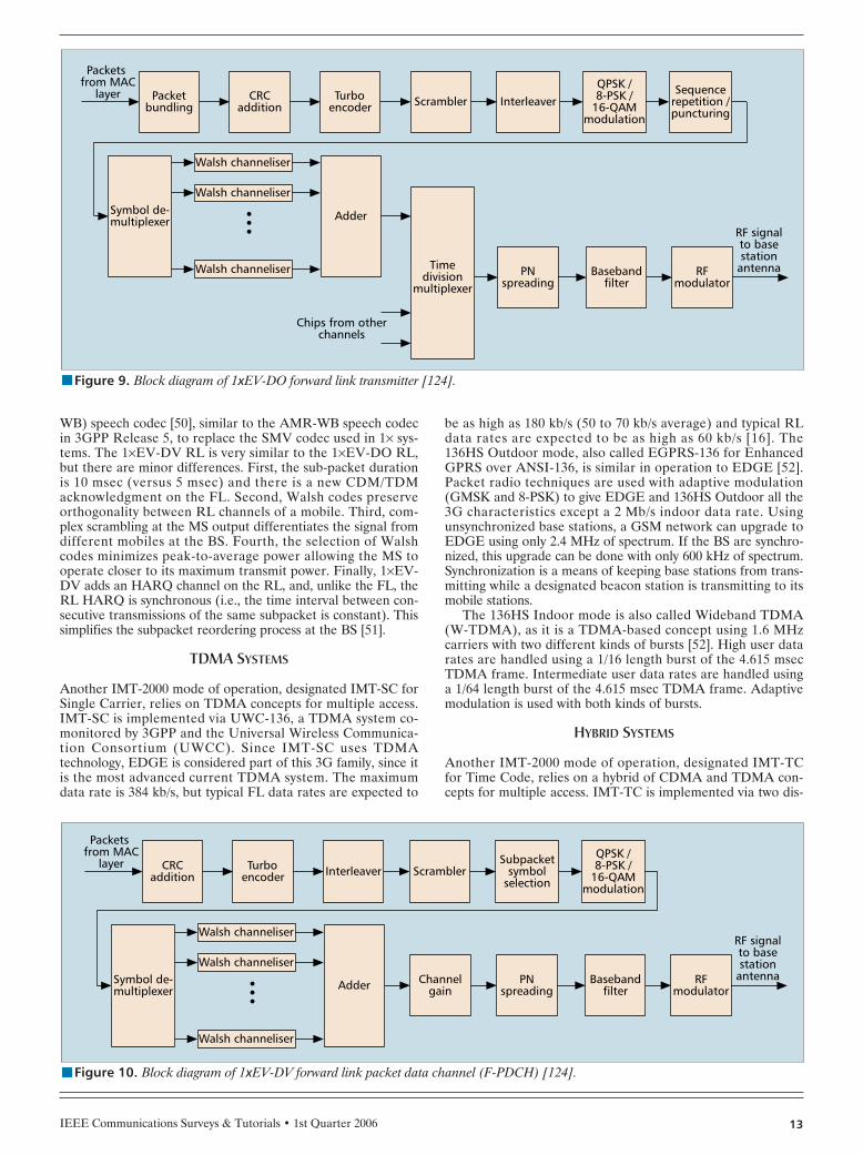
Another change is that the BS on the 1×EV-DO FL (Fig. 9) only transmits to one user at atime. In that respect, the FL is more TDMA-like(CDMA is only used for spreading), resulting invery short transmissions, during which the propa-gation channel changes very little. (In general,the TDM scheme allows the BS to transmit maxi-mum power all the time to each single user. How-ever, multi-user TDM packets may also beconstructed and transmitted within a time slot,with each MS identifying its packets using speci-fied MAC indices.) The FL uses shorter inter-leaving times, and it eliminates power control.Since mobiles report the requested rate via theDRC, a power control loop is not needed.Because there is an established data link, there isno longer any reason to request an advance chan-nel assignment (as with F-SCH), and the BStransmits one subpacket at a time.
There are some key differences in 1×EV-DORL and FL operation. First, subpacket durationsof 5 msec (RL) and 1.67 msec (FL) are used. Thelonger RL duration is needed because the MSpower amplifier is smaller than the BS amplifier.Second, the FL only sends control informationwith the first subpacket. However, given low cost
memory and available space, the BS buffers everythingreceived from the MS and thus, all subpackets include controlinformation. Third, BPSK (for low rates using one Walshchannel), QPSK (for medium rates using one or two Walshchannels), and 8-PSK (for high rates using two Walsh chan-nels) modulations are employed on the RL, depending onrequired data rate. The FL employs QPSK, 8-PSK, and 16-QAM modulations. Twelve payload sizes offer data ratesfrom 4.8 kb/s to 1.8 Mb/s, and all payload sizes may use up tofour subpackets. Fourth, while the FL is migrating towardTDM-like operation, the RL remains very dependent onCDM, using Walsh codes like IS-95A/B and CDMA2000 1×.Fifth, the RL remains power controlled (at 400 Hz) to addressthe near-far problem.
1× EV-DV — After CDMA2000 1× Revision C was published,the IS-2000 standard was renamed 1×EV-DV (and sometimeslabeled as 3.5G). 1×EV-DV combines the data performance of1×EV-DO (3.1 Mb/s on FL) with traditional voice services on asingle new channel called the forward packet data channel (F-PDCH). F-PDCH is a high-rate channel that is rapidly time-shared among users and employs dynamic modulation andcoding based on channel conditions. A major principle in the1×EV-DV FL design is that modulation and coding are rapidlyadapted for each subpacket, with adapted parameters based onavailable BS resources (e.g., number of Walsh codes and avail-able power), the amount of data to transmit, and channel con-ditions — a small step toward cognitive radio. This adaptationallows for full use of spectrum resources. Revision D was pub-lished in 2004 and introduces a new high-speed packet datachannel for RL data (1.8 Mb/s) and voice transfer [49].
The 1×EV-DV FL effectively pools all remaining Walshcodes and power into the F-PDCH channel (Fig. 10). It inte-grates HARQ, short frames, rate adaptation, no advance signal-ing, and no power control on the FPDCH. Meanwhile, alllegacy channels from CDMA2000 1× can cohabit with the F-PDCH. Since each MS reports its interference level, the BS candecide what format to transmit. Finally, 1×EV-DV will likelyincorporate a new variable-rate multimode wideband (VMR-
IEEE Communications Surveys & Tutorials • 1st Quarter 200612
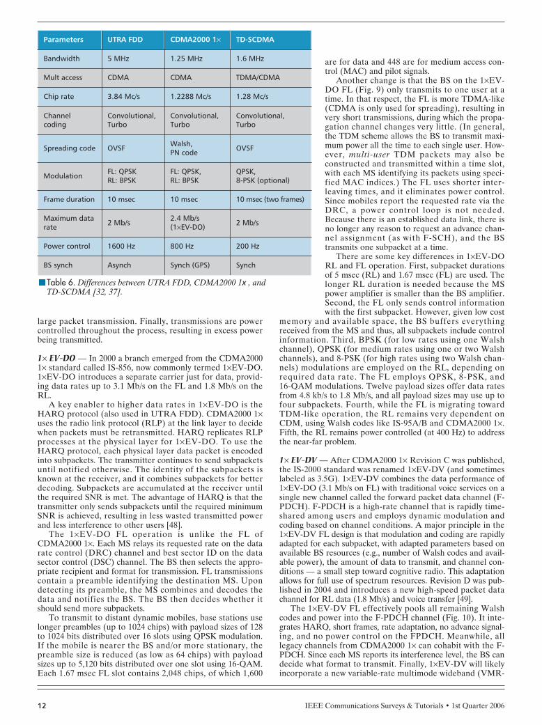
nTable 6. Differences between UTRA FDD, CDMA2000 1x , and TD-SCDMA [32, 37].
Parameters UTRA FDD CDMA2000 1× TD-SCDMA
Bandwidth 5 MHz 1.25 MHz 1.6 MHz
Mult access CDMA CDMA TDMA/CDMA
Chip rate 3.84 Mc/s 1.2288 Mc/s 1.28 Mc/s
Channelcoding
Convolutional,Turbo
Convolutional,Turbo
Convolutional,Turbo
Spreading code OVSF Walsh,PN code OVSF
Modulation FL: QPSKRL: BPSK
FL: QPSK,RL: BPSK
QPSK,8-PSK (optional)
Frame duration 10 msec 10 msec 10 msec (two frames)
Maximum datarate 2 Mb/s
2.4 Mb/s(1×EV-DO) 2 Mb/s
Power control 1600 Hz 800 Hz 200 Hz
BS synch Asynch Synch (GPS) Synch
WB) speech codec [50], similar to the AMR-WB speech codecin 3GPP Release 5, to replace the SMV codec used in 1× sys-tems. The 1×EV-DV RL is very similar to the 1×EV-DO RL,but there are minor differences. First, the sub-packet durationis 10 msec (versus 5 msec) and there is a new CDM/TDMacknowledgment on the FL. Second, Walsh codes preserveorthogonality between RL channels of a mobile. Third, com-plex scrambling at the MS output differentiates the signal fromdifferent mobiles at the BS. Fourth, the selection of Walshcodes minimizes peak-to-average power allowing the MS tooperate closer to its maximum transmit power. Finally, 1×EV-DV adds an HARQ channel on the RL, and, unlike the FL, theRL HARQ is synchronous (i.e., the time interval between con-secutive transmissions of the same subpacket is constant). Thissimplifies the subpacket reordering process at the BS [51].
TDMA SYSTEMS
Another IMT-2000 mode of operation, designated IMT-SC forSingle Carrier, relies on TDMA concepts for multiple access.IMT-SC is implemented via UWC-136, a TDMA system co-monitored by 3GPP and the Universal Wireless Communica-tion Consortium (UWCC). Since IMT-SC uses TDMAtechnology, EDGE is considered part of this 3G family, since itis the most advanced current TDMA system. The maximumdata rate is 384 kb/s, but typical FL data rates are expected to
be as high as 180 kb/s (50 to 70 kb/s average) and typical RLdata rates are expected to be as high as 60 kb/s [16]. The136HS Outdoor mode, also called EGPRS-136 for EnhancedGPRS over ANSI-136, is similar in operation to EDGE [52].Packet radio techniques are used with adaptive modulation(GMSK and 8-PSK) to give EDGE and 136HS Outdoor all the3G characteristics except a 2 Mb/s indoor data rate. Usingunsynchronized base stations, a GSM network can upgrade toEDGE using only 2.4 MHz of spectrum. If the BS are synchro-nized, this upgrade can be done with only 600 kHz of spectrum.Synchronization is a means of keeping base stations from trans-mitting while a designated beacon station is transmitting to itsmobile stations.
The 136HS Indoor mode is also called Wideband TDMA(W-TDMA), as it is a TDMA-based concept using 1.6 MHzcarriers with two different kinds of bursts [52]. High user datarates are handled using a 1/16 length burst of the 4.615 msecTDMA frame. Intermediate user data rates are handled usinga 1/64 length burst of the 4.615 msec TDMA frame. Adaptivemodulation is used with both kinds of bursts.
HYBRID SYSTEMS
Another IMT-2000 mode of operation, designated IMT-TCfor Time Code, relies on a hybrid of CDMA and TDMA con-cepts for multiple access. IMT-TC is implemented via two dis-
IEEE Communications Surveys & Tutorials • 1st Quarter 2006 13
nFigure 9. Block diagram of 1xEV-DO forward link transmitter [124].
Walsh channeliser
CRCaddition
Turboencoder Scrambler
PNspreading
InterleaverQPSK /8-PSK /
16-QAMmodulation
Sequencerepetition /puncturing
RF signalto basestation
antenna
Walsh channeliser
Packets from MAC
layer Packetbundling
Symbol de-multiplexer Adder
Chips from otherchannels
Timedivision
multiplexerBaseband
filterRF
modulator
Walsh channeliser
nFigure 10. Block diagram of 1xEV-DV forward link packet data channel (F-PDCH) [124].
Walsh channeliser
Turboencoder Interleaver Scrambler
PNspreading
Channelgain
Subpacketsymbol
selection
QPSK /8-PSK /
16-QAMmodulation
RF signalto basestation
antenna
Walsh channeliser
Packets from MAC
layer CRCaddition
Symbol de-multiplexer Adder Baseband
filterRF
modulator
Walsh channeliser
tinct air interfaces, namely, UTRA TDD and time divisionsynchronous CDMA (TD-SCDMA). 3GPP distinguishes thetwo interfaces based on their chip rates; UTRA TDD utilizeshigh chip rates and TD-SCDMA utilizes low chip rates. Eachinterface couples W-CDMA transmissions with a TDD link.The use of TDD vice FDD offers several advantages for thesesystems, including• Improved spectrum efficiency with asymmetric services.• Only one frequency band is required for operation.• Diversity techniques are easily implemented since propa-
gation characteristics are identical on the FL and RL[32].In January 1998 the European Telecommunications Stan-
dards Institute (ETSI) chose two standards, UTRA FDD andUTRA TDD, for the UTRA interface in UMTS. That sameyear they selected TD-CDMA for UMTS private indoor ser-vice [33]. The primary differences between UTRA FDD andUTRA TDD are the system goals and multiple accessschemes.
UTRA FDD aims to provide service in a wide area, globalsetting, whereas UTRA TDD is designed for pico cells withinsmaller areas. Hence, UTRA FDD is used for public mobilecommunications, and UTRA TDD is used for local indoorcommunication [16]. With regard to multiple access, UTRATDD uses time division CDMA (TD-CDMA) with the for-ward and reverse links operating in the same frequency bandbut in different time slots. UTRA TDD uses the same 5.0MHz channels as UTRA FDD but with smaller spreadingratios (1 to 16), the result of a CDMA code applied to spreadthe signal within its designated time slot [33]. UTRA TDDalso employs the same UTRA FDD chip rate of 3.84Mchips/sec.
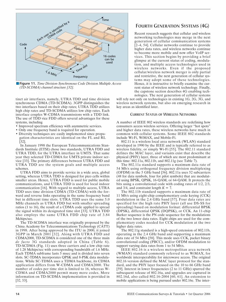
The TD-SCDMA interface was originally proposed by theChina Academy for Telecommunications Technology (CATT)in 1998. After being approved by the ITU in 2000, it joined3GPP in March 2001 [32]. Along with UTRA FDD andCDMA2000, TD-SCDMA is considered one of the three mainde facto 3G standards adopted in China (Table 6). TD-SCDMA (Fig. 11) uses three carriers and a low chip rateof 1.28 Mchips/sec with corresponding bandwidth of 1.6 MHz.Each TDMA subframe lasts 5 msec and is divided into sevenslots. SC-TDMA incorporates QPSK and 8-PSK data modula-tions. While SC-TDMA uses a TDMA backbone, its CDMAapplication differs from W-CDMA and CDMA2000. Thenumber of codes per time slot is limited to 16, whereas W-CDMA and CDMA2000 permit many more codes. Moreinformation on TD-SCDMA implementation is provided in[32, 53].
FOURTH GENERATION SYSTEMS (4G)Recent research suggests that cellular and wirelessnetworking technologies may merge in the nextgeneration of cellular communication systems[2–4, 54]. Cellular networks continue to providehigher data rates, and wireless networks continueto become more mobile and now offer VoIP ser-vices. This section begins by providing a briefglimpse at the current status of coding, modula-tion, and multiple access technologies used inwireless networks. Even if the proposedcellular/wireless network merger is only partialand restrictive, the next generation of cellular sys-tems may adopt some of these technologies.Hence, it is instructive to briefly examine the cur-rent status of wireless network technology. Finally,the capstone section describes 4G enabling tech-nologies. The next generation of cellular systems
will rely not only on technologies in existing 1G, 2G, 3G, andwireless network systems, but also on emerging research inkey areas as identified later.
CURRENT STATUS OF WIRELESS NETWORKS
A number of IEEE 802 wireless standards are redefining howconsumers access wireless services. Offering larger “hot spots”and higher data rates, these wireless networks have much incommon with cellular systems. Some IEEE 802 standardsinclude Wi-Fi, WiMAX, and Mobile-Fi.
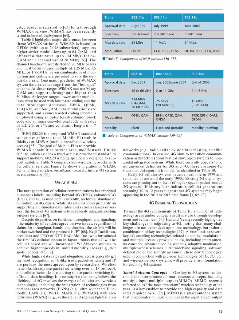
802.11 is a wireless local area network (WLAN) standarddeveloped in 1990 by the IEEE and is typically referred to aswireless fidelity, or simply Wi-Fi [55]. The 802.11 standarddefines the MAC layer, and variants exist that describe thephysical (PHY) layer, three of which are most predominant atthis time: 802.11a, 802.11b, and 802.11g (see Table 7).
The 802.11a standard supports a maximum data rate of 54 Mb/s using orthogonal frequency division multiplexing(OFDM) in the 5 GHz band [56]. 802.11a uses 52 subcarriers(48 for data symbols, four for pilot symbols) that are modulat-ed using BPSK, QPSK, 16-QAM, or 64-QAM. It protects thebits using a convolutional code with coding rates of 1/2, 2/3,and 3/4, and constraint length K = 7.
The 802.11b standard supports a maximum data rate of 11 Mb/s using eight-chip complementary code keying (CCK)modulation in the 2.4 GHz band [57]. Four data rates arespecified for the high rate PHY layer (all use DS-SS forspreading) based on modulation format: differential BPSK(DPSK), differential QPSK (DQPSK), or CCK. An 11-chipBarker sequence is the PN code sequence for the modulationsof the two lower data rates. Eight chips are used for the com-plementary codes needed for CCK modulation at the twohigher data rates.
The 802.11g standard is a high-speed extension of 802.11b,operating in the 2.4 GHz band and supporting a maximumdata rate of 54 Mb/s [58]. This mode uses CCK, packet binaryconvolutional coding (PBCC), and/or OFDM modulation tosupport varying data rates from 1 to 54 Mb/s.
IEEE 802.16 is a wireless metropolitan area network(WMAN) standard commonly referred to as WiMAX, forworldwide interoperability for microwave access. The original802.16 version defined the MAC layer protocol for the stan-dard, and the PHY layer focused on the 10 to 66 GHz band[59]. Interest in lower frequencies (2 to 11 GHz) spurred thesubsequent release of 802.16a, and upgrades are captured in802.16d, also called 802.16-2004 [60, 61]. An extension tomobile applications is being pursued under 802.16e. The inter-
IEEE Communications Surveys & Tutorials • 1st Quarter 200614
nFigure 11. Time Division-Synchronous Code Division Multiple Access(TD-SCDMA) channel structure [32].
1.6 MHz Frequency
Time slot
CodeEach user is
identified by a
CDMA code
Time
16 codescan beused
Downlink
DownlinkUplink
Downlink
IEEE Communications Surveys & Tutorials • 1st Quarter 2006 15
ested reader is referred to [63] for a thoroughWiMAX overview. WiMAX has been recentlytested in limited deployment [64].
Table 8 highlights major differences betweenthese WiMAX variants. WiMAX is based onOFDM (with up to 2,048 subcarriers), supportshigher-order modulations up to 64-QAM, andoffers raw data rates up to 134 Mb/s (for 64-QAM and a channel size of 28 MHz) [63]. Thechannel bandwidth is restricted to 20 MHz or lessand must be an integer multiple of 1.25 MHz, 1.5MHz, or 1.75 MHz. Seven combinations of mod-ulation and coding are provided to vary the out-put data rate. One major predictor of WiMAXsystem data rates is range from the “hot spot”antenna. At closer ranges WiMAX can use M-aryQAM and support throughputs higher than 50 Mb/s. At longer ranges, lower-order modula-tions must be used with lower-rate coding and thedata throughput decreases. BPSK, QPSK, 16-QAM, and 64-QAM data modulations aresupported, and a concatenated coding scheme isemployed using an outer Reed-Solomon blockcode and an inner convolutional code with ratesof 1/2, 2/3, or 3/4, and constraint length K = 7[63].
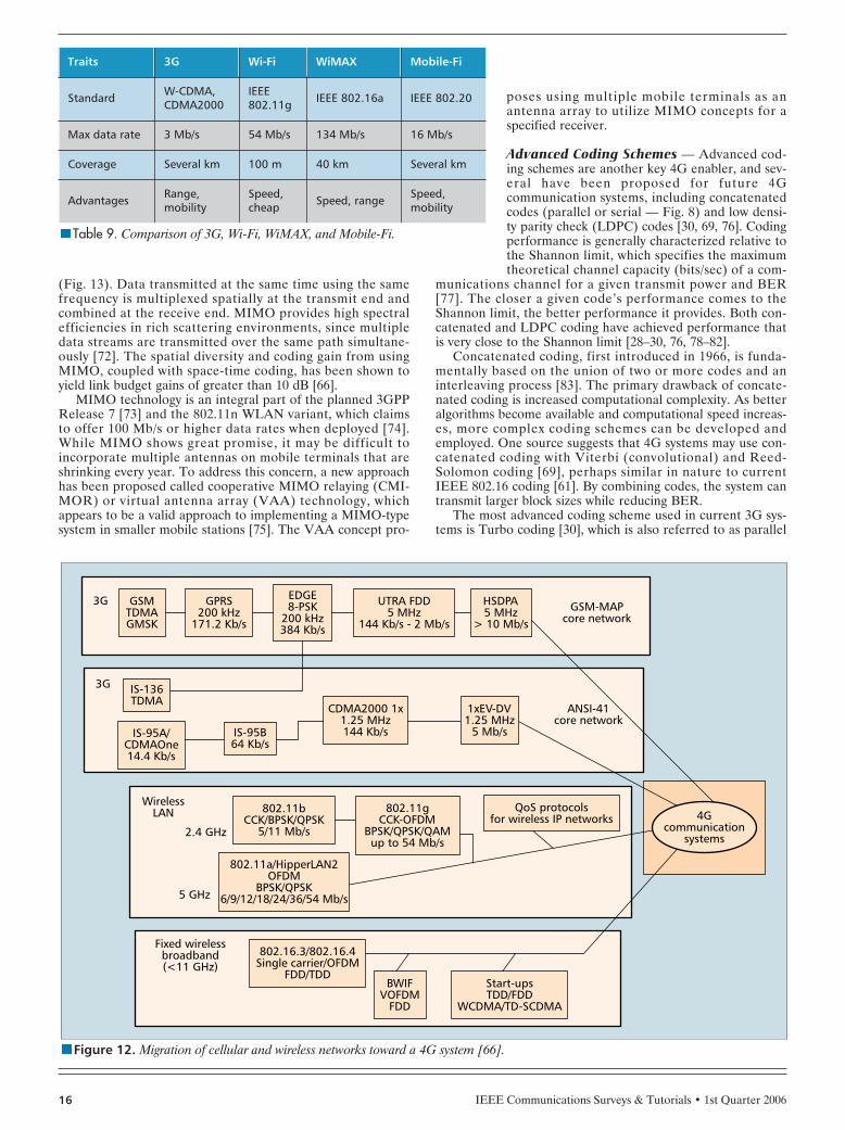
IEEE 802.20 is a proposed WMAN standardsometimes referred to as Mobile-Fi (mobilefidelity) or MBWA (mobile broadband wirelessaccess) [65]. The goal of Mobile-Fi is to provideWiMAX capabilities to wide area, mobile users. Unlike802.16e, which extends a fixed wireless broadband standard tosupport mobility, 802.20 is being specifically designed to sup-port mobility. Table 9 compares key wireless networks with3G cellular services. Figure 12 shows a migration of WLAN,3G, and fixed wireless broadband toward a future 4G systemas envisioned by [66].
WHAT IS 4G?
The next generation of cellular communications has inheritednumerous labels, including beyond 3G (B3G), enhanced 3G(E3G), and 4G as used here. Currently, no formal standard ordefinition for 4G exists. While 3G systems focus primarily onsupporting multimedia data rates and various classes of ser-vice, the focus of 4G systems is to seamlessly integrate existingwireless systems [67].
Despite disparities on timeline, throughput, and signaling,“the majority of vendors agree on two issues, regardless ofclaims for throughput, bands, and timeline: the air link will bepacket-switched and the protocol is IP” [68]. Keiji Tachikawa,president and CEO of NTT DoCoMo, Inc., who introducedthe first 3G cellular system in Japan, thinks that 4G will becellular-based and will incorporate WLAN-type systems toachieve higher speeds in limited mobility areas (e.g., hotspots, indoors, etc.) [2].
While higher data rates and ubiquitous access generally getthe most recognition as 4G-like traits, packet-switching and IPare perhaps the most agreed upon by researchers. Wirelessnetworks already use packet-switching over an IP protocol,and cellular networks are starting to use packet-switching forefficient data handling. It is no surprise that many believe thelifeblood of 4G involves the merger of cellular and wirelesstechnologies, including the integration of technologies frompersonal area networks (PANs) (e.g., ultra wideband, Blue-tooth), LANs (e.g., Wi-Fi), MANs (e.g., WiMAX), wide areanetworks (WANs) (e.g., cellular), and regional/global area
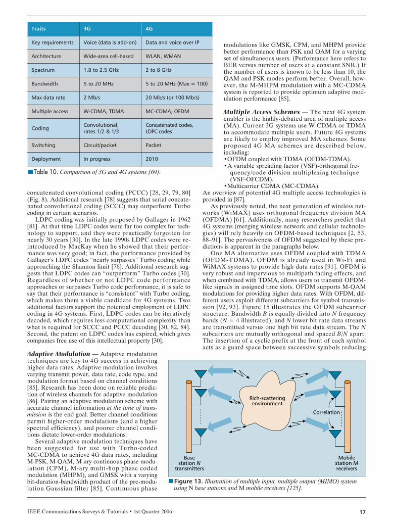
networks (e.g., radio and television broadcasting, satellitecommunications). In essence, 4G aims to transition communi-cation architectures from vertical stovepiped systems to hori-zontal integrated systems. While there currently appears to beno universal delimiter for 3G and 4G, there are some 4Gtraits that distinguish it from 3G, as identified in Table 10.
Early 1G cellular systems became available in 1979 andremained in use until the early 1990s. Existing 2G digital sys-tems are phasing out in favor of higher-speed, packet-routed3G systems. If history is an indicator, cellular generationsspanning 10 to 12 years suggest that 4G systems may beginappearing in the 2010 to 2015 time frame [3, 69, 70].
4G ENABLING TECHNOLOGIES
To meet the 4G requirements of Table 10, a number of tech-nology areas and/or concepts must mature through develop-ment and refinement [54]. Hui and Yeung recently highlightedkey challenges in migrating to 4G, noting that many chal-lenges are not dependent upon one technology, but rather acombination of key technologies [67]. A brief look at severalkey 4G enabling technologies related to coding, modulation,and multiple access is provided below, including smart anten-na concepts, advanced coding schemes, adaptive modulation,multiple access schemes, ultra wideband signaling, softwaredefined radio, and security measures. These new technologies,used in conjunction with previous technologies of 1G, 2G, 3G,and wireless network systems, will provide a firm foundationfor enabling 4G systems.
Smart Antenna Concepts — One key to 4G system realiza-tion is the incorporation of smart antenna concepts, includingmultiple input multiple output (MIMO). MIMO, recentlyreferred to as “the most important” wireless technology of theyear, is a key enabler to provide the high capacity and datarates required by 4G [71]. MIMO is a smart antenna systemthat incorporates multiple antennas at the input and/or output
nTable 7. Comparison of wi-fi variants [56–58].
Traits 802.11a 802.11b 802.11g
Approval date July 1999 July 1999 June 2003
Spectrum 5 GHz band 2.4 GHz band 5 GHz band
Max data rate 54 Mb/s 11 Mb/s 54 Mb/s
Modulation OFDM CCK, PBCC, DSSS OFDM, PBCC, CCK, DSSS
nTable 8. Comparison of WiMAX variants [59–62].
Traits 802.16 802.16a/d 802.16e
Approval date Dec 2001 Jan. 2003/June 2004 End of 2005
Spectrum 10 to 66 GHz 2 to 11 GHz 2 to 6 GHz
Max data rate134 Mb/s(64-QAM, 28 MHz Ch)
75 Mb/s(20 MHz Ch)
15 Mb/s(5 MHz Ch)
Modulation QPSK, QAM BPSK, QPSK, QAM,OFDM
BPSK,QPSK, QAM,OFDM
Mobility Fixed Fixed and portable Mobility, roaming
IEEE Communications Surveys & Tutorials • 1st Quarter 200616
(Fig. 13). Data transmitted at the same time using the samefrequency is multiplexed spatially at the transmit end andcombined at the receive end. MIMO provides high spectralefficiencies in rich scattering environments, since multipledata streams are transmitted over the same path simultane-ously [72]. The spatial diversity and coding gain from usingMIMO, coupled with space-time coding, has been shown toyield link budget gains of greater than 10 dB [66].
MIMO technology is an integral part of the planned 3GPPRelease 7 [73] and the 802.11n WLAN variant, which claimsto offer 100 Mb/s or higher data rates when deployed [74].While MIMO shows great promise, it may be difficult toincorporate multiple antennas on mobile terminals that areshrinking every year. To address this concern, a new approachhas been proposed called cooperative MIMO relaying (CMI-MOR) or virtual antenna array (VAA) technology, whichappears to be a valid approach to implementing a MIMO-typesystem in smaller mobile stations [75]. The VAA concept pro-
poses using multiple mobile terminals as anantenna array to utilize MIMO concepts for aspecified receiver.
Advanced Coding Schemes — Advanced cod-ing schemes are another key 4G enabler, and sev-eral have been proposed for future 4Gcommunication systems, including concatenatedcodes (parallel or serial — Fig. 8) and low densi-ty parity check (LDPC) codes [30, 69, 76]. Codingperformance is generally characterized relative tothe Shannon limit, which specifies the maximumtheoretical channel capacity (bits/sec) of a com-
munications channel for a given transmit power and BER[77]. The closer a given code’s performance comes to theShannon limit, the better performance it provides. Both con-catenated and LDPC coding have achieved performance thatis very close to the Shannon limit [28–30, 76, 78–82].
Concatenated coding, first introduced in 1966, is funda-mentally based on the union of two or more codes and aninterleaving process [83]. The primary drawback of concate-nated coding is increased computational complexity. As betteralgorithms become available and computational speed increas-es, more complex coding schemes can be developed andemployed. One source suggests that 4G systems may use con-catenated coding with Viterbi (convolutional) and Reed-Solomon coding [69], perhaps similar in nature to currentIEEE 802.16 coding [61]. By combining codes, the system cantransmit larger block sizes while reducing BER.
The most advanced coding scheme used in current 3G sys-tems is Turbo coding [30], which is also referred to as parallel
nFigure 12. Migration of cellular and wireless networks toward a 4G system [66].
3G
3G
2.4 GHz
5 GHz
WirelessLAN
GSMTDMAGMSK
IS-136TDMA
IS-95B64 Kb/s
EDGE8-PSK
200 kHz384 Kb/s
GPRS200 kHz
171.2 Kb/s
IS-95A/CDMAOne14.4 Kb/s
CDMA2000 1x1.25 MHz144 Kb/s
802.11bCCK/BPSK/QPSK
5/11 Mb/s
802.16.3/802.16.4Single carrier/OFDM
FDD/TDD
Fixed wirelessbroadband(<11 GHz)
BWIFVOFDM
FDD
Start-upsTDD/FDD
WCDMA/TD-SCDMA
802.11gCCK-OFDM
BPSK/QPSK/QAMup to 54 Mb/s
802.11a/HipperLAN2OFDM
BPSK/QPSK6/9/12/18/24/36/54 Mb/s
QoS protocolsfor wireless IP networks
1xEV-DV1.25 MHz
5 Mb/s
ANSI-41core network
HSDPA5 MHz
> 10 Mb/sGSM-MAP
core networkUTRA FDD
5 MHz144 Kb/s - 2 Mb/s
4Gcommunication
systems
nTable 9. Comparison of 3G, Wi-Fi, WiMAX, and Mobile-Fi.
Traits 3G Wi-Fi WiMAX Mobile-Fi
Standard W-CDMA,CDMA2000
IEEE802.11g IEEE 802.16a IEEE 802.20
Max data rate 3 Mb/s 54 Mb/s 134 Mb/s 16 Mb/s
Coverage Several km 100 m 40 km Several km
Advantages Range,mobility
Speed,cheap Speed, range Speed,
mobility
IEEE Communications Surveys & Tutorials • 1st Quarter 2006 17
concatenated convolutional coding (PCCC) [28, 29, 79, 80](Fig. 8). Additional research [78] suggests that serial concate-nated convolutional coding (SCCC) may outperform Turbocoding in certain scenarios.
LDPC coding was initially proposed by Gallager in 1962[81]. At that time LDPC codes were far too complex for tech-nology to support, and they were practically forgotten fornearly 30 years [30]. In the late 1990s LDPC codes were re-introduced by MacKay when he showed that their perfor-mance was very good; in fact, the performance provided byGallager’s LDPC codes “nearly surpasses” Turbo coding whileapproaching the Shannon limit [76]. Additional research sug-gests that LDPC codes can “outperform” Turbo codes [30].Regardless of whether or not LDPC code performanceapproaches or surpasses Turbo code performance, it is safe tosay that their performance is “consistent” with Turbo coding,which makes them a viable candidate for 4G systems. Twoadditional factors support the potential employment of LDPCcoding in 4G systems. First, LDPC codes can be iterativelydecoded, which requires less computational complexity thanwhat is required for SCCC and PCCC decoding [30, 82, 84].Second, the patent on LDPC codes has expired, which givescompanies free use of this intellectual property [30].
Adaptive Modulation — Adaptive modulationtechniques are key to 4G success in achievinghigher data rates. Adaptive modulation involvesvarying transmit power, data rate, code type, andmodulation format based on channel conditions[85]. Research has been done on reliable predic-tion of wireless channels for adaptive modulation[86]. Pairing an adaptive modulation scheme withaccurate channel information at the time of trans-mission is the end goal. Better channel conditionspermit higher-order modulations (and a higherspectral efficiency), and poorer channel condi-tions dictate lower-order modulations.
Several adaptive modulation techniques havebeen suggested for use with Turbo-coded MC-CDMA to achieve 4G data rates, includingM-PSK, M-QAM, M-ary continuous phase modu-lation (CPM), M-ary multi-hop phase codedmodulation (MHPM), and GMSK with a varyingbit-duration-bandwidth product of the pre-modu-lation Gaussian filter [85]. Continuous phase
modulations like GMSK, CPM, and MHPM providebetter performance than PSK and QAM for a varyingset of simultaneous users. (Performance here refers toBER versus number of users at a constant SNR.) Ifthe number of users is known to be less than 10, theQAM and PSK modes perform better. Overall, how-ever, the M-MHPM modulation with a MC-CDMAsystem is reported to provide optimum adaptive mod-ulation performance [85].
Multiple Access Schemes — The next 4G systemenabler is the highly-debated area of multiple access(MA). Current 3G systems use W-CDMA or TDMAto accommodate multiple users. Future 4G systemsare likely to employ improved MA schemes. Someproposed 4G MA schemes are described below,including:•OFDM coupled with TDMA (OFDM-TDMA).•A variable spreading factor (VSF)-orthogonal fre-
quency/code division multiplexing technique(VSF-OFCDM).
•Multicarrier CDMA (MC-CDMA).An overview of potential 4G multiple access technologies isprovided in [87].
As previously noted, the next generation of wireless net-works (WiMAX) uses orthogonal frequency division MA(OFDMA) [61]. Additionally, many researchers predict that4G systems (merging wireless network and cellular technolo-gies) will rely heavily on OFDM-based techniques [2, 53,88–91]. The pervasiveness of OFDM suggested by these pre-dictions is apparent in the paragraphs below.
One MA alternative uses OFDM coupled with TDMA(OFDM-TDMA). OFDM is already used in Wi-Fi andWiMAX systems to provide high data rates [91]. OFDM isvery robust and impervious to multipath fading effects, andwhen combined with TDMA, allows users to transmit OFDM-like signals in assigned time slots. OFDM supports M-QAMmodulations for providing higher data rates. With OFDM, dif-ferent users exploit different subcarriers for symbol transmis-sion [92, 93]. Figure 15 illustrates the OFDM subcarrierstructure. Bandwidth B is equally divided into N frequencybands (N = 4 illustrated), and N lower bit rate data streamsare transmitted versus one high bit rate data stream. The Nsubcarriers are mutually orthogonal and spaced B/N apart.The insertion of a cyclic prefix at the front of each symbolacts as a guard space between successive symbols reducing
nFigure 13. Illustration of multiple input, multiple output (MIMO) systemusing N base stations and M mobile receivers [125].
Correlation
Mobilestation Mreceivers
Basestation N
transmitters
Rich-scatteringenvironment
nTable 10. Comparison of 3G and 4G systems [69].
Traits 3G 4G
Key requirements Voice (data is add-on) Data and voice over IP
Architecture Wide-area cell-based WLAN, WMAN
Spectrum 1.8 to 2.5 GHz 2 to 8 GHz
Bandwidth 5 to 20 MHz 5 to 20 MHz (Max = 100)
Max data rate 2 Mb/s 20 Mb/s (or 100 Mb/s)
Multiple access W-CDMA, TDMA MC-CDMA, OFDM
Coding Convolutional,rates 1/2 & 1/3
Concatenated codes,LDPC codes
Switching Circuit/packet Packet
Deployment In progress 2010
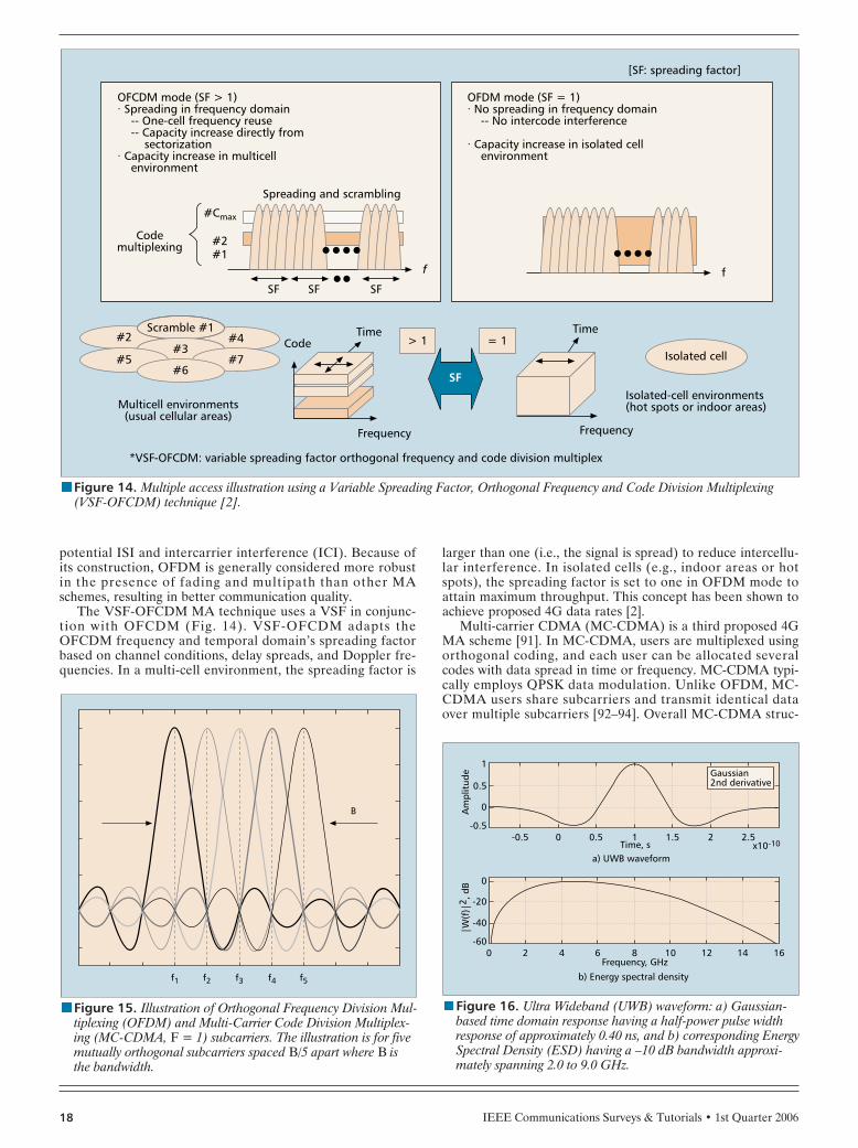
IEEE Communications Surveys & Tutorials • 1st Quarter 200618
potential ISI and intercarrier interference (ICI). Because ofits construction, OFDM is generally considered more robustin the presence of fading and multipath than other MAschemes, resulting in better communication quality.
The VSF-OFCDM MA technique uses a VSF in conjunc-tion with OFCDM (Fig. 14). VSF-OFCDM adapts theOFCDM frequency and temporal domain’s spreading factorbased on channel conditions, delay spreads, and Doppler fre-quencies. In a multi-cell environment, the spreading factor is
larger than one (i.e., the signal is spread) to reduce intercellu-lar interference. In isolated cells (e.g., indoor areas or hotspots), the spreading factor is set to one in OFDM mode toattain maximum throughput. This concept has been shown toachieve proposed 4G data rates [2].
Multi-carrier CDMA (MC-CDMA) is a third proposed 4GMA scheme [91]. In MC-CDMA, users are multiplexed usingorthogonal coding, and each user can be allocated severalcodes with data spread in time or frequency. MC-CDMA typi-cally employs QPSK data modulation. Unlike OFDM, MC-CDMA users share subcarriers and transmit identical dataover multiple subcarriers [92–94]. Overall MC-CDMA struc-
nFigure 14. Multiple access illustration using a Variable Spreading Factor, Orthogonal Frequency and Code Division Multiplexing(VSF-OFCDM) technique [2].
> 1 = 1CodeTime Time
Isolated cell
Isolated-cell environments(hot spots or indoor areas)
Frequency
*VSF-OFCDM: variable spreading factor orthogonal frequency and code division multiplex
Frequency
Multicell environments(usual cellular areas)
[SF: spreading factor]
OFCDM mode (SF > 1)· Spreading in frequency domain -- One-cell frequency reuse -- Capacity increase directly from sectorization· Capacity increase in multicell environment
OFDM mode (SF = 1)· No spreading in frequency domain -- No intercode interference · Capacity increase in isolated cell environment
Codemultiplexing
#1#2
#Cmax
SF
Spreading and scrambling
f
SF SFf
#4#2Scramble #1
SF
#3#7#5
#6
nFigure 15. Illustration of Orthogonal Frequency Division Mul-tiplexing (OFDM) and Multi-Carrier Code Division Multiplex-ing (MC-CDMA, F = 1) subcarriers. The illustration is for fivemutually orthogonal subcarriers spaced B/5 apart where B isthe bandwidth.
f1 f2 f3 f4 f5
B
nFigure 16. Ultra Wideband (UWB) waveform: a) Gaussian-based time domain response having a half-power pulse widthresponse of approximately 0.40 ns, and b) corresponding EnergySpectral Density (ESD) having a –10 dB bandwidth approxi-mately spanning 2.0 to 9.0 GHz.
2.5
0.5
Time, s
Frequency, GHz
a) UWB waveformx10-10
-0.5
Am
plit
ude
0
1
21.510.50-0.5
Gaussian2nd derivative
b) Energy spectral density
14 16-60
-20
|W(f
)|2 ,
dB 0
-40
121086420
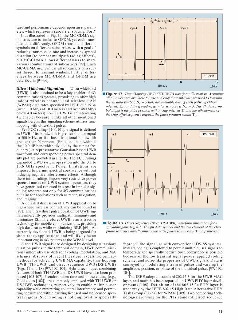
IEEE Communications Surveys & Tutorials • 1st Quarter 2006 19
ture and performance depends upon an F param-eter, which represents subcarrier spacing. For F= 1, as illustrated in Fig. 15, the MC-CDMA sig-nal structure is similar to OFDM, yet each trans-mits data differently. OFDM transmits differentsymbols on different subcarriers, with a goal ofreducing transmission rate and increasing symbolduration (to combat multipath fading effects),but MC-CDMA allows different users to sharevarious combinations of subcarriers [92]. EachMC-CDMA user can use all subcarriers or a sub-set thereof to transmit symbols. Further differ-ences between MC-CDMA and OFDM aredescribed in [94–96].
Ultra Wideband Signaling — Ultra wideband(UWB) is also destined to be a key enabler of 4Gcommunications systems, promising to offer highindoor wireless channel and wireless PAN(WPAN) data rates specified by IEEE 802.15.3a(over 110 Mb/s at 10.0 meters and over 480 Mb/sbelow 4.0 meters) [97-99]. UWB is an interesting4G enabler because, unlike all other mentionedsignals herein, this signaling scheme utilizes timehopping with ultra-short pulses.
Per FCC rulings [100,101], a signal is definedas UWB if its bandwidth is greater than or equalto 500 MHz, or if it has a fractional bandwidthgreater than 20 percent. (Fractional bandwidth isthe 10.0 dB bandwidth divided by the center fre-quency.) A representative Gaussian-based UWBwaveform and corresponding power spectral den-sity plot are provided in Fig. 16. The FCC rulingsexpanded UWB system operation into the 3.1 to10.6 GHz spectrum. Power limitations areimposed to permit spectral coexistence withoutinducing negative interference effects. Althoughthese initial rulings impose very restrictive powerspectral masks on UWB system operation, theyhave generated renewed interest in impulse sig-naling research not only for 4G communicationsbut also for applications such as radar, navigation,and imaging.
A detailed discussion of UWB application tohigh-speed wireless connectivity can be found in[97]. The ultra-short pulse duration of UWB sig-nals inherently provides multipath immunity andminimizes ISI. Therefore, UWB is an attractivetechnology for mobile communications, providinghigh data rates while minimizing BER [69]. Ascurrently developed, UWB is being targeted forshort range applications and will likely be animportant cog in 4G systems at the WPAN level.
Since UWB signals are designed by designing ultrashortduration pulses in the temporal domain, UWB communica-tions inherently use different coding, modulation, and MAschemes. A survey of recent literature reveals two primarymethods for achieving UWB MA capability: time hoppingUWB (TH-UWB) and direct sequence UWB (DS-UWB)(Figs. 17 and 18) [97, 102–104]. Hybrid techniques combiningfeatures of both TH-UWB and DS-UWB have also been pro-posed [105-107]. Pseudorandom time and phase coding (e.g.,Gold codes [102]) are commonly employed with TH-UWB orDS-UWB techniques, respectively, to enable multiple usercapability while minimizing collateral interference and permit-ting coexistence within existing licensed and unlicensed spec-tral regions. Such coding is not employed to spectrally
“spread” the signal, as with conventional DS-SS systems;instead, coding is employed to permit multiple user signals totemporally and spectrally coexist. Such coexistence is possiblebecause of the low transmit signal power, applied codingscheme, and noise-like properties of UWB signals. Data isconveyed by modulating a train of pulses and varying theamplitude, position, or phase of the individual pulses [97, 102,104].
The IEEE adopted standard 802.15.3 for the UWB MAClayer, and much has been reported on UWB PHY layer devel-opments [108]. Definition of the 802.15.3a PHY layer isunderway by the IEEE 802.15 High Rate Alternative PHYTask Group (TG3a) for WPAN [109]. Two competing tech-nologies are vying for the PHY standard: direct sequence
nFigure 17. Time Hopping UWB (TH-UWB) waveform illustration. Assumingall time slots are available for use and only these intervals are used to transmitthe jth data symbol, Ns = 5 slots are available during each pulse repetitioninterval, To , and the spreading gain for symbol j is Nss = 3. The jth data sym-bol impacts the pulse position within chip interval Tc and the nth element ofthe chip offset sequence impacts the pulse position within To .
Time, s8 12
x10-9
4
To
Tc
cn=4 cn=3 cn=1
0
∆
dj,jth data symbol, +1
TH-PPM
nFigure 18. Direct Sequence UWB (DS-UWB) waveform illustration for aspreading gain, Nss = 5. The jth data symbol and the nth element of the chipphase sequence directly impact the pulse phase within each Tc chip interval.
Time, s
DS-UWB
4
Tc
To
+1
+1 +1 -1
+1 +10 0
6
x10-9
0 2
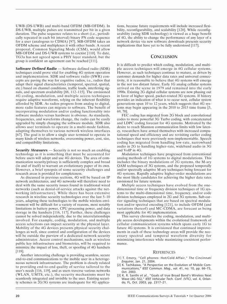
IEEE Communications Surveys & Tutorials • 1st Quarter 200620
UWB (DS-UWB) and multi-band OFDM (MB-OFDM). InDS-UWB, multiple pulses are transmitted per bit in a givenduration. The pulse sequence relates to a short (i.e., periodi-cally repeated in each bit interval) binary PN code sequencefor a user (analogous to CDMA) [97]. MB-OFDM takes anOFDM scheme and multiplexes it with other bands. A recentproposal, Common Signaling Mode (CSM), would allow MB-OFDM and DS-UWB systems to coexist [110]. To date,TG3a has not agreed upon a PHY layer standard, but thegroup is confident an agreement can be reached [111].
Software Defined Radio — Software defined radio (SDR)techniques could prove vital for enabling 4G system operationand implementation. SDR and software radio (SWR) con-cepts are paving the way for cognitive radios, i.e., radios thatadapt their signal characteristics (temporal, spectral, spatial,etc.) based on channel conditions, traffic loads, interfering sig-nals, and spectrum availability [88, 112–115]. The envisioned4G coding, modulation, and multiple access techniquesrequire adaptive waveforms, relying on the inherent flexibilityafforded by SDR. As radios progress from analog to digital,more radio features can migrate to software. The benefit ofincorporating modulation and/or coding functionality intosoftware modules versus hardware is obvious. As standards,frequencies, and waveforms change, the radio can be easilyupgraded by simply changing the software module. SDR alsoallows user terminals to operate in a multi-mode fashion,adapting themselves to various network wireless interfaces[67]. The goal is to allow a single user terminal to operate inmany kinds of wireless networks, overcoming power, cost, size,and compatibility limitations.
Security Measures — Security is not so much an enablingtechnology as it is something that must be accounted forbefore users will adopt and use 4G devices. The area of com-munication security/privacy is sufficiently complex and broad(in and of itself) to warrant an evolutionary paper of its own.However, a brief synopsis of some security challenges andresearch areas is provided for completeness.
As discussed in previous sections, 4G will be based on IPnetwork architectures, and 4G networks will therefore need todeal with the same security issues found in traditional wirednetworks (such as denial-of-service attacks against the net-working infrastructure). While there has been extensiveresearch in wireline security technologies over the last 5–10years, adapting these technologies to the mobile wireless envi-ronment will be difficult for a variety of reasons, most notablylimitations in battery power, CPU processing power, and datastorage in the handsets [116, 117]. Further, these challengescannot be solved independently, due to the interrelationshipsinvolved. For example, coding, modulation, and multipleaccess selections can impact security at the physical layer.Mobility of the 4G devices presents physical security chal-lenges as well, since control and configuration of the deviceswill be outside the purview of a dedicated network securityadministrator. Access control mechanisms, such as wirelesspublic key infrastructure and biometrics, will be required tominimize the impact of loss, theft, or spoofing of 4G handsets[118].
Another interesting challenge is providing seamless, secureend-to-end communications to the mobile user in a heteroge-neous network infrastructure. The problem is closely relatedto providing end-to-end quality of service tailored to theuser’s needs [116, 119], and as users traverse various networks(WLAN, UMTS, etc.), the security mechanisms must beseamlessly integrated and invisible to the user. Existing securi-ty schemes in 2G/3G systems are inadequate for 4G applica-
tions, because future requirements will include increased flexi-bility, reconfigurability, and scalability [120]. While reconfig-urability (using SDR technology) is viewed as a huge benefitof 4G, the ability to change the performance of any layer of anetwork device via new software downloads presents securityimplications that have yet to be fully understood [117].
CONCLUSION
It is difficult to predict which coding, modulation, and multi-ple access techniques will emerge in 4G cellular systems.However, as such techniques continue to mature, as driven bycustomer demands for higher data rates and universal connec-tivity, it is reasonable to believe that 4G systems will emergein the not too distant future. Early 1G analog cellular systemsarrived on the scene in 1979 and remained into the early1990s. Existing 2G digital cellular systems are now phasing outin favor of higher speed, packet-routed 3G systems. If historyprovides an indication of what is to occur next, cellular systemgenerations span 10 to 12 years, which suggests that 4G sys-tems may begin appearing in the 2010 to 2015 time frame [3,69, 70].
FEC coding has migrated from 2G block and convolutionalcodes to more powerful 3G Turbo coding, with concatenatedand LDPC coding forecast for 4G systems. Motivated by thedesire to reach Shannon communication limits with low laten-cy, researchers have armed themselves with increased compu-tational speed and efficiency and are revisiting earlier codingtechniques that were previously non-implementable. Speechcoding has migrated from handling low-rate, narrowbandaudio in 2G to handling higher-rate, wideband audio in 3Gand VoIP in 4G.
Modulation techniques have progressed from conventionalanalog methods of 1G systems to digital modulations. Thisincludes the binary modulations of 2G systems, the M-aryQAM techniques of 3G systems, and the proposed temporallyand/or spectrally adaptive M-ary techniques being forecast for4G systems. Rapidly adaptive higher-order modulations arethe most likely candidates for achieving the higher data ratesenvisioned for future systems.
Multiple access techniques have evolved from the one-dimensional time or frequency division techniques of 1G sys-tems to the multi-dimensional time, frequency, and/or codedivision techniques employed in 2G and 3G systems. Sub-car-rier signaling techniques that are based on spectral modula-tion and/or spectral encoding [121], to include OFDM (andvariations thereof) and MC-CDMA, are forecast as beingmost applicable for 4G implementation.
This survey chronicles the coding, modulation, and multi-ple access developments within the evolutional framework ofcellular communication systems which spans early 1G tofuture 4G systems. It is envisioned that continued improve-ments in each of these technology areas will provide the nec-essary spectral and temporal waveform diversity forminimizing interference while maximizing coexistent perfor-mance.
REFERENCES[1] T. Emery, “Cell phones: Hot/Cold Affair,” The Cincinnati
Enquirer, Jan. 21, 2004.[2] K. Tachikawa, “A Perspective on the Evolution of Mobile Com-
munications,” IEEE Commun. Mag., vol. 41, no. 10, pp. 66–73,Oct. 2003.
[3] K. R. Santhi et al., “Goals of true Broad Band’s Wireless NextWave (4G–5G),” IEEE Vehicular Tech. Conf. (VTC), vol. 4, Orlan-do, FL, Oct. 2003, pp. 2317–21.
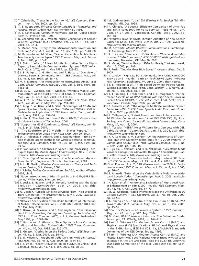
IEEE Communications Surveys & Tutorials • 1st Quarter 2006 21
[4] T. Zahariadis, “Trends in the Path to 4G,” IEE Commun. Engr.,vol. 1, no. 1, Feb. 2003, pp. 12–15.
[5] T. S. Rappaport, Wireless Communications: Principles andPractice, Upper Saddle River, NJ: Prentice-Hall, 1996.
[6] A. S. Tanenbaum, Computer Networks, 3rd Ed., Upper SaddleRiver, NJ: Prentice-Hall, 1996.
[7] N. Chandran and M. C. Valenti, “Three Generations of CellularWireless Systems,” IEEE Potentials, vol. 20, no. 1, Feb.–Mar.2001, pp. 32–35.
[8] S. Mazor, “The History of the Microcomputer-Invention andEvolution,” Proc. IEEE, vol. 83, no. 12, Dec. 1995, pp. 1601–08.
[9] M. Kuramoto and M. Shinji, “Second Generation Mobile RadioTelephone System in Japan,” IEEE Commun. Mag., vol. 24, no.2, Feb. 1986, pp. 16–21.
[10] I. Shimizu et al., “A New Mobile Subscriber Set for High-Capacity Land Mobile Communication System,” IEEE Vehic.Tech. Conf. (VTC), vol. 1, May 1989, pp. 228–32.
[11] J. E. Padgett, C. G. Günther, and T. Hattori, “Overview ofWireless Personal Communications,” IEEE Commun. Mag., vol.33, no. 1, Jan. 1995, pp. 28–41.
[12] M. P. Metroka, “An Introduction to Narrowband Amps,” IEEEConf. Global Commun. (GLOBECOM), vol. 2, Dec. 1991, pp.1463–68.
[13] Q. Bi, G. I. Zysman, and H. Menkes, “Wireless Mobile Com-munications at the Start of the 21st Century,” IEEE Commun.Mag., vol. 39, no. 1, Jan. 2001, pp. 110–16.
[14] W. C. Y. Lee, “Overview of Cellular CDMA,” IEEE Trans. Vehic.Tech., vol. 40, no. 2, May 1991, pp. 291–302.
[15] P. Jung, P. W. Baier, and A. Steil, “Advantages of CDMA andSpread Spectrum Techniques Over FDMA and TDMA in CellularMobile Radio Applications,” IEEE Trans. Vehic. Tech., vol. 42,no. 3, Aug. 1993, pp. 357–64.
[16] A. Kölbl, “The Evolution from GSM to UMTS,” Master’s the-sis, Vienna Institute of Technology, 2001.
[17] “Support for GSM Continues to Grow,” IEE Review, vol. 50,no. 3, p. 21, Mar. 2004.
[18] “The Evolution to 3G Mobile — Status Report,” Int’l.Telecommunication Union (ITU) News Mag., July 29, 2003.
[19] D. D. Falconer, F. Adachi, and B. Gudmundson, “Time divi-sion multiple access methods for wireless personal communi-cations,” IEEE Commun. Mag., vol. 33, no. 1, Jan. 1995, pp.50–57.
[20] P. VanRooyen, “Advances in Space-Time Processing Tech-niques Open Up Mobile Apps,” CommsDesign, Nov. 8, 2002,available: http://www.commsdesign.com/
[21] B. Sklar, Digital Communications: Fundamentals and Applica-tions, 2nd Ed., Englewood Cliffs, NJ: Prentice-Hall, 2001.
[22] A. U. H. Sheikh, Wireless Communications Theory and Tech-niques, Boston, MA: Kluwer, 2004.
[23] J. Schiller, Mobile Communications, 2nd Ed., Addison-Wesley,2003, ch. 4.
[24] “Edge: Introduction of High-Speed Data in GSM/GPRS Net-works,” White Paper, Ericsson, 2003.
[25] T. Locke, S. Nguyen, and D. Moreuil, “Dealing with the EdgeEvolution,” CommsDesign, Sept. 24, 2002, available:http://www.commsdesign.com/
[26] A. Dornan, “Mobile Satellite Services: From Third World toThird Generation,” IT Architect Mag., July 7, 2002, available:http://www.itarchitect.com/
[27] “Detailed Specification of the Radio Interfaces of Internation-al Mobile Telecommunications — 2000 (IMT-2000),” ITU-R Rec.M.1457, May 2000.
[28] C. Berrou, A. Glavieux, and P. Thitimajshima, “Near ShannonLimit Error-Correcting Coding and Decoding: Turbo-Codes,”IEEE Int’l. Conf. Commun. (ICC), vol. 2, Geneva, Switzerland,May 1993, pp. 1064–70.
[29] C. Berrou and A. Glavieux, “Near Optimum Error CorrectingCoding and Decoding: Turbo-Codes,” IEEE Trans. Commun.,vol. 44, no. 10, Oct. 1996, pp. 1261–71.
[30] E. Guizzo, “Closing in on the Perfect Code,” IEEE Spectrum,vol. 41, no. 3, Mar. 2004, pp. 36–42.
[31] L. B. Milstein, “Wideband Code Division Multiple Access,”IEEE JSAC, vol. 18, no. 8, Aug. 2000, pp. 1344–54.
[32] B. Li et al., “Recent Advances on TD-SCDMA in China,” IEEECommun. Mag., vol. 43, no. 1, Jan. 2005, pp. 30–37.
[33] M. Gudmundson, “Utra,” TIA Wireless Info. Session ’98, Min-neapolis, MN, Oct. 1998.
[34] A. Chheda, “A Spectral Efficiency Comparison of Umts-Fddand 1×RTT cdma2000 for Voice Services,” IEEE Vehic. Tech.Conf. (VTC), vol. 1, Vancouver, Canada, Sept. 2002, pp.554–58.
[35] “Progress Towards UMTS Through Adoption of New SpeechCodec for GSM,” ETSI Press Release, Oct. 20, 1998, available:http://www.etsi.com/pressroom/
[36] M. Schwartz, Mobile Wireless Communications, Cambridge,UK: Cambridge Univ. Press, 2005.
[37] R. E. Ziemer, “Diversity in 3G Wireless — Wideband and Mul-ticarrier CDMA Compared,” IEEE COMSOC distinguished lec-ture series, Beaverton, OR, May 30, 2001.
[38] S. Marek, “Vendors Ready HSDPA for Reality,” Wireless Week,Mar. 15, 2005, pp. 8–9.
[39] S. Rush, “Cingular Goes High Speed,” Wireless Week, Dec. 6,2005.
[40] S. Lundby, “High-rate Data Communications Using cdma20001×ev-do and 1×ev-dv,” 14th VA Tech/MPRG Symp. WirelessPers. Commun., Blacksburg, VA, June 9, 2004, short course.
[41] T. E. Kolding et al., “High-Speed Downlink Packet Access:Wcdma Evolution,” IEEE Vehic. Tech. Society (VTS) News, vol.50, no. 1, Feb. 2003, pp. 4–10.
[42] T. E. Kolding, F. Frederiksen, and P. E. Mogensen, “Perfor-mance Aspects of WCDMA Systems with High Speed DownlinkPacket Access (HSDPA),” IEEE Vehic. Tech. Conf. (VTC), vol. 1,Vancouver, Canada, Sept. 2002, pp. 477–81.
[43] B. Bessette et al., “The Adaptive Multirate Wideband SpeechCodec (Amr-Wb),” IEEE Trans. Speech Audio Proc., vol. 10, no.8, Nov. 2002, pp. 620–36.
[44] R. Yallapragada, “Latest Trends and New Enhancements in3G Wireless Communications,” Joint IEEE COMSOC, Sig. Proc.Society, and Comp. Society distinguished lecture series, CostaMesa, CA, Apr. 12, 2004.
[45] A. Toskala, “HSDPA Helps W-Cdma Nets Compete with DSL,Cable Services,” CommsDesign, Jan. 13, 2004, available:http://www.commsdesign.com/
[46] R. A. Soni and R. M. Buehrer, “On the Performance of Open-loop Transmit Diversity Techniques for IS-2000 Systems: AComparative Study,” IEEE Trans. Wireless Commun., vol. 3, no.5, Sept. 2004, pp. 1602–15.
[47] H. yu Su, E. Shlomot, and H. K. Nakamura, “Selectable ModeVocoder Emerges for cdma2000 Designs,” CommsDesign, Jan.7, 2003, available: http://www.commsdesign.com/
[48] S. Kwon et al., “Power Controlled H-Arq in cdma2000 1×ev-dv,” IEEE Commun. Mag., vol. 43, no. 4, Apr. 2005, pp. 77–81.
[49] Y.-K. Kim and B. K. Yi, “3G Wireless and cdma2000 1× Evolu-tion in Korea,” IEEE Commun. Mag., vol. 43, no. 4, Apr. 2005,pp. 36–40.
[50] S. Ahmadi, “Tutorial on the Variable-Rate Multimode Wide-band Speech Codec,” CommsDesign, Sept. 2, 2003, available:http://www.commsdesign.com/
[51] H. Kwon et al., “Performance Evaluation of High-Speed Pack-et Enhancement on cdma2000 1×ev-dv,” IEEE Commun. Mag.,vol. 43, no. 4, Apr. 2005, pp. 67–73.
[52] M. W. Oliphant, “Radio Interfaces Make the Difference in 3GCellular Systems,” IEEE Spectrum, vol. 37, no. 10, Oct. 2000,pp. 53–58.
[53] K. Zheng et al., “Td-cdm-ofdm: Evolution of TD-SCDMAToward 4G,” IEEE Commun. Mag., vol. 43, no. 1, Jan. 2005,pp. 45–52.
[54] “Call for Papers — 4G Wireless Systems,” IEEE Commun.Mag., vol. 42, no. 8, p. S47, Aug. 2004.
[55] M. Gast, 802.11Wireless Networks: The Definitive Guide.Sebastopol, CA: O’Reilly, 2002, pp. 164–213.
[56] Part 11: Wireless LAN Medium Access Control (MAC) andPhysical Layer (PHY) Specifications: High-Speed Physical Layerin the 5 GHz Band, IEEE Std 802.11a, LAN/MAN StandardsCommittee of the IEEE Comp. Society, 1999.
[57] Part 11: Wireless LAN Medium Access Control (MAC) andPhysical Layer (PHY) Specifications: Higher-Speed Physical LayerExtension in the 2.4 GHz Band, IEEE Std 802.11b, LAN/MANStandards Committee of the IEEE Computer Society, Sept.1999.

IEEE Communications Surveys & Tutorials • 1st Quarter 200622
[58] Part 11: Wireless LAN Medium Access Control (MAC) andPhysical Layer (PHY) Specifications: Further Higher Data RateExtension in the 2.4 GHz Band, IEEE Std 802.11g, LAN/MANStandards Committee of the IEEE Computer Society, June2003.
[59] Part 16: Air Interface for Fixed Broadband Wireless AccessSystems, IEEE Std 802.16-2001, LAN/MAN Standards Commit-tee of the IEEE Computer Society and IEEE Microwave Theoryand Techniques Society, Apr. 2002.
[60] Part 16: Air Interface for Fixed Broadband Wireless AccessSystems — Amendment 2: Medium Access Control Modifica-tions and Additional Physical Layer Specifications for 2-11 GHz,21 IEEE Std 802.16a-2003, LAN/MAN Standards Committee ofthe IEEE Computer Society and IEEE Microwave Theory andTechniques Society, Apr. 2003.
[61] Part 16: Air Interface for Fixed Broadband Wireless AccessSystems, IEEE Std 802.16-2004, LAN/MAN Standards Commit-tee of the IEEE Computer Society and IEEE Microwave Theoryand Techniques Society, Oct. 2004.
[62] “Telephony’s Complete Guide to wimax,” White Paper,WiMAXForum, 2004.
[63] A. Ghosh et al., “Broadband Wireless Access withWimax/802.16: Current Performance Benchmarks and FuturePotential,” IEEE Commun. Mag., vol. 43, no. 2, Feb. 2005, pp.129–36.
[64] W. Hanson, “Georgia County Pilots WiMax Wireless Net-work,” Government Technology, July 9, 2004, available:http://www.govtech.net/
[65] J. A. Martin, “What’s Next for Wireless?” PCWorld, July 29,2004, available: http://www.pcworld.com/
[66] D. Shaver, “Broadband and 4G Communications Architec-tures,” TxTEC Conf., College Station, TX, Jan. 2002.
[67] S. Y. Hui and K. H. Yeung, “Challenges in the Migration to4G Mobile Systems,” IEEE Commun. Mag., vol. 41, no. 12,Dec. 2003, pp. 54–59.
[68] R. Haraldsvik, “Two Worlds Come Together over IP,” WirelessWeek, p. 31, June 15, 2004.
[69] J. Lipman, “Wireless Enters the 4th(G) Dimension,” TechOn-Line, Apr. 3, 2003, available: http://www.techonline.com/
[70] A. Gatherer, 14th VA Tech/MPRG Symp. Wireless PersonalCommunications, Blacksburg, VA, June 10, 2004, speaker’sluncheon.
[71] B. Smith, “Engineers on Path to Raising MIMO,” WirelessWeek, Aug. 15, 2004, p. 16.
[72] A. Alexiou and M. Haardt, “Smart Antenna Technologies forFuture Wireless Systems: Trends and Challenges,” IEEE Com-mun. Mag., vol. 42, no. 9, Sept. 2004, pp. 90–97.
[73] “Hsdpa and beyond,” White Paper, Nortel, 2005.[74] B. Smith, “Door to Digital Home Hinges on 802.11n,” Wire-
less Week, Mar. 01, 2005, p. 17.[75] F. Strömberg, “Virtual Antenna Arrays: Results and Ongoing
Studies,” Affordable Wireless Services and Infrastructure(AWSI) Wksp., Stockholm, Sweden, June 2004.
[76] D. J. C. MacKay, “Good Error-Correcting Codes based on VerySparse Matrices,” IEEE Trans. Info. Theory, vol. 45, no. 2, Mar.1999, pp. 399–431.
[77] C. E. Shannon, “A Mathematical Theory of coMmunication,”Bell System Tech. J., vol. 27, July, Oct 1948, pp. 379–423,623–56.
[78] S. Benedetto et al., “Serial Concatenation of InterleavedCodes: Performance Analysis, Design, and iterative Decoding,”IEEE Trans. Info. Theory, vol. 44, no. 3, May 1998, pp. 909–26.
[79] S. Benedetto and G. Montorsi, “Unveiling Turbo Codes: SomeResults on Parallel Concatenated Coding Schemes,” IEEE Trans.Info. Theory, vol. 42, no. 2, Mar. 1996, pp. 409–28.
[80] —, “Design of Parallel Concatenated Convolutional Codes,”IEEE Trans. Commun., vol. 44, no. 5, May 1996, pp. 591–600.
[81] R. G. Gallager, “Low-Density Parity-Check Codes,” IRE Trans.Info. Theory, Jan. 1962, pp. 21–28.
[82] T. J. Richardson, M. A. Shokrollahi, and R. L. Urbanke,“Design of Capacity-Approaching Irregular Low-Density Parity-check Codes,” IEEE Trans. Info. Theory, vol. 47, no. 2, Feb.2001, pp. 619–37.
[83] G. D. Forney, Jr., Concatenated Codes, Cambridge, MA: MITPress, 1966.
[84] D. Bokolamulla and T. Aulin, “Reduced Complexity IterativeDecoding for Concatenated Coding Schemes,” IEEE Interna-tional Conf. on Commun. (ICC), vol. 5, Anchorage, AK, May2003, pp. 3135–39.
[85] S. Chatterjee, W. A. C. Fernando, and M. K. Wasantha,“Adaptive Modulation based MC-CDMA Systems for 4G Wire-less Consumer Applications,” IEEE Trans. Consumer Electron.,vol. 49, no. 4, Nov. 2003, pp. 995–1003.
[86] S. Falahati et al., “Adaptive Modulation Systems for PredictedWireless Channels,” IEEE Trans. Commun., vol. 52, no. 2, Feb.2004, pp. 307–16.
[87] A. Jamalipour, T.Wada, and T. Yamazato, “A Tutorial on Mul-tiple Access Technologies for Beyond 3G Mobile Networks,”IEEE Commun. Mag., vol. 43, no. 2, Feb. 2005, pp. 110–17.
[88] S. Haykin, “Cognitive Radio: Brain-Empowered Wireless Com-munications,” IEEE JSAC , vol. 23, no. 2, Feb. 2005, pp.201–20.
[89] W. C. Y. Lee, “CS-OFDMA: A New Wireless CDD Physical LayerScheme,” IEEE Commun. Mag., vol. 43, no. 2, Feb. 2005, pp.74–79.
[90] P. Zhang, X. Tao, J. Zhang, Y. Wang, and Y. Wang, “A visionfrom the future: Beyond 3g tdd,” IEEE Commun. Mag., vol. 43,no. 1, Jan. 2005, pp. 38–44.
[91] M. LeFevre and P. Okrah, “Making the Leap to 4G Wireless,”CommsDesign, July 1, 2001, available: http://www.commsde-sign.com/
[92] N. Yee and J.-P. Linnartz, “Multi-Carrier CDMA in an IndoorWireless Radio Channel,” Univ. of Cal., Berkeley, CA, Memoran-dum UCB/ERL M94/6, 1994.
[93] N. Yee, J.-P. Linnartz, and G. Fettweis, “Multi-carrier CDMA inIndoor Wireless Radio Networks,” IEEE Conf. Pers., Indoor andMobile Radio Commun. (PIMRC), Yokohama, Japan, Sept.1993, pp. 109–13.
[94] L. Hanzo et al., OFDM and MC-CDMA for Broadband Multi-User Communications, WLANs and Broadcasting. John Wiley &Sons, Inc., 2003.
[95] V. Chakravarthy et al., “TDCS, OFDM and MC-CDMA: A BriefTutorial,” IEEE Commun. Mag., vol. 43, no. 9, Sept. 2005, pp.S11–S16.
[96] R. D. J. van Nee and R. Prasad, OFDM for Wireless Multime-dia Communications, Boston, MA: Artech, 2000.
[97] S. Roy et al., “Ultrawideband Radio Design: The Promise ofHigh-Speed, Shortrange Wireless Connectivity,” Proc. IEEE, vol.92, no. 2, Feb. 2004, pp. 295–311.
[98] J. Ellis, K. Siwiak, and R. Roberts, “TG3a Technical Require-ments,” IEEE Report P802.15-03/030r0, Dec. 2002.
[99] D. Porcino and W. Hirt, “Ultra-Wideband Radio Technology:Potential and Challenges Ahead,” IEEE Commun. Mag., vol. 41,no. 7, July 2003, pp. 66–74.
[100] “First Report and Order: Revision of Part 15 of the Commis-sion’s Rules Regarding Ultra-Wideband Transmission Systems,”no. ET Docket 98-153, Federal Communications Commission.Washington DC: Government Printing Office, Apr. 2002,Report Series. 22
[101] “Second Report and Order: Revision of Part 15 of the Com-mission’s Rules Regarding Ultra-Wideband Transmission Sys-tems,” no. ET Docket 98-153, Federal CommunicationsCommission. Washington DC: Government Printing Office, Dec.2004, Report Series.
[102] C. M. Canadeo et al., “Code Selection for Enhancing UWBMultiple Access Communication Performance using TH-PPMand DS-BPSK Modulations,” IEEE Wireless Commun. and Net.Conf. (WCNC), vol. 1, Mar. 2003, pp. 678–82.
[103] J. R. Foerster, “The Performance of a Direct-SequenceSpread Spectrum Ultra-Wideband System in the Presence ofMultipath, Narrowband Interference, and Multiuser Interfer-ence,” IEEE Conf. UWB Sys. and Tech. (UWBST), Baltimore,MD, May 2002, pp. 87–91.
[104] V. S. Somayazulu, “Multiple Access Performance in UWBSystems using Time Hopping vs. Direct Sequence Spreading,”IEEE Wireless Commun. and Networking Conf. (WCNC), vol. 2,Orlando, FL, Mar. 2002, pp. 522–25.
[105] X. Huang and Y. Li, “Generating Near-White Utra-WidebandSignals with Period Extended PN Sequences,” IEEE Vehic. Tech.Conf. (VTC), vol. 2, Rhodes, Greece, May 2001, pp. 1184–88.
IEEE Communications Surveys & Tutorials • 1st Quarter 2006 23
[106] R. Hoctor and H. Tomlinson, “Delay-Hopped TransmittedReference RF Communications,” IEEE Conf. UWB Sys. and Tech.(UWBST), Baltimore, MD, May 2002, pp. 265–69.
[107] B. M. Sadler and A. Swami, “On the Performance of UWBand DS-Spread Spectrum Communication Systems,” IEEE Conf.on UWB Sys. and Tech. (UWBST), Baltimore, MD, May 2002,pp. 289–92.
[108] “UWB Forum Reaches 30 Member Mark; DemonstratesGrowing Support for Common Signaling Mode,” PRNewswire,May 5, 2004.
[109] “IEEE 802.15 WPAN High Rate Alternative PHY Task Group3a (tg3a) Home Page,” available: http://www.ieee802.org/15/pub/TG3a.html
[110] “Uwb forum home page,” available: http://www.uwbforum.org/
[111] J. Markoff, “On the Horizon: A Bandwidth BreakthroughHints at a Future Beyond Wi-Fi,” New York Times, May ’04,2005.
[112] T. Costlow, “Cognitive Radios Will Adapt to Users,” IEEEIntell. Syst., vol. 18, no. 3, May-June 2003, p. 7.
[113] J. Mitola, “The Software Radio Architecture,” IEEE Commun.Mag., vol. 33, no. 5, May 1995, pp. 26–38.
[114] J. Mitola, III, “Cognitive Radio for Flexible Mobile Multime-dia Communications,” IEEE Int’l Wksp. Mobile MultimediaCommun. (MoMuC), San Diego, CA, Nov. 1999, pp. 3–10.
[115] E. Buracchini, “The Software Radio Concept,” IEEE Commun.Mag., vol. 38, no. 9, Sept. 2000, pp. 138–43.
[116] U. Varshney and R. Jain, “Issues in Emerging 4G WirelessNetworks,” IEEE Computer, vol. 34, no. 6, June 2004, pp.94–96.
[117] A. Prasad and P. Schoo, “IP Security for Beyond 3G Towards4G,” Proc. 7th Wireless World Research Forum (WWRF), Eind-hoven, The Netherlands, Dec. 2002.
[118] S. K. Miller, “Facing the Challenge of Wireless Security,”IEEE Computer, vol. 34, no. 7, July 2001, pp. 16–18.
[119] X. Fu et al., “Qos and Security in 4G Networks,” Proc. 1stCIC/IEEE Global Mobile Congress (GMC), Shanghai, China, Oct.2004, pp. 117–22.
[120] J. Al-Muhtadi, D. Mickunas, and R. Campbell, “A LightweightReconfigurable Security Mechanism for 3G/4G Mobile Devices,”IEEE Wireless Commun. Mag., vol. 9, no. 2, Apr. 2002, pp.60–65.
[121] M. L. Roberts et al., “A General Analytic Framework forSpectrally Modulated, Spectrally Encoded Signals,” IEEE Int’l.Conf. Waveform Diversity and Design, Lihue, HI, Jan. 2006.
[122] “Imt-2000 project,” Available: http://www.itu.int/osg/imt-project/
[123] F. Daneshgaran, M. Laddomada, and M. Mondin, “Inter-leaver Design for Serially Concatenated Convolutional Codes:Theory and Application,” IEEE Trans. Info. Theory, vol. 50, no.6, June 2004, pp. 1177–88.
[124] M. C. Agathangelou, “Comparing Current and EmergingCDMA Forward Link Phys,” CommsDesign, Nov. 12, 2003,Available: http://www.commsdesign.com/
[125] M. K. Ozdemir, E. Arvas, and H. Arslan, “Dynamics of Spa-tial Correlation and Implications on MIMO Systems,” IEEECommun. Mag., vol. 42, no. 6, June 2004, pp. S14–S19.
BIOGRAPHIESMARCUS L. ROBERTS ([email protected]) is a Ph.D. candidateat the Air Force Institute of Technology (AFIT). He earned aB.S.E.E. from the U.S. Air Force Academy in 1995 and an M.S.E.E.from AFIT in 2000. He has worked for the Air Force Research Lab-oratory and the Air Force Information Warfare Center. Hisresearch interests include wireless communications, spectral coex-istence, communication waveform diversity, ultra wideband sig-naling, and spread spectrum communications.
MICHAEL A. TEMPLE ([email protected]) is an associate pro-fessor of electrical engineering at the Air Force Institute of Tech-nology (AFIT). He earned his B.S.E. and M.S.E. in 1985 and 1986,respectively, from Southern Illinois University, and a Ph.D. fromAFIT in 1993. His research interests include electromagnetic prop-agation phenomenology, adaptive interference suppression, preci-sion emitter location, digital communications, and complexwaveform generation and analysis. He has conducted sponsoredresearch in Command, Control, Communications, and Intelligence(C3I), radar signal/signature processing, and Electronic Warfare(EW).
ROBERT F. MILLS ([email protected]) is an assistant professor ofelectrical engineering at the Air Force Institute of Technology(AFIT). He earned his B.S.E.E. from Montana State University in1983 (with highest honors), and his M.S.E.E. from AFIT in 1987(distinguished graduate). He earned his Ph.D. from the Universityof Kansas in 1994. His research interests include digital communi-cations, signal detection and interception, low-probability-of-intercept communications, network management, and informationsecurity.
RICHARD A. RAINES ([email protected]) is Director, Center forInformation Security Education and Research (CISER), and anassociate professor of electrical engineering at the Air Force Insti-tute of Technology (AFIT). He earned a B.S.E.E. from Florida StateUniversity in 1985, with honors. He earned an M.S.C.E. from AFITin 1987 and a Ph.D. in Electrical Engineering from Virginia Poly-technic Institute and State University in 1994. He has authored orco-authored more than 65 technical publications in the areas ofcomputer and satellite communications, communications theory,vulnerabilities of communication systems, communication proto-col analyses, and information security.