Air Hoist Series 6000
41
Transcript of Air Hoist Series 6000


OPERATIONSERVICE& PARTSMANUAL
October, 2003 Copyright 2003, Yale�Lift-Tech division of, Columbus Mckinnon Corporation Part No. 113534-91
SERIES 6000
AIR HOIST

Page 2
INDEX
SECTION I GENERAL DESCRIPTION PageParagraph 1-1 General ....................................................................................................................................................................................... 3Paragraph 1-2 Basic Construction .................................................................................................................................................................... 3Paragraph 1-3 Differences Between Models and Sizes .................................................................................................................................. 3Paragraph 1-4 MAN-GUARD Overload Clutch ................................................................................................................................................. 3
SECTION II INSTALLATIONParagraph 2-1 General ....................................................................................................................................................................................... 3Paragraph 2-2 Suspending Hoist ...................................................................................................................................................................... 3Paragraph 2-3 Pre-Installation Checks ............................................................................................................................................................. 4Paragraph 2-4 Connecting Hoist to Electrical Service .................................................................................................................................... 4
SECTION III OPERATIONParagraph 3-1 General ....................................................................................................................................................................................... 5Paragraph 3-2 Pre-Operational Hoist ................................................................................................................................................................ 5Paragraph 3-3 Operating Hoist .......................................................................................................................................................................... 5Paragraph 3-4 Upper and Lower Limit Stops ................................................................................................................................................... 6Paragraph 3-5 MAN-GUARD Overload Clutch Operations .............................................................................................................................. 6Paragraph 3-6 Pulling and Pivoting Hoist and Load ........................................................................................................................................ 6Paragraph 3-7 Operating Precautions ............................................................................................................................................................... 6
SECTION IV LUBRICATIONParagraph 4-1 General ......................................................................................................................................................................................... 7Paragraph 4-2 Service Air Line Lubricator ......................................................................................................................................................... 7Paragraph 4-3 Lubricate Load Chain .................................................................................................................................................................. 7Paragraph 4-4 Change Gearcase Oil .................................................................................................................................................................. 7Paragraph 4-5 Lubricate Upper Hook and Lower Block Assembly ................................................................................................................... 7
SECTION V MAINTENANCEParagraph 5-1 General ......................................................................................................................................................................................... 7Paragraph 5-2 Thirty-Day Inspection ................................................................................................................................................................... 7Paragraph 5-3 Six-Month Inspection ................................................................................................................................................................. 10Paragraph 5-4 Annual Inspection ...................................................................................................................................................................... 10Paragraph 5-5 Inspection - 5000 Hour or Five Year ......................................................................................................................................... 11
SECTION VI TROUBLESHOOTING ....................................................................................................................................................................... 12
SECTION VII DISASSEMBLY AND REASSEMBLYParagraph 7-1 General ....................................................................................................................................................................................... 12Paragraph 7-2 Disassembly of Hoist into Subassemblies ............................................................................................................................... 13Paragraph 7-3 Rebuild of Hoist Frame, Sprocket Gear, Sprocket Shaft and Chain Guide ........................................................................... 15Paragraph 7-4 Rebuild of Load Brake and Overload Clutch Assembly .......................................................................................................... 18Paragraph 7-5 Rebuild of Lower Block and Load Chain Assembly ................................................................................................................ 19Paragraph 7-6 Rebuild of Pendant Throttle Control Assembly ........................................................................................................................ 21Paragraph 7-7 Rebuild of Supply Head Assembly ........................................................................................................................................... 21Paragraph 7-8 Rebuild of Air Motor .................................................................................................................................................................. 22Paragraph 7-9 Reassembly of Hoist From Subassemblies ............................................................................................................................. 22Paragraph 7-10 Testing Hoist ............................................................................................................................................................................ 23Paragraph 7-11 Test Procedure For Checking Operation of Overload Clutch ............................................................................................... 23
SECTION VIII REPLACEMENT PARTS ................................................................................................................................................................. 24
FOREWORD
This book contains important information to help you install, operateand maintain your new BUDGIT Series 6000 Air Hoist. We recommendthat you study its contents thoroughly before putting your hoist to use.Through proper installation, application of correct operating procedures,and by practicing the recommended maintenance suggestions you willbe assured maximum service from your hoist.
Complete inspection, maintenance and overhaul service is availablefor BUDGIT Air Hoists at authorized BUDGIT Repair Stations. Referto your telephone directory yellow pages under "HOISTS". They arestaffed by qualified factory-trained service men and stock approvedBUDGIT replacement parts.
Notice: Information contained in this book is subject to change without notice.
Replacement parts information is also included in this book for yourconvenience. Since it will likely be a long time before parts informationis needed, we suggest that, after you have become familiar withoperation and preventive maintenance procedures, this book becarefully filed for future reference.
EQUIPMENT ILLUSTRATED AND DESCRIBED HEREIN IS NOTDESIGNED OR SUITABLE FOR LIFTING OR LOWERING PERSONS.

Page 3
SECTION I - GENERAL DESCRIPTION
1-1. GENERAL. These BUDGIT Series 6000 Air Hoists areprecision built chain type hoists which are built in three capacitysizes: 1, 2, and 3 ton. All models use coil type load chain andhave pendant throttle controls. There are model variations withhook or lug type suspensions. Hoists are also provided inspark resistant models and corrosion resistant models. (Note:Spark resistant models have capacity ratings lower thanstandard models).
1-2. BASIC CONSTRUCTION. All sizes and models of theseBUDGIT Series 6000 Air Hoists are of the same basic design,having many common and interchangeable parts. They consistprimarily of an aluminum alloy frame and gearcase cover whichhouses an automatic load brake and gear train. An air motor ismounted on the rear of the frame. An upper hook or lug bracketfor suspending the hoist is attached to the top of the frame. Analloy steel coil load chain with lower block assembly is employedto raise and lower loads. Upper and lower limits of hook travelare limited by chain mounted limit actuators. Hoist operation iscontrolled by a pendant throttle control assembly.
1-3. DIFFERENCES BETWEEN MODELS AND SIZES. Themain differences between hoist models are in the reeving ofthe load chain and the suspension employed. These aredescribed in Paragraphs a and b, below.
a. On standard 1 ton capacity hoists, the load chain issingle reeved (one part of chain); on standard 2 toncapacities, the chain is double reeved (two parts of chain);on standard 3 ton capacities, the chain is triple reeved(three parts of chain). Coil type chain is full-flexing, electricwelded, link chain; carburized steel on standard andcorrosion resistant models and stainless steel on sparkresistant models. Both types are especially designed foruse in hoisting and have special calibrated pitch. (Note:On corrosion resistant models, the load chain is zincplated).
b. Suspension differences include a conventional hook typemounting and a lug type mounting. Hook suspension allowsportability permitting hoist to be easily moved from job tojob. Lug suspension permits hoist to be rigidly mounted tooverhead structure or attached to BUDGIT Rigid MountTrolleys, affording unusual headroom advantage.
1-4. MAN-GUARD OVERLOAD CLUTCH. BUDGIT Series 6000Air Hoists have a MAN-GUARD label on the sides of thecounterweighted cover and are equipped with an overload clutchthat is designed to help guard against excessive overloads.The clutch is built into the load brake gear. It is a cone-frictionclutch that connects the first reduction gear (load brake gear)to the load brake output pinion shaft. A belleville disc springprovides clutch pressure between the gear and its cone shapedgear center. An excessive overload causes the load brake gearto rotate without turning the gear center and output pinionshaft. The clutch is located between the load brake and themotor, thus allowing load brake to function in its normal manner.See Paragraph 3-5 for operation.
SECTION II - INSTALLATION
2-1. GENERAL. BUDGIT Series 6000 Air Hoists are completelylubricated and load tested before being shipped from the factory.The hoist is shipped with pendant handle and hose assemblypacked loose in the shipping carton. See Paragraph 2-2.e forattachment. To place hoist in service, attach to a suitableoverhead suspension (Paragraph 2-2) in area to be used;perform pre installation check (Paragraph 2-3); and connecthoist to air service (Paragraph 2-4).
2-2. SUSPENDING HOIST.
a. On hook suspended hoists, select a suitable overheadsupport in area hoist is to be used (one capable of holdingcombined weight of hoist and its capacity load) and hanghoist up. Be certain that upper hook is firmly seated incenter of hook saddle and that the spring safety latchis properly closed over hook opening. In some cases,it may be necessary to first remove spring latch beforehook will fit over a support. Reinstall latch after hook isengaged.
b. On lug suspended hoists, select a suitable overheadsupport in area hoist is to be used (one capable of holdingcombined weight of hoist and its capacity load). Mounthoist using through bolts of appropriate size to fit mountingholes in suspension lug at top of hoist. (See table below).Use only suspension bolts provided by Yale�Lift-Tech.
Hoist Capacity(tons) Bolt Diameter
(in)
Distance BetweenHoles(in)Std. S.R.*
1 1/2 5/8 3-1/8
2 1 1 5
3 2 1-1/4 6
SUSPENSION LUG BOLTS SIZES AND SPACING
The structure used to suspend hoist must be of sufficientstrength to withstand reasonable forces to which hoistand support may be subjected. Hoist must be aligned withload to avoid side pulls.
CAUTION
*S.R. = Spark Resistant Models
c. On lug suspended hoists, the suspension lug may beinstalled for cross mounting or parallel mounting of thehoist. To rotate hoist 90° follow the instructions below:
(1) On single reeved hoists removed suspension lug perinstructions in Section VII, Paragraph 7-3c.(1) andFigure 7-17. Lift lug from hoist frame, rotate to desiredposition and replace on locating pins. Insertsuspension bolt and nut. Turn nut on top of lug whileholding nut inside of hoist frame with drift until grooved pinholes are aligned.

Page 4
Be certain to replace grooved pin thru nut andsuspension bolt. Grooved pin must be tight.
WARNING
(2) On double reeved hoists, remove hex socket headscrew in lower lock plate. Remove lower lock plate.Rotate suspension lug to selected position and replacelock plate and hex socket head screw.
(3) On triple reeved hoists, the hanger bracket must firstbe removed from the hoist to provide access tosuspension nut per Section VII, Paragraph 7-2.a.(4)and Figures 7-1 and 7-2.
To removed lug bolt, follow instructions in Section VII,Paragraph 7-3.b.(3). With bolt removed lift lug fromhanger and reposition as desired. The lug is located andprevented from turning by integral lugs on adjacentsurfaces of the lug and the hanger. Reinstall lug bolt,spherical washers and nut. Align hole in nut and lug bolt.Reassemble hanger bracket to hoist.
Be certain to replace grooved pin thru nut and lugbolt. Grooved pin must be tight.
WARNING
d. On rigid mount trolley suspended hoists, the trolley sideplates must be properly spaced so trolley will fit I-beamon which hoist will operate. Adjustment for various I-beamsizes is accomplished by rearrangement of spacerwashers on the thru bolts which connect trolley side platesto suspension lug on hoist. Refer to instruction sheetfurnished with BUDGIT Rigid Mount Trolleys for completeinstructions.
If trolley is mounted on an open-end beam, end stopsmust be installed to prevent trolley from running offthe end of the beam resulting in Injury to operator andothers and damages to load and other property.
WARNING
e. To connect pendant throttle control, refer to Figure 8-9.The host with a straight connection at the top (Ref. No.10) attaches to the left connection of the supply head asshown. The hose with the long elbow at the top connectsto the upper right connection and the hose with the shortelbow at the top connects to the lower right connection ofthe supply head. Assemble the parts at the upper end ofthe strain relief cable as shown. Make the cable tightenough to support the weight of the handle and hosesbefore tightening the wire rope clips.
f. If chain container is to be used on hoist, install it followinginstructions furnished with container.
2-3. PRE-INSTALLATION CHECK. Check Oil Level. (Figure4-1) The gearcase has been filled with oil, to the proper levelat the factory. However, the oil level should be checked beforehoist is operated.
Remove and discard felt shipping plug from oil filler on side ofhoist frame. Check oil level by removing oil level plug (side offrame). Observe if oil level is even with bottom of tapped hole.If it is not, add oil, as specified in Paragraph 4-4.c. Also checkload chain. Be sure it is properly lubricated. See Paragraph 4-3.
2-4. CONNECTING HOIST TO AIR SERVICE.
a Connect hoist to nearest filtered and lubricated air sourceusing 3/4" I.D. air hose (see Figure 2-1). Avoid use ofhose assemblies of smaller diameters that will cause airflow restrictions and reduce hoist performance.
b. If hoist is suspended by trolley, provide sufficient hose toreach from air source to farthest point of trolley travel.BUDGIT Hose Trolleys are recommended to keep hoseup out of the way.
Figure 2-1. Connecting Air Hose to Hoist
12424
c. A filter and lubricator unit (Figure 2-2) must be installedbetween air source and air hose leading to hoist. Thesekeep air flowing to hoist free of dirt and add lubricant toair so internal parts of motor are constantly lubricated.Use a good grade of spindle oil, approximate viscosity180 ssu at 100° F., air powered tool oil, or S.A.E. 10Wmachine oil. Yale�Lift-Tech distributors can provide filter-lubricator units.
Figure 2-2. Air Filter and Lubricator Unit
10980

Page 5
d. The recommended operating air pressure for all capacitiesof BUDGIT Air Hoists is 90 psi. When line pressureexceeds 100 psi (at hoist when hoist is operating), it isrecommended that a pressure regulator valve be providedin the air supply line to maintain proper pressure. Althoughthere is a wide range of pressures within which the hoistswill operate, motor efficiency may decrease more rapidlythan the drop in air pressure on a percentage basis.Refer to "Performance Charts," See Figure 2-3.
1 Ton Capacity Hoist
Load 500 lb. 1000 lb. 1500 lb. 2000 lb.
AirPressure
PSIG UpDown(max) Up
Down(max) Up
Down(max) Up
Down
Min Max
60 40 36 33 36 28 36 20 25 36
70 43 39 36 39 31 39 24 28 39
80 47 42 39 42 34 42 28 32 42
90 50 47 42 47 38 47 30 36 47
2 Ton Capacity Hoist
Load 1000 lb. 2000 lb. 3000 lb. 4000 lb.
AirPressure
PSIG UpDown(max) Up
Down(max) Up
Down(max) Up
Down
Min Max
60 19 17 16 17 14 17 10 12 17
70 21 19 17 19 15 19 12 14 19
80 22 20 19 20 16 20 14 16 20
90 24 22 20 22 18 22 15 18 22
3 Ton Capacity Hoist
Load 1500 lb. 3000 lb. 4500 lb. 6000 lb.
AirPressure
PSIG UpDown(max) Up
Down(max) Up
Down(max) Up
Down
Min Max
60 13 11 11 11 9 11 6 8 11
70 14 12 12 12 10 12 8 9 12
80 15 13 13 13 11 13 9 10 13
90 16 14 14 14 12 14 10 11 14
Figure 2-3. Hoist Performance Charts
Note: Hoist speeds are shown in feet per minute (f.p.m.)
SECTION III - OPERATION
3-1. GENERAL. Operation of BUDGIT Series 6000 Air Hoistsis controlled by a pendant throttle control. The Pendant ThrottleControl has a convenient lever type control valve handle (Figure3-1) suspended from the control manifold.
3-2. PRE-OPERATION CHECKS. Check the following beforeoperating hoist with load:
a. Check limit actuator(s) on load chain. On all capacities asquare shaped actuator should be firmly bolted to the 9thlink from the tail chain anchor end of the load chain. Onsingle line hoists an actuator should be firmly bolted tothe first link above the lower block. On three line modelsthe actuator is to firmly bolted three links above the lowerblock on the chain that dead ends in the lower block. Twoline models have no limit actuator on the chain above thelower block.
Never operate hoist with defective or missing limit actuators,defective hooks or load chain. See Paragraph 5-2 for aid inchecking load chain condition.
WARNING
b. When hoist is to be used without a chain container, checkthat tail chain anchor screw is secure. When hoist is to beused with a chain container, tail chain may be left unattachedPROVIDED LIMIT ACTUATOR IS IN PLACE IN ACCORDANCEWITH ABOVE.
c. Check to see that limit stop is in proper position.
d. Check hooks. They should not be bent or distorted andshould not be opened beyond the correct opening sizesgiven in Figures 5-5 and 5-6. Hook latches should not bebent or damaged and springs not broken.
e. Check chain to make sure it is not twisted or kinked. Besure lower block on double reeved models has not beencapsized. Be sure load chain is lubricated. See Paragraph4-3.
3-3. OPERATING HOIST. With hoist installed and air pressureturned on, hoist is operated in the following manner:
a. Depress throttle valve lever marked �to raise load. See Figure 3-1.
b. Depress throttle valve lever marked �to lower load.
c. Release lever being depressed to stopeither lifting or lowering.
d. Speed of lifting and lowering is variedby the position of the throttle valve leverbeing depressed.
e. Speed of lowering can be reduced fromthe maximum by adjusting a screw inthe upper fitting of the down valvesupply hose.
Figure 3-1.Pendant ThrottleControl Handle
1242
5
3-4. UPPER AND LOWER LIMIT STOPS. Upper and lowerlimit actuators are provided to guard against overtravel of loadin either raising or lowering direction, which can cause damageto hoist. When highest position is reached, the lower block orlower block limit actuator will cause the overload clutch to slip.When the lowest block position is reached, the tail chainactuator will cause the overload clutch to slip. Limit stops areintended as safety devices and should not be used on a routinebasis to stop block travel. Lowering full rated capacity load atfull rated speed Into the limit stop is an especially severecondition and must not be knowingly done at any time.

Page 6
3-5. MAN-GUARD OVERLOAD CLUTCH OPERATION. Theoverload clutch is factory preset at assembly so that the hoistwill lift its full rated load but will refuse to lift overloads within arange of 110 percent rated load to 180 percent rated load. Ifthe load to be lifted exceeds the clutch factory setting, themotor will continue to run and will rotate the load brake gearwithout lifting the load. Whenever this occurs, immediatelyrelease the "UP" control to prevent overheating of the clutchfriction surfaces and motor.
NOTICE
Always know load to be lifted. Loads greater than ratedcapacity are not to be lifted.
3-6. LOAD CHAIN. Make sure the load chain is lubricatedaccording to the requirements of Paragraph 4-3 beforeoperation. For hoists with stainless steel load chain carefullyinspect for unusual chain wear daily during the first week ofoperation then return to the regular maintenance schedule ofSection V.
3-7. PULLING AND PIVOTING HOIST AND LOAD.
a. The Pendant Throttle Control handle is supported by astrain cable that is suitable for pulling trolley suspendedhoists when empty or lightly loaded. Use a tag line orpole to pull or push loads to traverse heavily loaded hoists.Observe caution to stay clear of loads.
b. To pivot load, push on one corner of load. Lower hookwill swivel through 360° to permit load to be swung to thedesired position. The upper hook (hook suspensionmodels) is also designed to rotate so that hoist will swingto face the load.
3-8. OPERATION PRECAUTIONS
Safe operation of an overhead hoist is the operator'sresponsibility. Listed below are some basic rules that can makean operator aware of dangerous practices to avoid andprecautions to take for his own safety and the safety of others.Observances of these rules in addition to frequent examinationsand periodic inspection of the equipment may save injury topersonnel and damage to equipment.
a. Personnel not physical fit or properly qualified, shallnot operate hoist.
b. Operate hoist cautiously to become familiar with itsperformance.
c. Do not lift loads greater than the hoist rated load.
d. Never lift or transport a load until all personnel areclear. Never lift people on hook or load.
Equipment covered herein is not designed or suitableas a power source for lifting or lowering persons.
WARNING
e. Stand clear of all loads and never travel loads overpeople.
f. When lifting load make certain it is free to move andwill clear all obstructions.
g. Do not divert attention from load while operating hoist.Never leave a suspended load unattended.
h. Do not operate hoist unless upper and lower limitactuators are operating properly.
j. Do not use limit stop as normal operating stop. This isa safety device only.
k. Take up chain slack carefully to avoid jerking load,possibly overloading hoist.
I. Never use hoist chain as a lifting sling around a load oras an electrical ground for welding.
m. Always be sure there Is no twist In coil load chain. On 2& 3 line coil chain hoists, check to see that lower blockIs not capsized between strands of chain.
n. Avoid operating hoist when hook is not centered underhoist. Be sure that hoist trolley or other supportmechanism Is correctly positioned for handling the loadbefore lifting.
o. Do not operate hoist with twisted, kinked, badly wornor damaged chain.
p. Do not operate damaged or malfunctioning hoist.
q. Do not "Jog" unnecessarily.
r. Conduct regular visual inspections for signs of damageor wear.
s. Observe recommended inspection and maintenanceprocedures.
t. Never operate hoist with hooks that have opened up.See Figure 5-5 and 5-6.
u. Do not remove or obscure warning labels.
v. The supporting structure or anchoring means shall havea load rating at least equal to that of the hoist
w. Hoists shall not be used in locations that will not allowoperator movement to be free of the load.
x. The operator shall Insure that he has firm footing or isotherwise secured before operating the hoist.
y. The load sling or other approved devices shall be seatedproperly In the saddle of the hook and the hook latchshall be closed before operating hoist.
z. Before lifting a load the operator shall be certain thatload Is not caught on any obstructions.
aa.When starting to lift or pull, the load should be moveda few inches at which time the hoist should be checkedfor proper load holding action. The operation shall becontinued only after the operator Is assured that thehoist Is operating properly.
ab.The operator should not leave a loaded hoist unattendedat the end of a work shift or for extended periods duringthe work shift. Where operations are such that thiscondition cannot be avoided the operator must beassured that the condition does not create a hazard topersonnel or property.
ac.Use common sense and best judgment wheneveroperating a hoist. Observe American National StandardSafety standard, ANSI B30.16, latest issue.

Page 7
SECTION IV - LUBRICATION
4-1. GENERAL. The lubrication services outlined in Paragraphs4-2 thru 4-5 should be performed at regular intervals to maintaintop hoist performance and insure long life. The frequency forlubrication services will depend on the type of hoisting servicethat hoist is subjected to and should coincide with periodicpreventive maintenance inspection. See Section V -Maintenance.
4-2. SERVICE AIR LINE LUBRICATOR. Servicing air line filterand lubricator unit is of primary importance since it's the onlysource of lubrication for control valves and air motor. Filllubricator with a good grade of light spindle oil or air poweredtool oil, and follow the manufacturer's recommended serviceprocedure.
4-3. LUBRICATE LOAD CHAIN. A small amount of lubricantwill greatly increase load chain life, therefore, chain should notbe allowed to run without lubricant. Chain should be cleanedand lubricated as directed in Paragraph a, below. User shouldset up a regular schedule for chain lubrication after observingoperating conditions for a few days.
a. Under ordinary conditions only weekly attention will benecessary. Under hot and dirty conditions it may benecessary to clean chain at least once a day and lubricateit several times between cleanings. Thoroughly clean chainwith an oil solvent and relubricate by coating it lightlywith bar and chain oil (LUBRIPLATE or equal). Makesure that lubricant coats wear surfaces between links.
b. BUDGIT Series 6000 spark resistant air hoist modelsuse stainless steel load chain that must be well lubricatedat all times and must be inspected daily when in use.See Paragraph 5-2.a.(2).
Figure 4-1. Location of Oil Filler and Plugs
4-4. CHANGE GEARCASE OIL (Figure 4-1).
a. Remove drain plug from bottom of hoist frame and drainoil from gearcase. Replace plug.
b. Remove oil level plug from side of hoist.
c. Refill gearcase thru oil filler to proper level (bottom of oillevel plug hole) using Automatic Transmission Fluid -DEXRON® Type. This is an all weather oil available fromall major oil companies. 1-1/2 pints of oil are required.
4-5. LUBRICATE UPPER HOOK AND LOWER BLOCKASSEMBLY.
a. Apply a few drops of graphite suspension oil on shank ofupper hook where it enters frame.
b. Apply a few drops of graphite suspension oil on shank oflower hook where it enters lower block. Hook rotationbearing may be removed for cleaning and relubricating ifnecessary. See Paragraph 7-5.
c. On lower block assemblies with 2 or 3 lines of load chainalso apply a good grade of bearing grease thru pressurefitting in end of sprocket pin to lubricate bearing in chainsprocket.
d. On models with 3 lines of load chain lubricate sprocket inhanger bracket with a few drops of graphite suspensionoil in hole provided in center of sprocket hub.
SECTION V - MAINTENANCE
5-1. GENERAL. Preventive maintenance services required onBUDGIT Series 6000 Air Hoists are for the most part, simpleperiodic inspection procedures to determine condition of hoistcomponents. Below are suggested inspection procedures,based on daily average hoist usage.
5-2. THIRTY DAY INSPECTION. Hoist may be left suspended.
a. Inspect Load Chain.
(1) Operate hoist under load and observe operation ofchain over sprocket in both directions of chain travel.Chain should feed smoothly into and away from thesprocket. It chain binds, jumps or is noisy, first seethat it is clean and properly lubricated. If troublepersists, inspect chain as outlined below.
(2) Clean chain for inspection. Examine visually forgouges, nicks, weld splatter, corrosion or distortedlinks. Slacken chain and check bearing surfacesbetween links for wear, Figure 5-1. Greatest wear willoften occur at sprocket at high or low point of lift,particularly when hoist is subjected to repetitive liftingcycles. Case hardness of chain is about .015" deep.Chain must be replaced before the case is worn thru.Also check chain for elongation using a vernier caliper(Figure 5-2). Select an unworn, un-stretched section
Before performing any internal work on hoist, becertain power is shut off.
WARNING

Page 8
Figure 5-2. Check Coil Chain Using Vernier Caliper
ALLOWABLE CHAIN WEAR - ELONGATION
Do not assume that load chain is safe because it measuresbelow replacement points given herein. Other factors, suchas those mentioned in visual checks above, may renderchain unsafe or ready for replacement long beforeelongation replacement is necessary.
CAUTION
When replacing coil load chain, use only factoryapproved chain conforming to factory specificationsfor material, hardness, strength and link dimensions.Chain not conforming to BUDGIT hoist specificationsmay be dangerous as it will not fit in the load sprocketand chain guide correctly, causing damage to hoist,and it will wear prematurely, deform and eventuallybreak.
WARNING
Figure 5-1. Check Chain Wear at BearingSurfaces Between Links
Lines ofLoad Chain
Rated CapacityFor Standard Model
(tons)
Rated CapacityFor Spark Resistant Model
(tons)
1 1 1/2
2 2 1
3 3 2
of chain (usually at slack or tail end) and measureand record the length over the number of chain links(pitches) indicated in Figure 5-2. Measure and recordthe same length of a worn section in the load side ofthe chain. Obtain the amount of wear by subtractingthe measurement of the unworn section from themeasurement of the worn section. If the result (amountof wear) is greater than the amount specified in the"ALLOWABLE CHAIN WEAR" table, the chain haselongated beyond the maximum allowable length andmust be replaced. Chain with excessively pitted,corroded, nicked, gouged, twisted or worn links shouldbe replaced using only factory approved chain. Neverweld or attempt to repair coil chain.
Load chain for spark resistant models is made ofstainless steel. Surface hardness treatment is no morethan .001" deep and the core is lower in hardnessthan standard alloy steel load chain. For these reasonsthe rated capacity of spark resistant models is lowerthan that of standard models as follows:
(3) Removing and Replacing Coil Load Chain.
(a) Replacement coil load chain is installed byattaching it to tail end of old chain, afterdisconnecting old chain from side of hoist frameand removing limit actuator. New chain is then runinto hoist as old chain is run out. Use open "C"links, Figures 5-3 and 5-4, for attaching chains.Links must be identical in size to hoist chain - 5/16" wire size with .858" pitch length for all models.Be certain that all welds on links of replacementchain face away from center of load sprocket.
(b) Remove lower block assembly and actuator fromold chain and attach them to replacement chain atend which was just run thru hoist. Install limitactuator (as noted below) on other end of chainand anchor chain to side of hoist frame.
Two "C" links must be used on hoists with 1 line of loadchain (Figure 5-4) in order to correctly position end link ontail end of chain to fit tail end anchor at side of hoistframe; only one "C" link is required on hoist with 2 or 3lines of load chain.
CAUTION
Note: Install limit actuator on the 9th link from the end andsecure with nuts.
On double reeved models, also connect opposite end of chain(from lower block) to load chain anchor inside of frame. Ontriple reeved models, the opposite end of the chain is attachedto the lower block connecting link.
Chain Size(wire dia.)
No. ofPitches
to MeasureMaximum
Wear Limit
5/16" 11 .142"

Page 9
Figure 5-4. Installing Coil Load Chain Using Two"C" Links (single line of load chain.)
12426
Figure 5-3. Open "C" Link for Removing andInstalling Link Load Chain
(4) Check anchor end of chain at side of hoist frame fordamage to last link. Replace damaged parts.
(5) Check connection of chain to lower block on singlereeved and triple reeved hoists. Replace parts showingevidence of damage, twisting or elongation.
(6) Check connection of chain to anchor inside hoist frameon double-reeved hoists. Replace parts showingevidence of damage, twisting or elongation. (Also seeSection VII, Paragraph 7-2.a.(2).
(7) Lubricate load chain before using hoist. See Paragraph4-3, Section IV.
b. Inspect Lower Block.
(1) Check for bent or distorted hook. If hook is openedbeyond the dimension given in Figure 5-5, it must bereplaced. Also check to see that hook swivels and isfree to pivot. Lubricate these points if necessary.
When installing coil load chain do not attempt to handfeed chain into hoist, or use a piece of wire In place ofthe method described herein. To do so may result inserious internal damage to hoist, as coil chain linksmust be properly seated in chain sprocket before chainIs run into hoist.
WARNING
Note: In the event the old chain is to be removed from thehoist and reinstalled, a short length of chain (about 18" long)must be run into hoist when the old chain is removed. Thisshort length can then be used in the same manner as shownin Paragraph 5-2.a(3). Be sure to use the proper number ofopen "C" links in order to correctly position end link on tail endof chain to fit anchor at side of hoist frame. Figure 5-5. Lower Hook Opening
(Shown with latch removed for clarity.)
(2) On double and triple reeved hoists, check sprocketand bearing in lower block for freedom of movementand signs of damage. Lubricate if necessary. Replacedamaged parts.
(3) Check hook latches. Replace damaged or bent latchesof broken springs.
Hoist Capacity(tons)
Hook Throat Opening
NormalOpening
Replace Hook IfOpening is Greater thanStd. S.R.
1 1/2 1-1/4 1-7/16
2 1 1-3/8 1-9/16
3 2 1-1/2 1-11/16

Page 10
Hooks, upper or lower, damaged from chemicals,deformation or cracks or having more than 15 percentin excess of normal throat opening or more than 10degrees twist from the plane of the unbent hook, oropened, allowing the hook latch to bypass hook tipmust be replaced.
Any hook that is twisted or has excessive throatopening indicates abuse or overloading of the hoist.Other load bearing components of the hoist should beInspected for damage. (See Section V, Paragraph 5-2.d.(2) below).
WARNING
C. Inspect Upper Suspension.
(1) On hook suspended models, check for bent or distortedhook. If hook is opened beyond the dimension givenin Figure 5-6, it must be replaced. Also check to seethat hook pivots. Lubricate if necessary. Single reevedhoists have a stop pin installed in frame adjacent tohook to restrict hook rotation. Check to see that pin isnot sheared off and stop lug on hook shank is notbroken.
Figure 5-6. Upper Hook Opening(Shown with latch removed for clarity.)
Hoist Capacity(tons)
Hook Throat Opening
NormalOpening
Replace Hook IfOpening is Greater thanStd. S.R.
1 1/2 1-1/4 1-7/16
2 1 1-3/8 1-9/16
3 2 1-1/2 1-11/16
(2) On lug suspended models, check condition ofsuspension lug. Replace lug if damaged or cracked.Check to see that lock plate is in place on lug andscrew holding it is tight.
(3) On double reeved hoists, check to see that upper lockplate securing hook or lug bushing is in place andscrews holding it are tight. Lubricate hook shank.
(4) Check hook latch. Replace damaged or broken parts.
d. Inspect Motor and Frame.
(1) Check to see that bolts securing motor to frame aretight. Also check for any visible damage to motor,supply head or muffler, such as a cracked or dentedhousing. Replace damaged parts.
(2) Check hoist frame for signs of visible damage. If frameshows evidence of fracture, the hoist should bedisassembled and inspected for further signs ofdamage from possible overloading. Replace damagedparts. Also check condition of limit stop.
e. Check Oil Level. Remove oil level plug (Figure 4-1). If oillevel is not even with bottom of tapped hole, add AutomaticTransmission Fluid, DEXTRON® Type, to bring properlevel.
5-3. SIX-MONTH INSPECTION OR 500-750 HOURS OFOPERATION. Hoist may be left suspended.
a. Check control cable wire strain reliever to see that it is ingood condition and securely attached to supply headassembly.
b. Change Gearcase Oil. See Section IV, Paragraph 4-4.
c. Relubricate Load Chain. See Section IV, Paragraph 4-3.
d. Lubricate Upper Hook and Lower Block. See SectionIV, Paragraph 4-5.
5-4. ANNUAL INSPECTION. Hoist must be disconnected fromair service and removed from overhead suspension. Hoistssubjected to severe service or to adverse environmentsshould be examined weekly or as conditions warrant.
a. Hoist should be partially disassembled as necessary toinspect hoist parts noted in Paragraphs b through e below.Refer to Section VII for disassembly and reassemblysteps as noted.
b. Inspect Pendant Throttle Control Assembly. Removesprings and valves (Paragraphs 7-6.a.(3) thru 7-6.a.(5).Check condition of springs and valves. Replace worm ordamaged parts.
c. Inspect Supply Head Assembly. Remove supply headassembly (Paragraph 7-7.a) and disassemble it asoutlined. Check condition of valves. Replace worn ordamaged parts.
d. Inspect Air Motor. Remove air motor assembly (Paragraph7-2.d) and disassemble it as outline (Paragraph 7-8).Check for worn or damaged rotor vanes. Inspect ballbearings and check condition of rotor, shaft, cylinder andend plates. Any repairs beyond replacing vanes, springs,and pins would best be done at an authorized BUDGITrepair station. Repair or replace defective parts as notedin following steps:
(1) Rotor. Examine end faces for roughness and vaneslots for wear and burrs. A new vane should move inand out without binding. Smooth roughness on endfaces and remove sharp edges or burrs at slot cornersusing a hone. Replace motor if rotor and shaftassembly is excessively worn or damaged.

Page 11
(2) Cylinder. Examine surface of bore diameter for roughcircular grooves from scoring. If the cylinder is badlyscored, it must be replaced. A badly scored cylindercannot be restored by honing, since it will only enlargebore diameter, widening seal point between rotor andcylinder, resulting in loss of speed and power. Ifcylinder is replaced, new shim gaskets of the properthickness are required to maintain the original spacingof the end plates.
(3) End Plates. Check faces of front and rear end platesfor wear of scoring. If wear depth is greater than .005inch, end plates should be replaced. Light score markscan be lapped out with 150-grit abrasive cloth on aflat surface.
(4) Rotor Vanes and Springs. Inspect the rotor vanes forwear, scoring, warpage, or other damage. Comparethe width of the old vane with a new one to determinethe amount of wear that has taken place on the width.If the old vane is more than 3/64" less than the newvane (in width), it must be replaced. An old vane thatshows wear on the thickness must also be replaced.Vanes worn in this manner will eventually, fail, causecostly repairs, and unexpected down-time on the hoist.Warped vanes must also be replaced as the vanesmust move in and out of the rotor slot without binding.Inspect leaf springs and centering pins. Worn areason springs can cause eventual spring breakage andmotor lock up. Replace worn springs, particularly whenvanes are replaced.
Figure 5-7. Rotor Vane
(5) Motor Bearings. check motor bearings, especially thebearing at the extended shaft end of the motor, forexcessive looseness or binding. Do not, under anycircumstances, wash sealed bearings nor blow off witha high pressure air hose. Replace damaged or wornbearings. See Paragraph 7-8.
e. Reassemble and Test Hoist. Reassemble hoist as outlinedin Section VII, Paragraph 7-9. After reassembly, testhoist in accordance with Paragraph 7-10.
5-5. INSPECTION: 5000 HOURS "ON" TIME OR 5 YEARSELAPSED TIME. Hoist must be removed from overheadsuspension.
a. Disassemble Hoist into Subassemblies. Follow procedureoutlined in Section VII, Paragraph 7-2.
b. Motor shaft oil seal and "0" ring, sprocket shaft bearingand seal, guide pin "0" rings and all gaskets should bereplaced.
c. Inspect Load Brake and Overload Clutch. Disassembleload brake and clutch assembly as outlined in Paragraph7-4. Friction discs should be discarded and replaced withnew discs. Check load brake friction surfaces on flange,ratchet assembly and gear clutch cone. Replace parts ifbadly scored or worn. Check condition of pawl and ratchetassembly. If pawl, ratchet teeth or pawl spring are broken,damaged or badly worn, replace complete assembly.Check contact faces of load brake cam and gear center.Brake gear and pinion teeth should be inspected for wearor broken teeth. Clean parts thoroughly with an oil solventbefore reassembly.
Note: The overload clutch assembly should not bedisassembled as it is preset at the factory to provideproper clutch pressure for a specific hoist capacity range.If there is evidence of the clutch slipping or wear ordamage to the clutch components, the complete clutchassembly should be replaced or sent to an authorizedBUDGIT Hoist Repair Station to be rebuilt and properlyadjusted to factory specifications.
d. Inspect Sprocket and Intermediate Gears.
(1) Check condition of gear teeth on intermediate gearand pinion shaft assembly. Replace worn or damagedparts.
(2) Check condition of teeth or pockets on chain sprocket.Replace worn or damaged parts.
e. Reassemble and Test Hoist. Reassemble hoist fromsubassemblies following procedure outlined in Paragraph7-9. After assembly is complete, test hoist as outlined inParagraphs 7-10 and 7-11.
SECTION VII - DISASSEMBLY AND REASSEMBLY
7-1. GENERAL.
a. The following disassembly and reassembly instructionsapply to all models of BUDGIT Series 6000 Air Hoists.Where needed, variations to instructions are provided tocover differences between models (suspensions, loadchain, reeving, capacity sizes) with applicable modelsspecifically noted.
b. A complete tear down procedure is given. However, ifonly certain parts require repair or replacement, a partialtear down may be performed, using applicable portionsof the instructions.
c. For easier handling during disassembly, the followingdisassembly steps may, where conditions permit, becompleted before hoist is removed from its overheadsuspension or disconnected from its air supply: Removechain container, if hoist is so equipped. Remove lowerblock and load chain assembly, following procedureoutlined in Paragraph 7-2.a. Drain and discard gearcaseoil, by removing plug at bottom of frame.
d. These hoists contain precision machined parts and shouldbe handled with care at disassembly and at reassembly.When removing or installing parts with press fits, becareful to apply pressure evenly. On ball bearings, applypressure to face of inner or outer race, whichever isadjacent to mating part. This will avoid damage to bearingraces from brinelling by pressing through bearing balls.

Page 12
6-1. Hoist does not operate. 1. Insufficient air pressure at source. 1. Check air pressure and adjust.
2. Insufficient air supply at hoist. 2. Use correct size supply hose.
3. Clogged air intake. 3. Shut off air - disconnect air hose -clean air filter.
4. Excessive overload. 4. Reduce loading to rated capacityof hoist, as shown on nameplate.
5. Clogged valve - pendant throttle 5. Disassemble and check pendantthrottle control. control. Refer to Section VII,
Paragraph 7-6.
6. Clogged or inoperative valve- 6. Disassemble and check supplysupply head assembly. head assembly, Refer to Section
VII, Paragraph 7-7.
7. Motor failure. 7. Disassemble motor and checkrotor vanes and springs. Replacedefective parts.
6-2. Hoist will not hold load 1. Load brake not holding. 1. Remove load brake and inspectin suspension. parts. Refer to Section VII,
Paragraph 7-4.
6-3. Hook Will Raise But Not Lower. 1. Load brake locked up and overload 1. Consult Authorized BUDGIT Hoistclutch slipping (Caused by Repair Station.excessive overload).
6-4. Hoist loses power. 1. Insufficient air pressure. 1. Check air pressure and adjust.
2. Clogged air intake. 2. See this Section, Paragraph 6-1.
3. Clogged muffler (Iced). 3. Remover muffler cover. Cleanscreen and muffler. Reducefrequency of lift to prevent icing.
4. Worn or broken rotor vanes, springs 4. Replace rotor vanes, springs, andor pins. pins.
6-5. Cannot regulate speed by 1. Clogged valve - pendant throttle 1. See this section, Paragraph 6-1.control handles. control.
6-6. Hoist lifting or lowering speed 1. Incorrect air pressure or inadequate . 1. Check pressure at hoist whendiffers from rated speed at full load. air supply. hoist is operating.
2. Loss of power. 2. See this section, Paragraph 6-4.
SECTION Vl - TROUBLE SHOOTING
Trouble Probable Cause Remedy

Page 13
Figure 7-1. 3 Ton Hanger BracketConnection Pin Removed
12427
Figure 7-2. Removing 3 Ton HangerBracket from Hoist Frame
12428
Apply a thin film of sealant to parts having a press fitwhen they are installed.
e. To remove hoist from overhead suspension:
(1) Turn off air at source.
(2) Operate control to bleed air from hoist.
(3) Disconnect air hose at inlet swivel.
(4) Remove hoist from overhead suspension.
7-2. DISASSEMBLY OF HOIST INTO SUBASSEMBLIES.
a. Removal of Lower Block and Load Chain Subassembly.
(1) On models with single reeved load chains disconnecttail end of load chain from anchor at side of frame.Remove fillister head screw holding end link to frame.Remove nuts from the limit actuator and remove fromchain. With hoist connected to air supply, run chainout of hoist by operating in "lowering" direction. (Seenote following Paragraph (2) below and note inSection V, Paragraph 5-2.a.(3) for inserting shortlength of chain.)
(2) On models with double reeved load chains disconnecttail end of load chain from anchor at side of hoistframe and remove limit actuator as in (1) above, runchain out of hoist by operating it in "lowering" direction,and disconnect opposite end of load chain from anchorinside hoist frame. To disconnect this end of chain,remove cotter pin from end of anchor pin, press pinfrom anchor and withdraw chain.
Note: If hoist is inoperative it will be necessary to waituntil after load brake is removed (Paragraph c, below),then the chain can be pulled thru the hoist by hand.
(3) On triple reeved chain hoists, remove retaining ringand connecting link pin as shown in Figures 7-27 and7-28. Remove connecting link with chain from lowerblock. To remove connecting link from chain, take outcotter key and push anchor pin from connecting link.Chain can now be pulled through hanger bracket andlower block. Unfasten tail chain from hoist frame,remove limit actuator, and if air is available, operatehoist in lowering direction to remove chain. (See notein Section V, Paragraph 5-2.a.(3) for inserting short
length of chain.) If hoist is inoperative see note belowbut be sure to install short length of chain into hoist
before removing load chain.
Note: If hoist is inoperative it will be necessary toremove load brake (Paragraph c, below) so chain canbe pulled through the hoist by hand.
(4) To remove hanger bracket from triple reeved hoist,remove retaining ring and connecting rod pin (seeFigure 7-1). Rotate hoist approximately 45° (see Figure7-2) and hanger will slip free from hoist frame.
b. Removal of Counterweighted Compartment Cover andGearcase Subassembly.
(1) Disconnect hoist from air source. Remove threecover retaining screws and lift off cover (Figure 73).Cover screws have retaining rings which hold themin cover. Use caution as cover contains acounterweight.

Page 14
Figure 7-3. View of Hoist withCounterweighted Compartment Cover Removed
12429
(2) Remove eight hex socket head screws andlockwashers securing gearcase cover to hoist frame.Pry gearcase cover off hoist frame using screwdriverat special notches provided at opposite corners ofcover (Figure 7-4). Gearcase cover can now be liftedfrom frame (Figure 7-5). Discard gearcase covergasket.
Figure 7-4. Prying Gearcase Cover From Hoist Frame
12430
Figure 7-5. Gearcase Cover Removed From Hoist Frame
12431
(3) To remove limit stop from frame, drive shaftsupporting limit stop out of frame from gearcase end.
c. Removal of Load Brake and Clutch Assembly andIntermediate Gear Subassembly.
Pull load brake and clutch assembly and intermediategear assembly, including the thrust washers for eachunit, from hoist frame (Figure 7-7).
Figure 7-7. Removing Load Brake and Clutch andIntermediate Gear Subassemblies
10315B
d. Removal of Motor and Supply Head Assembly.
Place hoist frame on wood blocks to protect integralgear on motor shaft. Loosen four motor mounting boltsand lift motor assembly from frame (Figure 7-8).
Figure 7-8. Removing Motor Assembly
12433

Page 15
Figure 7-3. Rebuild of hoist frame, sprocket gear, sprocketshaft and chain guide
a. Disassembly of Sprocket Gear, Shaft and Chain Guide.
(1) Remove retaining ring from end of sprocket shaftand pull off sprocket gear using a common puller(Figure 7-9). Remove Woodruff key from shaft.
Figure 7-9. Pulling Sprocket Gear from Sprocket ShaftUsing Common Puller
10322
(2) Unscrew four fillister head machine screws securingsprocket bearing retaining plate and remove plate(Figure 7-10). Remove and discard ring gasket fromgroove around bearing or remove seal disk (Figure7-11).
Figure 7-10. View of Sprocket Bearing Retaining Plate
10323
Figure 7-11. Removing Sprocket Bearing Ring Gasket.(On later model hoists ring gasket is replaced by a seal
disc with oil seals.)
10324
Figure 7-12. Removing Chain Guide Support PinsUsing Pry Bar
10325
(3) Using suitable pry bar (Figure 7-12) partially raisethree chain guide support pins from their bores inframe. Pull them the rest of the way out using plierswith jaws protected to avoid damaging pins. Removeand discard two "a' ring gaskets from grooves oneach support pin.
(4) Remove sprocket shaft and front ball bearing assemblyfrom frame by lifting up on end of shaft while pryingup on sprocket as illustrated in Figure 7-13. The chainguide will need to be repositioned in frame as sprocketshaft is raised to allow the sprocket to pass throughhole of guide (Figure 7-14).

Page 16
Figure 7-13. Removing Sprocket Shaft and Front Bearing
10326
Note: Do not remove oil seal, ball bearings, and needlebearings from their bores in the frame unless they showevidence of wear or damage and require replacement.When replacing rear sprocket ball bearing pack bearing1/2 full with NLGI No. 2 grease.
b. Disassembly of Upper Hook (Hook Suspension Models.)
(1) On single reeved models, drive pin from hook nutusing drift punch and unscrew upper hook. Nut isreached through access hole in side of hoist frame.See Figure 7-15.
Figure 7-14. Chain Guide Being Removed From Frameas Sprocket Shaft is Lifted Out
10327
(2) On double reeved models, unscrew two hex sockethead screws holding suspension bushing lockassembly to upper block (Figure 7-16) and removelock. Unscrew suspension bushing from block toremove hook. To disassemble block from frameremove drive pin from nut inside frame and unscrewnut from stud holding body to frame. Remove drivepin securing threaded end of chain anchor in blockand unscrew anchor. Block can then be lifted off.
Figure 7-15. Removing Upper Hook and Hook NutFrom Hoist Frame (Single Reeved Models)
12434
Figure 7-16. View of Upper Hook Assembled toHoist Frame (Double Reeved Models)
10331
Note: Hook and bushing assembly is not to be furtherdisassembled as nut securing bushing to hook shank iswelded in place at the factory. Only the assemble isavailable for replacement.

Page 17
(3) On tripled reeved models, remove retaining ring fromconnecting rod pin and push connecting rod pinthrough bracket and connecting rod, releasinghanger (see Figure 7-1). Raise hanger above hoistframe to provide access to hook nut. Rotate hookuntil grooved pin in nut is visible from end of hangerframe. Using a drift punch, drive grooved pin throughhook nut until it hits hanger pocket. Remove driftpunch far enough to hold nut from turning andunscrew hook from nut. Thrust washer will fall free.
(4) To remove connecting rod (Figure 7-1) on tripledreeved hoist drive pin from rod using drift punch andunscrew connecting rod. Nut is reached throughaccess hole in side of hoist frame. (See Figure 7-15.)
c. Disassembly of Suspension Lug (Lug SuspensionModels).
(1) On single reeved models drive grooved pin from theround nut inside the hoist frame. Hold round nut fromrotating with drift punch through access hole in sideof hoist frame. Unscrew suspension stud assemblyby wrenching hex on top of suspension lug (seeFigure 7-17).
Figure 7-17. Removing Suspension Lug(Single Reeved Model)
12435
(2) On double reeved models, remove three hex sockethead screws securing the two lock plates to block attop of frame and pull out locks. Remove suspensionlug, using an extra thin 1-1/4" open end wrench tounscrew suspension bushing from block. Instructionsfor removing block from frame are given in Paragraphb.(2).
Note: The suspension lug is not to be furtherdisassembled, as nut securing suspension bolt andbushing to lug is permanently secured in place at thefactory. Only the suspension lug assembly is availablefor replacement.
(3) On triple reeved models lug bolt is removed in samemanner as hook. See Paragraph 7-3.b.(3).
If groove pin securing nut to upper hook is loose,replace hook-nut assembly and pin.
WARNING
d. Reassembly.
(1) Before assembly, all parts should be thoroughlycleaned and inspected to determine theirserviceability. Replace parts that are excessivelyworn or damaged.
(2) Reassemble suspension hook or lug, chain guide,sprocket shaft and sprocket gear to frame following areverse procedure of the disassembly steps listed inParagraphs a thru c, above. If ball bearing is to bereinstalled on sprocket be certain to position it sothat the seal side of bearing faces out, away fromsprocket. To help prevent oil seepage, apply sealanton O.D. of sprocket bearing and in seat for the ringgasket.
7-4. REBUILD OF LOAD BRAKE AND OVERLOAD CLUTCHASSEMBLY
a. Disassembly.
(1) Place load brake and clutch assembly, flange up, ina vise equipped with brass or copper jaw plates toprotect pinion gear teeth. Remove snap ring fromend of load brake shaft (Figure 7-18).
Figure 7-18. Removing Snap Ring from Load Brake Shaft
10333
(2) Using a puller tool, remove brake flange from shaft.A groove is provided around outer diameter for thispurpose. See Figure 7-19. Remove key from shaftand lift off 2 friction discs, and the pawl and ratchetassembly (Figure 7-20).

Page 18
Figure 7-19. View Showing Load Brake Flange Removed
10334
(3) Remove load brake gear and overload clutchassembly from output pinion shaft. Pull the springfrom its recess in clutch cone (Figure 7-21) but donot further disassemble gear and clutch assembly.See "Note" below.
Note: Disassembly of the load brake gear andoverload clutch assembly (Figure 7-21) is notrecommended. Clutch pressure is preset by thefactory at assembly to provide the correct torque toallow the clutch to refuse loads within a specifiedrange (110% of rated load to 180% rated load). It issuggested whenever there is a need to repair orreadjust the gear and clutch assembly that it be sentto an authorized BUDGIT Hoist Repair Station where
Figure 7-20. Removing Pawl and Ratchet AssemblyFrom Load Brake Shaft
10335
adequate tools, fixtures and appropriate testequipment is available.
Figure 7-21. Load Brake Gear and Overload ClutchAssembly Removed from Load Brake Shaft Showing
Brake Spring Installed in Clutch Cone
11927
(4) The load brake pawl and ratchet is a rivetedassembly and is not to be disassembled.
b. Reassembly.
(1) Before assembly, all parts should be cleaned andinspected to determine their serviceability. Replaceparts that are excessively worn or damaged.
(2) Reassemble load brake parts following a reverseprocedure of the disassembly steps listed above,observing the assembly steps (3) through (6) below.
(3) Before installing spring in its recess in center ofclutch cone (Figure 7-21) apply a good grade of ballbearing grease to inside of recess. Spring must bepositioned exactly as illustrated, butted against pin.
(4) When installing pawl and ratchet assembly on loadbrake shaft, be certain that teeth on ratchet face arein the same direction as shown in Figure 7-20. Theratchet assembly should rotate freely when turnedcounterclockwise and the pawl should engageratchet teeth when unit is turned clockwise.
(5) When installing brake flange position it with chamferfacing friction disc, Figure 7-19.
(6) The brake spring must be pre-loaded at assembly toa torque of from 10 to 14 lb. ft. This is accomplishedusing a plumber's strap wrench to wind (rotate) loadbrake gear to set up spring (Figure 722) whilepressing brake flange into place using an arborpress. Clamp pinion end of shaft into a portable viseto keep brake from rotating in press. Use brass orcopper jaw plates on vise to protect pinion gearteeth. Wind gear counterclockwise (viewing brakefrom flange end) with plumber's strap wrench andpress down on flange until snap ring groove in shaftis exposed allowing snap ring to be installed. Useextreme care not to over wind spring as yield willresult and final spring torque will be reduced. Do notwind gear beyond point necessary to install snap*ring in groove.

Page 19
Figure 7-22. Winding Load Brake Gear Using a Plumber'sStrap Wrench to Set Up Load Brake Spring.
10610
7-5. REBUILD OF LOWER BLOCK AND LOAD CHAINASSEMBLY
a. Disassembly (single reeved models).
(1) Separate load chain from lower block assembly.Drive out small roll pin securing lower block pin inlower block yoke and push lower block pin from yoketo release chain.
(2) Unbolt and remove limit actuator(s). On a single linehoist that has a bumper, remove the bumper also.
(3) Lower blocks are of a pinned construction, permittingreplacement of body, thrust bearing, or hook and nutassembly. To disassemble, drive spring pin from hooknut (Figure 7-23). With pin removed, hold hook nutfrom turning with drift punch and rotate hook tounscrew it from nut. Separate hook, bearing shield,needle bearing and two thrust washers from body.Hook and nut are drilled at assembly and arereplaced only as an assembly.
Figure 7-23. Removing Roll Pin Securing Hook Nut toHook Shank
11868
b. Disassembly (double reeved models).
(1) On double reeved models, remove fillister headscrew securing center guide in top of lower blockbody and lift out guide (Figure 7-24) and sprocketpin lock (Figure 7-25). Press sprocket pin from bodyand pull out chain, sprocket and washer (Figure 7-26). Do not remove bushing type bearing fromsprocket or pressure lube fitting from sprocket pinunless replacement is necessary.
Figure 7-24. Removing Chain Center Guide from Doubleand Triple Reeved Lower Block Assembly
12436
Figure 7-25. Removing Sprocket Pin Lock on Double andTriple Reeved Lower Block Assembly.
12437
Figure 7-26. Removing Coil Chain and Sprocket on Doubleand Triple Reeved Lower Block Assembly
12438

Page 20
c. Disassembly (triple reeved models).
(2) To remove hook, drive grooved pin from hook nutwith drift punch. With pin removed, hold hook nutfrom turning with drift punch and rotate hook tounscrew it from nut. Separate hook, nut, bearingshield, needle bearing two thrust washers from body.Hook and nut are drilled at assembly and arereplaced only as an assembly.
(1) Remove chain sprocket from lower block followingprocedure for double reeved models described inParagraph 7-5.b.(1) above.
(2) To disconnect end of chain anchored to lower block,remove retaining ring from pin bore (Figure 7-27).Push connecting link pin from bore by pressingthrough hole provided in opposite side of block(Figure 7-28). Chain connecting link is now free andcan be further disassembled for inspection.
(3) To remove hook from lower block body, first drivegrooved pin from hook nut. Then hold nut fromturning using drift punch and rotate hook to unscrewit from nut. Separate hook, shroud and thrust washerfrom body. Note that bearing surface of washer facesnut.
(4) To remove chain sprocket from upper suspensionhanger, first remove hanger as outlined in Paragraph7-2.a.(4). With hanger removed, push sprocket pinfrom hanger and sprocket. Note: Sprocket pin mustbe removed toward side having small anti-rotationpin slot in hanger.
Figure 7-27. Removing Retaining Ring From Bore ofConnecting Link Pin - Triple Reeved Lower Block
Assembly
11752A
Figure 7-28. Removing Connecting Link Pin From TripleReeved Lower Block Assembly
11752B
d. Reassembly of Lower Blocks.
(1) Clean, inspect and replace worn or damaged parts.
(2) Lubricate and reassemble following a reverseprocedure of the disassembly steps above.
7-6. REBUILD OF PENDANT THROTTLE CONTROLASSEMBLY
a. Disassembly.
(1) Disconnect three air hoses from top of throttlecontrol assembly.
(2) Remove hex head cap screw and washer holdingwire rope thimble and strain cable to supply headassembly.
(3) Remove two large hex head threaded caps fromthrottle control assembly side opposite control levers.
(4) Remove spring from under each cap.
(5) Remove each spool valve by threading a #10-24screw into tapped hole in valve and pulling valve out.
b. Reassembly.
(1) Before assembly, all parts should be thoroughlycleaned and inspected to determine theirserviceability. Replace all parts that are worn ordamaged.
(2) Reassemble parts in reverse of the disassemblysteps above.
7-7. REBUILD OF SUPPLY HEAD ASSEMBLY
a. Disassembly. (See Figure 8-7.)
(1) Disconnect three air hoses leading to the pendantthrottle control assembly.
(2) Remove hex head cap screw and washer holdingwire rope thimble and strain cable for pendantthrottle control assembly.

Page 21
(3) Remove two long hex head cap screws, withlockwashers, running from supply head to mufflerassembly and remove muffler assembly.
(a) Remove two pan head screws and remove mufflercover.
(b) Remove muffling material and screen.
(4) Remove two hex socket cap screws and lockwasherson side of supply head assembly and remove supplyhead assembly from air motor body.
(5) To gain access to the valves, remove the retainingrings and screens at the ports and pull out themuffling material.
(6) Remove the two pan head screws on the side of thesupply head assembly to release the valves insidethe assembly.
(7) Pull valve sleeve, spring, and stem out of the supplyhead assembly. Valve parts may be reached by usingneedle nose pliers.
Early hoist models utilized a plastic valve and valvebase. When rebuilding supply head, replace thesewith the new valve sleeve, spring, and stem.
b. Reassembly. (See Figure 8-7)
(1) Before assembly, all parts should be thoroughlycleaned and inspected to determine their serviceability.Replace all parts that are worn or damaged.
(2) Install muffler screen diagonally in cavity with squareend resting against back above circular contour andnotched end straddling bottom rib near opening.
(3) Install muffling material above screen and mountgasketed cover with screws.
(4) Install valve springs and stems in sleeves and lubricate.
(5) Slide sleeves into position in supply head (small, singlehole on side of sleeves must align with retainingscrews) and reinstall retaining screws.
(6) Replace supply head gasket. Position gasket so thatno portion of ports is covered.
7-8. REBUILD OF AIR MOTOR.
a. General. For removal of supply head assembly and mufflerassembly, see Paragraph 7-7.
b. Disassembly.
(1) Remove four hex socket cap screws and then removemotor from hoist.
(2) Remove three fillister head screws, end cap andgasket.
(3) Remove six hex head bolts holding rear end plate tomotor cylinder.
(4) Hold the shaft in a soft jawed vise and using a puller,adapted to fit the three #10-32 bolt centers of the endcap, remove rear end plate and shim gasket. Do nottry to pry the end plate from the motor.
(5) Remove six hex socket cap screws from front endplate.
(6) Remove motor body exposing the rotor assembly whileleaving front end plate mounted on shaft. Thisrelationship should be maintained to eliminate thenecessity of adjusting the motor upon reassembly.
(7) Remove vanes, springs, and pins.
Note: Motors requiring further disassembly should besent to an authorized BUDGIT repair station for repairs.
c. Reassembly.
(1) Before assembly, all parts should be thoroughly leanedand inspected to determine their serviceability. Replaceall worn or damaged parts.
(2) Position assembly vertically with rotor facing upward.Insert push pins in rotor. Place shim gasket and motorbody on end plate, using dowel pins for positioning.Insert vanes and springs into rotor. Take care thatspring tab is positioned in slot of vane.
(3) Install six hex socket head screws through front endplate.
(4) Place shim gasket and rear end plate on body, usingdowel pints for positioning. Press rear bearing ontorotor shaft by pressing on inner race. Bearing outerrace should not be bottomed on rear end plate.
(5) Install six hex head bolts through rear end plate.
(6) Replace end cap and gasket and install three fillisterscrews.
(7) Position motor in proper orientation on hoist and fastenwith four hex socket head screws.
7-9. REASSEMBLY OF HOIST FROM SUBASSEMBLIES.
a. General. The procedure to be followed to reassemble thehoist from subassemblies is in reverse order of thedisassembly steps outlined in Paragraph 7-2. Listed beloware special precautions which should be observed toassure proper assembly.
b. Assembly of Load Brake Thrust Washers. Whenreinstalling load brake assembly be certain thrust washersare properly installed at both ends of load brake shaft, asnoted below.
(1) A bronze thrust washer with a lug on one side belongson pinion end of shaft and must be installed so thatits lug engages the special slot located on spotfacesurrounding bearing bore inside gearcase cover. Useheavy grease to hold washer in proper position incover during assembly.
(2) A 5/8" I.D. steel thrust washer is to be installed on thebrake flange end (end opposite pinion) of load brakeassembly.
c. Assembly of Load Chain.
Note: Coil chain must be installed so welds on verticallinks face away from the load sprocket.

Page 22
(1) Install load chain over sprocket before load brakeassembly is installed. Insert anchor end of chain (endopposite lower block on single reeved models) intochain guide opening on far side of hoist (viewing framefrom anchor screw side). Rotate sprocket gear by handcounterclockwise as chain is fed into opening. Whensufficient chain has been run into hoist to reach anchorposition, plus a slack loop, install limit actuator onanchor end of load chain (see (2) below) and attachend of chain to frame with special fillister head screw.Be certain chain is not twisted.
(2) When installing limit actuator on anchor end of loadchain attach it on the ninth link from the end.
(3) When installing limit actuator at lower block, attach tofirst link above block for single line hoists and thirdlink above block (on chain that dead ends into block)on three line hoists. If single line hoist has a bumper,place it above the limit actuator.
d. Lubricate Hoist. Lubricate hoist as outlined in Section IV.
7-10. TESTING HOIST.
a. General. After completion of reassembly and beforeplacing hoist in service, hoist should be tested to insuresafe operation. To test: suspend hoist from an overheadsupporting member of sufficient strength to carry ratedload; connect to an air supply of the specified capacityand perform the following checks and adjustments.
b. Check that load hook will travel in the correct directionwhen up and down levers are depressed. Make correction,if necessary, by interchanging the two supply hoses atthe pendant station. Upper ends of each supply hose aremade to "nest" one above the other. Down supply hosehas a speed adjustment screw as part of the elbow fitting.
c. Check Upper and Lower Limit Stop Operation. Todetermine if upper and lower limit stop functions properly,make the following checks.
(1) Depress "UP" lever and inch limit actuator (on singlereeved models) or lower block up into limit stop to seethat clutch will slip.
(2) Depress "DOWN" lever and inch limit actuator up intolimit stop to see that clutch will slip.
d. Check Hoist With Capacity Load. Attach rated capacityload (or load to be handled) to lower hook and checkhoist operation. If hoist does not lift rated load, refer toParagraph 7-11.
(1) Operate hoist to raise load. When control is released,hoist should stop and hold load at that level.
(2) Operate hoist to lower load a short distance, thenrelease control. Hoist should stop and hold load atthat level.
(3) If hoist does not stop or hold load refer to Section VI.
e. Adjust speed of lowering with load to be handled, asrequired, by positioning screw in elbow fitting of downsupply hose.
7-11. TEST PROCEDURE FOR CHECKING OPERATION OFOVERLOAD CLUTCH.
a. General. The overload clutch must be tested using knownweights. The following prerequisites (Paragraphs (1)through (4)) must be strictly observed in performing thistest.
(1) A qualified person shall determine before testing, thatall structures supporting the hoist are adequatelystrong to withstand the test load of 200 percent ofrated hoist load, whether hoist is tested in installedposition or moved to a designated test facility.
(2) Loads used for testing must be accurately known.
(3) Test shall be made only by a qualified operatorthoroughly familiar with the hoist and the purpose ofthe test.
(4) Provide adequate and proper rigging to insure testloads are securely attached, properly balanced, andwill lift level.
b. Test Procedure. With the above prerequisites satisfiedand hoist properly connected to air supply, proceed withthe test as follows:
(1) Using a known load equal to rated load of hoist,operate hoist to lift load. Raise load high enough tobe certain the entire load is freely suspended. Clutchshould not slip at rated load. If hoist does not liftrated load, clutch requires adjustment. Refer to SectionV, Paragraph 5-5.c.
(2) Increase load to 200 percent rated load and operatehoist to lift the load. Clutch must slip, causing thehoist to refuse to lift the load. If hoist lifts this overload,the overload clutch is out of adjustment and must bereadjusted. Refer to Section V, Paragraph 5-5.c.
(3) If clutch slips as required in step (2) above, continueto run hoist (clutch slipping - hoist refusing to lift load)for no more than five (5) cycles of one (1) secondeach.
(4) Remove excess weight to return the load to ratedhoist load. Lift rated load one final time to be certainthat the clutch does not slip and that the hoist lifts therated load.

Page 23
DO NOT LIFT MORE THAN RATED LOAD EXCEPT FOR TEST PURPOSES
WARNING
SECTION VIII - REPLACEMENT PARTS.
This section contains complete replacement parts informationfor your new BUDGIT Series 6000 Air Hoist. The parts aregrouped and illustrated to permit easy identification. Each partin an illustration is keyed by reference number to acorresponding parts table. In the table will be found the BH orBAH part number, description and quantity required.
When ordering replacement parts it will be necessary that youinclude, with your order, the BH or BAH part number of partsrequired, plus, hoist catalog number and model number, whichwill be found on the hoist nameplate attached to hoist.
Complete inspection, maintenance and overhaul service isavailable for BUDGIT Series 6000 Air Hoists at any BUDGITAuthorized Repair Station. All are staffed by qualified factory-trained service men; have authorized testing equipment; andstock a complete inventory of genuine BUDGIT replacementparts.
Notice: Information herein is subject to change without notice.Parts must be ordered from an Authorized BUDGIT RepairStation or from a BUDGIT Hoist Distributor.
The numbers assigned to the parts of the variousassemblies in the parts list are not the part numbersused in manufacturing the part. They are identificationnumbers, that when given with the catalog number,permits us to identify, select or manufacture, and shipthe correct part needed.
INDEX OF EXPLODED VIEW PARTS ILLUSTRATIONS
Figure No. Title Page
8-1 Frame and External Parts .............................................................................................................................. 268-2 Upper Suspension, Load Chain and Lower Block Parts (2 Ton Capacity Hoists) ....................................... 288-3 Upper Suspension, Load Chain and Lower Block Parts (3 Ton Capacity Hoists) ....................................... 308-4 Gearing and Load Brake Parts ...................................................................................................................... 328-5 2 and 3 Ton Lower Block Assembly ............................................................................................................... 338-6 Limit Stop and Parts ....................................................................................................................................... 348-7 Supply Head and Muffler Parts ...................................................................................................................... 358-8 Air Motor Parts ................................................................................................................................................ 368-9 Pendant Throttle Control Parts ....................................................................................................................... 378-10 Special Parts Table - Corrosion Resistant and Spark Resistant Models ..................................................... 38
NON-FACTORY AUTHORIZATIONS OR MODIFICATIONOF EQUIPMENT AND USE OF NONFACTORY REPAIRPARTS CAN LEAD TO DANGEROUS OPERATION ANDINJURY
TO AVOID INJURY:
• Do not alter or modify equipment without factoryauthorization.
• Do use only factory provided replacement parts.
WARNING

NOTES

Page 25
To enable us to expedite yourparts order, always give Modeland Catalog Number of Hoist.(See nameplate.)
Figure 8-1. FRAME AND EXTERNAL PARTSStandard Hoists
(Except 2 & 3 Ton Model Upper Suspension, Load Chain and Lower Block)
Ref. Part Qty.No. Number Description Req’d
1 BH-1001 Hook Assembly - Upper with latch (Includes Items 21, 22, 23, & 51) 1*2 BH-1002 Pin - Stop upper hook 13 BH-1004 Frame Assembly (Includes 2 bushings, 2 needle bearings, 1 oil seal, 1 oil filler,
2 pipe plugs, and 2 dowel pins) 14 BH-1005 Pin - Support, chain guide 25 BH-1006 Gasket - "0" Ring 46 BH-1007 Gasket - Gearcase 17 BH-1009 Cover Assembly - Gearcase (Includes 2 needle bearings and 2 grooved pins). 1
11 Cover - CounterweightedBH-1190 (1 ton) 1BH-1191 (2 ton) 1BH-1192 (3 ton) 1
12 BH-1020 Screw - Fillister Head Machine 313 BH-1021 Lockwasher - Spring Type 314 BH-1022 Ring - Retaining 315 BH-1023 Lockwasher - Spring Type 816 BH-1024 Screw - Hex Socket head 817 BH-1025 Pin - Grooved 218 BH-1026 Grommet - Not Shown 119 BH-1027 Pin - Dowel, gearcase cover 2
(Continued on following page)
11897C

Page 26
Ref. Part Qty.No. Number Description Req’d
20 BH-1028 Plug - Pipe, hex Socket, 1/8" 221 BH-1029 Washer - Thrust, upper hook 1*22 BH-1030 Pin - Drive 1*23 ** Nut - Upper Hook 1*24 BH-1032 Guide Assembly - Coil Load Chain 125 BH-1034*** Chain Assembly - Coil, load 1*30 BH-1036 Block Assembly - Lower (Includes items 32 through 39) 1*32 BH-1175 Body - Lower Block 1*33 BH-1177 Hook, Nut and Latch Assembly - Lower Block 1*34 BH-1183 Latch Kit - Hook, lower 1*35 BH-1178 Washer - Thrust, Needle bearing 2*36 BH-1179 Bearing Assembly - Needle, thrust 1*37 BH-1180 Shield - Bearing 1*38 BH-1181 Pin - Spring drive 1*39 ** Nut - Hook 1*40 BH-1038 Pin - Connecting, lower block 1*41 BH-1045 Pin - Spring drive 1*45 BH-1052 Screw - Fillister Head, Self Locking 147 BH-1198 Bumper - Lower Block 150 BH-1058 Filler Assembly - Oil 151 BH-1183 Latch Kit- Hook (upper) 1*52 BH-1089 Pin - Spring drive 253 BH-1088 Stud - Suspension, nut and pin (Includes item 55) 1*54 BH-1087 Bracket - Suspension 1*55 BH-1092 Washer 1*56 BH-1055 Screw & Integral Lockwasher - Round Head 257 BH-1056 Cover - Brake Opening 158 BH-1195 Limit Actuator Half 459 BH-1196 Bolt - Hex Head 460 BH-1197 Lockwasher - Spring Type 4
Figure 8-1. FRAME AND EXTERNAL PARTS - Continued
* Refer to Figure 8-2 for 2 Ton Model Upper Suspension, Load Chain and Lower Block Parts. Refer to Figure 8-3 for 3 TonModel Upper Suspension, Load Chain and Lower Block parts.
** Hook and suspension bolt nuts are not serviced separately. They are available only with hook or bolt as assemblies.
*** Load Chain Assemblies listed are for hoists with standard 10 ft. lifts. Bulk chain is available in 1 ft, increments, part numberBH-1069.

Page 27
To enable us to expedite yourparts order, always give Modeland Catalog Number of Hoist.(See nameplate.)
Figure 8-2. UPPER SUSPENSION, LOAD CHAIN AND LOWER BLOCK PARTS(2 ton Capacity Hoists)
10251D
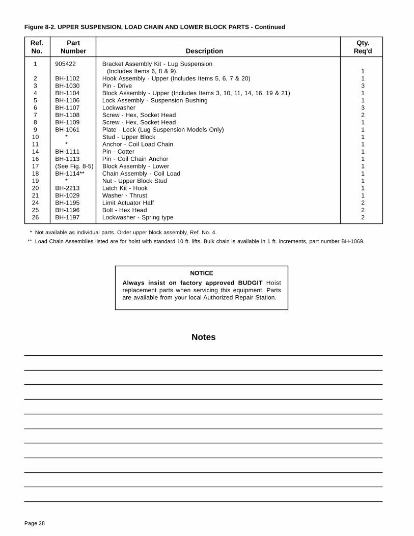
Page 28
Ref. Part Qty.No. Number Description Req’d
1 905422 Bracket Assembly Kit - Lug Suspension(Includes Items 6, 8 & 9). 1
2 BH-1102 Hook Assembly - Upper (Includes Items 5, 6, 7 & 20) 13 BH-1030 Pin - Drive 34 BH-1104 Block Assembly - Upper (Includes Items 3, 10, 11, 14, 16, 19 & 21) 15 BH-1106 Lock Assembly - Suspension Bushing 16 BH-1107 Lockwasher 37 BH-1108 Screw - Hex, Socket Head 28 BH-1109 Screw - Hex, Socket Head 19 BH-1061 Plate - Lock (Lug Suspension Models Only) 1
10 * Stud - Upper Block 111 * Anchor - Coil Load Chain 114 BH-1111 Pin - Cotter 116 BH-1113 Pin - Coil Chain Anchor 117 (See Fig. 8-5) Block Assembly - Lower 118 BH-1114** Chain Assembly - Coil Load 119 * Nut - Upper Block Stud 120 BH-2213 Latch Kit - Hook 121 BH-1029 Washer - Thrust 124 BH-1195 Limit Actuator Half 225 BH-1196 Bolt - Hex Head 226 BH-1197 Lockwasher - Spring type 2
Figure 8-2. UPPER SUSPENSION, LOAD CHAIN AND LOWER BLOCK PARTS - Continued
* Not available as individual parts. Order upper block assembly, Ref. No. 4.
** Load Chain Assemblies listed are for hoist with standard 10 ft. lifts. Bulk chain is available in 1 ft. increments, part number BH-1069.
Notes
NOTICE
Always insist on factory approved BUDGIT Hoistreplacement parts when servicing this equipment. Partsare available from your local Authorized Repair Station.
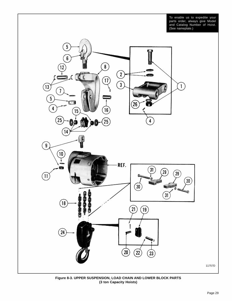
Page 29
Figure 8-3. UPPER SUSPENSION, LOAD CHAIN AND LOWER BLOCK PARTS(3 ton Capacity Hoists)
To enable us to expedite yourparts order, always give Modeland Catalog Number of Hoist.(See nameplate.)
11757D

Page 30
Ref. Part Qty.No. Number Description Req’d
1 BH-1131 Suspension Pin & Nut Assembly 12 BH-1132 Spherical Washer 1 Pr.3 905424 Suspension Lug Kit (Includes Items 1, 2, 4 & 26) 14 BH-1134 Pin Grooved 15 BH-1135 Hook/Latch & Nut (Includes Items 4, 6, & 7) 16 BH-2214 Latch Kit, Hook 17 BH-2217 Washer, Thrust 18 BH-1138 Hanger 19 BH-1139 Connecting Rod Assembly 1
10 BH-1029 Washer, Thrust 111 BH-1030 Pin, Grooved 112 BH-1142 Pin, Connection 113 BH-1143 Ring, Retaining 214 BH-1144 Sprocket & Bushing Assembly (Includes Item 15) 115 BH-1145 Bushing 216 BH-1146 Pin, Sprocket 117 BH-1147 Pin, Grooved 118 BH-1148** Chain Assembly, Coil Load 119 BH-1149 Link Connecting 120 BH-1150 Pin, Anchor 121 BH-1151 Pin, Cotter 122 BH-1152 Pin, Dowel 123 BH-1153 Ring, Retaining 124 (See Fig. 8-5) Block Assembly, Lower, Coil Chain 125 BH-2210 Washer, Thrust 226 BH-1154 Washer 129 BH-1195 Limit Actuator Half 430 BH-1196 Bolt - Hex Head 431 BH-1197 Lockwasher - Spring Type 4
** Load Chain Assemblies listed are for hoist with standard 10 ft. lifts. Bulk chain is available in 1 ft. increments, part numberBH-1069.
Figure 8-3. UPPER SUSPENSION, LOAD CHAIN AND LOWER BLOCK PARTS - Continued
Notes

Page 31
Ref. Part Qty.No. Number Description Req’d
2 BH-1202 Bearing Assembly - Ball, Motor Shaft 13 BH-1203 Ring - Retaining, Internal 14 BH-1220 Bearing Assembly - Needle, 5/8" I.D. 25 BH-1221 Washer - Thrust 5/8" I. D. 26 BH-1222 Ring - Snap, Brake Flange 17 BH-1219 Flange - Load Brake 18 BH-1218 Disc - Friction, Load Brake 29 BH-1223 Pawl & Ratchet Assembly - Load Brake (Includes item 10) 1
10 BH-1238 Bushing - Ratchet 111 Gear & Clutch Assembly - Load Brake 1
BH-1242* Standard Speed HoistBAH-1245* Reduced Speed Hoist
12 BH-1212 Spring - Load Brake (Plain - no color code) 113 BH-1216 Cam - Load Brake 114 BH-1239 Retainer - Spring, Load Brake 115 BH-1210 Key - Woodruff 216 Shaft & Integral Pinion - Load Brake 1
BH-1207 14 TeethBH-1208 23 Teeth
17 BH-1206 Washer-Thrust, 11/16" I.D. 118 BH-1205 Bearing -Thrust, Bronze 119 BH-1204 Bearing Assembly - Needle, 11/16" I.D. 120 BH-1214 Pin - Grooved 221 BH-1224 Ring - Snap, Intermediate Gear 122 Gear - Intermediate 1
BH-1225 74 TeethBH-1226 65 Teeth
23 BH-1236 Key - Woodruff 124 BH-1304 Shaft & Integral Pinion - Intermediate 125 BH-1237 Bearing Assembly - Needle, 11/16" I.D. (36 roller, greased retained) 126 BH-1305 Ring - Snap, Sprocket Gear 127 BH-1306 Gear - Sprocket 1
28** BH-1307 Spacer - Sprocket Gear 1
Figure 8-4. GEARING AND LOAD BRAKE PARTS
To enable us to expedite yourparts order, always give Modeland Catalog Number of Hoist.(See nameplate.)
11899A
(Continued on following page)

Page 32
Ref. Part Qty.No. Number Description Req’d
29 BH-1228 Screw - Filister Head Machine 430 BH-1229 Lockwasher - Spring Type 431 BH-1230 Plate - Retainer, Sprocket Bearing 1
32** BH-1231 Gasket - Ring, Sprocket Bearing 133 BH-1232 Bearing Assembly - Ball, Sprocket 134 BH-1308 Key - Woodruff, Sprocket 1
35** BH-1309 Sprocket - Coil Chain 137 BH-1235 Bearing Assembly - Ball, Sprocket 138 BH-1315 O-Ring 139 BH-1316 Seal Disk 140 BH-1317 Seal - Oil 1
* This gear and clutch assembly should not be field disassembled. Replace assembly only as clutch pressure is preset at factorybased on hoist capacity.
** On later model hoists; Ref. No. 28 is not used, Ref. No. 32 is replaced by Ref. Nos. 38, 39 and 40 and BH-1309 is replaced byBH-1312.
Figure 8-4. GEARING AND LOAD BRAKE PARTS - (continued)
Notes

Page 33
Figure 8-5. 2 & 3 TON LOWER BLOCK ASSEMBLIES
To enable us to expedite yourparts order, always give Modeland Catalog Number of Hoist.(See nameplate.)
12439
Quantity Required
Ref. PartNo. Number Description 2 Ton 3 Ton
BH-2219 Block Assembly - Lower Complete 1 -BH-2218 Block Assembly - Lower Complete - 1
1 BH-2202 Guide - Center 1 12 BH-2203 Lock - Sprocket Pin 1 13 BH-2204 Sprocket - Coil Chain 1 14 BH-2205 Bushing - Sprocket 1 15 BH-2206 Screw - Fillister Head, Self locking 1 16 BH-2207 Pin - Sprocket 1 17 BH-2208 Fitting - Hydraulic Drive 1 19 BH-2210 Washer, Thrust 1 1
10 BH-2211 Body Assembly - Lower Block - 111 BH-2212 Hook/Latch & Nut (Includes Items 12, 13 & 15) - 112 BH-2213 Latch Kit, Hook 1 -
BH-2214 Latch Kit, Hook - 113 BH-2215 Pin, Grooved - 114 BH-2216 Shroud - 115 BH-2217 Washer, Thrust - 116 BH-2220 Hook/Latch & Nut (Includes Items 12 & 17) 1 -17 BH-2221 Pin, Grooved 1 -18 BH-2222 Shield, Bearing 1 -19 BH-2223 Bearing Assembly - Needle, Thrust 1 -20 BH-2224 Washer, Thrust 2 -21 BH-2225 Body - Lower Block 1 -

Page 34
Ref. Part Qty.No. Number Description Req’d
1 BAH-5000 Limit Stop 12 BAH-5001 Support Pin - Limit Stop 13 BAH-5004 Ring - Retaining 14* BAH-5003 Hanger - Limit Stop 1
Figure 8-6. LIMIT STOP AND PARTS
To enable us to expedite yourparts order, always give Modeland Catalog Number of Hoist.(See nameplate.)
12440B
* On 2 and 3 line hoists only.
Notes

Page 35
Ref. Part Qty.No. Number Description Req’d
1 BAH-5100 Supply Head 12* BAH-5101 Valve Support 23* BAH-5102 Valve Guide Assembly 24 BAH-5103 Muffling Material 65 BAH-5104 Screen - Exhaust Valve 26 BAH-5105 Ring - Internal Retaining 27 BAH-5106 Screw - Self Tapping 28 BAH-5107 Adaptor Fitting 39 BAH-5108 Cap Screw - Hex Head 2
10 BAH-5109 Elbow - Reducing 111 BAH-5110 Nipple - Close Pipe 112 BAH-5111 Coupling Assembly 113 BAH-5112 Cap Screw - Hex Socket 214 BAH-5113 Lockwasher - Spring Type 215 BAH-5114 Gasket - Supply Head 116 BAH-5115 Muffler Body 117 BAH-5117 Gasket - Muffler 118 BAH-5117 Screen - Muffler 119 BAH-5118 Screw - Drive 220 BAH-5119 Muffler Cover 121 BAH-5120 Gasket - Muffler Cover 122 BAH-5121 Screw - Pan head 223* BAH-5123 Stem - Valve 224* BAH-5124 Spring - Valve 225* BAH-5125 Sleeve - Valve 226 BAH-5126 Screen - Muffler 1
Figure 8-7. SUPPLY HEAD AND MUFFLER PARTS
To enable us to expedite yourparts order, always give Modeland Catalog Number of Hoist.(See nameplate.)
12441A
* Reference Numbers 23, 24, and 25 replace Reference Numbers 2 and 3 used on earlier model hoists.

Page 36
Ref. Part Qty.No. Number Description Req’d
BAH-5200 Air Motor Assembly 11 BAH-5201 Rotor and Shaft Assembly 12 BAH-5202 Vane 83 BAH-5203 Spring - Vane 84 BAH-5204 Push Pin 45 BAH-5205 Body -Air Motor 16 BAH-5206 Pin - Dowel 47 BAH-5207 Gasket - Body 28 BAH-5208 End Plate - Drive End 19 BAH-5209 Bearing - Drive End 1
10 BAH-5210 Shaft Seal 111 BAH-5211 Seal Adaptor 112 BAH-5212 Ring - Retaining 113 BAH-5213 Cap Screw - Hex Socket 414 BAH-5214 Lockwasher - Spring Type 415 BAH-5215 End Plate - Dead End 116 BAH-5216 Bearing - Dead End 117 BAH-5217 Gasket - End Cap 118 BAH-5218 End Cap - Dead End 1
BAH-5219 End Plate Puller Tool (Not Shown) -19 BAH-5220 Screw 320 BAH-5221 Screw 621 BAH-5222 Screw 6
Figure 8-8. AIR MOTOR PARTS
To enable us to expedite yourparts order, always give Modeland Catalog Number of Hoist.(See nameplate.)
12442A

Page 37
Ref. Part Qty.No. Number Description Req’d
1 BAH-5300 Cap Screw - Hex Head 12 BAH-5301 Washer 13 BAH-5302 Thimble - Wire Rope 14 BAH-5303 Set Screw 15 BAH-5304 Clip - Wire rope 26 BAH-5305 Cable - Strain Relief (Specify length Required)
7 ft. for 10 ft. Lift 112 ft. for 15 ft. Lift 117 ft. for 20 ft. Lift 1
7 BAH-5306 Sleeve - Pressed 18 Hose Assembly - Down
BAH-5307 For 10 ft. Lift 1BAH-5308 For 15 ft. Lift 1BAH-5309 For 20 ft. Lift 1
9 Hose Assembly - UPBAH-5310 For 10 ft. Lift 1BAH-5311 For 15 ft. Lift 1BAH-5312 For 20 ft. Lift 1
10 Hose Assembly - SupplyBAH-5313 For 10 ft. Lift 1BAH-5314 For 15 ft. Lift 1BAH-5315 For 20 ft. Lift 1
11 BAH-5316 Tie - Cable 212 BAH-5317 Adaptor Fitting 313 BAH-5318 Pendant Throttle Handle Assembly - Complete (Includes Ref. Nos. 14 through 20
plus handle) 114 BAH-5319 Pin - Throttle Lever 115 BAH-5320 Throttle Lever 216 BAH-5321 Valve - Throttle 217 BAH-5322 Ring - Throttle Valve Seal 4
Figure 8-9. PENDANT THROTTLE CONTROL PARTS
To enable us to expedite yourparts order, always give Modeland Catalog Number of Hoist.(See nameplate.)
12443

Page 38
Fig. Ref. Part Corrision Resistant Spark ResistantNo. No. Number Description 1 Ton 2 Ton 3 Ton ½ Ton 1 Ton 2 Ton
8-1 1 BAH-5400 Hook Assembly-Upper with Latch - - 1 - -11 BAH-5401 Cover - Counterweighted - - - 1 - -
BAH-5402 Cover - Counterweighted - - - - 1 -BAH-5403 Cover - Counterweighted - - - - - 1
24 BAH-5430 Guide Assembly - Coil Load Chain - - - 1 1 125 BAH-5404 Chain Assembly - Coil, Load 1 - - - - -
BAH-5404 Chain Assembly - Coil, Load - - - 1 - -30 BAH-5406 Block Assembly - Lower - - - 1 - -32 BAH-5407 Body - Lower Block - - - 1 - -33 BAH-5408 Hook, Nut and Latch Assembly
- Lower Block - - - 1 - -34 BAH-5409 Latch Kit - Hook, Lower - - - 1 - -51 BAH-5410 Latch Kit - Hook Upper - - - 1 - -
8-2 2 BAH-5411 Hook Assembly-Upper with Latch - - - - 1 -18 BAH-5412 Chain Assembly - Coil, Load - 1 - - - -
BAH-5413 Chain Assembly - Coil, Load - - - - 1 -20 BAH-5414 Latch Kit - Hook, Upper - - - - 1 -
8-3 5 BAH-5415 Hook Assembly - Upper with Latch - - - - 118 BAH-5417 Chain Assembly - Coil, Load - - 1 - - -
BAH-5418 Chain Assembly - Coil, Load - - - - - 18-4 11 BAH-5429* Gear & Clutch Assembly
- Load Brake - - - 1 1 135 BAH-5419 Sprocket - Coil Chain - - - 1 1 1
8-5 - BAH-5420 Block Assembly - Lower Complete - - - - 1 -- BAH-5421 Block Assembly - Lower Complete - - - - - 1
10 BAH-5422 Body Assembly - Lower Block - - - - - 111 BAH-5423 Hook/Latch & Nut - - - - - 112 BAH-5424 Latch Kit - Hook, Lower - - - - 1 -16 BAH-5426 Hook/Latch & Nut - - - - 1 -21 BAH-5427 Body Assembly - Lower Block - - - - 1 -
8-6 1 BAH-5428 Limit Stop - - - 1 1 1
Figure 8-10. SPECIAL PARTS TABLE - CORROSION RESISTANT AND SPARK RESISTANT MODELS

Page 39

A. Seller warrants that its products and parts, when shipped, and itswork (including installation, construction and start-up), whenperformed, will meet applicable specifications, will be of good qualityand will be free from defects in material and workmanship. All claimsfor defective products or parts under this warranty must be made inwriting immediately upon discovery and in any event, within one (1)year from shipment of the applicable item unless Seller specificallyassumes installation, construction or start-up responsibility. All claimsfor defective products or parts when Seller specifically assumesinstallation, construction or start-up responsibility and all claims fordefective work must be made in writing immediately upon discoveryand in any event, within one (1) year from completion of the applicablework by Seller, provided; however, all claims for defective productsand parts made in writing no later than eighteen (18) months aftershipment. Defective items must be held for Seller’s inspection andreturned to the original f.o.b. point upon request. THE ‘FOREGOINGIS EXPRESSLY IN LIEU OF ALL OTHER WARRANTIESWHATSOEVER, EXPRESS, IMPLIED AND STATUTORY,INCLUDING, WITHOUT LIMITATION, THE IMPLIED WARRANTIESOF MERCHANTABILITY AND FITNESS.
WARRANTYWARRANTY AND LIMITATION OF REMEDY AND LIABILITY
B. Upon Buyer’s submission of a claim as provided above and itssubstantiation, Seller shall at its option either (i) repair or replace itsproduct, part or work at either the original f.o.b. point of delivery or atSeller’s authorized service station nearest Buyer or (ii) refund anequitable portion of the purchase price.
C. This warranty is contingent upon Buyer’s proper maintenance andcare of Seller’s products, and does not extend to normal wear andtear. Seller reserves the right to void warranty in event of Buyer’suse of inappropriate materials in the course of repair or maintenance,or if Seller’s products have been dismantled prior to submission toSeller for warranty inspection.
D. The foregoing is Seller’s only obligation and Buyer’s exclusiveremedy for breach of warranty and is Buyer’s exclusive remedyhereunder by way of breach of contract, tort, strict liability or otherwise.In no event shall Buyer be entitled to or Seller liable for incidental orconsequential damages. Any action for breach of this agreementmust be commenced within one (1) year after the cause of actionhas accrued.
Recommended Spare Partsfor Your Budgit Series 6000 Air Hoist
Certain parts of your hoist will, in time, require replacement under normal wear conditions.It is suggested that the following parts be purchased for your hoist as spares for future use.
One Set of Brake DiscsOne Set of GasketsOne Set of Oil Seals and "O" RingOne Set of Motor VanesOne Set of Motor SpringsOne Set of Motor Pins
Note: When ordering parts always furnish Model Number of Trolley.
Parts for your trolley are available from your local authorized BUDGIT repair station.For the location of your nearest repair station, write:
Yale�Lift-TechP.O. Box 769Muskegon, MI 49443-0769
Phone: 800 742-9269Fax: 800 742-9270


![[XLS] · Web viewHOIST HOIST EQUIPMENT ACTUATOR, MLG HOIST HOIST EQUIPMENT - ACTUATOR, MLG HOIST HOIST - CARDAN PIN HOIST HOIST-CARDAN PIN HOIST HOIST-DEVICE,FLAP TRACK 2-5 HOIST](https://static.fdocuments.net/doc/165x107/5b1fa5177f8b9aa64c8b4800/xls-web-viewhoist-hoist-equipment-actuator-mlg-hoist-hoist-equipment-actuator.jpg)