
Air Cylinder: Standard Type Double Acting, Single Rod 90...
23
Air Cylinder: Standard Type Double Acting, Single Rod ø10, ø16 90-CDJ2 Series M9BWL CDJ2 L 16 60 Bore size 10 16 10 mm 16 mm Mounting style Cylinder standard stroke (mm) Auto switch *For the applicable auto switch model, refer to the table below. Nil Without auto Switch Number of auto switches Head cover port location 90 10 16 15, 30, 45, 60, 75, 100, 125, 150 15, 30, 45, 60, 75, 100, 125, 150, 175, 200 *Manufacture of intermediate strokes at 1 mm intervals is possible. (Spacers are not used.) Applicable Auto Switch/Refer to pages 62 to 65 for further information on auto switches. *Additional symbols for auto switch: Lead wire length 3 m·················L Example: M9BWL With pre-wired connector··········SDPC M9BWSDPC *Order part numbers for auto switches alone are D-M9BWL-900, D-M9BWSDPC-900 and D-A90L-900. *Models D-M9BWVL-900 or M9BWVSDPC-900 cannot be mounted. *The auto switch is shipped together but not assembled. (Only auto switch mounting brackets are assembled before shipment.) *Refer to pages 66 to 68 for details on auto switch mounting brackets. Mounting Bracket Part No. Mounting bracket Foot bracket Flange bracket Bore size (mm) 6 10 16 90-CJ-L006B 90-CJ-F006B 90-CJ-L010B 90-CJ-F010B 90-CJ-L016B 90-CJ-F016B How to Order Built-in Magnet Cylinder Model Suffix the symbol “-B” (Band mounting style) to the end of part number for cylinder with auto switch. 90-CDJ2B16-60-B Example Band mounting style B L F D Basic style Axial foot style Rod side flange style Double clevis style (Except ø6) With auto switch With auto switch (Built-in magnet) Nil R Perpendicular to axis Axial ø10, ø16 Symbol Bore size (mm) *Double clevis is only available for being perpendicular to axis. Nil S n 2 pcs. 1 pc. “n” pcs. Type Special function Electrical entry Wiring (Output) Lead wire length (m) Auto switch model Load voltage DC AC Applicable load Pre-wired connector Grommet No 2-wire 100 V or less 24 V 12 V Relay, PLC IC circuit 3(L) SDPC M9BW A90 Indicator light Solid state switch Reed switch — Diagnostic indication (2-color indication) — — — Yes Series compatible with secondary batteries 90 Material restriction *Specifications and dimensios for the 90-series are the same as standard products. 12
Transcript of Air Cylinder: Standard Type Double Acting, Single Rod 90...

Air Cylinder: Standard TypeDouble Acting, Single Rod
ø10, ø1690-CDJ2 Series
M9BWLCDJ2 L 16 60
Bore size1016
10 mm
16 mm
Mounting style
Cylinder standard stroke (mm)
Auto switch
*For the applicable auto switch model, refer to the table below.
Nil Without auto Switch
Number of auto switches
Head cover port location
90
1016
15, 30, 45, 60, 75, 100, 125, 150
15, 30, 45, 60, 75, 100, 125, 150, 175, 200
*Manufacture of intermediate strokes at 1 mm intervals is possible. (Spacers are not used.)
Applicable Auto Switch/Refer to pages 62 to 65 for further information on auto switches.
*Additional symbols for auto switch: Lead wire length 3 m·················L Example: M9BWLWith pre-wired connector··········SDPC M9BWSDPC
*Order part numbers for auto switches alone are D-M9BWL-900, D-M9BWSDPC-900 and D-A90L-900.*Models D-M9BWVL-900 or M9BWVSDPC-900 cannot be mounted.*The auto switch is shipped together but not assembled. (Only auto switch mounting brackets are assembled before shipment.)*Refer to pages 66 to 68 for details on auto switch mounting brackets.
Mounting Bracket Part No.
Mounting bracket
Foot bracket
Flange bracket
Bore size (mm)
6 10 1690-CJ-L006B
90-CJ-F006B
90-CJ-L010B
90-CJ-F010B
90-CJ-L016B
90-CJ-F016B
How to Order
Built-in Magnet Cylinder ModelSuffix the symbol “-B” (Band mounting style) to the end of part number for cylinder with auto switch.
90-CDJ2B16-60-BExample Band mounting style
BLFD
Basic style
Axial foot style
Rod side flange style
Double clevis style (Except ø6)
With auto switch
With auto switch(Built-in magnet)
NilR
Perpendicular to axis
Axial
ø10, ø16Symbol
Bore size(mm)
*Double clevis is only available for being perpendicular to axis.
NilSn
2 pcs.
1 pc.
“n” pcs.
Type Special function Electricalentry
Wiring(Output)
Lead wire length (m)Auto switch model
Load voltage
DC ACApplicable load
Pre-wired connector
Grommet
No
2-wire
100 V or less
24 V 12 V Relay,PLC
IC circuit
3(L) SDPC
M9BW
A90
Indicatorlight
Solid
sta
te s
witc
hR
eed
sw
itch
—
Diagnostic indication(2-color indication) —
—
—Yes
Series compatible with secondary batteries
90 Material restriction
*Specifications and dimensios for the 90-series are the same as standard products.
12

Air Cylinder: Standard TypeDouble Acting, Single Rod
ø20, ø25, ø32, ø40, ø50CDG1 Series
CDG1 L N 25 100
Bore size2025324050
20 mm25 mm32 mm40 mm50 mm
M9BWL
Cylinder stroke (mm)
TypeN Rubber bumper
Mounting style
*91-series foot and rod side flange are assembled before shipment.
Number of auto switches
Auto switch
90Series compatible with
secondary batteries9091
Material restrictionWith lub-retainer
90-91-
Mounting Bracket Part No.Mountingbracket DescriptionMin.
orderBore size (mm)
FootFlangeTrunnion pinClevisPivot bracket
11111
2090-CG-L02090-CG-F02090-CG-T02090-CG-D02090-CG-020-24A
2590-CG-L02590-CG-F02590-CG-T02590-CG-D02590-CG-025-24A
3290-CG-L03290-CG-F03290-CG-T03290-CG-D03290-CG-032-24A
4090-CG-L04090-CG-F04090-CG-T04090-CG-D04090-CG-040-24A
5090-CG-L05090-CG-F05090-CG-T05090-CG-D05090-CG-050-24A
Foot x 2, Mounting bolt x 8Flange x 1, Mounting bolt x 4 Trunnion pin x 2, Trunnion bolt x 2, Flat washer x 2Clevis x 1, Mounting bolt x 4, Clevis pin x 1, Retaining ring x 2Pivot bracket x 1
Applicable Auto Switch/Refer to pages 62 to 65 for further information on auto switches.
How to Order
With auto switch
With auto switch(Built-in magnet)
BLFGUTD
Basic styleAxial foot style
Rod side flange styleHead side flange styleRod side trunnion styleHead side trunnion style
Clevis style
Built-in Magnet Cylinder ModelIf a built-in magnet cylinder without an auto switch is required, there is no need to enter the symbol for the auto switch.(Example) CDG1FN32-10090-
91-
NilSn
2 pcs.1 pc.
“n” pcs.
Nil Without auto switch
*For the applicable auto switch model, refer to the table below.
Bore size(mm)
2025324050
Standard stroke(1)
(mm)
25, 50, 75, 100, 125, 150, 200
25, 50, 75, 100, 125, 150, 200, 250, 300
Long stroke(2)
(mm)
Maximummanufacturable
stroke(mm)
201 to 350301 to 400301 to 450301 to 800
301 to 1200
1500
Note 1) Manufacture of intermediate strokes at 1 mm intervals is possible. (Spacers are not used.)
Note 2) Long stroke is compatible with the axial foot and rod side flange types. When other mounting brackets are used or the long stroke exceeds the limit, the allowable maximum stroke length is determined using the stroke selection table.
Type Special function Electricalentry
Wiring (Output)
Lead wire length (m)Auto switch model
Load voltage
DC ACApplicable load
Pre-wired connector
Grommet
No
2-wire
100 V or less
24 V 12 V Relay,PLC
ICcircuit
3(L) SDPC
M9BW
A90
Indicatorlight
Solid
sta
te s
witc
hR
eed
sw
itch
—
Diagnostic indication (2-color indication) —
—
—Yes
*Additional symbols for auto switch: Lead wire length 3 m·················L Example: M9BWLWith pre-wired connector··········SDPC M9BWSDPC
*Order part numbers for auto switches alone are D-M9BWL-900, D-M9BWSDPC-900 and D-A90L-900.*Models D-M9BWVL-900 or M9BWVSDPC-900 cannot be mounted.*The auto switch is shipped together but not assembled. (Only auto swich mounting brackets are assembled before shipment.)*Refer to pages 66 to 68 for details on auto switch mounting brackets.
*Specifications and dimensions for the 90-series are the same as standard products.
13
Dir
ecti
on
alC
on
tro
l Val
ves
Air
Pre
par
atio
nE
qu
ipm
ent
Vac
uu
mE
qu
ipm
ent
Det
ecti
on
Sw
itch
esA
uto
Sw
itch
esFl
ow C
ontr
olR
elat
ed P
rodu
cts
Air
Filte
rs/P
ress
ure
Con
trol
Equ
ipm
ent
Act
uat
ors
Air
Gri
pp
ers

CDA2 L 50 100 M9BWLNumber of auto switches
Mounting style
Bore size
Cylinder stroke (mm)
Auto switch
90
Air Cylinder: Standard TypeDouble Acting, Single Rod
ø40, ø50, ø63, ø80, ø100CDA2 Series90-
91-
Applicable Auto Switch/Refer to pages 62 to 65 for further information on auto switches.
**Models D-A90L-900 cannot be mounted on cylinders of ø50.
4091-CA2-L04
91-CA2-F04
91-CA2-C04
91-CA2-D04
5091-CA2-L05
91-CA2-F05
91-CA2-C05
91-CA2-D05
6391-CA2-L06
91-CA2-F06
91-CA2-C06
91-CA2-D06
8091-CA2-L08
91-CA2-F08
91-CA2-C08
91-CA2-D08
10091-CA2-L10
91-CA2-F10
91-CA2-C10
91-CA2-D10
How to Order
With auto switch
NilS3n
2 pcs.1 pc.3 pcs.
“n” pcs.
Nil Without auto switch
*Refer to the table below for the applicable auto switch model.
With auto switch(Built-in magnet)
Basic styleAxial foot style
Rod side flange styleHead side flange style
Single clevis styleDouble clevis style
Center trunnion style
BLFGCDT
40506380
100
40 mm50 mm63 mm80 mm
100 mm
Built-in Magnet Cylinder ModelIf a built-in magnet cylinder without an auto switch is required, there is no need to enter the symbol for the auto switch.(Example) CDA2L40-10090-
91-
25, 50, 75, 100, 125, 150, 175, 200, 250,300, 350, 400, 450, 500
25, 50, 75, 100, 125, 150, 175, 200, 250,300, 350, 400, 500, 600
25, 50, 75, 100, 125, 150, 175, 200, 250,300, 350, 400, 450, 500, 600, 700
40
50, 63
80, 100
*Intermediate strokes not listed above are produced upon receipt of order.
Type Special function Electricalentry
Wiring(Output)
Lead wire length (m)Auto switch modelLoad voltage
DC ACApplicable load
Pre-wired connector
Grommet
No
2-wire
100 V or less
24 V 12 V Relay,PLC
IC circuit
3(L) SDPCIndicator
light
Solid
sta
te s
witc
hR
eed
sw
itch
— —
Diagnostic indication(2-color indication) —
—
—Yes M9BWV M9BW
A90**
Perpendicular In-line
Mounting Bracket Part No.
Axial foot*
Flange
Single clevis
Double clevis**
Bore size (mm)
*When axial foot brackets are used, two pieces should be ordered for each cylinder.**Double clevis type is packed with clevis pin, flat washer and cotter pin.
*Additional symbols for auto switch: Lead wire length 3 m·················L Example: M9BWLWith pre-wired connector··········SDPC M9BWSDPC
*Order part numbers for auto switches alone are D-M9BW(V)L-900, D-M9BW(V)SDPC-900 and D-A90L-900.*The auto switch is shipped together but not assembled. (Only auto swich mounting brackets are assembled before shipment.)*Refer to pages 66 to 68 for details on auto switch mounting brackets.
*Specifications and dimensions for the 90-series are the same as standard products.
Series compatible with secondary batteries
9091
Material restrictionWith lub-retainer
14

CDUWith auto switch 16 3090 D M9BWL
Free Mount CylinderDouble Acting, Single Rod
ø10, ø16, ø20, ø25, ø32
1016202532
10 mm16 mm20 mm25 mm32 mm
CDU Series90-91-
Applicable Auto Switches/Refer to pages 62 to 65 for further information on auto switches.
How to Order
Built-in magnet
Bore size
Standard stroke (mm)ø6, ø10, ø16ø20, ø25, ø32
5, 10, 15, 20, 25, 305, 10, 15, 20, 25, 30, 40, 50
D Double acting
Action
Nil Without auto switch
*Refer to the table below for applicable auto switches.
Auto switch
Number of auto switchesNilS
2 pcs.1 pc.
Built-in Magnet Cylinder ModelIf a built-in magnet cylinder without an auto switch is required, there is no need to enter the symbol for the auto switch.(Example) CDU20-25D90-
91-
Type Special function Electricalentry
Wiring(Output)
Lead wire length (m)Auto switch modelLoad voltage
DC ACApplicable load
Pre-wired connector
Grommet
No
2-wire
100 V or less
24 V 12 VRelay,
PLC
ICcircuit
3(L) SDPCIndicator
light
Solid
sta
te s
witc
hR
eed
sw
itch
—
Diagnostic indication(2-color indication)
—
—
—Yes M9BWV
—
M9BW
A90
Perpendicular In-line
*Additional symbols for auto switch: Lead wire length 3 m·················L Example: M9BWLWith pre-wired connector··········SDPC M9BWSDPC
*Order part numbers for auto switches alone are D-M9BW(V)L-900, D-M9BW(V)SDPC-900 and D-A90L-900.*The auto switch is shipped together but not assembled.
*Specifications and dimensions for the 90-series are the same as standard products.
Series compatible with secondary batteries
9091
Material restrictionWith lub-retainer
15
Dir
ecti
on
alC
on
tro
l Val
ves
Air
Pre
par
atio
nE
qu
ipm
ent
Vac
uu
mE
qu
ipm
ent
Det
ecti
on
Sw
itch
esA
uto
Sw
itch
esFl
ow C
ontr
olR
elat
ed P
rodu
cts
Air
Filte
rs/P
ress
ure
Con
trol
Equ
ipm
ent
Act
uat
ors
Air
Gri
pp
ers

Free Mount Cylinder: Non-rotating Rod TypeDouble Acting, Single Rod
ø10, ø16, ø20, ø25, ø32CDUK Series90-
91-
CDUKWith auto switch 16 30 D30
1016202532
10 mm16 mm20 mm25 mm32 mm
M9BWL90
Applicable Auto Switches/Refer to pages 62 to 65 for further information on auto switches.
How to Order
Built-in magnet
Non-rotating rod type
Bore size
Standard stroke (mm)
Action
Auto switch
Number of auto switches
ø10, ø16ø20, ø25, ø32
5, 10, 15, 20, 25, 305, 10, 15, 20, 25, 30, 40, 50
D Double acting
*Refer to the table below for applicable auto switches.
Nil Without auto switch
NilS
2 pcs.1 pc.
Built-in Magnet Cylinder ModelIf a built-in magnet cylinder without an auto switch is required, there is no need to enter the symbol for the auto switch.(Example) CDUK20-25D90-
91-
Type Special function Electricalentry
Wiring(Output)
Lead wire length (m)Auto switch modelLoad voltage
DC ACApplicable load
Pre-wired connector
Grommet
No
2-wire
100 V or less
24 V 12 VRelay,
PLC
ICcircuit
3(L) SDPCIndicator
light
Solid
sta
te s
witc
hR
eed
sw
itch
—
Diagnostic indication(2-color indication)
—
—
—Yes M9BWV
—
M9BW
A90
Perpendicular In-line
*Additional symbols for auto switch: Lead wire length 3 m·················L Example: M9BWLWith pre-wired connector··········SDPC M9BWSDPC
*Order part numbers for auto switches alone are D-M9BW(V)L-900, D-M9BW(V)SDPC-900 and D-A90L-900.*The auto switch is shipped together but not assembled.
*Specifications and dimensions for the 90-series are the same as standard products.
Series compatible with secondary batteries
9091
Material restrictionWith lub-retainer
16

Compact Cylinder: Standard TypeDouble Acting, Single Rod
ø12, ø16, ø20, ø25
CDQSWith auto switch B D
Mounting style
Action
With auto switch(Built-in magnet)
M9BWLNumber of auto switches
Body option<Standard stroke> <Long stroke>
Auto switch
20 30
Bore size12 mm16 mm20 mm25 mm
12162025
Cylinder stroke (mm)
90
CDQS Series90-91-
Mounting Brackets for 91-series/Part No.Mounting Brackets for 90-series/Part No.Bore size
(mm) Foot (1) Flange
12162025
90-CQS-L01290-CQS-L01690-CQS-L02090-CQS-L025
90-CQS-F01290-CQS-F01690-CQS-F02090-CQS-F025
Double clevis
90-CQS-D01290-CQS-D01690-CQS-D02090-CQS-D025
Applicable Auto Switch/Refer to pages 62 to 65 for further information on auto switches.
How to Order
Through-hole/Both ends tapped common (Standard)
Foot styleRod side flange styleHead side flange style
Double clevis style
B
LFGD
*In the case of long strokes, use either ends tapped mounting or bracket mounting.
*Mounting brackets are shipped together, (but not assembled).
Bore size
12, 16
20
25
Standard stroke
5, 10, 15,20, 25, 30
5, 10, 15, 20, 25, 30, 35, 40, 45, 50
Long stroke
35, 40, 45, 50, 75, 100,125, 150, 175, 200
75, 100, 125, 150, 175, 200
75, 100, 125, 150, 175, 200, 250, 300
Double actingD
StandardWith rubber bumperRod end male thread
NilCM
*Combination of body options is available.
With rubber bumperRod end female thread (Standard)
With rubber bumperRod end male thread
C
CM
*Rubber bumper is standard equipment for long stroke type.
Nil Without auto switch* Refer to the table below for the
applicable auto switch model.
2 pcs.1 pc.
“n” pcs.
NilSn
Built-in Magnet Cylinder ModelIf a built-in magnet cylinder without an auto switch is required, there is no need to enter the symbol for the auto switch.(Example) CDQSL25-30D90-
91-
Type Special function Electricalentry
Wiring(Output)
Lead wire length (m)Auto switch modelLoad voltage
DC ACApplicable load
Pre-wired connector
Grommet
No
2-wire
100 V or less
24 V 12 V Relay, PLC
ICcircuit
3(L) SDPCIndicator
light
Solid
sta
te s
witc
hR
eed
sw
itch
—
Diagnostic indication(2-color indication) —
—
—Yes M9BWV
—
M9BW
A90
Perpendicular In-line
12162025
91-CQS-L01291-CQS-L01691-CQS-L02091-CQS-L025
91-CQS-F01291-CQS-F01691-CQS-F02091-CQS-F025
90-CQS-D01290-CQS-D01690-CQS-D02090-CQS-D025
Bore size(mm) Foot (1) Flange Double clevis
Note1) When ordering foot bracket, order 2 pieces per cylinder.Note2) Parts belonging to each bracket are as follows.
Foot or Flange style: Body mounting boltDouble clevis style: Clevis pin, Type C snap ring for axis, Body mounting bolt
*Additional symbols for auto switch: Lead wire length 3 m·················L Example: M9BWLWith pre-wired connector··········SDPC M9BWSDPC
*Order part numbers for auto switches alone are D-M9BW(V)L-900, D-M9BW(V)SDPC-900 and D-A90L-900.*The auto switch is shipped together but not assembled.Note) Auto switches of models D-M9BWVL-900 or M9BWVSDPC-900 cannot be mounted on the port depending on cylinder stroke and fitting size. Consult SMC.
*Specifications and dimensions for the 90-series are the same as standard products.
Series compatible with secondary batteries
9091
Material restrictionWith lub-retainer
17
Dir
ecti
on
alC
on
tro
l Val
ves
Air
Pre
par
atio
nE
qu
ipm
ent
Vac
uu
mE
qu
ipm
ent
Det
ecti
on
Sw
itch
esA
uto
Sw
itch
esFl
ow C
ontr
olR
elat
ed P
rodu
cts
Air
Filte
rs/P
ress
ure
Con
trol
Equ
ipm
ent
Act
uat
ors
Air
Gri
pp
ers
ø12, ø16, ø20, ø25
How to Order
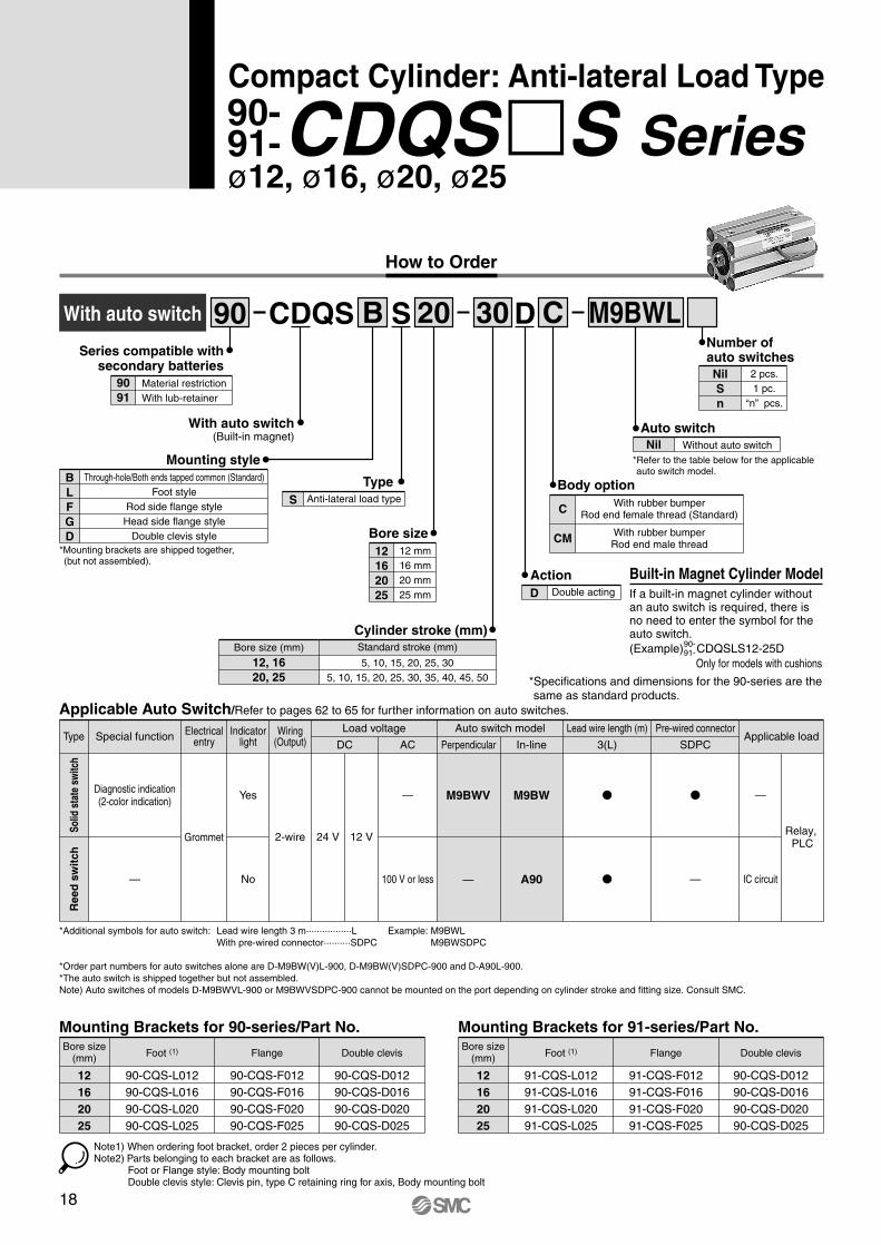
Compact Cylinder: Anti-lateral Load Type
CDQSWith auto switch B DS
Mounting style
Action
Type
With auto switch(Built-in magnet)
Number of auto switches
Body option
Auto switch
20 30
Bore size12 mm16 mm20 mm25 mm
12162025
C
Cylinder stroke (mm)
M9BWL90
CDQS�S Series90-91-
Mounting Brackets for 91-series/Part No.Mounting Brackets for 90-series/Part No.Bore size
(mm) Foot (1) Flange
12162025
90-CQS-L01290-CQS-L01690-CQS-L02090-CQS-L025
90-CQS-F01290-CQS-F01690-CQS-F02090-CQS-F025
Double clevis
90-CQS-D01290-CQS-D01690-CQS-D02090-CQS-D025
Applicable Auto Switch/Refer to pages 62 to 65 for further information on auto switches.
Through-hole/Both ends tapped common (Standard)Foot style
Rod side flange styleHead side flange style
Double clevis style
BLFGD
*Mounting brackets are shipped together, (but not assembled).
Anti-lateral load typeS
Standard stroke (mm)
5, 10, 15, 20, 25, 305, 10, 15, 20, 25, 30, 35, 40, 45, 50
Bore size (mm)
12, 1620, 25
Double actingD
With rubber bumperRod end female thread (Standard)
With rubber bumperRod end male thread
C
CM
Nil Without auto switch*Refer to the table below for the applicable auto switch model.
2 pcs.1 pc.
“n” pcs.
NilSn
Built-in Magnet Cylinder ModelIf a built-in magnet cylinder without an auto switch is required, there is no need to enter the symbol for the auto switch.(Example) CDQSLS12-25D
Only for models with cushions
90-91-
Type Special function Electricalentry
Wiring(Output)
Lead wire length (m)Auto switch modelLoad voltage
DC ACApplicable load
Pre-wired connector
Grommet
No
2-wire
100 V or less
24 V 12 V Relay, PLC
IC circuit
3(L) SDPCIndicator
light
Solid
sta
te s
witc
hR
eed
sw
itch
—
Diagnostic indication(2-color indication) —
—
—Yes M9BWV
—
M9BW
A90
Perpendicular In-line
12162025
91-CQS-L01291-CQS-L01691-CQS-L02091-CQS-L025
91-CQS-F01291-CQS-F01691-CQS-F02091-CQS-F025
90-CQS-D01290-CQS-D01690-CQS-D02090-CQS-D025
Bore size(mm) Foot (1) Flange Double clevis
Note1) When ordering foot bracket, order 2 pieces per cylinder.Note2) Parts belonging to each bracket are as follows.
Foot or Flange style: Body mounting boltDouble clevis style: Clevis pin, type C retaining ring for axis, Body mounting bolt
*Additional symbols for auto switch: Lead wire length 3 m·················L Example: M9BWLWith pre-wired connector··········SDPC M9BWSDPC
*Order part numbers for auto switches alone are D-M9BW(V)L-900, D-M9BW(V)SDPC-900 and D-A90L-900.*The auto switch is shipped together but not assembled.Note) Auto switches of models D-M9BWVL-900 or M9BWVSDPC-900 cannot be mounted on the port depending on cylinder stroke and fitting size. Consult SMC.
*Specifications and dimensions for the 90-series are the same as standard products.
Series compatible with secondary batteries
9091
Material restrictionWith lub-retainer
18
How to Order
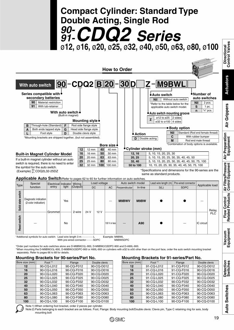
3020BCDQ2
Cylinder stroke (mm)
DWith auto switch M9BWL
Bore size1216202532
12 mm16 mm20 mm25 mm32 mm
40 mm50 mm63 mm80 mm
100 mm
40 50 63 80100
Number of auto switches
90
CDQ2 Series90-91-
90-91-
ø12, ø16, ø20, ø25, ø32, ø40, ø50, ø63, ø80, ø100
Mounting Brackets for 90-series/Part No.Bore size (mm) Foot (1) Flange
121620253240506380100
90-CQ-L01290-CQ-L01690-CQ-L02090-CQ-L02590-CQ-L03290-CQ-L04090-CQ-L05090-CQ-L06390-CQ-L08090-CQ-L100
90-CQ-F01290-CQ-F01690-CQ-F02090-CQ-F02590-CQ-F03290-CQ-F04090-CQ-F05090-CQ-F06390-CQ-F08090-CQ-F100
Double clevis90-CQ-D01290-CQ-D01690-CQ-D02090-CQ-D02590-CQ-D03290-CQ-D04090-CQ-D05090-CQ-D06390-CQ-D08090-CQ-D100
Mounting Brackets for 91-series/Part No.Bore size (mm) Foot (1) Flange
121620253240506380100
91-CQ-L01291-CQ-L01691-CQ-L02091-CQ-L02590-CQ-L03290-CQ-L04090-CQ-L05090-CQ-L06390-CQ-L08090-CQ-L100
91-CQ-F01291-CQ-F01691-CQ-F02091-CQ-F02590-CQ-F03290-CQ-F04090-CQ-F05090-CQ-F06390-CQ-F08090-CQ-F100
Double clevis90-CQ-D01290-CQ-D01690-CQ-D02090-CQ-D02590-CQ-D03290-CQ-D04090-CQ-D05090-CQ-D06390-CQ-D08090-CQ-D100
Note 1) When ordering foot bracket, order 2 pieces per cylinder.Note 2) Parts belonging to each bracket are as follows. Foot, Flange: Body mounting bolt/Double clevis: Clevis pin, Type C retaining ring for axis, body
mounting bolt
12, 1620, 2532, 40
50 to 100
5, 10, 15, 20, 25, 305, 10, 15, 20, 25, 30, 35, 40, 45, 505, 10, 15, 20, 25, 30, 35, 40, 45, 50, 75, 10010, 15, 20, 25, 30, 35, 40, 45, 50, 75, 100
Applicable Auto Switch/Refer to pages 62 to 65 for further information on auto switches.
Type
Ree
d sw
itch
Solid
sta
te s
witc
h
Specialfunction
Electricalentry
Wiring(Output)
Lead wire length (m)Auto switch modelLoad voltage
DC Perpendicular In-lineACApplicable load
Pre-wired connector
Diagnostic indication(2-color indication)
Grommet
Yes
No
2-wire
—
— 100 V or less
24 V 12 VRelay,PLC
—
IC circuit
3(L) SDPC
M9BWV M9BW
A90
Indicatorlight
Z
Auto switch mounting groove
Zø12 to ø25
ø32 to ø1002 sides4 sides
Compact Cylinder: Standard TypeDouble Acting, Single Rod
With auto switch(Built-in magnet)
BAL
FGD
Mounting styleThrough-hole (Standard)Both ends tapped style
Foot style
Rod side flange styleHead side flange style
Double clevis style
*Mounting brackets are shipped together, (but not assembled).
Built-in Magnet Cylinder ModelIf a built-in magnet cylinder without an auto switch is required, there is no need to enter the symbol for the auto switch.(Example) CDQ2L32-25DZ
ActionD Double acting
NilCM
Body option
*Combination of body options is available.
Standard (Rod end female thread)With rubber bumper Rod end male thread
Auto switchNil Without auto switch
*Refer to the table below for the applicable auto switch model.
NilSn
2 pcs.1 pc.
“n” pcs.
——
*Additional symbols for auto switch: Lead wire length 3 m·················L Example: M9BWLWith pre-wired connector··········SDPC M9BWSDPC
*Order part numbers for auto switches alone are D-M9BW(V)L-900, D-M9BW(V)SDPC-900 and D-A90L-900.*When mounting the D-M9BW(V)L-900, D-M9BW(V)SDPC-900 or A90L-900 on cylinders with ø32 to ø50 other than on the port face, order the auto switch mounting bracket separately. Refer to pages 66 to 68 for details.
*Specifications and dimensions for the 90-series are the same as standard products.
Series compatible with secondary batteries
9091
Material restrictionWith lub-retainer
19
Dir
ecti
on
alC
on
tro
l Val
ves
Air
Pre
par
atio
nE
qu
ipm
ent
Vac
uu
mE
qu
ipm
ent
Det
ecti
on
Sw
itch
esA
uto
Sw
itch
esFl
ow C
ontr
olR
elat
ed P
rodu
cts
Air
Filte
rs/P
ress
ure
Con
trol
Equ
ipm
ent
Act
uat
ors
Air
Gri
pp
ers

Auto switch mounting groove
Zø12 to ø25
ø32 to ø1002 sides4 sidesCylinder stroke (mm)
32, 40, 5063, 80, 100
125, 150, 175200, 250, 300
How to Order
With auto switch CDQ2
Bore size
20032 DCA
324050
32 mm40 mm50 mm
6380
100
63 mm80 mm
100 mm
90
ø32, ø40, ø50, ø63, ø80 ø100CDQ2 Series90-
91-
90-91-
Mounting Brackets for 90- and 91-series/Part No.Bore size (mm) Foot (1) Flange
3240506380100
90-CQ-L03290-CQ-L04090-CQ-L05090-CQ-L06390-CQ-L08090-CQ-L100
90-CQ-F03290-CQ-F04090-CQ-F05090-CQ-F06390-CQ-F08090-CQ-F100
Double clevis90-CQ-D03290-CQ-D04090-CQ-D05090-CQ-D06390-CQ-D08090-CQ-D100
Note 1) When ordering foot bracket, order 2 pieces per cylinder.Note 2) Parts belonging to each bracket are as follows.
Foot or Flange style: Body mounting bolt, Double clevis/Clevis pin, Type C retaining ring for axis, Body mounting bolt
M9BWLZ
Compact Cylinder: Long Stroke TypeDouble Acting, Single Rod
With auto switch(Built-in magnet)
ALFGD
Mounting styleBoth ends tapped style
Foot styleRod side flange styleHead side flange style
Double clevis style
*Mounting brackets are shipped together, (but not assembled).
Built-in Magnet Cylinder ModelIf a built-in magnet cylinder without an auto switch is required, there is no need to enter the symbol for the auto switch.(Example) CDQ2L40-200DCZ
ActionD Double acting
CCushion
Rubber bumper
NilM
Body optionStandard (Rod end female thread)
Rod end male thread
Auto switchNil Without auto switch
*Refer to the table below for the applicable auto switch model.
Number of autoswitchesNilSn
2 pcs.1 pc.
“n” pcs.
Applicable Auto Switch/Refer to pages 62 to 65 for further information on auto switches.
Type
Ree
d sw
itch
Solid
sta
te s
witc
h
Specialfunction
Electricalentry
Wiring(Output)
Lead wire length (m)Auto switch modelLoad voltage
DC Perpendicular In-lineACApplicable load
Pre-wired connector
Diagnostic indication(2-color indication)
Grommet
Yes
No
2-wire
—
— 100 V or less
24 V 12 VRelay,PLC
—
IC circuit
3(L) SDPC
M9BWV M9BW
A90
Indicatorlight
——
*Additional symbols for auto switch: Lead wire length 3 m·················L Example: M9BWLWith pre-wired connector··········SDPC M9BWSDPC
*Order part numbers for auto switches alone are D-M9BW(V)L-900, D-M9BW(V)SDPC-900 and D-A90L-900.*When mounting the D-M9BW(V)L-900, D-M9BW(V)SDPC-900 or A90L-900 on cylinders with ø32 to ø50 other than on the port face, order the auto switch mounting bracket separately. Refer to pages 66 to 68 for details.
*Specifications and dimensions for the 90-series are the same as standard products.
Series compatible with secondary batteries
9091
Material restrictionWith lub-retainer
20

How to Order
MY1BBasic type
Cylinder stroke (mm)
20 mm25 mm32 mm40 mm50 mm63 mm
Bore size (mm)202532405063
Basic type
M9BWL20 300
Stroke adjusting unitWithout adjusting unit
With low load shock absorber + Adjusting boltWith high load shock absorber + Adjusting bolt
With one L unit and one H unit each
NilLH
LH
90
ø20, ø25, ø32, ø40, ø50, ø63MY1B Series90-
91-
Applicable Auto Switch/Refer to pages 62 to 65 for further information on auto switches.
Type Special function Electricalentry
Wiring(Output)
Lead wire length (m)Auto switch modelLoad voltage
DC Perpendicular In-lineACApplicable load
Pre-wired connector
Diagnostic indication(2-color indication)
Grommet
Yes
No
2-wire
100 V or less
24 V 12 V Relay,PLC
IC circuit
3(L) SDPC
M9BWV**[Y7BWV]
— Z80
M9BW**[Y7BW]
Indicatorlight
20, 25, 32, 4050, 63
100, 200, 300, 400, 500, 600, 700800, 900, 1000, 1200, 1400, 16001800, 2000
Mechanically Jointed Rodless CylinderBasic Type
PipingStandard type
Centralized piping typeNilG
Both sidesOne side
Suffix for stroke adjusting unitNilS
Note) “S” is applicable for stroke adjusting units L and H.
Auto switchNil Without auto switch (Built-in magnet)
Applicable auto switches vary depending on the bore size. Select an applicable one referring to the table below.
2 pcs.1 pc.
“n” pcs.
Number of auto switchesNilSn
Solid
sta
te s
witc
hR
eed
sw
itch
—
—
—
—
*Additional symbols for auto switch: Lead wire length 3 m·················L Example: M9BWLWith pre-wired connector··········SDPC M9BWSDPC
*Order part numbers for auto switches alone are D-M9BW(V)L-900, D-M9BW(V)SDPC-900, D-Y7BW(V)L-900, D-Y7BW(V)SDPC-900 and D-Z80L-900.*The auto switch is shipped together but not assembled.*Refer to pages 66 to 68 for details on the auto switch mounting brackets.
*Specifications and dimensions for the 90-series are the same as standard products.
*The cylinder stroke is used every one millimeter up to the maximum stroke. When exceeding 2,000 mm, consult SMC.
No stroke adjustment units are used for ø50 and ø63.
Series compatible with secondary batteries
9091
Material restrictionWith lub-retainer
**Models D-M9BW(V)L-900 or D-M9BW(V)SDPC-900 cannot be mounted on cylinders of ø50.Select auto switches from those specified in brackets [ ].
21
Dir
ecti
on
alC
on
tro
l Val
ves
Air
Pre
par
atio
nE
qu
ipm
ent
Vac
uu
mE
qu
ipm
ent
Det
ecti
on
Sw
itch
esA
uto
Sw
itch
esFl
ow C
ontr
olR
elat
ed P
rodu
cts
Air
Filte
rs/P
ress
ure
Con
trol
Equ
ipm
ent
Act
uat
ors
Air
Gri
pp
ers

How to Order
MY1HLinear guide type
Cylinder stroke (mm)
Bore size16 mm20 mm25 mm32 mm40 mm
1620253240
Linear guide type
M9BWL25 300
Stroke adjusting unitWithout adjusting unit
With low load shock absorber + Adjusting boltWith high load shock absorber + Adjusting bolt
With one L unit and one H unit each
NilLH
LHNote) MY1H16 is not available with H unit.
90
ø16, ø20, ø25, ø32, ø40MY1H Series90-
91-
90-91-
16, 2025, 32, 40
50, 100, 150, 200250, 300, 350, 400450, 500, 550, 600
Applicable Auto Switch/Refer to pages 62 to 65 for further information on auto switches.
Type Special function Electricalentry
Wiring (Output)
Lead wire length (m)Auto switch modelLoad voltage
DC Perpendicular In-lineACApplicable load
Pre-wired connector
Diagnostic indication(2-color indication)
Grommet
Yes
No
2-wire
100 V or less
24 V 12 V Relay,PLC
IC circuit
3(L) SDPC
M9BWV M9BW
A90
Indicatorlight
Mechanically Jointed Rodless CylinderLinear Guide Type
PipingStandard type
Centralized piping typeNilG
Both endsOne end
Suffix for stroke adjusting unitNilS
Note) “S” is applicable for stroke adjusting units L and H.
Auto switchNil Without auto switch (Built-in magnet)
*Refer to the table below for the applicable auto switch model.
2 pcs.1 pc.
“n” pcs.
Number of auto switchesNilSn
Solid
sta
te s
witc
hR
eed
sw
itch
—
—
—
—
—
*Additional symbols for auto switch: Lead wire length 3 m·················L Example: M9BWLWith pre-wired connector··········SDPC M9BWSDPC
*Order part numbers for auto switches alone are D-M9BW(V)L-900, D-M9BW(V)SDPC-900 and D-A90L-900.*The auto switch is shipped together but not assembled.*Refer to pages 66 to 68 for details on the auto switch mounting brackets.
*Specifications and dimensions for the 90-series are the same as standard products.
Series compatible with secondary batteries
9091
Material restrictionWith lub-retainer
22

How to Order
MY2Linear Guide Type G
Stroke (mm)
Linear guide, Single axis
Guide typeH
LH 16 300
16 mm25 mm
Bore size1625
M9BWL90
ø16, ø25MY2H Series90-
91-
1625
50, 100, 150, 200, 250, 300, 350, 400, 450, 500, 550, 600
Applicable Auto Switch/Refer to pages 62 to 65 for the detailed specifications of auto switches.
Type Special function Electricalentry
Wiring(Output)
Lead wire length (m)Auto switch modelLoad voltage
DC Perpendicular In-lineACApplicable load
Pre-wired connector
Grommet
Yes
No
2-wire
100 Vor less
24 V 12 VRelay,PLC
ICcircuit
3(L) SDPC
M9BWV M9BW
A90
Indicatorlight
Mechanically Jointed Rodless CylinderLinear Guide Type
G Centralized piping type (Standard)
Piping
NilLH
LH
Without adjusting unitWith low load shock absorberWith high load shock absorber
With one L unit and one H unit each
Stroke adjusting unit
NilS
Both endsOne end
Stroke adjusting unit position
Note) “S” is applicable for stroke adjusting units L and H.
Auto switch typeNil Without auto switch (Built-in magnet)
*Refer to the table below for the applicable auto switch model.
NilSn
2 pcs.1 pc.
“n” pcs.
Number ofauto switches
Sol
id s
tate
sw
itch
Ree
d s
wit
ch
Diagnosticindication
2-colorindication
—
— — —
—
*Additional symbols for auto switch: Lead wire length 3 m·················L Example: M9BWLWith pre-wired connector··········SDPC M9BWSDPC
*Order part numbers for auto switches alone are D-M9BW(V)L-900, D-M9BW(V)SDPC-900 and D-A90L-900.*The auto switch is shipped together but not assembled.
*Specifications and dimensios for the 90-series are the same as standard products.
Series compatible with secondary batteries
9091
Material restrictionWith lub-retainer
23
Dir
ecti
on
alC
on
tro
l Val
ves
Air
Pre
par
atio
nE
qu
ipm
ent
Vac
uu
mE
qu
ipm
ent
Det
ecti
on
Sw
itch
esA
uto
Sw
itch
esFl
ow C
ontr
olR
elat
ed P
rodu
cts
Air
Filte
rs/P
ress
ure
Con
trol
Equ
ipm
ent
Act
uat
ors
Air
Gri
pp
ers
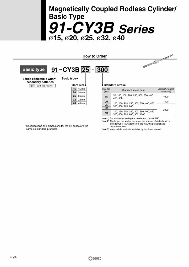
Basic type
Bore size
Basic type
1520253240
15 mm
20 mm
25 mm
32 mm
40 mm
Standard stroke
CY3B 25 300
How to Order
50, 100, 150, 200, 250, 300, 350, 400450, 500
1000
1500
2000
Bore size(mm) Standard stroke (mm) Maximum available
stroke (mm)
100, 150, 200, 250, 300, 350, 400, 450500, 600, 700, 800, 900, 1000
15
202532
40
100, 150, 200, 250, 300, 350, 400, 450500, 600, 700, 800
91
Magnetically Coupled Rodless Cylinder/ Basic Type
ø15, ø20, ø25, ø32, ø4091-CY3B Series
Note 1) For strokes exceeding the maximum, consult SMC.Note 2) The longer the stroke, the larger the amount of deflection in a
cylinder tube. Pay attention to the mounting bracket and clearance value.
Note 3) Intermediate stroke is available by the 1 mm interval.*Specifications and dimensions for the 91-series are the same as standard products.
Series compatible with secondary batteries
91 With lub-retainer
24A

How to Order
Magnetically Coupled Rodless Cylinder/ Direct Mount Type
ø15, ø20, ø25, ø32, ø40
CY3R
Cylinder stroke (mm)
15 mm20 mm25 mm32 mm40 mm
Bore size1520253240
Direct mount type
M9BWL25 300
*Refer to the table below for auto switch model numbers.
91
91-CY3R Series
Note 1) The longer the stroke, the larger the amount of deflection in a cylinder tube. Pay attention to the mounting bracket and clearance value.
Note 2) Intermediate stroke is available by the 1 mm interval.
Bore size(mm)
50, 100, 150, 200, 250, 300, 350400, 450, 500
100, 150, 200, 250, 300, 350, 400450, 500, 600, 700, 800, 900, 1000
15
202532
40
Standard stroke (mm) Max. stroke with switch (mm)
Max. stroke without switch (mm)
100, 150, 200, 250, 300, 350, 400450, 500, 600, 700, 800
1000
1500
2000
750
10001200
1500
Applicable Auto Switches /Refer to pages 62 to 65 for further information on auto switches.
Type Special functionElectrical
entryWiring
(output)Lead wire length (m)
Auto switch modelLoad voltage
DC ACApplicable load
Pre-wired connector
Diagnostic indication
(2-color display)
Grommet
Yes
No
2-wire
�
100 V or less
24 V 12 VRelay,PLC
�
IC circuit
3(L) SDPC
M9BW
A90
Indicatorlight
NilG
Standard type
Centralized piping type
Piping type
Number of auto switchesNilSn
2 pcs.
1 ps.
“n” pcs.
Auto switch typeNil Without auto switch (Built-in magnet)
Switch railNilN
With switch rail
Without switch rail
Note) A type with switch rail has built-in auto switch magnets.
�
So
lid s
tate
swit
chR
eed
switc
h
*Additional symbols for auto switch: Lead wire length 3 m·················L Example: M9BWLWith pre-wired connector··········SDPC M9BWSDPC
*Order part numbers for auto switches alone are D-M9BWL-900, D-M9BWSDPC-900 and D-A90L-900.*Models D-M9BWVL-900 or M9BWVSDPC-900 cannot be mounted.*The auto switch is shipped together but not assembled.*Refer to pages 66 to 68 for details on the auto switch mounting brackets.
*Specifications and dimensions for the 91-series are the same as standard products.
Series compatible with secondary batteries
91 With lub-retainer
�
25 A
Dir
ecti
on
alC
on
tro
l Val
ves
Air
Pre
par
atio
nE
qu
ipm
ent
Vac
uu
mE
qu
ipm
ent
Det
ecti
on
Sw
itch
esA
uto
Sw
itch
esFl
ow C
ontr
olR
elat
ed P
rodu
cts
Air
Filte
rs/P
ress
ure
Con
trol
Equ
ipm
ent
Act
uat
ors
Air
Gri
pp
ers
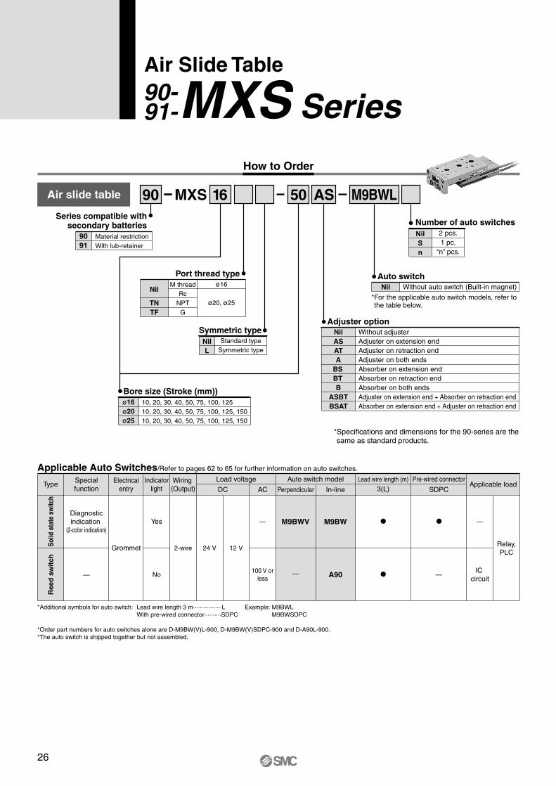
MXS SeriesAir Slide Table
M9BWLAir slide table
Adjuster option
How to Order
10, 20, 30, 40, 50, 75, 100, 12510, 20, 30, 40, 50, 75, 100, 125, 15010, 20, 30, 40, 50, 75, 100, 125, 150
ø16ø20ø25
Bore size (Stroke (mm))
MXS 16 50 AS
Port thread type
Nii
TNTF
M threadRc
NPTG
ø16
ø20, ø25
90
Applicable Auto Switches/Refer to pages 62 to 65 for further information on auto switches.
TypeSpecialfunction
Electricalentry
Lead wire length (m)Auto switch modelLoad voltage
DC Perpendicular In-lineACApplicable load
Pre-wired connector
Diagnosticindication
(2-color indication)
Grommet
Yes
No
2-wire
—
—
24 V 12 V
—
Relay,PLC
—
3(L) SDPC
M9BWV
—
M9BW
A90
Indicatorlight
90-91-
2 pcs.1 pc.
“n” pcs.
NilSn
Number of auto switches
Auto switchNil Without auto switch (Built-in magnet)
*For the applicable auto switch models, refer to the table below.
Without adjusterAdjuster on extension endAdjuster on retraction endAdjuster on both endsAbsorber on extension endAbsorber on retraction endAbsorber on both endsAdjuster on extension end + Absorber on retraction endAbsorber on extension end + Adjuster on retraction end
NilASATA
BS
BT
BASBTBSAT
Ree
d s
wit
chSo
lid s
tate
sw
itch
Wiring (Output)
IC circuit
100 V orless
NilL
Symmetric typeStandard type
Symmetric type
*Additional symbols for auto switch: Lead wire length 3 m·················L Example: M9BWLWith pre-wired connector··········SDPC M9BWSDPC
*Order part numbers for auto switches alone are D-M9BW(V)L-900, D-M9BW(V)SDPC-900 and D-A90L-900.*The auto switch is shipped together but not assembled.
*Specifications and dimensions for the 90-series are the same as standard products.
Series compatible with secondary batteries
9091
Material restrictionWith lub-retainer
26

How to Order
10, 20, 30, 40, 5010, 20, 30, 40, 50, 7510, 20, 30, 40, 50, 75, 10010, 20, 30, 40, 50, 75, 100, 12510, 20, 30, 40, 50, 75, 100, 125, 15010, 20, 30, 40, 50,7 5, 100, 125, 150
ø6ø8
ø12ø16ø20ø25
Bore size (Stroke mm)
MXQ 16 50 M9BWL
Number of auto switches
90
90-91-MXQ Seriesø6, ø8, ø12, ø16, ø20, ø25
Air Slide Table
Applicable Auto Switch/Refer to pages 62 to 65 for the detailed specifications of auto switches.
Type Specialfunction
Electricalentry
Wiring(Output)
Lead wire length (m)Auto switch modelLoad voltage
DC Perpendicular In-lineACApplicable
loadPre-wired connector
Diagnosticindication
(2-color indication)
Grommet
Yes
No
2-wire
—
100 V orless
24 V 12 V
—
IC circuit
3(L) SDPC
M9BWV
—
M9BW
A90
Indicatorlight
Adjuster optionNilASATA
BSBTB
CSCTC
ASBTASCTBSATBSCTCSATCSBT
Without adjusterExtension end adjusterRetraction end adjusterDouble end adjusterExtension end absorberRetraction end absorberDouble absorberExtension end metal stopperRetraction end metal stopperDouble metal stopperExtension end adjustor + Retraction end absorberExtension end adjustor + Retraction end metal stopperExtension end absorber + Retraction end adjusterExtension end absorber + Retraction end metal stopperExtension end metal stopper + Retraction end adjusterExtension end metal stopper + Retraction end absorber
AS
Port thread type
Nil
TNTF
M threadRc
NPTG
ø6 to ø16
ø20, ø25
2 pcs.1 pc.
“n” pcs.
NilSn
Auto switchNil Without auto switch (Built-in magnet)
*For the applicable auto switch model, refer to the table below.
*90- and 91-series MXQ6 products do not have shock absorbers.
Ree
d s
wit
chSo
lid s
tate
sw
itch
— —
Relay,PLC
NilL
Symmetric typeStandard type
Symmetric type
*Additional symbols for auto switch: Lead wire length 3 m·················L Example: M9BWLWith pre-wired connector··········SDPC M9BWSDPC
*Order part numbers for auto switches alone are D-M9BW(V)L-900, D-M9BW(V)SDPC-900 and D-A90L-900.*The auto switch is shipped together but not assembled.
*Specifications and dimensions for the 90-series are the same as standard products.
Series compatible with secondary batteries
9091
Material restrictionWith lub-retainer
27
Dir
ecti
on
alC
on
tro
l Val
ves
Air
Pre
par
atio
nE
qu
ipm
ent
Vac
uu
mE
qu
ipm
ent
Det
ecti
on
Sw
itch
esA
uto
Sw
itch
esFl
ow C
ontr
olR
elat
ed P
rodu
cts
Air
Filte
rs/P
ress
ure
Con
trol
Equ
ipm
ent
Act
uat
ors
Air
Gri
pp
ers

Compact Guide Cylinder
ø12, ø16, ø20, ø25, ø32, ø40, ø50, ø63
How to Order
MGPCompact Guide Cylinder M 25
Cylinder stroke (mm)12 mm16 mm20 mm25 mm
Bore size12162025
32 mm40 mm50 mm63 mm
32405063
Compact Guide Cylinder
M9BWL3090
MGP Series90-91-
25, 50, 75, 100, 125, 150, 175, 200, 250, 300, 350400
12, 16
20, 25
32 to 63
10, 20, 30, 40, 50, 75, 100, 125, 150, 175, 200, 250
20, 30, 40, 50, 75, 100, 125, 150, 175, 200, 250, 300350, 400
Applicable Auto Switch/Refer to pages 62 to 65 for further information on auto switches.
Type Specialfunction
Electricalentry
Wiring(Output)
Lead wire length (m)Auto switch modelLoad voltage
DC Perpendicular In-lineACApplicable load
Pre-wired connector
Diagnosticindication
(2-color indication)
Grommet
Yes
No
2-wire 24 V 12 VRelay,PLC
—
ICcircuit
3(L) SDPC
M9BWV
—
M9BW
A90
Indicatorlight
Minimum Operating Pressure for Products for 91-series SpecificationsBore size (mm) 12, 16, 20, 25
Minimum operating pressure 0.2MPa
32, 40, 50, 630.15MPa
Slide bearingBall bushing bearing
Bearing typeML
Number of auto switchesNilSn
2 pcs.1 pc.“n” pcs.
Auto switch
NilWithout auto switch
(Built-in magnet)
*For the applicable auto switch model,refer to the table below.
Ree
d s
wit
chSo
lid s
tate
sw
itch
— —
—
100 V orless
*Additional symbols for auto switch: Lead wire length 3 m·················L Example: M9BWLWith pre-wired connector··········SDPC M9BWSDPC
*Order part numbers for auto switches alone are D-M9BW(V)L-900, D-M9BW(V)SDPC-900 and D-A90L-900.*The auto switch is shipped together but not assembled.*Refer to pages 66 to 68 for details on the auto switch mounting brackets.
*Specifications and dimensions for the 90-series are the same as standard products.
Series compatible with secondary batteries
9091
Material restrictionWith lub-retainer
28

L M9BWLB 32
Guide Cylinder
MGG 100
Cylinder stroke (mm)
Bore size2025324050
20 mm
25 mm
32 mm
40 mm
50 mm
How to Order
Guide Cylinder
ø20, ø25, ø32, ø40, ø50
90
MGG Series90-91-
250, 300, 350, 400
350, 400, 450, 500
350, 400, 450, 500, 600, 700, 800, 900,1000
350, 400, 450, 500, 600, 700, 800
350, 400, 450, 500, 600
20
25
32
40
50
Bore size(mm)
75, 100, 125, 150, 200
Standard stroke (mm)
75, 100, 125, 150, 200
250, 300
Long stroke (mm)
*Intermediate strokes and short strokes other than the above are produced upon receipt of order.
Applicable Auto Switch/Refer to pages 62 to 65 for further information on auto switches.
TypeSpecialfunction
Electricalentry
Wiring (Output)
Lead wire length (m)Auto switch model
Load voltage
DC ACApplicable
loadPre-wired connector
Diagnosticindication
(2-color indication)
Grommet
Yes
2-wire
100 V orless
24 V 12 V
3(L) SDPC
M9BW
A90
Indicatorlight
L
Bearing typeBall bushing bearing
BF
Mounting styleBasic style
Front mounting flange style
Number of auto switchesNilSn
2 pcs.
1 pc.
“n” pcs.
Auto switch
*For the applicable auto switch model, refer to the table below.
Nil Without auto switch(Built-in magnet)
Ree
d sw
itch
Solid
sta
te s
witc
h
—
—
—
— No IC circuit
Relay,PLC
*Additional symbols for auto switch: Lead wire length 3 m·················L Example: M9BWLWith pre-wired connector··········SDPC M9BWSDPC
*Order part numbers for auto switches alone are D-M9BWL-900, D-M9BWSDPC-900 and D-A90L-900.*Models D-M9BWVL-900 or M9BWVSDPC-900 cannot be mounted.*The auto switch is shipped together but not assembled. (Only auto switch mounting brackets are assembled before shipment.)*Refer to pages 66 to 68 for details on the auto switch mounting brackets.
*Specifications and dimensions for the 90-series are the same as standard products.Specifications for the 91-series are the same as standard products.
Series compatible with secondary batteries
9091
Material restrictionWith lub-retainer
29
Dir
ecti
on
alC
on
tro
l Val
ves
Air
Pre
par
atio
nE
qu
ipm
ent
Vac
uu
mE
qu
ipm
ent
Det
ecti
on
Sw
itch
esA
uto
Sw
itch
esFl
ow C
ontr
olR
elat
ed P
rodu
cts
Air
Filte
rs/P
ress
ure
Con
trol
Equ
ipm
ent
Act
uat
ors
Air
Gri
pp
ers

How to Order
CDNGWith auto switch L N 32 D100 M9BWL
Nil Without auto switch
*For the applicable auto switch model, refer to the table below.
*Mounting brackets are shipped together, (but not assembled).
Locking directionD Both directions
Cylinder stroke (mm)
Bore size20253240
20 mm
25 mm
32 mm
40 mm(Built-in magnet)
With auto switchMounting style
BLFGUTD
Basic style
Axial foot style
Rod side flange style
Head side flange style
Rod side trunnion style
Head side trunnion style
Clevis style
Auto switch
Cushion typeN Rubber bumper
NilSn
2 pcs.
1 pc.
“n” pcs.
Number of auto switches
90Series compatible with
secondary batteries9091
Material restriction
With lub-retainer
Cylinder with LockDouble Acting, Single Rod
ø20, ø25, ø32, ø40CDNG Series90-
91-
Built-in Magnet Cylinder ModelIf a built-in magnet cylinder without an auto switch is required, there is no need to enter the symbol for the auto switch.(Example) CDNGLN40-100-D90-
91-
Bore size(mm)
20253240
Standard stroke (mm) (1) Max. manufacturablestroke (mm)
1500
25, 50, 75, 100, 125, 150, 200
25, 50, 75, 100, 125, 150, 200,250, 300
Long stroke(mm)
201 to 350
301 to 400
301 to 450
301 to 800
Note 1) Intermediate strokes other than the above are produced upon receipt of order. Spacers are not used for intermediate strokes.
Note 2) Long strokes are applicable to the axial foot style and rod side flange style.In the case of other mounting brackets or when long stroke limits are exceeded, the maximum useable stroke is determined by the stroke selection table (information edition).
Mounting Bracket Part No.
Axial foot *
Flange
Trunnion pin
Clevis **
Rod side pivot bracket
Head side pivot bracket
20
91-CNG-L020
91-CNG-F020
90-CG-T020
90-CG-D020
91-CNG-020-24
90-CG-020-24A
25
91-CNG-L025
91-CNG-F025
90-CG-T025
90-CG-D025
91-CNG-025-24
90-CG-025-24A
32
91-CNG-L032
91-CNG-F032
90-CG-T032
90-CG-D032
91-CNG-032-24
90-CG-032-24A
40
91-CNG-L040
91-CNG-F040
90-CG-T040
90-CG-D040
91-CNG-040-24
90-CG-040-24A
Bore size (mm)Mounting bracket
Applicable Auto Switch/Refer to pages 62 to 65 for further information on auto switches.
TypeSpecialfunction
Electricalentry
Wiring(Output)
Lead wire length (m)Auto switch model
Load voltage
DC ACApplicable load
Pre-wired connector
Diagnosticindication
(2-color indication)
Grommet
Yes
No
2-wire
100 Vor less
24 V 12 VRelay,PLC
3(L) SDPC
M9BW
A90
Indicatorlight
Ree
d s
wit
chS
olid
sta
tesw
itch
IC circuit
*When ordering foot bracket, order 2 pieces per cylinder.
**Clevis pin, retaining ring, and mounting bolt are shipped together with clevis style.
***Mounting bolts are included with the foot and flange styles.
—
—
—
—
*Specifications and dimensions for the 90-series are the same as standard products. Specifications for the 91-series are the same as standard products.
*Additional symbols for auto switch: Lead wire length 3 m················L Example: M9BWLWith pre-wired connector·········SDPC M9BWSDPC
*Order part numbers for auto switches alone are D-M9BWL-900, D-M9BWSDPC-900 and D-A90L-900.*Models D-M9BWVL-900 or M9BWVSDPC-900 cannot be mounted.*The auto switch is shipped together but not assembled. (Only auto switch mounting brackets are assembled before shipment.)*Refer to pages 66 to 68 for details on the auto switch mounting brackets.
30

How to Order
M9BWLNumber ofauto switchesNilSn
2 pcs. 1 pc. “n” pcs.
With auto switch(Built-in magnet)
Mounting styleBLFGCDT
Basic styleAxial foot style
Rod side flange styleHead side flange style
Single clevis styleDouble clevis style
Center trunnion style
With auto switch CDNA
Cylinder stroke (mm)
TypeN Non-lube
L N 50 100 D
*For the applicable auto switch model, refer to the table below.
Auto switchNil Without auto switch
Bore size40506380
100
40 mm50 mm63 mm80 mm
100 mm
90Series compatible with
secondary batteries
CDNA Series90-91-
Cylinder with LockDouble Acting, Single Rod
ø40, ø50, ø63, ø80, ø100
Bore size(mm)
40
50, 63
80, 100
Standard stroke (mm) (1) Long stroke(mm) (2)
1000
ø80:1000
ø100:
80025, 50, 75, 100, 125, 150, 175, 200, 250,300, 350, 400, 450, 500
25, 50, 75, 100, 125, 150, 175, 200, 250,300, 350, 400, 450, 500, 600
25, 50, 75, 100, 125, 150, 175, 200, 250,300, 350, 400, 450, 500, 600, 700
Note 1) Intermediate strokes other than the above are produced upon receipt of order. Spacers are not used for intermediate strokes.
Note 2) Long stroke applies to the axial foot style and the rod side flange style. When exceeding the stroke range for each bracket, determine the maximum strokes referring to the Selection Table (front matter 29 in Best Pneumatics No. 2).
Applicable Auto Switch/Refer to pages 62 to 65 for further information on auto switches.
Perpendicular In-line
M9BW
A90**
Mounting Bracket Part No.
Foot *
Flange
Single clevis
Double clevis **
Bore size (mm) 40
90-CA1-L04
90-CA1-F04
90-CA1-C04
90-CA1-D04
50
90-CA1-L05
90-CA1-F05
90-CA1-C05
90-CA1-D05
63
90-CA1-L06
90-CA1-F06
90-CA1-C06
90-CA1-D06
80
90-CA1-L08
90-CA1-F08
90-CA1-C08
90-CA1-D08
100
90-CA1-L10
90-CA1-F10
90-CA1-C10
90-CA1-D10
* When ordering foot bracket, order 2 pieces per cylinder.**Clevis pin, plain washer, and cotter pin are shipped together with
double clevis style.
Locking directionD Both directions
TypeSpecialfunction
Electricalentry
Wiring(Output)
Lead wire length (m)Auto switch modelLoad voltage
DC ACApplicable load
Pre-wired connector
Diagnosticindication
(2-color indication)
Grommet
Yes
No
2-wire
100 Vor less
24 V 12 VRelay,PLC
3(L) SDPCIndicator
light
Ree
d s
wit
chS
olid
sta
tesw
itch
IC circuit
M9BWV
Built-in Magnet Cylinder ModelIf a built-in magnet cylinder without an auto switch is required, there is no need to enter the symbol for the auto switch.(Example) CDNALN40-100-D90-
91-
—
—
— —
—
*Specifications and dimensions for the 90-series are the same as standard products. Specifications for the 91-series are the same as standard products.
*Additional symbols for auto switch: Lead wire length 3 m················L Example: M9BWL **Models D-A90L-900 cannot be mounted on cylinders of ø50.With pre-wired connector·········SDPC M9BWSDPC
*Order part numbers for auto switches alone are D-M9BW(V)L-900, D-M9BW(V)SDPC-900 and D-A90L-900.*The auto switch is shipped together but not assembled. (Only auto switch mounting brackets are assembled before shipment.)*Refer to pages 66 to 68 for details on the auto switch mounting brackets.
9091
Material restrictionWith lub-retainer
31
Dir
ecti
on
alC
on
tro
l Val
ves
Air
Pre
par
atio
nE
qu
ipm
ent
Vac
uu
mE
qu
ipm
ent
Det
ecti
on
Sw
itch
esA
uto
Sw
itch
esFl
ow C
ontr
olR
elat
ed P
rodu
cts
Air
Filte
rs/P
ress
ure
Con
trol
Equ
ipm
ent
Act
uat
ors
Air
Gri
pp
ers

How to Order
M9BWL3040
With auto switch(Built-in magnet)
BCDLQ
Cylinder stroke (mm)
FDWith auto switch
Auto switch
*For the applicable auto switch model, refer to the table below.
Nil Without auto switch
Locking directionFB
Extension lockingRetraction locking
ActionD Double acting
Bore size20253240506380
100
20 mm25 mm32 mm40 mm50 mm63 mm80 mm
100 mm
Body optionNilCM
CM
Standard (Rod end female thread)With rubber bumperRod end male thread
With rubber bumper, Rod end male thread
Mounting styleø20, ø25 ø32 to ø100
Built-in Magnet Cylinder Model
Number ofauto switches
NilSn
2 pcs. 1 pc.
“n” pcs.
90Series compatible with
secondary batteries9091
Material restrictionWith lub-retainer
Compact Cylinder with LockDouble Acting, Single Rod
ø20, ø25, ø32, ø40, ø50, ø63, ø80, ø100CDLQ Series90-
91-
90-91-
20, 2532, 40, 50, 63, 80, 100
5, 10, 15, 20, 25, 30, 35, 40, 45, 50
10, 15, 20, 25, 30, 35, 40, 45, 50, 75, 100
Mounting Bracket Part No.Bore size (mm) Foot (1) Flange
20253240
91-CLQ-L02091-CLQ-L02591-CLQ-L03291-CLQ-L040
91-CLQ-F02091-CLQ-F02591-CLQ-F03291-CLQ-F040
91-CLQ-D02091-CLQ-D02591-CLQ-D03291-CLQ-D040
506380100
91-CLQ-L05091-CLQ-L06391-CLQ-L08091-CLQ-L100
91-CLQ-F05091-CLQ-F06391-CLQ-F08091-CLQ-F100
91-CLQ-D05091-CLQ-D06391-CLQ-D08091-CLQ-D100
Double clevis (3) Bore size (mm) Foot (1) Flange Double clevis (3)
Note1) When ordering foot bracket, order 2 pieces per cylinder.Note2) Parts belonging to each bracket are as follows. Foot, Flange: Body mounting screws, Double clevis: Clevis pin, type C retaining ring for shaft, Body mounting screws, Flat
washer.Note3) Clevis pin and retaining ring are included with the double clevis style.
Applicable Auto Switch/Refer to pages 62 to 65 for detailed specifications of auto switches.
M9BW
A90
*Mounting bracket is shipped together, (but not assembled).
Through-hole/Both ends tapped common (Standard)
Foot styleRod side flange styleHead side flange style
Double clevis style
B
LFGD
Through-hole (Standard)Both ends tapped style
Foot styleRod side flange styleHead side flange styleDouble clevis style
BALFGD
Bore size (mm) Standard stroke (mm)
If a built-in magnet cylinder without an auto switch is required, there is no need to enter the symbol for the auto switch.(Example) CDLQL32-30D-B
M9BWV
Perpendicular In-lineType
Specialfunction
Electricalentry
Wiring(Output)
Lead wire length (m)Auto switch modelLoad voltage
DC ACApplicable load
Pre-wired connector
Diagnosticindication
(2-color indication)
Grommet
Yes
No
2-wire
100 Vor less
24 V 12 VRelay,PLC
3(L) SDPCIndicator
light
Ree
d s
wit
chS
olid
sta
tesw
itch
IC circuit—
—
— —
—
*Specifications and dimensions for the 90-series are the same as standard products.Specifications for the 91-series are the same as standard products.
*Additional symbols for auto switch: Lead wire length 3 m·················L Example: M9BWLWith pre-wired connector··········SDPC M9BWSDPC
*Order part numbers for auto switches alone are D-M9BW(V)L-900, D-M9BW(V)SDPC-900 and D-A90L-900.*When mounting the D-M9BW(V)L-900, M9BW(V)SDPC-900, or A90L-900 on cylinders with ø32 to ø50 other than on the port face, order the auto switch mounting brackets separately. Refer to page 66 for details.
*When using mounting brackets (foot, head side flange, or double clevis), an auto switch may or may not be mounted later. Confirm specifications.
32

How to Order
M9BWL1520
With auto switch(Built-in magnet)
BRSDQ DWith auto switch
Auto switch
*For the applicable auto switch model, refer to the table below.
Nil Without auto switch
Number ofauto switchesNilS
2 pcs.1 pc.
ActionDBT
Double actingDouble acting with spring loadedSingle acting (Spring extend)
Bore size20324050
20 mm32 mm40 mm50 mm
Mounting bracketThrough-hole (Standard)Both ends tapped style
BA
Cylinder stroke (mm)10, 15, 2010, 15, 2020, 25, 3020, 25, 30
20324050
Rod end configurationSymbol
NilKRL
ConfigurationRound bar typeChamfered type
Roller typeLever type (Non-adjustable) (1)
Note 1) The lever types are applicable only to ø32, ø40 and ø50.
Port thread type
Note) TF for ø20 indicates M5.
RcNPT
G
ø20 to ø50NilTNTF
Built-in Magnet Cylinder Model
90Series compatible with
secondary batteries90 Material restriction
Applicable Auto Switch/Refer to pages 62 to 65 for further information on auto switches.
M9BW
A90
Stopper Cylinder / Fixed Mounting Height
ø20, ø32, ø40, ø5090-RSDQ Series
If a built-in magnet cylinder without an auto switch is required, there is no need to enter the symbol for the auto switch.(Example) 90-RSDQB32-15D
Application———
Basic style
Perpendicular In-lineType
Specialfunction
Electricalentry
Wiring(Output)
Lead wire length (m)Auto switch modelLoad voltage
DC ACApplicable load
Pre-wired connector
Diagnosticindication
(2-color indication)
Grommet
Yes
No
2-wire
100 Vor less
24 V 12 VRelay,PLC
3(L) SDPCIndicator
light
Ree
d s
wit
chS
olid
sta
tesw
itch
IC circuit
M9BWV —
——
—
—
*Specifications and dimensions for the 90-series are the same as standard products.
*Additional symbols for auto switch: Lead wire length 3 m················L Example: M9BWLWith pre-wired connector·········SDPC M9BWSDPC
*Order part numbers for auto switches alone are D-M9BW(V)L-900, D-M9BW(V)SDPC-900 and D-A90L-900.*When mounting the D-M9BW(V)L-900, M9BW(V)SDPC-900, or A90L-900 on cylinders with ø32 to ø50 other than on the port face, order the auto switch mounting brackets separately. Refer to page 66 for details.
33
Dir
ecti
on
alC
on
tro
l Val
ves
Air
Pre
par
atio
nE
qu
ipm
ent
Vac
uu
mE
qu
ipm
ent
Det
ecti
on
Sw
itch
esA
uto
Sw
itch
esFl
ow C
ontr
olR
elat
ed P
rodu
cts
Air
Filte
rs/P
ress
ure
Con
trol
Equ
ipm
ent
Act
uat
ors
Air
Gri
pp
ers

RSH
RS1H
Double acting typeDouble acting spring type
Single acting/Spring extended
ActionDBT
ResinCarbon steel
Roller materialLM
M9BWL
2 pcs.1 pc.
Number of auto switches(auto switch number mounted)
NilS
D
D
L
L
M9BWL
Positional relationship of lever and port
Option Note 1)
32
50
20
30Heavy Duty StopperCylinder ø50, ø63
Heavy Duty StopperCylinder ø20, ø32
Nil P Q R
Directionof transfer
Port
Direc
tion
of tra
nsfer
Port
Directionof transfer
PortDirec
tion
of tra
nsfer
Port
Positional relationship of lever and port
Nil
90-RSH20
90-RSH32
Direc
tion
of tra
nsfer
Directionof transfer
Port
Port
Piping directionFlange side
Nil
15 mm (90-RSH20)20 mm (90-RSH32)
Cylinder stroke1520
30 mm (90-RS1H50, 63)
Cylinder stroke30
20 mm32 mm
Bore size2032
50 mm63 mm
Bore size5063
Without optionWith lock mechanism
With cancel cap
NilDC
Note 1) Options can be combined. Indicate the part No. according to the priority order of D.C.
Nil
A
Flange side
Axial direction (tube)
Piping direction
90
90
Series compatible with secondary batteries
Auto switch
Nil Without auto switch(Built-in magnet)
Heavy Duty Stopper Cylinder
ø20, ø32 ø50, ø6390-RSH/RS1H Series
How to Order
Applicable auto switches/Refer to pages 62 to 65 for detailed auto switch specifications.
Relay,PLC
M9BW
Z80
*For the applicable auto switch model, refer to the table below.
Perpendicular In-lineType
Specialfunction
Electricalentry
Wiring(Output)
Lead wire length (m)Auto switch modelLoad voltage
DC ACApplicable load
Pre-wired connector
Diagnosticindication
(2-color indication)Yes
No 100 Vor less
Grommet 2-wire 24 V 12 V
3(L) SDPCIndicator
light
Ree
dsw
itch
Solid
stat
esw
itch
IC circuit
M9BWV —
——
—
—
90 Material restriction
*Specifications and dimensions for the 90-series are the same as standard products.
*Additional symbols for auto switch: Lead wire length 3 m·················L Example: M9BWLWith pre-wired connector··········SDPC M9BWSDPC
*Order part numbers for auto switches alone are D-M9BW(V)L-900, D-M9BW(V)SDPC-900 and D-Z80L-900.*The auto switch is shipped together but not assembled.*Refer to pages 66 to 68 for details on the auto switch mounting brackets.
34


