Air Con 01over
25
LESSON 1 LECTURE REPLACE BURNED-OUT COMPRESSOR SUB - OBJECTIVE At the end of this lesson the trainee will be able to: Replace burned-out compressor types, and Causes of a burnout. 1.0 INTRODUCTION Compressor burnout is the breakdown of insulation on motor windings. This causes the motor to short out and fail. There are two types of burnout. There is a separate cleanup procedure for each. If the system is not cleaned properly it will burn out again. 2.0 TYPES OF BURNOUT The two types of burnout are: 2.1 Mild In a mild burnout the motor stops before contaminants produced by the burnout leave the compressor, as shown in FIG. 1.1 An example of a mild burnout is when a small part of the winding is burned, as shown in FIG. 1.3. 2.2 Severe In a severe burnout the contaminants are pumped through the system before the motor stops, as shown in FIG. 1.2. In this type of burnout, a large part of the winding is burned, as shown in FIG. 1.4. ADVANCED COURSE AIR CONDITIONING & REFRIGERATION COMPRESSOR OVERHAULING LESSON 1 PAGE 1
-
Upload
mister-pogi -
Category
Documents
-
view
18 -
download
2
description
compressor overhauling1
Transcript of Air Con 01over
LESSON
1LECTURE
REPLACE BURNED-OUT COMPRESSOR
SUB - OBJECTIVE
At the end of this lesson the trainee will be able to:Replace burned-out compressor types, and Causes of a burnout.
1.0 INTRODUCTION
Compressor burnout is the breakdown of insulation on motor windings. This causes the motor to short out and fail. There are two types of burnout. There is a separate cleanup procedure for each. If the system is not cleaned properly it will burn out again.
2.0 TYPES OF BURNOUT
The two types of burnout are:2.1 Mild In a mild burnout the motor stops before contaminants produced by the burnout leave the compressor, as shown in FIG. 1.1 An example of a mild burnout is when a small part of the winding is burned, as shown in FIG. 1.3.2.2 Severe In a severe burnout the contaminants are pumped through the system before the motor stops, as shown in FIG. 1.2. In this type of burnout, a large part of the winding is burned, as shown in FIG. 1.4.
FIG. 1.1 MILD BURNOUT
ADVANCED COURSE AIR CONDITIONING & REFRIGERATION
COMPRESSOR OVERHAULING LESSON 1 PAGE 1
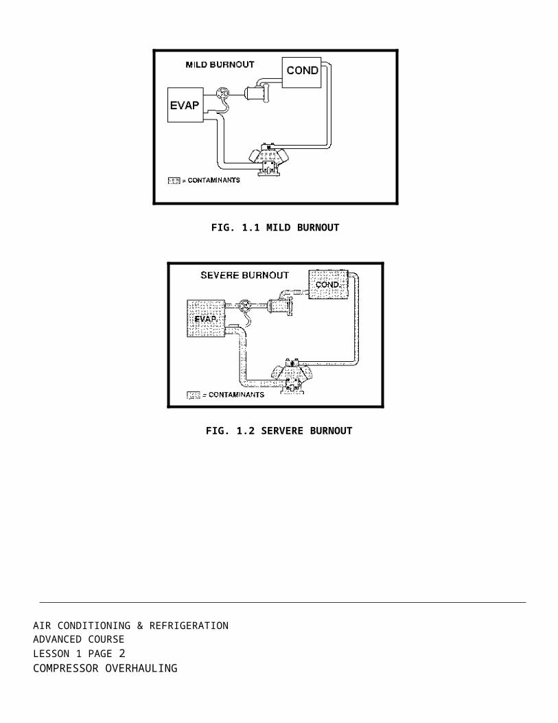
FIG. 1.2 SERVERE BURNOUT
3.0 The causes of burnout
Before an air conditioning 'system is charged with refrigerant, it must be evacuated to remove air and other non-condensable and dehydrated to remove moisture Air conditioning manufacturers go to great lengths to supply clean, dry equipment and components, Refrigeration technicians frequently nullify the work and care of the manufacturer by improper evacuation and dehydration of a new system during installation or during maintenance of an existing system. While it is necessary that evaporator coils, condensers, and piping be opened to atmosphere during installation, the service valves of the compressor should not be back-seated until after the system has been leak tested and partially evacuated This is not always possible on every system, due to the design of various, manufacturers The presence of contaminants in a system is the major factor of hermetic compressor burnouts the problem is to keep these contaminants out of the system or, once they do get in, to eliminate them before they cause serious trouble In order to do this successfully, the technician should know where they come from.A refrigeration system is, in effect, a small chemical pilot plant The unwanted products and by-products of this plant are contaminants The following are the troublemakers; moisture, metallic particles, soldering fluxes, alcohols, chemical leak detectors, hydrocarbon sludge’s, iron oxides, copper oxides, hydrofluoric acid, hydrochloric acid, acetic acid, phosgene, oxygen, and air, Some of these contaminants enter the system during manufacturing processes or field in-stallation some are formed as a result of chemical reactions, which take place within the system some develop as the result of a combination of these two factors Each of these contaminants will be examined separately to determine its affects on the refrigeration system.
AIR CONDITIONING & REFRIGERATION ADVANCED COURSE
LESSON 1 PAGE 2 COMPRESSOR OVERHAULING
3.1 Moisture and Air
Moisture is one of the chief contaminants It is present in all systems and is the most common cause of corrosion, with all its various complications and subsequent chemical reactions So all reasonable precautions should be taken to keep the moisture level in the system as low as possible Moisture in a refrigeration system often is caused by condensation from moist air which has entered the system; charging the 'system with wet refrigerant or poor grades of refrigerant oil; moisture on internal parts; or leaks in the low pressure side or water cooled condensers Moisture also can be created within the system by chemical reactions Air, with its free oxygen, may oxidize the oil and combine with the liberated hydrogen in the oil to form water Excessive moisture also may result from the breakdown of insulation in hermetic compressors. Improper evacuation can result in an excessive volume of air remaining in the system this will tend to increase head pressures and, consequently, head temperatures the increase in head temperature will tend to cause other chemical,"actions to take place within the system.
3.2 Soldering and Brazing Flux
The very function of a flux makes it harmful if it enters a refrigeration system Most of the compound, used to form either soldering or brazing fluxes are potential troublemaker,Soldering flux facilitates the wetting of a metal or molten solder One of functions of bra2ing flux is its ability to dissolve all oxides and to provide and maintain a clean metal joint surface After cleaning, the flux must protect the joint surface from air contamination and furtherOxide formations throughout the initial preheating period to a temperature at which the flux becomes chemically activeEven though fluxes may be listed as non-acid base, there is, no guarantee that they will not help to produce acid" or deteriorate on heating when mixed with various other components of a refrigeration 'system.
3.3 Iron and Copper Oxide-Iron oxide
Is formed by rusting or corrosion of any ferrous, metal parts in the 'system Water, acid, and the various metallic, Salts found in fluxes, will contribute to the formation of iron oxide or an iron base, Salt Chemical tests, have shown that refrigerant-22, at a temperature of 572°F will decompose rapidly, in fact, as much as 85% in 24 hour, in the presence of iron oxide as a fine powder Refrigerant-12 and R-134a also tend to breakdown under these 'same conditions There is definite evidence that iron oxide
ADVANCED COURSE AIR CONDITIONING & REFRIGERATION
COMPRESSOR OVERHAULING LESSON 1 PAGE 3

travels through the system, so it, should be collected at some cold location to keep it from reaching a hot spot, 'such as a compressor head, where it would act a, a catalyst in furthering a reaction For all practical purpose, the rate of decomposition may be considered to double for each 50°F increase in temperature Copper oxide promotes reaction similar to those caused by iron oxide It can be caused by air in the system, improper, soldering or brazing technique" and inefficient cleaning of component parts Copper oxide is probably most troublesome when it circulate, through the system, causing plugging at various location If flux gets into the system it may eventually dislodge any copper oxide deposits and cause this, contaminant to move through the system.
3.4 Oil and Hydrocarbon Sludge’s
Low quality oil, should not be used in a refrigeration 'system Using a good grade of refrigeration oil will decrease the amount of water that may enter the system and keep the oil from breaking down into hydrocarbon sludge Heat, water, refrigerant and acid all will help break down the oil into sludge When oxygen combines with oil it starts generating water and sludge The dark residue created when the oxygen removes the hydrogen from the carbon atom is essentially pure carbon Since it usually is impossible to oxidize oil completely, various, side reactions take place and result in the formation of acids Most refrigeration grade oils have a flock point low enough so that formation of wax is no major problem Even with a good grade of oil, however, it still is possible for the refrigerant to dewax it further and deposit this wax at some cold spot in the system. Oil which is, too highly refined will hold up exceptionally well for a, short period of time, but once it, Starts to break down it degenerate, rapidly Alcohol and Alcohol Base Solutions-The use of anhydrous, alcohol was, formerly considered a good method to prevent water freeze-up, in 'system" despite the fact that anhydrous, alcohol has a marked corrosive effect in the presence of water With the increased use of new types of insulation in hermetic windings, it has been found that alcohol has serious, embrittlement effect on these new material, It is, therefore, very important to avoid the use of alcohol or alcohol-base compound, in a refrigeration system.
3.5 Hydrochloric and Hydrofluoric Acid
These two acid, can be caused by hydrolysis, of the refrigerant This may be only a partial reaction, but once the process" has, started the conditions are, set up for a chain reaction to occur. The resulting acid, plus, the water, will activate the breakdown of the oil in the 'system The motor windings of a hermetic compressor will begin to deteriorate Heat from the compressor will cause an increase in temperature The carbon dioxide released will increase head pressure, and temperature, The excessive
AIR CONDITIONING & REFRIGERATION ADVANCED COURSE
LESSON 1 PAGE 4 COMPRESSOR OVERHAULING

heating resulting will initiate further breakdown of oil, refrigerant, and insulation These reactions, in turn, tend to, stimulate copper plating.
3.6 Acetic Acid
When any cellulose-base insulation materials in a system break down, acetic acid is formed This, is particularly true in hermetic compressor," where the refrigerant is in direct contact with the winding, The presence of this, acid accelerate, formation of various, gums and sludge.
3.7 A mild burnout
is caused by defects or damage in the winding insulation. Winding insulation is a thin layer of varnish on the windings. A spot where the varnish is too thin can cause a short, especially in the end turns. Each time the motor starts, the locked rotor inrush current flexes the winding end turns. This flexing wears off the varnish and eventually causes a short. This happens sooner if the compressor is allowed to short cycle. Scratches or nicks in the varnish can also cause a mild burnout. A motor winding can be nicked when the motor is installed in the compressor. This damage may not be serious enough to prevent the motor from passing the factory start-up test. However, when the compressor is put into operation, it may fail.Severe burnouts are caused by a combination of:1. High motor winding temperatures.2. Motor protection system failure to shut down the motor before it overheats.
FIG. 1.3 SCORCHED WINDINGS FORM A MILD BURNOUT
ADVANCED COURSE AIR CONDITIONING & REFRIGERATION
COMPRESSOR OVERHAULING LESSON 1 PAGE 5
FIG. 1.4 BURNED WINDINGDS FORM A SEVERE BURNOUT
The motor protection system includes all the safety devices in the electrical circuit (such as overcurrent protection) and switches that sense high and low pressure, oil pressure, and temperature.Wait until the unit is running again to check safety devices for proper operation. When it is back in operation check current, pressure, and temperature to ensure they do not exceed trip limits. Once it is determined why the protection system failed and the problem is corrected, the next step is to determine why the motor windings overheated. To do this, you must also wait until the system is back in operation.Overheating starts in the refrigeration or electrical systems.In the refrigeration system causes include:1. Poor installation procedures which allow moisture and air to get into the system. This causes insulation to break down.2. High head or low suction pressure, or a combination of the two. This increases the compression ratio and the current draw of the compressor.In the electrical system causes include:1. High or low voltage.2. Short cycling on controls or safety devices. This causes a buildup of heat because the heat from the previous start has not been removed.Another problem causing overheating involves both the refrigeration and electrical systems. It is called a flooded start. This happens when the compressor starts with liquid refrigerant in the crankcase. See FIG. 1.5. If there is enough liquid refrigerant in the crank case it will get into the compressor motor. There the liquid reduces resistance between the motor windings and the compressor shell or casting. If a winding leaks current through a nick or thin spot in the varnish, the refrigerant maycause the current to arc to the shell. This causes a direct short to ground. It can also cause a short between windings or a turn to-turn short. Flooding can also occur if a crankcase heater is not working or the compressor is not equipped with one.
AIR CONDITIONING & REFRIGERATION ADVANCED COURSE
LESSON 1 PAGE 6 COMPRESSOR OVERHAULING

FIG. 1.5 COMPRESSOR FLOODING
4.0 CONTAMINANTS PRODUCED BY BURNOUT
Burnout contaminants include moisture, acid, soot, varnish, hard carbon, and copper plating.
4.1 MOISTURE
Moisture in a refrigerant system causes oil sludge. This reduces lubrication, plugging oil passages and screens, as shown in FIG. 1.6
4.2 SOOT
Soot contamination is caused by soft carbon. This carbon is produced from charred insulation and oil. It is usually confined to the compressor, unless the burnout went on while the compressor continued to run. Soot is easily loosened and filtered out.
4.3 VARNISHES, HARD CARBON. AND COPPER PLATING
Varnish and hard carbon contamination are caused by excessive heat. They are the toughest of all contaminants to remove. Most varnish and carbon deposits occur in the compressor because it is the warmest spot in the system at the time of a burnout. These deposits often occur on the valve plate.Copper plating occurs on the crankshaft. It is the result of other contaminants, certain types of oil, and high temperature. The gradual buildup of copper plating on bearing surfaces reduces clearances, resulting in increased friction and wear.
ADVANCED COURSE AIR CONDITIONING & REFRIGERATION
COMPRESSOR OVERHAULING LESSON 1 PAGE 7
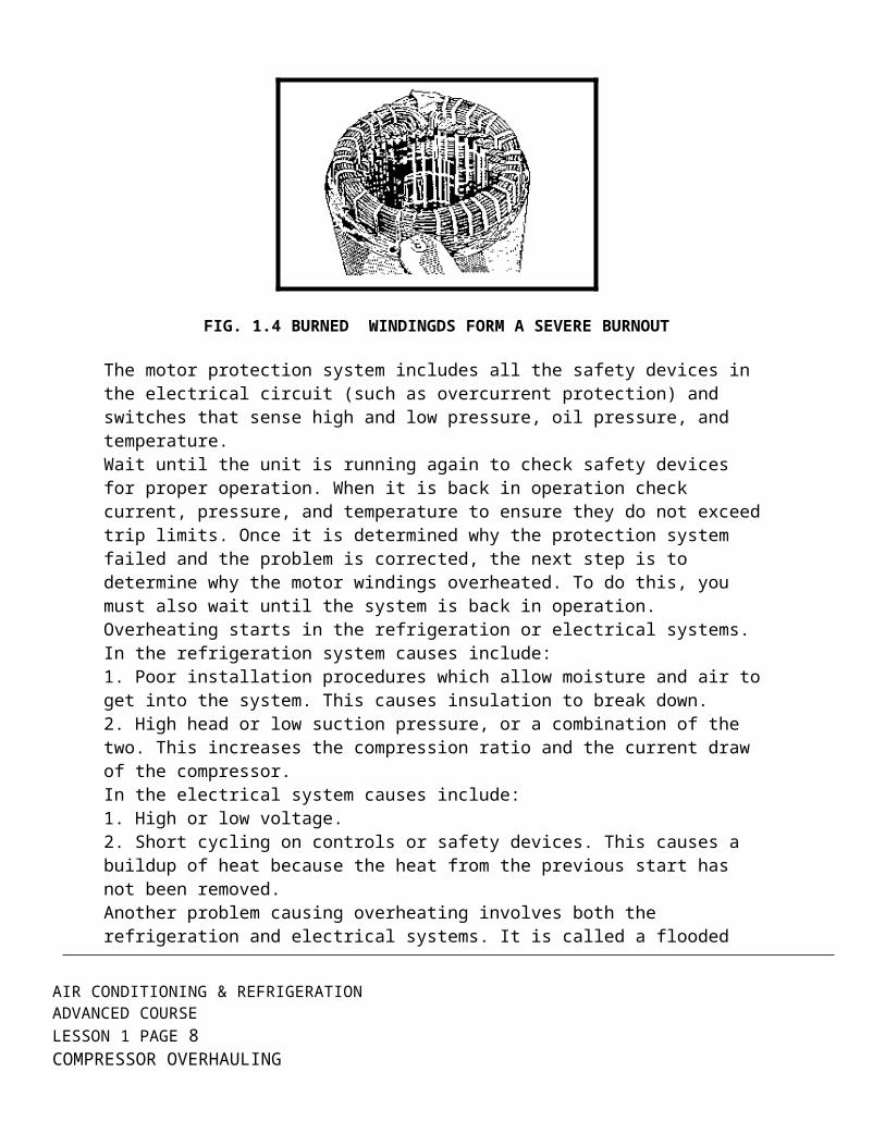
FIG. 1.6 SLUDGE-CLOGGED SCREEN
5.0 CHECKING FOR BURNOUT
There are two things to do when checking for a burnout:1. Make sure there has been a burnout.2. Determine whether the burnout is mild or severe.When checking a system always follow these safety rules:1. Make sure the electrical disconnect is off, properly tagged, and locked out as shown in FIG. 1.7.2. Wear rubber gloves and safety glasses. The refrigerant and oil mixture is acidic and can cause severe burns (FIG. 1.8).
FIG. 1.7 DISCONNECT AND LOCK OUT ELECTRIC POWER
AIR CONDITIONING & REFRIGERATION ADVANCED COURSE
LESSON 1 PAGE 8 COMPRESSOR OVERHAULING

FIG. 1.8 WEAR RUBBER GLOVES AND SAFETY GLASSES
3. Make sure the refrigerant has been removed before opening the system, as shown in FIG. 1.9.4. Cut the refrigerant piping with a tube cutter, as shown in FIG. 1.10. Do not unsweat it because the oil in the piping might ignite.
FIG. 1.9 REMOVE REFRIGERANT BEFORE OPENING SYSTEM
ADVANCED COURSE AIR CONDITIONING & REFRIGERATION
COMPRESSOR OVERHAULING LESSON 1 PAGE 9

FIG. 1.10 USE TUBE CUTTER TO CUT PIPING
To check for a burnout, measure the resistance of the compressor motor windings and the resistance to ground. Do this at the control box. Do not measure the resistance at the terminals on a compressor. See FIG. 1.11. If there has been a burnout the terminals could be loose. If you remove the wires from loose terminals the refrigerant pressure could cause a terminal to "blow out." The refrigerant and oil mixture can be discharged, causing severe burns. To determine where to disconnect the wires and place the meter probes, refer to the unit wiring diagram. Do not forget to check the condition of the wires back to the compressor. If there is a broken wire, for example, the meter will show an open circuit, causing you to think the winding is bad.On three-phase compressors the resistance of each winding should be the same.To determine the exact resistance refer to the manufacturer's specifications.
FIG. 1.11 MEASURE RESISTANCE MOTOR WINDINGS
AIR CONDITIONING & REFRIGERATION ADVANCED COURSE
LESSON 1 PAGE 10 COMPRESSOR OVERHAULING

When checking the resistance of a winding to ground on a singlephase or three-phase compressor, it must not read less than 1,000 ohms per operating volt. For example: on a 230-volt motor the resistance should not be less than 230,000 ohms (or 230 times 1, 000) . When checking a compressor with an internal line break thermostat, make sure the compressor is cold when you check the resistances. The thermostat may be open if you check a compressor when it is hot. This gives a false indication that the windings are bad.
6.0 DETERMINING SEVERITY OF A BURNOUT
Once you know the compressor motor is bad, the next step is to determine if the burnout is mild or severe. To do this on hermetic compressors, or on semi-hermetics without service valves, remove the refrigerant charge from the system. If it is a semi-hermetic compressor with service valves, valve off and bleed the refrigerant from the compressor. On a semi-hermetic compressor the simplest way to tell the type of burnout is to remove a cylinder head. If there is carbon on the valve plate and cylinder head, as shown in FIG. 1.12, contaminants have left the compressor. This means it is a severe burnout.
FIG. 1.12 CHECK CYLINDER HEAD FOR CARBON
Remove the entire refrigerant charge before cleaning the system. If there is no carbon in the head, and the motor checked out bad, it could still be either a mild or a severe burnout. To determine the type of burnout, check the acid content of the oil with an acid test kit. See FIG. 1.13. Refer to the instructions in the kit for complete details.To check out the type of burnout in a hermetic compressor, cut the discharge line and check for carbon. Lack of carbon does not mean it is a mild burnout. You must check the oil for acidity to determine the severity of burnout. However, whether it is mild or severe burnout, the refrigerant can be reused.
ADVANCED COURSE AIR CONDITIONING & REFRIGERATION
COMPRESSOR OVERHAULING LESSON 1 PAGE 11

FIG. 1.13 CHECK ACID CONTENT OF THE OIL
6.1 CLEANUP PROCEDURE FOR A MILD BURNOUT
The cleanup procedure for a mild burnout in a system with a semihermetic compressor is as follows:1. Remove the charge and compressor. With a semi-hermetic compressor you can isolate the circuit and bleed the refrigerant from the compressor, but not from the entire system.2. Add a liquid line filter-drier or, if there is one already in the system, replace it. The replacement filter-drier must be one size larger in capacity than is standard for the unit.3. Check the windings resistance to ensure they are within specifications before installing the new compressor. See FIG. 1.14.
AIR CONDITIONING & REFRIGERATION ADVANCED COURSE
LESSON 1 PAGE 12 COMPRESSOR OVERHAULING

FIG. 1.14 CHECK THE WINDINGS
4. Transfer the necessary components from the old compressor to the new one on systems with semi-hermetics. These include the crankcase heater and unloaders.5. Add an angle valve to the crankcase, as shown in FIG. 1.15. This allows you to take an oil sample for an acid test.6. Triple evacuates the system. To reduce the time of evacuation, hoses should be as short and as large in diameter as possible. The first two times the system is evacuated it should be pulled down to 5,000 microns, or 29.72 inches of mercury. Then each vacuum should be broken with the same type of refrigerant used in the system.
FIG. 1.15 ADD ANGLE VALVE TO CRANKCASE
ADVANCED COURSE AIR CONDITIONING & REFRIGERATION
COMPRESSOR OVERHAULING LESSON 1 PAGE 13

The third evacuation should be a deep vacuum of 500 microns, or 29.90 inches. A vacuum gauge, as shown in FIG. 1.16, is more accurate than a suction pressure gauge. Break the deep vacuum by recharging the system.7. Operate the system for two hours.
FIG. 1.16 TRIPLE EVACUATE THE SYSTEM
8. Take an oil sample through the angle valve and check the acid content. This is an added precaution to ensure contaminants were not pumped out of the compressor during the burnout.
6.2 CLEANUP PROCEDURE FOR A SEVERE BURNOUT
Any burnout in a hermetic system should be treated as severe. This is because the oil cannot be changed without opening the system again, which is time consuming. The following cleanup procedure is for a severe burnout.1. Remove the refrigerant charge, compressor, and liquid line filter drier (if there is one).2. Flush the piping with clean refrigerant Flush it in the direction opposite the normal refrigerant flow, as shown in FIG. 1.17. The refrigerant should be the same as the one used in the system.
AIR CONDITIONING & REFRIGERATION ADVANCED COURSE
LESSON 1 PAGE 14 COMPRESSOR OVERHAULING

FIG 1.17 FLASH THE SYSTEM OPPOSITE THE NORMAL REFRIGERATION FLOW
3. Depending on carbon buildup in the piping, refrigerant components may need to be removed and cleaned separately or replaced. These components include metering devices, accumulators, and oil separators.4. Add or replace the liquid line filter-drier. Remember, it must be one size larger in capacity than the unit. If it is a filter-drier with a replaceable core, like the one shown in FIG. 1.19, replace only the core with one the same size.5. Add a suction line filter-drier as shown in FIG. 1.18. It must be installed vertically to prevent oil entrapment. It should have Schrader valve pressure taps on the inlet and outlet.
Note: For severe burnouts both filter-driers should be the acid-core-type.
ADVANCED COURSE AIR CONDITIONING & REFRIGERATION
COMPRESSOR OVERHAULING LESSON 1 PAGE 15

FIG. 1.18 FILTER-DRIER INSTALLATION
6. Add an angle valve to the crankcase if it is a semi-hermetic compressor. Remember, this valve is used to take an oil sample for an acid test.7. Replace the compressor, triple evacuate, and recharge the system.8. Operate the unit after recharging.9. Check the pressure drop across the suction line filter drier during the operating part of the cleanup procedure. This is shown in FIG. 1.19. The pressure drop shouldnot exceed 10 pounds. If it does, replace the filter-drier. How often you check the pressure drop depends on how quickly it is changing.Always use the same gauge to measure the pressure at the inlet and outlet. If you use two different gauges they may not have the same calibration. If they are not calibrated the same, the pressure drop measurement will not be accurate.10. Change the liquid and suction line filter-driers after the unit has operated for one hour. If it is a semi-hermetic compressor change the oil.
FIG. 1.19 CHECK PRESSURE DROP ACROSS THE FILTER-DRIER
AIR CONDITIONING & REFRIGERATION ADVANCED COURSELESSON 1 PAGE 16 COMPRESSOR OVERHAULING
11. Operate the unit for two more hours. Check the complete system to determine the cause of the burnout. Correct any problems.12. Change the liquid line filter-drier after checking the unit. The suction line filter-drier must be removed from the system and replaced with tubing. If it is an hermetic compressor system the cleanup is complete.13. For semi-hermetic compressors take an oil sample and check the acid content. See FIG. 1.20. If there is no acid, the cleanup procedure is complete. If it tests acidic, change the oil.14. Operate the unit for one or two more hours and check the oil again.Note: Operating the system is the most thorough method of cleanup, when done properly. It allows the refrigerant and oil to circulate and pick up contaminants.
FIG. 1.20 TEST OIL FOR ACIDITY
7.0 CLEANUP PROCEDURE FOR MULTI - COMPRESSOR SYSTEMS
The procedure for a mild and a severe burnout in multi-compressor systems is basically the same as for a single-compressor system. Only the differences will be covered here.
7.1 HERMETIC COMPRESSORS
1. For hermetic compressors and a mild burnout, replace only the compressor that has failed.2. For a severe burnout in a system with hermetic compressors, change all the compressors in the circuit.
7.2 SEMI - HERMETIC COMPRESSORS
1. For a system with semi-hermetic compressors, replace only the failed compressor, whether it is a mild or severe burnout.2. For both mild and sever burnouts, change the oil in the good compressors in circuit.3. After operating the system, change the oil in all the compressors if the oil in the burned-out compressor is acidic.
___________________________________________________________________
ADVANCED COURSE AIR CONDITION & REFRIGERATIONCOMPRESSOR OVERHAULING LESSON 1 PAGE 17

4. For a severe burnout in a multi-circuit system, as shown in FIG. 1.21, with either hermetic or semi-hermetic compressors, install a suction line filter-drier in the common suction line of the circuit that has failed.
FIG. 1.21 TWO-CIRCUIT SYSTEM
7.3 TOOLS AND MATERIALS
Acid core driers multi-compressor unit Clamp-on ammeter (semi-hermetic) Filter-driers for suction Multimeter and discharge oil acidity test kit Gauge manifold Oxyacetylene station High vacuum pump Standard set AC hand tools Meggar Thermistor vacuum gauge.
8.0 STEPS
REPLACE A BURNOUT COMPRESSOR IN A MULTI COMPRESSOR SYSTEMNote: For details on the steps, refer to the Information Sheets.1. Disconnect power to the unit and lock it out.2. Test compressor motor winding continuity and ground. Do not remove wires from the compressor terminals.3. Determine which compressor is faulty.4. Vent the refrigerant from the faulty circuit.5. Remove a cylinder head from the faulty compressor.6. Inspect the cylinder head for traces of carbon.7. Remove an oil sample.8. Test the oil sample for acidity.9. Determine the type of burnout. (Severe burnout is when carbon is in the head and the oil is acidic. If the windings are open or shorted, but the oil is not acidic, the burnout is mild.)10. Write the type of burnout here11. Remove the burned-out compressor from the circuit. Do not heat the piping. Cut the piping with a tube cutter.Note: Follow steps 12 through 21 for a mild burnout. Follow steps 22 through 45 for a severe burnout.
AIR CONDITIONING & REFRIGERATION ADVANCED COURSELESSON 1 PAGE 18 COMPRESSOR OVERHAULING

9.0 MILD BURNOUT
12. Check the windings of the new compressor.13. Install the new compressor.14. Transfer the crankcase heater and unloaders to the new compressor, if required.15. Install an angle valve on the crankcase, if necessary.16. Change the oil in the good compressor(s) of the same unit.17. Replace the liquid line filter-drier (it must be one size larger than standard for the system).18. Evacuate the system using the triple evacuation method.19. Charge the system.20. Operate the system for two hours.21. Remove an oil sample and check it for acidity to ensure it is clean.
10.0 SEVERE BURNOUT
22. Remove the liquid line filter-drier.23. Flush the piping in the opposite direction of regular flow using the same type of refrigerant as used in the unit.24. Remove the metering device and clean it separately, if needed.25. Replace the liquid line filter-drier with one that is one size larger. Replace with the same size core (if it is a replaceable core filter-drier). Use an acid core filterdrier.26. Install a suction line filter-drier vertically with Schrader valve pressure taps on the filter-drier's inlet and outlet.27. Check the windings of the new compressor.28. Install the new compressor.29. Transfer the crankcase heater and unloaders to the new compressor, if required.30. Install an angle valve on the crankcase, if necessary.31. Change the oil in the good compressor(s) of the same circuit.32. Evacuate the system using the triple evacuation method.33. Charge the system.34. Check the cause of burnout and correct the fault(s).35. Operate the unit for two hours.36. Check the pressure drop across the suction line filter-drier. It should not exceed the manufacturer's specifications.37. Operate the unit for two more hours.38. Change the liquid line filter-drier.39. Remove the suction line filter-drier and replace with tubing.40. Remove an oil sample and check for acidity. If okay, the clean-up procedure is complete. If acidic, change the oil and liquid line filter-drier.41. Operate the unit for two more hours.42. Check oil acidity.43. Change the oil and liquid line filter-drier. Repeat steps 41 and 42 until the oil no longer tests acidic.
___________________________________________________________________
ADVANCED COURSE AIR CONDITION & REFRIGERATIONCOMPRESSOR OVERHAULING LESSON 1 PAGE 19

44. When the oil is clean and no longer acidic, replace the liquid line filter-drier with a regular one, instead of one with an acid core.45. Clean up work area.
AIR CONDITIONING & REFRIGERATION ADVANCED COURSELESSON 1 PAGE 20 COMPRESSOR OVERHAULING


![Con Air 1997 DvDrip[Eng]-Greenbud1969](https://static.fdocuments.net/doc/165x107/55cf9671550346d0338b7d77/con-air-1997-dvdripeng-greenbud1969.jpg)